Battery-Electrical & Hybrid-Electrical Vehicles MAGNETI MARELLI ...

HAL Id: hal-01722852https://hal.archives-ouvertes.fr/hal-01722852
Submitted on 5 Mar 2018
HAL is a multi-disciplinary open accessarchive for the deposit and dissemination of sci-entific research documents, whether they are pub-lished or not. The documents may come fromteaching and research institutions in France orabroad, or from public or private research centers.
L’archive ouverte pluridisciplinaire HAL, estdestinée au dépôt et à la diffusion de documentsscientifiques de niveau recherche, publiés ou non,émanant des établissements d’enseignement et derecherche français ou étrangers, des laboratoirespublics ou privés.
Hybrid power generation system for aircraft electricalemergency network
Xavier Roboam, Olivier Langlois, Hubert Piquet, Benoît Morin, ChristopheTurpin
To cite this version:Xavier Roboam, Olivier Langlois, Hubert Piquet, Benoît Morin, Christophe Turpin. Hybrid powergeneration system for aircraft electrical emergency network. IET Electrical Systems in Transportation,IEEE, 2011, vol. 1 (n° 4), pp. 148-155. �10.1049/iet-est.2010.0045�. �hal-01722852�

Open Archive TOULOUSE Archive Ouverte (OATAO) OATAO is an open access repository that collects the work of Toulouse researchers andmakes it freely available over the web where possible.
This is an author-deposited version published in : http://oatao.univ-toulouse.fr/Eprints ID : 19619
To link to this article : DOI:10.1049/iet-est.2010.0045 URL : http://dx.doi.org/10.1049/iet-est.2010.0045
To cite this version : Roboam, Xavier and Langlois, Olivier and
Piquet, Hubert and Morin, Benoît and Turpin, ChristopheHybrid power generation system for aircraft electrical emergencynetwork. (2011) IET Electrical Systems in Transportation, vol. 1 (n°4). pp. 148-155. ISSN 2042-9738
Any correspondence concerning this service should be sent to the repository
administrator: [email protected]
Hybrid power generation system for aircraft electricalemergency networkX. Roboam1 O. Langlois2 H. Piquet1 B. Morin1 C. Turpin1
1LAPLACE, Universite de Toulouse, UMR CNRS-INPT-UPS, site ENSEEIHT, 2 rue Camichel, BP7122, 31071 Toulouse,Cedex 7, France2Airbus operation SAS, 316 route de Bayonne, 31060 Toulouse, Cedex 9, FranceE-mail: [email protected]
Abstract: A whole structure and two management strategies are proposed here for hybridisation of a Ram air turbine (RAT) bymeans of supercapacitors. Such hybrid structure is dedicated to an aircraft emergency network. The structure consists in coupling,through a 270 V DC bus, a controlled source (RAT) with a storage device interfaced through a bidirectional DC–DC converter.Both the energy-management strategies are described and analysed: the first one is to assign the ‘high-frequency harmonics’ of theload power to the storage which is current controlled, whereas the RAT controls the bus voltage and then only feeds the averagepower, losses and low-frequency harmonics of the load. The second one proposes an energy optimised operation of the system:the RAT, being current controlled, is able to maximise the supplied power (maximum power point tracking), as for classical windturbines. For such a strategy, the bus voltage is regulated from the storage device. The RAT sizing and its mass can then bestrongly reduced by means of this hybrid structure controlled with optimised management strategies. Experiments on a labtest-bench confirm analyses presented.
decrease the sizing of the main source (weight, volume) orincrease life duration.
In this paper, the authors mainly focus on energy-management strategies for a RAT - SC hybrid emergencynetwork for aircraft application. After synthesising therequirements and context of this study, two managementstrategies are proposed and analysed by simulations. Thisanalysis shows this controlled system’s capability to bereduced in terms of size and mass, compared with theactual uncontrolled system. The analysis is confirmed bythe experiments based on a reduced power test-bench.
2 Emergency network description andrequirements
A full electrical emergency network is considered here. In thecase of an electrical power fault possibly due to a total enginefailure, essential loads have to be powered. Three classes ofessential loads are fed: there are avionic loads on a lowvoltage 28 V DC bus, and some essential loads are fed on a‘high voltage bus’ (here 115 V AC), for example, foressential lightning. But the main part of the power needs isdue to flight control actuators. The first two groups of loadscan be considered as nearly constant as the third one isstrongly intermittent (see Fig. 1). An example of anemergency subsystem is highlighted in Fig. 1. During thisemergency operation, energy generation is often ensured bya high speed wind turbine (i.e. the RAT) that unfolds incase of engine failure. This turbine is currently sized to
1 Introduction
The ‘more electric aircraft’ involves a lot of changes to electrical networks and embedded powers [1]: a large EU project has recently demonstrated the advantages in terms of flexibility and energy optimisation [2]. Several subsystems become ‘more electrical’ such as for flight control [3, 4] and pumps. Other functions will also be electrically powered in the future, such as braking, air conditioning [5], anti-ice systems or starters/generators [1, 6]. This paper focuses especially on the emergency sub-network: a full electrical power is used in modern aircrafts for emergency situations as on the A380 [7, 8]. Aerospace requirements for such an application lead to fulfilling the emergency flight mission with a minimised embedded weight. During this operation, energy generation is often ensured by a high speed wind turbine (Ram air turbine –RAT) that unfolds in case of engine failure. This turbine is currently sized to provide the maximum power that the aircraft may require during its emergency mission. In such a case, the main power demand is due to flight control actuators and is strongly intermittent.
The main issue of this paper is then to propose a hybrid structure of the emergency network coupling the RAT with a storage device: this issue has been studied in the PhD thesis of Langlois [8]. Many papers deal with hybrid systems in aircrafts [9] or for other applications [10–13]. Several source technologies (i.e. fuel cells, turbines, etc.) can be coupled with storage technologies (batteries or supercapacitors (SCs)) to increase system performance,

provide the maximum power that the aircraft may requireduring its emergency mission. In such a case, the mainpower demand is due to flight control actuators: the motionof flight control surfaces is carried out by electro-hydraulicactuators or electro-mechanical actuators [3, 4], which needhigh power during short time intervals. This results in ahighly intermittent profile where the peak power is abouttwice as high as the average power [8]. This power cycle isgiven for the most compelling case, when the aircraft isapproaching the landing phase at low altitude: RAT poweris at minimum due to low aircraft speed while many flightcontrol actuators are operated simultaneously due toturbulent conditions. Instead of the ‘AC ESS BUS’equivalent to an AC bus which appears on Fig. 2, a highvoltage 270 V DC bus is considered. This study is focusedon the hybridisation of this DC bus. Concerning voltagesand currents associated with the AC loads, equivalent DCquantities are introduced and used for analyses.
3 Energy-management strategies formulti-sources device
Many studies dedicated to embedded systems havedemonstrated that a significant reduction in weight andvolume of the whole system can be obtained by hybridisingthe main source with storage devices. Several storagecomponent technologies may be used for that purpose. The
energy against power Ragone plot [14] Q1is usually used toselect a technology with respect to the missionrequirements: batteries are preferred if energy needs areimportant, while SC constitute the best choice if the powerneed is of prime importance with short durations of powerpeaks. Many papers have focused on power-sharingoptimisation by means of batteries or SC [11–13]. In ourcase study, with regard to the considered load profile (seeFig. 1), the best weight–power ratio and safe operation forstorage appliances are given for SC. A complete study onthat topic has been made in [8]. The general issue ofhybridisation consists in providing the average power andlosses from the main power supply (i.e. the RAT), whiletransients are covered by the storage (i.e. SC): thisoperation is called ‘power-sharing’ [13].
Considering that sources and loads of the hybrid system arecoupled through a 270 V DC bus, as illustrated in Fig. 5, Q2wehave chosen a serial connection of SC (BPAK0058E15: 15 V,58 F Maxwell modules) [15] to obtain a maximum voltagevalue of 250 V. Classically, SC are discharged by 50%, thatis a minimum voltage of 125 V, thus providing 75% of themaximum stored energy. A power reversible DC–DCchopper is then chosen to connect the SC with the 270 VDC bus.
The process for storage sizing based on the Ragone plotanalysis is illustrated in Fig. 3. A correct storage sizingallows to fulfil the power–energy needs when the ‘mission’cycle is kept inside the cycle involved by the SC battery,taking into account voltage (‘SC V bounds’) and current(‘SC I bounds’) limits.
System simulations have been performed for the completestructure using the SABER software. As mentioned in Section2, the RAT–generator–rectifier set, as seen from the ‘point ofregulation’ (on which the loads will be connected) ismodelled through a DC equivalent model detailed in [8]. Theequivalent model structure is illustrated for the generator–rectifier in Figs. 4 and 5: EDC is the rectified RAT voltage; ittakes into account the voltage drop due to diode overlaps.
A bond graph approach has been considered formodelling, as proposed in [3]. The load power presented
Fig. 1 Typical sizing flight cycle for electrical emergency
Fig. 2 More electrical aircraft bi-motor architecture (emergency sub-network is highlighted)

in Fig. 1 merges currents due to constant loads (for avionicand constant essential loads) and due to intermittent loads,for instance, the flight control actuators achieving themission cycle.
Two different strategies are described in the nextsubsections to interface the RAT and the storage device.‘Sizing models’ for the RAT turbine and its generator aswell as for the DC-DC chopper have been developed in[8]: these models are used to resize these devicesaccording to the selected power ratings. Volume andweight are two of the outputs of the sizing models. Thetask is easy for the storage devices, which are naturallymodular: the characteristics of the whole device arederived from both mass and volume of one of theassociated SC element.
3.1 Conventional strategy
The RAT is the main energy source [8]: it is composed oftwo-blade wind turbine. The pitch angle of the blades q isadjusted by an autonomous passive mechanical system forblades stalling. The turbine is coupled to a synchronousgenerator (SG) through a speed multiplier. For a 270 V DCsub-network, a diode bridge is connected between thegenerator and the DC bus capacitance to rectify the voltage.The voltage delivered by the RAT is controlled by meansof the excitation voltage Vex, which adjusts the field current.This latter defines the no-load voltage of the DC busproportionally. So, a first ‘classical’ idea should be tocontrol the current of the storage device to provide thehigh-frequency harmonics of the load, as illustrated inFig. 5: a high-pass filtering is set on the measured loadcurrent Iloads to provide the value of the high-frequenciescurrent (Iloads
HF ) that will be requested from the storagedevice (Istor
ref ¼ IloadsHF ). Thus, the RAT has to provide only
the low-frequency harmonics, especially the average powerand system losses. Remembering that 50% of the loadpower is intermittent, one can easily conclude that such astrategy will lead to a significant RAT sizing reduction.
The current reference that has to be provided or accepted bythe storage device Istor is in fact controlled on the low voltageside of the bidirectional DC–DC chopper (ISC): the SCreference current Iideal SC
ref is obtained applying a gain whichresults due to power balance. Consequently, the SC currentcontroller computes the duty cycle (a) which drives theDC-DC chopper. To complete the description of this first
Fig. 3 Three different SC sizing from Ragone plot analysis
Fig. 4 Electrical scheme and its equivalent DC circuit
a Whole system structureb DC equivalent generator

management strategy, the state of charge (SOC) of the SCbattery is ensured, thanks to a slow dynamic control loopthat regulates the SC voltage (VSC
ref ) and compensates thelosses of the DC–DC chopper. The reference forthe corresponding additional current (ISC
SOC) is then added tothe Iideal SC
ref reference of the storage control loop.On the one hand, the control of the SC voltage needs to
ensure a convenient SOC in case of high power demand.On the other hand, this control loop has to be slow enoughto allow SC voltage variations in order to allow the SC toprovide power over the desired frequency range. This loopis also useful to compensate losses in the SC device (SCand DC–DC chopper) over a long operation time.
It should be noted that every controller (‘Reg X’) of Fig. 5correspond with a proportional–integral (PI) structure.
Fig. 6 illustrates the operation of the hybrid network withthis ‘classical’ strategy. As planned in the managementstrategy, the RAT power (PRAT) is significantly reducedwith respect to the full power of loads (Ploads). Only the SCdevice is charged and discharged with the high-frequencycomponents: in this simulation case, the filtering frequencyhas been set to 10 mHz, leading to a correct power-sharingclose to 50%. We have also verified that the voltage of theSC, and then its SOC, is correctly maintained along thewhole cycle.
However, a sharp analysis of the controlled system showsthat the RAT does not provide its maximum power withrespect to the flight conditions (relative speed of the aircraftagainst wind): the operation of the wind turbine is notcompletely optimised. For that purpose, another strategy ispresented in the next subsection.
3.2 ‘Dual-optimised’ strategy with maximumpower point tracking (MPPT)
This new strategy proposes to exchange the nature of bothassociated sources. Indeed, the architecture is the same asthe previous one, but the sources control is dual: the mainsource, the RAT, is now current controlled, whereas the SCdevice together with its bidirectional chopper regulates thebus voltage.
This inversion has two advantages:
† It increases the dynamic of the bus voltage loop, thusenhancing the voltage waveform quality, thanks to the highdynamics of the storage subsystem with regard to the RATsubsystem.† It benefits from a new degree of freedom in the RATsubsystem: the excitation field of the generator controls thepower delivered by the RAT.
This last issue is of prime importance, as the RAT canprovide a maximum power along the emergency cycle. Asfor classical wind turbine systems, an MPPT strategy can beset following the load power and the SC SOC [16].However, an issue is to be able to leave the MPPT modeand to ‘decrease’ the RAT power operation when neitherthe load nor the SOC of the storage device requiremaximising the power:
† A ‘normal’ mode is simply defined: the RAT provides thefull power required by the load. During this mode, the SOC ofthe SC device remains nearly constant.† The ‘MPPT’ mode is only activated if the load powerdemand becomes higher than the RAT maximum power, orif the SC voltage is below a voltage bound (VSC
min).Otherwise in this mode, the storage device naturallyprovides the rest of the demanded power by regulating thebus voltage. Note that MPPT operation is maintained untilthe SC voltage is re-established (VSC
max).
The synoptic of Fig. 7 describes the control strategy. Thesame functions as for Fig. 5 are displayed, but here the SCvoltage is now controlled inside the MPPT block. The storagesubsystem is only in charge of bus regulation. Furthermore,the excitation voltage (Vexcitation) of the generator is now givenby the output of the RAT current controller.
The operation of the RAT against speed, especially atmaximum power (MPPT mode), is slightly complex due tovariations in the blade’s tip angle. To summarise this issue(see Fig. 8b), note that the tip angle q is directly linkedwith the rotation speed of the wind turbine VT. When
Fig. 5 ‘Classical’ structure for RAT – SC hybridisation
Fig. 6 Behaviour of the classical management strategy

mechanical constraints are smooth (low aircraft speed and/orlow-speed operation), a constant tip angle (q ¼ qb) is kept atlow speeds (VT , VTb). Oppositely, when the rotation speedincreases (higher constraints: VT . VTb), the tip angle q
becomes variable to stall the blades and to limit mechanicalconstraints: q . qb when VT . VTb.
The MPPT mode is ensured, as illustrated in Fig. 7b, byfollowing the dashed characteristic: note that power
Fig. 7 ‘Dual’ optimised management strategy with MPPT
Fig. 8 Behaviour of the ‘dual’ optimised management strategy with MPPT
a Chronogram of powers, mode, turbine rotation speed and SC voltageb Power–speed characteristics against turbine rotation speed
I
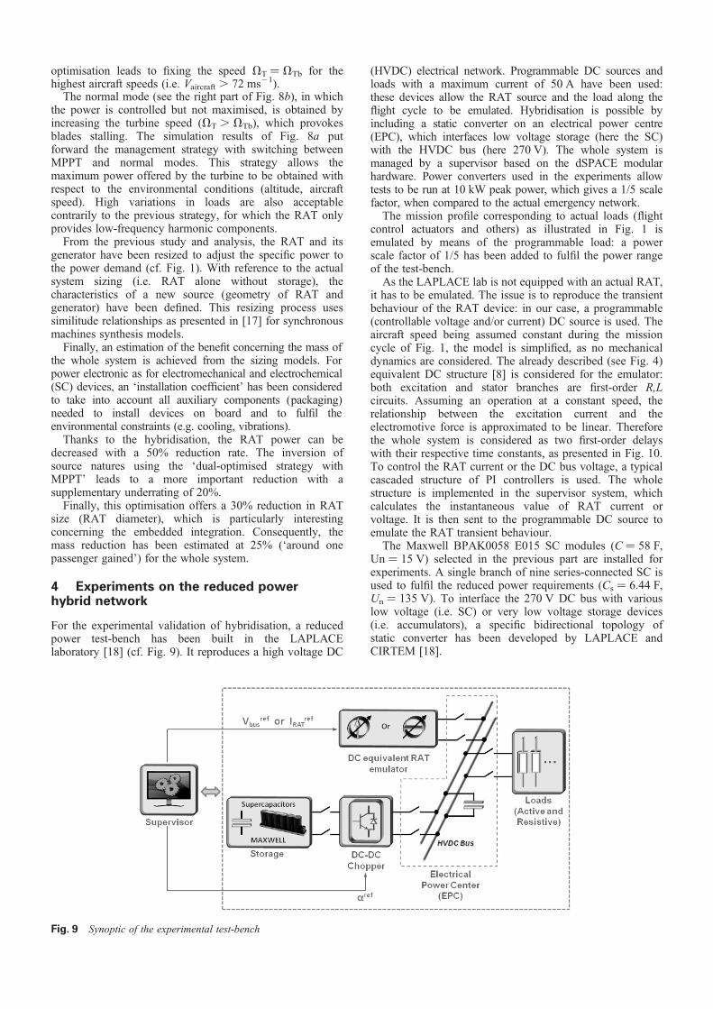
(HVDC) electrical network. Programmable DC sources andloads with a maximum current of 50 A have been used:these devices allow the RAT source and the load along theflight cycle to be emulated. Hybridisation is possible byincluding a static converter on an electrical power centre(EPC), which interfaces low voltage storage (here the SC)with the HVDC bus (here 270 V). The whole system ismanaged by a supervisor based on the dSPACE modularhardware. Power converters used in the experiments allowtests to be run at 10 kW peak power, which gives a 1/5 scalefactor, when compared to the actual emergency network.
The mission profile corresponding to actual loads (flightcontrol actuators and others) as illustrated in Fig. 1 isemulated by means of the programmable load: a powerscale factor of 1/5 has been added to fulfil the power rangeof the test-bench.
As the LAPLACE lab is not equipped with an actual RAT,it has to be emulated. The issue is to reproduce the transientbehaviour of the RAT device: in our case, a programmable(controllable voltage and/or current) DC source is used. Theaircraft speed being assumed constant during the missioncycle of Fig. 1, the model is simplified, as no mechanicaldynamics are considered. The already described (see Fig. 4)equivalent DC structure [8] is considered for the emulator:both excitation and stator branches are first-order R,Lcircuits. Assuming an operation at a constant speed, therelationship between the excitation current and theelectromotive force is approximated to be linear. Thereforethe whole system is considered as two first-order delayswith their respective time constants, as presented in Fig. 10.To control the RAT current or the DC bus voltage, a typicalcascaded structure of PI controllers is used. The wholestructure is implemented in the supervisor system, whichcalculates the instantaneous value of RAT current orvoltage. It is then sent to the programmable DC source toemulate the RAT transient behaviour.
The Maxwell BPAK0058 E015 SC modules (C ¼ 58 F,Un ¼ 15 V) selected in the previous part are installed forexperiments. A single branch of nine series-connected SC isused to fulfil the reduced power requirements (Cs ¼ 6.44 F,Un ¼ 135 V). To interface the 270 V DC bus with variouslow voltage (i.e. SC) or very low voltage storage devices(i.e. accumulators), a specific bidirectional topology ofstatic converter has been developed by LAPLACE andCIRTEM [18].
Fig. 9 Synoptic of the experimental test-bench
optimisation leads to fixing the speed VT ¼ VTb for the highest aircraft speeds (i.e. Vaircraft . 72 ms21).
The normal mode (see the right part of Fig. 8b), in which the power is controlled but not maximised, is obtained by increasing the turbine speed (VT . VTb), which provokes blades stalling. The simulation results of Fig. 8a put forward the management strategy with switching between MPPT and normal modes. This strategy allows the maximum power offered by the turbine to be obtained with respect to the environmental conditions (altitude, aircraft speed). High variations in loads are also acceptable contrarily to the previous strategy, for which the RAT only provides low-frequency harmonic components.
From the previous study and analysis, the RAT and its generator have been resized to adjust the specific power to the power demand (cf. Fig. 1). With reference to the actual system sizing (i.e. RAT alone without storage), the characteristics of a new source (geometry of RAT and generator) have been defined. This resizing process uses similitude relationships as presented in [17] for synchronous machines synthesis models.
Finally, an estimation of the benefit concerning the mass of the whole system is achieved from the sizing models. For power electronic as for electromechanical and electrochemical (SC) devices, an ‘installation coefficient’ has been considered to take into account all auxiliary components (packaging) needed to install devices on board and to fulfil the environmental constraints (e.g. cooling, vibrations).
Thanks to the hybridisation, the RAT power can be decreased with a 50% reduction rate. The inversion of source natures using the ‘dual-optimised strategy with MPPT’ leads to a more important reduction with a supplementary underrating of 20%.
Finally, this optimisation offers a 30% reduction in RAT size (RAT diameter), which is particularly interesting concerning the embedded integration. Consequently, the mass reduction has been estimated at 25% (‘around one passenger gained’) for the whole system.
4 Experiments on the reduced power hybrid network
For the experimental validation of hybridisation, a reduced power test-bench has been built in the LAPLACE laboratory [18] (cf. Fig. 9). It reproduces a high voltage DC

In the figures below, experimental results obtained on thelab test-bench are presented, with the system beingconfigured as follows:
† nine super capacitors are connected in series;† HVDC bus voltage is controlled to 270 V;† a DC programmable source emulates RAT dynamics;† the cut-off frequency of power-sharing filter is set at10 mHz;† the load profile has 5 kW average power and 10 kW peakpower (1/5 ratio against actual profile).
The captured waveforms present 270 V DC bus andcapacitor bank voltages with RAT, storage and loadcurrents for the two strategies.
Figs. 11 and 12 display results concerning, respectively, the‘classical’ and the ‘dual’ strategies. The whole mission cycleand a zoom on the peak power demand are presented. The
filtering effect on the RAT current can be observed in bothcases and this proves the capability of the hybridisation toreduce the RAT sizing. Indeed, as the maximum loadcurrent is 25 A, the one provided by the RAT is only 15 A(i.e. �60%). Based on these experiments for which theMPPT operation of RAT has not been considered (as theactual RAT is unavailable), the reduction effect appears tobe the same for both strategies, even if the ‘dual’ one hasbeen shown in the previous part to be optimised in terms ofsize reduction (weight reduction) capability.
The zoom presented in Figs. 11 and 12 shows that alldynamics of sources are conveniently controlled, especiallythe SC SOC, which is kept around its nominal operation allalong the mission profile.
5 Conclusion
In this paper, two hybridisation strategies have been studiedand analysed by simulation and then tested on anexperimental test-bench. The hybrid structure connectstogether a RAT device with a storage subsystem equipped
Fig. 10 Dynamic model of RAT used for emulation
Fig. 12 ‘Dual’ hybridisation with RAT emulation (RAT in currentmode, storage in voltage mode)
a Hybridisation on 90 s (one full load profile)b Zoom on peak power
Fig. 11 ‘Classical’ hybridisation with RAT emulation (RAT involtage mode, storage in current mode)
a Hybridisation on 90 s (one full load profile)b Zoom on peak power

more electric aircraft’, IEEE Aerosp. Electron. Syst. Mag., 2007, 22, (3),pp. 3–9
2 MOET (More Opened Electrical Technologies): ‘Final technical report’,EU FP6 project, http://www.eurtd.com/moet/, December 2009
3 Langlois, O., Roboam, X., Mare, J-C., Piquet, H., Gandanegara, G.:‘Bond graph modelling of an electro-hydrostatic actuator foraeronautic applications’ (IMACS, Paris, France, 2005)
4 Van Den Bossche, D.: ‘More electric control surface actuation – astandard for the next generation of transport aircraft’. Tenth EuropeanPower Electronics and Applications Conf., Toulouse, France, 2003
5 Ensign, Th.R.: ‘Performance and weight impact of electricenvironmental control system and more electric engine on citationCJ2’. 45th AIAA (Aerospace Sciences Meeting and Exhibit), Reno,Nevada, January 2007, pp. 8–11
6 Raimondi, G.M., Sawata, T., Holme, M., et al.: ‘Aircraft embeddedgeneration systems’. IET PEMD Conf., Dublin, No. 487, 2002,pp. 217–222
7 Koerner, M.: ‘Recent developments in aircraft emergency power’. IEEEConf., IECEC, Las Vegas, NV, 2000, vol. 1, pp. 12–19
8 Langlois, O.: ‘Conception d’un reseau de secours electrique pourl’aeronautique’. PhD thesis of Universite de Toulouse, INPT/LAPLACE, France, June 2006, http://ethesis.inp-toulouse.fr/archive/00000243/
9 Bataller-planes, E., Lapenza-Rey, N., Mosquera, J., et al.: ‘Powerbalance of a hybrid power source in a power plant for a smallpropulsion aircraft’, IEEE Trans. Power Electron., 2009, 24, (11–12),pp. 2856–2866
10 ‘Design and implementation of a DSP-based fuel Q3cell-battery hybridpower source’. IET PEMD Conf., 2004
11 Ayad, M.Y., Becherif, M., Djerdir, A., Miraoui, A.: ‘Sliding modecontrol for energy management of DC hybrid power sources usingfuel cell, batteries and supercapacitors’. IEEE Conf., ICCEP, Capri,2007
12 Awerbuch, J.J., Sullivan, C.R.: ‘Control of ultracapacitor-battery hybridpower source for vehicular applications’. IEEE Conf., Energy, Atlanta,GA, 2008
13 Gao, L., Dougal, R.A., Liu, S.: ‘Active power sharing in hybrid battery-capacitor power sources’. IEEE Conf., APEC, 2003
14 Christen, T., Carlen, M.W.: ‘Theory of Ragone plots’, J. Power Sources,2000, 91, (2000), pp. 210–216
15 Maxwell technologies and products: http://www.maxwell.com/ultracapacitors/products/
16 Siegfried, H.: ‘Grid integration of wind energy conversion systems’(Wiley, 1998)
17 Fefermann, Y., Randi, S.A., Astier, S., Roboam, X.: ‘Synthesis modelsof PM brushless motors for the design of complex and heterogeneoussystem’. EPE’01, Graz, Austria, September 2001
18 Rafal, K., Morin, B., Roboam, X., Bru, E., Turpin, C., Piquet, H.:‘Experimental validation of hybrid emergency electrical network foraircraft application’. IEEE VPPC Conf., Lille, France, September 2010
with an interfacing converter connected to a SC bank. The DC–DC converter structure allows an HVDC (270 V) bus to be interfaced with variable storage voltages (SC) with convenient energy efficiency. The obtained experimental results confirm the conclusions of the theoretical study: such an hybridised structure associating the RAT with SCs allows to significantly reduce the system weight: the mass reduction has been estimated as 25%. The dynamic behaviours of both strategies (‘classical’ and ‘dual’) are nearly equivalent, even if the dual one allows a faster bus regulation and maintains the system’s stability during transient operation. The experiments have especially confirmed that the proposed control and management realise efficient RAT current filtering and SCs SOC control.
6 Acknowledgment
Experiments presented in this paper have been conducted, thanks to the support of the French national project Innovative Solutions for Systems (ISS) Power supported by Direction Generale de l’Armement (DGA).
7 References
1 Rosero, J.A., Ortega, J.A., Aldabas, E., Romeral, L.: ‘Moving towards a