
Hybrid Electric Vehicle Charging by Solar Panel Using of ...
9
International Journal of Trend in Scientific Research and Development (IJTSRD) Volume 5 Issue 5, July-August 2021 Available Online: www.ijtsrd.com e-ISSN: 2456 – 6470 @ IJTSRD | Unique Paper ID – IJTSRD45037 | Volume – 5 | Issue – 5 | Jul-Aug 2021 Page 1151 Hybrid Electric Vehicle Charging by Solar Panel using of Supercapacitors Satya Veer Singh 1 , Poonam Kumari 2 1 M Tech, Instrumentation, UCIM, Panjab University, Chandigarh, India 2 Assistant Professor, UCIM, Panjab University, Chandigarh, India ABSTRACT In recent years, the demand for electric (EV) has increased drastically because of the rising pollution from emissions into the atmosphere in recent years. EV’s have simpler architecture, lower noise levels, better stability, and, most significantly, they safeguard the environment. Rapidly increasing population, energy consumption, and the need to reduce emissions through the conventional vehicle have motivated researchers to study the electric hybrid vehicles (EHVs). In normal scenario in INDIA in electric vehicles like E-cabs and E-cars conventional battery is used and the real drawback of conventional batteries is that it drained out fast when used with full capacity and rechargeable is time significantly high usually 7 to 8 hours. A large number of methods have already been already proposed by various researchers that can solve the problem, however, these systems were not efficient enough for draining out the charging in EV. In order to overcome the limitation rapid discharge and slow recharge supercapacitors can be very significant solution of this problems. Using of solar panel is precure our environment which can be most important thing in this developing and growing world the use of solar in vehicle and using electric cars can be safeguard of our society and we can be free from using petroleum fuels which are limited and world can be made safer for our upcoming generations. supercapacitor used as additional energy storage for hybrid wind and photovoltaic system. It charges energy when it is windy or sunny and discharges when there is no power generated from photovoltaic or wind due to the sudden passing clouds disturbance or very low wind speed. Hence, it is necessary to understand the characteristics of the supercapacitor and determine these different electric models. KEYWORDS: Electric vehicles, solar energy, Supercapacitors, Environment, Petroleum fuels, Energy Storage for hybrid wind and photovoltaic system How to cite this paper: Satya Veer Singh | Poonam Kumari "Hybrid Electric Vehicle Charging by Solar Panel using of Supercapacitors" Published in International Journal of Trend in Scientific Research and Development (ijtsrd), ISSN: 2456- 6470, Volume-5 | Issue-5, August 2021, pp.1151-1159, URL: www.ijtsrd.com/papers/ijtsrd45037.pdf Copyright © 2021 by author (s) and International Journal of Trend in Scientific Research and Development Journal. This is an Open Access article distributed under the terms of the Creative Commons Attribution License (CC BY 4.0) (http://creativecommons.org/licenses/by/4.0) 1. INTRODUCTION Electrical vehicle (EV) based on electric propulsion system. No internal combustion engine is used. All the power is based on electric power as the energy source. The main advantage is the high efficiency in power conversion through its proposition system of electric motor. Recently there has been massive research and development work reported in both academic and industry. Commercial vehicles are also available. Many countries have provided incentive to users through lower tax or tax exemption, free parking and free charging facilities. On the other hand, the hybrid electric vehicle (HEV) is an alternative. It has been used extensive in the last few years. Nearly all the car manufacturers have at least one model in hybrid electric vehicle. The questions come to us: Which vehicle will dominate the market and which one is suitable for future? Electric vehicles (EVs) are receiving considerable attention as effective solutions for energy and environmental challenges. The hybrid energy storage system (HESS), which includes batteries and supercapacitors (SCs), has been widely studied for use in EVs and plug-in hybrid electric vehicles. The core reason of adopting HESS is to prolong the life IJTSRD45037
Transcript of Hybrid Electric Vehicle Charging by Solar Panel Using of ...
International Journal of Trend in Scientific Research and Development (IJTSRD)
Volume 5 Issue 5, July-August 2021 Available Online: www.ijtsrd.com e-ISSN: 2456 – 6470
@ IJTSRD | Unique Paper ID – IJTSRD45037 | Volume – 5 | Issue – 5 | Jul-Aug 2021 Page 1151
Hybrid Electric Vehicle Charging by
Solar Panel using of Supercapacitors
Satya Veer Singh1, Poonam Kumari
2
1M Tech, Instrumentation, UCIM, Panjab University, Chandigarh, India 2Assistant Professor, UCIM, Panjab University, Chandigarh, India
ABSTRACT
In recent years, the demand for electric (EV) has increased drastically because of the rising pollution from emissions into the atmosphere in recent years. EV’s have simpler architecture, lower noise levels, better stability, and, most significantly, they safeguard the environment. Rapidly increasing population, energy consumption, and the need to reduce emissions through the conventional vehicle have motivated researchers to study the electric hybrid vehicles (EHVs). In normal scenario in INDIA in electric vehicles like E-cabs and E-cars conventional battery is used and the real drawback of conventional batteries is that it drained out fast when used with full capacity and rechargeable is time significantly high usually 7 to 8 hours. A large number of methods have already been already proposed by various researchers that can solve the problem, however, these systems were not efficient enough for draining out the charging in EV. In order to overcome the limitation rapid discharge and slow recharge supercapacitors can be very significant solution of this problems. Using of solar panel is precure our environment which can be most important thing in this developing and growing world the use of solar in vehicle and using electric cars can be safeguard of our society and we can be free from using petroleum fuels which are limited and world can be made safer for our upcoming generations. supercapacitor used as additional energy storage for hybrid wind and photovoltaic system. It charges energy when it is windy or sunny and discharges when there is no power generated from photovoltaic or wind due to the sudden passing clouds disturbance or very low wind speed. Hence, it is necessary to understand the characteristics of the supercapacitor and determine these different electric models.
KEYWORDS: Electric vehicles, solar energy, Supercapacitors,
Environment, Petroleum fuels, Energy Storage for hybrid wind and
photovoltaic system
How to cite this paper: Satya Veer Singh | Poonam Kumari "Hybrid Electric Vehicle Charging by Solar Panel using of Supercapacitors" Published in International Journal of Trend in Scientific Research and Development (ijtsrd), ISSN: 2456-6470, Volume-5 | Issue-5, August 2021, pp.1151-1159, URL: www.ijtsrd.com/papers/ijtsrd45037.pdf Copyright © 2021 by author (s) and International Journal of Trend in Scientific Research and Development Journal. This is an Open Access article distributed under the terms of the Creative Commons Attribution License (CC BY 4.0) (http://creativecommons.org/licenses/by/4.0)
1. INTRODUCTION
Electrical vehicle (EV) based on electric propulsion system. No internal combustion engine is used. All the power is based on electric power as the energy source. The main advantage is the high efficiency in power conversion through its proposition system of electric motor. Recently there has been massive research and development work reported in both academic and industry. Commercial vehicles are also available. Many countries have provided incentive to users through lower tax or tax exemption, free parking and free charging facilities. On the other hand, the hybrid electric vehicle (HEV) is an
alternative. It has been used extensive in the last few years. Nearly all the car manufacturers have at least one model in hybrid electric vehicle. The questions come to us: Which vehicle will dominate the market and which one is suitable for future?
Electric vehicles (EVs) are receiving considerable attention as effective solutions for energy and environmental challenges. The hybrid energy storage system (HESS), which includes batteries and supercapacitors (SCs), has been widely studied for use in EVs and plug-in hybrid electric vehicles. The core reason of adopting HESS is to prolong the life
IJTSRD45037

International Journal of Trend in Scientific Research and Development @ www.ijtsrd.com eISSN: 2456-6470
@ IJTSRD | Unique Paper ID – IJTSRD45037 | Volume – 5 | Issue – 5 | Jul-Aug 2021 Page 1152
span of the lithium batteries, therefore the vehicle operating cost can be reduced due to the avoidance of replacing the battery pack during the vehicle life time. A semi-active HESS employing only one DC/DC converter offers a good balance between performance and capital cost
2. DESCRIPTION OF SYSTEM
Air pollution is a major adverse consequence of conventional automobiles that use conventional fossil fuels like Petrol, Diesel. In urban areas because of congested traffic, the condition becomes complicated. To obtain pollution free environment, more use of renewable resources in vehicle system is beneficial. More use of EV in automobile sector with pollution free emission will reduced the consumption of fuel and preserving the environment. In this direction various companies are being taken at international level. Companies such as BMW, Ford and Tesla manufacture hybrid and electric cars. solar panel and battery presented in such a way it can continuously charge from solar system. This configuration represents the solar system impracticable and tends to ineffective operation. Hybridization of battery and supercapacitor has been investigated. In, presents an operation of photovoltaic panel - battery – super capacitor hybrid system in e-vehicles. Algorithm for battery, photovoltaic panel has been represented
3. OBJECTIVE OF PROJECT
The main aim of this project is to develop such system for electric vehicles is to reduce the timing for charging and increase the time for discharging. And this project also focuses in the area of pollution of environment as combination of electric vehicle and solar energy can be one of the best possible solution over the fossil fuels
Main aim of our project: 1. Save the time 2. Provides maximum security 3. Making pollution free world.
4. PROPOSED DESIGN
Presently batteries are used as energy storage devices in most applications. These batteries should be sized to meet the energy and power requirements of the vehicle. Furthermore, the battery should have good life cycle performances. However, in many BEV applications the required power is the key factor for battery sizing, resulting in an over-dimensioned battery pack and less optimal use of energy. These shortcomings could be solved by combination of battery system with supercapacitors. It is documented that such hybridization topologies can result into enhancing the battery performances by increasing its life cycle, rated capacity, reducing the energy losses and limiting the temperature rising inside the battery. Omar et al. concluded that these beneficial properties are due to the averaging of the power provided by the battery system.
In the first phase, solar energy conversion system using PV panel will be introduced so that solar energy can be converted into electrical energy and the vehicle can be charged. By using Solar PV panel for charging electric vehicles will be beneficial due to following advantages:
� It is one-time investment that will work for a longer period without any other requirement.
� It uses the sunlight which is free of cost and gives effective results.
Though PV panel be effective, but there might be the chances when sun light will not be available. If in that case, the battery of the vehicle is drained, charging would become a difficult task. Thus, to resolve this situation, a battery bank is used in the proposed model, the battery used is already in charged. This battery will provide enough electrical energy so that the EV can get charged in the absence of sunlight
5. BLOCK DIAGRAMAND PARAMETERS
FIG 1 Proposed EV charging with solar panel

International Journal of Trend in Scientific Research and Development @ www.ijtsrd.com eISSN: 2456-6470
@ IJTSRD | Unique Paper ID – IJTSRD45037 | Volume – 5 | Issue – 5 | Jul-Aug 2021 Page 1153
The proposed system consists of solar PV panels, dc-dc boost convertor, PID based MPPT algorithm and battery bank to charge electric vehicles. The sunlight falls on the solar PV panels which is converted into the electrical energy. The dc-dc convertor is used to regulate the voltage by stepping down the current from the input sources. The detailed configuration of the dc-dc boost convertor
FIG2 DC boost convertor
The electrical energy produced by the solar PV panels is controlled by the PID based MPPT system which takes two inputs as voltage and current. Figure 4.3, shows the detailed block diagram of the PID based MPPT system.
FIG 3 PID based MPPT
Furthermore, in the proposed system supercapacitor is used as an alternative source for charging the electric vehicle
Figure 4 Supercapacitor based EV charging Circuit

International Journal of Trend in Scientific Research and Development @ www.ijtsrd.com eISSN: 2456-6470
@ IJTSRD | Unique Paper ID – IJTSRD45037 | Volume – 5 | Issue – 5 | Jul-Aug 2021 Page 1154
6. ELEMENTS USED
1. Solar Panel 2. Energy Storage System 3. Supercapacitor 4. PID Controller 5. MPPT 6. LI-ION Battery
6.1. SOLAR PANEL
A solar panel, or photo-voltaic (PV) module, is an assembly of photo-voltaic cells mounted in a framework for installation. Solar panels use sunlight as a source of energy to generate direct current electricity. A collection of PV modules is called a PV panel, and a system of PV panels is called an array. Arrays of a photovoltaic system supply solar electricity to electrical equipment.[28]
Photovoltaic modules use light energy (photons) from the Sun to generate electricity through the photovoltaic effect. Most modules use wafer-based crystalline silicon cells or thin-film cells. The structural (load carrying) member of a module can be either the top layer or the back layer. Cells must be protected from mechanical damage and moisture. Most modules are rigid, but semi-flexible ones based on thin-film cells are also available. The cells are usually connected electrically in series, one to another to the desired voltage, and then in parallel to increase current. The power (watts) of the module is the mathematical product of the voltage (volts) and the current (amps) of the module. The manufacture specifications on solar panels are obtained under standard condition which is not the real operating condition the solar panels are exposed to on the installation site[29]
FIGURE 6.1 SOLAR PANEL
6.2. Energy storage system
The primary source of energy of vehicle is battery bank. Bank of lead acid batteries contains various battery are connected in parallel to get higher current.
A battery is having voltage of 6V and 12V, and batteries connected in serial to get required rating of voltage. The main technology of storage used in Photovoltaic solar systems is battery. The model of battery is utilized to determine the effects of state of health (SOH), and state of charge (SOC) of battery[30]
FIGURE 6.2 ENERGY STORAGE SYSTEM
6.3. Super Capacitor
The super- capacitor, is known as double layer capacitor or ultra-capacitor different by conventional capacitor whose capacitance is very large. It stores energy in the form of a stable charge. Applying a voltage difference in between plates which charge capacitor. Super capacitor requires 10 sec for charging. The charging characteristic of super- capacitor is same as battery and charging current is controlled by charger. The super capacitor can charge and discharge for an no. duty cycles. The lead acid battery, which has a fixed cycle. Super capacitor of 16 V, 430 Farad having mass 5.50 Kg has been used. This Super capacitor can store 2.85 Wh/Kg energy.[31]
FIGURE 6.3 SUPERCAPACITOR

International Journal of Trend in Scientific Research and Development @ www.ijtsrd.com eISSN: 2456-6470
@ IJTSRD | Unique Paper ID – IJTSRD45037 | Volume – 5 | Issue – 5 | Jul-Aug 2021 Page 1155
6.4. PID CONTROLLER
A proportional–integral–derivative controller (PID controller or three-term controller) is a control loop mechanism employing feedback that is widely used in industrial control systems and a variety of other applications requiring continuously modulated control.
A PID controller continuously calculates an error
value as the difference between a desired set point (SP) and a measured process variable (PV) and applies a correction based on proportional, integral, and derivative terms (denoted P, I, and D respectively), hence the name. In practical terms it automatically applies an accurate and responsive correction to a control function. An everyday example is the cruise control on a car, where ascending a hill would lower speed if only constant engine power were applied.[32] The controller's PID algorithm restores the measured speed to the desired speed with minimal delay and overshoot by increasing the power output of the engine. The first theoretical analysis and practical application was in the field of automatic steering systems for ships, developed from the early 1920s onwards. It was then used for automatic process control in the manufacturing industry, where it was widely implemented in at first pneumatic, and then electronic controllers. Today the PID concept is used universally in applications requiring accurate and optimized automatic control.
FIGURE 6.4 PID CONTROLLER
6.5. MPPT
Maximum power point tracking (MPPT) or sometimes just power point tracking (PPT), is a technique used with sources with variable power to maximize energy extraction under all conditions. The technique is most commonly used with photovoltaic (PV) solar systems, but can also be used with wind turbines, optical power transmission and thermophotovoltaics.[33]
PV solar systems exist in many different configurations with regard to their relationship to
inverter systems, external grids, battery banks, or other electrical loads.[5] Regardless of the ultimate destination of the solar power, the central problem addressed by MPPT is that the efficiency of power transfer from the solar cell depends on the amount of sunlight falling on the solar panels, the temperature of the solar panel and the electrical characteristics of the load. As these conditions vary, the load characteristic that gives the highest power transfer efficiency changes. The efficiency of the system is optimized when the load characteristic changes to keep the power transfer at highest efficiency. This load characteristic is called the maximum power
point (MPP).[34] MPPT is the process of finding this point and keeping the load characteristic there. Electrical circuits can be designed to present arbitrary loads to the photovoltaic cells and then convert the voltage, current, or frequency to suit other devices or systems, and MPPT solves the problem of choosing the best load to be presented to the cells in order to get the most usable power out.
6.6. Lithium-ion battery
A lithium-ion battery is a family of rechargeable battery types in which lithium ions move from the negative electrode to the positive electrode during discharge and back when charging. Chemistry, performance, cost and safety characteristics vary across lithium-ion battery types. Unlike lithium primary batteries (which are disposable), lithium-ion batteries use an intercalated lithium compound as the electrode material instead of metallic lithium.[35]
Lithium-ion batteries are common in consumer electronics. They are one of the most popular types of rechargeable battery for portable electronics, with one of the best energy-to-weight ratios, high open circuit voltage, low self-discharge rate, no memory effect and a slow loss of charge when not in use. Beyond consumer electronics, lithium-ion batteries are growing in popularity for military, electric vehicle and aerospace applications due to their high energy density.
FIGURE 6.5 LI-ION BATTERY

International Journal of Trend in Scientific Research and Development @ www.ijtsrd.com eISSN: 2456-6470
@ IJTSRD | Unique Paper ID – IJTSRD45037 | Volume – 5 | Issue – 5 | Jul-Aug 2021 Page 1156
7. RESULTS
As I have done Simulink in MATLAB to find the result is discussed below and the required result can be analyzed through the SIMULINK of MATLAB software.
Model is created through using different libraries existing in the Simulink software of MATLAB.[36]
So following results are discussed below
The outcome of the model designed so far is calculated by monitoring the input irradiance of PV panel, battery state of charging, switching of battery backup control and battery discharging curve. Figure 8.1 shows the curve for input PV irradiance
Figure 8.1 Input Irradiance for PV panel
figure 6.1 illustrates the line curve for input PV irradiance with respect to time. The x-axis represents the time in seconds and the y-axis represent the input solar PV irradiance. From the graph, it is observed that the input irradiance is very high initially by as soon as the time goes on, the value of irradiance is decreasing gradually. After 5 sec the input irradiance becomes zero and remains in the same state for the rest of time.
The performance of the proposed SIMULINK model is also evaluated in terms of the battery charging state and is shown in figure 8.2
Figure 6.2 battery state of charging
A test system has been developed allowing the supercapacitor to be charged and discharged and to calculate the equivalent circuit parameters. The PV array model is designed according to manufacturer catalogs and for 6 kW power, 50 (5 series × 10 parallel connected) panels are required, and the PV source parameters are designed to supply this energy from PV panels. The PV output voltage which is fixed around the MPP and depends on the load of the boost converter, output voltage of the boost converter, and the switching signal which is obtained
International Journal of Trend in Scientific Research and Development @ www.ijtsrd.com eISSN: 2456-6470
@ IJTSRD | Unique Paper ID – IJTSRD45037 | Volume – 5 | Issue – 5 | Jul-Aug 2021 Page 1157
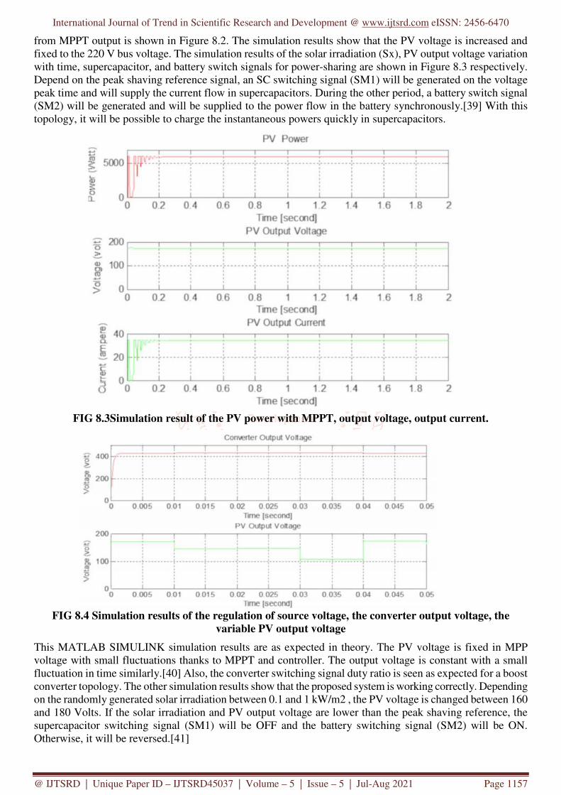
from MPPT output is shown in Figure 8.2. The simulation results show that the PV voltage is increased and fixed to the 220 V bus voltage. The simulation results of the solar irradiation (Sx), PV output voltage variation with time, supercapacitor, and battery switch signals for power-sharing are shown in Figure 8.3 respectively. Depend on the peak shaving reference signal, an SC switching signal (SM1) will be generated on the voltage peak time and will supply the current flow in supercapacitors. During the other period, a battery switch signal (SM2) will be generated and will be supplied to the power flow in the battery synchronously.[39] With this topology, it will be possible to charge the instantaneous powers quickly in supercapacitors.
FIG 8.3Simulation result of the PV power with MPPT, output voltage, output current.
FIG 8.4 Simulation results of the regulation of source voltage, the converter output voltage, the
variable PV output voltage
This MATLAB SIMULINK simulation results are as expected in theory. The PV voltage is fixed in MPP voltage with small fluctuations thanks to MPPT and controller. The output voltage is constant with a small fluctuation in time similarly.[40] Also, the converter switching signal duty ratio is seen as expected for a boost converter topology. The other simulation results show that the proposed system is working correctly. Depending on the randomly generated solar irradiation between 0.1 and 1 kW/m2 , the PV voltage is changed between 160 and 180 Volts. If the solar irradiation and PV output voltage are lower than the peak shaving reference, the supercapacitor switching signal (SM1) will be OFF and the battery switching signal (SM2) will be ON. Otherwise, it will be reversed.[41]

International Journal of Trend in Scientific Research and Development @ www.ijtsrd.com eISSN: 2456-6470
@ IJTSRD | Unique Paper ID – IJTSRD45037 | Volume – 5 | Issue – 5 | Jul-Aug 2021 Page 1158
FIGURE 8.5. Simulation results of the solar irradiation (Sx), PV output voltage variation with time,
supercapacitor, and battery switch signals for power-sharing
The supercapacitor modules are obtained by connecting five of the series and two of these series parts connected parallel in these simulations. So, I used 10 pcs in every module for the desired voltage and current. The simulation results of the supercapacitors in charge time from PV for the variable solar irradiation. The supercapacitor is charged dashed mode with time and the voltage is increased step by step and becomes constant with time according to the proposed method for every module. The charge current decreases from the maximum value to zero in approximately 400 s. The charge current can be changed depending on the weather conditions. The multiplication of this voltage and current gives the charged power in a supercapacitor, and the area under the curve gives the stored energy in the supercapacitor module.
Figure 8.6. The simulation results of the supercapacitors for the variable solar irradiation
The PV voltage changes in every five seconds steps depend on the solar irradiation. The DC bus voltage is increased up to 400 V voltage levels with the boost converter and MPPT+PID controller. The SC line voltage is equal to the bus voltage when the PV voltage is bigger than the reference voltage. The SC line voltage is equal to the charged level when the PV voltage is smaller than the reference voltage. In this state, the switch is off. The battery voltage is constant to the nominal voltage level with some small ripples.
International Journal of Trend in Scientific Research and Development @ www.ijtsrd.com eISSN: 2456-6470
@ IJTSRD | Unique Paper ID – IJTSRD45037 | Volume – 5 | Issue – 5 | Jul-Aug 2021 Page 1159
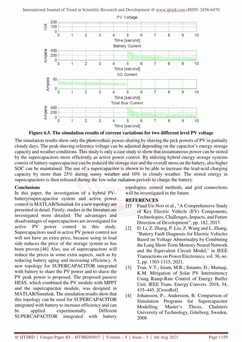
Figure 6.5. The simulation results of current variations for two different level PV voltage
The simulation results show only the photovoltaic power-sharing by shaving the pick powers of PV in partially cloudy days. The peak shaving reference voltage can be adjusted depending on the capacitor’s energy storage capacity and weather conditions. This study is only a case study to show that instantaneous power can be stored by the supercapacitors more efficiently as active power control. By utilizing hybrid energy storage systems consist of battery-supercapacitor can be reduced the storage size and the overall stress on the battery, also higher SOC can be maintained. The use of a supercapacitor is shown to be able to increase the lead-acid charging capacity by more than 25% during sunny weather and 10% in cloudy weather. The stored energy in supercapacitors is then released during the low solar radiation periods to charge the battery.
Conclusions
In this paper, the investigation of a hybrid PV–battery/supercapacitor system and active power control in MATLAB/Simulink for a new topology are presented in detail. Firstly, studies in the literature are investigated more detailed. The advantages and disadvantages of supercapacitors are investigated for active PV power control in this study. Supercapacitors used in active PV power control not will not have an extra price, because using in load side reduces the price of the storage system as has been proven.[46] Also, use of supercapacitors will reduce the prices in some extra aspects, such as by reducing battery aging and increasing efficiency. A new topology for SUPERCAPACITOR integrated with battery to share the PV power and to shave the PV peak power is proposed. The proposed passive HESS, which combined the PV module with MPPT and the supercapacitor module, was designed in MATLAB/Simulink. The simulation results show that this topology can be used for SUPERCAPACITOR integrated with battery to increase efficiency and can be applied experimentally. Different SUPERCAPACITOR integrated with battery
topologies, control methods, and grid connections will be investigated in the future.
REFERENCES
[1] Fuad Un-Noo et al., “A Comprehensive Study of Key Electric Vehicle (EV) Components, Technologies, Challenges, Impacts, and Future Direction of Development”, pp. 182, 2017.
[2] D. Li, Z. Zhang, P. Liu, Z. Wang and L. Zhang, "Battery Fault Diagnosis for Electric Vehicles Based on Voltage Abnormality by Combining the Long Short-Term Memory Neural Network and the Equivalent Circuit Model," in IEEE Transactions on Power Electronics, vol. 36, no. 2, pp. 1303-1315, 2021.
[3] Tran, V.T.; Islam, M.R.; Sutanto, D.; Muttaqi, K.M. Mitigation of Solar PV Intermittency Using Ramp-Rate Control of Energy Buffer Unit. IEEE Trans. Energy Convers. 2018, 34, 435–445. [CrossRef]
[4] Johansson, P.; Andersson, B. Comparison of Simulation Programs for Supercapacitor Modelling. Master’s Thesis, Chalmers University of Technology, Göteborg, Sweden, 2008