HYBRID DIELECTRIC RESONATOR ANTENNA FOR ULTRA HIGH...
37
HYBRID DIELECTRIC RESONATOR ANTENNA FOR ULTRA HIGH FREQUENCY BAND MUHAMMAD ISHAK BIN ABDUL SUKUR UNIVERSITI TEKNOLOGI MALAYSIA
Transcript of HYBRID DIELECTRIC RESONATOR ANTENNA FOR ULTRA HIGH...

HYBRID DIELECTRIC RESONATOR ANTENNA FOR ULTRA HIGH
FREQUENCY BAND
MUHAMMAD ISHAK BIN ABDUL SUKUR
UNIVERSITI TEKNOLOGI MALAYSIA

HYBRID DIELECTRIC RESONATOR ANTENNA FOR ULTRA HIGH
FREQUENCY BAND
MUHAMMAD ISHAK BIN ABDUL SUKUR
A thesis submitted in fulfilment of the
requirements for the award of the degree of
Master of Engineering (Electrical)
Faculty of Electrical Engineering
Universiti Teknologi Malaysia
OCTOBER 2015

T
I
O
N
This thesis is dedicated to my beloved father and mother, Abdul Sukur Bin Ismail
and Norjan Bee Binti Daud, my siblings, my families and my friends for their
support, morally and financially.
1
2
3
4

ii
ACKNOWLEDGEMENT
In the Name of Allah, Most Gracious, Most Merciful,
Alhamdulillah, thank you Allah, for your blessing and guidance to complete
my study. First and foremost, my highest gratitude goes to my project supervisor,
Professor Dr. Mohamad Kamal A. Rahim for his support and guidance. I am also
very thankful for the presence and knowledge of my co-supervisor, Dr. Noor Asniza
Binti Murad. Without these two pillars of support, I will not be able to finish this
thesis.
I warmly thank the entire Advanced Microwave and Antenna Laboratory
(AMAL - P18) members especially Dr. Huda, Dr. Bashir, Raimi, Hazmi, Nasrun,
Syazwan, Ezwan, Osman and Izni, for their help in multiple situations and the
beneficial discussions during the progress presentation meetings.
Finally, I am very grateful to my beloved parents, for their endless prayers,
love and encouragement. I wish to express my love and gratitude to other members
of my family, my brother and lovely sisters, for their supports and endless love,
through the duration of my studies.

iii
ABSTRACT
A hybrid Dielectric Resonator Antenna (DRA) design using the concept of the
Dielectric-Resonator-on-Patch (DRoP) is presented in this thesis. This design is
introduced to overcome the narrow bandwidth and big size drawbacks experienced
by the antennas in the UHF band applications. The hybrid DRA has the ability to
provide wide bandwidth while maintaining its compact structure. Firstly, two
antenna designs which are the aperture-coupled square microstrip patch antenna
(RMPA) and dielectric resonator antenna (RDRA) are presented to investigate the
characteristic of the antennas individually. Two different aperture shapes, rectangular
and circular are used to clarify the difference between them. Then, both antennas are
combined together into the hybrid DRA structure. All three antennas are designed
and optimized using Computer Simulation Technology (CST) microwave studio
software and the Taconic RF-35 is used as the substrate for the prototype fabrication.
The antenna performances such as the reflection coefficient magnitude (S11),
bandwidth, radiation pattern and gain are measured. In the RMPA design, both
configurations managed to obtain a compact size, with a reduction of more than 25%
compared to the reference antenna. On the other hand, by maintaining the size of the
DRA at 7cm × 7cm × 1.4cm, a wide bandwidth of around 30% is recorded using the
circular aperture in the RDRA design. The hybrid DRA combined both RMPA and
RDRA, resulting in wider bandwidth of 60%, from 0.77 to 1.43GHz with an average
gain of 3.4dBi. The dimension of the dielectric resonator antenna is compact, which
is 0.257λo and also low-profile with a height of 0.051λo.
iv
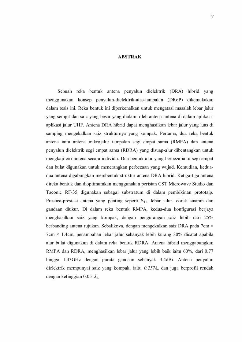
ABSTRAK
Sebuah reka bentuk antena penyalun dielektrik (DRA) hibrid yang
menggunakan konsep penyalun-dielektrik-atas-tampalan (DRoP) dikemukakan
dalam tesis ini. Reka bentuk ini diperkenalkan untuk mengatasi masalah lebar jalur
yang sempit dan saiz yang besar yang dialami oleh antena-antena di dalam aplikasi-
aplikasi jalur UHF. Antena DRA hibrid dapat menghasilkan lebar jalur yang luas di
samping mengekalkan saiz strukturnya yang kompak. Pertama, dua reka bentuk
antena iaitu antena mikrojalur tampalan segi empat sama (RMPA) dan antena
penyalun dielektrik segi empat sama (RDRA) yang disuap-alur dibentangkan untuk
mengkaji ciri antena secara individu. Dua bentuk alur yang berbeza iaitu segi empat
dan bulat digunakan untuk menerangkan perbezaan yang wujud. Kemudian, kedua-
dua antena digabungkan membentuk struktur antena DRA hibrid. Ketiga-tiga antena
direka bentuk dan dioptimumkan menggunakan perisian CST Microwave Studio dan
Taconic RF-35 digunakan sebagai substratum di dalam pembikinan prototaip.
Prestasi-prestasi antena yang penting seperti S11, lebar jalur, corak sinaran dan
gandaan diukur. Di dalam reka bentuk RMPA, kedua-dua konfigurasi berjaya
menghasilkan saiz yang kompak, dengan pengurangan saiz lebih dari 25%
berbanding antena rujukan. Sebaliknya, dengan mengekalkan saiz DRA pada 7cm ×
7cm × 1.4cm, penambahan lebar jalur sebanyak lebih kurang 30% dicatat apabila
alur bulat digunakan di dalam reka bentuk RDRA. Antena hibrid menggabungkan
RMPA dan RDRA, menghasilkan lebar jalur yang lebih baik iaitu 60%, dari 0.77
hingga 1.43GHz dengan purata gandaan sebanyak 3.4dBi. Antena penyalun
dielektrik mempunyai saiz yang kompak, iaitu 0.257λo dan juga berprofil rendah
dengan ketinggian 0.051λo.

v
TABLE OF CONTENTS
CHAPTER TITLE PAGE
DECLARATION Error! Bookmark not defined.
DEDICATION i
ACKNOWLEDGEMENT ii
ABSTRACT iii
ABSTRAK vi
TABLE OF CONTENTS v
LIST OF TABLES xii
LIST OF FIGURES xv
LIST OF ABBREVIATIONS xxi
LIST OF SYMBOLS xxii
LIST OF APPENDICES xxiii
1 INTRODUCTION 1
1.1 Background of the study 1
1.2 Problem Statement 2
1.3 Research Objective 4
1.4 Scope of Work 4
1.5 Thesis Outlines 5
2 LITRATURE REVIEW 7
2.1 Introduction 7
2.2 Microstrip Patch Antenna 8

vi
2.2.1 Microstrip Patch Antenna with Microstrip
Feed Line 9
2.2.2 Microstrip Patch Antenna with Coaxial
Probe Feed 10
2.2.3 Microstrip Patch Antenna with Aperture
Coupling 12
2.2.4 Microstrip Patch Antenna with Proximity
Coupling 14
2.2.5 Microstrip Patch Antenna with Coplanar
Waveguide Feed 17
2.2.6 Summary of the Microstrip Patch Antenna 18
2.3 Dielectric Resonator Antenna 21
2.4 Shapes of the Dielectric Resonator Antenna 22
2.4.1 The Rectangular Dielectric Resonator
Antenna 23
2.5 Compact Dielectric Resonator Antenna Design 25
2.5.1 High Permittivity Materials 25
2.5.2 Metal Loading 27
2.5.3 Shape Modification of the Dielectric
Resonator Antenna 28
2.5.4 Summary of the Compact Dielectric
Resonator Antenna Design 29
2.6 Wideband Dielectric Resonator Antenna Design 30
2.6.1 Low Permittivity Materials 30
2.6.2 Stacking Multiple Dielectric Resonator
Antennas 31
2.6.3 Dielectric Resonator Antenna's Shape
Modification 32
2.6.4 Summary of the Wideband Dielectric
Resonator Antenna Design 34
2.7 Hybrid Dielectric Resonator Antenna Design 35
2.7.1 Hybrid Dielectric Resonator with Radiating
Feeder 35
vii
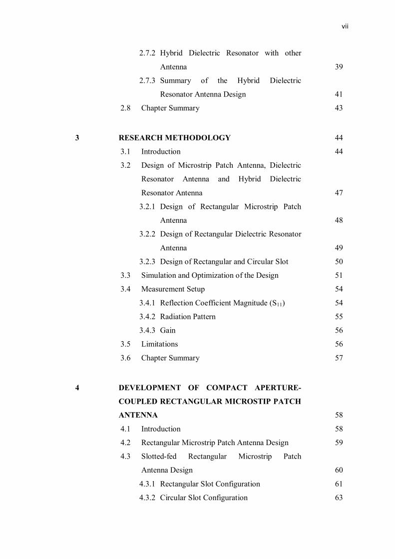
2.7.2 Hybrid Dielectric Resonator with other
Antenna 39
2.7.3 Summary of the Hybrid Dielectric
Resonator Antenna Design 41
2.8 Chapter Summary 43
3 RESEARCH METHODOLOGY 44
3.1 Introduction 44
3.2 Design of Microstrip Patch Antenna, Dielectric
Resonator Antenna and Hybrid Dielectric
Resonator Antenna 47
3.2.1 Design of Rectangular Microstrip Patch
Antenna 48
3.2.2 Design of Rectangular Dielectric Resonator
Antenna 49
3.2.3 Design of Rectangular and Circular Slot 50
3.3 Simulation and Optimization of the Design 51
3.4 Measurement Setup 54
3.4.1 Reflection Coefficient Magnitude (S11) 54
3.4.2 Radiation Pattern 55
3.4.3 Gain 56
3.5 Limitations 56
3.6 Chapter Summary 57
4 DEVELOPMENT OF COMPACT APERTURE-
COUPLED RECTANGULAR MICROSTIP PATCH
ANTENNA 58
4.1 Introduction 58
4.2 Rectangular Microstrip Patch Antenna Design 59
4.3 Slotted-fed Rectangular Microstrip Patch
Antenna Design 60
4.3.1 Rectangular Slot Configuration 61
4.3.2 Circular Slot Configuration 63
viii
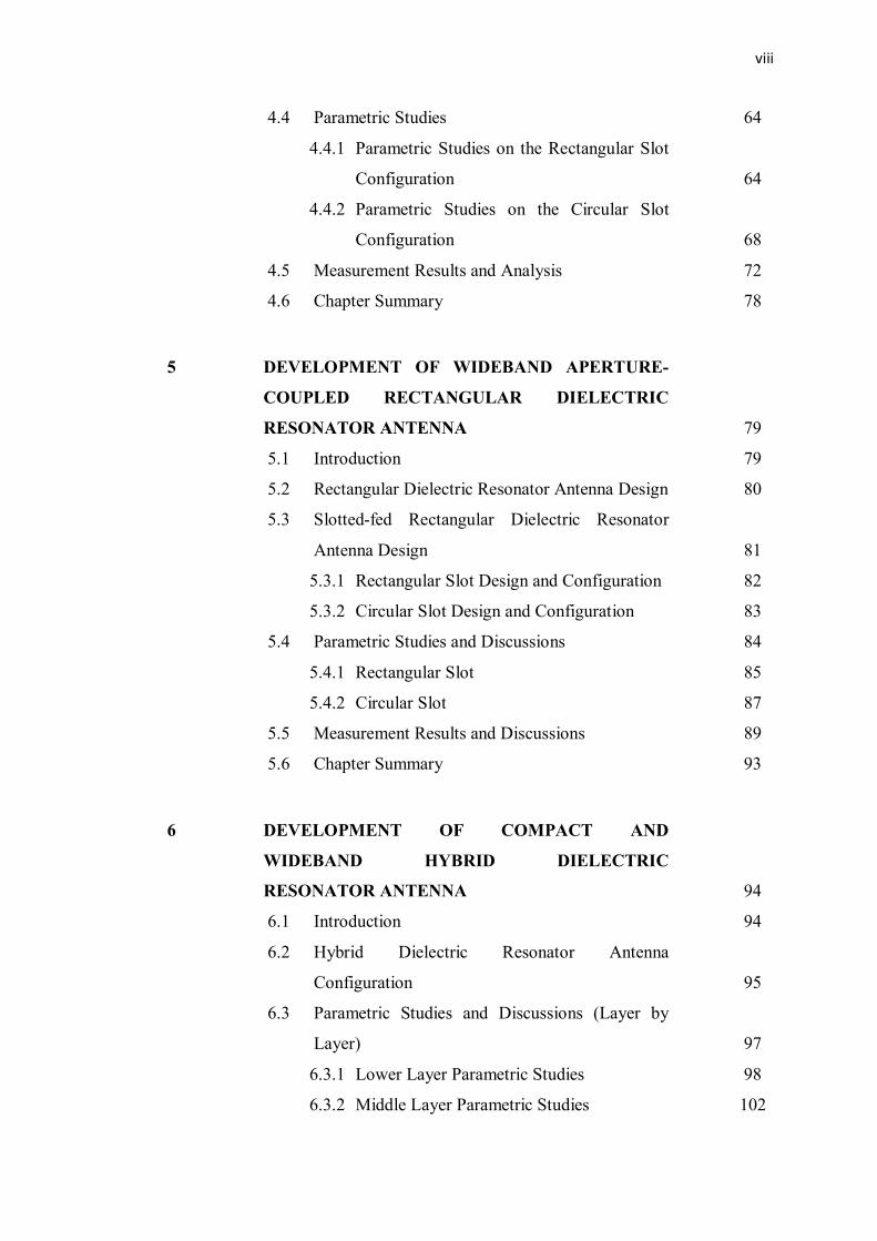
4.4 Parametric Studies 64
4.4.1 Parametric Studies on the Rectangular Slot
Configuration 64
4.4.2 Parametric Studies on the Circular Slot
Configuration 68
4.5 Measurement Results and Analysis 72
4.6 Chapter Summary 78
5 DEVELOPMENT OF WIDEBAND APERTURE-
COUPLED RECTANGULAR DIELECTRIC
RESONATOR ANTENNA 79
5.1 Introduction 79
5.2 Rectangular Dielectric Resonator Antenna Design 80
5.3 Slotted-fed Rectangular Dielectric Resonator
Antenna Design 81
5.3.1 Rectangular Slot Design and Configuration 82
5.3.2 Circular Slot Design and Configuration 83
5.4 Parametric Studies and Discussions 84
5.4.1 Rectangular Slot 85
5.4.2 Circular Slot 87
5.5 Measurement Results and Discussions 89
5.6 Chapter Summary 93
6 DEVELOPMENT OF COMPACT AND
WIDEBAND HYBRID DIELECTRIC
RESONATOR ANTENNA 94
6.1 Introduction 94
6.2 Hybrid Dielectric Resonator Antenna
Configuration 95
6.3 Parametric Studies and Discussions (Layer by
Layer) 97
6.3.1 Lower Layer Parametric Studies 98
6.3.2 Middle Layer Parametric Studies 102

ix
6.4 Parametric Studies (All Layers are Present) 104
6.5 Proposed Hybrid Dielectric Resonator Antenna
Operating at Different Range of Frequencies 113
6.6 Measurement Results and Discussions 118
6.7 Chapter Summary 122
7 CONCLUSIONS AND FUTURE WORKS 124
7.1 Conclusion 124
7.2 Contributions of the Project 126
7.3 Future Works and Recommendations 127
REFERENCES 128
Appendices A - D 136-145
x
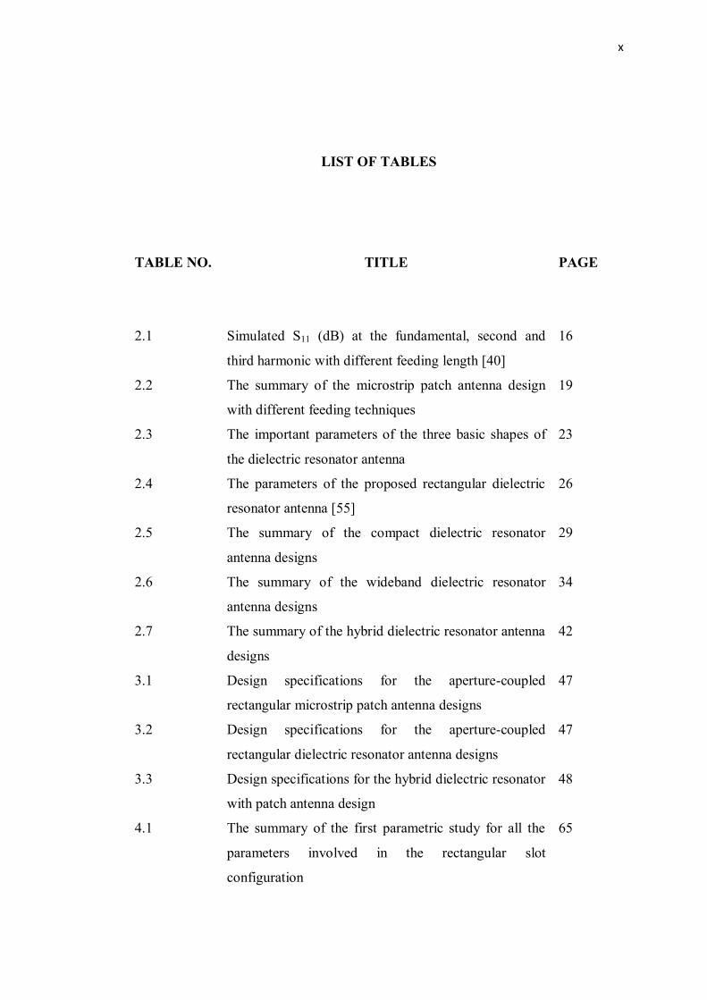
LIST OF TABLES
TABLE NO. TITLE
PAGE
2.1 Simulated S11 (dB) at the fundamental, second and
third harmonic with different feeding length [40]
16
2.2 The summary of the microstrip patch antenna design
with different feeding techniques
19
2.3 The important parameters of the three basic shapes of
the dielectric resonator antenna
23
2.4 The parameters of the proposed rectangular dielectric
resonator antenna [55]
26
2.5 The summary of the compact dielectric resonator
antenna designs
29
2.6 The summary of the wideband dielectric resonator
antenna designs
34
2.7 The summary of the hybrid dielectric resonator antenna
designs
42
3.1 Design specifications for the aperture-coupled
rectangular microstrip patch antenna designs
47
3.2 Design specifications for the aperture-coupled
rectangular dielectric resonator antenna designs
47
3.3 Design specifications for the hybrid dielectric resonator
with patch antenna design
48
4.1 The summary of the first parametric study for all the
parameters involved in the rectangular slot
configuration
65
xi
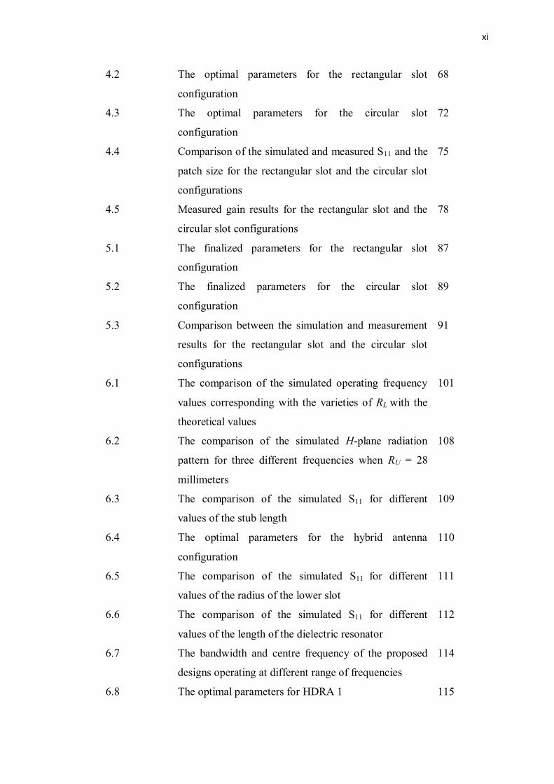
4.2 The optimal parameters for the rectangular slot
configuration
68
4.3 The optimal parameters for the circular slot
configuration
72
4.4 Comparison of the simulated and measured S11 and the
patch size for the rectangular slot and the circular slot
configurations
75
4.5 Measured gain results for the rectangular slot and the
circular slot configurations
78
5.1 The finalized parameters for the rectangular slot
configuration
87
5.2 The finalized parameters for the circular slot
configuration
89
5.3 Comparison between the simulation and measurement
results for the rectangular slot and the circular slot
configurations
91
6.1 The comparison of the simulated operating frequency
values corresponding with the varieties of RL with the
theoretical values
101
6.2 The comparison of the simulated H-plane radiation
pattern for three different frequencies when RU = 28
millimeters
108
6.3 The comparison of the simulated S11 for different
values of the stub length
109
6.4 The optimal parameters for the hybrid antenna
configuration
110
6.5 The comparison of the simulated S11 for different
values of the radius of the lower slot
111
6.6 The comparison of the simulated S11 for different
values of the length of the dielectric resonator
112
6.7 The bandwidth and centre frequency of the proposed
designs operating at different range of frequencies
114
6.8 The optimal parameters for HDRA 1 115

xii
6.9 The optimal parameters for HDRA 2 116
6.10 The optimal parameters for HDRA 3 117
6.11 Summary of the simulated and measured reflection
coefficient magnitude of the proposed design
119
6.12 Measured gain for the hybrid dielectric resonator
antenna configuration
121
6.13 The comparison of the proposed hybrid dielectric
resonator antenna with similar designs
123
xiii
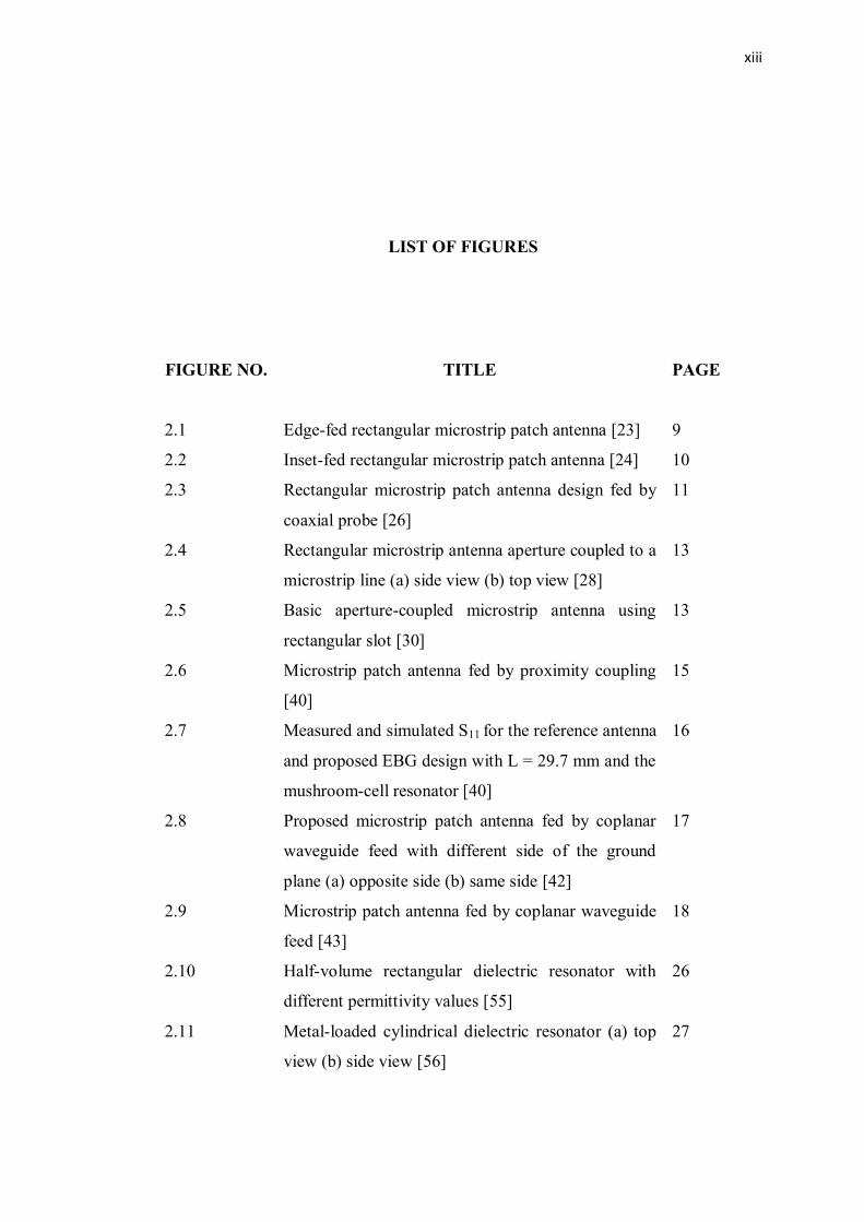
LIST OF FIGURES
FIGURE NO. TITLE
PAGE
2.1 Edge-fed rectangular microstrip patch antenna [23] 9
2.2 Inset-fed rectangular microstrip patch antenna [24] 10
2.3 Rectangular microstrip patch antenna design fed by
coaxial probe [26]
11
2.4 Rectangular microstrip antenna aperture coupled to a
microstrip line (a) side view (b) top view [28]
13
2.5 Basic aperture-coupled microstrip antenna using
rectangular slot [30]
13
2.6 Microstrip patch antenna fed by proximity coupling
[40]
15
2.7 Measured and simulated S11 for the reference antenna
and proposed EBG design with L = 29.7 mm and the
mushroom-cell resonator [40]
16
2.8 Proposed microstrip patch antenna fed by coplanar
waveguide feed with different side of the ground
plane (a) opposite side (b) same side [42]
17
2.9 Microstrip patch antenna fed by coplanar waveguide
feed [43]
18
2.10 Half-volume rectangular dielectric resonator with
different permittivity values [55]
26
2.11 Metal-loaded cylindrical dielectric resonator (a) top
view (b) side view [56]
27

xiv
2.12 Shape-modified cylindrical dielectric resonator
antenna [59]
28
2.13 Strip-fed rectangular dielectric resonator antenna
[60]
31
2.14 Stacked cylindrical dielectric resonator antenna (a)
top view (b) side view [61]
32
2.15 Flipped staired pyramid dielectric resonator antenna
(a) top view (b) side view [65]
33
2.16 Hybrid dielectric resonator antenna with a radiating
T-shaped feed line (a) top view (b) side view [66]
36
2.17 Hybrid dielectric resonator antenna with a radiating
coplanar waveguide (a) top view (b) side view [67]
37
2.18 Hybrid dielectric resonator antenna with a radiating
slot (a) top view (b) side view [68]
38
2.19 The cross-sectional of the hybrid dielectric resonator
with the monopole antenna [69]
40
2.20 The side view of the hybrid dielectric resonator with
the patch antenna [6]
41
3.1 Flow chart of the methods used 46
3.2 Geometry of the rectangular DRA [72] 49
3.3 Slot configuration in simulation (a) material defined
as vacuum (b) cut-out from the ground plane
52
3.4 Side view of the slot-coupled feed substrate 52
3.5 Parametric study setup box for different values of RL 53
3.6 Rohde and Schwartz network analyzer 54
3.7 The radiation pattern and gain measurement setup 55
4.1 The rectangular microstrip patch antenna (a) top
view (b) side view
59
4.2 The configuration of the proposed aperture-coupled
rectangular microstrip patch antenna
61
4.3 The configuration of the rectangular slot of the patch
antenna (a) top view (b) rear view (c) patch antenna
and its substrate
62
xv
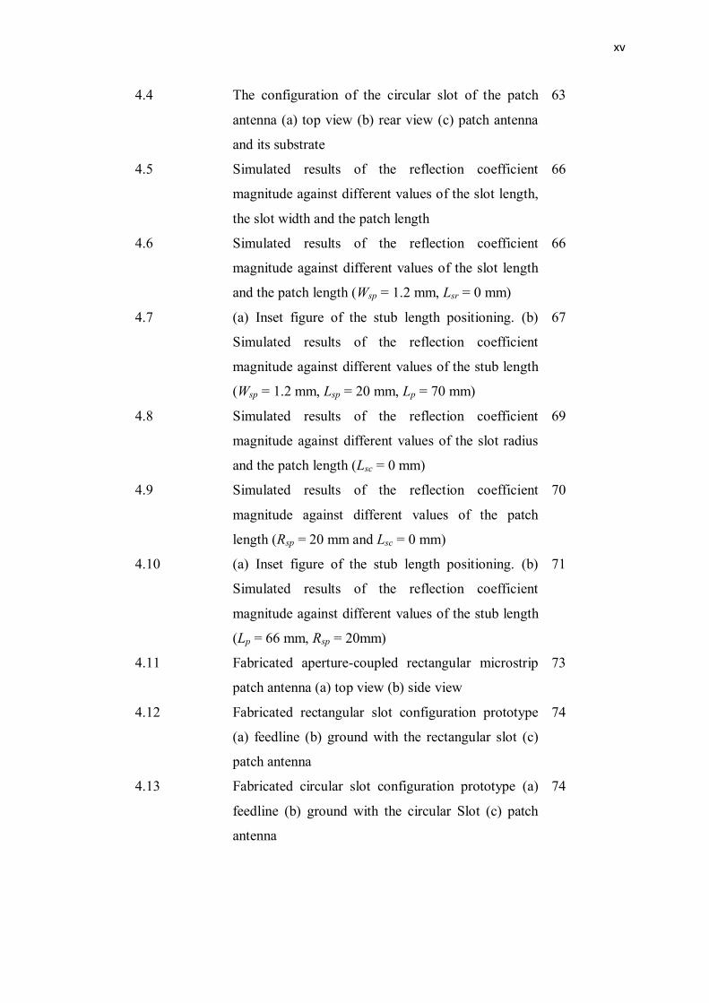
4.4 The configuration of the circular slot of the patch
antenna (a) top view (b) rear view (c) patch antenna
and its substrate
63
4.5 Simulated results of the reflection coefficient
magnitude against different values of the slot length,
the slot width and the patch length
66
4.6 Simulated results of the reflection coefficient
magnitude against different values of the slot length
and the patch length (Wsp = 1.2 mm, Lsr = 0 mm)
66
4.7 (a) Inset figure of the stub length positioning. (b)
Simulated results of the reflection coefficient
magnitude against different values of the stub length
(Wsp = 1.2 mm, Lsp = 20 mm, Lp = 70 mm)
67
4.8 Simulated results of the reflection coefficient
magnitude against different values of the slot radius
and the patch length (Lsc = 0 mm)
69
4.9 Simulated results of the reflection coefficient
magnitude against different values of the patch
length (Rsp = 20 mm and Lsc = 0 mm)
70
4.10 (a) Inset figure of the stub length positioning. (b)
Simulated results of the reflection coefficient
magnitude against different values of the stub length
(Lp = 66 mm, Rsp = 20mm)
71
4.11 Fabricated aperture-coupled rectangular microstrip
patch antenna (a) top view (b) side view
73
4.12 Fabricated rectangular slot configuration prototype
(a) feedline (b) ground with the rectangular slot (c)
patch antenna
74
4.13 Fabricated circular slot configuration prototype (a)
feedline (b) ground with the circular Slot (c) patch
antenna
74
xvi
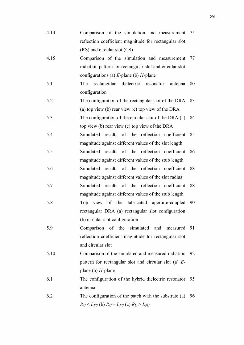
4.14 Comparison of the simulation and measurement
reflection coefficient magnitude for rectangular slot
(RS) and circular slot (CS)
75
4.15 Comparison of the simulation and measurement
radiation pattern for rectangular slot and circular slot
configurations (a) E-plane (b) H-plane
77
5.1 The rectangular dielectric resonator antenna
configuration
80
5.2 The configuration of the rectangular slot of the DRA
(a) top view (b) rear view (c) top view of the DRA
83
5.3 The configuration of the circular slot of the DRA (a)
top view (b) rear view (c) top view of the DRA
84
5.4 Simulated results of the reflection coefficient
magnitude against different values of the slot length
85
5.5 Simulated results of the reflection coefficient
magnitude against different values of the stub length
86
5.6 Simulated results of the reflection coefficient
magnitude against different values of the slot radius
88
5.7 Simulated results of the reflection coefficient
magnitude against different values of the stub length
88
5.8 Top view of the fabricated aperture-coupled
rectangular DRA (a) rectangular slot configuration
(b) circular slot configuration
90
5.9 Comparison of the simulated and measured
reflection coefficient magnitude for rectangular slot
and circular slot
91
5.10 Comparison of the simulated and measured radiation
pattern for rectangular slot and circular slot (a) E-
plane (b) H-plane
92
6.1 The configuration of the hybrid dielectric resonator
antenna
95
6.2 The configuration of the patch with the substrate (a)
RU < LPU (b) RU = LPU (c) RU > LPU
96
xvii
6.3 The complete configuration of the proposed hybrid
antenna design (a) lower layer rear view (b) lower
layer top view (c) middle layer top view (d) top layer
97
6.4 The related parameters involved in the lower layer
parametric study
98
6.5 Simulated results of the reflection coefficient
magnitude against different values of the radius of
the lower slot (LU = 0 mm)
99
6.6 Simulated results of the reflection coefficient
magnitude against different values of the stub length
(RL = 35 mm)
99
6.7 Simulated results of the reflection coefficient
magnitude against different values of the radius of
the lower slot (LU = 5.56 mm)
100
6.8 The related parameters involved in the middle layer
parametric study
102
6.9 Simulated results of the reflection coefficient
magnitude against different values of the length of
the patch (LU = 5.56 mm, RL = 35 mm, RU = 0 mm)
103
6.10 Simulated results of the reflection coefficient
magnitude against different values of the radius of
the upper slot (LU = 5.56 mm, RL = 35 mm, LPU = 67
mm)
104
6.11 Simulated results of the reflection coefficient
magnitude against different values of the radius of
the upper slot (LU = 5.56 mm, RL = 35 mm, LPU = 67
mm, LD = 70 mm)
105
6.12 Simulated results of the reflection coefficient
magnitude when RU = 28 mm
106
6.13 Simulated results of the H-plane radiation pattern
when RU = 28 millimeters (a) at 0.58 GHz (b) at 1.40
GHz (c) at 1.84 GHz
107
xviii
6.14 Simulated results of the reflection coefficient
magnitude against different values of the stub length
(RU = 36 mm, RL = 35 mm, LPU = 67 mm, LD = 70
mm)
108
6.15 Simulated results of the reflection coefficient
magnitude against different values of the radius of
the lower slot
111
6.16 Simulated results of the reflection coefficient
magnitude against different values of the length of
the dielectric resonator
112
6.17 The reflection coefficient magnitude for the hybrid
dielectric resonator antenna operating at different
range of frequencies
113
6.18 The fabricated hybrid dielectric resonator antenna
prototype (a) lower layer rear view (b) lower layer
top view (c) middle layer top view (d) hybrid
antenna top view (e) hybrid antenna rear view
118
6.19 The comparison between the simulated and the
measured reflection coefficient magnitude of the
proposed design
119
6.20 The comparison between the simulated and the
measured radiation pattern of the proposed design
120
6.21 The comparison between the measured reflection
coefficient magnitude of the three proposed designs
122
xix
LIST OF ABBREVIATIONS
UHF - Ultra-High Frequency
RFID - Radio Frequency Identification
DRA - Dielectric Resonator Antenna
DRoP - Dielectric-Resonator-on-Patch
CST - Computer Simulation Technology
UV - Ultra Violet
DR - Dielectric Resonator
RDRA - Rectangular Dielectric Resonator Antenna
CDRA - Cylindrical Dielectric Resonator Antenna
HDRA - Hybrid Dielectric Resonator Antenna
MPA - Microstrip Patch Antenna
RMPA - Rectangular Microstrip Patch Antenna
CPW - Coplanar Waveguide
FR-4 - Fire Retardant Type 4
VSWR - Voltage Standing Wave Ratio
CP - Circular Polarization
RHCP - Right Hand Circular Polarization
LHCP - Left Hand Circular Polarization
DWM - Dielectric Waveguide Model
FDTD - Finite Difference Time Domain
TE - Transverse Electric
SMA - Sub Miniature version A
PVA - Poly-Vinyl Acetate

xx
LIST OF SYMBOLS
E - Electric Field
H - Magnetic Field
εr - Relative Permittivity
εreff - Effective Relative Permittivity
εo - Free-space Permittivity (8.85 × 10⁻¹²
F/m)
λo - Free-space Wavelength
λg - Guided Wavelength
fo - Operating Frequency
ΔL - Extended Incremental Length of the Patch
c - Speed of Light (3 × 10⁸ m/s)
kx - Wave Number along x-axis
ky - Wave Number along y-axis
kz - Wave Number along z-axis
Ko - Wave Number in Free-space
h, d - Height
W, b - Width
r - Radius
L, a - Length
xxi
LIST OF APPENDICES
APPENDIX TITLE PAGE
A List of author's publication (Conference) 136
B Fabrication process (example: microstrip feed line) 137
C Simulated surface current distribution of the
Proposed designs
140
D Simulated 3-D radiation pattern of the proposed
designs
143
CHAPTER 1
INTRODUCTION
1.1 Background of the study
The Ultra-High Frequency (UHF) band is being used in various applications
such as television transceiver systems, walkie-talkies, and radio frequency
identifications (RFIDs). Ranging from 300 Megahertz up to 3 Gigahertz, this
particular band mostly used in two-ways radio and public safety communications.
They do not interfere other local transmissions since they are transmitted in a limited
range, and relied on a line-of-sight distance. The conventional antennas used in these
applications are patch, monopole and dipole antennas.
The dielectrics were first used in oscillator or filter designs, whereby they were
enclosed in metal cavities to prevent radiation and maintaining high quality factor
(Q-factor). In order to create an efficient radiator, the shield was removed, causing
the Q-factor to be reduced and dependant on the permittivity of the dielectric, and the
dielectric was properly fed to excite suitable mode. The dielectric resonator antennas
have a long history of development, almost three decades, which started in 1983
when Long, McAllister and Shen introduced a cylindrical dielectric cavity antenna
[1].
2
The dielectric resonator antenna (DRA) has several advantages over the
conventional radiating antenna such as small size, low cost and good temperature
stability [2]. In 1981, Birand and Gelsthorpe used the DRs as antenna elements by
proposing the linearly polarized array dielectric radiators structure [3]. The DRA is
normally fabricated using a material with a high dielectric constant. It can be
incorporated with multiple feeding mechanisms such as the coaxial probe, the
microstrip feed line, the aperture coupling source, and the coplanar waveguide
(CPW) [4].
Furthermore, the DRA consists of various geometries such as rectangular,
cylindrical, hemispherical, circular, and triangular. The resonant frequency of the
DRA is highly dependent on the dimension and the shape of the DRA, as well as the
permittivity of the material. Numbers of works were carried out on the types of
DRAs such as the compact DRAs, the wideband DRAs, the DRA arrays and the
hybrid DRAs. The dielectric-resonator-on-patch (DRoP) is one of the existing
concept of the hybrid DRAs introduced by Esselle in 2001 [5] before it is
experimentally carried out in 2005 [6]. DRoP is a structure with a dielectric
resonator placed symmetrically on top of a patch antenna. In other words, DRoP is a
combination of two different antennas with less space consuming yet providing a
wider bandwidth.
1.2 Problem Statement
Nowadays, the communication applications at UHF bands developing rapidly,
especially at the lower region of the UHF band. These ranges of frequencies are
used for several applications such as walkies-talkies, digital television, UHF RFIDs
and two-ways radio. The signal can travel farther by operating at lower frequencies
but its obstacle penetration level is low, which is suitable for terrestrial applications
as mentioned before where signal penetration is not critical.
3
Antennas such as patch, monopole and dipole antennas are normally used in
UHF band applications. The main drawbacks of these antennas are having a huge
size of a half-wavelength or quarter-wavelength, in regards of their operating
frequencies. For example, at 0.9 GHz, the conventional patch antennas and the
dipole antennas have a dimension of 166.7 milimeters (half-wavelength) and the
monopole antennas have a dimension of 83.8 milimeters (quarter-wavelength).
Monopole antennas are more desirable since it halved the dimension of its
counterparts, the patch and dipole antennas. In addition, the bandwidth of these
antennas is narrow, which is less than 1% for the patch antennas and less than 10%
for the dipole and monopole antennas.
The Dielectric Resonator Antenna (DRA) can obtain wide bandwidth while
maintaining its compact size. The dimension of the structure is highly dependent on
the dielectric constant of the material, with a wide range between 4 and 100.
However, by using the materials with high dielectric constant, it will result in a
narrower bandwidth of the DRA. So, in order to achieve both features, the DRA is
combined with other radiating elements such as slot and patch antennas. Thus, a
hybrid design which offers wider bandwidth and miniaturization can be developed.
A quarter-wavelength hybrid DRA is proposed in [5] and [6] which operate at 5
GHz. The design achieved a wide bandwidth of 23.5%. By doing some
modification, this structure can maintain its size eventhough it operates at lower
frequency and its bandwidth can be enhanced.
Wider bandwidth will lead to a cost reduction in the antenna design since a
single wideband antenna can be used instead of multiple narrowband antennas. Most
of the antennas in the UHF bands cannot achieve wide bandwidth due to the usage of
the material with high dielectric constant without the addition of the bandwidth
enhancement technique.
4
1.3 Research Objective
The objectives of this research are:
1. To develop a compact aperture-coupled rectangular microstrip patch
antenna (RMPA) using the rectangular and circular slots.
2. To develop a wideband aperture-coupled rectangular dielectric
resonator antenna (RDRA) using the rectangular and circular slots.
3. To integrate the aperture-coupled RDRA and RMPA into a compact
and wideband hybrid dielectric resonator antenna for UHF band.
1.4 Scope of Work
The scope began with the information gathering process through the literature
review on the related topics. The ultra-high frequncy (UHF) band is from 300 MHz
up to 3 GHz, and the applications at the middle range of this band (800 MHz to 1.4
GHz) is aimed in this work. The previous published design of the rectangular
microstrip patch antennas, rectangular DRAs, compact DRAs, wideband DRAs and
the hybrid DRAs are reviewed to obtain the best solution to achieve the objectives.
It is crucial to find out the basic information on the antenna designs, and identifying
the limitations and the expected results of the proposed designs. The main objective
is to design a hybrid DRA consists of the DRA and microstrip patch antenna to
obtain wide bandwidth without increasing the dimension of the antenna
unnecessarily, and the dielectric-resonator-on-patch (DRoP) concept is found to be
the most suitable solution. In order to fully understand this concept, the aperture-
coupled MPAs and DRAs are reviewed and studied. The theoretical dimensions of
the antennas were also obtained from the literature review.
5
Computer Simulation Technology (CST) Microwave Studio is used to design
and simulate the proposed antenna. Simulation results are analyzed in term of the
reflection coefficient magnitude (S11), the bandwidth, the gain, and the radiation
pattern and optimum dimensions are obtained by doing optimization and parametric
studies. The effect of changing the dimensions towards the resonance frequency are
observed during the process. The final design with the optimum dimensions were
fabricated by using photolitography process.
Once the prototypes are fabricated, measurement is carried out using vector
network analyzer setup. The parameters such as the reflection coefficient magnitude
(S11), the bandwidth, the gain, the radiation pattern were measured using the vector
network analyzer and anechoic chamber. The differences that occured between the
simulated and the measured results were compared and discussed.
1.5 Thesis Outlines
There are seven chapters in this thesis. Chapter 1 introduces the overview of
the project, the problem statements, the objectives and the scope of the project. Two
main problems were identified, where the antennas employed in the ultra-high
frequency band applications have narrow bandwidth and excessive dimensions. The
scope of work is briefly explained.
Chapter 2 provides critical explanations on the different feeding techniques for
the MPA designs, the RDRA antennas, and useful equations to calculate the
dimensions of the RMPA and RDRA. In addition, the different methods to enhance
the bandwidth of DRA and to achieve DRAs miniaturisation are presented. Hybrid
DRAs with radiating elements are also reviewed.
6
Chapter 3 discusses on methodology and project designs implemented in this
work. In this chapter, the simulation, fabrication and measurement process are
illustrated. The methods and techniques used are explained to show the technical
flow of the project. Besides that, the design specifications of the proposed designs
and the limitations during the whole period of this project are also stated.
Chapter 4 presents the configuration and the design of the compact rectangular
microstrip patch antenna, coupled by a slot. Two different shapes of the slot, the
rectangular slot and the circular slot are used and the differences that occurred in the
important paremeters such as the reflection coefficient magnitude (S11), gain and
radiation patterns between the two configurations are discussed.
Chapter 5 explains the wideband rectangular dielectric resonator antenna
design, using the rectangular and the circular slot. The differences that occurred in
the important parameters such as the reflection coefficient magnitude (S11), gain and
radiation patterns between the two configurations are discussed.
Chapter 6 describes the design process of the proposed wideband and compact
hybrid dielectric resonator with patch antenna, consists of the rectangular microstrip
patch antenna and rectangular dielectric resonator antenna. In this chapter, the
simulated and fabricated results such as the reflection coefficient magnitude (S11),
gain and radiation patterns of the proposed designs are presented.
Chapter 7 concludes the thesis by stating the contributions of the project and
the suggested possible solutions suitable for the optimization of the proposed design
in the future. The proposed hybrid antenna is compared with other related works to
proof the capability of the hybrid antenna in achieving wide bandwidth while
maintaining its size.
128
REFERENCES
1. Long, S. A., McAllister. M. W., and Shen, L. C. The Resonant Cylindrical
Dielectric Cavity Antenna. IEEE Transactions on Antennas and
Propagation. 1983. AP-31 (3): 406-412.
2. Glisson, A. W., Kajfez, D., and James, J. Evaluation of Modes in Dielectric
Resonators Using a Surface Integral Equation Formulation. IEEE
Transactions on Microwave Theory and Techniques. 1983. MTT-31 (12):
1023-1029.
3. Birand, M. T. and Gelsthorpe, R. V. Experimental Millimetri Array using
Dielectric Radiators fed by Means of Dielectric Waveguide. Electronic
Letters. 1981. 17 (18): 633-635.
4. Petosa, A. and Ittipiboon, A. Dielectric Resonator Antennas: A Historical
Review and the Current State of the Art. IEEE Antennas and Propagation
Magazine. 2010. 52 (5): 91-116.
5. Esselle, K. P. A Dielectric-Resonator-on-Patch (DRoP) Antenna for
Broadband Wireless Applications: Concept and Results. A Dual-band
Compact Hybrid Resonator Antenna. IEEE Antennas and Propagation
Society International Symphosium. July 8-13, 2001. Boston, USA: IEEE.
2001. 2: 22-25.
6. Esselle, K. P. and Bird, T. S. A Hybrid-resonator Antenna: Experimental
Results. Compact Cylindrical Sector Dielectric Resonator Antennas. IEEE
Transactions on Antennas and Propagation. February 2005. 53 (2): 870-871.
7. Deschamps, G. A. Microstrip Microwave Antennas. Third USAF
Symphosium on Antennas. 1953.
8. Gutton, H. and Baissinot, G. Flat Aerial for Ultra High Frequencies. French
Patent No. 703, 113. 1955.
129
9. Munson, R. E. Conformal Microstrip Antennas and Microstrip Phased
Arrays. IEEE Transactions on Antennas and Propagation. January 1974.
22(1): 74-78.
10. Howell, J. Q. Microstrip Antennas. Antennas and Propagation Society
International Symphosium. December 1972. Hampton, USA: IEEE. 1972. 10:
177-180.
11. Ramesh, G., Prakash, B., Inder, B., and Ittipiboon, A. Microstrip Antenna
Design Handbook. Norwood, Massachusetts, USA: Artech House. 2001.
12. Balanis, C. A. Antenna Theory: Analysis and Design. Third Edition.
Hoboken, New Jersey, USA: John Wiley and Sons Inc. 2005.
13. Liu, X., Chen, Y., Jiao, Y., and Zhang, F. Conformal Low-profile E-shaped
Patch Antenna with Enequal Thickness Substrate. IEEE International
Symposium on Microwave, Antenna, Propagation, and EMC Technologies
for Wireless Communication. August 16-17, 2007. Hangzhou, China: IEEE.
2007. 624-627.
14. Singh, C. and Gangwar, R. P. S. Design and Analysis of a Compact Low Cost
Patch Antenna for Different Wireless Operations. International Coference on
Emerging Trends in Networks and Computer Communications (ETNCC).
April 22-24, 2011. Udaipur, India: IEEE. 2011. 18-22.
15. Stoeckle, A., Lutz, S., Talai, A., and Fischer, G. A New Approach for a Dual-
polarized Low Cost Patch Antenna with Low Cross-polarization, High
Bandwidth and High Isolation. Topical Conference on Antennas and
Propagation in Wireless Communications (APWC). August 3-9, 2014. Palm
Beach, Netherlands: IEEE. 2014. 357-360.
16. Yu, D., Liu, W. L., and Zhang, Z. H. Simple Structure Multiband Patch
Antenna with Three Slots. International Conference on Microwave and
Milimeter Wave Technology (ICMMT). May 5-8, 2012. Shenzhen, China:
IEEE. 2012. 1-3.
17. Clenet, M. and Shafai, L. Multiple Resonances and Polarisations of U-slot
Patch Antenna. Electronic Letters. January 1999. 35 (2): 101-103.
18. Ray, G. L., Himdi, M., and Daniel, J. P. Frequency Agile Slot-fed Patch
Antenna. Electronic Letters. January 1996. 32 (1): 2-3.
19. Kelothu, B., Subhashini, K. R., and Manohar, G. L. A Compact High-gain
Microstrip Patch Antenna for Dual Band WLAN Apllications. Students
130
Conference on Engineering and Systems (SCES). March 16-18, 2012.
Allahabad, India: IEEE. 2012. 1-5.
20. Shah, M., Suaidi, M. K., Aziz, M. Z. A. A., Rose, M. R. C., Kadir, M. F. A.,
Ja'afar, A. S., Sidek, M., and Rahim, M. K. A. Dual Polarization Microstrip
Patch Array Antenna. International Symphosium on Telecommunication
(IST). August 27-28, 2008. Tehran, Iran: IEEE. 2008. 116-119.
21. Wang, J., Fralich, R., Wu, C., and Litva, J. Multifunctional Aperture Coupled
Stack Patch Antenna. Electronic Letters. December 1990. 26 (25): 2067-
2068.
22. Kordalivand, A. M. and Rahman, T. A. Broadband Modified Rectangular
Micro-strip Patch Antenna using Stepped Cut at Four Corners Method.
Progress In Electromagnetic Research. March 2013. 137: 599-619.
23. Li-ping, W., Cheng, L., Lei, C., Qing-min, G., and Qun, Y. Analysis and
Design of a Novel Broadband Aperture-coupled Microstrip Antenna. March
28-29, 2011. Shenzhen, China: IEEE. 2011. 447-450.
24. Ali, M. T., Ramli, N., Salleh, M. K. M., and Md. Tan, M. N. A Design of
Reconfigurable Rectangular Microstrip Slot Patch Antennas. International
Conference on System Engineering and Technology (ICSET). June 27-28,
2011. Shah Alam, Malaysia: IEEE. 2011. 111-115.
25. Dafalla, Z. I., Kuan, W. T. Y., Rahman, A. M. A., and Shudakar, S. C.
Design of Rectangular Microstrip Patch Antenna at 1 GHz. Proceedings in
RF and Microwave Conference (RFM). October 5-6, 2004. Subang,
Malaysia: IEEE. 2004. 145-149.
26. Chattopadhyay, S., Biswas, M., Siddiqui, J. Y., and Guha, D. Input
Impedance of Probe-fed Microstrip Antennas with Variable Air Gap and
Varying Aspect Ratio. IET Microwaves, Antennas and Propagation.
December 2009. 3 (8): 1151-1156.
27. Pozar, D. M. Microstrip Antennas. Proceedings of the IEEE. January 1992.
80 (1): 79-91.
28. Pozar, D. M. Microstrip Antenna Aperture-coupled to a Microstripline.
Electronic Letters. January 1985. 21 (2): 49-50.
29. Gronau, G. and Wolff, I. Aperture-coupling of a Rectangular Microstrip
Resonator. Electronic Letters. May 1986. 22 (10): 554-556.

131
30. Pozar, D. M. A Review of Aperture Coupled Microstrip Antennas: History,
Operation, Development, and Applications. May 1996. 1-12.
31. Li-ping, W., Cheng, L., Lei, C., Qing-min, G., and Qun, Y. Analysis and
Design of a Novel Broadband Aperture-coupled Microstrip Antenna.
International Conference on Intelligent Computation Technology and
Automation (ICICTA). March 28-29, 2011. Shenzhen, China: IEEE. 2011. 2:
447-450.
32. Vlasits, T., Korolkiewicz, A., Sambell, A., and Robinson, B. Performance of
a Cross-aperture Coupled Single Feed Circularly Polarised Patch Antenna.
Electronic Letters. March 1996. 32 (7): 612-613.
33. Bai, M.-Q., Xing, J., Wang, Z., and Yan, B. Design of an H-shape Cross
Slotted Aperture-coupled Microstrip Patch Antenna. IEEE International
Workshop on Electromagnetics; Applications and Student Innovation
(iWEM). August 6-9, 2012. Sichuan, China: IEEE. 2012. 1-3.
34. Kamiya, Y., Chujo, W., and Fujise, M. Design for Dual-frequency Microstrip
Antenna using Annular Slot Aperture Coupling. IEEE Digest: Antennas and
Propagation Society International Symphosium. June 24-28, 1991. Ontario,
Canada: IEEE. 1991. 2: 1118-1121.
35. Sharma, A. K., Singh, R., and Mittal, A. Wide Band Dual Circularly
Polarized Aperture Coupled Microstrip Patch Antenna with Bow Tie Shaped
Apertures. IEEE Antennas and Propagation Society International
Symphosium. June 20-25, 2004. Monterey, USA: IEEE. 2004. 4: 3749-3752.
36. Sullivan, P. L. and Schaubert, D. H. Analysis of an Aperture Coupled
Microstrip Antenna. IEEE Transactions on Antennas and Propagation.
August 1986. AP-34 (8): 977-984.
37. Dan, S., Dou, W., and You, L. Application of Novel Cavity-Backed
Proximity-Coupled Microstrip Patch Antenna to Design Broadband
Conformal Phased Array. IEEE Antennas and Wireless Propagation Letters.
2010. 9: 1010-1013.
38. Pozar, D. M. and Kaufman, B. Increasing the Bandwidth of a Microstrip
Antenna by Proximity Coupling. Electronic Letters. April 1987. 23 (8): 368-
369.
132
39. Splitt, G. and Davidovitz, M. Guidelines for Design of Electromagnetically
Coupled Microstrip Patch Antennas on Two-layer Substrates. IEEE
Transactions on Antennas and Propagation. 1990. 38 (7): 1136-1140.
40. Inclan-Sanchez, L., Vasquez-Roy, J.-L., and Rajo-Iglesias, E. Proximity
Coupled Microstrip Patch Antenna with Reduced Harmonic Radiation. IEEE
Transactions on Antennas and Propagation. 2009. 57 (1): 27-32.
41. Wang, J., and Yang, L. A Compact Four Bands Microstrip Patch Antenna
with Coplanar Waveguide Feed. 3rd
Asia-Pacific Conference on Antennas
and Propagation. July 26-29, 2014. Harbin, China : IEEE. 2014. 1: 33-36.
42. Smith, R. L. and Williams, J. T. Coplanar Waveguide Feed for Microstrip
Patch Antennas. Electronic Letters. December 1992. 28 (25): 2272-2274.
43. Deng, S.-M., Wu, M.-D., and Hsu, P. Analysis of Coplanar Waveguide-fed
Microstrip Antennas. IEEE Transactions on Antennas and Propagation.
1995. 43 (7): 734-737.
44. Ritchmyer, R. D. Dielectric Resonators. Journal of Applied Physics. 1939. 10
(6). 391-398.
45. Okaya, A. and Barash, L. F. The Dielectric Microwave Resonator.
Proceedings of the IRE. 1962. 50 (10): 2081-2092.
46. McAllister, M. W., Long, S. A., and Conway, G. L. Rectangular Dielectric
Resonator Antenna. Electronic Letters. March 1983. 19 (6): 218-219.
47. McAllister, M. W. and Long, S. A. Resonant Hemispherical Dielectric
Antenna. Electronic Letters. August 1984. 20 (16): 657-659.
48. Petosa, A., Ittipiboon, A., Antar, Y. M. M., Roscoe, D., and Cuhaci, M.
Recent Anvances in Dielectric-resonator Antenna Technology. IEEE
Antennas and Propagation Magazine. June 1998. 40 (3): 35-48.
49. Mohsen Khalily. Design and Development of Broadband and Multiband
Dielectric Resonator Antennas for Wireless Communication System. Ph. D.
Thesis. Universiti Teknologi Malaysia: 2012.
50. Mongia, R. K. Theoretical and Experimental Resonant Frequencies of
Rectangular Dielectric Resonators. IEE Proceedings H: Microwaves,
Antennas and Propagation. February 1992. 139 (1). 98-104.
51. Petosa, A., Simons, N., Siushansian, R., Ittipiboon, A., and Cuhaci, M.
Design and Analysis of Multisegment Dielectric Resonator Antennas. IEEE
Transactions on Antennas and Propagation. May 2000. 48 (5): 738-742.

133
52. Shum, S. M. and Luk, K. M. Analysis of Aperture Coupled Rectangular
Dielectric Resonator Antenna. Electronic Letters. October 1994. 30 (21):
1726-1727.
53. Mongia, R. K. and Bhartia, P. Dielectric Resonator Antennas - A Review and
General Design Relations for Resonant Frequency and Bandwidth.
International Journal of Microwave & Millimeter-Wave Computer-Aided
Engineering. 1994. 4(3): 230-247.
54. Mongia, R. K., Ittipiboon, A., and Cuhaci, M. Low Profile Dielectric
Resonator Antennas using a Very High Permittivity. Electronic Letters.
August 1994. 30 (17): 1362-1363.
55. Lehmus, O., Ollikainen, J., and Vainikainen, P. Characteristics of Half-
volume DRAs with Different Permittivities. IEEE Antennas and Propagation
Society International Symphosium. July 11-16, 1999. Orlando, USA: IEEE.
1999. 2429-2432.
56. Mongia, R. K. Reduced Size Metallized Dielectric Resonator Antennas. IEEE
Antennas and Propagation Society International Symphosium. July 13-18,
1997. Quebec, Canada: IEEE. 1997. 4: 2202-2205.
57. Yui, K. Y. and Luk, K. M. A Miniature Dielectric Resonator Loaded Patch
Antenna. IEEE Transactions on Antennas and Propagation. June 2005. 53
(6): 2118-2122.
58. Cormos, D., Laisne, A., Gillard, R., Bolzer, F. L., and Nicolas, C. Compact
Dielectric Resonator Antenna for WLAN Applications. Electronic Letters.
April 2003. 39 (7): 588-590.
59. Tam, M. T. K. and Murch, R. D. Compact Circular Sector and Annular
Sector Dielectric Resonator Antennas. IEEE Transactions on Antennas and
Propagation. 1999. 47 (5): 837-842.
60. Bin, L. and Leung, K.W. Strip-fed Rectangular Dielectric Resonator
Antennas with/without a parasitic patch. IEEE Transactions on Antennas and
Propagation. July 2005. 53 (7): 2200-2207.
61. Sangiovanni, A., Dauvignac, J. Y., and Pichot, C. Embedded Dielectric
Resonator Antenna for Bandwidth Enhancement. Electronic Letters.
December 1997. 33 (25): 2090-2091.
134
62. Ge, Y., Esselle, K. P., and Bird, T. S. A Wideband Probe-fed Stacked
Dielectric Resonator Antenna. Microwave and Optical Technology Letters.
August 2006. 48 (8): 1630-1633.
63. Coulibaly, Y., Denidni, T. A., and Talbi, L. Wideband Impedance Bandwidth
Hybrid Dielectric Resonator Antenna for X-Band Applications. IEEE
Antennas and Propagation Society International Symphosium. July 9-14,
2006. Albuquerque, USA : IEEE. 2006. 1: 22-25.
64. Ittipiboon, A., Petosa, A., Roscoe, D., and Cuhaci, M. An Investigation of a
Novel Broadband Dielectric Resonator Antenna. IEEE Digest: Antennas and
Propagation Society International Symphosium. July 21-26, 1996. Baltimore,
USA: IEEE. 1996. 3: 2038-2041.
65. Chair, R., Kishk, A. A., Lee, K. F., and Smith, C. E. Wideband Flipped
Staired Pyramid Dielectric Resonator Antennas. Electronic Letters. May
2004. 40 (10): 581-582.
66. Rao, Q., Denidni, T. A., Sebak, A. R., and Johnston, T. H. A Dual-band
Compact Hybrid Resonator Antenna. IEEE Antennas and Propagation
Society International Symphosium. July 3-8, 2005. IEEE. 2005. 2A: 156-159.
67. Gao, Y., Ooi, B.-L., Ewe, W.-B., and Popov, A. P. A Compact Wideband
Hybrid Dielectric Resonator Antenna. IEEE Microwave and Wireless
Components Letters. April 2006. 16 (4): 227-229.
68. Denidni, T. A. and Rao, Q. Hybrid Dielectric Resonator Antennas with
Radiating Slot for Dual-frequency Operation. IEEE Antennas and Wireless
Propagation Letters. December 2004. 3 (1): 321-323.
69. Lapierre, M., Antar, Y. M. M., Ittipiboon, A., and Petosa, A. Ultra Wideband
Monopole/Dielectric Resonator Antenna. IEEE Microwave and Wireless
Components Letters. January 2005. 15 (1): 7-9.
70. Ghosh, S. and Chakrabarti, A. Ultrawideband Performance of Dielectric
Loaded T-shaped Monopole Transmit and Receive Antenna/EMI Sensor.
IEEE Antennas and Wireless Propagation Letters. March 2005. 7: 358-361.
71. Jazi, M. N. and Denidni, T. A. Design and Implementation of an
Ultrawideband Hybrid Skirt Monopole Dielectric Resonator Antenna. IEEE
Antennas and Wireless Propagation Letters. August 2008. 7: 493-496.
72. Petosa, A. Dielectric Resonator Antenna Handbook. Norwood,
Massachusetts, USA: Artech House. 2007.

135
73. Petosa, A. and Ittipiboon, A. Design Curves for Estimating the Resonant
Frequency and Q-factor for Rectangular Dielectric Resonator Antennas.
Microwave Journals. May 2005. 1-6.
74. Li, P. C., Liang, J. X., and Chen X. D. Study of Printed Elliptical/Circular
Slot Antennas for Ultrawideband Applications. IEEE Transactions on
Antennas and Propagation. June 2006. 54 (6): 1670-1675.
75. Bashir Danjuma Bala. Metamaterial Antenna using Resonant and Non-
Resonant Approach for Multiband and Wideband Applications. Ph. D. Thesis.
Universiti Teknologi Malaysia: 2014.