Hybrid Active Filter for Power Factor Correction and ... Active Filter for Power Factor Correction...
12
Leopold Herman Prof. Dr. Igor Papič Faculty of Electrical Engineering, University of Ljubljana Slovenia Winnipeg, MB, September 2011 Hybrid Active Filter for Power Factor Correction and Harmonics Elimination in Industrial Networks Faculty of Electrical Engineering, University of Ljubljana Electrical Power and Energy Conference Advanced Technologies for Emerging Power Systems
Transcript of Hybrid Active Filter for Power Factor Correction and ... Active Filter for Power Factor Correction...

Leopold Herman Prof. Dr. Igor Papič
Faculty of Electrical Engineering, University of Ljubljana Slovenia
Winnipeg, MB, September 2011
Hybrid Active Filter for Power Factor Correction and Harmonics Elimination in
Industrial Networks
Facu
lty o
f Ele
ctric
al E
ngin
eerin
g, U
nive
rsity
of L
jubl
jana
Electrical Power and Energy Conference Advanced Technologies for Emerging Power Systems
2
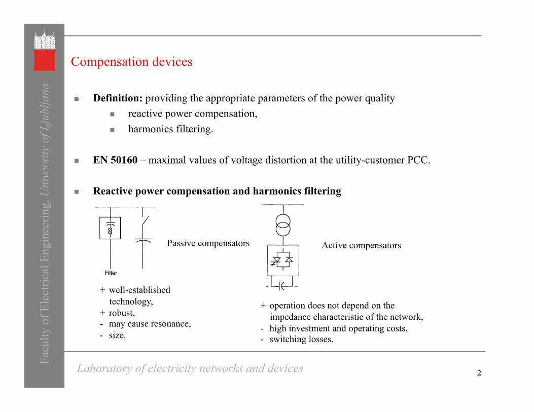
Compensation devices
Definition: providing the appropriate parameters of the power quality reactive power compensation, harmonics filtering.
EN 50160 – maximal values of voltage distortion at the utility-customer PCC.
Reactive power compensation and harmonics filtering
2
Active compensators Passive compensators
+ well-established technology,
+ robust, - may cause resonance, - size.
+ operation does not depend on the impedance characteristic of the network,
- high investment and operating costs, - switching losses.
Laboratory of electricity networks and devices Facu
lty o
f Ele
ctric
al E
ngin
eerin
g, U
nive
rsity
of L
jubl
jana

3
Filter topology
Hybrid active power filters combination of passive (elements RLC) and active part (VSC), passive part – reactive power compensation, active part – improving operational characteristics of the PP
Most common topological structures
Series hybrid filter Parallel hybrid filter
Facu
lty o
f Ele
ctric
al E
ngin
eerin
g, U
nive
rsity
of L
jubl
jana
Laboratory of electricity networks and devices

4
Simulated network description Fa
culty
of E
lect
rical
Eng
inee
ring,
Uni
vers
ity o
f Lju
blja
na
Laboratory of electricity networks and devices
Stiff network 3750 MVA Tr I 110/ 35 kV, 20 MVA, 10,82 % Tr II 35/0,676 kV, 3,25 MVA, 7,41 % Tr III 35/0,675 kV, 3,5 MVA, 6,62 % DCM I 2,5 MW, 690 V, 350/450 min-1 DCM II 2,15 MW, 690 V, 750 min-1 Other load 6,1 MW, 0,96 MVAr
Passive LC compensator QPF 5,4 MVAr LPF 11,8 mH CPF 13,81 µF fr-p 395 Hz, 1,6 %
Fig. Passive Compensator Parameters
Fig. Industrial Network Parameters
Fig. Simplified diagram of a real industrial network

5
Resonance problem Fa
culty
of E
lect
rical
Eng
inee
ring,
Uni
vers
ity o
f Lju
blja
na
Laboratory of electricity networks and devices
Fig. Calculated impedance-frequency characteristics of the network with and without passive filter; a)
series impedance, b) parallel impedance
Passive filter 5th 7 th 11 th 13 th THD
VF 8.77 0.21 0.09 0.1 8.78 IS 31.01 0.51 0.14 0.16 31.03 IF 72.20 6.63 1.01 0.83 72.51
Tab. Harmonic content
Fig. Simulated waveforms

6
Hybrid filter – topology and control algorithm Fa
culty
of E
lect
rical
Eng
inee
ring,
Uni
vers
ity o
f Lju
blja
na
Laboratory of electricity networks and devices
Used topology
o three-phase, two-level, voltage-source converter (VSC) connected in series with the passive filter capacitance and inductance
o the voltage drop on the capacitor reduces the VSC voltage ratings
o no coupling transformer
Control algorithm
Fig. Control block diagram of the active filter.
Fig. Basic circuit of the shunt-connected HAPF.
Control law:
o current controlled voltage source
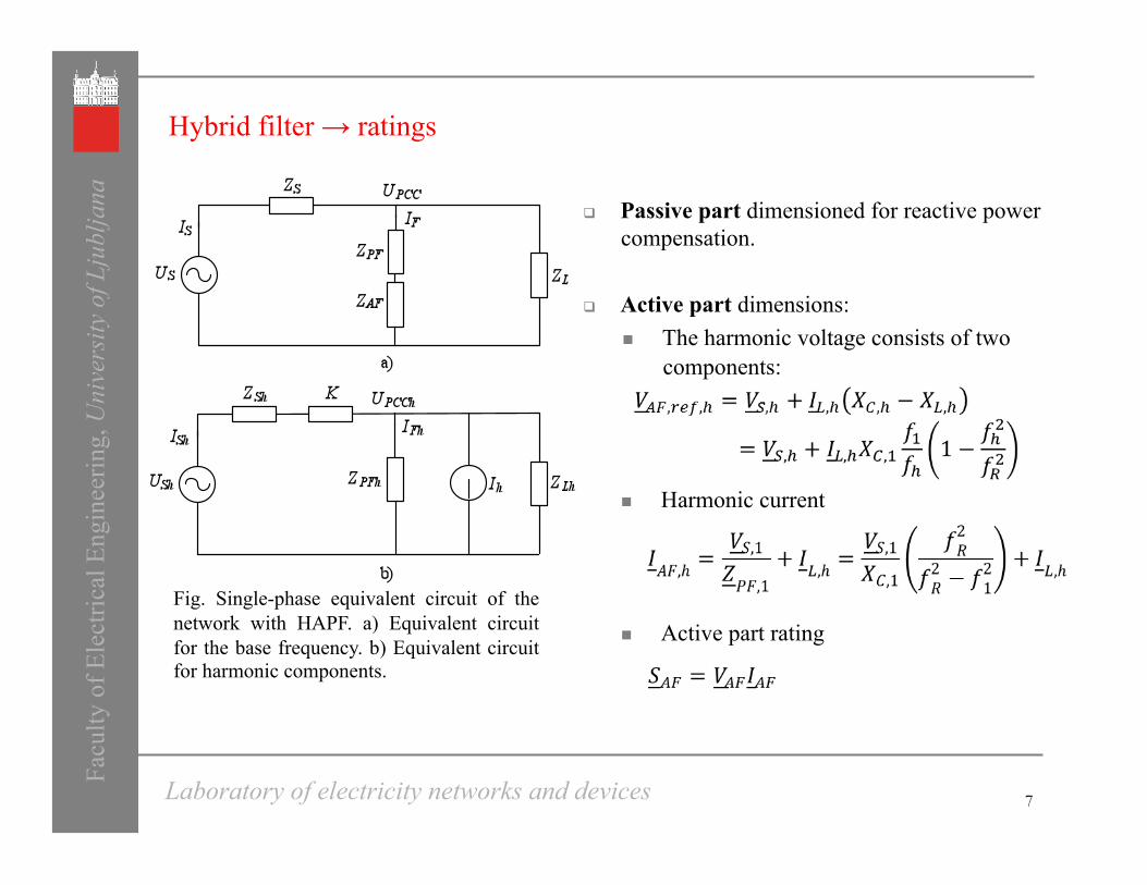
Passive part dimensioned for reactive power compensation.
Active part dimensions: The harmonic voltage consists of two
components:
Harmonic current
Active part rating
7
Hybrid filter → ratings
Facu
lty o
f Ele
ctric
al E
ngin
eerin
g, U
nive
rsity
of L
jubl
jana
Laboratory of electricity networks and devices
Fig. Single-phase equivalent circuit of the network with HAPF. a) Equivalent circuit for the base frequency. b) Equivalent circuit for harmonic components.
8
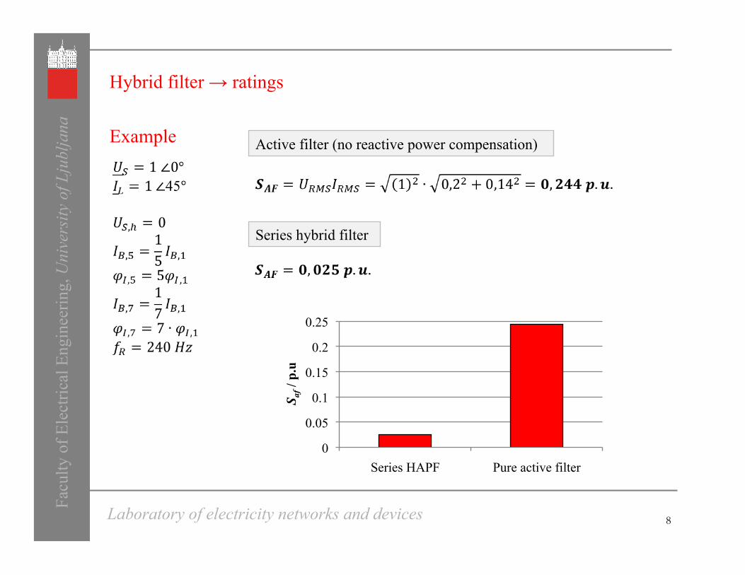
Active filter (no reactive power compensation)
Series hybrid filter
Hybrid filter → ratings
Example
Facu
lty o
f Ele
ctric
al E
ngin
eerin
g, U
nive
rsity
of L
jubl
jana
Laboratory of electricity networks and devices
0
0.05
0.1
0.15
0.2
0.25
Series HAPF Pure active filter
S af /
p.u
9
Frequency response characteristics Fa
culty
of E
lect
rical
Eng
inee
ring,
Uni
vers
ity o
f Lju
blja
na
Laboratory of electricity networks and devices
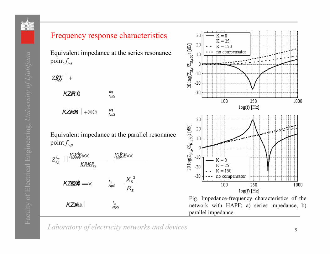
Equivalent impedance at the parallel resonance point fr-p
Equivalent impedance at the series resonance point fr-s
Fig. Impedance-frequency characteristics of the network with HAPF; a) series impedance, b) parallel impedance.

10
Simulation results Fa
culty
of E
lect
rical
Eng
inee
ring,
Uni
vers
ity o
f Lju
blja
na
Laboratory of electricity networks and devices
Fig. Simulated waveforms

Facu
lty o
f Ele
ctric
al E
ngin
eerin
g, U
nive
rsity
of L
jubl
jana
Laboratory of electricity networks and devices
Conclusion
The presented HAPF is composed of a small-rating VSC connected in series with a shunt single‑tuned passive filter.
For the connection to the network no transformer is needed.
Since the rated power of the active filter is relatively low, the HAPF represents a viable solution to reactive-power compensation and harmonic filtering.
The cost comparison between the hybrid, pure passive and stand-alone active filter is excluded from this paper, although it is mandatory as a proof of cost efficiency for the proposed solution.

Thank you for your attention!
Facu
lty o
f Ele
ctric
al E
ngin
eerin
g, U
nive
rsity
of L
jubl
jana
Laboratory of electricity networks and devices