Hybrid Active Filter Based on SVPWM for Power Conditioning ... · Conditioning using...
22
International Journal of Electronic and Electrical Engineering. ISSN 0974-2174 Volume 5, Number 2 (2012), pp. 113-133 © International Research Publication House http://www.irphouse.com Hybrid Active Filter Based on SVPWM for Power Conditioning using Matlab/Simulink Toolbox Environments 1 Naresh Kumar and 2 Prabhat Kumar 1 Faculty Member, 2 M.Tech. Student Arya College of Engg. & I.T., India E-mail: [email protected] Abstract In this paper presents control method for hybrid active filter using space vector pulse width modulation (SVPWM). In the proposed control method, the Active Power Filter (APF) reference voltage vector is generated instead of the reference current, and the desired APF output voltage is generated by SVPWM. A MATLAB code is developed to generate the SVPWM switching pulses fed to the two-level inverter topology. The entire power system block set model of the proposed scheme has been developed in MATLAB environment. The developed control algorithm is simple. The APF based on the proposed method can eliminate harmonics, compensate reactive power and balance load asymmetry. Simulation results show the feasibility of the APF with the proposed control method. Index Terms: SVPWM, Active Filter, Power Conditioning, Passive Filter Introduction The growing use of non-linear and time-varying loads has led to distortion of voltage and current waveforms and increased reactive power demand in ac mains. Harmonic distortion is known to be source of several problems, such as increased power losses, excessive heating in rotating machinery, significant interference with communication circuits, flicker and audible noise, incorrect operation of sensitive loads [1-2]. Passive filters are traditional method to eliminate harmonics, but with recent developments in power semiconductor switches and converters, coupled with developments in control techniques and analog and digital implementations, active filters are becoming an effective and commercially viable alternative to passive filters. They offer the
Transcript of Hybrid Active Filter Based on SVPWM for Power Conditioning ... · Conditioning using...

International Journal of Electronic and Electrical Engineering. ISSN 0974-2174 Volume 5, Number 2 (2012), pp. 113-133 © International Research Publication House http://www.irphouse.com
Hybrid Active Filter Based on SVPWM for Power Conditioning using Matlab/Simulink Toolbox
Environments
1Naresh Kumar and 2Prabhat Kumar
1Faculty Member, 2M.Tech. Student Arya College of Engg. & I.T., India
E-mail: [email protected]
Abstract
In this paper presents control method for hybrid active filter using space vector pulse width modulation (SVPWM). In the proposed control method, the Active Power Filter (APF) reference voltage vector is generated instead of the reference current, and the desired APF output voltage is generated by SVPWM. A MATLAB code is developed to generate the SVPWM switching pulses fed to the two-level inverter topology. The entire power system block set model of the proposed scheme has been developed in MATLAB environment. The developed control algorithm is simple. The APF based on the proposed method can eliminate harmonics, compensate reactive power and balance load asymmetry. Simulation results show the feasibility of the APF with the proposed control method. Index Terms: SVPWM, Active Filter, Power Conditioning, Passive Filter
Introduction The growing use of non-linear and time-varying loads has led to distortion of voltage and current waveforms and increased reactive power demand in ac mains. Harmonic distortion is known to be source of several problems, such as increased power losses, excessive heating in rotating machinery, significant interference with communication circuits, flicker and audible noise, incorrect operation of sensitive loads [1-2]. Passive filters are traditional method to eliminate harmonics, but with recent developments in power semiconductor switches and converters, coupled with developments in control techniques and analog and digital implementations, active filters are becoming an effective and commercially viable alternative to passive filters. They offer the

114 Naresh Kumar and Prabhat Kumar
following advantages: able to cover a wide range of harmonic frequencies; do not contribute resonant frequencies to the network; harmonic attenuation is network impedance dependent [3-4]. Among the various topologies the shunt active power filter based on voltage source inverter (VSI) is the most common one because of its efficiency. The performance of active power filters depends on the adoptive control approaches. There are two major parts of an active power filter controller. The first is that determines the reference current of APF and maintains a stable DC bus voltage. Various current detection methods, such as instantaneous reactive power theory [5], synchronous reference frame method [6], supplying current regulation [7] and etc., are presented. The commonness of these methods is the request for generating reference current of APF, either with the load current or the mains current. The second is that controls the VSI to inject the compensating current into AC mains. Similarly, various current control methods such as hysteresis [8], triangular wave control [9], deadbeat control [10] and etc., are presented. The commonness of these methods is to control VSI with the difference between real current and reference current. An alternative control method for shunt active power filters is proposed in this paper. The proposed method differs from previously discussed approaches in the following ways: a) To generate APF reference voltage vector instead of reference current; b) to generate desired APF output voltage by space vector modulation based on generated reference voltage at step a). Therefore, the proposed method is simple and easy to carry out by DSP. In this literature discussed the basic principle of this method in detail and proved its validity by simulation and experimental results. Mathematical Modelling of SVPWM Technique with APF This literature is briefly discusses the theory and operation of Space Vector Pulse Width Modulation (SVPWM) explains the implementation of SVPWM for the two level inverter topology. Philosophy of SVPWM Technique SVPWM technique was originally developed as a vector approach to pulse width modulation for three-phase inverters. The SVPWM method is frequently used in vector controlled applications. In vector controlled applications this technique is used for reference voltage generation when current control is exercised. It is a more sophisticated, advanced, computation intensive technique for generating sine wave that provides a higher voltage with lower total harmonic distortion and is possibly the best among all the pulse width modulation techniques. It confines space vectors to be applied according to the region where the output voltage vector is located. Because of its superior performance characteristics, it is been finding wide spread applications in recent years. The main aim of any modulation technique is to obtain variable output voltage having a maximum fundamental component with minimum harmonics. Many PWM techniques have been developed for letting the inverters to posses various desired output characteristics to achieve the wide linear modulation range, less switching losses, lower harmonic distortion. The SVPWM technique is more popular than conventional technique because of its excellent features.

Hybrid Active Filter Based on SVPWM for Power Conditioning 115
• More efficient use of DC supply voltage. • 15% more output voltage then conventional modulation. • Lower Total Harmonic distortion (THD). • Prevent un-necessary switching hence less commutation losses.
Principle of SVPWM Firstly model of a three-phase inverter is presented on the basis of space vector representation. The three-phase VSI is reproduced in Fig.2.1. ,1S to ,6S are the six power switches that shape the output, which are controlled by the switching variables
,a ,a ,b , ,,b c and ,c When an upper transistor is switched on, i.e., the corresponding ,a , ,,b , or ,c is0 . Therefore, the on and off states of the upper switches ,1S ,3S ,5S
can be used to determine the output voltage.
Figure 2.1: Power Circuit of a three-phase VSI The relationship between the switching variable vector a[ b c t] and line-to-line voltage vector [ ,abV ,bcV caV ] is given by (3.1) in the following:
⎥⎥⎥
⎦
⎤
⎢⎢⎢
⎣
⎡
⎥⎥⎥
⎦
⎤
⎢⎢⎢
⎣
⎡
−−
−=
⎥⎥⎥
⎦
⎤
⎢⎢⎢
⎣
⎡
c
b
a
V
V
V
V
dc
ca
bc
ab
101110
011 (2.1)
Also, the relationship between the switching variable vector a[ b c t] and the phase voltage vector [ ,abV ,bcV caV ]t can be expressed below.

116
⎢⎢⎢
⎣
⎡
−−−
−=
⎥⎥⎥
⎦
⎤
⎢⎢⎢
⎣
⎡V
V
V
Vdc
cn
bn
an
112112
3
As illustrated in Fig.patterns for the three uppedevices are opposite to ththe upper power transistothe eight switching vectorline-to-line voltages in tershows the eight inverter vo
Figure 2.2
Naresh Kumar and P
⎥⎥⎥
⎦
⎤
⎢⎢⎢
⎣
⎡
⎥⎥⎥
⎦
⎤−−
c
b
a
211
2.1, there are eight possible combinations er power switches. The on and off states of the upper one and so are easily determined on
ors are determined. According to equations rs, output line to neutral voltage (phase voltarms of DC-link dcV , are given in Fig.2.2 andoltage vectors ( 0V to 7V ).
2: Eight inverter voltages vectors (V0 to V7)
Prabhat Kumar
(2.2)
of on and off he lower power
nce the states of (2.1) and (2.2),
age), and output d Table 2.1 and

Hybrid Active Filter Based on SVPWM for Power Conditioning 117
Table 2.1: Switching vectors, phase voltages and output line to line voltages
Voltage vectors
Switching vectors Line to neutral voltage Line to line voltage a b c Van Vbn Vcn Vab Vbc Vca
Vo 0 0 0 0 0 0 0 0 0 V1 1 0 0 2/3 -1/3 -1/3 1 0 -1 V2 1 1 0 1/3 1/3 -2/3 0 1 -1 V3 0 1 0 -1/3 2/3 -1/3 -1 1 0 V4 0 1 1 -2/3 1/3 1/3 -1 0 1 V5 0 0 1 -1/3 -1/3 2/3 0 -1 1 V6 1 0 1 1/3 -2/3 1/3 1 -1 0 V7 1 1 1 0 0 0 0 0 0
SVPWM refers to a special switching sequence of the upper power switches of a three-phase power inverter. It has been shown to generate less harmonic distortion in the output voltages and/or currents applied to the phases of a power system and to provide more efficient use of supply voltage compared with other modulation technique. To implement SVPWM, the voltage equations in the abc reference frame can be transformed into the stationary qd − reference frame that consists of the horizontal (d) and vertical (q) axes as depicted in Fig.2.3.
Figure 2.3: The relationship of abc reference frame and stationary d-q reference frame From this figure, the relation between these two reference frames is given as
0dqf sk= abcf (2.3)
118 Naresh Kumar and Prabhat Kumar
Where, sK =⎥⎥⎥
⎦
⎤
⎢⎢⎢
⎣
⎡−−−
21212123230
21211
32 ,
fdq0 = [ 0fff qd ]T, =abcf [ cba fffT] ,
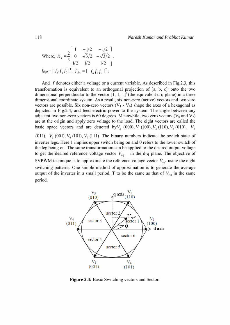
And f denotes either a voltage or a current variable. As described in Fig.2.3, this transformation is equivalent to an orthogonal projection of [a, b, c]t onto the two dimensional perpendicular to the vector [1, 1, 1]t (the equivalent d-q plane) in a three dimensional coordinate system. As a result, six non-zero (active) vectors and two zero vectors are possible. Six non-zero vectors (V1 - V6) shape the axes of a hexagonal as depicted in Fig.2.4, and feed electric power to the system. The angle between any adjacent two non-zero vectors is 60 degrees. Meanwhile, two zero vectors (V0 and V7) are at the origin and apply zero voltage to the load. The eight vectors are called the basic space vectors and are denoted by
0V ),000( 1V ),100( 2V ),110( 3V ),010( 4V
),011( 5V ),001( 6V ),101( 7V )111( The binary numbers indicate the switch state of inverter legs. Here 1 implies upper switch being on and 0 refers to the lower switch of the leg being on. The same transformation can be applied to the desired output voltage to get the desired reference voltage vector refV in the d-q plane. The objective of SVPWM technique is to approximate the reference voltage vector refV using the eight switching patterns. One simple method of approximation is to generate the average output of the inverter in a small period, T to be the same as that of refV in the same period.
Figure 2.4: Basic Switching vectors and Sectors

Hybrid Active Filter Based on SVPWM for Power Conditioning 119
Therefore, space vector PWM can be implemented by the following steps Step 1: Determination of ,dV ,qV refV an angle(α) Step 2: Determination of time duration T1, T2, T0 Step 3: Determination of the switching time of each switch (S1 to S6) Step 1: Determination of ,dV ,qV refV and angle (α)
60cos60cos ⋅−⋅−= cnbnand VVVV
= cnbnan VVV21
21
−−
30cos30cos0 ⋅−⋅+= cnbnq VVV
= cnbnan VVV23
23
−+
⎥⎥⎥
⎦
⎤
⎢⎢⎢
⎣
⎡
⎥⎥⎥⎥
⎦
⎤
⎢⎢⎢⎢
⎣
⎡
−
−−=⎥
⎦
⎤⎢⎣
⎡∴
cn
bn
an
q
d
V
V
V
V
V
23
230
21
211
32
22
qdref VVV +=∴
ftt
V
V
d
q πωα 2tan 1 ==⎟⎟⎠
⎞⎜⎜⎝
⎛=∴ − ,
where f =fundamental frequency
Figure 2.5: Voltage Space Vector and its components in (d, q)

120 Naresh Kumar and Prabhat Kumar
Step 2: Determination of time duration T1, T2, T0 From Fig.2.6, the switching time duration can be calculated as follows: Switching time duration at Sector 1
(Where, 0 ≤ α ≤ 60°)
( )⎟⎟⎟⎟
⎠
⎞
⎜⎜⎜⎜
⎝
⎛
==+−=∴
dc
ref
zzz
V
Vaand
fTwhereTTTT
32
1210
Figure 2.6: Reference vector as a combination of adjacent vectors at sector 1 Block Diagram of Control System The main section of the APF shown in Fig.2.7 is a forced-commutated VSI connected
∫ ∫ ∫∫+
+
++=1 21
1 210021
0
T TT
T
T
TT
T
ref
zz
VdtVdtVV
)..( 2211 VTVTVT refz +=⋅∴
( )( )⎥⎥⎦
⎤
⎢⎢⎣
⎡⋅⋅⋅+⎥
⎦
⎤⎢⎣
⎡⋅⋅=⎥
⎦
⎤⎢⎣
⎡⋅⋅⇒
3sin3cos
32
01
.32
sincos
21 π
π
αα
dcdcrefz VTVTVT
( )( )3sin3sin
1 παπ −
⋅⋅=∴ aTT z
( )( )3sin
sin2 π
α⋅⋅=∴ aTT z

Hybrid Active Filter Based
to dc capacitor. Considerinis usually very low, it canthree-phase balanced as sh
( )( )( )+=
−==
32sin32sin
sin
πωπω
ϖ
tVv
tVv
tVv
ssc
ssb
ssa
Where sV is the supp It is known that theexpressed as two-phase reis given by
112 23 30
2
d
sq
VV
V
⎡ −⎢⎡ ⎤⎢= =⎢ ⎥⎢⎣ ⎦⎢⎣
It is possible to write e
( sbsas avavV ++= 10
32
Figure 2.7: C
d on SVPWM for Power Conditioning
ng that the distortion of the voltage in public n be assumed that the supply voltage is idealhown below:
)) ⎪
⎭
⎪⎬
⎫
ply voltage amplitude? e three-phase voltages [ ,saV ,sbV scV ] in a
epresentation in qd − frame by Clark’s transf
123
2
sa
sb
sc
V
V
V
⎤ ⎡ ⎤− ⎥ ⎢ ⎥⎥ ⎢ ⎥⎥ ⎢ ⎥− ⎣ ⎦⎥⎦
equation (2.5) more compactly as
) sssqsdsc VjVVav θ∠=+=+ 2
Configuration of a Hybrid APF using SVPWM
121
power network l sinusoidal and
(2.4)
−a −b c can be formation and it
(2.5)
M

122
Whereπ
32
jea = , so b
stationary reference framamplitude of the voltages, As shown in Fig. 2.7, tthe main circuit and usesmaintain the dc bus voltequivalent circuit of the sy Compensation Principle
Figure 2.8: Equivalent cAPF In the Fig.2.8, 1faV andof the inverter, respective
,saV in parallel via a link
forced to be free of harharmonic current emitted f It is known from Fig.2the voltages of the ac susteady state
1 1
f
f
fsCdt
IdLV ∫+⋅=
Where sV is the supplfundamental voltage of Avector. The APF is joine
Naresh Kumar and P
alanced three-phase set of voltages is reprme by a space vector of constant magnitud
and rotating with angular speed fπω 2= . the shunt APF takes a three-phase voltage so capacitor as the energy storage element onage dcV constant. Fig.2.7 shows the per-ph
ystem described in Fig.2.8.
ircuit of a simple power system together w
d fahV denote the output fundamental and harely. These voltage sources are connected to ak inductor fL and capacitor fC .The supply
rmonics by appropriate voltages from thefrom the load is then automatically compensa2.8, that only fundamental component is takeupply and the APF exist the following rela
11 ff VdtI∫ +
ly voltage, 1fI is the fundamental current of AAPF, and above variables are expressed in ed into the network through the inductor
Prabhat Kumar
resented in the e, equal to the
ource inverter as n the dc side to hase (Phase A)
with the Hybrid
rmonic voltages a supply source y current ,sai is
e APF and the ated. en into account, ationship in the
(2.6)
APF, 1fV is the form of space
fL and fC the

Hybrid Active Filter Based on SVPWM for Power Conditioning 123
function of these is to filter higher harmonics nearly switching frequency in the current and to link two ac voltage sources of the inverter and the network. So the required inductance and capacitance can just adopt a small value. Then the total reactance caused by inductor and capacitor for the frequency of 50Hz, and the fundamental voltages across the link inductors and capacitors are also very small, especially compared with the mains voltages. Thus the effect of the voltage of the link inductor and capacitor is neglected. So the following simplified voltage balanced equation can be obtained from equation (2.6).
1fs VV = (2.7) The control object of APF is to make the supply current sinusoidal and in phase with the supply voltage. Thus the nonlinear load and the active power filter equals to a pure resistance load Rs, and the supply voltage and the supply current satisfy the following equation:
sss IRV ⋅= (2.8)
Where ( ) issqsdscsbsas IjIIaiaiaiI θ∠=+=++= 210
32 . Then the relationship
between Is and the supply voltage amplitude Vs is
sss IRV = (2.9) Substituting (2.8), (2.9) into (2.7) results in
s
s
sf I
I
VV ⋅=1 (2.10)
Equation (2.10) describes the relationship between the output fundamental voltage of APF, the supply voltage and the supply current, which ensure that the APF operate normally. However, for making the APF normally achieving the required effect, the dc bus voltage dcV has to be high enough and stable. In the steady state, the power supplied from the supply must be equal to the real power demanded by the load, and no real power passes through the power converter for a lossless APF system. Hence, the average voltage of dc capacitor can be maintained at a constant value. If a power imbalance, such as the transient caused by load change, occurs, the dc capacitor must supply the power difference between the supply and the load, the average voltage of the dc capacitor is reduced. At this moment, the magnitude of the supply current must be enlarged to increase the real power delivered by the supply. On the contrary, the average voltage of the dc capacitor rises, and the supply current must be decreased. Therefore, the average voltage of the dc capacitor can reflect the real power flow information. In order to maintain the dc bus voltage as constant, the detected dc bus voltage is compared with a setting voltage. The compared results are fed to a PI controller, and amplitude control of the supply current si can be obtained by output of
PI controller

124 Naresh Kumar and Prabhat Kumar
Figure 2.9: Control block diagram of proposed algorithm
The fig.2.9 shows the block diagram of active filter controller implemented for reducing the harmonics with hybrid active filter system. In each switching cycle, the controller samples the supply currents ,sai sci and the supply current sci is calculated with the equation of - (isa+isc), as the summation of three supply current is equal to zero. These three-phase supply currents are measured and transformed into synchronous reference frame (d-q axis). The fundamental component of the supply current is transformed into dc quantities in the (d-q) axis and the supply current amplitude si generated by the PI controller with dcV and refV , the reference value of
the dc bus voltage. The obtained d-q axis components generate voltage command signal. By using Fourier magnitude block, voltage magnitude and angle is calculated from the obtained signal. These values are fed to the developed code and compared with the repeating sequence. Then the time durations ,1T ,2T and 0T ,the on-time of 1V ,
,2V and 0V are calculated as already explained in literature. The generated switching actions are applied to the APF and power balancing of the filter takes place. Simulation and Results The developed control method for three-phase hybrid APF is simulated in MATLAB/Simulink. Firstly, the three-phase supply currents are sensed and transformed into synchronous reference frame (d-q) axis. The fundamental component of the supply current is transformed into dc quantities in the (d-q) axis and the supply current amplitude Is generated by the PI controller. The obtained d-q axis components generate voltage command signal. By using Fourier magnitude block, voltage magnitude and angle is calculated from the obtained signal. These values are fed to the developed code and generated switching actions are applied to the hybrid APF. Thus, power balancing of the filter takes place. Further, the performance with different type of loads is presented.

Hybrid Active Filter Based on SVPWM for Power Conditioning 125
The complete simulation model of APF with different type of loads is shown in Fig.2.12 and Fig.2.20 For an input supply voltage of 230V (rms) and switching frequency of 5 kHz, the simulation results before and after power balancing are shown.
Table 3.1: Parameter values
System parameters Values of parameters Supply system 220 ,rmsV 50 ,zH three phase supply Balanced linear load ,28.6501 Ω+= jZ Unbalanced linear load ,70.151001 Ω+= jZ a ,56.23751 Ω+= jZ b
,10.471501 Ω+= jZ c Non-linear load with resistance Ω= 500RAPF
mHL
fCVVfC
f
frefdc
25,70,900,450
=
=== μμ
Linear load Case 1: Balance RL load condition without APF
Figure 2.10: Simulation model of three phase balance RL-load condition without APF.

126 Naresh Kumar and Prabhat Kumar
Figure (a): Phase-A load current harmonic spectrum
phase-A Input source current harmonic spectrum
Figure (b): Phase-A source Current Harmonic Spectrum
Figure 2.11: Harmonic Spectrum of Linear Balance Load without APF Case2: SVPWM Technique for Linear balance RL load condition with APF
Figure 2.12: SVPWM Technique for linear balance RL-load condition with APF.

Hybrid Active Filter Based on SVPWM for Power Conditioning 127
Figure (a): Output Load current harmonic spectrum
Figure (b): Input source current harmonic spectrum
Figure 2.13: Harmonic spectrum of SVPWM Technique for linear balance RL-load condition with APF Case 3: For linear unbalance RL load condition without APF
Figure 2.14: Simulink model of three phase unbalance RL-load condition without APF.

128 Naresh Kumar and Prabhat Kumar
Figure (a): Output load current harmonic spectrum
Figure (b): Input source current harmonic spectrum.
Figure 2.15: Harmonic spectrum of three phase unbalance RL-load condition without APF Case 4: SVPWM Technique for Linear unbalances RL load condition with APF
Figure 2.16: Simulink model of SVPWM Technique for linear unbalance RL-load condition with APF.
Hybrid Active Filter Based on SVPWM for Power Conditioning 129
Figure (a): Output load current harmonic spectrum.
Figure (b): Input source current harmonic spectrum
Figure 2.17: Harmonic spectrum of SVPWM Technique for linear unbalance RL-load condition with APF. Nonlinear load Case 1: for Nonlinear R load condition without APF
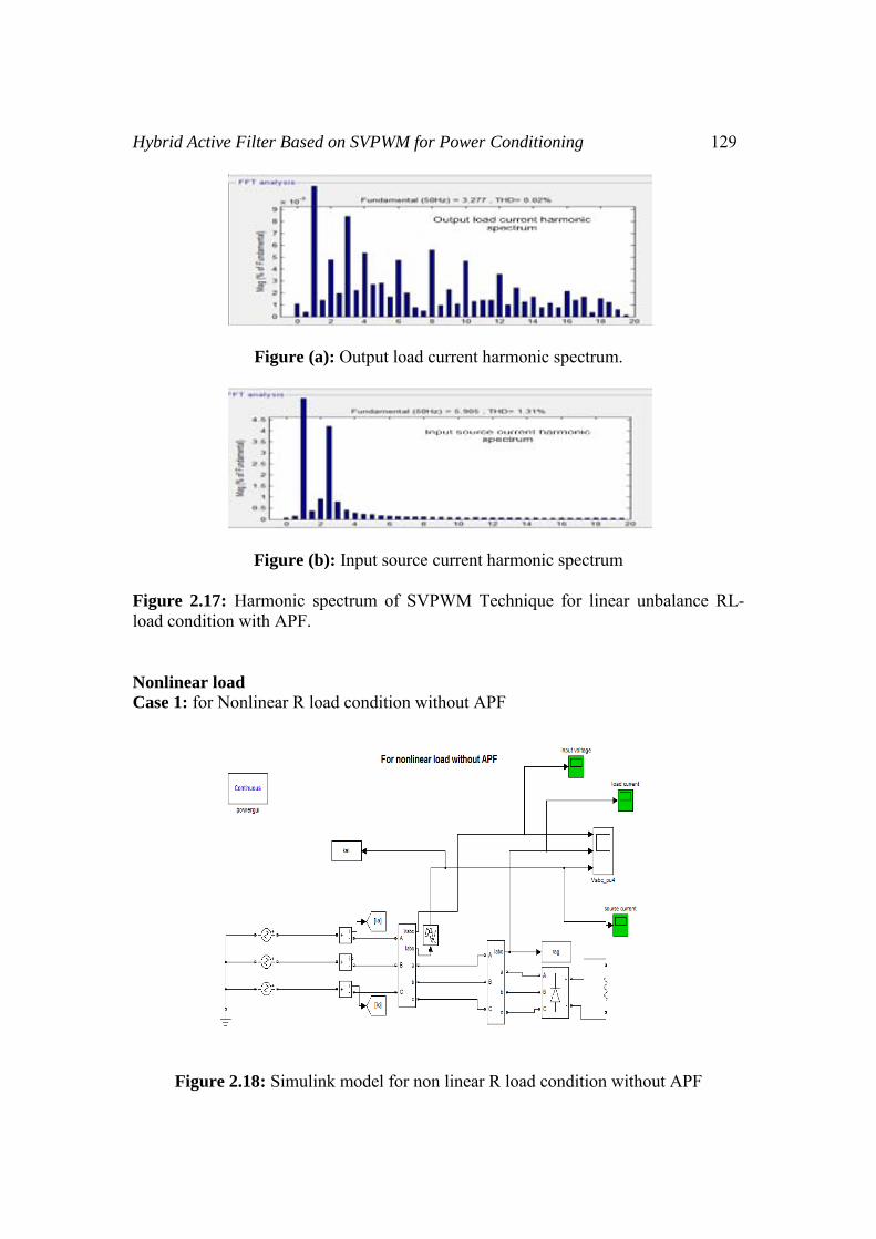
Figure 2.18: Simulink model for non linear R load condition without APF

130 Naresh Kumar and Prabhat Kumar
Figure (a): Output load current harmonic spectrum
Figure (b): Input source current harmonic spectrum
Figure 2.19: Harmonic spectrum of non-linear load without APF Case 2: SVPWM Technique for Nonlinear R load condition with APF
Figure 2.20: Simulink model of SVPWM Technique for Nonlinear R load condition with APF

Hybrid Active Filter Based on SVPWM for Power Conditioning 131
Figure (a): Output load current harmonic spectrum.
Figure (b): Input source current harmonic spectrum
Figure 2.21: Harmonic spectrum of SPWM Technique for Nonlinear R load condition with APF Result Analysis
Table: 3.2
Types of load
Without APF SVPWM Technique with APF
THD Load Side
THD Source side
THD Load Side
THD Source side
Linear Balance RL load 0.00% 0.00% 0.02% 1.21% Linear Unbalance RL load 0.00% 0.00% 0.01% 1.31% Nonlinear Rectifier with R load 30.28% 30.2% 30.28% 5.47%
From table3.2 shows the simulation of harmonic spectrum of linear three phase balance load .fig.2.11 (a) is the harmonic spectrum of the current before compensation on the load side. The load current total harmonic distortion (THD) is 0.00% whiles the supply current THD is 0.00%. It should be noted that no harmonic generated in linear three phase balance system. But when the APF is used the harmonic generate at the source side the value of supply current THD is 1.21% when SVPWM Technique used. And the value of supply current THD is 1.21% when SVPWM Technique used. From table3.2 show the simulation of harmonic spectrum of linear three phase

132 Naresh Kumar and Prabhat Kumar
unbalance load .fig.2.12 (a) is the harmonic spectrum of the current before compensation on the load side. The loads current total harmonic distortion (THD) is 0.00% while the supply current THD is 0.00%. It should be noted that no harmonic generated in linear three phase unbalance system. But when the APF is used, the harmonic generate at the source side, the value of supply current THD is 1.31% when SVPWM Technique used. From Table3.2 shows the simulation of harmonic spectrum of APF with SVPWM Technique used for non linear load used. When the non-linear is a three-phase diode bridge rectifier with resistance load. Fig.2.19 (a) is the harmonic spectrum of the current before compensation on the load side. The harmonic spectrum of the load current shows that magnitude of the 5th, 7th, 11th and 13th harmonics is very large. The harmonic spectrum of the source current shows that magnitude of the 5th, 7th, 11th and 13th harmonics are evidently reduced after compensation. The load current Total Harmonic Distortion (THD) is 30.28%, while the supply current THD is 5.47%.when SVPWM Technique used this is shown by fig.2.21. Conclusion The active power filter controller has become the most important technique for reduction of current harmonics in electric power distribution system. In this thesis a model for three-phase active power filter for balanced non-linear load is made and simulated using MATLAB/Simulink software package for the reduction harmonics in source current. the conclusions of the thesis such as: • During this paper work the performance of the hybrid active power filter is
analyzed using SVPWM technique for minimizing harmonics, and improving the power factor in the power system.
• The performance of the hybrid active power filter is verified with the simulation results. Form the results; it clearly indicates that, the current ripple is less by using SVPWM.
• In case of non linear load the THD response of the source current before compensation is 30.28%
• The THD of the source current after compensation is 5.47% by using SVPWM technique.
References
[1] Singh.B, Al-Haddad.K, Chandra.A, “Review of active filters for power quality improvement”, IEEE Trans. Ind. Electron., (46), 5, Oct, 1999, pp. 960-971.
[2] El-Habrouk. M, Darwish. M. K, Mehta. P, “Active power filters—A review,” Proc. IEE—Elect. Power Applicat. vol. 147, no. 5, Sept. 2000, pp. 403–413.
[3] Akagi, H., “New trends in active filters for power conditioning,” IEEE Trans. on Industry Applications, (32), 6, Nov-Dec, 1996, pp. 1312-1322.
[4] Peng Fangzheng, “Application issues of active power filters,” IEEE Industry Applications Magazine, v 4, n 5, Sep-Oct, 1998, pp. 21-30.

Hybrid Active Filter Based on SVPWM for Power Conditioning 133
[5] Akagi.H, Kanazawa.Y, and Nabae.A, “Instantaneous reactive power compensators comprising switching device without energy storage components,” IEEE Trans. on Industry Applications, (20), 3, 1984, pp. 625-630.
[6] S.Bhattacharya, D.M.Divan. “Synchronous frame based controller implementation for a hybrid series active filter system” IEEE- Industry Applications Society Annual Meeting, vol.3, 1995, pp. 2531-2540.
[7] Wu. J. C, “Simplified control method for the single phase active power filter,” Proc. IEE –Elect. Power Applicat. vol. 143, no. 3, 1996, pp.219- 224.
[8] David, M.E. and Round, S.D, “Fully digital hysteresis current controller for an active power filter”, International Journal of Electronics, (86), 10, Oct. 1999, pp. 1217-1232.
[9] Moran. L. A, Dixon. J. W, Wallace. R. R., “Three-phase active power filter operating with fixed switching frequency for reactive power and current harmonic compensation,” IEEE Tran. Ind. Electron. vol. 42, no. 4, Aug, 1995, pp. 402-408.
[10] Hamasaki, Shin-Ichi and Kawamura, Atsuo, “Improvement of current regulation of line-current-detection-type active filter based on deadbeat control,” IEEE Transactions on Industry Applications, v 39, n 2, 2003, pp. 536-541.