Hy-Power Labs,, Inc. - RigPix Database -...
9
\ *INSTRUCTION MANUAL* I44MH4 Bsnd A11 Mode Power AmpJ.ifler Model HL-IIOV Tokyo Hy-Power Labs,, Inc.
-
Upload
nguyenliem -
Category
Documents
-
view
217 -
download
2
Transcript of Hy-Power Labs,, Inc. - RigPix Database -...

iYF. :--rr3!ary
\
*INSTRUCTION MANUAL*
I44MH4 Bsnd A11 Mode Power AmpJ.ifler
Model HL-IIOV
Tokyo Hy-Power Labs,, Inc.

oSpuriousA low spurious signal emission(6Oda min. down)output low pass filter.
oAluminum heat sink with a combined case by ouris used. An excellent radiation effect as wellappeaxance 1s achieved.
.-+i:-Tt: --::e"qI
HL-llOV is a high pouúer linear amplifier designed for the I44MHzaII mode operation. It boasts of maximum output power of 120t'rl.Boosting low input even from hand-held(portable) transceiversto fuIl output pohrer due to input IeveI select switch.hlith a combination of built-in 1ow noise MQS FET receive pre-amp'HL-110V enables you to enjoy a more comfortable VHF DX QSO.
F EA TURE S
olnput pou,er level switch(2t{/f0|'l)Matchiirg with almost atl kinds of hand-he1d and'portable trans-ceivers-of It¡'J to ]trr| output, and mobile radio of 10t''l output.
oPower Level MeterYou can observe the output power; and check the power levelat aIt times. An accuraLe output'power can be read with a built-inprecision directional coupler of micro strip Iine.
oAll mode compatibility(SSB/FM)At ssB mode,'setting .the time constant of c0X(automatlc send-receive swii,ch) to ápprox. one second, a relay rarely chattersduring conversationr'ánd a smooth SSB transmission can be achieved.
oTerminal for Remote Send-Receive ControlA remóte eontrol terminal is accomodated at the rear pane1, whichenables a smooth and instant changeover especially on SSB modeand Chl mode when two leads are wiied to the remote control terminalof the transceiver.
with an effective
original designas a new, smart
SPECIFICATION
F requenc y
Mode
DC Power
Power Consumption
0utput pou,er
RF Input power
Input/Output lmPedance
Input/0utput conneetor
l44MHz band
FM . SSB . Ct¡l( AM )
DC13.8V(negative ground)
IgA (l,lax. )
I l0lrj ( Max . I20l¡'l )
2Wl1Ot'l selectable
504
M type
- r-:
I

Accessory circuit
Semlconductors
Acces sor I es
D imens i on
tJe ight
C0X(carrier operated T-R switch),Remote control jack,RX pre-amp, Power meter,Reverse DC power polarity protection
RF poh,er transistol x 3,Transistor x 5, Diode x L2,LEDx2
MobiIe mountlng bracket, M-M jumpercabIe, Remote control terminal plug(attached on rear panel), Fuse(20A),Instructlon manual
I72(w) x 60(H) x 263(D) mm
approx . 2.5 Kg
EXPLANATION OF FEATURES
*Fiont panel *Rear panel
@bcrs.svOpoumn @nxrup LEVEL
@oUTPUTPOI¡DR (FIG.I)
I . P0tr',ER ( DC Power switch )At off posltion, the amp 1s made t'THRUil state. The transmittingand receivlng signals will bypass the internal part of the HL-110V
2.OUTPUT POhIER (Power meter)Indicates transmitting output power, even at rrTHRUrr state t¡ans-mission.
,.MODE(FMISSB mode select)When changlng from TX(send) to RX(recelve) at "SSB'r, relaychange-over is made with some delay of approx. I second. Thischange is made lnstantly at rrFMrr.
4.RX AMP(RX receive pre-amp switch)At 0N position, the receivlng signal ls amplified. :
5.POWER LEVEL switchSelects either high or low output Ievel. At rrHIrr, a fu11 power isdelivered and at rrL0il' a half of the ful1 output.
2-
@oNAIR ORX

6.0N AIR pilot lampGreen lamp indicates the amp is transmitting o¡ on air.
7. RX pilot J.ampIt is_lighted when RX pre-amp is ready, even if DC power switch isoff. ( It can work independentty. )
S.INPUT LEVEL switchSeIect either I0!'l or 2W input leveI.
9.REMOTE(Remote control terminal)If the terminaL is conneeted to remote send-leceive control terminalof your transceiver, the transmitting and receiving switch canbe controlled remotely by the transceiver.
10. IN/TX(RF input)Connect the coaxial jumper cabte from ANT connector of transceiver.
II.OUT/ANT(RF output)Connect a coaxial jumper cable to antenna.
12.DC Power Ieads(11.8V)Bed for positive with fuse holder, BIack for negative.(Fuse holder is mounted on the pC board inside.)
CAUT I ON
Be earelul of following subjects which may become the cause of thetrciuble.
r.During transmission, the heat sink may reach a high temperature(approx. 50oc-80oc). Set the amp at a welL-ventiláted p1ace.Donrt put objects on top of the amp.
2.As the same way, don't operate the amp at praces where is exposedto the direct rays of the sun, or nearby a heater etc.f.Be sure to check the "Matching" or VSI¡üR of antenna before operation.
Measure rrSl¡úRrr value by uslng St¡rlR meter aecording to. FIG.2.I f St¡'lR val.ue is too high, adjust your antenna and the length ofthe cable to obtain a lower St¡'lR value.You had better obtain St¡,lR ]ess than l. i or hopef u1ly as Iow as l.
4.Choose a good mobile antenna which ulithstands a high pou,er, or. St''lR is degraded within a few minutes by heat after startingtransmission.It is necessary to withstand over 100!,J.
5.Don't try to drive over the rated 1eve1(2!,J or f 0t¡f ).Be sure to check not to select 2lnl input level for J-0trrl output trans-ceiver.
-3-

t
6.Be careful that DC power voltage ls kept no hlgher than Il.8V(I2-I4V). Some automobiles generate as hlgh as I5V. Althoughthls wlll not kill the amp immediately,lt ls most dangerous'1f such other bad conditlons oecur, as antenna mis-match orover drive, simultaneously
7.In case that AC to DC converter(stabtllzed power supply) ls usedat home station, some DC poh,er supplles produce abnormallyhigh output voltage due to high frequency RF lntruslon' whichwlll kill the RF power transistor of the amp.Use a DC power supply fully protected agalnst hlgh frequencylntrusion, and withstanding high current ¡rlhlle transmf tting.
INSTALLAT I ON
antenna
for remote
DCefP#"
toPowsup(Dc
Icontrol operatlon
-- coaxlalcable
PREPARATIONS BEFORE OPERATION
l.In case that the output power lstransceiver, set the input IeveI
.paneI and lock it again.
meter (FIG.2)or Directlonal
power meter
I to 2hJ type hand-held portábfesu¡itch to 'r2h,'t on the rear
knobbottom
(FrG.l)
\\_
J,screw
tr)
'power
lead
coaxlalcable
( soo)
_>_-._
%Lset theto the
,oá cl-------
oosen the screu, at the upside

2.Connect cables as required according to lIG.2 on page 4.J.Measure Sl'lR value of antenna. At f irst, turn the power switch of f ¡
and measure with the output Ievel of transceiver onIy.' ülhen St"lR i-s high, adJust the antenna height etc. to lower S|¡lR
. value to 1.¡ oi Iess.4.For a remote control operatlon from transceiver, remove ilREM0TErl
relay from rear panel at the base. According to FIG.), connectvinyl coated wires to "STAND-BY" terminal (remote control) atthe transcelver
oRear side view, the covef, of the plug belng renoved.
?t ,/3
}?Il4
NO DesiqnatloA Connectinq ooint at transceiver
I +DC Terminal or crrcuitry whichproduce DC+3-9V, on transmission
2 GND Ground at transceiver(GND)5 GND
4SHORT
-OPENTerminal or circuitry which is madeshort on transmission and open onreceotlon at the transceiver
(* Either of No. I or 2 availabte)
a
vinyl
3and2
insert to "REMOTE"terminal at the base
oConnectiona)Read the instruction manual of your transceiver,
to locate terminal pins whiclr correspond to mentionedtable "Connectino Point at transceiver".
b)In case that a terminal is not applied, search forcircuitry whlch comes to r'+DC" at tlre transceiver.
c)After a termfnal or circuitry are decided, cut twocords in suitable Iength, and solder as F'IG.5.
d)Solder two vinyl cords to either plns I and 2 orof the plug.
5.Fo¡ setting thewith an attachedand 8.
connect to t----1-F.+[ransceJ.ver
-L_____amp under the dash boardmoblle mountlng bracket
(FiG.5 )
panel of automobile, please refer to FIG.6,7
-5-

a)Construct the bracket.
fiber washer
b)Set the bracket to the dash paneI.
(FIG.6)
two points "rtn screrÍFrG'7)
not accessorles)
(FIG. S )
c)Set the devlce.
.ilf.O: uppgr both corner of the devfceErgnten the device spinnlng bolts onposltion on front anb rear-directlon.flnlshed.
OPERAT ION
r.Tu¡n the power switch on, and red ramp on front paner is righted.2'At receivino state., signars to and from antenna bypass theinternal pait of the d;;i;;. In that ease, you can hear recervedslgnal frbm the transcetvér.3.By turning.!h9 transcelver to.,,transmitrr the device is madeto rrtransmitting,power amptiiicaIioñ;-itátJ,' and hlgh powersignal is emlttád'rrom án[eñna. At the "árá'trme, green ramp(0N ArR) on'rront páñer-ii-righ,ted and iñ¿icates that the ainpis transmlttlng or on tne aii.4.Select "MODEI switch to operate mode.5.In case the recelyllg-signals.are weak, nolsy and hard tounderstand, turn "RX-AMp¡í i"it"t' on. -vóu'óáñ'r,"".
signalselearly with a Low noise.
lnto the braeket,both sldes at the'sultableAnd setting wil1 be
board
Put together(screws are
- 6-

TROUBLE SHOOTING (not troubte)
Symp t oms Cause T re atmen tIn spite of turningthe power swltch oifat mobile operatlon,the black lead of DCpower becomes hot.
You are connectinopower leads conveiselyto polarity of battery.
Connect power leads tothe battery at riqhtposition alain.
At transmittino.lnternal relay'íschattering.
l.The Input,uOutputconnectors are connect-ed on reverse side.
2.The voltage of the DCpgwer supply drops byRF signal intrusion.
l.Set a connector at theright position again.
2.To cure this, solder someof 0.1, 0.01, I00¡rFcapacitors in paralleland connect them to + and- terminal-s of DC powersupply.(It is not always effici-ent to get rid of thetrouble ¡vith this method.
Heat sink becomeshot remarkably.
Mis-matching of antenna. Lower SWR value of antenna.(nefer to T'CAUTI0N-1" onpage 3)
device doesn'tat transmittinq
receivlng.
Theworkand
Troubles of each coaxial.cables.
Check connection of coaxialcables, or if there istrSHORTn or ilOpEN" states.
Nominal output powercan not be achieved.
I.Input level switch atrear panel of trans-ceiver is set rrl0l^,r'.
2. Power level switch isset t'LOr' position.
S.Power voltage is veryLow.
I.Set tha input level to"2lnl". (Refer to TTPREPARA-
TION-I', on page 4)2.Set the pou,er level swÍtch
to ilHIrt.
l.a)Set the stabilized powersupply to the riqhtvoltage.
I
b)At automobile station. I
check the power leads' IcircuÍtry. I
-7-
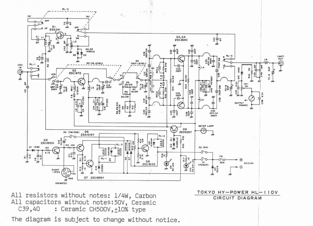
Q3rO42SC2630alll
3L o2,otI |(aOr2
0l uÍ¡!t 0i L€v¿ü
Ioao
t
IIoAo
a
!H
,-r"' foot
c3.a7?.crr300v
!¡. (Fulssst 0625ArOr5Y
All resistorsAIl capacitors
c39,4O :
The diagram is
withoutwithout
Ceramic
subjeet
notes z L/ AVl, Carbonnotes: 50V, Cerami-e
CH500V,¡IO% typeto change without notice.
=,r/o; t*'
TOKYO HY-POwER HLI I I oVCIRCUIT DIAGRAM


![One-loop E&M correlators of SQED in power-law …up by two-loop computations of the local scalar bi-linears, and the energy-momentum tensor, confirming its consistency [37, 38]. Recently,](https://static.fdocuments.us/doc/165x107/5fb7bea04ce4340f6c7bc2a3/one-loop-em-correlators-of-sqed-in-power-law-up-by-two-loop-computations-of.jpg)