HW#8 8_20 sol
13
HW #01 Due: 09/12/2012 ES 331 Name: Solution Set 1.2 1 of 13 hw01soln.docx Problem: Two solid cylindrical rods AB and BC are welded together at B and loaded as shown. Knowing that d 1 = 50 mm and d 2 = 30 mm, find the average normal stress at the midsection of (a) rod AB, (b) rod BC. Solution: The key to this problem is to take cuts through the rod assembly at the proper cross-sections when establishing the loads using Statics. Then it’s a simple matter to apply the stress definition to determine the requested average normal stresses. a.) Take a cut thru rod AB. The resultant upward reactionary force must balance the two downward forces: ( ) ( ) MPa m N m N kN kN kN P AB 65 . 35 10 65 . 35 10 50 4 10 70 70 30 40 2 6 2 3 3 = × = × × = ⇒ = + = - π σ b.) Take a cut thru rob BC. The resultant upward reactionary force simple balances the 30 kN downward force on the end of the rad: ( ) ( ) MPa m N m N BC 44 . 42 10 44 . 42 10 30 4 10 30 2 6 2 3 3 = × = × × = ⇒ - π σ Ans Ans
description
fdas yeah pho ni paper
Transcript of HW#8 8_20 sol

HW #01 Due: 09/12/2012
ES 331
Name:
Solution Set 1.2
1 of 13
hw01soln.docx
Problem: Two solid cylindrical rods AB and BC are welded together at B and loaded as shown. Knowing that d1 = 50 mm and d2 = 30 mm, find the average normal stress at the midsection of (a) rod AB, (b) rod BC.
Solution: The key to this problem is to take cuts through the rod assembly at the proper cross-sections when establishing the loads using Statics. Then it’s a simple matter to apply the stress definition to determine the requested average normal stresses. a.) Take a cut thru rod AB. The resultant upward reactionary force must balance
the two downward forces:
( )( )
MPam
N
m
N
kNkNkNP
AB 65.351065.35
10504
1070
703040
2
6
23
3
=×=
×
×=⇒
=+=
−πσ
b.) Take a cut thru rob BC. The resultant upward reactionary force simple
balances the 30 kN downward force on the end of the rad:
( )
( )MPa
mN
m
NBC 44.421044.42
10304
10302
6
23
3
=×=
×
×=⇒
−πσ
Ans
Ans
HW #01 Due: 09/12/2012
ES 331
Name:
Solution Set 1.7
2 of 13
hw01soln.docx
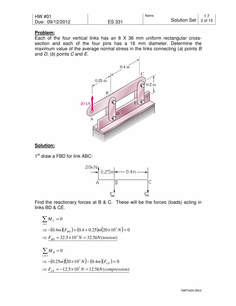
Problem:
Each of the four vertical links has an 8 X 36 mm uniform rectangular cross-section and each of the four pins has a 16 mm diameter. Determine the maximum value of the average normal stress in the links connecting (a) points B
and D, (b) points C and E.
Solution:
1st draw a FBD for link ABC:
Find the reactionary forces at B & C. These will be the forces (loads) acting in links BD & CE.
( )( ) ( ) ( ))(5.32105.32
0102025.04.04.0
0
3
3
tensionkNNF
NmFm
M
BD
BD
cw
C
=×=⇒
=×++−⇒
=∑+
( )( ) ( )( ))(5.12105.12
04.0102025.0
0
3
3
ncompressiokNNF
FmNm
M
CE
CE
ccw
B
=×−=⇒
=−×−⇒
=∑+

HW #01 Due: 09/12/2012
ES 331
Name:
Solution Set 1.7
3 of 13
hw01soln.docx
Note that the “links” at BD & CE are actually double links. Assume that they were machined to tight tolerances and that they carry the load equally. This means that each link is subject to ½ the load (or we could look at it as a single link with twice the cross-sectional area). Use the split load approach. For the link at BD:
eff
BD
BDA
P=σ
As noted, the load will be ½ the calculated reactionary force:
( ) kNkNPBD 25.165.322
1==
We need to consider the minimum area that supports this load. Because the link is in tension, we need to subtract the pin hole from the cross-sectional area (only the ‘legs’ surrounding the pin are available to counteract the load).
( )( ) 263310160101636108 mmmAeff
−−− ×=×−×=
( )( ) ( )tensionMPa
mN
m
NBD 6.101106.101
10160
1025.162
6
26
3
=×=×
×=⇒
−σ
For the link at CE:
eff
CE
CEA
P=σ
As noted, the load will be ½ the calculated reactionary force:
( ) kNkNPCE 25.65.122
1==
This link is in compression. Therefore, the effective area to support the load is the entire cross-sectional area of the link.
( )( ) 2633102881036108 mmmAeff
−−− ×=××=
( )( ) ( )ncompressioMPa
mN
m
NCE 7.211070.21
10288
1025.62
6
26
3
=×=×
×=⇒
−σ
Ans (a)
Ans (b)

HW #01 Due: 09/12/2012
ES 331
Name:
Solution Set 1.11
4 of 13
hw01soln.docx
Problem:
The frame shown consists of four wooden members, ABC, DEF, BE, and CF. Knowing that each member has a 2 X 4 in. rectangular cross section and that each pin has a ½ in. diameter, determine the maximum value of the average normal stress (a) in member BE, (b) in member CF.
Solution:
1st use the entire frame as the FBD:
( ) ( )( )lbfD
inlbfDin
M
x
x
ccw
A
0.900
0304548040
0
=⇒
=+−
=∑+
Next, consider the bottom link, DEF, as a FBD:
The reactionary force @ D must be parallel to the forces @ E & F:
( ) lbflbfDD xy 12009003
4
3
4===⇒
Next, sum moments:

HW #01 Due: 09/12/2012
ES 331
Name:
Solution Set 1.11
5 of 13
hw01soln.docx
( )( ) ( )
lbfF
inFinlbf
M
CF
CF
ccw
E
750
0305
4151200
0
=⇒
=+−
=∑+
( )( ) ( )
lbfF
inFinlbf
M
BE
BE
ccw
F
2250
0305
430151200
0
−=⇒
=−+−
=∑+
Finally, determine the normal stress in each link. Note that link CF will be in tension and BE will be in compression. This will affect the effective cross-sectional area calculation.
A
P=σ
For Link BE: The link is in compression, so the effective cross-section is:
( )( )
( )eCompressivin
lbf
in
lbf
A
F
inininA
BE22
2
3.2818
2250
824
===⇒
==
σ
For Link CF: The link is in tension. Therefore, we must subtract the hole:
( ) ( )
( )Tensilein
lbf
in
lbf
A
F
inininA
CF22
2
1.1077
750
725.4
===⇒
=−=
σ
Ans
Ans

HW #01 Due: 09/12/2012
ES 331
Name:
Solution Set 1.14
6 of 13
hw01soln.docx
Problem: A couple M of magnitude 1500 N ⋅ m is applied to the crank of an engine. For the position shown, determine (a) the force P required to hold the engine system in equilibrium, (b) the average normal stress in the connecting rod BC, which has a 450 mm2 uniform cross section.
Solution:
1st consider a FBD consisting of the crank, connecting rod, and piston:
( )kNNH
mHmN
Mccw
A
357.510357.5
028.01500
0
3 =×=⇒
=+⋅−⇒
=∑+
Next, consider the piston as the FBD. Noting that the connecting rod is a 2-force member (it’s pin connected), we know the direction of the force it must exert. Draw the force triangle to aid is analysis.
( ) ( ) 8.2086020022 =+=l
( )kNP
kN
P
H
P86.17
357.560
200=⇒==
kNFkN
F
H
FBC
BCBC 64.18357.560
8.208=⇒==
Ans

HW #01 Due: 09/12/2012
ES 331
Name:
Solution Set 1.14
7 of 13
hw01soln.docx
Note that the connecting rod, BC, is in compression.
( )( )eCompressivMPa
mN
mm
mmm
N
A
P43.411043.41
10450
1064.182
6
2
3
2
3
=×=
×==σ
Ans
HW #01 Due: 09/12/2012
ES 331
Name:
Solution Set 1.16
8 of 13
hw01soln.docx
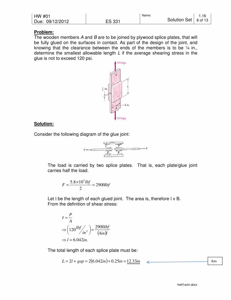
Problem:
The wooden members A and B are to be joined by plywood splice plates, that will be fully glued on the surfaces in contact. As part of the design of the joint, and knowing that the clearance between the ends of the members is to be ¼ in., determine the smallest allowable length L if the average shearing stress in the glue is not to exceed 120 psi.
Solution:
Consider the following diagram of the glue joint:
The load is carried by two splice plates. That is, each plate/glue joint carries half the load.
lbflbf
F 29002
108.53
=×
=
Let l be the length of each glued joint. The area is, therefore l x B. From the definition of shear stress:
( )
.042.6
4
2900120 2
inl
lin
lbf
in
lbf
A
P
=⇒
=
⇒
=τ
The total length of each splice plate must be:
( ) ininingaplL 33.1225.0042.622 =+=+= Ans
HW #01 Due: 09/12/2012
ES 331
Name:
Solution Set 1.21
9 of 13
hw01soln.docx
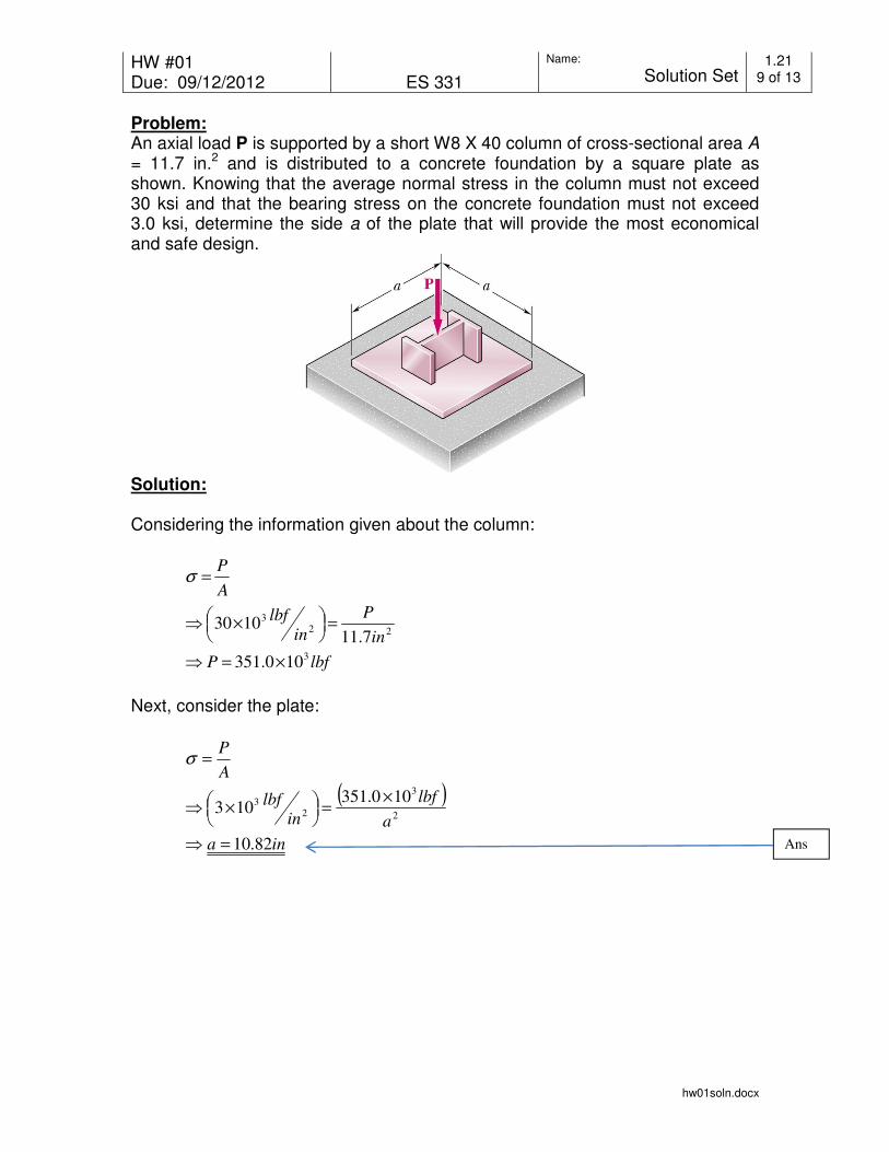
Problem:
An axial load P is supported by a short W8 X 40 column of cross-sectional area A
= 11.7 in.2 and is distributed to a concrete foundation by a square plate as shown. Knowing that the average normal stress in the column must not exceed 30 ksi and that the bearing stress on the concrete foundation must not exceed 3.0 ksi, determine the side a of the plate that will provide the most economical and safe design.
Solution:
Considering the information given about the column:
lbfP
in
P
in
lbf
A
P
3
22
3
100.351
7.111030
×=⇒
=
×⇒
=σ
Next, consider the plate:
( )
ina
a
lbf
inlbf
A
P
82.10
100.351103
2
3
2
3
=⇒
×=
×⇒
=σ
Ans
HW #01 Due: 09/12/2012
ES 331
Name:
Solution Set 1.26
10 of 13
hw01soln.docx
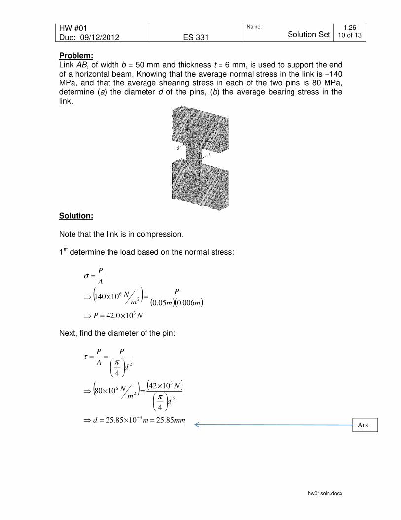
Problem:
Link AB, of width b = 50 mm and thickness t = 6 mm, is used to support the end of a horizontal beam. Knowing that the average normal stress in the link is −140 MPa, and that the average shearing stress in each of the two pins is 80 MPa, determine (a) the diameter d of the pins, (b) the average bearing stress in the link.
Solution:
Note that the link is in compression. 1st determine the load based on the normal stress:
( )( )( )
NP
mm
P
mN
A
P
3
2
6
100.42
006.005.010140
×=⇒
=×⇒
=σ
Next, find the diameter of the pin:
( ) ( )
mmmd
d
N
mN
d
P
A
P
85.251085.25
4
10421080
4
3
2
3
2
6
2
=×=⇒
×=×⇒
==
−
π
πτ
Ans
HW #01 Due: 09/12/2012
ES 331
Name:
Solution Set 1.26
11 of 13
hw01soln.docx
Finally, find the average bearing stress in the link noting that the member is in compression:
( )
( )( ) MPam
Nmm
N
td
Pb 7.270107.270
1085.25006.0
10422
6
3
3
=×=×
×==
−σ
Ans
HW #01 Due: 09/12/2012
ES 331
Name:
Solution Set 1.28
12 of 13
hw01soln.docx
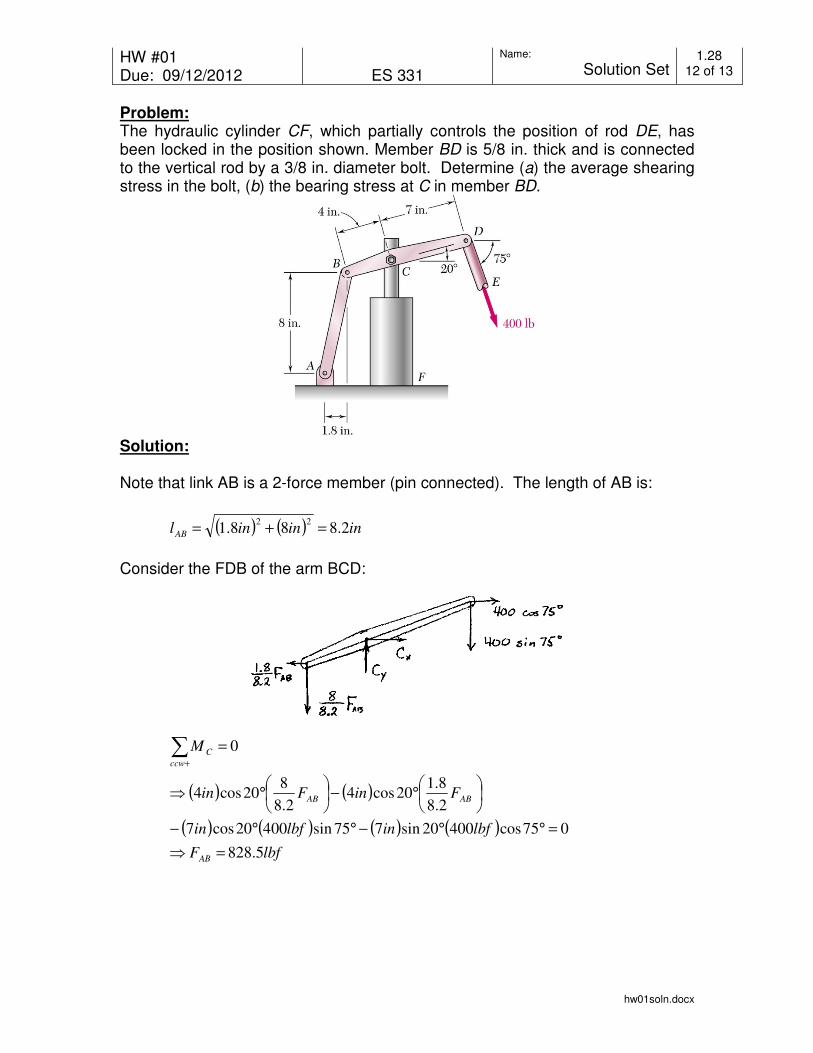
Problem:
The hydraulic cylinder CF, which partially controls the position of rod DE, has been locked in the position shown. Member BD is 5/8 in. thick and is connected to the vertical rod by a 3/8 in. diameter bolt. Determine (a) the average shearing stress in the bolt, (b) the bearing stress at C in member BD.
Solution:
Note that link AB is a 2-force member (pin connected). The length of AB is:
( ) ( ) inininlAB 2.888.122 =+=
Consider the FDB of the arm BCD:
( ) ( )
( ) ( ) ( ) ( )lbfF
lbfinlbfin
FinFin
M
AB
ABAB
ccw
C
5.828
075cos40020sin775sin40020cos7
2.8
8.120cos4
2.8
820cos4
0
=⇒
=°°−°°−
°−
°⇒
=∑+

HW #01 Due: 09/12/2012
ES 331
Name:
Solution Set 1.28
13 of 13
hw01soln.docx
( )
( ) ( )
lbfC
lbfClbf
lbfCF
F
x
c
cAB
x
34.78
075cos4005.8282.8
8.1
075cos4002.8
8.1
0
=⇒
=°++
−⇒
=°++
−⇒
=∑→+
( )
( ) ( )
lbfC
lbfClbf
lbfCF
F
y
y
yAB
y
1195
075sin4005.8282.8
8
075sin4002.8
8
0
=⇒
=°−+
−⇒
=°−+
−⇒
=∑↑+
( ) ( ) lbflbflbfC 1197119534.7822 =+=⇒
Now that we have the force @ C, we can find the requested stresses:
( )
ksiin
lbf
in
lbf
A
P84.101084.10
8
3
4
11972
3
2=×=
==
πτ
( )
ksiin
lbf
inin
lbf
td
Pb 107.510107.5
8
3
8
5
11972
3 =×=
==σ
Ans
Ans