HW TRAflSFER BY DIRECT FLAME COfHACT FIRE TESTS … · HW TRAflSFER BY DIRECT FLAME COfHACT FIRE...
55
0* to CO FINAL RF-PORT Subcontract No. HM 48-71-01 Report No. OE-122-FR HW TRAflSFER BY DIRECT FLAME COfHACT FIRE TESTS - PHASE I J. R. Welker C. M. Sliepcevich Prepared for National Academy of Sciences Committee on Hazardous Materials U.S. Coast Guard Cargo Containment Panel Washington, D. C. 20418 July 1971 ;rti ;&z*^ Os- j-.,. public leieosa» NATIONAL TECHNICAL . f^ P J INFORMATION SERVICE •-' L> v. icoqlicid /» 22151 ^Vn/ \P—(n-i -- by UNIVERSITY ENGINEERS NORMAN/ OKLAHOMA 73069 a.!..., i J FEB 9 197? - l \ iJIf/lTL^nn / INC. UL JC3L-_ v '^
Transcript of HW TRAflSFER BY DIRECT FLAME COfHACT FIRE TESTS … · HW TRAflSFER BY DIRECT FLAME COfHACT FIRE...
0*
to CO
FINAL RF-PORT
Subcontract No. HM 48-71-01
Report No. OE-122-FR
HW TRAflSFER BY DIRECT FLAME COfHACT FIRE TESTS - PHASE I
J. R. Welker
C. M. Sliepcevich
Prepared for
National Academy of Sciences
Committee on Hazardous Materials
U.S. Coast Guard Cargo Containment Panel
Washington, D. C. 20418
July 1971
■;rti ;&z*^ Os-
j-.,. public leieosa»
NATIONAL TECHNICAL . f^ P J INFORMATION SERVICE •-' L> v.
icoqlicid /» 22151 ^Vn/ \P—(n-i ■--
by
UNIVERSITY ENGINEERS
NORMAN/ OKLAHOMA 73069
a.!..., i
J FEB 9 197? -l\ iJIf/lTL^nn / INC. ULJC3L-_
v '^
JMCUSSmED Sr-runtv 4'tj--«.if«- ifs
OOCUMcHT COKTKOL DATA • H S. Ü fSmrwttm ctm*m't*fmtt*m of **♦!* KWr rm—f* tn*,0m*i *■* -««.^f •■• »t.t««« ■# M l.^n fh« o****** »*•••-••/ -« r' • .•i'f^'f.
university Engineers, Inc. Norman, Oklahoma
«.••C-l'OHI S(.CtJ*4l'« t l.*ii*t *(. A IIO^
Unclassified
J6, inou>-
13J ». •>tl'c»ST HILL
Heat Transfer by Direct Flame Contact - Fire Tests - Phase I
Technical July 1971 %. A|/1v*>ll|S} (r if *'n^<r«, eii^t-'ic t*-t:i*.i. i.**.t i.ttt**. j
J. R. Welker C. M. Sliepcevich
6- fViPC»- T D*Tt
July 1971 tv. IOI *l. MO- C »iCCS
50
I ib. wo. OF r.crs
I . 12 tM. CO:irN*CT O«* CH»«T no
Subcontract No. HM 48-71-01 : t. ^ROJecT NO.
723201
»J. OKIOINAIOB-» «COMr HUMUtKIM
ÜE-122-FR
ifti* report)
N/A 10. OISTR<f>UTION S.-ATEMtNT
Unlimited
11. Sut'OI.CMCN i ARY MC f «S
None
II. S^CMSONIoib UIUITARY ACTivirr
Division of Applied Technology U. S. Coast Guard, 400 Seventh Street, S.W Washington, D. C. 20590
AasVRi.CT '
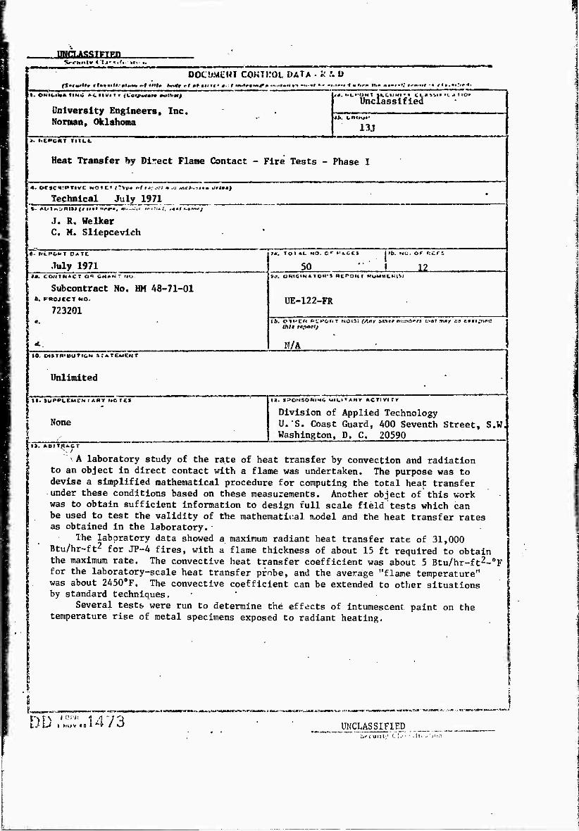
' A laboratory study of the rate of heat transfer by convection and radiation to an object in direct contact with a flame was undertaken. The purpose was to devise a simplified mathematical procedure for computing the total heat transfer under these conditions based on these measurements. Another object of this work was to obtain sufficient Information to design full scale field tests which can be used to test the validity of the raathematiral iu>del and the heat transfer rates as obtained in the laboratory.
The laboratory data showed a maximum radiant heat transfer rate of 31,000 Btu/hr-ft2 for JP-4 fires, with a flame thickness of about 15 ft required to obtain the maximum rate. The convective heat transfer coefficient was about 5 Btu/hr-ft2-0F for the laboratory-scale heat transfer probe, and the average "flame temperature" was about 2450oF. The convective coefficient can be extended to other situations by standard techniques.
Several tests were run to determine the effects of intumescent paint on the temperature rise of metal specimens exposed to radiant heating.
j >MCO'•Mafrtca-fMiutA.-ni*«nmtt.r. n'K
nn 'ly^'''■ "> d'!^ UNCLASSIFIED .ViUlll;' C 1." ' .ll.
UHCLASSIFT£D SCC'JJI'V C"irf'-'..fir.'»fi<>ft
14. KCv wonot
heat transfer fire tests heat flux heat measurement thermal radiation radlent heat transfer convective heat transfer flame temperature
fawaL'—ww—m—*
UNCLASSIFIED St'cunly Cla-isiflf a'i Mi
1
FINAL REPORT
Subcontract No. HM 48-71-01
Report No. UE-122-PR
HEAT TRANSFER BY DIRECT FUtf€ CONTACT FIRE TESTS - PHASE I
J. R. Welk-r
C. M. Sliepcevich
Prepared for
National Academy of Sciences
Committee on Hazardous Materials
U.S. Coast Guard Cargo Containment Panel
Washington, D. C. 20418
July 1971
by
UNIVERSITY ENGINEERS/ INC.
NORMAN, OKLAHOMA 73069
-UNIVERSITY ENOIMEERS. IMC

ABSTRACT
A laboratory study of the rate of heat transfer by
convection and radiation to an object in direct contact with a
flaue was undertaken. The purpose mis to devise a simplified
mathematical procedure for computing the total heat transfer under
these conditions based on these measurements. Another object of
this work was to obtain sufficient information to design full
scale field tests which can be used to test the validity of the
mathematical model and the heat transfer rates as obtained in the
laboratory.
The laboratory data showed a maximum radiant heat trans- 2
fer rate of 31,000 Btu/hr-ft for JP-4 fires, with a flame
thickness of about 15 ft required to obtain the maximum rate.
2 The convective heat transfer coefficient was about 5 Btu/hr-ft -0F
for the laboratory-scale heat transfer probe, and the average
"flame temperature" was about 2450oF. The convective coefficient
can be extended to other situations by standard techniques.
Several tests were run to determine the effects of in-
tvmescent paint on the temperature rise of metal specimens exposed
to radiant heating.
-UNIVERSITV ENGINEERS, INC

n
TABLE OF CONTENTS
Page
INTRODUCTION 2
HEAT TRANSFER MODELING 3
Heat Transfer to a Liquid-Filled Tank 3 Heat Transfer to a Gas-Filled Tank 5 Heat Transfer to an Uninsulated Object 7
LABORATORY HEAT TRANSFER DATA 10
Radiative Heat Transfer Experiments 10 Convective Heat Transfer Experiments 20 Discussion of Heat Transfer Data 29 Other Laboratory Data 35
TEST PLAN 46
REFERENCES 50
-UNIVERStT," ENGIMEERS. IMC

INTRODUCTION
This report presents the results of a laboratory study
on the heat transfer rate from fires by direct flame contact.
The work was undertaken to provide preliminary design informa
tion for several proposed large scale fire tests in which liquid
storage tanks of up to 10,000 gal capacity would be subjected to
direct flame contact heating tests. The ultimate goal is to be
able to predict the heating rate of the tank and its contents
for the design of vents to relieve the internal tank pressure
during fires and thereby prevent rupture of the tank with sub-
sequent loss of flammable or toxic contents.
The report first describes the simplified mathematical
analysis of heat transfer from a flame to an object in direct
contact with the flame. Specific examples are given for several
cases of possible interest. The results of laboratory data on
heat transfer from flames are then presented. It is shown how
these data may be extended to other fire conditions. Laboratory
tests on metal samples and samples coated with intumescent paints
are reported. Finally, a brief test plan for large scale fire
tests is presented.
-UNIVERSITY ENGINEERS, INC.

HEAT TRANSFER MODELING
Consider an object to be surrounded by fiza zvom a burning
hydrocarbon fuel. The object is heated by the flame by radiation
and convection. Each case of interest must be considered individu-
| ally in order to evaluate its response to heating by the fire, but
the fundamental information necessary to evaluate the heat transfer
behavior involves only consideration of flame radiation, convective
heat transfer, and the system properties. Three cases of interest I
will be considered here: heat transfer to a tank containing liquid,
heat transfer to the metal above the liquid surface, and heat trans-
fer to a metal object insulated on one side.
Heat Transfer to~a Liquid-filled Tank
The tank is assumed to be full or nearly full of liquid.
Since the metal wall of the tank will usually have a relatively
high thermal conductivity, its resistance to heat transfer can be
neglected. Likewise, the heat capacity of the metal wail will be
small compared to the heat capacity of the liquid inside the tank,
and it may also be neglected. The heat transfer equation may then
be written as
^r + qc = qt + % (1)
where q = radiant flux absorbed by the tank r
' q = convective flux to tank c
-UNIVERSITY EMC3INEERS. IMC.

4
q. = heat transfer rate through tank wall
q = radiant flux emitted by tank
The convective heat flux to the tank can be given by
qc = h(Tf - T) (2)
where h = convective heat transfer coefficient
T, = effective "flame temperature"
T = tank wall temperature
The heat transfer through the tank wall is quite rapid because
the internal wall is wetted by liquid. If the liquid contents
of the tank are assumed to be heated uniformly (or if a suitable
average temperature is used), the heat transfer through the tank
wall is just the heat absorbed by the liquid as its temperature
rises, and
qt = MC § (3)
In Equation 3
M = mass of liquid in the tank
C = heat capacity of liquid
t - time
and the tank wall temperature and the temperature of the liquid
in the tank are assumed to be equal.
The radiant flux emitted by the tank, q , is small in com-
parison to the other terms and can be neglected unless the tank
temperature rises beyond 5000F. Equation 1 can be then written as
-UMIVERSITV ENGrNEERS, INC.
MCp3l= % + h(Tf - T) (4)
and the temperature of the tank contents at any time can be
calculated if the initial temperature is known. Equation 4 applies
only as long as the tank contents remain below the liquid boiling
point and no significant evaporation takes place.
In practice, q . h, and Tf are taken as constants. Generally
speaking, the radiative flux will be greater than the convective
flux by at least a factor of two or three, and the boiling temperature
will limit the maximum value of T. Once boiling of the bulk liquid
begins, the boiloff rate can be found from
m AHv = qr + h{Tf - Tb) (5)
where m = mass evaporation rate due to boiling
AH = heat of vaporization of liquid
T. = liquid boiling temperature
The evaporation rate can be used to calculate the pressure rise in
the tank and subsequently to calculate the venting time and venting
rate for the tank.
Heat Transfer to a Gas-filled Tank
If a tank is full of gas when exposed to a fire, the tank
wall temperature will rise because the heat transfer rate to the gas
inside the tank is relatively slow. The heat transfer equation may
be written as
q+q=q. +a+q (6) ^r ^c ^t 'e Mg v '
•UINJIVERSITV ENGINEERS, INC.

6
where qt is now taken to be the heat transfer rate to the tank wall
and q is the cocvective heat flux to the gas in the tank. The con«
vective flwt frca the fire is
V h(Tf ' T) (7)
where T is the tack wall temperature. The emitted flux is
qe = eaT4 (8)
where e » average emittance at temperature T
a - Stepheui-Boltzaiann constant
(In reality, emission includes two terms, emission from the outer
surface of the tank and emission from the inner surface of the tank.
However, for a non-absorbing gas the inner surface receives the same
net radiative flux from its surroundings as it emits, thus canceling
the effect of the emitted flux on the interior. If the tank con-
tains an absorbing gas or liquid, adjustments must be made in the
heat transfer equation.)
The heat absorbed by the tank wall is
qt » PtCtx § (9)
where p. = density of tank wall
C. = heat capacity of tank wall
x = tank wall thickness
Heat transfer to the gas inside the tank is
qrt = h„ (T - T ) (10) g g g
-UNIVERSITY ENGINEERS, INC.
where h ■ convective heat transfer coefficient for inside 9
tank wall
T - gas temperature inside tank
For a transparent gas, the temperature rise rate will be relatively
slow, so T can be taken to be a constant.
Combining Equations 6 through 10 and rearranging the result
gives
PtCtx Ü = ^r + h(Tf ' T) " £aT4 " hg(T " V (11)
Equation 11 can be used for calculating the tank wall temperature
up to the time at which the tank wall begins to melt. The tank
wall will obviously fail at the melting point if it has not failed
previously.
Heat Transfer to an uninsulated object
The heat transfer rate to an uninsulated object inside a
fire can be used to predict the temperature rise of such an object.
Such calculations are useful in predicting the failure time of tank
supports, for example. The basic equation for heat transfer is
MsCsal=<3r + h(Tf -T) -"T4 (12>
where M is the mass of the object and C is its heat capacity
The object is assumed to have a high thermal conductivity, such as
for a metal.
The size and geometry of the object are important in
determining the range of temperature rise. For example, consider
three cases, a large flat plate, a long cylinder, and a sphere.
-UMIVERSITY ENGINEERS. INC.
8
For a flat plate, heat transfer through the edges of the plate can
be neglected. Then
xspsCs Ü ' 2qr + ^^f " T> " 2eaT4 <13>
where the flame is assumed to contact both sides of the plate.
The plate thickness is x and its density is p . If exposure is S 8
long enough and the object is not melted or consumed by the fire,
the steady state temperature can be calculated frc
qr + h(Tf - T) » eoT4 (14)
If the object is a long cylinder, heat transfer to the
cylinder through its ends may be neglected, and
dpsCa dT 4 —|-^ S = qr + h(Tf " T) " eaT <15>
where d is the diameter of the cylinder. Notice that in this case
the rate of temperature rise is inversely proportional to the diam-
eter of the object, assuming all other parameters to be constant.
For a sphere of diameter d the rate of temperature rise is
dpsCs dT 4 -r2- is <*r + h(Ts " T) " eöT (16)
where d is the diameter of the sphere. The rate of temperature rise
for the sphere is also inversely proportional to its diameter. The
rate of rise of a sphere is 1.5 times as rapid as for a cylinder
because the ratio of surface area to volume is 1.5 time as large.
-UMIVERSJTY EIMOINEERS. IMC.
The steady state temperature of both cylinders and spheres can be
calculated from Equation 14, just as for a flat plate.
Hone of the above equations account for melting of the
object during the heating process. If the metals have a constant
melting point, the fraction of metal melted can be calculated by
substituting
dT df psCs at Ä psAHf 3t (17)
in Equation 13, 15, or 16 when the temperature reaches the melting
point, providing the solid is contained as it melts. The temperature
is taken as the melting temperature, f is the fraction melted, and
ABf is the heat of fusion. If melting occurs over a temperature
range, as fouAd with some alloys, the temperature rise mast continue
to be calculated during melting. The substitution
Pscs at - pscs + (*E-tB) (18)
may be used to estimate the temperature. Equation 18 is based
on a linear estimate of the fraction of melting as a function of
temperature. The fraction melted may be calculated from
T - T f = B
T - T E D
(19)
where T is the temperature at which melting begins, and T is
the temperature at which melting is completed.
-UNIVERSITV EMGIMEERS, INC.
LABORATORY HEAT TRANSFER DATA
Most of the independent parameters appearing in the heat
transfer equations in the preceding section are properties of the
materials sobjected to the fire. Three of the paraneters are
properties of the fire, and the values of the parameters may de-
pend on the fuel being burned, the fire size, and the geometry
of the object receiving heat from the fire. These-paraneters are
the radiative flux , the convective heat transfer coefficient in
the fire, and the flame "temperature." A series of laboratory
measurements was made to determine the values of these parameters
for heat transfer calculations.
Two types of laboratory tests were run, one in which
radiant heat transfer from a fire was measured for various fire
thicknesses, and one in which the total heat transferrate was
measured for a probe completely surrounded by fire.
Radiative Heat -Transfer Experiments
Figure I is a schematic diagram of the experimental apparatus
used for measuring radiative heat transfer properties. An open
liquid-filled burner about 20 inches long and 2 inches-wide was
filled with JP-4. The fuel was maintained at a constant'level in
the burner by a liquid-sealed constant head siphon vrtiich led to a
fuel supply tank. The burner and radiometer were contained inside
a cabinet which was open beneath and above the burner. Fresh air
was drawn up through the cabinet, passing through a flow straightening
10
-UMIVERSITY ErviGtIMEERS. INC.

11
AIR FLOW
( I I ! }.
JP-4 FLAME
I - * I
i E m ¥ I
I I I I
I
FLAME CABINET
RADIOMETER
•BURNEK
SCREEN
HONEYCOMB
■SCREEN
Figure 1. Schematic Diagram of Laboratory Radiation Measuring Apparatus.
-UNIVERSITY EIMGIMEERS, INC.
12
section, then past the flame, and finally out the top of th* cabi-
net. Combustion products were exhausted through the top of the
cabinet along with the air being drawn through the cabinet. The
flame burned-uncontrolled above the burner except for restrictions
on the radiometer path length (L in Figure 1), which were'made in
order to determine the radiation properties. The'scare of turbu-
lence was smaller than that of the direct flame contact-experiments,
which, as will be shown later, influences the opacity of the flame.
There was no premising of air and fuel; all air entered the flame
zone by turbulent mixing and ultimately by diffusion.' As is char-
acteristic with diffusion flames, the flame path lengthtD decreased
slightly for a few inches above the burner, then increased farther
up the flame.
Radiometer measurements were made high enough up-into the
flame that the fuel and air were well mixed. Just above-the burner
surface, the flame had a fuel-rich zone which was visually trans-
parent. This zone was avoided during radiometer measurements. The
radiometer was designed for low net fluxes and was fitted*with a
water-cooled view restrictor to limit its viewinr-angler-■Both
radiometer and view restrictor could be purged with-an inert gas
during operation to prevent accumulation of smoke or soot. The
radiometer sensor was protected by a sapphire window to prevent
convective effects. The sapphire window transmits radiation from
the visible region to more than 6 microns in wavelength, so that
essentially all of the flame radiation energy reaches"the sensor.
The radiometer was calibrated with the view restrictor in place
using a blackbody radiation source.
"UNIVERSITV ENGIMEERS, IMC.
: I
4
13
Traditionally, radiant heat transfer from a flame has been
calculated using a modification of the Stephan-Boltzmann law,
qr = Fefo Tf4 (1 - e'KL) (20)
where q = radiant flux
Cf s emittance of the flame
a = Stephan-Boltzmann constant
T- = flame "temperature"
ic = flame opacity coefficient
L = flame thickness
F = view factor I
In practice. Equation 20 is applied by first measuring the radiant
flux from a fire and then calculating from that flux an "equivalent
blackbody temperature," The emittance is then assumed to be unity
and the equivalent blackbody temperature is used for heat transfer
predictions^ Alternatively, the flame "temperature" is measured
by an independent technique, such as an optical pyrometer or a
thermocouple, and the emittance is calculated from the measured
radiant flux and the temperature.
It is well known that the Stephan-Boltzmann law does not
apply to a flame because the flame emits radiation both in a con-
tinuum and in bands., The continuum radiation is attributed to hot
carbon particles and the major bands are attributed to emission
from hot H20 and CC^ molecules. Love (8) has proposed that the
flame be treated as an emitting, absorbing medium, with the basic
transport equation
-UMIVERSITY ENGIMEERS. IMC.
14
ar- = Jx - *xh {2r'
where I « monochromatic intensity
J, = monochromatic volumetric emission coefficient
ß. = monochromatic extinction coefficient
L « path length
Equation 21 is one-dimensional, and has the solution
J, -ß.L Ix « 5^. (1 - e
A ) (22) A
Further integration over the geometry of the particular problem
of interest and the wavelengths containing significant flame
radiant energy can be made if enough information on the values
of J< and ß. Ce.n be obtained.
unfortunately, measured values of J, and ß. are not avail-
able for the fuels of interest in this study. However, Equation 22
can be integrated over all applicable wavelengths and geometry to
obtain a simplified equation which can be used for predicting heat
transfer. The simplified form is
qr = FA(1 - e"bL) (23)
where A is the maximum emission from the fire and b is an extinction
coefficient. A comparison of Equations 20 and 23 shows that they
are equal if
b = K (24)
and A = eföTf (25)
-UMIVERSITY ENGINEERS, INC
15
Both A and b are related to Equation 22; A is an "average" value
of J /$ , integrated over all important wavelengths, and b is an A A
"average" value of 0, , again integrated over all wavelengths. The
view factor, F, is related to the geometry and converts intensity
to total flux.
The radiation measurements made with the narrow angle
radiometer were analyzed using Equation 23. The viewing angle of
the radiometer was narrow enough so that only the flame was viewed.
Measurements of the radiant flux from the fire were made for several
path lengths through JP-4 flames by decreasing the flame length.
Figure 2 shows the results. The data shown in Figure 2 were used
to calculate the maximum flux. A, and the extinction coefficient,
b, for the test fires. The results showed
A = 31,000 Btu/hr-ft2
b = 0.156 in"1
The value of b measured during the narrow angle radio-
meter tests is high. An optically thick fire, i.e., a fire which
would emit 99 percent of the maximum radiant flux, would be only
about 30 inches thick, a value significantly lower than that
accepted by most investigators. The reason for the abnormally high
value of b and the small optically thick fire is the small scale
of turbulence in the test fires. With a burner only 2 inches wide,
the size of individual flame zones is also small, but the number
of flame interfaces is relatively large. Since emission and extinc-
tion occur primarily at the flame interfaces (where fuel and air
are in the proper proportions for combustion), the extinction
coefficient becomes larger as the scale of turbulence becomes
smaller. Another way of explaining the large value of b due to
-UNIVERSITY ENGIMEERS, INC.

16
35.000
FLAME PATH LENGTH, INCHES
Figure 2. Radiant Flux for JP-4 Fires from a 2-Inch Wide Burner.
■UNIVERSITY ENGIMEERS. INC.

17
the smaller scale of turbulence is that the average concentration
of flame zones is higher for a smaller seals of turbulence.
Since the value for b measured for the 2-inch burner was
clearly not suitable for use in predicting heat transfer from
moderate fires with roughly circular or square bases, radiation
measurements were made on circular fires 12, 18, and 24 inches in
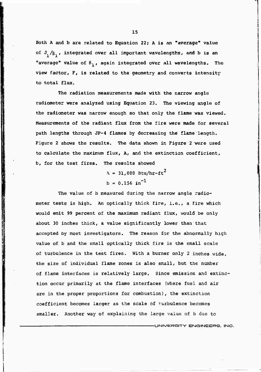
diameter. Figure 3 shows a schematic diagram of the circular
fire testing equipment, which was used in conjunction vith the
direct flame contact heat transfer experiments. A wide angle
radiometer was mounted outside the flame zone but near the flame
where the radiant flux was highest. The radiometer was water cooled
and purged with nitrogen to prevent smoke accumulation on the
sapphire window that covered the sensor. The view angle of the
radiometer was greater than 150 degrees, so the entire field of
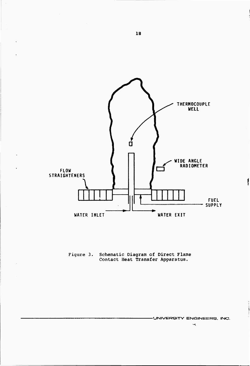
view was not always covered by the flame. Figure 4 is a photo-
graph of an 18-inch JP-4 fire.
Equation 23 was rearranged to
b = (-1/L) In (1 - qr/FA) (26)
in order to solve for the extinction coefficient for the circular
2 burner fires. The value of 31,000 Btu/hr-ft , as determined from
the narrow angle radiometer tests, was used for A, and view factors
were taken from the work of Rein et al. (11). The flame diameters
at the radiometer height varied from about 17 inches to about 32
inches, as measured from photographs of the flames»
-UNIVERSiTV EMGIMEERS. IMC
18
FLOW STRAIGHTENERS
THERMOCOUPLE WELL
WIDE ANGLE RADIOMETER
FUEL SUPPLY
WATER INLET WATER EXIT
Figure 3. Schematic Diagram of Direct Flame Contact Heat Transfer Apparatus.
■UMIVERSITY ENGINEERS. INC.
19
\^ ^ ^'
^ *vt
Figure 4. Photograph of an 18-Inch JP-4 Fire.
-UNIVERSITV ENGINEERS. INC.

20
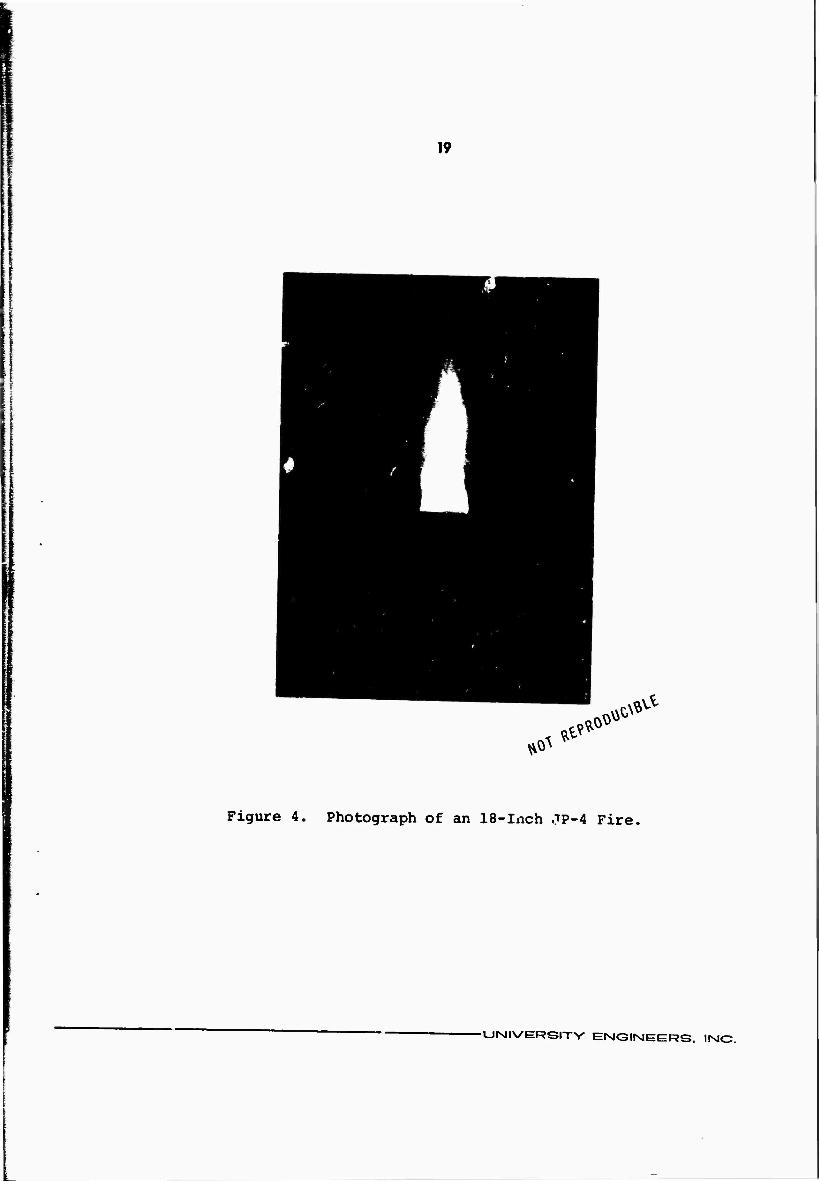
Figure 5 is a plot of the radiation data fron tiie circular
burner fires., plotted on semilogarithnic coordinates. Using the
maximum flux of 31,000 Btu/hr-ft found fro« the tests described
above, the average extinction coefficient was found to be 0.0186
inch" . A f?re which would emit 99 percent of the maximum flux
based on this value of b would have to be about 20 ft through the
flame zone. This value of b is within the range normally expected
for hydrocarbon fires.
Convective Heat Transfer Experin^nts
Nine expeximents were xur using a water-cooled heat
transfer probe. The probe was mounted at the center of a circular
pan as shown schematically in Figure 3. Pan diameters were 12,
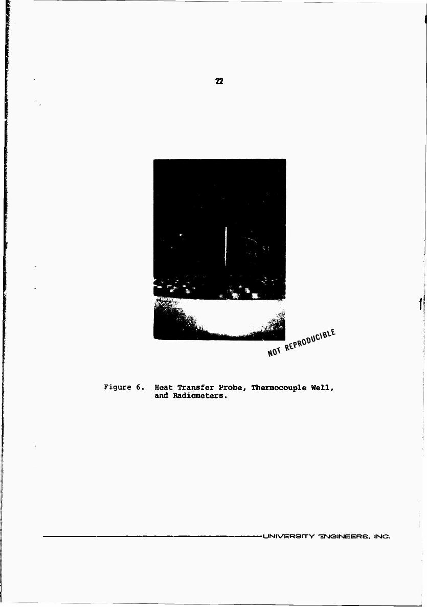
18, and 24 inches. Figure 6 shows the heat transfer'probe, the
thermocouple well for measuring the flame temperature, and the
radiometers for measuring the radiant flux outside the fire. The
flow straightening tubes surround the entire burner and test equip-
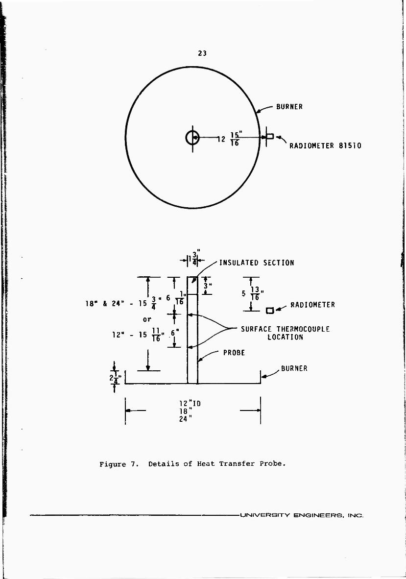
ment. Figure 7 gives the dimensions of the probe and shows the
location of the thermocouples on the outer wall of the probe.
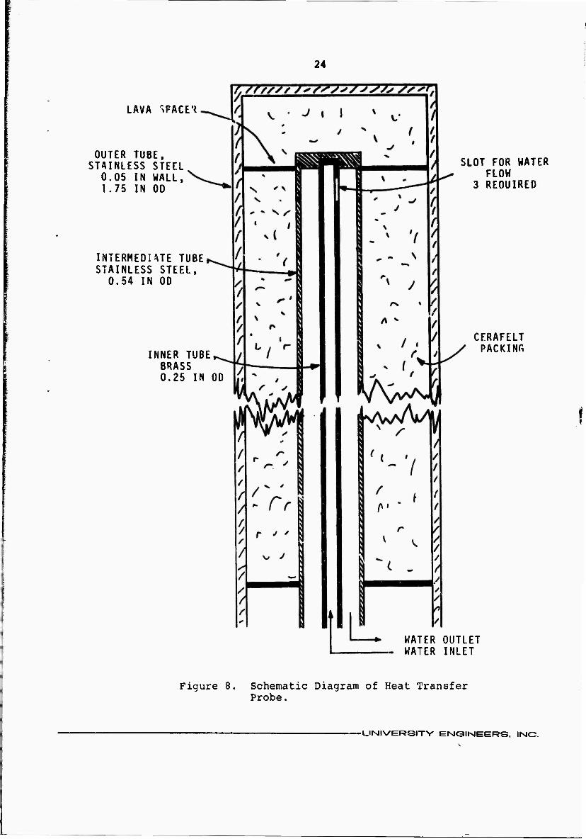
The probe was constructed of three concentric tubes, as
shown in Figure 8. Cooling water flowed up through the inner tube
and back down and out between the inner tube and the intermediate
tube. The space between the intermediate tube and the outer tube
was filled with insulation. The purpose of the insulation was to
decrease the heat transfer rate to the water and raise the tempera-
ture of the outer tube, which was in direct contact with the sur-
rounding fire. It was hoped that the higher temperature of the
-UNIVERSITV ENGINEERS. IMC.
21
^ <0
o
CO U UJ X M CJ 0 z IM
in 1-4
«M (0 • +> »- n X n ta »—< h UJ 0) X U-l
n o DC a cvi Ui «
1- ^ UJ t« s: o *J •—< 10 o 0) < X cc
in ■p i— 1- c
<
QC -0 UJ «D • h- K (0 UJ 0) z: rH M < (0 -H
o •-H C b p— o V4
UJ •P 1 ;S7 X cu < U hi
in
o • •
o 00
■
o o o
(Vd/^b - D
•n
o
»a-
o
0) u 3 CT
•H
-UNIVERSITY ENC3IMEERS. INC.
22
Figure 6. Heat Transfer Probe, Thermocouple Hell, and Radiometers.
-UNIVERSITY -HNQIMEEERS, IMC.
23
BURNER
RADIOMETER 81510
H'lK INSULATED SECTION
T 18" & 24" -
12"
O ' II 2f
T36.. or f
3" 1..—
"«-■£
i 12 ID 18" 24"
13.1
RADIOMETER
SURFACE THERMOCOUPLE LOCATION
PROBE
BURNER
Figure 7. Details of Heat Transfer Probe.
-UISIIVERSITV ENGIMEERS. INC.
I
24
LAVA ^PACE'^
OUTER TUBE. STAINLESS STEEL
0.05 IN WALL, 1.75 IN OD
INTERMEDim TUBE STAINLESS STEEL,
0.54 IN OD
INNER TUBE BRASS 0.25 IN OD
SLOT FOR WATER FLOW
3 REQUIRED
CFRAFELT PACKING
WATER OUTLET WATER INLET
Figure 8. Schematic Diagram of Heat Transfer Probe.
■UNIVERSITY ENGIMEERS. INC.

25
outer wall would aid in preventing carbon deposition on the probe
surface. However, even at the high temperatures at which the
outer shell operated, more than 1100oF, some carbon still collected
on the probe surface. The water flow rate was held constant during
a test, and the temperatures of the inlet water, the outlet water,
the nrobe wall, and the thermocouple well were monitored
continuously.
A heat balance on the active area of the probe was written
to determine the heat transfer rates. At steady state conditions,
qr + qc = %. + ^e (27)
where q is the heat flux absorbed by the water flowing through
the probe, i.e..
mC AT
^w = OLja (28) AP
In Equation 28 m = mass flow rate of water
C = specific heat of water w
T = temperature rise of the water flowing through
the probe
A = active surface area of the probe, based on
flame contact area
Since all the independent variables in Equation 28 are known, a
can be calculated directly.
The emitted energy, q , is calculated from the Stephan-
Boltzmann law,
■UNIVERSITY ENIGINIEtHRS. INC.

26
q = cy T 4 (29) e p
where T is the probe surface temperature. The emittance of the
probe surface has been assumed to be unity because the surface is
covered with a thin layer of carbon as soon as it is contacted by
the fire.
The radiant flux, q , is calculated from Equation 23 with
the view factor taken as unity because the entire probe is surrounded
by flame. The optical path length is obtained by taking the
average distance from the probe wall to the outer edge of the
flame. The flame dimensions are obtained from photographs taken
during the experiments. The values of A and b for the radiant
heat transfer calculations are those measured as described in the
previous section.
Once atq, and q have been obtained, q_ can be found
from Equation 27. The convective heat transfer rate involves
both the flame temperature and a convectiva heat transfer coeffi-
cient, i.e.,
qc = h(Tf - Tp) (30)
Since it is desired to determine the convective coefficient, the
flame temperature must be determined. The term uflame temperature"
is difficult to define because a flame is a reacting medium and is
not in equilibrium. Several techniques have been used in the past
to determine a "flame temperature," but the results vary widely,
especially for turbulent diffusion flames. For the purposes of
-UNIVERSIT-V ENGINEERS, INC.

27
heat transfer, the flame temperature is best determined from heat
transfer data. In the present experiments, the flatme temperature
was determined by a steady state heat balance on a small stainless
steel cylinder suspended in the flame near the heat tr?nsfer probe.
At steady state, the heat transfer equation for the cylinder is
qr + hc (Tf - Tc) = ca Tc4 (31)
where li is the convectivo heat transfer coefficient and T is the c c
cylinder temperature. Knudsen and Katz (6) give correlations for
estimating convective heat transfer coefficients, from which h was
2 estimated to be about 10 Btu/hr-ft -0F. The steady state cylinder
temperatures were measured during each of the experimental runs,
and the emittance was taken to be one. The radiant flux was
calculated in the same manner as for the larger heat transfer
probe. All the parameters in Equation 31 were then known except
for the flame temperature, which could be calculated.
Once the flame temperature had been calculated. Equation
27 could be used to calculate the average convective heat transfer
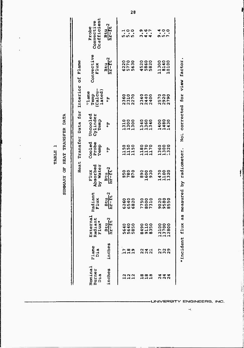
coefficient for the probe. Table 1 shows the results and summarizes
the data from the direct flame contact heat transfer measurements.
The convective heat transfer coefficient obtained from the heat 2
transfer data ranged from a minimum of 3.9 Btu/hr-ft -*F to a
2 maximum of 9.4 Btu/hr-ft -0F. The value of 9.4 appears a little
high. The average value of the convective coefficients, excluding
the single data point which appears questionable, is approximately
2 5 Btu/hr-ft -0F. The average "flame temperature" is calculated to
be about 2450oF.
-UNIVERSITY EISIGIMEERS, IMC,
28
+» 1 0) C
> 0) <N (|) -H-H 4J XI +J 0 srw rH O O a> vo r~ ^ o o 0 0 H 4J | • • • • • • • • • M ai «w 03 »4 m m m ro w a» m r^
&< >»w Ä ß fl) 0 o ÜU
0) > <N •
V •rl ■P o oo o o o o oo u +> X 3M oi r» n OJ VO tN 0^*0 0 Ü 3 4J 1 fM r>- vo m oo oo rO rH rH *i
H 4) H a M vo in m ^r in m rH 00 O o b > b J3 rH H id
Ö «M m O
! o U I ^ •H o 1 ^ >
■'-' gj ^tj ^ | ao 0) o o o o o o O O O u 0) 3 e ^ +J
r-t 3 «J (0 b VO rH r» *9 <f O p» n m 0
** o ro n (N tn rr ■& m a» p«- MH c (' EH U--« CM CM CN OJ <N CM «M CN CM H
0) ^ +>
< o •0 U Ü
* IH 0) 0) a) < H «d a O O O o o o o o o u Q td o c g b rH O O *f w O 00 ro u
4J O-H 0) 0 ro ci PO ro ro ro *? rf xr 0 a ffl 0 rH fn rH rH iH rH rH rH rH rH rH Ü w 1 Q C >i b o u .J w ^ 0
0) z H 2
14-1 r« 0) (0 (u ,o a o o o o o o O O o
^ c ■H o e OHO)
b m in m oo r- r- VO O fM • w 1 10 0 rH H H H rH H ro ro ro V: i-l ^ ^ O A EH rH rH rH rH rH H H rH .H a» s I EH U -p
0) EH X
«J "O H § b (U 0) (Ü (M <H
; a X JC5 -P +> O O O o o o O O o •d 3 ki «J 3 M-l in oo r- en o <o r^ o es id
X H O S -P | or» r»- oo oo vo m •fl" rH n M a b 0) ffi H H rH H
>1
D 1 »a U) | ■P (N a>
c 1-^ n 10 X 3 lU o o o o o o o o o 3 •H 3 ■P 1 «) t CN in O rH CM oo m (0 -O .H 0 ^ <N m oo 1^ o n o in in 10 (0 b IX! vo vo vo r- oo r» ON <7\ 00 1
rH (0 (0 -P M 10 C C* I-P M (0 X 3 m o o o o o o o o o X fl) H 3 -P i ^ «* in a» H in o o o 3 ^13 H m ^ VO VO 00 TT H fO rH r» 00 rH X (0 b üe 1 in in in 00 ON GO CM CO CM >" w e;
U)
H rH H
c 1 (Ü
0) 0) "0 i (0 Ä r» oo ^ CN ^J" H r» CM CT» -H
Ü ,H rH H (N CM (N CM CO CM 0 H Q C c b ■H H
*
-H r0 U (0 C 0) (U
•H C (0 x: (N CM M 00 00 00 TT «» t g ^ H u H rH H H H H CM CM CM O 3 Q c z m -r H
■UISIIVERSITY ENC3IMEERS. INC

29
Discussion of Heat Transfer Data
The results of the direct flame contact heat transfer
experiments on JP-4 fires are summarized as follows: 2
Maximum Radiant Heat Flux, A, 31,000 Btu/hr-ft
Flame Extinction Coefficient, b, 0.0186 in
2 Convective Heat Transfer Coefficient, h, 5 Btu/hr-ft -'F
Average "Flame Teiuperature," 2450 0F
The convective flux to a cool object in a fire will be about
2 10,000 Btu/hr-ft . For a large fire the convective flux is there-
fore about 25 percent of the total. For smaller fires (a foot or
two in diameter), the convective flux may be greater than the
radiative flux.
It is worthwhile to compare the present results with the
results of previous investigators; their results are summarized
in Table 2. The data of Bader (2) and Copley (3) are for maximum
heat transfer rates, including both convection and radiation, al-
though the authors consider convection to be negligible.
TABLE 2
MAXIMUM JP-4 HEAT FLUXES
Investigator Maximum Flux Btu/hr-ft2
Atallah and Allan (1)* 31,000 Bader (2) 36,000 - 48,000 Copley (4) 31,000 Law (7) 54f000 Neill, etal. (9) 3^000
*Based on blackbody radiation ^rom a 16000F flame,
■UNIVERSITV EIMGIMEERS, IMO.
30
The work of Atallah and Allan (1) is based on assumed black-
body radiation at 1600oF. (The justification for using 1600oF was
not given.) Actually, *-Jie only way an "equivalent blackbody tempera-
ture" can be determined is by first measuring the radiant flux, and
then calculating the temperature of a blackbody which would have the
same flux. In view of the fact that it is generally easier just
to use the flux, nothing is gained by calculating a temperature in
this manner.
Bader's (2) heat fluxes were measured assuming that all
the heat transfer from the JP-4 fire to the sensor was due to
radiation. The measured fluxes were stated o be from about
36,000 Btu/hr-ft2 to 48,000 Btu/hr-ft2, although if calculations
are made based on the data plots shown in the taper, the maximum
2 flux would be about 36,000 Btu/hr-ft . Bader measured the tempera-
ture of small steel plates in the sane fires, and these tempera-
tures can be used in Equation 31 to calculate the flame"temperature. 2
If 36,C00 Btu/hr-ft is used as the radiant flux with the plate
temperature of 18000F given by Bader, the flame temperature will be
calculated to be about 2650oF. The convective heat transfer to the
2 radiation sensor can then be estimated to be about 7000 Btu/hr-ft ,
so that convective heating must be considered. Taking the maximum 2
radiant flux from the present work, 31,000 Btu/hr-ft , and adding 2
the convective flux of about 7,000 Btu/hr-ft gives about 38,000
2 Btu/hr-ft , which compares very well with Bader's total fluxes
2 on JP-4 fires 18 ft square (324 ft area).
-UNIVERSITY ENGINEERS. INC.

31
Copley (4) also considered the entire flux to be due to
radiation. His fires were 10 ft by 18 ft, and if the flux to
his heat transfer cylinder is calculated using Equations 23 and
30 and the heat'transfer properties of the present work, the 2
radiant flux is predicted to be about 28,000 Btu/hr-ft and the
2 convective flux is predicted to be about 4000 Btu/hr-ft , for a
2 total flux of 32,000 Btu/hr-ft . This value is in excellent agree-
ment with Copley's work.
Law (7) proposed that flame radiant fluxes be calculated
assuming a blackbody flame temperature of 2012oF (1100oC). She
2 then quotes the calculated radiant flux to be 54,000 Btu/hr-ft .
2 Actually, a blackbody at 2012oF radiates at about 64,000 Btu/hr-ft ,
so there appears to be an error in Law's calculation. She quotes
Rasbash et al. (10) and Duggan et al. (5) as measuring heat fluxes
2 2 of 20,000 Btu/hr-ft to 28,000 Btu/hr-ft , and says these values
were for thin flames and that the experimental values are there-
fore consistent with her proposed theoretical value of 54,000
2 Btu/hr-ft . Law says that the emittance of the flames can be
taken as unity if the flames are more than about 5 ft thick.
Neill et al. (9) predicted maximum heat transfer rates of 2
about 31,000 Btu/hr-ft for JP-4 fires based on data obtained using
a cooled heat transfer probe in fires up to 18 in in diameter.
2 They attributed about 7000 Btu/hr-ft of the heat flux to convective
2 heating and about 24,000 Btu/hr-ft to radiative heating. However,
in this study some difficulty was experienced with flame stability
such that the flame did not always surround the heat transfer probe
completely„
-UNIVERSITY EMC3lfMEERS, IMC.

32
Atallah and Allan (1)# quoting the results of Rasbash,
et al. (10) and Burgess et al. (3), give values of the extinction
coefficient for liquid hydrocarbon fires fron about 0.03 inches**
to 0.076 inches' . .Neill et al. (9) measured the extinction coef-
ficient to be 0.06 inches'* for JP-4. These values differ from
that obtained in the present study, 0.0186 inches' . The extinc-
tion coefficient is dependent on the flame turbulence; and the
data of Neill et al. were taken for channel burner fires, which are
long and narrow. The scale of turbulence is such that the extinc-
tion coefficient is larger than for fires where the scale of turbu-
lence is larger. Since the maximum heat transfer rate by radiation
is rec'hed for a flame thickness of about 15 ft or less for any of
the extinction coefficients, the difference is important primarily
for small fires. In large scale fire tests, the flame thickness
should be maintained at 15 ft or greater for maximum heat trans-
fer rates.
Convective heat transfer has usually been neglected in
measuring or predicting heat transfer rates inside fires. Most
investigators have either ignored convection or lumped rt together
with radiation. The problem is that radiation and correction
follow different scaling laws. They must therefore be calculated
separately and then combined to give the total heat transfer
rate. The convective heat transfer coefficient found in the
2 present tests, 5 Btu/hr-ft -0F, is the same as that recommended
by Neill et al. (9), which is the only other published value
for heat transfer in the interior of a fire.
■UMIVERSITY ENGINEERS, INC.

33
Knudsen and Katz (6) summarize several correlations for
heat transfer *JO various solid bodies by convection. Two of
those techniques for convective heat transfer to cylinders were
used to predict heat transfer coefficients for comparison with
that measured during the fire tests. One correlation is
du 0-466
Hjl a 0.615 —-£ (32) 10.5 10.5
where d - cylinder diameter
k = therrsal conductivity of gas
u » gas viscosity
p = gas density
ü = gas velocity
The Reynolds number must be between 40 and 4000, and all fluid
properties are evaluated at temperature T. 5, where
T s w (33) -0.5 2
(33)
In Equation 33, T is the cylinder wall temperature which corresponds
to T in the fire tests, and T is the ambient temperature, which
corresponds to Tf, Equation 32 was used to estimate the heat trans-
fer coefficient for the probe under the conditions of the fire tests.
The fluid properties were assumed to be those of air at the appro-
priate conditions of temperature and atmospheric pressure. The 2
calculated convective heat transfer coefficient was 4 Btu/hr-ft -"F,
which is about 20 percent lower than that measured during the fire
tests. Equation 32 is based on data at turbulence intensities of
-UMIVERSITV ENC3IMEERS. IMC.
34
1 to 2 percent, and Knudsen and Katz (10) show data that indicate
the heat transfer coefficient would be about 20 to 30 percent higher
at turbulence intensities of 7 to 18 percent. The convective coef-
ficient calculated from Equation 32 therefore compares very well
with the measured value.
The second correlation Knudsen and Katz recommend is for
heat transfer to cylinders at very high temperature differences.
It is
C y V3 du 1 '2 T 0-12
M 0.6 J2Ü -2- ^ (34) K k y T
where C is the heat capacity of the gas. In Equation 34 the fluid
properties are evaluated at the bulk temperature and the Reynolds
number must be between 300 and 2250. The heat t_ansfer coefficient
calculated for the conditions of the fire tests from Equation 34
2 is 4.9 Btu/hr-ft -0F, which agrees very well with the average value
measured from the fire tests.
Based on the results of the fire tests and the data from
the literature, the maximum radiant flux from a JP-4 fire can be
2 taken as 31,000 Btu/hr-ft . The extinction coefficient depends on
the scale of turbulence, but should not be much less than the value
measured for the laboratory fires, 0.0186 inches'* . In order to
assure that the maximum radiant flux is produced during-fire tests,
the flame should be 15 to 20 ft thick. The convective heat transfer
2 coefficient of 5 Btu/hr-ft -0F is applicable to the small probe
used in the tests. For other probe sizes the correlations given
-UMIVERSITY ENGINEERS, »SIC.
I
35
by Knudsen and Katz (6) should be used to estimate the convective
coefficient. The "flame temperature" for these convective heat
transfer calculations should be taken to be about 2450oF.
Other Laboratory Data
In addition to the data on basic flame heat transfer rates,
several laboratory tests were run to check heat transfer models
and to determine the usefulness of techniques for reducing heat
transfer to objects subjected to flame heating. These tests con-
sisted primarily of the measurement of the temperature rise of
aluminum plates which were exposed to controlled radiant heat fluxes.
The results for two of the tests in which the metal plates were
painted with a single coat of flat black paint are shown in Figures
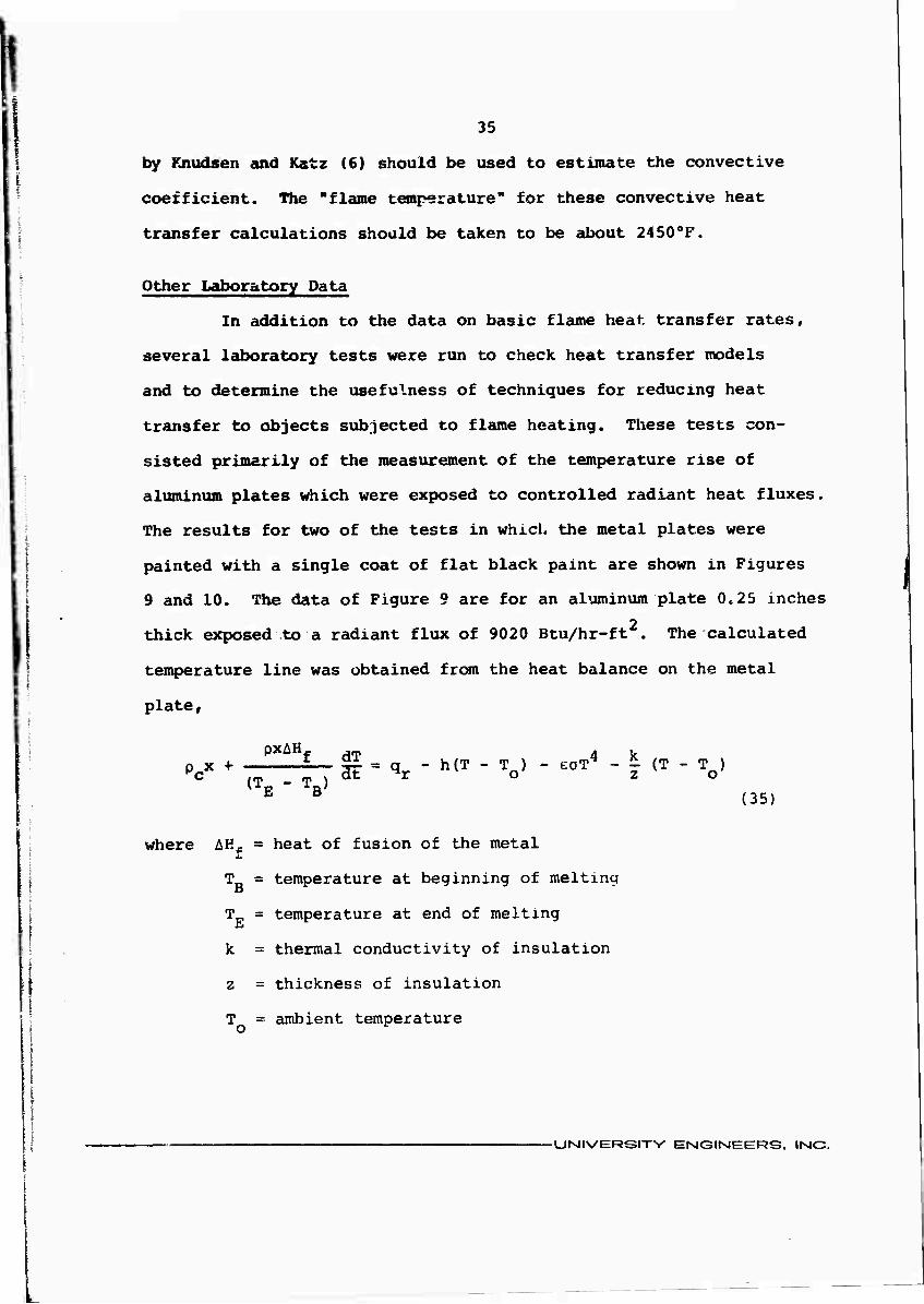
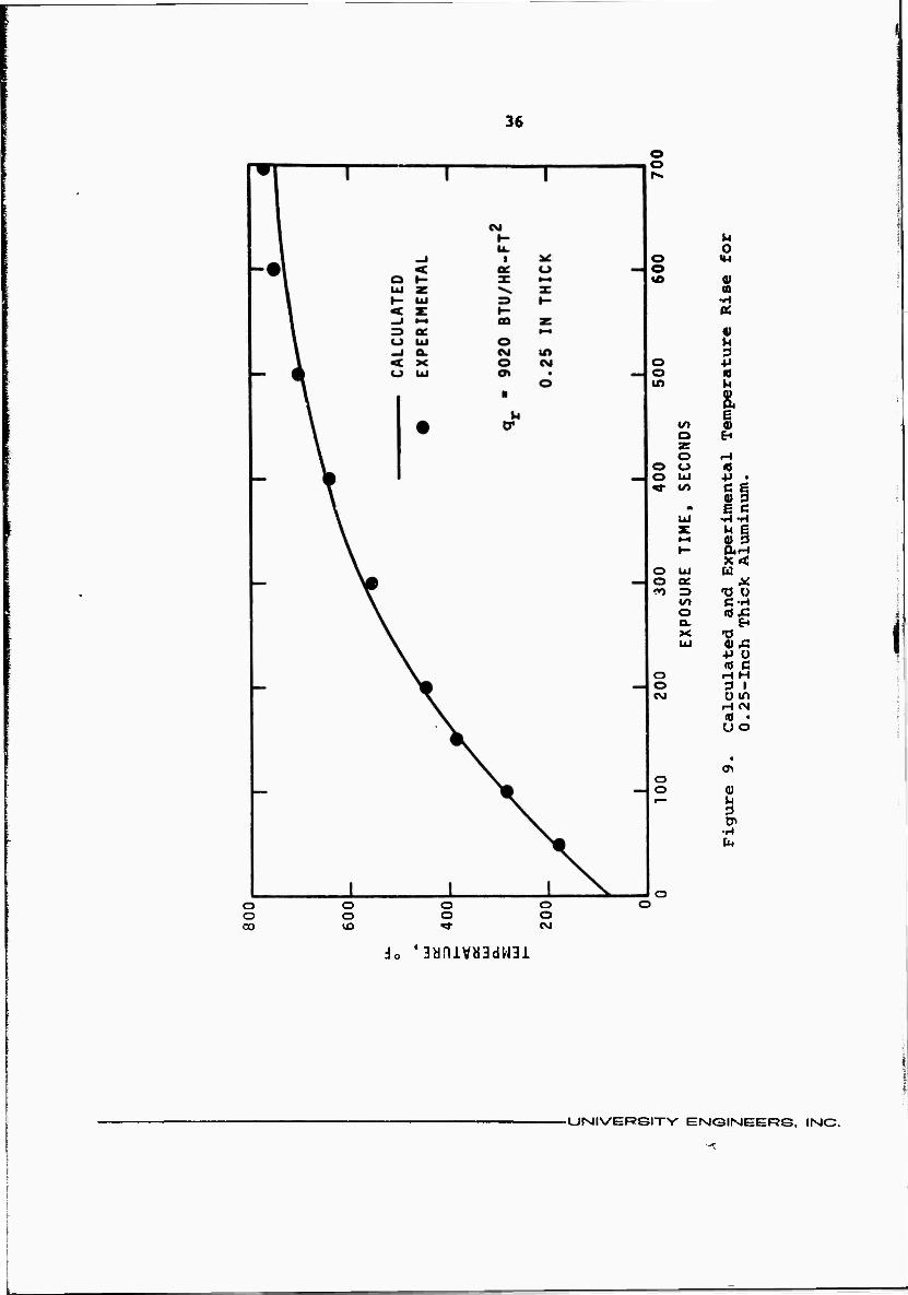
9 and 10, The data of Figure 9 are for an aluminum plate 0.25 inches
2 thick exposed to a radiant flux of 9020 Btu/hr-ft . The calculated
temperature line was obtained from the heat balance on the metal
plate,
pxAHf ,_. 4 k PcX + (T -T) al = qr - h(T ' V - eoT " I (T - V E B (35)
where AK^. = heat of fusion of the metal
T_ = temperature at beginning of melting o
T = temperature at end of melting
k = thermal conductivity of insulation
z = thickness of insulation
T = ambient temperature o
-UNIVERSITY ENGIMEERS, IMC.
36
o o
0 o »M o «o 0) n
0)
3 o +J o « m h
1 Ul 0) o ^ z o rH
o o A o UJ +> • * fcO c e
0) 3 * E C UJ •H-rl z ^ § 1—1 a) 3 t- CU-H
o LU u o QC A: <n Z3 •o o
CO C-H o «ox o. EH X •0 UJ <0 Xi
o H H o 3 1 CNJ
iH «N «0 •
•
o o 0)
O o O o o o o o 00 «3 t CM
•aanivbBdwai
-UNIVERSITY EMGINEERS. IMC.
-^
37
I
o r»i
0
0) (0
o o a>
o «/) f-> 00 o
z r-i o (0 <_> 4J • IxJ C R Ul (Ü 3
E C •» -r^-H UJ ^ E
o 2: 0) P to *~t a-n
h~
LU a ec T) O => C-H CO •ox: 0 EH 0. n
o X a» x: ^i- LU
Cal
cula
t 0.1
0-I
nc
o CVJ •
0 rH
0) U 0 tp
•H o fu,
io 43aniv«3dwn
UNIVERSITY ENGINEERS, INC.
38
The al iminum saisple was backed on the unexposed side by insulation
to minimize heat loss. The average absorptance of the exposed
surface was taken as 0.8 based on spectral reflectance data. The
emittance was assumed to be 1.0 because of the relatively low
plate temperatures and the low spectral reflectances of the paint
measured at longer wavelengths. The convective heat transfer
coefficient was based on steady state heat transfer data. Agree-
ment of calculated and measured heat fluxes is quite good for the
data of Figure 9. The beginning of melting, which was taken to be
about 9000F in the model, was not reached during the test.
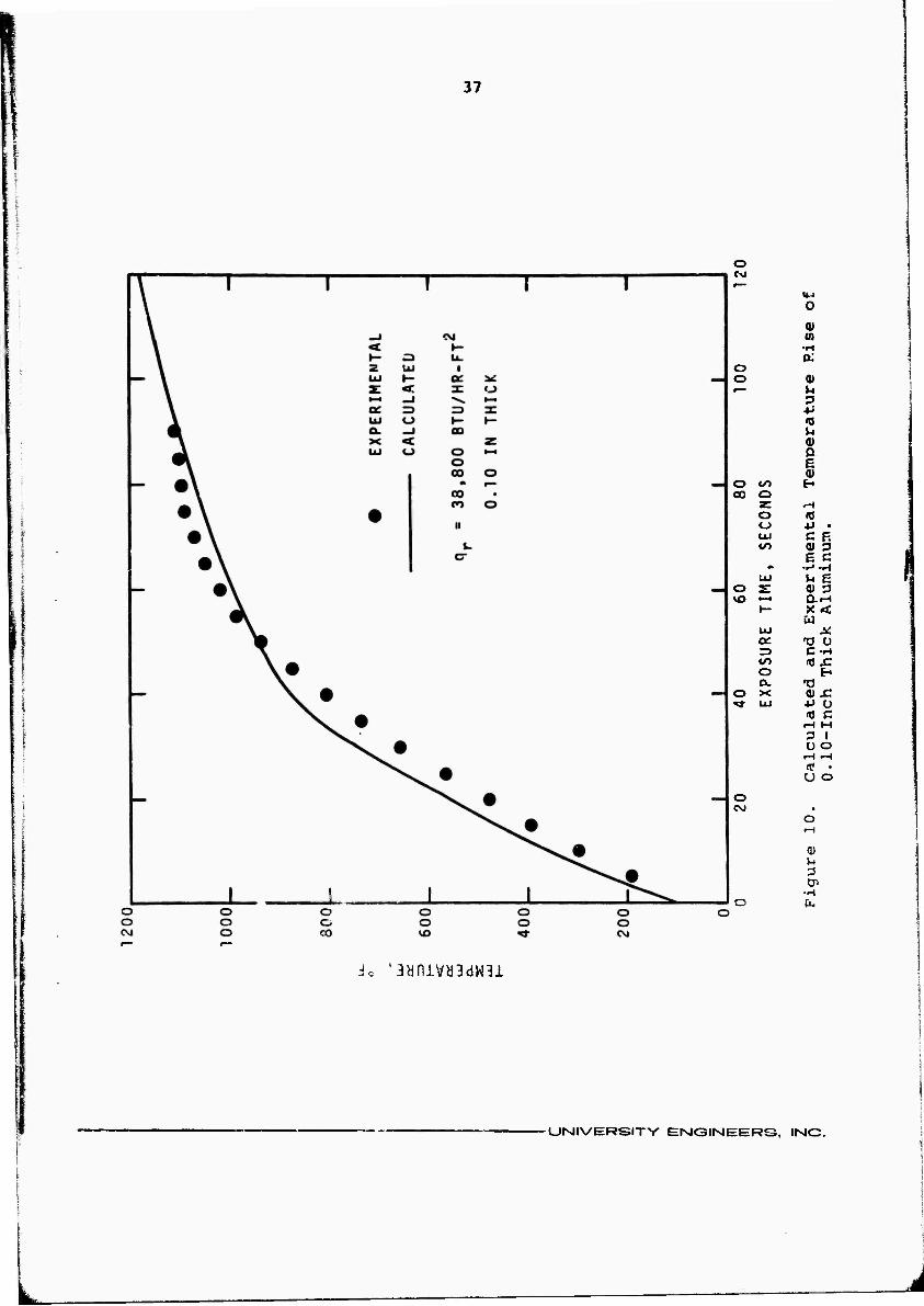
The radiant flux in Figure 9 is well below the maximum
found inside a fire. Figure 10 shows calculated and experimental
2 results for an incident radiant flux of 38,800 Btu/hr-ft . The
results show a little poorer comparison, with the calculated
temperature rising a little faster than the experimental tempera-
ture initially, but leveling off faster once melting begins.
Part of the difference may be due to changes in thermal"properties
of the aluminum as it is heated, and part may be due to the assump-
tion in the calculations of linear heat absorption during melting.
The important result is that the melting (or failure) time of the
aluminum plate occurs less than a minute after exposure if the
0,10 in thick plate is unprotected or uncooled. This calculation
illustrates the validity of the calculational procedures presented
in the mathematical models in the earlier sections of this report,,
During the direct flame contact heat transfer experiments
the temperature of a small cylindrical thermocouple well adjacent
■UNIVERSITV EMGINEERS. INC.
39
to the heat transfer probe was monitored continuously. (The
steady state temperatures of the small cylinder were used to
calculate the "flame temperature.") The temperature rise of the
cylinder was calculated using an equation similar to Equation 35,
but it was modified by deleting the melting term and correcting
for the different area to volume ratio of the cylinder. Figures 11
through 13 show the results of the calculations and compare them
with the measured temperature rise data. Figure 11 is for the
nominal 12-inch fires, and shows the poorest agreement of calcu-
lated and measured results. Figure 12, for 18-inch fires and
Figure 13, for 24-inch fires, show better comparison. The calcu-
lated temperature always rises faster than the measured tempera-
ture. The primary reason for the faster rise is that the calcu-
lated temperature rise is based on the maximum fire size being
reached instantaneously. In the measured temperatures the fire
was ignited and a few minutes heating time was required for the
fuel to be heated and the fire to reach maximum size. Figure 13
also shows one heating curve where the fire became unstable and
leaned over during the warmup period. The fire was stabilized and
the thermocouple well was then heated to its steady state temperature
The calculations assume that the cylinder has a uniform temperature
throughout. However, since stainless steel has a relatively low
thermal conductivity (compared to aluminum, for example) the
interior temperature may be 20 to 40oF lower than the surface
temperature. This difference is a minor factor in many heat
transfer considerations because it seldom limits the heat transfer
rate to a significant degree.
•UNIVERSITV ENIGIMEERS, IMC.

4C
Cd ev.«
o CM
CM UJ
0) a> u
-H fc,
I a.
u c H
I
u 0
4-1
(0 0) n 3 4J 10 u
ß 0)
S
a 3 0 u o
EH
0) M
Cn •H fa
o o O o o O O o o O o o O O «d- <M O 00 *£> <*• CSJ
•BynjLvasdwai
- UNIVERSITY ENG1MEERS, INC.

: ■I
i
ISJ
u 00 ■H
■«»■
1 0.
■4> x: r- * ü
c IH
1 00
«* u 0
Ol u CVJ LU 3 r— y- 4J
3 (0 z »4 l-H 0) s: a
•• 0) o LU E- •— s:
i—i .H »-
1 0)
00 r-l a 0 u
ID 0)
• rH
«3-
U D
■H Ix,
CM
O
O
do 'aynivyadWBi
-UMIVERSITY EMGIMEER£i. IMC.

42
T I es.
o CM
«/I CM UJ
t—*
O tu
0)
I
o c M I
*>• tM
U o
4J RJ
0) a E 0) EH
0)
at r-l a O Ü o E u 0)
•H
Ho '3bniVa3dW3i
-UMIVERSITY ENGIMEERS IMO.
43
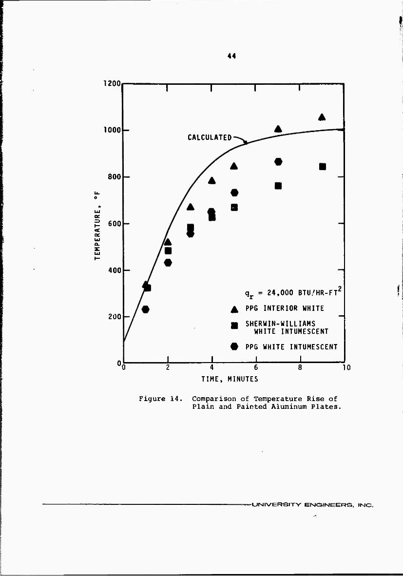
Several aluminum plates were coated with intumescent
paint and exposed to constant radiant heat fluxes. The aluminum
| temperature was measured continuously. Figure 14 shows the results i
for white paint on a 0.25-inch thick sample. The solid line was
calculated as described previously for other aluminum samples.
It agrees fairly well with the r *sured temperatures for an
aluminum sample painted with ordinary PPG interior white latex
paint. Samples painted with both PPG and Sherwin-Williams intum-
escent paint had slower temperature rise rates. The foaming action
of the PPG intumescent paint occurred at about 2800F, and the
Sherwin-Williams sample foamed at about 330CF, The PPG sample
heated more slowly at first, but the foam apparently was a little
l.^ss effective than the Sherwin-Williams foam at higher temperatures,
The PPG sample temperature rose faster at higher temperatures.
• The temperatures at which foaming occurred for the intumes-
cent painted aluminum samples was not consistent, even for the
same paint. Foaming occurred as low as 2800F and as high as 540CF#
depending on the brand of paint and the pigments used for coloring.
Both of the paints tried were designed for interior building use,
and there are probably other intumescent paints which will give
better protection for use on metals. If protection is desired
for tanks, the foaming and insulating reaction must occur at suf-
ficiently low temperatures to prevent boiling of the tank contents.
The foam layer must then withstand the high temperature of the fire
if it is to insulate the tank after foaming has occurredo
-UMIVERSITV ErslGINIEERS, IMC.
44
1200
1000 CALCULATED
800
600
400
2Ü0
qr = 24.000 BTU/HR-FT'
^ PPG INTERIOR WHITE
■ SHERWIN-WILLIAMS WHITE INTUMESCENT
# PPG WHITE INTUMESCENT
1 1 1 4 6
TIME, MINUTES
0
Figure 14. Comparison of Temperature Rise of Plain and Painted Aluminum Plates.
-CJMIVERSITY ENGIMEERS, INC.
45
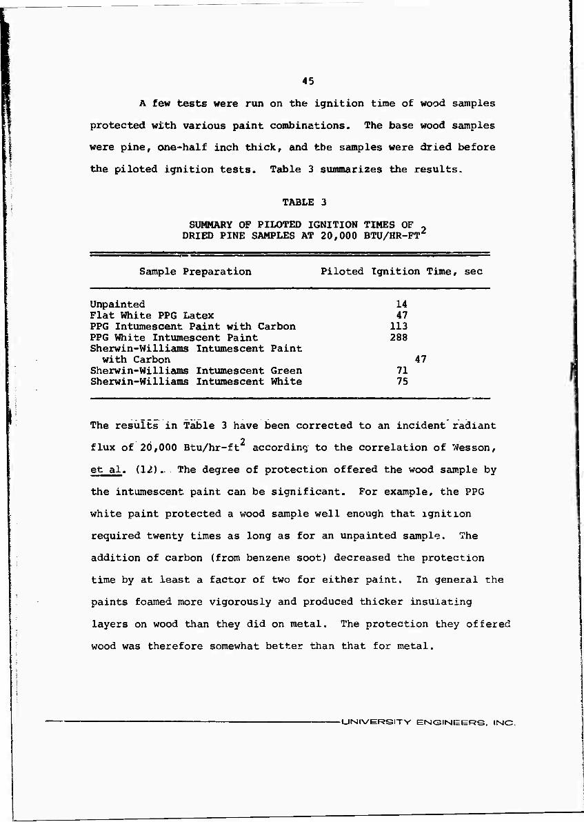
A few tests were run on the ignition time of wood samples
protected with various paint combinations. The base wood samples
were pine, one-half inch thick, and the samples were dried before
the piloted ignition tests. Table 3 summarizes the results.
TABLE 3
SUMMARY OF PILOTED IGNITION TIMES OF - DRIED PINE SAMPLES AT 20,000 BTU/HR-FT^
Sample Preparation Piloted Ignition Time, sec
Unpainted 14 Flat White PPG Latex 47 PPG Intumescent Paint with Carbon 113 PPG White Intumescent Paint 288 Sherwin-Williams Intumescent Paint with Carbon 47
Sherwin-Williams Intumescent Green 71 Sherwin-Williams Intumescent White 75
The results in Table 3 have been corrected to an incident radiant
2 flux of 20,000 Btu/hr-ft according to the correlation of Wesson,
et al. (12).. The degree of protection offered the wood sample by
the intumescent paint can be significant. For example, the PPG
white paint protected a wood sample well enough that ignition
required twenty times as long as for an unpainted sample. The
addition of carbon (from benzene soot) decreased the protection
time by at least a factor of two for either paint. In general the
paints foamed more vigorously and produced thicker insulating
layers on wood than they did on metal. The protection they offered
wood was therefore somewhat better than that for metal.
-UNIVERSITY ENGIMEERS. IMC.
TEST PLAN
The work proposed by these fire tests is designed to
provide confirmatory measurements of the heat transfer rates from
large fires to a tank completely surrounded by the fire. Three
fire tests are proposed, each using a tank nearly filled with
water. The temperature rise of the water will be used to measure
the heat transfer rate to the tank contents. The sizes of the
tanks to be used will depend on their availability. The largest
tank should contain about 10,000 gal, and the two smaller tanks
should ideally contain about 2500 gal and 500 gal in order to
obtain a good distribution of tank sizes.
Each of the three fire tests will consist of one large
tank plus several smaller test panels or containers. The large
2 tank will be situated in a test pit approximately 5000 ft in
area. The tank must be located in the test pit so that the
flame zone is at least 15 ft thick between the tank wall and the
outside of the fire or other test equipment. Ideally, the tank
should also be at least 15 ft above the liquid fuel surface
during the tests. Practically, it may not be possible to mount
the tank 15 ft above the fuel surface and still keep it within
the flame zone, unless a larger fire is used. In addition, the
ambient wind must be less than about 10 mph or the flame will
lean to such aji extent that full coverage of the test vessel
will not be obtained.
46
-UiNJIVERSITV ENGINEERS, IMC.
47
The tanks will be instrumented with thermocouples to
monitor both the tank wall temperature and the temperature of the
water inside the tank. Up to 12 thermocouples will be used for
these measurements. In addition, two heat flux transducers will
be mounted on or near the tank. One of these will measure only
the radiant heat flux and the other will measure both radiant and
convective flux. The measurements from these transducers can be
used for comparison with the test results from the tank. The fires
will burn about 20 min and provide a temperature rise of about
100oF in the tank. Tank pressure will be monitored continuously
with a pressure transducer.
The tanks to be used during the test program will be
chosen by the Committee and furnished either by the Committee or
by other interested parties.
Several smaller test panels or containers will be used
during each test. These must be positioned so that they do not
interfere with the tank fire tests, but at the same time, they
must also receive full heat from the fire. Each test panel will
be designed to provide support for one or more experiments m
which a topic of interest is investigated. For example, one
panel might contain a number of samples coated with intumescent
paint to measure the degree of protection that they might offer
during a fire. Another panel might contain insulated samples
to compare various forms of insulation. Yet another test panel
might support a small-scale heat transfer probe, which could
be used to aid in determining whether the size of the fire is
-UISIIVERSITY ErMGINIEERS, IMC.

48
important in scaling convective heat transfer rates. Other experi-
ments suggested by the committee could also be tested on the snail
test panels.
Four radiation heat flux transducers will be placed outside
the fire. One of these will be restricted to a narrow view angle
to measure the maximum surface flux from the fire. The other three
will be wide angle transducers and will measure the incident flux
at some location outside the fire. These data will be used to
support prediction of heat transfer rates to objects outside the
fire.
If the Committee decides that a full scale test using a
vented tank which contains a flammable liquid is necessary, the
test will be run following completion of the three tests using
the water-filled tanks. The test setup would remain essentially
the same, except that the duration of the test would have to be
about three times as long to ensure operation of the venting
device. For such a test, fuel would either have to be supplied
to the test area continuously or the test pit would hcwe-to be
about three feet deep. The logistics of running such a test
become more difficult as the duration of the test increases,
primarily because of the fuel supply problem.
The size of the fires, their long duration with respect
to ordinary test fires, and the costs of building firo test grounds
make it imperative to attempt to conduct the full scale tests at
an existing fire testing facility. There are several test facilities
that might be used, with the approval of the facility owners, some
-UNIVERSITY EISK3INEERS, IMG.

49
private and some government-owned. It is anticipated that the
companies or agencies owning the fire test facilities would
cooperate in the fire tests since they have been willing to do
so in the past. Actual negotiations with them must wait until
formal approval of the program. The cost estimate for the field
tests is submitted separately.
■UNIVERSITY ENGIMEERS, IMC.

REFERiSNCES
1. Atallah, S., and D. S. Allan, "Safe Separation Distances from Liquid Fuel Fires," Fire Technology, 1_, 47 (1971).
2. Bader, B. E., "Heat Transfer in Liquid Hydrocarbon Fuel Fires,' Proceedings, International Symposium for Packaging and Transportation of Radioactive Materials, Sponsored by Sandia Corp. and U. S. Atomic Energy Commission, SC-^R- 65-98, Albuquerque, New Mexico (12-15 January 1965).
3. Burgess, D., and J. Grumer, "Comments on 'The Burning Rate of Liquid Fuels from Open Trays by Natural Convection' by D. B. Spalding," Fire Research Abstracts and Reviews, 4, 236 (1962).
4. Copley, J. A., "An Analytical Method for Predicting the Temperature-Time History of a Hollow Cylinder Enveloped in Flames," Technical Report No 2073, U. S. Naval Wea- pons Laboratory, Dahlgren, Virginia (December 1966), AD 804 084.
5. Duggan, J. J., G. H. Gilmour, and P. F. Fisher, "Venting of Tanks Exposed to Fire," National Fire Protection Associa- tion Quarterly, 37, 131 (1943).
6. Knudsen, J. G., and D. L. Katz, Fluid Dynamics and Heat Transfer, McGraw-Hill, New York (1958).
7. Law, M., "Structural Fire Protection in the Process Industry," Building, 86-90 (18 July 1969).
8. Love, T. J., Radiative Heat Transfer, Merrill Publishing Co., Columbus, Ohio (1968).
9. Neill, D. T., J. R. Welker, and C. M. Sliepcevich, "Direct Contact Heat Transfer from Buoyant Diffusion Flames," J. Fire and Flammability, 1^ 289 (1970).
10. Rasbash, D. J., Z. E. Rogowski, and G. W. V. Stark, "Proper- ties of Fires of Liquids," Fuel, 35, 94 (1956).
11. Rein, R. G., C, M, Sliepcevich, and J. R. Welker, "Radiation View Factors for Tilted Cylinders," J. Fire and Flamma- bility, 1, 140 (1970).
12. Wesson, H. R., J. R. Welker, and C. M. Sliepcevich, "The Piloted Ignition of Wood by Thermal Radiation," Combustion and Flame, To be published (1971). '
50
•UMIVERSITY ENGINEERS, INC.