HVI-TEST SETUP FOR DEBRIS DETECTOR VERIFICATIONelib.dlr.de/87904/1/7a.O-3_bauer.pdf · HVI-TEST...
7
HVI-TEST SETUP FOR DEBRIS DETECTOR VERIFICATION Waldemar Bauer (1) , Oliver Romberg (1) , Carsten Wiedemann (2) , Robin Putzar (3) , Gerhard Drolshagen (4) , Peter Vörsmann (2) (1) German Aerospace Center (DLR), Institute of Space Systems, Department of System Analysis Space Segment, Bre- men, Germany, [email protected], [email protected] (2) Technical University of Braunschweig, Institute of Aerospace Systems, Braunschweig, Germany, c.wiedemann@tu- bs.de, [email protected] (3) Fraunhofer-Institute for High-Speed Dynamics, Ernst-Mach-Institut, EMI, Freiburg, Germany, [email protected], (4) ESA/ESTEC, Space Environments & Effects Section, Noordwijk, The Netherlands, [email protected] ABSTRACT Risk assessment concerning impacting space debris or micrometeoroids with spacecraft or payloads can be performed by using environmental models such as MASTER (ESA) or ORDEM (NASA). The validation of such models is per- formed by comparison of simulated results with measured data. Such data can be obtained from ground-based or space- based radars or telescopes, or by analysis of space hardware (e.g. Hubble Space Telescope, Space Shuttle Windows), which are retrieved from orbit. An additional data source is in-situ impact detectors, which are purposed for the collec- tion of space debris and micrometeoroids impact data. In comparison to the impact data gained by analysis of the re- trieved surfaces, the detected data contains additional information regarding impact time and orbit. In the past, many such in-situ detectors have been developed, with different measurement methods for the identification and classification of impacting objects. However, existing detectors have a drawback in terms of data acquisition. Generally the detection area is small, limiting the collected data as the number of recorded impacts has a linear dependence to the exposed area. An innovative impact detector concept is currently under development at the German Aerospace Centre (DLR) in Bre- men, in order to increase the surface area while preserving the advantages offered by dedicated in-situ impact detectors. The Solar Generator based Impact Detector (SOLID) is not an add-on component on the spacecraft, making it different to all previous impact detectors. SOLID utilises existing subsystems of the spacecraft and adapts them for impact detec- tion purposes. Solar generators require large panel surfaces in order to provide the spacecraft with sufficient energy. Therefore, the spacecraft solar panels provide a perfect opportunity for application as impact detectors. Employment of the SOLID method in several spacecraft in various orbits would serve to significantly increase the spatial coverage con- cerning space debris and micrometeoroids. In this way, the SOLID method will allow the generation of a large amount of impact data for environmental model validation. The ground verification of the SOLID method was performed at Fraunhofer EMI. For this purpose, a test model was developed. This paper focuses on the test methodology and devel- opment of the Hypervelocity Impact (HVI) test setup, including pretesting at the German Aerospace Centre (DLR), Bremen. Foreseen hardware and software for the automatic damage assessment of the detector after the impact are also presented. Keywords: Space Debris, SOLID, impact detector, environmental model validation. 1. INTRODUCTION Space activities over the past 6 decades have led to a progressive increase in the creation of space debris. Im- pacting debris can damage or even destroy spacecraft and payloads. The mission risk analysis can be per- formed with space debris environmental models such a MASTER or ORDEM. These models allow the estima- tion of the space debris flux into the spacecraft. MAS- TER, for instance, uses mathematical methods in com- bination with measured data for model generation and validation. There are several databases of space envi- ronment data; however the available data is very limited and is valid only for specific objects, orbits and time pe- riods. The Space Surveillance Network (SSN) catalogue contains space debris data for low Earth orbit (LEO), for objects exceeding ~10cm; and geostationary orbit (GEO), for objects exceeding ~1m. Sporadic “spot- check” campaigns are able to provide data in LEO for debris particles exceeding ~2mm, and in GEO for space
Transcript of HVI-TEST SETUP FOR DEBRIS DETECTOR VERIFICATIONelib.dlr.de/87904/1/7a.O-3_bauer.pdf · HVI-TEST...
HVI-TEST SETUP FOR DEBRIS DETECTOR VERIFICATION
Waldemar Bauer(1)
, Oliver Romberg(1)
, Carsten Wiedemann(2)
, Robin Putzar(3)
,
Gerhard Drolshagen(4)
, Peter Vörsmann(2)
(1) German Aerospace Center (DLR), Institute of Space Systems, Department of System Analysis Space Segment, Bre-
men, Germany, [email protected], [email protected] (2)
Technical University of Braunschweig, Institute of Aerospace Systems, Braunschweig, Germany, c.wiedemann@tu-
bs.de, [email protected] (3)
Fraunhofer-Institute for High-Speed Dynamics, Ernst-Mach-Institut, EMI, Freiburg, Germany,
[email protected], (4)
ESA/ESTEC, Space Environments & Effects Section, Noordwijk, The Netherlands,
ABSTRACT
Risk assessment concerning impacting space debris or micrometeoroids with spacecraft or payloads can be performed
by using environmental models such as MASTER (ESA) or ORDEM (NASA). The validation of such models is per-
formed by comparison of simulated results with measured data. Such data can be obtained from ground-based or space-
based radars or telescopes, or by analysis of space hardware (e.g. Hubble Space Telescope, Space Shuttle Windows),
which are retrieved from orbit. An additional data source is in-situ impact detectors, which are purposed for the collec-
tion of space debris and micrometeoroids impact data. In comparison to the impact data gained by analysis of the re-
trieved surfaces, the detected data contains additional information regarding impact time and orbit. In the past, many
such in-situ detectors have been developed, with different measurement methods for the identification and classification
of impacting objects. However, existing detectors have a drawback in terms of data acquisition. Generally the detection
area is small, limiting the collected data as the number of recorded impacts has a linear dependence to the exposed area.
An innovative impact detector concept is currently under development at the German Aerospace Centre (DLR) in Bre-
men, in order to increase the surface area while preserving the advantages offered by dedicated in-situ impact detectors.
The Solar Generator based Impact Detector (SOLID) is not an add-on component on the spacecraft, making it different
to all previous impact detectors. SOLID utilises existing subsystems of the spacecraft and adapts them for impact detec-
tion purposes. Solar generators require large panel surfaces in order to provide the spacecraft with sufficient energy.
Therefore, the spacecraft solar panels provide a perfect opportunity for application as impact detectors. Employment of
the SOLID method in several spacecraft in various orbits would serve to significantly increase the spatial coverage con-
cerning space debris and micrometeoroids. In this way, the SOLID method will allow the generation of a large amount
of impact data for environmental model validation. The ground verification of the SOLID method was performed at
Fraunhofer EMI. For this purpose, a test model was developed. This paper focuses on the test methodology and devel-
opment of the Hypervelocity Impact (HVI) test setup, including pretesting at the German Aerospace Centre (DLR),
Bremen. Foreseen hardware and software for the automatic damage assessment of the detector after the impact are also
presented.
Keywords: Space Debris, SOLID, impact detector, environmental model validation.
1. INTRODUCTION
Space activities over the past 6 decades have led to a
progressive increase in the creation of space debris. Im-
pacting debris can damage or even destroy spacecraft
and payloads. The mission risk analysis can be per-
formed with space debris environmental models such a
MASTER or ORDEM. These models allow the estima-
tion of the space debris flux into the spacecraft. MAS-
TER, for instance, uses mathematical methods in com-
bination with measured data for model generation and
validation. There are several databases of space envi-
ronment data; however the available data is very limited
and is valid only for specific objects, orbits and time pe-
riods. The Space Surveillance Network (SSN) catalogue
contains space debris data for low Earth orbit (LEO), for
objects exceeding ~10cm; and geostationary orbit
(GEO), for objects exceeding ~1m. Sporadic “spot-
check” campaigns are able to provide data in LEO for
debris particles exceeding ~2mm, and in GEO for space
debris larger than ~10cm. These campaigns use a net-
work of radars and optical telescopes to generate snap-
shots of the space environment. Adequate validation for
environmental models can be performed from these
campaigns and various catalogues for LEO objects larg-
er than 5mm (from radar measurements), and for GEO
objects exceeding 10cm (from optical telescope meas-
urements). Additionally, retrieved hardware provide a
representation of space debris smaller than 20µm up to
650km altitude [1].
However, the validity of the data collected is short-
lived, due to the dynamic nature of the space debris en-
vironment. Additionally, there are some regions where
little or even no data exists. The space debris in this re-
gion is undetected, as it is too small for ground based
radar and optical telescopes. Furthermore, it is large
enough that it has a low flux, making detection through
impact hardware retrieval rare. This problem is especial-
ly the case for space debris ranging in diameter from
20µm to 5mm, where in the case of MASTER2009, on-
ly data obtained from the LDEF-CME (Long Duration
Exposure Facility – Chemistry of Micrometeoroids Ex-
periment) was available for model validation. In addi-
tion, many objects above 650km in altitude and inclina-
tions outside of the range serviced by the space shuttle
(typically 28.5°) go undetected [1].
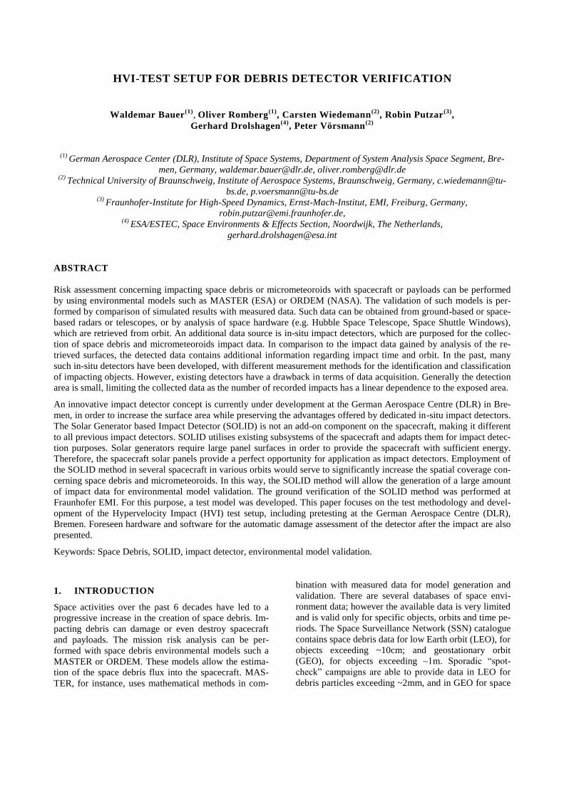
Figure 1 gives an overview of the space debris situation
as of 2009. The total quantities for various classes of
space debris objects derived from the MASTER2009
model, were provided by Carsten Wiedemann, Tech-
nical University of Braunschweig, Germany. Possible
options for data acquisition as well as the predicted
damage to spacecraft and payloads are outlined. A com-
parison of four different space debris environmental
models is shown to the right of Figure 1 [2], with dis-
crepancies obvious between the models even for well-
investigated areas. This is the case particularly for LEO
objects >100µm and >1cm. Studies, such as those pro-
vided in [2,3], have also uncovered large differences be-
tween various models and data. Therefore there is an
urgent need for more data, particularly for smaller ob-
jects that cannot be tracked (1mm to 1cm) by ground
surveillance.
Considering this need, an in-situ impact detector with a
large area is proposed. Adaptation of existing spacecraft
subsystems for in-situ impact detection allows cost-
effective and efficient deployment of detectors into var-
ious orbits, providing large spatial coverage of the space
environment. Measured data from such detectors can be
transmitted real time to ground stations for immediate
utilisation in space debris environmental modelling. The
Solar Generator based Impact Detector (SOLID) is un-
der development by the German Aerospace Centre
(DLR) in Bremen for this purpose. The SOLID detec-
tion method was submitted to Hypervelocity Impact
(HVI) testing for ground verification. This paper focus-
es on the test setup and provides an overview of the
SOLID concept. More detailed information on the theo-
retical background, manufacturing, and implementation
of SOLID can be found in [5,6,7,8].
Figure 1: Space debris environment [2,3,4]

2. SOLID IMPACT DETECTOR
The SOLID is a large-area impact detector which can be
flown in any orbit. Unlike most conventional detectors,
the proposed new concept utilises existing subsystems
of the spacecraft bus and adapts them for impact detec-
tion, as depicted in Figure 2. The electrical power sub-
system (EPS) and the attitude control subsystem (ACS)
are used for data acquisition. The data handling subsys-
tem (DH) and telemetry and telecommand subsystem
(TM&TC) perform data processing and data transfer to
Earth.
Figure 2: Spacecraft subsystems adaptation
The functional principle of SOLID is illustrated in Fig-
ure 3. The core component of the system is a solar gen-
erator (S/G) with photovoltaic cells (PV). An autono-
mous electronic box (E-BOX) is also implemented in
the interior of the spacecraft. A particle impacting the
solar generator can create an anomaly in power supply.
The E-BOX monitors the EPS for these events and
compares them to predefined impact disturbance behav-
iour. Once the anomaly was identified as an impact, the
solar generator structure (SGS) is analysed for damage.
From this analysis, the impact location and damage of
the SGS caused by impact is determined. The magni-
tude of the damage enables estimation of the incident
particle diameter. The ACS data is also analysed within
a predefined time after the impact in order of the dam-
age to ascertain the momentum transfer to the spacecraft
from the space debris or micrometeoroid impact. The
combination of the known impact position, the particle
diameter from SGS analysis and the momentum transfer
from ACS subsystem enables the determination of the
particle velocity.
The principal adaptation method of the standard SGS
for the purpose of impact detection is depicted in Figure
4. The SOLID concept modifies the insulation layer be-
hind the solar cells of commonly used S/G. The modi-
fied S/G integrates two layers of copper lines between
the insulation layers (usually Kapton). The two copper
layers are aligned in perpendicular directions, forming a
detection grid. In an impact event, the colliding particle
causes damage which can range in depth from the cover
glass layer down to the detection layer (DL). Conse-
quently cuts several copper lines in the grid. The num-
ber and position of the severed strips can be identified
by the analysis electronics and software (see the E-
BOX, Figure 3). The damage equations provided in [6,
7, 12, 13] can be used to estimate the diameter of the in-
coming particle.
Figure 3: Functional principle of SOLID concept

Figure 4: SG adaptation for SOLID concept
3. HVI TEST SETUP
Figure 5 shows the foreseen HVI-test setup. The SOLID
(including electronics system) is placed within the target
chamber. The oscilloscope, transient recorder, PC
(software interface), power supply, and sun simulator
(SSA) are placed outside the target chamber. Electrical
interfaces from the interior to the exterior of the target
chamber are provided by vacuum-convenient connect-
ors. The communication between the software on the
PC and the SOLID electronics occurs via an RS232 in-
terface. The power supply provides the detection elec-
tronics with a voltage of 7V.
Figure 5: HVI test setup
Plexiglass windows are used for high speed photog-
raphy, video and for illumination of the solar cells with
solar light. One target chamber window is used for high
speed cameras, and the second for the SSA. The SSA
light spot of ca. 200mm in diameter is conducted
through the 8mm plexiglass window and illuminates the
solar cells on the test panel. Figure 6 contains the solar
spectrum (ASTM E-490; American Society for Testing
and Materials), the spectrum of the SSA (Xe-Lamp) and
the transmission of the Plexiglass window foreseen for
the HVI tests.
Figure 6: Spectrum of the sun, of the SSA and the
transmittance of the target chamber window
[14,15,16]
In order to simulate the solar spectrum at operational
conditions, the illumination of the solar cells for the
HVI testing should occur within the light spectrum ca.
300-1800nm [8,9]. For the HVI testing GS0F00 Plexi-
glass was selected, despite the spectral transmission var-
iation with the wave length, with some frequencies
transmitted only few percent. Figure 6 shows the spec-
trum of a comparable Plexiglass, for which the spectral
transmission was provided by the manufacturer.
Figure 7 depicts the SOLID prototype manufactured for
concept verification through HVI testing. The SOLID
detection layer is made of polyimide, with dimensions
of 380mm x 255mm. Diodes were implemented on the
top side of the detection layer. The detection area was
covered by six solar cells, covering an area of 160.5mm
x 121mm. These dimensions are marginally smaller
than the foreseen dimensions of the detection grid for
impact detection (168mm x 120mm).
Figure 7: SOLID prototype for HVI testing
This discrepancy was caused by size limitations of the
polyimide used for detection layer manufacturing. The
detection layer is applied to the carbon-fibre-reinforced
polymer/aluminium (CFRP/Al) primary structure
(sandwich). The aluminium honeycomb was perforated
to allow venting of the encapsulated air, as the tests are
performed in vacuum environment.
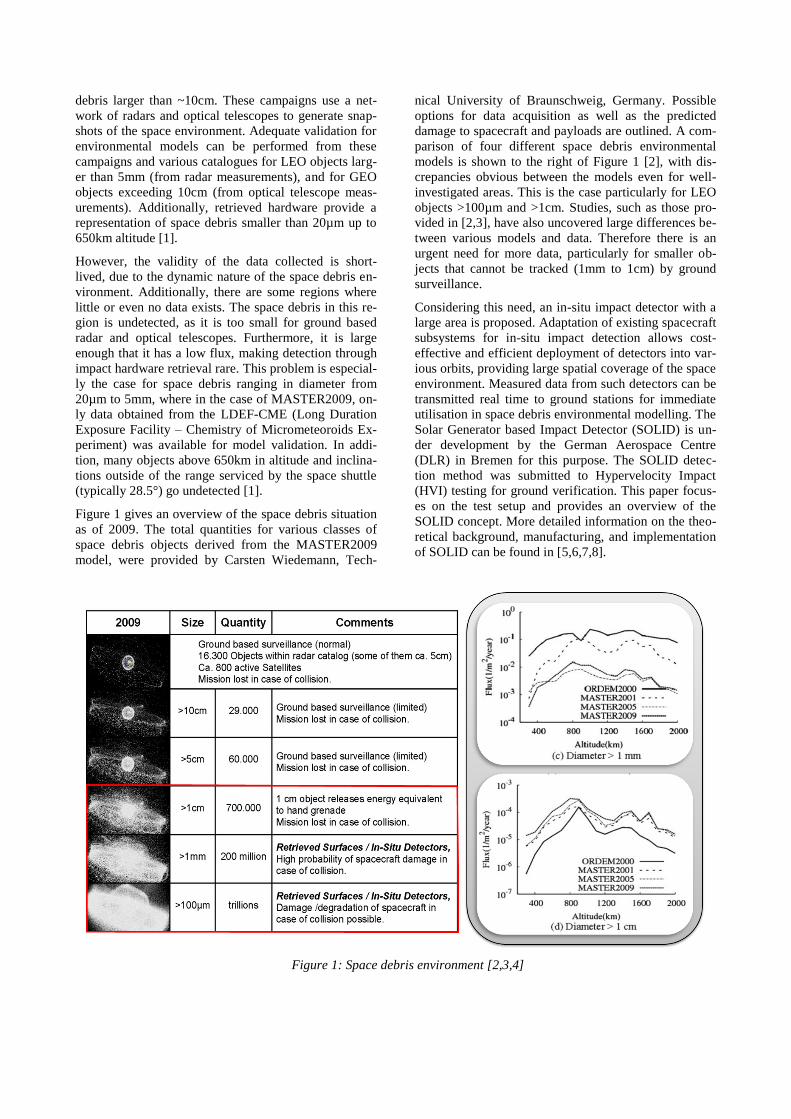
The automatic damage assessment on the solar panel af-
ter the impact is performed by the SOLID electronics.
The electronics can be subdivided into two functional
units: the pulse detection unit, which identifies the im-
pact; and the analysis unit, which performs the damage
analysis on the structure. Figure 8 shows the functional
principal of the pulse detector for ground testing.
Figure 8: Schematic principal of pulse detector
The voltage provided by solar cells (Uvz) is compared to
predefined reference voltage (Uref). In the event that the
solar cell voltage drops below the reference voltage, the
comparator provides the flip-flop with output signal
(Ua) and the flip-flop is switched from reset (R) to set
(S). If the flip-flop is set to (S), the output signal (Q) of
the-flip flop sets the interrupt (INT) on the microcon-
troller unit (MCU). After the triggering by the INT and
following a predefined time period, the MCU starts to
analyse the detection layer behind the solar cells. The
MCU checks the existence of all conductive lines by
switching the multiplexers (MUX) to the defined state
of the particular line. Figure 9 shows the schematic
principal of the analysis unit.
Figure 9: Schematic principal of analysis unit
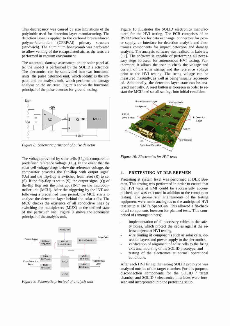
Figure 10 illustrates the SOLID electronics manufac-
tured for the HVI testing. The PCB comprises of an
RS232 interface for data exchange, connectors for pow-
er supply, an interface for detection analysis and elec-
tronics components for impact detection and damage
analysis. The analysis software was realised in Labview
[11]. The software is capable of performing all neces-
sary steps foreseen for autonomous HVI testing. Fur-
thermore, it allows the user to check the voltage and
current of the solar strings and the reference voltage
prior to the HVI testing. The string voltage can be
measured manually, as well as being visually represent-
ed. Additionally, the detection layer state can be ana-
lysed manually. A reset button is foreseen in order to re-
start the MCU and set all settings into initial condition.
Figure 10: Electronics for HVI-tests
4. PRETESTING AT DLR BREMEN
Pretesting at system level was performed at DLR Bre-
men. This testing was performed in order to ensure that
the HVI tests at EMI could be successfully accom-
plished, and was executed in addition to the component
testing. The geometrical arrangements of the testing
equipment were made analogous to the anticipated HVI
test setup at EMI’s SpaceGun. This allowed a fit-check
of all components foreseen for planned tests. This com-
prised of (amongst others):
- implementation of all necessary cables to the safe-
ty hoses, which protect the cables against the re-
leased ejecta at HVI testing,
- wire routing of components such as solar cells, de-
tection layers and power supply to the electronics,
- verification of alignment of solar cells to the firing
axis and mounting of the SOLID prototype, and
- testing of the electronics at normal operational
conditions.
After each HVI firing, the testing SOLID prototype was
analysed outside of the target chamber. For this purpose,
disconnection components for the SOLID / target
chamber and SOLID / electronics interfaces were fore-
seen and incorporated into the pretesting setup.
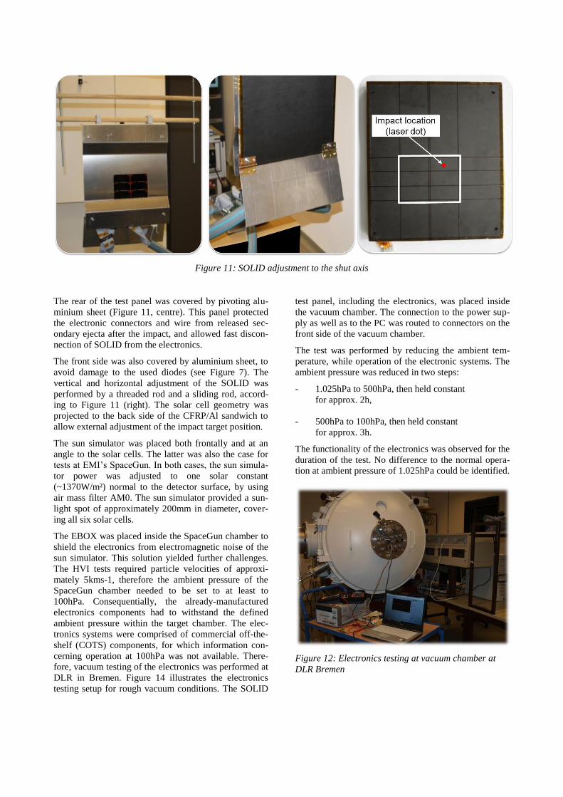
Figure 11: SOLID adjustment to the shut axis
The rear of the test panel was covered by pivoting alu-
minium sheet (Figure 11, centre). This panel protected
the electronic connectors and wire from released sec-
ondary ejecta after the impact, and allowed fast discon-
nection of SOLID from the electronics.
The front side was also covered by aluminium sheet, to
avoid damage to the used diodes (see Figure 7). The
vertical and horizontal adjustment of the SOLID was
performed by a threaded rod and a sliding rod, accord-
ing to Figure 11 (right). The solar cell geometry was
projected to the back side of the CFRP/Al sandwich to
allow external adjustment of the impact target position.
The sun simulator was placed both frontally and at an
angle to the solar cells. The latter was also the case for
tests at EMI’s SpaceGun. In both cases, the sun simula-
tor power was adjusted to one solar constant
(~1370W/m²) normal to the detector surface, by using
air mass filter AM0. The sun simulator provided a sun-
light spot of approximately 200mm in diameter, cover-
ing all six solar cells.
The EBOX was placed inside the SpaceGun chamber to
shield the electronics from electromagnetic noise of the
sun simulator. This solution yielded further challenges.
The HVI tests required particle velocities of approxi-
mately 5kms-1, therefore the ambient pressure of the
SpaceGun chamber needed to be set to at least to
100hPa. Consequentially, the already-manufactured
electronics components had to withstand the defined
ambient pressure within the target chamber. The elec-
tronics systems were comprised of commercial off-the-
shelf (COTS) components, for which information con-
cerning operation at 100hPa was not available. There-
fore, vacuum testing of the electronics was performed at
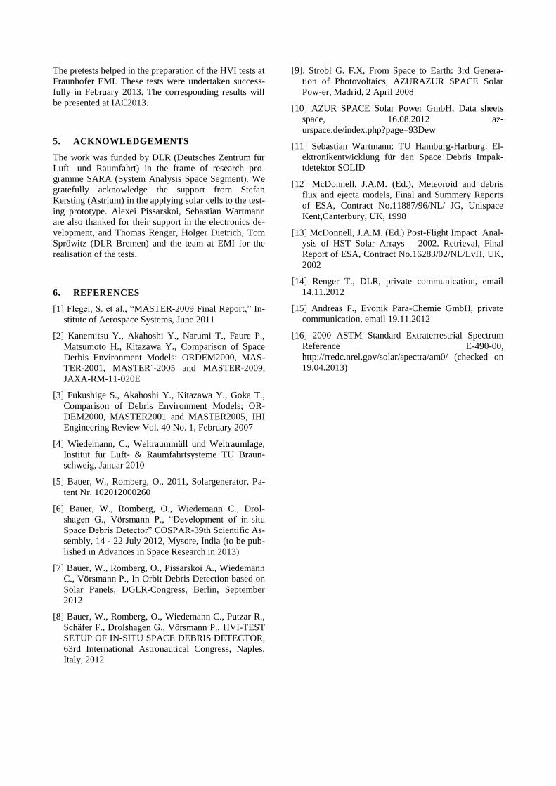
DLR in Bremen. Figure 14 illustrates the electronics
testing setup for rough vacuum conditions. The SOLID
test panel, including the electronics, was placed inside
the vacuum chamber. The connection to the power sup-
ply as well as to the PC was routed to connectors on the
front side of the vacuum chamber.
The test was performed by reducing the ambient tem-
perature, while operation of the electronic systems. The
ambient pressure was reduced in two steps:
- 1.025hPa to 500hPa, then held constant
for approx. 2h,
- 500hPa to 100hPa, then held constant
for approx. 3h.
The functionality of the electronics was observed for the
duration of the test. No difference to the normal opera-
tion at ambient pressure of 1.025hPa could be identified.
Figure 12: Electronics testing at vacuum chamber at
DLR Bremen
The pretests helped in the preparation of the HVI tests at
Fraunhofer EMI. These tests were undertaken success-
fully in February 2013. The corresponding results will
be presented at IAC2013.
5. ACKNOWLEDGEMENTS
The work was funded by DLR (Deutsches Zentrum für
Luft- und Raumfahrt) in the frame of research pro-
gramme SARA (System Analysis Space Segment). We
gratefully acknowledge the support from Stefan
Kersting (Astrium) in the applying solar cells to the test-
ing prototype. Alexei Pissarskoi, Sebastian Wartmann
are also thanked for their support in the electronics de-
velopment, and Thomas Renger, Holger Dietrich, Tom
Spröwitz (DLR Bremen) and the team at EMI for the
realisation of the tests.
6. REFERENCES
[1] Flegel, S. et al., “MASTER-2009 Final Report,” In-
stitute of Aerospace Systems, June 2011
[2] Kanemitsu Y., Akahoshi Y., Narumi T., Faure P.,
Matsumoto H., Kitazawa Y., Comparison of Space
Derbis Environment Models: ORDEM2000, MAS-
TER-2001, MASTER´-2005 and MASTER-2009,
JAXA-RM-11-020E
[3] Fukushige S., Akahoshi Y., Kitazawa Y., Goka T.,
Comparison of Debris Environment Models; OR-
DEM2000, MASTER2001 and MASTER2005, IHI
Engineering Review Vol. 40 No. 1, February 2007
[4] Wiedemann, C., Weltraummüll und Weltraumlage,
Institut für Luft- & Raumfahrtsysteme TU Braun-
schweig, Januar 2010
[5] Bauer, W., Romberg, O., 2011, Solargenerator, Pa-
tent Nr. 102012000260
[6] Bauer, W., Romberg, O., Wiedemann C., Drol-
shagen G., Vörsmann P., “Development of in-situ
Space Debris Detector” COSPAR-39th Scientific As-
sembly, 14 - 22 July 2012, Mysore, India (to be pub-
lished in Advances in Space Research in 2013)
[7] Bauer, W., Romberg, O., Pissarskoi A., Wiedemann
C., Vörsmann P., In Orbit Debris Detection based on
Solar Panels, DGLR-Congress, Berlin, September
2012
[8] Bauer, W., Romberg, O., Wiedemann C., Putzar R.,
Schäfer F., Drolshagen G., Vörsmann P., HVI-TEST
SETUP OF IN-SITU SPACE DEBRIS DETECTOR,
63rd International Astronautical Congress, Naples,
Italy, 2012
[9]. Strobl G. F.X, From Space to Earth: 3rd Genera-
tion of Photovoltaics, AZURAZUR SPACE Solar
Pow-er, Madrid, 2 April 2008
[10] AZUR SPACE Solar Power GmbH, Data sheets
space, 16.08.2012 az-
urspace.de/index.php?page=93Dew
[11] Sebastian Wartmann: TU Hamburg-Harburg: El-
ektronikentwicklung für den Space Debris Impak-
tdetektor SOLID
[12] McDonnell, J.A.M. (Ed.), Meteoroid and debris
flux and ejecta models, Final and Summery Reports
of ESA, Contract No.11887/96/NL/ JG, Unispace
Kent,Canterbury, UK, 1998
[13] McDonnell, J.A.M. (Ed.) Post-Flight Impact Anal-
ysis of HST Solar Arrays – 2002. Retrieval, Final
Report of ESA, Contract No.16283/02/NL/LvH, UK,
2002
[14] Renger T., DLR, private communication, email
14.11.2012
[15] Andreas F., Evonik Para-Chemie GmbH, private
communication, email 19.11.2012
[16] 2000 ASTM Standard Extraterrestrial Spectrum
Reference E-490-00,
http://rredc.nrel.gov/solar/spectra/am0/ (checked on
19.04.2013)