HVAC Economizers 101 Section #5 Typical Economizer ... · HVAC Economizers 101 Section #5 Typical...
26
HVAC Economizers 101 Section #5 Section #5 Typical Economizer Controls on Rooftop Units Rooftop Units that Utilize Honeywell Controls 5-1
Transcript of HVAC Economizers 101 Section #5 Typical Economizer ... · HVAC Economizers 101 Section #5 Typical...
HVAC Economizers 101Section #5Section #5
Typical Economizer Controls on Rooftop Units Rooftop Units
that Utilize Honeywell Controls
5-1
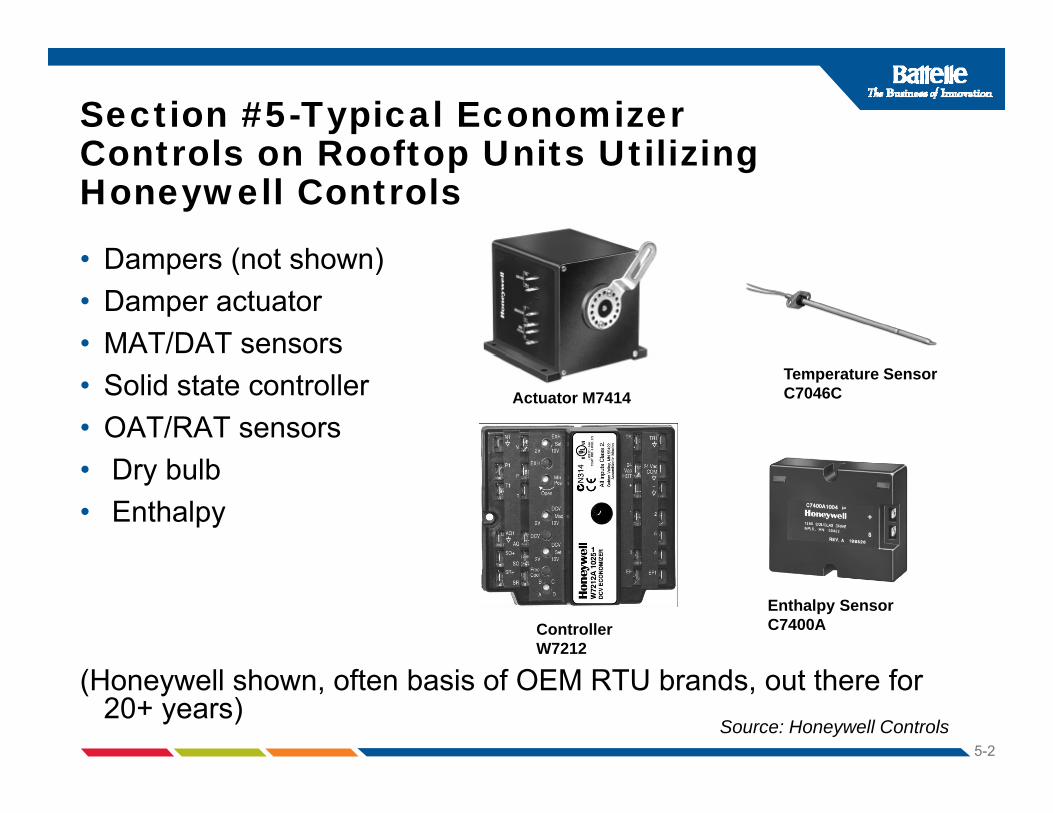
Section #5-Typical Economizer Controls on Rooftop Units Utilizing Controls on Rooftop Units Utilizing Honeywell Controls
D ( t h )• Dampers (not shown)• Damper actuator• MAT/DAT sensors• Solid state controller• OAT/RAT sensors
Actuator M7414Temperature Sensor C7046C
• Dry bulb• Enthalpy
Controller W7212
Enthalpy Sensor C7400A
5-2
(Honeywell shown, often basis of OEM RTU brands, out there for 20+ years)
Source: Honeywell Controls

Honeywell W7459 Economizer and Associated Control ComponentsAssociated Control Components
5-3

Basic Economizer Cycle Sequence Typical for Honeywell with only 1 stg. CoolingTypical for Honeywell with only 1 stg. Cooling(For typical packaged RTU with DX mechanical cooling)
On a First Call for Cooling From Commercial Thermostat (Y1)• Controller signal is routed to the economizer logic module.
IF THE OUTDOOR AIR IS SUITABLE FOR FREE COOLINGIF THE OUTDOOR AIR IS SUITABLE FOR FREE COOLING:• Actuator modulates the outdoor damper open until the room temperature
is cool enough to satisfy the call for cooling and maintain the desired set point When the mixed or discharge air is between 50 and 55 °F thepoint. When the mixed or discharge air is between 50 and 55 F, the actuator will hold the damper position. When the mixed or supply air goes below 50°F, the damper is modulated towards closed. When the mixed or supply air goes above 56°F, the damper is modulated towards open.pp y g p p
IF THE OUTDOOR AIR IS NOT SUITABLE FOR FREE COOLING:• The first stage of the cooling compressor is turned on and the dampers
are set to minimum for occupancy requirements
5-4
are set to minimum for occupancy requirements.

Basic Economizer Cycle Sequence Typical for Honeywell with one stage CoolingTypical for Honeywell with one stage Cooling(For typical packaged RTU with DX mechanical cooling)
5-5
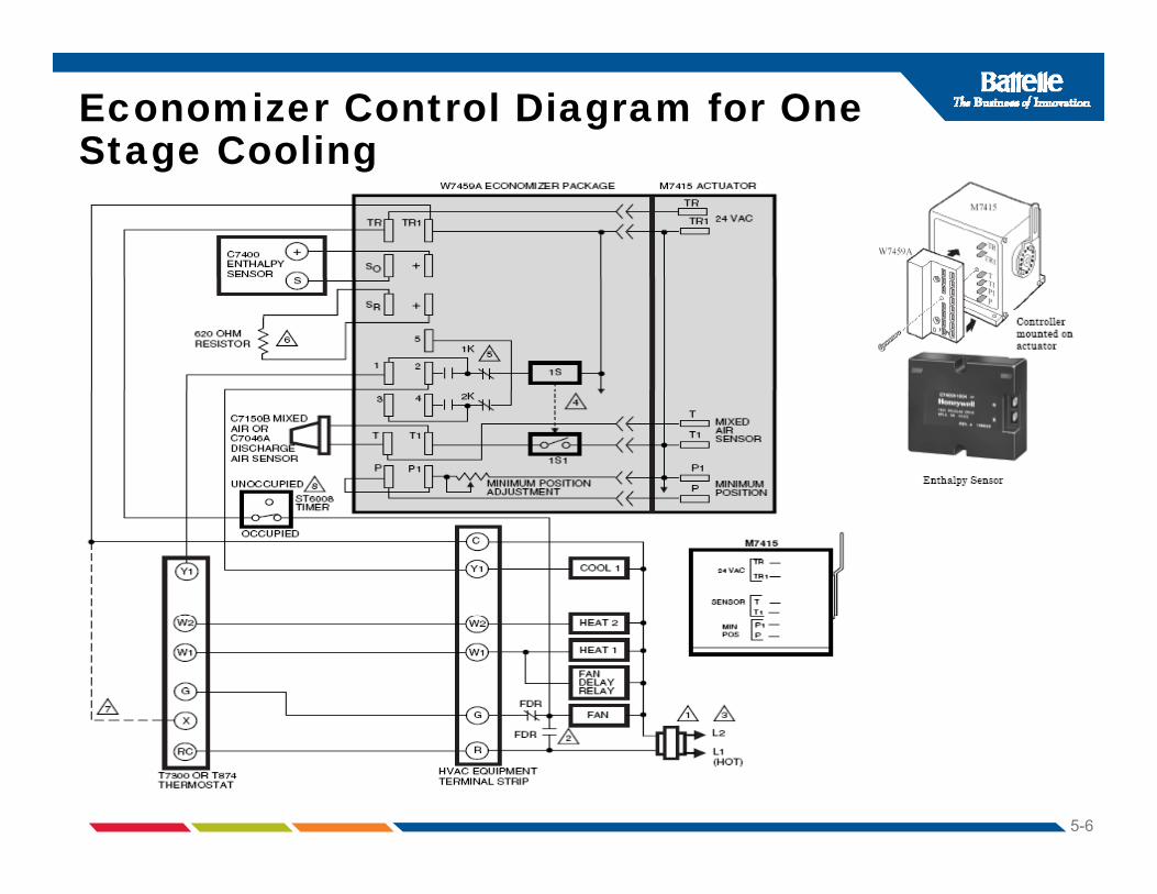
Economizer Control Diagram for One Stage Coolingg g
5-6

Basic Economizer Cycle Sequence Typical for Honeywell With Two Typical for Honeywell With Two Stage Cooling with EconomizerOn a Call for Single Stage CoolingOn a Call for Single Stage Cooling • Controller signal is routed to the economizer logic module to maintain space
temperature using outside air for free cooling.On a Call for Second Stage CoolingOn a Call for Second Stage Cooling• If the outdoor air is suitable for free cooling and the outside are dampers
are open, The economizer logic turns on the first stage of mechanical cooling for the second stage of cooling required by the commercial thermostat.
• If the outdoor air is not suitable for free cooling, The dampers are set to minimum for occupancy requirements, the first stage cooling compressor is on, and the logic module turns on the second stage of mechanical cooling if available. NOTE A i l th t t ith i i f t t f li i• NOTE: A commercial thermostat with a minimum of two stages of cooling is required. The first stage must be available for economizing if outside air is suitable.
5-7
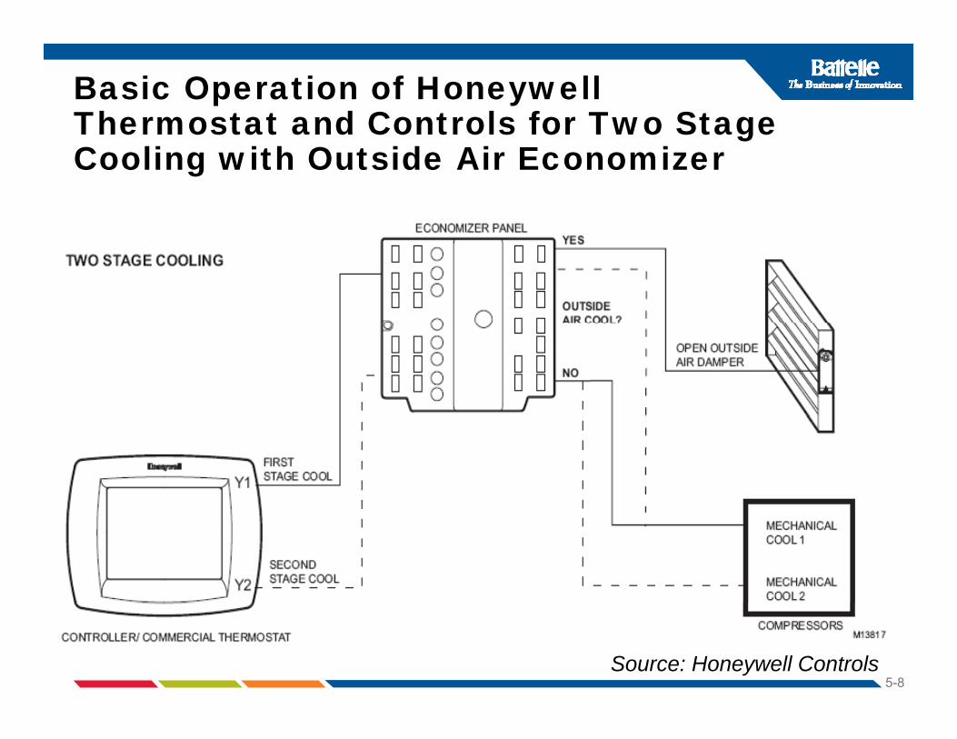
Basic Operation of Honeywell Thermostat and Controls for Two Stage gCooling with Outside Air Economizer
5-8Source: Honeywell Controls

Economizer Control Diagram for Two Stage Coolingg g
5-9
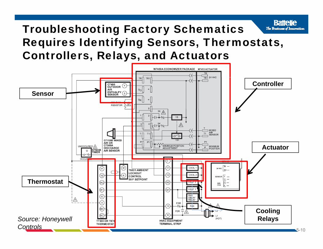
Troubleshooting Factory Schematics Requires Identifying Sensors, Thermostats, equ es de t y g Se so s, e ostats,Controllers, Relays, and Actuators
ControllerSensor
Actuator
Thermostat
5-10
Source: Honeywell Controls
Cooling Relays

ECONOMIZER INFORMATION (For completion by Service Technician)
ECONOMIZER Checkout Sheet (sample)ECONOMIZER INFORMATION (For completion by Service Technician)
Sensor Type(EM or SS/
Where Placed As found conditions (temp and RH (if
Output(DC Volts, mA, kΩ-- enter
t d d
Adjusted outputCleaned?R l d?SS/
DB or, h)*RH (if enthalpy))
expected and actual values)Book Actual
Replaced?Enter C or R
Outside Air
Mixed Air Temp
Discharge Air Temp
ReturnReturn
* EM=electromechanical, SS=solid state, DB= dry bulb, h=enthalpy (total energy)
Control Logic As Found ____Changeover ( A, B, C, D, DIP settings, Snap Disk) T if DIP_____(check choices & circle settings. If DIPs, convert to temperature (if known). For differential record as-
____ Differential (outside & return air sensors wired) POT _____ Final ____Changeover ( A, B, C, D, DIP settings, Snap Disk) T if DIP_____
____ Differential (outside & return air sensors wired) POT _____
5-11
differential, record asfound changeover POT setting. Change if not on D.) Source: PSE

Economizer Checkout Results(Summarize repairs and replacements)(Summarize repairs and replacements)Upon your arrival, was economizer fully functional? If not, briefly describe problem(s):
Yes____ No____
Sensor output was checked (enter values above) Yes____ No____The outside air damper moves to full open without catching or binding
Yes____ No____binding The outside air damper moves to minimum setting without catching or binding
Yes____ No____
Type of relief air: barometric damper mechanically powered exhaustType of relief air: ___ barometric damper ___ mechanically powered exhaust ___ none Controller operation was checked Yes____ No____Economizer changeover was adjusted to match climate Yes NoEconomizer changeover was adjusted to match climate conditions at A, B, C, or D ? If not, explain why not:
Yes____ No____
Should demand controlled ventilation (DCV) be added? Yes No
5-12
Should demand controlled ventilation (DCV) be added? Yes____ No____If (DCV) was added, was min. air set to 5% of system flow? Yes____ No____
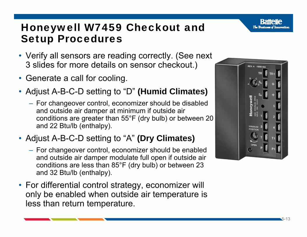
Honeywell W7459 Checkout and Setup Proceduresp• Verify all sensors are reading correctly. (See next
3 slides for more details on sensor checkout.)• Generate a call for cooling.• Adjust A-B-C-D setting to “D” (Humid Climates)
– For changeover control economizer should be disabled– For changeover control, economizer should be disabled and outside air damper at minimum if outside air conditions are greater than 55°F (dry bulb) or between 20 and 22 Btu/lb (enthalpy).
• Adjust A-B-C-D setting to “A” (Dry Climates)– For changeover control, economizer should be enabled
and outside air damper modulate full open if outside air diti l th 85°F (d b lb) b t 23conditions are less than 85°F (dry bulb) or between 23
and 32 Btu/lb (enthalpy).
• For differential control strategy, economizer will only be enabled when outside air temperature is
5-13
only be enabled when outside air temperature is less than return temperature.
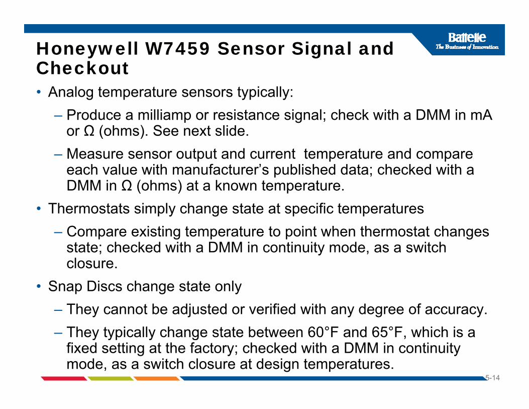
Honeywell W7459 Sensor Signal and Checkout• Analog temperature sensors typically:
– Produce a milliamp or resistance signal; check with a DMM in mA Ω ( h ) S t lidor Ω (ohms). See next slide.
– Measure sensor output and current temperature and compare each value with manufacturer’s published data; checked with a DMM in Ω (ohms) at a known temperature.
• Thermostats simply change state at specific temperaturesCompare existing temperature to point when thermostat changes– Compare existing temperature to point when thermostat changes state; checked with a DMM in continuity mode, as a switch closure.
S Di h t t l• Snap Discs change state only – They cannot be adjusted or verified with any degree of accuracy. – They typically change state between 60°F and 65°F which is a
5-14
– They typically change state between 60 F and 65 F, which is a fixed setting at the factory; checked with a DMM in continuity mode, as a switch closure at design temperatures.

Honeywell C7150 and C7046 Analog Temperature Sensor Checkout Chart (ohms/°F)p ( )
5-15
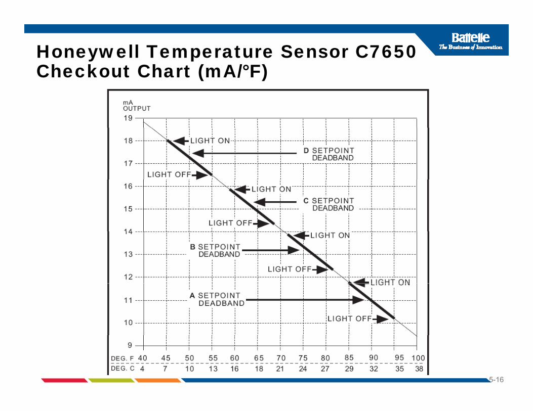
Honeywell Temperature Sensor C7650 Checkout Chart (mA/°F)Checkout Chart (mA/ F)
5-16

The W7459 is used in conjunction with a Honeywell actuator (M7415) and sensors to control outdoor andactuator (M7415) and sensors to control outdoor and return air dampers free cooling using outside air. It is designed to be installed directly on the actuator.
5-17

Honeywell W7459 Economizer Control
5-18

W7459 Enthalpy Economizer Control Settings = A,B,C, or Dg , , ,
5-19

Adjusting Minimum Damper Positionfor Honeywell W7459Ay
• Note: The W7459A uses inputs from mixed or discharge air temperature sensors.
• Minimum Position Adjustment - Minimum position potentiometer keeps outdoor air damper from closing completely during system operation to provide ventilation.
1. Disconnect mixed air sensor from terminals T and T1.2. Make sure either factory-installed jumper is in place across
terminals P and P1 or if remote damper positioner is required, that it is p p qwired according to Honeywell instructions and turned fully clockwise. See Figure on next slide.
3. Connect 24 Vac across terminals TR and TR1.4. Adjust potentiometer on face of W7459A with screwdriver to
desired minimum position.5. Note: Check actual percentage of OSA by utilizing % charts or
5-20
5. Note: Check actual percentage of OSA by utilizing % charts or formulas, discussed later.
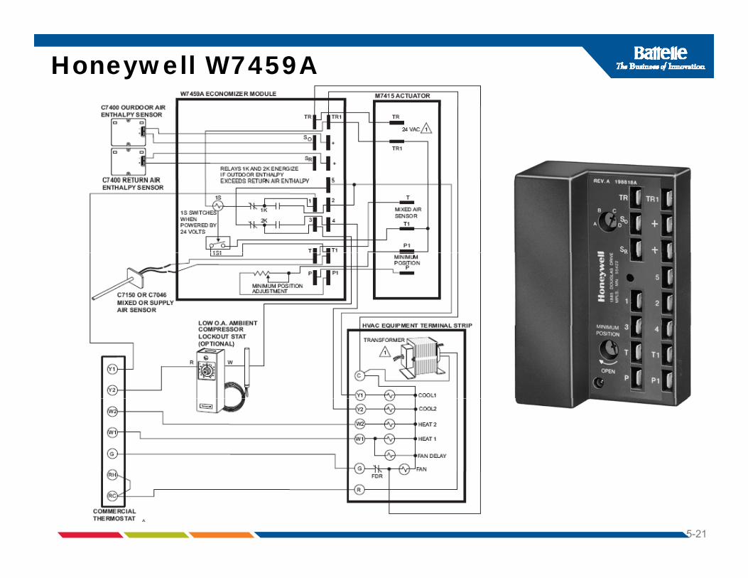
Honeywell W7459A
5-21
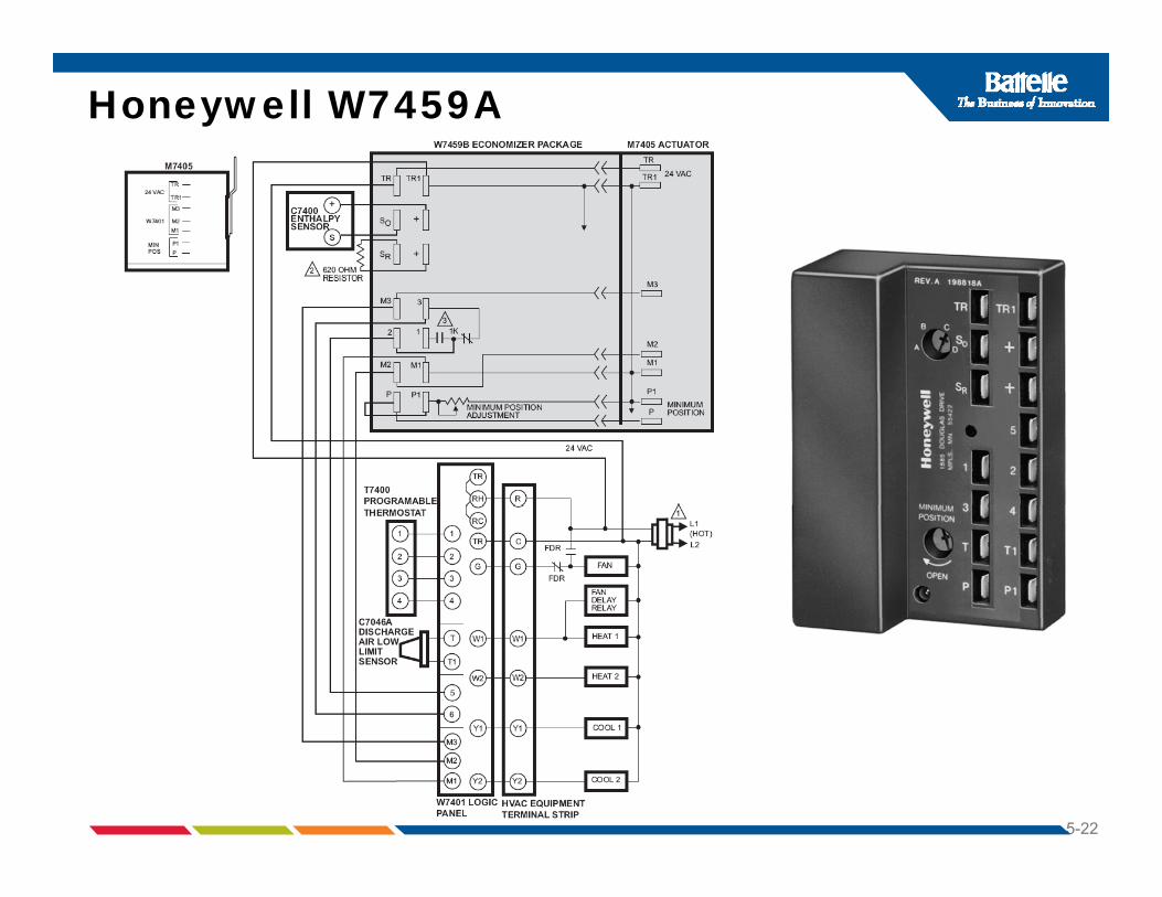
Honeywell W7459A
5-22

Adjusting Minimum Damper Positionfor Honeywell W7459By
• Note: The W7459B is designed for use with a W7401 Logic Panel or a Honeywell Legacy direct digital controller.y g y g
1. Make sure either the factory-installed jumper is in place across terminals P and P1 or if remote damper positioner is required, it is wired according to Honeywell instructions, and turned fullyis wired according to Honeywell instructions, and turned fully clockwise. See figure on next page.
2. Connect jumper across terminals M1 and M3.3. IMPORTANT: Do not contact or connect jumper to M2. If M2 is
jumpered to M1, the motor will not respond to the controller.4. Connect 24 Vac across terminals TR and TR1.5. Adjust potentiometer on face of W7459B with screwdriver to
desired minimum position.
5-23

Honeywell W7459B
5-24
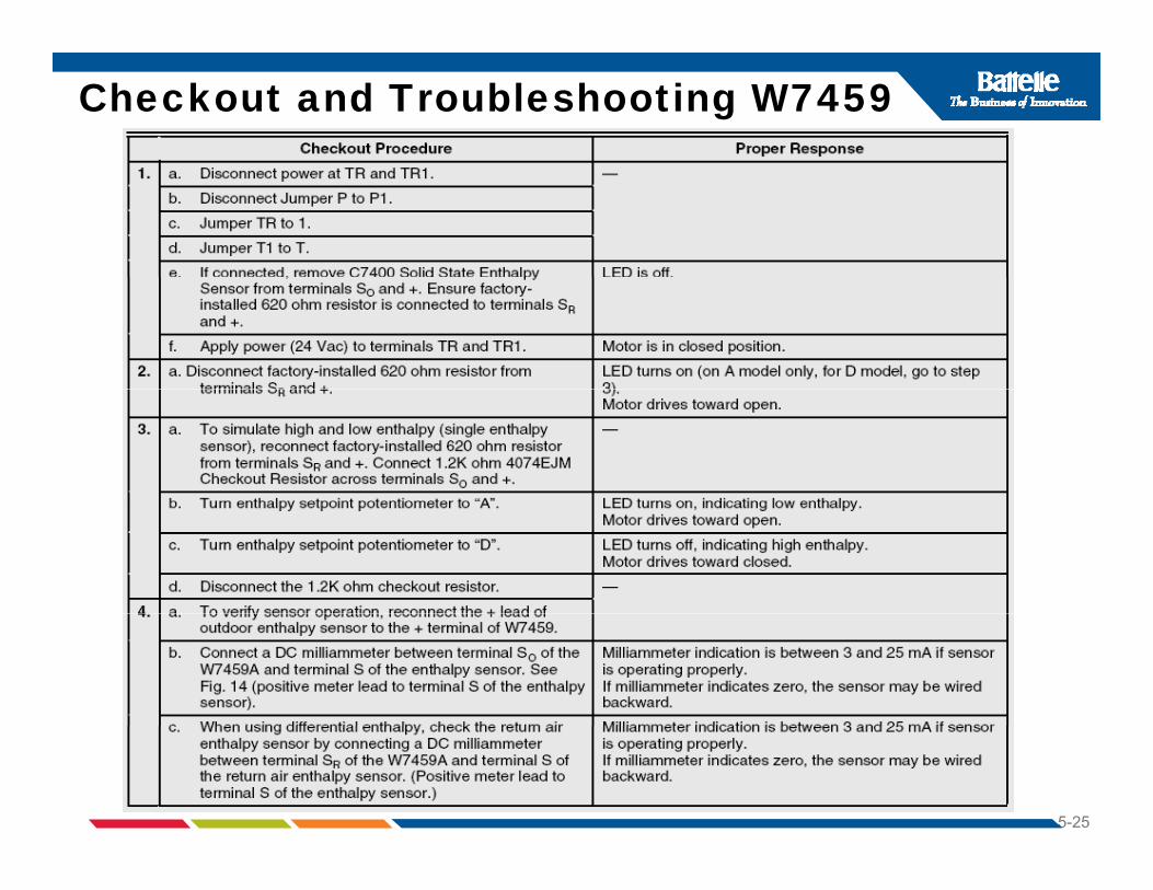
Checkout and Troubleshooting W7459
5-25

Exercise #5 (Provide Answers below on notes page)( p g )1. T or F When wired properly, the 1st stage of cooling must
go through the economizer controller circuit prior to energizing the compressor.
2. T or F When differential enthalpy is utilized, one sensor is in the outside air and one sensor is in the mixedin the outside air and one sensor is in the mixed air.
3. T or F When the enthalpy sensor is set at “D”, the unit is t t th i i l l f h id li tset to the minimum level for humid climates.
4. T or F To simulate high and low enthalpy settings, two resistors are needed: a 62O Ω and 1.2 kΩ.resistors are needed: a 62O Ω and 1.2 kΩ.
5. T or F A milliamp reading of 3 to 25 mA is the expected reading to check the differential enthalpy sensor.
5-26