HVAC Condenser
36
Condenser August 2012 Published by the International Institute of Ammonia Refrigeration as a service to its members and the Industrial Refrigeration Industry
description
HVAC Condenser
Transcript of HVAC Condenser

CondenserAugust 2012
Published by the International Institute of Ammonia Refrigeration as a service to its members and the Industrial Refrigeration Industry
98363_IIAR_AugCond.indd 1 8/8/12 2:50 PM

ii Condenser | August 2012 | A Publication of the International Institute of Ammonia Refrigeration
T E C N O L O G Y
SOLUTIONS
SUPPORT
INNOVATION
EXPERIENCE
RELIABILITY
HANSEN TECHNOLOGIES CORPORATION | 800.426.7 368 | [email protected] | WWW.HANTECH.COM
An Employee Owned Company
EVAPCO, Inc. • 5151 Allendale Lane • Taneytown, MD 21787Phone: 410-756-2600 • Fax: 410-756-6450
Visit EVAPCO's Website at http://www.evapco.com
Evaporative Condensers
Ceiling Hung Evaporators
Penthouse Evaporators
Custom Freezing Capabilities
Hygienic Air Handling Units
Desiccant Air Handling Systems
Liquid Recirculator Packages
ASME Pressure Vessels
Cooling Towers
Closed Circuit Coolers
Water Treatment Systems
InnovativeProduct SolutionsAvailable Today!
Contact Your Local EVAPCO Sales Representative
for More Information
C R I T I C A L P R O C E S S A I R S Y S T E M
™
IIAR Ad Aug. '12:Evapco 7/16/12 5:35 PM Page 1
98363_IIAR_AugCond.indd 2 8/7/12 10:20 AM

Condenser | August 2012 | A Publication of the International Institute of Ammonia Refrigeration 1
T E C N O L O G Y
SOLUTIONS
SUPPORT
INNOVATION
EXPERIENCE
RELIABILITY
HANSEN TECHNOLOGIES CORPORATION | 800.426.7 368 | [email protected] | WWW.HANTECH.COM
An Employee Owned Company
EVAPCO, Inc. • 5151 Allendale Lane • Taneytown, MD 21787Phone: 410-756-2600 • Fax: 410-756-6450
Visit EVAPCO's Website at http://www.evapco.com
Evaporative Condensers
Ceiling Hung Evaporators
Penthouse Evaporators
Custom Freezing Capabilities
Hygienic Air Handling Units
Desiccant Air Handling Systems
Liquid Recirculator Packages
ASME Pressure Vessels
Cooling Towers
Closed Circuit Coolers
Water Treatment Systems
InnovativeProduct SolutionsAvailable Today!
Contact Your Local EVAPCO Sales Representative
for More Information
C R I T I C A L P R O C E S S A I R S Y S T E M
™
IIAR Ad Aug. '12:Evapco 7/16/12 5:35 PM Page 1
98363_IIAR_AugCond.indd 1 8/7/12 10:20 AM
2 Condenser | August 2012 | A Publication of the International Institute of Ammonia Refrigeration
International Institute of Ammonia Refrigeration
1001 North Fairfax Street, Suite 503
Alexandria, VA 22314 | www.iiar.org
Phone: 703-312-4200 | Fax: 703-312-0065
Condenser Staff
Publisher | Bruce Badger | [email protected]
Editor-In-Chief | Andrea Fischer | [email protected]
Layout & Design | Laura Dugan
CONTENTS
3 Chairman’s Message
4 Choosing the Right Emergency Eyewash and Shower Equipment
7 NDT Methods for the Ammonia Refrigeration Industry
8 IIAR Code Advocacy Update
11 IIAR 2013 Industrial Refrigeration Conference & Exhibition
12 IIAR Government Relations Update
14 IIAR Seeks Associate Technical Director
15 Applications of the Ammonia Low Pressure Receiver to Small Commercial Systems
WHY SETTLE FOR LESS? GET THE
BESTPROTECTION!
Protect Your System.
50% less oil carry over to low side.Less oil in system coils.Low pour point.Cleaner system.Better heat transfer.Less oil consumption.
Protect TheEnvironment.
Non toxic.
Non hazardous.
Non carcinogenic.
Authorized by the USDAand NSF for use infederally inspected meatand poultry plants.
Protect Compressors,Pumps & Gear Boxes.
Oxidatively stable up to eight timeslonger than conventional oils.
Non carbon or sludge forming.
Reduced compressor wear.
Maximum bearing protection.
Less energy consumption.
CAMCO 717 AmmoniaRefrigeration Oils SaveTime and Money.
Protect your product and personnel, affordably!Features• Detect concentrations of ammonia as low as 25 PPM. Sensitivity control
adjustable from 25 to 800 PPM (1000 PPM for LBW-420).• Dependable, long-life, solid state circuitry• Contacts for operating auxiliary equipment• Contacts for common industry alarm systems• NEMA 4X, UL-listed CSA, IEC, IP66 enclosure• One year warranty on workmanship from time of sale• Service switch for servicing without alarming
Typical ApplicationsIndustrial coolers and freezers, compressor rooms, control rooms,loading docks, storage tank areas.
Available Options• Remote sensor with box and cable• High-low temperature sensor (LBW-420 only)• ABS washdown/utility tube• Battery back-up• Remote alarm light & horn unit
1441 Rice Street • St. Paul, Minnesota 55117-3899 Office: 651-487-8844 • Fax: 651-487-8857E-Mail: [email protected] product info at www.coolairinc.comMade in the USA
Model LBW-50 Model LBW-420
Integrate seamlessly with industry alarm systems
Ammonia Leak Detectorsfrom the leading supplier of ammonia refrigeration systems and controls
Early warning to your employees: Quick response toleaks, 24 hours a day. Meets OSHA requirements.Saves money: Possible 5 to 15% reduction in annualinsurance premiums as well as additional insurance coverage.
Specializing in Synthetic and Semi-SyntheticLubricants for Refrigeration,Food Processingand Industrial ApplicationsCorporate Office: 1441 Rice Street • St. Paul, MN 55117-3899Tel: 651-489-8828 • Fax: 651-487-8857 • Toll-free: 1-877-205-1234Mike L. Worms • email: [email protected]
16 Ammonia Refrigeration Foundation Update
20 Global View
26 Committee Update
31 IIAR Membership
32 From the Technical Director
98363_IIAR_AugCond.indd 2 8/8/12 2:51 PM

Condenser | August 2012 | A Publication of the International Institute of Ammonia Refrigeration 3
To continue the success initiated by these meetings, Bruce worked with the International Committee to implement a new membership outreach program to meet the needs of potential members in Article V (developing) countries and the BRIC countries (Brazil, Russia, India and China).
Under his leadership, our organization has successfully delivered the message that IIAR is an effective advocate for the use of natural refrigerants in industrial refrigeration applications, and is the most comprehensive source of technical information on the topic, both in the U.S. and around the world.
While international outreach and a focus on meeting IIAR’s government advocacy and code development goals have long been a central part of Bruce’s tenure, he has also worked to position the organization to grow from an operational level. In a difficult global economy, that has contributed to dwindling membership numbers and uncertain financial futures for many associations, the IIAR was able to purchase the new Headquarters Office in Alexandria, Virginia and increase membership to record levels.
Bruce will leave this organization in a great position when he retires next June. However, for now it is “business as usual” for him, the Executive Committee, Board of Director, Committees and Headquarters Staff as we work to execute the important projects and activities to meet the goals outlined the Strategic Plan and Budget for the 2012-2013 Fiscal Year.
As Board Chairman, I would like to thank all of the members currently volunteering your time and expertise to serve the IIAR and encourage all of you to consider volunteering in the future.
Finally, I challenge all IIAR members to get involved in the search for our next President. Bruce’s announcement means the IIAR is now actively seeking a new President willing to continue to advance the organization’s mission and leadership throughout the global industrial refrigeration industry and address the future needs of our members.
The IIAR Executive Committee believes the ideal candidate should be an individual with an industrial refrigeration background, management and leadership skills, and a willingness to inspire the IIAR membership to find innovative solutions to the many challenges this industry faces in North America, Europe and the entire International community. This individual will be in the unique position of managing the activities of a fast-moving technical organization with many exciting initiatives in place to fulfill its mission globally, provide essential member benefits and poised for future growth.
Whether you are considering the position yourself, or you would like to recommend a potential successor, please send any communication directly to me via email at [email protected] or contact me at (410) 756-2600.
Chairman’s Message
By Joe Mandato
IIAR is a group of professionals representing End-users, Engineers, Contractors, Manufacturers and Educational Institutions who are dedicated to the advancement of the safe use of natural
refrigerants in the refrigeration industry. I am pleased to report that this dedication is paying off more than ever as IIAR has been able to complete many important projects, form successful advocacy initiatives and grow because of the increased involvement by our members. As a result, IIAR is recognized as the preeminent source of technical standards and educational tools developed and distributed to improve the safety and efficiency of refrigeration systems using ammonia and other natural refrigerants throughout the world.
An example of this was the 2012 Industrial Refrigeration Conference which saw one of the best turnouts in IIAR’s history, following several years of increasing attendance levels. The organization’s influence and reputation is growing rapidly around the world thanks to a renewed focus on global outreach.
I am pleased to report the advocacy efforts of the organization will be strengthening in the near future as a result of the Board of Director’s approval in June to establish a Government Relations Committee. I want to thank Mark Stencel for volunteering to serve as Chairman of this new committee, whose purpose will be to support the work of Lowell Randel, IIAR Government Relations Director, and inform IIAR members of changes and trends in government activities.
IIAR’s success in recent years is due in large part to the hard work of the volunteer members who serve on the many working Committees and Task Forces, the Executive Committee, Board of Directors and our current President, Bruce Badger.
During the IIAR Board of Directors meeting in June, Bruce announced his plans to retire as President at the end of this fiscal year, June 30, 2013.
Since he became IIAR’s President in December, 2007, Bruce has worked diligently to improve the financial stability of the organization while building and managing a professional headquarters staff focused on serving our members. He has also been instrumental in the growth of IIAR’s global outreach program.
Bruce has worked closely with Paul Bishop–Chairman of the International Committee and the active committee members to improve the global presence of the organization. Together, with IIAR Board Members, they have traveled to developing countries like Russia, China, Saudi Arabia, Macedonia, South Africa, Brazil and many other Latin American countries. He has also been instrumental in building strong relationships with industry related associations in both China and India, establishing partnerships that will support the expansion of the IIAR mission in those two countries for years to come.
International Institute of Ammonia Refrigeration
1001 North Fairfax Street, Suite 503
Alexandria, VA 22314 | www.iiar.org
Phone: 703-312-4200 | Fax: 703-312-0065
Condenser Staff
Publisher | Bruce Badger | [email protected]
Editor-In-Chief | Andrea Fischer | [email protected]
Layout & Design | Laura Dugan
98363_IIAR_AugCond.indd 3 8/7/12 10:20 AM
4 Condenser | August 2012 | A Publication of the International Institute of Ammonia Refrigeration
C
M
Y
CM
MY
CY
CMY
K
IS04449-VilterHotDogAd_TheCondsr-FIN.pdf 1 3/30/12 3:27 PM
Addressing that gray area can be a challenge for facilities without a formal strategy for positioning eyewash and shower equipment. Installing permanent eyewash and shower stations in every part of a facility that has even a small chance that an exposure to ammonia might occur can be prohibitively expensive. But focusing only on the machine room to the exclusion of all other, even unlikely, hazardous areas can be a potentially dangerous response.
The answer, said Jordan, is to establish a clear method to determine where to install different kinds of emergency eyewash and shower equipment according to the risk and likelihood of exposure to ammonia. Then, he said, that method should be applied to every area of a facility where ammonia is present.
Jordan worked on a project to develop just such a strategy for a large IIAR member and end-user company. “We worked closely to develop a philosophy and method to answer the questions surrounding where to put eyewash and shower stations, and how to determine what kinds of eyewash and shower stations are most effective in what kinds of areas and use cases,” said Jordan.
That philosophy and method can be used to develop a plan for installing a comprehensive eyewash and safety shower system at almost any facility because it employs an easy to apply evaluation using a risk ranking method, said Jordan.
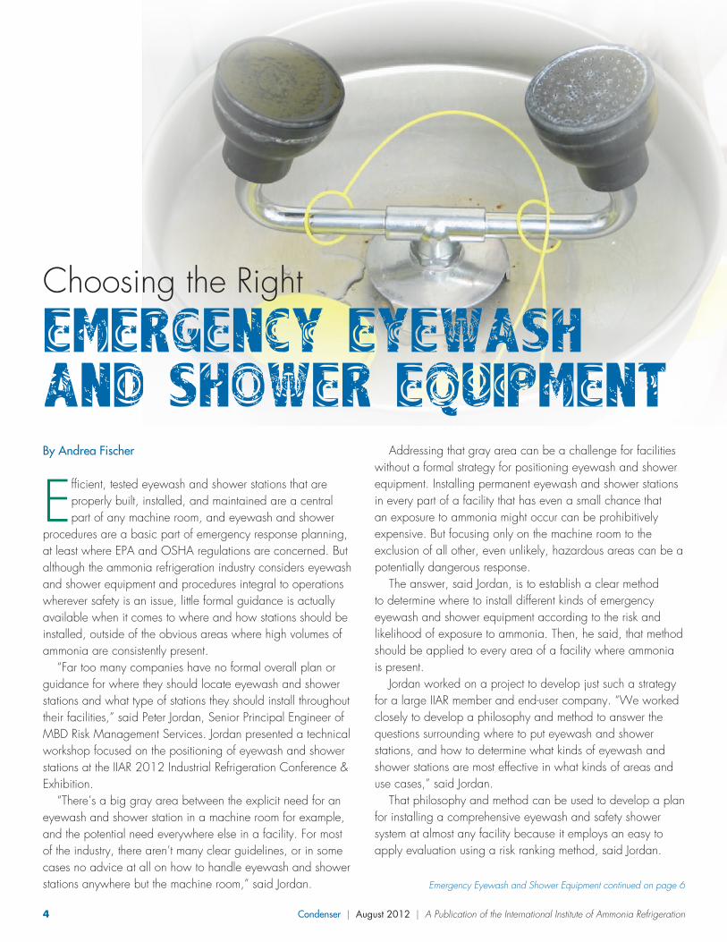
By Andrea Fischer
Efficient, tested eyewash and shower stations that are properly built, installed, and maintained are a central part of any machine room, and eyewash and shower
procedures are a basic part of emergency response planning, at least where EPA and OSHA regulations are concerned. But although the ammonia refrigeration industry considers eyewash and shower equipment and procedures integral to operations wherever safety is an issue, little formal guidance is actually available when it comes to where and how stations should be installed, outside of the obvious areas where high volumes of ammonia are consistently present.
“Far too many companies have no formal overall plan or guidance for where they should locate eyewash and shower stations and what type of stations they should install throughout their facilities,” said Peter Jordan, Senior Principal Engineer of MBD Risk Management Services. Jordan presented a technical workshop focused on the positioning of eyewash and shower stations at the IIAR 2012 Industrial Refrigeration Conference & Exhibition.
“There’s a big gray area between the explicit need for an eyewash and shower station in a machine room for example, and the potential need everywhere else in a facility. For most of the industry, there aren’t many clear guidelines, or in some cases no advice at all on how to handle eyewash and shower stations anywhere but the machine room,” said Jordan. Emergency Eyewash and Shower Equipment continued on page 6
Choosing the Right
EMERGENCY EYEWASH AND SHOWER EQUIPMENT
98363_IIAR_AugCond.indd 4 8/7/12 10:20 AM

Condenser | August 2012 | A Publication of the International Institute of Ammonia Refrigeration 5
C
M
Y
CM
MY
CY
CMY
K
IS04449-VilterHotDogAd_TheCondsr-FIN.pdf 1 3/30/12 3:27 PM
98363_IIAR_AugCond.indd 5 8/7/12 10:20 AM

6 Condenser | August 2012 | A Publication of the International Institute of Ammonia Refrigeration
The objective is to evaluate risk and likelihood of exposure to ammonia and respond in an appropriate measure.
For example, a large volume of ammonia in one area where maintenance is routinely performed would rank high on a “likelihood and severity of exposure” risk matrix and would require a permanent eyewash and shower station. A smaller volume of ammonia where maintenance is only rarely performed, for example on the roof of a facility, might carry a low exposure risk and would only require a temporary eyewash and shower station to constitute an adequate safety response. “The questions to answer are, where can you go permanent and where can you go temporary, and what are your options when it comes to temporary stations?” said Jordan.
The first step in developing the risk matrix Jordan uses to determine appropriate eyewash and shower equipment resources at a facility was to take a look at all available regulatory guidance.
According to ANSI, IIAR-2-2008 requirements, an emergency unit must be installed “external to each machinery room readily accessible via an exit.” Additionally, units inside each machinery room must be positioned “such that no unit is further than 10 seconds or 55 feet [16.8 m] from a hazard.”
The IIAR-2 guidance is clear, but does not address any safety scenarios beyond the machine room, such as how to provide eyewash and safety shower capabilities when necessary in other cases, said Jordan, who added that he next examined OSHA requirements.
According to OSHA requirement 29 CFR 1910.151(c): “Where the eyes or body of any person may be exposed to injurious corrosive materials, suitable facilities for quick drenching or flushing of the eyes and body shall be provided within the work area for immediate emergency use.”
The OSHA language brings up several considerations, said Jordan, including the idea that even if a facility has emergency eyewash and shower equipment available at fixed locations, and safety plans that make use of personal protective equipment, an eyewash and shower safety plan should still make provisions for a “last resort,” or a ready method of eyewash and safety shower capabilities. “What this says to me is that we can’t just rely on other safety methods,” said Jordan. “We still have to have a backup when it comes to eyewash and shower capability.”
Perhaps some of the most specific guidance concerning eyewash and shower program strategies comes from concerns raised during facility inspections conducted by EPA region 7 officials, said Jordan.
Companies developing an eyewash and safety shower philosophy can look to four specific citations issued as a result of these inspections to learn how to watch out for weaknesses
that regulators are looking for in eyewash and safety shower programs.
According to Jordan, EPA’s four citations addressed: the absence of units in all areas where potential eye injuries could occur; cases where inspection records were not available, and, or inspections were not performed; units that discharged rusty water; and units that didn’t comply with ANSI design and operation standards.
The last citation in that list is an especially important item to pay attention to because any eyewash and safety shower plan should meet all the provisions set out by ANSI/ISEA Z358 1-2009, the ANSI standard that provides minimum requirements for emergency eyewash and shower equipment.
This standard addresses the performance, use, installation, test procedures, maintenance and training related to permanent eyewash and shower stations and identifies a number of choices for temporary eyewash and shower stations. “This ANSI standard is really the bible for eyewash and safety shower,” said Jordan. “Any safety plan should begin and end with this standard.”
The first three descriptions of safety options for eyewash and shower units laid out by the ANSI standard address permanent units and include definitions of emergency showers, eyewash stations and permanent eye/face wash equipment.
According to ANSI, emergency showers should be designed to deliver flushing fluid in sufficient volume (20 gpm, 15 minutes) to cascade over the entire body. Emergency showers should be placed in accessible locations, defined as taking less than ten seconds to reach from the potential incident area. Appendix B in the standard indicates that the average person travels a distance of approximately 55 feet in 10 seconds when walking at a normal pace. The showers should be located on the same level as the hazard, and in a place where the path of travel is free of obstructions that may inhibit their immediate use. Finally, the showers should deliver tepid flushing fluid at temperatures between 60°F to 100°F.
The second permanent safety option, an eyewash station, is any device defined by ANSI as capable of irrigating and flushing both eyes simultaneously. Eyewash stations should be capable of delivering 0.4 gpm of fluid for 15 minutes and
Emergency Eyewash and Shower Equipment continued from page 4
Emergency Eyewash and Shower Equipment continued on page 22
Permanent Eyewash Station, Emergency Shower
98363_IIAR_AugCond.indd 6 8/7/12 10:20 AM

Condenser | August 2012 | A Publication of the International Institute of Ammonia Refrigeration 7
NDT Methods continued on page 17
Figure 1
By Jim Kovarik, Gamma Graphics Services
In other industries, insulation is installed to protect people from touching hot process piping and getting burned; or to keep heat in the pipe to assist in lowering the viscosity
of the process fluid thereby facilitating flow. If water comes in contact with hot piping, it will evaporate quickly or boil-off immediately, and therefore, corrosion under insulation is not a great concern. The ammonia refrigeration industry is markedly different from other industries. In the ammonia refrigeration industry, insulation is installed on piping to prevent the pipe from absorbing heat. Because refrigeration piping is generally cold, water vapor will condense on it if given an opportunity. Any water that condenses or comes in contact with the pipe through some other means will not readily evaporate or boil-off, but becomes trapped in the insulation. Three things necessary for corrosion under insulation (CUI) are: water, unprotected metal, and oxygen. If the temperature of the pipe is ever above 32°F, then the conditions are ripe for corrosion to occur. If the pipe experiences thermal cycling (freezing then thawing, then freezing again), the rate of corrosion actually increases. This is due to the fact that ice expands and will flake-off larger sections of metal exposing bare metal underneath. When the ice thaws, the water will flow into the newly created fissures left behind by the ice and begin to corrode the fresh metal surfaces. When the pipe freezes again, the water will form ice which flakes even more metal away from the rest of the pipe and the process continues until the pipe eventually fails.
So, how can we find out if CUI is occurring? Non-Destructive Testing (NDT) is comprised of many different methods and techniques that will not harm the object being
tested. Of the dozens of nondestructive inspection methods available, only a few are applicable to identify corroded areas on insulated piping. Most of these involve some removal of insulation in order to inspect the pipe.
The most common NDT method is ultrasonic thickness testing (UTT). The basic physics of ultrasonic thickness testing involves the fact that sound travels at very specific velocities in different materials (Fig. 1). Sound travels much slower in ice than in steel. Sound travels very slowly in air – that is why you can see a lighting strike before you hear the thunder. The ultrasonic instrument measures the time it takes sound to enter a material (in this case the pipe), bounce off the inside wall of the pipe and return to the transducer. The time it takes to
make the round trip is multiplied by the velocity of the sound in the material (steel), and the result is the total distance that the sound traveled. In other words, the ultrasonic instrument converts time into distance. The speed of sound in ice at 0° C is 1402 M/s and the speed of sound in steel is more than four times as fast at 5790 M/s. Because sound travels so poorly in air, a couplant, or medium is used to “couple” the transducer to the pipe. This couplant is compressed so that a very thin layer is present between the transducer and the pipe which facilitates sound transmission, but does not change the thickness measurement. In most cases, the couplant is a water-based gel. UTT on ammonia piping and vessels is accomplished by removing a plug in the insulation and placing a transducer on the pipe through the hole. Unfortunately, many NDT technicians perform UTT on piping and vessels at refineries or utility
plants where the pipe and vessels are at or above ambient temperatures. In cold applications where the temperature
NDT Methods for the Ammonia Refrigeration Industry
NDT METHODS FOR THE AMMONIA REFRIGERATION INDUSTRY
In other industries, insulation is installed to protect people from touching hot process piping and getting
burned; or to keep heat in the pipe to assist in lowering the viscosity of the process fluid thereby
facilitating flow. If water comes in contact with hot piping, it will evaporate quickly or boil-off
immediately, and therefore, corrosion under insulation is not a great concern. The ammonia
refrigeration industry is markedly different from other industries. In the ammonia refrigeration industry,
insulation is installed on piping to prevent the pipe from absorbing heat. Because refrigeration piping
is generally cold, water vapor will condense on it if given an opportunity. Any water that condenses or
comes in contact with the pipe through some other means will not readily evaporate or boil-off, but
becomes trapped in the insulation. Three things necessary for corrosion under insulation (CUI) are:
water, unprotected metal, and oxygen. If the temperature of the pipe is ever above 32°F, then the
conditions are ripe for corrosion to occur. If the pipe experiences thermal cycling (freezing then
thawing, then freezing again), the rate of corrosion actually increases. This is due to the fact that ice
expands and will flake-off larger sections of metal exposing bare metal underneath. When the ice
thaws, the water will flow into the newly created fissures left behind by the ice and begin to corrode the
fresh metal surfaces. When the pipe freezes again, the water will form ice which flakes even more
metal away from the rest of the pipe and the process continues until the pipe eventually fails.
So, how can we find out if CUI is occurring? Non-Destructive Testing (NDT) is comprised of many
different methods and techniques that will not harm the
object being tested. Of the dozens of nondestructive
inspection methods available, only a few are applicable to
identify corroded areas on insulated piping. Most of these
involve some removal of insulation in order to inspect the
pipe.
The most common NDT method is ultrasonic thickness
testing (UTT). The basic physics of ultrasonic thickness
testing involves the fact that sound travels at very specific
velocities in different materials (Fig. 1). Sound travels much
slower in ice than in steel. Sound travels very slowly in air –
that is why you can see a lighting strike before you hear the
thunder. The ultrasonic instrument measures the time it takes
sound to enter a material (in this case the pipe), bounce off
the inside wall of the pipe and return to the transducer. The
time it takes to make the round trip is multiplied by the
velocity of the sound in the material (steel), and the result is
the total distance that the sound traveled. In other words, the
ultrasonic instrument converts time into distance. The speed
of sound in ice at 0° C is 1402 M/s and the speed of sound
in steel is more than four times as fast at 5790 M/s. Because
sound travels so poorly in air, a couplant, or medium is used
to “couple” the transducer to the pipe. This couplant is
compressed so that a very thin layer is present between the
transducer and the pipe which facilitates sound transmission,
but does not change the thickness measurement. In most cases, the couplant is a water-based gel. UTT
on ammonia piping and vessels is accomplished by removing a plug in the insulation and placing a
Figure 1
98363_IIAR_AugCond.indd 7 8/7/12 10:20 AM

8 Condenser | August 2012 | A Publication of the International Institute of Ammonia Refrigeration
By Jeffrey M. Shapiro, P.E., FSFPE
Refrigerant Leak Detection Systems – Do What?
There are many devices on the market that can detect and respond to a refrigerant leak, but the International, Uniform, NFPA, ASHRAE and IIAR codes and standards provide limited guidance with respect to detector location, installation and equipment requirements or the extent of alarm notification that must be provided when a leak is detected. In a previous Condenser column published in 2009, I wrote on the topic of leak detection, focusing on requirements for power supply, electrical supervision of circuits, reporting of alarms and whether third party listing of equipment is needed. This column looks at the topic from a different perspective, specifically, requirements for locating detection devices and required notification signals for alarm conditions.
Let’s start with the detectors themselves. It’s important to begin by pointing out that model codes and standards don’t limit the requirements for leak detection to refrigeration systems that use ammonia.
Once a machinery room is required, even for Safety Group A1 refrigerants, leak detection in the machinery room is mandatory. Leak detection is actually more important for Safety Group A1 refrigerants than for ammonia because ammonia’s self-alarming odor will force an evacuation response by occupants at concentrations well below those that trigger acute health or fire safety concerns. In contrast, a leak of an odorless Safety Group A1 refrigerant can reach dangerous concentrations without any indication of the impending danger to occupants or emergency responders. That danger can be compounded if the refrigerant comes into contact with an open flame device, which can lead to extremely dangerous and odorless combustion byproducts.
Although the science of refrigerant leak detection and the equipment used are well-developed, the codes and standards that regulate leak detection systems largely defer to the judgment of design professionals. The lack of regulatory constraint comes with pros and cons. On the plus side, codes and standards, as they are currently written, are flexible enough to accommodate variations in field erected systems. On the minus side, the lack of clear benchmarks for determining code compliance can lead to job delays and cost overruns when designers and enforcers interpret the code differently.
As an example, look at the requirements for placement of leak detection devices. ASHRAE 15, Section 8.11.2.1 states “Each refrigerating machinery room shall contain a detector, located in an area where refrigerant from a leak will concentrate.” Uniform Mechanical Code (UMC) Section 1107.4 contains similar text “Machinery rooms shall be provided with approved refrigerant-vapor detectors sensing where refrigerant from a leak is likely to concentrate.” If you read these two sections quickly, they might appear to be the same, but look closely. ASHRAE 15 requires “a detector” and the UMC requires “approved refrigerant vapor detectors.”
A subtle but important difference is that the UMC text includes the word “approved,” which provides clear authority to the code official to accept or reject the type of detection device that will be permitted. Might it be possible for the code official to require that detection devices be listed by a third-party testing laboratory? There is nothing to prohibit the code official from applying the code in that way, and given the broad definition of the word “approved” and the lack of guidance in the code as to what the code official should contemplate in determining approval, the answer is yes (albeit no such devices are currently available).
Look at the code text again, ASHRAE 15 uses the singular word “detector;” whereas, the UMC uses the plural “detectors.” Should this be taken to imply that more than one detector must be provided? In the case of ammonia, the answer is yes, but for a different reason. IIAR-2 Section 13-2 requires “Each refrigerating machinery room shall contain at least two refrigerant detectors.” This text leaves open the question of whether more than two detectors might be needed. Some may argue that a large room might need additional detectors, and because neither codes nor standards specify linear distance or area limits for detectors there is no conclusively right or wrong answer. For now, the determination is largely left to device manufacturers and system design engineers, but lacking third-party testing or listing of detectors, the current system relies on a code official trusting design recommendations. This can be a problem considering that code officials are more accustomed to dealing with smoke and carbon monoxide detectors, which require third-party listings and are highly regulated with respect to permissible spacing and location.
IIAR Code Advocacy Update
Code Update continued on page 10
98363_IIAR_AugCond.indd 8 8/7/12 10:20 AM

Condenser | August 2012 | A Publication of the International Institute of Ammonia Refrigeration 9
98363_IIAR_AugCond.indd 9 8/7/12 10:20 AM

10 Condenser | August 2012 | A Publication of the International Institute of Ammonia Refrigeration
The potential for conflict over differing code interpretations related to leak detector location is clear. Additional requirements in the International Mechanical Code; NFPA 72 National Fire Alarm Code; model fire codes don’t make things better. Then, for ammonia refrigeration, there is one more very important consideration. The exceptions that allow storage and processing areas to contain ammonia refrigeration equipment provided in ASHRAE 15 and the model mechanical codes are all conditional, based on leak detection being provided. These exceptions include the following text:
ASHRAE 15, Section 7.2.2 (4) “Refrigerant detectors are installed with the sensing location and alarm level as required in refrigerating machinery rooms in accordance with Section 8.11.2.1.”
UMC Section 1105.3.1 “The refrigerated room or space is equipped with a refrigerant vapor detection and alarm system complying with Section 1121.0.”
IMC Section 1104.2.2 (4) “Refrigerant detectors are installed as required for machinery rooms in accordance with Section 1105.3.”
All of these sections point back to the detection requirements for machinery rooms discussed above. So, questions about the minimum required number and spacing of ammonia detectors extend beyond machinery rooms to include refrigerated storage and processing areas, which are often larger and may have complex floor plans.
A second example of code text that may lead to conflicting interpretations involves the alarm signal that leak detectors are required to initiate. As was the case for locating refrigerant detectors, codes and standards provide little guidance with respect to what type of alarm signal must be provided:
ASHRAE 15, Section 8.11.2.1 “Each refrigerating machinery room shall contain a detector…that actuates an alarm…at a value not greater than the corresponding TLV-TWA (or toxicity measure consistent therewith). The alarm shall annunciate visual and audible alarms inside the refrigerating machinery room and outside each entrance to the refrigerating machinery room…Alarms set at other levels (such as IDLH) and automatic reset alarms are permitted in addition to those required by this section…” (See also Informative Appendix F, which includes the statement “The refrigerant detector…triggers alarms inside and outside the refrigerating machinery room; signage warns refrigeration technicians and bystanders not to enter when the alarm has activated.”
UMC, Section 1107.4 “Machinery rooms shall be provided with approved refrigerant-vapor detectors…
Code Update continued from page 8 that will activate visual and audible alarms inside the refrigerating machinery room, outside each entrance to the refrigerating machinery room and…Alarms shall be activated at a value not exceeding one-half the immediately dangerous to life or health (IDLH), or measurement consistent therewith; the PEL, or measurement consistent therewith; or 25 percent of the LFL, whichever is less.” (See also Section 1121)
IFC Section 606.8 “Machinery rooms shall contain a refrigerant detector with an audible and visual alarm…The alarm shall be actuated at a value not greater than the corresponding TLV-TWA values shown in the International Mechanical Code for the refrigerant classification.”
IIAR-2 Section 13.2.3.1 “One detector shall be utilized to activate an alarm…at a value not greater than the corresponding TLV-TWA;” and Section 13.2.1.2 “The detectors shall activate visual and audible alarms inside the refrigerating machinery room and outside each entrance to the refrigerating machinery room.”
On the topic of alarm initiation, the codes and standards are prescriptive and are in general agreement that an alarm signal should be initiated at the TLV-TWA concentration (the text “or consistent therewith” in the UMC gets you there), which is 25 ppm for ammonia. The TLV-TWA value represents the concentration of refrigerant in air to which nearly all workers could be repeatedly exposed for an 8-hour workday and a 40-hour workweek without adverse effects. This is not truly a hazardous concentration, but instead a warning that is given to signal the potential for a hazardous condition to develop.
On the topic of alarm notification devices, things aren’t quite so good. All of the documents cited above require audible and visual alarms, and ASHRAE 15, the UMC and IIAR-2 all specify that alarm devices must be provided inside the machinery room and outside each entrance to the machinery room. This implies a single audible and visual device at each location mentioned, but the purpose of the alarm signal is not specified.
Some interpret the intent of the alarm signal to be notifying a responsible individual, but jurisdictions have reportedly interpreted the requirements as mandating an occupant evacuation alarm system, complete with visual devices that comply with the Americans with Disabilities Act (ADA), just as is required for fire alarm systems. In addition, some jurisdictions have reportedly asked for the TLV-TWA alarm to notify the fire department as a basis for initiating an emergency response. All of this is further complicated by the
Code Update continued on page 25
98363_IIAR_AugCond.indd 10 8/7/12 10:21 AM

Condenser | August 2012 | A Publication of the International Institute of Ammonia Refrigeration 11
IIAR2013
Colorado Springs, ColoradoMarch 17–20, 2013
98363_IIAR_AugCond.indd 11 8/7/12 10:21 AM

12 Condenser | August 2012 | A Publication of the International Institute of Ammonia Refrigeration
and ammonia safety. Representatives from the Alliance will participate in a workshop at the upcoming Voluntary Protection Plan Participants Association’s meeting in August 2012. And, in October representatives from the Alliance will participate in a program at in the National Safety Council Congress and Expo to highlight the activities of the Alliance. These events represent good opportunities to share the experiences of the Alliance and discuss ways to improve ammonia safety.
Participation in the Alliance also affords IIAR the opportunity to gain access to information about evolving OSHA programs. For example, OSHA is moving forward with the implementation of the Globally Harmonized System of Chemical Classification and Labeling (GHS). The new system includes changes to safety data sheets and labeling requirements for chemicals. It also includes employee training requirements. OSHA hosted a GHS Roundtable for Alliance participants on July 18, 2012 where participants learned more about GHS and what companies need to know about being in compliance. Also through the Alliance, IIAR members were given the opportunity to participate in a webinar hosted by OSHA and the Society of Chemical Hazard Communication Alliance outlining the revised hazard communication standards and what to expect in the workplace.
The Alliance has provided opportunities to train and educate OSHA staff about ammonia refrigeration and the cold chain industry. Given the decentralized nature of OSHA, it is important that educational opportunities are available to OSHA personnel to better understand the ammonia refrigeration industry. Members have had varying experiences with OSHA inspectors and their knowledge about industrial refrigeration. In some cases, OSHA inspectors without experience in industrial refrigeration apply standards from other industries such as the petroleum industry. These education and training opportunities can help address this issue and build a better understanding of the industrial refrigeration industry and IIAR resources so that appropriate standards are applied. OSHA has appreciated these opportunities and recently highlighted a program offered through the GCCA/IIAR Alliance in OSHA’s Alliance Quarterly publication.
The Alliance has also produced a series of posters focused on ammonia safety, the latest of which addresses the National Emphasis Program for Chemical Facilities. The NEP poster is designed to increase awareness of and preparedness for, the NEP.
by Lowell Randell, IIAR Government Relations Director
IIAR Takes Two-Pronged Approach to Engage with OSHA
With the initiation of the National Emphasis Program for Chemical Facilities (NEP) in 2009 and the nationalization of the program in late 2011, OSHA enforcement activity in the ammonia refrigeration industry has been intensifying. At least twenty five percent of all NEP inspections are occurring in ammonia refrigeration facilities and are impacting IIAR members across the United States. In response to evolving OSHA policies, IIAR is taking a two-pronged approach to engage with the agency. First, IIAR is working through OSHA Cooperative Programs to build relationships and develop resources for industry. Second, IIAR is actively engaged with OSHA Enforcement personnel to discuss current and emerging regulations and address issues of concern.
OSHA AllianceIIAR is an active partner in the Global Cold Chain Alliance
(GCCA) alliance with OSHA. The Alliance is celebrating its two year anniversary in July 2012 and preparations are underway to renew the Alliance for another two year term. As the Alliance looks to the future, the Implementation Team is considering future projects and expanding partnerships. IIAR President Bruce Badger recently met with leaders from the Refrigeration Engineers and Technicians Association (RETA) to discuss the organization’s potential participation on the OSHA Alliance Implementation Team in the future. IIAR is pleased to announce that RETA will be a partner on the OSHA Alliance Implementation Team as the Alliance moves toward the future. The Alliance is excited about the addition of RETA to the Implementation Team. Representing over 5000 engineers and technicians, RETA will be an important contributor to future Alliance activities. RETA’s participation will also advance OSHA’s goal of including national worker organizations in Alliances.
Over the first two years, the Alliance has resulted in OSHA personnel participating in eight GCCA/IIAR related industry events including the 2012 IIAR annual conference in Milwaukee. These meetings have facilitated the building of relationships with OSHA personnel at the national, regional and area levels and offered the opportunity for an exchange of ideas on OSHA programs and how they impact the ammonia refrigeration industry.
In addition to OSHA participating in GCCA/IIAR events, OSHA has invited representatives of the Alliance team to participate in workshops to highlight the work of the Alliance Government Relations continued on page 14
IIAR Government Relations
www.danfoss.us/icfDanfoss • Refrigeration & Air Conditioning Division • 11655 Crossroads Circle • MD 21220 • Baltimore • MD • Phone: (410) 931-8250 • E-mail: [email protected]
20%lower installed cost
The Danfoss valve and control platform is faster and simpler to install compared to conventional solutions.
Save Valuable Time with the Unique ICF Control Solution
Swap&Goservice
Unique designs make it quick and easy to swap modules during service reducing downtime to the lowest possible time frame.
Your total control solutionFor industrial refrigeration applicationsDanfoss introduces the Flexline™ program which includes the ICF Complete Valve Station, the ICV Control Valve and SVL Line Components. These modular systems provide flexibility, ease of service and value to your refrigeration designs.
MAKING MODERN LIVING POSSIBLE
98363_IIAR_AugCond.indd 12 8/7/12 10:21 AM

Condenser | August 2012 | A Publication of the International Institute of Ammonia Refrigeration 13www.danfoss.us/icfDanfoss • Refrigeration & Air Conditioning Division • 11655 Crossroads Circle • MD 21220 • Baltimore • MD • Phone: (410) 931-8250 • E-mail: [email protected]
20%lower installed cost
The Danfoss valve and control platform is faster and simpler to install compared to conventional solutions.
Save Valuable Time with the Unique ICF Control Solution
Swap&Goservice
Unique designs make it quick and easy to swap modules during service reducing downtime to the lowest possible time frame.
Your total control solutionFor industrial refrigeration applicationsDanfoss introduces the Flexline™ program which includes the ICF Complete Valve Station, the ICV Control Valve and SVL Line Components. These modular systems provide flexibility, ease of service and value to your refrigeration designs.
MAKING MODERN LIVING POSSIBLE
98363_IIAR_AugCond.indd 13 8/7/12 10:21 AM
14 Condenser | August 2012 | A Publication of the International Institute of Ammonia Refrigeration
about their experiences with OSHA and other regulatory agencies. Members are strongly encouraged to contact IIAR with any questions about OSHA policies and procedures or to express concerns about specific member experiences with OSHA. It is through these contacts that IIAR can better understand the challenges facing the industry and focus government affairs activities.
By working closely with both OSHA Cooperative Programs and OSHA Enforcement Program, IIAR hopes to continue building key relationships across the agency and fostering meaningful dialogue and increased understanding about the ammonia refrigeration industry. IIAR is committed to working with members, agencies and other partners to develop appropriate policies and promote safety across our industry.
EPA Risk Assessment for AmmoniaIIAR is also actively engaged with the Environmental Protection
Agency on issues impacting the industrial refrigeration industry. On July 12, 2012, IIAR President Bruce Badger attended an EPA meeting regarding a proposed revision to the EPA’s Integrated Risk Information System assessment for ammonia. The draft assessment includes an estimate of the amount of ammonia a person can inhale daily throughout a lifetime that is not likely to cause harmful health effects. The draft proposes a less stringent standard than the current value for ammonia in the EPA system. The meeting provided the opportunity for public comment on a toxicological review of ammonia that is intended to be the basis for revising the ammonia risk assessment. The draft assessment is now available for public review on the EPA website. Once the public comment period is complete EPA will move to finalize changes to the ammonia risk assessment.
The Alliance is actively developing other NEP related resources that can help facilities better understand the requirements of the NEP and how to be better prepared for a potential NEP inspection.
Direct Engagement with OSHA EnforcementAt the same time as IIAR works with OSHA Cooperative
Programs, IIAR is also actively working with OSHA enforcement personnel to communicate concerns about experiences members are having with OSHA inspections. For example, several members have expressed concerns over OSHA’s focus on the use of torque wrenches for flanged connections. IIAR has been working directly with OSHA enforcement personnel and was successful in having a misapplied question removed from the National NEP list. Unfortunately, IIAR has received reports that some inspectors are continuing to focus on the issue of torque, even after the offending question was removed from the NEP list and the new NEP was implemented.
IIAR continues to articulate the reasons why torque wrenches should not be the required practice for ammonia refrigeration systems and that IIAR standards provide strong safeguards for flanged connections. IIAR is working to complete revisions to its standards that clarify the issue of safely making flanged connections. IIAR is also reaching out to manufacturers to help ensure there is a clear and consistent approach to addressing flanged connections. It is hoped that these clarifications will help reverse the OSHA focus on requiring torque wrenches for all flanged connections in our industry.
Critical to the success of these efforts is feedback from our membership. IIAR is actively seeking information from members
Government Relations continued from page 12
IIAR technical publications such as standards and guidelines; and managing American National Standards Institute (ANSI) procedures and documentation for the development of Accredited Standards. The Associate Technical Director will also be expected to attend IIAR and ASHRAE committee meetings and contribute to the development and writing of newsletter, magazine and website articles and postings.
The selected individual will join the IIAR staff in the Washington, DC suburb of Alexandria, Virginia. The job requirements include an engineering or chemistry degree with industrial refrigeration experience. This is a career opportunity with the potential for advancement. Compensation will be commensurate with educational degrees and experience. Benefits include medical, dental, vision and 401k plan. Candidates interested in applying for this job should email a cover letter and resume to [email protected].
The IIAR is seeking an individual with experience in the ammonia refrigeration industry for the position of Associate Technical Director. Candidates should have a good working knowledge of industrial refrigeration applications represented by the membership of IIAR. The candidate should be well informed on various code and regulatory compliance requirements associated with ammonia refrigeration and should have a good command of written and verbal language skills. All applicants should be customer service oriented, and be able to fastidiously document, sort and record proceedings of meetings, conferences, and project outcomes.
Responsibilities of the Associate Technical Director will include providing assistance in: answering technical questions submitted to the IIAR; developing technical papers, seminars and workshops for the IIAR Annual Conference; managing development and technical editing of all new and updated
IIAR Seeks Associate Technical Director
98363_IIAR_AugCond.indd 14 8/8/12 9:12 AM

Condenser | August 2012 | A Publication of the International Institute of Ammonia Refrigeration 15
by S. Forbes Pearson
Introduction
The so called Low Pressure Receiver system has been the subject of several papers since it was first introduced in 1972 However, the present situation in which ways
are being sought to replace the excellent refrigerant, R22, with more environmentally friendly refrigerants would seem to provide opportunities for an extension of the application of ammonia LPR systems.
Small, site installed, commercial systems are a major source of refrigerant leakage.
Most of the synthetic refrigerants that are being used as replacements for R22 produce system efficiencies that are lower than the efficiencies that can be achieved using R22. Using ammonia as a replacement can produce higher efficiencies and eliminate any environmental consequences of leakage.
The present article attempts to show where and how ammonia LPR systems could be applied to small commercial refrigerating systems.
System SizeThere is no upper limit to the size of system to which the LPR
may be applied but, where the added cost and complexity of pump circulation becomes a small fraction of total cost, there is little benefit in using the LPR system unless it is very important to minimise refrigerant charge.
There is, theoretically, no lower limit to the size of system that could be operated using Low Pressure Receivers. The Low Pressure Receiver system is very similar in concept to the systems used in domestic refrigerators where there is an “accumulator” in the suction line and heat exchange between capillary tube and the liquid line.
LPR systems have not been used for duties lower than about 20kW.
There is no need to use ammonia in domestic refrigerators because isobutene (R-600a) is even better suited to that application. However, the flammability of R-600a suggests that low charge ammonia systems would be better suited to small
commercial applications provided some inherent problems were solved.
Problems include the unavailability of semi-hermetic compressors for ammonia, the incompatibility of ammonia with copper and zinc, high temperatures at compressor discharge, low specific heat and low mass flow of ammonia that renders it less suitable for motor cooling by flow of suction vapour and lack of miscibility with ammonia of the lubricants normally used with ammonia.
None of these challenges is insurmountable but cost and reliability would be major factors in gaining acceptance of small ammonia LPR systems.
CompressorsAmmonia semi-hermetic compressors have already been
produced using aluminium windings and ammonia resistant insulation. Canned rotors have also been used for smaller compressors as has been done for hermetic pumps. However these are of low efficiency. Aluminium windings would appear to be a better solution. The application of small aluminium motors to hermetic ammonia compressors will depend on whether it is considered that there would be a market for them.
MaterialsIt is feasible to use aluminium or stainless steel instead of
copper or brass in small ammonia systems. Costs should not be significantly different. Mild steel could also be used but the author considers that possible corrosion of thin-walled tubing should rule it out. Bundy tubing should not be used because it is brazed using copper.
Compressor and Motor CoolingHigh discharge temperatures could present a problem if
reciprocating compressors were used in hermetic ammonia systems but problems would not arise if screw or scroll compressors were used. It is understood that scroll compressors for use on ammonia have been developed in Japan.
APPLICATIONS OF THE AMMONIA LOW PRESSURE RECEIVER
TO SMALL COMMERCIAL SYSTEMS
Ammonia LPR to Small Commercial Systems continued on page 29
98363_IIAR_AugCond.indd 15 8/7/12 10:21 AM

16 Condenser | August 2012 | A Publication of the International Institute of Ammonia Refrigeration
Ammonia Refrigeration Foundation UPDATE
ARF Announces New Funding Program
The work of the Ammonia Refrigeration Foundation represents one of the most important activities
in the industrial refrigeration industry, the advancement of technology through research and education.
Throughout its history, the foundation has enabled IIAR to advocate for code and government policy changes which benefit the industry in terms of design, construction
and the operation of increasingly safer and more efficient systems.
All IIAR members have an interest in or derive their income through their involvement in the industrial refrigeration industry. That’s why IIAR is pleased to announce a new ARF funding initiative that will focus on ARF projects that have been identified as important to the industry, but have not been approved
due to a lack of funds available to cover their expense.
The new program will focus on individual donations to ARF, to be used specifically for funding these projects. You’ll find a list of ARF projects below. Joe Mandato, IIAR chairman and chairman of the ARF fundraising committee, said that ARF’s goal is to receive a minimum of at least $50,000 in donations between now and June 30, 2013.
ARF Safety Projects Corrosion Under Insulation: This
project will focus on understanding the mechanism or mechanisms behind corrosion under insulation. The goal of the project is to find ways to mitigate such corrosion.
Ventilation of Engine Rooms: This project will include a CFD analysis of engine room ventilation events and the examination of emission mitigation technologies.
Hydraulic Shock in Ammonia Piping: This project will focus on the development of practical design tools based on ASHRAE RP-970.
Non-Destructive Examination for Mechanical Integrity of System Components: This project will examine and evaluate available non-destructive, or NDE, technologies for determining the need to repair or replace various system components.
ARF Sustainability and Energy Efficiency Research Projects
High Rise, Automated Cold Stores: This project will examine high rise, automated cold stores and the effects of 150’ high penthouse evaporators for liquid refrigerant feed; supply
or discharge of air distribution and the use of significantly lower HP fan motors; defrost considerations; and the elimination of moisture infiltration to insure the safe and efficient use of photo activated controls.
Time-Based Degradation of Plant Operating Efficiency: This project will examine the time-based degradation of plant operating efficiency.
Energy Efficiency of Various Defrost Methods: This project will focus on the energy efficiency of various defrost methods, including electric versus hot gas. The project will also look at other methods of mitigating frost on evaporator surfaces and will compare hot gas defrost performance with various control valve arrangements.
Effects of Various Types of Oil on Heat Transfer in Condensers and Evaporators: This project will focus on the effects of various types of oil on heat transfer in condensers and evaporators. The project will compare mineral oil versus PAO and miscible oil (PAG) versus immiscible oil.
Effects of Piping Systems on Efficiency: This project will examine the effects of piping systems on efficiency and will include a comparison of Schedule 10 Stainless Steel and Schedule 40 Carbon Steel.
The project will also compare butt welded and socket welded fittings.
ARF Technology and Materials Research Projects
Removal of Small Amounts of Water from Ammonia in Industrial Refrigeration Systems: This project will focus on the examination and analysis of the methods and the technologies used to remove small amounts of water from ammonia in industrial refrigeration systems.
Stainless Steel Piping and Chlorine-Free Insulation: This project will look at stainless steel piping and chlorine-free insulation in order to define the appropriate insulation systems for use with stainless steel piping.
Oil-Less Valve Design: This project will focus on oil-less valve design, including control valve technology in an oil-less operating environment. The goal of the project is to evaluate operation, wear and longevity.
Alternative Materials for Use in Ammonia System Design: This project will evaluate alternative materials for use in ammonia system design, including copper bearing alloys, aluminum alloys, non-metallic and composite materials.
98363_IIAR_AugCond.indd 16 8/7/12 10:21 AM

Condenser | August 2012 | A Publication of the International Institute of Ammonia Refrigeration 17
software in a computer and computerized analysis tools are available which greatly enhance the applicability of CR over conventional RT. When a radiograph is made, the resulting image is magnified due to geometric circumstances. Notice in Figure 2 that the pipe wall thickness projection is larger on the image than in reality. Therefore, it is necessary to place a comparator (steel ball of known dimension) directly above or below the pipe wall to be measured. As shown in Figure 3, the comparator is used as a calibration standard. The known dimension of the comparator is entered into the software and all subsequent thickness measurements are corrected automatically. On average, approximately 15 to 20 radiographs can be acquired in a day by a radiography crew.
Long Range Ultrasonic Testing (LRUT) is a relatively new technique that allows for the inspection of up to hundreds of feet of piping from a single access location on the pipe (Fig. 4). The benefits are that only a very localized area of the pipe needs to be stripped of insulation. The test is best suited for long straight runs of pipe, and will deliver usable results through 2 butt-welded elbows. This is one of the few tests that can be performed on wall or roof penetrations. However, the ultrasound will not propagate past any flanges, valves, sockolet fittings, or schedule changes in the pipe.
is below freezing, the water-based couplant can, and will, freeze on the pipe. This can mean that the ultrasonic instrument will display an erroneous thickness reading. For example, if a water-based couplant is placed on a transducer and then applied to a pipe below 0° C, and the couplant freezes before it is fully compressed so that a 0.060" layer of ice exists between the pipe and the transducer, the ultrasonic instrument will display a value of approximately 0.250". This is because the instrument is calibrated for measuring steel and will use the sound velocity of steel applied to the thickness of the ice layer. Because the velocity of ice is more than 4 times slower than steel, the ultrasonic instrument will show 4 X 0.060" = 0.240". This same scenario can also occur if ice is already present on the pipe, but the technician cannot see the ice through the drilled hole in the insulation. The technician will dutifully record his “pipe wall thickness” and move to the next location. Another factor that impacts the reliability of the UTT method is the surface condition of the pipe. If the pipe has rust scale on it, the scale will act much like the ice example. If the surface of the pipe is pitted, then the face of the transducer cannot be positioned so that it is flat with the pipe wall, and either no data will be displayed or erroneous data will be obtained. A technician experienced in the ammonia refrigeration industry will be able to avoid the issues mentioned above and will be able to properly obtain reliable UTT thickness data.
A second common NDT method is Radiographic Testing (RT). This technique may be further defined as conventional (uses x-ray film), Computed Radiography (CR) (uses an imaging plate in lieu of film), and Real-Time Radiography (RTR) (fluoroscopy). In conventional RT, a source of radiation is used to expose a piece of film just like you would get an x-ray at the doctor’s office. The resulting image would then be analyzed by the radiographer and he would fill out his report. For insulated pipe, the film is placed on one side of the pipe, the radiation source would be positioned a distance away from the opposite side of the pipe, and the area would be evacuated of all personnel before the radiograph was made (Fig. 2). Because of the physics of the method, a comparator (usually a steel ball of a known dimension) is used to adjust the values measured in the completed radiograph (Fig. 3). If the pipe is small, two pipe walls can be measured for thickness in one radiograph. For larger diameter pipe, only one pipe wall may appear in the radiograph. An advantage of RT is that the images are relatively easily understood. A disadvantage is that unless a corroded area is imaged exactly perpendicularly to the radiation beam, it may be analyzed improperly or possibly not even discerned in the radiograph.
Computed Radiography (CR) is essentially identical to conventional RT when exposing the image plate in lieu of film. However, the exposed image plate is then developed with
Figure 2
NDT METHODS FOR THE AMMONIA REFRIGERATION INDUSTRY
transducer on the pipe through the hole. Unfortunately, many NDT technicians perform UTT on piping
and vessels at refineries or utility plants where the pipe and vessels are at or above ambient
temperatures. In cold applications where the temperature is below freezing, the water-based couplant
can, and will, freeze on the pipe. This can mean that the ultrasonic instrument will display an erroneous
thickness reading. For example, if a water-based couplant is placed on a transducer and then applied to
a pipe below 0° C, and the couplant freezes before it is fully compressed so that a 0.060” layer of ice
exists between the pipe and the transducer, the ultrasonic instrument will display a value of
approximately 0.250”. This is because the instrument is calibrated for measuring steel and will use the
sound velocity of steel applied to the thickness of the ice layer. Because the velocity of ice is more than
4 times slower than steel, the ultrasonic instrument will show 4 X 0.060” = 0.240”. This same scenario
can also occur if ice is already present on the pipe, but the technician cannot see the ice through the
drilled hole in the insulation. The technician will dutifully record his “pipe wall thickness” and move to
the next location. Another factor that impacts the reliability of the UTT method is the surface condition
of the pipe. If the pipe has rust scale on it, the scale will act much like the ice example. If the surface of
the pipe is pitted, then the face of the transducer can not be positioned so that it is flat with the pipe
wall, and either no data will be displayed or erroneous data will be obtained. A technician experienced
in the ammonia refrigeration industry will be able to avoid the issues mentioned above and will be able
to properly obtain reliable UTT thickness data.
A second common NDT method is Radiographic Testing
(RT). This technique may be further defined as conventional
(uses x-ray film), Computed Radiography (CR) (uses an
imaging plate in lieu of film), and Real-Time Radiography
(RTR) (fluoroscopy). In conventional RT, a source of
radiation is used to expose a piece of film just like you would
get an x-ray at the doctor's office. The resulting image would
then be analyzed by the radiographer and he would fill out his
report. For insulated pipe, the film is placed on one side of
the pipe, the radiation source would be positioned a distance
away from the opposite side of the pipe, and the area would be
evacuated of all personnel before the radiograph was made
(Fig. 2). Because of the physics of the method, a
comparator (usually a steel ball of a known
dimension) is used to adjust the values measured in the
completed radiograph (Fig. 3). If the pipe is small, two
pipe walls can be measured for thickness in one
radiograph. For larger diameter pipe, only one pipe
wall may appear in the radiograph. An advantage of
RT is that the images are relatively easily understood.
A disadvantage is that unless a corroded area is
imaged exactly perpendicularly to the radiation beam,
it may be analyzed improperly or possibly not even
discerned in the radiograph.
Computed Radiography (CR) is essentially identical to
conventional RT when exposing the image plate in lieu
Figure 2
Figure 3
NDT METHODS FOR THE AMMONIA REFRIGERATION INDUSTRY
transducer on the pipe through the hole. Unfortunately, many NDT technicians perform UTT on piping and vessels at refineries or utility plants where the pipe and vessels are at or above ambient temperatures. In cold applications where the temperature is below freezing, the water-based couplant can, and will, freeze on the pipe. This can mean that the ultrasonic instrument will display an erroneous thickness reading. For example, if a water-based couplant is placed on a transducer and then applied to a pipe below 0° C, and the couplant freezes before it is fully compressed so that a 0.060” layer of ice exists between the pipe and the transducer, the ultrasonic instrument will display a value of approximately 0.250”. This is because the instrument is calibrated for measuring steel and will use the sound velocity of steel applied to the thickness of the ice layer. Because the velocity of ice is more than 4 times slower than steel, the ultrasonic instrument will show 4 X 0.060” = 0.240”. This same scenario can also occur if ice is already present on the pipe, but the technician cannot see the ice through the drilled hole in the insulation. The technician will dutifully record his “pipe wall thickness” and move to the next location. Another factor that impacts the reliability of the UTT method is the surface condition of the pipe. If the pipe has rust scale on it, the scale will act much like the ice example. If the surface of the pipe is pitted, then the face of the transducer can not be positioned so that it is flat with the pipe wall, and either no data will be displayed or erroneous data will be obtained. A technician experienced in the ammonia refrigeration industry will be able to avoid the issues mentioned above and will be able to properly obtain reliable UTT thickness data.
A second common NDT method is Radiographic Testing (RT). This technique may be further defined as conventional (uses x-ray film), Computed Radiography (CR) (uses an imaging plate in lieu of film), and Real-Time Radiography (RTR) (fluoroscopy). In conventional RT, a source of radiation is used to expose a piece of film just like you would get an x-ray at the doctor's office. The resulting image would then be analyzed by the radiographer and he would fill out his report. For insulated pipe, the film is placed on one side of the pipe, the radiation source would be positioned a distance away from the opposite side of the pipe, and the area would be evacuated of all personnel before the radiograph was made (Fig. 2). Because of the physics of the method, a
comparator (usually a steel ball of a known dimension) is used to adjust the values measured in the completed radiograph (Fig. 3). If the pipe is small, two pipe walls can be measured for thickness in one radiograph. For larger diameter pipe, only one pipe wall may appear in the radiograph. An advantage of RT is that the images are relatively easily understood. A disadvantage is that unless a corroded area is imaged exactly perpendicularly to the radiation beam, it may be analyzed improperly or possibly not even discerned in the radiograph.
Computed Radiography (CR) is essentially identical to conventional RT when exposing the image plate in lieu
Figure 2
Figure 3Figure 3
NDT Methods continued from page 7
98363_IIAR_AugCond.indd 17 8/7/12 10:21 AM

18 Condenser | August 2012 | A Publication of the International Institute of Ammonia Refrigeration
areas of wet insulation, check-valves that may have been covered by insulation, weld lines, and rust scale on the surface of the pipe (Fig. 5). However, since it is not capable of penetrating the pipe itself, no pipe wall thickness information is acquired. The RTR operator will identify areas on the insulated piping for additional inspection with other complimentary NDT methods for a more quantitative conditional assessment of the pipe. Figure 5 shows an RTR operator and an image of small diameter piping taken through insulation.
Radiometric Profiling (RP) was specifically designed to assess the integrity of piping through insulation quickly and semi-quantitatively. This technique involves a highly collimated beam of low intensity radiation being directed through the pipe. The total density contributions from the pipe, the product in the pipe, and the insulation are represented as a total steel-thickness graphically on the computer display. This real-time graphical display of density in terms of steel thickness is available to the operator so that he or she can recognize various anomalies that may be encountered. Advantages include the ability to “Slice” across or “Scan” along insulated pipe without having to remove insulation. Pits can be identified and evaluated for metal loss as long as the radiation beam is directed across them. Figure 6 depicts an RP slice conducted across uncorroded pipe and dry insulation. However, very wet insulation is readily discernible in Figure 7. The density contribution of the wet insulation can be estimated and removed mathematically from the final result. Even
Wet insulation can negatively affect the results of the test by attenuating the ultrasound transmission in the pipe. One of the disadvantages is that the transducer collar will only fit 2 inch diameter pipe and above at the present time. Another is that even though sound travels through “100%” of the pipe material, the sensitivity is approximately 10% to 15% the cross-sectional area of the pipe. In other words, on a 2 inch schedule 80 pipe, a corrosion area larger than 0.150” in the circumferential direction would have to exist in order to be detected. Corroded areas that are oriented along the axis of the pipe having a length of even a few inches but less than 0.150" in the circumferential direction could be missed entirely.
Fluoroscopy or Real-Time Radiography (RTR) is an NDT method that uses x-rays to “see” through the insulation and jacketing with the image displayed on a heads-up display or monitor. RTR a rapid screening tool capable of identifying
NDT METHODS FOR THE AMMONIA REFRIGERATION INDUSTRY
of film. However, the exposed image plate is
then developed with software in a computer and
computerized analysis tools are available which
greatly enhance the applicability of CR over
conventional RT. When a radiograph is made,
the resulting image is magnified due to
geometric circumstances. Notice in Figure 2
that the pipe wall thickness projection is larger
on the image than in reality. Therefore, it is
necessary to place a comparator (steel ball of
known dimension) directly above or below the
pipe wall to be measured. As shown in Figure
3, the comparator is used as a calibration
standard. The known dimension of the
comparator is entered into the software and all
subsequent thickness measurements are
corrected automatically. On average,
approximately 15 to 20 radiographs can be
acquired in a day by a radiography crew.
Long Range Ultrasonic Testing (LRUT) is a
relatively new technique that allows for the
inspection of up to hundreds of feet of piping from a single access location on the pipe (Fig. 4). The
benefits are that only a very localized area of the pipe needs to be stripped of insulation. The test is best
suited for long straight runs of pipe, and will deliver usable results through 2 butt-welded elbows. This
is one of the few tests that can be performed on wall or roof penetrations. However, the ultrasound will
not propagate past any flanges, valves, sockolet fittings, or schedule changes in the pipe. Wet insulation
can negatively affect the results of the test by attenuating the ultrasound transmission in the pipe. One
of the disadvantages is that the transducer collar will only fit 2 inch diameter pipe and above at the
present time. Another is that even though sound travels through “100%” of the pipe material, the
sensitivity is approximately 10% to 15% the cross-sectional area of the pipe. In other words, on a 2
inch schedule 80 pipe, a corrosion area larger
than 0.150” in the circumferential direction
would have to exist in order to be detected.
Corroded areas that are oriented along the axis
of the pipe having a length of even a few
inches but less than 0.150” in the
circumferential direction could be missed
entirely.
Fluoroscopy or Real-Time Radiography (RTR)
is an NDT method that uses x-rays to “see”
through the insulation and jacketing with the
image displayed on a heads-up display or
monitor. RTR a rapid screening tool capable of
identifying areas of wet insulation, check-
Figure 4
Figure 5
Figure 4
NDT METHODS FOR THE AMMONIA REFRIGERATION INDUSTRY
of film. However, the exposed image plate is
then developed with software in a computer and
computerized analysis tools are available which
greatly enhance the applicability of CR over
conventional RT. When a radiograph is made,
the resulting image is magnified due to
geometric circumstances. Notice in Figure 2
that the pipe wall thickness projection is larger
on the image than in reality. Therefore, it is
necessary to place a comparator (steel ball of
known dimension) directly above or below the
pipe wall to be measured. As shown in Figure
3, the comparator is used as a calibration
standard. The known dimension of the
comparator is entered into the software and all
subsequent thickness measurements are
corrected automatically. On average,
approximately 15 to 20 radiographs can be
acquired in a day by a radiography crew.
Long Range Ultrasonic Testing (LRUT) is a
relatively new technique that allows for the
inspection of up to hundreds of feet of piping from a single access location on the pipe (Fig. 4). The
benefits are that only a very localized area of the pipe needs to be stripped of insulation. The test is best
suited for long straight runs of pipe, and will deliver usable results through 2 butt-welded elbows. This
is one of the few tests that can be performed on wall or roof penetrations. However, the ultrasound will
not propagate past any flanges, valves, sockolet fittings, or schedule changes in the pipe. Wet insulation
can negatively affect the results of the test by attenuating the ultrasound transmission in the pipe. One
of the disadvantages is that the transducer collar will only fit 2 inch diameter pipe and above at the
present time. Another is that even though sound travels through “100%” of the pipe material, the
sensitivity is approximately 10% to 15% the cross-sectional area of the pipe. In other words, on a 2
inch schedule 80 pipe, a corrosion area larger
than 0.150” in the circumferential direction
would have to exist in order to be detected.
Corroded areas that are oriented along the axis
of the pipe having a length of even a few
inches but less than 0.150” in the
circumferential direction could be missed
entirely.
Fluoroscopy or Real-Time Radiography (RTR)
is an NDT method that uses x-rays to “see”
through the insulation and jacketing with the
image displayed on a heads-up display or
monitor. RTR a rapid screening tool capable of
identifying areas of wet insulation, check-
Figure 4
Figure 5Figure 5
Figure 7
NDT METHODS FOR THE AMMONIA REFRIGERATION INDUSTRY
valves that may have been covered by
insulation, weld lines, and rust scale on
the surface of the pipe (Fig. 5). However,
since it is not capable of penetrating the
pipe itself, no pipe wall thickness
information is acquired. The RTR
operator will identify areas on the
insulated piping for additional inspection
with other complimentary NDT methods
for a more quantitative conditional
assessment of the pipe. Figure 5 shows an
RTR operator and an image of small
diameter piping taken through insulation.
Radiometric Profiling (RP) was
specifically designed to assess the
integrity of piping through insulation
quickly and semi-quantitatively. This
technique involves a highly collimated
beam of low intensity radiation being
directed through the pipe. The total
density contributions from the pipe, the
product in the pipe, and the insulation are
represented as a total steel-thickness
graphically on the computer display. This
real-time graphical display of density in
terms of steel thickness is available to the
operator so that he or she can recognize
various anomalies that may be encountered. Advantages include the ability to “Slice” across or “Scan”
along insulated pipe without having to remove insulation. Pits can be identified and evaluated for
metal loss as long as the radiation beam is directed across them. Figure 6 depicts an RP slice conducted
Figure 8
A B C
128T
T134
136138
140142
144146
148150
152154
T262T262
160162
164166
168170
172174
176
0.000
0.100
0.200
0.300
0.400
0.500
0.600
0.700
0.800
0.900
T262 : 0 Min / 0.828 Max / 0.447 Avg / 0.398 at Tag : Threshold = 0.281
Slice Values: 0.398 / 0.398 / 0.398 : Session # 291
A B C
A B C
Figure 6
143 149 T125T 152 T125
161164
167
0.000
0.100
0.200
0.300
0.400
0.500
0.600
T125 : 0 Min / 0.553 Max / 0.313 Avg / 0.377 at Tag : Threshold = 0.281
Sli c e Va l ues : 0 .377 / 0 .37 7 / 0 .377 : Ses s i on # 1 3
A B C
A B C
Figure 7
4254
T219T
50 5862 70
7478
8286
0.0000.100
0.200
0.3000.400
0.5000.600
0.700
0.8000.900
T219 : 0 Min / 0.845 Max / 0.401 Avg / 0.679 at Tag : Threshold = 0.281
Sl i c e Va lue s : 0 .4 47 / 0 .6 79 / 0 .67 9 : Ses s io n # 27 9
A B C D E
A B C D E
Figure 6
98363_IIAR_AugCond.indd 18 8/7/12 10:21 AM
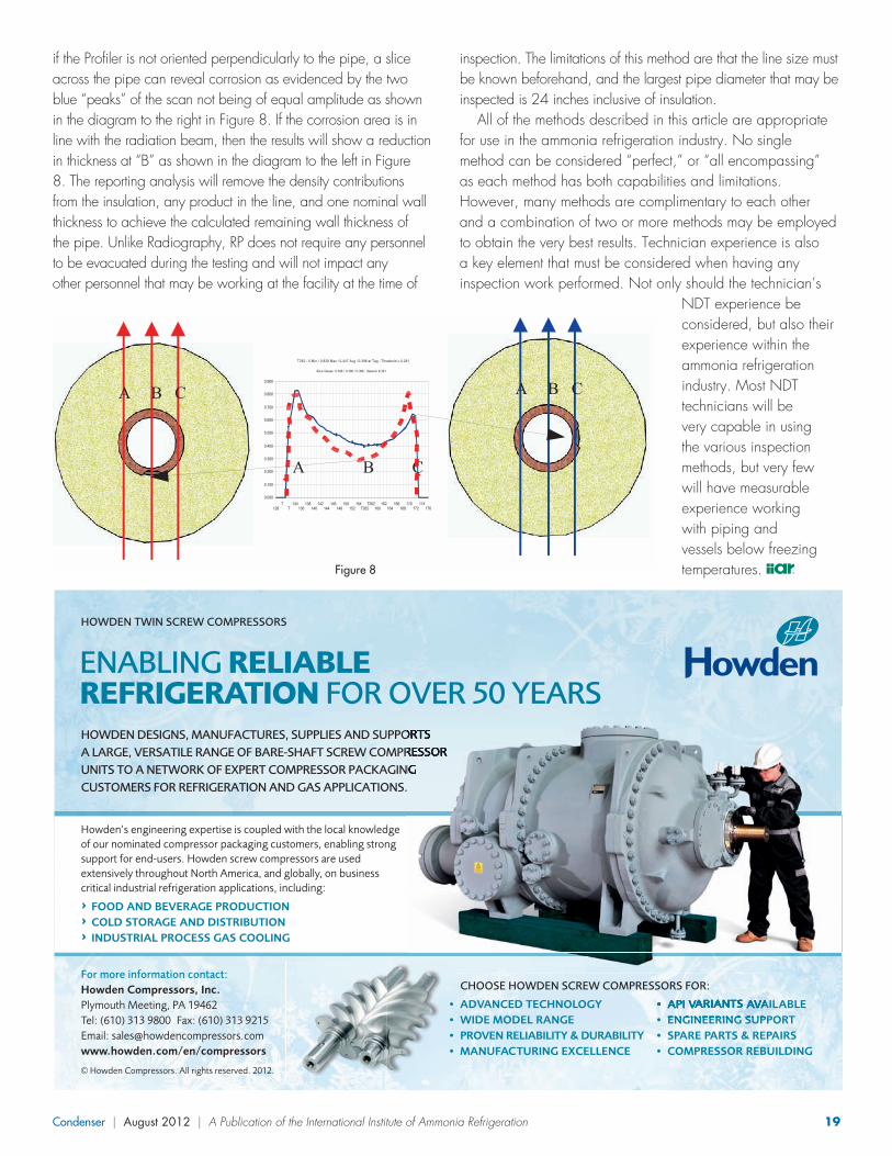
Condenser | August 2012 | A Publication of the International Institute of Ammonia Refrigeration 19
inspection. The limitations of this method are that the line size must be known beforehand, and the largest pipe diameter that may be inspected is 24 inches inclusive of insulation.
All of the methods described in this article are appropriate for use in the ammonia refrigeration industry. No single method can be considered “perfect,” or “all encompassing” as each method has both capabilities and limitations. However, many methods are complimentary to each other and a combination of two or more methods may be employed to obtain the very best results. Technician experience is also a key element that must be considered when having any inspection work performed. Not only should the technician’s
NDT experience be considered, but also their experience within the ammonia refrigeration industry. Most NDT technicians will be very capable in using the various inspection methods, but very few will have measurable experience working with piping and vessels below freezing temperatures.
if the Profiler is not oriented perpendicularly to the pipe, a slice across the pipe can reveal corrosion as evidenced by the two blue “peaks” of the scan not being of equal amplitude as shown in the diagram to the right in Figure 8. If the corrosion area is in line with the radiation beam, then the results will show a reduction in thickness at “B” as shown in the diagram to the left in Figure 8. The reporting analysis will remove the density contributions from the insulation, any product in the line, and one nominal wall thickness to achieve the calculated remaining wall thickness of the pipe. Unlike Radiography, RP does not require any personnel to be evacuated during the testing and will not impact any other personnel that may be working at the facility at the time of
NDT METHODS FOR THE AMMONIA REFRIGERATION INDUSTRY
valves that may have been covered by
insulation, weld lines, and rust scale on
the surface of the pipe (Fig. 5). However,
since it is not capable of penetrating the
pipe itself, no pipe wall thickness
information is acquired. The RTR
operator will identify areas on the
insulated piping for additional inspection
with other complimentary NDT methods
for a more quantitative conditional
assessment of the pipe. Figure 5 shows an
RTR operator and an image of small
diameter piping taken through insulation.
Radiometric Profiling (RP) was
specifically designed to assess the
integrity of piping through insulation
quickly and semi-quantitatively. This
technique involves a highly collimated
beam of low intensity radiation being
directed through the pipe. The total
density contributions from the pipe, the
product in the pipe, and the insulation are
represented as a total steel-thickness
graphically on the computer display. This
real-time graphical display of density in
terms of steel thickness is available to the
operator so that he or she can recognize
various anomalies that may be encountered. Advantages include the ability to “Slice” across or “Scan”
along insulated pipe without having to remove insulation. Pits can be identified and evaluated for
metal loss as long as the radiation beam is directed across them. Figure 6 depicts an RP slice conducted
Figure 8
A B C
128T
T134
136138
140142
144146
148150
152154
T262T262
160162
164166
168170
172174
176
0.000
0.100
0.200
0.300
0.400
0.500
0.600
0.700
0.800
0.900
T262 : 0 Min / 0.828 Max / 0.447 Avg / 0.398 at Tag : Threshold = 0.281
Slice Values: 0.398 / 0.398 / 0.398 : Session # 291
A B C
A B C
Figure 6
143 149 T125T 152 T125
161164
167
0.000
0.100
0.200
0.300
0.400
0.500
0.600
T125 : 0 Min / 0.553 Max / 0.313 Avg / 0.377 at Tag : Threshold = 0.281
Sli c e Va l ues : 0 .377 / 0 .37 7 / 0 .377 : Ses s i on # 1 3
A B C
A B C
Figure 7
4254
T219T
50 5862 70
7478
8286
0.0000.100
0.200
0.3000.400
0.5000.600
0.700
0.8000.900
T219 : 0 Min / 0.845 Max / 0.401 Avg / 0.679 at Tag : Threshold = 0.281
Sl i c e Va lue s : 0 .4 47 / 0 .6 79 / 0 .67 9 : Ses s io n # 27 9
A B C D E
A B C D E
Figure 8
HOWDEN DESIGNS, MANUFACTURES, SUPPLIES AND SUPPORTS A LARGE, VERSATILE RANGE OF BARE-SHAFT SCREW COMPRESSORUNITS TO A NETWORK OF EXPERT COMPRESSOR PACKAGINGCUSTOMERS FOR REFRIGERATION AND GAS APPLICATIONS.
Howden’s engineering expertise is coupled with the local knowledgeof our nominated compressor packaging customers, enabling strongsupport for end-users. Howden screw compressors are usedextensively throughout North America, and globally, on businesscritical industrial refrigeration applications, including:
^ FOOD AND BEVERAGE PRODUCTION^ COLD STORAGE AND DISTRIBUTION^ INDUSTRIAL PROCESS GAS COOLING
HOWDEN TWIN SCREW COMPRESSORS
ENABLING RELIABLE REFRIGERATION FOR OVER 50 YEARS
• API VARIANTS AVAILABLE• ENGINEERING SUPPORT• SPARE PARTS & REPAIRS• COMPRESSOR REBUILDING
CHOOSE HOWDEN SCREW COMPRESSORS FOR:
• ADVANCED TECHNOLOGY• WIDE MODEL RANGE• PROVEN RELIABILITY & DURABILITY• MANUFACTURING EXCELLENCE
For more information contact:Howden Compressors, Inc.Plymouth Meeting, PA 19462Tel: (610) 313 9800 Fax: (610) 313 9215Email: [email protected]/en/compressors
© Howden Compressors. All rights reserved. 2012.
HOG2461_Condenser_refrigeration_ad_half_page_AW 18/04/2012 10:04 Page 1
98363_IIAR_AugCond.indd 19 8/7/12 10:21 AM

20 Condenser | August 2012 | A Publication of the International Institute of Ammonia Refrigeration
by Chris Combs, International Programs Director
IIAR Alliance Grows in IndiaAs home to seventeen percent of the world’s population,
preserving India’s food supply is a major endeavor; yet about 30 percent of food production in India goes to waste, highlighting the need for more large cold storage and food processing facilities where ammonia is the refrigerant of choice. Industrial ammonia refrigeration is a rapidly growing sector in India and there is an increasing need for resources for the development of ammonia refrigeration professionals and facilities in India. This need, along with the encouragement of IIAR, led to the creation of India’s new Association of Ammonia Refrigeration (AAR) based in Pune, India’s eighth largest city located southeast of Mumbai in Maharashtra state. Besides being a center of manufacturing, Pune and the surrounding region have a thriving food processing industry, making it a natural hub for refrigeration industry contractors, manufacturers and consultants. AAR provides a common base in India for ammonia refrigeration knowledge, training and advice for the government on standards and regulations affecting the industry.
Since its foundation last year, AAR has offered numerous educational seminars around India. AAR’s first seminar was conducted in Chennai in Tamil Nadu state, on December 23, 2011. The seminar included presentations in both English and Tamil on ammonia refrigeration system maintenance and safety practices as well as the selection and operation of safety controls. Part of the IIAR safety series of training videos were presented at the seminar and were very well received; the attendees requested that a separate workshop be organized featuring more content from these DVDs.
The Chennai event was followed by a pair of seminars in the state of Maharastra, conducted by both the ASHRAE Pune chapter and AAR, on the “Best Practices for Design, Operation and Maintenance of Refrigeration Systems;” the first, in Ratnagiri on the western coast, was geared to seafood and cold storage facilities while the second, held in Miraj, focused on cold storage and dairy plants. Both seminars attracted over 100 attendees.
On May 12th, 2012, IIAR Honorary Life Member Godan Nambudiripad conducted a safety workshop organized by AAR and the ASHRAE Pune Chapter meeting in Pune. IIAR helped develop the content for this workshop beginning with a discussion of safety fundamentals and how ammonia refrigeration design and safety evolved in the United States. Other topics covered included commissioning, operations, maintenance, emergency response, the business case for safety and the first steps for implementing a safety program. During the program, Godan demonstrated different types of safety equipment which were donated to AAR on behalf of IIAR for use in future programs on ammonia safety. The 110 attendees represented cold stores, breweries, dairy facilities and other food and beverage plants. Feedback from the attendees was very positive and stressed the need for many more similar events throughout India.
At the end of June, IIAR President Bruce Badger and AAR President Nikhil Raj signed a memorandum of understanding regarding future IIAR-AAR cooperation which had been approved by IIAR’s Board of Directors on June 6. According to the memorandum of understanding, IIAR and AAR will exchange news publications, have a presence at the annual meetings and exhibitions of the other association, share technical expertise and experience, and establish and maintain strategic initiatives that benefit both organizations.
India and South Asia make up one of the official regions in the new IIAR International Committee structure unveiled at this year’s Ammonia Refrigeration Conference in Milwaukee. In April, AAR’s Board of Directors nominated Samir Shah, AAR’s Program Committee Chairman, to serve as the International Committee’s Regional Vice Chair for India and South Asia. The IIAR Board of Directors and International Committee Chairman Paul Bishop officially approved Samir Shah’s nomination as a Regional Vice Chair in June. AAR has already begun to engage the industrial refrigeration community in other countries in this region which includes Bangladesh, Sri Lanka, Myanmar and Malaysia. For example, AAR organized a program on June 8 and 9 in Colombo, Sri Lanka’s largest city, on designing safe ammonia refrigeration systems. Upon learning about AAR and IIAR activities, members of the industry in Sri Lanka discussed forming their own association to promote ammonia refrigeration.
Global View
98363_IIAR_AugCond.indd 20 8/7/12 10:21 AM

Condenser | August 2012 | A Publication of the International Institute of Ammonia Refrigeration 21
98363_IIAR_AugCond.indd 21 8/7/12 10:21 AM

22 Condenser | August 2012 | A Publication of the International Institute of Ammonia Refrigeration
have the same requirements for location and temperature as emergency showers.
Finally, permanent eye/face wash equipment is defined by ANSI as including any device used to flush the eyes and face simultaneously. This equipment should be capable of delivering 3.0 gpm of fluid for 15 minutes and have the same requirements for location and temperature as emergency showers.
The ANSI standard allows facilities to use temporary units, such as drench hoses and personal wash units, to supplement or replace permanent units under certain conditions.
According to ANSI, drench hoses are defined as flexible hoses connected to a water supply used to irrigate and flush the eyes, face and body area. The hoses should support shower and eyewash units, “but shall not replace them.” Drench hoses must also be capable of delivering
tepid flushing fluid at temperatures between 60°F to 100°F. The
hoses may also be considered an eyewash or eye, face wash device if their performance meets the performance
requirements laid out for permanent
devices.
Under the risk safety matrix laid out by Jordan, drench hoses are the kind of temporary device that could be used in places where ammonia exposure is rarely likely. In that scenario, a facility would install hard water lines in locations where a temporary hose could be set up prior to engaging in an operation that might introduce risk, for example during line breaking. “The idea is to have hard-piped water lines set up and ready to be turned on before they might be needed,” said Jordan. “Most of the time, that line is dry, but when you’re ready to do work where it might be required, that line is on and ready.”
The second type of temporary safety equipment is defined by ANSI as a personal wash unit. These are supplementary units that support plumbed and, or gravity-fed units. The personal wash unit must be capable of delivering immediate flushing fluid to the eyes or body to provide relief in the crucial seconds that pass before an approved station can be reached. There are no minimum flow requirements for this temporary option, and the only temperature requirement is that they be protected from freezing and ambient temperatures above 100°F.
Personal wash units represent the last line of defense in Jordan’s risk safety matrix, and might be used in cases where exposure risk exists in hard-to-reach or seldom occupied areas. “The use of this kind of equipment comes with a huge provisory,” said Jordan. “It’s something portable that would be carried to an area, but it’s only there to provide limited protection until a permanent station can be reached.”
Once a company has gained a clear understanding of the available equipment options for permanent and temporary eyewash and shower units, the next step is to determine what equipment to place in which locations. Jordan’s risk matrix does this by defining the number, type and location of
Emergency Eyewash and Shower Equipment continued from page 6
Permanent Eye/Face Wash Equipment
Temporary Equipment, Drench Hose
Temporary Equipment, Personal Wash Unit
98363_IIAR_AugCond.indd 22 8/7/12 10:21 AM
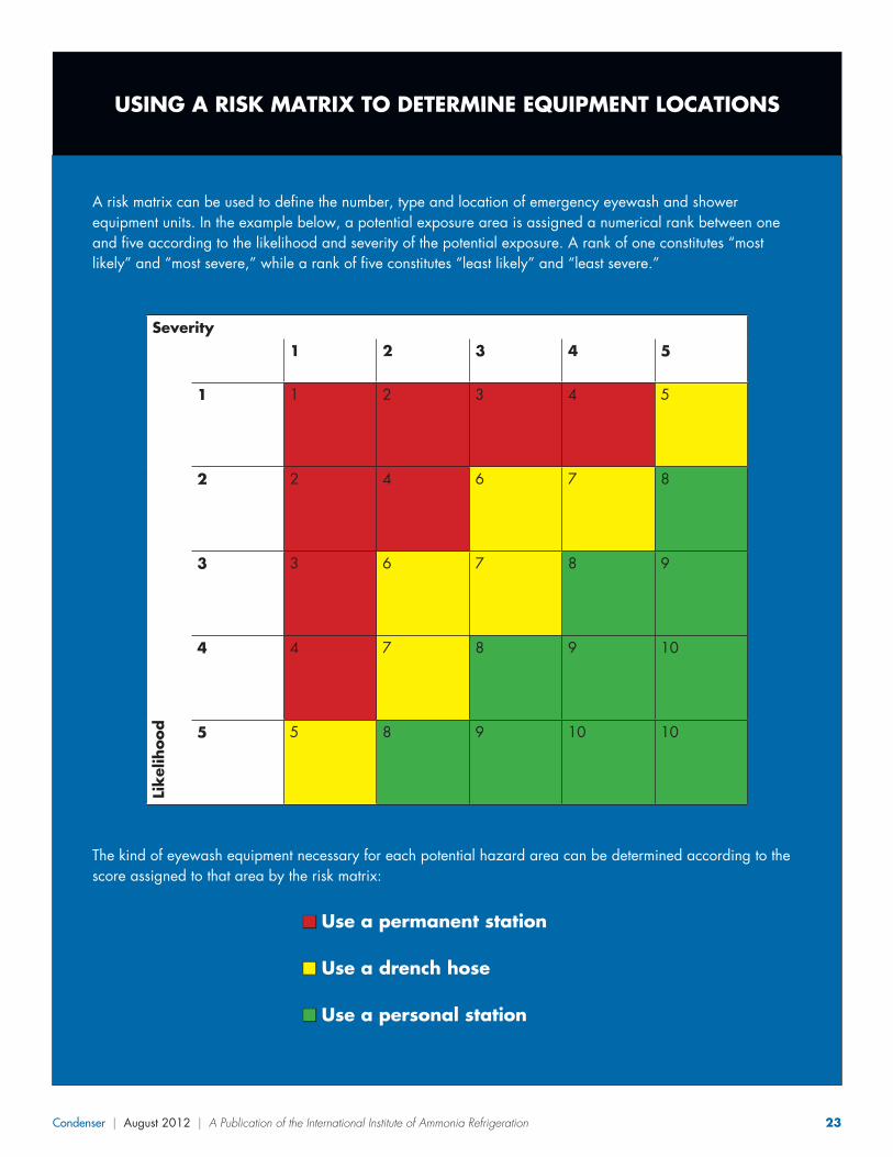
Condenser | August 2012 | A Publication of the International Institute of Ammonia Refrigeration 23
A risk matrix can be used to define the number, type and location of emergency eyewash and shower equipment units. In the example below, a potential exposure area is assigned a numerical rank between one and five according to the likelihood and severity of the potential exposure. A rank of one constitutes “most likely” and “most severe,” while a rank of five constitutes “least likely” and “least severe.”
Severity
Lik
elih
ood
1 2 3 4 5
1 1 2 3 4 5
2 2 4 6 7 8
3 3 6 7 8 9
4 4 7 8 9 10
5 5 8 9 10 10
The kind of eyewash equipment necessary for each potential hazard area can be determined according to the score assigned to that area by the risk matrix:
n Use a permanent station
n Use a drench hose
n Use a personal station
USING A RISK MATRIX TO DETERMINE EQUIPMENT LOCATIONS
98363_IIAR_AugCond.indd 23 8/7/12 10:21 AM

24 Condenser | August 2012 | A Publication of the International Institute of Ammonia Refrigeration
Like any hazard evaluation, recommendations identified during this process should be addressed on a timely basis.
Overall, the risk matrix as applied to eyewash safety programs has provided “reasonable” results when it comes to ensuring that the possible ammonia exposure risks in a facility have been thoroughly considered and prepared for, said Jordan. He added that the plan can help companies avoid the significant expense of installing permanent eyewash and shower stations in all ammonia locations where measures like the extensive use of drench hoses may be adequate.
Nevertheless, companies should consider these decisions carefully and always emphasize the appropriate levels of preparedness, said Jordan.
“We’re dealing with a potentially corrosive material when we work with ammonia. If the extreme happens, that’s not the time to find out you don’t have the right eyewash and shower capabilities in the right places,” said Jordan. “It’s all about pre-planning. Make sure you know ahead of time how you’re going to deal with as many potential situations as possible.”
emergency eyewash and shower equipment units needed. The higher a facility area ranks on the matrix according to the likelihood and severity of a potential exposure, the more likely it is to require a permanent station, while a lower rank may indicate that a drench hose or personal station will constitute adequate risk preparation.
The matrix can be applied to ammonia and other corrosive materials handled on-site at a facility. “The trick is to use the ranking system to decide where you want to implement each kind of equipment,” said Jordan. “All three options are suitable as long as they are done correctly.”
Matrix definitions for severity and likelihood of ammonia exposure are ranked one through five with a score of five representing the least severe or likely cases and a score of one representing the most severe or likely cases.
Suggested definitions for severity of exposure include: a large volume of ammonia (representing a score of one); a large volume of ammonia vapor (representing a score of two); a smaller volume of liquid ammonia (representing a score of three); the presence of an ammonia valve station (representing a score of four); and ammonia piping with no valve stations (representing a score of five).
Suggested definitions for likelihood of exposure include: line breaking once a week (representing a score of one); line breaking once a month (representing a score of two); line breaking once a quarter (representing a score of three); line breaking once a year (representing a score of four); and line breaking less than once a year (representing a score of five).
While smaller facilities may not adhere to Jordan’s risk matrix exactly, the scoring system is a good way to identify which risk options to use where a situation seems ambiguous. “Facilities may not use such a formal approach each time they build or evaluate an eyewash and safety shower plan,” said Jordan. “This is a way to decide how much ammonia is out there and what approach to use.”
As for how to actually implement and monitor any plan developed with an eyewash and safety shower risk matrix, Jordan recommends supporting the core plan with a variety of additional precautions and safeguards such as employing written procedures in each use case, implementing a “buddy system” to promote accountability and wearing appropriate personal protective equipment (PPE).
In larger facilities Jordan often participates in a team made up of two or three members to conduct an informal eyewash and safety shower evaluation. Members of the team should know the location and use of ammonia equipment as well as the location of emergency eyewash and shower equipment. The team typically tours the facility and then uses a site map to identify areas that should be ranked on the risk matrix. The evaluation typically results in recommendations where additional permanent or temporary units should be provided.
Defining Severity and LikelihoodFacilities should establish a clear method to determine where to install different kinds of emergency eyewash and shower equipment according to the risk and likelihood of exposure to ammonia. While an individual facility may have location-specific definitions of what constitutes severity and likelihood, the following common scenarios can serve as a foundation for these definitions:
Suggested Definitions for Severity:
1: Large volume of liquid ammonia
2: Large volume of ammonia vapor
3: Smaller volume of liquid ammonia
4: Ammonia valve stations
5: Ammonia piping
Suggested Definitions for Likelihood:
1: Line breaking once a week
2: Line breaking once a month
3: Line breaking once a quarter
4: Line breaking once a year
5: Line breaking less than once a yearWHY SETTLE FOR LESS? GET THE
BESTPROTECTION!
Protect Your System.
50% less oil carry over to low side.Less oil in system coils.Low pour point.Cleaner system.Better heat transfer.Less oil consumption.
Protect TheEnvironment.
Non toxic.
Non hazardous.
Non carcinogenic.
Authorized by the USDAand NSF for use infederally inspected meatand poultry plants.
Protect Compressors,Pumps & Gear Boxes.
Oxidatively stable up to eight timeslonger than conventional oils.
Non carbon or sludge forming.
Reduced compressor wear.
Maximum bearing protection.
Less energy consumption.
CAMCO 717 AmmoniaRefrigeration Oils SaveTime and Money.
Protect your product and personnel, affordably!Features• Detect concentrations of ammonia as low as 25 PPM. Sensitivity control
adjustable from 25 to 800 PPM (1000 PPM for LBW-420).• Dependable, long-life, solid state circuitry• Contacts for operating auxiliary equipment• Contacts for common industry alarm systems• NEMA 4X, UL-listed CSA, IEC, IP66 enclosure• One year warranty on workmanship from time of sale• Service switch for servicing without alarming
Typical ApplicationsIndustrial coolers and freezers, compressor rooms, control rooms,loading docks, storage tank areas.
Available Options• Remote sensor with box and cable• High-low temperature sensor (LBW-420 only)• ABS washdown/utility tube• Battery back-up• Remote alarm light & horn unit
1441 Rice Street • St. Paul, Minnesota 55117-3899 Office: 651-487-8844 • Fax: 651-487-8857E-Mail: [email protected] product info at www.coolairinc.comMade in the USA
Model LBW-50 Model LBW-420
Integrate seamlessly with industry alarm systems
Ammonia Leak Detectorsfrom the leading supplier of ammonia refrigeration systems and controls
Early warning to your employees: Quick response toleaks, 24 hours a day. Meets OSHA requirements.Saves money: Possible 5 to 15% reduction in annualinsurance premiums as well as additional insurance coverage.
Specializing in Synthetic and Semi-SyntheticLubricants for Refrigeration,Food Processingand Industrial ApplicationsCorporate Office: 1441 Rice Street • St. Paul, MN 55117-3899Tel: 651-489-8828 • Fax: 651-487-8857 • Toll-free: 1-877-205-1234Mike L. Worms • email: [email protected]
98363_IIAR_AugCond.indd 24 8/7/12 10:21 AM

Condenser | August 2012 | A Publication of the International Institute of Ammonia Refrigeration 25
ASHRAE 15 included the requirement prior to that. If you are dealing with an existing facility that was built under a previous code, it’s important to research the regulations that governed at the time to determine applicable requirements, recognizing that current code requirements for leak detection and alarms are not retroactive to existing facilities.
In conclusion, there is no doubt that codes and standards could benefit from revisions that would clarify their intent and avoid widely ranging interpretations on the topics discussed in this article and others that are related. A task group working on behalf of IIAR’s code and standards committees is taking a closer look at regulations for refrigerant detection alarm systems and will be making recommendations on options to address these issues. The work of this task group is important because IIAR is the best organization to determine appropriate regulations for ammonia leak detection systems. If these issues aren’t addressed by IIAR, it seems likely that another organization will eventually step in to dictate a solution. IIAR will have to bear in mind that the issues being dealt with go beyond ammonia and solutions may eventually impact leak detection requirements for other refrigerants. Thereby, we welcome input from anyone with an interest or expertise in the subject.
WHY SETTLE FOR LESS? GET THE
BESTPROTECTION!
Protect Your System.
50% less oil carry over to low side.Less oil in system coils.Low pour point.Cleaner system.Better heat transfer.Less oil consumption.
Protect TheEnvironment.
Non toxic.
Non hazardous.
Non carcinogenic.
Authorized by the USDAand NSF for use infederally inspected meatand poultry plants.
Protect Compressors,Pumps & Gear Boxes.
Oxidatively stable up to eight timeslonger than conventional oils.
Non carbon or sludge forming.
Reduced compressor wear.
Maximum bearing protection.
Less energy consumption.
CAMCO 717 AmmoniaRefrigeration Oils SaveTime and Money.
Protect your product and personnel, affordably!Features• Detect concentrations of ammonia as low as 25 PPM. Sensitivity control
adjustable from 25 to 800 PPM (1000 PPM for LBW-420).• Dependable, long-life, solid state circuitry• Contacts for operating auxiliary equipment• Contacts for common industry alarm systems• NEMA 4X, UL-listed CSA, IEC, IP66 enclosure• One year warranty on workmanship from time of sale• Service switch for servicing without alarming
Typical ApplicationsIndustrial coolers and freezers, compressor rooms, control rooms,loading docks, storage tank areas.
Available Options• Remote sensor with box and cable• High-low temperature sensor (LBW-420 only)• ABS washdown/utility tube• Battery back-up• Remote alarm light & horn unit
1441 Rice Street • St. Paul, Minnesota 55117-3899 Office: 651-487-8844 • Fax: 651-487-8857E-Mail: [email protected] product info at www.coolairinc.comMade in the USA
Model LBW-50 Model LBW-420
Integrate seamlessly with industry alarm systems
Ammonia Leak Detectorsfrom the leading supplier of ammonia refrigeration systems and controls
Early warning to your employees: Quick response toleaks, 24 hours a day. Meets OSHA requirements.Saves money: Possible 5 to 15% reduction in annualinsurance premiums as well as additional insurance coverage.
Specializing in Synthetic and Semi-SyntheticLubricants for Refrigeration,Food Processingand Industrial ApplicationsCorporate Office: 1441 Rice Street • St. Paul, MN 55117-3899Tel: 651-489-8828 • Fax: 651-487-8857 • Toll-free: 1-877-205-1234Mike L. Worms • email: [email protected]
complete lack of guidance with respect to how ammonia detectors required in refrigerated process and storage areas should be handled. That perspective isn’t mentioned in any code or standard.
Given that the TLV-TWA concentration does not indicate an imminently hazardous condition, or necessarily an impending hazardous concentration, initiating an evacuation or emergency response at this concentration seems excessive. Certainly, the guidance in ASHRAE 15 Appendix F does not support such an interpretation. Instead, it is evident that the intent of refrigerant leak detection alarms is to gain the attention of a responsible party to have the situation investigated. In the case of ammonia, an increasing hazard level will become clearly evident based on an increasingly untenable odor level.
Before ending this discussion, it’s worth noting that ammonia was entirely exempted from leak detection and alarm requirements in previous editions of codes and standards because it was accepted that ammonia’s odor provided adequate warning of a release. For example, consider that the IFC didn’t begin requiring leak detection for ammonia refrigeration until the 2006 edition; although, IIAR-2 and
Code Update continued from page 10
98363_IIAR_AugCond.indd 25 8/7/12 10:22 AM

26 Condenser | August 2012 | A Publication of the International Institute of Ammonia Refrigeration
working from his insights on legislative and regulatory issues that impact IIAR. This committee will also serve as a vehicle to communicate on these activities to IIAR members. This is an exciting step for IIAR, and I’m honored to be of service as the committee chair.”
The Government Relations Committee is similar to other IIAR committees in that it will draw upon the experience and diversity of the IIAR membership, including contractors and engineers, but the new committee will also have an especially strong focus on end-user members, Stencel said.
The Government Relations Committee will have a variety of issues to tackle in the fall, once it is fully formed and ready to begin its work, said Stencel.
He added that among the many things on the agenda for the group, elevating the understanding of the environmentally friendly aspects of ammonia as a refrigerant will make the top of the list.
“We’re ready to really raise the profile of the green component of our work,” he said. “Government has many incentive programs designed to encourage the use of energy efficient equipment in many different industries. The food processing and related industries have traditionally not seen the same degree of focus on such incentive programs. Where applicable, we’ll advocate for incentives similar to those found in other industries, to encourage optimally designed ammonia refrigeration systems and get recognition for the efficient systems that already exist in our industry.”
Meanwhile, the Government Relations Committee will also focus on concerns voiced by the industry with respect to the application of codes and standards that affect ammonia refrigeration, Stencel said.
“With the formation of this committee, we’re working toward a good information sharing relationship with OSHA and other regulatory bodies to ensure that the appropriate standards are applied when ammonia refrigeration systems are evaluated,” Stencel said.
“We believe that given the concerns raised by IIAR membership regarding the OSHA National Emphasis Program for chemical facilities, the goals and objectives of this committee are particularly relevant at this time.”
The formation of the new committee is also relevant to IIAR’s membership because it represents IIAR’s response to member surveys conducted over the last decade, IIAR said. Those surveys indicated that IIAR members consider advocacy on behalf of the industry to be a primary purpose of the organization.
The IIAR Committees have always served as a forum for the open discussion and advancement of the important issues we face in our industry. Not only do IIAR committees
represent the collective interests of ammonia refrigeration professionals, but the work they accomplish provides an important foundation for many of the Institute’s long-term goals.
That’s why we’re introducing a new column in the Condenser to update our readers on current IIAR committee projects and plans for the future. In this space in each issue, we’ll focus on one committee at a time, delving into the purpose of the committee we’re spotlighting and the important issues that committee is currently tackling.
Some IIAR committees have been in existence since the formation of the organization, and others are newcomers, added in recent years in response to new issues or needs. However, all ten of them continue to accomplish the goals our industry has set forth. IIAR’s ten committees include: code; education; international; marketing; piping; research; safety; standards; CO2; and the newest addition, government relations.
Any IIAR member is invited to participate in the work of the organization’s committees, either by serving as an active member or by bringing an important issue to the attention of the appropriate committee. You’ll find a list of all the committees and their leaders on the opposite page. In the meantime, read on for our first committee spotlight, on the newly formed Government Affairs Committee.
IIAR Announces Formation of Government Relations Committee
The International Institute of Ammonia Refrigeration is pleased to announce that its newest member committee, dedicated to government relations, was formed this year to work directly with the Institute’s government affairs representative, Lowell Randel.
As IIAR continues to work on behalf of the industry with government officials both in the U.S. and in other countries, the new committee will tackle issues important to IIAR members and continue the organization’s tradition of advocacy on behalf of the industry.
Committee Chair, Mark Stencel, Vice President and General Manager, Vilter Manufacturing, will lead the group. Stencel said the committee is accepting new members and expects to be fully formed by September.
“As this committee is coming together, one of things we’ll be focused on is to engage in and understand the work of our government relations director,” said Stencel. “As such, we’ll be
Committee Update
98363_IIAR_AugCond.indd 26 8/7/12 10:22 AM

Condenser | August 2012 | A Publication of the International Institute of Ammonia Refrigeration 27
Code CommitteeChair: John Collins, American Industrial RefrigerationVice-Chair: Jeremy Klysen, Leo A. DalyIIAR Staff: Jeff Shapiro, International Code Consultants
Education CommitteeChair: Harold Streicher, Hansen Technologies CorporationVice-Chair: Nicky Rainbolt, LoTemp Equipment CompanyIIAR Staff: Andrea Fischer, IIAR
International CommitteeChair: Paul Bishop, Parker Hannifin CorporationIIAR Staff: Chris Combs, IIAR
Marketing CommitteeChair: Tim Facius, Baltimore Aircoil CompanyVice-Chair: Delmar Lehman, Johnson ControlsIIAR Staff: Eileen McKeown, IIAR
Piping CommitteeChair: Don Hamilton, EVAPCO Inc.Vice-Chair: Dennis Halsey, GEA Refrigeration North AmericaIIAR Staff: Asst. Technical Director, IIAR
Research CommitteeChair: Bruce Nelson, Colmac Coil ManufacturingVice-Chair: Jeff Welch, Welch Engineering CorporationIIAR Staff: Belinda Ross, IIAR
Safety CommitteeChair: Martin Timm, Praxair, Inc.IIAR Staff: Bruce Badger, IIAR
Standards CommitteeChair: Bob Czarnecki, Campbell Soup CompanyVice-Chair: Don Faust, Gartner Refrigeration & Mfg., Inc.IIAR Staff: Eric Smith, IIAR
CO2 CommitteeChair: Brian Marriott, Retired
Government Relations CommitteeChair: Mark Stencel, Vilter Manufacturing LLCVice-Chair: Don Stroud, Kraft FoodsIIAR Staff: Lowell Randel, Global Cold Chain Alliance
For Frozen Food Safety, Equipment Reliability & Extended Lubricant Service Life
Summit Industrial Products offers a full line of Food Grade lubricants that conforms to
the requirements of ISO 21469, ISO 9001:2008 and HACCP compliance programs governing
quality and food safety. These lubricants provide superior extreme pressure, heat
transfer and anti-wear properties for equipment reliability. They are resistant to oxidation,
deterioration and harsh chemicals to provide extended lubricant service life.
Depend on Summit NSF H1 & H2 Food Grade Lubricants
FG SERIES• 100% Synthetic PAO for compression of
ammonia NH3 or carbon dioxide CO2
• Very low carryover, greater system efficiency & cleanliness
• Documented with extended ODIs over 50,000 hours with ammonia
REFRIGERATION PRODUCTS YOU CAN TRUST:
Scan to see Summit’s food grade products
Summit Industrial Products
HySyn FG Series•100% Synthetic PAO for extreme
low temperature hydraulic and conveyor lubrication applications
IIAR Member
P.O. Box 131359 • Tyler, TX 75713 • Ph. 800.749.5823 • www.klsummit.com
IIAR ad_Layout 1 1/30/2012 10:59 AM Page 1
98363_IIAR_AugCond.indd 27 8/7/12 10:22 AM

28 Condenser | August 2012 | A Publication of the International Institute of Ammonia Refrigeration
98363_IIAR_AugCond.indd 28 8/7/12 10:22 AM

Condenser | August 2012 | A Publication of the International Institute of Ammonia Refrigeration 29
Motor cooling could be done by circulating oil from the motor to the oil cooler that would be required by scroll or screw compressors. This would allow operation at high pressure ratios and low mass flows.
LubricantsAutomatic operation of a very small ammonia LPR system
would benefit from use of a miscible lubricant such as a poly-alpha-glycol (PAG). PAG lubricants are very hydroscopic but, provided care is taken not to leave the lubricant exposed to atmosphere, this is not a significant problem when using ammonia. On the occasions when PAG lubricants have been used with ammonia, the author has not experienced problems but would prefer PAO lubricants for larger systems.
Use of a miscible lubricant would greatly simplify return of oil from the Low Pressure Receiver.
A simple distillation device of the type used with miscible refrigerants could be used. Such devices operate only when the system is running and they reduce the concentration of oil in the LPR to a level at which the oil returned balances the amount of oil that is being carried over.
Expansion DevicesPackaged systems using halocarbon refrigerants often
use capillary tube expansion devices or short tube orifices. Such devices are surprisingly efficient and are simple and trouble free. Unfortunately, though they are simple to make, performance is difficult to calculate because of the many variables involved.
In 2004 Payne and O’Neal (ref 1.) carried out experiments on several refrigerants and produced empirical formulae that matched the data.
The formulae confirm the fact that short-tube orifices are capable of passing much greater mass flows under conditions where the refrigerant, at the inlet to the orifice, is sub-cooled as opposed to conditions where the refrigerant is in the form of wet vapour.
It was concluded by the author that, if the heat exchanger below the LPR vessel were arranged to be vertical and if short-tube orifices leading from the high pressure side of the heat exchanger to the low-pressure liquid line were placed near the top and bottom of the heat exchanger, the upper orifice would act to modulate the mass flow according to the degree of wetness at its take-off point. This would result in the heat exchanger being flooded with high pressure liquid in the process of being sub-cooled; while the condenser and the line leading from it to the heat exchanger would be effectively drained. See Figures 3. and 4. This is the same effect that is produced by the relatively complicated float control of remote expansion valve that is used in the larger systems.
The tests of Payne and O’Neal were carried out using R12, R134a, R502, 407C and R410A. Their empirical equations were used to estimate orifice performance of the more environmentally friendly refrigerants R717 (ammonia), R152a, R1234ze, R1234yf, R290 (propane) and R744 (carbon dioxide). It would be desirable to confirm by experiment that the assumptions made in the calculations can be justified but this has not been done.
Active spread sheets were devised so that by entering, refrigerant, orifice dimensions, condensing temperature and sub-cooling, or inlet dryness, the mass flow through the orifice could be displayed.
Figure 1. shows a calculation for mass flow rate of ammonia through a 2mm diameter orifice under sub-cooled conditions.
Figure 2. shows a calculation for mass flow of ammonia through a 2mm diameter orifice under similar conditions except that the condition at inlet is 50% dry.
It can be seen that the mass flow of the wet vapour is only 13% of the mass flow obtained when the ammonia liquid at inlet is sub-cooled by 15K.
This indicates that the proposed method of level control is feasible.
Figure 3 shows mass flow through a particular orifice versus inlet condition and Figure 4 shows the circuit diagram of a suitable type of LPR system.
Control of liquid level at the top of a vertical heat exchanger would allow the absolute minimum charge of ammonia.
The liquid line from condenser to heat exchanger would be drained and the “liquid” line from orifice to evaporator would contain significant quantities of flash gas.
The cooler would contain a very small proportion by volume of liquid ammonia, spread evenly over the inner surface of the aluminium tubes by their special internal treatment.
The wet return line from cooler to LPR would contain an even smaller proportion of liquid ammonia than the cooler and the LPR need contain only enough liquid ammonia to flood the heat exchanger.
In practice, the system would be charged with sufficient ammonia to allow for the variation in charge required by the cooler under different conditions of loading.
Pressure drop in the cooler is minimal because of the small quantity of liquid ammonia that is present. Similarly pressure drop in the wet return line would be comparable to pressure drop in a dry expansion system because of low rates of overfeed.
In practice, it has been found that efficiency of the LPR system using aluminium air coolers can be higher than efficiency of pump circulated systems because of the high coefficients of heat transfer that can be obtained and because of low pressure drops.
Ammonia LPR to Small Commercial Systems continued from page 15
98363_IIAR_AugCond.indd 29 8/7/12 10:22 AM

30 Condenser | August 2012 | A Publication of the International Institute of Ammonia Refrigeration
Conclusions
1. Low Pressure Receiver refrigerating systems have been in use for many years.
2. Such ammonia refrigerating systems can be as efficient as any other system.
3. Such refrigerating systems can operate unmanned.
4. Such refrigerating systems could be fully sealed.
5. Such systems can operate with even lower charge than DX systems.
6. Methods have been devised that would allow design of very small systems.
Acknowledgements
The author would like to thank the Directors of Star Refrigeration Ltd for permission to publish this paper.
Thanks are also given to Mr A D Small for his excellent work in adapting the empirical formulae to Payne and O’Neal to various environmentally friendly refrigerants.
The author would also like to thank the Directors of the International Institute of Ammonia Refrigeration for inviting him to write the paper and for their technical help over many years.
References
1. Payne W V & O’Neal D L. A Mass Flow-rate Correlation for Refrigerants and Refrigerant Mixtures Flowing Through Short Tubes. HVACR Research Journal 902g 2004.
Figure 1
Figure 2
Figure 3 Figure 4
98363_IIAR_AugCond.indd 30 8/7/12 10:22 AM

Condenser | August 2012 | A Publication of the International Institute of Ammonia Refrigeration 31
When you belong to the IIAR Community your voice adds impact to our industry!
As a member of IIAR you join with over 2,000 individuals in more than 30 countries who share your enthusiasm and commitment to your career and profession as part of the industrial refrigeration community.
Thank you for being a member of IIAR through the 2011–2012 membership year.
We would greatly appreciate your support through the 2012–2013 membership year to come.
2011–2012 was an extremely successful year for IIAR, along with being accepted into the OSHA Alliance Program, IIAR also:
• ReleasedthenewlyintegratedProcess Safety Management and Risk Management Program Guidelines
• UpdatedtheAmmonia Piping Handbook
• PublishedtheANSI/IIAR1-2012StandardAmerican National Standard for Definitions and Terminology Used in IIAR Standards
• andsawarecordconferenceattendanceattheIIARInternationalConference&ExhibitioninMilwaukee, WI.
In the 2012–2013 membership year, IIAR plans to continue its forward momentum and investment in its members by:
• PublishingtheupdatedCarbon Dioxide Industrial Refrigeration Handbook
• IntensifyingthepromotionofourmemberinterestsbeforeregulatorybodiesincludingtheEPA,OSHA,andothercode-writingauthorities
• Committingtoupdatingandbroadeningouronlinepresence
• anddevelopingnewpublicationsandeducationalprograms.
We are looking forward to an exciting year full of amazing growth and new opportunities!
If you have not already renewed your membership, just logon to www.iiar.org with your username, member number and password, click on My IIAR and select Renew My membership.
[email protected] | 703-312-4200
98363_IIAR_AugCond.indd 31 8/7/12 10:22 AM

32 Condenser | August 2012 | A Publication of the International Institute of Ammonia Refrigeration
by Eric Smith, P.E., LEED AP, IIAR Technical Director
By now most all IIAR members are aware that the IIAR is endeavoring to create a suite of “cradle to grave” standards for the construction, operation and
de-commissioning of ammonia refrigerating systems. What many might not realize is how difficult standards writing can be. Attempting to create “one size fits all” standards is plagued with the reality that exceptions to typical construction and typical operations will always exist, and attempting to address one issue with tailored language can reveal shortcomings in other areas. This is to say that it is necessary that people use good judgment when applying these or any standards, and retain and provide decision supporting documents. A couple often questioned situations are described below.
It should first be noted that any standard’s or code’s scope should be examined. Many standards, including IIAR 2, state that the standard applies to parts, components, equipment and systems that are designed manufactured and installed subsequent to the adoption of the standard. This is the fabled “grandfather clause”. If there is ever a doubt about whether or not a portion of the system should be updated, the authority having jurisdiction should be contacted for verification, and that decision should be documented. You must also consider regulatory agency actions and decide if the facility will be compliant.
The discharge of relief vent headers is an often cited dilemma. IIAR 2 states: “The discharge from pressure relief vessels shall not be less than 15 feet (4.8 m) above the adjacent grade or roof level or as specified by the jurisdictional authority and shall be arranged to avoid spraying of refrigerant on persons in the vicinity.” This statement clearly is written in an attempt to protect people from exposure to ammonia, while providing an opportunity for flexibility. It is very often the case that RV discharge headers are routed vertically alongside evaporative condensers and discharge above them. This would normally exceed the 15 ft. requirement. But these days, condensers often have work platforms at the top which create a dilemma. To address this question when it arises, I have recommended that discharge headers be extended above the platform at least 7.25' – the OSHA “headroom” figure. The “roof level” phrase was an attempt to address situations where an adjacent roof is higher than the adjacent grade. What about when the adjacent roof is a 40' or even 80' tall cold room? Requiring that a header be routed 95' was almost certainly not the intent. But “wind
effect” down drafts caused by wind blowing against tall buildings could affect the dispersion of ammonia, too. In these cases, applying some good judgment is in order. One might consider that condensers are usually situated far enough away from walls to eliminate re-induction due to downdrafts, and could also apply this logic to the RV discharge. A consideration of prevailing winds could be used to determine if there was an issue. Or the use of dispersion modeling could also be used to influence the design.
ASHRAE 15 states “…A part of the refrigerating machinery room mechanical ventilation shall be… operated, when occupied, to supply at least 0.5 cfm/ft2 of machinery room area or 20 cfm/person…” IIAR 2 does not address the necessity for fresh air for occupants, but arguably should. IIAR 2 states that “normal ventilation need not be continuous and shall be activated by a) Space temperature (thermostat) b) A refrigerant detector at a value not greater than the corresponding TLV-TWA and c) Manual controls. Stating that normal ventilation need not be continuous was done to ensure that it is understood that modern controls can energize ventilation equipment reliably, and the old requirement for continuous ventilation of engine rooms no longer exists. One effect of the current method is that energy for heating outside air, particularly in cold climates, has been greatly reduced. But there is still a requirement for minimum ventilation air per ASHRAE 15. Calculations can be made to show that the equipment in the room will always require some outside air to exhaust equipment heat. If this is greater than the minimum fresh air requirement, then nothing more needs to be done. But if calculations show that the room may not require ventilation for temperature control, the designer might wish to install a small fan for fresh air and activate it by an occupancy sensor if other fans are not on. Or, a designer might show that leakage rates of dampers and the “thermal drive” of hot and cold air will always provide a minimum amount of fresh air.
Note that the IIAR is currently undertaking a project to ensure that applicable safety requirements in ASHRAE 15 will also be incorporated into IIAR standards. A line by line “gap analysis” is being performed in the interest of thoroughness. It is our hope that eventually IIAR standards will be the only ones required for guidance on the design, construction, and operation of ammonia mechanical refrigerating systems.
From the Technical Director
Phone: (1) 214.515.5000 www.PolyguardProducts.com
Innovat ion based. Employee owned. Expect more.
Corrosion Under Insulation (CUI) is eliminated with RG-2400® ReactiveGel® on the pipe.
Use Polyguard vapor barrier over the insulation to block moisture from the system.
From the North Slopeto North America’s Food & Beverage Producers
www.ReactiveGel.com/madVisit us at
98363_IIAR_AugCond.indd 32 8/7/12 10:22 AM

Condenser | August 2012 | A Publication of the International Institute of Ammonia Refrigeration 33Phone: (1) 214.515.5000 www.PolyguardProducts.com
Innovat ion based. Employee owned. Expect more.
Corrosion Under Insulation (CUI) is eliminated with RG-2400® ReactiveGel® on the pipe.
Use Polyguard vapor barrier over the insulation to block moisture from the system.
From the North Slopeto North America’s Food & Beverage Producers
www.ReactiveGel.com/madVisit us at
98363_IIAR_AugCond.indd 33 8/7/12 10:22 AM

High Efficiency Packaged Chillers
• NH3 – A Sustainable Refrigerant
• Low Refrigerant Charge
• Reduced Installation Costs
• Quality GEA Plate and Frame HX
• Reduced PSM Requirements
• GForce™ Touch-Screen Controls
Series
GEA Refrigeration Technologies
GEA Refrigeration North America, Inc.3475 Board Rd., York, Pennsylvania 17406Tel: 800-888-4337Tel: 717-767-6411Fax: 717-764-3627Email: [email protected]: www.geafes.com
12-9951 Galaxy Ad.indd 1 1/30/12 8:29 AM98363_IIAR_AugCond.indd 34 8/7/12 10:22 AM