HVAC APPLICATION OVERVIEW - wago. · PDF fileRoom Auto Off Manual SYSTEM SSM/QUIT Ventilation...
44
Room Auto Off Manual SYSTEM SSM/QUIT Ventilation macro 01 Control diagrams System Control structure HVAC APPLICATION OVERVIEW Solutions for Heating, Ventilation and Air Conditioning
Transcript of HVAC APPLICATION OVERVIEW - wago. · PDF fileRoom Auto Off Manual SYSTEM SSM/QUIT Ventilation...

Room
AutoOffManual
SYSTEM
SSM/QUIT
Ventilation macro 01
Con
trol
dia
gram
sS
yste
mC
ontr
ol s
truc
ture
HVAC APPLICATION OVERVIEWSolutions for Heating, Ventilation and Air Conditioning

– 2 –

TABLE OF CONTENTS
WAGO Building Application Solutions 4
Energy-Efficient Systems 6
HVAC Primary System Solutions 8
System Macros 12
System Macros Overview 16
Generation 18
Distribution 22
Consumption 26
Utilization 38
WAGO Services 40
Applications 42
– 3 –
WAGO BUILDING APPLICATION SOLUTIONS
WINSTA® — THE PLUGGABLE CONNECTION SYSTEM
INSTALLATION CONNECTORS
LIGHTING CONNECTORS
HIGH-CURRENT, DIN-RAIL TERMINAL BLOCKS
TOPJOB® S — THE DIN-RAIL TERMINAL BLOCK SYSTEM
DISTRIBUTION BOXES
– 4 –

ETHERNET
ETHERNET
flexROOM®
DMX
WAGO-I/O-SYSTEM
INTERFACE ELECTRONIC AND SYSTEM COMPONENTSSystem Components
Digital Input/Output Modules Analog Input/Output Modules Communication and Specialty Modules
Libraries System Macros
Relays and OptocouplersEPSITRON® Power Supplies
Interface Modules JUMPFLEX® Signal ConditionersCurrent Measurement
– 5 –

Information and communication
technology
Source: Working Group on Energy Balances (AGEB):Application balances for German energy sectors, 11/2013
Hot water9.4 %
Other38.8 %
Other83 %
Air conditioning
17 %
Room heating51.8 %
Heating applications55.2 %
Mechanical energy37 %
Cooling applications
Lighting3.4 %
2.3 %
2.1 %
ENERGY-EFFICIENT SYSTEMSPotential Energy Savings Via HVAC Automation
Leveraging Potential Energy-Savings
Efficient energy consumption, optimal system operation and continu-ous improvement are just a few requirements that buildings must con-tinue to meet — even after construction or renovation. Beyond rental prices, potential tenants must factor operating costs for energy and maintenance into the bottom line. Therefore, it pays to look closely at the main factors behind building energy costs. Take for example the German market, in which heating and cooling applications account for 57.3 % of total energy consumption. And of that, 51.7 % is devoted to room heating — making it the country’s largest energy consumer. With these unsustainable energy consumption levels driving the transition to renewable energy, savvy system planners are looking closely at the boiler room. Approximately 20 % of Europe’s final energy consumption could be saved by doubling boiler room energy efficiency via system-specific measures or by improving the energy efficiency of the building envelope. A key part of the solution lies in system-related applications. The measure of success here depends on leveraging the huge potential for savings through modernizing outdated heating technology. *
European nations have begun enacting policies to promote conservation, such as the new German Energy Saving Regulation (EnEV) that was enacted on May 1, 2014. Building contractors starting new construction projects must comply with this regulation. These new energy-saving guidelines are also applicable to building technology systems: heating, cooling, ventilation and lighting, as well as hot water supply.
The following parameters are used for determining energy efficiency:• the annual primary energy demand for systems engineering• thermal insulation of the outer shell• heat protection/summer thermal insulation• air-tightness of the outer shell• the minimum air exchange in residential buildings.
*Source: “Green Paper on Energy Efficiency or Doing More with Less” (March 2006)
– 6 –

NOTEOne basic requirement for planning a building’s technical systems: Everyone who participates in the construction shares a common and clear language. To accomplish this, the DIN EN ISO 16484-3 Standard, which outlines building automation and control systems, is a core component of the initiative.Furthermore, the DIN EN 15232:2012 Standard (Energy Perfor-mance of Buildings – Impact of Building Automation, Controls and Building Management) involves extensive calculations and simulations to assess the potential savings that could stem from modernization through automation. In offices, this standard allows up to 25 % heating-energy savings to be economically generated through building and room automation — without changing the building envelope. Users and system operators can have a major influence on energy consumption through automation. Examples include integrating an automated system switch-off (when not needed), or by intelligently adapting a room temperature and timer program to mirror room occupancy. These automated control functions enable you to fully exploit — and benefit from — potential savings. Therefore, combining HVAC macros with other CODESYS function blocks enables users to merge virtually every building system into one cohesive plan that effectively economizes the entire building.
Automatically regulating HVAC systems not only provides occupants with greater comfort, but it also systematically improves a building’s climate to maximize economy through minimized energy costs.
INFO
eu.bac is the European Building Automation and Controls Association and represents the European manufacturers for Home and Building Automation and Energy Service Companies. WAGO’s eu.bac membership demonstrates its commitment and expertise in automation and controls.
– 7 –
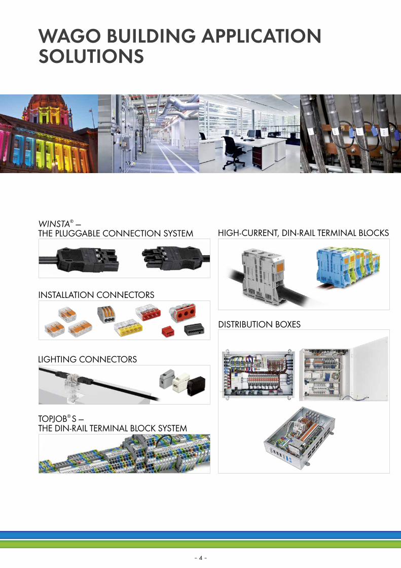
HVAC PRIMARY SYSTEM SOLUTIONSAn Efficient Process: Step-by-Step
Energy efficiency hinges on sensibly planning of a building’s technical systems. Modern automation systems conveniently combine all possible protocols and interfaces into one system — as opposed to the requirements of larger properties with mixed forms.The WAGO-I/O-SYSTEM 750 is the ideal hardware package for this challenge. The controller, which takes on control tasks for building automation, can be easily expanded using bus modules from a variety of systems — virtually any device can be connected to the system. Configuration, programming and visualization are easily performed using WAGO’s available software packages. In addition to building automation, WAGO has a well-established track record in building installations. This experience is reflected in WAGO’s integrated approach that cost-effectively combines these two worlds.
NOTE
The WAGO-I/O-SYSTEM: • Modular design• Fieldbus-independent• Planning freedom via flexible solutions• Future-ready, scalable solution
– 8 –
21,0 °C
▸ ▸ ▸
▸
StatusmeldungenSammelstörung:Vorspülen:Zuluftklappe:
OkVorspülen beendetgeö�net
Abluftklappe:Zuluftventilator:Abluftventilator:
geö�netOkOk
Level 2
Level 2
Sensorwerte übersteuern
Störung
Quit
12.0°C
31.0°C
15.0°C
100 % 0 %
18.0°C28.0°C
20.0°C22.0°C
Kon�gurationStartseite
I/O
NS
MS
LINKACTLINKACT
USR
X1
Termination+BIASON/OFF
Default IP
X2
BACnet/IP
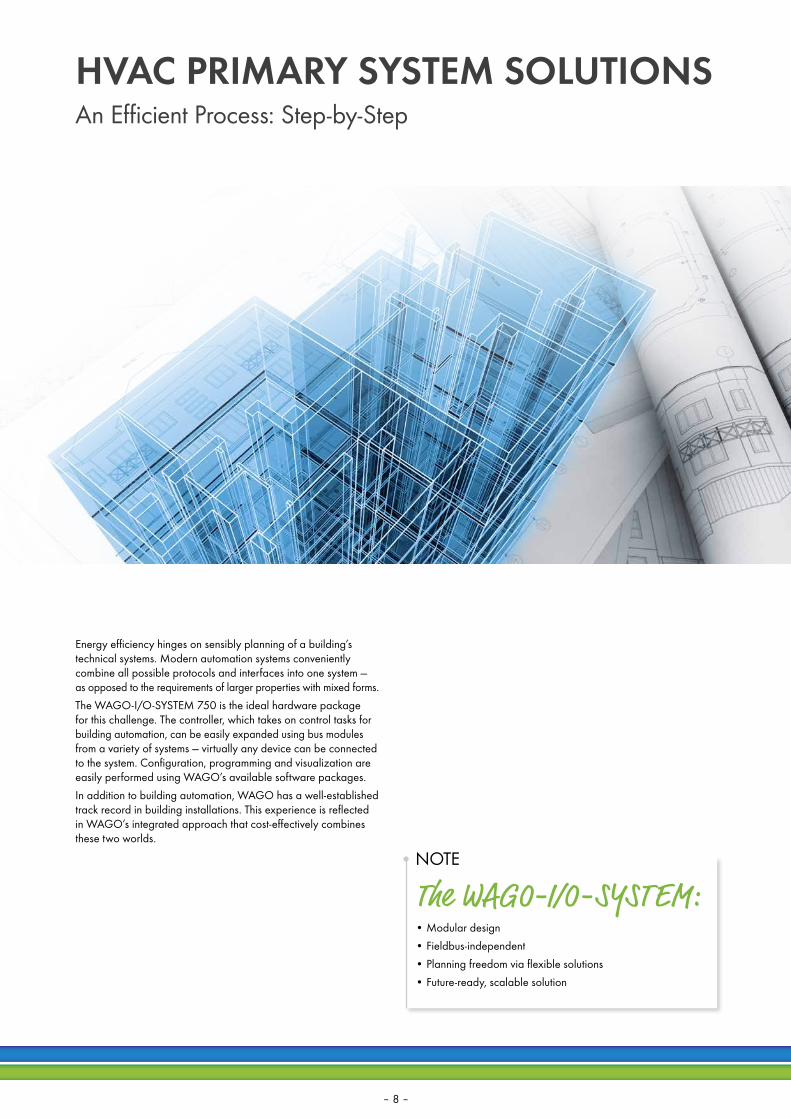
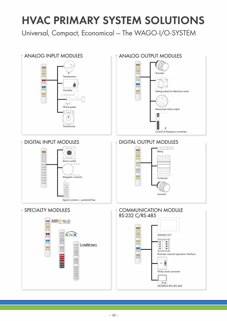
Universal, Compact, Economical — The WAGO-I/O-SYSTEM
Optimized for process-oriented communication, the WAGO-I/O-SYSTEM offers scalable performance and high integration density with an unbeatable price/ performance ratio.
At the management level, building automation is an integral part of both cost and facility management; it’s also a key component in overall building control. Open protocols link higher-level functions and building automation. To make the most of these protocols, WAGO offers software tools for commissioning and diagnostics to optimally support both system engineering and monitoring. Access to the Web visualization of each individual control unit is also performed at this management level. ETHERNET has long-established itself as the dominant medium at the automation level. As such, WAGO’s control units can be easily and efficiently interlinked using open, standardized bus protocols for building automation (e.g., BACnet IP, KNX IP or MODBUS/TCP). Standardized protocols and fast ETHERNET data transmission provide interoperable and future-ready interfaces between individual building technologies and levels.
Depending on the application, building automation systems can vary greatly from one building level to the next, requiring different transmission media (wired or wireless) and interfaces. Thus, flexible and easy-to-install media are required on the field level (room level). This is why WAGO offers a wide variety of solutions ranging from the direct control of standard sensors and actuators via interfaces to two-wire subsystems (e.g., DALI, BACnet MS/TP, KNX TP1 or LONWORKS®), on through to radio-based solutions such as, such as EnOcean or Bluetooth®.
ETHERNET
flexROOM®
MS/TP
IP
Actuator
For more information on BACnet, visit: www.wago.com/bacnet
– 9 –
°C
ÑÅ
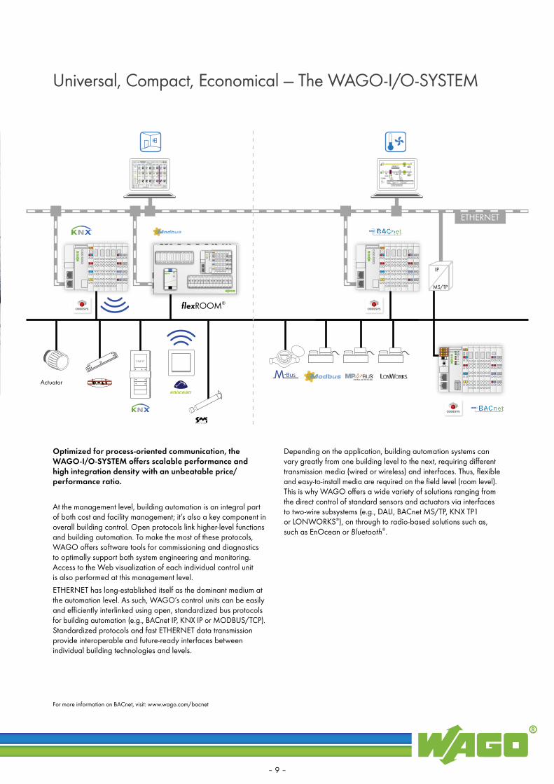
COMMUNICATION MODULE RS-232 C/RS-485
SPECIALTY MODULES
HVAC PRIMARY SYSTEM SOLUTIONSUniversal, Compact, Economical — The WAGO-I/O-SYSTEM
DIGITAL OUTPUT MODULESDIGITAL INPUT MODULES
ANALOG OUTPUT MODULESANALOG INPUT MODULES
Relay
Contactor
Actuator
Actuator
Measured value output
Setting values for electronic motor
Control of frequency converters
Alarm switch
Signal contacts — potential-free
Magnetic contacts
Wind speed
Humidity
Temperature
Transformer
PERSPECTO®
Romutec manual operation interface
M-Bus level converter
MODBUS RTU/RS-485
– 10 –

20.0°C
Heating circuit
Heating period
Manual
Optimization
Support mode
Heating curve ramp
Overheating/Condensation protection
Override ramp
20.0°C
25.0°C
45.0°C
51.0°C
0 %
50.4°C
5.0°C
0.0°C
5.0°C
30.0°CON
Max. thermostat
Con�guration
Basic WAGO Software
• Ready-to-use applications
• Economize system commissioning
• Reuse standardized solutions
• Customize via open source macros
• No extensive programming required
WAGO-I/O-CHECK
WAGO-I/O-CHECK is an easy-to-use Windows® application for checking inputs and outputs, as well as displaying a WAGO-I/O-SYSTEM 750 node.
Web VisualizationProject-specific visualizations are generated in the WAGO-I/O-PRO V 2.3 Software’s editor. The Web visualization can also be accessed on a tablet or smartphone using an app.
BACnet and MODBUS ConfiguratorWAGO also offers tools specifically engineered for select technologies, applications and products. Among these is WAGO’s BACnet and MODBUS Configurator, which allows devices connected to a specific network to be easily and efficiently addressed and parameterized.
HVAC System MacrosWith system macros, WAGO provides comprehensive modules with pre-configured functions to its customers; this dramatically streamlines project design and deployment by making most programming unnecessary.
WAGO-I/O-PRO V 2.3Using WAGO-I/O-PRO, programs can be individually created. In addition, pre- designed function blocks can also be accessed from software libraries. Graph-ically structured programs, such as those created with the Function Block Diagram (FBD) programming language, are very easy to create.
– 11 –

SYSTEM MACROSParameter Setting — Not Programming
WAGO provides comprehensive templates, which include ready- made system macros for many common applications. This time- saving convenience minimizes HVAC configuration for users. After rapidly configuring the application — via simple data point and system parameter assignment — the ready-made application can be directly commissioned.To simplify programming, there are a multitude of pre-configured function blocks and applications available free of charge in the download area. In addition, there are templates for creating programs. These comprehensive examples of complex tasks — including functional system macros with the appropriate docu- mentation — are available in PDF format.The manual override function within the system macros allows the operator to override individual system parts using the visualization screens.
System Macros
– 12 –

All current libraries and application notes can be downloaded at: www.wago.com/hvacdownload.
NOTE
Open Source!System macros are available as “open source” and can be tailored to meet individual system demands.
A system macro consists of various function blocks that are linked to other to enable the control of an entire ventilation system, for example. The function blocks consist of sub-functions that are com-bined to allow control of a larger task, such as a heating circuit. Using a system macro, you can also display and configure the entire system in a visualization interface.
– 13 –

Ventilation macro 01
Room
Contr
ol d
iagra
ms
Sys
tem
Contr
ol s
truct
ure
SYSTEM
SSM/QUIT
AutoOffManual
Ventilation macro 01
Room
Control diagrams
System
Control structure
SYSTEM
SSM/QUIT
AutoOffManual
SYSTEM MACROSParameter Setting — Not Programming
Matching the applications, standardized system diagrams for CAD and TRIC are available for easy integration into current plans.
Using the graphical function block representation, a macro’s functions can be clearly displayed to simplify assembly.
System Diagram Graphical Function Block Representation
– 14 –

Status messagesCollective malfunction:Pre�ushing:Mixed air damper:
OkPre�ushing: CompletedON
Exhaust air damper:
Incoming air fan: Exhaust air fan:
Open Humidi�er: OFF
OKOK
Overriding sensor values
Manual
Error
Quit
Y = 100.0 %
Y = 100.0 %
22.0°C
12.0°C30 %
31.0°C
50 %
8 %
0 %39 % 0 %
50 %15.0°C
6.35 g/m3
7.50 g/m3
6.35 g/m3
9.44 g/m3
1800 mBar2000 mBar
18.0°C25.4°C
20.0°C22.0°C
Con�gurationStart page
Connecting energy meters with M-Bus interface to the WAGO-I/O-SYSTEM
Application note
Last update: 05.10.14
System Macros Components
In addition to a visualization of the selected application, macros allow the user to easily adjust all relevant parameters through an online graphical interface.
Furthermore, the macros contain complete visualization interfaces for each completed application that allow you to monitor and control functions via the controller’s embedded Web server.
Configuration Visualization System Visualization
INFO
Application NoteIn addition to these graphical representations, the application note also includes a comprehensive function description, hardware information and a detailed tabular function block description.
– 15 –

Overriding sensor values
5.0°C
0.0°C
Manual
Quit
Ramp
Overheating protection
57.3°C
45.0°C
63.0°C
Manual
0 %
Manual Manual
QuitQuit
45.0°C
60.0°C
55.0°C
60.0°C
60 %
55.0°C63.0°C73.0°C
68.0°C71.0°C66.0°C
Overriding sensor values
Lead boiler: 1
Status: OK Status: OK
Manual
00 %
Boiler pump: Admixing pump: StageValve
Chimney sweep
Safety chain Safety chain
Chimney sweep
ONON
Quit
Heating period
Optimization
Support mode
Overheating protection
20.0°C20.0°C
50.6°C
5.0°C
12.0°C
5.0°C
Overriding sensor values
ManualON
Manual
SYSTEM MACROS OVERVIEWG
ENER
ATIO
NDI
STRI
BUTIO
NParameter Setting — Not Programming
• District heating transfer station with supply temperature control and return temperature limitation
• Boiler strategy with two dual-stage boilers• Boiler strategy with one dual-stage
and one modulating boiler
• Heating circuit with circulation pump• Heating circuit with heat exchanger,
supply temperature control and return temperature limitation
• Heating circuit with supply temperature control and return temperature limitation
District Heating Transfer Station Macros
Boiler Macros
Heating Circuit Macros
– 16 –

Overriding sensor values
Water heating
Hot water priority
Anti-Legionella function
Anti-Legionella alarm
Antifreeze protection
45.0°C
50.0°C45.0°C
Manual
Manual
ON
Manual
ON
Status messagesCollective malfunction:Pre�ushing:Air damper:
OKPre�ushing: CompletedOpen
Exhaust air damper:Incoming air fan:Exhaust air fan:
OpenOKOK
Level 2
Level 1
Overriding sensor values
Error
Manual
Quit
12.0°C
31.0°C
100 % 0 %
18.0°C22.0°C
15.0°C10.0°C
Manual
0 %
Manual
ON
Manual
Up
CON
SUM
PTIO
NU
TILI
ZATI
ON
• PID single-room controller
• Supply air temperature control or cascade control• Single-stage fan• Dual-stage fan• Mixed air fan with frequency converter• Plate-type heat exchanger • Run-around coil system • Rotary heat exchanger
• Full air-conditioning system • Fan with frequency converter• Mixed air humidification and
dehumidification
• Domestic water heating with charging pump
• Domestic hot water production with heat exchanger
• Domestic hot water production with supply temperature monitoring
Single-Room Control
Ventilation Macros
Domestic Water Heating Macros
– 17 –

District heating transfer station macro 01
Con
trol
dia
gram
sS
yste
mC
ontr
ol s
truc
ture
SYSTEM
SSM/QUIT
AutoOffManual
(Limit controller)
Limit controller
Setpoint adjustment
Overriding sensor values
5.0°C
0.0°C
Manual
Quit
Ramp
Overheating protection
57.3°C
45.0°C
63.0°C
Manual
0 %
GENERATIONDistrict Heat Macro
Heating Transfer Station with Supply Temperature Control and Return Temperature Limitation
The following requirements are met:
• Supply temperature setpoint with ramp function (crack protection)
• Adjustable offset to the reference supply temperature • PI supply temperature control • Anti-jamming function for valve • Return flow temperature limit based on outside temperature • Overheating protection using maximum thermostat
– 18 –

– 19 –

AutoOffManual
Boiler macro 01
Con
trol
dia
gram
sS
yste
mC
ontr
ol s
truc
ture
Level 1/2
Safety chain
Acknow-ledgement
Level 1Level 2
Level 1Level 2
Boiler 1 (or 2)Boiler 2 (or 1)
Boiler 1AutoOffManual
Level 1/2
Safety chain
Acknow-ledgement
Switching sequence control
Boiler 1/2
Boiler 2
Manual Manual
QuitQuit
45.0°C
60.0°C
55.0°C
60.0°C
60 %
55.0°C63.0°C73.0°C
68.0°C71.0°C66.0°C
Overriding sensor values
Lead boiler: 1
Status: OK Status: OK
Manual
00 %
Boiler pump: Admixing pump: StageValve
Chimney sweep
Safety chain Safety chain
Chimney sweep
ONON
GENERATIONBoiler Macros
Boiler Strategy with Two Dual-Stage Boilers
The following requirements are met:
BOILER STRATEGY • Boiler strategy for two boilers • Demand-dependent connection to the second boiler • Dynamic switching of the lead boiler • Automatic switching of the lead boiler in the event of a fault
BOILER CONTROL • Maximum limit of the boiler supply temperature • Minimum return flow temperature monitoring • Maximum return flow temperature limit • Unrestricted selection between mixing pump,
3-way valve and boiler damper • Boiler anti-condensation protection • Anti-jamming function for pumps and valve • Differing parameters for lead boiler and lag boiler • Different start-up processes based on the components used
– 20 –

Boiler macro 02
Con
trol
dia
gram
sS
yste
mC
ontr
ol s
truc
ture
Module
Safety chain
Acknow-ledgement
Level 1Level 2
Boiler 1 (or 2)Boiler 2 (or 1)
Boiler 1AutoOffManual
Level 1/2
Safety chain
Acknow-ledgement
Switching sequence control
Boiler 1/2
Boiler 2AutoOffManual
Manual
Chimney sweep
Manual
Chimney sweep
Safety chain Safety chain
QuitQuit
60.0°C
60.0°C
60.0°C
100 %
55.0°C63.0°C
73.0°C68.0°C
100 %
55.0°C66.0°C
Overriding sensor values
P = 87 %
Status: OK Status: OK
Manual
00 %
Boiler pump: Admixing pump: StageValve
ONON
Boiler Strategy with One Dual-Stage and One Modulating Boiler
The following requirements are met:
BOILER STRATEGY • Boiler strategy for two boilers • Demand-dependent connection to the second boiler • During normal operation, the modulating boiler
is always the lead boiler • Automatic switching of the lead boiler in the event of fault
BOILER CONTROL • Maximum limit of the boiler supply temperature • Constant maximum limit of the boiler supply temperature
for the modulating boiler • Minimum return flow temperature monitoring • Maximum return flow temperature limit • Unrestricted selection between mixing pump,
3-way valve and boiler damper • Boiler anti-condensation protection • Anti-jamming function for pumps and valve • Differing parameters for lead boiler and lag boiler • Different start-up processes based on the components used
– 21 –

Heating circuit macro 02
Con
trol
dia
gram
sS
yste
mC
ontr
ol s
truc
ture
SYSTEM
SSM/QUIT
AutoOffManual
Room
Weather-controlled
heating curve
Quit
Heating period
Optimization
Support mode
Overheating protection
20.0°C20.0°C
50.6°C
5.0°C
12.0°C
5.0°C
Overriding sensor values
ManualON
Manual
DISTRIBUTIONHeating Circuit Macros
Heating Circuit with Circulation Pump
The following requirements are met:
• Heating limit dependent on outside temperature to determine heating periods
• Selection between overnight economy mode (parallel shift of the heating curve) and overnight shutdown (support mode)
• Self-regulating start optimization • Heating curve • Mandatory override (e.g., overheating
protection of the primary system) • Anti-jamming function for the pump
– 22 –

Heating circuit macro 03
Con
trol
dia
gram
sS
yste
mC
ontr
ol s
truc
ture
SYSTEM
SSM/QUIT
AutoOffManual
Room
Weather-controlled
heating curve
Limit controller
Setpoint adjustment
(Limit controller)
Quit
Heating period
Optimization
Support mode
Heating curve ramp
18.0°C
35.0°C
55 %
20.0°C
40.5°C
5.0°C
12.0°C
5.0°C
Overriding sensor values
Manual
Heating Circuit with Heat Exchanger, Supply Temperature Control and Return Temperature Limitation
The following requirements are met:
• Heating limit dependent on outside temperature to determine heating periods
• Selection between overnight economy mode (parallel shift of the heating curve) and overnight shutdown (support mode)
• Self-regulating start optimization • Heating curve • Supply temperature setpoint with ramp function
(crack protection) • PI supply temperature controller • Return flow temperature limit based on outside temperature • Antifreeze controller • Pump switch-on is demand-dependent • Anti-jamming function for pump and valve
– 23 –

Heating circuit macro 01
Con
trol
dia
gram
sS
yste
mC
ontr
ol s
truc
ture
SYSTEM
SSM/QUIT
AutoOffManual
Room
Weather-controlled
heating curve
Limit controller
Setpoint adjustment
(Limit controller)
Quit
Heating period
Optimization
Support mode
Heating curve ramp
Overheating/Condensation protection
Override ramp
42.0°C
90 %
20.0°C20.0°C
50.6°C
5.0°C
12.0°C
5.0°C
Overriding sensor values
Manual
Chimney sweep
DISTRIBUTIONHeating Circuit Macros
Heating Circuit with Supply Temperature Control and Return Temperature Limitation
The following requirements are met:
• Heating limit dependent on outside temperature to determine heating periods
• Selection between overnight economy mode (parallel shift of the heating curve) and overnight shutdown (support mode)
• Self-regulating start optimization • heating curve • Supply temperature setpoint with ramp function
(crack protection) • PI supply temperature controller • Chimney sweep function with time limit • Mandatory override (e.g., domestic water heating
or overheating protection of the primary system) • Return flow temperature limit based on outside temperature • Antifreeze controller • Pump switch-on is demand-dependent • Anti-jamming function for pump and valve
– 24 –

– 25 –

Overriding sensor values
Water heating
Hot water priority
Anti-Legionella function
Anti-Legionella alarm
Antifreeze protection
45.0°C
50.0°C45.0°C
Manual
Manual
ON
Manual
ON
Heating circuit macro 02
Con
trol
dia
gram
sS
yste
mC
ontr
ol s
truc
ture
SYSTEM
SSM/QUIT
AutoOffManual
Room
Weather-controlled
heating curve
CONSUMPTIONDomestic Water Heating Macros
Domestic Water Heating with Charging Pump
The following requirements are met:
• Two-point temperature control, corresponding to the upper and lower storage tank temperature sensors
• Anti-Legionella function • Hot water priority function request • Charging and circulation pump control • Anti-jamming function for the pumps • Supply temperature setpoint
NOTE
Water tanks are prone to the formation of Legionella bacteria. To ensure the highest levels of safety and hygiene, WAGO domestic water heating macros are equipped with an anti-Legionella function. This mandatory function (heating to 70 °C) is activated by a timer program.
– 26 –

Overriding sensor values
Water heating
Hot water priority
Anti-Legionella function
Anti-Legionella alarm
Antifreeze protection
Manual
ON
Manual
53.0°C60.0°C55.0°C
65.0°C
68 %
Heating circuit macro 03
Con
trol
dia
gram
sS
yste
mC
ontr
ol s
truc
ture
SYSTEM
SSM/QUIT
AutoOffManual
Room
Weather-controlled
heating curve
Limit controller
Setpoint adjustment
(Limit controller)
Domestic Water Heating with Heat Exchanger
The following requirements are met:
• Storage tank control using a two-point controller • PI supply temperature control • Anti-Legionella function • Hot water priority function request• Charging and circulation pump control • Charging pump switch-on is demand-dependent • Anti-jamming function for pumps and valve • Supply temperature setpoint
– 27 –

Overriding sensor values
Manual
ON
Valve0 %
Manual
Water heating
Hot water priority
Anti-Legionella function
Cooling protection
Overheating protection
Override ramp
Supply alarm
Anti-Legionella alarm
Antifreeze protection
45.0°C
63 %
50.0°C46.0°C
47.0°C60.0°C
65.0°C
Domestic hot water macro 01
Con
trol
dia
gram
sS
yste
mC
ontr
ol s
truc
ture
SYSTEM
SSM/QUIT
AutoOffManual
WBB requirement
WBB requirementCooling protection
T1 and T2
CONSUMPTIONDomestic Water Heating Macros
Domestic Water Heating with Supply Temperature Monitoring
The following requirements are met:
• Two-point temperature control, corresponding to the upper and lower storage tank temperature sensors
• Anti-Legionella function • Cooling protection • Mandatory override
(e.g., overheating protection of the primary system) • Hot water priority function request • Charging and circulation pump control • Charging pump switch-on is demand-dependent • Anti-jamming function for pumps and valve • Supply temperature setpoint
– 28 –

– 29 –

Ventilation macro 01
Room
Con
trol
dia
gram
sS
yste
mC
ontr
ol s
truc
ture
SYSTEM
SSM/QUIT
AutoOffManual
Status messagesCollective malfunction:Pre�ushing:Air damper:
OKPre�ushing: CompletedOpen
Exhaust air damper:Incoming air fan:Exhaust air fan:
OpenOKOK
Level 2
Level 1
Overriding sensor values
Error
Manual
Quit
12.0°C
31.0°C
100 % 0 %
18.0°C22.0°C
15.0°C10.0°C
Manual
0 %
Manual
ON
Manual
Up
CONSUMPTIONVentilation Macros
Supply Air Temperature Control with Single-Stage Fan
The following requirements are met:
• Single-stage fan with contactor and operational monitoring • Upstream and downstream frost protection • Switching-on the pumps is demand-dependent • Anti-jamming function for pumps and valves • Control of outside air and exhaust air dampers • Monitoring the outside air filter • Supply air temperature control with cooling/heating sequences • Optimized setpoint supply temperature measurement
NOTEOur ventilation macros meet the DIN EN 13779 standard — ventilation for non-residential buildings.
– 30 –

Ventilation macro 02
Room
Con
trol
dia
gram
sS
yste
mC
ontr
ol s
truc
ture
SYSTEM
SSM/QUIT
AutoOffManual
Cascade EXH/SUP temp.
Summer compensation
Status messagesCollective malfunction:Pre�ushing:Air damper:
OKPre�ushing: CompletedOpen
Exhaust air damper:Incoming air fan:Exhaust air fan:
OpenOKOK
Level 2
Level 1
Overriding sensor values
Error
Manual
Quit
12.0°C
31.0°C
100 % 0 %
18.0°C22.0°C
15.0°C10.0°C
Manual
0 %
Manual
ON
Manual
Up
Status messagesCollective malfunction:Pre�ushing:Air damper:
OKPre�ushing completedOpen
Exhaust air damper:Incoming air fan:Exhaust air fan:
OpenOKOK
Manual
Level 2
Level 2
Overriding sensor values
Error
Quit
12.0°C
31.0°C
34 % 0 %
18.0°C20.7°C
15.0°C10.0°C
20.0°C22.0°C
Manual
Up
Manual
Level 1Level 2
Cascade Control with Dual-Stage Fan
The following requirements are met:
• Dual-stage fan with contactor and operational monitoring • Upstream and downstream frost protection • Switching-on the pumps is demand-dependent • Anti-jamming function for pumps and valves • Control of outside air and exhaust air dampers • Monitoring the outside air filter • Energy-optimized room/exhaust temperature control
with summer increase per DIN 1946 • Supply air temperature control with cooling/heating sequences • Optimized setpoint supply temperature measurement
– 31 –

Ventilation macro 03
Room
Con
trol
dia
gram
sS
yste
mC
ontr
ol s
truc
ture
SYSTEM
SSM/QUIT
AutoOffManual
Manual
Up
Manual
ON0 %
Status messagesCollective malfunction:Pre�ushing:Mixed air damper:
OKPre�ushing completedON
Exhaust air damper:Incoming air fan:Exhaust air fan:
OpenOKOK
Manual
Overriding sensor values
Error
Quit
Y = 30.8 %
Y = 17.6 %
18.0°C
12.0°C
31.0°C
18.0°C22.0°C
30 %
25 % 0 %
15.0°C10.0°C
200 Pa200 Pa
200 Pa200 Pa
CONSUMPTIONVentilation Macros
Supply Air Temperature Control with Mixed Air and Fan with Frequency Converter
The following requirements are met:
• Continuous fan with contactor and operational monitoring • Pressure control in supply and exhaust air duct • Upstream and downstream frost protection • Switching-on the pumps is demand-dependent • Anti-jamming function for pumps and valves • Control of mixed air and exhaust air dampers • Monitoring the outside air filter • Supply air temperature control in
cooling/circulating/heating sequences • Optimized setpoint supply temperature measurement
– 32 –

Cascade EXH/SUP temp.
Summer compensation
Ventilation macro 04
Room
Con
trol
dia
gram
sS
yste
mC
ontr
ol s
truc
ture
SYSTEM
SSM/QUIT
AutoOffManual
Manual
Up
Manual
ON0 %
Manual
Overriding sensor values
Error
Quit
Y = 36.8 %
Y = 20.3 %
18.0°C
12.0°C
31.0°C
19.0°C23.1°C
30 %
25 % 0 %
20.0°C22.0°C
19.0°C10.0°C
200 Pa200 Pa
200 Pa200 Pa
Status messagesCollective malfunction:Pre�ushing:Mixed air damper:
OKPre�ushing completedON
Exhaust air damper:Incoming air fan:Exhaust air fan:
OpenOKOK
Cascade Control with Mixed Air and Fan with Frequency Converter
The following requirements are met:
• Continuous fan with contactor and operational monitoring • Pressure control in supply and exhaust air duct • Upstream and downstream frost protection • Switching-on the pumps is demand-dependent • Anti-jamming function for pumps and valves • Control of mixed air and exhaust air dampers • Monitoring the outside air filter • Energy-optimized room/exhaust temperature control
with summer increase per DIN 1946 • Supply air temperature control in
cooling/mixed air/heating sequences • Summer night ventilation • Optimized setpoint supply temperature measurement
– 33 –

Ventilation macro 05
Room
Con
trol
dia
gram
sS
yste
mC
ontr
ol s
truc
ture
SYSTEM
SSM/QUIT
AutoOffManual
Cascade EXH/SUP temp.
Summer compensation
Status messagesCollective malfunction:Pre�ushing:Air damper:
OKPre�ushing completedON
Exhaust air damper: Open
Heat exchanger:Incoming air fan:Exhaust air fan:
OKOKOK
Manual
Overriding sensor values
Error
Quit
Y = 79.4 %
Y = 34.0 %
Y = 17.4 %
Manual
Up
Manual
0 %
Manual
ON0 %
12.0°C
31.0°C
78 % 0 %
17.0°C23.5°C
100 %
2.0 Pa
15.0°C10.0°C
21.0°C22.0°C
200 Pa200 Pa
200 Pa200 Pa
CONSUMPTIONVentilation Macros
Cascade Control with Plate-Type Heat Exchanger and Fan with Frequency Converter
The following requirements are met:
• Continuous fan with contactor and operational monitoring • Pressure control in supply and exhaust air duct • Upstream and downstream frost protection • Switching-on the pumps is demand-dependent • Anti-jamming function for pumps and valves • Control of outside air and exhaust air dampers • Monitoring the outside air and exhaust air filters • Energy reclamation using plate heat exchanger
(cross-flow heat exchanger) • Energy-optimized room/exhaust temperature control
with summer increase per DIN 1946 • Supply air temperature control in
cooling/energy reclamation/heating sequence • Summer night ventilation • Optimized setpoint supply temperature measurement
– 34 –

Ventilation macro 06
Room
Con
trol
dia
gram
sS
yste
mC
ontr
ol s
truc
ture
SYSTEM
SSM/QUIT
AutoOffManual
Cascade EXH/SUP temp.
Summer compensation
Status messagesCollective malfunction:Pre�ushing:Air damper:
OKPre�ushing completedON
Exhaust air damper: Open
Heat exchanger:Incoming air fan:Exhaust air fan:
OKOKOK
Manual
Overriding sensor values
Error
Quit
Y = 79.4 %
Y = 34.0 %
Y = 17.4 %
Manual
Up
Manual
0 %
Manual
ON0 %
12.0°C
31.0°C
78 % 0 %
17.0°C23.5°C
100 %
2.0 Pa
15.0°C10.0°C
21.0°C22.0°C
200 Pa200 Pa
200 Pa200 Pa
Status messagesCollective malfunction:Pre�ushing:Heat exchanger:
OKPre�ushing completed
OpenON
Outside air bypass:Exhaust air bypass: Open
Outside air damper: Exhaust air damper:Incoming air fan:Exhaust air fan:
OpenOpen
OKOK
Manual
Overriding sensor values
Manual
ON0 %
Manual
ON0 %
Error
Quit
Y = 79.4 %
Y = 29.6 %
Y = 18.4 %
31.0°C
12 % 0 %
18.0°C21,0°C
3.0 Pa
100 %
12.0°C
21.0°C22.0°C
200 Pa200 Pa
200 Pa200 Pa
15.0°C10.0°C
Cascade Control with Run-Around Coil System and Fan with Frequency Converter
The following requirements are met:
• Continuous fan with contactor and operational monitoring • Pressure control in supply and exhaust air duct • Upstream and downstream frost protection • Switching-on the pumps is demand-dependent • Anti-jamming function for pumps and valves • Control of outside air and exhaust air dampers • Monitoring the outside air and exhaust air filters • Energy reclamation using closed-loop system (CLS) • Energy-optimized room/exhaust temperature control
with summer increase per DIN 1946 • Supply air temperature control in
cooling/energy reclamation/heating sequence • Summer night ventilation • Optimized setpoint supply temperature measurement
– 35 –

Ventilation macro 07
Room
Con
trol
dia
gram
sS
yste
mC
ontr
ol s
truc
ture
SYSTEM
SSM/QUIT
AutoOffManual
Cascade EXH/SUP temp.
Setpoint adjustment
Summer compensation
Status messagesCollective malfunction:Outside air damper:Exhaust air damper:
OKOpenOpen
Incoming air fan:Pre�ushing:
Exhaust air fan:OKPre�ushing completed
OK
ManualManual
Pump
Valve0 %
Manual
ON0 %
Overriding sensor values
Error
Quit
Y = 79.4 %
Y = 33.9 %
Y = 16.3 %
12.0°C
31.0°C
27 % 0 %
18.0°C22.8°C
100 %
15.0°C10.0°C
15.0°C10.0°C
20.0°C22.0°C
200 Pa200 Pa
200 Pa200 Pa
CONSUMPTIONVentilation Macros
Cascade Control with Rotary Heat Exchanger and Fan with Frequency Converter
The following requirements are met:
• Continuous fan with contactor and operational monitoring • Pressure control in supply and exhaust air duct • Upstream and downstream frost protection • Switching-on the pumps is demand-dependent • Anti-jamming function for pumps and valves • Control of outside air and exhaust air dampers • Monitoring the outside air and exhaust air filters • Energy recovery using rotary heat exchanger • Energy-optimized room/exhaust temperature control
with summer increase per DIN 1946 • Supply air temperature control in
cooling/energy reclamation/heating sequence • Summer night ventilation • Optimized setpoint supply temperature measurement
– 36 –

Ventilation macro 08
Room
Con
trol
dia
gram
sS
yste
mC
ontr
ol s
truc
ture
SYSTEM
SSM/QUIT
AutoOffManual
Cascade EXH/SUP temp.
Cascade EXH/SUP humidity
Summer compensation
Status messagesCollective malfunction:Pre�ushing:Mixed air damper:
OKPre�ushing completedON
Exhaust air damper:
Incoming air fan:Exhaust air fan:
Open Humidi�er: OFF
OKOK
Manual
Overriding sensor values
Error
Quit
Y = 76.8 %
Y = 62.4 %
18.0°C
12.0°C30 %
31.0°C
70 %
0 %
18 %0 % 5 %
70 %
10.78 g/kg5.00 g/kg
21.0°C26.4°C
21.0°C22.0°C
15.0°C10.0°C
8.93 g/kg7.50 g/kg
200 Pa200 Pa
200 Pa200 Pa
Manual
ON0 %
Manual
ON0 %
Manual
0 %
Manual
Up
Full Air-Conditioning System with Mixed Air and Fan with Frequency Converter
The following requirements are met:
• Continuous fan with contactor and operational monitoring • Pressure control in supply and exhaust air duct • Upstream and downstream frost protection • Switching-on the pumps is demand-dependent • Anti-jamming function for pumps and valves • Control of mixed air and exhaust air dampers • Monitoring the outside air filter • Energy-optimized room/exhaust temperature control
with summer increase per DIN 1946 • Supply air temperature control in
cooling/mixed air/heating sequences • Room/exhaust air humidity control • Supply air humidity control with
dehumidification/humidification sequences • Humidification via steam humidifier • Summer night ventilation • Optimized setpoint supply temperature measurement
– 37 –

UTILIZATIONSingle-Room Control
PID Single-Room Controller
This function block permits single-room temperature control while accounting for external factors.
• Separate PID controllers for heating and cooling• Three different operating modes
(comfort, standby and night)• Adjustable dead zone between heating and cooling• Setpoint correction via room operating panel• Window contact analysis to determine switch
to frost/heat protection (support mode) • Dew point detector monitoring
Antifreeze protection
Heat protection
Dead zone
35 °C 7 °C
17 °C
19 °C
21 °C
27 °C
25 °C
23 °CComfort mode
Operating mode
Heating setpoint
Cooling setpoint
Standby mode
Night mode
Frost/heat protection
Operating Mode Heating Setpoint Cooling Setpoint
Comfort mode Basic setpoint: 21 °C Basic setpoint + Dead zone: 2 K
Standby modeBasic setpoint, temperature decrease − Standby mode
Basic setpoint + Dead zone + Temperature increase, standby mode
Night modeBasic setpoint, temperature decrease − Night mode
Basic setpoint + Dead zone + Temperature increase, night mode
Frost/heat protection
Frost protection setpoint: 7 °C
Heat protection setpoint: 35 °C
Dew point alarm Setting value: 0 (heating off) Setting value: 0 (cooling off)
– 38 –

– 39 –

WAGO SERVICES
WAGO’s technical support staff is ready to assist every customer with advice and guidance: from selecting the right product, through telephone support during commissioning, all the way up to on-site troubleshooting. Customers directly benefit from knowledgeable WAGO experts, allowing them to implement their projects faster.
WAGO provides advice and support with: • Product selection• Product commissioning• Troubleshooting• Technical questions about WAGO’s wide product range
You can reach our support team by:Phone: +49 571 887 555 Email: [email protected] Contact form: www.wago.com > SERVICES > SUPPORT HOTLINES > Technical Support AUTOMATION
Technical Support Project Support
WAGO’s technical support offers consultation and project planning services to help devise the best possible solutions for your custom building automation and installation projects. Our experienced team of professionals will gladly help you implement your projects with WAGO products.
Large-scale applications include:• Production facilities and warehouses• Office buildings• Shops and display areas• Schools• Hospitals• Airports
WAGO helps customers with: • Advice while planning construction projects
from experts with years of project experience• Customizing solutions to ensure the technical
and financial success of large projects• Technical support for implementing building projects
Planning and project engineering:• Conceptual design• Network planning• Application design• Component selection• Quote generation
– 40 –

WAGO Seminars
Innovative ideas and advanced technology are the driving forces behind the development and creation of WAGO’s market-leading products. Attending WAGO training seminars provides the appli-cation insight that enables you to maximize the benefits of WAGO products. The skills and expertise gained in our effective, user- oriented sessions will ultimately save you time and enable you to get the most from our products.
Professional Environment — Effective Learning• Small groups in which all questions will be addressed.• Collaborative learning, because education in a group setting
is more effective and encourages an exchange of experiences.• Highly practical — we believe your experiences form the ideal base
to build upon with product information that’s uniquely tailored to you.
WAGO Building Automation Seminars• Building automation using WAGO KNX components• Building automation using WAGO BACnet components• Building automation using WAGO LON® components• HVAC applications• DALI applications• EnOcean applications• flexROOM®
Custom, On-Site TrainingIn addition to these open-forum seminars, WAGO also offers sessions that are specifically tailored to your organization and its particular needs. Upon request, we can conduct these seminars at your location.
NOTETechnical Support www.wago.com/supportProject Support Do not hesitate to contact our support team: www.wago.com/project supportWAGO Seminars www.wago.com/seminars
– 41 –

APPLICATIONS
– 42 –

Volker Wiciok/vor-ort-foto.de
– 43 –
WAGO Kontakttechnik GmbH & Co. KGPostfach 28 80 · D - 32385 MindenHansastraße 27 · D - 32423 MindenGermanyPhone: +49 571 887- 0Fax: +49 571 887-169Email: [email protected]: www.wago.com
0888
-059
8/03
00-6
901
- HEA
TIN
G/V
ENTI
LATI
ON
/AIR
CO
N 3
.0 U
S - 0
2/15
- Pr
inte
d in
Ger
man
y - S
ubje
ct to
des
ign
chan
ges