Hustler Three Bag Catcher 54/60/66/72 Decks 3-1 REV F ASSEMBLY INSTRUCTION These instructions apply...
57
118551 REV F Hustler ® Three Bag Catcher 54"/60"/66"/72" Decks Operator’s Manual 200 South Ridge Road Hesston, Kansas 67062
Transcript of Hustler Three Bag Catcher 54/60/66/72 Decks 3-1 REV F ASSEMBLY INSTRUCTION These instructions apply...

118551 REV F
Hustler® Three Bag Catcher54"/60"/66"/72" Decks
Operator’s Manual
200 South Ridge RoadHesston, Kansas
67062

REV F 118551

118551 toc-1 REV F
Table of Contents
General Information . . . . . . . . . . . . . . . . . . . . . . . . . . . . . . . . . . . . . . . . . . 1-1
To the New Owner . . . . . . . . . . . . . . . . . . . . . . . . . . . . . . . . . . . . . . . . 1-1
Using This Manual . . . . . . . . . . . . . . . . . . . . . . . . . . . . . . . . . . . . . . . . 1-1
Warranty Registration. . . . . . . . . . . . . . . . . . . . . . . . . . . . . . . . . . . . . . 1-1
Parts and Service . . . . . . . . . . . . . . . . . . . . . . . . . . . . . . . . . . . . . . . . . 1-1
Safety Precautions . . . . . . . . . . . . . . . . . . . . . . . . . . . . . . . . . . . . . . . . . . . 2-1
Safe Operation and Service Precautions . . . . . . . . . . . . . . . . . . . . . . . 2-1
Safety and Instruction Decals. . . . . . . . . . . . . . . . . . . . . . . . . . . . . . . . 2-1
Assembly Instruction . . . . . . . . . . . . . . . . . . . . . . . . . . . . . . . . . . . . . . . . . 3-1
Packing List - 932467 Catcher . . . . . . . . . . . . . . . . . . . . . . . . . . . . . . . 3-1
Deck Adapter Kits. . . . . . . . . . . . . . . . . . . . . . . . . . . . . . . . . . . . . . . . . 3-1
Mower Deck Preparation . . . . . . . . . . . . . . . . . . . . . . . . . . . . . . . . . . . 3-1
121923 (54") Adapter Assembly . . . . . . . . . . . . . . . . . . . . . . . . . . . . . 3-3
113903 (60") Adapter Assembly . . . . . . . . . . . . . . . . . . . . . . . . . . . . . 3-4
113904 (66") Adapter Assembly . . . . . . . . . . . . . . . . . . . . . . . . . . . . . 3-5
113905 (72") Adapter Assembly . . . . . . . . . . . . . . . . . . . . . . . . . . . . . 3-6
Mower Preparation . . . . . . . . . . . . . . . . . . . . . . . . . . . . . . . . . . . . . . . . 3-7
Final Connection . . . . . . . . . . . . . . . . . . . . . . . . . . . . . . . . . . . . . . . . . 3-7
Catcher Hood Assembly. . . . . . . . . . . . . . . . . . . . . . . . . . . . . . . . . . . . 3-9
Weight Assembly . . . . . . . . . . . . . . . . . . . . . . . . . . . . . . . . . . . . . . . . 3-10
Operation . . . . . . . . . . . . . . . . . . . . . . . . . . . . . . . . . . . . . . . . . . . . . . . . . . 4-1
Vacuum Pickup and Collection. . . . . . . . . . . . . . . . . . . . . . . . . . . . . . . 4-1
Unloading the Catcher . . . . . . . . . . . . . . . . . . . . . . . . . . . . . . . . . . . . . 4-1
Converting To Side Discharge Mode . . . . . . . . . . . . . . . . . . . . . . . . . . 4-1
Removing the Lid Assembly. . . . . . . . . . . . . . . . . . . . . . . . . . . . . . . . . 4-2
Maintenance & Storage . . . . . . . . . . . . . . . . . . . . . . . . . . . . . . . . . . . . . . . 5-1
Blower Housing and Transfer Tube Maintenance . . . . . . . . . . . . . . . 5-1
Blower Drive Belt . . . . . . . . . . . . . . . . . . . . . . . . . . . . . . . . . . . . . . . . . 5-1
Blower Impeller. . . . . . . . . . . . . . . . . . . . . . . . . . . . . . . . . . . . . . . . . . . 5-2
Storage. . . . . . . . . . . . . . . . . . . . . . . . . . . . . . . . . . . . . . . . . . . . . . . . . 5-2
Parts List . . . . . . . . . . . . . . . . . . . . . . . . . . . . . . . . . . . . . . . . . . . . . . . . . . 6-1

REV F toc-2 118551

118551 1-1 REV F
GENERAL INFORMATION
To the New Owner
The purpose of this manual is to assist owners and operatorsin maintaining and operating the Hustler® Three Bag Catcher.Please read it carefully; information and instructions furnishedcan help you achieve years of dependable performance.
Using This Manual
General operation, adjustment and maintenance guidance isoutlined for both the experienced and novice Hustler® user.Operating conditions vary considerably and cannot all beaddressed individually. Through experience, however, operatorsshould find no difficulty in developing good operating skillssuitable to most conditions.
Directions used in this manual, for example RIGHT or LEFT,refer to directions when in operator position and facing forward,unless otherwise stated.
Photographs and illustrations used were current at the time ofprinting, but subsequent production changes may cause yourmachine to vary slightly in detail. Hustler® Turf Equipmentreserves the right to redesign and change the machine as deemednecessary, without notification. If a change has been made toyour machine which is not reflected in this operator’s manual, orthe parts manual, see your Hustler® Dealer for currentinformation and parts.
Warranty Registration
Your Hustler® Dealer must register the unit on-line within ten(10) days following date of purchase to validate your warrantyprotection. As the new equipment owner, you should confirmthat your Hustler® Dealer has registered your mower withHustler® Turf Equipment.
Be sure to register the mower plus each attachment thatdisplays a model and serial identification number plate withHustler® Turf Equipment.
IMPORTANT: Any unauthorized modification, alteration,or use of non-approved attachments voids the warranty andreleases Hustler® Turf Equipment from any liability arising fromsubsequent use of this equipment. Do not use or operate anyattachment not approved by Hustler® Turf Equipment.
Parts and Service
Use original Hustler replacement parts only. These parts areavailable through your local Hustler® dealer. To obtain prompt,efficient service, always provide the following informationwhen ordering parts:
1. Correct part description and number, as given in the partsmanual supplied with your owner’s packet.
2. Correct model number.All warranty repair and service must be handled through an
authorized Hustler® dealer. Arrangements should be madethrough your local service center.

REV F 1-2 118551

118551 2-1 REV F
SAFETY PRECAUTIONS
This safety alert symbol is used to call attention to a messageintended to provide a reasonable degree of PERSONALSAFETY for operators and other persons during the normaloperation and servicing of this equipment.
This manual uses two other words to highlight information.IMPORTANT calls attention to special mechanical informationand NOTE emphasizes general information worthy of specialattention.
All operators and mechanics should read this manual, and beinstructed about safe operating and maintenance procedures.
Improper use or maintenance by the operator or owner canresult in injury. To reduce the potential for injury, comply withthese safety instructions and always pay attention to the safetyalert symbol “”, which means DANGER or WARNING -“personal safety instructions.” Failure to comply with theinstructions may result in personal injury or death.
Incorrect usage of this attachment may result in severeinjury. Personnel operating and maintaining it should betrained in the proper use and should read the manualscompletely and thoroughly before attempting to set-up,operate, adjust, or service this mower.
Safe Operation and Service Precautions
Evaluate the terrain to determine what accessories andattachments are needed to properly and safely performthe job. Only use accessories and attachments approvedby the manufacturer.
Always stop on level ground, disengage deck clutch,place steering control levers in the park brake position,stop mower’s engine and remove ignition key beforeleaving operator’s seat for any reason including emptyingthe catcher bags or unclogging the chute.
Always be aware of any obstructions, especially smallchildren, when backing or unloading the bags.
Always keep safety shields and covers in place, exceptfor servicing.
Never work on the blower assembly or the mower deckwhen the mower’s engine is running.
Never operate machine with bagger lid in the raised posi-tion except for unloading.
Never attempt high speed maneuvering in crowded orcongested areas.
Always operate with complete catcher system, mulchingsystem or side discharge chute in place and in the lowestposition.
Always keep clear of the mower blades and attachmentsduring their operation.
Turn off the blades when not mowing. Stop the engine before removing the grass catcher or
unclogging the discharge chute. Never clear the dischargechute with the engine running. Turn off the engine and besure the blades have stopped before cleaning. Use a stickto clear a plugged discharge area. Never use your hand!
Clean flammable material from the machine. Preventfires by keeping the engine compartment, exhaustarea, battery, fuel line, fuel tank and operator’s sta-tion clean of accumulated trash, grass clippings, andother debris. Always clean up spilled fuel and oil.
Grass collection system components are subject to wear,damage and deterioration, which could expose movingparts or allow objects to be thrown. Frequently checkcomponents and replace with manufacturer’s recom-mended parts when necessary.
Never direct discharged material toward anyone. Avoiddischarging material against a wall or obstruction. Mate-rial may ricochet back toward the operator. Always dis-engage the blades and wait for them to stop beforecrossing gravel drives, walks or roads.
Safety and Instruction Decals
The decals are designed to give the operator brief informationneeded in the daily operation and service of the mower. Thesedecals are not intended to be used in place of this manual butinstead are to be used as an extension of this manual. Thesedecals should not be removed or obliterated. Replace thesedecals if they become unreadable.
• It is the owner’s responsibility to make certain that theoperators and mechanics read and understand this manualand all decals before operating this mower.
• It is also the owner’s responsibility to make certain thatthe operators and mechanics are qualified and physicallyable individuals, properly trained in the operation of thisequipment.
• All operators and mechanics must become familiar withthe safe operation of the equipment, operator controlsand decals.
• Never let children or untrained people operate or servicethe equipment. Local regulations may restrict the age ofthe operator.
DANGER
– denotes immediate hazards which WILL result insevere personal injury or death.
WARNING
– denotes a hazard or unsafe practice which COULDresult in severe personal injury or death.

REV F 2-2 118551
• The owner/user can prevent and is responsible for acci-dents or injuries occurring to themselves, other people orproperty.
• The owner should also ensure that the operators/mechan-ics know that they are responsible for their own safety aswell as the safety of other persons within the vicinity.Remember, the operator is responsible for accidents orhazards occurring to other people or their property.
The following illustrations show the various safety decals thatare located on the mower. A brief explanation, for thoserequiring one, is shown to help the operator understand themeanings of these decals.
WARNING
Specific safety warning decals are located on the equip-ment near the immediate areas of potential hazards. Thesedecals should not be removed or obliterated. Replacethem if they become non-readable.
WARNING: Thrown objects!Part Number 601624
Part Number 601837
• Never operate the mower deck with side deflector dam-aged, altered, removed or in raised position, except when the entire grass catcher attachment or mulching sys-tem is being used.
DANGER:Rotating blades, pulleys & belts
• Keep hands, feet and cloth-ing away.
• Keep shields or covers in place while the machine is in operation.
Part Number 602758 Part Number 602757
• Read the Operator’s Manual before attempting to operate this machine.
• Wear ear protection, eye pro-tection and safety shoes when operating this equip-ment.
DANGER:Rotating impeller
• Keep hands, feet and cloth-ing away.
• Keep shields or covers in place while the machine is in operation.
• Stop the engine, remove the ignition key.
• Engage the park brake.
• Use a probe to clear debris from the blower assembly. Remove blower chute to clear debris from chute.
• Never engage the mower deck unless the entire grass catcher attachment is prop-erly installed.
602758
602757

118551 3-1 REV F
ASSEMBLY INSTRUCTION
These instructions apply to the assembly of the Hustler® ThreeBag Catcher to a Hustler® 54”, 60”, 66” or 72” mower.
It is intended that these units be installed by trained Hustler®service personnel. If additional assistance is required, contactthe Hustler® Customer Service Department.
Directions given in these instructions, for example left andright, refer to direction while seated on the mower.
Before proceeding, read thru the following instructions tofamiliarize yourself, while at the same time identify andinventory kit parts supplied.
Unpack and inspect all parts. Notify carrier of any shippingdamages immediately.
Packing List - 932467 Catcher
Deck Adapter Kits
The following adapter kits must be used when mounting theThree Bag Catcher to a particular deck.
Mower Deck Preparation
1. Park the mower on a flat surface. Always place the deckclutch switch in the disengaged position, place thesteering control levers in the park brake position and shutoff the ignition switch and remove the key from theswitch. Disconnect the negative battery cable.
2. 60" decks only – Remove the discharge chute and torsionspring.66"/72" decks only – Remove the right side pulleycover, discharge chute, and torsion spring.NOTE: Retain these parts as they will be re-installedwhen the Catcher is removed.
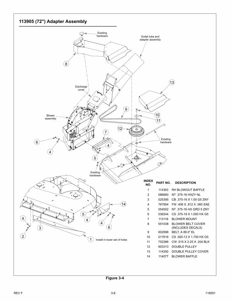
3. Release the deck drive belt tension. 54"/60" decks only – Remove the existing spindle boltand pulley from the center blade spindle.66"/72" decks only – Remove the existing spindle boltand pulley from the right side blade spindle. All decks – Replace the pulley with the double pulleyand place the new cup washer between the head of thenew bolt and the drive pulley. Thread the cup washer andbolt assembly into the spindle shaft. Torque bolt to 118ft.-lbs. Refer to Figure 3-1, Figure 3-2, Figure 3-3, orFigure 3-4.
4. Attach the deck blowout baffle to the underneath side ofthe deck. Refer to Figure 3-1, Figure 3-2, Figure 3-3, orFigure 3-4.NOTE: This baffle replaces the existing right side adjust-able baffle provided with the deck.NOTE: The blowout baffle is most useful in dry, dustyconditions, particularly when picking up leaves. In otherconditions, the adjustable baffle, supplied with the deck,may provide better cut quality and dispersion than theblowout baffle.
5. Attach the blower baffle to the deck. Refer to Figure 3-1,Figure 3-2, Figure 3-3, or Figure 3-4.
6. Assemble the blower mount to blower assembly. Refer toFigure 3-1, Figure 3-2, Figure 3-3, or Figure 3-4.
7. Attach the blower assembly to the deck by inserting therod through the discharge chute bracket and blowermount and secure with nut. Refer to Figure 3-1,Figure 3-2, Figure 3-3, or Figure 3-4.
8. Place the deck drive belt around the lower pulley of thedouble pulley. Confirm that the belt is properly routedand seated on all pulleys and idlers. Re-tension the deckdrive belt per the tensioning instructions found in themower’s General Service Manual.
Part No. Description Qty
N/A CATCHER FRAME 1
N/A WEIGHT MOUNT 1
N/A CATCHER BAG 3
N/A FRAME MOUNT 1
N/A BLOWER 1
113781 RH CATCHER MOUNT 1
113782 LH CATCHER MOUNT 1
114259 LH BAG GUARD 1
118608 RH BAG GUARD 1
604577 MUFFLER EXT 1.375" 1
604576 MUFFLER EXT 1.5" 1
025395 CB .375-16 X 1.00 G5 ZNY 2
074252 CS .500-13 X 1.50 HX G5 6
036236 CS 0.312-18 X 1.00 HX G5 4
036244 CS 0.375-16 X 1.00 HX G5 2
017616 CS 0.500-13 X 1.75 HX G5 6
768523 FW 0.343 SAE 8
767954 FW 0.406 SAE 10
078386 FW 0.510 X 1.75 X 0.18 2
767962 FW 0.531 SAE 20
034272 NT 0.312-18 HX G5 4
054502 NT 0.375-16 HX G5 2
086660 NT 0.375-16 NL G5 6
008193 NT 0.500-13 HX G5 8
769299 SC #10-24 X 0.75 BH 1
603340 UB .375-16 X 2.00 X 4.00 SQ 2
603356 FLEX TUBE 1
N/A INLET TUBE 1
Deck size Adapter Kit P/N
54" 121923
60" 113903
66" 113904
72" 113905

REV F 3-2 118551
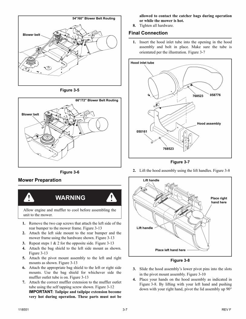
9. Install and route the blower belt around the blowerpulleys and the upper pulley on the double pulley. Thisbelt is self tensioning. Figure 3-5 or Figure 3-6
10. 54"/60" decks only – Remove the front right side decklift chain and attach the rigid link (115665) to the decklift arm. Position the center drive bracket (115773) on the deck asshown and attach it and the rigid link (115665) to thedeck.NOTE: The rigid link (115665) must move freely in thetop slot and rotate freely in the bottom hole.
11. Attach the blower belt cover. Refer to Figure 3-1,Figure 3-2, Figure 3-3, or Figure 3-4.
12. 66"/72" decks only – Attach the outlet adapter to theblower outlet tube. Refer to Figure 3-3 or Figure 3-4
WARNING
Do not operate deck without discharge chute or completecatcher system in place.

118551 3-3 REV F
Figure 3-1
1
2
3
4
7
8
11
13
4 12
121923 (54") Adapter Assembly
Blower assembly
Existing hardware
15
Discharge cover
Install in lower set of holes
16
4
10
14
3
Existing hardware
5
6
Existing hardware
Outlet tube and adapter assembly
9
Existing rod
INDEX NO.
PART NO. DESCRIPTION
1 553216 BLOWER BELT COVER (INCLUDES DECALS)
2 792002 KNOB 5/16-18 X 3/4"
3 036244 CS .375-16 X 1.00 HX G5
4 767954 FW .379 X .813 X .063
5 114194 BLOWER MOUNT
6 054502 NT .375-16 HX G5 ZNY
7 114389 54" BELT COVER BRACKET
8 601069 CN .312-18 X .20 MAX THK
9 603319 BELT, A 103.0" EL
10 017616 CS .500-13 X 1.75 HX G5
11 752386 CW .515 X 2.25 X .204 BLK
12 605832 DOUBLE DRIVE PULLEY
13 086660 NT .375-16 HX ZY NL
14 114360 RS 54" BLOWER BAFFLE
15 025395 CB .375-16 X 1.00 G5 ZNY
16 114071 54" BLOWER BAFFLE
6
4
4
Existing hardware
Existing hardware

REV F 3-4 118551
Figure 3-2
1
2
3
4
5
7
8
9
10
16
13
15
6
INDEX NO.
PART NO. DESCRIPTION
1 551305 BLOWER BELT COVER (INCLUDES DECALS)
2 603806 110.5" EL A-SEC BELT
3 114361 RS BLOWOUT BAFFLE
4 113118 BLOWER MOUNT
5 113127 BLOWER BAFFLE
6 792002 KNOB 5/16-18 X 3/4"
7 115665 RIGID LINK
8 115773 CENTER DRIVE BRACKET
9 602914 DOUBLE PULLEY
10 752386 CW .515 X 2.25 X .204 BLK
11 045765 FW 1.030 X 1.500 X .134 ZN
12 767954 FW .406 X .812 X .060 SAE
13 008573 CS .500-13 X 2.500 HX G5
14 036244 CS .375-16 X 1.000 HX G5
15 025395 CB .375-16 X 1.00 G5 ZNY
16 054502 NT .375-16 HX GRD 5 ZNY
17 086660 NT .375-16 HXZY NL
18 601069 CN .312-18 X .200 MAX THK
14
113903 (60") Adapter Assembly
12
Existing hardware
Blower assembly
Existing hardware
Existing hardware
Existing hardware
18
Discharge cover
Install in lower set of holes
12
12
12
12
17 14
Existing hardware
Existing hardware
7
16
Existing hardware
Outlet tube and adapter assembly
11
Existing rod

118551 3-5 REV F
Figure 3-3
13
4
4
4
4 4
5
5
6
6
7
9 10
11
12
14
1
32
8
INDEXNO.
PART NO. DESCRIPTION
1 114362 RH BLOWOUT BAFFLE
2 086660 NT .375-16 HXZY NL
3 025395 CB .375-16 X 1.00 G5 ZNY
4 767954 FW .406 X .812 X .060 SAE
5 054502 NT .375-16 HX GRD 5 ZNY
6 036244 CS .375-16 X 1.000 HX G5
7 113118 BLOWER MOUNT
8 551037 BLOWER BELT COVER (INCLUDES DECALS)
9 602997 BELT, A 86.0" EL
10 017616 CS .500-13 X 1.750 HX G5
11 752386 CW .515 X 2.25 X .204 BLK
12 603312 DOUBLE PULLEY
13 114349 DOUBLE PULLEY COVER
14 114074 BLOWER BAFFLE
113904 (66") Adapter Assembly
Existing hardware
Blower assembly
Existing hardware
Existing hardware
Discharge cover
Install in lower set of holes
Outlet tube and adapter assembly
REV F 3-6 118551
Figure 3-4
4
4
4
44
5
5
6
6
7
9
10
11
12
13
14
2
8
INDEXNO.
PART NO. DESCRIPTION
1 114363 RH BLOWOUT BAFFLE
2 086660 NT .375-16 HXZY NL
3 025395 CB .375-16 X 1.00 G5 ZNY
4 767954 FW .406 X .812 X .060 SAE
5 054502 NT .375-16 HX GRD 5 ZNY
6 036244 CS .375-16 X 1.000 HX G5
7 113118 BLOWER MOUNT
8 551038 BLOWER BELT COVER (INCLUDES DECALS)
9 602998 BELT, A 89.0" EL
10 017616 CS .500-13 X 1.750 HX G5
11 752386 CW .515 X 2.25 X .204 BLK
12 603313 DOUBLE PULLEY
13 114350 DOUBLE PULLEY COVER
14 114077 BLOWER BAFFLE
1
113905 (72") Adapter Assembly
3
Existing hardware
Blower assembly
Existing hardware
Existing hardware
Discharge cover
Install in lower set of holes
Outlet tube and adapter assembly
118551 3-7 REV F
Mower Preparation
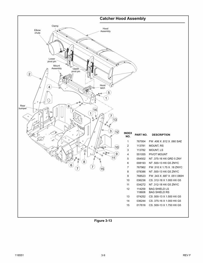
1. Remove the two cap screws that attach the left side of therear bumper to the mower frame. Figure 3-13
2. Attach the left side mount to the rear bumper and themower frame using the hardware shown. Figure 3-13
3. Repeat steps 1 & 2 for the opposite side. Figure 3-134. Attach the bag shield to the left side mount as shown.
Figure 3-13 5. Attach the pivot mount assembly to the left and right
mounts as shown. Figure 3-136. Attach the appropriate bag shield to the left or right side
mounts. Use the bag shield for whichever side themuffler outlet tube is on. Figure 3-13
7. Attach the correct muffler extension to the muffler outlettube using the self tapping screw shown. Figure 3-12IMPORTANT: Tailpipe and tailpipe extension becomevery hot during operation. These parts must not be
allowed to contact the catcher bags during operationor while the mower is hot.
8. Tighten all hardware.
Final Connection
1. Insert the hood inlet tube into the opening in the hoodassembly and bolt in place. Make sure the tube isorientated per the illustration. Figure 3-7
2. Lift the hood assembly using the lift handles. Figure 3-8
3. Slide the hood assembly’s lower pivot pins into the slotsin the pivot mount assembly. Figure 3-10
4. Place your hands on the hood assembly as indicated inFigure 3-8. By lifting with your left hand and pushingdown with your right hand, pivot the lid assembly up 90°
Figure 3-5
Figure 3-6
WARNING
Allow engine and muffler to cool before assembling theunit to the mower.
54"/60" Blower Belt Routing
Blower belt
66"/72" Blower Belt Routing
Blower belt
Figure 3-7
Figure 3-8
Hood inlet tube
Hood assembly
058776768523
768523
050161
Lift handle
Lift handle
Place left hand here
Place right hand here

REV F 3-8 118551
and over until the upper pins latch in the upper hoodlatch. Figure 3-10
5. Raise the discharge cover on the blower housing. Slidethe outlet adapter into place on the blower outlet. Securein place with the discharge cover latching the rod handleof the outlet adapter. Refer to Figure 3-1, Figure 3-2,Figure 3-3, or Figure 3-4.
6. Slide one end of the flex tube onto the blower outlet tube.Figure 3-11
7. Slide the other end of the flex tube over the catcher hoodelbow chute and secure in place with the clamp.Figure 3-11
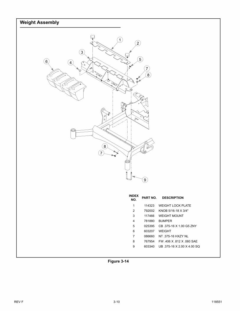
8. Attach the counter weight mount to the front of themower. Figure 3-14
9. Slide the weights vertically onto the mount and lock inplace using the weight lock plate and tighten knobs.Figure 3-14
10. Place the bags in the catcher assembly and close thecatcher hood. Make sure the catcher lid latches in place.NOTE: Make sure that the non-mesh side of the bag istowards the engine.
11. Reconnect the negative battery cable. 12. Increase the mower’s drive tire’s pressure to 16 psi (110
KPa). The drive tires will need to have to the air pressureincreased to support the additional weight of the catchersystem and when grass clippings are in the bags.NOTE: When the catcher system is removed the air pres-sure in the tires should be decreased to the normal operat-ing range of 8 - 12 psi (55 - 83 KPa).
Figure 3-9
Figure 3-10
Slot
Pin
Latch
Pin
Figure 3-11
Figure 3-12
Blower outlet tube
Catcher lid elbow chute
Clamp
Flex tube
Non-mesh side of bag
Index No.
Part No. DESCRIPTION
1 769299 SC #10 X.750 PHILLIPS
2 604576604577
MUFFLER EXT. 1.5" I.D.MUFFLER EXT. 1.375" I.D.
1
2
118551 3-9 REV F
Figure 3-13
INDEXNO.
PART NO. DESCRIPTION
1 767954 FW .406 X .812 X .060 SAE
2 113781 MOUNT, RS
3 113782 MOUNT, LS
4 551055 PIVOT MOUNT
5 054502 NT .375-16 HX GRD 5 ZNY
6 008193 NT .500-13 HX G5 ZNYC
7 767962 FW .510 X 1.75 X .18 ZNYC
8 078386 NT .500-13 HX G5 ZNYC
9 768523 FW .343 X .687 X .051/.080H
10 036236 CS .312-18 X 1.000 HX G5
11 034272 NT .312-18 HX G5 ZNYC
12 114259118608
BAG SHIELD LSBAG SHIELD RS
13 074252 CS .500-13 X 1.500 HX G5
14 036244 CS .375-16 X 1.000 HX G5
15 017616 CS .500-13 X 1.750 HX G5
Hood Assembly
76
67
11
Mount Assembly
2
1
15
7
12
5
9
10
13
3
7
8
114
4
Lower pivot pin
Upper pivot pin
Hood latch
Clamp
Elbow chute
Catcher Hood Assembly
Rear bumper
REV F 3-10 118551
Figure 3-14
2
3
6
8
7
1
9
7
8
45
INDEXNO.
PART NO. DESCRIPTION
1 114323 WEIGHT LOCK PLATE
2 792002 KNOB 5/16-18 X 3/4"
3 117466 WEIGHT MOUNT
4 781880 BUMPER
5 025395 CB .375-16 X 1.00 G5 ZNY
6 603207 WEIGHT
7 086660 NT .375-16 HXZY NL
8 767954 FW .406 X .812 X .060 SAE
9 603340 UB .375-16 X 2.00 X 4.00 SQ
Weight Assembly

118551 4-1 REV F
OPERATION
Vacuum Pickup and Collection
Follow normal mower start-up and operating procedures asoutlined in the mower operator’s manual. The blower willoperate when the mower deck clutch switch is engaged. To stopthe blower, return the deck clutch switch to the disengagedposition.
Proceed to mow in the normal manner and occasionallyglance at the flex tube. When the bags are full the speed ofdebris through the tube will decrease. When the bags are filled,move the deck clutch switch to the disengaged position anddrive the machine to the unloading area.
It is best that the bags be unloaded before the discharge chuteand flex tube areas become clogged. If clogging occurs, it willbe necessary to clear the blower chute and flex tube areas of allmaterial before starting to mow again.
Unloading the Catcher
Get off the mower and unlatch the rubber draw latches. Raisethe catcher lid, remove the bags and dump them. Figure 4-1
Return the bags to the catcher assembly, making sure that thenon-mesh side of the bag is towards the engine and close thecatcher lid. Make sure the catcher lid is latched. Figure 4-1.
Converting To Side Discharge Mode
Included with the catcher is a tall pulley cover. This is usedwhen converting from catcher mode to side discharge mode.
To convert:1. Park the mower on a flat surface. Turn engine off, place
the steering control levers in the park brake position andremove the ignition key. Be sure blades have stoppedbefore dismounting from the mower.
2. Remove the flex tube from the catcher lid elbow chuteand blower outlet tube. Figure 4-2
3. Remove the blower outlet tube from the blowerassembly. Figure 4-2
4. Remove the blower belt cover from the deck. Figure 4-25. Release the tension from the blower drive belt and
remove it. Figure 4-3 & Figure 4-4
WARNING
Make certain the engine is turned off, the steering controllevers are in the park brake position and the ignition keyis removed from the ignition switch and be sure bladeshave stopped before clearing the blower chute and flextube areas.
WARNING
Never place hands or feet into the discharge area. Theimpeller is relatively close to the housing and will causesevere injury. Use a probe to clean debris from blowerhousing discharge area. The discharge cover must remainclosed whenever the blower chute is removed.
WARNING
Never engage mower deck unless catcher flex tube isclamped in place on catcher lid elbow chute and insertedonto blower chute outlet tube.
WARNING
Prevent objects being thrown and the accumulation ofgrass clippings and other debris in engine compart-ment by NEVER operating mower deck unless:
• All bags are installed.• Hood is lowered and latched.• Flex tube is in place on the blower chute and on
the catcher lid elbow chute and clamped.
WARNING
Park the unit on a level surface, disengage the deck clutchswitch, place the steering control levers in the park brakeposition and shut the engine off. Remove the ignition key.Make certain the deck clutch switch is in the disengagedposition before unloading.
Figure 4-1
Non-mesh side
Catcher lidRubber
draw latch

REV F 4-2 118551
NOTE: It is not necessary to remove the double pulleyon the deck spindle.
6. Remove the pin that connects the blower to the dischargechute bracket tabs and remove the blower housing.Figure 4-3 & Figure 4-4
7. Assemble the torsion spring, original discharge chute andpin to the bracket tabs. Make sure the torsion spring isassembled as shown so that it applies pressure to thedischarge chute and keeps it in the down position.Figure 4-5
8. Remove the blower baffle and relace it with the right sideadjustable baffle that was provided with the deck.Figure 3-1, Figure 3-2, Figure 3-3 & Figure 3-4
9. 66” & 72” decks only – Assemble the tall pulley cover(included with the adapter kit) to the deck. Figure 4-5
10. Remove the bags and lid assembly from the rear of themachine.NOTE: It is not necessary to remove the catcher framethat is attached to the rear of the mower.
Removing the Lid Assembly
Use the following procedure when removing the lid assemblyfrom the mower.
1. Lift the lid assembly slightly and push the release lever to
release the latches. Figure 4-6 & Figure 4-72. Allow the lid assembly to pivot down.3. Using the lift handles lift the lid assembly out of the
notches on the mount assembly. Figure 4-7
WARNING
Always operate with complete catcher system, mulchingsystem or side discharge chute in place and in the lowestposition.
WARNING
Never operate the mower deck with side deflector dam-aged, altered, removed or in raised position, except whenthe entire grass catcher attachment or mulching system isbeing used.
Figure 4-2
Blower outlet tube
Catcher lid elbow chute
Clamp
Flex tube
Blower belt cover
Figure 4-3
Figure 4-4
Figure 4-5
Blower belt
Double pulley
Pin
54"/60" Blower Belt Routing
66"/72" Blower Belt Routing
Blower belt
Double pulley
Pin
Tall pulley cover
Discharge chute
Pin
Torsion spring

118551 4-3 REV F
Figure 4-6
Figure 4-7
Push Release
lever
Lift hereLid assembly
Lift handle
Lift handle
Release lever

REV F 4-4 118551
118551 5-1 REV F
MAINTENANCE & STORAGE
Blower Housing and Transfer Tube Maintenance
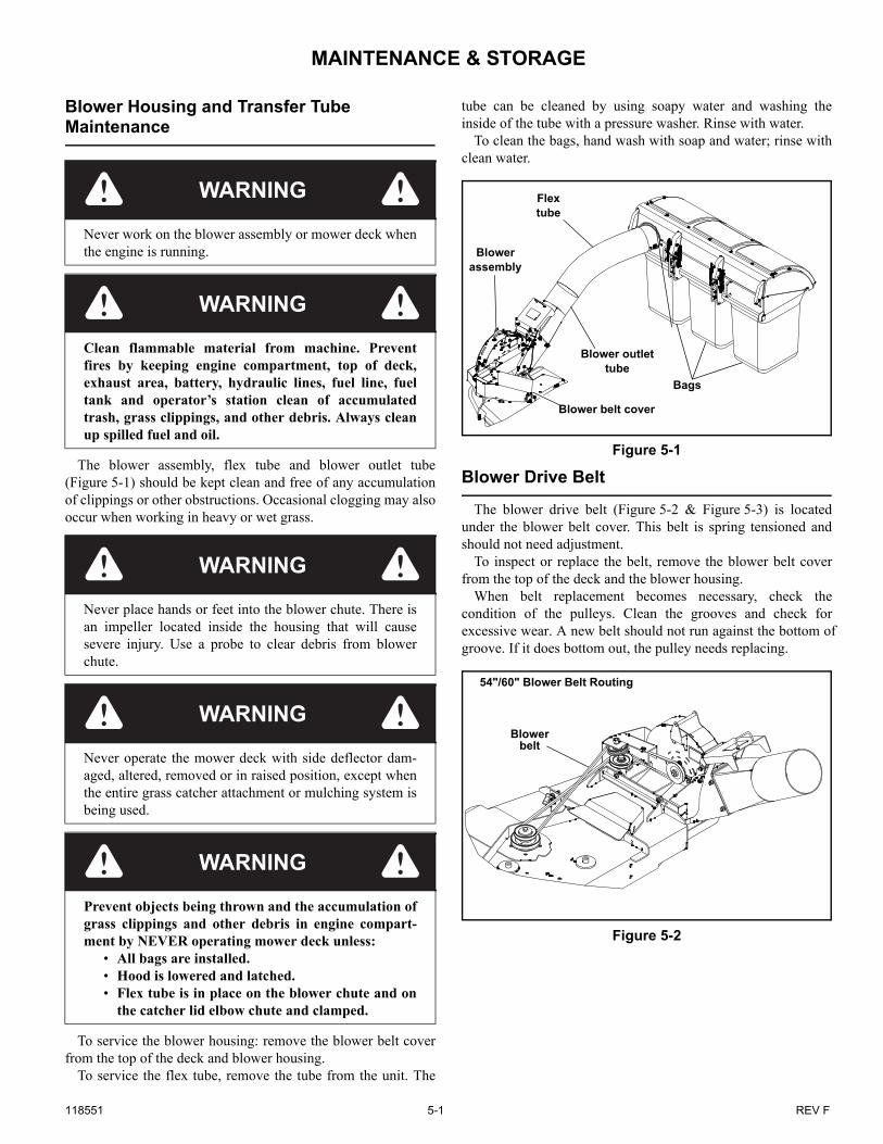
The blower assembly, flex tube and blower outlet tube(Figure 5-1) should be kept clean and free of any accumulationof clippings or other obstructions. Occasional clogging may alsooccur when working in heavy or wet grass.
To service the blower housing: remove the blower belt coverfrom the top of the deck and blower housing.
To service the flex tube, remove the tube from the unit. The
tube can be cleaned by using soapy water and washing theinside of the tube with a pressure washer. Rinse with water.
To clean the bags, hand wash with soap and water; rinse withclean water.
Blower Drive Belt
The blower drive belt (Figure 5-2 & Figure 5-3) is locatedunder the blower belt cover. This belt is spring tensioned andshould not need adjustment.
To inspect or replace the belt, remove the blower belt coverfrom the top of the deck and the blower housing.
When belt replacement becomes necessary, check the condition of the pulleys. Clean the grooves and check for excessive wear. A new belt should not run against the bottom of groove. If it does bottom out, the pulley needs replacing.
WARNING
Never work on the blower assembly or mower deck whenthe engine is running.
WARNING
Clean flammable material from machine. Preventfires by keeping engine compartment, top of deck,exhaust area, battery, hydraulic lines, fuel line, fueltank and operator’s station clean of accumulatedtrash, grass clippings, and other debris. Always cleanup spilled fuel and oil.
WARNING
Never place hands or feet into the blower chute. There isan impeller located inside the housing that will causesevere injury. Use a probe to clear debris from blowerchute.
WARNING
Never operate the mower deck with side deflector dam-aged, altered, removed or in raised position, except whenthe entire grass catcher attachment or mulching system isbeing used.
WARNING
Prevent objects being thrown and the accumulation ofgrass clippings and other debris in engine compart-ment by NEVER operating mower deck unless:
• All bags are installed.• Hood is lowered and latched.• Flex tube is in place on the blower chute and on
the catcher lid elbow chute and clamped.
Figure 5-1
Figure 5-2
Blower outlet tube
Blower belt cover
Bags
Flex tube
Blower assembly
Blower belt
54"/60" Blower Belt Routing
REV F 5-2 118551
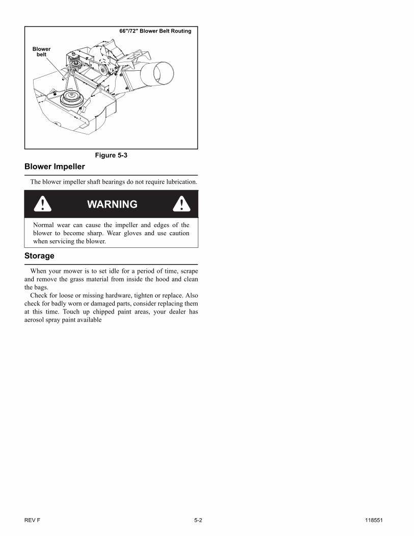
Blower Impeller
The blower impeller shaft bearings do not require lubrication.
Storage
When your mower is to set idle for a period of time, scrapeand remove the grass material from inside the hood and cleanthe bags.
Check for loose or missing hardware, tighten or replace. Alsocheck for badly worn or damaged parts, consider replacing themat this time. Touch up chipped paint areas, your dealer hasaerosol spray paint available
Figure 5-3
WARNING
Normal wear can cause the impeller and edges of theblower to become sharp. Wear gloves and use cautionwhen servicing the blower.
Blower belt
66"/72" Blower Belt Routing

118551 6-1 REV F
Parts List
54" Deck Adapter. . . . . . . . . . . . . . . . . . . . . . . . . . . . . . . . . . . . . . . . 6-2
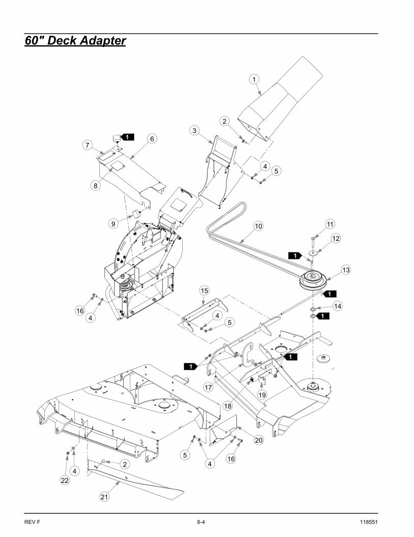
60" Deck Adapter. . . . . . . . . . . . . . . . . . . . . . . . . . . . . . . . . . . . . . . . 6-4
66" Deck Adapter. . . . . . . . . . . . . . . . . . . . . . . . . . . . . . . . . . . . . . . . 6-6
72" Deck Adapter. . . . . . . . . . . . . . . . . . . . . . . . . . . . . . . . . . . . . . . . 6-8
Blower—552623—S/N 14040001 & Higher. . . . . . . . . . . . . . . . . . . 6-10
Blower—550996—S/N Prior to 14040001. . . . . . . . . . . . . . . . . . . . 6-16
Catcher Frame—S/N 14040001 & Higher . . . . . . . . . . . . . . . . . . . . 6-20
Catcher Frame—S/N Prior to 14040001 . . . . . . . . . . . . . . . . . . . . . 6-24
Catcher Weight Mount . . . . . . . . . . . . . . . . . . . . . . . . . . . . . . . . . . . 6-28
Catcher Frame Adapter . . . . . . . . . . . . . . . . . . . . . . . . . . . . . . . . . . 6-30
Catcher Bag & Flex Tube . . . . . . . . . . . . . . . . . . . . . . . . . . . . . . . . 6-32

REV F 6-2 118551
54" Deck Adapter
3
1
2
5
8
7
6
13
4
10
14
15
16
8
8
9
10
11
12
20
19 810
18
1
7
1
1
6
817
19
1
1
1

118551 6-3 REV F
54" Deck Adapter
NOTES:
1. Use existing parts and hardware.
INDEX NO. PART NO. QTY. DESCRIPTION
1 603213 1 BLOWER OUTLET TUBE
2 114066 1 OUTLET ADAPTER
3 601837 1 DECK DANGERS DECAL
4 601624 1 DISCHARGE CHUTE DECAL
5 553216 1 BLOWER BELT COVER (WITH DECALS)
6 792002 1 KNOB 5/16-18 X 3/4"
7 036244 3 CS .375-16 X 1.00 HX G5
8 767954 14 FW .379 X .813 X .063
9 114194 1 BLOWER MOUNT
10 054502 7 NT .375-16 HX G5 ZNY
11 114389 1 54" BELT COVER BRACKET
12 601069 1 CN .312-18 X .20 MAX THK
13 603319 1 BELT, A 103.0" EL
14 017616 1 CS .500-13 X 1.75 HX G5
15 752386 1 CW .515 X 2.25 X .204 BLK
16 605832 1 DOUBLE DRIVE PULLEY
17 086660 4 NT .375-16 HX ZY NL
18 114360 1 RS 54" BLOWER BAFFLE
19 025395 6 CB .375-16 X 1.00 G5 ZNY
20 114071 1 54" BLOWER BAFFLE
REV F 6-4 118551
60" Deck Adapter
3
1
2
8
4
1614
6
10
7
5
11
12
13
4 4
15
5
18
17
21
19
2 45 16
224
1
1
1
20
1
1
9
1

118551 6-5 REV F
60" Deck Adapter
NOTES:
1. Use existing parts and hardware.
INDEX NO. PART NO. QTY. DESCRIPTION
1 603324 1 BLOWER OUTLET TUBE
2 025395 7 CB .375-16 X 1.00 G5 ZNY
3 114066 1 OUTLET ADAPTER
4 767954 13 FW .406 X .812 X .060 SAE
5 054502 7 NT .375-16 HX GRD 5 ZNY
6 551305 1 CENTER DRIVE COVER (WITH DECALS)
7 601624 1 DISCHARGE CHUTE DECAL
8 601837 1 DECK DANGERS DECAL
9 792002 1 KNOB 5/16-18 X 3/4"
10 603806 1 110.5" EL A-SEC BELT
11 008573 1 CS .500-13 X 2.500 HX G5
12 752386 1 CW .515 X 2.25 X .204 BLK
13 602914 1 DOUBLE PULLEY
14 045765 1 FW 1.030 X 1.500 X .134 ZN
15 113118 1 BLOWER MOUNT
16 036244 3 CS .375-16 X 1.000 HX G5
17 115665 1 RIGID LINK
18 601069 1 CN .312-18 X .200 MAX THK
19 115773 1 CENTER DRIVE BRACKET
20 113127 1 BLOWER BAFFLE
21 114361 1 RS BLOWOUT BAFFLE
22 086660 3 NT .375-16 HXZY NL

REV F 6-6 118551
66" Deck Adapter
1
6
8
4
5
7
9
1011
12
13
14
67
156
176
615
18
5
2
3
16
1
1
76
1
1

118551 6-7 REV F
66" Deck Adapter
NOTES:
1. Use existing parts and hardware.
INDEX NO. PART NO. QTY. DESCRIPTION
1 551037 1 66" BELT COVER W/ DECALS
2 601624 1 DISCHARGE CHUTE DECAL
3 601837 1 DECK DANGERS DECAL
4 603324 1 BLOWER OUTLET TUBE
5 025395 7 CB .375-16 X 1.00 G5 ZNY
6 767954 13 FW .406 X .812 X .060 SAE
7 054502 7 NT .375-16 HX GRD 5 ZNY
8 114066 1 OUTLET ADAPTER
9 114349 1 66" DBL PULLEY COVER
10 017616 1 CS .500-13 X 1.750 HX G5
11 752386 1 CW .515 X 2.25 X .204 BLK
12 602997 1 BELT, A 86.0" EL
13 603312 1 66" DOUBLE DRIVE
14 113118 1 BLOWER MOUNT
15 036244 3 CS .375-16 X 1.000 HX G5
16 114074 1 66" BLOWER BAFFLE
17 086660 3 NT .375-16 HXZY NL
18 114362 1 RS 66" BLOWOUT BAFFLE
REV F 6-8 118551
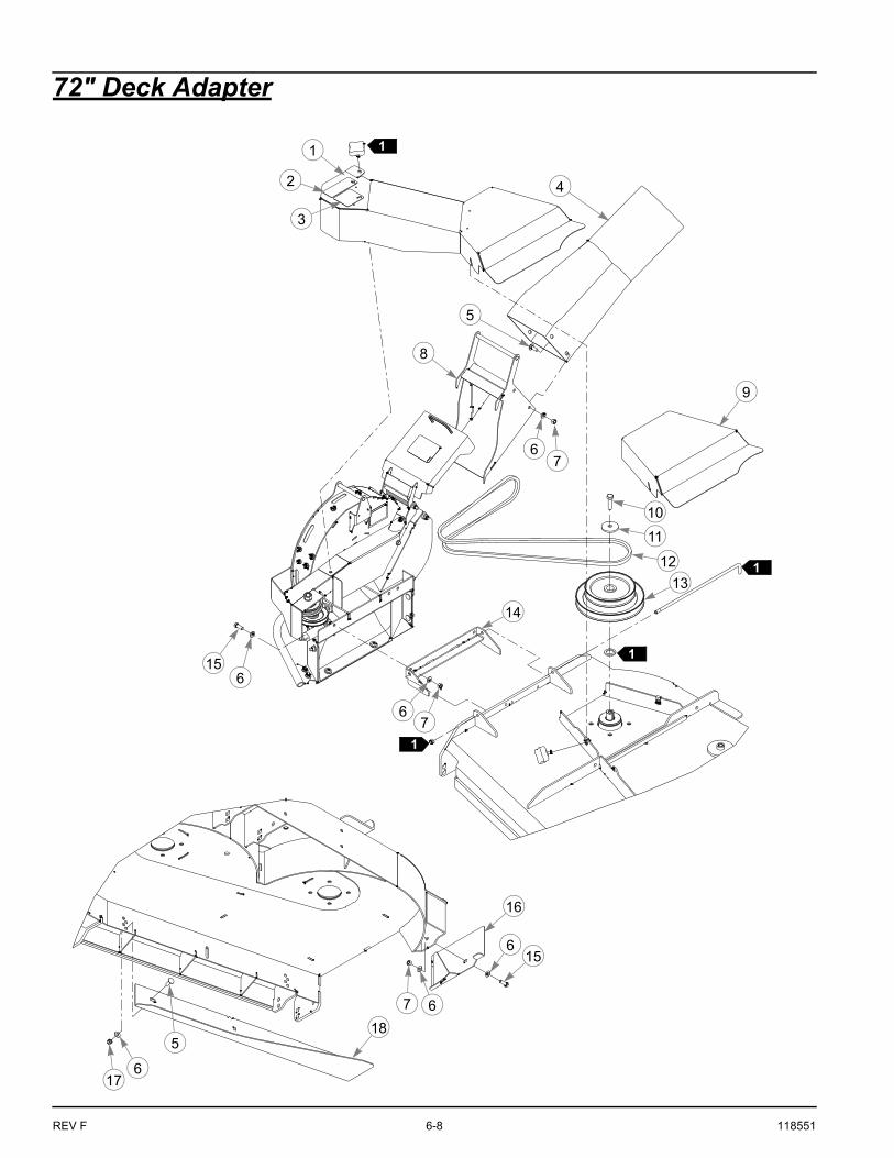
72" Deck Adapter
1
6
8
4
5
7
9
10
11
12
13
14
67
156
176
615
185
2
3
16
1
1
7 6
1
1
118551 6-9 REV F
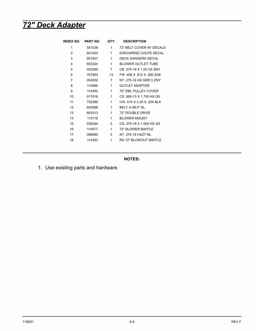
72" Deck Adapter
NOTES:
1. Use existing parts and hardware.
INDEX NO. PART NO. QTY. DESCRIPTION
1 551038 1 72" BELT COVER W/ DECALS
2 601624 1 DISCHARGE CHUTE DECAL
3 601837 1 DECK DANGERS DECAL
4 603324 1 BLOWER OUTLET TUBE
5 025395 7 CB .375-16 X 1.00 G5 ZNY
6 767954 13 FW .406 X .812 X .060 SAE
7 054502 7 NT .375-16 HX GRD 5 ZNY
8 114066 1 OUTLET ADAPTER
9 114350 1 72" DBL PULLEY COVER
10 017616 1 CS .500-13 X 1.750 HX G5
11 752386 1 CW .515 X 2.25 X .204 BLK
12 602998 1 BELT, A 89.0" EL
13 603313 1 72" DOUBLE DRIVE
14 113118 1 BLOWER MOUNT
15 036244 3 CS .375-16 X 1.000 HX G5
16 114077 1 72" BLOWER BAFFLE
17 086660 3 NT .375-16 HXZY NL
18 114363 1 RS 72" BLOWOUT BAFFLE
REV F 6-10 118551
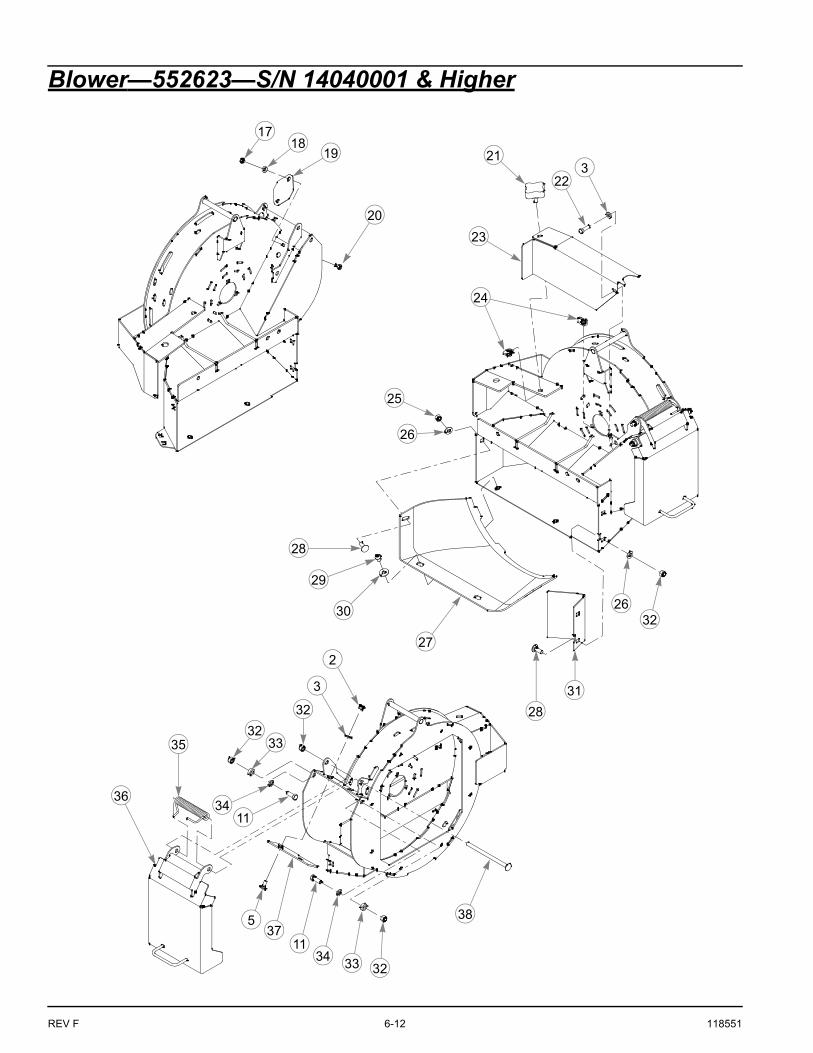
Blower—552623—S/N 14040001 & Higher
1
5
2
3
2
3
2
3
23
23
4
6
13
8
9
10
11
122
3
5
23
32
5
5
5
5
7
148
32
15
2
3
16
118551 6-11 REV F
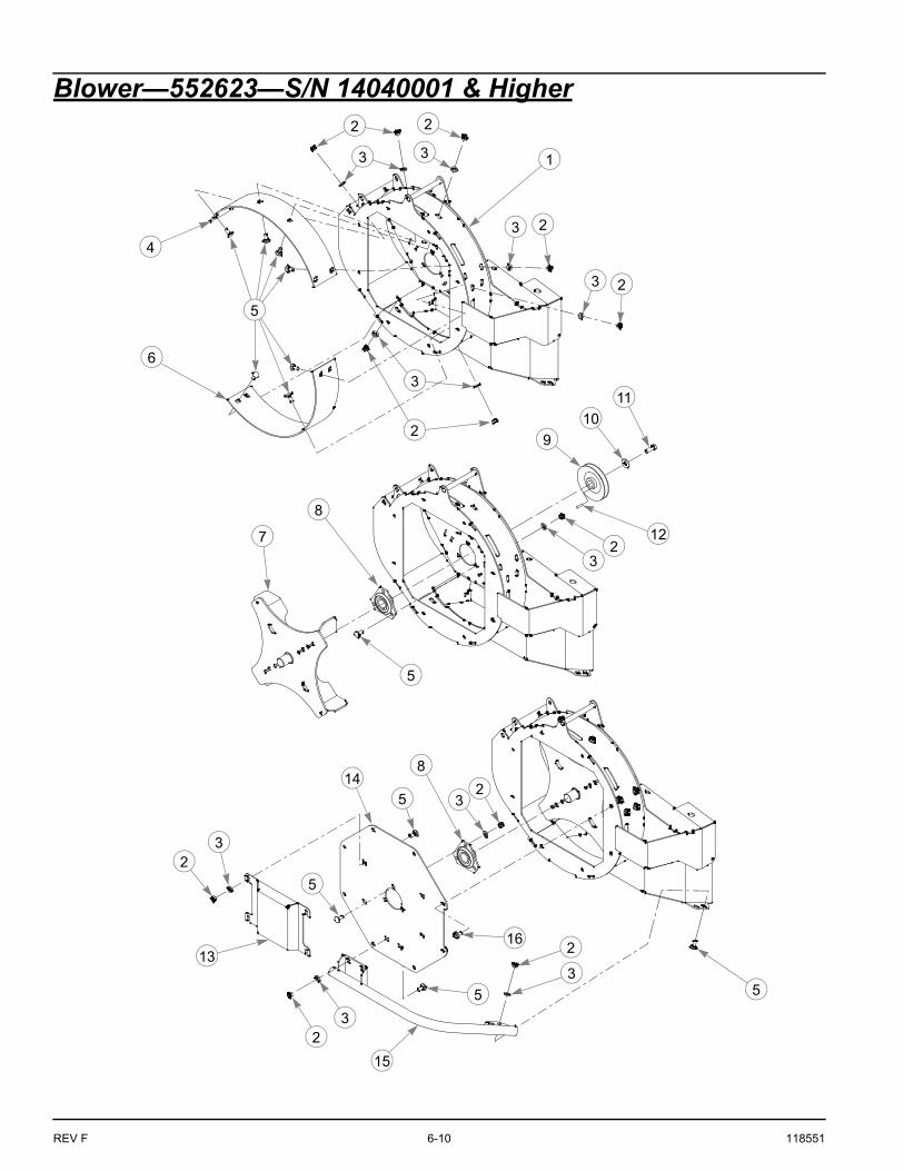
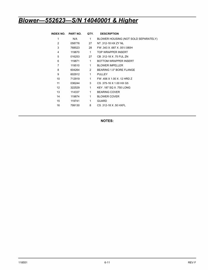
Blower—552623—S/N 14040001 & Higher
NOTES:
INDEX NO. PART NO. QTY. DESCRIPTION
1 N/A 1 BLOWER HOUSING (NOT SOLD SEPARATELY)
2 058776 27 NT .312-18 HX ZY NL
3 768523 28 FW .343 X .687 X .051/.080H
4 119870 1 TOP WRAPPER INSERT
5 016253 27 CB .312-18 X .75 FUL ZN
6 119871 1 BOTTOM WRAPPER INSERT
7 119510 1 BLOWER IMPELLER
8 604264 2 BEARING 1.0" BORE FLANGE
9 602912 1 PULLEY
10 712919 1 FW .406 X 1.00 X .12 HRD Z
11 036244 3 CS .375-16 X 1.00 HX G5
12 322529 1 KEY .187 SQ X .750 LONG
13 114337 1 BEARING COVER
14 119874 1 BLOWER COVER
15 119741 1 GUARD
16 799130 8 CS .312-18 X .50 HXFL
REV F 6-12 118551
Blower—552623—S/N 14040001 & Higher
2118
19
20
17
223
23
24
25
26
28
27
29
30
28
31
2632
2
3
32
3233
3411
35
36
537
1134
33 32
38

118551 6-13 REV F
Blower—552623—S/N 14040001 & Higher
NOTES:
INDEX NO. PART NO. QTY. DESCRIPTION
17 068551 2 NT .250-20 HX ZY NL
18 768515 2 FW .281 X .625 X .066
19 120615 1 COVER PLATE
20 794784 2 CB .250-20 X .75 FUL ZN
21 792002 1 KNOB 5/16-18 X 3/4"
22 036236 1 CS .312-18 X 1.00 HX G5
23 120266 1 PULLEY COVER
24 601069 2 CN .312-18 X .20 MAX THK
25 054502 1 NT .375-16 HX G5 ZNY
26 767954 3 FW .379 X .813 X .063
27 603191 1 BLOWER CHUTE INLET
28 025395 3 CB .375-16 X 1.00 G5 ZNY
29 774919 2 CS .375-16 X .50 SOC BH
30 076422 2 FW .406 X 1.00 X .06 ZNYC
31 113128 1 BLOWER INLET BAFFLE
32 086660 5 NT .375-16 HX ZY NL
33 073858 2 FW .406 X .75 X .25 ZNYC
34 704718 2 FW .406 X .688 X .060 ZNYC
35 602435 1 TORSION SPRING
36 550995 1 BLOWER LID (WITH DECALS)
37 119872 1 ABRASION GUARD
38 602674 1 CB .375-16 X 6.00 STD

REV F 6-14 118551
Blower—552623—S/N 14040001 & Higher
40
41
42
43
4152
53
54
44
45
46
47
48
49
46
45
50
42
41
51
39
41
43
39
55

118551 6-15 REV F
Blower—552623—S/N 14040001 & Higher
NOTES:
INDEX NO. PART NO. QTY. DESCRIPTION
39 600296 3 DECK IDLER SPACER
40 791566 1 IDLER PULLEY 3.25" OD X .6
41 028118 4 FW .625 X 1.00 X .134 ZNYC
42 016642 2 CS .625-11 X 2.00 HX G5 Z
43 016972 2 NT .625-11 HX G5 ZNYC
44 781567 1 NT .500-13 HX G8 ZY NL
45 767962 2 FW .531 X 1.063 X .175
46 770867 2 BUSHING
47 109549 1 BUSHING
48 036384 1 SPRING 1/4 COIL PL 1.23
49 113406 1 BLOWER IDLER ARM
50 008573 1 CS .500-13 X 2.50 HX G5
51 602913 1 V-IDLER PULLEY
52 602757 1 BLOWER DANGERS DECAL
53 N/A 1 SERIAL NUMBER / SPEC DECAL
54 602758 1 EYES/EARS/FOOT DECAL
55 552623 1 BLOWER ASSEMBLY

REV F 6-16 118551
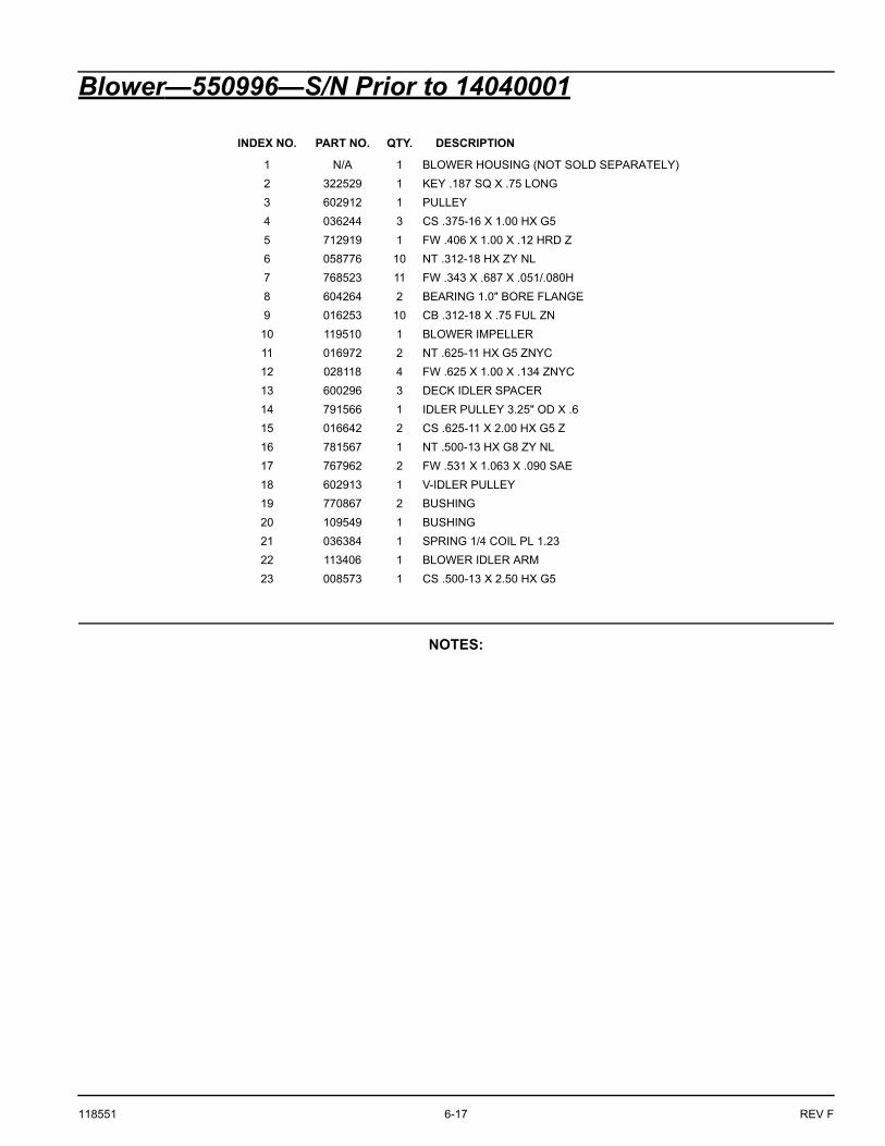
Blower—550996—S/N Prior to 14040001
4
5
321
67
10 8
9
12
11
15
12
13
14
16
11
18
19
22
17
20
13
12
15
21
12
23
17
19
118551 6-17 REV F
Blower—550996—S/N Prior to 14040001
NOTES:
INDEX NO. PART NO. QTY. DESCRIPTION
1 N/A 1 BLOWER HOUSING (NOT SOLD SEPARATELY)
2 322529 1 KEY .187 SQ X .75 LONG
3 602912 1 PULLEY
4 036244 3 CS .375-16 X 1.00 HX G5
5 712919 1 FW .406 X 1.00 X .12 HRD Z
6 058776 10 NT .312-18 HX ZY NL
7 768523 11 FW .343 X .687 X .051/.080H
8 604264 2 BEARING 1.0" BORE FLANGE
9 016253 10 CB .312-18 X .75 FUL ZN
10 119510 1 BLOWER IMPELLER
11 016972 2 NT .625-11 HX G5 ZNYC
12 028118 4 FW .625 X 1.00 X .134 ZNYC
13 600296 3 DECK IDLER SPACER
14 791566 1 IDLER PULLEY 3.25" OD X .6
15 016642 2 CS .625-11 X 2.00 HX G5 Z
16 781567 1 NT .500-13 HX G8 ZY NL
17 767962 2 FW .531 X 1.063 X .090 SAE
18 602913 1 V-IDLER PULLEY
19 770867 2 BUSHING
20 109549 1 BUSHING
21 036384 1 SPRING 1/4 COIL PL 1.23
22 113406 1 BLOWER IDLER ARM
23 008573 1 CS .500-13 X 2.50 HX G5

REV F 6-18 118551
Blower—550996—S/N Prior to 1404000124
76
268
930
29
277
28
34
35
313233
4 36
37
31
38
39
42
4643
40
31
41
42
44
40
25
47
45

118551 6-19 REV F
Blower—550996—S/N Prior to 14040001
NOTES:
INDEX NO. PART NO. QTY. DESCRIPTION
24 114337 1 BEARING COVER
25 113119 1 BLOWER COVER
26 799130 8 CS .312-18 X .50 HXFL
27 792002 1 KNOB 5/16-18 X 3/4"
28 036236 1 CS .312-18 X 1.00 HX G5
29 114338 1 DRIVEN PULLEY COVER
30 601069 2 CN .312-18 X .20 MAX THK
31 086660 5 NT .375-16 HX ZY NL
32 073858 2 FW .406 X .75 X .25 ZNYC
33 602674 1 CB .375-16 X 6.00 STD
34 602757 1 BLOWER DANGERS DECAL
35 N/A 1 SERIAL NO. / SPEC DECAL
36 704718 2 FW .406 X .688 X .060 ZNYC
37 602435 1 TORSION SPRING
38 550995 1 BLOWER LID (WITH DECALS)
39 602758 1 EYES/EARS/FOOT DECAL
40 767954 3 FW .406 X .812 X .060 SAE
41 603191 1 BLOWER CHUTE INLET
42 025395 3 CB .375-16 X 1.00 G5 ZNY
43 113128 1 BLOWER INLET BAFFLE
44 054502 1 NT .375-16 HX G5 ZNY
45 076422 2 FW .406 X 1.00 X .06 ZNYC
46 774919 2 CS .375-16 X .50 SOC BH
47 550996 1 BLOWER ASSEMBLY
REV F 6-20 118551
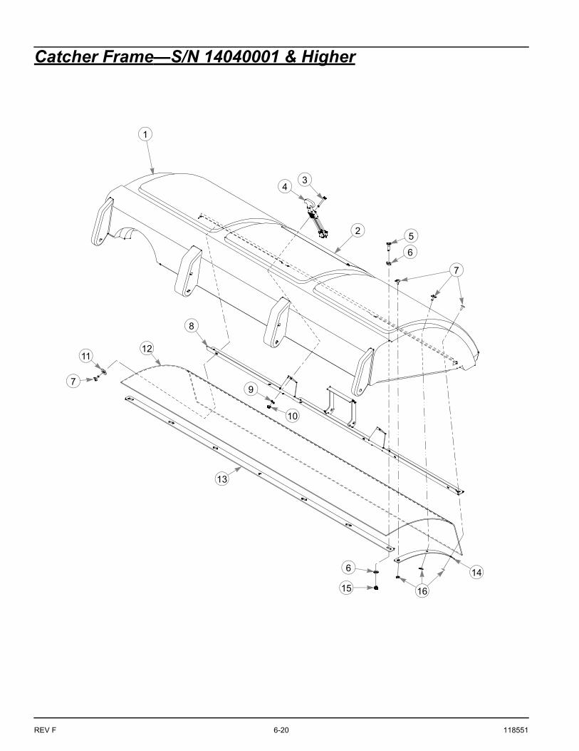
Catcher Frame—S/N 14040001 & Higher
1
3
2
15
6
4
7
6
8
5
9
14
13
7
11
10
16
12

118551 6-21 REV F
Catcher Frame—S/N 14040001 & Higher
NOTES:
INDEX NO. PART NO. QTY. DESCRIPTION
1 603225 1 LID
2 603419 1 CATCHER DECAL
3 080291 6 CS 10-24 X 1.50 HX ZNYC
4 603675 2 LATCH
5 056077 7 CS .250-20 X 1.00 HX G5
6 768515 14 FW .281 X .625 X .051/.080 HD ZN/YL
7 603398 20 RIVET
8 114399 1 LID INSERT
9 704932 6 FW .219 X .500 X .048 ZNYC
10 059832 7 NT #10-24 HX NL ZN
11 079210 6 FW .344 X 1.00 X .06 ZNYC
12 603353 1 SCREEN
13 115146 1 BACK RIB BRACKET
14 115147 2 SIDE RIB BRACKET
15 068551 7 NT .250-20 HX ZY NL
16 603400 8 FW .188 X .50 X .060

REV F 6-22 118551
Catcher Frame—S/N 14040001 & Higher
18
19
20
24
2632
2931 30
29
28
21
10
17
3
17
9
26
22
23
2535
26
10
38
3734
26
36
1718
17
18
18
4
27
33

118551 6-23 REV F
Catcher Frame—S/N 14040001 & Higher
NOTES:
INDEX NO. PART NO. QTY. DESCRIPTION
17 603678 8 CAP NUT
18 603332 8 CLIP
19 114249 2 SPRING LID PIN
20 603333 2 SB .375 X 1.25 SH .312-18
21 113640 1 3 BAG CATCHER FRAME
22 603285 4 LID HINGE SPRING
23 603418 1 LID SEAL
24 114248 2 LID HINGE PIN
25 120505 2 LATCH BRACKET
26 768523 12 FW .343 X .687 X .051/.080H
27 034280 4 CS .312-18 X .75 HX G5
28 036244 2 CS .375-16 X 1.00 HX G5
29 767954 4 FW .406 X .812 X .060 SAE
30 114118 1 LID ADJUST BRACKET
31 054502 2 NT .375-16 HX G5 ZNY
32 034272 2 NT .312-18 HX G5 ZNYC
33 N/A 1 SERIAL NUMBER / SPEC DECAL
34 058776 3 NT .312-18 HX ZY NL
35 050161 3 CS .312-18 X 1.75 HX G5
36 603214 1 INLET TUBE
37 060723 1 MS #10-24 X .50 TH SL
38 602830 1 SNAP FASTENER

REV F 6-24 118551
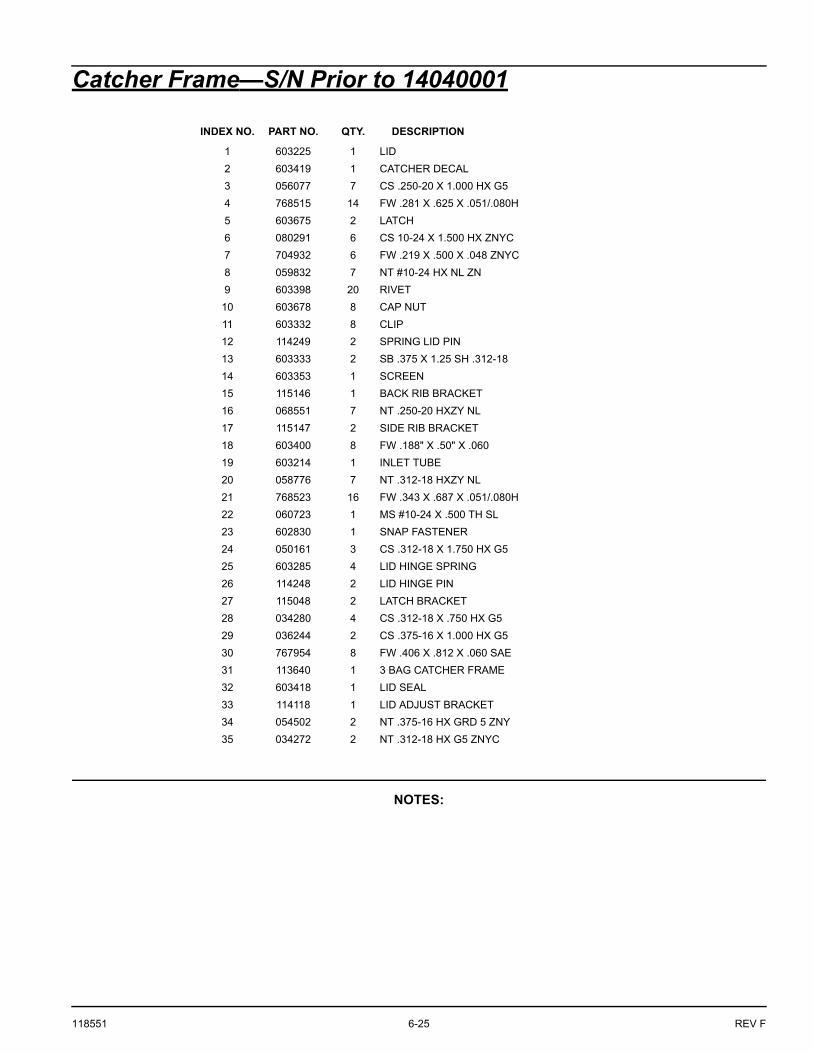
Catcher Frame—S/N Prior to 14040001
1
3
11
12
13
4
14
19
21
20
24
21
26 11
2135
3034 33
30
29
2
2223
8
3231
28
21 8
4
9
6
7
8
5
10
111015
6
1618
17
7
27
25
1010 115
118551 6-25 REV F
Catcher Frame—S/N Prior to 14040001
NOTES:
INDEX NO. PART NO. QTY. DESCRIPTION
1 603225 1 LID
2 603419 1 CATCHER DECAL
3 056077 7 CS .250-20 X 1.000 HX G5
4 768515 14 FW .281 X .625 X .051/.080H
5 603675 2 LATCH
6 080291 6 CS 10-24 X 1.500 HX ZNYC
7 704932 6 FW .219 X .500 X .048 ZNYC
8 059832 7 NT #10-24 HX NL ZN
9 603398 20 RIVET
10 603678 8 CAP NUT
11 603332 8 CLIP
12 114249 2 SPRING LID PIN
13 603333 2 SB .375 X 1.25 SH .312-18
14 603353 1 SCREEN
15 115146 1 BACK RIB BRACKET
16 068551 7 NT .250-20 HXZY NL
17 115147 2 SIDE RIB BRACKET
18 603400 8 FW .188" X .50" X .060
19 603214 1 INLET TUBE
20 058776 7 NT .312-18 HXZY NL
21 768523 16 FW .343 X .687 X .051/.080H
22 060723 1 MS #10-24 X .500 TH SL
23 602830 1 SNAP FASTENER
24 050161 3 CS .312-18 X 1.750 HX G5
25 603285 4 LID HINGE SPRING
26 114248 2 LID HINGE PIN
27 115048 2 LATCH BRACKET
28 034280 4 CS .312-18 X .750 HX G5
29 036244 2 CS .375-16 X 1.000 HX G5
30 767954 8 FW .406 X .812 X .060 SAE
31 113640 1 3 BAG CATCHER FRAME
32 603418 1 LID SEAL
33 114118 1 LID ADJUST BRACKET
34 054502 2 NT .375-16 HX GRD 5 ZNY
35 034272 2 NT .312-18 HX G5 ZNYC

REV F 6-26 118551
Catcher Frame—S/N Prior to 14040001
39
40
20
21
21
38
36
30
20
21
30
3737

118551 6-27 REV F
Catcher Frame—S/N Prior to 14040001
NOTES:
INDEX NO. PART NO. QTY. DESCRIPTION
36 603358 2 LID LATCH SPRING
37 063297 4 SB .375 X .500 SH .312-18
38 073858 1 FW .406 X .750 X .250 ZNYC
39 113794 1 LID CATCH
40 114399 1 LID INSERT

REV F 6-28 118551
Catcher Weight Mount
2
1
2
3
4
5
7
8
6
7
8
9
118551 6-29 REV F
Catcher Weight Mount
NOTES:
INDEX NO. PART NO. QTY DESCRIPTION
1 114323 1 WEIGHT LOCK PLATE
2 792002 2 KNOB 5/16-18 X 3/4"
3 025395 2 CB .375-16 X 1.00 G5 ZNY
4 117466 1 WEIGHT MOUNT
5 781880 8 BUMPER
6 603207 4 WEIGHT
7 086660 6 NT .375-16 NL G5
8 767954 6 FW .406 X .812 X .060 SAE
9 603340 2 UB .375-16 X 2.00 X 4.00 SQ
REV F 6-30 118551
Catcher Frame Adapter
1
23
32
4
5
46
8
5
910
7
6
109 12
114
13
14
17
18
1516
20
1619
1821
22
54
46
2318
24
1817
25
26 27
118551 6-31 REV F
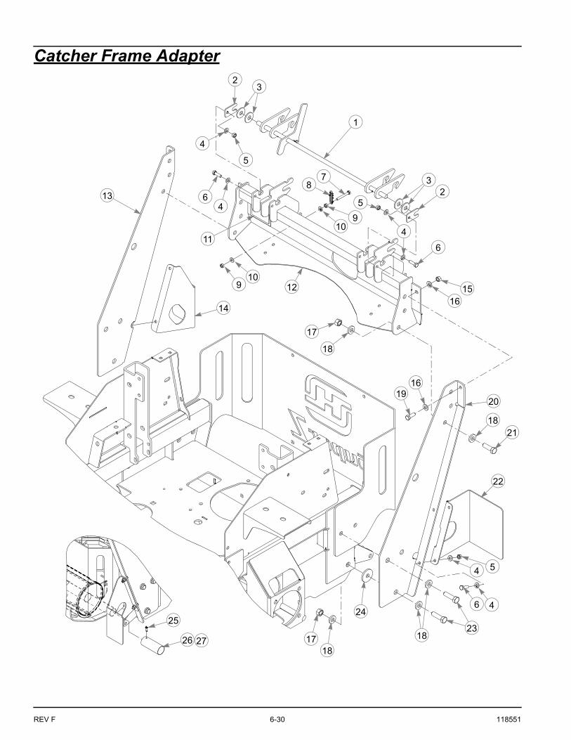
Catcher Frame Adapter
NOTES:
1. In the event the serial number decal becomes damaged or illegible, please contact your dealer to order a replacement.
INDEX NO. PART NO. QTY. DESCRIPTION
1 113965 1 LID MOUNT LATCH
2 113969 2 KEEPER LATCH
3 712976 4 FW .531 X 1.375 X .125 ZNY
4 768523 12 FW .343 X .687 X .051/.080H
5 034272 6 NT .312-18 HX G5 ZNYC
6 036236 6 CS .312-18 X 1.00 HX G5
7 704163 1 CS .250-20 X 2.00 HX G5 Z
8 603358 1 LID LATCH SPRING
9 024927 2 NT .250-20 HX G5 ZNYC
10 768515 2 FW .281 X .625 X .051/.080 HD ZN/YL
11 N/A 1 SERIAL NO. / SPEC DECAL
12 113773 1 PIVOT MOUNT
13 113781 1 RS CATCHER MOUNT
14 118608 1 RS BAG GUARD
15 054502 2 NT .375-16 HX G5 ZNY
16 767954 4 FW .406 X .812 X .060 SAE
17 008193 8 NT .500-13 HX G5 ZNYC
18 767962 20 FW .531 X 1.063 X .090 SAE
19 036244 2 CS .375-16 X 1.00 HX G5
20 113782 1 LS CATCHER MOUNT
21 074252 6 CS .500-13 X 1.50 HX G5
22 114259 1 LS BAG GUARD
23 017616 6 CS .500-13 X 1.75 HX G5
24 078386 2 FW .510 X 1.75 X .18 ZNYC
25 769299 1 SC #10 X .750 PHILLIPS T
26 604576 1 MUFFLER EXTENSION 1.5"
27 604577 1 MUFFLER EXTENSION 1.375"

REV F 6-32 118551
Catcher Bag & Flex Tube
INDEX NO. PART NO. QTY. DESCRIPTION
1 603127 3 CATCHER BAG ASSEMBLY (INCLUDES ITEMS 2–8)
2 603119 1 CATCHER BAG ROD
3 603120 1 ROD JOINING TUBE
4 058776 2 NT .312-18 HX NL G5
5 079210 2 FW .344 X 1.00 X .06 ZNYC
6 603122 1 CATCHER BAG HANDLE
7 037887 2 CB .312-18 X 1.00 FULL ZN
8 603677 1 COMPRESSION COUPLING
9 603356 1 8" CLEAR FLEX TUBE
2
3
45
45
6
7
8
9

118551 i-1 REV F
INDEXPAGE PAGE
Blower Drive Belt .............................................5-1
Blower Housing & Transfer Tube ...................5-1
Blower Impeller ................................................5-2
Catcher Hood Assembly..................................3-9
Converting To Side Discharge Mode .............4-1
Deck Adapter Kits ............................................3-1
Final Connection ..............................................3-7
Mower Deck Preparation.................................3-1
Mower Preparation ..........................................3-7
Packing List - 932467 Catcher........................3-1
Parts and Service ............................................1-1
Removing the Lid Assembly ...........................4-2
Safe Operation and Service Precautions .......2-1
Storage .............................................................5-2
To the New Owner ...........................................1-1
Unloading the Catcher .....................................4-1
Using This Manual ...........................................1-1
Vacuum Pickup and Collection .......................4-1
Warranty Registration ......................................1-1
Weight Assembly .............................................3-10
113903 Adapter Assembly ..............................3-4
113904 Adapter Assembly ..............................3-5
113905 Adapter Assembly ..............................3-6
121923 Adapter Assembly ..............................3-3