Hustler FasTrak Super Duty 36/42 & Mini Z 36/42 Parts Manual · 2017-10-24 · 108737 05/10 1-1...
98
••••••• Hustler Turf Equipment ••••• P.O. Box 7000 ••• Hesston, Kansas • 67062-2097 Hustler FasTrak Super Duty 36/42 & Mini Z 36/42 Parts Manual
Transcript of Hustler FasTrak Super Duty 36/42 & Mini Z 36/42 Parts Manual · 2017-10-24 · 108737 05/10 1-1...

•••••••Hustler Turf Equipment
•••••P.O. Box 7000
•••Hesston, Kansas
•67062-2097
Hustler FasTrak Super Duty 36/42& Mini Z 36/42 Parts Manual
t-2 108737 05/10
IMPORTANT: This engine is not equipped with a spark arrester muffler. It is a violation of California Public Resource Code Section 4442 to use or operate this engine on any forest-covered, brush-covered, or grass-covered unimproved land. Other states or federal areas may have similar laws.
This spark ignition system complies with Canadian ICES-002.
The Engine Owner’s Manual provides information regarding the U.S. Environmental Protection Agency (EPA) and the California Emission Control Regulation of emission systems, maintenance and warranty.
Keep Engine Owner’s Manual with your unit. Should the Engine Owner’s Manual become damaged or illegible, re-place immediately. Replacements may be ordered per the information found in the Product Information section of the owner’s manual.
The engine exhaust from this product contains chemicals known to the State
of California to cause cancer, birth defects or other reproductive harm.
WARNING:

108737 05/10 c-1
Table of Contents
Chapter 1 General Information . . . . . . . . . . . . . . . . . . . . . . . . . . . . . . . . . . . . 1-1
Chapter 2 Frame Rivet Nut Installation . . . . . . . . . . . . . . . . . . . . . . . . . . . . . . 2-2Anti-Rollover Bracket Assemblies . . . . . . . . . . . . . . . . . . . . . . . . . . 2-3Footrest Assembly . . . . . . . . . . . . . . . . . . . . . . . . . . . . . . . . . . . . . 2-4
Chapter 3 Battery Installation. . . . . . . . . . . . . . . . . . . . . . . . . . . . . . . . . . . . . . 3-2Deck Lift Assembly . . . . . . . . . . . . . . . . . . . . . . . . . . . . . . . . . . . . . 3-4Hydro Transmission Installation . . . . . . . . . . . . . . . . . . . . . . . . . . . 3-6Steering and Brake Assembly. . . . . . . . . . . . . . . . . . . . . . . . . . . . . 3-10
Chapter 4 Kawasaki Engine Installation . . . . . . . . . . . . . . . . . . . . . . . . . . . . . 4-2Fuel System Installation . . . . . . . . . . . . . . . . . . . . . . . . . . . . . . . . . 4-6Instrument Panel Installation. . . . . . . . . . . . . . . . . . . . . . . . . . . . . . 4-8Kawasaki Electrical Schematic (601218) . . . . . . . . . . . . . . . . . . . . 4-10
Chapter 5 Front Wheel Assembly . . . . . . . . . . . . . . . . . . . . . . . . . . . . . . . . . . 5-2Front Wheel Breakdown—786061 . . . . . . . . . . . . . . . . . . . . . . . . . 5-3Drive Wheel Assembly . . . . . . . . . . . . . . . . . . . . . . . . . . . . . . . . . . 5-4
Chapter 6 Deck Assembly 36" SN Prior to 10020000 . . . . . . . . . . . . . . . . . . . 6-2Deck Assembly 36" SN Higher Than 10020000 . . . . . . . . . . . . . . . 6-4Deck Pulley Assembly 36" . . . . . . . . . . . . . . . . . . . . . . . . . . . . . . . 6-6Deck Assembly 42" SN Prior to 10020000 . . . . . . . . . . . . . . . . . . . 6-8Deck Assembly 42" SN Higher Than 10020000 . . . . . . . . . . . . . . . 6-10Deck Pulley Assembly 42" . . . . . . . . . . . . . . . . . . . . . . . . . . . . . . . 6-12Spindle Assembly—783506 . . . . . . . . . . . . . . . . . . . . . . . . . . . . . . 6-14
Chapter 7 Deck Installation . . . . . . . . . . . . . . . . . . . . . . . . . . . . . . . . . . . . . . . 7-2Deck Belt Routing . . . . . . . . . . . . . . . . . . . . . . . . . . . . . . . . . . . . . . 7-3Seat Installation. . . . . . . . . . . . . . . . . . . . . . . . . . . . . . . . . . . . . . . . 7-4
Chapter 8 Tractor Decals. . . . . . . . . . . . . . . . . . . . . . . . . . . . . . . . . . . . . . . . . 8-236" Deck Decals . . . . . . . . . . . . . . . . . . . . . . . . . . . . . . . . . . . . . . . 8-442" Deck Decals . . . . . . . . . . . . . . . . . . . . . . . . . . . . . . . . . . . . . . . 8-5
Chapter 9 Assembly Pictures and Aids . . . . . . . . . . . . . . . . . . . . . . . . . . . . . . 9-2Maintenance & Adjustment Safety . . . . . . . . . . . . . . . . . . . . . . . . . 9-5Maintenance . . . . . . . . . . . . . . . . . . . . . . . . . . . . . . . . . . . . . . . . . . 9-9Adjustments . . . . . . . . . . . . . . . . . . . . . . . . . . . . . . . . . . . . . . . . . . 9-26
Index. . . . . . . . . . . . . . . . . . . . . . . . . . . . . . . . . . . . . . . . . . . . . . . . . . . . . . . . i-1

c-2 108737 05/10
108737 05/10 1-1
Chapter 1
General Information
This Manual covers Hustler FasTrak Super Duty and Mini Z models: 928192 & 928200 with serial numbers higher than 07020000.
Frequently Ordered Parts
Service Literature
Note: When ordering parts, you must use the part number as shown for each part, not the index number. Always give the model and serial number to your parts and service representative.
Note: Items sold in bulk such as seals and hoses are sold by the foot.
Using this manual
Illustrations used were current at the time of printing, but subsequent production changes may cause your machine to vary slightly in detail. Excel Industries, Inc. reserves the right to redesign and change the machine as deemed neces-sary, without notification. If a change has been made to your machine which is not reflected in this parts manual, see your Hustler dealer for current information and parts.
Options Available From Your Dealer
PART NO. DESCRIPTION788794 Pump Drive Belt600726 Deck Drive Belt, 36"600734 Deck Drive Belt, 42"068478 Fuel Filter797852 Air Filter Precleaner761726 Air Filter Element600976 ZT 2800 Oil Filter772079 Engine Oil Filter
PART NO. DESCRIPTION107708 Owner’s Manual797795 Kawasaki 17/19 HP Kai Engine Manual
PART NO. DESCRIPTION107654 Mulch Kit (36"/42" Deck)794222 Gator Blade, 13.75"-GAT-F-CW794230 Gator Blade, 20.50"-GAT-F-CW794206 Mulch Blade, 13.75"-MUL-F-CW794214 Mulch Blade, 20.50"-MUL-F-CW (60" Side Discharge Deck)353961 Steering Extension Kit107696 Hitch Kit
1-2 108737 05/10
Hardware Description Codes & Abbreviations
The following codes are used throughout this parts manual. Refer to this list when ordering parts.
Standard TorquesThe following chart lists the standard torque values for the threaded fasteners found in this manual. Torque all cap screws, nuts and set screws to these values unless a different torque is shown in the Notes section next to the fastener.
NOTE:Loctite® 592 to be used on all pipe threads.Lubricate all grease zerks.
ABBREVIATION DESCRIPTIONCB Carriage BoltCE Clevis PinCP Cotter PinCS Cap ScrewCW Cup Washer
FDRW Fender WasherFW Flat WasherHX Hex HeadLW Lock WasherMB Machine BushingMS Machine ScrewNT NutSC Self Tapping Cap ScrewSH Socket HeadSB Shoulder BoltSS Set ScrewOD Outside DiameterID Inside Diameter
SIZE FT-LBS NM SIZE FT-LBS NM.250 8.2 11.1 M3 1 1.3.312 17 23 M4 2.2 3.375 30 40 M5 4.5 6.1.438 48 65 M6 7.7 10.4.500 73 99 M8 18.5 25.562 105 143 M10 37 50.625 145 200 M12 64 87.750 260 350 M14 80 108.5.875 420 565 M16 160 2151.00 625 850 M20 320 435
M24 555 750

108737 05/10 2-1
Chapter 2 Contents
Frame Rivet Nut Installation . . . . . . . . . . . . . . . . . . . . . . . . . . . . . . . 2-2
Anti-Rollover Bracket Assemblies . . . . . . . . . . . . . . . . . . . . . . . . . . . 2-3
Footrest Assembly . . . . . . . . . . . . . . . . . . . . . . . . . . . . . . . . . . . . . . . 2-4
2-2 108737 05/10
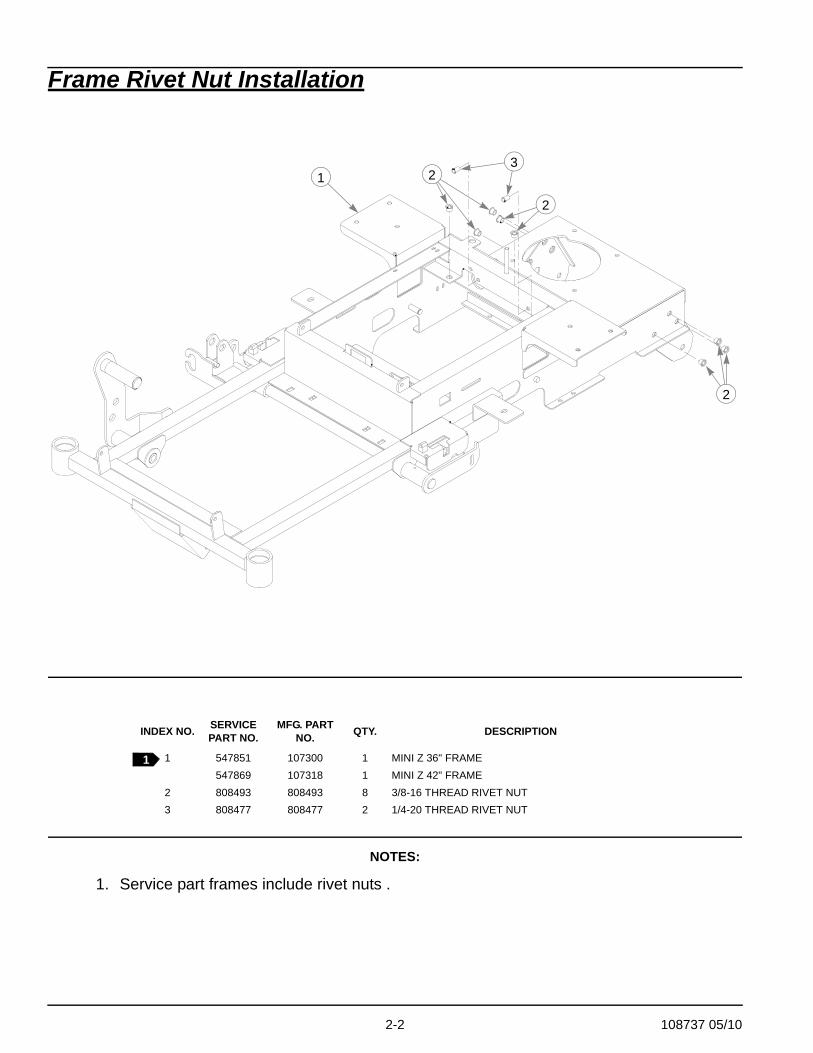
Frame Rivet Nut Installation
NOTES:
1. Service part frames include rivet nuts .
INDEX NO. SERVICE PART NO.
MFG. PART NO. QTY. DESCRIPTION
1 547851 107300 1 MINI Z 36" FRAME547869 107318 1 MINI Z 42" FRAME
2 808493 808493 8 3/8-16 THREAD RIVET NUT3 808477 808477 2 1/4-20 THREAD RIVET NUT
1
2
2
2
3
1
108737 05/10 2-3
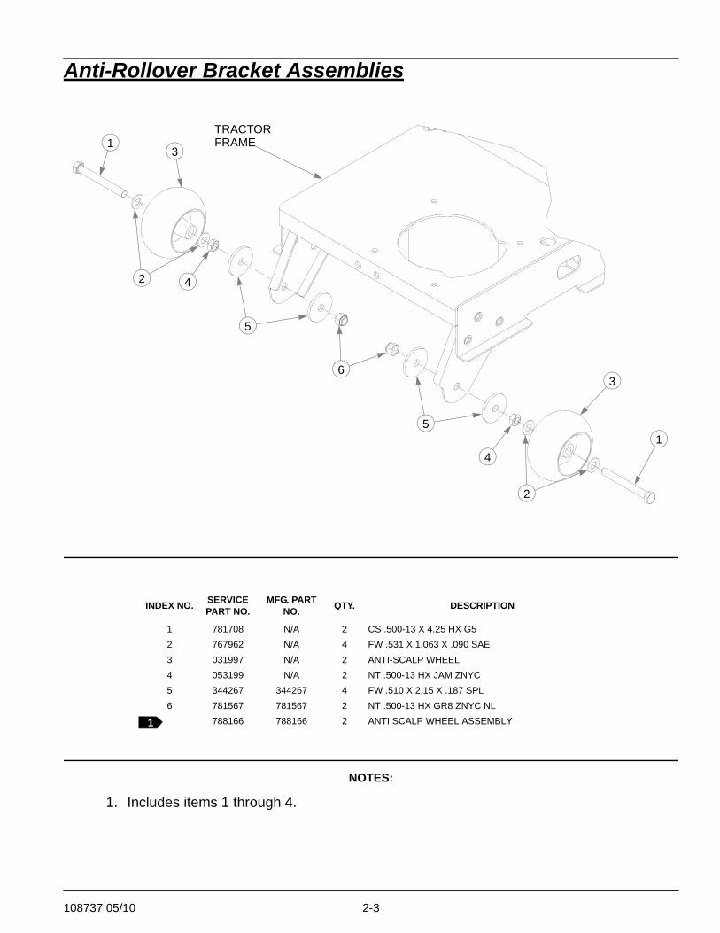
Anti-Rollover Bracket Assemblies
NOTES:
1. Includes items 1 through 4.
INDEX NO. SERVICE PART NO.
MFG. PART NO. QTY. DESCRIPTION
1 781708 N/A 2 CS .500-13 X 4.25 HX G52 767962 N/A 4 FW .531 X 1.063 X .090 SAE3 031997 N/A 2 ANTI-SCALP WHEEL4 053199 N/A 2 NT .500-13 HX JAM ZNYC5 344267 344267 4 FW .510 X 2.15 X .187 SPL6 781567 781567 2 NT .500-13 HX GR8 ZNYC NL
788166 788166 2 ANTI SCALP WHEEL ASSEMBLY
3
1
1
2
2
3
4
4
5
5
TRACTORFRAME
6
1
2-4 108737 05/10
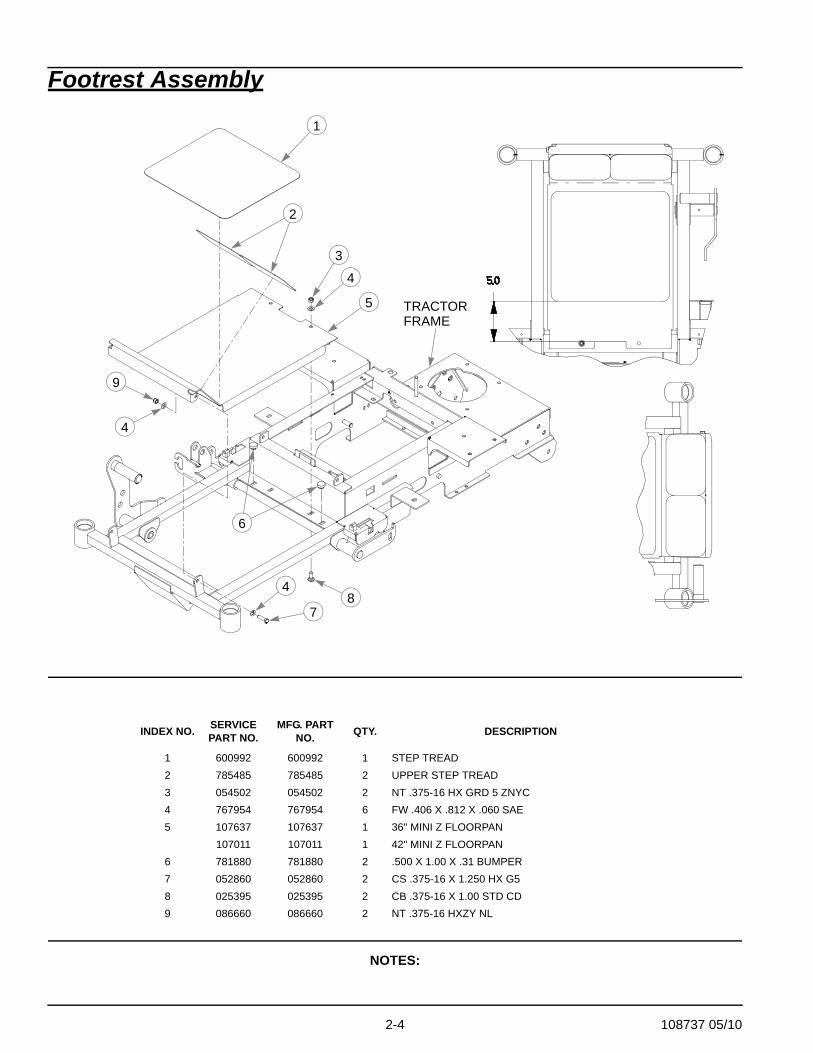
Footrest Assembly
NOTES:
INDEX NO. SERVICE PART NO.
MFG. PART NO. QTY. DESCRIPTION
1 600992 600992 1 STEP TREAD2 785485 785485 2 UPPER STEP TREAD3 054502 054502 2 NT .375-16 HX GRD 5 ZNYC4 767954 767954 6 FW .406 X .812 X .060 SAE5 107637 107637 1 36" MINI Z FLOORPAN
107011 107011 1 42" MINI Z FLOORPAN6 781880 781880 2 .500 X 1.00 X .31 BUMPER7 052860 052860 2 CS .375-16 X 1.250 HX G58 025395 025395 2 CB .375-16 X 1.00 STD CD9 086660 086660 2 NT .375-16 HXZY NL
1
TRACTORFRAME
2
3
4
5
9
4
4
78
6

108737 05/10 3-1
Chapter 3 Contents
Battery Installation . . . . . . . . . . . . . . . . . . . . . . . . . . . . . . . . . . . . . . . 3-2
Deck Lift Assembly . . . . . . . . . . . . . . . . . . . . . . . . . . . . . . . . . . . . . . 3-4
Hydro Transmission Installation. . . . . . . . . . . . . . . . . . . . . . . . . . . . . 3-6
Steering and Brake Assembly . . . . . . . . . . . . . . . . . . . . . . . . . . . . . 3-10
3-2 108737 05/10
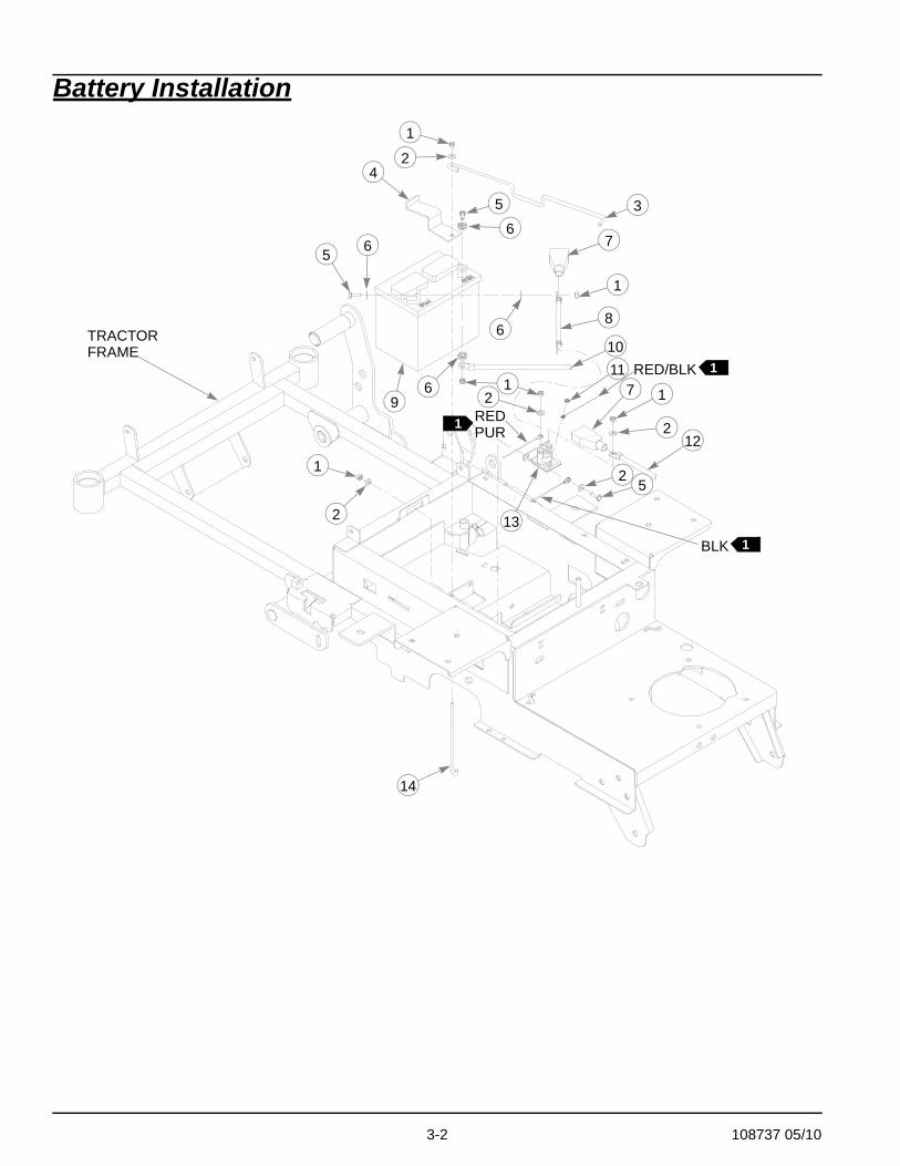
Battery Installation
4
1
5
6
5 6
6
1
7
8
10
14
TRACTORFRAME
96 1
1RED
RED/BLK
PUR1
1
1
BLK 1
2
2
2
2
2
3
5
117
13
12

108737 05/10 3-3
Battery Installation
NOTES:
1. Part of Wire Harness (797829).2. Battery is not installed in export models.
INDEX NO. SERVICE PART NO.
MFG. PART NO. QTY. DESCRIPTION
1 024927 024927 7 NT .250-20 HX GR.5 ZNYC2 768515 768515 7 FW .281 X .625 X .051/.080 HD ZNYC3 601212 601212 1 BATTERY CABLE SUPPORT4 107631 107631 1 MINI Z BATTERY STRAP5 055939 055939 4 CS .250-20 X .750 HX G56 029868 029868 4 LW .250 INT-EXT TOOTH ZNYC7 771428 771428 2 RED BATTERY CABLE BOOT8 792762 792762 1 RED BATTERY CABLE9 740696 740696 1 BATTERY VU1LH-8
10 786640 786640 1 NEGATIVE BATTERY CABLE11 044255 044255 1 NT #10-32 HX ZN12 786632 786632 1 RED BATTERY CABLE13 030817 030817 1 STARTER SOLENOID14 793489 793489 1 BATTERY CLAMP ROD

3-4 108737 05/10
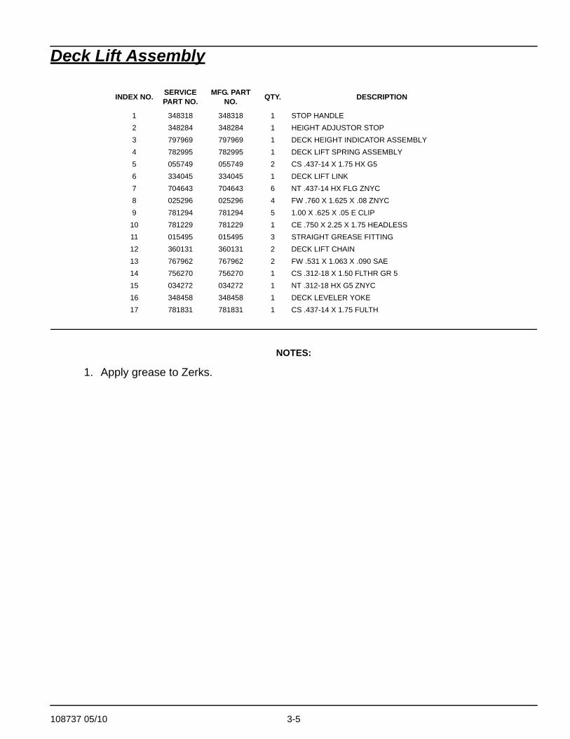
Deck Lift Assembly
1
1
2
3
4
5
8
6
9
8
7
9
810
5
7
9
7
7
7
12
14
15
16
1712
11
11
11
13
8 7
9
1
1
108737 05/10 3-5
Deck Lift Assembly
NOTES:
1. Apply grease to Zerks.
INDEX NO. SERVICE PART NO.
MFG. PART NO. QTY. DESCRIPTION
1 348318 348318 1 STOP HANDLE2 348284 348284 1 HEIGHT ADJUSTOR STOP3 797969 797969 1 DECK HEIGHT INDICATOR ASSEMBLY4 782995 782995 1 DECK LIFT SPRING ASSEMBLY5 055749 055749 2 CS .437-14 X 1.75 HX G56 334045 334045 1 DECK LIFT LINK7 704643 704643 6 NT .437-14 HX FLG ZNYC8 025296 025296 4 FW .760 X 1.625 X .08 ZNYC9 781294 781294 5 1.00 X .625 X .05 E CLIP
10 781229 781229 1 CE .750 X 2.25 X 1.75 HEADLESS11 015495 015495 3 STRAIGHT GREASE FITTING12 360131 360131 2 DECK LIFT CHAIN13 767962 767962 2 FW .531 X 1.063 X .090 SAE14 756270 756270 1 CS .312-18 X 1.50 FLTHR GR 515 034272 034272 1 NT .312-18 HX G5 ZNYC16 348458 348458 1 DECK LEVELER YOKE17 781831 781831 1 CS .437-14 X 1.75 FULTH
3-6 108737 05/10
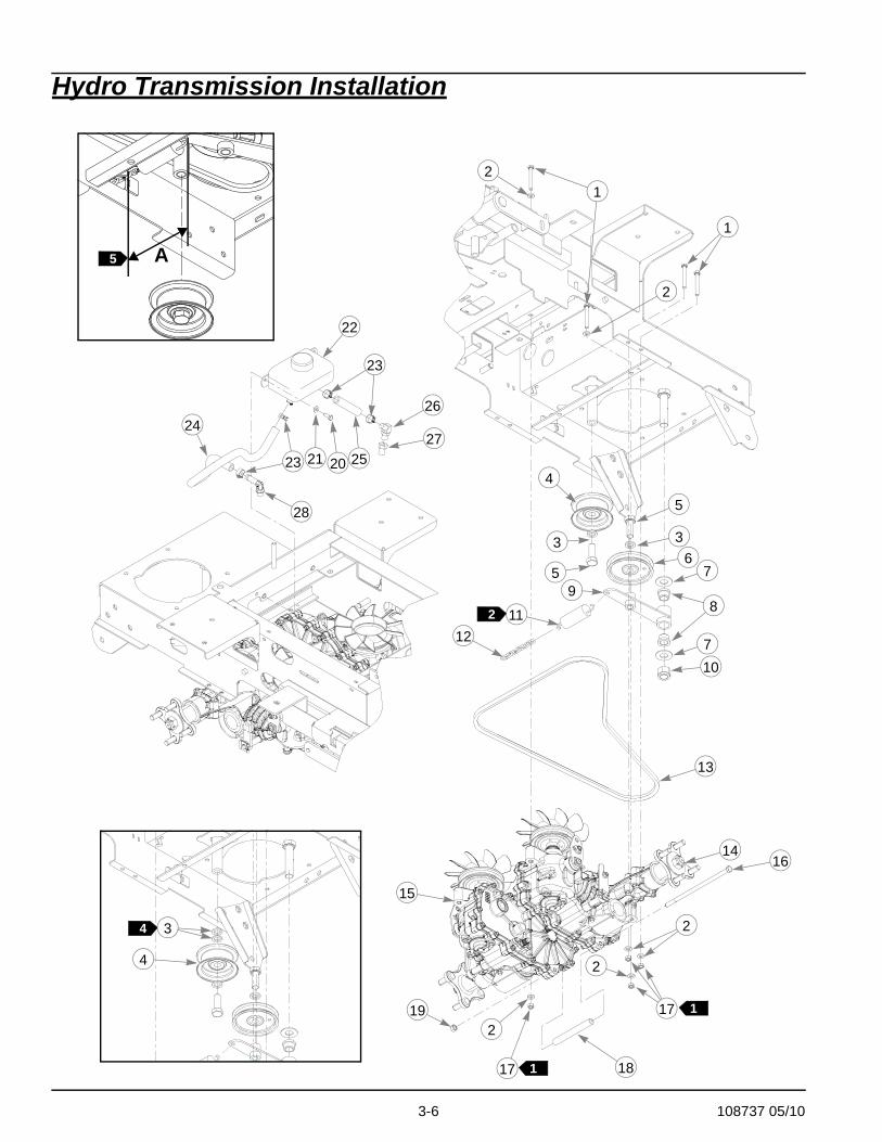
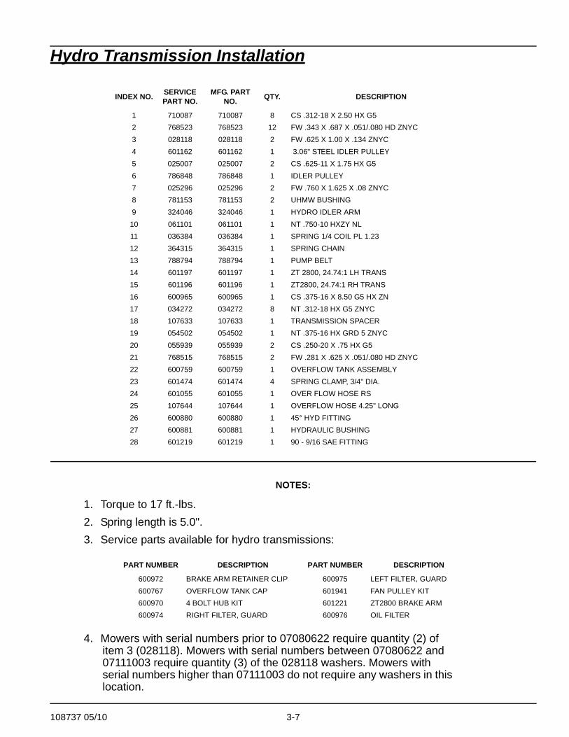
Hydro Transmission Installation
3
4
1
1
3 3
4
5
5
67
7
89
1112
10
13
14
15
16
2
2
217
17 18
19
21 20
22
23
23
24
25
28
26
27
1
12
2
2
5 A
4
108737 05/10 3-7
Hydro Transmission Installation
NOTES:
1. Torque to 17 ft.-lbs.2. Spring length is 5.0".3. Service parts available for hydro transmissions:
4. Mowers with serial numbers prior to 07080622 require quantity (2) of item 3 (028118). Mowers with serial numbers between 07080622 and 07111003 require quantity (3) of the 028118 washers. Mowers with serial numbers higher than 07111003 do not require any washers in this location.
INDEX NO. SERVICE PART NO.
MFG. PART NO. QTY. DESCRIPTION
1 710087 710087 8 CS .312-18 X 2.50 HX G52 768523 768523 12 FW .343 X .687 X .051/.080 HD ZNYC3 028118 028118 2 FW .625 X 1.00 X .134 ZNYC4 601162 601162 1 3.06" STEEL IDLER PULLEY5 025007 025007 2 CS .625-11 X 1.75 HX G56 786848 786848 1 IDLER PULLEY7 025296 025296 2 FW .760 X 1.625 X .08 ZNYC8 781153 781153 2 UHMW BUSHING9 324046 324046 1 HYDRO IDLER ARM
10 061101 061101 1 NT .750-10 HXZY NL11 036384 036384 1 SPRING 1/4 COIL PL 1.2312 364315 364315 1 SPRING CHAIN13 788794 788794 1 PUMP BELT14 601197 601197 1 ZT 2800, 24.74:1 LH TRANS15 601196 601196 1 ZT2800, 24.74:1 RH TRANS16 600965 600965 1 CS .375-16 X 8.50 G5 HX ZN17 034272 034272 8 NT .312-18 HX G5 ZNYC18 107633 107633 1 TRANSMISSION SPACER19 054502 054502 1 NT .375-16 HX GRD 5 ZNYC20 055939 055939 2 CS .250-20 X .75 HX G521 768515 768515 2 FW .281 X .625 X .051/.080 HD ZNYC22 600759 600759 1 OVERFLOW TANK ASSEMBLY23 601474 601474 4 SPRING CLAMP, 3/4" DIA.24 601055 601055 1 OVER FLOW HOSE RS25 107644 107644 1 OVERFLOW HOSE 4.25" LONG26 600880 600880 1 45° HYD FITTING27 600881 600881 1 HYDRAULIC BUSHING28 601219 601219 1 90 - 9/16 SAE FITTING
PART NUMBER DESCRIPTION PART NUMBER DESCRIPTION
600972 BRAKE ARM RETAINER CLIP 600975 LEFT FILTER, GUARD600767 OVERFLOW TANK CAP 601941 FAN PULLEY KIT600970 4 BOLT HUB KIT 601221 ZT2800 BRAKE ARM600974 RIGHT FILTER, GUARD 600976 OIL FILTER

3-8 108737 05/10
5. Spring length after tensioning should be 4.5”-5.5” (dimension A), measured from outside of hook to outside of hook.

108737 05/10 3-9
This page intentionally left blank.
3-10 108737 05/10
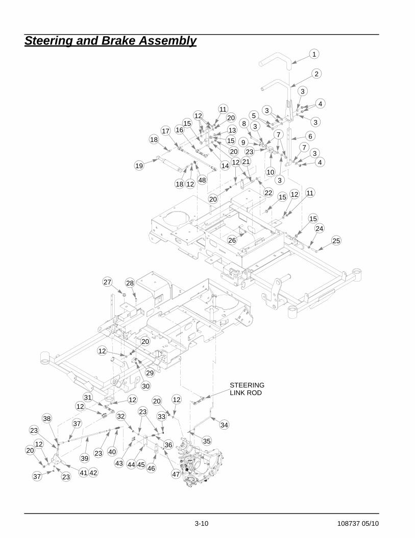
Steering and Brake Assembly1
2
3
3
4
5
6
8
3
7
73
4
923
10
11
1112
12
1212
12
14
15
15
20
20
20
1718
18
19
16
15
15
26
21
27
29
20
31
37
23
38
37
3944
32
4746
40
STEERINGLINK ROD
13
20
25
24
20
35
23
3
12
{
4341
3433
36
23
28
30
12
23
4542
22
348
12
12

108737 05/10 3-11
Steering and Brake Assembly
INDEX NO. SERVICE PART NO.
MFG. PART NO. QTY. DESCRIPTION
1 781260 N/A 2 STEERING BAR GRIP2 360487 360487 2 STEERING BAR3 767954 767954 14 FW .406 X .812 X .060 SAE4 086660 086660 6 NT .375-16 HX ZNYC NL5 705178 705178 4 CS .375-16 X 1.75 HX G56 797753 797753 2 STEERING ARM7 797779 797779 8 IGUS BUSHING8 005108 005108 2 CS .375-16 X 3.50 HX G5 ZNYC9 079186 079186 2 CS .312-18 X 1.25 HX G5
10 600896 600896 1 LH STEERING BLOCK600895 600895 1 RH STEERING BLOCK
11 034272 034272 4 NT .312-18 HX G5 ZNYC12 768523 768523 30 FW .343 X .687 X .051/.080 HD ZNYC13 718288 718288 2 FW .516 X .875 X .09 ZNYC14 325464 325464 2 STEERING CONTROL ARM15 768259 768259 8 IGUS BUSHING16 794396 794396 2 STEERING LINK ROD ASSEMBLY17 793646 793646 2 PUMP ROD ADJUSTER ASSEMBLY18 781922 781922 4 DAMPER BALL STUD19 600221 600221 2 STEERING DAMPER20 023655 023655 12 NT .312-24 HXZY NL21 793612 793612 2 STEERING DRIVE ARM22 704775 704775 2 FW .531 X .812 X .060 ZNYC23 768515 768515 12 FW .281 X .625 X .051/.080 HD24 054502 054502 2 NT .375-16 HX GRD 5 ZNYC25 600878 600878 2 CS .375-16 X 1.75 G5 FULTD26 793059 793059 2 E CLIP (1/2") .80 X .396 X .04227 781567 781567 2 NT .500-13 HX G8 ZNYC NL28 063198 063198 4 CS 10-24 X .750 HXFLK ZN29 781211 781211 2 PUSH BUTTON SWITCH30 059832 059832 4 NT #10-24 HX NL ZN31 781583 781583 2 BRAKE ROD ASSEMBLY32 024927 024927 2 NT .250-20 HX GR.5 ZNYC33 068551 068551 2 NT .250-20 HXZY NL34 601088 601088 2 TOWLINK ROD35 048553 048553 2 CP .062D X 1.00 LG HML ZNYC36 601211 601211 2 BRAKE OVERTRAVEL SPRING37 058842 058842 4 NT .250-28 HX JAM ZNYC38 601201 601201 2 BALL JOINT, WITH STUD, 1/4-2839 601200 601200 2 BRAKE ACTUATOR ROD40 061572 061572 2 COMPRESS SPRING ZN PLD41 108468 108468 1 LEFT BRAKE ARM42 108467 108467 1 RIGHT BRAKE ARM43 600972 N/A 2 BRAKE ARM RETAINER CLIP44 108598 108598 1 LEFT BRAKE ACTUATOR BRACKET45 108588 108588 1 RIGHT BRAKE ACTUATOR BRACKET46 601221 N/A 2 ZT2800 BRAKE ARM47 055939 055939 2 CS .250-20 X .750 HX G548 029876 029876 2 LW .312 INT-EXT TOOTH Z
1

3-12 108737 05/10
NOTES:
1. Included with Item 2 (360487 Steering Bar).

108737 05/10 4-1
Chapter 4 Contents
Kawasaki Engine Installation . . . . . . . . . . . . . . . . . . . . . . . . . . . . . . . 4-2
Fuel System Installation. . . . . . . . . . . . . . . . . . . . . . . . . . . . . . . . . . . 4-6
Instrument Panel Installation . . . . . . . . . . . . . . . . . . . . . . . . . . . . . . . 4-8
Kawasaki Electrical Schematic (601218). . . . . . . . . . . . . . . . . . . . . 4-10
4-2 108737 05/10
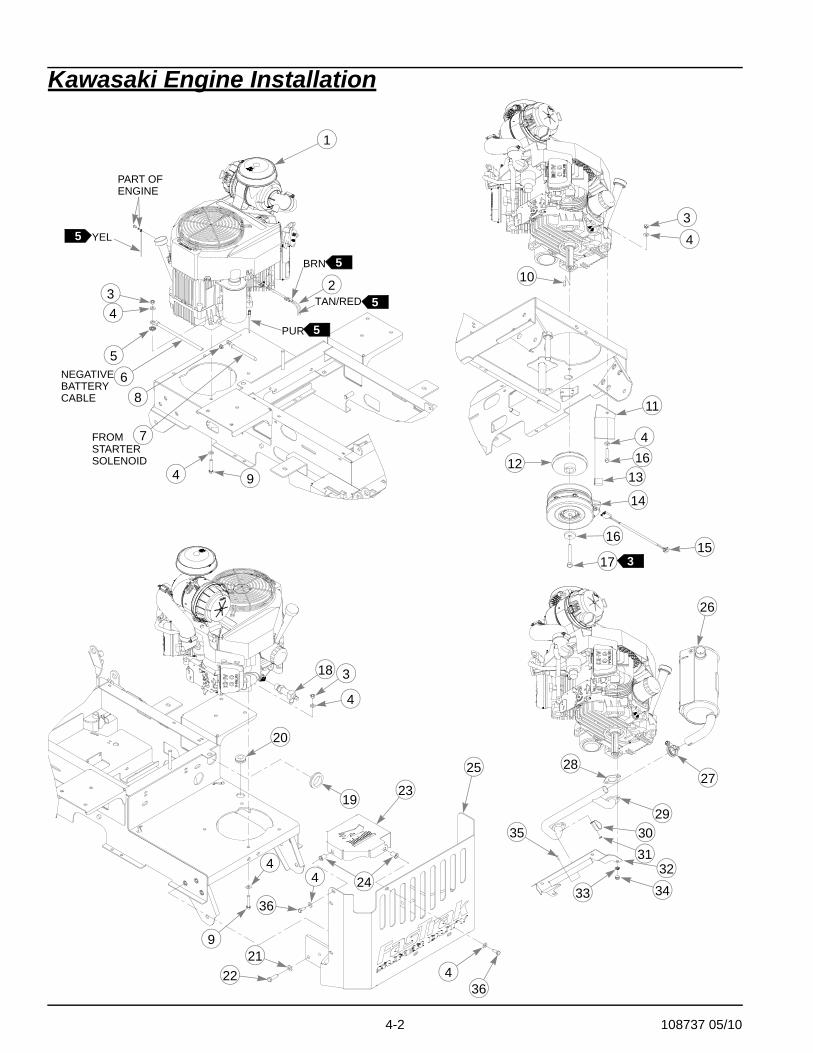
Kawasaki Engine Installation
5
1
34
4
5
9
2
34
4
4
16
3
9
4
10
11
1213
14
16
17
18
2122
25
26
2728
293031
32
33 34
35
153
TAN/RED
PUR
BRN
5
5
NEGATIVEBATTERYCABLE 8
5
PART OFENGINE
YEL
FROMSTARTERSOLENOID
6
7
19
20
23
244
36
364

108737 05/10 4-3
Kawasaki Engine Installation
NOTES:
1. Used on 928192 only.2. Used on 928200 only.3. Torque bolt to 48-45 ft-lbs. Replace (do not reuse) capscrew if removed
or loosened. Use only hand tools to install this fastener.4. Engine speed; 3550±50 rpm.
INDEX NO. SERVICE PART NO.
MFG. PART NO. QTY. DESCRIPTION
1 N/A 797803 1 17 HP KAI KAWASAKI ENGINEN/A 797811 19 HP KAI KAWASAKI ENGINE
2 601218 601218 1 WIRE HARNESS, MNZ KAW3 034272 034272 4 NT .312-18 HX G5 ZNYC4 768523 768523 10 FW .343 X .687 X .051/.080 HD ZNYC5 029876 029876 1 LW .312 INT-EXT TOOTH ZNYC6 786640 N/A 1 BATTERY CABLE7 786632 N/A 1 RED BATTERY CABLE8 016816 016816 1 NT .250-20 HX FL LK ZNYC9 050161 050161 4 CS .312-18 X 1.75 HX G5
10 712372 712372 1 KEY 1/4 SQ X 0.66 LONG11 330274 330274 1 WARNER CLUTCH ANCHOR12 799429 799429 1 4.5" O.D. “A” SEC PULLEY13 784918 784918 1 RUBBER BUMPER14 601325 601325 1 FASTRAK CLUTCH
784835 N/A 1 FASTRAK CLUTCH15 791251 N/A 1 CLUTCH PIGTAIL HARNESS16 763417 763417 1 FW .454X1.50X.25017 785048 785048 1 CS .437-20 X 3.00 HX G5 ZNYC18 796524 796524 1 M 20 X 2.5 OIL DRAIN VALVE19 794644 794644 1 GM 1.50 X 2.12 X 1.75 X .1220 748681 748681 1 GM .75 X 1.35 X 1.06 X .18-GR21 767954 767954 6 FW .406 X .812 X .060 SAE22 052860 052860 6 CS .375-16 X 1.25 HX G523 108071 108071 1 MUFFLER COVER24 808485 N/A 2 RIVET NUT, 5/16-18 THREADE25 107608 107608 1 ENGINE GUARD26 600904 N/A 1 MUFFLER 17/19 KAI27 600907 N/A 1 MUFFLER CLAMP 17/19 KAI28 791558 N/A 2 EXHAUST GASKET29 600902 N/A 1 MANIFOLD 17/19 KAI30 600906 N/A 1 MANIFOLD CLMP 17/19 KAI31 005355 N/A 1 NT M4-.70-5 HX ZNYC32 600903 N/A 1 HEAT SHIELD 17/19 KAI33 017004 N/A 4 LW .312 MED SPRING ZNYC34 782664 N/A 4 NT M8-1.25 HX STAINLESS35 008979 N/A 1 MS M 4-.70 X 12 PH CR ZN36 034280 034280 2 CS .312-18X .750 HX G5
12
7

4-4 108737 05/10
5. Part of item 2 (601218 Wire Harness).6. Engine oil capacity: Check engine owners manual.7. Use for mowers with serial numbers prior to 07080622.

108737 05/10 4-5
This page intentionally left blank.
4-6 108737 05/10
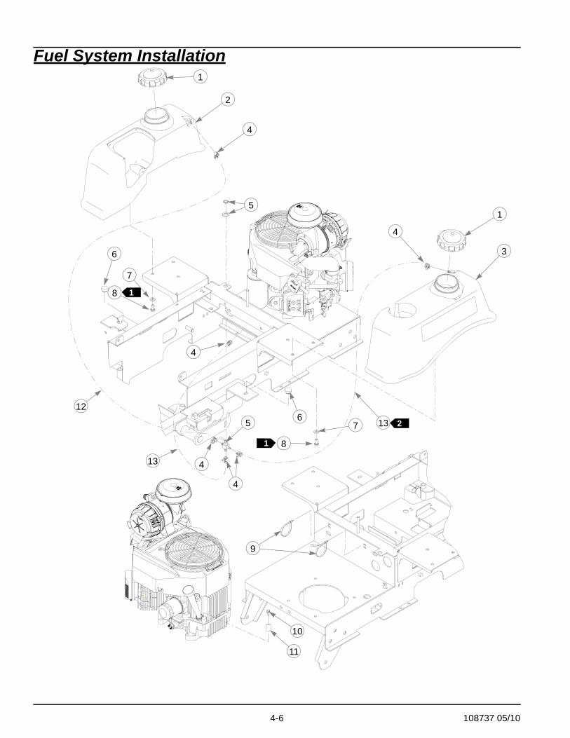
Fuel System Installation1
1
1
2
3
4
4
4
4
5
5
6
6
7
8
8
7
10
11
1
12
13
13
4
9
2

108737 05/10 4-7
Fuel System Installation
NOTES:
1. Torque to 20 ft-lbs.2. For mowers with serial numbers prior to 07041752 use 21" long fuel line
for the left side tank; and 8.5" long fuel line for the line between the valve and the engine; and 25.5" long fuel line for the right side tank.
INDEX NO. SERVICE PART NO.
MFG. PART NO. QTY. DESCRIPTION
1 779306 779306 2 3.5" FUEL CAP2 792960 792960 1 FUEL TANK RIGHT SIDE 36-423 792978 792978 1 FUEL TANK LEFT SIDE 36-424 000323 000323 6 CLIP5 745059 745059 1 3-WAY FUEL VALVE6 781880 781880 2 BUMPER, .500 X 1.00 X .312 X .1887 767954 767954 6 FW .406 X .812 X .060 SAE HD ZN8 055822 055822 6 CS .375-16 X HX GRD 5 ZNYC9 000331 000331 2 SMALL, SHORT WIRE TIE
10 792796 792796 1 SC M 6-1.0X15 HX FL STP11 043570 043570 1 SINGLE HOSE CLIP12 015818 015818 1 FUEL LINE 21.5" LONG13 015818 015818 2 FUEL LINE 9" LONG
1
22
4-8 108737 05/10
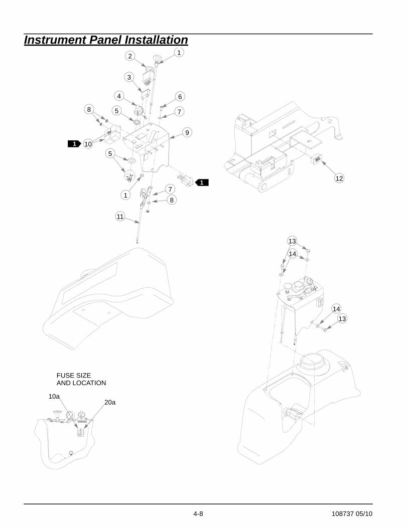
Instrument Panel Installation1
1
2
3
4
5
6
7
9
8
10
178
11
13
14
1413
1
20a10a
FUSE SIZEAND LOCATION
12
5

108737 05/10 4-9
Instrument Panel Installation
NOTES:
1. Part of 601218 (Wire Harness).
INDEX NO. SERVICE PART NO.
MFG. PART NO. QTY. DESCRIPTION
1 785030 785030 1 CHOKE CABLE2 776476 776476 1 PTO SWITCH3 712257 712257 1 RED INDICATOR LIGHT4 785808 785808 1 INDAK COATED KEY5 045898 045898 1 KEY SWITCH6 714998 714998 2 MS #10-24 X .625 HX ZN7 704932 704932 4 FW .219 X .500 X .048 ZNYC8 059832 059832 4 NT #10-24 HX NL ZN9 321059 321059 1 INSTRUMENT PANEL
10 026237 N/A 2 RELAY11 601096 601096 1 THROTTLE CABLE12 769166 769166 1 HOUR METER13 055947 055947 3 CS .250-20 X .50 HX G5 ZNYC14 768515 768515 3 FW .281 X .625 X .051/.080 HD ZNYC

4-10 108737 05/10
Kawasaki Electrical Schematic (601218)

108737 05/10 5-1
Chapter 5 Contents
Front Wheel Assembly. . . . . . . . . . . . . . . . . . . . . . . . . . . . . . . . . . . . 5-2
Front Wheel Breakdown—786061. . . . . . . . . . . . . . . . . . . . . . . . . . . 5-3
Drive Wheel Assembly. . . . . . . . . . . . . . . . . . . . . . . . . . . . . . . . . . . . 5-4
5-2 108737 05/10
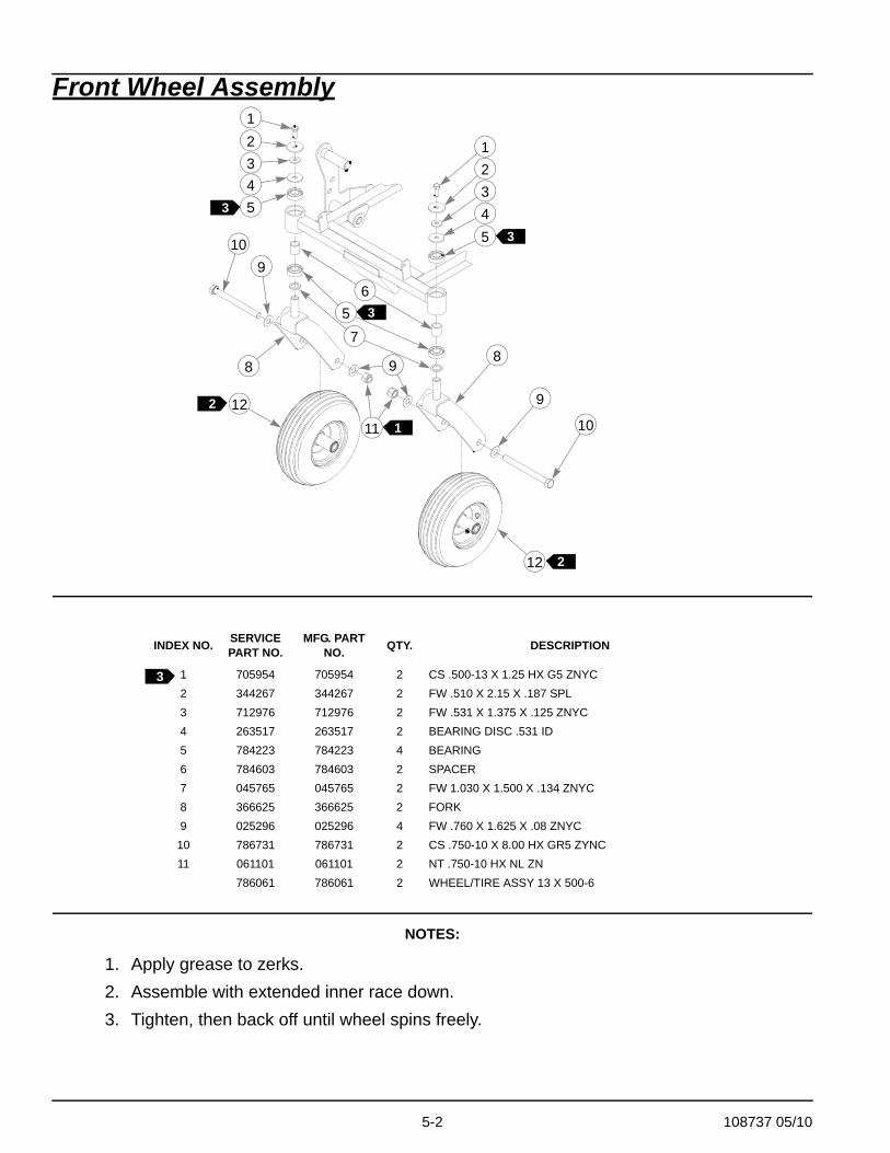
Front Wheel Assembly
NOTES:
1. Apply grease to zerks.2. Assemble with extended inner race down.3. Tighten, then back off until wheel spins freely.
INDEX NO. SERVICE PART NO.
MFG. PART NO. QTY. DESCRIPTION
1 705954 705954 2 CS .500-13 X 1.25 HX G5 ZNYC2 344267 344267 2 FW .510 X 2.15 X .187 SPL3 712976 712976 2 FW .531 X 1.375 X .125 ZNYC4 263517 263517 2 BEARING DISC .531 ID5 784223 784223 4 BEARING6 784603 784603 2 SPACER7 045765 045765 2 FW 1.030 X 1.500 X .134 ZNYC8 366625 366625 2 FORK9 025296 025296 4 FW .760 X 1.625 X .08 ZNYC
10 786731 786731 2 CS .750-10 X 8.00 HX GR5 ZYNC11 061101 061101 2 NT .750-10 HX NL ZN
786061 786061 2 WHEEL/TIRE ASSY 13 X 500-6
123
5
8
10
9
12
12
123
5
65
7
11
9
109
8
3
1
2
2
3
3 4
4
3
108737 05/10 5-3
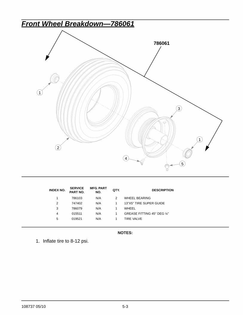
Front Wheel Breakdown—786061
NOTES:
1. Inflate tire to 8-12 psi.
INDEX NO. SERVICE PART NO.
MFG. PART NO. QTY. DESCRIPTION
1 786103 N/A 2 WHEEL BEARING2 747402 N/A 1 13"X5" TIRE SUPER GUIDE3 786079 N/A 1 WHEEL4 015511 N/A 1 GREASE FITTING 45° DEG ¼"5 019521 N/A 1 TIRE VALVE
1
786061
3
1
2
45
5-4 108737 05/10
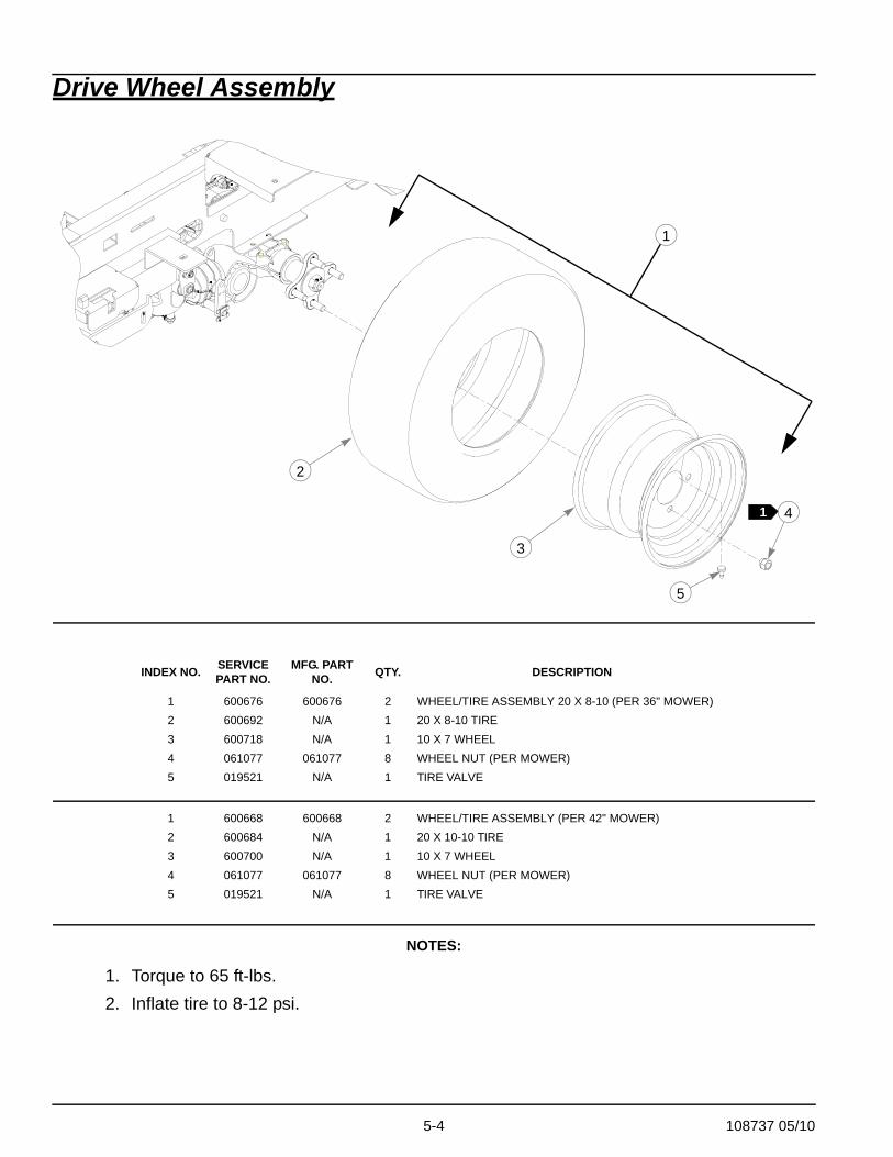
Drive Wheel Assembly
NOTES:
1. Torque to 65 ft-lbs.2. Inflate tire to 8-12 psi.
INDEX NO. SERVICE PART NO.
MFG. PART NO. QTY. DESCRIPTION
1 600676 600676 2 WHEEL/TIRE ASSEMBLY 20 X 8-10 (PER 36" MOWER)2 600692 N/A 1 20 X 8-10 TIRE3 600718 N/A 1 10 X 7 WHEEL4 061077 061077 8 WHEEL NUT (PER MOWER)5 019521 N/A 1 TIRE VALVE
1 600668 600668 2 WHEEL/TIRE ASSEMBLY (PER 42" MOWER)2 600684 N/A 1 20 X 10-10 TIRE3 600700 N/A 1 10 X 7 WHEEL4 061077 061077 8 WHEEL NUT (PER MOWER)5 019521 N/A 1 TIRE VALVE
4
5
1
2
3
1

108737 05/10 6-1
Chapter 6 Contents
Deck Assembly 36" SN Prior to 10020000 . . . . . . . . . . . . . . . . . . . . 6-2
Deck Assembly 36" SN Higher Than 10020000 . . . . . . . . . . . . . . . . 6-4
Deck Pulley Assembly 36". . . . . . . . . . . . . . . . . . . . . . . . . . . . . . . . . 6-6
Deck Assembly 42" SN Prior to 10020000 . . . . . . . . . . . . . . . . . . . . 6-8
Deck Assembly 42" SN Higher Than 10020000 . . . . . . . . . . . . . . . 6-10
Deck Pulley Assembly 42". . . . . . . . . . . . . . . . . . . . . . . . . . . . . . . . 6-12
Spindle Assembly—783506. . . . . . . . . . . . . . . . . . . . . . . . . . . . . . . 6-14
6-2 108737 05/10
Deck Assembly 36" SN Prior to 10020000
1
3
4
5
6
3
78
8
9
9
8
10
10
11
8
11
1213 14
16
15
12
15
14
16
13
18
2
17 17
108737 05/10 6-3
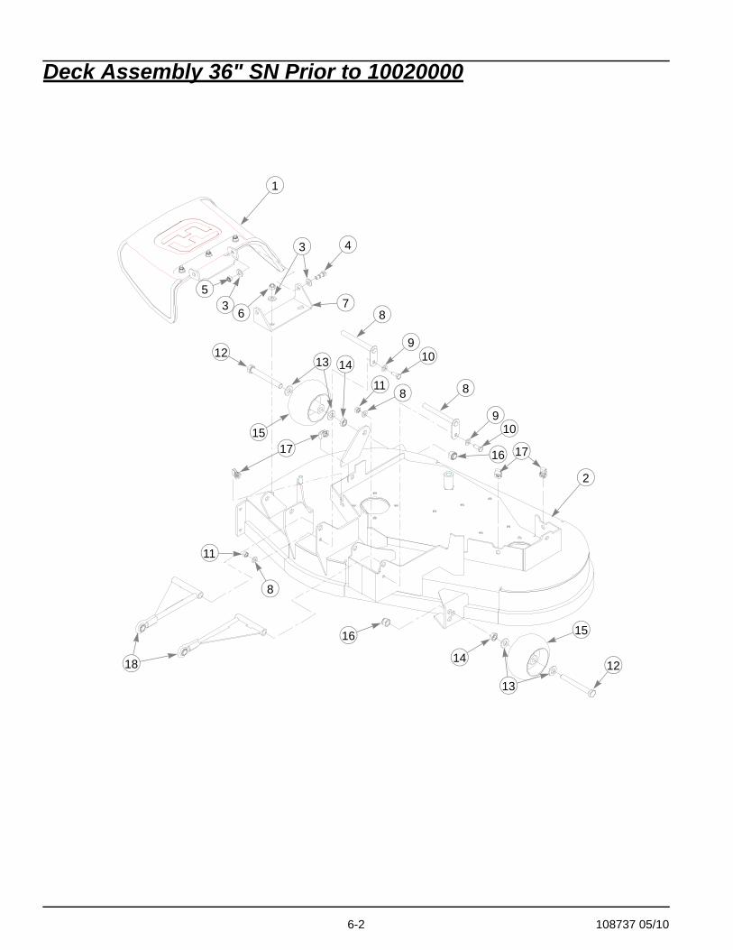
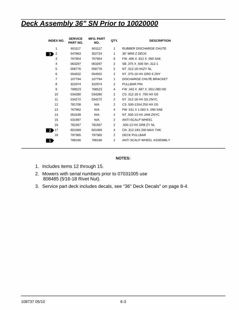
Deck Assembly 36" SN Prior to 10020000
NOTES:
1. Includes items 12 through 15.2. Mowers with serial numbers prior to 07031005 use
808485 (5⁄16-18 Rivet Nut).3. Service part deck includes decals, see “36" Deck Decals” on page 8-4.
INDEX NO. SERVICE PART NO.
MFG. PART NO. QTY. DESCRIPTION
1 601117 601117 1 RUBBER DISCHARGE CHUTE2 547863 352724 1 36" MINI Z DECK3 767954 767954 6 FW .406 X .812 X .060 SAE4 063297 063297 2 SB .375 X .500 SH .312-15 058776 058776 2 NT .312-18 HXZY NL6 054502 054502 2 NT .375-16 HX GRD 5 ZNY7 107794 107794 1 DISCHARGE CHUTE BRACKET8 322974 322974 2 PULLBAR PIN9 768523 768523 4 FW .343 X .687 X .051/.080 HD
10 034280 034280 2 CS .312-18 X .750 HX G511 034272 034272 2 NT .312-18 HX G5 ZNYC12 781708 N/A 2 CS .500-13X4.250 HX G513 767962 N/A 4 FW .531 X 1.063 X .090 SAE14 053199 N/A 2 NT .500-13 HX JAM ZNYC15 031997 N/A 2 ANTI-SCALP WHEEL16 781567 781567 2 .500-13 HX GR8 ZY NL17 601069 601069 4 CN .312-18X.200 MAX THK18 797365 797365 2 DECK PULLBAR
788166 788166 2 ANTI SCALP WHEEL ASSEMBLY
3
2
1
6-4 108737 05/10
Deck Assembly 36" SN Higher Than 10020000
19
17
171618
11
78
7
8
9
9
10
128
1413
1
23
5
3
4
6
2
15
128
11
108737 05/10 6-5
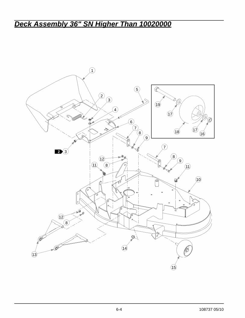
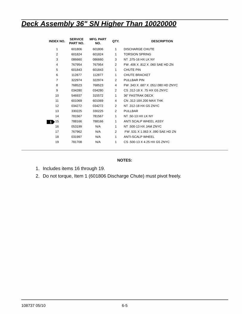
Deck Assembly 36" SN Higher Than 10020000
NOTES:
1. Includes items 16 through 19.2. Do not torque, Item 1 (601806 Discharge Chute) must pivot freely.
INDEX NO. SERVICE PART NO.
MFG. PART NO. QTY. DESCRIPTION
1 601806 601806 1 DISCHARGE CHUTE2 601824 601824 1 TORSION SPRING3 086660 086660 3 NT .375-16 HX LK NY4 767954 767954 2 FW .406 X .812 X .060 SAE HD ZN5 601843 601843 1 CHUTE PIN6 112877 112877 1 CHUTE BRACKET7 322974 322974 2 PULLBAR PIN8 768523 768523 4 FW .343 X .687 X .051/.080 HD ZNYC9 034280 034280 2 CS .312-18 X .75 HX G5 ZNYC
10 546937 315572 1 36" FASTRAK DECK11 601069 601069 4 CN .312-18X.200 MAX THK12 034272 034272 2 NT .312-18 HX G5 ZNYC13 330225 330225 2 PULLBAR14 781567 781567 1 NT .50-13 HX LK NY15 788166 788166 1 ANTI SCALP WHEEL ASSY16 053199 N/A 1 NT .500-13 HX JAM ZNYC17 767962 N/A 2 FW .531 X 1.063 X .090 SAE HD ZN18 031997 N/A 1 ANTI-SCALP WHEEL19 781708 N/A 1 CS .500-13 X 4.25 HX G5 ZNYC
1
6-6 108737 05/10
Deck Pulley Assembly 36"
1
2
4
5
6
7
89 10
11
12
13
13
14
15
1416
17
1718
18
4
6
719
19
19
20
20
20
20
2218
18
21
21
23
23
24
25
14
13
BELT GUIDEINDEXING
DECKASSEMBLY
1
1
1
1 13
5
14
19
3
108737 05/10 6-7
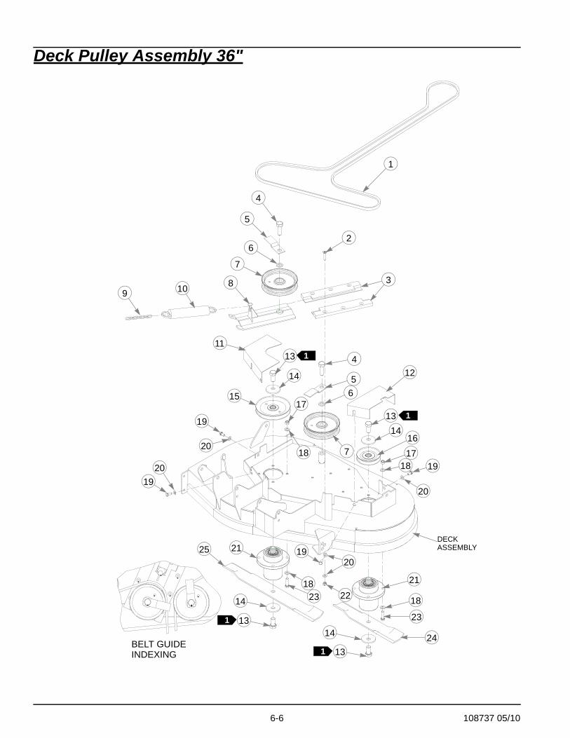
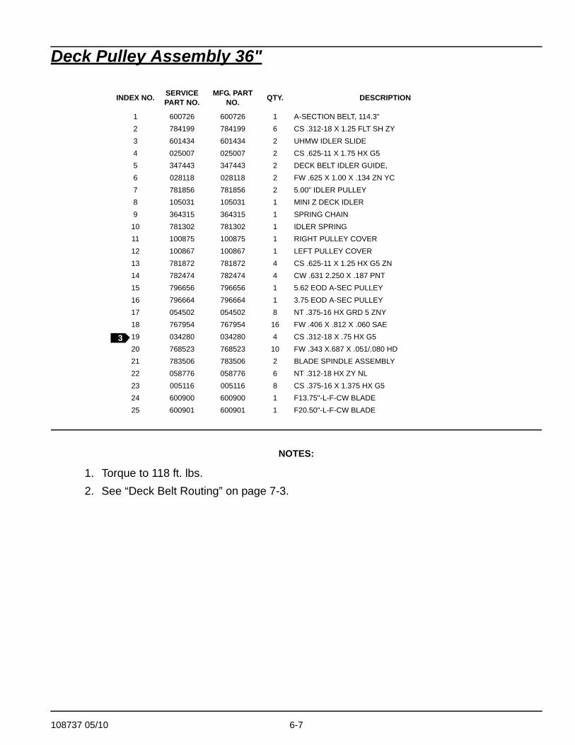
Deck Pulley Assembly 36"
NOTES:
1. Torque to 118 ft. lbs.2. See “Deck Belt Routing” on page 7-3.
INDEX NO. SERVICE PART NO.
MFG. PART NO. QTY. DESCRIPTION
1 600726 600726 1 A-SECTION BELT, 114.3"2 784199 784199 6 CS .312-18 X 1.25 FLT SH ZY3 601434 601434 2 UHMW IDLER SLIDE4 025007 025007 2 CS .625-11 X 1.75 HX G55 347443 347443 2 DECK BELT IDLER GUIDE,6 028118 028118 2 FW .625 X 1.00 X .134 ZN YC7 781856 781856 2 5.00" IDLER PULLEY8 105031 105031 1 MINI Z DECK IDLER9 364315 364315 1 SPRING CHAIN
10 781302 781302 1 IDLER SPRING11 100875 100875 1 RIGHT PULLEY COVER12 100867 100867 1 LEFT PULLEY COVER13 781872 781872 4 CS .625-11 X 1.25 HX G5 ZN14 782474 782474 4 CW .631 2.250 X .187 PNT15 796656 796656 1 5.62 EOD A-SEC PULLEY16 796664 796664 1 3.75 EOD A-SEC PULLEY17 054502 054502 8 NT .375-16 HX GRD 5 ZNY18 767954 767954 16 FW .406 X .812 X .060 SAE19 034280 034280 4 CS .312-18 X .75 HX G520 768523 768523 10 FW .343 X.687 X .051/.080 HD21 783506 783506 2 BLADE SPINDLE ASSEMBLY22 058776 058776 6 NT .312-18 HX ZY NL23 005116 005116 8 CS .375-16 X 1.375 HX G524 600900 600900 1 F13.75"-L-F-CW BLADE25 600901 600901 1 F20.50"-L-F-CW BLADE
3
6-8 108737 05/10
Deck Assembly 42" SN Prior to 10020000
1
2
3
3 4
5
67
8
8
910
910
9
9
11
11
12
13 14 15
12
1314
15
16 1616
18
17
17
16
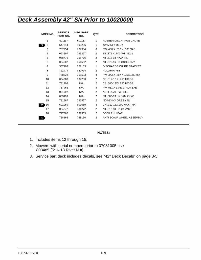
108737 05/10 6-9
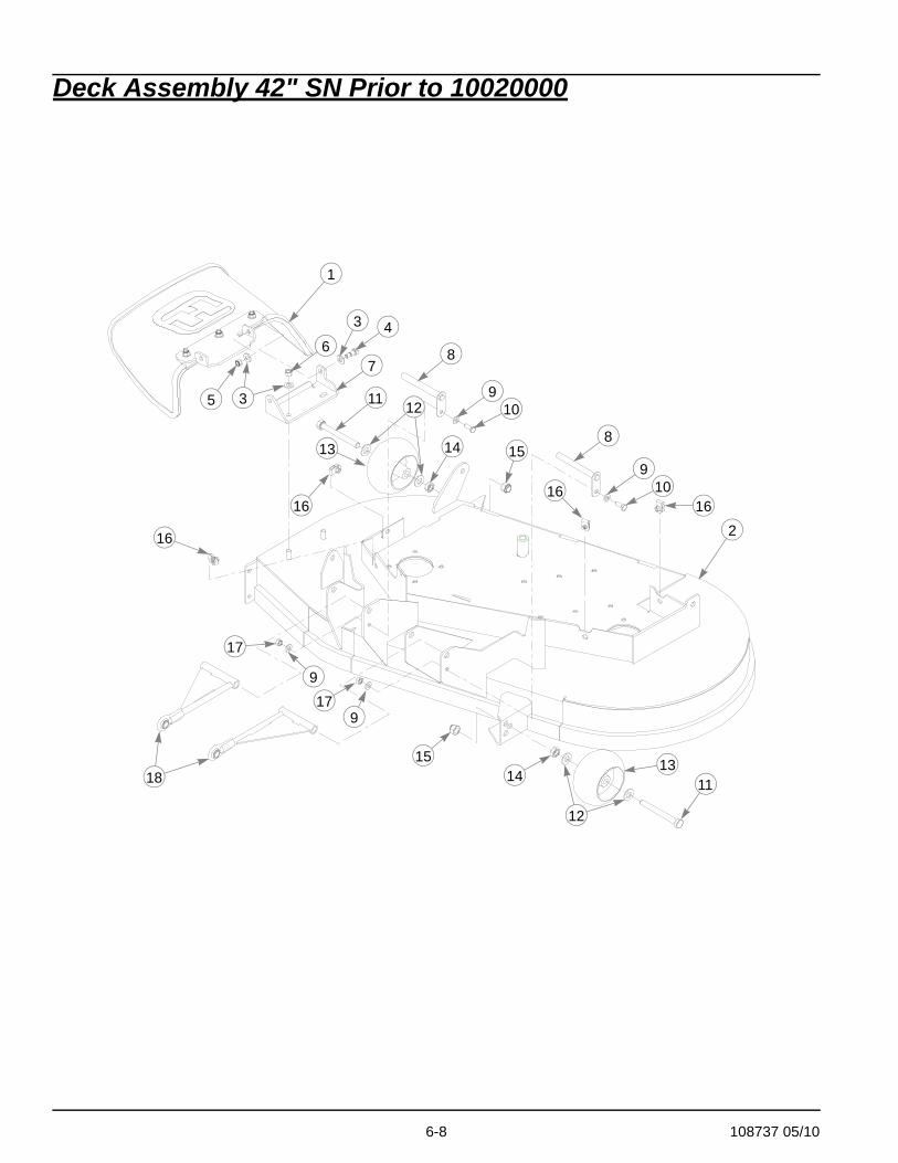
Deck Assembly 42" SN Prior to 10020000
NOTES:
1. Includes items 12 through 15.2. Mowers with serial numbers prior to 07031005 use
808485 (5⁄16-18 Rivet Nut).3. Service part deck includes decals, see “42" Deck Decals” on page 8-5.
INDEX NO. SERVICE PART NO.
MFG. PART NO. QTY. DESCRIPTION
1 601117 601117 1 RUBBER DISCHARGE CHUTE2 547844 105296 1 42" MINI Z DECK3 767954 767954 6 FW .406 X .812 X .060 SAE4 063297 063297 2 SB .375 X .500 SH .312-15 058776 058776 2 NT .312-18 HXZY NL6 054502 054502 2 NT .375-16 HX GRD 5 ZNY7 357103 357103 1 DISCHARGE CHUTE BRACKET8 322974 322974 2 PULLBAR PIN9 768523 768523 4 FW .343 X .687 X .051/.080 HD
10 034280 034280 2 CS .312-18 X .750 HX G511 781708 N/A 2 CS .500-13X4.250 HX G512 767962 N/A 4 FW .531 X 1.063 X .090 SAE13 031997 N/A 2 ANTI-SCALP WHEEL14 053199 N/A 2 NT .500-13 HX JAM ZNYC15 781567 781567 2 .500-13 HX GR8 ZY NL16 601069 601069 4 CN .312-18X.200 MAX THK17 034272 034272 2 NT .312-18 HX G5 ZNYC18 797365 797365 2 DECK PULLBAR
788166 788166 2 ANTI SCALP WHEEL ASSEMBLY
3
2
1
6-10 108737 05/10
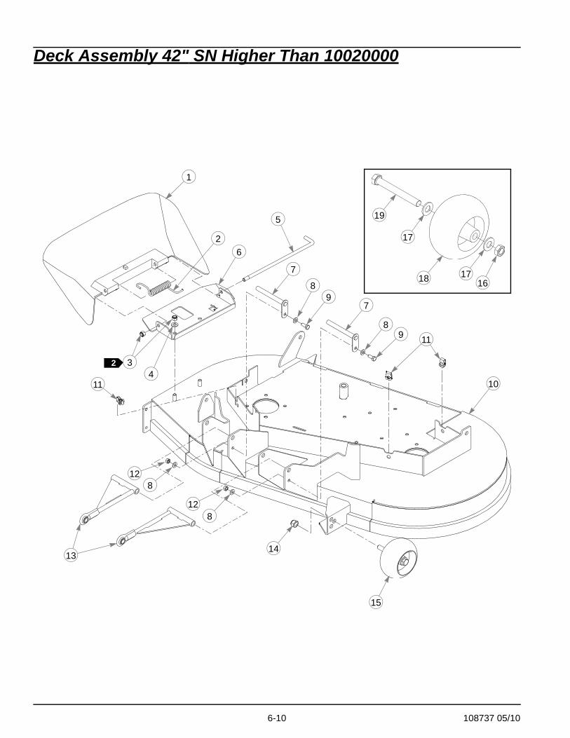
Deck Assembly 42" SN Higher Than 10020000
19
17
171618
11
7
8
7
8
9
9
10
1413
1
2
5
34
6
2
15
128
11
128
108737 05/10 6-11
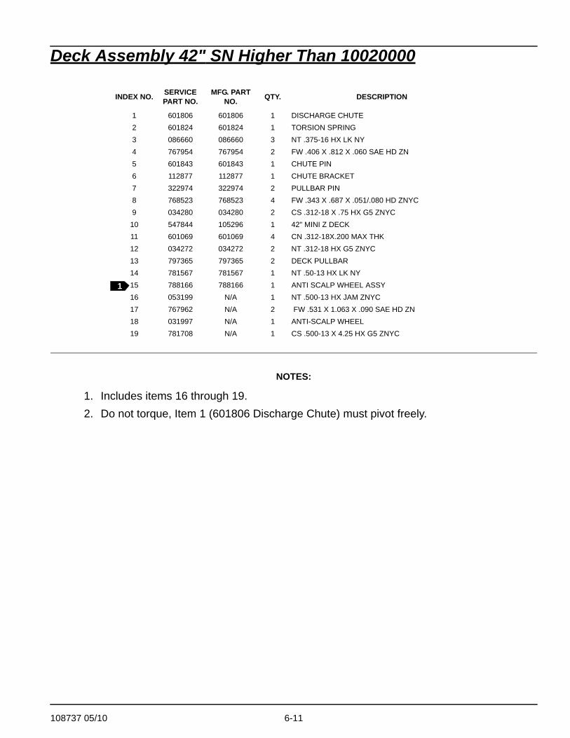
Deck Assembly 42" SN Higher Than 10020000
NOTES:
1. Includes items 16 through 19.2. Do not torque, Item 1 (601806 Discharge Chute) must pivot freely.
INDEX NO. SERVICE PART NO.
MFG. PART NO. QTY. DESCRIPTION
1 601806 601806 1 DISCHARGE CHUTE2 601824 601824 1 TORSION SPRING3 086660 086660 3 NT .375-16 HX LK NY4 767954 767954 2 FW .406 X .812 X .060 SAE HD ZN5 601843 601843 1 CHUTE PIN6 112877 112877 1 CHUTE BRACKET7 322974 322974 2 PULLBAR PIN8 768523 768523 4 FW .343 X .687 X .051/.080 HD ZNYC9 034280 034280 2 CS .312-18 X .75 HX G5 ZNYC
10 547844 105296 1 42" MINI Z DECK11 601069 601069 4 CN .312-18X.200 MAX THK12 034272 034272 2 NT .312-18 HX G5 ZNYC13 797365 797365 2 DECK PULLBAR14 781567 781567 1 NT .50-13 HX LK NY15 788166 788166 1 ANTI SCALP WHEEL ASSY16 053199 N/A 1 NT .500-13 HX JAM ZNYC17 767962 N/A 2 FW .531 X 1.063 X .090 SAE HD ZN18 031997 N/A 1 ANTI-SCALP WHEEL19 781708 N/A 1 CS .500-13 X 4.25 HX G5 ZNYC
1
6-12 108737 05/10
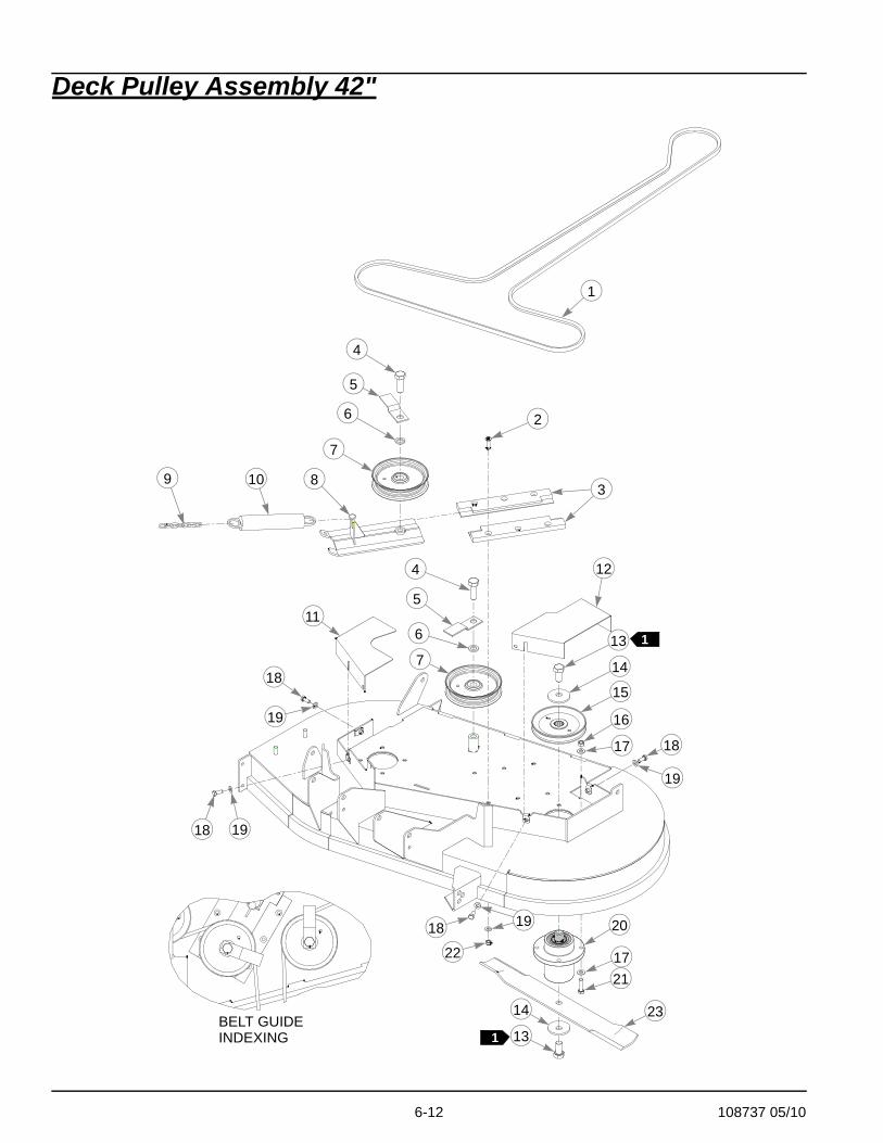
Deck Pulley Assembly 42"
1 13
1
2
4
4
5
6
5
7
7
8
12
113
14
14
15
16
17
17
18
18
18
18
19
19
19
19
20
21
23
22
11
9 10
BELT GUIDEINDEXING
6
3
108737 05/10 6-13
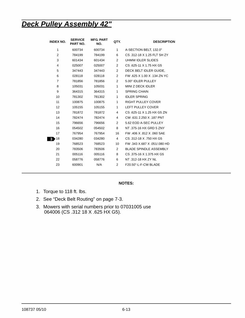
Deck Pulley Assembly 42"
NOTES:
1. Torque to 118 ft. lbs.2. See “Deck Belt Routing” on page 7-3.3. Mowers with serial numbers prior to 07031005 use
064006 (CS .312 18 X .625 HX G5).
INDEX NO. SERVICE PART NO.
MFG. PART NO. QTY. DESCRIPTION
1 600734 600734 1 A-SECTION BELT, 132.0"2 784199 784199 6 CS .312-18 X 1.25 FLT SH ZY3 601434 601434 2 UHMW IDLER SLIDES4 025007 025007 2 CS .625-11 X 1.75 HX G55 347443 347443 2 DECK BELT IDLER GUIDE,6 028118 028118 2 FW .625 X 1.00 X .134 ZN YC7 781856 781856 2 5.00" IDLER PULLEY8 105031 105031 1 MINI Z DECK IDLER9 364315 364315 1 SPRING CHAIN
10 781302 781302 1 IDLER SPRING11 100875 100875 1 RIGHT PULLEY COVER12 105155 105155 1 LEFT PULLEY COVER13 781872 781872 4 CS .625-11 X 1.25 HX G5 ZN14 782474 782474 4 CW .631 2.250 X .187 PNT15 796656 796656 2 5.62 EOD A-SEC PULLEY16 054502 054502 8 NT .375-16 HX GRD 5 ZNY17 767954 767954 16 FW .406 X .812 X .060 SAE18 034280 034280 4 CS .312-18 X .750 HX G519 768523 768523 10 FW .343 X.687 X .051/.080 HD20 783506 783506 2 BLADE SPINDLE ASSEMBLY21 005116 005116 8 CS .375-16 X 1.375 HX G522 058776 058776 6 NT .312-18 HX ZY NL23 600901 N/A 2 F20.50"-L-F-CW BLADE
3
6-14 108737 05/10
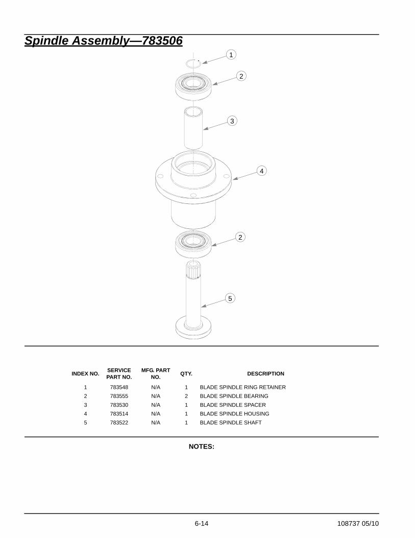
Spindle Assembly—783506
NOTES:
INDEX NO. SERVICE PART NO.
MFG. PART NO. QTY. DESCRIPTION
1 783548 N/A 1 BLADE SPINDLE RING RETAINER2 783555 N/A 2 BLADE SPINDLE BEARING3 783530 N/A 1 BLADE SPINDLE SPACER4 783514 N/A 1 BLADE SPINDLE HOUSING5 783522 N/A 1 BLADE SPINDLE SHAFT
1
2
3
4
2
5

108737 05/10 6-15
This page intentionally left blank.

6-16 108737 05/10

108737 05/10 7-1
Chapter 7 Contents
Deck Installation . . . . . . . . . . . . . . . . . . . . . . . . . . . . . . . . . . . . . . . . 7-2
Deck Belt Routing . . . . . . . . . . . . . . . . . . . . . . . . . . . . . . . . . . . . . . . 7-3
Seat Installation . . . . . . . . . . . . . . . . . . . . . . . . . . . . . . . . . . . . . . . . . 7-4
7-2 108737 05/10
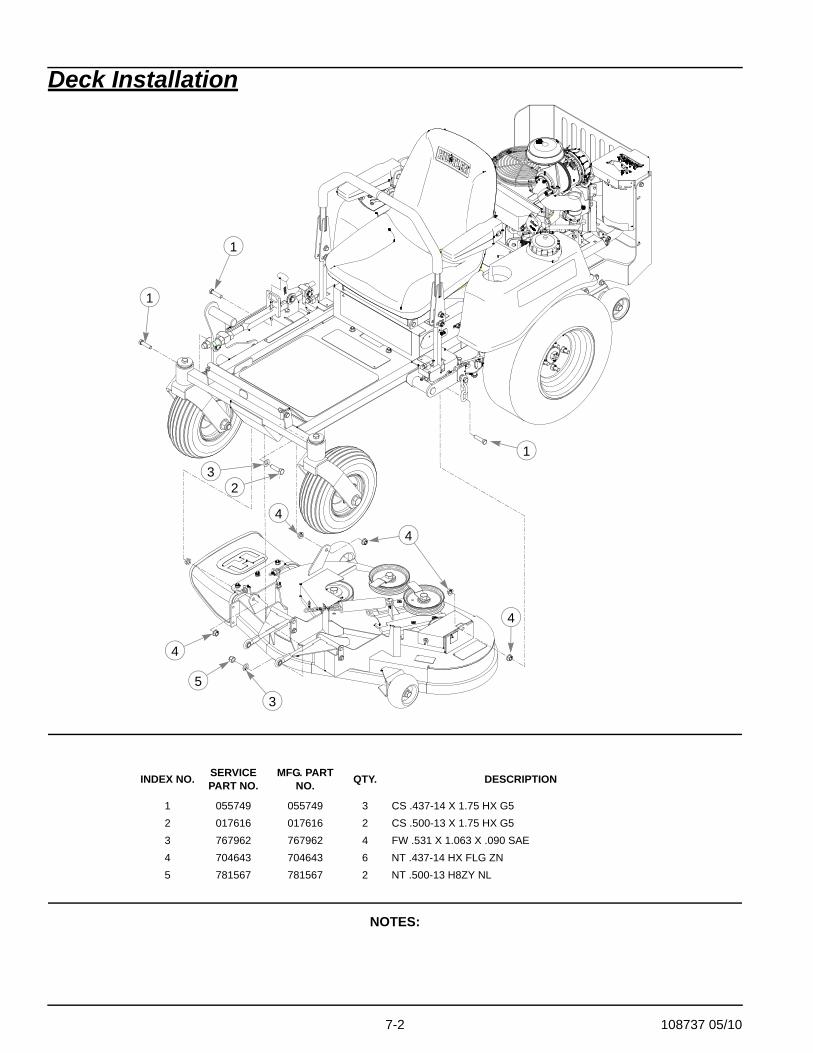
Deck Installation
NOTES:
INDEX NO. SERVICE PART NO.
MFG. PART NO. QTY. DESCRIPTION
1 055749 055749 3 CS .437-14 X 1.75 HX G52 017616 017616 2 CS .500-13 X 1.75 HX G53 767962 767962 4 FW .531 X 1.063 X .090 SAE4 704643 704643 6 NT .437-14 HX FLG ZN5 781567 781567 2 NT .500-13 H8ZY NL
1
1
1
23
3
4
4
4
4
5

108737 05/10 7-3
Deck Belt Routing
NOTES
1. Spring length after tension belt–measured from outside of hook to outside of hook. Tension spring with deck in level position.
2. Route belt as shown.
7-4 108737 05/10
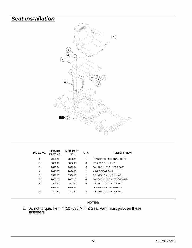
Seat Installation
NOTES:
1. Do not torque, Item 4 (107630 Mini Z Seat Pan) must pivot on these fasteners.
INDEX NO. SERVICE PART NO.
MFG. PART NO. QTY. DESCRIPTION
1 792226 792226 1 STANDARD MICHIGAN SEAT2 086660 086660 3 NT .375-16 HX ZY NL3 767954 767954 3 FW .406 X .812 X .060 SAE4 107630 107630 1 MINI Z SEAT PAN5 052860 052860 2 CS .375-16 X 1.25 HX G56 768523 768523 4 FW .343 X .687 X .051/.080 HD7 034280 034280 4 CS .312-18 X .750 HX G58 793851 793851 2 COMPRESSION SPRING9 036244 036244 2 CS .375-16 X 1.00 HX G5
1
2
2
3
3
35
8
67
91
4

108737 05/10 8-1
Chapter 8 Contents
Tractor Decals . . . . . . . . . . . . . . . . . . . . . . . . . . . . . . . . . . . . . . . . . . 8-2
36" Deck Decals . . . . . . . . . . . . . . . . . . . . . . . . . . . . . . . . . . . . . . . . 8-4
42" Deck Decals . . . . . . . . . . . . . . . . . . . . . . . . . . . . . . . . . . . . . . . . 8-5
8-2 108737 05/10
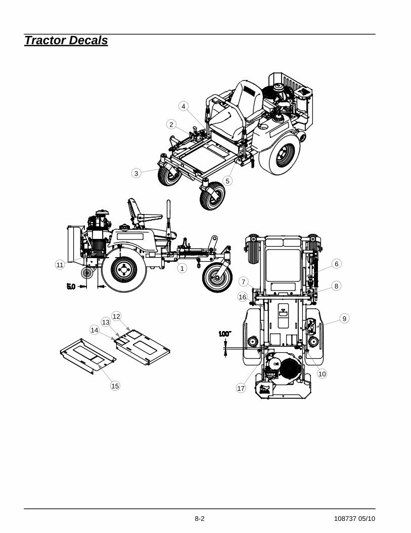
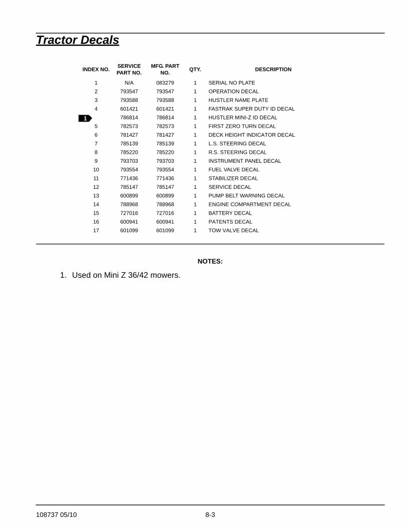
Tractor Decals
1213
14
15
11 1
17
10
9
8
6
16
7
53
2
4
108737 05/10 8-3
Tractor Decals
NOTES:
1. Used on Mini Z 36/42 mowers.
INDEX NO. SERVICE PART NO.
MFG. PART NO. QTY. DESCRIPTION
1 N/A 083279 1 SERIAL NO PLATE2 793547 793547 1 OPERATION DECAL3 793588 793588 1 HUSTLER NAME PLATE4 601421 601421 1 FASTRAK SUPER DUTY ID DECAL
786814 786814 1 HUSTLER MINI-Z ID DECAL5 782573 782573 1 FIRST ZERO TURN DECAL6 781427 781427 1 DECK HEIGHT INDICATOR DECAL7 785139 785139 1 L.S. STEERING DECAL8 785220 785220 1 R.S. STEERING DECAL9 793703 793703 1 INSTRUMENT PANEL DECAL
10 793554 793554 1 FUEL VALVE DECAL11 771436 771436 1 STABILIZER DECAL12 785147 785147 1 SERVICE DECAL13 600899 600899 1 PUMP BELT WARNING DECAL14 788968 788968 1 ENGINE COMPARTMENT DECAL15 727016 727016 1 BATTERY DECAL16 600941 600941 1 PATENTS DECAL17 601099 601099 1 TOW VALVE DECAL
1
8-4 108737 05/10
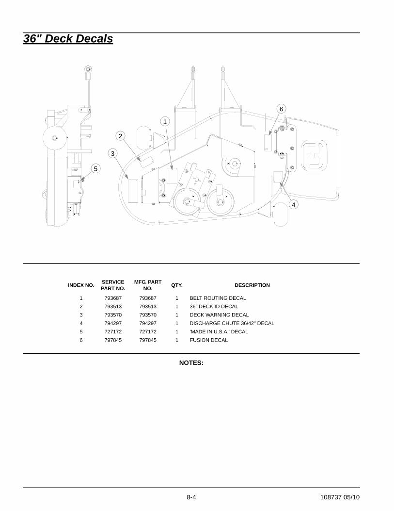
36" Deck Decals
NOTES:
INDEX NO. SERVICE PART NO.
MFG. PART NO. QTY. DESCRIPTION
1 793687 793687 1 BELT ROUTING DECAL2 793513 793513 1 36" DECK ID DECAL3 793570 793570 1 DECK WARNING DECAL4 794297 794297 1 DISCHARGE CHUTE 36/42" DECAL5 727172 727172 1 'MADE IN U.S.A.' DECAL6 797845 797845 1 FUSION DECAL
1
2
3
4
5
6
108737 05/10 8-5
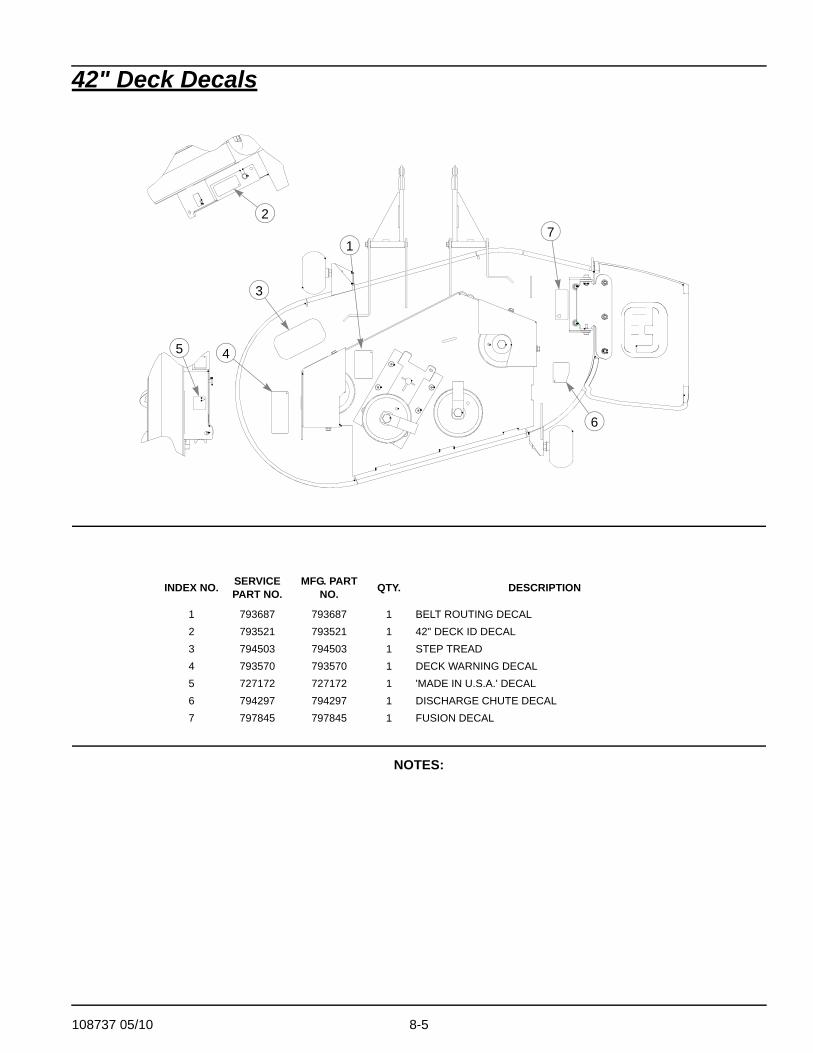
42" Deck Decals
NOTES:
INDEX NO. SERVICE PART NO.
MFG. PART NO. QTY. DESCRIPTION
1 793687 793687 1 BELT ROUTING DECAL2 793521 793521 1 42" DECK ID DECAL3 794503 794503 1 STEP TREAD4 793570 793570 1 DECK WARNING DECAL5 727172 727172 1 'MADE IN U.S.A.' DECAL6 794297 794297 1 DISCHARGE CHUTE DECAL7 797845 797845 1 FUSION DECAL
1
3
45
6
27

8-6 108737 05/10

108737 05/10 9-1
Chapter 9 Contents
Assembly Pictures and Aids . . . . . . . . . . . . . . . . . . . . . . . . . . . . . . . 9-2
Connections for all models:. . . . . . . . . . . . . . . . . . . . . . . . . . . 9-2Fuel tanks and fuel line routing: . . . . . . . . . . . . . . . . . . . . . . . 9-4
Maintenance & Adjustment Safety. . . . . . . . . . . . . . . . . . . . . . . . . . . 9-5
Maintenance . . . . . . . . . . . . . . . . . . . . . . . . . . . . . . . . . . . . . . . . . . . 9-9
Recommended service procedure . . . . . . . . . . . . . . . . . . . . 9-19Overservicing . . . . . . . . . . . . . . . . . . . . . . . . . . . . . . . . . . . . 9-20
Adjustments . . . . . . . . . . . . . . . . . . . . . . . . . . . . . . . . . . . . . . . . . . . 9-26
9-2 108737 05/10
Assembly Pictures and Aids
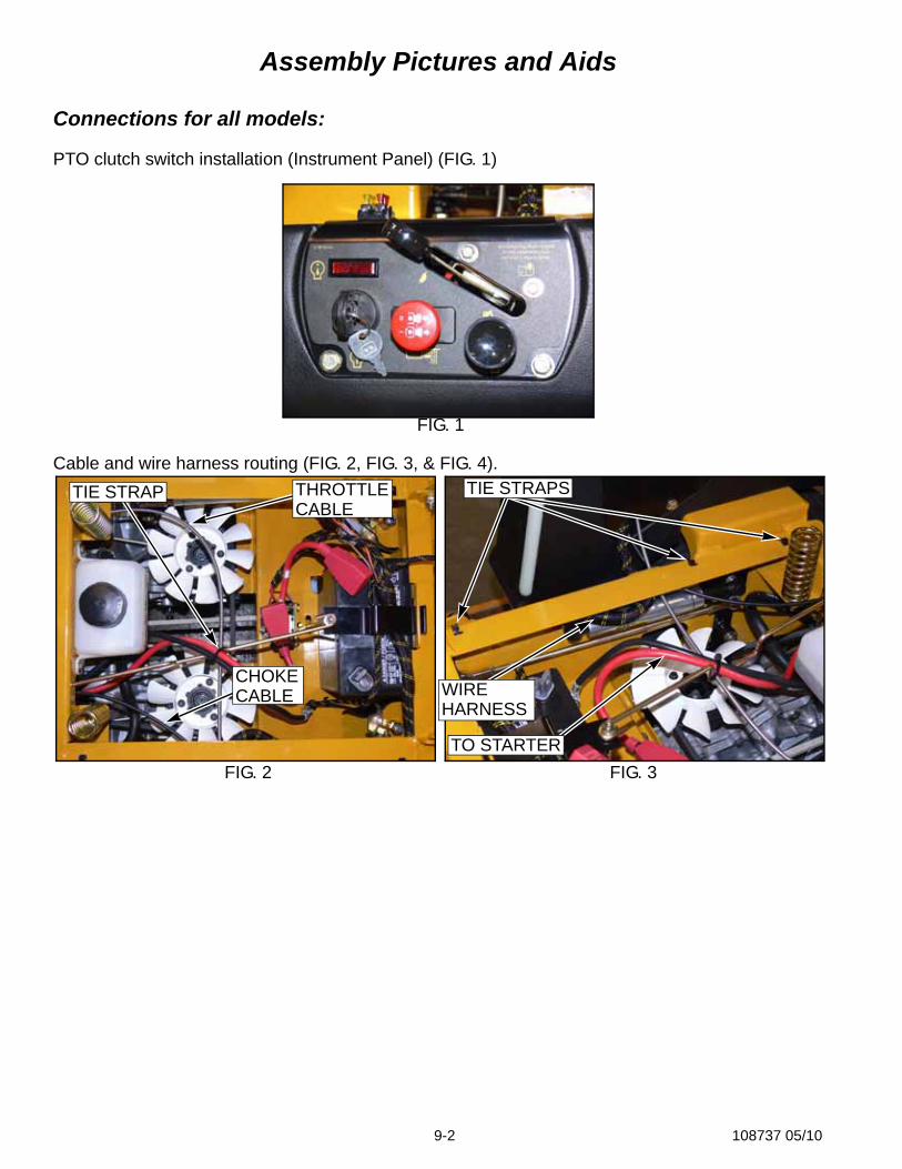
Connections for all models:
PTO clutch switch installation (Instrument Panel) (FIG. 1)
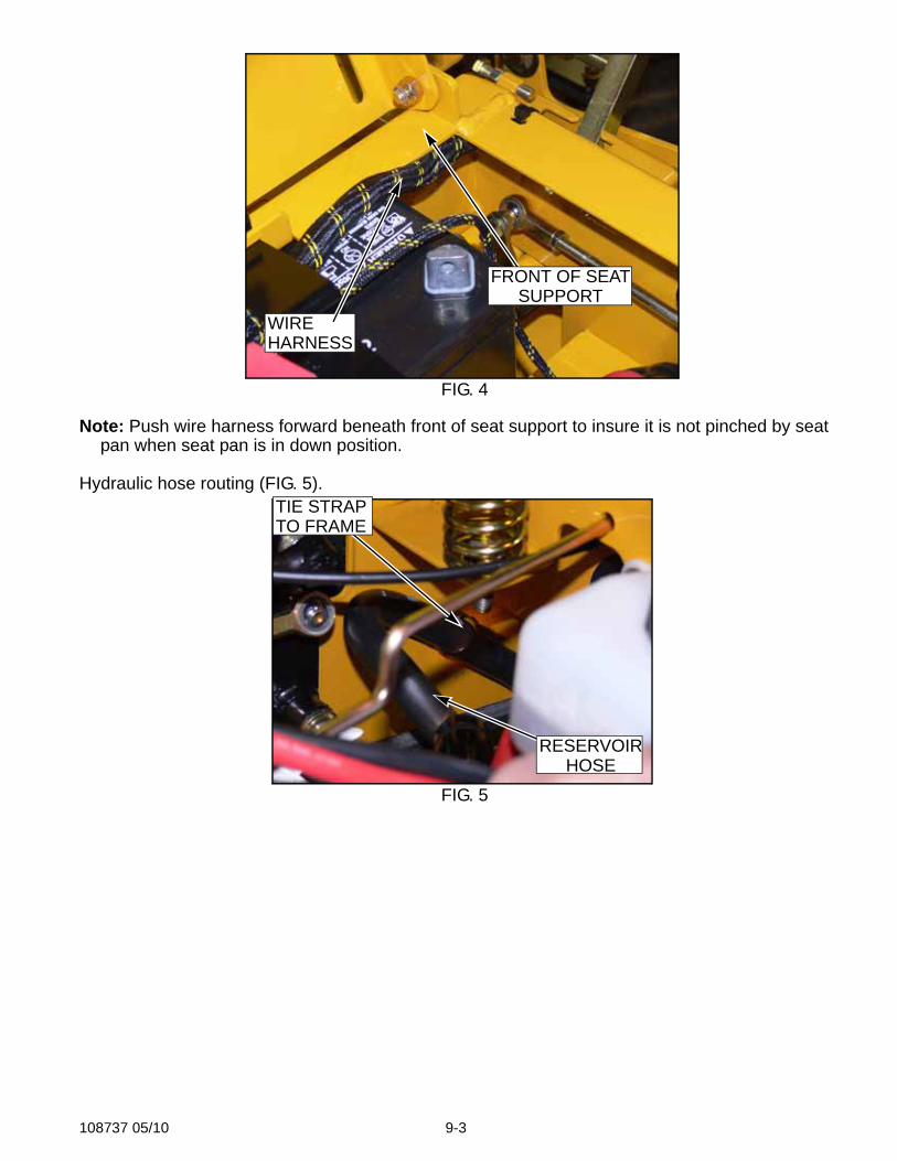
Cable and wire harness routing (FIG. 2, FIG. 3, & FIG. 4).
FIG. 1
FIG. 2 FIG. 3
THROTTLETIE STRAPCABLE
CHOKECABLE
TO STARTER
TIE STRAPS
WIREHARNESS
108737 05/10 9-3
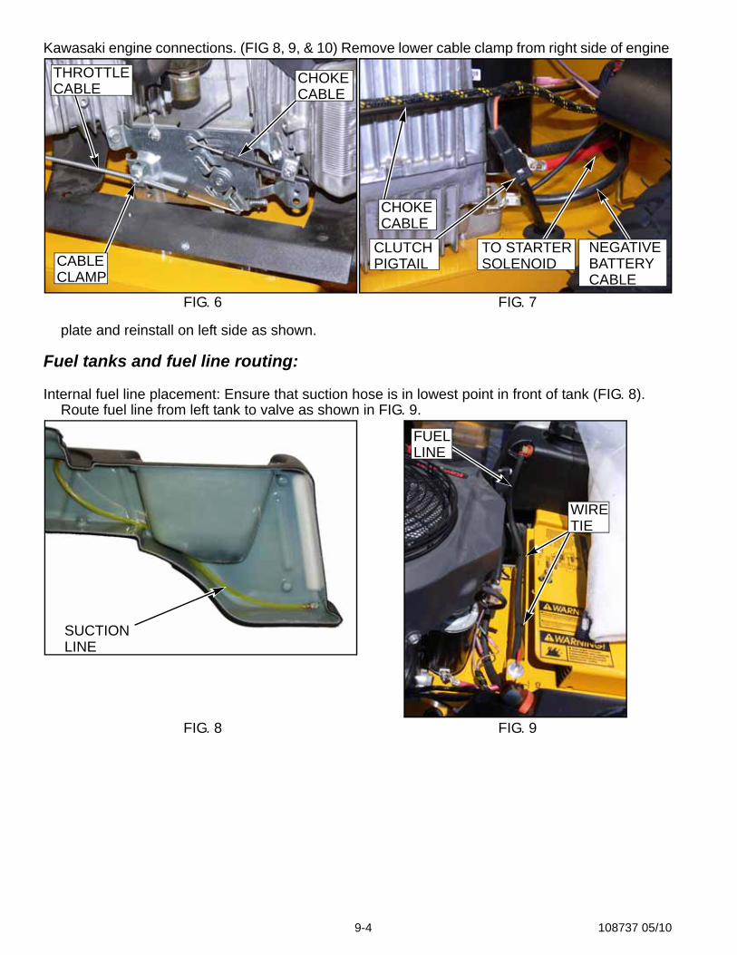
Note: Push wire harness forward beneath front of seat support to insure it is not pinched by seat pan when seat pan is in down position.
Hydraulic hose routing (FIG. 5).
FIG. 4
FIG. 5
WIREHARNESS
FRONT OF SEATSUPPORT
TIE STRAP
RESERVOIRHOSE
TO FRAME
9-4 108737 05/10
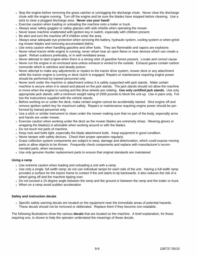
Kawasaki engine connections. (FIG 8, 9, & 10) Remove lower cable clamp from right side of engine
plate and reinstall on left side as shown.
Fuel tanks and fuel line routing:
Internal fuel line placement: Ensure that suction hose is in lowest point in front of tank (FIG. 8). Route fuel line from left tank to valve as shown in FIG. 9.
FIG. 6 FIG. 7
FIG. 8 FIG. 9
THROTTLECABLE
CHOKECABLE
CABLECLAMP
CHOKECABLE
TO STARTERSOLENOID
NEGATIVEBATTERYCABLE
CLUTCHPIGTAIL
SUCTIONLINE
WIRETIE
FUELLINE

108737 05/10 9-5
Maintenance & Adjustment Safety
This safety alert symbol is used to call attention to a message intended to provide a reasonable degree of PERSONAL SAFETY for operators and other persons during the normal operation and servicing of this equipment.
DANGER – denotes immediate hazards which WILL result in severe personal injury or death.WARNING - denotes a hazard or unsafe practice which COULD result in severe personal injury or death.This manual uses two other words to highlight information. IMPORTANT calls attention to special mechanical informa-
tion and NOTE: emphasizes general information worthy of special attention.All operators should read this manual, or be instructed about safe operating and maintenance procedures. This is
the owner’s responsibility.Improper use or maintenance by the operator, mechanic, or owner can result in injury. To reduce the poten-
tial for injury, comply with these safety instructions and always pay attention to the safety alert s symbol, which means DANGER or WARNING - “personal safety instructions.” Failure to comply with the instructions may result in personal injury or death.
Incorrect usage of this machine may result in severe injury. Personnel operating and maintaining it should be trained in the proper use and should read the manuals completely and thoroughly before attempting to set-up, operate, adjust, or service this machine.
The Quick Reference Decals, located in front of and to the right of the seat, are designed to give the operator/mechanic brief information needed in the daily operation and service of the machine. These decals are not intended to be used in place of this manual but instead is to be used as an extension of this manual. These decals should not be removed or obliterated. Replace these decals if they become unreadable.
It is the owner’s responsibility to make certain that the operator/mechanic reads and understands this manual and all decals before operating this machine. It is also the owner’s responsibility to make certain that the operator/mechanic is a qualified and physically able individual, properly trained in the operation of this equipment. Local regula-tions may restrict the age of the operator/mechanic.
The owner should also ensure that the operator/mechanic knows that they are responsible for their own safety as well as the safety of other persons within the vicinity. Remember, the operator/mechanic is responsible for accidents or hazards occurring to other people or their property.
Safe maintenance & adjustment practicesThis product is capable of amputating hands and feet and throwing objects. Always follow all safety instructions to
avoid serious injury or death.
s Unless specifically required, DO NOT have engine running when servicing or making adjustments to tractor. Place control levers in the park brake position, disengage deck clutch, remove ignition switch key and disconnect the negative battery cable. Repairs or maintenance requiring engine power should be performed by trained per-sonnel only. To prevent carbon monoxide poisoning, be sure proper ventilation is available when engine must be operated in an enclosed area.
s Follow daily and weekly checklists, making sure hoses are tightly secured and bolts are tightened.s Keep your machine clean and remove any deposits of trash and clippings, which can cause engine fires and
hydraulic overheating as well as excessive belt wear. Clean up oil or fuel spillage. Allow machine to cool before storing.
s Clean flammable material from machine. Prevent fires by keeping engine compartment, battery, hydraulic lines, fuel line, fuel tank and operator’s station clean of accumulated trash, grass clippings, and other debris. Always clean up spilled fuel and oil.
s Always wear adequate ear protection, such as earplugs, when operating this equipment as prolonged exposure to uncomfortable or loud noises can cause impairment or loss of hearing. Do not wear radios or music headphones while operating the machinery. Safe operation requires your full attention.
s Never put hands or feet under any part of the machine while it is running.s Except when changing or checking belt, always keep belt covers on mower for safety as well as cleanliness.
9-6 108737 05/10
s Stop the engine before removing the grass catcher or unclogging the discharge chute. Never clear the discharge chute with the engine running. Turn off the engine and be sure the blades have stopped before cleaning. Use a stick to clear a plugged discharge area. Never use your hand!
s Exercise caution when loading or unloading the machine onto a trailer or truck.s Always wear safety goggles or safety glasses with side shields when operating the mower.s Never leave machine unattended with ignition key in switch, especially with children present. s Be alert and turn the machine off if children enter the area.s Always wear adequate eye protection when servicing the battery, hydraulic system, cooling system or when grind-
ing mower blades and removing accumulated debris. s Use extra caution when handling gasoline and other fuels. They are flammable and vapors are explosive.s Never refuel tractor while engine is running; never refuel near an open flame or near devices which can create a
spark. Refuel outdoors preferably, or in well ventilated areas.s Never attempt to start engine when there is a strong odor of gasoline fumes present. Locate and correct cause.s Never run the engine in an enclosed area unless exhaust is vented to the outside. Exhaust gases contain carbon
monoxide which is odorless and deadly poison.s Never attempt to make any adjustments or repairs to the tractor drive system, mower deck or any attachment
while the tractor engine is running or deck clutch is engaged. Repairs or maintenance requiring engine power should be performed by trained personnel only.
s Never work under the machine or attachment unless it is safely supported with jack stands. Make certain machine is secure when it is raised and placed on the jack stands. The jack stands should not allow the machine to move when the engine is running and the drive wheels are rotating. Use only certified jack stands. Use only appropriate jack stands, with a minimum weight rating of 2000 pounds to block the unit up. Use in pairs only. Fol-low the instructions supplied with the vehicle stands.
s Before working on or under the deck, make certain engine cannot be accidentally started. Shut engine off and remove ignition switch key for maximum safety. Repairs or maintenance requiring engine power should be per-formed by trained personnel only.
s Use a stick or similar instrument to clean under the mower making sure that no part of the body, especially arms and hands are under mower.
s Exercise caution when working under the deck as the mower blades are extremely sharp. Wearing gloves or wrapping the blade(s) is advisable when working around or with the blades.
s Do not touch hot parts of machine.s Keep nuts and bolts tight, especially the blade attachment bolts. Keep equipment in good condition.s Never tamper with safety devices. Check their proper operation regularly.s Grass collection system components are subject to wear, damage and deterioration, which could expose moving
parts or allow objects to be thrown. Frequently check components and replace with manufacturer’s recom-mended parts, when necessary.
s Use only genuine Hustler replacement parts to ensure that original standards are maintained
Using a ramps Use extreme caution when loading and unloading a unit with a ramp.s Use only a single, full width ramp; do not use individual ramps for each side of the unit. Having a full width ramp
provides a surface for the tractor frame to contact if the unit starts to tip backwards. It also reduces the risk of a wheel going off and the machine tipping over.
s Do not exceed a 15 degree angle between the ramp and the ground or between the ramp and the trailer or truck.s When on a ramp avoid sudden acceleration
Safety and instruction decals
s Specific safety warning decals are located on the equipment near the immediate areas of potential hazards. These decals should not be removed or obliterated. Replace them if they become non-readable.
The following illustrations show the various decals that are located on the machine. A brief explanation, for those requiring one, is shown to help the operator understand the meanings of these decals.
108737 05/10 9-7
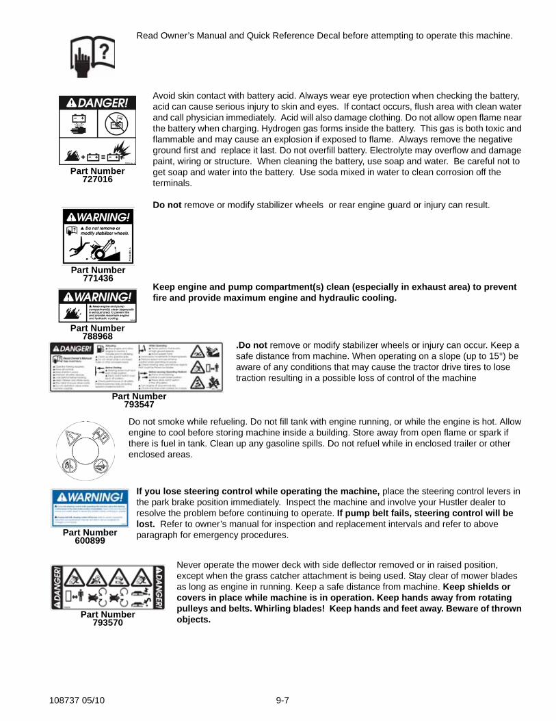
Read Owner’s Manual and Quick Reference Decal before attempting to operate this machine.
Avoid skin contact with battery acid. Always wear eye protection when checking the battery, acid can cause serious injury to skin and eyes. If contact occurs, flush area with clean water and call physician immediately. Acid will also damage clothing. Do not allow open flame near the battery when charging. Hydrogen gas forms inside the battery. This gas is both toxic and flammable and may cause an explosion if exposed to flame. Always remove the negative ground first and replace it last. Do not overfill battery. Electrolyte may overflow and damage paint, wiring or structure. When cleaning the battery, use soap and water. Be careful not to get soap and water into the battery. Use soda mixed in water to clean corrosion off the terminals.
Do not remove or modify stabilizer wheels or rear engine guard or injury can result.
Keep engine and pump compartment(s) clean (especially in exhaust area) to prevent fire and provide maximum engine and hydraulic cooling.
.Do not remove or modify stabilizer wheels or injury can occur. Keep a safe distance from machine. When operating on a slope (up to 15°) be aware of any conditions that may cause the tractor drive tires to lose traction resulting in a possible loss of control of the machine
Do not smoke while refueling. Do not fill tank with engine running, or while the engine is hot. Allow engine to cool before storing machine inside a building. Store away from open flame or spark if there is fuel in tank. Clean up any gasoline spills. Do not refuel while in enclosed trailer or other enclosed areas.
If you lose steering control while operating the machine, place the steering control levers in the park brake position immediately. Inspect the machine and involve your Hustler dealer to resolve the problem before continuing to operate. If pump belt fails, steering control will be lost. Refer to owner’s manual for inspection and replacement intervals and refer to above paragraph for emergency procedures.
Never operate the mower deck with side deflector removed or in raised position, except when the grass catcher attachment is being used. Stay clear of mower blades as long as engine in running. Keep a safe distance from machine. Keep shields or covers in place while machine is in operation. Keep hands away from rotating pulleys and belts. Whirling blades! Keep hands and feet away. Beware of thrown objects.
Part Number727016
Part Number771436
Part Number788968
Part Number793547
Part Number600899
Part Number793570

9-8 108737 05/10
Never operate the mower deck with side deflector removed or in raised position, except when the grass catcher attachment is being used. Stay clear of mower blades as long as engine in running. Beware of thrown objects.
Part Number727438
108737 05/10 9-9
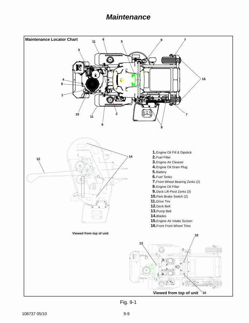
Maintenance
Fig. 9-1
1214
Viewed from top of unit
13
Viewed from top of unit
1
3
8
1511
11
10
10
6
6
5 7
7
16
2
9
4
1.Engine Oil Fill & Dipstick2.Fuel Filter3.Engine Air Cleaner4.Engine Oil Drain Plug5.Battery6.Fuel Tanks7.Front Wheel Bearing Zerks (2)8.Engine Oil Filter9.Deck Lift Pivot Zerks (3)
10.Park Brake Switch (2)11.Drive Tire 12.Deck Belt13.Pump Belt14.Blades15.Engine Air Intake Screen16.Front Front Wheel Tires
Maintenance Locator Chart 9
9-10 108737 05/10
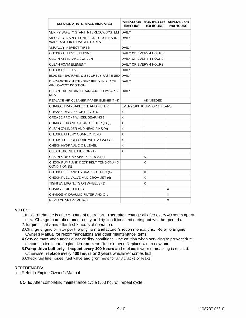
NOTES:1.Initial oil change is after 5 hours of operation. Thereafter, change oil after every 40 hours opera-
tion. Change more often under dusty or dirty conditions and during hot weather periods.2.Torque initially and after first 2 hours of operation.3.Change engine oil filter per the engine manufacturer’s recommendations. Refer to Engine
Owner’s Manual for recommendations and other maintenance items.4.Service more often under dusty or dirty conditions. Use caution when servicing to prevent dust
contamination in the engine. Do not clean filter element. Replace with a new one.5.Pump drive belt only - Inspect every 100 hours and replace if worn or cracking is noticed.
Otherwise, replace every 400 hours or 2 years whichever comes first.6.Check fuel line hoses, fuel valve and grommets for any cracks or leaks
REFERENCES:a ---Refer to Engine Owner’s Manual
NOTE: After completing maintenance cycle (500 hours), repeat cycle.
SERVICE ATINTERVALS INDICATED WEEKLY OR 50HOURS
MONTHLY OR 100 HOURS
ANNUALL OR 500 HOURS
VERIFY SAFETY START INTERLOCK SYSTEM DAILY
VISUALLY INSPECT UNIT FOR LOOSE HARD-WARE AND/OR DAMAGED PARTS
DAILY
VISUALLY INSPECT TIRES DAILY
CHECK OIL LEVEL, ENGINE DAILY OR EVERY 4 HOURS
CLEAN AIR INTAKE SCREEN DAILY OR EVERY 4 HOURS
CLEAN FOAM ELEMENT DAILY OR EVERY 4 HOURS
CHECK FUEL LEVEL DAILY
BLADES - SHARPEN & SECURELY FASTENED DAILY
DISCHARGE CHUTE - SECURELY IN PLACE &IN LOWEST POSITION
DAILY
CLEAN ENGINE AND TRANSAXLECOMPART-MENT
DAILY
REPLACE AIR CLEANER PAPER ELEMENT (4) AS NEEDED
CHANGE TRANSAXLE OIL AND FILTER EVERY 200 HOURS OR 2 YEARS
GREASE DECK HEIGHT PIVOTS X
GREASE FRONT WHEEL BEARINGS X
CHANGE ENGINE OIL AND FILTER (1) (3) X
CLEAN CYLINDER AND HEAD FINS (A) X
CHECK BATTERY CONNECTIONS X
CHECK TIRE PRESSURE WITH A GAUGE X
CHECK HYDRAULIC OIL LEVEL X
CLEAN ENGINE EXTERIOR (A) X
CLEAN & RE GAP SPARK PLUGS (A) X
CHECK PUMP AND DECK BELT TENSIONAND CONDITION (5)
X
CHECK FUEL AND HYDRAULIC LINES (6) X
CHECK FUEL VALVE AND GROMMET (6) X
TIGHTEN LUG NUTS ON WHEELS (2) X
CHANGE FUEL FILTER X
CHANGE HYDRAULIC FILTER AND OIL X
REPLACE SPARK PLUGS X
108737 05/10 9-11
IntroductionRegular maintenance is the best prevention for costly downtime or expensive, premature repair. The following
pages contain suggested maintenance information and schedules which the operator should follow on a routine basis. Remain alert for unusual noises, they could be signaling a problem. Visually inspect the machine for any abnormal
wear or damage. A good time to detect potential problems is while performing scheduled maintenance service. Cor-recting the problem as quickly as possible is the best insurance.
Clear away heavy build-up of grease, oil and dirt, especially in the engine and under the seat platform areas; minute dust particles are abrasive to close-tolerance engine and hydraulic assemblies.
Daily inspect mower for grass clippings and wire and string tangles. The underside of the mower deck will collect a build-up of grass clippings and dirt, especially when grass is wet or has high moisture content. This build-up will harden, restricting blade and air movement and will probably show a poorer quality of cutting Therefore it should be removed routinely.
To do this it will be necessary to raise and block the deck, using jack stands or blocks, in the full up position and scrape the build-up from underneath.
Some repairs require the assistance of a trained service mechanic and should not be attempted by unskilled person-nel. Consult your Hustler service center when assistance is needed.
Torque values
WARNING: Particular attention must be given to tightening the drive wheel lug nuts and blade spindle bolts. Failure to correctly torque these items may result in the loss of a wheel or blade, which can cause serious damage or personal injury.
Torque values are given below:Ft.-lbs. Nm
Wheel (lug) nuts ......................65-75 .... 88.14-101.7Blade spindle bolt top............... 118.......... 160.01Blade spindle bolt bottom......... 118.......... 160.01
Lug nuts only - It is recommended that these be checked after the first 2 hours of operation, initially, every 50 hoursand following removal for repair or replacement.
For all other torques refer to the torque chart located elsewhere in this manual.For engine torque values, see engine owner’s manual.
TiresIt is important for level mowing that the tires have the same amount of air pressure. The recommended pressure
are:Drive wheels................8-12 psi (55-69 KPa)Front wheels................8-12 psi (55-69 KPa)
Solid fill tires are not recommended for Hustler turf equipment. On any machine, with solid filled tires, the war-ranty claim will be denied.
WARNING: Explosive separation of a tire and rim can cause serious injury or death.
Do not attempt to mount a tire without the proper equipment and experience to perform the task. Always maintain the correct tire pressure and never over inflate. Never weld or heat a wheel and tire assembly as an explosion may occur. Welding can weaken or deform a wheel. When inflating tires stand to one side and not in front of or over the tire assembly. Check tires for low pressure, blemishes, damaged rims or missing lug bolts and nuts.
Lubrication1.Grease the front wheel bearings per the Maintenance Schedule. Use SAE multi-purpose
grease.2.Grease the four deck lift pivots, located to the side of the operator’s footrest per the Maintenance
Schedule. Use SAE multi-purpose grease.
9-12 108737 05/10
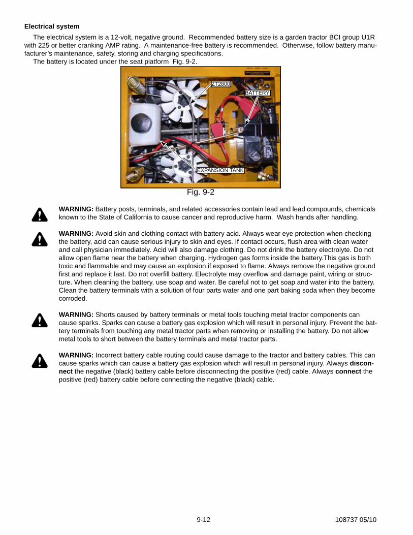
Electrical systemThe electrical system is a 12-volt, negative ground. Recommended battery size is a garden tractor BCI group U1R
with 225 or better cranking AMP rating. A maintenance-free battery is recommended. Otherwise, follow battery manu-facturer’s maintenance, safety, storing and charging specifications.
The battery is located under the seat platform Fig. 9-2.
WARNING: Battery posts, terminals, and related accessories contain lead and lead compounds, chemicals known to the State of California to cause cancer and reproductive harm. Wash hands after handling.
WARNING: Avoid skin and clothing contact with battery acid. Always wear eye protection when checking the battery, acid can cause serious injury to skin and eyes. If contact occurs, flush area with clean water and call physician immediately. Acid will also damage clothing. Do not drink the battery electrolyte. Do not allow open flame near the battery when charging. Hydrogen gas forms inside the battery.This gas is both toxic and flammable and may cause an explosion if exposed to flame. Always remove the negative ground first and replace it last. Do not overfill battery. Electrolyte may overflow and damage paint, wiring or struc-ture. When cleaning the battery, use soap and water. Be careful not to get soap and water into the battery. Clean the battery terminals with a solution of four parts water and one part baking soda when they become corroded.
WARNING: Shorts caused by battery terminals or metal tools touching metal tractor components can cause sparks. Sparks can cause a battery gas explosion which will result in personal injury. Prevent the bat-tery terminals from touching any metal tractor parts when removing or installing the battery. Do not allow metal tools to short between the battery terminals and metal tractor parts.
WARNING: Incorrect battery cable routing could cause damage to the tractor and battery cables. This can cause sparks which can cause a battery gas explosion which will result in personal injury. Always discon-nect the negative (black) battery cable before disconnecting the positive (red) cable. Always connect the positive (red) battery cable before connecting the negative (black) cable.
Fig. 9-2
ZT2800BATTERY
EXPANSION TANK
108737 05/10 9-13
Common circuit failures are usually caused by shorting, corroded or dirty terminals; loose connections, defective wire insulation or broken wires. Switches, solenoids and ignition components may also fail, causing a shorted or open circuit.
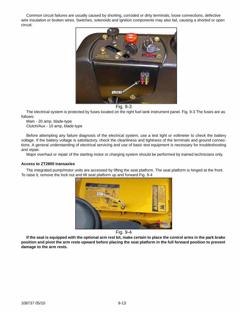
The electrical system is protected by fuses located on the right fuel tank instrument panel. Fig. 9-3 The fuses are as follows:
Main - 20 amp, blade-typeClutch/Aux - 10 amp, blade-type
Before attempting any failure diagnosis of the electrical system, use a test light or voltmeter to check the batteryvoltage. If the battery voltage is satisfactory, check the cleanliness and tightness of the terminals and ground connec-tions. A general understanding of electrical servicing and use of basic test equipment is necessary for troubleshootingand repair.
Major overhaul or repair of the starting motor or charging system should be performed by trained technicians only.
Access to ZT2800 transaxlesThe integrated pump/motor units are accessed by lifting the seat platform. The seat platform is hinged at the front.
To raise it, remove the lock nut and tilt seat platform up and forward.Fig. 9-4
If the seat is equipped with the optional arm rest kit, make certain to place the control arms in the park brake position and pivot the arm rests upward before placing the seat platform in the full forward position to prevent damage to the arm rests.
Fig. 9-3
Fig. 9-4
FUSES
NUT
9-14 108737 05/10
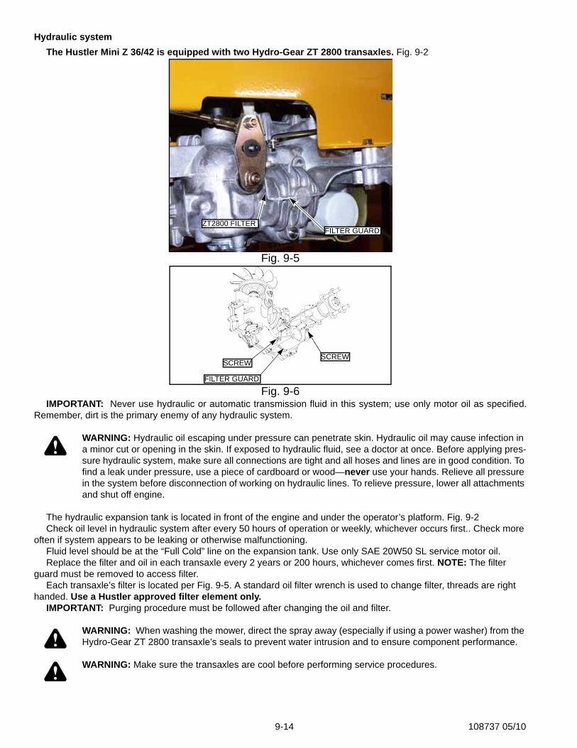
Hydraulic systemThe Hustler Mini Z 36/42 is equipped with two Hydro-Gear ZT 2800 transaxles. Fig. 9-2
IMPORTANT: Never use hydraulic or automatic transmission fluid in this system; use only motor oil as specified.Remember, dirt is the primary enemy of any hydraulic system.
WARNING: Hydraulic oil escaping under pressure can penetrate skin. Hydraulic oil may cause infection in a minor cut or opening in the skin. If exposed to hydraulic fluid, see a doctor at once. Before applying pres-sure hydraulic system, make sure all connections are tight and all hoses and lines are in good condition. To find a leak under pressure, use a piece of cardboard or wood—never use your hands. Relieve all pressure in the system before disconnection of working on hydraulic lines. To relieve pressure, lower all attachments and shut off engine.
The hydraulic expansion tank is located in front of the engine and under the operator’s platform. Fig. 9-2Check oil level in hydraulic system after every 50 hours of operation or weekly, whichever occurs first.. Check more
often if system appears to be leaking or otherwise malfunctioning.Fluid level should be at the “Full Cold” line on the expansion tank. Use only SAE 20W50 SL service motor oil. Replace the filter and oil in each transaxle every 2 years or 200 hours, whichever comes first. NOTE: The filter
guard must be removed to access filter.Each transaxle’s filter is located per Fig. 9-5. A standard oil filter wrench is used to change filter, threads are right
handed. Use a Hustler approved filter element only.IMPORTANT: Purging procedure must be followed after changing the oil and filter.
WARNING: When washing the mower, direct the spray away (especially if using a power washer) from the Hydro-Gear ZT 2800 transaxle’s seals to prevent water intrusion and to ensure component performance.
WARNING: Make sure the transaxles are cool before performing service procedures.
Fig. 9-5
Fig. 9-6
FILTER GUARDZT2800 FILTER
FILTER GUARD
SCREWSCREW
108737 05/10 9-15
Fluid changing procedure1.Park the unit on a level surface. Place control levers in the park brake position, disengage deck
clutch, remove ignition switch key and disconnect negative battery cable.2.Remove the three 1/4” filter guard screws and filter guard. Clean any loose debris from around
the filter Fig. 9-63.Place an oil drain pan beneath the oil filter and remove the oil filter from the transaxle.4.After the oil has been drained, wipe the filter base surface off and apply a film of new oil to the
gasket of the new replacement filter.5.Install the new filter by hand, turn 3/4 to one full turn after the filter gasket contacts the filter base
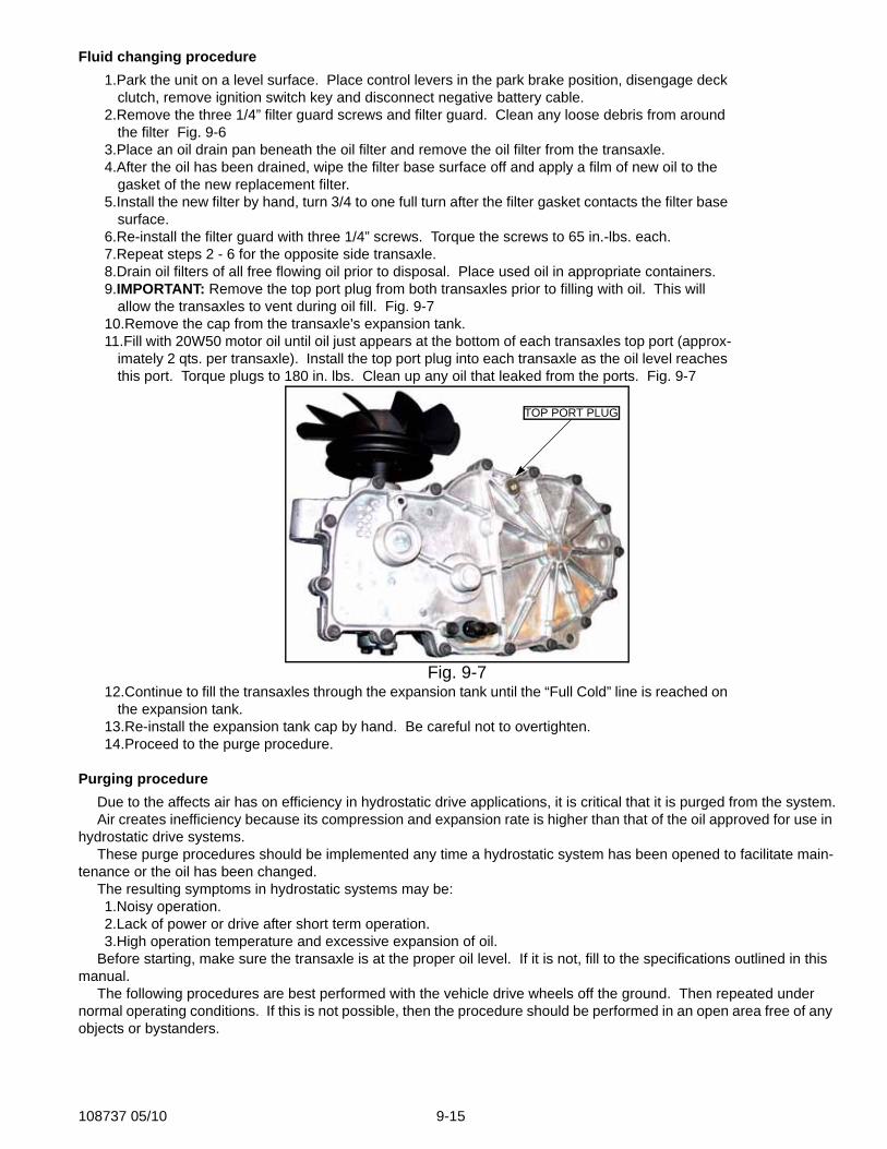
surface.6.Re-install the filter guard with three 1/4” screws. Torque the screws to 65 in.-lbs. each.7.Repeat steps 2 - 6 for the opposite side transaxle.8.Drain oil filters of all free flowing oil prior to disposal. Place used oil in appropriate containers.9.IMPORTANT: Remove the top port plug from both transaxles prior to filling with oil. This will
allow the transaxles to vent during oil fill. Fig. 9-710.Remove the cap from the transaxle's expansion tank.11.Fill with 20W50 motor oil until oil just appears at the bottom of each transaxles top port (approx-
imately 2 qts. per transaxle). Install the top port plug into each transaxle as the oil level reaches this port. Torque plugs to 180 in. lbs. Clean up any oil that leaked from the ports. Fig. 9-7
12.Continue to fill the transaxles through the expansion tank until the “Full Cold” line is reached on the expansion tank.
13.Re-install the expansion tank cap by hand. Be careful not to overtighten.14.Proceed to the purge procedure.
Purging procedureDue to the affects air has on efficiency in hydrostatic drive applications, it is critical that it is purged from the system.Air creates inefficiency because its compression and expansion rate is higher than that of the oil approved for use in
hydrostatic drive systems.These purge procedures should be implemented any time a hydrostatic system has been opened to facilitate main-
tenance or the oil has been changed.The resulting symptoms in hydrostatic systems may be:1.Noisy operation.2.Lack of power or drive after short term operation.3.High operation temperature and excessive expansion of oil.
Before starting, make sure the transaxle is at the proper oil level. If it is not, fill to the specifications outlined in this manual.
The following procedures are best performed with the vehicle drive wheels off the ground. Then repeated under normal operating conditions. If this is not possible, then the procedure should be performed in an open area free of any objects or bystanders.
Fig. 9-7
TOP PORT PLUG
9-16 108737 05/10
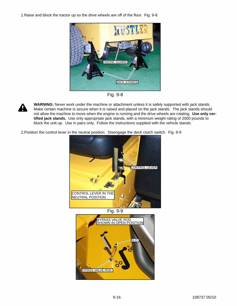
1.Raise and block the tractor up so the drive wheels are off of the floor. Fig. 9-8
WARNING: Never work under the machine or attachment unless it is safely supported with jack stands. Make certain machine is secure when it is raised and placed on the jack stands. The jack stands should not allow the machine to move when the engine is running and the drive wheels are rotating. Use only cer-tified jack stands. Use only appropriate jack stands, with a minimum weight rating of 2000 pounds to block the unit up. Use in pairs only. Follow the instructions supplied with the vehicle stands.
2.Position the control lever in the neutral position. Disengage the deck clutch switch. Fig. 9-9
Fig. 9-8
Fig. 9-9
JACK STANDS
ENGINE GUARD
CONTROL LEVER IN THENEUTRAL POSITION
CONTROL LEVER
BYPASS VALVE ROD SHOWN IN OPEN POSITION
SLOT
BYPASS VALVE ROD
108737 05/10 9-17
3.With the bypass valve open and the engine running, slowly move the directional control in both forward and reverse directions (5 or 6 times). Fig. 9-10
4.With the bypass valve closed and the engine running, slowly move the control lever in both for-ward and reverse directions (5 or 6 times). Check the oil level, and add oil as required after stopping the engine.
5.It may be necessary to repeat Steps 3 and 4 until all the air is completely purged from the sys-tem. When the transaxle operates at normal noise levels and moves smoothly forward and reverse at normal speeds, then the transaxle is considered purged.
Fuel systemDANGER: Observe usual fuel handling precautions: Do not smoke while refueling. Do not fill tank withengine running or while engine is hot. Clean up any gasoline spills. Allow engine to cool before storingmachine inside a building. Keep fuel away from open flame or spark and store machine away from openflame or spark if there is fuel in the tank. Use extra caution when handling gasoline and other fuels. Theyare flammable and vapors are explosive. A fire or explosion from gasoline can burn you and others andcan damage property. Refuel outdoors preferably, or in well ventilated areas. Never attempt to start enginewhen there is a strong odor of gasoline fumes present. Locate and correct cause. Store gasoline in anapproved container and keep it out of the reach of children. Never buy more than a 30 day supply of gaso-line. Always place gasoline containers on the ground away from your vehicle before filling. Do not fill gaso-line containers inside a vehicle or on a truck or trailer as interior carpets or plastic truck bed liners mayinsulate the container and slow the loss of any static charge. When practical, remove equipment from thetruck or trailer and refuel the equipment with its wheels on the ground. If this is not possible, then refuel theequipment on the truck or trailer using a portable container and not a gasoline dispenser nozzle. If a gaso-line dispenser nozzle must be used, keep the nozzle in contact with the rim of the fuel tank or containeropening at all times until fueling is complete.
WARNING: Gasoline is harmful or fatal if swallowed. Long-term exposure to vapors can cause serious injury and illness. Avoid prolonged breathing of vapors. Keep face away from nozzle and gas tank or condi-tioner opening. Keep gas away from eyes and skin.
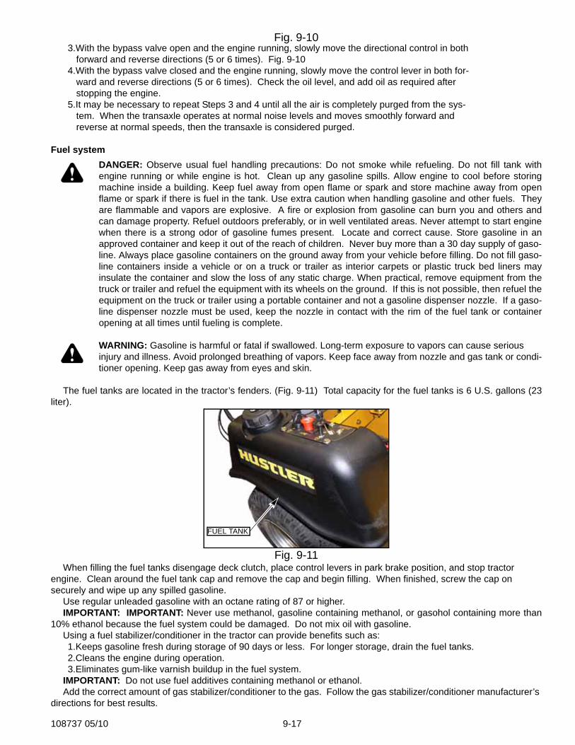
The fuel tanks are located in the tractor’s fenders. (Fig. 9-11) Total capacity for the fuel tanks is 6 U.S. gallons (23liter).
When filling the fuel tanks disengage deck clutch, place control levers in park brake position, and stop tractor engine. Clean around the fuel tank cap and remove the cap and begin filling. When finished, screw the cap on securely and wipe up any spilled gasoline.
Use regular unleaded gasoline with an octane rating of 87 or higher.IMPORTANT: IMPORTANT: Never use methanol, gasoline containing methanol, or gasohol containing more than
10% ethanol because the fuel system could be damaged. Do not mix oil with gasoline.Using a fuel stabilizer/conditioner in the tractor can provide benefits such as:1.Keeps gasoline fresh during storage of 90 days or less. For longer storage, drain the fuel tanks.2.Cleans the engine during operation.3.Eliminates gum-like varnish buildup in the fuel system.
IMPORTANT: Do not use fuel additives containing methanol or ethanol.Add the correct amount of gas stabilizer/conditioner to the gas. Follow the gas stabilizer/conditioner manufacturer’s
directions for best results.
Fig. 9-10
Fig. 9-11
FUEL TANK
9-18 108737 05/10
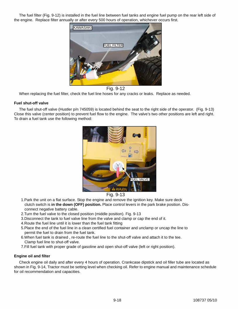
The fuel filter (Fig. 9-12) is installed in the fuel line between fuel tanks and engine fuel pump on the rear left side of the engine. Replace filter annually or after every 500 hours of operation, whichever occurs first.
When replacing the fuel filter, check the fuel line hoses for any cracks or leaks. Replace as needed.
Fuel shut-off valveThe fuel shut-off valve (Hustler p/n 745059) is located behind the seat to the right side of the operator. (Fig. 9-13)
Close this valve (center position) to prevent fuel flow to the engine. The valve’s two other positions are left and right. To drain a fuel tank use the following method:
1.Park the unit on a flat surface. Stop the engine and remove the ignition key. Make sure deck clutch switch is in the down (OFF) position. Place control levers in the park brake position. Dis-connect negative battery cable.
2.Turn the fuel valve to the closed position (middle position). Fig. 9-133.Disconnect the tank to fuel valve line from the valve and clamp or cap the end of it. 4.Route the fuel line until it is lower than the fuel tank fitting 5.Place the end of the fuel line in a clean certified fuel container and unclamp or uncap the line to
permit the fuel to drain from the fuel tank.6.When fuel tank is drained , re-route the fuel line to the shut-off valve and attach it to the tee.
Clamp fuel line to shut-off valve.7.Fill fuel tank with proper grade of gasoline and open shut-off valve (left or right position).
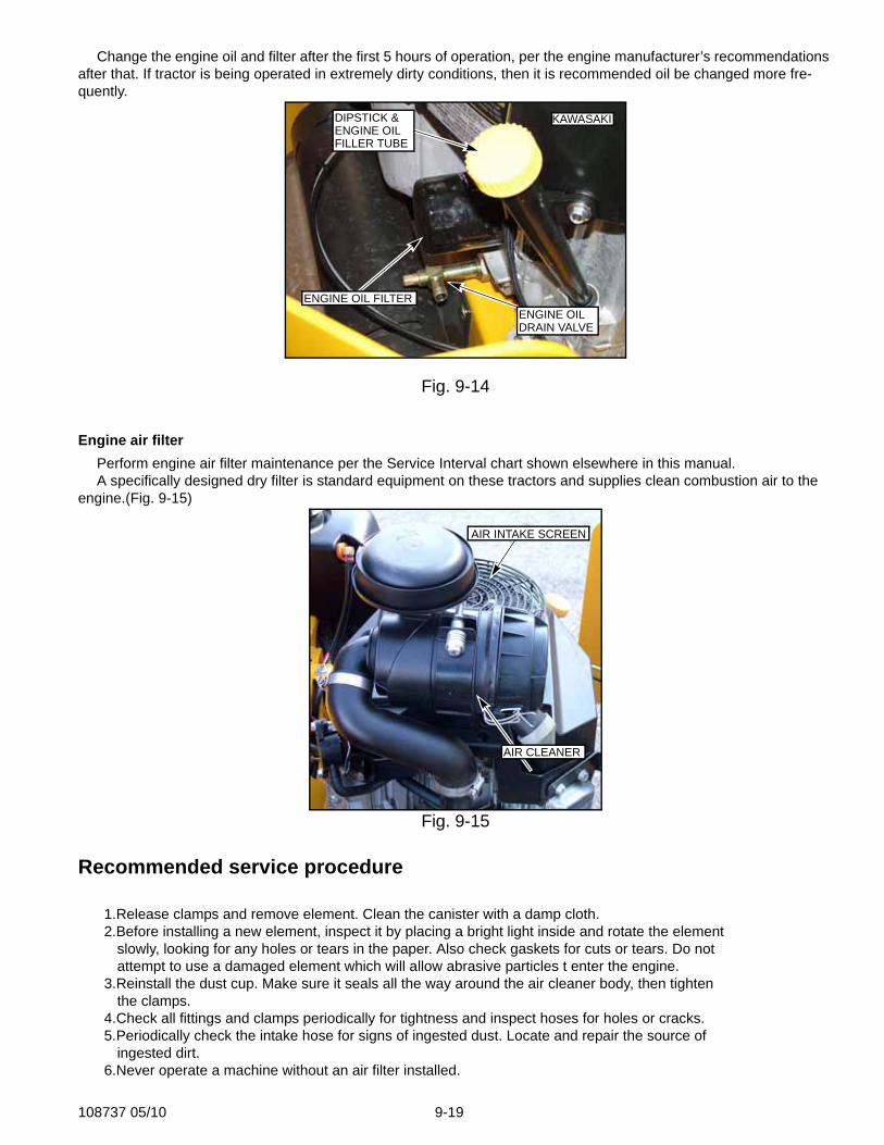
Engine oil and filterCheck engine oil daily and after every 4 hours of operation. Crankcase dipstick and oil filler tube are located as
shown in Fig. 9-14, Tractor must be setting level when checking oil. Refer to engine manual and maintenance schedule for oil recommendation and capacities.
Fig. 9-12
Fig. 9-13
KAWASAKI
FUEL FILTER
FUEL VALVE
108737 05/10 9-19
Change the engine oil and filter after the first 5 hours of operation, per the engine manufacturer’s recommendations after that. If tractor is being operated in extremely dirty conditions, then it is recommended oil be changed more fre-quently.
Engine air filterPerform engine air filter maintenance per the Service Interval chart shown elsewhere in this manual.A specifically designed dry filter is standard equipment on these tractors and supplies clean combustion air to the
engine.(Fig. 9-15)
Recommended service procedure
1.Release clamps and remove element. Clean the canister with a damp cloth.2.Before installing a new element, inspect it by placing a bright light inside and rotate the element
slowly, looking for any holes or tears in the paper. Also check gaskets for cuts or tears. Do not attempt to use a damaged element which will allow abrasive particles t enter the engine.
3.Reinstall the dust cup. Make sure it seals all the way around the air cleaner body, then tighten the clamps.
4.Check all fittings and clamps periodically for tightness and inspect hoses for holes or cracks.5.Periodically check the intake hose for signs of ingested dust. Locate and repair the source of
ingested dirt.6.Never operate a machine without an air filter installed.
Fig. 9-14
Fig. 9-15
ENGINE OIL FILTER
DIPSTICK &ENGINE OILFILLER TUBE
ENGINE OILDRAIN VALVE
KAWASAKI
AIR CLEANER
AIR INTAKE SCREEN
9-20 108737 05/10
Overservicing
Overservicing occurs when an air filter element is removed for cleaning or replacement before it is necessary. Each time the filter is removed, a small amount of dirt and dust could fall in the intake system. This accumulated dirt can cause a dusted engine.
Do not clean element, replace with a new element only. Cleaning used air filter elements, through improper cleaning procedures, can get dust on the inside of the filter causing dirt ingestion and engine failure.
It is important to note that whenever an air filter element is cleaned by any method, the person or company per-forming the cleaning assumes responsibility for the integrity of the filter from then on. The warranty for air filter expires upon cleaning or servicing in any manner because the condition of the filter after servicing is com-pletely out of their control. Therefore, on a dust ingested engine failure, there will be no warranty consider-ation if the air filter element has been cleaned or serviced in any manner.
A partially dirty air filter element works better than a new element. Therefore, a dirty filter element is not bad for the engine unless it is excessively restricting the are flow and engine performance is affected. The reason: the media in the in the filter must be porous t allow air to pass through it. When dirty air passes through the filter, the dirt plugs some of the holes in the media and actually acts as part of the filter media. When the next round of dirt enters, the first dirt helps filter out even smaller particles making the filter more efficient at stopping dirt from entering the engine. This is referred to as barrier filtration.
Of course, at some point the filter media becomes too clogged to allow air to pass and the filter element must be replaced.
The mowing conditions will determine the frequency of air filter element changing.
General engine maintenanceDetailed instructions and recommendations for break-in and regular maintenance are specified in the Engine
Owner’s manual. Please refer to this manual for engine servicing, lubricating oil levels with quality and viscosity recom-mendations, bolt torques, etc. The engine warranty is backed by the manufacturer. Special attention should be paid to applicable data which will not be duplicated here.
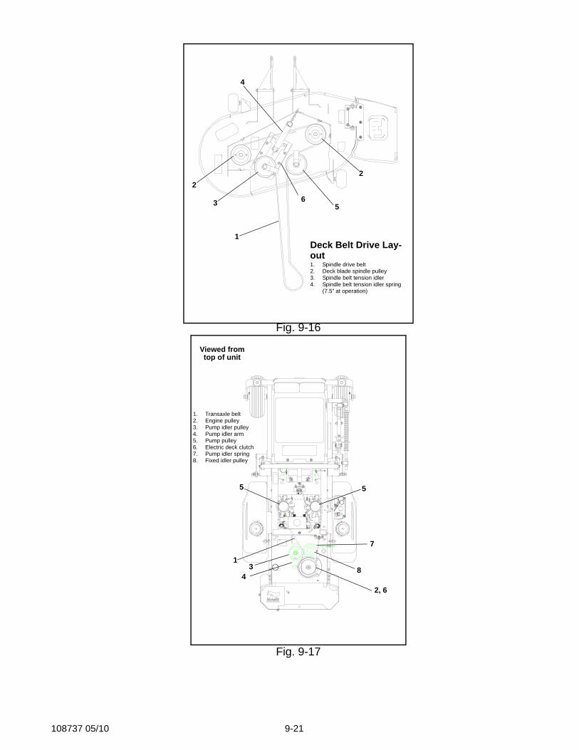
Drive belt replacementFig. 9-16 and Fig. 9-17 show diagrams and descriptions of the unit’s belt drive systems.Inspect these belts frequently for wear and serviceability. Replace a belt that shows signs of severe cuts, tears, sep-
aration, weather checking and cracking, or burns caused by slipping. Slight raveling of belt covering does not indicate failure, trim ravellings with a sharp knife.
WARNING: If the pump belt fails, loss of control will occur especially when operating on a slope. If you lose steering control while operating the machine, place the steering control levers in the park brake position immediately. Inspect the machine and involve your Hustler dealer to resolve the
problem before continuing to operate.
Inspect the belt pulley grooves and flanges for wear. A new belt, or one in good condition, should never run against the bottom of the groove. Replace the pulley when this is the case, otherwise belt will lose power and slip excessively. Never pry a belt to get it on a pulley as this will cut or damage the fibers of the belt covering. Keep oil and grease away from belts, and never use belt dressings. Any of these will destroy the belt composition in a very short time.
108737 05/10 9-21
Fig. 9-16
Fig. 9-17
2
1
2
4
563
Deck Belt Drive Lay-out 1. Spindle drive belt2. Deck blade spindle pulley3. Spindle belt tension idler4. Spindle belt tension idler spring
(7.5” at operation)
1. Transaxle belt2. Engine pulley3. Pump idler pulley4. Pump idler arm5. Pump pulley6. Electric deck clutch7. Pump idler spring8. Fixed idler pulley
1
2, 6
34
5
7
5
8
Viewed fromtop of unit
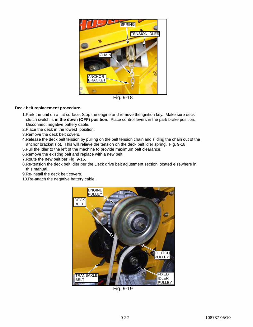
9-22 108737 05/10
Deck belt replacement procedure1.Park the unit on a flat surface. Stop the engine and remove the ignition key. Make sure deck
clutch switch is in the down (OFF) position. Place control levers in the park brake position. Disconnect negative battery cable.
2.Place the deck in the lowest position.3.Remove the deck belt covers.4.Release the deck belt tension by pulling on the belt tension chain and sliding the chain out of the
anchor bracket slot. This will relieve the tension on the deck belt idler spring. Fig. 9-185.Pull the idler to the left of the machine to provide maximum belt clearance.6.Remove the existing belt and replace with a new belt.7.Route the new belt per Fig. 9-16.8.Re-tension the deck belt idler per the Deck drive belt adjustment section located elsewhere in
this manual.9.Re-install the deck belt covers.10.Re-attach the negative battery cable.
Fig. 9-18
Fig. 9-19
ANCHORBRACKET
SPRING
TENSION IDLER
CHAIN
ENGINEPULLEY
CLUTCHPULLEY
TRANSAXLEBELT
DECKBELT
FIXEDIDLERPULLEY
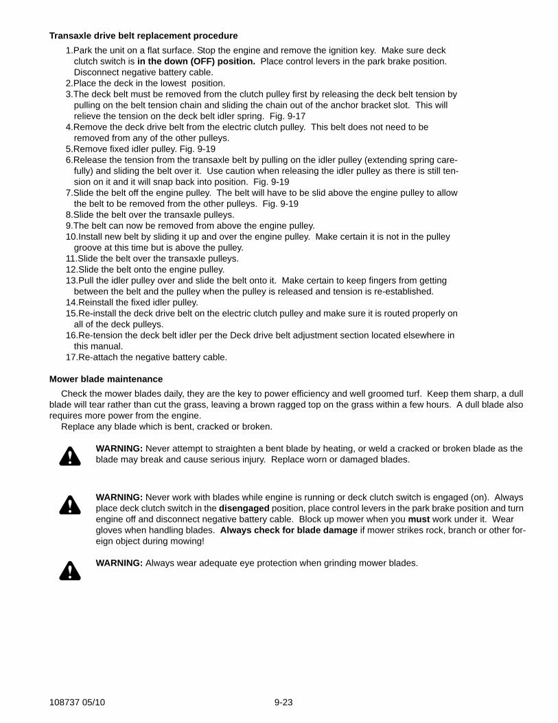
108737 05/10 9-23
Transaxle drive belt replacement procedure1.Park the unit on a flat surface. Stop the engine and remove the ignition key. Make sure deck
clutch switch is in the down (OFF) position. Place control levers in the park brake position. Disconnect negative battery cable.
2.Place the deck in the lowest position.3.The deck belt must be removed from the clutch pulley first by releasing the deck belt tension by
pulling on the belt tension chain and sliding the chain out of the anchor bracket slot. This will relieve the tension on the deck belt idler spring. Fig. 9-17
4.Remove the deck drive belt from the electric clutch pulley. This belt does not need to be removed from any of the other pulleys.
5.Remove fixed idler pulley. Fig. 9-196.Release the tension from the transaxle belt by pulling on the idler pulley (extending spring care-
fully) and sliding the belt over it. Use caution when releasing the idler pulley as there is still ten-sion on it and it will snap back into position. Fig. 9-19
7.Slide the belt off the engine pulley. The belt will have to be slid above the engine pulley to allow the belt to be removed from the other pulleys. Fig. 9-19
8.Slide the belt over the transaxle pulleys.9.The belt can now be removed from above the engine pulley.10.Install new belt by sliding it up and over the engine pulley. Make certain it is not in the pulley
groove at this time but is above the pulley.11.Slide the belt over the transaxle pulleys.12.Slide the belt onto the engine pulley.13.Pull the idler pulley over and slide the belt onto it. Make certain to keep fingers from getting
between the belt and the pulley when the pulley is released and tension is re-established.14.Reinstall the fixed idler pulley.15.Re-install the deck drive belt on the electric clutch pulley and make sure it is routed properly on
all of the deck pulleys.16.Re-tension the deck belt idler per the Deck drive belt adjustment section located elsewhere in
this manual.17.Re-attach the negative battery cable.
Mower blade maintenanceCheck the mower blades daily, they are the key to power efficiency and well groomed turf. Keep them sharp, a dull
blade will tear rather than cut the grass, leaving a brown ragged top on the grass within a few hours. A dull blade also requires more power from the engine.
Replace any blade which is bent, cracked or broken.
WARNING: Never attempt to straighten a bent blade by heating, or weld a cracked or broken blade as the blade may break and cause serious injury. Replace worn or damaged blades.
WARNING: Never work with blades while engine is running or deck clutch switch is engaged (on). Always place deck clutch switch in the disengaged position, place control levers in the park brake position and turn engine off and disconnect negative battery cable. Block up mower when you must work under it. Wear gloves when handling blades. Always check for blade damage if mower strikes rock, branch or other for-eign object during mowing!
WARNING: Always wear adequate eye protection when grinding mower blades.
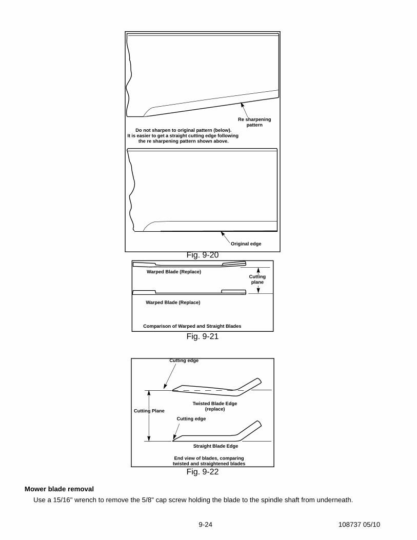
9-24 108737 05/10
Mower blade removalUse a 15/16" wrench to remove the 5/8" cap screw holding the blade to the spindle shaft from underneath.
Fig. 9-20
Fig. 9-21
Fig. 9-22
Re sharpening pattern
Do not sharpen to original pattern (below).It is easier to get a straight cutting edge following
the re sharpening pattern shown above.
Original edge
Warped Blade (Replace)
Warped Blade (Replace)
Comparison of Warped and Straight Blades
Cutting plane
Cutting edge
Cutting edge
Twisted Blade Edge (replace)
Straight Blade Edge
End view of blades, comparingtwisted and straightened blades
Cutting Plane
108737 05/10 9-25
Blade Lock Tool, part number 381442, is available from your dealer to prevent the blades from turning while remov-ing or and installing the blade bolts.
Sharpen the blades on a grinder following pattern as shown (Fig. 9-20). Touch-up sharpening can be done with a file.
Check the blades for balance following grinding. A commercial balancing tool is available through most hardware supply stores, or balancing can be done by placing the blade on an inverted line punch or 5/8" bolt. Blade should not lean or tilt. Spin the blade slowly, blade should not wobble. If blade is out of balance, true it up before reinstalling.
Lay the blade on a flat surface and check for distortion (Fig. 9-21 and Fig. 9-22). Replace any distorted blade.Do not re-use spindle bolts which have stripped, worn or undercut threads. Torque bolts on spindles to 118 foot-
pounds when reinstalling blades. IMPORTANT: The blade sail (curved part) must be pointing upward toward the inside of the deck to ensure proper
cutting.
WARNING: When mounting blades, rotate them after installation to ensure blade tips do not touch each other or sides of the mower.
WARNING: Failure to correctly torque the bolt may result in the loss of the blade which can cause serious injury.
WARNING: Mower blades are sharp and can cut. Wrap the blade(s) or wear gloves and use extra caution when servicing them.
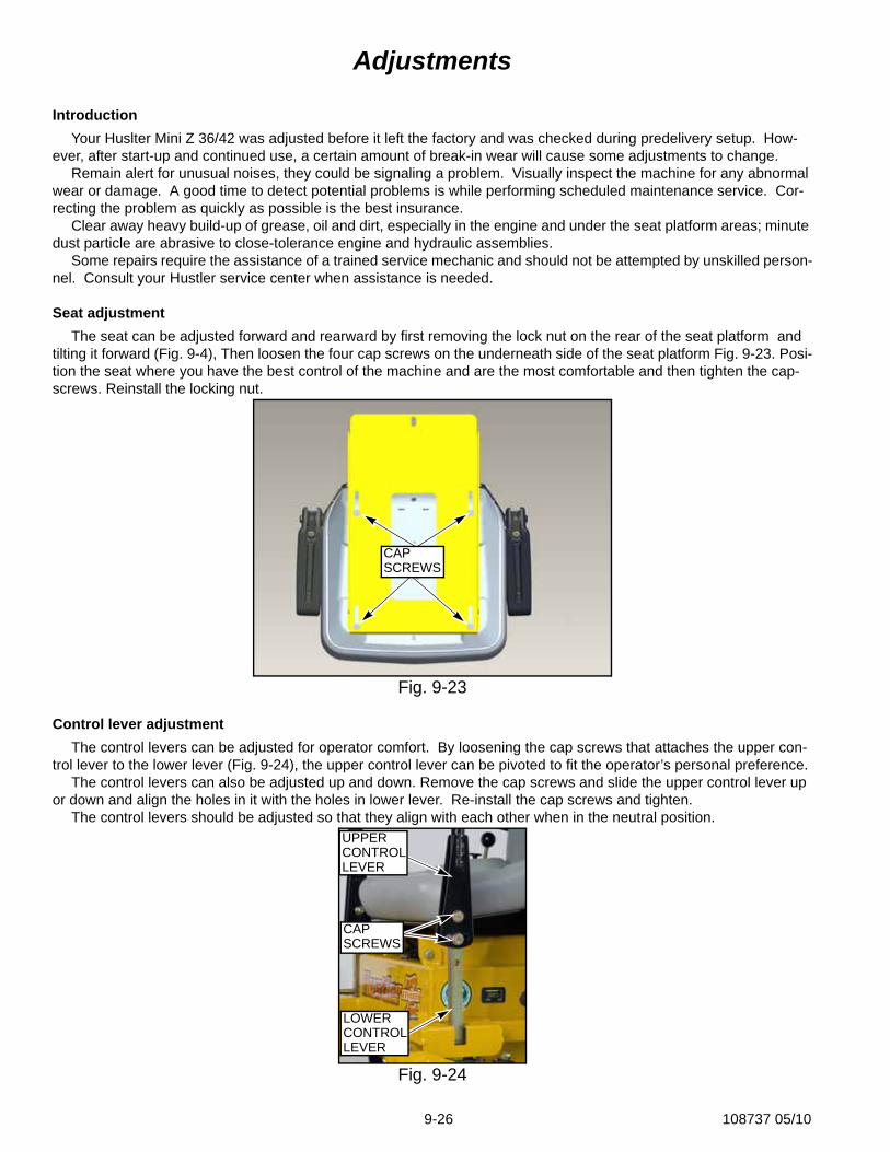
9-26 108737 05/10
Adjustments
IntroductionYour Huslter Mini Z 36/42 was adjusted before it left the factory and was checked during predelivery setup. How-
ever, after start-up and continued use, a certain amount of break-in wear will cause some adjustments to change.Remain alert for unusual noises, they could be signaling a problem. Visually inspect the machine for any abnormal
wear or damage. A good time to detect potential problems is while performing scheduled maintenance service. Cor-recting the problem as quickly as possible is the best insurance.
Clear away heavy build-up of grease, oil and dirt, especially in the engine and under the seat platform areas; minute dust particle are abrasive to close-tolerance engine and hydraulic assemblies.
Some repairs require the assistance of a trained service mechanic and should not be attempted by unskilled person-nel. Consult your Hustler service center when assistance is needed.
Seat adjustmentThe seat can be adjusted forward and rearward by first removing the lock nut on the rear of the seat platform and
tilting it forward (Fig. 9-4), Then loosen the four cap screws on the underneath side of the seat platform Fig. 9-23. Posi-tion the seat where you have the best control of the machine and are the most comfortable and then tighten the cap-screws. Reinstall the locking nut.
Control lever adjustmentThe control levers can be adjusted for operator comfort. By loosening the cap screws that attaches the upper con-
trol lever to the lower lever (Fig. 9-24), the upper control lever can be pivoted to fit the operator’s personal preference.The control levers can also be adjusted up and down. Remove the cap screws and slide the upper control lever up
or down and align the holes in it with the holes in lower lever. Re-install the cap screws and tighten.The control levers should be adjusted so that they align with each other when in the neutral position.
Fig. 9-23
Fig. 9-24
CAPSCREWS
UPPERCONTROLLEVER
CAPSCREWS
LOWERCONTROLLEVER
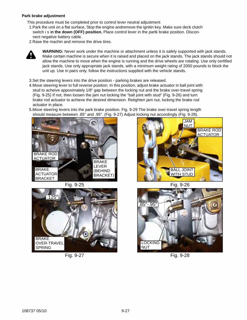
108737 05/10 9-27
Park brake adjustmentThis procedure must be completed prior to control lever neutral adjustment1.Park the unit on a flat surface, Stop the engine andremove the ignitin key. Make sure deck clutch
switch i s in the down (OFF) position. Place control lever in the partk brake position. Discon-nect negative battery cable.
2.Rase the machin and remove the drive tires.
WARNING: Never work under the machine or attachment unless it is safely supported with jack stands. Make certain machine is secure when it is raised and placed on the jack stands. The jack stands should not allow the machine to move when the engine is running and the drive wheels are rotating. Use only certified jack stands. Use only appropriate jack stands, with a minimum weight rating of 2000 pounds to block the unit up. Use in pairs only. follow the instructions supplied with the vehicle stands.
3.Set the steering levers into the drive position - parking brakes are released.4.Move steering lever to full reverse position. In this position, adjust brake actuator in ball joint with
stud to acheive appoximately 1/8” gap between the locking nut and the brake over-travel spring (Fig. 9-25) If not, then loosen the jam nut locking the “ball joint with stud” (Fig. 9-26) and turn brake rod actuator to achieve the desired dimension. Retighten jam nut, locking the brake rod actuator in place.
5.Move steering levers into the park brake position. Fig. 9-29 The brake over-travel spring length should measure between .85" and .95". (Fig. 9-27) Adjust locking nut accordingly (Fig. 9-28).
Fig. 9-25 Fig. 9-26
Fig. 9-27 Fig. 9-28
BRAKEACTUATORBRACKET
BRAKE RODACTUATOR
BRAKELEVER(BEHINDBRACKET)
BRAKE RODACTUATOR
BALL JOINTWITH STUD
JAMNUT
BRAKEOVER-TRAVELSPRING
.125"
LOCKINGNUT
.85"-.95"
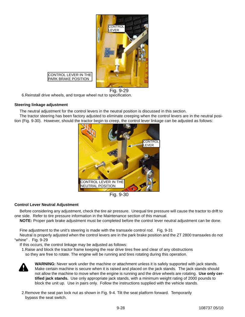
9-28 108737 05/10
6.Reinstall drive wheels, and torque wheel nut to specification.
Steering linkage adjustmentThe neutral adjustment for the control levers in the neutral position is discussed in this section.The tractor steering has been factory adjusted to eliminate creeping when the control levers are in the neutral posi-
tion (Fig. 9-30). However, should the tractor begin to creep, the control lever linkage can be adjusted as follows:
Control Lever Neutral AdjustmentBefore considering any adjustment, check the tire air pressure. Unequal tire pressure will cause the tractor to drift to
one side. Refer to tire pressure information in the Maintenance section of this manual.NOTE: Proper park brake adjustment must be completed before the control lever neutral adjustment can be done.
Fine adjustment to the unit’s steering is made with the transaxle control rod. Fig. 9-31Neutral is properly adjusted when the control levers are in the park brake position and the ZT 2800 transaxles do not
“whine” . Fig. 9-29If this occurs, the control linkage may be adjusted as follows:1.Raise and block the tractor frame keeping the rear drive tires free and clear of any obstructions
so they are free to rotate. The engine will be running and tires rotating during this operation.
WARNING: Never work under the machine or attachment unless it is safely supported with jack stands. Make certain machine is secure when it is raised and placed on the jack stands. The jack stands should not allow the machine to move when the engine is running and the drive wheels are rotating. Use only cer-tified jack stands. Use only appropriate jack stands, with a minimum weight rating of 2000 pounds to block the unit up. Use in pairs only. Follow the instructions supplied with the vehicle stands.
2.Remove the seat pan lock nut as shown in Fig. 9-4. Tilt the seat platform forward. Temporarily bypass the seat switch.
Fig. 9-29
Fig. 9-30
CONTROLLEVER
CONTROL LEVER IN THEPARK BRAKE POSITION
CONTROL LEVER IN THENEUTRAL POSITION
CONTROLLEVERCONTROLLEVER
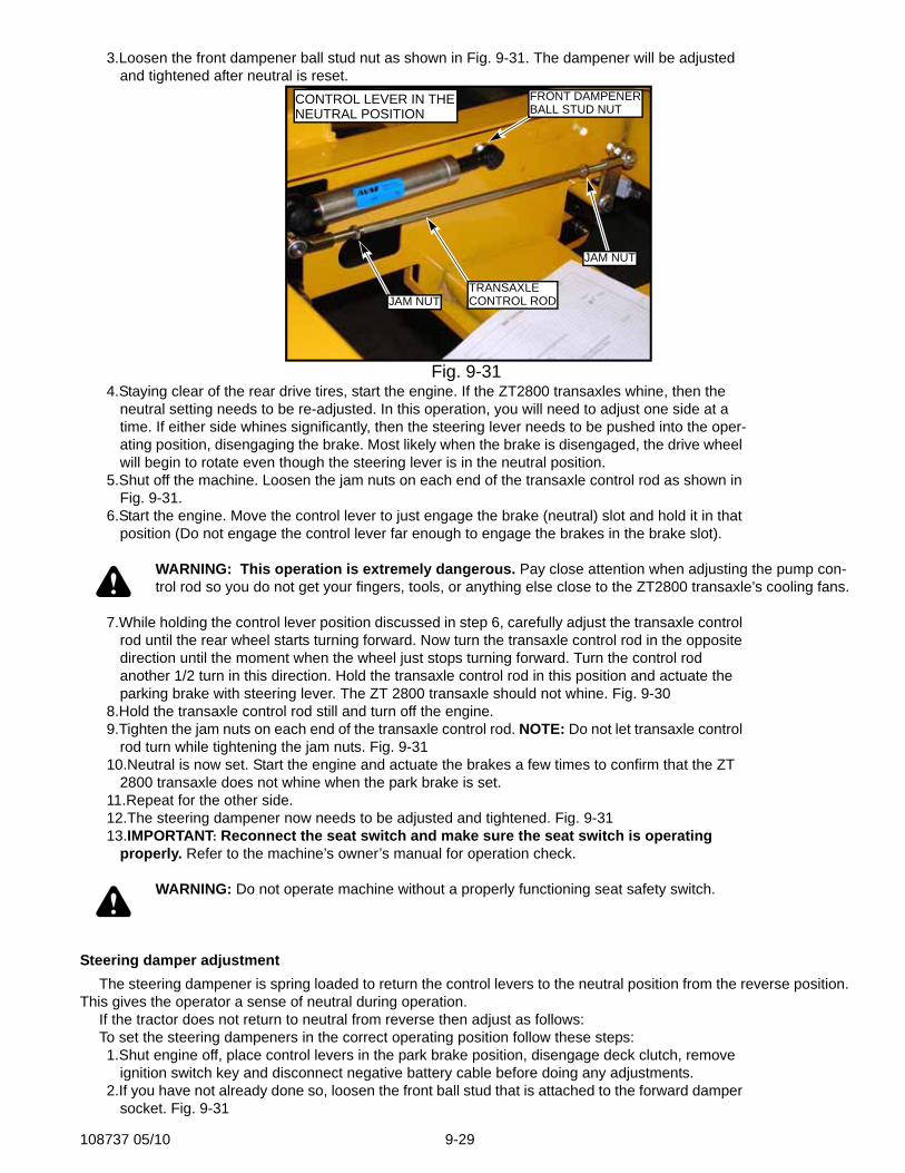
108737 05/10 9-29
3.Loosen the front dampener ball stud nut as shown in Fig. 9-31. The dampener will be adjusted and tightened after neutral is reset.
4.Staying clear of the rear drive tires, start the engine. If the ZT2800 transaxles whine, then the neutral setting needs to be re-adjusted. In this operation, you will need to adjust one side at a time. If either side whines significantly, then the steering lever needs to be pushed into the oper-ating position, disengaging the brake. Most likely when the brake is disengaged, the drive wheel will begin to rotate even though the steering lever is in the neutral position.
5.Shut off the machine. Loosen the jam nuts on each end of the transaxle control rod as shown in Fig. 9-31.
6.Start the engine. Move the control lever to just engage the brake (neutral) slot and hold it in that position (Do not engage the control lever far enough to engage the brakes in the brake slot).
WARNING: This operation is extremely dangerous. Pay close attention when adjusting the pump con-trol rod so you do not get your fingers, tools, or anything else close to the ZT2800 transaxle’s cooling fans.
7.While holding the control lever position discussed in step 6, carefully adjust the transaxle control rod until the rear wheel starts turning forward. Now turn the transaxle control rod in the opposite direction until the moment when the wheel just stops turning forward. Turn the control rod another 1/2 turn in this direction. Hold the transaxle control rod in this position and actuate the parking brake with steering lever. The ZT 2800 transaxle should not whine. Fig. 9-30
8.Hold the transaxle control rod still and turn off the engine.9.Tighten the jam nuts on each end of the transaxle control rod. NOTE: Do not let transaxle control
rod turn while tightening the jam nuts. Fig. 9-3110.Neutral is now set. Start the engine and actuate the brakes a few times to confirm that the ZT
2800 transaxle does not whine when the park brake is set. 11.Repeat for the other side. 12.The steering dampener now needs to be adjusted and tightened. Fig. 9-3113.IMPORTANT: Reconnect the seat switch and make sure the seat switch is operating
properly. Refer to the machine’s owner’s manual for operation check.
WARNING: Do not operate machine without a properly functioning seat safety switch.
Steering damper adjustmentThe steering dampener is spring loaded to return the control levers to the neutral position from the reverse position.
This gives the operator a sense of neutral during operation.If the tractor does not return to neutral from reverse then adjust as follows:To set the steering dampeners in the correct operating position follow these steps:1.Shut engine off, place control levers in the park brake position, disengage deck clutch, remove
ignition switch key and disconnect negative battery cable before doing any adjustments.2.If you have not already done so, loosen the front ball stud that is attached to the forward damper
socket. Fig. 9-31
Fig. 9-31
CONTROL LEVER IN THENEUTRAL POSITION
JAM NUT
TRANSAXLECONTROL RODJAM NUT
FRONT DAMPENERBALL STUD NUT
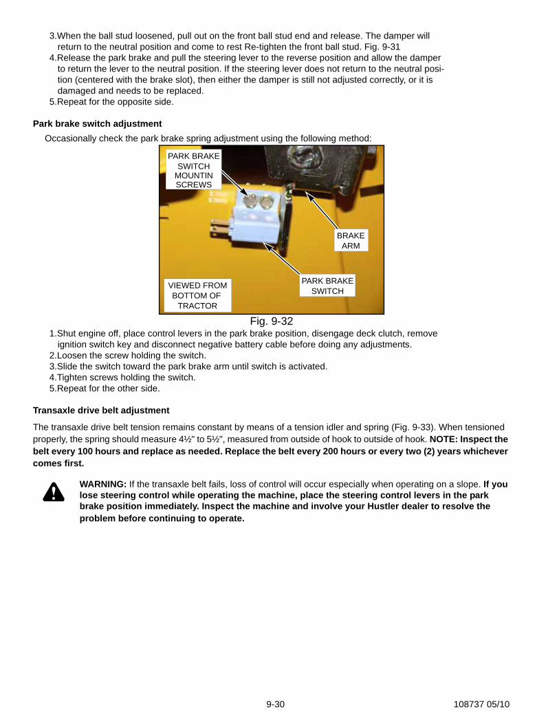
9-30 108737 05/10
3.When the ball stud loosened, pull out on the front ball stud end and release. The damper will return to the neutral position and come to rest Re-tighten the front ball stud. Fig. 9-31
4.Release the park brake and pull the steering lever to the reverse position and allow the damper to return the lever to the neutral position. If the steering lever does not return to the neutral posi-tion (centered with the brake slot), then either the damper is still not adjusted correctly, or it is damaged and needs to be replaced.
5.Repeat for the opposite side.
Park brake switch adjustmentOccasionally check the park brake spring adjustment using the following method:
1.Shut engine off, place control levers in the park brake position, disengage deck clutch, remove ignition switch key and disconnect negative battery cable before doing any adjustments.
2.Loosen the screw holding the switch.3.Slide the switch toward the park brake arm until switch is activated.4.Tighten screws holding the switch.5.Repeat for the other side.
Transaxle drive belt adjustment
The transaxle drive belt tension remains constant by means of a tension idler and spring (Fig. 9-33). When tensioned properly, the spring should measure 4½" to 5½", measured from outside of hook to outside of hook. NOTE: Inspect the belt every 100 hours and replace as needed. Replace the belt every 200 hours or every two (2) years whichever comes first.
WARNING: If the transaxle belt fails, loss of control will occur especially when operating on a slope. If you lose steering control while operating the machine, place the steering control levers in the park brake position immediately. Inspect the machine and involve your Hustler dealer to resolve the problem before continuing to operate.
Fig. 9-32
VIEWED FROMBOTTOM OF
TRACTOR
PARK BRAKESWITCH
PARK BRAKESWITCH
MOUNTINSCREWS
BRAKEARM
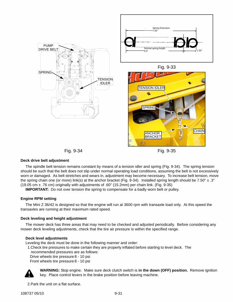
108737 05/10 9-31
Deck drive belt adjustmentThe spindle belt tension remains constant by means of a tension idler and spring (Fig. 9-34). The spring tension
should be such that the belt does not slip under normal operating load conditions, assuming the belt is not excessively worn or damaged. As belt stretches and wears in, adjustment may become necessary. To increase belt tension, move the spring chain one (or more) link(s) at the anchor bracket (Fig. 9-34). Installed spring length should be 7.50" ± .3" (19.05 cm ± .76 cm) originally with adjustments of .60" (15.2mm) per chain link. (Fig. 9-35)
IMPORTANT: Do not over tension the spring to compensate for a badly worn belt or pulley.
Engine RPM settingThe Mini Z 36/42 is designed so that the engine will run at 3600 rpm with transaxle load only. At this speed the
transaxles are running at their maximum rated speed.
Deck leveling and height adjustmentThe mower deck has three areas that may need to be checked and adjusted periodically. Before considering any
mower deck leveling adjustments, check that the tire air pressure is within the specified range.
Deck level adjustmentsLeveling the deck must be done in the following manner and order:1.Check tire pressures to make certain they are properly inflated before starting to level deck. The
recommended pressures are as follows: Drive wheels tire pressure 8 - 10 psi Front wheels tire pressure 8 - 10 psi
WARNING: Stop engine. Make sure deck clutch switch is in the down (OFF) position. Remove ignition key. Place control levers in the brake position before leaving machine.
2.Park the unit on a flat surface.
Fig. 9-33
Fig. 9-34 Fig. 9-35
TENSIONIDLER
SPRING
PUMPDRIVE BELT
Spring Extension7.50”
Normal spring length6.0” 1.50”
CHAINANCHORBRACKET
SPRING
TENSION IDLER
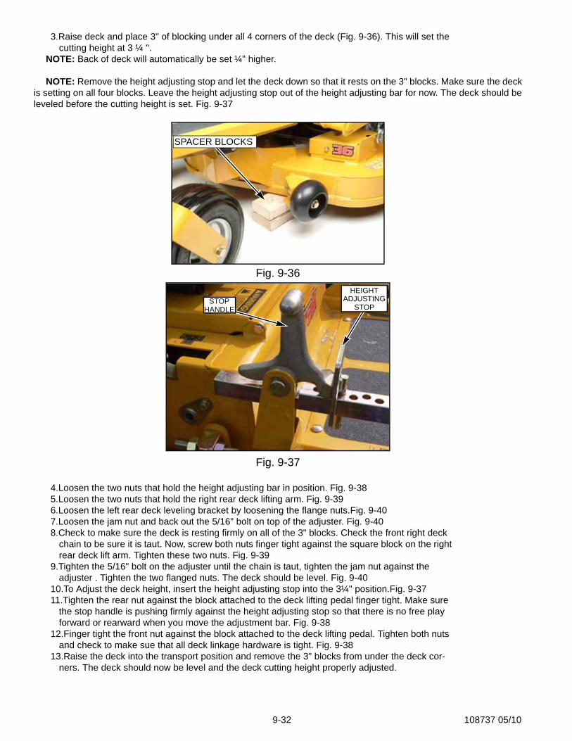
9-32 108737 05/10
3.Raise deck and place 3" of blocking under all 4 corners of the deck (Fig. 9-36). This will set the cutting height at 3 ¼ ".
NOTE: Back of deck will automatically be set ¼" higher.
NOTE: Remove the height adjusting stop and let the deck down so that it rests on the 3" blocks. Make sure the deckis setting on all four blocks. Leave the height adjusting stop out of the height adjusting bar for now. The deck should beleveled before the cutting height is set. Fig. 9-37
4.Loosen the two nuts that hold the height adjusting bar in position. Fig. 9-385.Loosen the two nuts that hold the right rear deck lifting arm. Fig. 9-396.Loosen the left rear deck leveling bracket by loosening the flange nuts.Fig. 9-407.Loosen the jam nut and back out the 5/16" bolt on top of the adjuster. Fig. 9-408.Check to make sure the deck is resting firmly on all of the 3" blocks. Check the front right deck
chain to be sure it is taut. Now, screw both nuts finger tight against the square block on the right rear deck lift arm. Tighten these two nuts. Fig. 9-39
9.Tighten the 5/16" bolt on the adjuster until the chain is taut, tighten the jam nut against the adjuster . Tighten the two flanged nuts. The deck should be level. Fig. 9-40
10.To Adjust the deck height, insert the height adjusting stop into the 3¼" position.Fig. 9-3711.Tighten the rear nut against the block attached to the deck lifting pedal finger tight. Make sure
the stop handle is pushing firmly against the height adjusting stop so that there is no free play forward or rearward when you move the adjustment bar. Fig. 9-38
12.Finger tight the front nut against the block attached to the deck lifting pedal. Tighten both nuts and check to make sue that all deck linkage hardware is tight. Fig. 9-38
13.Raise the deck into the transport position and remove the 3" blocks from under the deck cor-ners. The deck should now be level and the deck cutting height properly adjusted.
Fig. 9-36
Fig. 9-37
SPACER BLOCKS
STOPHEIGHT
HANDLEADJUSTING
STOP
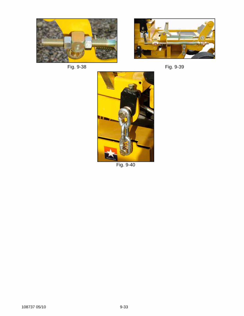
108737 05/10 9-33
Fig. 9-38 Fig. 9-39
Fig. 9-40

9-34 108737 05/10

108737 05/10 i-1
Numerical IndexPart PageNo. No.
Part PageNo. No.
Part PageNo. No.
IndexPart Numbers000323 4-7000331 4-7005108 3-11005116 6-7, 6-13005355 4-3008979 4-3015495 3-5015511 5-3015818 4-7016816 4-3017004 4-3017616 7-2019521 5-3, 5-4023655 3-11024927 3-3, 3-11025007 3-7, 6-7, 6-13025296 3-5, 3-7, 5-2025395 2-4026237 4-9028118 3-7, 6-7, 6-13029868 3-3029876 3-11, 4-3030817 3-3031997 2-3, 6-3, 6-5, 6-9,
6-11034272 3-5, 3-7, 3-11, 4-3,
6-3, 6-5, 6-9, 6-11034280 4-3, 6-3, 6-5, 6-7,
6-9, 6-11, 6-13, 7-4036244 7-4036384 3-7043570 4-7044255 3-3045765 5-2045898 4-9048553 3-11050161 4-3052860 2-4, 4-3, 7-4053199 2-3, 6-3, 6-5, 6-9,
6-11054502 2-4, 3-7, 3-11, 6-3,
6-7, 6-9, 6-13055749 3-5, 7-2055822 4-7055939 3-3, 3-7, 3-11055947 4-9058776 6-3, 6-7, 6-9, 6-13058842 3-11059832 3-11, 4-9061077 5-4061101 3-7, 5-2
061572 3-11063198 3-11063297 6-3, 6-9064006 6-13068478 1-1068551 3-11079186 3-11083279 8-3086660 2-4, 3-11, 6-5, 6-11,
7-4100867 6-7100875 6-7, 6-13105031 6-7, 6-13105155 6-13105296 6-9, 6-11107011 2-4107300 2-2107318 2-2107608 4-3107630 7-4107631 3-3107633 3-7107637 2-4107644 3-7107654 1-1107696 1-1107708 1-1107794 6-3108071 4-3108467 3-11108468 3-11108588 3-11108598 3-11112877 6-5, 6-11263517 5-2315572 6-5321059 4-9322974 6-3, 6-5, 6-9, 6-11324046 3-7325464 3-11330225 6-5330274 4-3334045 3-5344267 2-3, 5-2347443 6-7, 6-13348284 3-5348318 3-5348458 3-5352724 6-3353961 1-1357103 6-9360131 3-5
360487 3-11364315 3-7, 6-7, 6-13366625 5-2546937 6-5547844 6-9, 6-11547851 2-2547863 6-3547869 2-2600221 3-11600668 5-4600676 5-4600684 5-4600692 5-4600700 5-4600718 5-4600726 1-1, 6-7600734 1-1, 6-13600759 3-7600767 3-7600878 3-11600880 3-7600881 3-7600895 3-11600896 3-11600899 8-3600900 6-7600901 6-7, 6-13600902 4-3600903 4-3600904 4-3600906 4-3600907 4-3600941 8-3600965 3-7600970 3-7600972 3-7, 3-11600974 3-7600975 3-7600976 1-1, 3-7600992 2-4601055 3-7601069 6-3, 6-5, 6-9, 6-11601088 3-11601096 4-9601099 8-3601117 6-3, 6-9601162 3-7601196 3-7601197 3-7601200 3-11601201 3-11601211 3-11
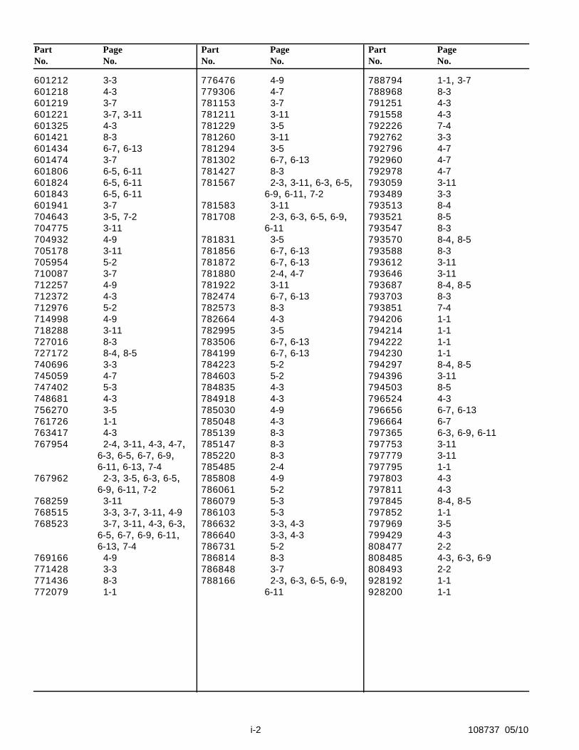
Part PageNo. No.
Part PageNo. No.
Part PageNo. No.
i-2 108737 05/10
601212 3-3601218 4-3601219 3-7601221 3-7, 3-11601325 4-3601421 8-3601434 6-7, 6-13601474 3-7601806 6-5, 6-11601824 6-5, 6-11601843 6-5, 6-11601941 3-7704643 3-5, 7-2704775 3-11704932 4-9705178 3-11705954 5-2710087 3-7712257 4-9712372 4-3712976 5-2714998 4-9718288 3-11727016 8-3727172 8-4, 8-5740696 3-3745059 4-7747402 5-3748681 4-3756270 3-5761726 1-1763417 4-3767954 2-4, 3-11, 4-3, 4-7,
6-3, 6-5, 6-7, 6-9, 6-11, 6-13, 7-4
767962 2-3, 3-5, 6-3, 6-5, 6-9, 6-11, 7-2
768259 3-11768515 3-3, 3-7, 3-11, 4-9768523 3-7, 3-11, 4-3, 6-3,
6-5, 6-7, 6-9, 6-11, 6-13, 7-4
769166 4-9771428 3-3771436 8-3772079 1-1
776476 4-9779306 4-7781153 3-7781211 3-11781229 3-5781260 3-11781294 3-5781302 6-7, 6-13781427 8-3781567 2-3, 3-11, 6-3, 6-5,
6-9, 6-11, 7-2781583 3-11781708 2-3, 6-3, 6-5, 6-9,
6-11781831 3-5781856 6-7, 6-13781872 6-7, 6-13781880 2-4, 4-7781922 3-11782474 6-7, 6-13782573 8-3782664 4-3782995 3-5783506 6-7, 6-13784199 6-7, 6-13784223 5-2784603 5-2784835 4-3784918 4-3785030 4-9785048 4-3785139 8-3785147 8-3785220 8-3785485 2-4785808 4-9786061 5-2786079 5-3786103 5-3786632 3-3, 4-3786640 3-3, 4-3786731 5-2786814 8-3786848 3-7788166 2-3, 6-3, 6-5, 6-9,
6-11
788794 1-1, 3-7788968 8-3791251 4-3791558 4-3792226 7-4792762 3-3792796 4-7792960 4-7792978 4-7793059 3-11793489 3-3793513 8-4793521 8-5793547 8-3793570 8-4, 8-5793588 8-3793612 3-11793646 3-11793687 8-4, 8-5793703 8-3793851 7-4794206 1-1794214 1-1794222 1-1794230 1-1794297 8-4, 8-5794396 3-11794503 8-5796524 4-3796656 6-7, 6-13796664 6-7797365 6-3, 6-9, 6-11797753 3-11797779 3-11797795 1-1797803 4-3797811 4-3797845 8-4, 8-5797852 1-1797969 3-5799429 4-3808477 2-2808485 4-3, 6-3, 6-9808493 2-2928192 1-1928200 1-1