Hurricane formation. Hurricanes Hurricane Formation on.com/hurricane2.htm.
Upload
trannguyetCategory
view
225download
0
AMBA Interface for HurriCANe
For HurriCANe Versions 4.x (not suitable for 5.x)
Version: 1.3 Date: June 2005
Luca StagnaroSpacecraft Control and Data Systems DivisionAutomation and Informatics DepartmentEuropean Space Agency ESTEC KEPLERLAAN 1 - 2201 AZ NOORDWIJK – THE NETHERLANDS TEL. (31) 71 5656565 - FAX (31) 71 5656040

Motivation
This documents describe the AMBA components incorporating the Hurricane CANcontroller such it can be integrated in any silicon were the low speed AMBA interface,APB, is present.The motivation for this work is the decision from the Agency to adopt the AMBA busspecification as the standard for on-chip bus interconnection in particular for the runningdevelopment of the LEON Sparc V8 processor.The AMBA specification as such does not constitute any technical challenge, since it issufficiently simple and well documented. The implementation of the inside registers caninstead be quite complex and for the moment has not been provided. A simple singleregister interface is provided in this first version, with the hope to have more compleximplementation in a second time. The interface though support the time synchronizationand distribution as it will be explained later that is essential for space application.
AMBA interfaces
This document is based on the AMBA 2.0 specification that can be downloaded from theARM web site. The specification will not be repeated here, please refer to the ARMdocument. To use the entity you will need the AMBA package, I have added therefore thedeclarations that are needed to use this IP:
Package Interface
type APB_Slv_In_Type is record PSEL: Std_Ulogic;
PENABLE: Std_Ulogic; PADDR: Std_Logic_Vector(PAMAX-1 downto 0); PWRITE: Std_Ulogic; PWDATA: Std_Logic_Vector(PDMAX-1 downto 0);
end record;
type APB_Slv_Out_Type is record
PRDATA: Std_Logic_Vector(PDMAX-1 downto 0);end record;
Chapter
1Chapter
1
2
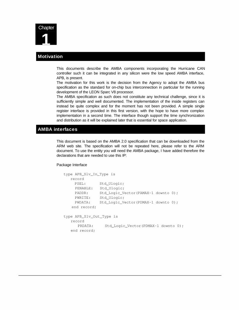
Here is the entity declaration:
Generic ( HURCLK_RATIO : Natural) ;entity HurryAMBA is port( APBIn : in APB_Slv_In_Type; APBOut : out APB_Slv_Out_Type; PresetN : in Std_ULogic; PClock : in Std_ULogic;
-- Non Amba Internal Signals HAIntReq : out Std_ULogic; HASync : out Std_ULogic; HATrig : out Std_ULogic;
-- CAN SignalsCANTX : out std_logic;CANRX : in std_logic);
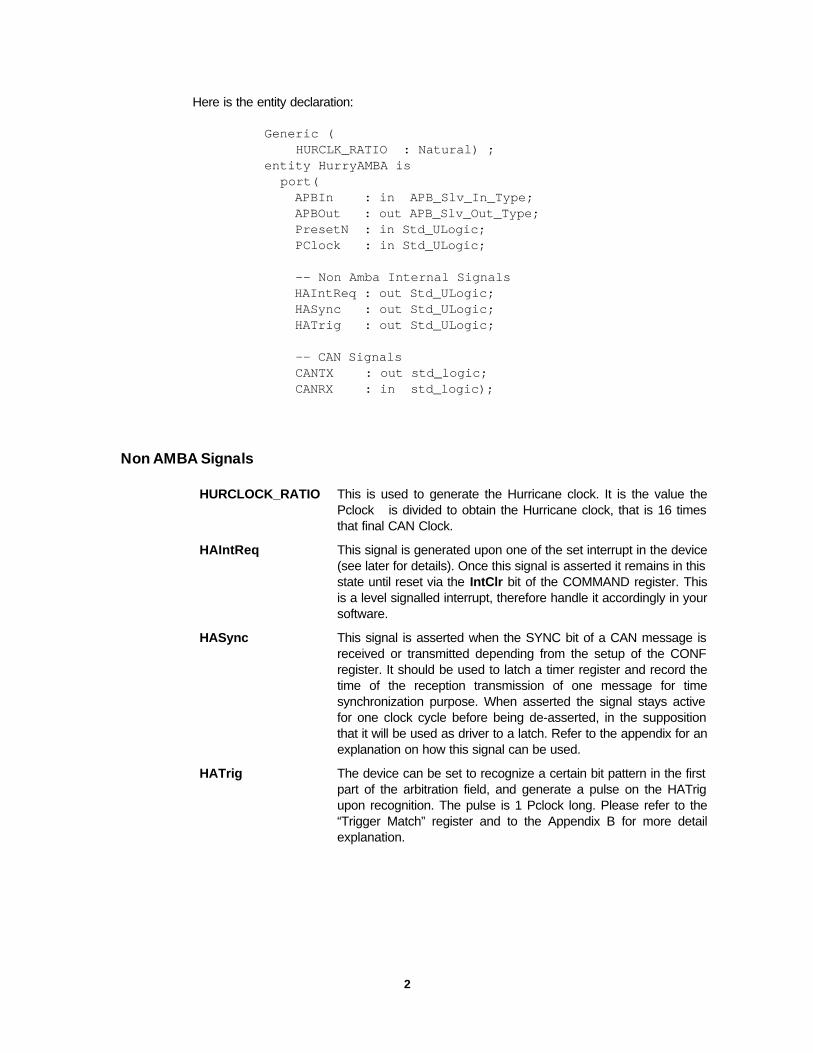
Non AMBA Signals
HURCLOCK_RATIO This is used to generate the Hurricane clock. It is the value thePclock is divided to obtain the Hurricane clock, that is 16 timesthat final CAN Clock.
HAIntReq This signal is generated upon one of the set interrupt in the device(see later for details). Once this signal is asserted it remains in thisstate until reset via the IntClr bit of the COMMAND register. Thisis a level signalled interrupt, therefore handle it accordingly in yoursoftware.
HASync This signal is asserted when the SYNC bit of a CAN message isreceived or transmitted depending from the setup of the CONFregister. It should be used to latch a timer register and record thetime of the reception transmission of one message for timesynchronization purpose. When asserted the signal stays activefor one clock cycle before being de-asserted, in the suppositionthat it will be used as driver to a latch. Refer to the appendix for anexplanation on how this signal can be used.
HATrig The device can be set to recognize a certain bit pattern in the firstpart of the arbitration field, and generate a pulse on the HATrigupon recognition. The pulse is 1 Pclock long. Please refer to the“Trigger Match” register and to the Appendix B for more detailexplanation.
3
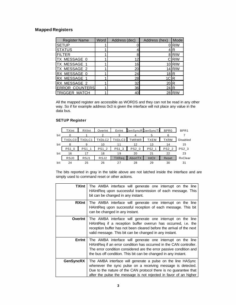
Mapped Registers
Register Name Word Address (dec) Address (hex) ModeSETUP 1 0 0 R/WSTATUS 1 4 4 R FILTER 1 8 8 R/WTX_MESSAGE_0 1 12 C R/WTX_MESSAGE_1 1 16 10 R/WTX_MESSAGE_2 1 20 14 R/WRX_MESSAGE_0 1 24 18 RRX_MESSAGE_1 1 28 1C RRX_MESSAGE_2 1 32 20 RERROR_COUNTERS 1 36 24 RTRIGGER_MATCH 1 40 28 R/W
All the mapped register are accessible as WORDS and they can not be read in any otherway. So if for example address 0x3 is given the interface will not place any value in thedata bus.
SETUP Register
TXInt RXInt OverInt ErrInt GenSyncRXGenSyncTX BPR0 BPR1
bit 0 1 2 3 4 5 6 7
TXDLC0 TXDLC1 TXDLC2 TXDLC3 TMRMR TXEM TXRM Disabled
bit 8 9 10 11 12 13 14 15PS1_0 PS1_1 PS1_2 PS1_3 PS2_0 PS2_1 PS2_2 PS2_3
bit 16 17 18 19 20 21 22 23
RSJ0 RSJ1 RSJ2 TXReq AbortTX IntClr Reset RxClear
bit 24 25 26 27 28 29 30 31
The bits reported in gray in the table above are not latched inside the interface and aresimply used to command reset or other actions.
TXInt The AMBA interface will generate one interrupt on the lineHAIntReq upon successful transmission of each message. Thisbit can be changed in any instant.
RXInt The AMBA interface will generate one interrupt on the lineHAIntReq upon successful reception of each message. This bitcan be changed in any instant.
OverInt The AMBA interface will generate one interrupt on the lineHAIntReq if a reception buffer overrun has occurred, i.e. thereception buffer has not been cleared before the arrival of the nextvalid message. This bit can be changed in any instant.
ErrInt The AMBA interface will generate one interrupt on the lineHAIntReq if an error condition has occurred in the CAN controller.The error condition considered are the error passive condition andthe bus off condition. This bit can be changed in any instant.
GenSyncRX The AMBA interface will generate a pulse on the line HASyncwhenever the sync pulse on a receiving message is detected.Due to the nature of the CAN protocol there is no guarantee thatafter the pulse the message is not rejected in favor of an higher
4
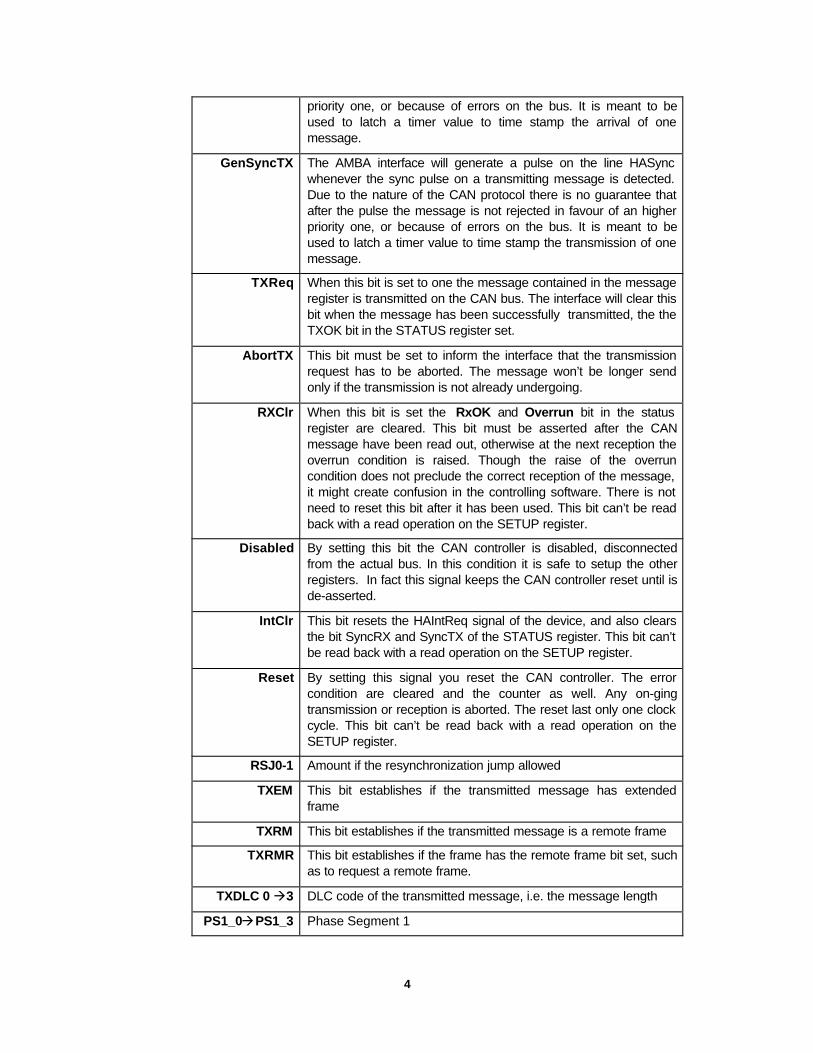
priority one, or because of errors on the bus. It is meant to beused to latch a timer value to time stamp the arrival of onemessage.
GenSyncTX The AMBA interface will generate a pulse on the line HASyncwhenever the sync pulse on a transmitting message is detected.Due to the nature of the CAN protocol there is no guarantee thatafter the pulse the message is not rejected in favour of an higherpriority one, or because of errors on the bus. It is meant to beused to latch a timer value to time stamp the transmission of onemessage.
TXReq When this bit is set to one the message contained in the messageregister is transmitted on the CAN bus. The interface will clear thisbit when the message has been successfully transmitted, the theTXOK bit in the STATUS register set.
AbortTX This bit must be set to inform the interface that the transmissionrequest has to be aborted. The message won’t be longer sendonly if the transmission is not already undergoing.
RXClr When this bit is set the RxOK and Overrun bit in the statusregister are cleared. This bit must be asserted after the CANmessage have been read out, otherwise at the next reception theoverrun condition is raised. Though the raise of the overruncondition does not preclude the correct reception of the message,it might create confusion in the controlling software. There is notneed to reset this bit after it has been used. This bit can’t be readback with a read operation on the SETUP register.
Disabled By setting this bit the CAN controller is disabled, disconnectedfrom the actual bus. In this condition it is safe to setup the otherregisters. In fact this signal keeps the CAN controller reset until isde-asserted.
IntClr This bit resets the HAIntReq signal of the device, and also clearsthe bit SyncRX and SyncTX of the STATUS register. This bit can’tbe read back with a read operation on the SETUP register.
Reset By setting this signal you reset the CAN controller. The errorcondition are cleared and the counter as well. Any on-gingtransmission or reception is aborted. The reset last only one clockcycle. This bit can’t be read back with a read operation on theSETUP register.
RSJ0-1 Amount if the resynchronization jump allowed
TXEM This bit establishes if the transmitted message has extendedframe
TXRM This bit establishes if the transmitted message is a remote frame
TXRMR This bit establishes if the frame has the remote frame bit set, suchas to request a remote frame.
TXDLC 0 à3 DLC code of the transmitted message, i.e. the message length
PS1_0àPS1_3 Phase Segment 1
5
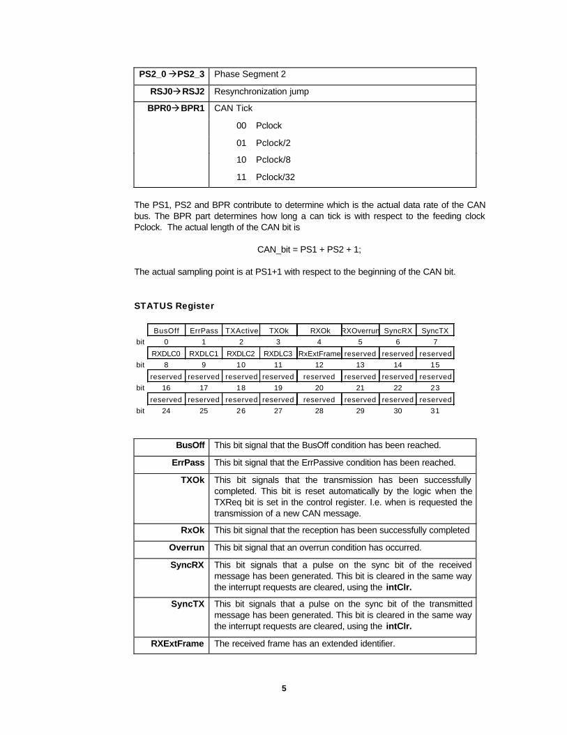
PS2_0 àPS2_3 Phase Segment 2
RSJ0àRSJ2 Resynchronization jump
CAN Tick
00 Pclock
01 Pclock/2
10 Pclock/8
BPR0àBPR1
11 Pclock/32
The PS1, PS2 and BPR contribute to determine which is the actual data rate of the CANbus. The BPR part determines how long a can tick is with respect to the feeding clockPclock. The actual length of the CAN bit is
CAN_bit = PS1 + PS2 + 1;
The actual sampling point is at PS1+1 with respect to the beginning of the CAN bit.
STATUS Register
BusOff ErrPass TXActive TXOk RXOk RXOverrun SyncRX SyncTXbit 0 1 2 3 4 5 6 7
RXDLC0 RXDLC1 RXDLC2 RXDLC3 RxExtFrame reserved reserved reservedbit 8 9 10 11 12 13 14 15
reserved reserved reserved reserved reserved reserved reserved reservedbit 16 17 18 19 20 21 22 23
reserved reserved reserved reserved reserved reserved reserved reservedbit 24 25 26 27 28 29 30 31
BusOff This bit signal that the BusOff condition has been reached.
ErrPass This bit signal that the ErrPassive condition has been reached.
TXOk This bit signals that the transmission has been successfullycompleted. This bit is reset automatically by the logic when theTXReq bit is set in the control register. I.e. when is requested thetransmission of a new CAN message.
RxOk This bit signal that the reception has been successfully completed
Overrun This bit signal that an overrun condition has occurred.
SyncRX This bit signals that a pulse on the sync bit of the receivedmessage has been generated. This bit is cleared in the same waythe interrupt requests are cleared, using the intClr.
SyncTX This bit signals that a pulse on the sync bit of the transmittedmessage has been generated. This bit is cleared in the same waythe interrupt requests are cleared, using the intClr.
RXExtFrame The received frame has an extended identifier.

6
RXDLC 0à3 DLC bit of the received message.
FILTER Register
AM0 AM1 AM2 AM3 AM4 AM5 AM6 AM7
bit 0 1 2 3 4 5 6 7AM8 AM9 AM10 reserved reserved reserved reserved reserved
bit 8 9 10 11 12 13 14 15AC0 AC1 AC2 AC3 AC4 AC5 AC6 AC7
bit 16 17 18 19 20 21 22 23AC8 AC9 AC10 reserved reserved reserved reserved reserved
bit 24 25 26 27 28 29 30 31
ACCEPTANCE MASK & CODE
The acceptance mask and code are used to filter out messages that are not of any interestfor the receiving software and therefore to decrease the software load. Both the“Acceptance Mask” and “Acceptance Code” are 16 bits long and only the first 16 bits ofthe message are taken into account for the filtering. The filtering works for both thestandard or extended CAN message frames. The formula applied is:
“Message ID” AND “Acceptance Mask” XOR “Acceptance Code” = 0 à Message valid
The filtering has no effect on the out-coming messages.
Message Buffers
The message buffers, both reception and transmission, have the arbitration part in the firstword. Please note that the ARB0 is actually the first bit transmitted of the arbitration part. Inthis respect the most significant bit convention is not respected for what regard thearbitration part, since the most significant bit is place in position 0.
TX Message
The TX message buffer is made by 13 bytes the meaning of which changes dependingfrom the fact that an extended frame is used or not.
Add WordARB0 ARB1 ARB2 ARB3 ARB4 ARB5 ARB6 ARB7
Bit 0 1 2 3 4 5 6 7
ARB8 ARB9 ARB10 ARB11 ARB12 ARB13 ARB14 ARB15Bit 8 9 10 11 12 13 14 15
ARB16 ARB17 ARB18 ARB19 ARB20 ARB21 ARB22 ARB23
Bit 8 9 10 11 12 13 14 15ARB24 ARB25 ARB26 ARB27 ARB28 reserved reserved reserved
0
Bit 8 9 10 11 12 13 14 15
Data Byte 0
Data Byte 11
Data Byte 2
7
Data Byte 3
Data Byte 0
Data Byte 1
Data Byte 22
Data Byte 3
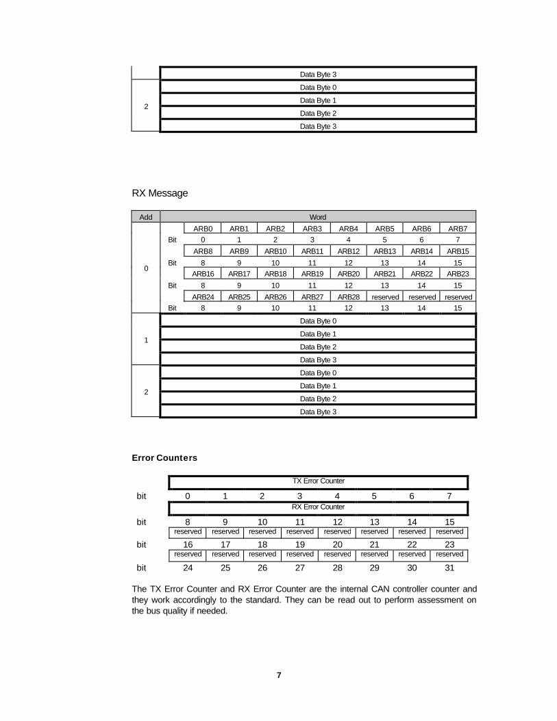
RX Message
Add Word
ARB0 ARB1 ARB2 ARB3 ARB4 ARB5 ARB6 ARB7Bit 0 1 2 3 4 5 6 7
ARB8 ARB9 ARB10 ARB11 ARB12 ARB13 ARB14 ARB15
Bit 8 9 10 11 12 13 14 15ARB16 ARB17 ARB18 ARB19 ARB20 ARB21 ARB22 ARB23
Bit 8 9 10 11 12 13 14 15
ARB24 ARB25 ARB26 ARB27 ARB28 reserved reserved reserved
0
Bit 8 9 10 11 12 13 14 15
Data Byte 0
Data Byte 1
Data Byte 21
Data Byte 3
Data Byte 0
Data Byte 1
Data Byte 22
Data Byte 3
Error Counters
TX Error Counter
bit 0 1 2 3 4 5 6 7RX Error Counter
bit 8 9 10 11 12 13 14 15reserved reserved reserved reserved reserved reserved reserved reserved
bit 16 17 18 19 20 21 22 23reserved reserved reserved reserved reserved reserved reserved reserved
bit 24 25 26 27 28 29 30 31
The TX Error Counter and RX Error Counter are the internal CAN controller counter andthey work accordingly to the standard. They can be read out to perform assessment onthe bus quality if needed.
8
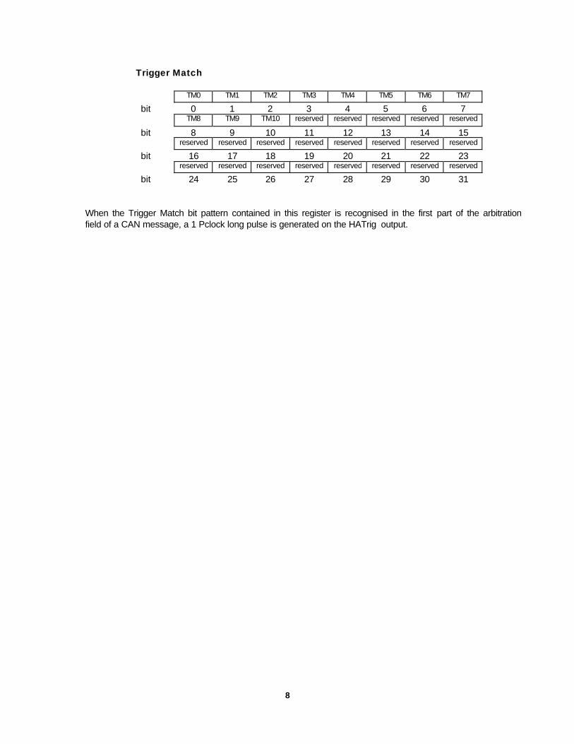
Trigger Match
TM0 TM1 TM2 TM3 TM4 TM5 TM6 TM7
bit 0 1 2 3 4 5 6 7TM8 TM9 TM10 reserved reserved reserved reserved reserved
bit 8 9 10 11 12 13 14 15reserved reserved reserved reserved reserved reserved reserved reserved
bit 16 17 18 19 20 21 22 23reserved reserved reserved reserved reserved reserved reserved reserved
bit 24 25 26 27 28 29 30 31
When the Trigger Match bit pattern contained in this register is recognised in the first part of the arbitration field of a CAN message, a 1 Pclock long pulse is generated on the HATrig output.

9
Appendix A
Time Synchronization
The Sync pulse present at the interface of the AMBA insterface is meant to allow the useof time distribution/synchronization around a CAN system. The method used is thefollowing: a time master maintain a very precise reference clock , while the rest of the CANnodes simply receives updates from time to time.The method to establish a common instant to the all network is using the issue of the syncbit of a CAN message. Each node has to register the time when this event has happenedand then to receive later the information of when this event has happened by the systemtime keeper.
Data Bus Switching
This part intends to suggest one possible use of the HATrig signal at the interface of thedevice. As explained before this signal is asserted as a pulse for a clock cycle uponreception of a CAN message with a pattern as specified in the “TRIGGER MATCH”register. The main idea behind this signal is to have a way of detecting low level signalswithout the involvement of the CPU and software. The mechanism can be used efficentlyto trigger a bus switch when the device is used in a system with two physical bus used asnominal and redundant.The HATrig must be connected to an external timer unit as a reset signal to trigger therestart of the counting process. If a triggering CAN frame, i.e. the CAN frame with anarbitration matching the “TRIGGER MATCH” register, is arriving regularly at an interval T,the timer will never reach a counting larger than T. If however the CAN frame with thetriggering arbitration is not arriving the timer will pass the interval T reaching a user setfinal value generating a signal to force the bus switching. (The signal of the timer can besimply used to control the enable pin of the transceiver).This mechanism, together with a CAN node regularly generating the appropriate CANframe, can be used to force a general CAN bus switch of which the CPU is not involved in.
10
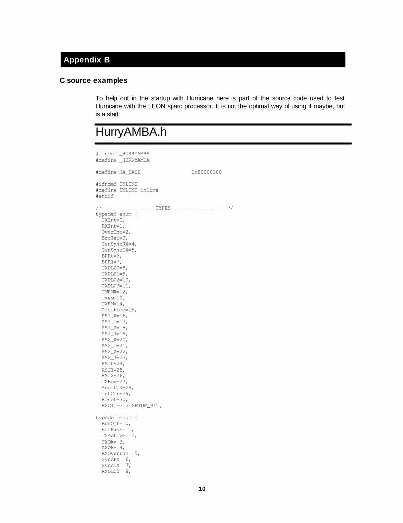
Appendix B
C source examples
To help out in the startup with Hurricane here is part of the source code used to testHurricane with the LEON sparc processor. It is not the optimal way of using it maybe, butis a start:
HurryAMBA.h
#ifndef _HURRYAMBA#define _HURRYAMBA
#define HA_BASE 0x80000100
#ifndef INLINE#define INLINE inline#endif
/* ---------------- TYPES ----------------- */typedef enum { TXInt=0, RXInt=1, OverInt=2, ErrInt=3, GenSyncRX=4, GenSyncTX=5, BPR0=6, BPR1=7, TXDLC0=8, TXDLC1=9, TXDLC2=10, TXDLC3=11, TMRMR=12, TXEM=13, TXRM=14, Disabled=15, PS1_0=16, PS1_1=17, PS1_2=18, PS1_3=19, PS2_0=20, PS2_1=21, PS2_2=22, PS2_3=23, RSJ0=24, RSJ1=25, RSJ2=26, TXReq=27, AbortTX=28, IntClr=29, Reset=30, RXClr=31} SETUP_BIT;
typedef enum { BusOff= 0, ErrPass= 1, TXActive= 2, TXOk= 3, RXOk= 4, RXOverrun= 5, SyncRX= 6, SyncTX= 7, RXDLC0= 8,
11
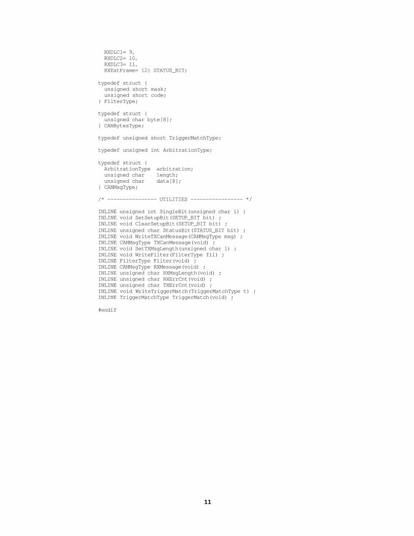
RXDLC1= 9, RXDLC2= 10, RXDLC3= 11, RXExtFrame= 12} STATUS_BIT;
typedef struct { unsigned short mask; unsigned short code;} FilterType;
typedef struct { unsigned char byte[8];} CANBytesType;
typedef unsigned short TriggerMatchType;
typedef unsigned int ArbitrationType;
typedef struct { ArbitrationType arbitration; unsigned char length; unsigned char data[8];} CANMsgType;
/* ---------------- UTILITIES ----------------- */
INLINE unsigned int SingleBit(unsigned char i) ;INLINE void SetSetupBit(SETUP_BIT bit) ;INLINE void ClearSetupBit(SETUP_BIT bit) ;INLINE unsigned char StatusBit(STATUS_BIT bit) ;INLINE void WriteTXCanMessage(CANMsgType msg) ;INLINE CANMsgType TXCanMessage(void) ;INLINE void SetTXMsgLength(unsigned char l) ;INLINE void WriteFilter(FilterType fil) ;INLINE FilterType Filter(void) ;INLINE CANMsgType RXMessage(void) ;INLINE unsigned char RXMsgLength(void) ;INLINE unsigned char RXErrCnt(void) ;INLINE unsigned char TXErrCnt(void) ;INLINE void WriteTriggerMatch(TriggerMatchType t) ;INLINE TriggerMatchType TriggerMatch(void) ;
#endif

12
HurryAMBA.c
#include "HurryAMBA.h"
INLINE unsigned int SingleBit(unsigned char i) { unsigned int b = 1;
if (i<32) { return b << i; }else return b << 31;};
INLINE void SetSetupBit(SETUP_BIT bit) { unsigned int *H = (unsigned int *)HA_BASE;
*H = *H | SingleBit(bit);};
INLINE void ClearSetupBit(SETUP_BIT bit) { unsigned int *H = (unsigned int *)HA_BASE;
*H = *H & ~SingleBit(bit);};
INLINE unsigned char StatusBit(STATUS_BIT bit) { unsigned int *H = (unsigned int *)(HA_BASE+4);
if (*H & SingleBit(bit)) return 1; else return 0;};
INLINE void WriteTXCanMessage(CANMsgType msg) { unsigned int *H = (unsigned int *)HA_BASE;
H[3] = msg.arbitration; H[4] = (((unsigned int)msg.data[3])<<24)| (((unsigned int)msg.data[2])<<16)| (((unsigned int)msg.data[1])<<8)| ((unsigned int)msg.data[0]); H[5] = (((unsigned int)msg.data[7])<<24)| (((unsigned int)msg.data[6])<<16)| (((unsigned int)msg.data[5])<<8)| ((unsigned int)msg.data[4]);};
INLINE CANMsgType TXCanMessage(void) { unsigned int *H = (unsigned int *)HA_BASE; unsigned int tmp; CANMsgType msg;
msg.arbitration = H[3]; tmp = H[4]; msg.data[0] = (unsigned char)(tmp >> 24); msg.data[1] = (unsigned char)(tmp >> 16); msg.data[2] = (unsigned char)(tmp >> 8); msg.data[3] = (unsigned char)(tmp); msg.data[4] = (unsigned char)(tmp >> 24); msg.data[5] = (unsigned char)(tmp >> 16); msg.data[6] = (unsigned char)(tmp >> 8); msg.data[7] = (unsigned char)(tmp);};
INLINE void SetTXMsgLength(unsigned char l) { unsigned int *H = (unsigned int *)HA_BASE;
if (l < 9) { if (l & 1) H[0] = H[0] | SingleBit(TXDLC0); if (l & 2) H[0] = H[0] | SingleBit(TXDLC1);
13
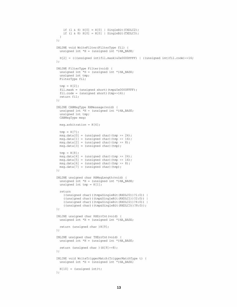
if (l & 4) H[0] = H[0] | SingleBit(TXDLC2); if (l & 8) H[0] = H[0] | SingleBit(TXDLC3); }};
INLINE void WriteFilter(FilterType fil) { unsigned int *H = (unsigned int *)HA_BASE;
H[2] = (((unsigned int)fil.mask)&0x0000FFFF) | ((unsigned int)fil.code)<<16;};
INLINE FilterType Filter(void) { unsigned int *H = (unsigned int *)HA_BASE; unsigned int tmp; FilterType fil;
tmp = H[2]; fil.mask = (unsigned short)(tmp&0x0000FFFF); fil.code = (unsigned short)(tmp>>16); return fil;};
INLINE CANMsgType RXMessage(void) { unsigned int *H = (unsigned int *)HA_BASE; unsigned int tmp; CANMsgType msg;
msg.arbitration = H[6];
tmp = H[7]; msg.data[0] = (unsigned char)(tmp >> 24); msg.data[1] = (unsigned char)(tmp >> 16); msg.data[2] = (unsigned char)(tmp >> 8); msg.data[3] = (unsigned char)(tmp);
tmp = H[8]; msg.data[4] = (unsigned char)(tmp >> 24); msg.data[5] = (unsigned char)(tmp >> 16); msg.data[6] = (unsigned char)(tmp >> 8); msg.data[7] = (unsigned char)(tmp);};
INLINE unsigned char RXMsgLength(void) { unsigned int *H = (unsigned int *)HA_BASE; unsigned int tmp = H[1];
return ((unsigned char)((tmp&SingleBit(RXDLC0))?1:0)) | ((unsigned char)((tmp&SingleBit(RXDLC1))?2:0)) | ((unsigned char)((tmp&SingleBit(RXDLC2))?4:0)) | ((unsigned char)((tmp&SingleBit(RXDLC3))?8:0));};
INLINE unsigned char RXErrCnt(void) { unsigned int *H = (unsigned int *)HA_BASE;
return (unsigned char )H[9];};
INLINE unsigned char TXErrCnt(void) { unsigned int *H = (unsigned int *)HA_BASE;
return (unsigned char )(H[9]>>8);};
INLINE void WriteTriggerMatch(TriggerMatchType t) { unsigned int *H = (unsigned int *)HA_BASE;
H[10] = (unsigned int)t;};

14
INLINE TriggerMatchType TriggerMatch(void) { unsigned int *H = (unsigned int *)HA_BASE;
return (TriggerMatchType )H[10];};

15
test.c
#define INLINE inline#include "HurryAMBA.c"
void initHurryAMBA(void) { ClearSetupBit(Disabled);};
void SendStdCANMessage(CANMsgType msg) { int i;
WriteTXCanMessage(msg); ClearSetupBit(TXEM); ClearSetupBit(TMRMR); ClearSetupBit(TXRM); SetTXMsgLength(msg.length); SetSetupBit(TXReq);};
void ReadCANMessage(CANMsgType *msg) { int i;
while(!StatusBit(RXOk)); *msg = RXMessage(); msg->length = RXMsgLength(); SetSetupBit(RXClr);};
int can_test() { CANMsgType msg;
initHurryAMBA(); msg.arbitration = 0xab; msg.length = 1; msg.data[0] = 0xcd; SendStdCANMessage(msg); while(!StatusBit(TXOk)); /* END */};