HUNTER - eMedia HUNTER™ Standard Tendon Implant consists primarily of a woven poly-ester core...
16
HUNTER Tendon Implants SURGICAL TECHNIQUE ™
Transcript of HUNTER - eMedia HUNTER™ Standard Tendon Implant consists primarily of a woven poly-ester core...

HUNTER
Tendon ImplantsSURGIC AL TECHNIQUE
™

HUNTER™
active TENDON IMPLANT
surgical technique 1–5
HUNTER™
passive TENDON IMPLANT
surgical technique 6–10

The HUNTER™ Active Tendon Implants consist primarily of an implant comprised of a polyester core covered with silicone elastomer (barium-impregnated for radiopacity). The HUNTER™ Active Tendon Implant is double-pouched, and is STERILE unless the inner pouch is opened or damaged.
The HUNTER™ Active Tendon Implants are indicated for use in stage one of the two-stage procedure developed by Dr. James M. Hunter for the recon-struction of flexor and extensor tendons in individuals having significant hand tendon injury. The device is intended to be implanted temporarily in order to encourage the formation of a pseudosynovial sheath which will later nourish and lubricate an autogenous tendon graft.
The interval between Stage One (implantation of the device and formation of the pseudosynovial sheath) and Stage Two (removal of the device and autogenous tendon grafting) should be two to six months to permit maturation of the tendon bed to the point where it can nourish and lubricate a tendon graft. The surgeon must determine, on the basis of the findings in the hand, the appropriate time within that period at which to commence Stage Two of the procedure. The HUNTER™ Active Tendon Implants are specifically indicated in cases in which proximal anastomosis must be executed deep in the proximal forearm. They may also be used, at the surgeon’s discretion, in patients having small pulleys which, unless opened surgically, will not permit insertion of a HUNTER™ Active Tendon Implant with a proximal loop.
This device is not intended for any use other than that indicated. Residual antecedent infection is a contraindication for the use of this device. Appropriate surgical and antimicrobial treatment and subsequent wound healing will allow the procedure to be carried out at a later date. A digit that has a scarred tendon bed, borderline nutrition, nerve deficit and severe joint stiffness could possibly be salvaged; however, this should probably be undertaken only in the patient with very special requirements. Subsequent functional expectations are limited.
a c t i v e T E N D O N I M P L A N T
device DESCRIPTIONS
indications
contraindications
F O R T E N D O N R E C O N S T R U C T I O N
o n e
H U N T E R ™ A C T I V E T E N D O N I M P L A N T
AT |
ATDC |
ATBC |
ATPC |
Complete indications, contraindications, warnings, and precautions are listed in the implant package insert and should be viewed by the physician and operating room personnel.
HUNTER ™

The following procedure is offered as an aid to the surgeon and is not intended to replace individual clinical judgment.
The following instructions for use of the HUNTER™ Active Tendon Implants are based on the surgical procedures employed by Dr. James M. Hunter, who participated in the development of the device. Note that only the methods for implantation and removal of the device are presented here.
STAGE ONE P R E P A R A T I O N1. The damaged flexor tendons and their scarred sheaths are exposed
by means of the Brunner zigzag incision in the finger and palm. The proximal portions of the flexor tendons and their musculotendinous junctions in the forearm are exposed by means of a curvilinear incision on the volar ulnar aspect of the forearm.
2. The retinacular pulley system should be preserved or reconstructed. An adequate, intact pulley system is essential for good function. When the retinacular pulley system is inadequate and bowstringing is noted, reconstruction of the system is indicated. Four pulleys are preferable (A1, A2a, b, A3, A4).
3. All scar tissue should be meticulously excised. The entire system from the proximal edge of A1 pulley to the distal phalanx should be exposed and explored. All remnants of the flexor tendons should be excised through multiple transverse incisions in the retinacular pulley systems. Contracted or scarred lumbrical muscle should also be excised in order to prevent paradoxical motion of the lumbricals after tendon grafting.
4. Undamaged portions of the flexor fibro-osseous retinacula which are not contracted are retained.
INSERTION OF THE ACTIVE IMPLANT5. Pass the device in a distal-to-proximal direction. Moistening the device
with sterile Ringer’s solution will facilitate this process. Advance the proximal cords through the pulleys and use the cords to gently pull the implant portion through.
6. Pass the device from palm to forearm through the carpal canal in a similar manner. Prepare the canal by passing a blunt metal obturator instrument (such as the Ober tendon passer) superficial to the profun-dus tendon and pull the polyester cords into the forearm. Use the cords to gently pull the implant portion through. Observe the distal fixation component and guide it to a position slightly proximal to its anticipated location over the phalanx.
instructions FOR USE
t w o
H U N T E R ™ A C T I V E T E N D O N I M P L A N T
Proper surgical techniques are nessarily the responsibility of the medical professional. The following guidelines are furnished only as recommended techniques. Each surgeon must evaluate the appropriateness of the techniques based on his or her own medical training and expertise.
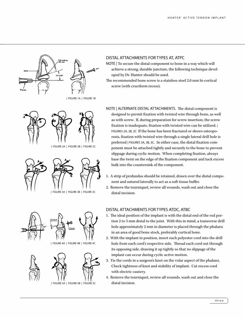
DISTAL ATTACHMENTS FOR TYPES AT, ATPCNOTE | To secure the distal component to bone in a way which will
achieve a strong, durable juncture, the following technique devel-oped by Dr. Hunter should be used.
The recommended bone screw is a stainless steel 2.0 mm bi-cortical screw (with cruciform recess).
NOTE | ALTERNATE DISTAL ATTACHMENTS. The distal component is designed to permit fixation with twisted wire through bone, as well as with screw. If, during preparation for screw insertion, the screw fixation is inadequate, fixation with twisted wire can be utilized. | FIGURES 2A, 2B, 2C If the bone has been fractured or shows osteopo-rosis, fixation with twisted wire through a single lateral drill hole is preferred | FIGURES 3A, 3B, 3C. In either case, the distal fixation com-ponent must be attached tightly and securely to the bone to prevent slippage during cyclic motion. When completing fixation, always base the twist on the edge of the fixation component and tuck excess bulk into the countersink of the component.
1. A strip of profundus should be retained, drawn over the distal compo-nent and sutured laterally to act as a soft tissue buffer.
2. Remove the tourniquet, review all wounds, wash out and close the distal incision.
DISTAL ATTACHMENTS FOR TYPES ATDC, ATBC1. The ideal position of the implant is with the distal end of the rod por-
tion 2 to 3 mm distal to the joint. With this in mind, a transverse drill hole approximately 2 mm in diameter is placed through the phalanx in an area of good bone stock, preferably cortical bone.
2. With the implant in position, insert each polyester cord into the drill hole from each cord’s respective side. Thread each cord out through its opposing side, drawing it up tightly so that no slippage of the implant can occur during cyclic active motion.
3. Tie the cords in a surgeon’s knot on the volar aspect of the phalanx. Check tightness of knot and stability of implant. Cut excess cord with electric cautery.
4. Remove the tourniquet, review all wounds, wash out and close the distal incision.
t h r e e
H U N T E R ™ A C T I V E T E N D O N I M P L A N T
| FIGURE 1A | FIGURE 1B
| FIGURE 2A | FIGURE 2B | FIGURE 2C
| FIGURE 3A | FIGURE 3B | FIGURE 3C
| FIGURE 4A | FIGURE 4B | FIGURE 4C
| FIGURE 5A | FIGURE 5B | FIGURE 5C

Pass the selected tendon through the implant loop (A), then through a small longitudinal split in the tendon (B). Place one suture through the tendon (C) and test the tension. Test tension by moistening the implant surface, followed by flexion and extension of the wrist. The finger should lay in extension during wrist flexion and show a position of balance with the adjacent fingers on wrist extension. If balance is acceptable, place a second suture and turn the tendon 90-degrees through one or two additional longitudinal splits in the tendon (D). Re-test tendon balance and be sure there has been no loss of tendon tension.
PROXIMAL ATTACHMENTS FOR TYPES ATPC, ATBC1. Select motor tendon: The profundus motor is of first preference, the
superficials, second. Desired excursion of the motor tendon is 4 cm for the FDP and 3 cm for the FDS.
2. The rod portion of the tendon can be shortened if necessary. With care, the silicone rubber can be peeled away from the polyester cord at the proximal end and trimmed with a scalpel. Care must be taken not to damage the polyester weave during this step. The two cords are attached by sewing crossing stitches of dacron from side to side. These stitches must be carefully cut to free the two dacron cords for the attachment to bone or tendon during the reconstructive surgery.
3. The proximal cords are woven into the lateral borders of the motor tendon and fixed with Mersilene sutures at points of exit. Approxi-mately 10 mm from the end of the motor tendon, make a small (2 to 3 mm) longitudinal slit in the lateral aspect of the motor tendon to al-low passage of a fine line curved hemostat. Insert the hemostat, with its tip moving distally, into the slit such that the tip exits from the end of the motor tendon | FIGURE 7A. Grasp the corresponding tendon cord with the hemostat and draw it back through | FIGURE 7B. Repeat the procedure on the opposite side. After each cord has been passed through the tendon one time, draw the tendon up so the proximal
f o u r
PROXIMAL ATTACHMENTS FOR TYPES AT, ATDC
1. Select motor tendon: The profundus motor is of first preference, the superficials, second. Length must be sufficient to pass through the proximal loop and return for at least two (2) 90-degree passes through the tendon. Desired excursion of the motor tendon is 4 cm for the FDP and 3 cm for the FDS.
2. Proximal juncture technique | FIGURE 6.
H U N T E R ™ A C T I V E T E N D O N I M P L A N T
| FIGURE 7A | FIGURE 7B | FIGURE 7C
| FIGURE 7D | FIGURE 7E
| FIGURE 6

edge of the rod is adjacent to the end of the tendon and secure each cord with a suture | FIGURE 7C. Test the tension by moistening the implant, followed by flexion and extension of the wrist. The finger should lie in extension during wrist flexion and show a position of balance with the adjacent fingers on wrist extension. If balance is acceptable, make two or three additional passes | FIGURE 7D, securing each with Mersilene suture. Retest tendon balance to be sure there has been no loss of tension. If balance is acceptable, the proximal cords can be tied securely and reinforced with 3-0 polyester sutures; excess proximal cord is cut with electric cautery | FIGURE 7E.
4. Wash out and close the proximal incision.5. NOTE | The Hunter Tendon silicone contains barium that gives an x-ray view
of the implant loosening or migrating.
HUNTER™ Active Tendon Implant | 4 mm Width AT164000 16 cm Long AT184000 18 cm Long AT204000 20 cm Long AT224000 22 cm Long
HUNTER™ Active Tendon Implant PC | 4 mm WidthATPC1640 16 cm Long ATPC1840 18 cm Long ATPC2040 20 cm Long ATPC2240 22 cm Long ATPC2640 26 cm Long
HUNTER™ Active Tendon Implant DC | 4 mm WidthATDC1640 16 cm Long ATDC1840 18 cm Long ATDC2040 20 cm Long ATDC2240 22 cm Long ATDC2640 26 cm Long
HUNTER™ Active Tendon Implant BC | 4 mm WidthATBC1640 16 cm Long ATBC1840 18 cm Long 2ATBC2040 0 cm Long ATBC2240 22 cm Long ATBC2640 26 cm Long
H U N T E R™
f i v e
H U N T E R ™ A C T I V E T E N D O N I M P L A N T
s i x
H U N T E R ™ P A S S I V E T E N D O N I M P L A N T
device DESCRIPTIONS
indications
contraindications
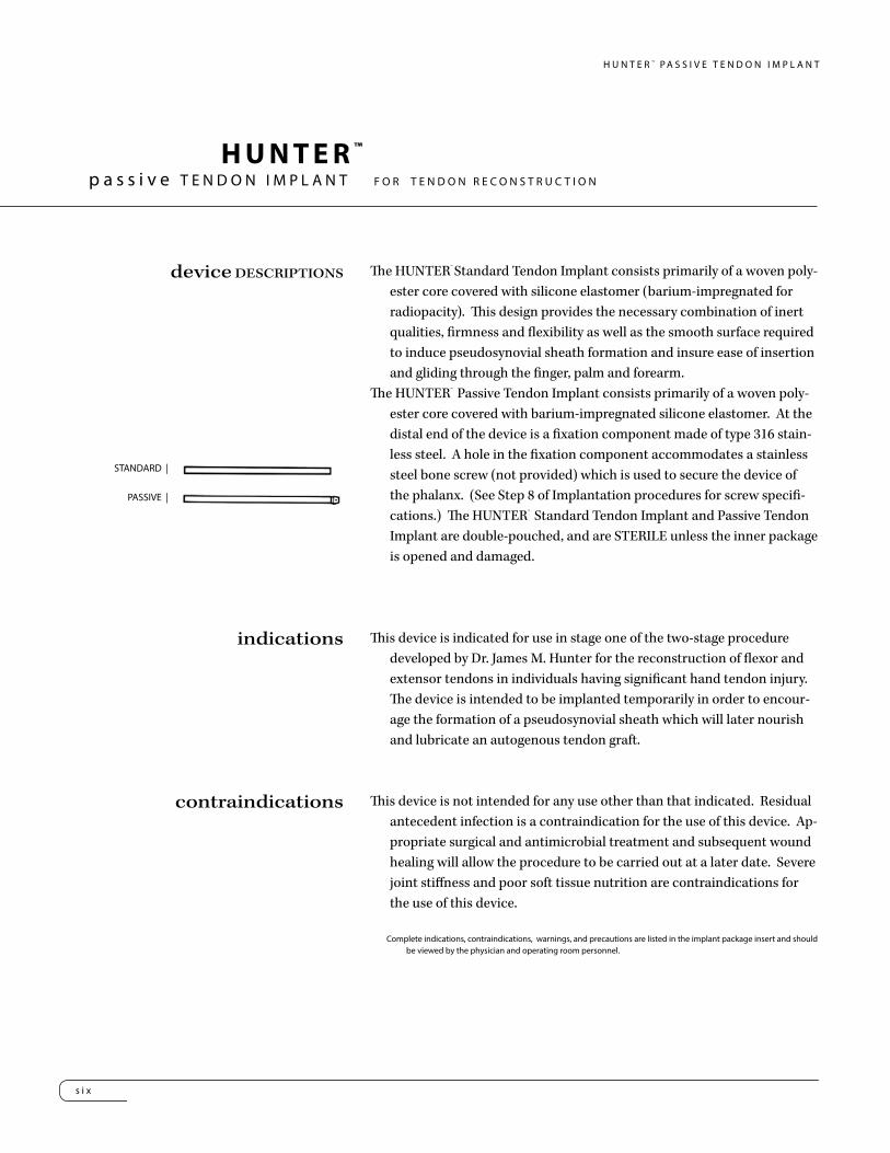
The HUNTER™ Standard Tendon Implant consists primarily of a woven poly-ester core covered with silicone elastomer (barium-impregnated for radiopacity). This design provides the necessary combination of inert qualities, firmness and flexibility as well as the smooth surface required to induce pseudosynovial sheath formation and insure ease of insertion and gliding through the finger, palm and forearm.
The HUNTER™ Passive Tendon Implant consists primarily of a woven poly-ester core covered with barium-impregnated silicone elastomer. At the distal end of the device is a fixation component made of type 316 stain-less steel. A hole in the fixation component accommodates a stainless steel bone screw (not provided) which is used to secure the device of the phalanx. (See Step 8 of Implantation procedures for screw specifi-cations.) The HUNTER™ Standard Tendon Implant and Passive Tendon Implant are double-pouched, and are STERILE unless the inner package is opened and damaged.
This device is indicated for use in stage one of the two-stage procedure developed by Dr. James M. Hunter for the reconstruction of flexor and extensor tendons in individuals having significant hand tendon injury. The device is intended to be implanted temporarily in order to encour-age the formation of a pseudosynovial sheath which will later nourish and lubricate an autogenous tendon graft.
This device is not intended for any use other than that indicated. Residual antecedent infection is a contraindication for the use of this device. Ap-propriate surgical and antimicrobial treatment and subsequent wound healing will allow the procedure to be carried out at a later date. Severe joint stiffness and poor soft tissue nutrition are contraindications for the use of this device.
STANDARD |
PASSIVE |
Complete indications, contraindications, warnings, and precautions are listed in the implant package insert and should be viewed by the physician and operating room personnel.
p a s s i v e T E N D O N I M P L A N T F O R T E N D O N R E C O N S T R U C T I O N
HUNTER ™

s e v e n
H U N T E R ™ P A S S I V E T E N D O N I M P L A N T
The following procedure is offered as an aid to the surgeon and is not in-tended to replace individual clinical judgment.
The following instructions for use of the HUNTER™ Standard Tendon Im-plant and Passive Tendon Implant are based on the surgical procedures employed by Dr. James M. Hunter, who participated in the development of the device. Note that only the methods for implantation and removal of the device are presented here.
IMPLANTATION OF THE HUNTER™ STANDARD TENDON IMPLANT/PASSIVE TENDON IMPLANT
1. The damaged flexor tendons and their scarred sheaths are exposed by means of the zigzag incision in the finger and palm. The proximal por-tions of the flexor tendons and their musculotendinous junctions in the forearm are exposed by means of an ulnarly curved volar incision. A stump of profundus tendon, one centimeter in length, is left attached to the distal phalanx.
2. Scarred tendons, sheath and retinacula are then excised. Contracted or scarred lumbrical muscle should also be excised in order to prevent paradoxical motion of the lumbricals after tendon grafting.
3. Undamaged portions of the flexor fibro-osseous retinacula which are not contracted are retained, as well as any portion of the retinacula that can be dilated instrumentally with a hemostat. The remainder is excised.
4. The retinacular pulley system should be preserved or reconstructed adjacent to the axis of motion of each joint to assure that normal gliding of the tendon will be restored. Four pulleys are preferable, one proximal to each of the three finger joints and one at the base of the proximal phalanx.
5. The device is placed on sponges moistened with sterile Ringer’s solution on the volar aspect of the forearm. A tendon passer, having a diameter slightly larger than that of the device, is passed proximally from the palm along the floor of the carpal tunnel into the forearm.
instructions FOR USE
Proper surgical techniques are nessarily the responsibility of the medical professional. The following guidelines are fur-nished only as recommended techniques. Each surgeon must evaluate the appropriateness of the techniques based on his or her own medical training and expertise.
e i g h t
H U N T E R ™ P A S S I V E T E N D O N I M P L A N T
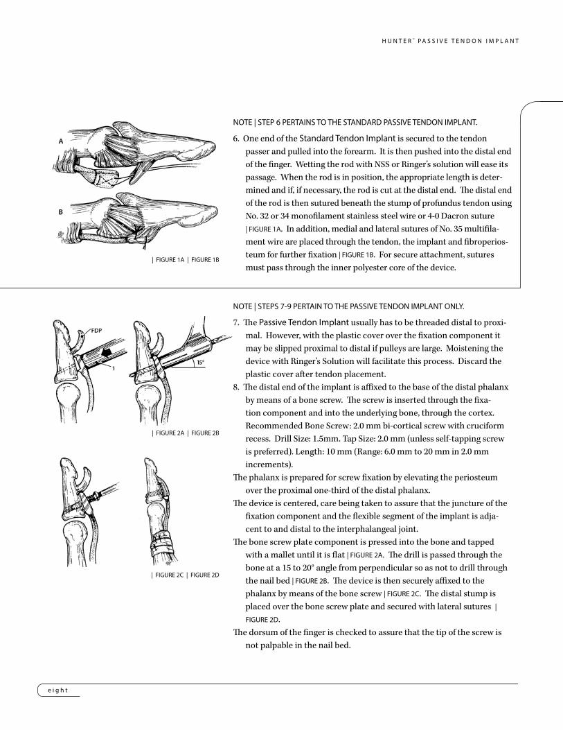
NOTE | STEP 6 PERTAINS TO THE STANDARD PASSIVE TENDON IMPLANT.
6. One end of the Standard Tendon Implant is secured to the tendon passer and pulled into the forearm. It is then pushed into the distal end of the finger. Wetting the rod with NSS or Ringer’s solution will ease its passage. When the rod is in position, the appropriate length is deter-mined and if, if necessary, the rod is cut at the distal end. The distal end of the rod is then sutured beneath the stump of profundus tendon using No. 32 or 34 monofilament stainless steel wire or 4-0 Dacron suture | FIGURE 1A. In addition, medial and lateral sutures of No. 35 multifila-ment wire are placed through the tendon, the implant and fibroperios-teum for further fixation | FIGURE 1B. For secure attachment, sutures must pass through the inner polyester core of the device.
NOTE | STEPS 7-9 PERTAIN TO THE PASSIVE TENDON IMPLANT ONLY.
7. The Passive Tendon Implant usually has to be threaded distal to proxi-mal. However, with the plastic cover over the fixation component it may be slipped proximal to distal if pulleys are large. Moistening the device with Ringer’s Solution will facilitate this process. Discard the plastic cover after tendon placement.
8. The distal end of the implant is affixed to the base of the distal phalanx by means of a bone screw. The screw is inserted through the fixa-tion component and into the underlying bone, through the cortex. Recommended Bone Screw: 2.0 mm bi-cortical screw with cruciform recess. Drill Size: 1.5mm. Tap Size: 2.0 mm (unless self-tapping screw is preferred). Length: 10 mm (Range: 6.0 mm to 20 mm in 2.0 mm increments).
The phalanx is prepared for screw fixation by elevating the periosteum over the proximal one-third of the distal phalanx.
The device is centered, care being taken to assure that the juncture of the fixation component and the flexible segment of the implant is adja-cent to and distal to the interphalangeal joint.
The bone screw plate component is pressed into the bone and tapped with a mallet until it is flat | FIGURE 2A. The drill is passed through the bone at a 15 to 20° angle from perpendicular so as not to drill through the nail bed | FIGURE 2B. The device is then securely affixed to the phalanx by means of the bone screw | FIGURE 2C. The distal stump is placed over the bone screw plate and secured with lateral sutures | FIGURE 2D.
The dorsum of the finger is checked to assure that the tip of the screw is not palpable in the nail bed.
| FIGURE 1A | FIGURE 1B
| FIGURE 2A | FIGURE 2B
| FIGURE 2C | FIGURE 2D

n i n e
H U N T E R ™ P A S S I V E T E N D O N I M P L A N T
NOTE | The same technique can be used for fixation of the device to the middle phalanx, except that the length of the bone screw used for fixation should be greater. This alternate procedure establishes sublimus tendon function, eliminating extensive surgery in certain scarred fingers, as well as assisting the surgeon and hand therapist with an easier postoperative training program. If the implant is attached to the middle phalanx, arthrodesis or tenodesis of the distal interphalangeal joint is required. | FIGURE 3. In cases where the bone is compromised by osteoporosis or fracture, the bone screw plate may be wired to the phalanx with stainless wire | FIGURE 4.
9. When the implant is in position, the appropriate length is determined and, if necessary, the device is cut at the proximal end.
10. When the distal end of the device has been fixed in place, traction is applied to the proximal end, to assure that the attachment of the device is distal to the distal interphalangeal joint and its volar plate and that there is no binding of the tendon during flexion and extension.
11. The device is also observed during passive flexion and extension of the finger, it should glide freely with no binding or buckling distal to any part of the pul-ley system. If free gliding does not occur, one of the pulleys may be too tight and modification of the pulley system may be necessary.
12. The proximal end of the device should lie in the forearm if possible so that the subsequently formed pseudosynovial sheath will extend to the region of the musculotendinous junction of the motor muscle. The device may be placed deep to the antebrachial fascia or deep in one of the intermuscular planes. The track for the device can be formed by separating connective tissue and tendon mesenteries with the moistened, gloved finger.
The track formed for the device must permit free passive gliding during flexion and extension of the finger. If this is not possible, the device must be short-ened so that when the finger is fully extended, the proximal end of the device lies just proximal to the flexion crease at the wrist.
13. Importantly, the surgeon under vision should look at the proximal end gliding and distal end fixation. Then the surgeon should put the patient in a passive range of motion to visually see continuous gliding and to visually check two places for problems. If there is difficulty in the range of motion, it is most likely a tight pulley which needs to be loosened or the implant is too long which can cause buckling.
14. Following skin closure, a standard postoperative hand dressing is applied, with the wrist and metacarphophalangeal joints in moderate flexion (40° to 50°) and the interphalangeal joints in slight flexion (20° to 30°).
15. NOTE | The Hunter Tendon silicone contains barium that gives an x-ray view of the implant loosening or migrating.| FIGURE 4
| FIGURE 3

t e n
H U N T E R ™ P A S S I V E T E N D O N I M P L A N T
REMOVAL OF THE STANDARD TENDON IMPLANT/PASSIVE TENDON IMPLANTNOTE | Details of management during the interval between implantation of the device and
formation of the pseudosynovial sheath (Stage I) and removal of the device and autog-enous tendon grafting (Stage II) are found in Hunter and Salisbury (1971), Hunter and Jaeger (1977), and the AAOS Symposium of Tendon Surgery in the Hand (1975). The in-terval between Stage I and Stage II should be two to six months, or long enough to permit maturation of the tendon bed to the point where it can nourish and lubricate a tendon graft. The surgeon must determine, on the basis of the findings in the hand, the appropri-ate time at which to commence Stage II of the procedure.
1. At operation, the limits of extension and flexion of the finger are measured and recorded.2. A short zigzag incision is made to locate the distal end of the device where it is attached
to the phalanx. This attachment is left intact and a second ulnarly curved volar incision is made through the previous Stage I incision in the forearm, so as to expose the proximal end of the device and the musculotendinous junc-tion of the superficialis or profundus tendon, whichever is to be used as a motor for the tendon graft.3. The excursion of the proximal end of the device, as the finger is moved from full exten-sion to full flexion, should be measured, so as to determine the amount of excursion that the motor muscle must have to provide full finger motion.4. Either the plantaris tendon or a long toe ex-tensor tendon is obtained from the leg for use as the tendon graft. 5. One end of the tendon graft is sutured to the proximal end of the device with catgut or polyester suture.6. Leaving the distal end of the device attached to the distal phalanx, the rest of the device, with the attached tendon graft, is pulled distally through the new sheath | FIGURE 5A. The de-vice is then removed and discarded.7. The Stage II procedure is completed by following established techniques for tendon grafting | FIGURE 5B.
| FIGURE 5A & B

H U N T E R™
e l e v e n
H U N T E R ™ P A S S I V E T E N D O N I M P L A N T
HUNTER™ Standard Tendon Implant | 24.5 cm Length
TR200000 2 mm Wide
TR300000 3 mm Wide
TR400000 4 mm Wide
TR600000 5 mm Wide
TR500000 6 mm Wide
HUNTER™ Passive Tendon Implant | 25 cm Length
PT300000 3 mm Wide
PT400000 4 mm Wide
PT500000 5 mm Wide
PT600000 6 mm Wide
SWANSON Tendon Spacer
24270003 24cm x 3mm
24270004 24cm x 4mm
24270005 24cm x 5mm
24270006 24cm x 6mm


™Trademarks and ®Registered marks of Wright Medical Technology, Inc. ©2014 Wright Medical Technology, Inc. All Rights Reserved. 010498_A-22-Jun-2014
Wright Medical Technology, Inc.1023 Cherry RoadMemphis, TN 38117800 238 7117901 867 9971www.wmt.com
Wright Medical EMEAAtlas Arena, Australia BuildingHoogoorddreef 71101 BA Amsterdamthe Netherlands011 31 20 565 9060