![Vibrotactile sense in median 071218 - lup.lub.lu.selup.lub.lu.se/search/ws/files/5318626/1057210.pdf · "Vibrotactile sense in median and ulnar nerve ... [large fibre neuropathy]](https://static.fdocuments.us/doc/165x107/5b1693297f8b9a4a6d8cc088/vibrotactile-sense-in-median-071218-luplubluseluplublusesearchwsfiles5318626.jpg)
Human-robot formation control via visual and vibrotactile...
14
1 Human-robot formation control via visual and vibrotactile haptic feedback Stefano Scheggi, Member, IEEE, Fabio Morbidi, Member, IEEE, and Domenico Prattichizzo, Member, IEEE Abstract—In this paper we present a new visuo-haptic interaction mechanism for human-robot formation control. The formation setup consists of a human leader and multiple follower robots. The mobile robots are equipped only with RGB-D cameras, and they should maintain a desired distance and orientation to the leader at all times. Mechanical limitations common to all the robots limit the possible trajectories that the human can take. In this regard, vibrotactile feedback provided by a haptic bracelet guides the human along trajectories that are feasible for the team by warning her/him when the formation constraints are being violated. Psychophysical tests on the bracelet together with real-world experiments conducted with a team of Pioneer robots show the effectiveness of the proposed visuo-haptic paradigm for the coordination of mixed human-robot teams. Index Terms—Haptic I/O, Design for wearability, Human-robot team, Vibrotactile feedback, Autonomous vehicles ✦ 1 I NTRODUCTION M OBILE robots hold a great promise in assisting people in a large variety of domains, including medical, military, recreational, and industrial appli- cations [1], [2]. Robots, indeed, can support humans in complex everyday tasks, such as indoor and out- door navigation, information supply and carrying of heavy objects. However, a mobile robot capable of reliably interacting with humans needs several ad- vanced skills such as detection of the targeted subject, recognition of the environment surrounding it, and collision avoidance. This paper considers a mixed human-robot team where a human leader is followed by a group of N unicycle robots (see Fig. 1). Recent studies [3], [4] have shown a close relationship between the shape of human locomotor paths in goal-directed movements, and the simplified kinematic model of a wheeled mobile robot. Thus, nonholonomic constraints similar to those of mobile robots seem to be at work when a human is walking: in particular, it has been shown in [3], [4] that the shoulders can be considered as a sort of steering wheel that drives the human body with a short delay (of about one fifth of a second). These results provided us with the theoretical ground for adapting the leader single-follower formation control strategy proposed in [5] for unicycles, to a mixed human-robot team. The team moves in an unstruc- tured environment, and the robots do not need any • S. Scheggi and D. Prattichizzo are with the Department of Information Engineering and Mathematics, University of Siena, 53100 Siena, Italy. D. Prattichizzo is also with the Department of Advanced Robotics, Istituto Italiano di Tecnologia, 16163 Genova, Italy. E-mail: {scheggi, prattichizzo}@dii.unisi.it • F. Morbidi is with the NeCS team, INRIA Grenoble Rhˆ one-Alpes, 38334 Montbonnot Saint-Martin, France. E-mail: [email protected] (c) (a) (b) robot 1 robot N Fig. 1. The proposed setup consists of a human leader (a), and a team of N mobile robots (b), solely equipped with RGB-D cameras. The robots estimate the human motion through the RGB-D sensors and use such information to follow the leader according to the formation parameters. A vibrotactile bracelet (c), warns the leader about potential violations of the formation constraints. a priori metric information about it. The goal of the robot followers is to maintain a certain desired distance and orientation with respect to the human leader at all times. Note that the non-rigid nature of the formations considered in [5] provides us with flex- ibility and robustness against noisy measurements. In the formation control strategy proposed in [5], the forward velocity of the robot leader and the curvature of its trajectory should respect suitable con- straints at all times. To achieve this goal in the mixed setup of this paper, our idea is to introduce a second communication channel between the follower robots and the human leader. In fact, the followers do not estimate only the human motion using the on-board RGB-D cameras, but they also send easily-processable information to the leader, e.g., to warn her/him that she/he is walking too fast and that the robots cannot
Transcript of Human-robot formation control via visual and vibrotactile...

1
Human-robot formation control via visual andvibrotactile haptic feedback
Stefano Scheggi, Member, IEEE, Fabio Morbidi, Member, IEEE,and Domenico Prattichizzo, Member, IEEE
Abstract—In this paper we present a new visuo-haptic interaction mechanism for human-robot formation control. The formationsetup consists of a human leader and multiple follower robots. The mobile robots are equipped only with RGB-D cameras, andthey should maintain a desired distance and orientation to the leader at all times. Mechanical limitations common to all the robotslimit the possible trajectories that the human can take. In this regard, vibrotactile feedback provided by a haptic bracelet guidesthe human along trajectories that are feasible for the team by warning her/him when the formation constraints are being violated.Psychophysical tests on the bracelet together with real-world experiments conducted with a team of Pioneer robots show theeffectiveness of the proposed visuo-haptic paradigm for the coordination of mixed human-robot teams.
Index Terms—Haptic I/O, Design for wearability, Human-robot team, Vibrotactile feedback, Autonomous vehicles
✦
1 INTRODUCTION
MOBILE robots hold a great promise in assistingpeople in a large variety of domains, including
medical, military, recreational, and industrial appli-cations [1], [2]. Robots, indeed, can support humansin complex everyday tasks, such as indoor and out-door navigation, information supply and carrying ofheavy objects. However, a mobile robot capable ofreliably interacting with humans needs several ad-vanced skills such as detection of the targeted subject,recognition of the environment surrounding it, andcollision avoidance.
This paper considers a mixed human-robot teamwhere a human leader is followed by a group of Nunicycle robots (see Fig. 1). Recent studies [3], [4]have shown a close relationship between the shape ofhuman locomotor paths in goal-directed movements,and the simplified kinematic model of a wheeledmobile robot. Thus, nonholonomic constraints similarto those of mobile robots seem to be at work whena human is walking: in particular, it has been shownin [3], [4] that the shoulders can be considered as a sortof steering wheel that drives the human body with ashort delay (of about one fifth of a second). Theseresults provided us with the theoretical ground foradapting the leader single-follower formation controlstrategy proposed in [5] for unicycles, to a mixedhuman-robot team. The team moves in an unstruc-tured environment, and the robots do not need any
• S. Scheggi and D. Prattichizzo are with the Department of InformationEngineering and Mathematics, University of Siena, 53100 Siena,Italy. D. Prattichizzo is also with the Department of AdvancedRobotics, Istituto Italiano di Tecnologia, 16163 Genova, Italy.E-mail: {scheggi, prattichizzo}@dii.unisi.it
• F. Morbidi is with the NeCS team, INRIA Grenoble Rhone-Alpes,38334 Montbonnot Saint-Martin, France.E-mail: [email protected]
(c)
(a)
(b)
robot 1
robot N
Fig. 1. The proposed setup consists of a humanleader (a), and a team of N mobile robots (b), solelyequipped with RGB-D cameras. The robots estimatethe human motion through the RGB-D sensors and usesuch information to follow the leader according to theformation parameters. A vibrotactile bracelet (c), warnsthe leader about potential violations of the formationconstraints.
a priori metric information about it. The goal ofthe robot followers is to maintain a certain desireddistance and orientation with respect to the humanleader at all times. Note that the non-rigid nature ofthe formations considered in [5] provides us with flex-ibility and robustness against noisy measurements.
In the formation control strategy proposed in [5],the forward velocity of the robot leader and thecurvature of its trajectory should respect suitable con-straints at all times. To achieve this goal in the mixedsetup of this paper, our idea is to introduce a secondcommunication channel between the follower robotsand the human leader. In fact, the followers do notestimate only the human motion using the on-boardRGB-D cameras, but they also send easily-processableinformation to the leader, e.g., to warn her/him thatshe/he is walking too fast and that the robots cannot

2
keep up. In this way, the cohesiveness and reactivityof the team can be significantly improved.
Noninvasive human-robot interaction can be easilyachieved via a wearable haptic device that providesvibrotactile feedback to the user. In fact, visual andauditory channels may be overloaded with informa-tion, thus resulting in a rapid error increase and ina consequent reduction in overall user performance.A possible solution to this problem is to deliverthis information through an underutilized sensorychannel. As with sound, a tactile stimulus is made upof a signal with varying frequency and amplitude, butdifferently from the auditory feedback which needsa mental model in order to parse the information,tactile feedback directly engages our motor learningsystem [6]. While kinesthetic feedback is commonin haptic systems, vibrotactile feedback is used inthis work because tactile devices are generally moreportable and less encumbering than kinesthetic de-vices and have a wider range of action [7].
In this paper an intuitive haptic bracelet is designedto correct the trajectory of the human leader, accord-ing to the formation specifics. The proposed setuppresents significant advantages: (i) the robots areminimally equipped: they have only an off-the-shelfRGB-D camera onboard, e.g., Microsoft’s Kinect, fromwhich they obtain all the information necessary toimplement their control law (however, other sensors,such as time-of-flight (ToF) cameras, could be used aswell for the same purpose); (ii) differently from [5]no global information is needed, i.e., each followerrequires only the pose of the human leader withrespect to its local reference frame; (iii) the setupis modular and scalable: in fact, since each robot isuniquely engaged with the leader, new followers canbe easily added or removed from the team.
This work is based in part on previous conferencematerial [8] compared to which we provide herein anew and improved prototype of the haptic bracelet,a robust visual human-tracking algorithm, a moreextended theory and a more comprehensive experi-mental validation.
1.1 Related work and organization
Several recent works have studied human-robot inter-action in leader-follower systems: however, none ofthem considered human multi-robot cooperation viahaptic feedback.
In [9] the authors proposed a laser-based person-tracking method and investigated the social percep-tion of a robot’s movement as it follows the human.The authors designed two person-following modesand analyzed which one is more natural and so-cially acceptable. The tracking method is based on asingle laser range finder and a simple proportionalfeedback control is employed based on the error be-tween the robot’s current distance to the person andthe desired distance. The robot notifies the personif she/he is walking too fast by using synthesized
computer speech. Closely related is the work in [10]where the authors presented a robotic system capableof person following and responding to verbal andnon-verbal commands in the presence of varyinglighting conditions and uneven floor. In particular,they used a real-time depth map obtained from aCSEM SwissRanger ToF camera which can properlywork both in total darkness and in bright light, andleveraged a PID controller and a Kalman filter for theperson following and estimation tasks, respectively.The user communicates with the robot using a set ofpredefined gestures and a verbal vocabulary while therobot verbally reports its status to her/him. In [11],the authors dealt with human-machine interaction in astructured environment using multiple intelligent sen-sors. The sensor network recognizes the human targetand the mobile robot, and provides control commandsto it. A virtual spring model is used for describingthe interaction between the human and the mobilerobot, which guarantees smooth control inputs andgood target-tracking performance. Although multiplerobots can be potentially used, the authors focusedon a single robot interacting with a human. Moreoverthe assumption of a structured environment plays acrucial role in this approach. Recently, experimentson the coordination of human-robot teams have beencarried out in [12]: this represents one of the firstattempts of human guidance via decentralized controlof a team of robots. However, differently from ourwork the authors mainly focused on the formationcontrol design, and they did not exploit the non-holonomic nature of human locomotion. Finally, itis worth mentioning [13] where the authors studiedhuman-robot teams for exploring an unmapped in-door area. The human carries an IMU sensor whichis devoted to localization and tracking in conjunctionwith laser range finders mounted on the robots anda laptop which is used to display visual informationto her/him. When compared with our approach basedon a simple vibrotactile bracelet, this solution is seem-ingly bulkier and less practical.
Regarding the haptic feedback, most of the exist-ing research on cutaneous stimulation has focused onproviding stimuli on human finger pads, due to thehigh number of receptors located there. Recent works,however, have started to explore other body parts forinformation display. In particular, vibrotactile deviceshave been mainly used to adjust the posture of specificportions of the body. For example, in [6] the authorsdeveloped a robotic suit for improved human motorlearning, which provides vibrotactile feedback pro-portional to the error between the effective and thelearned motion. Closely related is the work in [14],which presents a wearable robotic teacher for guidingforearm movements. The system provides vibrotactilestimuli through a bracelet composed of four vibra-tion motors disposed in quadrants. Along the sameline, in [15], a physiological study was conductedto verify the effectiveness of different wrist-worn
3
tactor placements for delivering spontaneous alertsand notifications to human subjects. A vibrotactileorientation guidance device was proposed in [16].The authors mainly focused here on the layout ofthe device as well as on the generation of differentvibration patterns. Finally in [17], an evaluation of fivetactile devices for wrist rotation guidance was pre-sented. Closer to our research are [18], [19] where theauthors studied the possibility of presenting guidanceinformation on a vibrotactile waist belt integratedwith a directional sensor and a GPS system. Resultsindicated the usefulness of tactile feedback for navi-gation purposes as well as for situational awarenessin multi-task environments. However, [18], [19] donot consider the vibrotactile feedback as a possiblecommunication channel for human-robot interaction.
Differently from the papers mentioned above, inthis work we consider a mixed formation where mul-tiple follower robots track a human leader using onlytheir on-board RGB-D cameras. The nonlinear controlstrategy proposed in [5] has been adapted to theparticular setup considered in this paper, and an ad-ditional communication channel has been introducedbetween the human leader and the followers: simplevibrotactile signals delivered by a custom-designedhaptic bracelet are used to warn the leader aboutpotential violations of the formation constraints.
The rest of the paper is organized as follows. Sect. 2reviews the formation control strategy presented in [5]and introduces a simple collision-avoidance policyfor the followers. Sect. 3 presents our method fordetecting and tracking a human subject using anRGB-D camera. Sect. 4 describes the main featuresof our haptic bracelet. In Sect. 5 we validate theproposed algorithms via extensive numerical testsand real-world experiments. Finally, in Sect. 6 wesummarize the main contributions of the paper, anddiscuss possible avenues for future research.
2 LEADER-FOLLOWER FORMATIONCONTROL STRATEGY
In this section we briefly review the leader-followerformation control strategy proposed in [5] that weadapt to our mixed human-robot setup. In particular,instead of considering the robot’s pose expressed ina global reference frame as in [5], the position andorientation of the leader will be here estimated in thefollowers’ reference frames.
We assume that a robot R = (x, y, θ)T with initialpose R ∈ R
2 × S1 and control (v, ω)T ∈ R>0 × R
satisfies, {x = v cos θ, y = v sin θ, θ = ω,
(x(0), y(0), θ(0))T = R.
We set κ(t) = ω(t)/v(t) which is the curvature ofthe path followed by the robot at time t. Denote byP(t) = (x(t), y(t))T the position of R at time t, θ(t) itsheading, τ (θ) = (cos θ, sin θ)T the normalized velocityvector and ν(θ) = (− sin θ, cos θ)T the normalized
Ri = (0, 0, 0)T
φi
θ0
R0 = (PT0 , θ0)T
di
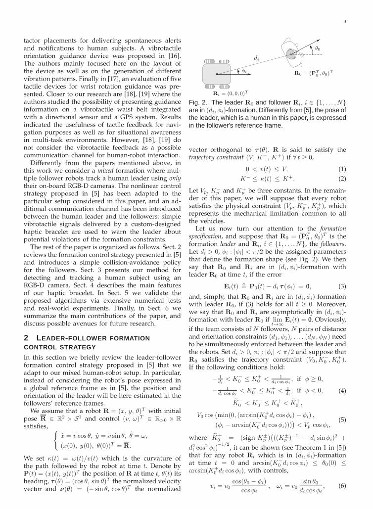
Fig. 2. The leader R0 and follower Ri, i ∈ {1, . . . , N}are in (di, φi)-formation. Differently from [5], the pose ofthe leader, which is a human in this paper, is expressedin the follower’s reference frame.
vector orthogonal to τ (θ). R is said to satisfy thetrajectory constraint (V, K−, K+) if ∀ t ≥ 0,
0 < v(t) ≤ V, (1)
K− ≤ κ(t) ≤ K+. (2)
Let Vp, K−p and K+
p be three constants. In the remain-der of this paper, we will suppose that every robotsatisfies the physical constraint (Vp, K
−p , K+
p ), whichrepresents the mechanical limitation common to allthe vehicles.
Let us now turn our attention to the formationspecification, and suppose that R0 = (PT
0 , θ0)T is the
formation leader and Ri, i ∈ {1, . . . , N}, the followers.Let di > 0, φi : |φi| < π/2 be the assigned parametersthat define the formation shape (see Fig. 2). We thensay that R0 and Ri are in (di, φi)-formation withleader R0 at time t, if the error
Ei(t) , P0(t)− di τ (φi) = 0, (3)
and, simply, that R0 and Ri are in (di, φi)-formationwith leader R0, if (3) holds for all t ≥ 0. Moreover,we say that R0 and Ri are asymptotically in (di, φi)-formation with leader R0 if lim
t→∞Ei(t) = 0. Obviously,
if the team consists of N followers, N pairs of distanceand orientation constraints (d1, φ1), . . . , (dN , φN ) needto be simultaneously enforced between the leader andthe robots. Set di > 0, φi : |φi| < π/2 and suppose thatR0 satisfies the trajectory constraint (V0,K
−0 ,K+
0 ).If the following conditions hold:
− 1di
< K−0 ≤ K+
0 < 1di cosφi
, if φ ≥ 0,
− 1di cosφi
< K−0 ≤ K+
0 < 1di, if φ < 0,
K−0 < K−
0 ≤ K+0 < K+
0 ,
(4)
V0 cos(min(0, (arcsin(K+
0 di cosφi)− φi) ,
(φi − arcsin(K−0 di cosφi)))
)< Vp cosφi,
(5)
where K±0 = (sign K±
p )(((K±
p )−1 − di sinφi)2 +
d2i cos2 φi
)−1/2, it can be shown (see Theorem 1 in [5])
that for any robot Ri which is in (di, φi)-formationat time t = 0 and arcsin(K−
0 di cosφi) ≤ θ0(0) ≤arcsin(K+
0 di cosφi), with controls,
vi = v0cos(θ0 − φi)
cosφi, ωi = v0
sin θ0di cosφi
, (6)

4
then R0 and Ri are in (di, φi)-formation and ∀ t ≥ 0,arcsin(K−
0 di cosφi) ≤ θ0(t) ≤ arcsin(K+0 di cosφi).
Geometrically speaking, this means that Ri lies inan arc of circle centered at the leader with orienta-tion θ0 + φ + π and aperture arcsin(K+
0 di cosφi) −arcsin(K−
0 di cosφi) at all times (see Fig. 2 in [5]).In this respect, the formations considered in this paperhave the special property of being non-rigid [20].
Let us now address the problem of stabilizing theleader-follower formation (i.e., we assume here thatthe robots are not initially in formation). Let R0 be theformation leader satisfying the trajectory constraint(V0,K
−0 ,K+
0 ). If conditions (4) and (5) hold, and (seeTheorem 2 in [5]),
0 < W0 ≤ v0(t), (7)
then for each follower Ri there is ǫ > 0 such that forany ǫ : 0 < ǫ < ǫ, there exist suitable controls vi, ωi,
vi(t) =
Vp, if θ0(t) /∈ Γǫ,v0(t) cos(θ0(t)−φi)+ηi(t) 〈Ei(t), τ(φi)〉
cosφi,
if θ0(t) ∈ Γǫ,
(8)
ωi(t) =
Vp K+p , if θ0(t) /∈ Γǫ and K+
p ≥ 0,
Vp K−p , if θ0(t) /∈ Γǫ and K+
p < 0,v0(t) sin(θ0(t)+ηi(t) 〈Ei(t), ν(0)〉
di cosφi, if θ0(t) ∈ Γǫ,
(9)where Γǫ = {x ∈ S1|(K−
0 − ǫ) di cosφi ≤ sinx ≤ (K+0 +
ǫ) di cosφi}, Ei(t) is defined in (3), 〈·, ·〉 denotes thescalar product and ηi(t) is given by
ηi(t) = min( (v0 −W0/2) cos(θ0 − φi)
|〈Ei(t), τ (φi)〉|,
[min((K+
0+ ǫ/2− κ0), (κ0 − (K−
0− ǫ/2))] di cosφi
|〈Ei(t), ν(0)〉|,
Vp cos φi − v0 cos(θ0 − φi)
|〈Ei(t), τ (φi)〉|,
v0K+
p di cos(θ0 − φi)− sin θ0
|〈Ei(t), ν(0)〉| + |K+p ||〈Ei(t), τ (φi)〉|
,
v0sin θ0 −K−
p di cos(θ0 − φi)
|〈Ei(t), ν(0)〉| + |K−
p ||〈Ei(t), τ (φi)〉|,M
)
,
being M > 0 a gain constant (with the convention that1/0 = +∞), such that R0 and Ri are asymptoticallyin (di, φi)-formation and ∃ t ≥ 0 : ∀ t ≥ t, arcsin((K−
0 −ǫ) di cosφi) ≤ θ0(t) ≤ arcsin((K+
0 + ǫ) di cosφi). Notethat the stabilizing controller (8)-(9) allows the fol-lower Ri to be asymptotically in (di, φi)-formation ifthe leader R0 satisfies the inequalities (4), (5) and (7),and that the positive constant W0 in (7) is usedto keep v0(t) away from zero. The control strategyessentially consists of two steps: in the first step Ri
moves with maximal linear and angular velocitiesuntil its direction is sufficiently close to that of theleader, while in the second step Ri uses (6) with anadded stabilizing term in order to reduce the errorasymptotically to zero. As it will become clearer inthe next section, in our setup each follower is able to
locally compute its control law by only relying on theinformation provided by its on-board sensor.
In order to avoid possible collisions between thefollowers, inspired by [21] let us define,
(vi(t), ωi(t))T =
(Vp, −λ
∑
j
ϑj, A
)T, (10)
if j is such that ‖(ixj ,i yj)
T ‖ ≤ rd and set vi(t),ωi(t) as in (8), (9) if ‖(ixj ,
i yj)T ‖ > rd, ∀ j 6= i,
where ϑj, A , atan2(iyj ,i xj) with (ixj(t),
i yj(t))T the
position of robot Rj in the reference frame of robotRi at time t, λ is a positive gain, and rd is the radiusof the collision avoidance disk centered at Ri. In otherwords, if all the other followers are outside its colli-sion avoidance disk, robot Ri applies the standardstabilizing control and formation maintenance hasthe highest priority: otherwise, it adjusts its angularvelocity according to the position of the follower(s)Rj inside its avoidance disk and keeps its forwardvelocity constant.
Notice that Eq. (4)-(5), (7) introduce a useful map-ping between the constraints of the N robots and thebounds on the linear velocity and curvature of theleader. In fact, each robot has constraints which arerelated to its formation parameters (di, φi) and to itsmechanical limitations (Vp, K
−p , K+
p ). If we considera formation of N robots, it would be impracticaland confusing for the user to receive haptic stimuliwhich notify the violation of each constraint of the Nrobots. The proposed mathematical formulation triesto “compress” as much as possible the informationrelative to the constraints of each robot without prej-udicing too much the level of informativeness. Ourmapping between the constraints of the N robots andthe bounds on velocities of the leader allows us touse simple haptic stimuli which must elicit three basicbehaviors: turn left, turn right and slow down.
In the next section we will present our visualhuman-detection mechanism, and in Sect. 4 we willshow how vibrotactile signals produced by a hapticbracelet can be used to correct the trajectory of theleader according to the formation specifics.
3 VISUAL DETECTION AND TRACKING OFTHE LEADER
This section provides an overview of the major stepsof our method for detecting the human leader fromthe visual information provided by the RGB-D cam-eras onboard the follower robots. In what follows, wewill assume that the robot xy-plane is parallel to thefloor. As a preliminary step, we perform an extrinsiccalibration of the RGB-D camera and robot referenceframes. The homogeneous matrix H
RK , that relates
the robot frame (R) with the camera frame (K), isestimated using a custom algorithm derived from [22].The main motivation for this preliminary step is thatthe formation control strategy described in Sect. 2is computed with respect to the robots’ center, so itis necessary to express the input data in the robots’

5
(a) (b) (c) (d)
Fig. 3. Human-body detection method on real data. (a) The initial point cloud is downsampled, and expressedin the robot frame. (b) Data points which lie outside a given box are removed, while the remaining points areprojected onto the robot xy-plane, and a clustering filter is applied (c). The position and orientation of the humanbody is detected through ellipse fitting (d).
frames. Given an input point cloud of the scene, wefirst downsample the data using a voxel grid filterwith a leaf size of 2 cm (see Fig. 3(a)). We thenexpress the downsampled point cloud P
K in the robotreference frame using the estimated homogeneousmatrix P
R = HRK P
K where PR represents the scene
points in the robot frame. We discard all points thatlie outside a given bounding box (Fig. 3(b)). As pre-viously mentioned in [3], [4], since the shoulders canbe considered as a sort of steering wheel that drivesthe human body with a delay of 0.2 s, in the detectionphase we are mainly interested in recognizing thehuman torso. In this regard, we discard all the pointswhich lie below the hip of the subject. We then projectthe points onto the robot xy-plane, and perform acluster filtering discarding those clusters whose di-mension is outside a given range (Fig. 3(c)). Finally,an ellipse fitting is performed over the clusters. Weconsider the human body as the cluster that best fitsthe ellipse, having the origin of the reference framecoincident with the ellipse center (Fig. 3(d)). Usingthis approach, the range in which the person can bedetected and tracked is approximately between 0.8 mand 5.3 m in front of the Kinect.
Note that once the human body has been identifiedin the initial frame, to facilitate the human trackingin the successive frames, the bounding box can beupdated (in terms of orientation, position and di-mension) in order to define a proper region centeredat the person. The proposed approach is robust tointerferences in the depth image caused by multipleRGB-D devices observing the same scene.
4 HAPTIC FEEDBACK
In this section, we describe the main features ofour haptic bracelet and the nature of the vibrotactilefeedback provided to the human. We also present theresults of an experimental study that we conducted toassess how the stimuli produced by the bracelet areperceived by humans.
4.1 Description of the haptic braceletStudies have demonstrated that vibration is best onhairy skin due to skin thickness and nerve depth,
and that vibrotactile stimuli are best detected in bonyareas [23]. In particular, wrists and spine are generallypreferred for detecting vibrations, with arms nextin line [24], [25]. Movement can decrease detectionrate, and increases response time of particular bodyareas [26]. For example, walking affects lower bodysites the most [25].
Since in our setup the haptic feedback will providethe leader with information about the constraints onher/his linear and angular velocities, three vibratingmotors are utilized to independently warn the user.Recent studies have demonstrated that a braceletshape with three vibrating motors circling the forearmensures sufficient distance between the motors whilecovering a minimal forearm area [16]. In fact, theminimal distance between two stimuli to be differ-entiated is about 35 mm on the forearms: in two-point discrimination perception there is no evidencefor differences among the left and right sides of thebody, and women are known to be more sensitive thanmen to skin stimulation [23], [27]. Following theseguidelines, we designed a wearable haptic braceletin which three cylindrical vibro-motors, L (left), C(center) and R (right) are independently controlled viaan external PC using the Bluetooth communicationprotocol: the motors generate vibratory signals towarn the human of potential violations of forma-tion constraints (see Fig. 4). The communication isrealized with an RN42 Bluetooth module connectedto an Arduino mini pro 3.3 V with a baud rate of9600. An Atmega 328 microcontroller installed on theArduino board is used to independently control thevibration amplitude of each motor. Although tactilestimulations under 100 Hz improve the spatial res-olution of the vibration’s perception [28], the max-imal sensitivity is achieved around 200-300 Hz [29](the human perceptibility range is between 20 and400 Hz). Three Precision Microdrives 303-100 PicoVibe 3.2 mm vibration motors were placed into threefabric pockets on the external surface of the bracelet(the width of the wristband is about 60 mm), withshafts aligned with the elbow bone. Since the rotatingmasses are exposed, we placed each motor inside acylindrical case of ABS plastic in order to protect

6
(a)
(a)(a)
(a)
(b)
(c)
Fig. 4. Human-robot interaction is achieved via a vibro-tactile bracelet equipped with three vibrating motors,(a), attached to an elastic wristband (b). The Li-Ionbattery and the Arduino board are in (c).
them from damage and guarantee a correct operation.The motors have a vibration frequency range of 100-280 Hz and a vibration amplitude of 0.6 g with a100 gram inertial test load at rated voltage of 3 V,where g = 9.81 m/s2. Although more sophisticatedbracelets have been recently proposed in the literature(see for example [30]), our goal was to design aninexpensive and mechanically simple device capableof producing easily-reproducible results.
4.2 Generation of the vibrotactile feedback
Our vibrotactile feedback simply consists in activatingthe vibro-motors when the formation constraints areabout to be violated (with a given threshold), and inincreasing the vibration frequency proportionally tothe constraint violation (increasing intensity improvesthe detection rate and reduces the reaction time [25]).A repulsive haptic-feedback mechanism was adopted.A special case occurs when a robot performs an eva-sive maneuver (Eq. (10)) in order to avoid collisionswith the other followers: since the robot does not usethe stabilizing formation control law, its contributionwill not be considered in the notification of formation-constraint violation.
Let fm, fM be the minimal and maximal vibrationfrequency of each motor, respectively, and fj(t) thevibration frequency of motor j ∈ {L,C,R} at time t.As discussed in Sect. 2, the leader should respectboth velocity and curvature constraints. The curvatureconstraints involve the activation of motors L andR in the bracelet, while the velocity constraints aredisplayed through motor C. The curvature of the pathfollowed by the leader at time t is κ0(t) = ω0(t)/v0(t)with v0(t) > 0. Substituting (2) in (4) and introduc-ing the curvature threshold αc ∈ R>0, we obtain thefollowing curvature constraints for each follower Ri,i ∈ {1, . . . , N} (di > 0, φi : |φi| < π/2, cf. Sect. 2),− 1
di< − 1
di+ αc ≤ κ0(t) ≤ 1
di cosφi− αc < 1
di cosφi,
if φi ≥ 0 and − 1di cosφi
< − 1di cosφi
+ αc ≤ κ0(t) ≤1di
− αc < 1di
, if φi < 0. These constraints can becombined to yield the following formation curvatureconstraints,
maxi
(− 1di
+ αc) ≤ κ0(t) ≤ mini( 1di cosφi
− αc), if φi ≥ 0,
maxi
(− 1di cosφi
+ αc) ≤ κ0(t) ≤ mini( 1di
− αc), if φi < 0.
(11)This means that in the case that two or more violationsof the same constraint are simultaneously detected,a vibrational signal corresponding to the constraintwhich is violated the most is generated.Let δ+(t), δ−(t) be the amount of violation of thegiven constraints at time t, when ω0(t) is positive ornegative, respectively. From (11) we obtain,
δ+(t) =
κ0(t)−mini( 1di cosφi
− αc), if φi ≥ 0,
κ0(t)−mini( 1di
− αc), if φi < 0,
δ−(t) =
max
i(− 1
di+ αc)− κ0(t), if φi ≥ 0,
maxi
(− 1di cosφi
+ αc)− κ0(t), if φi < 0.
If max(δ+(t), δ−(t)) ≥ 0, the human is about to violatethe curvature constraints and hence the followingvibrational feedback is generated by the motors,
fj(t) = (fM − fm)max(δ+(t), δ−(t))
αc+ fm, (12)
with j = L if δ+(t) ≥ 0 and j = R if δ−(t) ≥ 0.As far as the linear velocity of the human leader isconcerned, from (1), (7) and introducing a velocitythreshold value αl ∈ R>0, we obtain that v0(t) shouldfulfill the following constraint,
0 < W0 < v0(t) < V0 − αl < V0, (13)
where V0 satisfies equation (5) for each follower Ri.If the leader is moving too fast, i.e., v0(t) ≥ V0 − αl,the amount of constraint violation is β+(t) = v0(t) −V0 +αl, and a vibration with the following frequencyis generated by motor C:
fC(t) = (fM − fm)β+(t)
αl+ fm. (14)
Note that constraint (13) also specifies a lower boundW0 for the linear velocity v0(t). However, W0 canbe set arbitrarily small so that this bound is neverviolated in practice.
Remark 1: Since v0(t) > 0, the constraint on thecurvature can be considered as a constraint onthe angular velocity. In fact from (11) we obtainv0(t)max
i(− 1
di+ αc) ≤ ω0(t) ≤ v0(t)min
i( 1di cosφi
− αc),
if φi ≥ 0, and v0(t)maxi
(− 1di cosφi
+ αc) ≤ ω0(t) ≤
v0(t)mini( 1di
− αc), if φi < 0. Since (13) represents a
constraint on the linear velocity, when the curvatureconstraint (11) is violated a vibrational feedback is

7
fj(t)
0γ 2γ
freq
uen
cy(H
z)
time [s]
. . .0
(a)
fj(t)
0γ 2γfr
equ
ency
(Hz)
time [s]
. . .
(b)
Fig. 5. Temporization of the stimuli. In order to avoidthe aftereffect problem, a periodic vibrational patternwith period 2γ is displayed to the user (a). To keepsignal recognition simple in the case of a combinationof stimuli, we alternate the patterns in (a) and (b).
sent to the user in order to warn her/him abouther/his angular velocity. ⋄
Note that the leader can perceive an imminentviolation of the formation’s constraints (see Eq. (11),(13)), but she/he is completely unaware of the identityor number of followers which are responsible for theoccurrence of this event. In this sense our human-robot interaction mechanism is invariant to the car-dinality of the followers and thus fully scalable.
Referring to equations (12)-(14), in order to reducethe aftereffect problem (vibration effects usually persistafter the end of the stimulation, see [31] and the ref-erences therein), we displayed a periodic vibrationalpattern with period 2γ instead of a continuous signal(see Fig. 5(a)). Moreover, to keep signal recognition assimple as possible, we did not consider superpositionsof two signals. In case of a combination of stimuli, wealternated two patterns (cf. Fig. 5(a)-(b)). It is worthnoting that we avoided cases in which all motors wereturned on, and cases in which the left and right mo-tors were simultaneously activated, since they neveroccur in our leader-follower team.
Since a team generally includes more than onefollower, a suitable communication policy should beadopted for our haptic bracelet. In order to maintaina proper temporization of the vibrational pattern,and because of the limited one-to-one communica-tion capabilities of our Arduino-based haptic bracelet,only one robot is in charge of directly communicatingwith the haptic device. This gateway robot receivesthe information of possible violations of formationconstraints from all the other followers, and in thecase that two or more violations of the same constraintare simultaneously detected, it generates a vibrationalsignal corresponding to the constraint which is vio-lated the most. Depending on the adopted technology,more sophisticated communication mechanisms willbe explored in future works.
4.3 Evaluation of the haptic bracelet
This section focuses on how the stimuli generated bythe proposed bracelet are perceived by humans. Be-cause a great deal of psychophysical literature alreadyexists on the fundamental topic of how humans inter-pret vibrational stimuli, e.g., [32], [33], we tailored thedesign of our study to match the device’s capabilitiesand the scenario in which we envision it being used.
4.3.1 SubjectsThe proposed device has been tested on 14 healthysubjects (12 males, age range 22-56, 12 right-handed).9 of them had tried previous prototypes of ourbracelet, whose working principles, however, weresignificantly different (cf. [8]): we did not notice anyevident discrepancy between the performance of these9 subjects and the remaining 5. None of the par-ticipants reported any deficiency in the perceptionabilities (vision, hearing, touch and proprioception).
4.3.2 Methods and resultsWe performed two different experiments. In the firstone, a single signal (center C, left L, right R) or acombination of signals (center-left CL, center-rightCR) at different vibrational frequencies was sent tothe haptic bracelet. The subjects were asked to rec-ognize the source of the stimulus (i.e., they had toidentify which motors were vibrating). Every signalwas presented six times in a pseudo-randomizedorder with pseudo-random frequency. In the secondexperiment we evaluated the minimal frequency vari-ation that can be discriminated using the proposedbracelet. In this case, a pseudo-random signal withpseudo-random frequency was presented to the users.Subsequently, the same signal but with a differentfrequency was delivered. In case of a combinationof stimuli, the frequency variation was randomlyapplied to one signal only. The subjects were askedto determine if the second stimulus had a higher (orlower) frequency than the first one. This experimentwas instrumental in determining a suitable frequencyvariation which allowed the users to identify the levelof violation of a particular constraint. All participantswere informed about the adopted procedure beforethe beginning of each experiment, and a five-minutefamiliarization period was given to each subject. Inboth the experiments the subjects took a small breakafter each evaluation set. During all trials, participantswore headphones reproducing white noise to elimi-nate auditory cues from the device. Each subject worethe device on the wrist of her/his dominant hand.The evaluation set was composed of two sets of 30trials each. The range of frequencies was 130-280 Hz(amplitude range 0.28-0.6 g), where the minimal per-ceptible vibrational frequency/amplitude was deter-mined using the classical staircase method [34]. Notethat the vibrating motors were controlled by applyinga certain voltage which determined changes in bothfrequency and amplitude of the vibrotactile signal.

8
0
20
40
60
80
100
120
L C R CL CR
stim
uli
corr
ectl
yp
erce
ived
(%)
Fig. 6. Mean and standard deviation of the stimuli(L, C, R, CL, CR) correctly perceived by the users.
Within a trial, we repeated the stimuli until the sub-jects were able to give a correct/wrong answer, witha maximum limit of 6 repetitions.
In the first experiment, the users could correctlyperceive and distinguish the majority of the proposedstimuli (see Fig. 6). An in-depth analysis revealedthat in the presence of a combination of signalswith a big disparity in the vibrational frequency,the subjects could correctly perceive at least one ofthe two involved stimuli, usually the most intense.In the human-robot formation setup of this paper,this means that the leader is able to perceive thevibrotactile feedback relative to the constraint that isviolated the most. Mean and standard deviation ofthe time elapsed to perceive the stimuli are reportedin Fig. 7.
In order to evaluate the statistical significanceof the differences between stimuli, we performeda repeated-measures ANOVA [35] on the observednumber of correct responses (ANOVA analyzes thegroups variances to test the heterogeneity of theirmeans). To that end, we first computed the proportionof correct responses for each subject in relation tothe type of stimulus. Then, we used the arcsin(
√(·))
transformation to stabilize the variance of the com-puted proportions. Finally, we took into account pos-sible violation of the sphericity condition by usingGreenhouse-Geissers epsilon to adjust the degreesof freedom of the ANOVA. If the p-value is belowour significance level ζ = 0.05, we rejected the nullhypothesis that all the means of the different groupsare the same. Results showed the type of stimulus(L, C, R, CL, CR) did not significantly influence thepercentage of correct responses, indicating that thesubjects were not more likely to respond correctlywhen one or the other type of stimulus was provided,F(4, 52)=1.236. A repeated-measures ANOVA on theelapsed time was also performed. Results revealedthat the stimulus type did not significantly influencethe time elapsed to perceive it, F(2.170, 28.207) = 3.057.In the second experiment, in order to make frequencyan effective means of differentiation between stim-
0
0.5
1
1.5
2
2.5
L C R CL CR
tim
e[s
]
Fig. 7. Mean and standard deviation of the time theusers needed to correctly recognize a given hapticstimulus (L, C, R, CL, CR).
uli, we considered differences of more than ±20%in intensity change [23]. In particular, we used thefollowing frequency variations: ±20%, ±25%, ±30%,±35%, ±40%. Fig. 8 shows the mean and standarddeviation of the percentage of frequency variationscorrectly perceived. We chose a minimal variation of±30% of the signal, since it is the minimal varia-tion that guarantees 80% correct perceptions. Such achoice resulted in a maximum of 3 dynamic frequencychanges within the 130-280 Hz interval (this is con-sistent with [23] where it was suggested to limit thenumber of different frequencies to fewer than 7, witha number of dynamic changes smaller than 4).
5 EXPERIMENTAL VALIDATION
5.1 Numerical tests
Computer simulations have been performed to testthe effectiveness of our formation control law andhaptic-feedback generation mechanism. In our firsttest, we considered a team consisting of a leaderand two follower robots. In order to study the ro-bustness of the stabilizing formation control strategy(8)-(9), the position and orientation of the leader was
0
20
40
60
80
100
120
±20% ±25%±30%±35% ±40%
freq
uen
cyv
aria
tio
nco
rrec
tly
per
ceiv
ed(%
)
Fig. 8. Mean and standard deviation of the frequencyvariations correctly perceived by the users.

9
−20 −15 −10 −5 0 5
−5
0
5
10
15
x [m]
y[m
]
LeaderFollower 1Follower 2 R1
R2
R0
t = 20 s
t = 24 st = 33 s
t = 35 s
(a)
0 10 20 30 40 50
−1.5
−1
−0.5
0
0.5
1
1.5
2
time [s]
Fo
rmat
ion
erro
r[m
] E1,y
E1,x
(b)
0 10 20 30 40 50
−0.5
0
0.5
1
1.5
2
2.5
3
3.5
time [s]
Fo
rmat
ion
erro
r[m
]
E2,y
E2,x
(c)
0 10 20 30 40 50
0
central motor
time [s]
fM
fm
[Hz]
(d)
0 10 20 30 40 50
0
left motor
time [s]
fM
fm
[Hz]
(e)
Fig. 9. Simulation results: (a) Trajectory of the leader (black) and followers; (b), (c), time evolution of the formationerrors E1 = (E1,x, E1,y)
T and E2 = (E2,x, E2,y)T of the two followers; (d), (e) vibrational frequencies of the
central and left motor of the bracelet.
−10 −5 0 5
0
5
10
15
20
Leader
Follower 1
Follower 2
Follower 3
Follower 4
Follower 5 Start
x [m]
y[m
]
(a)
−10 −5 0 5
0
5
10
15
20
25
Leader
Follower 1
Follower 2
Follower 3
Follower 4
Follower 5Start
x [m]
y[m
]
(b)
Fig. 10. Simulation results (multiple followers): Trajectory of the leader (black) and of five followers, (a) withouthaptic feedback, and (b) with haptic feedback.
corrupted with zero-mean white Gaussian noise withstandard deviation 0.1 m and 10 deg., respectively.Table 1 reports the initial conditions of the leaderand followers, and the formation, controller andvibrotactile-feedback parameters. The leader’s veloc-
ity (v0(t), ω0(t))T is (0.6, 0.05)T if t ∈ [0, 20) ∪ [35, 50],
(1, 0.05)T , if t ∈ [20, 24), (1.6, 0.05)T , if t ∈ [24, 33), and(0.85, 0.4)T , if t ∈ [33, 35), where time is in seconds.For the sake of simplicity we did not simulate the re-action of the human to the haptic feedback. The vibra-

10
2 3 4 5 6 7 8
−1
0
1
2
3
4
x [m]
y[m
]
LeaderFollower 1Follower 2
R1R2
R0
(a)
2 3 4 5 6 7 8
−1
0
1
2
3
4
x [m]
y[m
]
LeaderFollower 1Follower 2
R1R2
R0
(b)
0 0.5 1 1.5 2 2.5 3 3.5 4
−2
−1.5
−1
−0.5
0
0.5
−2.5
time [s]
ω1(t)
[rad
/s]
Collision avoidance
(c)
Fig. 11. Simulation results (collision avoidance): Trajectory of the leader (black) and two followers, (a) without,and (b) with collision avoidance (the collision avoidance disk of R1 is shown in grey, and the robots are displayedevery 0.4 s); (c) Time evolution of the angular velocity ω1(t) of follower R1 according to (10).
tional frequencies of the central and left motor of thebracelet reported in Figs. 9(d)-(e) show how violationsof formation constraints are translated into suitablevibrotactile patterns. Fig. 9(a) reports the trajectoryof the leader and followers. At the beginning theleader’s velocity satisfies the formation constraints.When t = 20 s, the linear velocity of the leaderincreases (V0 − αl < v0(t) < V0) and a proper signalis sent to the central motor of the bracelet. Since theconstraint is not violated, the followers are still ableto keep the formation. At time t = 24 s the formationconstraint is violated (v0(t) > V0), and a signal withmaximal vibrational frequency is generated by thecentral motor. Since the constraint is violated, thefollowers are unable to follow the leader, and theformation errors for the first (E1) and second follower(E2) increase (see Figs. 9(b)-(c)). When t = 33 s thelinear velocity of the leader decreases (V0 − αl <v0(t) < V0) while the angular velocity increases, sothat the violation of the curvature constraint in (11) isimminent. In this case the vibrational patterns in thecentral and left motor are alternated as mentioned inSect. 4.2. Since no formation constraint is violated, thefollowers are able to reduce the formation error andachieve the desired formation.
Fig. 10 shows the performance of our control
R0 (5, 2, π/2)T
R1 (7,−1, 5π/9)T
R2 (5,−3, π/2)T
d1, d2 (m) 2.7, 2φ1, φ2 (rad) 7π/36, −π/10
W0, V0, Vp (m/s) 0.05, 1.2, 1.5K−
0, K+
0(rad/m) −0.35, 0.45
K−
p , K+p (rad/m) −1, 1
ǫ, M (rad/m) 0.05, 3αl (m/s) 0.4
αc (rad/m) 0.2fm, fM (Hz) 130, 280
TABLE 1Parameters used in the simulation of Fig. 9.
strategy when five followers are considered andthe leader moves along a more involved trajectory:(v0(t), ω0(t))
T is (0.6, 0.05)T , if t ∈ [0, 10), (1.4, 0.05)T ,if t ∈ [10, 17), (1.5,−0.4)T , if t ∈ [17, 21), (0.9, 0.3)T , ift ∈ [21, 30), (0.6, 0.05)T , if t ∈ [30, 35), (0.9, 0.5)T , if t ∈[35, 41), (1.2, 0)T , if t ∈ [41, 50), (1, 0.4)T , if t ∈ [50, 54),(1.6, 0)T , if t ∈ [54, 60) and (1.8, 0)T , if t ∈ [60, 65]. Theformation parameters are, in this case, d1 = d2 = 1.5,d3 = 2.7, d4 = 2.8, d5 = 2.4, φ1 = π/12, φ2 = −π/12,φ3 = π/9, φ4 = −π/9, φ5 = −π/18, and the othercontrol and vibrotactile-feedback parameters are asthose reported in Table 1, except for K+
0 which is now0.35. Similarly to the Kinect camera, we assumed thatthe sensor onboard the followers has an angular field-of-view (FOV) of 57 deg. horizontally and a range of6 m. We implemented a simple “artificial intelligence”to the leader. The leader behaves as if she/he reactedto the haptic stimuli according to the statistical resultsreported in Figs. 6-7. Variations of the user’s velocitydue to these stimuli were modeled based on empiricalestimations. In Fig. 10(a), the leader does not reactto the haptic stimulation and by not respecting theformation constraints, she/he eventually exits fromof the FOV of the second follower (shaded green inthe figure). On the contrary, in Fig. 10(b) the leaderresponds to the stimuli of the haptic bracelet andshe/he is able to adjust her/his velocity profile inorder to maintain the trapezoidal formation.
Finally, Fig. 11 illustrates the collision-avoidancestrategy introduced in Sect. 2 with two followers.Here, d1 = d2 = 1.5, φ1 = π/12, φ2 = −π/12,(v0(t), ω0(t))
T = (0.6, 0.05)T for all t, the radius ofthe collision avoidance disk is rd = 0.47 m, and allthe other control and haptic parameters are as thoseused in the previous simulation. Fig. 11(a) shows thetrajectory of the leader and followers when collisionavoidance is not enforced: in this case, the followerscollide right after the beginning of the simulation.Fig. 11(b) shows that controller (10) with gain λ = 1,is able to effectively resolve the collision between thetwo followers. Fig. 11(c) finally reports the time evo-lution of the angular control ω1(t) of the first follower

11
(cf. (10)): the spike in the figure corresponds to theactivation of the collision-avoidance mode. Note thatas in our first test, in Fig. 10 and Fig. 11 the positionand orientation of the leader were corrupted withzero-mean white Gaussian noise.
To further corroborate the results of our numericaltests, in the next section we will present real-worldexperiments involving a human leader wearing ourhaptic bracelet and two wheeled robots.
5.2 Experiments
5.2.1 Subjects14 healthy subjects were involved in our experiments(all of them participated in the evaluation of thebracelet, see Sect. 4.3.1). In order to evaluate the users’experience, at the end of the experiment we askedthe subjects to answer a questionnaire using bipolarLikert-type seven-point scales. The questionnaire con-sidered the comfort in using the proposed braceletand its level of informativeness in reporting the for-mation constraints. An answer of 7 meant a very highcomfort while an answer of 1 meant very low comfort.The questionnaire consisted of 8 questions.
5.2.2 Methods and resultsThe formation control strategy (8)-(9) has been testedin an indoor environment using two Pioneer P3ATrobots equipped with a Microsoft’s Kinect camera1
(see Fig. 12). The motorized tilt of the camera wasdisabled during the experiments. A linear and acurvilinear trajectory have been considered for thehuman leader. We used the Point Cloud Library [36]to process the Kinect data, and extract the informationabout the human motion. The tracking algorithm ranat an average frame rate of 15 fps on a Mac Bookwith 4 GB RAM, 2.26 GHz Intel Core Duo CPU andan NVIDIA GeForce 9400M graphics card. Due to theactuation time of electric motors of the robots, thefollowers’ velocities were computed every 0.2 s andsent to the robot via the TCP/IP protocol. The same
1. Please notice that this paper is accompanied by multimediamaterial. The videos of the real-time experiments are available alsoat: http://goo.gl/K43Bg6
Follower 1
Follower 2
Leader
(a) (b)
Fig. 12. (a) Experimental setup; (b) Pioneer P3ATrobot equipped with a Microsoft’s Kinect camera.
Trajectory linear curvilinear
R1 (−2.6, 0, 0)T (−3, 1,−0.3491)T
R2 (−3, 2,−π/4)T (−3,−2, π/4)T
d1, d2 (m) 3, 2 2.5, 3.2φ1, φ2 (rad) 0.3491, −0.2618 −0.3696, 0.2967
W0, V0, Vp (m/s) 0.05, 0.65, 0.7 0.05, 0.65, 0.7
K−
0, K+
0(rad/m) −0.3, 0.32 −0.3, 0.32
K−
p , K+p (rad/m) −2, 2 −2, 2
ǫ, M (rad/m) 0.05, 2 0.05, 3αl (m/s) 0.15 0.15
αc (rad/m) 0.14 0.14fm, fM (Hz) 130, 280 130, 280
TABLE 2Parameters used in the experiments.
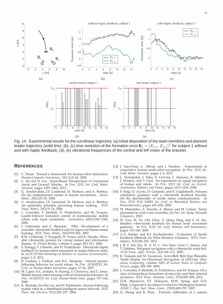
time interval was used to send the haptic signals tothe vibrotactile bracelet. In both the experiments, thefollowers were not initially in formation. They had toreach and keep it during the motion of the humanleader. The followers’ initial conditions with respectto the leader, and the parameters used in the tests arereported in Table 2. The value of V0 was determinedfrom the maximal translational velocity of the PioneerP3AT robot. The minimal non-zero intensity changebetween two consecutive signals was set to ±30% ofthe signal (cf. Sect. 4.3). The above parameters havebeen chosen in order to maintain the person insidethe FOV of the camera at all times. The first followerplays the role of gateway robot (cf. Sect. 4.2). In allthe experiments, the subjects were asked to reachpredefined checkpoints on a given trajectory, but noinstructions were given about their linear and/orangular velocities. All subjects tried once without andonce with haptic feedback. In Figs. 13-14, we reportthe results relative to follower R1 (in fact, the tworobots exhibited very similar behaviors) and subject 1(which is representative of our group of 14 people)for the linear and curvilinear trajectory, respectively.As far as the linear trajectory is concerned, if thehaptic feedback is not provided and the leader doesnot satisfy the linear velocity constraint, the followersare unable to compensate for the initial formationerror (see Fig. 13(b)). On the contrary, by using thevibrotactile bracelet, the user was able to easily adjusther/his velocities according to the provided feedback,and thus reach and keep the desired formation (seeFig. 13(c)). The corresponding vibrational frequencyof the central motor is reported in Fig. 13(d).In the second experiment the user had to satisfyconstraints on both the linear and angular velocities.Again, the haptic feedback was crucial for reducingthe formation error (see Figs. 14(b)-(c)). Figs. 14(d)-(e)report the vibrational frequencies of the central andleft motors. Fig. 15 reports the mean and standarddeviation of the Euclidean norm of the formation errorE1 (obtained by averaging the errors over each timestep along the entire trajectory, and over all the 14 sub-jects) for both the linear and curvilinear trajectories.As it is evident from the figure, the haptic feedback

12
0 2 4 6 8 10
−2
0
2
4
6
8
10
x [m]
y[m
]
R2 R1
R0
(a)
0 1 2 3 4 5 6 7 8 9
−1
−0.5
0
0.5
1
1.5
time [s]
Fo
rmat
ion
erro
r[m
]
without haptic feedback, subject 1
E1,y
E1,x
(b)
0 1 2 3 4 5 6 7 8 9 10 11 12 13 14
−1
−0.5
0
0.5
time [s]
Fo
rmat
ion
erro
r[m
]
with haptic feedback, subject 1
E1,y
E1,x
(c)
0 1 2 3 4 5 6 7 8 9 10 11 12 13 140
central motor, subject 1
time [s]
fM
fm[H
z]
(d)
Fig. 13. Experimental results for the linear trajectory. (a) Initial disposition of the team members and plannedleader trajectory (solid line); (b), (c) time evolution of the formation error E1 = (E1,x, E1,y)
T for subject 1 withoutand with haptic feedback; (d) vibrational frequency of the central motor of the bracelet.
plays a fundamental role in keeping the formationerror small. The users’ response at the end of theexperiments was positive. In fact, according to ourquestionnaire, the mean value of the answers to thequestions about the perceived comfort was 5.6, whileit was 6.3 for the questions about the informativenessof the system.
0
0.5
1
1.5
2
[m]
linear trajectory curvilinear trajectory
without haptic
feedback
with haptic
feedback
Fig. 15. Mean and standard deviation of ‖E1‖ for boththe linear and curvilinear trajectories. The values areobtained by averaging the errors over each time stepalong the entire trajectory, and over all the 14 subjects.
6 CONCLUSIONS AND FUTURE WORK
In this paper we have presented a new formation con-trol setup consisting of a human leader and multiplefollower robots equipped with RGB-D sensors. Vibro-tactile feedback provided by haptic bracelets is usedto guide the human along trajectories that are feasiblefor the leader-follower formation. The effectivenessof the proposed designs has been demonstrated vianumerical simulations and real-world experiments.
In future works, we aim at exploring alternativesolutions for the generation of the vibrotactile feed-back in order to make the system more reactive andinformative to the user. We also plan to extend ourresults to teams including multiple humans and het-erogeneous robots.
ACKNOWLEDGEMENTS
The research leading to these results has receivedfunding from the European Union Seventh Frame-work Programme FP7/2007-2013 under grant agree-ment n. 601165 of the project “WEARHAP - WEAR-able HAPtics for humans and robots” and under grantagreement n. 288917 of the project “DALi - Devicesfor Assisted Living”. The authors are grateful to C.Pacchierotti and L. Meli for useful discussions onthe design of the psychophysical experiments, and toM. Aggravi for his support in the preparation of theexperimental setup.
13
0 2 4 6 8 10
−2
0
2
4
6
8
10
x [m]
y[m
]
R1R2
R0
(a)
0 2 4 6 8 10 12 14
−0.5
0
0.5
1
1.5
2
time [s]F
orm
atio
ner
ror
[m]
without haptic feedback, subject 1
E1,y
E1,x
(b)
0 2 4 6 8 10 12 14 16 18
0
0.5
1
1.5
time [s]
Fo
rmat
ion
erro
r[m
]
with haptic feedback, subject 1
E1,y
E1,x
(c)
0 2 4 6 8 10 12 14 16 180
central motor, subject 1
time [s]
fM
fm
[Hz]
(d)
0 2 4 6 8 10 12 14 16 180
left motor, subject 1
time [s]
fM
fm
[Hz]
(e)
Fig. 14. Experimental results for the curvilinear trajectory. (a) Initial disposition of the team members and plannedleader trajectory (solid line); (b), (c) time evolution of the formation error E1 = (E1,x, E1,y)
T for subject 1 withoutand with haptic feedback; (d), (e) vibrational frequencies of the central and left motor of the bracelet.
REFERENCES
[1] S. Thrun. Toward a framework for human-robot interaction.Human-Computer Interaction, 19(1-2):9–24, 2004.
[2] C. Ha and D. Lee. Vision-Based Teleoperation of UnmannedAerial and Ground Vehicles. In Proc. IEEE Int. Conf. Robot.Automat, pages 1457–1462, 2013.
[3] G. Arechavaleta, J.P. Laumond, H. Hicheur, and A. Berthoz.On the nonholonomic nature of human locomotion. Auton.Robot., 25(1):25–35, 2008.
[4] G. Arechavaleta, J.P. Laumond, H. Hicheur, and A. Berthoz.An optimality principle governing human walking. IEEETrans. Robot., 24(1):5–14, 2008.
[5] L. Consolini, F. Morbidi, D. Prattichizzo, and M. Tosques.Leader-follower formation control of nonholonomic mobilerobots with input constraints. Automatica, 44(5):1343–1349,2008.
[6] J. Lieberman and C. Breazeal. TIKL: Development of awearable vibrotactile feedback suit for improved human motorlearning. IEEE Trans. Robot., 23(5):919–926, 2007.
[7] R.W. Lindeman, Y. Yanagida, H. Noma, and K. Hosaka. Wear-able vibrotactile systems for virtual contact and informationdisplay. In Virtual Reality, volume 9, pages 203–213. 2006.
[8] S. Scheggi, F. Chinello, and D. Prattichizzo. Vibrotactile hapticfeedback for human-robot interaction in leader-follower tasks.In ACM PETRA Workshop on Robotics in Assistive Environments,pages 1–4, 2012.
[9] R. Gockley, J. Forlizzi, and R.G. Simmons. Natural person-following behavior for social robots. In Proc. ACM/IEEE Int.Conf. on Human-Robot Interaction, pages 17–24, 2007.
[10] M. Loper, O.C. Jenkins, N. Koenig, S. Chernova, and C. Jones.Mobile human-robot teaming with environmental tolerance. InProc. ACM/IEEE Int. Conf. Human-Robot Inter., pages 157–164,2008.
[11] K. Morioka, Joo-Ho Lee, and H. Hashimoto. Human-followingmobile robot in a distributed intelligent sensor network. IEEETrans. Ind. Electron, 51(1):229–237, 2004.
[12] J. Saez-Pons, L. Alboul, and J. Penders. Experiments incooperative human multi-robot navigation. In Proc. IEEE Int.Conf. Robot. Automat, pages 1–4, 2011.
[13] L. Nomdedeu, J. Sales, E. Cervera, J. Alemany, R. Sebastia,J. Penders, and V. Gazi. An experiment on squad navigationof human and robots. In Proc. IEEE Int. Conf. on Control,Automation, Robotics and Vision, pages 1212–1218, 2008.
[14] F. Sergi, D. Accoto, D. Campolo, and E. Guglielmelli. Forearmorientation guidance with a vibrotactile feedback bracelet:On the directionality of tactile motor communication. InProc. IEEE RAS EMBS Int. Conf. on Biomedical Robotics andBiomechatronics, pages 433–438, 2008.
[15] M. Matscheko, A. Ferscha, A. Riener, and M. Lehner. Tactorplacement in wrist worn wearables. In Proc. Int. Symp. WearableComputers, 2010.
[16] W. Guo, W. Ni, I-M. Chen, Z. Qiang Ding, and S. H. Yeo.Intuitive vibro-tactile feedback for human body movementguidance. In Proc. IEEE Int. Conf. Robotics and Biomimetics,pages 135–140, 2009.
[17] A.A. Stanley and K.J. Kuchenbecker. Evaluation of TactileFeedback Methods for Wrist Rotation Guidance. IEEE Trans.Haptics, 5(3):240–251, 2012.
[18] J. B. F. Van Erp, H. A. H. C. Van Veen, Chris C. Jansen, andT. Dobbins. Waypoint navigation with a vibrotactile waist belt.ACM Trans. Appl. Percept., 2(2):106–117, 2005.
[19] K. Tsukada and M. Yasumura. ActiveBelt: Belt-Type WearableTactile Display for Directional Navigation. In UbiComp: Ubiq-uitous Computing, volume 3205 of Lecture Notes in ComputerScience, pages 384–399. 2004.
[20] L. Consolini, F. Morbidi, D. Prattichizzo, and M. Tosques. On aclass of hierarchical formations of unicycles and their internaldynamics. IEEE Trans. Automat. Contr., 57(4):845–859, 2012.
[21] D.M. Stipanovic, P.F. Hokayem, M.W. Spong, and D.D.Siljak. Cooperative Avoidance Control for Multiagent Systems.ASME J. Dyn. Syst. Meas. Contr., 129(5):699–707, 2007.
[22] Q. Zhang and R. Pless. Extrinsic calibration of a camera

14
and laser range finder (improves camera calibration). In Proc.IEEE/RSJ Int. Conf. Intel. Robots Syst., pages 2301–2306, 2004.
[23] F. Gemperle, T. Hirsch, A. Goode, J. Pearce, D. Siewiorek, andA. Smailigic. Wearable vibro-tactile display, 2003. CarnegieMellon University.
[24] L.A. Jones and S.J. Lederman. Human hand function. OxfordUniversity Press, 2006.
[25] I. Karuei, K. E. MacLean, Z. Foley-Fisher, R. MacKenzie,S. Koch, and M. El-Zohairy. Detecting vibrations across thebody in mobile contexts. In Proc. Int. Conf. on Human Factorsin Computing Systems, pages 3267–3276, 2011.
[26] L. J. Post, I. C. Zompa, and C. E. Chapman. Perception ofvibrotactile stimuli during motor activity in human subjects.Exp. Brain Res., 100:107–120, 1994.
[27] S. Weinstein. Intensive and extensive aspects of tactile sensi-tivity as a function of body part, sex, and laterality. In The skinsenses, pages 195–218. Erlbaum, 1968.
[28] R. S. Johansson. Tactile sensibility in the human hand: re-ceptive field characteristics of mechanoreceptive units in theglabrous skin. The Journal of Physiology, 281(1), 1978.
[29] A. Riener. Sensor-actuator supported implicit interaction indriver assistance systems. In S. Holldobler et al., editor,Ausgezeichnete Informatikdissertationen 2009, volume 10, pages221–230. 2010.
[30] S. Schatzle, T. Ende, T. Wusthoff, and C. Preusche. Vibrotac:An ergonomic and versatile usable vibrotactile feedback de-vice. In Proc. IEEE Int. Symp. on Robot and Human InteractiveCommunication, pages 670–675, 2010.
[31] I.M. Vogels, A.M. Kappers, and J.J. Koenderink. Hapticaftereffect of curved surfaces. Perception, 25(1):109–119, 1996.
[32] M. J. Griffin. Handbook of human vibration. Elsevier, 1996.[33] R.W. Cholewiak and A.A. Collins. Sensory and Physiological
Bases of Touch. In M.A. Heller and W. Schiff, editors, ThePsychology of Touch, chapter 2, pages 23–60. Erlbaum, 1991.
[34] T. N. Cornsweet. The staircase-method in psychophysics. Am.J. Psychol., 75(3):485–491, 1962.
[35] R. G. Miller. Beyond ANOVA: basics of applied statistics. Chap-man & Hall, 1997.
[36] R. B. Rusu and S. Cousins. 3D is here: Point Cloud Library(PCL). In Proc. IEEE Int. Conf. Robot. Automat, pages 1–4, 2011.
Stefano Scheggi (S’09 - M’12) received theM.S. degree and Ph.D. degree in InformationEngineering from the University of Siena,Italy, in 2007 and 2012, respectively. Hewas a Visiting Scholar at the Department ofComputer Science, George Mason Univer-sity, Fairfax, USA, for six months in 2011,under the supervision of Prof. Jana Kosecka.From September 2012, he holds a postdoc-toral position at the University of Siena, Italy.His research interests include computer vi-
sion, visual servoing, mobile robotics, haptics and augmented/virtualreality.
Fabio Morbidi (S’07 - A’09 - M’12) receivedthe M.S. degree in Information Engineeringand Ph.D. degree in Robotics and Automa-tion from the University of Siena, Italy, in2005 and 2009, respectively. He was a Vis-iting Scholar at the Center for Control, Dy-namical Systems and Computation (CCDC),University of California, Santa Barbara, USA,for six months in 2007-2008. He held post-doctoral positions at the University of Siena,Northwestern University, USA, and Univer-
sity of Texas at Arlington, USA. Since November 2012, he has beenwith the Networked Controlled System (NeCS) team, Inria GrenobleRhone-Alpes, France. His research interests include multi-agentsystems, distributed control, robot vision and road traffic estimation.
Domenico Prattichizzo (S’93 - M’95) re-ceived the M.S. degree in Electronics En-gineering and the Ph.D. degree in Roboticsand Automation from the University of Pisain 1991 and 1995, respectively. Since 2002Associate Professor of Robotics at the Uni-versity of Siena. Since 2009 Scientific Con-sultant at Istituto Italiano di Tecnoloogia, Italy.In 1994, Visiting Scientist at the MIT AI Lab.Guest Co-Editor of Special Issue “Roboticsand Neuroscience” of the Brain Research
Bulletin (2008). Co-author of the “Grasping” chapter of “Handbookof Robotics” Springer, 2008, awarded with two PROSE Awardspresented by the American Association of Publishers. Since 2014,Associate Editor of Frontiers of Biomedical Robotics. From 2007 to2013 Associate Editor in Chief of the IEEE Trans. on Haptics. From2003 to 2007, Associate Editor of the IEEE Trans on Robotics andIEEE Trans. on Control Systems Technologies. From 2013 Chair ofthe IEEE RAS Early Carreer Awards Evaluation Panel. Vice-chairfor Special Issues of the IEEE Technical Committee on Haptics(2006-2010). Chair of the Italian Chapter of the IEEE RAS (2006-2010), awarded with the IEEE 2009 Chapter of the Year Award. Co-editor of two books by STAR, Springer Tracks in Advanced Robotics,Springer (2003, 2005). Research interests are in haptics, grasping,visual servoing, mobile robotics and geometric control. Author ofmore than 200 papers in those fields. Leader of a research unitin four EU projects: ROBOCAST, THE, ACTIVE, DALI. Coordinatorof the EU ECHORD-EXPERIMENT HANDS.DVI. From March 2013Coordinator of the IP collaborative project ”WEARable HAPtics forHumans and Robots” (WEARHAP).