Human Motion Analysis for Creating Immersive Experience
85
Human Motion Analysis for Creating Immersive Experience FARID ABEDAN KONDORI Digital Media Lab Department of Applied Physics and Electronics Umeå University Umeå, Sweden 2012
Transcript of Human Motion Analysis for Creating Immersive Experience

Human Motion Analysisfor Creating Immersive Experience
FARID ABEDAN KONDORI
Digital Media LabDepartment of Applied Physics and Electronics
Umeå UniversityUmeå, Sweden 2012

Human Motion Analysisfor Creating Immersive ExperienceFarid Abedan Kondori
Licentiate ThesisDigital Media LabDepartment of Applied Physics and ElectronicsUmeå UniversitySE-901 87 Umeå, SwedenPhone: +46 (0)90-786 67 15
ISSN 1652-6295:15ISBN 978-91-7459-416-4
Copyright c© Farid Abedan Kondori, 2012.
Author e-mail: [email protected] in LATEX by Farid Abedan KondoriPrinted by Print & Media, Umeå University, Umeå, Sweden 2012

Human Motion Analysisfor Creating Immersive Experience
Farid Abedan KondoriDepartment of Applied Physics and Electronics, Umeå University
ABSTRACTFrom an early age, people display the ability to quickly and effortlessly interpretthe orientation and movement of human body parts, thereby allowing one to inferthe intentions of others who are nearby and to comprehend an important nonverbalform of communication. The ease with which one accomplishes this task beliesthe difficulty of a problem that has challenged computational systems for decades,human motion analysis.
Technological developments over years have resulted into many systems formeasuring body segment positions and angles between segments. In these sys-tems human body is typically considered as a system of rigid links connected byjoints. The motion is estimated by the use of measurements from mechanical, op-tical, magnetic, or inertial trackers. Among all kinds of sensors, optical sensingencompasses a large and varying collection of technologies.
In a computer vision context, human motion analysis is a topic that studiesmethods and applications in which two or more consecutive images from an imagesequences, e.g. captured by a video camera, are processed to produce informationbased on the apparent human body motion in the images.
Many different disciplines employ motion analysis systems to capture move-ment and posture of human body for applications such as medical diagnostics,virtual reality, human-computer interaction etc.
This thesis gives an insight into the state of the art human motion analysissystems, and provides new methods for capturing human motion.
Keywords: Human Motion Analysis, Active Motion Capture, Passive Motion estimation,3D Head Pose Estimation, Hand Gesture Recognition, Hand Gesture Motion Estimation,Human Computer Interaction, Immersive Interaction.

ii

Preface
This thesis is based on the following publications:
I. Farid Abedan Kondori, Li Liu, “3D Active Human Motion Esti-mation for Biomedical Applications,” accepted in World Congress onMedical Physics and Biomedical Engineering (WC2012), Beijing, China,26-31 May 2012.
II. Farid Abedan Kondori, Shahrouz Yousefi, Haibo Li, Samuel Son-ning, Sabina Sonning, “3D Head Pose Estimation Using the Kinect,” inIEEE International Conference on Wireless Communications and Sig-nal Processing (WCSP2011), Nanjing, China, 9-11 November 2011,pp.1-4.
III. Shahrouz Yousefi, Farid Abedan Kondori, Haibo Li, “Tracking Fin-gers in 3D Space for Mobile Interaction,” In Proceeding of The 20thInternational Conference on Pattern Recognition (ICPR), The SecondInternational Workshop on Mobile Multimedia Processing (WMMP),Istanbul, Turkey, August 2010, pp.72-79.
IV. Farid Abedan Kondori, Shahrouz Yousefi, Haibo Li, “Real 3D In-teraction Behind Mobile Phones for Augmented Environments,” inIEEE International Conference on Multimedia and Expo (ICME2011),Barcelona, Spain, 11-15 July 2011, pp.1-6.
Other publications are listed here:
. Farid Abedan Kondori, Shahrouz Yousefi, Haibo Li, “Gesture Tracking for3D Interaction in Augmented Environments,” In Proceeding of The SwedishSymposium on Image Analysis (SSBA2011), Linköping, Sweden, 17-18 March2011.
. Farid Abedan Kondori, Shahrouz Yousefi, “Smart Baggage in Aviation,”in IEEE International Conference on Internet of Things and International
iii

iv PREFACE
Conference on Cyber, Physical and Social Computing, Dalian, China, Octo-ber 2011, pp.620-623.
. Shahrouz Yousefi, Farid Abedan Kondori, Haibo Li, “Robust correction of3D geo-metadata in photo collections by forming a photo grid,” in IEEE In-ternational Conference on Wireless Communications and Signal Processing(WCSP2011), Nanjing, China, 9-11 November 2011, pp.1-5.
. Shahrouz Yousefi, Farid Abedan Kondori, Haibo Li, “3D gestural interac-tion for stereoscopic visualization on mobile devices,” in Proceedings of the14th international conference on Computer analysis of images and patterns(CAIP’11), Seville, Spain, 29-31 August 2011, pp.555-562.
. Shahrouz Yousefi, Farid Abedan Kondori, Haibo Li, “3D visualization ofsingle images using patch level depth,” in Proceedings of the InternationalConference on Signal Processing and Multimedia Applications (SIGMAP2011),Seville, Spain, 18-21 July 2011, pp.61-66.
. Shahrouz Yousefi, Farid Abedan Kondori, Haibo Li, “Stereoscopic visu-alization of monocular images in photo collections,” in IEEE InternationalConference on Wireless Communications and Signal Processing (WCSP2011),Nanjing, China, 9-11 November 2011, pp.1-5.
. Shahrouz Yousefi, Farid Abedan Kondori, Haibo Li, “3D Visualizationof Monocular Images in Photo Collections,” In Proceeding of The SwedishSymposium on Image Analysis (SSBA2011), Linköping, Sweden, 17-18 March2011.
Under-review journal articles
. Shahrouz Yousefi, Farid Abedan Kondori, Haibo Li, “ExperiencingReal 3D Gestural Interaction with Mobile Devices,” submitted to ThePattern Recognition Letters (PRLetters), December 2011.
. Shahrouz Yousefi, Farid Abedan Kondori, Haibo Li, “Gesture Track-ing For Real 3D Interaction Behind Mobile Devices,” submitted toThe International Journal of Pattern Recognition and Artificial Intel-ligence (IJPRAI), 2011.

Acknowledgments
I am grateful to the following people who have directly or indirectly contributed tothe work in this thesis and deserve acknowledgment.
First of all I would like to thank my supervisor Prof. Haibo Li for not onlythe opportunities provided and all the hard work, but also for the positive envi-ronment he creates in our research group. I am truly indebted and thankful forthe valuable guidance from him in the research world and for all the support andencouragement.
I am grateful to my advisors, Dr. Adi Anani and Dr. Li Liu for inspiringdiscussions, practical suggestions, and providing the financial support.
I would also like to thank my best friend, and my best colleague, ShahrouzYousefi with whom I have spent a great deal of time since 2001. Without hiscontributions I would not have been able to pursue my research.
Special gratitude goes to my friends and colleagues, Zeynab Kolahi, Jean-Paul Kouma, Shafiq Ur Rehman, Alaa Halawani, and Ulrik Söderström for theirinspiration and support.
Thanks to all the staff at the Department of Applied Physics and Electronics(TFE) for creating an enjoyable and interesting working environment. I expressmy warm thanks to Annemaj Nilsson and Mona-Lisa Gunnarsson who have alwayshelped me.
Special thanks also to Annika Bindler, who gave a great deal of assistance forcorrecting the writing errors in the final revision of this thesis.
Finally but most importantly, I owe sincere and earnest thankfulness to myparents and my brothers, without whom none of this would be possible, for all thelove and support they provide.
Thank you all.
Farid Abedan KondoriUmeå, April 2012
v

vi ACKNOWLEDGMENTS

Contents
Abstract i
Preface iii
Acknowledgments v
I INTRODUCTION 1
1 Introduction 31.1 Motivation . . . . . . . . . . . . . . . . . . . . . . . . . . . . . . 31.2 State of the art . . . . . . . . . . . . . . . . . . . . . . . . . . . . 41.3 New areas, new possibilities . . . . . . . . . . . . . . . . . . . . 51.4 Research goal . . . . . . . . . . . . . . . . . . . . . . . . . . . . 81.5 Potential impact . . . . . . . . . . . . . . . . . . . . . . . . . . . 81.6 Thesis outline . . . . . . . . . . . . . . . . . . . . . . . . . . . . 9
II DEVELOPING MOTION CAPTURE TECHNIQUES 11
2 Head Pose Estimation 132.1 Introduction . . . . . . . . . . . . . . . . . . . . . . . . . . . . . 132.2 Related work . . . . . . . . . . . . . . . . . . . . . . . . . . . . 142.3 Active & Passive motion capture . . . . . . . . . . . . . . . . . . 152.4 Active head motion estimation . . . . . . . . . . . . . . . . . . . 16
2.4.1 Head pose estimation . . . . . . . . . . . . . . . . . . . . 172.5 Passive head motion estimation . . . . . . . . . . . . . . . . . . . 19
2.5.1 3D linear & 2D nonlinear methods . . . . . . . . . . . . . 192.5.2 Kinect . . . . . . . . . . . . . . . . . . . . . . . . . . . . 212.5.3 System description . . . . . . . . . . . . . . . . . . . . . 212.5.4 Multiple head detection and tracking . . . . . . . . . . . . 22
vii

viii CONTENTS
2.5.5 3D head pose estimation . . . . . . . . . . . . . . . . . . 22
3 Hand Motion Estimation 273.1 Introduction . . . . . . . . . . . . . . . . . . . . . . . . . . . . . 273.2 Previous implementation . . . . . . . . . . . . . . . . . . . . . . 283.3 Vision-based gesture detection & tracking . . . . . . . . . . . . . 30
3.3.1 Gesture detection . . . . . . . . . . . . . . . . . . . . . . 303.4 Gesture motion estimation . . . . . . . . . . . . . . . . . . . . . 31
III EVALUATING MOTION CAPTURE SYSTEMS 33
4 Evaluation of Head Motion Estimation Systems 354.1 Introduction . . . . . . . . . . . . . . . . . . . . . . . . . . . . . 354.2 Design criteria . . . . . . . . . . . . . . . . . . . . . . . . . . . . 354.3 System evaluation . . . . . . . . . . . . . . . . . . . . . . . . . . 36
4.3.1 Passive head motion estimation . . . . . . . . . . . . . . 364.3.2 Active head motion estimation . . . . . . . . . . . . . . . 38
4.4 Conclusion . . . . . . . . . . . . . . . . . . . . . . . . . . . . . 40
5 Evaluation of Hand Gesture Recognition System 435.1 Introduction . . . . . . . . . . . . . . . . . . . . . . . . . . . . . 435.2 Design criteria . . . . . . . . . . . . . . . . . . . . . . . . . . . . 435.3 System Evaluation . . . . . . . . . . . . . . . . . . . . . . . . . 44
IV APPLICATION DOMAINS 47
6 Applications 496.1 Application areas . . . . . . . . . . . . . . . . . . . . . . . . . . 49
V CONTRIBUTIONS, DISCUSSIONS, AND FUTURE DIREC-TIONS 53
7 Outline and Summary of Contributions 557.1 Summary of contributed papers . . . . . . . . . . . . . . . . . . . 557.2 Summary of contributions . . . . . . . . . . . . . . . . . . . . . 57
8 Concluding Remarks & Future Directions 598.1 Conclusions . . . . . . . . . . . . . . . . . . . . . . . . . . . . . 598.2 Future directions . . . . . . . . . . . . . . . . . . . . . . . . . . 60

CONTENTS ix
Bibliography 62

x CONTENTS

List of Figures
1.1 Marker-based human motion analysis. Left: Schematic of theset-up with six cameras. Right: Subject equipped with reflectivemarkers that are detected and tracked by cameras to estimate themotion [1]. . . . . . . . . . . . . . . . . . . . . . . . . . . . . . 5
1.2 Emergence of new visual sensors, advance computer vision algo-rithms, and applications that require immersive interactions showus the future directions to develop new human motion analysistechniques. . . . . . . . . . . . . . . . . . . . . . . . . . . . . . 6
1.3 Moving from 2D touch screen interaction space towards 3D spacebehind smartphones, new natural user interfaces for mobile appli-cations are designed. Users can manipulate the virtual object onthe mobile screen using their hand gestures [2]. . . . . . . . . . . 8
2.1 Top view of a head and a fixed camera. The head turns with angleθ causing a change in the resulted image. The amount of changedepends on the camera location (A or B) [3]. . . . . . . . . . . . 15
2.2 Active motion tracking system. . . . . . . . . . . . . . . . . . . 172.3 Top, two consecutive frames. Bottom, point correspondences be-
tween them [3]. . . . . . . . . . . . . . . . . . . . . . . . . . . 182.4 Microsoft Kinect: (A) laser projector, (B) RGB camera, (C),
monochrome CMOS camera [4]. . . . . . . . . . . . . . . . . . 202.5 Passive head pose estimation system [4]. . . . . . . . . . . . . . 212.6 Head detection scheme [4]. . . . . . . . . . . . . . . . . . . . . 232.7 Head localization [4]. . . . . . . . . . . . . . . . . . . . . . . . 24
3.1 Taxonomy of hand gestures. . . . . . . . . . . . . . . . . . . . . 273.2 3D vision-based human mobile interaction system [2]. . . . . . . 293.3 Rotational Symmetries. Linear, curvature, and circular patterns [2]. 303.4 (a) User hand gesture, (b) Localized gesture [2]. . . . . . . . . . 31
xi

xii LIST OF FIGURES
3.5 Feature matching in two consecutive frames where 54 point cor-respondences are detected [2]. . . . . . . . . . . . . . . . . . . . 32
4.1 Experimental results. The 3D head motion parameters are esti-mated to update the position and orientation of the 3D model.First row is the initial position. Next three rows show the rota-tion around X, Y, and Z axes respectively. The last three rowsillustrate the translation in X, Y, and Z [4]. . . . . . . . . . . . . 37
4.2 Electronic measuring device. a) The setup for Z-axis, b) for X-axis, and c) for Y-axis [3]. . . . . . . . . . . . . . . . . . . . . . 38
4.3 Active motion tracking demo. As the user turns his head, the mo-tion parameters are estimated and used to change the 3D modelon the computer screen [3]. . . . . . . . . . . . . . . . . . . . . 39
5.1 (a) System performance in gesture tracking. (b) Error of thetracking in a sequence of images [5]. . . . . . . . . . . . . . . . 44
5.2 Relative rotation and translation between image sequences. (a)The teapot should rotate in the direction specified by the arrowwhile the user gesture rotates in the same direction. (b) Consecu-tive frames (top), feature matching between two images (middle),and applying user gesture motion to the teapot (bottom) [2]. . . . 45

Part I
INTRODUCTION


Chapter 1
Introduction
1.1 Motivation
The study of human motion dates back to 1870s when Muybridge [6] started hiswork. Since then, the field of human motion analysis has grown in many direc-tions. However, research and results that involve the recovery of human motion isstill far from being satisfactory. The science of human motion analysis is fascinat-ing because of its highly interdisciplinary nature and wide range of applications.The modeling, tracking, and understanding of human motion has gained more andmore attention particularly in the last decade with the emergence of applicationsin sports sciences, human-machine interaction, medicine, biomechanics, entertain-ment, surveillance, etc.
Human motion analysis plays an essential role in human computer interaction(HCI), for bridging the information gap between humans and computers. Cur-rently, due to the large influx of computers in our daily lives, HCI has becomecrucially important. Conventionally, keyboard and mouse have played the mainrole in HCI. However, with the rapid progress of computing, communication, anddisplay technologies, such interfaces may become a bottleneck in applications thatrely on heavy interaction of users with machines because of the unnaturalness ofthe interaction. Thus, researchers have recently attempted to eliminate this HCIbottleneck by developing more natural ways of interaction. With this motivation,human motion estimation and human gesture recognition have been topics of re-search for decades.
Additionally, tracking human body parts and recovering the underlying 3Dhuman body structure are critically valuable for medical diagnostics systems, en-tertainment industry, and analysis of athletic performance. The capability to au-tomatically observe human activities in security-sensitive areas such as airports,borders, and banks is of great interest to the security services as well.
3

4 CHAPTER 1. INTRODUCTION
1.2 State of the art
Most of the existing human motion tracking and analysis systems can be classifiedinto two categories: position sensing systems and vision-based tracking systems.
• Position sensing systems
In the position sensing paradigm, a set of sensors is mounted on the user bodyin order to collect motion information and detect changes in body position. Sev-eral different types of sensors have been considered. Inertial and magnetic sensorsare examples of widely used sensor types. Well-known types of inertial sensorsare accelerometers and gyroscopes. An accelerometer is a device used to measurephysical acceleration experienced by the user [7] [8]. It is sensitive to vibrationalartifacts [9]. Another shortcoming of the accelerometers is the lack of informa-tion about the rotation around the global Z-axis [10]. Hence, Gyroscopes, whichare capable of measuring angular velocity, can be used in combination with ac-celerometers in order to give a complete description of orientation [11]. Although,the major disadvantage of the inertial sensors is the drift problem. New positionsare calculated based on previous positions, meaning that any error in the measure-ments will be accumulated over time.
Magnetic sensors can be utilized for human motion estimation as well. The useof the magnetic sensors is reported in several works [12] [13]. A magnetic sensor,or magnetometer, is a device that is used to measure the strength and directionof a magnetic field. The performance of the magnetic sensors is affected by theavailability of ferromagnetic materials in the surrounding environment [14].
• Vision-based systems
Vision-based motion capture systems rely on a camera as an optical sensor. Twodifferent types can be identified: Marker-based and marker-less systems.
The idea behind marker-based systems is to place some type of visual identi-fiers on the joints to be tracked. Stereo cameras are then used to detect these mark-ers and estimate the motion between consecutive frames. One example of such asystem is illustrated in Fig. 1.1. These systems are accurate and have been usedsuccessfully in biomedical applications [15] [16] [17]. Although, many difficultiesare associated with such a configuration. For instance, scale changes (distance ofthe user to the camera) and light conditions will seriously affect the performance.Additionally marker-based systems suffer from occlusion (line of sight) problemswhenever a required light path is blocked. Interference from other light sourcesor reflections may also be a problem, which can result in so-called ghost markers.The most important limitation for such systems is a need to use special markers to

1.3. NEW AREAS, NEW POSSIBILITIES 5
Figure 1.1: Marker-based human motion analysis. Left: Schematic of the set-up with sixcameras. Right: Subject equipped with reflective markers that are detected and tracked bycameras to estimate the motion [1].
attach to the human body; furthermore, human motion can only be analyzed in apredefined area covered by fixed, expensive cameras.
Marker-less systems rely only on cameras and try to employ computer visiontechniques to estimate the motion. The use of cheap cameras is possible in suchsystems [18] [19]. However, the markers removal comes with the price of compli-cating the estimation process of 3D non-rigid human motion. Developing marker-less motion capture systems is still an on-going research topic in computer vision,and only partial success in real situations has been achieved [20]. Several problemssuch as cluttered scene, human occlusion, scale variation and illumination can de-grade the system performance. Nevertheless, the most essential drawback reportedin these systems is the resolution problem. Since human body motion results inchanges in a small region of the scene, small movements cannot be detected.
1.3 New areas, new possibilities
In addition to the limitations of the previous implementations, it needs taken intoaccount that with the recent progress in technology and computer science, thereare new factors that offer new possibilities to research communities for developing

6 CHAPTER 1. INTRODUCTION
Figure 1.2: Emergence of new visual sensors, advance computer vision algorithms, andapplications that require immersive interactions show us the future directions to developnew human motion analysis techniques.
new human motion analysis theories. Three main areas that provide us with newopportunities to develop new motion analysis techniques are new visual sensors,fast and robust computer vision algorithms, and emergence of new applications(Fig. 1.2).
• Sensor-driven methodologies
New visual sensors have opened a new angle for researchers recently. New highresolution cameras are becoming smaller, and therefore, can be conveniently mountedonto a human body to analyze human activities. They are also capable of recordinghuman daily life activities for future analysis. Thence, one can ask the question:why not use small, low-cost cameras as optical trackers to estimate human motion?
Another type of inexpensive visual sensors that can be employed to analyzehuman movements is new depth sensors. Kinect is one of those new depth sen-sors [21]. It interprets 3D scene information from a continuously-projected in-frared structured light. Kinect provides a robust solution to infer 3D informationof the scene and has a big potential to be used in human motion analysis systems.Using the knowledge about 3D structure of the scene, it is possible to directly es-timate human motion. Chapter 2 presents an in-depth discussion concerning thisarea.
• Algorithm-driven methodologies
During the last decade, massive contributions and publications in the computervision field have resulted into robust algorithms that have high potential to be uti-lized in human motion analysis systems. In recent years, scale-invariant feature

1.3. NEW AREAS, NEW POSSIBILITIES 7
transform (SIFT) [22] has become a strong tool for researchers to overcome thetraditional limitations in many areas in computer vision fields, such as object de-tection, classification, and motion estimation. However, since SIFT is computa-tionally expensive, it was impossible to apply it to real-time applications. Fortu-nately, today, with integrating graphical processing units (GPUs) in computers andmobile phones, it is possible to efficiently implement this robust computer visionalgorithm into computers and mobile applications.
• Application-driven methodologies
New possibilities for creating new motion analysis systems have become evenmore apparent with the emergence of smart phones, 3D TVs, and intelligent en-vironments (IEs). Almost all new smart phones are equipped with powerful pro-cessors, as well as high resolution cameras. Thus, they provide the opportunityto employ computer vision algorithms to develop new human mobile interaction(HMI) systems to overcome the limitations of the current HMI systems [2]. New3D TVs and 3D displays can also benefit from human motion estimation. Ba-sically they display offset image frames that are filtered separately to the left andright eye. Estimating viewer’s head motion, the frames can be separately displayedto the viewer’s left and right eye to avoid wearing 3D glasses.
Intelligent environments describe physical environments in which informationand communication technologies and sensor systems disappear as they becomeembedded into physical objects, infrastructures, and the surroundings in which welive, travel, and work [23]. Here, the goal is to allow computers to take part inactivities never previously involved and allow people to interact with computersvia gesture, voice, movement, and context.
Therefore, natural immersive interaction between users and computers is maincharacteristic of such applications. Here the question naturally arises: is there anyinteraction system that can meet users’ demands, and in addition, is easy to learnand use. For a long time, graphical user interfaces (GUIs) have been the dominantplatform for human computer interaction. However, as computing becomes morewidespread and ubiquitous, GUIs will not easily support the range of interactionsnecessary to satisfy users’ needs [24]. In order to accommodate a wider range ofscenarios, tasks, users, and preferences, we need to move toward new interfacesthat are more immersive, natural, intuitive, adaptive, and unobtrusive. With thismotivation, the aim of a new generation of interfaces, Perceptual User Interfaces(PUIs), is to make human-computer interaction more like how people interact witheach other and with the world [24]. Obviously, a detailed analysis of human mo-tions and gestures is critically important to achieve perceptual user interfaces (seeFig. 1.3).

8 CHAPTER 1. INTRODUCTION
Figure 1.3: Moving from 2D touch screen interaction space towards 3D space behindsmartphones, new natural user interfaces for mobile applications are designed. Users canmanipulate the virtual object on the mobile screen using their hand gestures [2].
1.4 Research goal
The aims of this thesis are to develop computer vision theories for:
• Overcoming the limitations inherent in the current motion tracking systems.
• Providing higher motion resolution than the state of the art.
• Enabling the development of wearable human motion tracking and analysissystems.
• Directly recovering 3D human motion parameters from a sequence of rangeimages.
• Creating natural and immersive forms of interaction between humans andtechnology.
1.5 Potential impact
• Biomedical applications. Many people around the world suffer from move-ment disorders. Only in the United States more than 40 million Americanare affected [25]. Based on a research conducted in Germany, there willbe a dramatic increase in the number of people affected by most movementdisorders between 2010 and 2050 [26]. For instance, the number of peo-ple who are diagnosed with Parkinson’s disease will increase up to 92% by

1.6. THESIS OUTLINE 9
2050. Designing accurate human motion analysis systems can be beneficialto diagnose and treat such a disease.
• Entertainment. In 2011 game console manufactures sold approximately200 million game consoles over the world, and this number will increasein the future. As graphical features become more realistic, the users ex-pect more natural means of interaction with game consoles. Hence humangesture recognition will have a long way ahead in this area.
• Natural interaction. Total smartphone sales in 2011 reached 472 millionunits and are estimated to rise to 980 million units in 2015 [27]. It is alsoexpected that the number of tablets sold in 2011 will increase from 54.7million to 79 million units in 2012 [28]. Because PC adoption in emergingmarkets is growing fast, it is estimated that there will be more than twobillion PCs in use by 2015 [29]. These growing numbers reveal the hugeimpact of HMI and HCI in the near future. Developing new techniques toestimate and analyze the human motion will make a breakthrough in thisfield.
1.6 Thesis outline
Proposed techniques for capturing human motion are discussed in depth in Chap-ters 2 and 3. Then in Chapters 4 and 5, design criteria and system evaluationsare demonstrated. Numerous potential applications for human motion analysis arereviewed in Chapter 6. A summary of contributions from the thesis is provided inChapter 7. Finally, concluding remarks and future directions are summarized inChapter 8.

10 CHAPTER 1. INTRODUCTION

Part II
DEVELOPING MOTIONCAPTURE TECHNIQUES


Chapter 2
Head Pose Estimation
2.1 Introduction
Head motion is used to convey rich information in our daily lives. For instance,a person will point his head to indicate who the intended target in a conversationis. In a similar way in a discussion, head direction provides a nonverbal cue to alistener when to switch roles and begin speaking. In addition to the informationresulted from deliberate head gestures, the visual focus of attention can be inferredby monitoring a person’s head. Visual attention is naturally linked with eye gazeestimation, i.e. the ability to estimate the direction and focus of a person’s eye.
Basically, head pose provides a rough indication of gaze that can be estimatedin situations when the eyes are not visible (like low-resolution imagery, or in thepresence of eye-occluding objects like sunglasses). When the eyes are visible,head pose becomes a requirement to accurately predict gaze direction. Knowledgeabout gaze direction can be deployed in various applications such as video con-ferencing and human-computer interfaces. In the context of video compression,robust 3D head pose estimation is substantially helpful tool to remove redundantinformation from video frames, and improve the level of data compression. Fur-thermore, face recognition systems can also benefit from robust and efficient headmotion estimation technique.
In recent years there has been much research effort spent on creating new gen-eration of user interfaces that enable natural, intuitive, and immersive interactionsbetween humans and computers. As a consequence, moving from classical graph-ical user interfaces to natural perceptual user interfaces is undeniable. Therefore,understanding and analyzing the head motion is crucially important for deliveringnatural, unobtrusive and intuitive interactions. For instance, head pose estimationcan enhance human computer interaction to a large extent. Controlling computermouse and responding to pop-up dialog boxes using head movements are only
13

14 CHAPTER 2. HEAD POSE ESTIMATION
some existing examples that demonstrate how head pose estimation can changeHCI systems.
Recall from the previous Chapter, 3D TVs and displays can also deliver in-tuitive and interactive experiences employing head pose estimation techniques.Since the major challenge in these systems is to transmit offset image frames to hu-man eyes, head motion analysis could endow them with the capability to localizeand track the eyes for displaying separate image frames to each eye.
2.2 Related work
3D head pose estimation is a challenging problem in the computer vision fieldowing to pose variations, illumination and complexity of the backgrounds. Con-ventional head pose estimation methods incorporate images taken by cameras asthe input. Appearance template methods use image-based comparison metrics tomatch a new image of a head to a set of exemplars with corresponding pose labelin order to find the most similar view [30] [31]. Some methods use the locationof features such as the eyes, mouth, and nose tip to determine the head pose fromtheir relative configuration [32] [33].
Tracking methods estimate the global pose change of the head from the ob-served movement between video frames [34] [35]. These methods involve extract-ing keypoints in the image, such as scale-invariant feature transform (SIFT) [22]to recover the motion from one frame to another frame. Though, these methodssuffer from illumination changes. Range images, on the contrary, are well knownto be robust against illumination variations in the environment and can be consid-ered as a solution. In addition dealing with multiple users tracking where heads ofdifferent people overlap with each other or are occluded by other objects is still anissue [36] [37] [38].
RGB image based approaches encounter difficulties in retrieving the head.Employing depth information will substantially enhance the head retrieval sinceindividual heads are discriminated from each other due to the knowledge of theircorresponding depths. In the past few years, researchers have focused on usingtime-of-flight range cameras (TOF). They have proposed different algorithms toaddress the problem of pose estimation and human motion capture from range im-ages [39] [40] [41] [42]. Although these methods have acceptable performance,they are limited in the sense that the all six DOF of the head motion cannot berecovered.

2.3. ACTIVE & PASSIVE MOTION CAPTURE 15
Figure 2.1: Top view of a head and a fixed camera. The head turns with angle θ causinga change in the resulted image. The amount of change depends on the camera location (Aor B) [3].
2.3 Active & Passive motion capture
In this section the concepts of active and passive motion capture systems are clar-ified, and a technical comparison between these two methods is presented. Con-ventionally, vision-based human motion tracking systems place the camera in par-ticular point, where the camera can see the user. Thus, the user has to performdesired movements and gestures in the camera’s field of view. We address such aconfiguration as passive motion capture system. However there is another way, wesuggest mounting the camera on the human body and performing motion tracking.Therefore, the subject is not limited to be in the camera’s field of view. We referto this system as active motion capture system. When using the passive config-uration, certain issues must be considered. As mentioned in section 1.2, in somecases there is a need to use special markers to detect and track human body motion.Consequently, the system can fail due to the incorrect marker detection.
Other problems such as cluttered scene, human occlusion, scale variation andillumination can degrade the system performance. Nevertheless, the most essentialdrawback associated with the passive systems is the resolution problem. Humanmotion results in changes in a small region of the scene, the fact that increases theburden of detecting small movements accurately [43]. But, we believe these chal-lenges can easily be resolved employing active motion tracking. Since the camerais mounted on the user body, there is no need to detect special markers to trackuser motion. Instead, stable key points are extracted in the video frames. These

16 CHAPTER 2. HEAD POSE ESTIMATION
points will be tracked in consecutive frames for estimating the human motion. Inthe proposed approach SIFT [22] algorithm is used to detect key points. SIFTfeatures are scale invariant, and highly robust against illumination changes.
In addition, active motion tracking can dramatically enhance the resolutionproblem. Based on the experiments in our lab, mounting the camera on the humanbody can enhance the resolution in the order of 10 times compared to the passivesetup [43]. In order to simplify the idea, consider a simple rotation around y-axisas it is illustrated in Fig. 2.1. This figure shows a top view of an abstract humanhead and a camera. Two possible configurations for human motion tracking arepresented, placing the camera at point A, in front of the user (the passive setup)and mounting the camera on the head at point B (the active setup). As the userturns with angle θ, the horizontal change (∆x) in captured images is calculated forboth setups based on the perspective camera model. Let’s assume θ = 45o, thenfor the passive motion tracking:
∆x1 = fr1√
2r2 − r1(2.1)
and for the active motion tracking:
∆x2 = fr2r2
(2.2)
fr1√
2r2 − r1� f ⇒ ∆x1 � ∆x2 (2.3)
For example, if f = 100, r1 = 15cm, r2 = 80cm, then the change for both caseswill be:
∆x1 =
(0.15√
2 ∗ 0.8− 0.15
)∗ 100 ≈ 15.3 pixels (2.4)
∆x2 = 100 pixels (2.5)
This indicates that motion detection is much easier when mounting the camera onthe head, since the active camera configuration causes changes in the entire imagewhile the passive setup often affects a small region of the image.
2.4 Active head motion estimation
Fig. 2.2 depicts active motion tracking system overview. In this particular scenario,we want to measure user’s head motion. A wearable camera is mounted on the

2.4. ACTIVE HEAD MOTION ESTIMATION 17
Figure 2.2: Active motion tracking system.
user’s ear. It should be realized that the camera can be either used to record theuser’s head movements during daily life activities for offline analysis, or to providelive video frames for online analysis. As he turns his head, the video frames fromthe camera are fed to the system. Then stable interest points in the scene areextracted. These points are tracked in the next frame to find point correspondences.Afterwards, head motion parameters are recovered.
2.4.1 Head pose estimation
In order to analyze and estimate the head motion, stable key points have to bedetected within the entire image. Among different feature detectors, SIFT is se-lected owing to its invariance to image transformation. Next, feature point corre-spondences are found between consecutive frames using pyramidal Lucas-Kanadeoptical flow algorithm [44]. This method is appropriate for fast motion trackingand has a low computational cost which is of our interest in real time applications.Two consecutive frames and corresponding key points are illustrated in Fig. 2.3.After finding point correspondences, a fundamental matrix for each image pair iscomputed using robust iterative RANSAC algorithm [45]. RANSAC algorithm isused to detect and remove the wrong matches and improve the performance. Run-ning RANSAC algorithm, a candidate fundamental matrix is computed based on8-point algorithm [46]. The fundamental matrix F is the 3× 3 matrix that satisfiesthe epipolar constraint
x′Ti Fxi = 0 (2.6)
where xi and x′i are a set of image point correspondences. Each point correspon-
dence provides one linear equation in the entries of F . Due to the fact that F isdefined up to a scale factor, F can be computed from 8 point correspondences [46].If the intrinsic parameters of the cameras are known, as they are in our case, thecameras are said to be calibrated. Then, a new matrix E can be introduced byequation
E = K′TFK (2.7)

18 CHAPTER 2. HEAD POSE ESTIMATION
Figure 2.3: Top, two consecutive frames. Bottom, point correspondences betweenthem [3].
where the matrix E is called the essential matrix, K′
and K are 3 × 3 uppertriangular calibration matrices holding intrinsic parameters of the cameras for twoviews. Once the essential matrix is known, the relative translation and rotationmatrices, t and R can be recovered from it. Let the singular value decompositionof the essential matrix be
E ∼ Udiag(1, 1, 0)V T (2.8)
where U and V are chosen such that det (U) > 0 and det (V ) > 0 (∼ denotesequality up to scale). If we define the matrix D as:
D ≡
0 1 0−1 0 0
0 0 1
Then t ∼ tu ≡
[u13 u23 u33
]T and R is equal to Ra ≡ UDV T or Rb ≡UDTV T . If we assume that the first camera matrix is [I | 0] and t ∈ [0, 1], thereare then 4 possible configurations for second camera matrix: P1 ≡ [Ra | tu],P2 ≡ [Ra | −tu], P3 ≡ [Rb | tu] and P4 ≡ [Rb | −tu]. One of these solutions cor-responds to true configuration. In order to determine the true solution, one point isreconstructed using one of four possible configurations. If the reconstructed pointis in front of both cameras, the solution corresponds to the true configuration [46].Once the right configuration is obtained, the relative head motion between twoconsecutive frames is computed. For instance, in Fig. 2.3 the relative head ro-

2.5. PASSIVE HEAD MOTION ESTIMATION 19
tation between two consecutive images are X = 1.6394, Y = −3.7986, andZ = −0.5870 degree respectively.
2.5 Passive head motion estimation
This section addresses the problem of nonlinearity inherent in conventional 3Dmotion estimation techniques using only 2D RGB images. Then an innovativeapproach is presented based on the range images taken by Kinect to tackle thisissue, which results in a passive head pose estimation method.
2.5.1 3D linear & 2D nonlinear methods
Here the same notations used by Horn [47] are employed to explore the nonlin-earity associated with 2D RGB image-based motion estimation techniques. First,we review the equations describing the relation between the motion of a cameraand the optical flow generated by the motion. If we consider a moving camera in astatic environment, then a coordinate system can be fixed with respect to the cam-era, with the Z-axis pointing along the optical axis. The camera motion could beseparated into two components, a translation and a rotation about an axis throughthe origin. The translational component is denoted by t and angular velocity of thecamera by ω. Let the instantaneous coordinates of a point P in the 3D environmentbe (X,Y, Z)T . (Here Z > 0 for points in front of the imaging system.)
Let r be the column vector (X,Y, Z)T , where T denotes the transpose. Thenthe velocity of P with respect to the XY Z coordinate system is
V = −t− ω × r. (2.9)
If we define the components of t and ω as
t = (U, V,W )T and ω = (A,B,C)T
we can rewrite the equation in component form as
X = −U −BZ + CY (2.10)
Y = −V − CX +AZ (2.11)
Z = −W −AY +BX (2.12)
where the dot denotes differentiation with respect to time.The optical flow at each point in the image plane is the instantaneous velocity
of the brightness pattern at that point [44]. Let (x, y) denote the coordinate of

20 CHAPTER 2. HEAD POSE ESTIMATION
Figure 2.4: Microsoft Kinect: (A) laser projector, (B) RGB camera, (C), monochromeCMOS camera [4].
a point in the image plane. We assume perspective projection between an objectpoint P and the corresponding image point p. Thus, the coordinates of p are
x =X
Zand y =
Y
Z.
The optical flow at a point (x, y), denoted by (u, v) is
u = x and v = y.
Differentiating the equations for x and y with respect to time and using the deriva-tives of X , Y , and Z, we obtain the following equations for the optical flow [47]:
u =X
Z− XZ
Z2= (−U
Z−B + Cy)− x(−W
Z−Ay +Bx), (2.13)
v =Y
Z− Y Z
Z2= (−V
Z− Cx+A)− y(−W
Z−Ay +Bx). (2.14)
The resultant equations for the optical flow are inversely proportional to the dis-tance ofP to the camera (Z). Unlike the motion parameters (i.e. A,B,C,U, V,W )which are global and point independent, Z is pointwise and varies at each point.Therefore, Z should be eliminated from the optical flow equations.
After removingZ from the equations, we eventually obtain the following equa-tion at each point:
x(UC−Wv+AW ) + y(V C+Wu+BW ) +xy(BU +V A)− y2(CW +AU)
−x2(V B + CW )− V (B + u) + U(v −A) = 0. (2.15)
Here, the problem arises, since the final equation is nonlinear.However, this issue can be simply resolved by acquiring the depth information
from range images. In the following, a passive 3D linear method is proposed todirectly estimate the head pose based on the range images obtained from Kinect.

2.5. PASSIVE HEAD MOTION ESTIMATION 21
Figure 2.5: Passive head pose estimation system [4].
2.5.2 Kinect
Kinect is a peripheral device for Microsoft Xbox 360. It can be applied to obtaindepth estimations using a structured light pattern. The device consists of a multi-array microphone, a RGB camera, a monochrome CMOS camera, and an infraredlaser projector (Fig. 2.4).
The laser projector produces a structured light pattern in the scene, which isimaged by the CMOS camera. The displacement of the CMOS camera relative tothe laser projector results in computing the distance to objects in the scene usingtriangulation. The device is capable of outputting RGB, and range images with640×480 pixels at 30 frames per second. Microsoft has released a non-commercialKinect software development kit (SDK) [21] for Windows. It provides Kinectcapabilities to developers who build applications with C++, C#, or Visual Basic byusing Microsoft Visual Studio 2010. In addition, open source drivers in the formof the libfreenect [48] library are available and can be used to interface with thedevice. Approximate formula for converting Kinect depth map to metric distancesare also available [49].
2.5.3 System description
This part presents an overview of the main steps in the proposed approach, whichis demonstrated in Fig. 2.5. Given an input depth array, we first reduce noise andsmooth the array for further process. Then a 3-stage head detection process is usedto locate the user’s head. First, background subtraction is performed to isolatethe foreground. Then, in order to find distinct objects, the foreground is passedthrough our algorithm. Finally, irrelevant candidate segments are discarded, andthe user’s head is located. When the head is located in one frame, the system keepstrack of it in next frames. Consequently, the head does not need to be detectedagain in coming frames. Once the head is segmented in two consecutive frames,the six DOF of the head motion can be recovered. Eventually, the head motionparameters can be used to facilitate different applications, such as human-computerinteraction.

22 CHAPTER 2. HEAD POSE ESTIMATION
2.5.4 Multiple head detection and tracking
Head detection algorithm is composed of different steps, as shown in Fig. 2.6. Af-ter smoothing the depth array and reducing the noise, the raw depth values shouldbe converted to metric values. The raw depth data will be converted to metricvalue between 0.6 and 6 meters according to the formula given by Stéphane Mag-nenat [49]. In the next step the depth array is subtracted from the background. It isassumed that the prior knowledge about the background is available. This can beconsidered as an initialization step, where the background depth array is extracted.A difference matrix is computed by comparing the original depth array with thebackground. If the difference is below a threshold, the pixel is set to zero other-wise it will be retained, resulting in a matrix containing the depth information ofthe foreground.
Then segmentation is performed through a depth-first algorithm. A pixel is inthe same segment as its neighbor if the depth difference between them is less thana threshold (0.1-0.2 m). Any segment that contains fewer pixels than a particularnumber is considered as non-human and discarded. Given a segment the systemalso needs to locate the head. This is accomplished by finding the topmost pixelof the segment, estimating the height of the head, and finding the leftmost andrightmost pixels within a certain area belonging to the segment. These four pixelsconstitute the boundaries of the rectangle containing the head (Fig. 2.7).
In order to perform head tracking between frames, the mean x, y and depthvalues for each segment in one frame are stored and compared with those in thenext frame. If a similar segment is found between frames, they are regarded as thesame segment.
2.5.5 3D head pose estimation
The time-varying depth map from Kinect can be viewed as a function of the formZ(X,Y, t). Taking a full time derivative of Z via the chain rule, the followingequation is obtained
dZ
dt=∂Z
∂X
dX
dt+∂Z
∂Y
dY
dt+∂Z
∂t(2.16)
This can be written in the form
Z = pX + qY + Zt
The above equation will be called the depth rate constraint equation, where thethree partial derivatives of Z are denoted by
p =∂Z
∂X, q =
∂Z
∂Y, and Zt =
∂Z
∂t

2.5. PASSIVE HEAD MOTION ESTIMATION 23
Figure 2.6: Head detection scheme [4].

24 CHAPTER 2. HEAD POSE ESTIMATION
Figure 2.7: Head localization [4].
and the components of velocity of a point in the depth image are given by
X =dX
dt, Y =
dY
dt, and Z =
dZ
dt
The values of the partial derivatives p, q, and Zt can be estimated at each pixelin the depth map, while X , Y , and Z are unknown.
There is one such an equation for every point in the segmented depth mapcorresponding to the head, so that if it contains n points, there are n equations ina total of 3n unknowns. The system of equations is extremely underconstrainedand additional assumptions are necessary to provide a unique solution. In theabove discussion no constraint on the motion of neighboring points was assumed,each point being able to move completely independently. Although, in most realmotions, neighboring points within the head do have similar velocities. Horn andHarris [50] have shown that there is a way to increase the amount of constraint.In analogy with a so-called direct method for recovering motion from an ordinaryimage sequence [51], we could assume that the sensor is rigid and that we have torecover the motion of the head relative to the sensor. In this case, there are onlysix degrees of freedom of motion to recover, so that the corresponding system ofequations is now vastly overconstrained.
Let R = (X,Y, Z)T be a vector to a point on the head. If the head moves withinstantaneous translational velocity t and instantaneous rotational velocity ω withrespect to the sensor, then the point R appears to move with a velocity
dR
dt= −t− ω ×R (2.17)
with respect to the sensor [52]. The components of the velocity vectors are givenby
t =
UVW
and ω =
ABC

2.5. PASSIVE HEAD MOTION ESTIMATION 25
Rewriting the equation for the rate of change of R in component form yields
X = −U −BZ + CY (2.18)
Y = −V − CX +AZ (2.19)
Z = −W −AY +BX (2.20)
where the dots denote differentiation with respect to time. Substituting these ex-panded equations into the depth rate constraint equation itself yields
pU + qV −W + rA+ sB + tC = Zt (2.21)
wherer = −Y − qZ, s = X + pZ, and t = qX − pY
If there are n pixels in the head area, the resulting n equations can be written in amatrix form as
p1 q1 −1 r1 s1 t1p2 q2 −1 r2 s2 t2...
......
......
......
......
......
...pn qn −1 rn sn tn
︸ ︷︷ ︸
A
UVWABC
︸ ︷︷ ︸
x
=
(Zt)1(Zt)2
...
...(Zt)n
︸ ︷︷ ︸
b
(2.22)
or Ax = b. The pixels are numbered from 1 to n as denoted by the subscripts.The above matrix equation corresponds to n linear equations in only six unknowns(namely U , V , W , A, B, and C). Rather than arbitrarily choosing six of theequations and solving the resulting set of equations, a least-squares error mini-mization technique is employed. The least squares solution that minimizes thenorm ‖Ax− b‖2 satisfies the equation
ATAx = ATb (2.23)
Consequently, by solving the final matrix equation and computing the matrix x,the six DOF of the head motion will be recovered.

26 CHAPTER 2. HEAD POSE ESTIMATION

Chapter 3
Hand Motion Estimation
Figure 3.1: Taxonomy of hand gestures.
3.1 Introduction
Presently, owing to the large influx of computers in our daily lives, human com-puter interaction has become substantially important. Traditionally, keyboard andmouse have played the main role in HCI. However, with the rapid progress ofcomputing, communication, and display technologies, such interfaces may be-come a bottleneck in applications that rely on heavy interaction of user with amachine due to the unnaturalness of the interaction. This limitation has becomeeven more apparent with the emergence of novel display technology such as vir-tual reality. Thence, researchers have recently attempted to eliminate this HCI
27

28 CHAPTER 3. HAND MOTION ESTIMATION
bottleneck by developing more natural ways of interaction. With this motivationautomatic speech recognition and human gesture recognition have been topics ofresearch for decades. Human gestures may be defined as physical movements ofhands, arms, face, and body with the intent to convey information or meaning. Inthis thesis human computer interactions through hand gestures will be considered.Human hand gestures are a means of non-verbal interaction among people. Theyrange from interactions with objects (manipulative gestures) to more complex onesthat express feelings or provide a form of communication amongst humans. Sev-eral taxonomies have been suggested in the literature that deals with psychologicalaspects of gestures. The one that fits well with the context of HCI was developedby Quek [53] [54](see Fig. 3.1).
3.2 Previous implementation
To exploit the use of gestures in HCI it is necessary to put an accurate visualinterpretation on human gestures. Earliest attempts to solve this problem haveemployed mechanical glove-based devices that directly measure the hand poseand/or hand joint angles [55] [56] [57]. In glove-based approaches, user is requiredto wear a cumbersome device, and generally carry a load of cables that connect thedevice to a computer. This hampers the ease and naturalness of interaction betweenuser and computer. Additionally, the glove-based gestural interfaces are not costeffective, the matter that put them out of reach for general use.
The aforementioned drawbacks in glove-based systems can be overcome us-ing vision-based interaction techniques. This approach suggests using a set ofvideo cameras and computer vision techniques to interpret gestures and is the fo-cus of this project. Computer vision based techniques are relatively cost-effectivemethods to acquire and interpret human hand gestures, and minimally obtrusive toparticipants.
Most of the vision-based systems rely on extracting feature sets for the purposeof hand gesture recognition. Hand features can be derived using the following threeapproaches:
• Model based approaches
Model based approaches attempt to infer the pose of the palm and the joint angles[58] [59] [60] [61]. Such an approach would be ideal for realistic interactions invirtual environments. Generally, the approach consists of searching for the kine-matic parameters that brings the 2D projection of a 3D model of hand into cor-respondence with an edge-based image of a hand. This approach cannot handlethe inevitable self-occlusion of the hand. More recent efforts have reformulated

3.2. PREVIOUS IMPLEMENTATION 29
Figure 3.2: 3D vision-based human mobile interaction system [2].
the problem within a Bayesian (probabilistic) framework [62] [63]. Bayesian ap-proaches allow for the pooling of multiple sources of information (e.g. systemdynamics, prior observations) to arrive at both an optimal estimate of the parame-ters and a probability distribution of the parameter space to guide future search forparameters.
A common problem with the model-based approaches is the problem of thefeature extraction (i.e. edges). The human hand itself is rather texture less anddoes not provide many reliable edges internally. The edges are usually extractedfrom the occluding boundaries. In order to facilitate extraction and unambiguouscorrespondence of edges with models, these methods require homogeneous back-grounds and high contrast backgrounds relative to the hand.
• View based approaches
View-based approaches, also referred to as appearance-based approaches, modelthe hand by a collection of 2D intensity images, i.e. gestures are modeled as asequence of views [64] [65] [66] [67]. Currently, eigenspace approaches representthe state-of-the-art for view based approaches. The eigenspace approach providesan efficient representation of a large set of high-dimensional points using a smallset of basis vectors. Given the success in face recognition, many have applied theeigenspace approach to hand gestures [64] [67]. For a small set of gestures thisapproach may be sufficient. With a large gesture vocabulary the space of views islarge, this poses a problem for collecting adequate training sets and more seriouslythe compactness in the subspace required for efficient processing may be lost.
• Low-level features
Many approaches have utilized the extraction of low-level image measurementsthat are fairly robust to noise and can be extracted quickly. Low-level features thathave been proposed in the literature include: the centroid of the hand region [68],

30 CHAPTER 3. HAND MOTION ESTIMATION
Figure 3.3: Rotational Symmetries. Linear, curvature, and circular patterns [2].
principle axes defining an elliptical bounding region of the hand [68], and theoptical flow/affine flow [69] [70] of the hand region in a scene. A major difficultyassociated with extracting low level features is that the hand has to be localizedprior to feature extraction. The localization of hands in arbitrary scenes has provento be difficult.
3.3 Vision-based gesture detection & tracking
In this part the proposed 3D camera-based interaction approach is presented. Asuser moves his/her hand gesture in the camera’s field of view behind the mobiledevice, the device captures a sequence of images. Then this input will be pro-cessed in gesture detection block. As a result, the user gesture will be detected andlocalized. Afterwards, stable features in each image are extracted to compute therelative rotation and translation between two frames. Finally, this information canbe used to facilitate human mobile interaction and manipulation of virtual objectson the screen. Fig. 3.2 depicts the system overview for proposed approach.
3.3.1 Gesture detection
The first step to interact with the mobile phone is to detect and localize the usergesture. The gesture detection algorithm relies on the Rotational Symmetry [71]patterns. Rotational Symmetries are specific curvature patterns detected from lo-cal orientation. The main idea behind the rotational symmetries theory is to uselocal orientation to detect complex curvatures in double-angle representation [71].Using a set of complex filters on the orientation image will result in detection ofnumber of features in different orders, such as curvatures, circular and star pat-terns [71]. Fig. 3.3 illustrates three different orders of rotational symmetries.
In the suggested method, the gesture detection system takes the advantage ofthe rotational symmetries to localize the user gesture in image sequences whichlead us to differentiate between fingers and other features even in complicatedbackgrounds. Since the natural and frequently used gesture to manipulate objectsin 3D space is similar to Fig. 3.4(a), this model can satisfy our expectations for

3.4. GESTURE MOTION ESTIMATION 31
Figure 3.4: (a) User hand gesture, (b) Localized gesture [2].
different applications. We aim to design our gesture detection system to detect andlocalize this particular gesture in image sequences for further processing. Our ex-periments based on different test images of different scales and backgrounds revealthat the user gesture substantially responds to the second order rotational symme-try patterns (circular patterns). Thus, our gesture detection system is designed todetect circular pattern in the input image. The double-angle representation of agiven image can be computed as:
z(x) = (fx(x) + ify(x))2
= fx2(x)− fy2(x) + i2fx(x)fy(x) (3.1)
where local orientation is defined as, f(x) = (fx(x) fy(x))T . Eventually, todetect the 2nd order rotational symmetries in an image, the double-angle imageshould be correlated with the complex filter a(x)b2(x), where b2(x) = ei2ϕ isthe 2nd order symmetry basis function, and a(x) is a weight window for the basisfunction. In each local region in an image we compute the scalar product
S2 = 〈ab2, z〉 (3.2)
High magnitudes in the result S2 indicate the higher probability of 2nd order ro-tational symmetries patterns in the image. Our observation shows that searchingfor the second order rotational symmetries in image frames with suitable filter sizewill result in high probability of responses of user gesture in different scales. Con-sequently, this will result in a proper localization of the user gesture (Fig. 3.4(b)).
3.4 Gesture motion estimation
By localizing the hand gesture, a region of interest is defined around it. Then,the same algorithm described in section 2.4.1 is employed to recover hand gesture

32 CHAPTER 3. HAND MOTION ESTIMATION
Figure 3.5: Feature matching in two consecutive frames where 54 point correspondencesare detected [2].
motion. Stable features in the scene are detected and tracked in the next frameto find match correspondences. Given point correspondences, fundamental andessential matrices are computed, and finally hand gesture motion is estimated. Forinstance, in Fig. 3.5 the relative rotation between two consecutive images are X =1.6892, Y = −0.4269, and Z = −1.5406 degree.
During hand gesture motion estimation process, it is presumed that the cameramotion is limited to the smooth user’s hand shaking; otherwise the camera mo-tion should be distinguished from the gesture motion for more accurate motionestimation.

Part III
EVALUATING MOTIONCAPTURE SYSTEMS


Chapter 4
Evaluation of Head MotionEstimation Systems
4.1 Introduction
For a head pose estimation system to be of general use, it should be invariant toidentity, have sufficient range of allowed motion, require no manual intervention,and should be easily deployed on conventional hardware. To satisfy the majorityof applications, the following design criteria are proposed in [72] for head poseestimation systems.
4.2 Design criteria
• Accurate: The system should provide a reasonable estimate of pose with amean absolute error of 5o or less.
• Monocular: The system should be able to estimate head pose from a sin-gle camera. Although accuracy might be improved by stereo or multi-viewimagery, this should not be a requirement for the system to operate.
• Autonomous: There should be no expectation of manual initialization, de-tection, or localization.
• Multi-Person: The system should be able to estimate the pose of multiplepeople in one image.
• Identity & Lighting Invariant: The system must work across all identitieswith the dynamic lighting found in many environments.
35

36CHAPTER 4. EVALUATION OF HEAD MOTION ESTIMATION SYSTEMS
• Resolution Independent: The system should apply to near-field and far-fieldimages with both high and low resolution.
• Full Range of Head Motion: The methods should be able to provide asmooth, continuous estimate of head rotations, even when the face is pointedaway from the camera.
• Real-Time: The system should be able to estimate a continuous range ofhead orientation with fast (30fps or faster) operation.
4.3 System evaluation
Although no single system has met all of the design criteria, we aim to fulfill thesecriteria. Based on the design criteria, two proposed systems are evaluated, whichare explained in the following.
4.3.1 Passive head motion estimation
The passive 3D head pose estimation method has been implemented and examinedwith a quad core Intel i7 at 3.4 GHz. This approach is fast enough to operate inreal time applications. The computational time for head detection block is about15-25 ms and 10-15 ms for 3D pose estimation method. Consequently, the totalprocessing time is about 25-40 ms which approximately corresponds to more than25 frames per second. The head detection algorithm is tested on a set of 200 rangeimages and the correct detection rate is almost 96%. We also tried to implementOpenCV’s Haar feature based face detection [73], using the Kinect’s RGB camera,to facilitate the head detection process, but two major problems was faced. First,this method is computationally expensive and takes about 45-70 ms to detect thehuman face. Second, it turned out that the user is limited to perform small headrotations to keep his/her face in front of the camera to have acceptable face detec-tion rate. In the other words, if the user rotates his/her head more than a particularangle, which is natural in most real applications, Haar feature based face detectorfails to locate the face.
Since there is no Ground Truth available, an experiment is designed to evaluatethe system performance. In this experiment the user’s head is detected and locatedin the range images by the system and then the six DOF of the head motion arerecovered and used to manipulate a 3D model on the computer screen. As it isshown in Fig. 4.1, the position and orientation of the cubes is updated wheneverthe user moves his head. Our experiments revealed that the effective distance fromthe sensor ranges from 0.6 up to 6 meters.

4.3. SYSTEM EVALUATION 37
Figure 4.1: Experimental results. The 3D head motion parameters are estimated to updatethe position and orientation of the 3D model. First row is the initial position. Next threerows show the rotation around X, Y, and Z axes respectively. The last three rows illustratethe translation in X, Y, and Z [4].

38CHAPTER 4. EVALUATION OF HEAD MOTION ESTIMATION SYSTEMS
Figure 4.2: Electronic measuring device. a) The setup for Z-axis, b) for X-axis, and c) forY-axis [3].
4.3.2 Active head motion estimation
Several tests have been performed to report the angular accuracy of the activetracking system. We developed an electronic measuring device to evaluate ourproposed system (see Fig. 4.2). The electronic device outputs are used as GroundTruth to evaluate the active motion tracking system. The device consists of a pro-tractor, a servo motor with an indicator, and a control board connected to a powersupply. A normal webcam is also fixed on the servo motor, so its rotation is syn-chronized with the servo. The servo motor can be operated by C codes throughthe control board. It can move in two different directions with specified speed, andits true rotation value (Ground Truth) is indicated on the protractor. As the servoturns, the captured image frames will be processed and the camera rotation will be

4.3. SYSTEM EVALUATION 39
estimated by the active tracking system. Then the system outputs are compared toGround Truth to evaluate the system. Three different setups are used to test thesystem around X, Y, and Z-axis (Fig. 4.2 a, b, and c). The tests have been carriedout on an HP machine with an Intel core 2 Duo, 2.93 GHz processor. A LogitechWebcam 905 was used with a resolution of 640X480. Depending on the imagecontent, 280 to 500 SIFT interest points were extracted per image. The systemcontinuously measured the camera motion at the rate of 25 Hz by analyzing inter-est points. The camera is rotated from 0 to 40 degree around three axes separately,and the mean absolute error is calculated for each turn. The system evaluationwas repeated for 50 times and the results are presented in Table 4.1. The errorincreases as the camera rotates, as it was expected. When the camera turns aroundX-axis, the number of missed interest points is larger than when rotating aroundY and Z-axis. As a result, the error is slightly larger in X-axis. However, oursystem is more accurate and robust compared to most of the current vision-basedtracking systems, which aim to provide reasonable motion estimation with a meanabsolute error of 5o or less [72]. Taking advantage of the active tracking system,we obtained mean absolute errors of 0.5779o, 0.3047o, and 0.2449o for small ro-tations (5o), and 2.4038o, 1.4485o, and 0.7227o for large motions (40o) around X,Y and Z-axis respectively. Moreover, another experiment was developed to showthe system usability (Fig. 4.3). Mounting the camera on the user’s head, the sys-tem estimates the user head motion and records the data. Motion parameters areapplied to control a 3D model on the computer screen to visualize the user headmotion.
Figure 4.3: Active motion tracking demo. As the user turns his head, the motion parame-ters are estimated and used to change the 3D model on the computer screen [3].

40CHAPTER 4. EVALUATION OF HEAD MOTION ESTIMATION SYSTEMS
Rotation angle MAE(X-axis) MAE(Y-axis) MAE(Z-axis)
5 0.5779 0.3047 0.244910 0.6647 0.3914 0.275515 0.7722 0.4857 0.369720 0.9316 0.5915 0.451525 1.5077 0.6289 0.457030 1.7645 0.6994 0.478235 1.9715 0.9814 0.649140 2.4038 1.4485 0.7227
Table 4.1: System evaluation data sheet. Data in the left column are actual rotationangles and the other columns are MAE (Mean Absolute Error) around X, Y, and Z axes (indegree).
4.4 Conclusion
Here, according to the design criteria introduced in section 4.2, a technical com-parison between two proposed methods for estimating head pose is presented. Ta-ble 4.2 illustrates the comparison.
We cannot judge how accurate the passive system is because there is no GroundTrough available to evaluate it. Nevertheless, both systems are monocular. Theactive method is autonomous, although the passive one needs the initializationstep. They can estimate the head pose of multiple users in the scene, and both
Design Criteria Head Pose Estimation MethodActive Passive
MAE(X-axis)= 2.4038o
Accuracy(in 40o) MAE(Y-axis)= 1.4485o NAMAE(Z-axis)= 0.7227o
Monocular√ √
Autonomy√
Needs InitializationMultiuser
√ √
Identity & Lighting Invariant InvariantResolution No Limitation 0.6− 6.0m
Rang of Head Motion Full Range Limited in Z-axisProcessing Time 25 fps 25 fps
Table 4.2: Technical comparison between proposed head pose estimation methods.

4.4. CONCLUSION 41
of them are identity and lighting invariant. The active setup has no resolutionrestriction, whereas the passive system works in the range of 0.6-6.0 meters fromthe sensor. While the passive setup has limited freedom to rotate around the Z-axis,the active system recovers full range of head motion. Eventually, both systems arefast enough to process 25 frames per second.

42CHAPTER 4. EVALUATION OF HEAD MOTION ESTIMATION SYSTEMS

Chapter 5
Evaluation of Hand GestureRecognition System
5.1 Introduction
Although vision-based gestural interaction is a challenging interdisciplinary re-search area, people desire off-the shelf, universal vision-based interfaces that canbe put to use in any new application. To make a system that can recognize andinterpret human gestures, there are some requirements which should be met by thesystem.
5.2 Design criteria
• Effectiveness: In the real-world, visual information could be very rich, noisy,and incomplete, due to illumination variation, clutter and dynamic back-grounds, occlusion, etc. The system should be robust against all these fac-tors.
• Efficiency: Human computer interaction systems require real-time inter-faces. So the system should be able to recognize human gestures with fastoperation.
• User satisfaction: Vision-based gestural interaction systems should delivernatural, intuitive, and immersive experience to users.
43

44CHAPTER 5. EVALUATION OF HAND GESTURE RECOGNITION SYSTEM
(a)
(b)
Figure 5.1: (a) System performance in gesture tracking. (b) Error of the tracking in asequence of images [5].
5.3 System Evaluation
The main objective here is to demonstrate whether or not the vision-based gestu-ral interaction system meets the above-mentioned criteria. Real-time experimentsin complex environments are conducted to evaluate user freedom for interactionwith, and manipulation of virtual objects. Our experiments revealed that in or-der to have a robust detection and consequently tracking, our system should bescale and rotation-invariant to the user gesture. As a matter of fact, for a particulargesture behind the mobile phone’s camera, users have freedom to move in a rea-sonable distance. Moreover, depending on the application, they are free to rotatein different angles.
Our observation indicates that the effective interaction happens in the area be-tween 15-25cm from the camera. Interaction in the area beyond 25cm does notseem to be convenient for users. Clearly, for distances below 15cm, gesture occu-pies a large area on the screen and degrades the interaction. Fig. 5.1(a) illustratesthe system performance in the tracking of the particular curve on a complex back-
5.3. SYSTEM EVALUATION 45
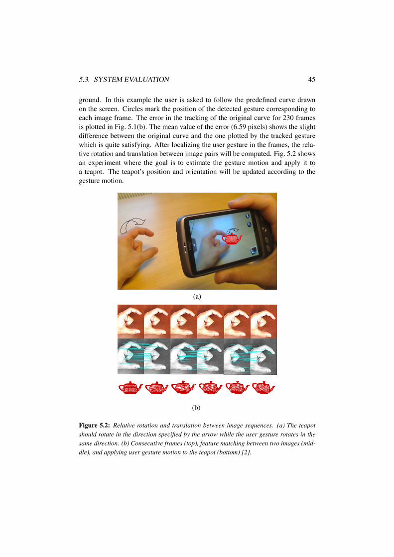
ground. In this example the user is asked to follow the predefined curve drawnon the screen. Circles mark the position of the detected gesture corresponding toeach image frame. The error in the tracking of the original curve for 230 framesis plotted in Fig. 5.1(b). The mean value of the error (6.59 pixels) shows the slightdifference between the original curve and the one plotted by the tracked gesturewhich is quite satisfying. After localizing the user gesture in the frames, the rela-tive rotation and translation between image pairs will be computed. Fig. 5.2 showsan experiment where the goal is to estimate the gesture motion and apply it toa teapot. The teapot’s position and orientation will be updated according to thegesture motion.
(a)
(b)
Figure 5.2: Relative rotation and translation between image sequences. (a) The teapotshould rotate in the direction specified by the arrow while the user gesture rotates in thesame direction. (b) Consecutive frames (top), feature matching between two images (mid-dle), and applying user gesture motion to the teapot (bottom) [2].

46CHAPTER 5. EVALUATION OF HAND GESTURE RECOGNITION SYSTEM

Part IV
APPLICATION DOMAINS


Chapter 6
Applications
The potential applications of human motion analysis can be categorized into threemajor domains: surveillance, control, and analysis. The surveillance area cov-ers applications where one or more subjects are being tracked and monitored forspecial actions. The control area relates to applications where the captured mo-tion is used to provide controlling functionalities, and the third application area isconcerned with the detailed analysis of the captured motion data.
Considering this classification, a few application areas are presented, in whichhuman motion estimation has and will continue to have a profound impact.
6.1 Application areas
• Video Surveillance: A classic example is the bank surveillance system [74],where human motion estimation provides system controllers with the abilityto closely monitor the activities of employees and customers to evaluatewhether they may be about to commit a crime.
• Intelligent Environments: Head pose estimation systems will play a key rolein the creation of intelligent environments. Already there has been a hugeinterest in smart rooms that monitor the occupants and use head pose tomeasure their activities and visual focus of attention [75] [76] [77]. Headpose endows these systems with the ability to determine who is speakingto whom, and to provide the information needed to analyze the non-verbalgestures of the meeting participants.
• Virtual Reality: Human gestures for virtual and augmented reality applica-tions have experienced one of the greatest levels of uptake in computing.Virtual reality interactions use gestures to enable realistic manipulations of
49

50 CHAPTER 6. APPLICATIONS
virtual objects using users hands, for 3D display interactions [78] or 2D dis-plays that simulate 3D interactions [79].
• Robotics and Telepresence: Telepresence and telerobotic applications aretypically situated within the domain of space exploration and military-basedresearch projects. The gestures used to interact with and control robots aresimilar to fully-immersed virtual reality interactions, however the worlds areoften real, presenting the operator with video feed from cameras located onthe robot [80]. Here, gestures can control a robot’s hand and arm movementsto reach for and manipulate actual objects in the world.
• Desktop and Mobile-device Applications: In desktop computing, gesturescan provide an alternative interaction to the mouse and keyboard [81]. Manygestures for desktop computing tasks involve manipulating graphics, or an-notating and editing documents using pen-based gestures [82]. Head poseestimation could enable breakthrough interfaces for computing. Some exist-ing examples include systems that allow a user to control a computer mouseusing his head pose movements [83], respond to pop-up dialog boxes withhead nods and shakes [84], or use head gestures to interact with embodiedagents [85].
• Entertainment: Tracking and analyzing human body movements and ges-tures can enrich experience of computer games as well. Freeman et al. [86]tracked a player’s hand or body position to control movement and orientationof interactive game objects such as cars. Konrad et al. [87] used gestures tocontrol the movement of avatars in a virtual world. Recently, game consolemanufactures have provided new devices that allow players to interact withgames using motion, and also sound. Sony has introduced the PLAYSTA-TIONEYE, a camera that tracks hand movements for interactive games [88],and Microsoft has released Kinect for Xbox 360 which can detect and trackhuman gestures to control and manipulate interactive game objects [21].
• Medical Applications: Movement disorder clinics and health care systemscan also benefit from human motion analysis. Movement disorders affectspeed, quality, and ease of human movements, and in many cases, surgicalintervention is the best possible treatment for such a disease. Vision-basedmotion capture systems endow clinicians to observe patient’s improvementsafter surgical operation [15] [16] [17].
• Automotive Safety: Head pose estimation will have a profound impact on thefuture of automotive safety. An automobile driver is fundamentally limitedby the field-of-view that one can observe at any one time. When one fails to

6.1. APPLICATION AREAS 51
notice a change to his environment, there is an increased potential for a life-threatening collision that could be mitigated if the driver was alerted to anunseen hazard. As evidence to this effect, a recent comprehensive survey onautomotive collisions demonstrated a driver was 31% less likely to cause aninjury-related collision when there was one or more passengers [89]. Conse-quently, there is great interest in driver assistance systems that act as virtualpassengers, using the driver’s head pose as a cue to visual focus of attentionand mental state [90] [91] [92].

52 CHAPTER 6. APPLICATIONS

Part V
CONTRIBUTIONS,DISCUSSIONS, AND FUTURE
DIRECTIONS

Chapter 7
Outline and Summary ofContributions
7.1 Summary of contributed papers
Paper IFarid Abedan Kondori, Li Liu, “3D Active Human Motion Estimation for Biomed-ical Applications,” accepted in World Congress on Medical Physics and Biomed-ical Engineering (WC2012), Beijing, China, 26-31 May 2012.
Movement disorders prevent many people from enjoying their daily lives. As withother diseases, diagnosis and analysis are key issues in treating such disorders.Vision-based motion capture systems are helpful tools for accomplishing this task.However Classical motion tracking systems suffer from several limitations. First,they are not cost effective. Second, these systems cannot detect minute motionsaccurately. Finally, they are spatially limited to the lab environment where thesystem is installed. In this project, we propose an innovative solution to solve theaforementioned issues. Mounting the camera on human body, we build a conve-nient, low cost motion capture system that can be used by the patient in daily-lifeactivities. We refer to this system as active motion capture, which is not confinedto the lab environment. Real-time experiments in our lab revealed the robustnessand accuracy of the system.
Paper IIFarid Abedan Kondori, Shahrouz Yousefi, Haibo Li, Samuel Sonning, Sabina Son-ning, “3D Head Pose Estimation Using the Kinect,” in International Conferenceon Wireless Communications and Signal Processing (WCSP2011), Nanjing, China, 9-11 November 2011, pp.1-4.
55

56 CHAPTER 7. OUTLINE AND SUMMARY OF CONTRIBUTIONS
Head pose estimation plays an essential role for bridging the information gap be-tween humans and computers. Conventional head pose estimation methods aremostly based on the RGB images. However accurate and robust head pose estima-tion is often problematic. In this paper we present an algorithm for recovering thesix degrees of freedom (DOF) of motion of a head from a sequence of range imagestaken by Kinect. The proposed algorithm utilizes a least-squares minimization ofthe difference between the measured rate of change of depth at a point and the ratepredicted by the depth rate constraint equation. We segment the human head fromits surroundings and background, and then we estimate the head motion. Our sys-tem has the capability to recover the head motion of multiple people in one image.The proposed system is evaluated in our lab and presents superior results.
Paper IIIShahrouz Yousefi, Farid Abedan Kondori, Haibo Li, “Tracking Fingers in 3DSpace for Mobile Interaction,” in The Second International Workshop on MobileMultimedia Processing (WMMP2010), Istanbul, Turkey, August 2010, pp.72-79.
Designing a robust hand gesture detection system using a single camera indepen-dent of lighting conditions or camera quality is still a challenging issue in the fieldof computer vision. A common method for gesture detection is marker-based ap-proach. Most of the augmented reality applications are based on marked gloves foraccurate and reliable fingertip tracking. However, in marker-based methods usershave to wear special inconvenient markers. What we present in this paper is simplybased on low level operators, detecting natural features without any effort to havean intelligent system. We propose a way to take advantage of lines, curvatures,circular patterns and in general rotational symmetries associated with the model ofthe human fingers which leads to the detection of the human gesture.
Paper IVFarid Abedan Kondori, Shahrouz Yousefi, Haibo Li, “Real 3D Interaction Be-hind Mobile Phones for Augmented Environments,” in IEEE International Con-ference on Multimedia and Expo (ICME2011), Barcelona, Spain, 11-15 July 2011,pp.1-6.
New mobile devices are equipped with integrated cameras and large displays whichmake the interaction with device easier and more efficient. Although most of theprevious works on interaction between humans and mobile devices are based on2D touch-screen displays, camera-based interaction opens a new way to manip-ulate in 3D space behind the device in the camera’s field of view. This paper

7.2. SUMMARY OF CONTRIBUTIONS 57
suggests the use of particular patterns from local orientation of input image calledrotational symmetries to detect and localize human gesture. Relative rotation andtranslation of human gesture between consecutive frames are estimated by meansof extracting stable features. Consequently, this information can be used to fa-cilitate the 3D manipulation of virtual objects in various applications in mobiledevices.
7.2 Summary of contributions
The contributions from this thesis can be divided into two areas. The key contri-butions to each area are presented here.
3D head pose estimation. The contributions to this area are from the papers Iand II.
• Developing active motion capture system by mounting cameras on the hu-man body, to provide higher resolution, and to overcome the problems of theexisting human motion analysis systems.
• 3D linear head pose estimation method for directly recovering head motionparameters from a sequence of range images.
Hand gesture motion estimation. The contributions to this area are from thepapers III and IV.
• Hand gesture detection and tracking algorithm based on the very low-leveloperations with the minimum level of intelligence.
• Hand gesture motion recovery by means of extracting stable features in thescene to develop new human mobile interaction systems.

58 CHAPTER 7. OUTLINE AND SUMMARY OF CONTRIBUTIONS

Chapter 8
Concluding Remarks & FutureDirections
In the previous chapters current human motion capture systems have been re-viewed (Chapter 1), active and passive head pose estimation methods have beenpresented (Chapter 2), hand gesture recognition and tracking scheme has been dis-cussed (Chapter 3), and experimental results have been demonstrated (Chapter 4and 5). In this chapter, the concluding remarks based on the four research studiesconducted by the author and colleagues are summarized.
8.1 Conclusions
• We have proposed an active approach to capture human head motion. Mount-ing the camera on the head, we have built a convenient, low cost motioncapture system that can be used by users even in daily-life activities. Scalechanges, human occlusion, and cluttered scenes do not affect the systemperformance any longer. Additionally, active motion capture system is notconfined to the lab environments, and provides high resolution and accu-racy. However, detecting sufficient number of interest points in the scene isthe only requirement for the proposed method.
• We have developed a passive head pose estimation system based on thedepth information from range images. Our method is able to linearly es-timate the 3D head pose of multiple persons in one image. Moreover ouralgorithm is identity and lighting invariant and works across all identitieswith the dynamic lighting condition. It can apply to near-field and far-fieldimages with both high and low resolutions as well.
59

60 CHAPTER 8. CONCLUDING REMARKS & FUTURE DIRECTIONS
Although the experiments show the robustness and efficiency of the system,our method has high dependency on accurate head detection, which impliesthat if user is wearing a strange shape hat, or unusual hair style, it proba-bly will degrade the head detection performance. The integration of RGBimages into depth arrays can improve the head detection algorithm.
• Despite the fact that the passive approach is more robust against the lightingvariations than the active approach, a few limitations are associated with thepassive method in comparison with the active motion analysis system. First,the passive system needs initialization step. The head has to be detected andlocalized to estimate the head motion. Thus, wrong head detection and lo-calization would affect the system performance. Second, the passive methodis spatially limited. The user must be placed in front of the sensor, with theresult that analyzing user movements during daily life activities is very un-likely. Last but certainly not least, small head movements cannot be detectedaccurately by the passive approach. Higher resolution in the active systemresults in estimating small movements accurately.
• We have also presented a novel approach for hand gesture motion estima-tion. Our detection algorithm can estimate the position of hand gesture inconsecutive frames. This algorithm is computationally efficient and relieson low level operations, detecting natural features without any effort to havean intelligent system. Then the relative hand motion between two consec-utive frames is estimated, which can be used to facilitate a diverse set ofapplications.
8.2 Future directions
The research presented in this thesis still leaves some open questions concerningimproving the vision-based motion capture system, and implementing it in otherrelated areas.
• Future research
There are two areas where further research is planned. First, we plan to apply datamining to the active motion capture system, to develop new vision-based theories.Second, improving the gesture recognition system to detect and recognize a widerange of hand gestures.

8.2. FUTURE DIRECTIONS 61
• Future implementations
There are numerous 3D visualization systems which can benefit from human mo-tion estimation. In our lab, we have planned to implement 3D head motion analysisto these systems to enhance the quality of 3D experience. We also have a vision totake the advantage of head motion estimation to make a major breakthrough in the3D displays in the future.

62 CHAPTER 8. CONCLUDING REMARKS & FUTURE DIRECTIONS

BIBLIOGRAPHY


Bibliography
[1] B. Rosenhahn, R. Klette, and D. Metaxas, Human motion: understanding, modeling,capture and animation. Computational imaging and vision, Springer, 2008.
[2] F. A. Kondori, S. Yousefi, and H. Li, “Real 3d interaction behind mobile phonesfor augmented environments,” in Multimedia and Expo (ICME), 2011 IEEE Interna-tional Conference on, pp. 1 –6, july 2011.
[3] F. A. Kondori and L. Liu, “3D Active Human Motion Estimation for BiomedicalApplications,” 26-31 May 2012. accepted in World Congress on Medical Physicsand Biomedical Engineering (WC2012), Beijing, China.
[4] F. A. Kondori, S. Yousefi, H. Li, S. Sonning, and S. Sonning, “3D head pose esti-mation using the Kinect,” 9-11 Nov. 2011. In Proceeding of The 2011 IEEE Inter-national Conference on Wireless Communications and Signal Processing (WCSP),Nanjing, China, p. 1 - 4.
[5] S. Yousefi, F. A. Kondori, and H. Li, “Tracking Fingers in 3D Space for MobileInteraction,” August 2010. In Proceeding of The 20th International Conference onPattern Recognition (ICPR), The Second International Workshop on Mobile Multi-media Processing (WMMP), Istanbul, Turkey.
[6] E. Muybridge, Muybridge’s Complete human and animal locomotion: all 781 platesfrom the 1887 Animal locomotion. Muybridge’s Complete Human and Animal Lo-comotion: All 781 Plates from the 1887 Animal Locomotion, Dover Publications,1979.
[7] F. Foerster, “Detection of posture and motion by accelerometry: a validation study inambulatory monitoring,” Computers in Human Behavior, vol. 15, no. 5, pp. 571–583,1999.
[8] G. Kamen, C. Patten, C. D. Du, and S. Sison, “An accelerometry-based system forthe assessment of balance and postural sway.,” Gerontologia (Basel), vol. 44, no. 1,pp. 40–45, 1998.
[9] C. Bouten, K. Koekkoek, M. Verduin, R. Kodde, and J. Janssen, “A triaxial ac-celerometer and portable data processing unit for the assessment of daily physicalactivity,” Biomedical Engineering, IEEE Transactions on, vol. 44, pp. 136 –147,march 1997.
65

66 BIBLIOGRAPHY
[10] H. J. Luinge and P. H. Veltink, “Measuring orientation of human body segmentsusing miniature gyroscopes and accelerometers.,” Medical & biological engineering& computing, vol. 43, pp. 273–282, Mar. 2005.
[11] B. Kemp, A. J. Janssen, and B. Van Der Kamp, “Body position can be monitoredin 3d using miniature accelerometers and earth-magnetic field sensors.,” Electroen-cephalography and Clinical Neurophysiology, vol. 109, no. 6, pp. 484–488, 1998.
[12] O. Suess, S. Suess, S. Mularski, B. Kuhn, T. Picht, S. Hammersen, R. Stendel,M. Brock, and T. Kombos, “Study on the clinical application of pulsed dc magnetictechnology for tracking of intraoperative head motion during frameless stereotaxy,”Head & Face Medicine, vol. 2, no. 1, p. 10, 2006.
[13] E. R. Bachmann, R. B. McGhee, X. Yun, and M. J. Zyda, “Inertial and magnetic pos-ture tracking for inserting humans into networked virtual environments,” in In ACMSymposium on Virtual Reality Software and Technology (VRST, pp. 9–16, ACM,2001.
[14] H. Zheng, N. Black, and N. Harris, “Position-sensing technologies for movementanalysis in stroke rehabilitation,” Medical and Biological Engineering and Comput-ing, vol. 43, pp. 413–420, 2005. 10.1007/BF02344720.
[15] I. Davis, S. Ounpuu, D. Tyburski, and J. R. Gage, “A gait analysis data collection andreduction technique,” Human Movement Science, vol. 10, pp. 575–587, Oct. 1991.
[16] I. Charlton, P. Tate, P. Smyth, and L. Roren, “Repeatability of an optimised lowerbody model,” Gait & Posture, vol. 20, no. 2, pp. 213 – 221, 2004.
[17] E. Delahunt, K. Monaghan, and B. Caulfield, “Ankle function during hopping insubjects with functional instability of the ankle joint.,” Scandinavian Journal ofMedicine & Science in Sports, vol. 17, no. 6, pp. 641–648, 2007.
[18] T. B. Moeslund and E. Granum, “A survey of computer vision-based human motioncapture,” 1999.
[19] J. K. Aggarwal and Q. Cai, “Human motion analysis: A review,” Computer Visionand Image Understanding, vol. 73, pp. 428–440, 1999.
[20] H. Zhou and H. Hu, “Human motion tracking for rehabilitation – a survey,” 2008.
[21] http://research.microsoft.com/en us/um/redmond/projects/kinectsdk/default.aspx.
[22] D. Lowe, “Distinctive image features from scale-invariant keypoints,” 2004. Int. J.of Computer Vision 60, 2, 91.110.
[23] E. O. Heierman, D. J. Cook, S. K. Das, and L. B. Holder, “Moving from internetappliances to internet intelligent abstract environments: Challenges and directions,”2008.
[24] M. Turk and G. Robertson, “Perceptual user interfaces,” Communications of theACM, vol. 43, pp. 33–34, 2000.
[25] http://www.pdf.org/en/pd_comm_news/release/pr_1216910017.

BIBLIOGRAPHY 67
[26] J.-P. Bach, U. Ziegler, G. Deuschl, R. Dodel, and G. Doblhammer-Reiter, “Projectednumbers of people with movement disorders in the years 2030 and 2050,” MovementDisorders, vol. 26, no. 12, pp. 2286–2290.
[27] http://www.idc.com/getdoc.jsp?containerId=prUS22871611.
[28] http://www.intomobile.com/2010/12/14/goldman-sachs tablets/.
[29] http://www.gartner.com/it/page.jsp?id=1570714.
[30] J. Ng and S. Gong, “Composite support vector machines for detection of faces acrossviews and pose estimation,” Image and Vision Computing, vol. 20, pp. 359–368, Apr.2002.
[31] J. Ng and S. Gong, “Multi-view face detection and pose estimation using a compositesupport vector machine across the view sphere,” in Recognition, Analysis, and Track-ing of Faces and Gestures in Real-Time Systems, 1999. Proceedings. InternationalWorkshop on, pp. 14 –21, 1999.
[32] J.-G. Wang and E. Sung, “Em enhancement of 3d head pose estimated by point atinfinity,” Image Vision Comput., vol. 25, pp. 1864–1874, December 2007.
[33] H. R. Wilson, F. Wilkinson, L. M. Lin, and M. Castillo, “Perception of head orienta-tion.,” Vision Research, vol. 40, no. 5, pp. 459–472, 2000.
[34] S. Ohayon and E. Rivlin, “Robust 3d head tracking using camera pose estimation,”in In 18th International Conference on Pattern Recognition (ICPR, pp. 1063–1066,2006.
[35] G. Zhao, L. Chen, J. Song, and G. Chen, “Large head movement tracking usingsift-based registration,” in Proceedings of the 15th international conference on Mul-timedia, MULTIMEDIA ’07, (New York, NY, USA), pp. 807–810, ACM, 2007.
[36] P. Pérez, C. Hue, J. Vermaak, and M. Gangnet, “Color-based probabilistic tracking,”in In Proc. ECCV, pp. 661–675, 2002.
[37] N. T. Siebel and S. J. Maybank, “Fusion of multiple tracking algorithms for ro-bust people tracking,” in Proceedings of the 7th European Conference on ComputerVision-Part IV, ECCV ’02, (London, UK, UK), pp. 373–387, Springer-Verlag, 2002.
[38] T. Zhao and R. Nevatia, “Tracking multiple humans in complex situations,” IEEETransactions on Pattern Analysis and Machine Intelligence, vol. 26, pp. 1208–1221,2004.
[39] V. Ganapathi, C. Plagemann, D. Koller, and S. Thrun, “Real time motion captureusing a single time-of-flight camera,” in IEEE Conference on Computer Vision andPattern Recognition (CVPR, 2010.
[40] H. P. Jain, A. Subramanian, S. Das, and A. Mittal, “Real-time upper-body humanpose estimation using a depth camera,” in Proceedings of the 5th internationalconference on Computer vision/computer graphics collaboration techniques, MI-RAGE’11, (Berlin, Heidelberg), pp. 227–238, Springer-Verlag, 2011.

68 BIBLIOGRAPHY
[41] J. Rodgers, D. Anguelov, H.-C. Pang, and D. Koller, “Object pose detection in rangescan data,” in Computer Vision and Pattern Recognition, 2006 IEEE Computer Soci-ety Conference on, vol. 2, pp. 2445 – 2452, 2006.
[42] Y. Zhu, B. Dariush, and K. Fujimura, “Controlled human pose estimation fromdepth image streams,” in Computer Vision and Pattern Recognition Workshops, 2008.CVPRW ’08. IEEE Computer Society Conference on, pp. 1 –8, june 2008.
[43] Z. Yao, Model-based Coding - Initialization, Parameter Extraction and Evaluation.PhD thesis, 2005.
[44] B. D. Lucas and T. Kanade, “An iterative image registration technique with an appli-cation to stereo vision,” pp. 674–679, 1981.
[45] R. B. M. Fischler, “Random sample consensus: a paradigm for model fitting withapplications to image analysis and automated cartography,” 1987. Readings in com-puter vision: issues, problems, principles, and paradigms, 726.740.
[46] A. Z. R. I. Hartley, “Multiple view geometry,” 2004. Cambridge University Press,Cambridge, UK.
[47] B. Horn, Robot vision:. MIT electrical engineering and computer science series, MITPress, 1986.
[48] https://github.com/OpenKinect/libfreenect.
[49] http://openkinect.org/wiki/Imaging_Information.
[50] B. K. P. Horn and J. G. Harris, “Rigid body motion from range image sequences,”1991.
[51] B. K. P. Horn and E. J. Weldon, “Direct methods for recovering motion,” Interna-tional Journal of Computer Vision, vol. 2, no. 1, pp. 51–76, 1988.
[52] B. K. P. Horn, Robot Vision (MIT Electrical Engineering and Computer Science).The MIT Press, mit press ed ed., Mar. 1986.
[53] F. K. H. Quek, “Toward a vision-based hand gesture interface,” in Proceedings ofthe conference on Virtual reality software and technology, (River Edge, NJ, USA),pp. 17–31, World Scientific Publishing Co., Inc., 1994.
[54] F. Quek, “Eyes in the interface,” Image and Vision Computing, vol. 13, pp. 511–525,Aug. 1995.
[55] T. Baudel and M. Beaudouin-Lafon, “Charade: Remote control of objects using free-hand gestures,” Communications of the ACM, vol. 36, pp. 28–35, 1993.
[56] S. Fels and G. Hinton, “Glove-talk: a neural network interface between a data-gloveand a speech synthesizer,” Neural Networks, IEEE Transactions on, vol. 4, pp. 2 –8,jan 1993.
[57] D. Sturman and D. Zeltzer, “A survey of glove-based input,” Computer Graphics andApplications, IEEE, vol. 14, pp. 30 –39, jan 1994.

BIBLIOGRAPHY 69
[58] J. Kuch and T. Huang, “Vision based hand modeling and tracking for virtual tele-conferencing and telecollaboration,” in Computer Vision, 1995. Proceedings., FifthInternational Conference on, pp. 666 –671, jun 1995.
[59] J. Lee and T. Kunii, “Model-based analysis of hand posture,” Computer Graphicsand Applications, IEEE, vol. 15, pp. 77 –86, sep 1995.
[60] J. M. Rehg and T. Kanade, “Visual tracking of high dof articulated structures: an ap-plication to human hand tracking,” in Proceedings of the third European conferenceon Computer Vision (Vol. II), ECCV ’94, (Secaucus, NJ, USA), pp. 35–46, Springer-Verlag New York, Inc., 1994.
[61] B. Stenger, P. Mendonca, and R. Cipolla, “Model-based 3d tracking of an articulatedhand,” in Computer Vision and Pattern Recognition, 2001. CVPR 2001. Proceedingsof the 2001 IEEE Computer Society Conference on, vol. 2, pp. II–310 – II–315 vol.2,2001.
[62] Y. Wu, J. Lin, and T. Huang, “Capturing natural hand articulation,” in ComputerVision, 2001. ICCV 2001. Proceedings. Eighth IEEE International Conference on,vol. 2, pp. 426 –432 vol.2, 2001.
[63] B. Stenger, A. Thayananthan, P. Torr, and R. Cipolla, “Model-based hand trackingusing a hierarchical bayesian filter,” Pattern Analysis and Machine Intelligence, IEEETransactions on, vol. 28, pp. 1372 –1384, sept. 2006.
[64] M. J. Black and A. D. Jepson, “Eigentracking: Robust matching and tracking of artic-ulated objects using a view-based representation,” International Journal of ComputerVision, vol. 26, pp. 63–84, 1998. 10.1023/A:1007939232436.
[65] Y. Cui and J. Weng, “Hand sign recognition from intensity image sequences withcomplex backgrounds,” in Automatic Face and Gesture Recognition, 1996., Pro-ceedings of the Second International Conference on, pp. 259 –264, oct 1996.
[66] T. Darrell and A. Pentland, “Space-time gestures,” in Computer Vision and PatternRecognition, 1993. Proceedings CVPR ’93., 1993 IEEE Computer Society Confer-ence on, pp. 335 –340, jun 1993.
[67] M. P. D. R. S. C. S. . B. S. Gupta, N., “Developing a gesture-based interface,” IETEJournal of Research,, vol. 48, no. 3, p. 237U244, 2002.
[68] T. Starner, J. Weaver, and A. Pentland, “Real-time american sign language recogni-tion using desk and wearable computer based video,” Pattern Analysis and MachineIntelligence, IEEE Transactions on, vol. 20, pp. 1371 –1375, dec 1998.
[69] R. Cutler and M. Turk, “View-based interpretation of real-time optical flow for ges-ture recognition,” in Automatic Face and Gesture Recognition, 1998. Proceedings.Third IEEE International Conference on, pp. 416 –421, apr 1998.
[70] M.-H. Yang, N. Ahuja, and M. Tabb, “Extraction of 2d motion trajectories and itsapplication to hand gesture recognition,” Pattern Analysis and Machine Intelligence,IEEE Transactions on, vol. 24, pp. 1061 – 1074, aug 2002.

70 BIBLIOGRAPHY
[71] B. Johansson, Low Level Operations and Learning in Computer Vision. PhD the-sis, Linköping University, Sweden, SE-581 83 Linköping, Sweden, December 2004.Dissertation No. 912, ISBN 91-85295-93-0.
[72] E. Murphy-Chutorian and M. Trivedi, “Head pose estimation in computer vision: Asurvey,” Pattern Analysis and Machine Intelligence, IEEE Transactions on, vol. 31,pp. 607 –626, april 2009.
[73] http://opencv.willowgarage.com/wiki/.
[74] Y. Wu, “Research on bank intelligent video image processing and monitoring con-trol system based on opencv,” in Anti-counterfeiting, Security, and Identification inCommunication, 2009. ASID 2009. 3rd International Conference on, pp. 211 –214,aug. 2009.
[75] M. M. Trivedi, “Human movement capture and analysis in intelligent environments,”Mach. Vision Appl., vol. 14, pp. 215–217, September 2003.
[76] M. Trivedi, K. Huang, and I. Mikic, “Dynamic context capture and distributed videoarrays for intelligent spaces,” Systems, Man and Cybernetics, Part A: Systems andHumans, IEEE Transactions on, vol. 35, pp. 145 – 163, jan. 2005.
[77] J. Tu, T. Huang, and H. Tao, “Accurate head pose tracking in low resolution video,” inAutomatic Face and Gesture Recognition, 2006. FGR 2006. 7th International Con-ference on, pp. 573 –578, april 2006.
[78] R. Sharma, T. Huang, V. Pavlovic, Y. Zhao, Z. Lo, S. Chu, and K. Schul,“Speech/gesture interface to a visual computing environment for molecular biolo-gists,” in Pattern Recognition, 1996., Proceedings of the 13th International Confer-ence on, vol. 3, pp. 964 –968 vol.3, aug 1996.
[79] T. S. Jake, J. Auxier, and D. Ashbrook, “The gesture pendant: A self-illuminating,wearable, infrared computer vision system for home automation control and medicalmonitoring,” in In International Symposium on Wearable Computing, pp. 87–94,2000.
[80] S. M. Goza, R. O. Ambrose, M. A. Diftler, and I. M. Spain, “Telepresence controlof the nasa/darpa robonaut on a mobility platform,” in Proceedings of the SIGCHIconference on Human factors in computing systems, CHI ’04, (New York, NY, USA),pp. 623–629, ACM, 2004.
[81] P. D. Stotts, J. M. Smith, and K. Gyllstrom, “Facespace: endo- and exo-spatial hy-permedia in the transparent video facetop.,” in Hypertext’04, pp. 48–57, 2004.
[82] G. Smith and E. Al., The radial scroll tool: scrolling support for stylus-or touch-based document navigation, vol. 6, pp. 53–56. ACM, 2004.
[83] Y. Fu and T. Huang, “hmouse: Head tracking driven virtual computer mouse,” inApplications of Computer Vision, 2007. WACV ’07. IEEE Workshop on, p. 30, feb.2007.

BIBLIOGRAPHY 71
[84] L.-P. Morency, C. Sidner, C. Lee, and T. Darrell, “Head gestures for perceptual inter-faces: The role of context in improving recognition,” Artif. Intell., vol. 171, pp. 568–585, June 2007.
[85] L. P. Morency, M. C. Christoudias, and T. Darrell, “Recognizing gaze aversion ges-tures in embodied conversational discourse,” in ICMI ’06: Proceedings of the 8thinternational conference on Multimodal interfaces, (New York, NY, USA), pp. 287–294, ACM Press, 2006.
[86] W. Freeman, K. Tanaka, J. Ohta, and K. Kyuma, “Computer vision for computergames,” in Automatic Face and Gesture Recognition, 1996., Proceedings of the Sec-ond International Conference on, pp. 100 –105, oct 1996.
[87] T. Konrad, D. Demirdjian, and T. Darrell, “Gesture + play: full-body interaction forvirtual environments,” in CHI ’03 extended abstracts on Human factors in computingsystems, CHI EA ’03, (New York, NY, USA), pp. 620–621, ACM, 2003.
[88] http://us.playstation.com/corporate/about/press release/396.html.
[89] T. Rueda-Domingo, P. Lardelli-Claret, J. de Dios Luna-del Castillo, J. J. Jimenez-Moleon, M. Garcia-Martin, and A. Bueno-Cavanillas, “The influence of passengerson the risk of the driver causing a car collision in spain: Analysis of collisions from1990 to 1999,” Accident Analysis & Prevention, vol. 36, no. 3, pp. 481 – 489, 2004.
[90] E. Murphy-Chutorian and M. Trivedi, “Hyhope: Hybrid head orientation and posi-tion estimation for vision-based driver head tracking,” in Intelligent Vehicles Sympo-sium, 2008 IEEE, pp. 512 –517, june 2008.
[91] E. Murphy-Chutorian, A. Doshi, and M. Trivedi, “Head pose estimation for driverassistance systems: A robust algorithm and experimental evaluation,” in IntelligentTransportation Systems Conference, 2007. ITSC 2007. IEEE, pp. 709 –714, 30 2007-oct. 3 2007.
[92] J. Wu and M. Trivedi, “Visual modules for head gesture analysis in intelligent vehiclesystems,” in Intelligent Vehicles Symposium, 2006 IEEE, pp. 13 –18, 0-0 2006.