Hum-Power Controller for Powered Wheelchairs A thesis submitted ...
84
Hum-Power Controller for Powered Wheelchairs A thesis submitted in partial fulfillment of the requirements for the degree of Master of Science at George Mason University By Hossein Ghaffari Nik Bachelor of Science George Mason University, 2007 Director: Dr. Nathalia Peixoto, Assistant Professor Department of Electrical and Computer Engineering Summer Semester 2009 George Mason University Fairfax, VA
Transcript of Hum-Power Controller for Powered Wheelchairs A thesis submitted ...
Hum-Power Controller for Powered Wheelchairs
A thesis submitted in partial fulfillment of the requirements for the degree of Master of Science at George Mason University
By
Hossein Ghaffari Nik Bachelor of Science
George Mason University, 2007
Director: Dr. Nathalia Peixoto, Assistant Professor Department of Electrical and Computer Engineering
Summer Semester 2009 George Mason University
Fairfax, VA

ii
Copyright: 2009 Hossein Ghaffari Nik All Rights Reserved

iii
DEDICATION This is dedicated to my family for their never-ending love and support. To my parents, Kazem Ghaffari Nik and Parivash Godazgari without whom I wouldn’t be standing where I am today and to my dearest sister Sara Ghaffari Nik for her love and support.

iv
ACKNOWLEDGEMENTS I would like to thank my advisor Dr. Nathalia Peixoto for her guidance, encouragements and support throughout this project. I would also like to thank East Coast Rehab LLC for their donation to this project and providing us with a powered wheelchair for development and testing.
v
TABLE OF CONTENTS Page
LIST OF TABLES ............................................................................................................. vi
LIST OF FIGURES .......................................................................................................... vii
ABSTRACT ................................................................................................................... ix
CHAPTER 1: INTRODUCTION ...................................................................................... 1
1.1. PROBLEM STATEMENT ......................................................................................... 1 1.2. COMMERCIALLY AVAILABLE SOLUTIONS ............................................................ 2 1.3. PROPOSED SOLUTIONS ......................................................................................... 6
CHAPTER 2: PROTOTYPE DEVELOPMENT ............................................................. 13
2.1. MATLAB ENVIRONMENT .................................................................................... 13 i. GMU Neurot .................................................................................................. 13
2.2. LABVIEW ENVIRONMENT ................................................................................. 22 i. Voice Activated RC Car ................................................................................ 22 ii. Voice Activated Mini Lego Chair ................................................................. 24
CHAPTER 3: MICROCONTROLLER IMPLEMENTATION FOR WHEELCHAIR .. 25
3.1. EVALUATION BOARD ......................................................................................... 25 3.2. DSPIC30F MICROCONTROLLER ......................................................................... 28 3.3. DESIGNED BOARD .............................................................................................. 32
i. Speech Recognition Engine ........................................................................... 32 ii. Humming Detection Technique .................................................................... 36 iii. Powered Wheelchair Interface ...................................................................... 43
3.4. AMBIENT NOISE TEST RESULTS ......................................................................... 49 3.5. FIELD TEST RESULTS ......................................................................................... 57
CHAPTER 4: DISCUSSION ........................................................................................... 58
4.1. WHAT WAS ACHIEVED IN THIS THESIS .............................................................. 58 4.2. FUTURE WORK .................................................................................................. 60
APPENDIX ................................................................................................................... 62
OPERATION MANUAL ..................................................................................................... 62
REFERENCES ................................................................................................................. 68
vi
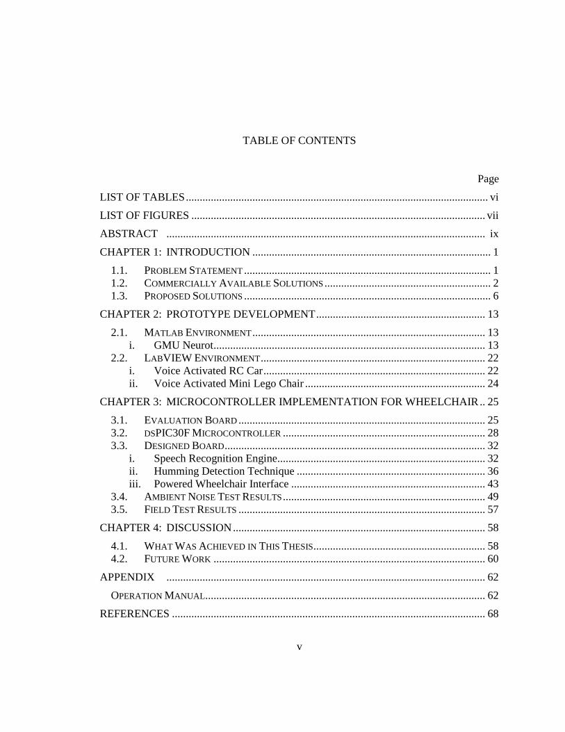
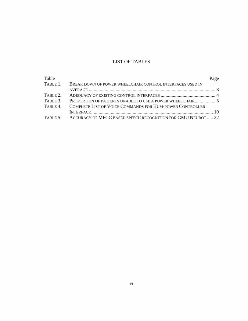
LIST OF TABLES Table Page TABLE 1. BREAK DOWN OF POWER WHEELCHAIR CONTROL INTERFACES USED IN
AVERAGE ........................................................................................................ 3 TABLE 2. ADEQUACY OF EXISTING CONTROL INTERFACES ............................................. 4 TABLE 3. PROPORTION OF PATIENTS UNABLE TO USE A POWER WHEELCHAIR................. 5 TABLE 4. COMPLETE LIST OF VOICE COMMANDS FOR HUM-POWER CONTROLLER
INTERFACE .................................................................................................... 10 TABLE 5. ACCURACY OF MFCC BASED SPEECH RECOGNITION FOR GMU NEUROT ..... 22
vii
LIST OF FIGURES Figure Page FIGURE 1. COMMON COMMERCIALLY AVAILABLE CONTROLLERS FOR POWERED
WHEELCHAIRS ............................................................................................. 3 FIGURE 2. SYSTEMATIC DIAGRAM OF HUM-POWER CONTROLLER FOR POWERED
WHEELCHAIRS ............................................................................................. 8 FIGURE 3. SYSTEM FLOW OF THE HUM-POWER CONTROLLER FOR POWERED
WHEELCHAIRS ............................................................................................. 9 FIGURE 4. GMU NEUROT: THE VOICE ACTIVATED ROBOTIC ARM ............................ 14 FIGURE 5. SPEECH RECOGNITION PROCESS BASED ON MFCC FOR GMU NEUROT .... 15 FIGURE 6. GMU NEUROT'S CONTROL PANEL COMPUTER INTERFACE ........................ 16 FIGURE 7. MFCC REPRESENTATION OF VOICE SIGNAL .............................................. 17 FIGURE 8. CROSS CORRELATION RESULTS FOR THE MFCC'S OF DIFFERENT WORDS . 21 FIGURE 9. VOICE ACTIVATED RC CAR USING LABVIEW .......................................... 23 FIGURE 10. VOICE ACTIVATED MINI LEGO CHAIR USING LABVIEW .......................... 24 FIGURE 11. THE DSPICDEM™ PLUS DEVELOPMENT BOARD WITH MPLAB ICD 2 .... 26 FIGURE 12. DSPIC30F6014A PLUG-IN MODULE .......................................................... 27 FIGURE 13. THE DSPIC30F6014A BLOCK DIAGRAM ................................................... 30 FIGURE 14. OVERVIEW OF SPEECH RECOGNITION ........................................................ 33 FIGURE 15. OVERVIEW OF SPEECH RECOGNITION FLOW DIAGRAM ............................. 35 FIGURE 16. HUM DETECTION BOARD ........................................................................... 37 FIGURE 17. FAST FOURIER TRANSFORM ....................................................................... 38 FIGURE 18. THE FFT DECOMPOSITION ......................................................................... 39 FIGURE 19. THE FFT BIT REVERSAL SORTING ............................................................. 40 FIGURE 20. FLOW DIAGRAM OF THE FFT ..................................................................... 42 FIGURE 21. HUM-POWER CONTROLLER BOARD ........................................................... 45 FIGURE 22. BLOCK DIAGRAM OF THE HUM-POWER CONTROLLER ............................... 46 FIGURE 23. SCHEMATICS OF DSPIC FOR SPEECH RECOGNITION ................................... 47 FIGURE 24. SCHEMATICS OF DSPIC PERFORMING FFT ................................................. 48 FIGURE 25. SCHEMATICS OF SI3000 CODEC ............................................................... 49 FIGURE 26. MEASURED SIGNAL POWER WITHOUT ADDED NOISE ................................. 50 FIGURE 27. MEASURED SIGNAL POWER FOR DIFFERENT WHITE GAUSSIAN NOISE
LEVELS ...................................................................................................... 51 FIGURE 28. CALCULATED NOISE POWER FROM THE MEASURED NOISY SIGNAL .......... 52 FIGURE 29. CALCULATED SIGNAL-TO-NOISE RATIO OF THE MEASURED NOISY SIGNAL
AT DIFFERENT VOLUE LEVELS ................................................................... 53
viii
FIGURE 30. POWER PROFILE FOR THE NOISE SOURCE WITH DIFFERENT INTENSITY LEVELS ...................................................................................................... 54
FIGURE 31. RELIABILITY PROFILE OF SIGNAL POWER MEASUREMENT FOR THE SPOKEN WORDS ...................................................................................................... 55
FIGURE 32. SPEECH RECOGNITION ACCURACY AT DIFFERENT SNR LEVELS ............... 56 FIGURE 33. HUM-POWER CONTROLLER INSTALLED ON POWERED WHEELCHAIR ......... 59
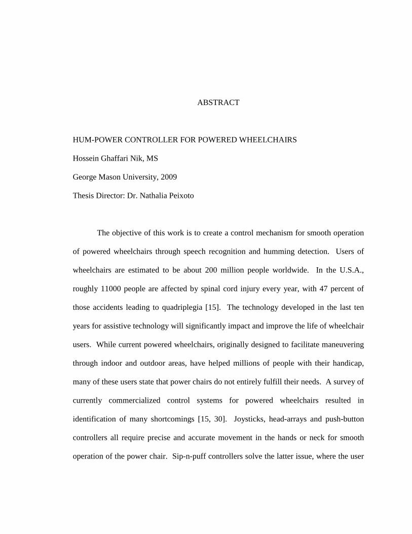
ABSTRACT HUM-POWER CONTROLLER FOR POWERED WHEELCHAIRS Hossein Ghaffari Nik, MS George Mason University, 2009 Thesis Director: Dr. Nathalia Peixoto
The objective of this work is to create a control mechanism for smooth operation
of powered wheelchairs through speech recognition and humming detection. Users of
wheelchairs are estimated to be about 200 million people worldwide. In the U.S.A.,
roughly 11000 people are affected by spinal cord injury every year, with 47 percent of
those accidents leading to quadriplegia [15]. The technology developed in the last ten
years for assistive technology will significantly impact and improve the life of wheelchair
users. While current powered wheelchairs, originally designed to facilitate maneuvering
through indoor and outdoor areas, have helped millions of people with their handicap,
many of these users state that power chairs do not entirely fulfill their needs. A survey of
currently commercialized control systems for powered wheelchairs resulted in
identification of many shortcomings [15, 30]. Joysticks, head-arrays and push-button
controllers all require precise and accurate movement in the hands or neck for smooth
operation of the power chair. Sip-n-puff controllers solve the latter issue, where the user
is able to control the movement of the chair using specific suck and blow operations on a
tube. Although this controller solves the mobility problem of the users, it is still
awkward and unpleasant to use in public [2, 9, 10].
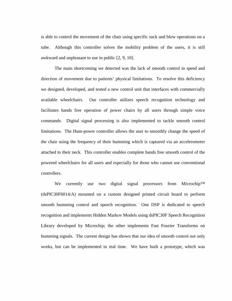
The main shortcoming we detected was the lack of smooth control in speed and
direction of movement due to patients’ physical limitations. To resolve this deficiency
we designed, developed, and tested a new control unit that interfaces with commercially
available wheelchairs. Our controller utilizes speech recognition technology and
facilitates hands free operation of power chairs by all users through simple voice
commands. Digital signal processing is also implemented to tackle smooth control
limitations. The Hum-power controller allows the user to smoothly change the speed of
the chair using the frequency of their humming which is captured via an accelerometer
attached to their neck. This controller enables complete hands free smooth control of the
powered wheelchairs for all users and especially for those who cannot use conventional
controllers.
We currently use two digital signal processors from Microchip™
(dsPIC30F6014/A) mounted on a custom designed printed circuit board to perform
smooth humming control and speech recognition. One DSP is dedicated to speech
recognition and implements Hidden Markov Models using dsPIC30F Speech Recognition
Library developed by Microchip; the other implements Fast Fourier Transforms on
humming signals. The current design has shown that our idea of smooth control not only
works, but can be implemented in real time. We have built a prototype, which was

implemented and tested on Invacare’s Storm TDX5 (mid-wheel drive power chair)
donated to us by East Coast Rehab, LLC.
1
Chapter 1: Introduction 1.1. Problem Statement
Advancements in today’s technology has greatly affected the life of average
people during the past decade, but unfortunately wheelchair users around the world have
seen little to no improvement on the commercially available wheelchair controllers [15].
It is estimated that there are about 200 million people worldwide using wheelchairs and
in the U.S.A. alone roughly 11000 people are affected by spinal cord injury every year.
About 47 percent of those injuries lead to quadriplegia [30]. This growing demand for
wheelchairs calls for better advancements for powered wheelchair controllers to better
suit the needs of these patients.
The extreme difficulty that patients with severe disabilities have been trained to
maneuver a power wheelchair has been described in case studies and subjective evidence
suggests the existence of a patient population for whom mobility is severely limited if not
impossible given currently available power wheelchair control interfaces. An interesting
survey by Hines VA Hospital Rehabilitation Research and Development Center was done
among 200 practicing clinicians, asking them to provide information about their patients
and to give their impressions of the potential usefulness of a new power wheelchair
navigation technology. Significant survey results were [15]:

2
Clinicians indicated that 9 to 10 percent of patients who receive power wheelchair
training find it extremely difficult or impossible to use the wheelchair for activities of
daily living [15]. When asked specifically about steering and maneuvering tasks, the
percentage of patients reported to find these difficult or impossible jumped to 40%.
Eighty-five percent of responding clinicians reported seeing some number of patients
each year that cannot use a power wheelchair because they lack the necessary motor
skills, strength, or visual acuity. Of these clinicians, 32% (27% of all respondents)
reported seeing at least as many patients who cannot use a power wheelchair as who can.
According to this survey nearly half of patients unable to control a power wheelchair by
conventional methods would benefit from an automated navigation system [15].
We believe these results indicate a need, not for more mechanical and systematic
improvement, but for entirely new technologies for supervised autonomous navigation.
This chapter surveys today’s commercially available controllers to power wheelchair
users and then introduces the solution proposed by this thesis to the shortcomings of these
products.
1.2. Commercially Available Solutions
There are many types of commercially available controllers for powered
wheelchairs such as joystick, push-button, head-array and sip-and-puff controllers. All of
these controllers are widely used among wheelchair users with different types of injuries.
The main issue with majority these controllers, except sip-and-puff, is that the patient is
assumed to have reliable mobility in their bodies.
3
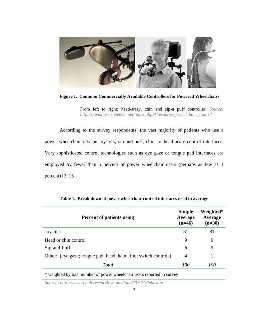
Figure 1. Common Commercially Available Controllers for Powered Wheelchairs
From left to right: head-array, chin and sip-n puff controller. Source: http://atwiki.assistivetech.net/index.php/Alternative_wheelchair_control
According to the survey respondents, the vast majority of patients who use a
power wheelchair rely on joystick, sip-and-puff, chin, or head-array control interfaces.
Very sophisticated control technologies such as eye gaze or tongue pad interfaces are
employed by fewer than 5 percent of power wheelchair users (perhaps as few as 1
percent) [2, 15].
Table 1. Break down of power wheelchair control interfaces used in average
Percent of patients using Simple
Average (n=46)
Weighted* Average (n=30)
Joystick 81 81
Head or chin control 9 9 Sip-and-Puff 6 9 Other: (eye gaze; tongue pad; head, hand, foot switch controls) 4 1
Total 100 100
* weighted by total number of power wheelchair users reported in survey
Source: http://www.rehab.research.va.gov/jour/00/37/3/fehr.htm
4
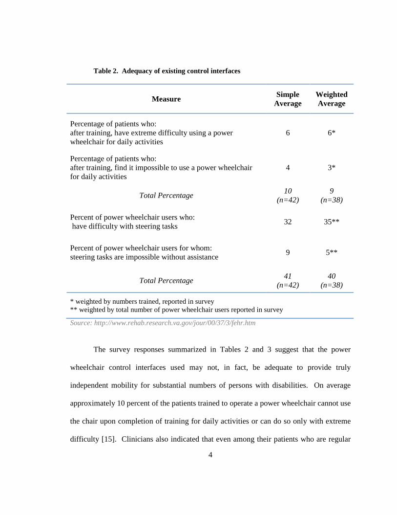
Table 2. Adequacy of existing control interfaces
Measure Simple Average
Weighted Average
Percentage of patients who: after training, have extreme difficulty using a power wheelchair for daily activities
6 6*
Percentage of patients who: after training, find it impossible to use a power wheelchair for daily activities
4 3*
Total Percentage 10 (n=42)
9 (n=38)
Percent of power wheelchair users who: have difficulty with steering tasks 32 35**
Percent of power wheelchair users for whom: steering tasks are impossible without assistance 9 5**
Total Percentage 41 (n=42)
40 (n=38)
* weighted by numbers trained, reported in survey ** weighted by total number of power wheelchair users reported in survey
Source: http://www.rehab.research.va.gov/jour/00/37/3/fehr.htm
The survey responses summarized in Tables 2 and 3 suggest that the power
wheelchair control interfaces used may not, in fact, be adequate to provide truly
independent mobility for substantial numbers of persons with disabilities. On average
approximately 10 percent of the patients trained to operate a power wheelchair cannot use
the chair upon completion of training for daily activities or can do so only with extreme
difficulty [15]. Clinicians also indicated that even among their patients who are regular
5
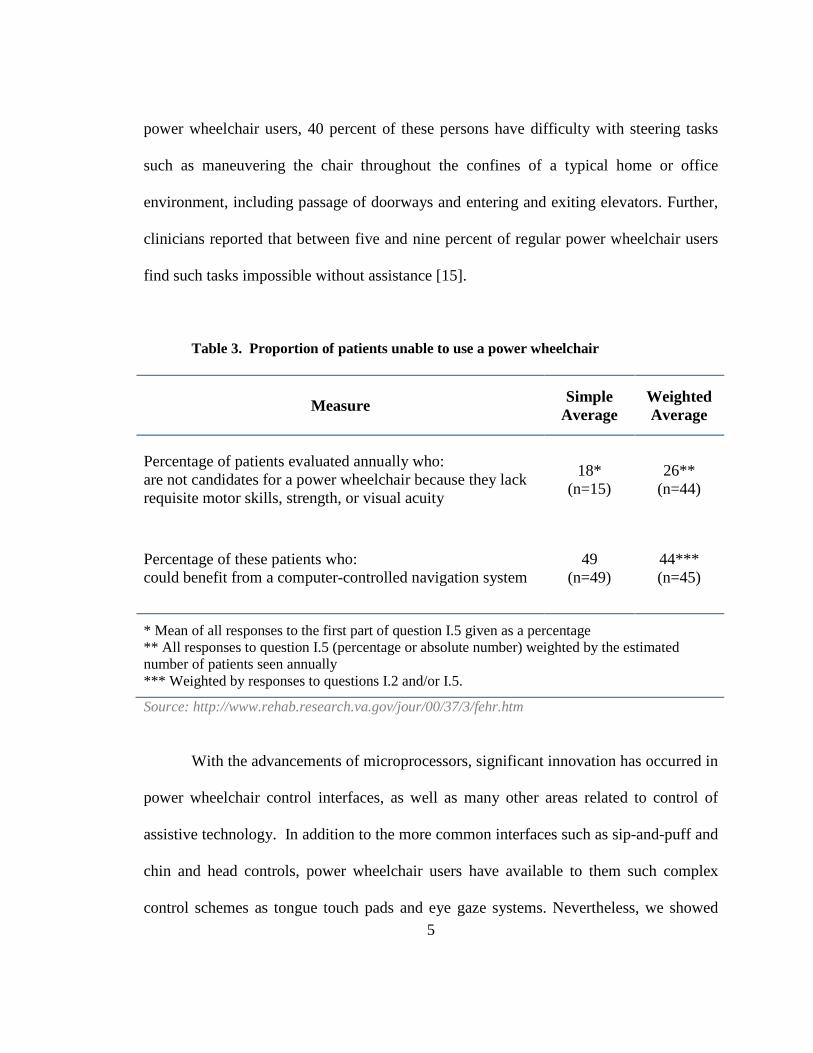
power wheelchair users, 40 percent of these persons have difficulty with steering tasks
such as maneuvering the chair throughout the confines of a typical home or office
environment, including passage of doorways and entering and exiting elevators. Further,
clinicians reported that between five and nine percent of regular power wheelchair users
find such tasks impossible without assistance [15].
Table 3. Proportion of patients unable to use a power wheelchair
Measure Simple Average
Weighted Average
Percentage of patients evaluated annually who: are not candidates for a power wheelchair because they lack requisite motor skills, strength, or visual acuity
18* (n=15)
26** (n=44)
Percentage of these patients who: could benefit from a computer-controlled navigation system
49 (n=49)
44*** (n=45)
* Mean of all responses to the first part of question I.5 given as a percentage ** All responses to question I.5 (percentage or absolute number) weighted by the estimated number of patients seen annually *** Weighted by responses to questions I.2 and/or I.5.
Source: http://www.rehab.research.va.gov/jour/00/37/3/fehr.htm
With the advancements of microprocessors, significant innovation has occurred in
power wheelchair control interfaces, as well as many other areas related to control of
assistive technology. In addition to the more common interfaces such as sip-and-puff and
chin and head controls, power wheelchair users have available to them such complex
control schemes as tongue touch pads and eye gaze systems. Nevertheless, we showed
6
that, in spite of today's sophisticated control interfaces, persons with severe and/or
multiple disabilities may yet find it prohibitively difficult to smoothly steer a power
wheelchair in typical residential, institutional, or office settings in which maneuvering
space is limited. The next section will introduce our solution to a control interface for
smooth and precise control of powered wheelchair that can significantly improve these
current shortcomings.
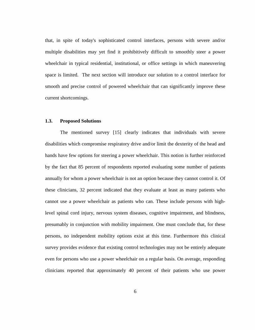
1.3. Proposed Solutions
The mentioned survey [15] clearly indicates that individuals with severe
disabilities which compromise respiratory drive and/or limit the dexterity of the head and
hands have few options for steering a power wheelchair. This notion is further reinforced
by the fact that 85 percent of respondents reported evaluating some number of patients
annually for whom a power wheelchair is not an option because they cannot control it. Of
these clinicians, 32 percent indicated that they evaluate at least as many patients who
cannot use a power wheelchair as patients who can. These include persons with high-
level spinal cord injury, nervous system diseases, cognitive impairment, and blindness,
presumably in conjunction with mobility impairment. One must conclude that, for these
persons, no independent mobility options exist at this time. Furthermore this clinical
survey provides evidence that existing control technologies may not be entirely adequate
even for persons who use a power wheelchair on a regular basis. On average, responding
clinicians reported that approximately 40 percent of their patients who use power

7
wheelchairs have difficulty with steering tasks and that between five and nine percent
find such tasks impossible without assistance [2, 15].
The solution proposed in this work addresses the issue of smooth control for
powered wheelchair users that have limited to no limb movement. In this project we put
forward a controller interface that is easy to be added on commercially available
controllers, such as joysticks, which would enable the voice control of the wheelchair.
Using the Hum-power controller a patient would be able to have a complete control over
their powered wheelchair without requiring any limb movement and to address the
smooth control of the chair for precise maneuvering a novel idea is implemented in the
controller. An issue we encountered in our studies was that when using speech
recognition techniques the user is still bounded to have predefined number of speed
levels. For example; if the speed ranges from 0% to 100% then it is not convenient or
practical to have ten different speed commands for each 10% increments in the speed.
Since there is only a set number of voice commands available, an issue would rise with
the smoothness of the movement in tight areas or for obstacle avoidance. To address this
issue the controller is designed to use and recognize the humming of the patient on their
neck to translate their frequency of humming into the desired speed level. Using this new
technique it is possible to give a precise and smooth control over the speed of the
movement while maneuvering in tight areas.
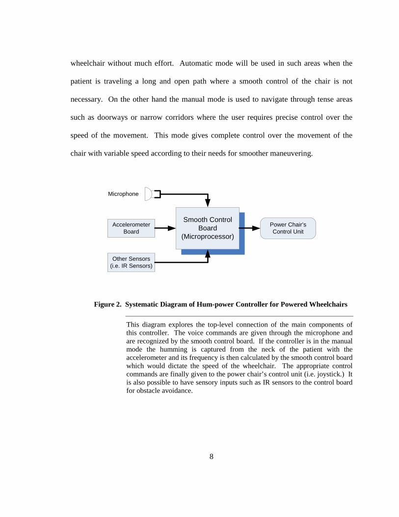
The Hum-power controller presented in this thesis (Figure 2) operates in two
different modes; manual or automatic mode. The precise movement and speed changes
are not always required given that in large and clear areas it is easy to maneuver the
8
wheelchair without much effort. Automatic mode will be used in such areas when the
patient is traveling a long and open path where a smooth control of the chair is not
necessary. On the other hand the manual mode is used to navigate through tense areas
such as doorways or narrow corridors where the user requires precise control over the
speed of the movement. This mode gives complete control over the movement of the
chair with variable speed according to their needs for smoother maneuvering.
Microphone
AccelerometerBoard
Other Sensors(i.e. IR Sensors)
Smooth ControlBoard
(Microprocessor)
Power Chair’s Control Unit
Figure 2. Systematic Diagram of Hum-power Controller for Powered Wheelchairs
This diagram explores the top-level connection of the main components of this controller. The voice commands are given through the microphone and are recognized by the smooth control board. If the controller is in the manual mode the humming is captured from the neck of the patient with the accelerometer and its frequency is then calculated by the smooth control board which would dictate the speed of the wheelchair. The appropriate control commands are finally given to the power chair’s control unit (i.e. joystick.) It is also possible to have sensory inputs such as IR sensors to the control board for obstacle avoidance.
9
Start
Put Chair in Neutral Mode
Start Speech Recognition
Reset for Recognized Maneuver (i.e. Right, Left)
Is Smooth Control Enabled?
Reset Speedto Default
Perform FFT on Accelerometer Data
Match Speedto Frequency of Humming
Send Move Command to the Chair’s Controller
No Yes
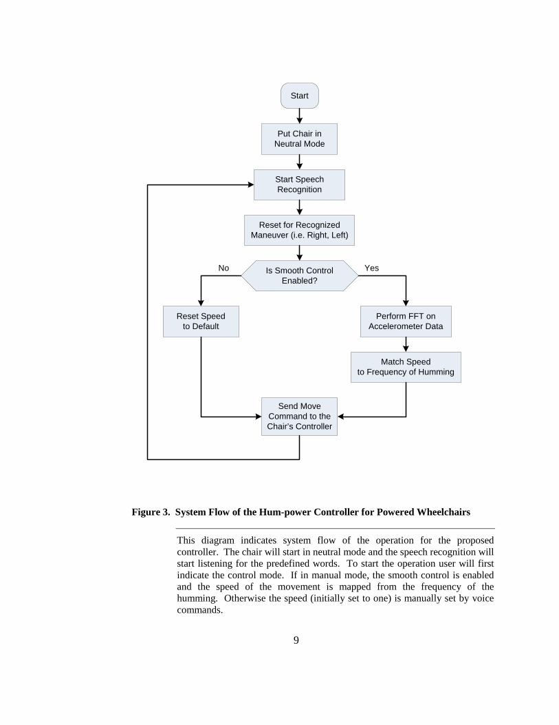
Figure 3. System Flow of the Hum-power Controller for Powered Wheelchairs
This diagram indicates system flow of the operation for the proposed controller. The chair will start in neutral mode and the speech recognition will start listening for the predefined words. To start the operation user will first indicate the control mode. If in manual mode, the smooth control is enabled and the speed of the movement is mapped from the frequency of the humming. Otherwise the speed (initially set to one) is manually set by voice commands.
10
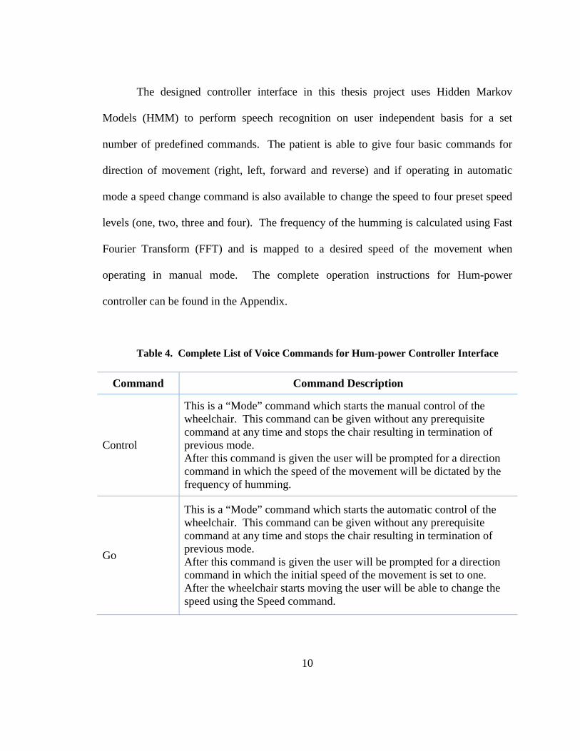
The designed controller interface in this thesis project uses Hidden Markov
Models (HMM) to perform speech recognition on user independent basis for a set
number of predefined commands. The patient is able to give four basic commands for
direction of movement (right, left, forward and reverse) and if operating in automatic
mode a speed change command is also available to change the speed to four preset speed
levels (one, two, three and four). The frequency of the humming is calculated using Fast
Fourier Transform (FFT) and is mapped to a desired speed of the movement when
operating in manual mode. The complete operation instructions for Hum-power
controller can be found in the Appendix.
Table 4. Complete List of Voice Commands for Hum-power Controller Interface
Command Command Description
Control
This is a “Mode” command which starts the manual control of the wheelchair. This command can be given without any prerequisite command at any time and stops the chair resulting in termination of previous mode. After this command is given the user will be prompted for a direction command in which the speed of the movement will be dictated by the frequency of humming.
Go
This is a “Mode” command which starts the automatic control of the wheelchair. This command can be given without any prerequisite command at any time and stops the chair resulting in termination of previous mode. After this command is given the user will be prompted for a direction command in which the initial speed of the movement is set to one. After the wheelchair starts moving the user will be able to change the speed using the Speed command.
11
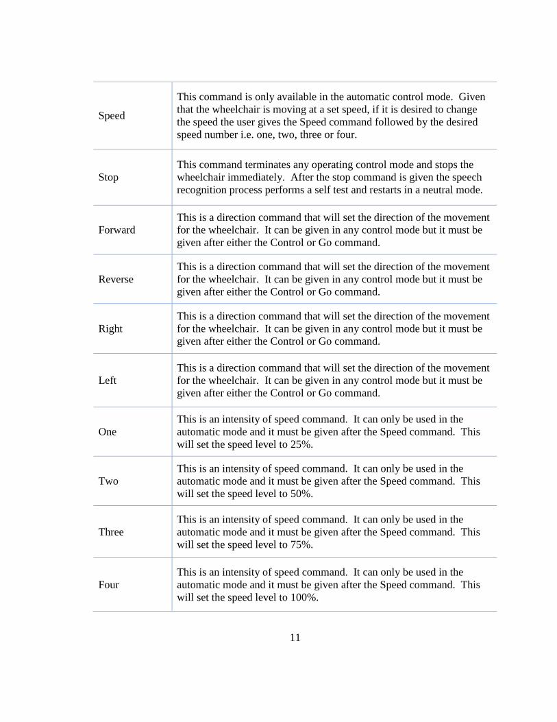
Speed
This command is only available in the automatic control mode. Given that the wheelchair is moving at a set speed, if it is desired to change the speed the user gives the Speed command followed by the desired speed number i.e. one, two, three or four.
Stop This command terminates any operating control mode and stops the wheelchair immediately. After the stop command is given the speech recognition process performs a self test and restarts in a neutral mode.
Forward This is a direction command that will set the direction of the movement for the wheelchair. It can be given in any control mode but it must be given after either the Control or Go command.
Reverse This is a direction command that will set the direction of the movement for the wheelchair. It can be given in any control mode but it must be given after either the Control or Go command.
Right This is a direction command that will set the direction of the movement for the wheelchair. It can be given in any control mode but it must be given after either the Control or Go command.
Left This is a direction command that will set the direction of the movement for the wheelchair. It can be given in any control mode but it must be given after either the Control or Go command.
One This is an intensity of speed command. It can only be used in the automatic mode and it must be given after the Speed command. This will set the speed level to 25%.
Two This is an intensity of speed command. It can only be used in the automatic mode and it must be given after the Speed command. This will set the speed level to 50%.
Three This is an intensity of speed command. It can only be used in the automatic mode and it must be given after the Speed command. This will set the speed level to 75%.
Four This is an intensity of speed command. It can only be used in the automatic mode and it must be given after the Speed command. This will set the speed level to 100%.

12
Other potential solution to the shortcomings of power wheelchair control
technologies is to implement automatic and computerized navigation system to assume
control of steering if required. A computer-controlled power wheelchair navigation
system, which functions in a well-defined but minimally modified environment, has been
developed at the University of Notre Dame, Automation and Robotics Laboratory [45-
48]. The navigation system has repeatedly demonstrated its ability to guide a power
wheelchair along the precise trajectories typically required within a home, office. The
long-term goal of this thesis project is to produce a commercially viable product at a
reasonable price with indoor/outdoor automated navigation capability and added smooth
control facilitation. Such a system would provide persons with severe mobility
impairments a degree of autonomy not otherwise possible [46].
13
Chapter 2: Prototype Development 2.1. MATLAB Environment i. GMU Neurot
The GMU Neurot was designed to develop a straightforward and effective
method for voice recognition which can be easily integrated with the joystick of a
powered wheelchair and enable voice control for quadriplegic and disabled individuals.
In order to completely control Voice Controlled Wheelchairs (VCWs), only some
isolated words need to be recognized (i.e. go, stop, right, left, and backward). The idea
and work done for this project was originally designed, implemented, and tested on a
robotic arm built with the Lego Mindstorms™ NXT (see figure 4).
This robot is capable of drawing a circle, square, or triangle upon command. It is
controlled via USB or Bluetooth connection to a PC; all programming is developed in
Matlab™ 7.1 (Mathworks, Natick, MA). The developed voice recognition algorithm
yields high accuracy in recognizing the words “triangle”, “circle” and “square” with low
ambient noise. In this project a method based on cross correlation of mel frequency
cepstral coefficients (MFCCs) was used for speech recognition of isolated words. We
developed the system and implemented it on three fronts: (1) the robot, (2) computer and
robot interface, and (3) voice recognition program.
14
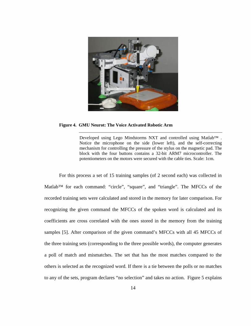
Figure 4. GMU Neurot: The Voice Activated Robotic Arm
Developed using Lego Mindstorms NXT and controlled using Matlab™ . Notice the microphone on the side (lower left), and the self-correcting mechanism for controlling the pressure of the stylus on the magnetic pad. The block with the four buttons contains a 32-bit ARM7 microcontroller. The potentiometers on the motors were secured with the cable ties. Scale: 1cm.
For this process a set of 15 training samples (of 2 second each) was collected in
Matlab™ for each command: “circle”, “square”, and “triangle”. The MFCCs of the
recorded training sets were calculated and stored in the memory for later comparison. For
recognizing the given command the MFCCs of the spoken word is calculated and its
coefficients are cross correlated with the ones stored in the memory from the training
samples [5]. After comparison of the given command’s MFCCs with all 45 MFCCs of
the three training sets (corresponding to the three possible words), the computer generates
a poll of match and mismatches. The set that has the most matches compared to the
others is selected as the recognized word. If there is a tie between the polls or no matches
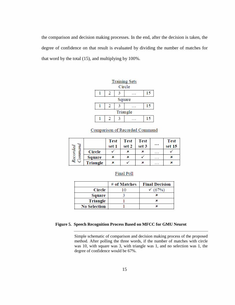
to any of the sets, program declares “no selection” and takes no action. Figure 5 explains
15
the comparison and decision making processes. In the end, after the decision is taken, the
degree of confidence on that result is evaluated by dividing the number of matches for
that word by the total (15), and multiplying by 100%.
Figure 5. Speech Recognition Process Based on MFCC for GMU Neurot
Simple schematic of comparison and decision making process of the proposed method. After polling the three words, if the number of matches with circle was 10, with square was 3, with triangle was 1, and no selection was 1, the degree of confidence would be 67%.
16
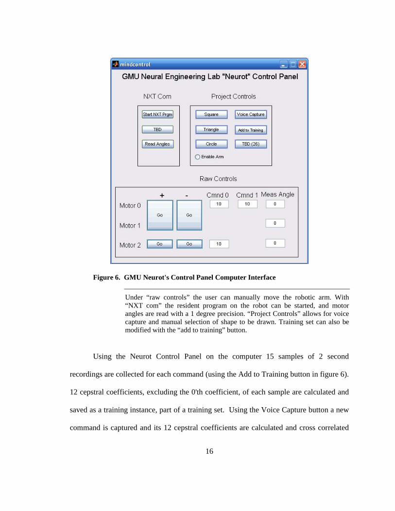
Figure 6. GMU Neurot's Control Panel Computer Interface
Under “raw controls” the user can manually move the robotic arm. With “NXT com” the resident program on the robot can be started, and motor angles are read with a 1 degree precision. “Project Controls” allows for voice capture and manual selection of shape to be drawn. Training set can also be modified with the “add to training” button.
Using the Neurot Control Panel on the computer 15 samples of 2 second
recordings are collected for each command (using the Add to Training button in figure 6).
12 cepstral coefficients, excluding the 0'th coefficient, of each sample are calculated and
saved as a training instance, part of a training set. Using the Voice Capture button a new
command is captured and its 12 cepstral coefficients are calculated and cross correlated
17
with the available training sets. The training set that has the highest cross correlation
compared to the others is selected as the spoken word. If there is a tie between the sets or
no match to any of the sets the program returns “No Selection” and performs no task.
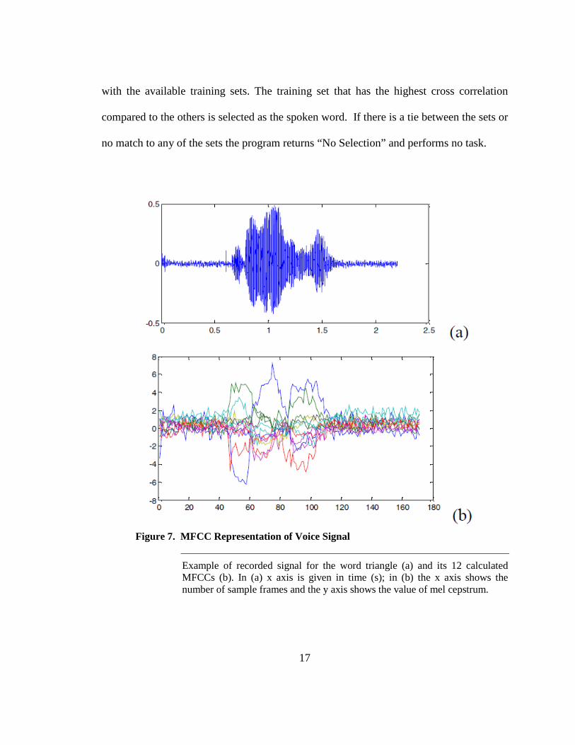
Figure 7. MFCC Representation of Voice Signal
Example of recorded signal for the word triangle (a) and its 12 calculated MFCCs (b). In (a) x axis is given in time (s); in (b) the x axis shows the number of sample frames and the y axis shows the value of mel cepstrum.
18
The mel frequency bands are positioned logarithmically on the mel scale which
approximates the human auditory system's response more closely than the linearly-spaced
frequency bands obtained directly from the FFT. To generate the MFCCs of the recorded
signals, first their Fourier transform is calculated and then the resulting log amplitude
spectrum is mapped onto the Mel scale, using triangular overlapping windows [5]. The
Discrete Cosine Transform of the list of Mel log-amplitudes is evaluated as if it were a
signal and the MFCCs are the amplitudes of the resulting spectrum (figure 7). The
following will explain computation of the MFCCs [5]:
We will use the intelligent sound implementation (ISP) to explain the
computation of MFCCs. First the recorded voice is divided into short time windows,
where we compute the discrete Fourier transform (DFT) of each time window for the
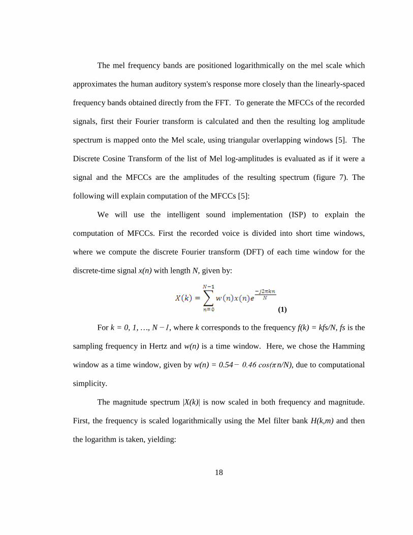
discrete-time signal x(n) with length N, given by:
(1)
For k = 0, 1, …, N −1, where k corresponds to the frequency f(k) = kfs/N, fs is the
sampling frequency in Hertz and w(n) is a time window. Here, we chose the Hamming
window as a time window, given by w(n) = 0.54 − 0.46 cos(π n/N), due to computational
simplicity.
The magnitude spectrum |X(k)| is now scaled in both frequency and magnitude.
First, the frequency is scaled logarithmically using the Mel filter bank H(k,m) and then
the logarithm is taken, yielding:
19
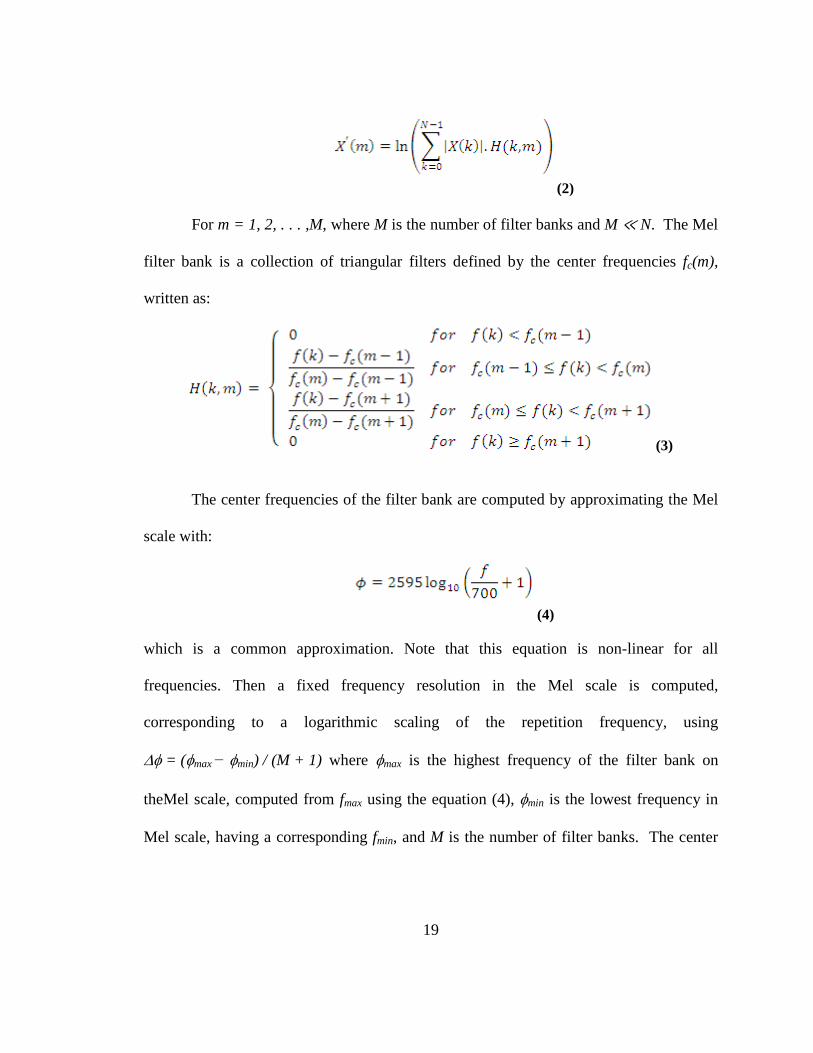
(2)
For m = 1, 2, . . . ,M, where M is the number of filter banks and M ≪ N. The Mel
filter bank is a collection of triangular filters defined by the center frequencies fc(m),
written as:
(3)
The center frequencies of the filter bank are computed by approximating the Mel
scale with:
(4)
which is a common approximation. Note that this equation is non-linear for all
frequencies. Then a fixed frequency resolution in the Mel scale is computed,
corresponding to a logarithmic scaling of the repetition frequency, using
∆φ = (φmax − φmin) / (M + 1) where φmax is the highest frequency of the filter bank on
theMel scale, computed from fmax using the equation (4), φmin is the lowest frequency in
Mel scale, having a corresponding fmin, and M is the number of filter banks. The center

20
frequencies on the Mel scale are given by φc(m) = m•∆φ for m = 1, 2, . . . ,M. To obtain
the center frequencies in Hertz, we apply the inverse of equation (4), given by:
(5)
which are inserted into equation (3) to give the Mel filter bank. Finally, the MFCCs are
obtained by computing the discrete cosine transform (DCT) of X′(m) using:
(6)
for l = 1, 2, . . . ,M, where c(l) is the lth MFCC.
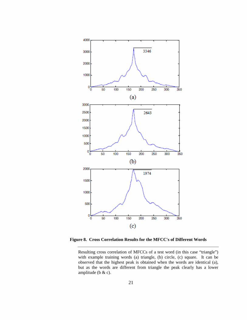
The MFCCs of the spoken command are compared with the ones in the training
sets via cross correlation. When two sets of MFCCs are cross correlated with each other
the result is a set twice the size of the original sets with multiple possible peaks at the
center. If the signals are somewhat similar a relatively large peak is distinguished at the
center of the signal. While comparing the cross correlation of the recorded command to
the training set in each test the largest peak produced by the cross correlation with circle,
square and triangle are compared with each other and the one with the largest peak is
taken as the spoken word. Figure 8 shows the result of one test done with the sample test.
They are the largest peak resulted from the cross correlation of MFCCs from triangle
with circle, square and triangle. It is observed that the cross correlation of MFCCs of
word triangle with triangle produces a larger peak compared to the cross correlation with
circle and square.
21
Figure 8. Cross Correlation Results for the MFCC's of Different Words
Resulting cross correlation of MFCCs of a test word (in this case “triangle”) with example training words (a) triangle, (b) circle, (c) square. It can be observed that the highest peak is obtained when the words are identical (a), but as the words are different from triangle the peak clearly has a lower amplitude (b & c).
22
This method was tested by several speakers in our laboratories. We present here
the results for a single male speaker. The algorithm was evaluated in a low ambient noise
environment by the same speaker. The algorithm was tested for a total of 100 times,
where each command was spoken 25 times and for the last 25 times noise and other
words were used to check “No Selection” feature of the system. This particular test
resulted in 99% accuracy; numerical results are shown in table 5.
Table 5. Accuracy of MFCC based speech recognition for GMU Neurot
Spoken Word
# of Matches to Accuracy Circle Square Triangle NS Circle 24 1 0 0 96% Square 0 25 0 0 100%
Triangle 0 0 25 0 100% NS* 0 0 0 25 100%
* NS = No Selection 2.2. LabVIEW Environment
Speech recognition for powered wheelchairs was farther tested and analyzed
using different projects utilizing the Microsoft’s Speech SDK 5.1 in LabVIEW
environment. Speech SDK 5.1 by Microsoft features great set of The Speech Application
Programming Interface (SAPI) for speech recognition and speech synthesis within
Windows applications.
i. Voice Activated RC Car
The voice activated RC car was a simple startup project for testing and
familiarizing with the speech SDK. In this project the RF controller of the RC car was
23
interfaced to the computer using transistor switches operated by digital outputs of a data
acquisition device (DAQ) from National Instruments (NI). The user interface of the
program showed the recognized word and then turned on/off the appropriate switch for
the task requested. This project was successfully tested and showed that the SAPIs are
easily integrated with LabVIEW. The computer would continuously listen for the words
spoken into the microphone and a word recognized matched the predefined word set it
would perform the corresponding action. In this project the user was required to say the
keywords of “Start Listening” for the computer start the program and could perform
movements of right, left, back and forward by saying the word command. To turn off the
process keywords of “Stop Listening” could be given to prevent the program from
accidental word matching.
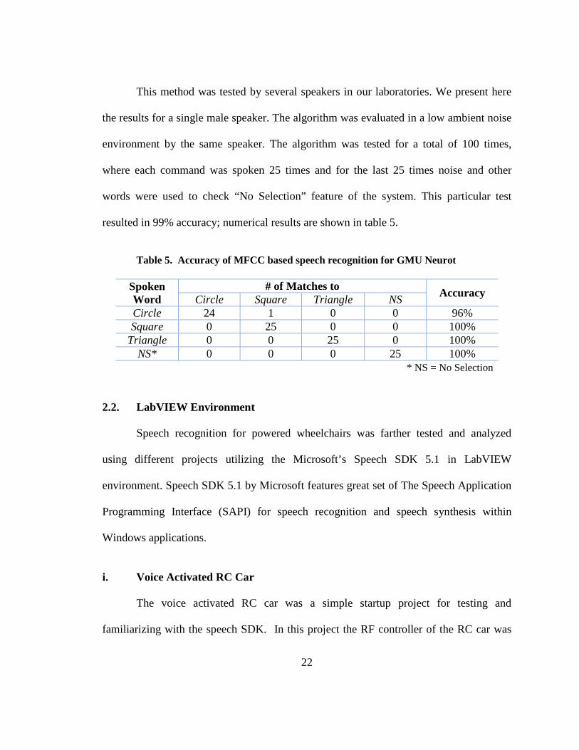
Figure 9. Voice Activated RC Car Using LabVIEW
The RC car controlled via LabVIEW and NI-DAQ via voice commands. The program running on the computer utilizes the Microsoft’s Speech SDK 5.1 for speech recognition and performs the required actions by controlling the switches attached to the physical controls of the RC car’s RF controller.
24
ii. Voice Activated Mini Lego Chair
Using Lego Mindstorms™ NXT a simple replica of a power chair was designed
which was equipped with two proximity sensors. The goal of this project was to farther
test the speech recognition capabilities for voice control of the chair and to examine the
obstacle avoidance possibilities for the future work. Since the Mindstorms’ NXT is
Bluetooth enabled the control commands for this project were sent via Bluetooth
partnership with the computer. The program designed in LabVIEW made use of
Microsoft’s Speech SDK 5.1 for speech recognition and monitored the proximity sensors
for obstacle avoidance. This project was successfully implemented and the chair was
able to stop before striking the presented obstacles.
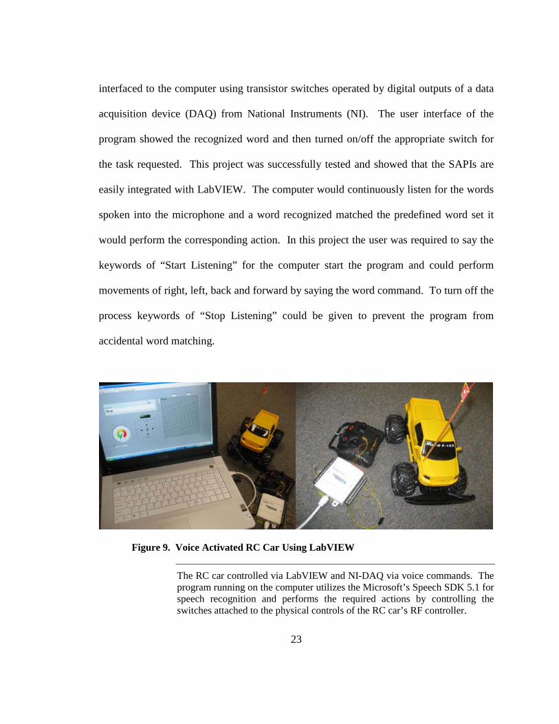
Figure 10. Voice Activated Mini Lego Chair Using LabVIEW
The Mini Lego chair designed using Lego Mindstorms™ NXT was voice controlled via Bluetooth communications. The LabVIEW program running on the computer used Microsoft Speech SDK 5.1 for speech recognition and communicated the commands to the Mini Chair using Bluetooth. The chair was capable of obstacle avoidance using its two front and back proximity sensors.
25
Chapter 3: Microcontroller Implementation for Wheelchair 3.1. Evaluation Board
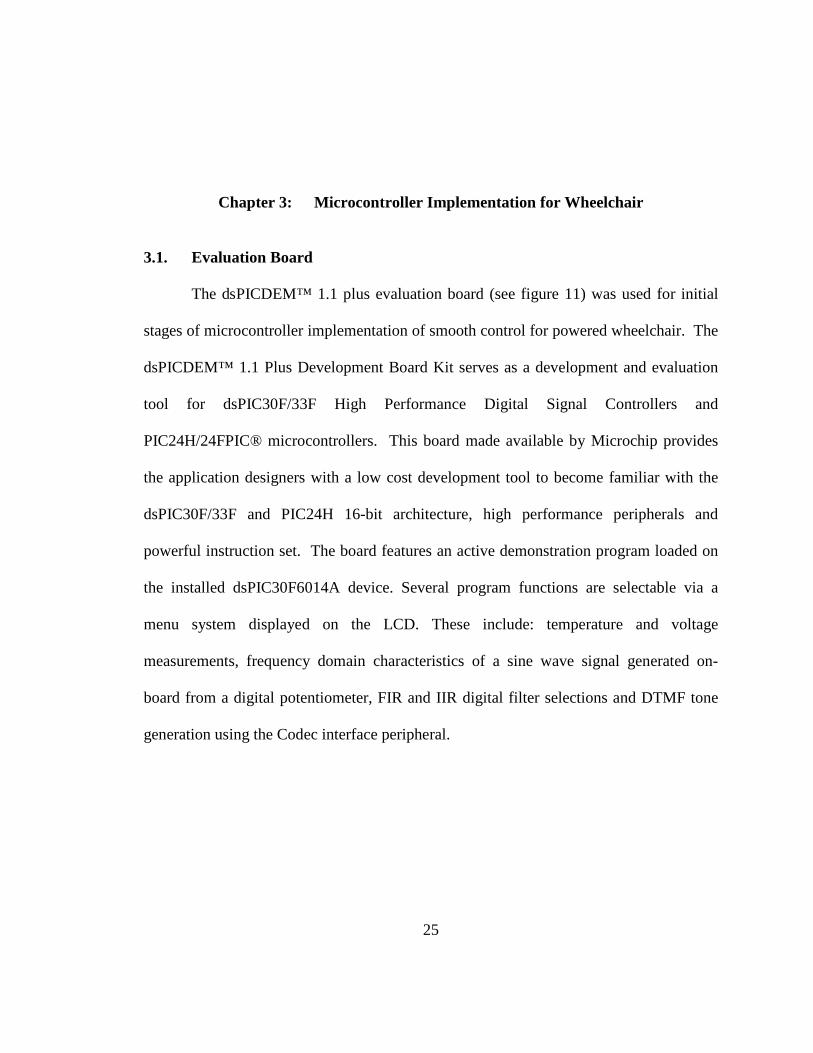
The dsPICDEM™ 1.1 plus evaluation board (see figure 11) was used for initial
stages of microcontroller implementation of smooth control for powered wheelchair. The
dsPICDEM™ 1.1 Plus Development Board Kit serves as a development and evaluation
tool for dsPIC30F/33F High Performance Digital Signal Controllers and
PIC24H/24FPIC® microcontrollers. This board made available by Microchip provides
the application designers with a low cost development tool to become familiar with the
dsPIC30F/33F and PIC24H 16-bit architecture, high performance peripherals and
powerful instruction set. The board features an active demonstration program loaded on
the installed dsPIC30F6014A device. Several program functions are selectable via a
menu system displayed on the LCD. These include: temperature and voltage
measurements, frequency domain characteristics of a sine wave signal generated on-
board from a digital potentiometer, FIR and IIR digital filter selections and DTMF tone
generation using the Codec interface peripheral.
26
Figure 11. The dsPICDEM™ Plus Development Board with MPLAB ICD 2
The dsPICDEM™ 1.1 Plus Development Board Kit serves as a development and evaluation tool for dsPIC30F/33F High Performance Digital Signal Controllers and PIC24H/24F PIC® microcontrollers.
The dsPICDEM™ 1.1 Plus Development Board has separate on-board +5V and
+3.3V regulators for VDD and AVDD with direct input from 9V, AC/DC wall adapter.
This board supports full onboard programming and debugging features with interfacing
to MPLAB ICD 2 Debugger/Programmer and includes a pad location for 80-pin TQFP
dsPIC DSC devices. The board includes multiple serial communication channels such as
27
two RS-232 communication channels, 6-pin terminal block and configuration jumper for
RS-485 and RS-422 communication on UART1 from the dsPIC DSC device and a single
CAN communication channel. This board also houses a 122 x 32 dot addressable LCD
controlled via PIC18F242 LCD controller.
The Voice Band Codec integrated with this board was one of the primary reasons
for choosing this evaluation board. A Si3000 Voice band Codec chip is included with a
jumper for selection of master or slave modes. An optional clock oscillator for Si3000
Voice band Codec can also be used for related applications. There is a 4-pin header for
the Codec Line In and Line Out with one 3.5 mm phono jack for the Codec left and right
speaker outputs and one 3.5 mm phono jack for the Codec MIC input.
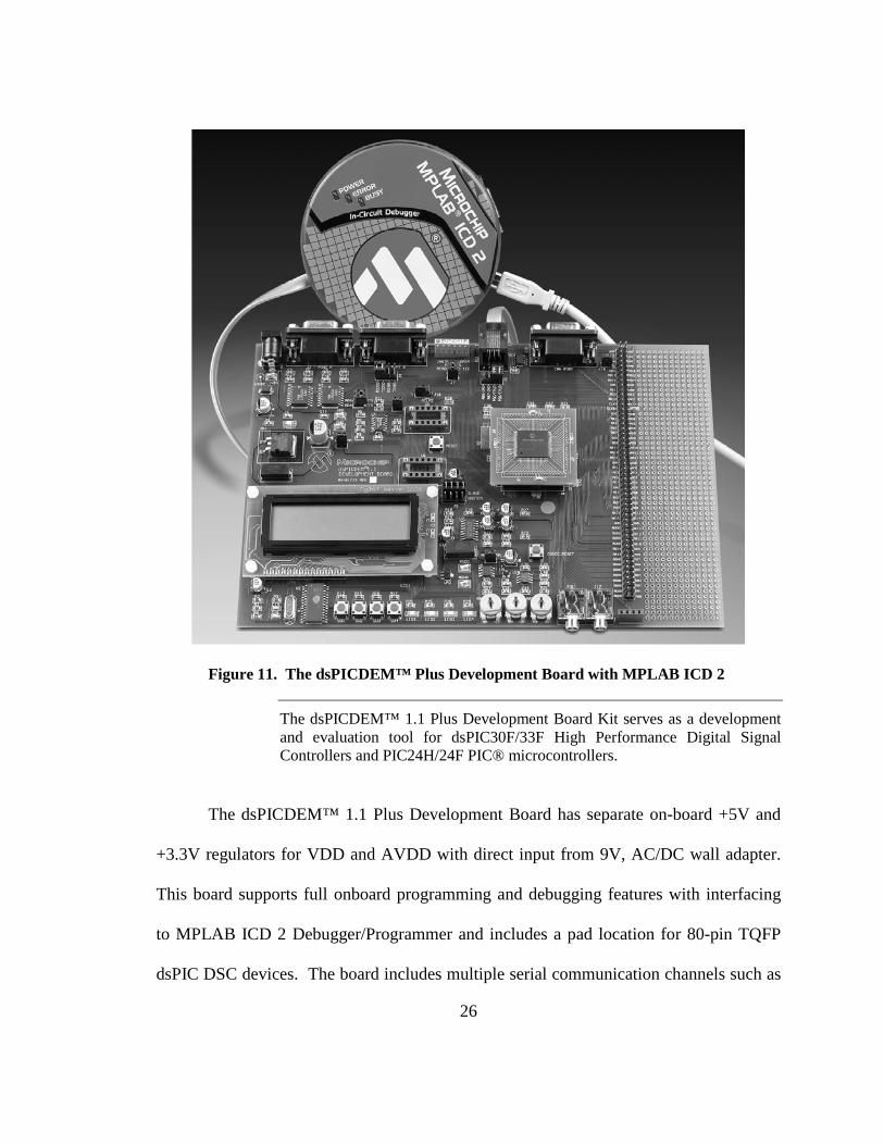
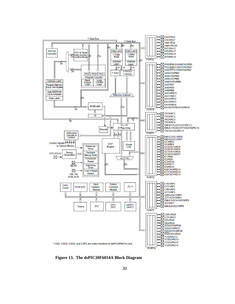
Figure 12. dsPIC30F6014A Plug-in Module
The dsPIC30F6014A PIM is designed to demonstrate the capabilities of the dsPIC30F6014A family of devices using an 80-pin PIM interface. The dsPIC30F6014A is a high-performance 16-bit Digital Signal Controller in an 80-pin TQFP package.
28
Initial programming and testing was done on the dsPICDEM™ 1.1 Plus
Development Board with the dsPIC30F6014A plug-in module (see figure 12). The
dsPIC30F6014A plug-in module (PIM) is designed to demonstrate the capabilities of the
dsPIC30F6014A family of devices using an 80-pin PIM interface. The dsPIC30F6014A
is a high-performance 16-bit Digital Signal Controller in an 80-pin TQFP package. Next
section will cover necessary information about this microcontroller.
3.2. dsPIC30F Microcontroller
The dsPIC30F6014 was used as the microcontroller for this project. The
dsPIC30F CPU module has a 16-bit (data) modified Harvard architecture with an
enhanced instruction set, including significant support for DSP. The CPU has a 24-bit
instruction word, with a variable length opcode field. The program counter (PC) is
24-bits wide and addresses up to 4M x 24 bits of user program memory space. A single
cycle instruction pre-fetch mechanism is used to help maintain throughput and provides
predictable execution. All instructions execute in a single cycle, with the exception of
instructions that change the program flow, the double-word move (MOV.D) instruction
and the table instructions. Overhead free program loop constructs are supported using the
DO and REPEAT instructions, both of which are interruptible at any point.
The dsPIC30F devices have sixteen 16-bit working registers in the programmer’s
model. Each of the working registers can act as a data, address, or address offset register.
The 16th working register (W15) operates as a software stack pointer for interrupts and
29
calls. The dsPIC30F instruction set has two classes of instructions: the MCU class of
instructions and the DSP class of instructions. These two instruction classes are
seamlessly integrated into the architecture and execute from a single execution unit. The
instruction set includes many addressing modes and was designed for optimum C
compiler efficiency.
The data space can be addressed as 32K words or 64 Kbytes and is split into two
blocks, referred to as X and Y data memory. Each memory block has its own
independent Address Generation Unit (AGU). The MCU class of instructions operates
solely through the X memory AGU, which accesses the entire memory map as one linear
data space. Certain DSP instructions operate through the X and Y AGUs to support dual
operand reads, which splits the data address space into two parts. The X and Y data
space boundary is device specific. The upper 32 Kbytes of the data space memory map
can optionally be mapped into program space at any 16K program word boundary
defined by the 8-bit Program Space Visibility Page (PSVPAG) register. The program to
data space mapping feature lets any instruction access program space as if it were data
space. Furthermore, RAM may be connected to the program memory bus on devices
with an external bus and used to extend the internal data RAM.
30
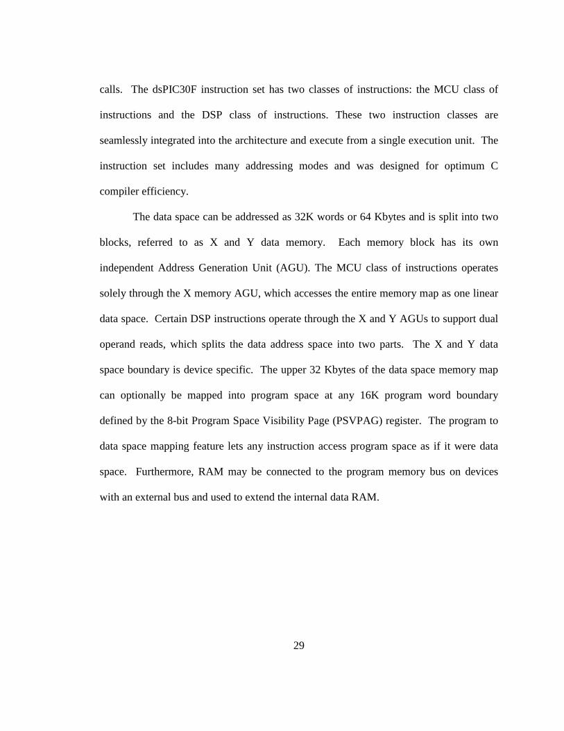
Figure 13. The dsPIC30F6014A Block Diagram

31
Overhead free circular buffers (modulo addressing) are supported in both X and Y
address spaces. The modulo addressing removes the software boundary checking
overhead for DSP algorithms. Furthermore, the X AGU circular addressing can be used
with any of the MCU class of instructions. The X AGU also supports bit-reverse
addressing to greatly simplify input or output data reordering for radix-2 FFT algorithms.
The CPU supports Inherent (no operand), Relative, Literal, Memory Direct,
Register Direct and Register Indirect Addressing modes. Each instruction is associated
with a predefined addressing mode group depending upon its functional requirements.
As many as 6 addressing modes are supported for each instruction. For most instructions,
the dsPIC30F is capable of executing a data (or program data) memory read, a working
register (data) read, a data memory write and a program (instruction) memory read per
instruction cycle. As a result, 3 operand instructions can be supported, allowing A+B=C
operations to be executed in a single cycle.
The DSP engine features a high speed, 17-bit by 17-bit multiplier, a 40-bit ALU,
two 40-bit saturating accumulators and a 40-bit bi-directional barrel shifter. The barrel
shifter is capable of shifting a 40-bit value up to 15 bits right, or up to 16 bits left, in a
single cycle. The DSP instructions operate seamlessly with all other instructions and
have been designed for optimal real-time performance. The MAC instruction and other
associated instructions can concurrently fetch two data operands from memory while
multiplying two W registers. This requires that the data space be split for these
instructions and linear for all others. This is achieved in a transparent and flexible
manner through dedicating certain working registers to each address space. The
32
dsPIC30F has a vectored exception scheme with up to 8 sources of non-maskable traps
and 54 interrupt sources. Each interrupt source can be assigned to one of seven priority
levels.
3.3. Designed Board i. Speech Recognition Engine
The dsPIC30F Speech Recognition Library was used as the speech recognition
engine of this project. The dsPIC30F Speech Recognition Library allows the
incorporation of speech recognition in an embedded application program running on a
dsPIC30F device. A predefined list of words controls the application with only a modest
amount of RAM and program memory. The word list is created with the dsPIC30F
Speech Recognition Library Word Library Builder. The Word Library Builder is a PC-
based program that lets users select and implement the user interface vocabulary. The
Word Library Builder provides the supplemental files needed by the user application to
define the allowable words, the Library Keyword, the word recognition features for the
Vector Codebook and the Hidden Markov Model (HMM) data files for each library word.
The dsPIC30F Speech Recognition Library provides an audio interface to a user’s
application program, allowing the user to control the application by uttering discrete
words that are contained in a predefined word library. The words chosen for the library
are specifically relevant to the interaction between the application program and the user.
Upon recognition of a word, the application program takes an appropriate action as
shown in figure 14.

33
Figure 14. Overview of Speech Recognition
The Speech Recognition Library provides isolated, speaker independent word recognition of US English. It allows a user to control an application through a set of fixed, voice commands. The library has already been pre-trained by a demographic cross-section of male and female US English speakers. Conveniently, no training is required for end-users of the product.
The dsPIC30F Speech Recognition Library uses a recognition algorithm based on
discrete Hidden Markov Model (HMM) of words (one HMM model for each word in an
application word library). A word spoken through a microphone connected to the
dsPIC30F application board is analyzed on a frame-by-frame basis using RASTA-PLP
algorithm and quantized into feature vectors of sound characteristics against a vector
codebook. The quantized feature vectors are then examined to determine what word
HMM model they most closely match. The dsPIC30F Speech Recognition Library
operates in both clear (free of noise) and noisy conditions. Background interference can
include white noise, office noise and passenger compartment noise components in any

34
mixture. Total signal-to-noise ratio (SNR) should be no less than 15 dB. A signal level
above the noise threshold is presumed to be an incoming word.
The dsPIC30F Speech Recognition Library can operate with a word library of up
to 100 words. The word library is built around a keyword that is readily interpreted.
Depending on the operating mode used, this keyword can be used to self-test the library
and to trigger a recognition session. Successful recognition requires the words to be
separated by a pause of at least one-half second but less than some specified period
(normally programmed for five seconds). After a pause that times out, a new recognition
session must be started. Optionally, the operating mode can be set to disable self-testing
and/or keyword activation. When keyword activation is disabled, there is no timeout.
Words must only be separated by at least 500 milliseconds.
Figure 15 is a simplified flow diagram of the dsPIC30F Speech Recognition
Library operation. When the application board is powered up, the library is initialized,
which also establishes the operating mode. The operating mode determines if a self-test is
run and if the keyword is used to activate a recognition session. The self-test processes a
sample utterance (stored in memory) of the library keyword. If the self-test fails, the
diagnostic routine returns an error code indicating that appropriate remedial action must
be taken. For example, it may be necessary to verify the build of the application. If the
self-test is successful, the library estimates a baseline noise level and enters either the
Keyword Search mode or the Listen mode, depending on whether keyword activation is
enabled.

35
Figure 15. Overview of Speech Recognition Flow Diagram

36
If keyword activation is enabled, the library remains in the Keyword Search mode
until the user articulates the keyword. In this mode, the keyword must be recognized
before any further speech recognition can take place. This functionality is important in
applications where user security is an issue. For example, a user might be required to
articulate a specific word such as “security” followed by a series of numbers to gain
access to something. Once the keyword is recognized, the library enters the Listen mode.
In this mode the library must receive a new word within the specified Listen Window
timeout period (normally about 5 seconds). If the timeout period elapses without a new
word, and keyword activation is enabled, the library reverts to the Keyword Search mode.
The user must then rearticulate the keyword to start a new recognition session. If
keyword activation is not enabled, the library immediately enters the Listen mode. In this
mode, the library attempts to recognize any incoming word. Upon successful recognition
of the first word, the library notifies the user application and listens for the next word.
ii. Humming Detection Technique
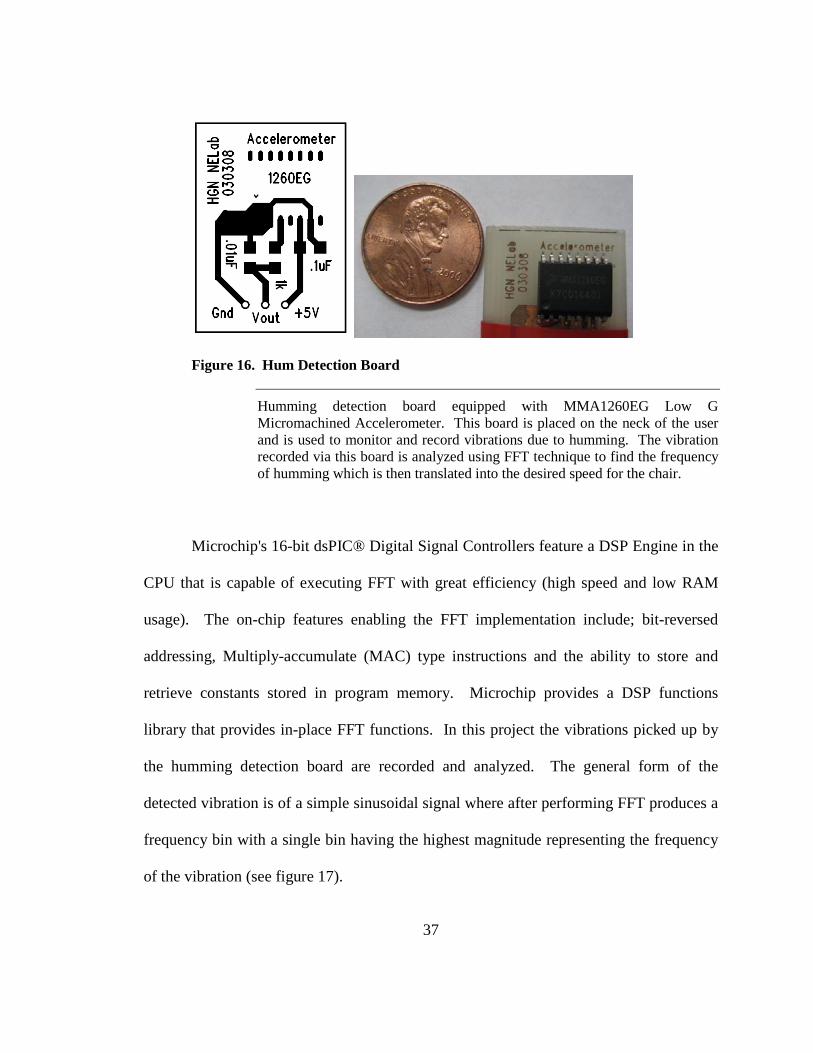
The innovative way of control in this project through humming required the
detection of humming frequency and for this matter a small board equipped with an
accelerometer was designed to pick up the vibration due to the humming. Figure 16
shows the designed board with the accelerometer. The analog output of this
accelerometer was captured using the dsPIC and converted to digital signals. Using a set
of 512 samples from these data points the frequency of humming is established using Fast
Fourier Transform (FFT).
37
Figure 16. Hum Detection Board
Humming detection board equipped with MMA1260EG Low G Micromachined Accelerometer. This board is placed on the neck of the user and is used to monitor and record vibrations due to humming. The vibration recorded via this board is analyzed using FFT technique to find the frequency of humming which is then translated into the desired speed for the chair.
Microchip's 16-bit dsPIC® Digital Signal Controllers feature a DSP Engine in the
CPU that is capable of executing FFT with great efficiency (high speed and low RAM
usage). The on-chip features enabling the FFT implementation include; bit-reversed
addressing, Multiply-accumulate (MAC) type instructions and the ability to store and
retrieve constants stored in program memory. Microchip provides a DSP functions
library that provides in-place FFT functions. In this project the vibrations picked up by
the humming detection board are recorded and analyzed. The general form of the
detected vibration is of a simple sinusoidal signal where after performing FFT produces a
frequency bin with a single bin having the highest magnitude representing the frequency
of the vibration (see figure 17).
38
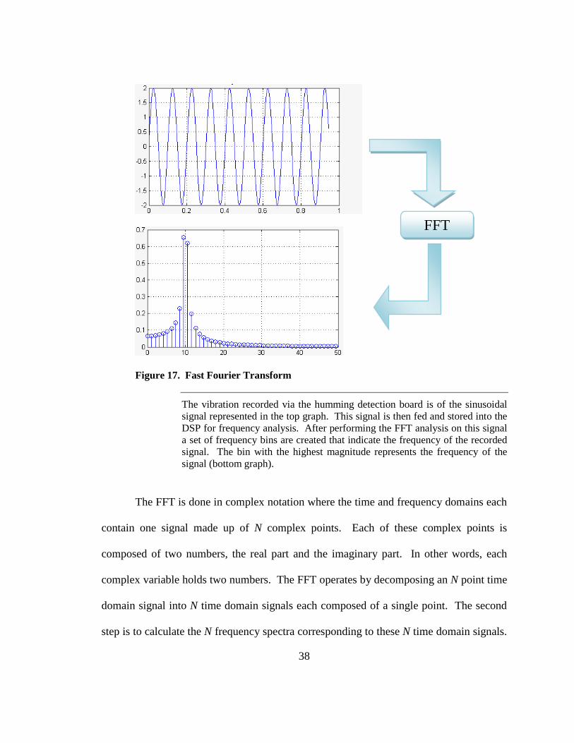
Figure 17. Fast Fourier Transform
The vibration recorded via the humming detection board is of the sinusoidal signal represented in the top graph. This signal is then fed and stored into the DSP for frequency analysis. After performing the FFT analysis on this signal a set of frequency bins are created that indicate the frequency of the recorded signal. The bin with the highest magnitude represents the frequency of the signal (bottom graph).
The FFT is done in complex notation where the time and frequency domains each
contain one signal made up of N complex points. Each of these complex points is
composed of two numbers, the real part and the imaginary part. In other words, each
complex variable holds two numbers. The FFT operates by decomposing an N point time
domain signal into N time domain signals each composed of a single point. The second
step is to calculate the N frequency spectra corresponding to these N time domain signals.
FFT
39
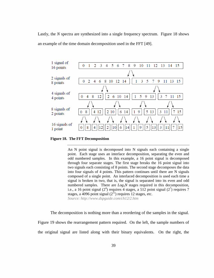
Lastly, the N spectra are synthesized into a single frequency spectrum. Figure 18 shows
an example of the time domain decomposition used in the FFT [49].
Figure 18. The FFT Decomposition
An N point signal is decomposed into N signals each containing a single point. Each stage uses an interlace decomposition, separating the even and odd numbered samples. In this example, a 16 point signal is decomposed through four separate stages. The first stage breaks the 16 point signal into two signals each consisting of 8 points. The second stage decomposes the data into four signals of 4 points. This pattern continues until there are N signals composed of a single point. An interlaced decomposition is used each time a signal is broken in two, that is, the signal is separated into its even and odd numbered samples. There are Log2N stages required in this decomposition, i.e., a 16 point signal (24) requires 4 stages, a 512 point signal (27) requires 7 stages, a 4096 point signal (212) requires 12 stages, etc. Source: http://www.dspguide.com/ch12/2.htm
The decomposition is nothing more than a reordering of the samples in the signal.
Figure 19 shows the rearrangement pattern required. On the left, the sample numbers of
the original signal are listed along with their binary equivalents. On the right, the
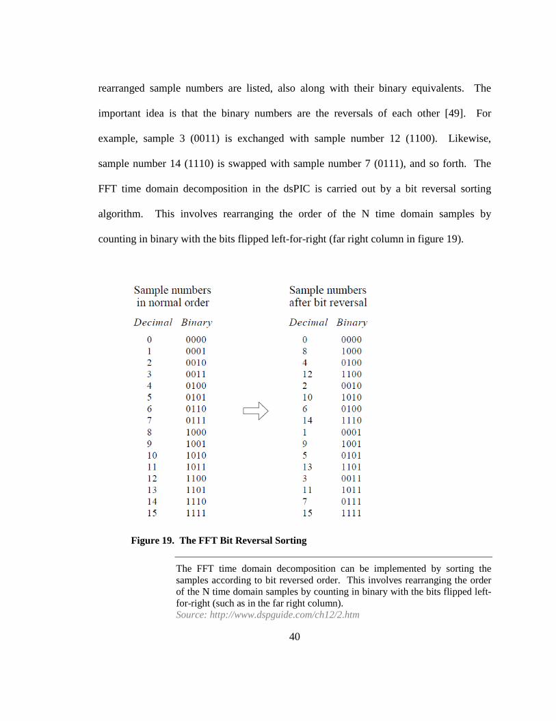
40
rearranged sample numbers are listed, also along with their binary equivalents. The
important idea is that the binary numbers are the reversals of each other [49]. For
example, sample 3 (0011) is exchanged with sample number 12 (1100). Likewise,
sample number 14 (1110) is swapped with sample number 7 (0111), and so forth. The
FFT time domain decomposition in the dsPIC is carried out by a bit reversal sorting
algorithm. This involves rearranging the order of the N time domain samples by
counting in binary with the bits flipped left-for-right (far right column in figure 19).
Figure 19. The FFT Bit Reversal Sorting
The FFT time domain decomposition can be implemented by sorting the samples according to bit reversed order. This involves rearranging the order of the N time domain samples by counting in binary with the bits flipped left-for-right (such as in the far right column). Source: http://www.dspguide.com/ch12/2.htm
41
The next step in the FFT algorithm is to find the frequency spectra of the 1 point
time domain signals, which is equal to itself. This means that nothing is required to do
this step, but each of the 1 point signals is now a frequency spectrum, and not a time
domain signal [46]. The last step in the FFT is to combine the N frequency spectra in the
exact reverse order that the time domain decomposition took place. In the first stage, 16
frequency spectra (1 point each) are synthesized into 8 frequency spectra (2 points each).
In the second stage, the 8 frequency spectra (2 points each) are synthesized into 4
frequency spectra (4 points each), and so on. The last stage results in the output of the
FFT, a 16 point frequency spectrum.
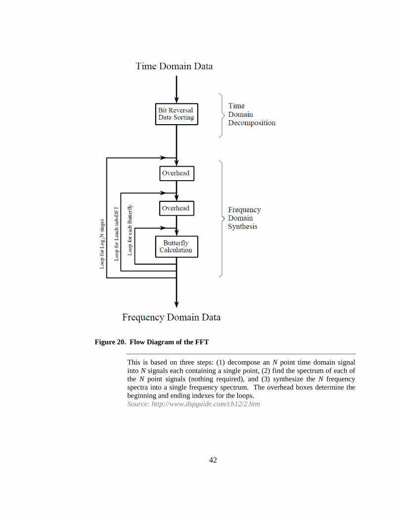
Figure 20 shows the structure of the entire FFT process used in the dsPIC. The
time domain decomposition is accomplished with a bit reversal sorting algorithm.
Transforming the decomposed data into the frequency domain involves nothing and
therefore does not appear in the figure. The frequency domain synthesis requires three
loops. The outer loop runs through the Log2N stages (i.e., each level in figure 18, starting
from the bottom and moving to the top). The middle loop moves through each of the
individual frequency spectra in the stage being worked on (i.e., each of the boxes on any
one level in figure 18). The innermost loop uses the butterfly to calculate the points in
each frequency spectra (i.e., looping through the samples inside any one box in figure
18).
42
Figure 20. Flow Diagram of the FFT
This is based on three steps: (1) decompose an N point time domain signal into N signals each containing a single point, (2) find the spectrum of each of the N point signals (nothing required), and (3) synthesize the N frequency spectra into a single frequency spectrum. The overhead boxes determine the beginning and ending indexes for the loops. Source: http://www.dspguide.com/ch12/2.htm
43
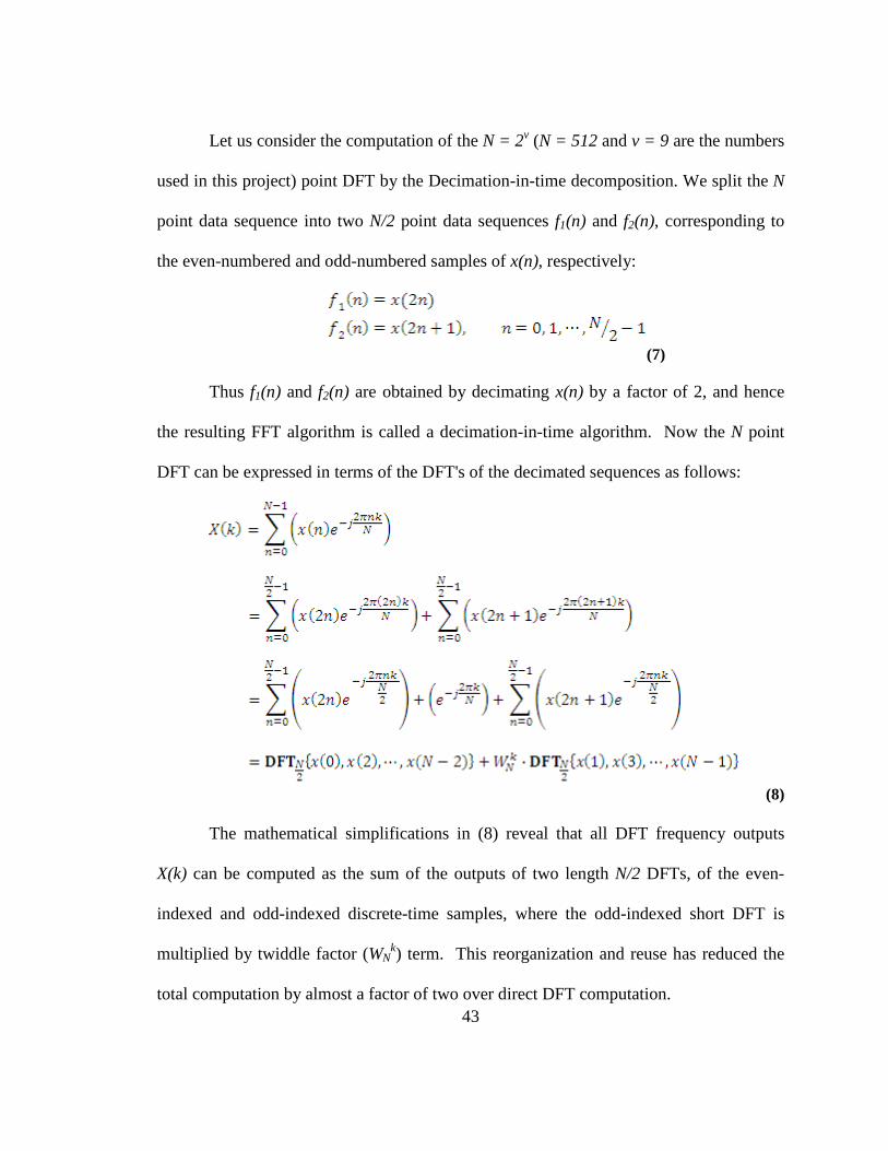
Let us consider the computation of the N = 2v (N = 512 and v = 9 are the numbers
used in this project) point DFT by the Decimation-in-time decomposition. We split the N
point data sequence into two N/2 point data sequences f1(n) and f2(n), corresponding to
the even-numbered and odd-numbered samples of x(n), respectively:
(7)
Thus f1(n) and f2(n) are obtained by decimating x(n) by a factor of 2, and hence
the resulting FFT algorithm is called a decimation-in-time algorithm. Now the N point
DFT can be expressed in terms of the DFT's of the decimated sequences as follows:
(8)
The mathematical simplifications in (8) reveal that all DFT frequency outputs
X(k) can be computed as the sum of the outputs of two length N/2 DFTs, of the even-
indexed and odd-indexed discrete-time samples, where the odd-indexed short DFT is
multiplied by twiddle factor (WNk) term. This reorganization and reuse has reduced the
total computation by almost a factor of two over direct DFT computation.
44
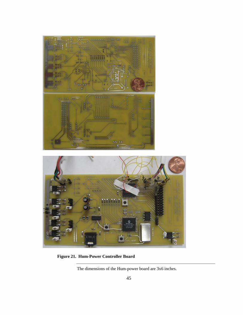
iii. Powered Wheelchair Interface
The printed circuit board (PCB) in figure 21 was designed and fabricated to
interface the controller with the powered wheelchair. This PCB houses two dsPIC30F
microcontrollers dedicated for speech recognition and FFT analysis. The dsPIC
performing the speech recognition is connected to the Si3000 voice CODEC for sampling
the input voice from its MIC input. Other dsPIC performing FFT on the accelerometer
data is directly connected to the speech recognition dsPIC via 8 digital inputs (for
detected voice commands) and is also capable of reading other sensory inputs such as
distance sensors. A digital-to-analog converter is used to connect this controller to the
joystick of the powered wheelchair. The direction commands from the joystick to the
wheelchair’s unit are controlled over 2 analog inputs. These inputs are bypassed from the
joystick with the inputs from our controller. Out of these two wires one is used to control
the movement in forward/backward direction and the other is used to control the right/left
direction of movement. To keep the chair in the neutral mode both of these wires must
be at +2.5 V. Voltage above this threshold will result in forward/right movement and the
voltage below this threshold results in backward/left movement. Deviation of ±1.5 V is
allowed on these lines and the speed of the movement is proportional to the amount of
voltage deviation from +2.5 V.
45
Figure 21. Hum-Power Controller Board
The dimensions of the Hum-power board are 3x6 inches.

46
Figure 22 shows the block diagram of the current Hum-Power prototype. The
touch screen display is currently used only as user interface and is not used to collect
input from the user. This controller runs on the 15 V power coming to the chair’s
joystick and is turned on as soon as the chair is turned on using the joystick. Then the
controller runs an initial self test for the speech recognition and requests the user to speak
a keyword.
Smooth Control Board
SpeechRecognition Engine
HummingFrequency Detector
(FFT)
Controller(Joystick Interface)
Voice Commands
Accelerometer
Distance sensors
Joystick(Wheel Chair)
Touch screen display(user interface)
Figure 22. Block Diagram of the Hum-Power Controller
The Hum-Power board is consisted of three major modules. Speech recognition engine which is included in one of the dsPIC’s on the board and humming frequency detection and FFT performed on a separate dsPIC which is connected to the joystick controller interface and the touch screen display for user interface. This board is powered via the joystick’s 15 V power and controls the joystick via 2 wires for back/forward and right/left.
Figures 23-25 show the schematics used for prototyping the Hum-power
controller. There are three main components in the design of this controller: dsPIC1
dedicated for speech recognition, dsPIC2 for performing FFT and communication with
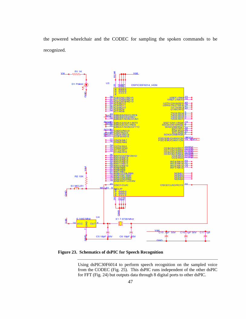
47
the powered wheelchair and the CODEC for sampling the spoken commands to be
recognized.
Figure 23. Schematics of dsPIC for Speech Recognition
Using dsPIC30F6014 to perform speech recognition on the sampled voice from the CODEC (Fig. 25). This dsPIC runs independent of the other dsPIC for FFT (Fig. 24) but outputs data through 8 digital ports to other dsPIC.
48
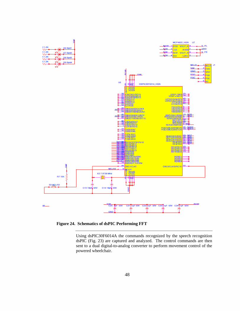
Figure 24. Schematics of dsPIC Performing FFT
Using dsPIC30F6014A the commands recognized by the speech recognition dsPIC (Fig. 23) are captured and analyzed. The control commands are then sent to a dual digital-to-analog converter to perform movement control of the powered wheelchair.
49
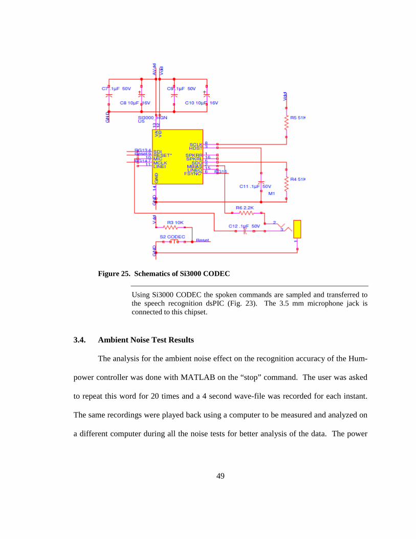
Figure 25. Schematics of Si3000 CODEC
Using Si3000 CODEC the spoken commands are sampled and transferred to the speech recognition dsPIC (Fig. 23). The 3.5 mm microphone jack is connected to this chipset.
3.4. Ambient Noise Test Results
The analysis for the ambient noise effect on the recognition accuracy of the Hum-
power controller was done with MATLAB on the “stop” command. The user was asked
to repeat this word for 20 times and a 4 second wave-file was recorded for each instant.
The same recordings were played back using a computer to be measured and analyzed on
a different computer during all the noise tests for better analysis of the data. The power

50
of these signals in the presence of no added white Gaussian noise was calculated and is
plotted in figure 26.
2 4 6 8 10 12 14 16 18 20
1
1.1
1.2
1.3
1.4
1.5
1.6
1.7
x 10-5 Measured Signal Power w/o Noise
Pow
er
Figure 26. Measured Signal Power without added Noise
The word “stop” was recorded 20 times for 4 seconds in each instance. The recorded signals were in the presence of usually ambient noise without any added Gaussian white noise. The power of these signals was calculated using MATLAB. This shows that different recordings of command “stop” had different power levels given that the ambient noise was not constant at all time and that the user pronounced the word differently at different instances.
To simulate higher ambient noise a white Gaussian noise source was used (2 feet
away from the microphone) to increase the noise in the background while recording the
commands for analysis. The first recorded “stop” command was then played back for 20
times and at each instance the level of white Gaussian noise was increased by 5% from 0
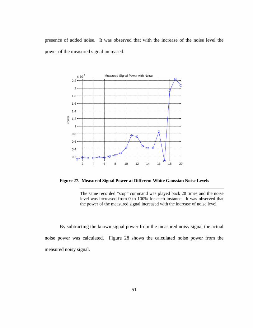
to a full 100%. Figure 27 shows the calculated power for the measured signal with the
51
presence of added noise. It was observed that with the increase of the noise level the
power of the measured signal increased.
2 4 6 8 10 12 14 16 18 20
0.2
0.4
0.6
0.8
1
1.2
1.4
1.6
1.8
2
2.2x 10
-4 Measured Signal Power with Noise
Pow
er
Figure 27. Measured Signal Power at Different White Gaussian Noise Levels
The same recorded “stop” command was played back 20 times and the noise level was increased from 0 to 100% for each instance. It was observed that the power of the measured signal increased with the increase of noise level.
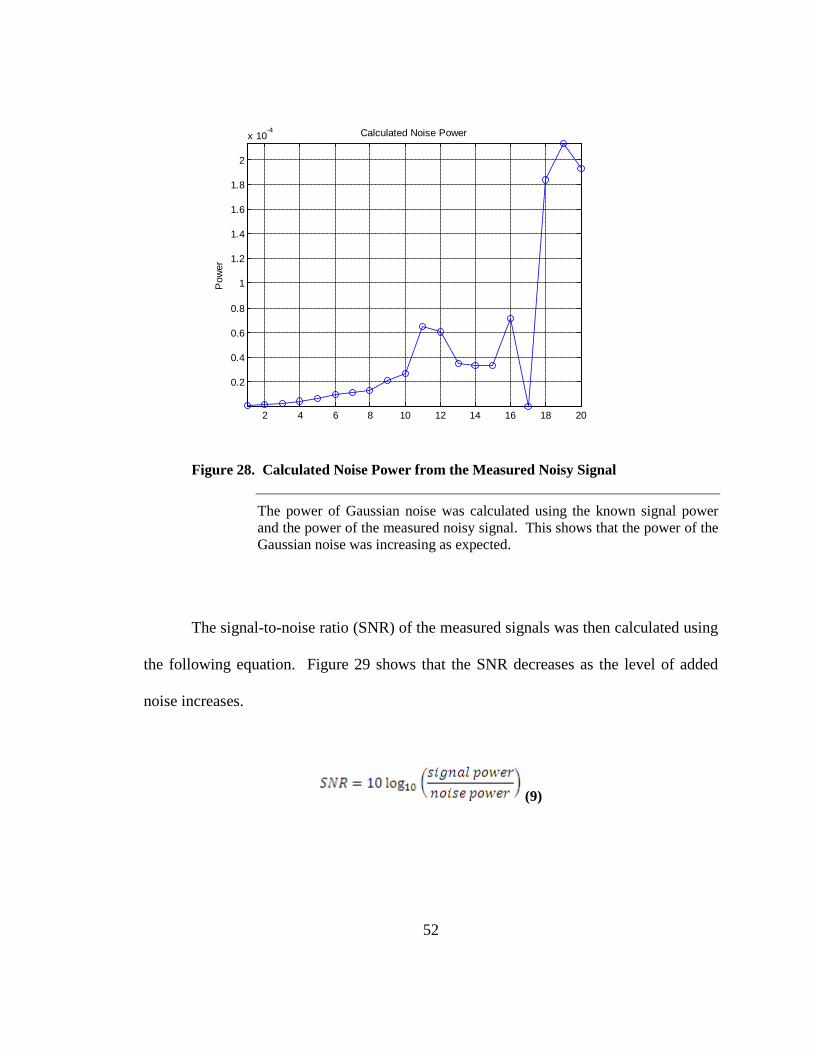
By subtracting the known signal power from the measured noisy signal the actual
noise power was calculated. Figure 28 shows the calculated noise power from the
measured noisy signal.
52
2 4 6 8 10 12 14 16 18 20
0.2
0.4
0.6
0.8
1
1.2
1.4
1.6
1.8
2
x 10-4 Calculated Noise Power
Pow
er
Figure 28. Calculated Noise Power from the Measured Noisy Signal
The power of Gaussian noise was calculated using the known signal power and the power of the measured noisy signal. This shows that the power of the Gaussian noise was increasing as expected.
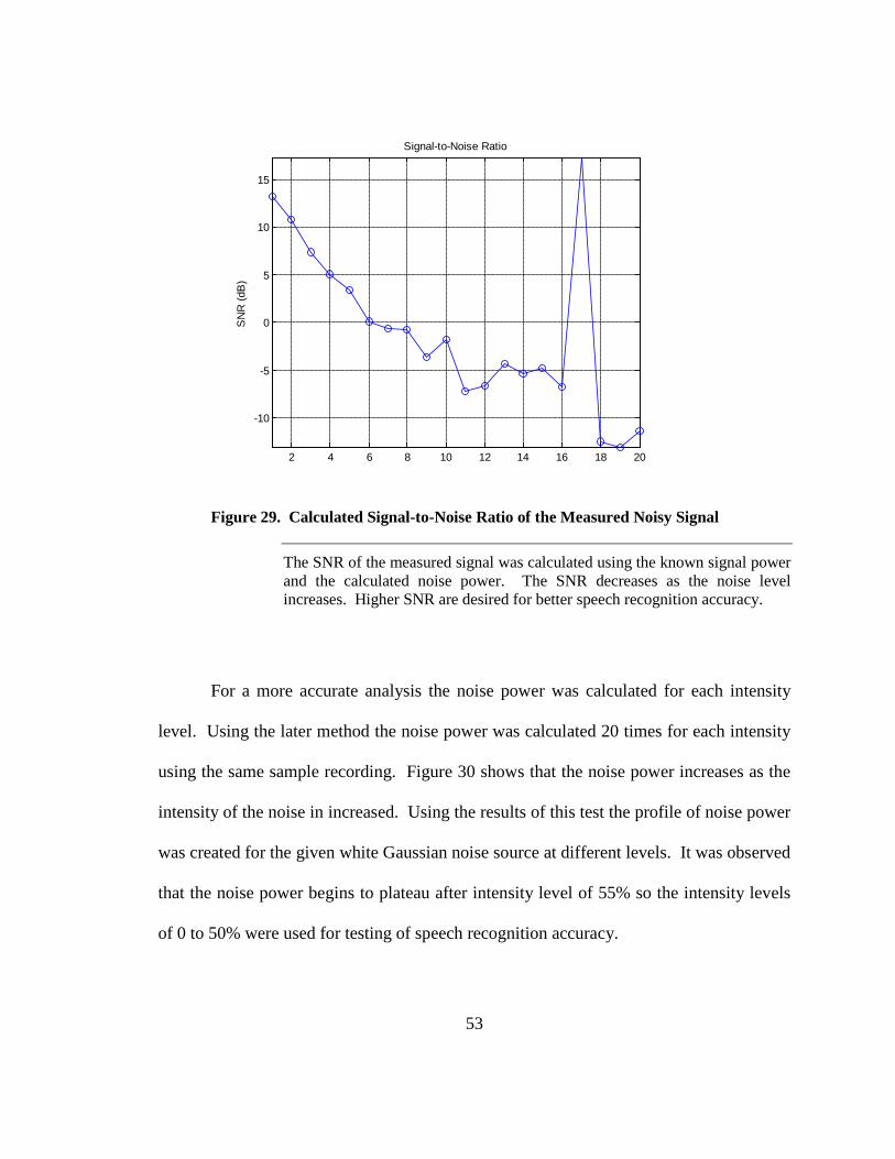
The signal-to-noise ratio (SNR) of the measured signals was then calculated using
the following equation. Figure 29 shows that the SNR decreases as the level of added
noise increases.
(9)
53
2 4 6 8 10 12 14 16 18 20
-10
-5
0
5
10
15
Signal-to-Noise Ratio
SN
R (d
B)
Figure 29. Calculated Signal-to-Noise Ratio of the Measured Noisy Signal
The SNR of the measured signal was calculated using the known signal power and the calculated noise power. The SNR decreases as the noise level increases. Higher SNR are desired for better speech recognition accuracy.
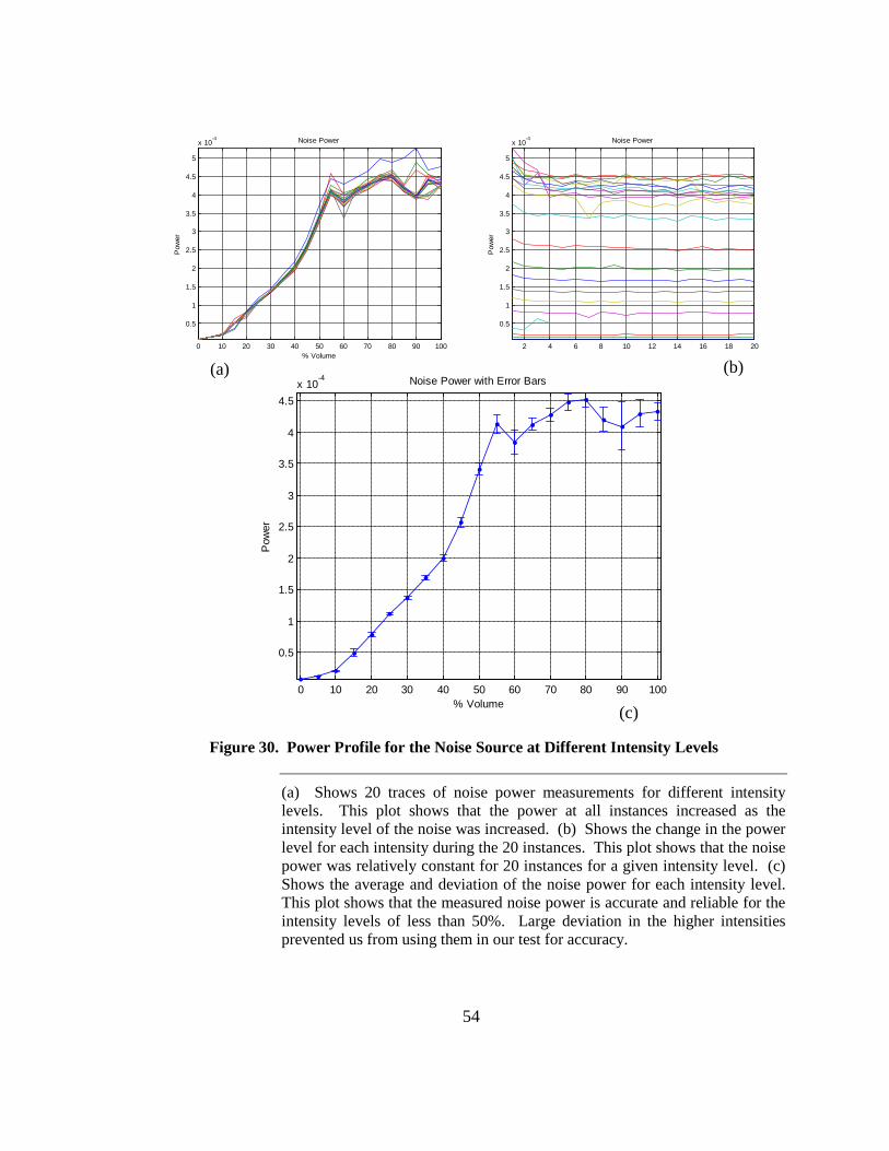
For a more accurate analysis the noise power was calculated for each intensity
level. Using the later method the noise power was calculated 20 times for each intensity
using the same sample recording. Figure 30 shows that the noise power increases as the
intensity of the noise in increased. Using the results of this test the profile of noise power
was created for the given white Gaussian noise source at different levels. It was observed
that the noise power begins to plateau after intensity level of 55% so the intensity levels
of 0 to 50% were used for testing of speech recognition accuracy.
54
0 10 20 30 40 50 60 70 80 90 100
0.5
1
1.5
2
2.5
3
3.5
4
4.5
5
x 10-4 Noise Power
Pow
er
% Volume2 4 6 8 10 12 14 16 18 20
0.5
1
1.5
2
2.5
3
3.5
4
4.5
5
x 10-4 Noise Power
Pow
er
0 10 20 30 40 50 60 70 80 90 100
0.5
1
1.5
2
2.5
3
3.5
4
4.5x 10
-4 Noise Power with Error Bars
Pow
er
% Volume
Figure 30. Power Profile for the Noise Source at Different Intensity Levels
(a) Shows 20 traces of noise power measurements for different intensity levels. This plot shows that the power at all instances increased as the intensity level of the noise was increased. (b) Shows the change in the power level for each intensity during the 20 instances. This plot shows that the noise power was relatively constant for 20 instances for a given intensity level. (c) Shows the average and deviation of the noise power for each intensity level. This plot shows that the measured noise power is accurate and reliable for the intensity levels of less than 50%. Large deviation in the higher intensities prevented us from using them in our test for accuracy.
(a) (b)
(c)
55
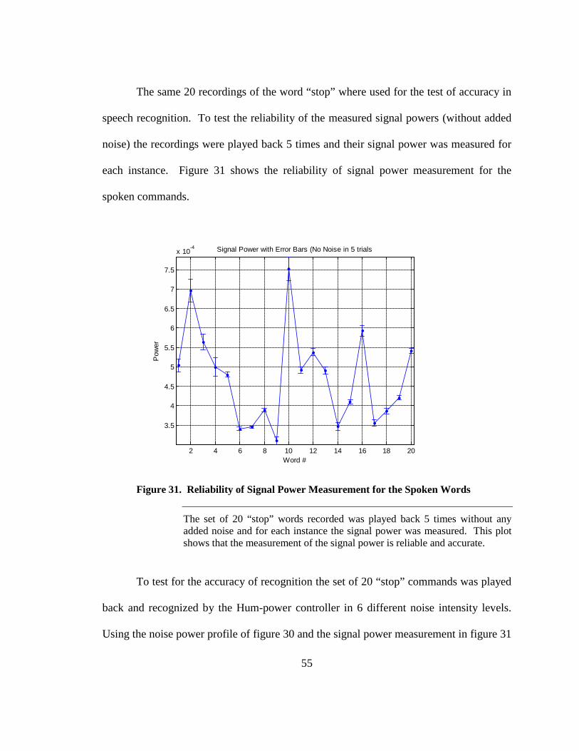
The same 20 recordings of the word “stop” where used for the test of accuracy in
speech recognition. To test the reliability of the measured signal powers (without added
noise) the recordings were played back 5 times and their signal power was measured for
each instance. Figure 31 shows the reliability of signal power measurement for the
spoken commands.
2 4 6 8 10 12 14 16 18 20
3.5
4
4.5
5
5.5
6
6.5
7
7.5
x 10-4 Signal Power with Error Bars (No Noise in 5 trials
Pow
er
Word #
Figure 31. Reliability of Signal Power Measurement for the Spoken Words
The set of 20 “stop” words recorded was played back 5 times without any added noise and for each instance the signal power was measured. This plot shows that the measurement of the signal power is reliable and accurate.
To test for the accuracy of recognition the set of 20 “stop” commands was played
back and recognized by the Hum-power controller in 6 different noise intensity levels.
Using the noise power profile of figure 30 and the signal power measurement in figure 31

56
the SNR of recognized words was calculated. Figure 32 shows the SNR of each
recognized word at different noise intensity levels with the percent accuracy of the
speech recognition at different SNR levels.
2 4 6 8 10 12 14 16 18 20
-5
0
5
10
15
20
Signal-to-Noise Ratio
SN
R (d
B)
Word #
Figure 32. Speech Recognition Accuracy at Different SNR Levels
(a) Shows the SNR of the tested commands for 6 different noise levels. (b) Shows the present accuracy of the speech recognition for an average SNR level recorded.
(a)
(b)
57
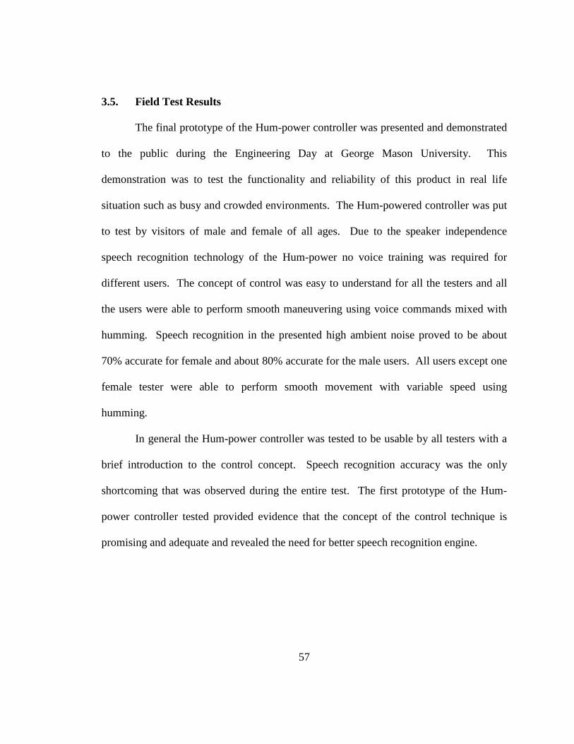
3.5. Field Test Results
The final prototype of the Hum-power controller was presented and demonstrated
to the public during the Engineering Day at George Mason University. This
demonstration was to test the functionality and reliability of this product in real life
situation such as busy and crowded environments. The Hum-powered controller was put
to test by visitors of male and female of all ages. Due to the speaker independence
speech recognition technology of the Hum-power no voice training was required for
different users. The concept of control was easy to understand for all the testers and all
the users were able to perform smooth maneuvering using voice commands mixed with
humming. Speech recognition in the presented high ambient noise proved to be about
70% accurate for female and about 80% accurate for the male users. All users except one
female tester were able to perform smooth movement with variable speed using
humming.
In general the Hum-power controller was tested to be usable by all testers with a
brief introduction to the control concept. Speech recognition accuracy was the only
shortcoming that was observed during the entire test. The first prototype of the Hum-
power controller tested provided evidence that the concept of the control technique is
promising and adequate and revealed the need for better speech recognition engine.
58
Chapter 4: Discussion 4.1. What Was Achieved in This Thesis
In this thesis a new and innovative controller interface for powered wheelchairs
was investigated, proposed, and designed. The prototype of the Hum-Power controller
was implemented and successfully tested on the Invacare’s Storm TDX5 (mid-wheel
drive power chair) donated to us by East Coast Rehab, LLC. Hum-Power controller
enables its users to control their powered wheelchairs via voice commands and provides
them with accurate and smooth control over the speed if needed using humming. This
controller is capable of translating the user’s frequency of the humming to their desired
speed of movement for maneuvering in environments that required precise control. This
controller can be easily interfaced with the joystick available on the user’s current
wheelchair. The ambient noise testing for speech recognition proves near 90% accuracy
in signal to noise ratio (SNR) of about 15dB. This working product of Hum-Power
controller showed that such controllers with speech and hum recognition are possible to
be implemented and marketed as successful and innovative new powered wheelchair
controller.
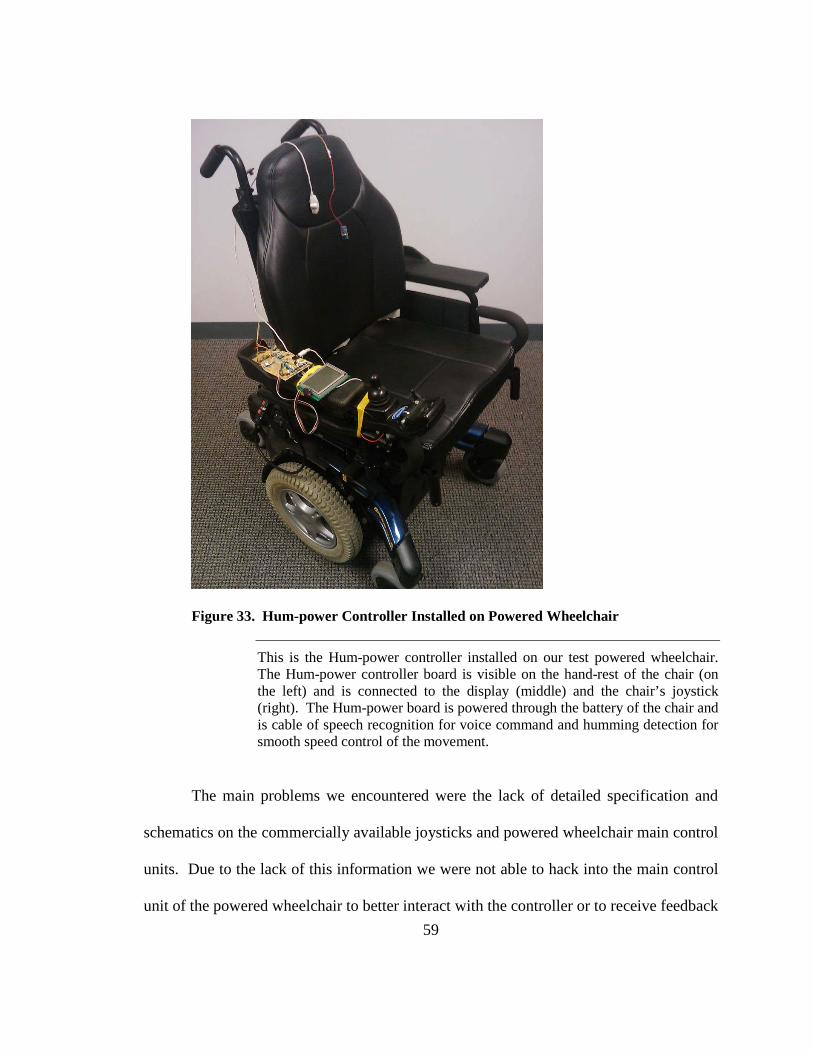
59
Figure 33. Hum-power Controller Installed on Powered Wheelchair
This is the Hum-power controller installed on our test powered wheelchair. The Hum-power controller board is visible on the hand-rest of the chair (on the left) and is connected to the display (middle) and the chair’s joystick (right). The Hum-power board is powered through the battery of the chair and is cable of speech recognition for voice command and humming detection for smooth speed control of the movement.
The main problems we encountered were the lack of detailed specification and
schematics on the commercially available joysticks and powered wheelchair main control
units. Due to the lack of this information we were not able to hack into the main control
unit of the powered wheelchair to better interact with the controller or to receive feedback
60
from the chair while in operation. To solve this problem we traced and reverse
engineered the joystick to find and understand the main control lines for the powered
wheelchair.
Finding a suitable speech recognition solution for this project also presented some
issues. The original speech recognition chipset HM2007 selected was tested to have
close to 70% accuracy on the speaker dependence base recognition and required the
commands to be recorded and stored before use. As the result of these shortcomings this
solution was abandoned and dsPIC30F microcontroller was selected for faster and more
accurate speaker independent speech recognition. We also discovered that since a
continuous speech recognition was required during the operation of the chair two
different dsPICs needed to be implemented for the Hum-power controller. Given that the
speech recognition and FFT are both complicated processes we designed the controller to
have a separate dsPIC for each of these operations.
4.2. Future Work
The Hum-power controller presented in this thesis project proved to be promising
and for future commercialization of this product a number of improvements are required.
For truly autonomous control of the today’s powered wheelchair it is important to
develop an indoor/outdoor guidance system with obstacle avoidance capabilities. The
original prototype developed in this thesis project is capable of handling analog inputs
from distance sensors such as sonar and infrared proximity sensors. By taking advantage
of these sensory inputs in the final product the Hum-power controller would be able to
61
handle obstacle in its rout. With the immerging technologies for indoor positioning such
as Ekahau Positioning Engine ™ (EPE) WiFi based system the Hum-power controller
could be linked to smart homes with positioning capabilities so that minimal effort would
be required for the user to navigate to a desired point in the house.
An improved version of the Hum-power controller could be redesigned to be
implemented on Pocket PCs and PDAs (personal digital assistant), given that today’s
available PDAs are all equipped with wireless communication peripherals such as
Bluetooth and WiFi with GPS (global positioning system) chipsets built-in. Other
improvements can be done such as adding smart distance sensing management so that if
the chair is maneuvering through a small opening it could overwrite and correct the given
commands. It is also possible to introduce joystick overwrite capability to the controller.
By adding switches to the controller or implementing input-change detectors in the
microcontroller it is possible to enable outside control of the powered wheelchair to a
nurse. Using a better speech recognition engines such as the ones used in today’s cell
phones and PDAs the Hum-power controller could recognize a larger vocabulary of
commands (even supporting different languages) faster and more accurate for a more
dependable final product.
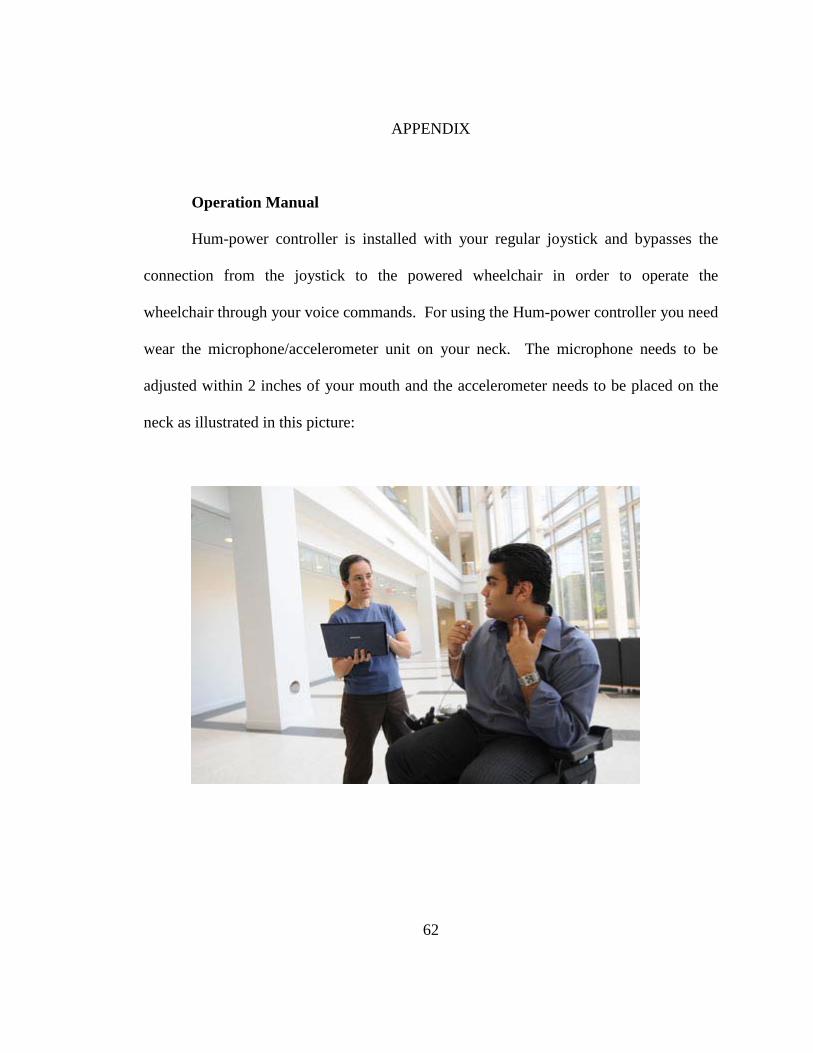
62
APPENDIX
Operation Manual
Hum-power controller is installed with your regular joystick and bypasses the
connection from the joystick to the powered wheelchair in order to operate the
wheelchair through your voice commands. For using the Hum-power controller you need
wear the microphone/accelerometer unit on your neck. The microphone needs to be
adjusted within 2 inches of your mouth and the accelerometer needs to be placed on the
neck as illustrated in this picture:
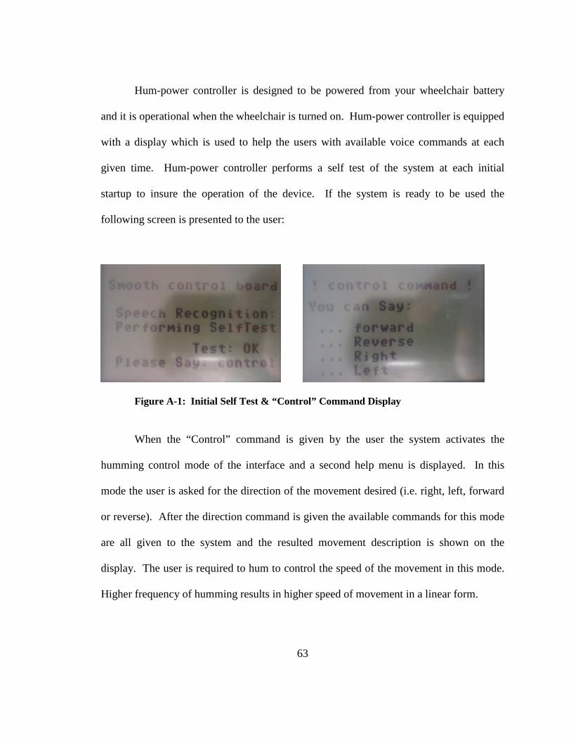
63
Hum-power controller is designed to be powered from your wheelchair battery
and it is operational when the wheelchair is turned on. Hum-power controller is equipped
with a display which is used to help the users with available voice commands at each
given time. Hum-power controller performs a self test of the system at each initial
startup to insure the operation of the device. If the system is ready to be used the
following screen is presented to the user:
Figure A-1: Initial Self Test & “Control” Command Display
When the “Control” command is given by the user the system activates the
humming control mode of the interface and a second help menu is displayed. In this
mode the user is asked for the direction of the movement desired (i.e. right, left, forward
or reverse). After the direction command is given the available commands for this mode
are all given to the system and the resulted movement description is shown on the
display. The user is required to hum to control the speed of the movement in this mode.
Higher frequency of humming results in higher speed of movement in a linear form.
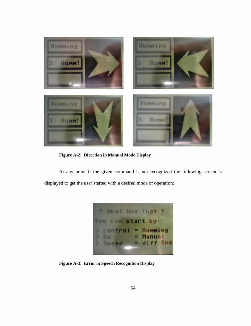
64
Figure A-2: Direction in Manual Mode Display
At any point if the given command is not recognized the following screen is
displayed to get the user started with a desired mode of operation:
Figure A-3: Error in Speech Recognition Display

65
Users can perform maneuvers in the manual mode by giving the “Go” command.
This mode is similar to the humming mode, but after the direction command is given
speed is set to be at level of 25%.
Figure A-4: “Go” Command and Direction in Automatic Mode Display
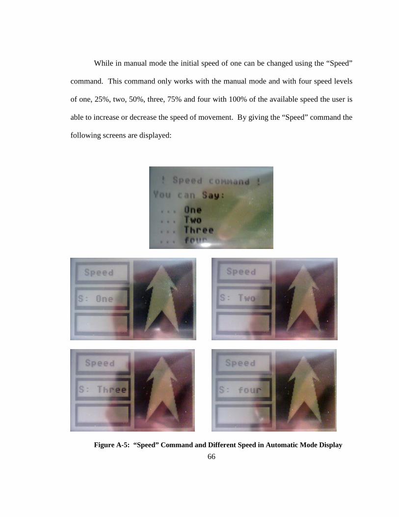
66
While in manual mode the initial speed of one can be changed using the “Speed”
command. This command only works with the manual mode and with four speed levels
of one, 25%, two, 50%, three, 75% and four with 100% of the available speed the user is
able to increase or decrease the speed of movement. By giving the “Speed” command the
following screens are displayed:
Figure A-5: “Speed” Command and Different Speed in Automatic Mode Display

67
REFERENCES
68
REFERENCES [1] S. Aoshima, H. Kaminaga and M. Shiraishi, "One-hand drive-type power-assisted
wheelchair with a direction control device using pneumatic pressure," Adv. Rob., vol. 16, pp. 773-84, 2002.
[2] K. Arshak, D. Buckley. Review of Assistive Devices for Electric Powered Wheelchairs Navigation. ITB Journal, vol. 13, pp. 13-23, 2006
[3] D. Bayer, J. Springsteen and R. Nash, "A next generation intelligent wheelchair control system," in Technology and Persons with Disabilities, 1992, pp. 41-5.
[4] M. Brookes, "VOICEBOX, the Speech Processing Toolbox for MATLAB," v 1.5, London, 2006.
[5] Chung-Hsien Kuo and H. H. W. Chen, "Human-Oriented Design of Autonomous Navigation Assisted Robotic Wheelchair for Indoor Environments," Mechatronics, 2006 IEEE International Conference on, pp. 230-235, 2006.
[6] Chung-Hsien Kuo, Hung-Wen Yeh and Chin-En Wu, "Development of autonomous navigation robotic wheelchairs using programmable System-on-Chip based distributed computing architecture," Systems, Man and Cybernetics, 2007. ISIC. IEEE International Conference on, pp. 2939-2944, 2007.
[7] Chung-Hsien Kuo, Hung-Wen Yeh, Chin-En Wu and Ko-Ming Hsiao, "Development of Autonomous Robotic Wheelchair Controller Using Embedded Systems," Industrial Electronics Society, 2007. IECON 2007. 33rd Annual Conference of the IEEE, pp. 3001-3006, 2007.
[8] Chung-Hsien Kuo, Jia-Wun Siao and Kuo-Wei Chiu, "Development of an intelligent power assisted wheelchair using fuzzy control systems," Systems, Man and Cybernetics, 2008. SMC 2008. IEEE International Conference on, pp. 2578-2583, 2008.
[9] R. A. Cooper, "Intelligent control of power wheelchairs," Engineering in Medicine and Biology Magazine, IEEE, vol. 14, pp. 423-431, 1995.
[10] R. A. Cooper, M. L. Boninger, D. M. Spaeth, D. Ding, Songfeng Guo, A. M. Koontz, S. G. Fitzgerald, R. Cooper, A. Kelleher and D. M. Collins, "Engineering
69
Better Wheelchairs to Enhance Community Participation," Neural Systems and Rehabilitation Engineering, IEEE Transactions on, vol. 14, pp. 438-455, 2006.
[11] D. Ding and R. A. Cooper, "Electric powered wheelchairs," Control Systems Magazine, IEEE, vol. 25, pp. 22-34, 2005.
[12] N. R. Dixon and T. B. Martin, Automatic Speech & Speaker Recognition. New York: IEEE Press : distributor, Wiley, 1979, pp. 433.
[13] P. M. Faria, R. A. M. Braga, E. Valgode and L. P. Reis, "Interface Framework to Drive an Intelligent Wheelchair Using Facial Expressions," Industrial Electronics, 2007. ISIE 2007. IEEE International Symposium on, pp. 1791-1796, 2007.
[14] A. Fattouh and S. Nader, "Preliminary Results on Dynamic Obstacle Avoidance for Powered Wheelchair," Information and Communication Technologies, 2006. ICTTA '06. 2nd, vol. 1, pp. 849-853, 2006.
[15] L. Fehr, W. E. Langbein and S. B. Skaar, Adequacy of power wheelchair control interfaces for persons with severe disabilities: A clinical survey, Journal of Rehabilitation Research and Development. vol. 37 no. 3, 2000, pp. 353-360.
[16] T. Felzer and B. Freisleben, "HaWCoS: The "hands-free" wheelchair control system," in ASSETS 2002: Proceedings of the 5th International ACM SIGCAPH Conference on Assistive Technologies, July 08,2002 - July 10, 2002, pp. 127-134.
[17] M. Fezari and A. -. Khati, "New speech processor and ultrasonic sensors based embedded system to improve the control of a motorised wheelchair," Design and Test Workshop, 2008. IDT 2008. 3rd International, pp. 345-349, 2008.
[18] J. Hansen, NexTTool. NexTTool is developed by John Hansen and is freely distributed as part of the BrixCC NXT development suite, 2006.
[19] C. S. Harrison, M. Grant and B. A. Conway, "Haptic interfaces for wheelchair navigation in the built environment," Presence, vol. 13, pp. 520-34, 10. 2004.
[20] C. Huddleston, Intelligent Sensor Design using the Microchip dsPIC. Amsterdam ; Boston: Elsevier/Newnes, 2007, pp. 283.
[21] T. Joseph and Hung Nguyen, "Neural network control of wheelchairs using telemetric head movement," Engineering in Medicine and Biology Society, 1998. Proceedings of the 20th Annual International Conference of the IEEE, vol. 5, pp. 2731-2733 vol.5, 1998.
70
[22] K. Kuah, M. Bodruzzaman and S. Zein-Sabatto, "A neural network-based text independent voice recognition system," Southeastcon '94. 'Creative Technology Transfer - A Global Affair'. , Proceedings of the 1994 IEEE, pp. 131-135, 1994.
[23] Y. Kuno, N. Shimada and Y. Shirai, "Look where you're going [robotic wheelchair]," Robotics & Automation Magazine, IEEE, vol. 10, pp. 26-34, 2003.
[24] W. N. Lam, A. F. T. Mak, W. C. Tam and R. A. Cooper, "Kinematics of the wrist, elbow and shoulder during manual wheelchair maneuvers," [Engineering in Medicine and Biology, 2002. 24th Annual Conference and the Annual Fall Meeting of the Biomedical Engineering Society] EMBS/BMES Conference, 2002. Proceedings of the Second Joint, vol. 3, pp. 2573-2576 vol.3, 2002.
[25] S. P. Levine, D. A. Bell, L. A. Jaros, R. C. Simpson, Y. Koren and J. Borenstein, "The NavChair Assistive Wheelchair Navigation System," Rehabilitation Engineering, IEEE Transactions on, vol. 7, pp. 443-451, 1999.
[26] Liu Chong and Wang Hong, "The Design of Wheelchair Based on SEMG Control," Bioinformatics and Biomedical Engineering, 2008. ICBBE 2008. the 2nd International Conference on, pp. 1721-1724, 2008.
[27] Y. Matsumotot, T. Ino and T. Ogsawara, "Development of intelligent wheelchair system with face and gaze based interface," Robot and Human Interactive Communication, 2001. Proceedings. 10th IEEE International Workshop on, pp. 262-267, 2001.
[28] L. Mclaughlin, "Silencing voice recognition technology," Intelligent Systems, IEEE, vol. 19, pp. 4-6, 2004.
[29] S. Molau, M. Pitz, R. Schluter and H. Ney, "Computing Mel-frequency cepstral coefficients on the power spectrum," Acoustics, Speech, and Signal Processing, 2001. Proceedings. (ICASSP '01). 2001 IEEE International Conference on, vol. 1, pp. 73-76 vol.1, 2001.
[30] National Spinal Cord Injury Statistical Center, NSCISC Annual Statistical Report - Complete Public Version. 2007. Birmingham, Alabama.
[31] H. G. Nik, G. M. Gutt and N. Peixoto, "Voice Recognition Algorithm for Portable Assistive Devices," Sensors, 2007 IEEE, pp. 997-1000, 2007.
[32] S. Oh and Y. Hori, "Development of a novel instantaneous speed observer and its application to the power-assisted wheelchair control," Power Electronics and Motion Control Conference, 2004. IPEMC 2004. the 4th International, vol. 3, pp. 1471-1476 Vol.3, 2004.
71
[33] H. Osada, "Evaluation method for a voice recognition system modeled with discrete Markov chain," Communications, Computers and Signal Processing, 1997. '10 Years PACRIM 1987-1997 - Networking the Pacific Rim'. 1997 IEEE Pacific Rim Conference on, vol. 2, pp. 600-602 vol.2, 1997.
[34] G. Pacnik, K. Benkic and B. Brecko, "Voice operated intelligent wheelchair - VOIC," Industrial Electronics, 2005. ISIE 2005. Proceedings of the IEEE International Symposium on, vol. 3, pp. 1221-1226 vol. 3, 2005.
[35] A. Papandreou-Suppappola, Applications in Time-Frequency Signal Processing. Boca Raton: CRC Press, 2003, pp. 409.
[36] S. P. Parikh, V. Grassi Jr., V. Kumar and J. Okamoto Jr., "Integrating Human Inputs with Autonomous Behaviors on an Intelligent Wheelchair Platform," Intelligent Systems, IEEE, vol. 22, pp. 33-41, 2007.
[37] A. M. Peinado, J. C. Segura, A. J. Rubio, P. Garcia and J. L. Perez, "Discriminative codebook design using multiple vector quantization," Speech and Audio Processing, IEEE Transactions on, vol. 4, pp. 89-95, 1996.
[38] H. Perez-Meana, Advances in Audio and Speech Signal Processing : Technologies and Applications. Hershey, PA: Idea Group Pub., 2007, pp. 446.
[39] Qiang Zeng, B. Rebsamen, E. Burdet and Chee Leong Teo, "A Collaborative Wheelchair System," Neural Systems and Rehabilitation Engineering, IEEE Transactions on, vol. 16, pp. 161-170, 2008.
[40] L. R. Rabiner, "A tutorial on hidden Markov models and selected applications in speech recognition," Proceedings of the IEEE, vol. 77, pp. 257-286, 1989.
[41] Ruei-Xi Chen, Liang-Gee Chen and Lilin Chen, "System design consideration for digital wheelchair controller," Industrial Electronics, IEEE Transactions on, vol. 47, pp. 898-907, 2000.
[42] M. Sajkowski, "Voice control of dual-drive mobile robots-survey of algorithms," Robot Motion and Control, 2002. RoMoCo '02. Proceedings of the Third International Workshop on, pp. 387-392, 2002.
[43] J. Sanchez and M. P. Canton, Microcontroller Programming : The Microchip PIC. Boca Raton, FL: CRC Press, 2007, pp. 804.
[44] Seung-Hyun Lim and Jae Wook Jeon, "Multiple mobile robot interface using a low cost voice recognition chip," Robot and Human Communication, 1997. RO-MAN '97. Proceedings. , 6th IEEE International Workshop on, pp. 402-407, 1997.
72
[45] R. C. Simpson and S. P. Levine, "Voice control of a powered wheelchair," Neural Systems and Rehabilitation Engineering, IEEE Transactions on, vol. 10, pp. 122-125, 2002.
[46] R. C. Simpson and S. P. Levine, "Automatic adaptation in the NavChair Assistive Wheelchair Navigation System," Rehabilitation Engineering, IEEE Transactions on, vol. 7, pp. 452-463, 1999.
[47] R. C. Simpson and S. P. Levine, "Adaptive shared control of a smart wheelchair operated by voice control," Intelligent Robots and Systems, 1997. IROS '97. , Proceedings of the 1997 IEEE/RSJ International Conference on, vol. 2, pp. 622-626 vol.2, 1997.
[48] R. C. Simpson, D. Poirot and F. Baxter, "The Hephaestus Smart Wheelchair system," Neural Systems and Rehabilitation Engineering, IEEE Transactions on, vol. 10, pp. 118-122, 2002.
[49] S. W. Smith, The Scientist and Engineer's Guide to Digital Signal Processing. ,1st ed.San Diego, Calif.: California Technical Pub., 1997, pp. 626.
[50] Y. Takahashi, M. Kohda, Y. Shinoda and K. Kubota, "Psychological flutter of robotic wheelchair with inverse pendulum control," Industrial Electronics, 2008. ISIE 2008. IEEE International Symposium on, pp. 1318-1323, 2008.
[51] Z. Tan and B. Lindberg, Automatic Speech Recognition on Mobile Devices and Over Communication Networks. London: Springer, 2008, pp. 401.
[52] J. Yuan, "Stability analyses of wheelchair robot based on “Human-in-the-Loop” control theory," Robotics and Biomimetics, 2008. ROBIO 2009. IEEE International Conference on, pp. 419-424, 2009.
73
CURRICULUM VITAE
Hossein Ghaffari Nik was born in Tehran, Iran. He moved to the United States in 2001 and graduated from Oakton High School, Fairfax, Virginia, in 2003. Hossein received his Associate of Science in Electrical Engineering from Northern Virginia Community College in 2005. He joined George Mason University in Spring of 2005 and received his Bachelor of Science in Electrical Engineering in 2007. While pursuing his Master of Science he worked as a graduate teaching and research assistant at George Mason University’s Electrical and Computer Engineering department.