DNV Ship rules Pt.3 Ch.2 - Hull Structural Design, Ships with Length ...
Upload
trinhquynhCategory
view
236download
0
Hull Structure and Arrangement
for the Classifi cation of
Cargo Ships less than 65 m and
Non Cargo Ships less than 90 m
Rule Note December 2017
NR 600 DT R02 E

Hull Structure and Arrangement for the Classification of
Cargo Ships less than 65 m and Non Cargo Ships less than 90 m
December 2017
Rule Note NR 600 DT R02 E
Marine & Offshore 92937 Paris la Défense Cedex – France
Tel: + 33 (0)1 55 24 70 00 – Fax: + 33 (0)1 55 24 70 25 Website: http://www.veristar.com
Email: [email protected] 2017 Bureau Veritas - All rights reserved
1. INDEPENDENCY OF THE SOCIETY AND APPLICABLE TERMS1.1. The Society shall remain at all times an independent contractorand neither the Society nor any of its officers, employees, servants,agents or subcontractors shall be or act as an employee, servant oragent of any other party hereto in the performance of the Services.1.2. The operations of the Society in providing its Services are exclu-sively conducted by way of random inspections and do not, in any cir-cumstances, involve monitoring or exhaustive verification.1.3. The Society acts as a services provider. This cannot be construedas an obligation bearing on the Society to obtain a result or as a war-ranty. The Society is not and may not be considered as an underwriter,broker in Unit's sale or chartering, expert in Unit's valuation, consultingengineer, controller, naval architect, manufacturer, shipbuilder, repairor conversion yard, charterer or shipowner; none of them above listedbeing relieved of any of their expressed or implied obligations as a re-sult of the interventions of the Society.1.4. The Services are carried out by the Society according to the appli-cable Rules and to the Bureau Veritas' Code of Ethics. The Societyonly is qualified to apply and interpret its Rules.1.5. The Client acknowledges the latest versions of the Conditions andof the applicable Rules applying to the Services' performance.1.6. Unless an express written agreement is made between the Partieson the applicable Rules, the applicable Rules shall be the rules applica-ble at the time of the Services' performance and con tract's execution.1.7. The Services' performance is solely based on the Conditions. Noother terms shall apply whether express or implied.
2. DEFINITIONS2.1. "Certificate(s)" means class certificates, attestations and reportsfollowing the Society's intervention. The Certificates are an appraise-ment given by the Society to the Client, at a certain date, following sur-veys by its surveyors on the level of compliance of the Unit to theSociety's Rules or to the documents of reference for the Services pro-vided. They cannot be construed as an implied or express warranty ofsafety, fitness for the purpose, seaworthiness of the Unit or of its valuefor sale, insurance or chartering.2.2. "Certification" means the activity of certification in application ofnational and international regulations or standards, in particular by del-egation from different governments that can result in the issuance of acertificate.2.3. "Classification" means the classification of a Unit that can resultor not in the issuance of a class certificate with reference to the Rules.2.4. "Client" means the Party and/or its representative requesting theServices.2.5. "Conditions" means the terms and conditions set out in thepresent document.2.6. "Industry Practice" means International Maritime and/or Offshoreindustry practices.2.7. "Intellectual Property" means all patents, rights to inventions, utilitymodels, copyright and related rights, trade marks, logos, service marks,trade dress, business and domain names, rights in trade dress or get-up,rights in goodwill or to sue for passing off, unfair competition rights, rightsin designs, rights in computer software, database rights, topographyrights, moral rights, rights in confidential information (including know-how and trade secrets), methods and proto cols for Services, and anyother intellectual property rights, in each case whether capable of regis-tration, registered or unregistered and including all applications for andrenewals, reversions or extensions of such rights, and all similar orequivalent rights or forms of protection in any part of the world.2.8. "Parties" means the Society and Client together.2.9. "Party" means the Society or the Client.2.10. "Register" means the register published annually by the Society.2.11. "Rules" means the Society's classification rules, guidance notes andother documents. The Rules, procedures and instructions of the Societytake into account at the date of their preparation the state of currently avail-able and proven technical minimum requirements but are not a standardor a code of construction neither a guide for maintenance, a safety hand-book or a guide of professional practices, all of which are assumed to beknown in detail and carefully followed at all times by the Client.2.12. "Services" means the services set out in clauses 2.2 and 2.3 butalso other services related to Classification and Certification such as, butnot limited to: ship and company safety management certification, shipand port security certification, training activities, all activities and dutiesincidental thereto such as documentation on any supporting means, soft-ware, instrumentation, measurements, tests and trials on board.2.13. "Society" means the classification society 'Bureau Veritas Ma-rine & Offshore SAS', a company organized and existing under thelaws of France, registered in Nanterre under the number 821 131 844,or any other legal entity of Bureau Veritas Group as may be specifiedin the relevant contract, and whose main activities are Classificationand Certification of ships or offshore units.2.14. "Unit" means any ship or vessel or offshore unit or structure ofany type or part of it or system whether linked to shore, river bed or seabed or not, whether operated or located at sea or in inland waters orpartly on land, including submarines, hovercrafts, drilling rigs, offshoreinstallations of any type and of any purpose, their related and ancillaryequipment, subsea or not, such as well head and pipelines, mooringlegs and mooring points or otherwise as decided by the Society.
3. SCOPE AND PERFORMANCE3.1. The Society shall perform the Services according to the applicablenational and international standards and Industry Practice and alwayson the assumption that the Client is aware of such standards and In-dustry Practice.
3.2. Subject to the Services performance and always by reference tothe Rules, the Society shall:• review the construction arrangements of the Unit as shown on the
documents provided by the Client;• conduct the Unit surveys at the place of the Unit construction;• class the Unit and enters the Unit's class in the Society's Register;• survey the Unit periodically in service to note that the requirements
for the maintenance of class are met. The Client shall inform theSociety without delay of any circumstances which may cause anychanges on the conducted surveys or Services.
The Society will not:• declare the acceptance or commissioning of a Unit, nor its construc-
tion in conformity with its design, such activities remaining under the exclusive responsibility of the Unit's owner or builder;
• engage in any work relating to the design, construction, production or repair checks, neither in the operation of the Unit or the Unit's trade, neither in any advisory services, and cannot be held liable on those accounts.
4. RESERVATION CLAUSE4.1. The Client shall always: (i) maintain the Unit in good condition aftersurveys; (ii) present the Unit after surveys; (iii) present the Unit for sur-veys; and (iv) inform the Society in due course of any circumstancesthat may affect the given appraisement of the Unit or cause to modifythe scope of the Services.4.2. Certificates referring to the Society's Rules are only valid if issuedby the Society.4.3. The Society has entire control over the Certificates issued andmay at any time withdraw a Certificate at its entire discretion including,but not limited to, in the following situations: where the Client fails tocomply in due time with instructions of the Society or where the Clientfails to pay in accordance with clause 6.2 hereunder.
5. ACCESS AND SAFETY5.1. The Client shall give to the Society all access and information nec-essary for the efficient performance of the requested Services. The Cli-ent shall be the sole responsible for the conditions of presentation ofthe Unit for tests, trials and surveys and the conditions under whichtests and trials are carried out. Any information, drawings, etc. requiredfor the performance of the Services must be made available in duetime.5.2. The Client shall notify the Society of any relevant safety issue andshall take all necessary safety-related measures to ensure a safe workenvironment for the Society or any of its officers, employees, servants,agents or subcontractors and shall comply with all applicable safetyregulations.6. PAYMENT OF INVOICES6.1. The provision of the Services by the Society, whether complete ornot, involve, for the part carried out, the payment of fees thirty (30) daysupon issuance of the invoice.6.2. Without prejudice to any other rights hereunder, in case of Client'spayment default, the Society shall be entitled to charge, in addition tothe amount not properly paid, interests equal to twelve (12) months LI-BOR plus two (2) per cent as of due date calculated on the number ofdays such payment is delinquent. The Society shall also have the rightto withhold certificates and other documents and/or to suspend or re-voke the validity of certificates.6.3. In case of dispute on the invoice amount, the undisputed portionof the invoice shall be paid and an explanation on the dispute shall ac-company payment so that action can be taken to solve the dispute.7. 7. LIABILITY7.1. The Society bears no liability for consequential loss. For the pur-pose of this clause consequential loss shall include, without limitation:• Indirect or consequential loss;• Any loss and/or deferral of production, loss of product, loss of use,
loss of bargain, loss of revenue, loss of profit or anticipated profit,loss of business and business interruption, in each case whetherdirect or indirect.
The Client shall save, indemnify, defend and hold harmless the Societyfrom the Client's own consequential loss regardless of cause.7.2. In any case, the Society's maximum liability towards the Client islimited to one hundred and fifty per-cents (150%) of the price paid bythe Client to the Society for the performance of the Services. This limitapplies regardless of fault by the Society, including breach of contract,breach of warranty, tort, strict liability, breach of statute. 7.3. All claims shall be presented to the Society in writing within three(3) months of the Services' performance or (if later) the date when theevents which are relied on were first discovered by the Client. Anyclaim not so presented as defined above shall be deemed waived andabsolutely time barred.
8. INDEMNITY CLAUSE8.1. The Client agrees to release, indemnify and hold harmless the So-ciety from and against any and all claims, demands, lawsuits or actionsfor damages, including legal fees, for harm or loss to persons and/orproperty tangible, intangible or otherwise which may be broughtagainst the Society, incidental to, arising out of or in connection withthe performance of the Services except for those claims caused solelyand completely by the negligence of the Society, its officers, employ-ees, servants, agents or subcontractors.
9. TERMINATION9.1. The Parties shall have the right to terminate the Services (and therelevant contract) for convenience after giving the other Party thirty(30) days' written notice, and without prejudice to clause 6 above.
9.2. In such a case, the class granted to the concerned Unit and thepreviously issued certificates shall remain valid until the date of effectof the termination notice issued, subject to compliance with clause 4.1and 6 above.10. FORCE MAJEURE10.1. Neither Party shall be responsible for any failure to fulfil any termor provision of the Conditions if and to the extent that fulfilment hasbeen delayed or temporarily prevented by a force majeure occurrencewithout the fault or negligence of the Party affected and which, by theexercise of reasonable diligence, the said Party is unable to provideagainst.10.2. For the purpose of this clause, force majeure shall mean any cir-cumstance not being within a Party's reasonable control including, butnot limited to: acts of God, natural disasters, epidemics or pandemics,wars, terrorist attacks, riots, sabotages, impositions of sanctions, em-bargoes, nuclear, chemical or biological contaminations, laws or actiontaken by a government or public authority, quotas or prohibition, expro-priations, destructions of the worksite, explosions, fires, accidents, anylabour or trade disputes, strikes or lockouts
11. CONFIDENTIALITY11.1. The documents and data provided to or prepared by the Societyin performing the Services, and the information made available to theSociety, are treated as confidential except where the information:• is already known by the receiving Party from another source and is
properly and lawfully in the possession of the receiving Party priorto the date that it is disclosed;
• is already in possession of the public or has entered the publicdomain, otherwise than through a breach of this obligation;
• is acquired independently from a third party that has the right to dis-seminate such information;
• is required to be disclosed under applicable law or by a governmen-tal order, decree, regulation or rule or by a stock exchange authority(provided that the receiving Party shall make all reasonable effortsto give prompt written notice to the disclosing Party prior to suchdisclosure.
11.2. The Society and the Client shall use the confidential informationexclusively within the framework of their activity underlying these Con-ditions.11.3. Confidential information shall only be provided to third partieswith the prior written consent of the other Party. However, such priorconsent shall not be required when the Society provides the confiden-tial information to a subsidiary.11.4. The Society shall have the right to disclose the confidential infor-mation if required to do so under regulations of the International Asso-ciation of Classifications Societies (IACS) or any statutory obligations.
12. INTELLECTUAL PROPERTY12.1. Each Party exclusively owns all rights to its Intellectual Propertycreated before or after the commencement date of the Conditions andwhether or not associated with any contract between the Parties.12.2. The Intellectual Property developed for the performance of theServices including, but not limited to drawings, calculations, and re-ports shall remain exclusive property of the Society.13. ASSIGNMENT13.1. The contract resulting from to these Conditions cannot be as-signed or transferred by any means by a Party to a third party withoutthe prior written consent of the other Party.13.2. The Society shall however have the right to assign or transfer byany means the said contract to a subsidiary of the Bureau VeritasGroup.
14. SEVERABILITY14.1. Invalidity of one or more provisions does not affect the remainingprovisions.14.2. Definitions herein take precedence over other definitions whichmay appear in other documents issued by the Society.14.3. In case of doubt as to the interpretation of the Conditions, theEnglish text shall prevail.
15. GOVERNING LAW AND DISPUTE RESOLUTION15.1. The Conditions shall be construed and governed by the laws ofEngland and Wales.15.2. The Society and the Client shall make every effort to settle anydispute amicably and in good faith by way of negotiation within thirty(30) days from the date of receipt by either one of the Parties of a writ-ten notice of such a dispute.15.3. Failing that, the dispute shall finally be settled by arbitration underthe LCIA rules, which rules are deemed to be incorporated by refer-ence into this clause. The number of arbitrators shall be three (3). Theplace of arbitration shall be London (UK).
16. PROFESSIONNAL ETHICS16.1. Each Party shall conduct all activities in compliance with all laws,statutes, rules, and regulations applicable to such Party including butnot limited to: child labour, forced labour, collective bargaining, discrim-ination, abuse, working hours and minimum wages, anti-bribery, anti-corruption. Each of the Parties warrants that neither it, nor its affiliates,has made or will make, with respect to the matters provided for here-under, any offer, payment, gift or authorization of the payment of anymoney directly or indirectly, to or for the use or benefit of any official oremployee of the government, political party, official, or candidate.16.2. In addition, the Client shall act consistently with the Society'sCode of Ethics of Bureau Veritas. http://www.bureauveritas.com/home/about-us/ethics+and+compliance/
Bureau Veritas Marine & Offshore General Conditions - Edition January 2017
MARINE & OFFSHORE - GENERAL CONDITIONS
RULE NOTE NR 600
NR 600Hull Structure and Arrangement
for the Classification ofCargo Ships less than 65 m andNon Cargo Ships less than 90 m
Chapters 1 2 3 4 5 6
Chapter 1 General
Chapter 2 Structure Design Principles, General Arrangement and Scantling Cri-teria
Chapter 3 Design Loads
Chapter 4 Hull Scantling
Chapter 5 Other Structures
Chapter 6 Additional Requirements in Relation to the Service Notation or Ser-vice Feature Assigned to the Ship
Chapter 7 Construction and Testing
December 2017

Unless otherwise specified, these rules apply to ships for which contracts aresigned after December 1st, 2017. The Society may refer to the contents hereofbefore December 1st, 2017, as and when deemed necessary or appropriate.
2 Bureau Veritas December 2017
CHAPTER 1GENERAL
Section 1 General
1 Application criteria 25
1.1 Types of ships covered by the present Rules1.2 Types of ships not covered by the present Rules1.3 Particular cases
2 General 25
2.1 Wording2.2 Classification
3 Navigation coefficient 26
3.1 Ships with a navigation notation3.2 Sea going launch and launch
4 Definitions 27
4.1 Moulded base line4.2 Lengths4.3 Breadth4.4 Depth D4.5 Moulded draught T4.6 Total block coefficient CB4.7 Chine and bottom4.8 Lightweight4.9 Deadweight4.10 Freeboard deck4.11 Bulkhead deck4.12 Superstructure4.13 Multihull platform
5 Reference co-ordinate system 28
5.1 General
6 Stability 29
6.1 General
7 Documentation to be submitted 29
7.1 Documentation to be submitted
Section 2 Materials
1 General 31
1.1 Application
2 Steels for hull structure 31
2.1 General
3 Aluminium alloys for hull structure 32
3.1 Characteristics and testing
December 2017 Bureau Veritas 3

4 Composite materials and plywood for hull structure 32
4.1 Characteristics and testing4.2 Application
Section 3 Scantling Principles
1 Main scantling principles 33
1.1 General1.2 Type of ships1.3 Corrosion addition1.4 Rounding off
2 Hull analysis approach 34
2.1 Global hull girder strength and local strength
4 Bureau Veritas December 2017

CHAPTER 2STRUCTURE DESIGN PRINCIPLES, GENERAL ARRANGEMENT AND SCANTLING CRITERIA
Section 1 Structure Design Principles
1 General 37
1.1 Application
2 Structural continuity of hull girder 37
2.1 General principles for longitudinal hull girder2.2 General principles for multihull platform2.3 Insert plates and doublers2.4 Connection between steel and aluminium
3 Bottom structure arrangement 38
3.1 General arrangement3.2 Longitudinal framing arrangement of single bottom3.3 Transverse framing arrangement of single bottom3.4 Double bottom arrangement3.5 Arrangement, scantlings and connections of bilge keels
4 Side structure arrangement 39
4.1 General4.2 Stiffener arrangement4.3 Openings in the side shell plating
5 Deck structure arrangement 40
5.1 General5.2 Opening arrangement5.3 Hatch supporting structures5.4 Pillar arrangement under deck5.5 Deck structure in way of launching appliances used for survival craft or rescue
boats
6 Bulkhead structure arrangement 41
6.1 General6.2 Watertight bulkheads6.3 Non-tight bulkheads6.4 Corrugated bulkheads6.5 Bulkheads acting as pillars6.6 Bracketed stiffeners
7 Superstructures and deckhouses 42
7.1 Connection of superstructures and deckhouses with the hull structure7.2 Structural arrangement of superstructures and deckhouses
December 2017 Bureau Veritas 5
Section 2 Subdivision, Compartment Arrangement and Arrangement of Hull Openings
1 General 43
1.1 Application
2 Definition 43
2.1 Load line length LLL2.2 Machinery spaces of category A
3 Subdivision arrangement 43
3.1 Number of transverse watertight bulkheads3.2 Water ingress detection3.3 Collision bulkhead3.4 After peak bulkheads, machinery space bulkheads and sterntubes3.5 Height of transverse watertight bulkheads other than collision bulkhead and
after peak bulkheads3.6 Openings in watertight bulkheads and decks - Ships with service notation other
than passenger ship or ro-ro passenger ship
4 Compartment arrangement 46
4.1 Definitions4.2 Cofferdam arrangement4.3 Double bottom4.4 Compartments forward of the collision bulkhead4.5 Minimum bow height4.6 Shaft tunnels4.7 Watertight ventilators and trunks4.8 Fuel oil tanks
5 Access arrangement 47
5.1 General5.2 Double bottom5.3 Access arrangement to, and within, spaces in, and forward of, the cargo area5.4 Shaft tunnels5.5 Access to steering gear compartment
Section 3 Scantling Criteria
1 General 50
1.1 Application1.2 Global and local stresses1.3 Stress notation
2 Steel and aluminium alloy structures 50
2.1 Permissible stresses under global loads2.2 Permissible stresses under local loads2.3 Permissible stresses of primary stiffeners under global and local loads
3 Composite material structure 53
3.1 General3.2 Rule safety factors
4 Plywood structure 55
4.1 General4.2 Rule safety factors
6 Bureau Veritas December 2017
CHAPTER 3DESIGN LOADS
Section 1 General
1 Application 59
1.1 General
2 Definition 59
2.1 Hull girder loads2.2 Local external pressures2.3 Local internal pressures and forces
3 Local pressure application 59
3.1 Application
4 Local load point location 60
4.1 General case for structures made of steel or aluminium alloys4.2 General case for structures made of composite materials4.3 Superstructures and deckhouses
Section 2 Hull Girder Loads
1 General 61
1.1 Hull girder loads
2 Calculation convention 61
2.1 Sign conventions of global bending moments and shear forces2.2 Designation of global bending moments and shear forces
3 Combination of hull girder loads 62
3.1 Hull girder load combinations3.2 Hull girder loads distribution
4 Still water loads 62
4.1 Cargo ships4.2 Non cargo ships
5 Wave loads 63
5.1 General5.2 Wave loads in head sea condition5.3 Wave loads in quartering sea condition for multihull
6 Additional specific wave hull girder loads 66
6.1 Additional wave loads for planing hull6.2 Additional wave loads for multihull
December 2017 Bureau Veritas 7
Section 3 Local External Pressures
1 Definitions 69
1.1 General
2 Sea pressures 70
2.1 Ship relative motions2.2 Sea pressures
3 Dynamic sea pressures 71
3.1 Side shell impact and platform bottom impact3.2 Bottom impact pressure for flat bottom forward area3.3 Bottom slamming for planing hull
Section 4 Local Internal Pressures and Forces
1 Application 76
1.1 General
2 Ship accelerations 76
2.1 Reference values2.2 Vertical accelerations
3 Internal loads 77
3.1 Liquids3.2 Dry cargoes3.3 Wheeled loads
4 Loads on deck 79
4.1 Exposed deck4.2 Accommodation deck4.3 Specific loads on deck
5 Testing loads 81
5.1 General
6 Flooding loads 81
6.1 General
8 Bureau Veritas December 2017
CHAPTER 4HULL SCANTLING
Section 1 General
1 Materials 85
1.1 General
2 Structure scantling approach 85
2.1 General2.2 Global strength analysis2.3 Local scantling analysis2.4 Specific cases
Section 2 Global Strength Analysis
1 General 86
1.1 Application1.2 Global strength calculation
2 Global strength check 86
2.1 General2.2 Maximum stress check2.3 Buckling check
3 Calculation of global strength for monohull ship 87
3.1 General3.2 Strength characteristics3.3 Overall stresses
4 Calculation of global strength for multihull 88
4.1 General4.2 Global strength in head sea condition4.3 Global strength in quartering sea and in digging in waves4.4 Transverse bending moment acting on twin-hull connections of swath4.5 Global strength for planing hull
Section 3 Local Plating Scantling
1 General 92
1.1 General1.2 Local loads
2 Plating scantling 92
2.1 General2.2 Scantling for steel and aluminium plating2.3 Scantling for composite panel
December 2017 Bureau Veritas 9
Section 4 Local Secondary Stiffener Scantling
1 General 96
1.1 Local scantling1.2 Local loads1.3 Section modulus calculation1.4 End stiffener conditions for section moduli calculation1.5 Span of stiffener
2 Secondary stiffener scantling 98
2.1 General2.2 Scantling for steel and aluminium secondary stiffener2.3 Scantling of secondary stiffeners in composite materials
Section 5 Local Primary Stiffener Scantling
1 General 101
1.1 Local scantling1.2 Structural beam models1.3 Finite element model1.4 Beam section modulus calculation1.5 End stiffener conditions for calculation
2 Primary stiffener scantling analysed by isolated beam calculation under local loads 102
2.1 Scantling for steel and aluminium primary stiffeners under lateral loads2.2 Scantling for steel and aluminium primary stiffeners under wheeled loads2.3 Primary stiffeners in composite materials2.4 Scantling of primary stiffeners in way of launching appliances used for survival
craft or rescue boat
3 Specific requirements 104
3.1 General3.2 Cut-outs and large openings 3.3 Web stiffening arrangement for primary supporting members
Section 6 Stiffener Brackets Scantling and Stiffener End Connections
1 General arrangement of brackets 107
1.1 Materials1.2 General requirements
2 Bracket for connection of perpendicular stiffeners 108
2.1 General arrangement
3 Bracket ensuring continuity of secondary stiffeners 108
3.1 General
4 Bracketless end stiffeners connections 109
4.1 Bracketless end connections4.2 Other type of end connection
10 Bureau Veritas December 2017
Section 7 Pillar Scantling
1 General 110
1.1 Materials1.2 Application
2 Pillar in steel material 111
2.1 Buckling of pillars subjected to compression axial load2.2 Buckling of pillars subjected to compression axial load and bending moments2.3 Pillars in tanks2.4 Vertical bulkhead stiffener acting as pillar
3 Pillar in aluminium material 112
3.1 General
4 Pillar in composite material 112
4.1 Scantling criteria
Appendix 1 Calculation of the Critical Buckling Stresses
1 General 113
1.1 Application
2 Plating 113
2.1 Calculation hypothesis
3 Stiffeners 115
3.1 Calculation hypothesis
Appendix 2 Hull Scantling Check with Local and Global Stresses Combination Criteria
1 General 117
1.1 Application1.2 Overall stresses1.3 Local stresses
2 Plating scantling 117
2.1 General
3 Secondary stiffener scantling 118
3.1 General
4 Primary stiffener scantling 118
4.1 Primary stiffener checked by isolated beam calculation4.2 Primary stiffener checked by three dimensional structural model
December 2017 Bureau Veritas 11
CHAPTER 5OTHER STRUCTURES
Section 1 Superstructures and Deckhouses
1 General 121
1.1 Application1.2 Definitions1.3 Superstructures and deckhouses structure arrangement
2 Design loads 122
2.1 Load point 2.2 Lateral pressure on superstructure and deckhouse walls2.3 Pressures on superstructure decks
3 Plating 123
3.1 General3.2 Plating scantling
4 Ordinary stiffeners 124
4.1 General4.2 Ordinary stiffener scantling
5 Primary stiffeners 124
5.1 General
6 Arrangement of superstructures and deckhouses openings 124
6.1 General6.2 External openings
7 Sidescuttles, windows and skylights 125
7.1 General7.2 Opening arrangement7.3 Windows and sidescuttles glasses7.4 Deadlight arrangement glasses
Section 2 Other Structures
1 Fore part structure 128
1.1 General1.2 Stems1.3 Reinforcements of the flat bottom forward area1.4 Bow flare1.5 Bulbous bow1.6 Thruster tunnel
2 Aft part structure 129
2.1 General2.2 After peak2.3 Other structures
12 Bureau Veritas December 2017
3 Machinery spaces 130
3.1 Application3.2 General3.3 Double bottom3.4 Single bottom3.5 Side3.6 Platforms3.7 Pillaring3.8 Machinery casing3.9 Seatings of main engines
4 Side shell and bulkhead doors 131
4.1 General
5 Bow doors and inner doors 131
5.1 General5.2 Scantling and arrangement5.3 Securing and locking arrangement5.4 Operating and Maintenance Manual
6 Side doors and stern doors for Ro-Ro ships 132
6.1 General6.2 Scantling and arrangement6.3 Securing, supporting of doors and locking arrangement6.4 Operating and Maintenance Manual
7 Hatch covers 133
7.1 Small hatch covers7.2 Large hatch covers
8 Movable decks, inner ramps and external ramps 133
8.1 Application8.2 Scantling8.3 Primary supporting members8.4 Supports, suspensions and locking devices8.5 Tests and trials8.6 External ramps
9 Rudders 135
9.1 General9.2 Rudder horn and solepiece
10 Water jet propulsion tunnel 135
10.1 General
11 Foils and trim tab supports 136
11.1 General
12 Propeller shaft brackets 136
12.1 General
13 Bulwarks and guard rails 137
13.1 Bulwarks13.2 Guard rails
14 Lifting appliances 137
14.1 General
December 2017 Bureau Veritas 13
15 Protection of metallic hull 138
15.1 General
Section 3 Helicopter Decks and Platforms
1 Application 139
1.1 General1.2 Definition
2 General arrangement 139
2.1 Landing area and approach sector2.2 Sheathing of the landing area2.3 Safety net 2.4 Drainage system2.5 Deck reinforcements
3 Design loads 139
3.1 Emergency landing load3.2 Garage load3.3 Specific loads for helicopter platforms3.4 Local external pressures
4 Scantlings for steel and aluminium deck and platform structure 140
4.1 Plating4.2 Ordinary stiffeners4.3 Primary supporting members
5 Scantlings for composite deck structure 141
5.1 Bending moments and transverse shear forces calculation for deck panel5.2 Bending moment and shear forces calculation for secondary stiffeners5.3 Primary supporting members5.4 Checking criteria
Section 4 Anchoring Equipment and Shipboard Fittings for Anchoring, Mooring and Towing Equipment
1 Design assumption for anchoring equipment 142
1.1 General1.2 General case1.3 Specific cases
2 Anchoring equipment calculation 143
2.1 General2.2 Anchoring force calculation for monohull2.3 Anchoring force calculation for multihull
3 Equipment in chain and anchor 145
3.1 Anchors3.2 Chain cables3.3 Wire ropes and synthetic fibre ropes 3.4 Attachment pieces
14 Bureau Veritas December 2017

4 Shipboard fittings for anchoring equipment 148
4.1 General4.2 Chain locker
5 Shipboard fittings for towing and mooring 148
5.1 General
December 2017 Bureau Veritas 15
CHAPTER 6ADDITIONAL REQUIREMENTS IN RELATION TO THE SERVICE NOTATION OR SERVICE FEATURE ASSIGNED TO THE SHIP
Section 1 Additional Requirements in Relation to the Service Notation or Service Feature Assigned to the Ship
1 General 151
1.1 Service notations and service features
2 Ro-ro cargo ships and pure car/truck carriers 152
2.1 Application2.2 General2.3 Hull scantlings for steel structure
3 Container ships 152
3.1 Application3.2 Structure design principles3.3 Design loads3.4 Hull girder scantling
4 Livestock carriers 154
4.1 Application4.2 General arrangement design4.3 Hull girder strength and hull scantlings
5 Bulk carriers 154
5.1 Application5.2 Ship arrangement5.3 Structure design principles5.4 Design loads5.5 Hull scantlings for steel structure5.6 Hatch covers5.7 Protection of hull metallic structure5.8 Construction and testing
6 Ore carriers 155
6.1 Application6.2 Ship arrangement6.3 Structure design principles6.4 Design loads6.5 Hull scantlings for steel structure6.6 Hatch covers6.7 Construction and testing
7 Combination carriers 155
7.1 Application7.2 Ship arrangement7.3 Structure design principles7.4 Design loads7.5 Hull scantlings for steel structure
16 Bureau Veritas December 2017
7.6 Other structures7.7 Protection of hull metallic structures7.8 Cathodic protection of tanks7.9 Construction and testing
8 Oil tankers and FLS tankers 156
8.1 Application8.2 Ship arrangement8.3 Design loads8.4 Hull scantlings for steel structure8.5 Other structures8.6 Protection of hull metallic structure8.7 Cathodic protection of tanks8.8 Construction and testing
9 Chemical tankers 157
9.1 Application9.2 Location of cargo tanks9.3 Ship arrangement9.4 Cargo containment9.5 Other structures9.6 Protection of hull metallic structure9.7 Construction and testing
10 Tankers 158
10.1 Application10.2 Ship arrangement10.3 Design loads10.4 Hull scantlings for steel structure10.5 Other structures
11 Passenger ships 158
11.1 Application11.2 Ship arrangement11.3 Hull girder strength11.4 Hull scantlings
12 Ro-ro passenger ships 159
12.1 Application12.2 Ship arrangement12.3 Structure design principles 12.4 Design loads12.5 Hull girder strength12.6 Hull scantlings
13 Ship for dredging activity 160
13.1 Application13.2 Structure design principles13.3 Design loads13.4 Hull scantlings13.5 Rudders13.6 Equipment
December 2017 Bureau Veritas 17
14 Non-propelled units 163
14.1 Application14.2 Structure design principles14.3 Hull girder strength14.4 Hull scantlings14.5 Hull outfitting
15 Fishing vessels 164
15.1 Application15.2 Ship arrangement15.3 Specific design loads15.4 Hull scantlings15.5 Machinery casings15.6 Arrangement for hull and superstructure openings15.7 Lifting appliances and fishing devices15.8 Hull outfitting15.9 Protection of hull metallic structure
16 Offshore patrol vessel 168
16.1 General
17 Launch and seagoing launch 168
17.1 Application17.2 Hull outfitting
18 Tugs 168
18.1 Application18.2 Hull structure general requirements18.3 Hull scantlings18.4 Anchoring and mooring equipment18.5 Towing arrangements18.6 Additional requirements for escort tugs 18.7 Additional requirements for salvage tug18.8 Integrated tug/barge combination18.9 Testing
19 Anchor handling vessels 170
19.1 Application19.2 Testing
20 Supply vessels 170
20.1 Application20.2 Ship arrangement 20.3 Structure design principles20.4 Design loads20.5 Hull scantlings for steel structure20.6 Other structure20.7 Hull outfitting
21 Fire-fighting ships 171
21.1 Application21.2 Structure design principles
18 Bureau Veritas December 2017
22 Oil recovery ships 171
22.1 Application22.2 Ship arrangement22.3 Hull scantlings22.4 Construction and testing
23 Cable-laying ships 172
23.1 Application23.2 Hull scantlings23.3 Other structures23.4 Equipment
24 Diving support vessels 172
24.1 Application24.2 General arrangement24.3 Initial inspection and testing
25 Lifting units 172
25.1 Application25.2 Initial inspection and testing
26 Semi-submersible cargo ships 173
26.1 Application26.2 Initial inspection and testing
27 Standby rescue vessels 173
27.1 General
28 Accommodation units 173
28.1 General
29 Pipe-laying units 173
29.1 Application29.2 Structural assessment29.3 Initial inspection and testing
December 2017 Bureau Veritas 19
CHAPTER 7CONSTRUCTION AND TESTING
Section 1 General
1 General 177
1.1
2 Welding, welds and assembly of structure 177
2.1 Material
3 Testing 177
3.1 General
4 Construction survey 177
4.1 General
Section 2 Welding for Steel
1 General 178
1.1 Materials1.2 Application1.3 Weld and welding booklet
2 Scantling of welds 178
2.1 Butt welds2.2 Butt welds on permanent backing2.3 Fillet weld on a lap-joint2.4 Slot welds2.5 Plug welding2.6 Fillet weld
3 Typical joint preparation 182
3.1 General3.2 Butt welding3.3 Fillet weld
4 Plate misalignment 184
4.1 Misalignment in butt weld4.2 Misalignment in cruciform connections
Section 3 Testing
1 Testing procedures of watertight compartments 185
1.1 Definitions1.2 General1.3 Application1.4 Structural test procedures1.5 Leak test procedures1.6 Test methods
20 Bureau Veritas December 2017

1.7 Application of coating1.8 Safe access to joints1.9 Hydrostatic or hydropneumatic tightness test1.10 Testing procedures for non-Solas ships
2 Miscellaneous 190
2.1 Watertight decks, trunks, etc.2.2 Steering nozzles
Section 4 Construction Survey
1 General 191
1.1 Scope
2 Structure drawing examination 191
2.1 General
3 Hull construction and shipyard procedures 191
3.1 Shipyard details and procedures3.2 Materials3.3 Forming3.4 Welding3.5 Inspection and check3.6 Modifications and repairs during construction
4 Survey for unit production 195
4.1 General
5 Alternative survey scheme for production in large series 195
5.1 General5.2 Type approval5.3 Quality system documentation5.4 Manufacturing, testing and inspection plan (MTI plan)5.5 Society’s certificate5.6 Other certification scheme for production in large series
December 2017 Bureau Veritas 21

22 Bureau Veritas December 2017

NR 600
Chapter 1
GENERAL
SECTION 1 GENERAL
SECTION 2 MATERIALS
SECTION 3 SCANTLING PRINCIPLE
December 2017 Bureau Veritas 23

24 Bureau Veritas December 2017

NR 600, Ch 1, Sec 1
SECTION 1 GENERAL
1 Application criteria
1.1 Types of ships covered by the present Rules
1.1.1 GeneralThe present Rules contain the requirements for the determi-nation of the hull scantlings (fore, central and aft parts of theship) and structure arrangement applicable to the followingtype of ships of normal form, speed and proportions andbuilt in steel, aluminium, or composite materials:
• cargo ships with a length L less than 65 m
• non cargo ships with a length L less than 90 m.
Note 1: For definition of cargo ships and non cargo ships, refer to[2.1.2].
1.1.2 Hull shapeIn the present Rules, the hull loadings are estimated consid-ering the hull shape of the two following types of hull:
• displacement hull: hull designed to be mainly supportedby the pressure of water displaced by the hull
• planing hull: hull designed to use hydrodynamic lift torise up and glide on the surface of the water when thehull speed exceeds a critical value. Under this criticalspeed value, the hull behaviour is to be considered as adisplacement hull.
1.1.3 Navigation notationsAny ships covered by the present Rules are to be assignedone of the following navigation notations:
• unrestricted navigation
• summer zone
• tropical zone
• coastal area
• sheltered area,
as defined in NR467 Steel Ships, Pt A, Ch 1, Sec 2, [5.2],except those having the service notation launch or seagoinglaunch.
1.1.4 Additional requirements applicable to specific ships
a) ships in aluminium
Specific additional requirements applicable to shipsbuilt in aluminium materials are defined in NR561 Alu-minium Ships.
b) ships in composite materials
Specific additional requirements applicable to shipsbuilt in composite and/or plywood materials are definedin NR546 Composite Ships.
1.2 Types of ships not covered by the present Rules
1.2.1 Liquefied gas carrier
Ships having the service notation liquefied gas carrier arenot covered by the present Rules and are to be in accord-ance with NR467 Steel Ships, Part B and Part D, Chapter 9.
1.2.2 Cargo ships with alternate light and heavy cargo loading conditions
As a rule, for ships having alternate light and heavy cargoloading conditions, the scantlings may be determined fromNR467 Steel Ships, Part B, Chapter 7 instead of the presentRules, when deemed necessary by the Society.
1.2.3 High speed craft
Ships having:
• one of the service notations HSC-CAT A, HSC-CAT B,HSC, light ship, crew boat, and
• a navigation notation corresponding to sea areasdefined on the basis of sea states characterised by a sig-nificant wave height,
are not covered by the present Rules.
1.3 Particular cases
1.3.1 Hull scantling
The Society reserves its right, whenever deemed necessary,to apply the requirements defined in NR467 Steel Ships(Rules dedicated to ships greater than 65 m in length) in lieuof the present Rules (see Sec 3, [2]).
1.3.2 Subdivision, compartment arrangement, arrangement of hull openings and freeing ports
The requirements to be applied for the subdivision of thehull, the compartment arrangement and the arrangement ofhull openings are defined in Ch 2, Sec 2, Tab 1.
2 General
2.1 Wording
2.1.1 Rules
In the present Rules, the references to other Rules of theSociety are defined in Tab 1.
December 2017 Bureau Veritas 25
NR 600, Ch 1, Sec 1
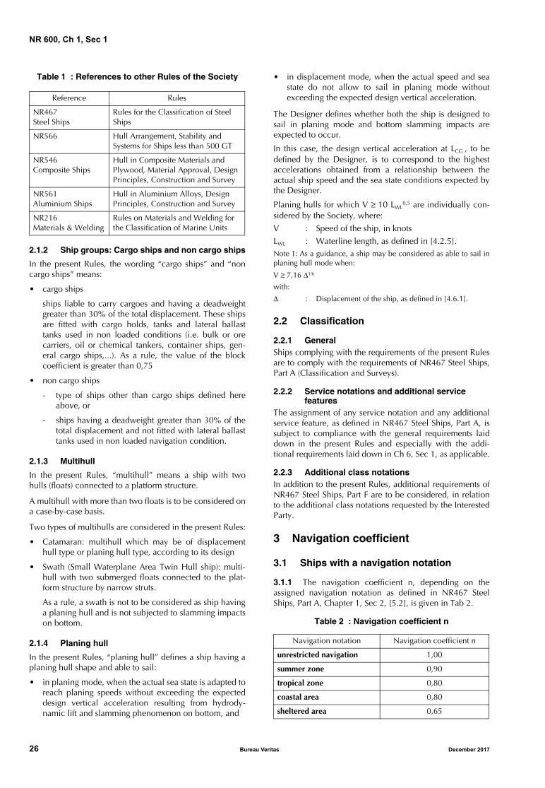
Table 1 : References to other Rules of the Society
2.1.2 Ship groups: Cargo ships and non cargo ships
In the present Rules, the wording “cargo ships” and “noncargo ships” means:
• cargo ships
ships liable to carry cargoes and having a deadweightgreater than 30% of the total displacement. These shipsare fitted with cargo holds, tanks and lateral ballasttanks used in non loaded conditions (i.e. bulk or orecarriers, oil or chemical tankers, container ships, gen-eral cargo ships,...). As a rule, the value of the blockcoefficient is greater than 0,75
• non cargo ships
- type of ships other than cargo ships defined hereabove, or
- ships having a deadweight greater than 30% of thetotal displacement and not fitted with lateral ballasttanks used in non loaded navigation condition.
2.1.3 Multihull
In the present Rules, “multihull” means a ship with twohulls (floats) connected to a platform structure.
A multihull with more than two floats is to be considered ona case-by-case basis.
Two types of multihulls are considered in the present Rules:
• Catamaran: multihull which may be of displacementhull type or planing hull type, according to its design
• Swath (Small Waterplane Area Twin Hull ship): multi-hull with two submerged floats connected to the plat-form structure by narrow struts.
As a rule, a swath is not to be considered as ship havinga planing hull and is not subjected to slamming impactson bottom.
2.1.4 Planing hull
In the present Rules, “planing hull” defines a ship having aplaning hull shape and able to sail:
• in planing mode, when the actual sea state is adapted toreach planing speeds without exceeding the expecteddesign vertical acceleration resulting from hydrody-namic lift and slamming phenomenon on bottom, and
• in displacement mode, when the actual speed and seastate do not allow to sail in planing mode withoutexceeding the expected design vertical acceleration.
The Designer defines whether both the ship is designed tosail in planing mode and bottom slamming impacts areexpected to occur.
In this case, the design vertical acceleration at LCG , to bedefined by the Designer, is to correspond to the highestaccelerations obtained from a relationship between theactual ship speed and the sea state conditions expected bythe Designer.
Planing hulls for which V ≥ 10 LWL0,5 are individually con-
sidered by the Society, where:
V : Speed of the ship, in knots
LWL : Waterline length, as defined in [4.2.5].Note 1: As a guidance, a ship may be considered as able to sail inplaning hull mode when:
V ≥ 7,16 Δ1/6
with:
Δ : Displacement of the ship, as defined in [4.6.1].
2.2 Classification
2.2.1 GeneralShips complying with the requirements of the present Rulesare to comply with the requirements of NR467 Steel Ships,Part A (Classification and Surveys).
2.2.2 Service notations and additional service features
The assignment of any service notation and any additionalservice feature, as defined in NR467 Steel Ships, Part A, issubject to compliance with the general requirements laiddown in the present Rules and especially with the addi-tional requirements laid down in Ch 6, Sec 1, as applicable.
2.2.3 Additional class notationsIn addition to the present Rules, additional requirements ofNR467 Steel Ships, Part F are to be considered, in relationto the additional class notations requested by the InterestedParty.
3 Navigation coefficient
3.1 Ships with a navigation notation
3.1.1 The navigation coefficient n, depending on theassigned navigation notation as defined in NR467 SteelShips, Part A, Chapter 1, Sec 2, [5.2], is given in Tab 2.
Table 2 : Navigation coefficient n
Reference Rules
NR467 Steel Ships
Rules for the Classification of Steel Ships
NR566 Hull Arrangement, Stability and Systems for Ships less than 500 GT
NR546 Composite Ships
Hull in Composite Materials and Plywood, Material Approval, Design Principles, Construction and Survey
NR561 Aluminium Ships
Hull in Aluminium Alloys, Design Principles, Construction and Survey
NR216 Materials & Welding
Rules on Materials and Welding for the Classification of Marine Units
Navigation notation Navigation coefficient n
unrestricted navigation 1,00
summer zone 0,90
tropical zone 0,80
coastal area 0,80
sheltered area 0,65
26 Bureau Veritas December 2017
NR 600, Ch 1, Sec 1
3.2 Sea going launch and launch
3.2.1 For ships having the service notation sea goinglaunch or launch, as defined in NR467 Steel Ships, Part A,Chapter 1, Sec 2, [4.15.2], the navigation coefficient n is asgiven in Tab 3.
Table 3 : Navigation coefficient n
4 Definitions
4.1 Moulded base line
4.1.1 The moulded base line is the horizontal line locatedat the upper face of the bottom plating or at the intersectionbetween the upper face of the bottom plating and the solidbar keel.
For ships designed with a rake of keel, the base line is to beas defined above, at a point located at the midship section.
4.2 Lengths
4.2.1 Rule length LThe rule length L is the distance, in m, measured on thesummer load waterline, from the fore side of the stem to theafter side of the rudder post, or to the centre of the rudderstock where there is no rudder post.
L is to be taken not less than 96%, and need not exceed97%, of the extreme length on the summer load waterline.
4.2.2 Ends of the rule lengthThe fore end (FP) of the rule length L is the perpendicular tothe summer load waterline at the fore side of the stem.
The aft end (AP) of the rule length L is the perpendicular tothe summer load waterline at a distance L aft of FP.
4.2.3 Midship LCG
The midship LCG is the perpendicular to the summer loadwaterline at a distance 0,5 L aft of FP.
4.2.4 Hull length LHULL
The hull length LHULL is equal to the distance, in m, meas-ured from the fore end of the hull to the aft end of the hull.
4.2.5 Waterline length LWL
The waterline length LWL is equal to the distance, in m,measured from the intersection between the waterline atfull load displacement and the fore end of the hull to the aftend of the hull.
4.2.6 Length Lw
The length Lw is to be taken equal to:
Lw = 0,5 (LWL + LHULL)
4.3 Breadth
4.3.1 Moulded breadth BThe moulded breadth B is the greatest moulded breadth, inm, measured amidships below the weather deck.
4.3.2 Waterline breadths BWL and BST
The waterline breadth BWL is the breadth of the hull, in m,measured amidships at the moulded draught.
For a catamaran, the waterline breadth BWL is to be meas-ured amidships at one float, at moulded draught.
For a swath, the waterline breadth BST is to be measuredamidships at one strut, at moulded draught.
4.3.3 Breadth BE between multihull floatsThe breadth BE between the floats of a multihull is the dis-tance, in m, measured between the longitudinal planes ofsymmetry of the floats. As a rule, the longitudinal plane ofsymmetry of a float is located at 0,5 BWL or 0,5 BST.
4.3.4 Breadth BSF of swath submerged floatThe moulded breadth BSF of a swath submerged float is thegreatest moulded breadth of the submerged float, in m,measured amidships.
4.4 Depth D
4.4.1 The depth D is the distance, in m, measured verti-cally on the midship transverse section, from the mouldedbase line to the top of the deck beam at side on the upper-most continuous deck.In the case of ships with a solid bar keel, the moulded baseline is to be taken at the intersection between the upperface of the bottom plating and the solid bar keel at midshipLCG .
4.5 Moulded draught T
4.5.1 The moulded draught T is the distance, in m, meas-ured vertically on the midship transverse section, from themoulded base line to the summer load waterline.In the case of ships with a solid bar keel, the moulded baseline is to be taken as defined in [4.4.1].
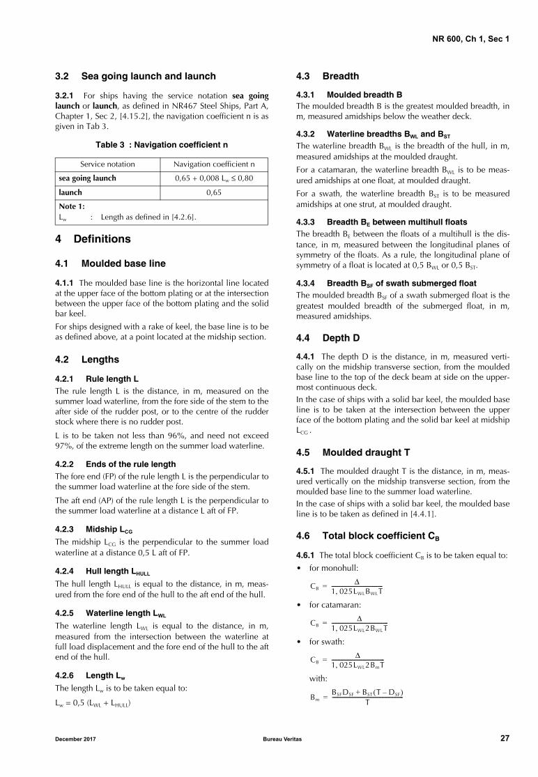
4.6 Total block coefficient CB
4.6.1 The total block coefficient CB is to be taken equal to:
• for monohull:
• for catamaran:
• for swath:
with:
Service notation Navigation coefficient n
sea going launch 0,65 + 0,008 Lw ≤ 0,80
launch 0,65
Note 1: Lw : Length as defined in [4.2.6].
CBΔ
1 025LWLBWLT,---------------------------------------=
CBΔ
1 025LWL2BWLT,-------------------------------------------=
CBΔ
1 025LWL2BmT,----------------------------------------=
BmBSFDSF BST T DSF–( )+
T------------------------------------------------------=
December 2017 Bureau Veritas 27
NR 600, Ch 1, Sec 1
where:
Δ : Moulded displacement, in tonnes, at draught T,in sea water (density ρ = 1,025 t/m2)
LWL : Waterline length, in m, as defined in [4.2.5]
BWL , BSF , BST :Breadths, in m, measured amidships, asdefined in [4.3.2] and [4.3.4]
DSF : Depth, in m, of the submerged float amidships
T : Moulded draught, as defined in [4.5.1].
4.7 Chine and bottom
4.7.1 Chine
For hulls without a clearly identified chine, the chine is thehull point where the tangent to the hull is inclined by 50°compared to the horizontal.
4.7.2 Bottom
The bottom is the part of the hull between the centre line ofthe hull or the float and the chines.
4.8 Lightweight
4.8.1 The lightweight is the displacement, in t, withoutcargo, fuel, lubricating oil, ballast water, fresh water andfeed water, consumable stores and passengers and crewand their effects, but including liquids in piping.
4.9 Deadweight
4.9.1 The deadweight is the difference, in t, between thedisplacement, at the summer draught in sea water of densityρ = 1,025 t/m3, and the lightweight.
4.10 Freeboard deck
4.10.1 The freeboard deck is defined in Regulation 3 of the1966 International Convention on Load Lines, as amended.
4.11 Bulkhead deck
4.11.1 The bulkhead deck in a passenger ship means theuppermost deck at any point in the subdivision length LS towhich the main bulkheads and the ship shell are carriedwatertight. In a cargo ship, the freeboard deck may be takenas the bulkhead deck.
Note 1: The subdivision LS of a ship is the greatest projectedmoulded length of that part of the ship at or below deck or deckslimiting the vertical extent of flooding with the ship at the deepestsubdivision draught.
4.12 Superstructure
4.12.1 General
A superstructure is a decked structure connected to the free-board deck, extending from side to side of the ship or withthe side plating not being inboard of the shell plating morethan 0,04 B.
4.12.2 Superstructure deck
A superstructure deck is a deck forming the upper boundaryof a superstructure.
4.12.3 Deckhouse
A deckhouse is a decked structure other than a superstruc-ture, located on the freeboard deck or above.
4.12.4 Standard height of superstructure hS
The standard height of superstructure hS is defined in Tab 4.
Table 4 : Standard height of superstructure hS
4.12.5 Tiers of superstructures and deckhouses
The lowest tier is the tier located immediately above thefreeboard deck.
The second tier is the tier located immediately above thelowest tier, and so on.
4.13 Multihull platform
4.13.1 A multihull platform is a strength structure connect-ing the hulls by primary transverse cross structure elements.These transverse elements may be cross beams or crossbulkheads.
The part of the platform directly exposed to sea effect isdesigned as platform bottom.
The upper part of the platform together with the upperdecks are defined as platform deck.
5 Reference co-ordinate system
5.1 General
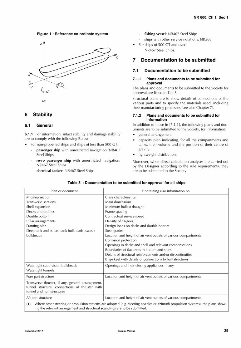
5.1.1 The ship’s geometry, motions, accelerations and loadsare defined with respect to the following right-hand co-ordi-nate system (see Fig 1):
• Origin: at the intersection between the longitudinal planeof symmetry of ship, the aft end of L and the baseline
• X axis: longitudinal axis, positive forwards
• Y axis: transverse axis, positive towards portside
• Z axis: vertical axis, positive upwards.
5.1.2 Positive rotations are oriented in anti-clockwisedirection about the X, Y and Z axes.
Load line length LLL ,
in m
Standard height hS, in m
Raised quarterdeck
All othersuperstructures
LLL ≤ 30 0,90 1,80
30 < LLL < 75 0,9 + 0,00667 (LLL − 30) 1,80
75 ≤ LLL < 90 1,2 + 0,012 (LLL − 75) 1,8 + 0,01 (LLL − 75)
28 Bureau Veritas December 2017
NR 600, Ch 1, Sec 1
Figure 1 : Reference co-ordinate system
6 Stability
6.1 General
6.1.1 For information, intact stability and damage stabilityare to comply with the following Rules:
• For non-propelled ships and ships of less than 500 GT:
- passenger ship with unrestricted navigation: NR467Steel Ships
- ro-ro passenger ship with unrestricted navigation:NR467 Steel Ships
- chemical tanker: NR467 Steel Ships
- fishing vessel: NR467 Steel Ships- ships with other service notations: NR566
• For ships of 500 GT and over:NR467 Steel Ships.
7 Documentation to be submitted
7.1 Documentation to be submitted
7.1.1 Plans and documents to be submitted for approval
The plans and documents to be submitted to the Society forapproval are listed in Tab 5.
Structural plans are to show details of connections of thevarious parts and to specify the materials used, includingtheir manufacturing processes (see also Chapter 7).
7.1.2 Plans and documents to be submitted for information
In addition to those in [7.1.1], the following plans and doc-uments are to be submitted to the Society, for information:• general arrangement• capacity plan indicating, for all the compartments and
tanks, their volume and the position of their centre ofgravity
• lightweight distribution.
Moreover, when direct calculation analyses are carried outby the Designer according to the rule requirements, theyare to be submitted to the Society.
Table 5 : Documentation to be submitted for approval for all ships
�
�
��
�
Plan or document Containing also information on
Midship sectionTransverse sectionsShell expansionDecks and profilesDouble bottomPillar arrangementsFraming planDeep tank and ballast tank bulkheads, swashbulkheads
Class characteristicsMain dimensionsMinimum ballast draughtFrame spacingContractual service speedDensity of cargoesDesign loads on decks and double bottomSteel gradesLocation and height of air vent outlets of various compartmentsCorrosion protectionOpenings in decks and shell and relevant compensationsBoundaries of flat areas in bottom and sidesDetails of structural reinforcements and/or discontinuitiesBilge keel with details of connections to hull structures
Watertight subdivision bulkheadsWatertight tunnels
Openings and their closing appliances, if any
Fore part structure Location and height of air vent outlets of various compartments
Transverse thruster, if any, general arrangement,tunnel structure, connections of thruster withtunnel and hull structures
Aft part structure Location and height of air vent outlets of various compartments
(1) Where other steering or propulsion systems are adopted (e.g. steering nozzles or azimuth propulsion systems), the plans show-ing the relevant arrangement and structural scantlings are to be submitted.
December 2017 Bureau Veritas 29
NR 600, Ch 1, Sec 1
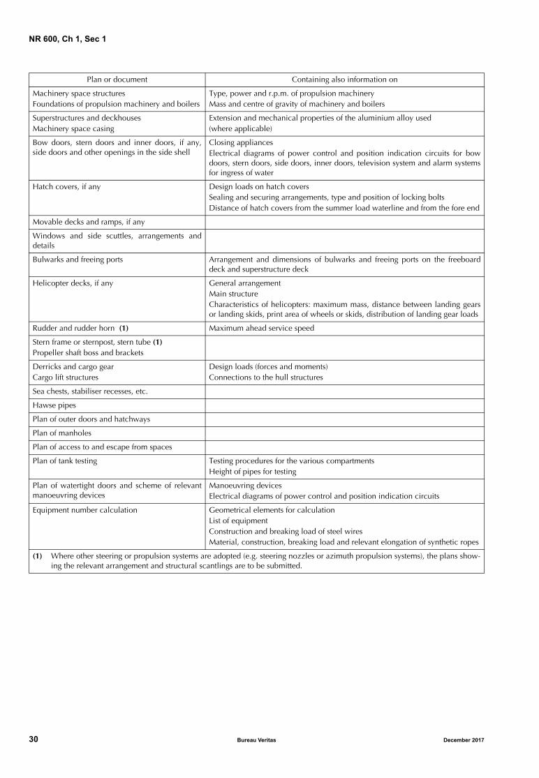
Machinery space structuresFoundations of propulsion machinery and boilers
Type, power and r.p.m. of propulsion machineryMass and centre of gravity of machinery and boilers
Superstructures and deckhousesMachinery space casing
Extension and mechanical properties of the aluminium alloy used (where applicable)
Bow doors, stern doors and inner doors, if any,side doors and other openings in the side shell
Closing appliancesElectrical diagrams of power control and position indication circuits for bowdoors, stern doors, side doors, inner doors, television system and alarm systemsfor ingress of water
Hatch covers, if any Design loads on hatch coversSealing and securing arrangements, type and position of locking boltsDistance of hatch covers from the summer load waterline and from the fore end
Movable decks and ramps, if any
Windows and side scuttles, arrangements anddetails
Bulwarks and freeing ports Arrangement and dimensions of bulwarks and freeing ports on the freeboarddeck and superstructure deck
Helicopter decks, if any General arrangementMain structureCharacteristics of helicopters: maximum mass, distance between landing gearsor landing skids, print area of wheels or skids, distribution of landing gear loads
Rudder and rudder horn (1) Maximum ahead service speed
Stern frame or sternpost, stern tube (1)Propeller shaft boss and brackets
Derricks and cargo gearCargo lift structures
Design loads (forces and moments)Connections to the hull structures
Sea chests, stabiliser recesses, etc.
Hawse pipes
Plan of outer doors and hatchways
Plan of manholes
Plan of access to and escape from spaces
Plan of tank testing Testing procedures for the various compartmentsHeight of pipes for testing
Plan of watertight doors and scheme of relevantmanoeuvring devices
Manoeuvring devicesElectrical diagrams of power control and position indication circuits
Equipment number calculation Geometrical elements for calculationList of equipmentConstruction and breaking load of steel wiresMaterial, construction, breaking load and relevant elongation of synthetic ropes
Plan or document Containing also information on
(1) Where other steering or propulsion systems are adopted (e.g. steering nozzles or azimuth propulsion systems), the plans show-ing the relevant arrangement and structural scantlings are to be submitted.
30 Bureau Veritas December 2017
NR 600, Ch 1, Sec 2
SECTION 2 MATERIALS
1 General
1.1 Application
1.1.1 This Section defines the main characteristics to takeinto account for steels, aluminium alloys or compositematerials within the scope of the determination of the hullscantling as defined in the present Rules.
1.1.2 Materials and products such as parts made of ironcastings, where allowed, products made of copper and cop-per alloys, rivets, anchors, chain cables, cranes, masts, der-rick posts, derricks, accessories and wire ropes are tocomply with the applicable requirements of NR216 Materi-als and Welding.
1.1.3 Materials with different characteristics may beconsidered, provided their specification (manufacture,chemical composition, mechanical properties, welding,...)is submitted to the Society for approval.
2 Steels for hull structure
2.1 General
2.1.1 Characteristics of materials
The characteristics of steels to be used in the construction ofships are to comply with the applicable requirements ofNR216 Materials and Welding.
2.1.2 Testing and manufacturing process
Materials are to be tested in compliance with the applicablerequirements of NR216 Materials and Welding.
The requirements of this Section presume that welding andother cold or hot manufacturing processes (parent materialtypes and welding, preheating, heat treatment after weld-ing,...) are carried out in compliance with current soundworking practices and the applicable requirements ofNR216 Materials and Welding.
2.1.3 Mechanical characteristics of hull steels
The mechanical characteristics of steels are to comply withthe requirements of NR467 Steel Ships, Pt B, Ch 4, Sec 1, inparticular the mechanical characteristics of:
• the grade of steel used for the various strength membersof the structure
• the steels for forging and casting.
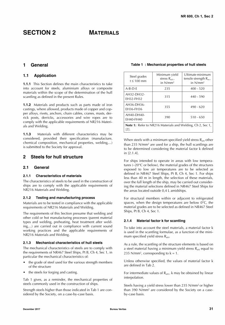
Tab 1 gives, as a reminder, the mechanical properties ofsteels commonly used in the construction of ships.
Strength steels higher than those indicated in Tab 1 are con-sidered by the Society, on a case-by-case basis.
Table 1 : Mechanical properties of hull steels
When steels with a minimum specified yield stress ReH otherthan 235 N/mm2 are used for a ship, the hull scantlings areto be determined considering the material factor k definedin [2.1.4].
For ships intended to operate in areas with low tempera-tures (−20°C or below), the material grades of the structuresexposed to low air temperatures are to be selected asdefined in NR467 Steel Ships, Pt B, Ch 4, Sec 1. For shipsless than 40 m in length, the selection of these materials,over the full length of the ship, may be carried out consider-ing the material selections defined in NR467 Steel Ships forthe areas located outside 0,4 L amidships.
For structural members within or adjacent to refrigeratedspaces, when the design temperatures are below 0°C, thematerial grades are to be selected as defined in NR467 SteelShips, Pt B, Ch 4, Sec 1.
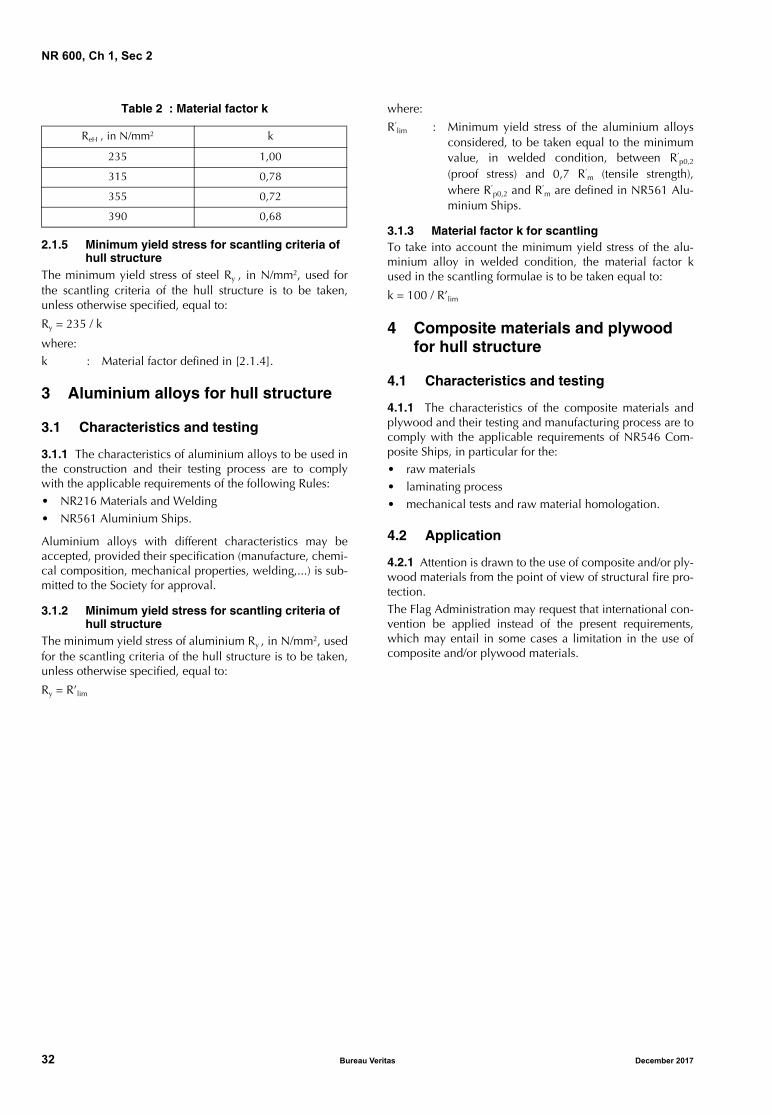
2.1.4 Material factor k for scantling
To take into account the steel materials, a material factor kis used in the scantling formulae, as a function of the mini-mum specified yield stress ReH.
As a rule, the scantling of the structure elements is based ona steel material having a minimum yield stress ReH equal to235 N/mm2, corresponding to k = 1.
Unless otherwise specified, the values of material factor kare defined in Tab 2.
For intermediate values of ReH , k may be obtained by linearinterpolation.
Steels having a yield stress lower than 235 N/mm2 or higherthan 390 N/mm2 are considered by the Society on a case-by-case basis.
Steel gradest ≤ 100 mm
Minimum yield stress ReH ,in N/mm2
Ultimate minimum tensile strength Rm ,
in N/mm2
A-B-D-E 235 400 - 520
AH32-DH32-EH32-FH32
315 440 - 590
AH36-DH36-EH36-FH36
355 490 - 620
AH40-DH40-EH40-FH40
390 510 - 650
Note 1: Refer to NR216 Materials and Welding, Ch 2, Sec 1,[2].
December 2017 Bureau Veritas 31
NR 600, Ch 1, Sec 2
Table 2 : Material factor k
2.1.5 Minimum yield stress for scantling criteria of hull structure
The minimum yield stress of steel Ry , in N/mm2, used forthe scantling criteria of the hull structure is to be taken,unless otherwise specified, equal to:
Ry = 235 / k
where:k : Material factor defined in [2.1.4].
3 Aluminium alloys for hull structure
3.1 Characteristics and testing
3.1.1 The characteristics of aluminium alloys to be used inthe construction and their testing process are to complywith the applicable requirements of the following Rules:• NR216 Materials and Welding• NR561 Aluminium Ships.
Aluminium alloys with different characteristics may beaccepted, provided their specification (manufacture, chemi-cal composition, mechanical properties, welding,...) is sub-mitted to the Society for approval.
3.1.2 Minimum yield stress for scantling criteria of hull structure
The minimum yield stress of aluminium Ry , in N/mm2, usedfor the scantling criteria of the hull structure is to be taken,unless otherwise specified, equal to:
Ry = R’lim
where:
R’lim : Minimum yield stress of the aluminium alloys
considered, to be taken equal to the minimumvalue, in welded condition, between R’
p0,2
(proof stress) and 0,7 R’m (tensile strength),
where R’p0,2 and R’
m are defined in NR561 Alu-minium Ships.
3.1.3 Material factor k for scantlingTo take into account the minimum yield stress of the alu-minium alloy in welded condition, the material factor kused in the scantling formulae is to be taken equal to:
k = 100 / R’lim
4 Composite materials and plywood for hull structure
4.1 Characteristics and testing
4.1.1 The characteristics of the composite materials andplywood and their testing and manufacturing process are tocomply with the applicable requirements of NR546 Com-posite Ships, in particular for the:• raw materials• laminating process• mechanical tests and raw material homologation.
4.2 Application
4.2.1 Attention is drawn to the use of composite and/or ply-wood materials from the point of view of structural fire pro-tection. The Flag Administration may request that international con-vention be applied instead of the present requirements,which may entail in some cases a limitation in the use ofcomposite and/or plywood materials.
ReH , in N/mm2 k
235 1,00
315 0,78
355 0,72
390 0,68
32 Bureau Veritas December 2017
NR 600, Ch 1, Sec 3
SECTION 3 SCANTLING PRINCIPLES
Symbols
LWL : Waterline length, in m, as defined in Sec 1,[4.2.5].
1 Main scantling principles
1.1 General
1.1.1 The present Section defines the main scantling princi-ples considered in the present Rules.
1.2 Type of ships
1.2.1 General
The motions and accelerations of a ship are calculated inrelation to its group defined in Sec 1, [2.1.2] (cargo ship ornon cargo ship).
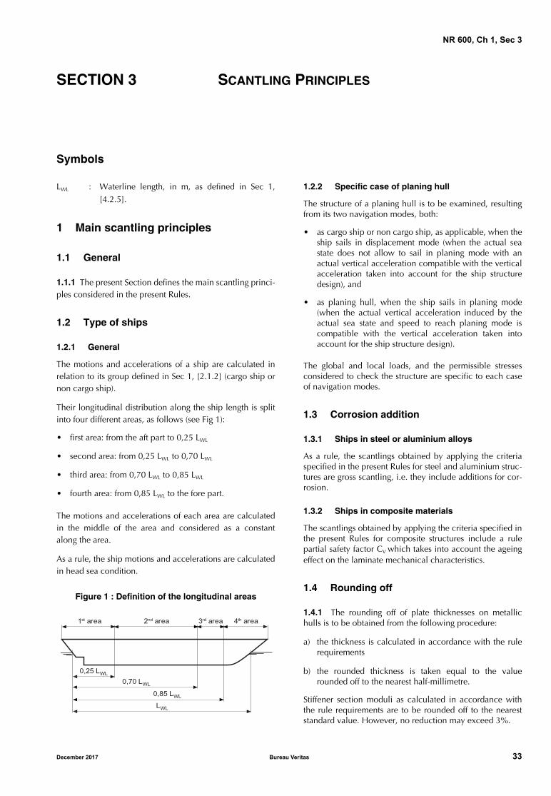
Their longitudinal distribution along the ship length is splitinto four different areas, as follows (see Fig 1):
• first area: from the aft part to 0,25 LWL
• second area: from 0,25 LWL to 0,70 LWL
• third area: from 0,70 LWL to 0,85 LWL
• fourth area: from 0,85 LWL to the fore part.
The motions and accelerations of each area are calculatedin the middle of the area and considered as a constantalong the area.
As a rule, the ship motions and accelerations are calculatedin head sea condition.
Figure 1 : Definition of the longitudinal areas
1.2.2 Specific case of planing hull
The structure of a planing hull is to be examined, resultingfrom its two navigation modes, both:
• as cargo ship or non cargo ship, as applicable, when theship sails in displacement mode (when the actual seastate does not allow to sail in planing mode with anactual vertical acceleration compatible with the verticalacceleration taken into account for the ship structuredesign), and
• as planing hull, when the ship sails in planing mode(when the actual vertical acceleration induced by theactual sea state and speed to reach planing mode iscompatible with the vertical acceleration taken intoaccount for the ship structure design).
The global and local loads, and the permissible stressesconsidered to check the structure are specific to each caseof navigation modes.
1.3 Corrosion addition
1.3.1 Ships in steel or aluminium alloys
As a rule, the scantlings obtained by applying the criteriaspecified in the present Rules for steel and aluminium struc-tures are gross scantling, i.e. they include additions for cor-rosion.
1.3.2 Ships in composite materials
The scantlings obtained by applying the criteria specified inthe present Rules for composite structures include a rulepartial safety factor CV which takes into account the ageingeffect on the laminate mechanical characteristics.
1.4 Rounding off
1.4.1 The rounding off of plate thicknesses on metallichulls is to be obtained from the following procedure:
a) the thickness is calculated in accordance with the rulerequirements
b) the rounded thickness is taken equal to the valuerounded off to the nearest half-millimetre.
Stiffener section moduli as calculated in accordance withthe rule requirements are to be rounded off to the neareststandard value. However, no reduction may exceed 3%.
LWL
1st area 2nd area 3rd area 4th area
0,25 LWL
0,70 LWL
0,85 LWL
December 2017 Bureau Veritas 33

NR 600, Ch 1, Sec 3
2 Hull analysis approach
2.1 Global hull girder strength and local strength
2.1.1 General
As a rule, the global hull girder strength and the localstrength are examined independently in the present Rules,as follows:
• the longitudinal scantling of the hull girder and thetransverse scantling of the platform of catamaran areexamined on the basis of a maximum permissible stressand a buckling check of the elements contributing to theglobal strength in the cases listed in Ch 4, Sec 2, [1.1.3]
• the local scantling is examined on the basis of the localpermissible stresses defined in relation to the type oflocal loads applied and the type of structure elements.
2.1.2 Particular caseWhen the global stress, in N/mm2, calculated according toCh 4, Sec 2 (excluding the cases of additional specific wavehull girder loads defined in Ch 3, Sec 2, [6]) is greater than0,35 Ry , the global and local stresses are to be combined tocheck the scantlings of the structure elements contributingto the hull girder strength,
where:Ry : As defined in Sec 2, [2.1.5] for steel structure
and in Sec 2, [3.1.2] for aluminium structure.As a rule, the following requirements are to be fully applied: • NR467 Steel Ships, Part B, Chapter 7, dedicated to ships
greater than 65 m in length, or• Ch 4, App 2 of the present Rules.
For ship built in composite materials, a combination withthe global hull girder stresses for the local scantling analysismay be carried out when deemed necessary by the Society,on a case-by-case basis.
34 Bureau Veritas December 2017
NR 600
Chapter 2
STRUCTURE DESIGN PRINCIPLES,GENERAL ARRANGEMENT AND
SCANTLING CRITERIA
SECTION 1 STRUCTURE DESIGN PRINCIPLES
SECTION 2 SUBDIVISION, COMPARTMENT ARRANGEMENT, AND ARRANGEMENT OF HULL OPENINGS
SECTION 3 SCANTLING CRITERIA
December 2017 Bureau Veritas 35

36 Bureau Veritas December 2017
NR 600, Ch 2, Sec 1
SECTION 1 STRUCTURE DESIGN PRINCIPLES
1 General
1.1 Application
1.1.1 Steel structure
The requirements of the present Section apply to longitudi-nally or transversely framed structure arrangement of hullsbuilt in steel materials for:
• structural continuity of hull
• single and double bottoms
• sides and decks
• transverse and longitudinal structures
• superstructures and deckhouses
• special features.
Any other arrangement may be considered, on a case-by-case basis.
Additional specific structure design principles in relation tothe service notation of the ship are defined in Ch 6, Sec 1.
1.1.2 Aluminium structure
Equivalent arrangement for hulls built in aluminium alloysis defined in NR561 Aluminium Ships.
1.1.3 Composite and plywood structure
Equivalent arrangement for hulls built in composite materi-als and/or plywood is defined in NR546 Composite Ships.
2 Structural continuity of hull girder
2.1 General principles for longitudinal hull girder
2.1.1 Attention is to be paid to the structural continuity:
• in way of changes in the framing system
• at the connections of primary supporting members andsecondary stiffeners.
2.1.2 The longitudinal members contributing to the hullgirder longitudinal strength are to extend continuously overa sufficient distance towards the ends of the ship.
The secondary stiffeners contributing to the hull girder lon-gitudinal strength are generally to be continuous whencrossing primary supporting members. Otherwise, the detailof connections is considered by the Society on a case-by-case basis.
2.1.3 Where stress concentrations may occur in way ofstructural discontinuity, adequate compensation and rein-forcements are to be provided.
2.1.4 Openings are to be avoided, as far as practicable, inway of highly stressed areas.
Where necessary, the shape of openings is to be speciallydesigned to reduce the stress concentration factors.
Openings are to be generally well rounded with smoothedges.
2.1.5 Primary supporting members are to be arranged insuch a way that they ensure adequate continuity of strength.Abrupt changes in height or in cross-section are to beavoided.
2.2 General principles for multihull platform
2.2.1 Attention is to be paid to the structural continuity ofthe primary transverse cross structure of the platform ensur-ing the global transverse resistance of the multihull.
The primary transverse cross structure of catamaran is gen-erally to be continuous when crossing float structures.
The connection between the transverse cross structures ofswath and struts is to be examined by direct calculation.
The general continuity principles defined in [2.1] apply alsoto the primary transverse cross structure of the platform.
2.3 Insert plates and doublers
2.3.1 A local increase in plating thickness is generally to beachieved through insert plates. Local doublers, normallyallowed only for temporary repair, may however beaccepted by the Society on a case-by-case basis.
In any case, doublers and insert plates are to be made ofmaterials of a quality at least equal to the quality of theplates on which they are welded.
2.3.2 Doublers having a width, in mm, greater than:
• 20 times their thickness, for thicknesses equal to or lessthan 15 mm
• 25 times their thickness, for thicknesses greater than15 mm
are to be fitted with slot welds, to be effected according toChapter 6.
2.3.3 When doublers fitted on the outer shell and strengthdeck within 0,6 L amidships are accepted by the Society,their width and thickness are to be such that slot welds arenot necessary according to the requirements in [2.3.2]. Out-side this area, the possibility of fitting doublers requiringslot welds will be considered by the Society on a case-by-case basis.
December 2017 Bureau Veritas 37

NR 600, Ch 2, Sec 1
2.4 Connection between steel and aluminium
2.4.1 Any direct contact between steel and aluminiumalloy is to be avoided.
Any heterogeneous jointing system is considered by theSociety on a case-by-case basis.
The use of transition joints made of aluminium/steel-cladplates or profiles is to be in accordance with NR216 Materi-als and Welding.
3 Bottom structure arrangement
3.1 General arrangement
3.1.1 The bottom structure is to be checked by theDesigner to make sure that it withstands the loads resultingfrom the dry-docking of the ship or the lifting by crane,when applicable. This check under such loading cases isnot within the scope of classification.
3.1.2 Provision is to be made for the free passage of waterfrom all the areas of the bottom to the suctions, by means ofscallops in floors and bottom girders.
3.1.3 Additional girders and floors may be fitted in theengine room to ensure adequate rigidity of the structure,according to the recommendations of the engine supplier.
3.1.4 If fitted, solid ballast is to be securely positioned. Ifnecessary, intermediate girders and floors may be required.The builder is to check that the solid ballast material is com-patible with the hull material.
3.1.5 Where face plates of floors and girders are at thesame level, the face plate of the stiffer member is generallyto be continuous. Butt welds of the face plates are to pro-vide strength continuity.
3.1.6 As a rule, bottom girders are to be fitted in way ofeach line of pillars. If it is not the case, local longitudinalmembers are to be provided.
3.2 Longitudinal framing arrangement of single bottom
3.2.1 As a general rule, hull with a longitudinally framedsingle bottom is to be fitted with a continuous or an inter-coastal centre girder welded to the floors.
3.2.2 Where side girders are fitted locally in lieu of the cen-tre girder, they are to be extended over a sufficient distancebeyond the ends of the centre girder and an additional stiff-ening of the bottom in the centreline area may be required.
3.2.3 Centre and side bottom girders are to be extended asfar as possible towards the ends of the hull.
3.2.4 Cut-outs fitted in the web of floors for the crossing ofbottom longitudinals are to be taken into account for shearanalysis of the floors.
3.3 Transverse framing arrangement of single bottom
3.3.1 Requirements of [3.1] apply also to transversallyframed single bottom.
3.3.2 In general, the height, in m, of the floors at thecentreline should not be less than B/16. In the case of shipswith considerable rise of floors, this height may be requiredto be increased so as to ensure a satisfactory connection tothe frames.
3.3.3 The ends of the floors at side are to be aligned withthe side transverse members.
It may be accepted, on a case-by-case basis, that the floorends at side be welded on a primary longitudinal memberof the side shell or of the bottom.
3.3.4 Openings and cut-outs in the web of bottom girdersfor the crossing of floors are to be taken into account forshear analysis of the floors.
3.4 Double bottom arrangement
3.4.1 Double bottom height
As a general rule, the double bottom height is to be:
• sufficient to ensure access to any part of the bottom, and
• not less than 0,76 m in way of the centre girder.
3.4.2 Where the height of the double bottom varies, thevariation is generally to be made gradually and over an ade-quate length.
The knuckles of inner bottom plating are to be located inway of floors.
Where this arrangement is not possible, suitable longitudi-nal structures such as partial girders, longitudinal bracketsetc., fitted across the knuckle, are to be fitted.
3.4.3 Adequate continuity is to be provided between dou-ble bottom area and single bottom area.
3.4.4 Floors are to be fitted:
• watertight in way of the transverse watertight bulkheads
• reinforced in way of the double bottom steps.
3.4.5 Watertight floors are to be fitted with stiffeners havinga section modulus not less than that required for tank bulk-head vertical stiffeners.
3.4.6 In case of open floors consisting of a frame con-nected to the bottom plating and a reverse frame connectedto the inner bottom plating, the construction principle is tobe as shown in Fig 1.
38 Bureau Veritas December 2017
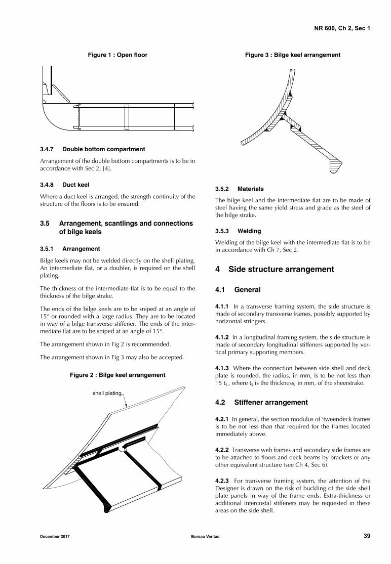
NR 600, Ch 2, Sec 1
Figure 1 : Open floor
3.4.7 Double bottom compartment
Arrangement of the double bottom compartments is to be inaccordance with Sec 2, [4].
3.4.8 Duct keel
Where a duct keel is arranged, the strength continuity of thestructure of the floors is to be ensured.
3.5 Arrangement, scantlings and connections of bilge keels
3.5.1 Arrangement
Bilge keels may not be welded directly on the shell plating.An intermediate flat, or a doubler, is required on the shellplating.
The thickness of the intermediate flat is to be equal to thethickness of the bilge strake.
The ends of the bilge keels are to be sniped at an angle of15° or rounded with a large radius. They are to be locatedin way of a bilge transverse stiffener. The ends of the inter-mediate flat are to be sniped at an angle of 15°.
The arrangement shown in Fig 2 is recommended.
The arrangement shown in Fig 3 may also be accepted.
Figure 2 : Bilge keel arrangement
Figure 3 : Bilge keel arrangement
3.5.2 Materials
The bilge keel and the intermediate flat are to be made ofsteel having the same yield stress and grade as the steel ofthe bilge strake.
3.5.3 Welding
Welding of the bilge keel with the intermediate flat is to bein accordance with Ch 7, Sec 2.
4 Side structure arrangement
4.1 General
4.1.1 In a transverse framing system, the side structure ismade of secondary transverse frames, possibly supported byhorizontal stringers.
4.1.2 In a longitudinal framing system, the side structure ismade of secondary longitudinal stiffeners supported by ver-tical primary supporting members.
4.1.3 Where the connection between side shell and deckplate is rounded, the radius, in mm, is to be not less than15 tS , where tS is the thickness, in mm, of the sheerstrake.
4.2 Stiffener arrangement
4.2.1 In general, the section modulus of ‘tweendeck framesis to be not less than that required for the frames locatedimmediately above.
4.2.2 Transverse web frames and secondary side frames areto be attached to floors and deck beams by brackets or anyother equivalent structure (see Ch 4, Sec 6).
4.2.3 For transverse framing system, the attention of theDesigner is drawn on the risk of buckling of the side shellplate panels in way of the frame ends. Extra-thickness oradditional intercostal stiffeners may be requested in theseareas on the side shell.
shell plating
December 2017 Bureau Veritas 39
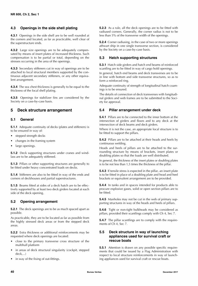
NR 600, Ch 2, Sec 1
4.3 Openings in the side shell plating
4.3.1 Openings in the side shell are to be well rounded atthe corners and located, as far as practicable, well clear ofthe superstructure ends.
4.3.2 Large size openings are to be adequately compen-sated by means of insert plates of increased thickness. Suchcompensation is to be partial or total, depending on thestresses occurring in the area of the openings.
4.3.3 Secondary stiffeners cut in way of openings are to beattached to local structural members supported by the con-tinuous adjacent secondary stiffeners, or any other equiva-lent arrangement.
4.3.4 The sea chest thickness is generally to be equal to thethickness of the local shell plating.
4.3.5 Openings for stabilizer fins are considered by theSociety on a case-by-case basis.
5 Deck structure arrangement
5.1 General
5.1.1 Adequate continuity of decks (plates and stiffeners) isto be ensured in way of:
• stepped strength decks
• changes in the framing system
• large openings.
5.1.2 Deck supporting structures under cranes and wind-lass are to be adequately stiffened.
5.1.3 Pillars or other supporting structures are generally tobe fitted under heavy concentrated loads on decks.
5.1.4 Stiffeners are also to be fitted in way of the ends andcorners of deckhouses and partial superstructures.
5.1.5 Beams fitted at sides of a deck hatch are to be effec-tively supported by at least two deck girders located at eachside of the deck opening.
5.2 Opening arrangement
5.2.1 The deck openings are to be as much spaced apart aspossible.
As practicable, they are to be located as far as possible fromthe highly stressed deck areas or from the stepped deckareas.
5.2.2 Extra thickness or additional reinforcements may berequested where deck openings are located:
• close to the primary transverse cross structure of themultihull platform
• in areas of deck structural singularity (cockpit, steppeddeck,...)
• in way of the fixing of out-fittings.
5.2.3 As a rule, all the deck openings are to be fitted withradiused corners. Generally, the corner radius is not to beless than 5% of the transverse width of the openings.
5.2.4 Corner radiusing, in the case of two or more openingsathwart ship in one single transverse section, is consideredby the Society on a case-by-case basis.
5.3 Hatch supporting structures
5.3.1 Hatch side girders and hatch end beams of reinforcedscantling are to be fitted in way of cargo hold openings.
In general, hatch end beams and deck transverses are to bein line with bottom and side transverse structures, so as toform a reinforced ring.
Adequate continuity of strength of longitudinal hatch coam-ings is to be ensured.
The details of connection of deck transverses with longitudi-nal girders and web frames are to be submitted to the Soci-ety for approval.
5.4 Pillar arrangement under deck
5.4.1 Pillars are to be connected to the inner bottom at theintersection of girders and floors and to any deck at theintersection of deck beams and deck girders.
Where it is not the case, an appropriate local structure is tobe fitted to support the pillars.
5.4.2 Pillars are to be attached at their heads and heels bycontinuous welding.
Heads and heels of pillars are to be attached to the sur-rounding structure by means of brackets, insert plates ordoubling plates so that the loads are well distributed.
In general, the thickness of the insert plates or doubling platesis to be not less than 1,5 times the thickness of the pillar.
5.4.3 If tensile stress is expected in the pillar, an insert plateis to be fitted in place of a doubling plate and head and heelbrackets or equivalent arrangement are to be provided.
5.4.4 In tanks and in spaces intended for products able toprocure explosive gases, solid or open section pillars are tobe fitted.
5.4.5 Manholes may not be cut in the web of primary sup-porting structures in way of the heads and heels of pillars.
5.4.6 Tight or non-tight bulkheads may be considered aspillars, provided their scantlings comply with Ch 4, Sec 7.
5.4.7 The pillar scantlings are to comply with the require-ments of Ch 4, Sec 7.
5.5 Deck structure in way of launching appliances used for survival craft or rescue boats
5.5.1 Attention is drawn on any possible specific require-ments that could be issued by a Flag Administration withrespect to local structure reinforcements in way of launch-ing appliances used for survival craft or rescue boats.
40 Bureau Veritas December 2017
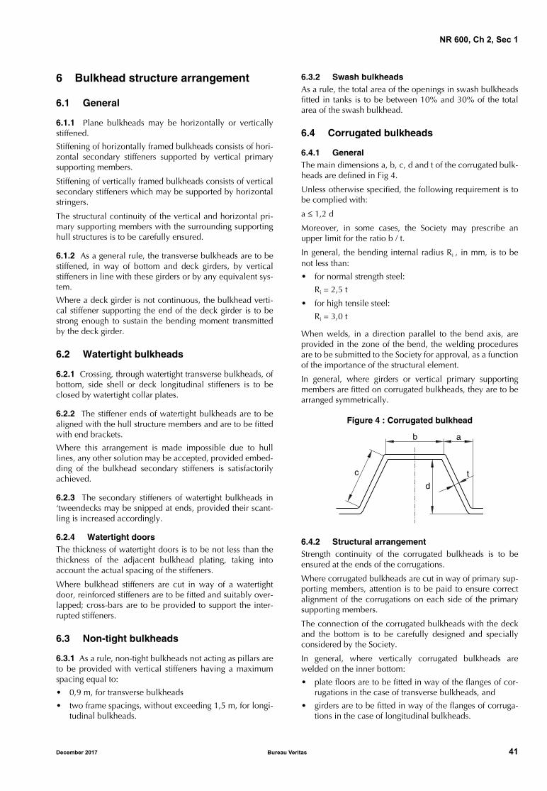
NR 600, Ch 2, Sec 1
6 Bulkhead structure arrangement
6.1 General
6.1.1 Plane bulkheads may be horizontally or verticallystiffened.
Stiffening of horizontally framed bulkheads consists of hori-zontal secondary stiffeners supported by vertical primarysupporting members.
Stiffening of vertically framed bulkheads consists of verticalsecondary stiffeners which may be supported by horizontalstringers.
The structural continuity of the vertical and horizontal pri-mary supporting members with the surrounding supportinghull structures is to be carefully ensured.
6.1.2 As a general rule, the transverse bulkheads are to bestiffened, in way of bottom and deck girders, by verticalstiffeners in line with these girders or by any equivalent sys-tem.
Where a deck girder is not continuous, the bulkhead verti-cal stiffener supporting the end of the deck girder is to bestrong enough to sustain the bending moment transmittedby the deck girder.
6.2 Watertight bulkheads
6.2.1 Crossing, through watertight transverse bulkheads, ofbottom, side shell or deck longitudinal stiffeners is to beclosed by watertight collar plates.
6.2.2 The stiffener ends of watertight bulkheads are to bealigned with the hull structure members and are to be fittedwith end brackets.
Where this arrangement is made impossible due to hulllines, any other solution may be accepted, provided embed-ding of the bulkhead secondary stiffeners is satisfactorilyachieved.
6.2.3 The secondary stiffeners of watertight bulkheads in‘tweendecks may be snipped at ends, provided their scant-ling is increased accordingly.
6.2.4 Watertight doorsThe thickness of watertight doors is to be not less than thethickness of the adjacent bulkhead plating, taking intoaccount the actual spacing of the stiffeners.
Where bulkhead stiffeners are cut in way of a watertightdoor, reinforced stiffeners are to be fitted and suitably over-lapped; cross-bars are to be provided to support the inter-rupted stiffeners.
6.3 Non-tight bulkheads
6.3.1 As a rule, non-tight bulkheads not acting as pillars areto be provided with vertical stiffeners having a maximumspacing equal to:
• 0,9 m, for transverse bulkheads
• two frame spacings, without exceeding 1,5 m, for longi-tudinal bulkheads.
6.3.2 Swash bulkheadsAs a rule, the total area of the openings in swash bulkheadsfitted in tanks is to be between 10% and 30% of the totalarea of the swash bulkhead.
6.4 Corrugated bulkheads
6.4.1 GeneralThe main dimensions a, b, c, d and t of the corrugated bulk-heads are defined in Fig 4.
Unless otherwise specified, the following requirement is tobe complied with:
a ≤ 1,2 d
Moreover, in some cases, the Society may prescribe anupper limit for the ratio b / t.
In general, the bending internal radius Ri , in mm, is to benot less than:
• for normal strength steel:
Ri = 2,5 t
• for high tensile steel:
Ri = 3,0 t
When welds, in a direction parallel to the bend axis, areprovided in the zone of the bend, the welding proceduresare to be submitted to the Society for approval, as a functionof the importance of the structural element.
In general, where girders or vertical primary supportingmembers are fitted on corrugated bulkheads, they are to bearranged symmetrically.
Figure 4 : Corrugated bulkhead
6.4.2 Structural arrangementStrength continuity of the corrugated bulkheads is to beensured at the ends of the corrugations.
Where corrugated bulkheads are cut in way of primary sup-porting members, attention is to be paid to ensure correctalignment of the corrugations on each side of the primarysupporting members.
The connection of the corrugated bulkheads with the deckand the bottom is to be carefully designed and speciallyconsidered by the Society.
In general, where vertically corrugated bulkheads arewelded on the inner bottom:
• plate floors are to be fitted in way of the flanges of cor-rugations in the case of transverse bulkheads, and
• girders are to be fitted in way of the flanges of corruga-tions in the case of longitudinal bulkheads.
b
c
d
a
t
December 2017 Bureau Veritas 41
NR 600, Ch 2, Sec 1
However, other arrangements ensuring adequate structuralcontinuity may be accepted by the Society.
In general, the upper and lower parts of horizontally corru-gated bulkheads are to be flat over a depth equal to 0,1 D.
Where stools are fitted at the lower part of transverse bulk-heads, the thickness of the adjacent plate floors is to be notless than that of the stool plating.
6.4.3 Bulkhead stool
In general, plate diaphragms or web frames are to be fittedin bottom stools in way of the double bottom longitudinalgirders or plate floors, as the case may be.
Brackets or deep webs are to be fitted to connect the upperstool to the deck transverses or hatch end beams, as thecase may be.
The continuity of the corrugated bulkhead with the stoolplating is to be adequately ensured. In particular, the upperstrake of the lower stool is to be of the same thickness andyield stress as those of the lower strake of the bulkhead.
6.5 Bulkheads acting as pillars
6.5.1 As a rule, bulkheads acting as pillars (i.e. thosedesigned to sustain the loads transmitted by a deck struc-ture) are to be provided with vertical stiffeners spaced, at amaximum, two frames apart.
6.5.2 A vertical stiffening member is to be fitted on thebulkhead in line with the deck supporting member transfer-ring the loads from the deck and is to be checked as definedin Ch 4, Sec 7.
6.6 Bracketed stiffeners
6.6.1 The bracket scantlings at ends of bulkhead stiffenersare to be defined by direct calculation, taking into accountthe bending moment and shear forces acting on the stiffenerin way of the bracket as defined in Ch 4, Sec 6.
7 Superstructures and deckhouses
7.1 Connection of superstructures and deckhouses with the hull structure
7.1.1 Superstructure and deckhouse frames are to be fitted,as far as practicable, in way of deck frame structure and areto be efficiently connected.
Ends of superstructures and deckhouses are to be efficientlysupported by bulkheads, diaphragms, webs or pillars.
Where hatchways are fitted close to the superstructure ends,additional strengthening may be required.
7.1.2 Construction details
The vertical stiffeners of the superstructure and deckhousewalls of the first tier (directly located above the freeboarddeck) are to be attached to the decks at their ends.
Brackets are to be fitted at the lower end, and preferablyalso the upper end, of the vertical stiffeners of the exposedfront bulkheads of engine casings and superstructures.
7.1.3 Connection to the hull deck of the corners of super-structures and deckhouses is considered by the Society on acase-by-case basis. Where necessary, local reinforcementsmay be required.
7.1.4 As a general rules, the side plating at ends of super-structures is to be tapered into the side shell bulwark or thesheerstrake of the strength deck.
Where a raised deck is fitted, the local reinforcement in wayof the step is to extend, as a general rule, over at least three-frame spacings.
7.2 Structural arrangement of superstructures and deckhouses
7.2.1 Web frames, transverse partial bulkheads or otherequivalent strengthening of each tier (superstructure anddeckhouses) are to be arranged, where practicable, in linewith the transverse reinforced structure below.
Web frames are also to be arranged in way of the largeopenings, tender davits, winches, provision cranes andother areas subjected to local loads.
Web frames, pillars, partial bulkheads and similar strength-ening are to be arranged, in conjunction with the decktransverses, at ends of superstructures and deckhouses.
7.2.2 Openings
The arrangement of superstructure and deckhouse openingsis to be as defined in Ch 5, Sec 1.
The attention of the Shipowners, Shipyards and Designer isdrawn on the fact that the Flag Administration may requestthe application of National Rules.
7.2.3 Access openings and doors
Access openings cut in side bulkheads of enclosed super-structures are to be fitted with doors having a strengthequivalent to the strength of the surrounding structure.
Special consideration is to be given to the connection of thedoors to the surrounding structure.
Securing devices which ensure watertightness are toinclude tight gaskets, clamping dogs or other similar appli-ances, and are to be permanently attached to the bulkheadsand doors. These doors are to be operable from both sides.
42 Bureau Veritas December 2017
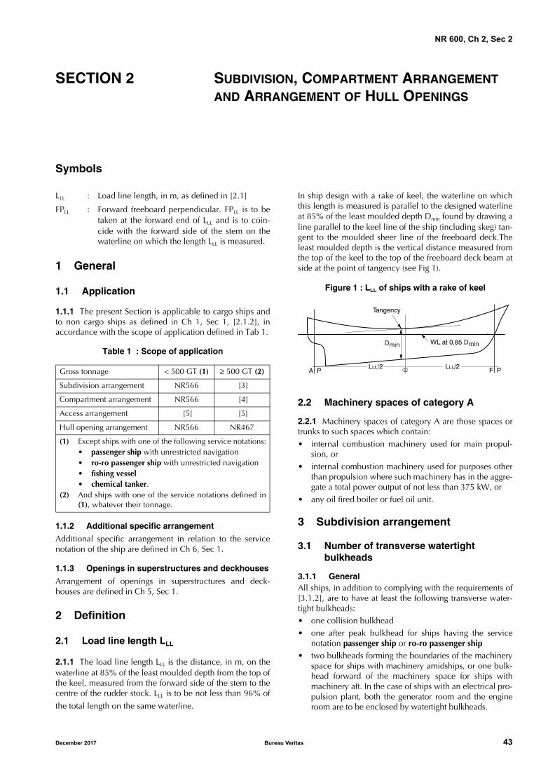
NR 600, Ch 2, Sec 2
SECTION 2 SUBDIVISION, COMPARTMENT ARRANGEMENT AND ARRANGEMENT OF HULL OPENINGS
Symbols
LLL : Load line length, in m, as defined in [2.1]
FPLL : Forward freeboard perpendicular. FPLL is to betaken at the forward end of LLL and is to coin-cide with the forward side of the stem on thewaterline on which the length LLL is measured.
1 General
1.1 Application
1.1.1 The present Section is applicable to cargo ships andto non cargo ships as defined in Ch 1, Sec 1, [2.1.2], inaccordance with the scope of application defined in Tab 1.
Table 1 : Scope of application
1.1.2 Additional specific arrangement
Additional specific arrangement in relation to the servicenotation of the ship are defined in Ch 6, Sec 1.
1.1.3 Openings in superstructures and deckhouses
Arrangement of openings in superstructures and deck-houses are defined in Ch 5, Sec 1.
2 Definition
2.1 Load line length LLL
2.1.1 The load line length LLL is the distance, in m, on thewaterline at 85% of the least moulded depth from the top ofthe keel, measured from the forward side of the stem to thecentre of the rudder stock. LLL is to be not less than 96% of
the total length on the same waterline.
In ship design with a rake of keel, the waterline on whichthis length is measured is parallel to the designed waterlineat 85% of the least moulded depth Dmin found by drawing aline parallel to the keel line of the ship (including skeg) tan-gent to the moulded sheer line of the freeboard deck.Theleast moulded depth is the vertical distance measured fromthe top of the keel to the top of the freeboard deck beam atside at the point of tangency (see Fig 1).
Figure 1 : LLL of ships with a rake of keel
2.2 Machinery spaces of category A
2.2.1 Machinery spaces of category A are those spaces ortrunks to such spaces which contain: • internal combustion machinery used for main propul-
sion, or• internal combustion machinery used for purposes other
than propulsion where such machinery has in the aggre-gate a total power output of not less than 375 kW, or
• any oil fired boiler or fuel oil unit.
3 Subdivision arrangement
3.1 Number of transverse watertight bulkheads
3.1.1 GeneralAll ships, in addition to complying with the requirements of[3.1.2], are to have at least the following transverse water-tight bulkheads:• one collision bulkhead• one after peak bulkhead for ships having the service
notation passenger ship or ro-ro passenger ship• two bulkheads forming the boundaries of the machinery
space for ships with machinery amidships, or one bulk-head forward of the machinery space for ships withmachinery aft. In the case of ships with an electrical pro-pulsion plant, both the generator room and the engineroom are to be enclosed by watertight bulkheads.
Gross tonnage < 500 GT (1) ≥ 500 GT (2)
Subdivision arrangement NR566 [3]
Compartment arrangement NR566 [4]
Access arrangement [5] [5]
Hull opening arrangement NR566 NR467
(1) Except ships with one of the following service notations:• passenger ship with unrestricted navigation• ro-ro passenger ship with unrestricted navigation• fishing vessel• chemical tanker.
(2) And ships with one of the service notations defined in(1), whatever their tonnage.
� �� �
������
� �� ���� ��������
�� ��
December 2017 Bureau Veritas 43
NR 600, Ch 2, Sec 2
3.1.2 Additional bulkheads
As a rule, for ships not required to comply with subdivisionregulations, the number of transverse bulkheads adequatelyspaced are to be at least as indicated in Tab 2.
Additional bulkheads may be required for ships having tocomply with subdivision or damage stability criteria.
Table 2 : Number of transverse bulkheads
3.2 Water ingress detection
3.2.1 General
When a ship is fitted, below the freeboard deck, with a sin-gle cargo hold or with cargo holds not separated by at leastone bulkhead made watertight up to the freeboard deck, awater ingress detection system is to be fitted according toNR467 Steel Ships, Pt C, Ch 1, Sec 10, [6.12.2].
3.2.2 Bulk carriers
For ships granted with the service notation bulk carrier,bulk carrier ESP, ore carrier ESP, combination car-rier/OBO ESP or combination carrier/OOC ESP, the wateringress detection system is to be fitted according to NR467Steel Ships, Pt C, Ch 1, Sec 10, [6.12.1].
3.3 Collision bulkhead
3.3.1 A collision bulkhead, made watertight up to the bulk-head deck, is to be fitted. This bulkhead is to be located at adistance from FPLL not less than 5 per cent of the length LLL
and, except as may be permitted by the Society, not morethan 8 per cent of LLL or 5 per cent of LLL + 3 m, whicheveris the greater.
Note 1: For ships not covered by the SOLAS Convention, LLL neednot be taken less than 50 m, unless otherwise required by theNational Authorities.
3.3.2 Where any part of the ship below the waterlineextends forward of the forward perpendicular, e.g. a bul-bous bow, the distances, in metres, stipulated in [3.3.1] areto be measured from a point located either:
• at mid-length of such an extension, or
• at a distance equal to 1,5 per cent of the length LLL for-ward of the forward perpendicular.
3.3.3 The bulkhead may have steps or recesses, providedthey are within the limits specified in [3.3.1] or [3.3.2].
No door, manhole, ventilation duct or any other opening isto be fitted in the collision bulkhead below the bulkheaddeck.
3.3.4 At the Owner’s request and subject to the agreementof the flag Administration, the Society may accept, on acase-by-case basis, a distance from the collision bulkhead
to the forward perpendicular FPLL greater than the maxi-mum limit specified in [3.3.1] and [3.3.2], provided thatsubdivision and stability calculations show that, when theship is in upright condition on full load summer waterline,flooding of the space forward of the collision bulkhead willnot result in any part of the freeboard deck becomingimmersed, or in any unacceptable loss of stability.
In such a case, the attention of the Owner and the Shipyardis drawn to the fact that the flag Administration may imposeadditional requirements and that such an arrangement is, inprinciple, formalised by the issuance of a certificate ofexemption under the SOLAS Convention provisions. More-over, in case of change of flag, the taking Administrationmay not accept the exemption.
3.3.5 Where a long forward superstructure is fitted, the col-lision bulkhead is to be extended weathertight up to the nextdeck above the bulkhead deck. This extension need not befitted directly above the bulkhead below, provided that:
• it is located within the limits specified in [3.3.1] or[3.3.2], considering the exemption given in [3.3.6], and
• the part of the deck which forms the step is made effec-tively weathertight.
3.3.6 Where bow doors are fitted and a sloping loadingramp forms part of the extension of the collision bulkheadabove the freeboard deck, the part of the ramp beyond2,3 m above the freeboard deck may extend forward of thelimit specified in [3.3.1] or [3.3.2]. The ramp is to be weath-ertight over its full length.
3.3.7 The number of openings in the extension of the colli-sion bulkhead above the freeboard deck is to be restrictedto the minimum compatible with the design and normaloperation of the ship. All such openings are to be capable ofbeing closed weathertight.
3.4 After peak bulkheads, machinery space bulkheads and sterntubes
3.4.1 General
Bulkheads are to be fitted to separate the machinery spacefrom the cargo and accommodation spaces forward and aft,and made watertight up to the bulkhead deck. In passengerships, an after peak bulkhead is also to be fitted and madewatertight up to the bulkhead deck. The after peak bulkheadmay, however, be stepped below the bulkhead deck, pro-vided the degree of safety of the ship as regards subdivisionis not thereby impaired.
3.4.2 Sterntubes
In all the cases, sterntubes are to be enclosed in watertightspaces of moderate volume. In passenger ships, the sterngland is to be located in a watertight shaft tunnel or otherwatertight space separate from the sterntube compartmentand of such a volume that, if flooded by leakage through thestern gland, the bulkhead deck will not be immersed. Incargo ships, other measures to minimise the danger of sea-water ingress in case of damage to the sterntube arrange-ment may be taken at the discretion of the Society.
Ship length, in mFor ships with aft machinery
For the other ships
L < 65 3 4
L ≥ 65 4 5
44 Bureau Veritas December 2017
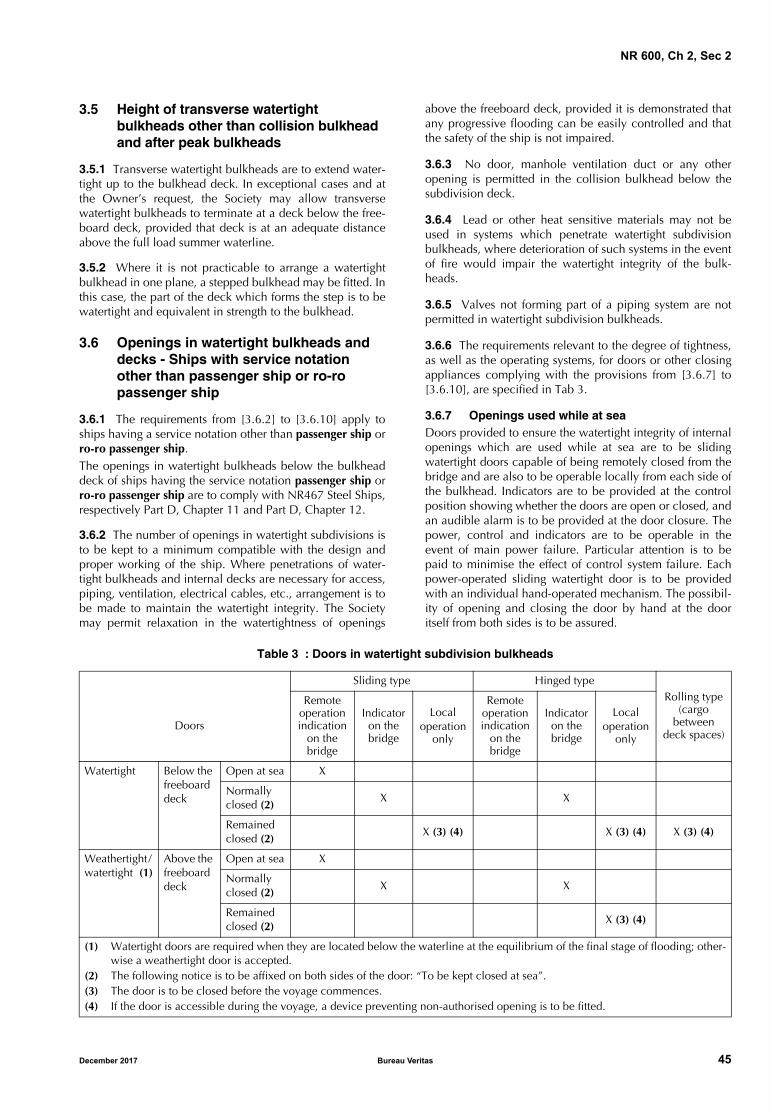
NR 600, Ch 2, Sec 2
3.5 Height of transverse watertight bulkheads other than collision bulkhead and after peak bulkheads
3.5.1 Transverse watertight bulkheads are to extend water-tight up to the bulkhead deck. In exceptional cases and atthe Owner’s request, the Society may allow transversewatertight bulkheads to terminate at a deck below the free-board deck, provided that deck is at an adequate distanceabove the full load summer waterline.
3.5.2 Where it is not practicable to arrange a watertightbulkhead in one plane, a stepped bulkhead may be fitted. Inthis case, the part of the deck which forms the step is to bewatertight and equivalent in strength to the bulkhead.
3.6 Openings in watertight bulkheads and decks - Ships with service notation other than passenger ship or ro-ro passenger ship
3.6.1 The requirements from [3.6.2] to [3.6.10] apply toships having a service notation other than passenger ship orro-ro passenger ship.The openings in watertight bulkheads below the bulkheaddeck of ships having the service notation passenger ship orro-ro passenger ship are to comply with NR467 Steel Ships,respectively Part D, Chapter 11 and Part D, Chapter 12.
3.6.2 The number of openings in watertight subdivisions isto be kept to a minimum compatible with the design andproper working of the ship. Where penetrations of water-tight bulkheads and internal decks are necessary for access,piping, ventilation, electrical cables, etc., arrangement is tobe made to maintain the watertight integrity. The Societymay permit relaxation in the watertightness of openings
above the freeboard deck, provided it is demonstrated thatany progressive flooding can be easily controlled and thatthe safety of the ship is not impaired.
3.6.3 No door, manhole ventilation duct or any otheropening is permitted in the collision bulkhead below thesubdivision deck.
3.6.4 Lead or other heat sensitive materials may not beused in systems which penetrate watertight subdivisionbulkheads, where deterioration of such systems in the eventof fire would impair the watertight integrity of the bulk-heads.
3.6.5 Valves not forming part of a piping system are notpermitted in watertight subdivision bulkheads.
3.6.6 The requirements relevant to the degree of tightness,as well as the operating systems, for doors or other closingappliances complying with the provisions from [3.6.7] to[3.6.10], are specified in Tab 3.
3.6.7 Openings used while at seaDoors provided to ensure the watertight integrity of internalopenings which are used while at sea are to be slidingwatertight doors capable of being remotely closed from thebridge and are also to be operable locally from each side ofthe bulkhead. Indicators are to be provided at the controlposition showing whether the doors are open or closed, andan audible alarm is to be provided at the door closure. Thepower, control and indicators are to be operable in theevent of main power failure. Particular attention is to bepaid to minimise the effect of control system failure. Eachpower-operated sliding watertight door is to be providedwith an individual hand-operated mechanism. The possibil-ity of opening and closing the door by hand at the dooritself from both sides is to be assured.
Table 3 : Doors in watertight subdivision bulkheads
Sliding type Hinged typeRolling type
(cargo between
deck spaces)Doors
Remote operation indication
on the bridge
Indicator on the bridge
Localoperation
only
Remote operation indication
on the bridge
Indicator on the bridge
Localoperation
only
Watertight Below the freeboard deck
Open at sea X
Normally closed (2)
X X
Remained closed (2)
X (3) (4) X (3) (4) X (3) (4)
Weathertight / watertight (1)
Above the freeboard deck
Open at sea X
Normally closed (2)
X X
Remained closed (2)
X (3) (4)
(1) Watertight doors are required when they are located below the waterline at the equilibrium of the final stage of flooding; other-wise a weathertight door is accepted.
(2) The following notice is to be affixed on both sides of the door: “To be kept closed at sea”.(3) The door is to be closed before the voyage commences.(4) If the door is accessible during the voyage, a device preventing non-authorised opening is to be fitted.
December 2017 Bureau Veritas 45
NR 600, Ch 2, Sec 2
3.6.8 Openings normally closed at sea
Access doors and access hatch covers normally closed atsea and intended to ensure the watertight integrity of inter-nal openings are to be provided with means of indication,locally and on the bridge, showing whether these doors orhatch covers are open or closed. A notice is to be affixed toeach such door or hatch cover to the effect that it is not tobe left open.
3.6.9 Doors or ramps in large cargo spaces
Watertight doors or ramps of satisfactory construction maybe fitted to internally subdivide large cargo spaces, pro-vided that the Society is satisfied that such doors or rampsare essential. These doors or ramps may be hinged, rollingor sliding doors or ramps, but are not to be remotely con-trolled. Such doors are to be closed before the voyage com-mences and are to be kept closed during navigation. Shouldany of the doors or ramps be accessible during the voyage,they are to be fitted with a device preventing non-author-ised opening.
The word “satisfactory” means that the scantlings and seal-ing requirements for such doors or ramps are to be sufficientto withstand the maximum head of water at the floodedwaterline.
3.6.10 Openings kept permanently closed at sea
Other closing appliances which are kept permanentlyclosed at sea to ensure the watertight integrity of internalopenings are to be provided with a notice affixed to eachsuch closing appliance to the effect that it is to be keptclosed at sea. Manholes fitted with closely bolted coversneed not be so marked.
4 Compartment arrangement
4.1 Definitions
4.1.1 Cofferdam
A cofferdam means an empty space arranged so that com-partments on each side have no common boundary. A cof-ferdam may be located vertically or horizontally. As a rule,a cofferdam is to be properly ventilated and of sufficientsize to allow for inspection.
4.2 Cofferdam arrangement
4.2.1 Cofferdams are to be provided between:
• fuel oil tanks and lubricating oil tanks
• compartments intended for liquid hydrocarbons (fueloil, lubricating oil) and compartments intended for freshwater (drinking water, water for propelling machineryand boilers)
• compartments intended for liquid hydrocarbons (fueloil, lubricating oil) and tanks intended for the carriage ofliquid foam for fire-extinguishing systems.
4.2.2 Cofferdams separating:
• fuel oil tanks from lubricating oil tanks
• lubricating oil tanks from compartments intended forfresh water or boiler feed water
• lubricating oil tanks from those intended for the carriageof liquid foam for fire-extinguishing systems,
may not be required, when deemed impracticable or unrea-sonable by the Society in relation to the characteristics anddimensions of the spaces containing such tanks, providedthat:
• the common boundary plate thickness of the adjacenttanks is increased, with respect to the thicknessobtained according to Ch 4, Sec 3, by:
• 2 mm in the case of tanks carrying fresh water orboiler feed water, and
• 1 mm in all the other cases
• the sum of the throat thicknesses of the weld fillets at theedges of these plates is not less than the thickness of theplates themselves
• the structural test is carried out with a head increased by1 m with respect to Ch 7, Sec 3.
4.2.3 Spaces intended for the carriage of flammable liquidsare to be separated from accommodation and servicespaces by means of a cofferdam. Where accommodationand service spaces are arranged immediately above suchspaces, the cofferdam may be omitted only where the deckis not provided with access openings and is coated with alayer of material recognized as suitable by the Society.
The cofferdam may also be omitted where such spaces areadjacent to a passageway, subject to the conditions stated in[4.2.2] for fuel oil or lubricating oil tanks.
4.3 Double bottom
4.3.1 Except for ships with service notation fishing vessel, adouble bottom is to be fitted extending from the collisionbulkhead to the after peak bulkhead, as far as this is practi-cable and compatible with the design and proper workingof the ship.
4.3.2 Any part of a ship which is not fitted with a doublebottom is to be capable of withstanding bottom damages asspecified in NR467 Steel Ships, Pt B, Ch 3, Sec 3, [3.4].
4.3.3 Where a double bottom is required to be fitted, theinner bottom is to be continued out to the ship sides in sucha manner as to protect the bottom to the turn of the bilge.Such protection is to be deemed satisfactory if the inner bot-tom, at any part, is not lower than a plane parallel to thekeel line and located at a vertical distance h, measuredfrom the keel line, not less than, in m:
h = B / 20 without being less than 0,760 m.
However, h need not be taken greater than 2 m.
46 Bureau Veritas December 2017
NR 600, Ch 2, Sec 2
4.3.4 Small wells constructed in the double bottom in con-nection with the drainage arrangement of holds are not toextend downward more than necessary. A well extending tothe outer bottom is, however, permitted at the after end ofthe shaft tunnel of the ship. Other wells may be permittedby the Society if it is satisfied that the arrangements giveprotection equivalent to that afforded by a double bottomcomplying with [4.3]. In no case the vertical distance fromthe bottom of such a well to a plane coinciding with thekeel line is to be less than 500 mm.
4.3.5 Additional requirements for passenger ships and tankers
Special requirements for passenger ships and tankers arespecified in NR467 Steel Ships, Pt D, Ch 12, Sec 2 and in PtD, Ch 7, Sec 2.
4.3.6 Additional requirements for oil tankers
Double bottom requirements for oil tankers with regard tofire prevention and pollution prevention are defined inNR467 Steel ships, Pt D, Ch 7, Sec 2.
4.4 Compartments forward of the collision bulkhead
4.4.1 The fore peak and other compartments located for-ward of the collision bulkhead are not to be used for thecarriage of fuel oil or other flammable products.
4.5 Minimum bow height
4.5.1 The minimum bow height Fb is to be as defined inNR566, Ch 1, Sec 4 or NR467 Steel Ships, Part B, Ch 2, Sec2 for ships greater than 500 GT.
4.6 Shaft tunnels
4.6.1 Shaft tunnels are to be watertight.
4.7 Watertight ventilators and trunks
4.7.1 Watertight ventilators and trunks are to be carried atleast up to:
• the freeboard deck for ships other than passenger ships
• the bulkhead deck for passenger ships.
4.8 Fuel oil tanks
4.8.1 The arrangements for the storage, distribution and uti-lisation of the fuel oil are to be such as to ensure the safetyof the ship and persons on board.
4.8.2 As far as practicable, fuel oil tanks are to be part ofthe ship structure and are to be located outside the machin-ery spaces of category A.
Where fuel oil tanks, other than double bottom tanks, arenecessarily located adjacent to or within machinery spacesof category A:
• at least one of their vertical sides is to be contiguous tothe machinery space boundaries
• they are preferably to have a common boundary withthe double bottom tanks, and
• the area of the tank boundary common with themachinery spaces is to be kept to a minimum.
Where such tanks are located within the boundaries ofmachinery spaces of category A, they may not contain fueloil having a flashpoint less than 60°C.
4.8.3 Fuel oil tanks may not be located where spillage orleakage therefrom can constitute a hazard by falling onheated surfaces.
Precautions are to be taken to prevent any oil that mayescape under pressure from any pump, filter or heater fromcoming into contact with heated surfaces.
Fuel oil tanks in boiler spaces may not be located immedi-ately above the boilers or in areas subjected to high temper-atures, unless special arrangements are provided inagreement with the Society.
4.8.4 Where a compartment intended for goods or coal islocated close to a heated liquid container, a suitable ther-mal insulation is to be provided.
4.8.5 Fuel oil tank protection
All ships with an aggregate oil fuel capacity of 600 m3 areto comply with the requirements of Regulation 12 A ofAnnex I to Marpol Convention, as amended.
5 Access arrangement
5.1 General
5.1.1 The number and size of small hatchways for trimmingand of access openings to tanks or other enclosed spacesare to be kept to the minimum consistent with the accessand maintenance of the space.
5.2 Double bottom
5.2.1 Manholes are to be provided in floors and girders soas to provide convenient access to any part of the doublebottom.
5.2.2 Manholes may not be cut in the continuous centre-line girder or in the floors and girders below pillars, exceptwhere allowed by the Society, on a case-by-case basis.
5.2.3 Inner bottom manholes are to be not smaller than400 mm x 400 mm. Their number and location are to be soarranged as to provide convenient access to any part of thedouble bottom.
December 2017 Bureau Veritas 47
NR 600, Ch 2, Sec 2
5.2.4 However, the size of manholes and lightening holesin floors and girders is, in general, to be less than 50 percent of the local height of the double bottom.
Where manholes of greater size are needed, edge reinforce-ment by means of flat bar rings or other suitable stiffenersmay be required.
5.2.5 Inner bottom manholes are to be closed by watertightplate covers.
Doubling plates are to be fitted on the covers, wheresecured by bolts.
Where no ceiling is fitted, covers are to be adequately pro-tected from damage caused by the cargo.
5.3 Access arrangement to, and within, spaces in, and forward of, the cargo area
5.3.1 GeneralThe requirements defined in [5.3.2] for access to tanks, in[5.3.3] for access within tanks and in [5.3.4] for construc-tion of ladders are not applicable to:
• ships with service notation oil tanker ESP (see NR467Steel Ships, Part D, Chapter 7)
• spaces in double bottom and double side tanks.
Additional specific requirements, defined in NR467 SteelShips, Part D, are applicable to the following service nota-tions:
• livestock carrier: see NR467, Part D, Chapter 3
• bulk carrier: see NR467, Part D, Chapter 4
• ore carrier: see NR467, Part D, Chapter 5
• combination carrier: see NR467, Part D, Chapter 6• oil tanker: see NR467, Part D, Chapter 7
• chemical tanker: see NR467, Part D, Chapter 8
• passenger ships: see NR467, Part D, Chapter 11
• ro-ro passenger ship: see NR467, Part D, Chapter 12.
• tugs: see NR467, Part E, Chapter 1• supply vessels: see NR467, Part E, Chapter 3
• oil recovery ships: see NR467, Part E, Chapter 5
• diving support vessels: see NR467, Part E, Chapter 7
• standby rescue vessels: see NR467, Part E, Chapter 10
5.3.2 Access to tanksTanks and subdivisions of tanks having lengths of 35 m andabove are to be fitted with at least two access hatchwaysand ladders, as far apart as practicable longitudinally.
Tanks less than 35 m in length are to be served by at leastone access hatchway and ladder.
The dimensions of any access hatchway are to be sufficientto allow a person wearing a self-contained breathing appa-ratus to ascend or descend the ladder without obstructionand also to provide a clear opening to facilitate the hoistingof an injured person from the bottom of the tank. In no caseis the clear opening to be less than 600 mm x 600 mm.
When a tank is subdivided by one or more swash bulk-heads, at least two hatchways are to be fitted, and thesehatchways are to be so located that the associated ladderseffectively serve all subdivisions of the tank.
5.3.3 Access within tanksWhere one or more swash bulkheads are fitted in a tank,they are to be provided with openings not less than600 mm x 800 mm and so arranged as to facilitate theaccess of persons wearing a breathing apparatus or carryinga stretcher with a patient.
To provide ease of movement on the tank bottom through-out the length and breadth of the tank, a passageway is tobe fitted on the upper part of the bottom structure of eachtank or, alternatively, manholes having at least the dimen-sions of 600 mm x 800 mm are to be arranged in the floorsat a height of not more than 600 mm from the bottom shellplating.
The passageways located in the tanks are to be as follows:
a) They are to have a minimum width of 600 mm, consid-ering the requirement for the possibility of carrying anunconscious person. Elevated passageways are to beprovided with guard rails over their entire length. Whereguard rails are provided on one side only, foot rails areto be fitted on the opposite side. Shelves and platformsforming a part of the access to the tanks are to be ofnon-skid construction, where practicable, and be fittedwith guard rails. Guard rails are to be fitted to bulkheadand side stringers when such structures are being usedfor recognised access.
b) Access to elevated passageways from the ship bottom isto be provided by means of easily accessible passage-ways, ladders or treads. Treads are to provide lateralsupport for the foot. Where rungs of ladders are fittedagainst a vertical surface, the distance from the centre ofthe rungs to that surface is to be at least 150 mm.
c) When the height of the bottom structure does notexceed 1,50 m, the passageways required in a) may bereplaced by alternative arrangements having regard tothe bottom structure and requirement for ease of accessof a person wearing a self-contained breathing appara-tus or carrying a stretcher with a patient.
Where manholes are fitted, as indicated in [5.2.4], access isto be facilitated by means of steps and hand grips with plat-form landings on each side.
Guard rails are to be 900 mm in height and consist of a railand intermediate bar. These guard rails are to be of substan-tial construction.
5.3.4 Construction of laddersIn general, the ladders are not to be inclined at an angleexceeding 70°. The flights of ladders are not to be morethan 9 m in actual length. Resting platforms of adequatedimensions are to be provided.
Ladders and handrails are to be constructed of steel of ade-quate strength and stiffness and securely attached to thetank structure by stays. The method of support and length ofstay are to be such that vibration is reduced to a practicalminimum.
Provision is to be made for maintaining the structuralstrength of the ladders and railings taking into account thecorrosive effect of the cargo.
As a rule, the width of ladders between stringers should notbe less than 400 mm.
48 Bureau Veritas December 2017

NR 600, Ch 2, Sec 2
The treads are to be equally spaced at a distance apartmeasured vertically not exceeding 300 mm. They are to beformed of two square steel bars of not less than 22 mm by22 mm in section fitted to form a horizontal step with theedges pointing upward, or of equivalent construction. Thetreads are to be carried through the side stringers andattached thereto by double continuous welding.
All sloping ladders are to be provided with handrails of sub-stantial construction on both sides, fitted at a convenientdistance above the treads.
5.4 Shaft tunnels
5.4.1 Tunnels are to be large enough to ensure easy accessto shafting.
5.4.2 Access to the tunnel is to be provided by a watertightdoor fitted on the aft bulkhead of the engine room in com-pliance with [3.6], and an escape trunk which can also actas watertight ventilator is to be fitted up to the subdivisiondeck, for tunnels greater than 7 m in length.
5.5 Access to steering gear compartment
5.5.1 The steering gear compartment is to be readily acces-sible and, as far as practicable, separated from machineryspaces.Suitable arrangements to ensure working access to steeringgear machinery and controls are to be provided.
These arrangements are to include handrails and gratings orother non-slip surfaces to ensure suitable working condi-tions in the event of hydraulic fluid leakage.
December 2017 Bureau Veritas 49
NR 600, Ch 2, Sec 3
SECTION 3 SCANTLING CRITERIA
Symbols
R : Minimum yield stress, in N/mm2 to be takenequal to:• for steel structures: Ry as defined in Ch 1,
Sec 2, [2.1.5]• for aluminium structures: Ry as defined in
Ch 1, Sec 2, [3.1.2].
1 General
1.1 Application
1.1.1 The requirements of the present Section define:• the permissible stresses considered for the check of steel
and aluminium structures• the permissible safety factors considered for the check
of composite structures.
1.2 Global and local stresses
1.2.1 GeneralAs a rule, the global hull girder stresses and the localstresses are examined independently.
However, according to the global stress level, the hull struc-ture under local stresses may be checked taking into accountthe global hull girder stresses (see Ch 1, Sec 3, [2.1.2]).
When a three-dimensional model, simultaneously loadedby global external loads and local loads, is submitted to theSociety by the designer, the checking criteria are to be inaccordance with [2.3].
1.3 Stress notation
1.3.1 As a rule, the notations used for the stresses are:
σ : Bending, compression or tensile stress
τ : Shear stress.
The following indexes are used depending on the type ofstress considered:
am : Rule permissible stress value
gl : Stresses resulting from a global strength analysisas defined in Ch 4, Sec 2
loc : Stresses resulting from a local strength analysisas defined from Ch 4, Sec 3 to Ch 4, Sec 5
VM : Combined stress calculated according to theVon Mises criteria.
2 Steel and aluminium alloy structures
2.1 Permissible stresses under global loads
2.1.1 When the global hull girder strength is examined asrequired in Ch 4, Sec 2, [1.1.3], the permissible globalstresses for plating and for secondary and primary stiffeners,and the safety factors for the buckling check of the structuresubmitted to global loads are defined in Tab 1.
Table 1 : Permissible global stresses and buckling safety factors for plating and for secondary and primary stiffeners under global loads
Structure element Stress and safety factorMaterial
Steel Aluminium
PlatingSecondary stiffenersPrimary stiffeners
σglam (1) 0,60 R
τglam (1) 0,40 R
Plating SFbuck (2) 1,35 1,35
Secondary stiffeners SFbuck (2) 1,45 1,30
Primary stiffeners SFbuck (2) 1,25 1,15
(1) Permissible stresses may be increased by 15% for: • planing hull when the actual global stresses are calculated with the moment in planing mode defined in Ch 3, Sec 2, [6.1]• swath when the actual global stresses are calculated with the moment acting on twin hull defined in Ch 3, Sec 2, [6.2.2]
(2) Permissible buckling safety factor may be decreased by 15% for:• planing hull when the actual global stresses are calculated with the moment in planing mode defined in Ch 3, Sec 2, [6.1]• swath when the actual global stresses are calculated with the moment acting on twin hull defined in Ch 3, Sec 2, [6.2.2].
50 Bureau Veritas December 2017
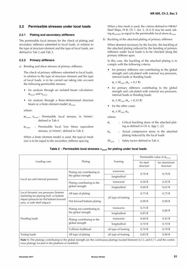
NR 600, Ch 2, Sec 3
2.2 Permissible stresses under local loads
2.2.1 Plating and secondary stiffeners
The permissible local stresses for the check of plating andsecondary stiffeners submitted to local loads, in relation tothe type of structure element and the type of local loads, aredefined in Tab 2 and Tab 3.
2.2.2 Primary stiffeners
a) Bending and shear stresses of primary stiffeners
The check of primary stiffeners submitted to local loads,in relation to the type of structure element and the typeof local loads, is to be carried out taking into accountthe following permissible stresses:
• for analysis through an isolated beam calculation:σlocam and τlocam
• for analysis through a three-dimensional structurebeam or a finite element model: σvmam
where:
σlocam , τlocam : Permissible local stresses, in N/mm2,defined in Tab 4
σvmam : Permissible local Von Mises equivalentstresses, in N/mm2, defined in Tab 4.
When a finite element model is used, the typical meshsize is to be equal to the secondary stiffener spacing.
When a fine mesh is used, the criteria defined in NR467Steel Ships, Pt B, Ch 7, Sec 3, [4.4.3] may be used, tak-ing σMASTER as equal to the permissible local stress σvmam.
b) Buckling of the attached plating of primary stiffeners
When deemed necessary by the Society, the buckling ofthe attached plating induced by the bending of primarystiffeners under local loads is to be checked along theprimary stiffener span.
In this case, the buckling of the attached plating is tocomply with the following criteria:
• for primary stiffeners not contributing to the globalstrength and calculated with external sea pressures,internal loads or flooding loads:
σc ≥ SFbuck (σac + 0,1 R)
• for primary stiffeners contributing to the globalstrength and calculated with external sea pressures,internal loads or flooding loads:
σc ≥ SFbuck (σac + 0,35 R)
• for the other cases:
σc ≥ SFbuck σac
where:
σc : Critical buckling stress of the attached plat-ing as defined in Ch 4, App 1, [2]
σac : Actual compressive stress in the attachedplating induced by the local loads
SFbuck : Safety factor defined in Tab 4.
Table 2 : Permissible local stresses σlocam for plating under local loads
Loading case Plating Framing
Permissible value of σlocam
for steel structure
for aluminium structure
Local sea and internal pressures
Plating not contributing to the global strength
transverse0,70 R 0,70 R
longitudinal
Plating contributing to the global strength
transverse 0,50 R 0,45 R
longitudinal 0,60 R 0,65 R
Local dynamic sea pressures (bottom slamming for planing hull, or bottom impact pressure for flat bottom forward area, or side shell impact)
All type of plating
all type of framing
0,75 R 0,75 R
Flat forward bottom plating 0,90 R 0,90 R
Flooding loads
Plating not contributing to the global strength
transverse 0,75 R0,80 R
longitudinal 0,85 R
Plating contributing to the global strength
transverse 0,60 R 0,45 R
longitudinal 0,70 R 0,70 R
Collision bulkhead all type of framing 0,70 R 0,70 R
Testing loads All type of plating all type of framing 0,85 R 0,90 R
Note 1: The platings contributing to the global strength are the continuous platings located between 0,3 L and 0,7 L and the contin-uous platings located in the platform of multihull.
December 2017 Bureau Veritas 51
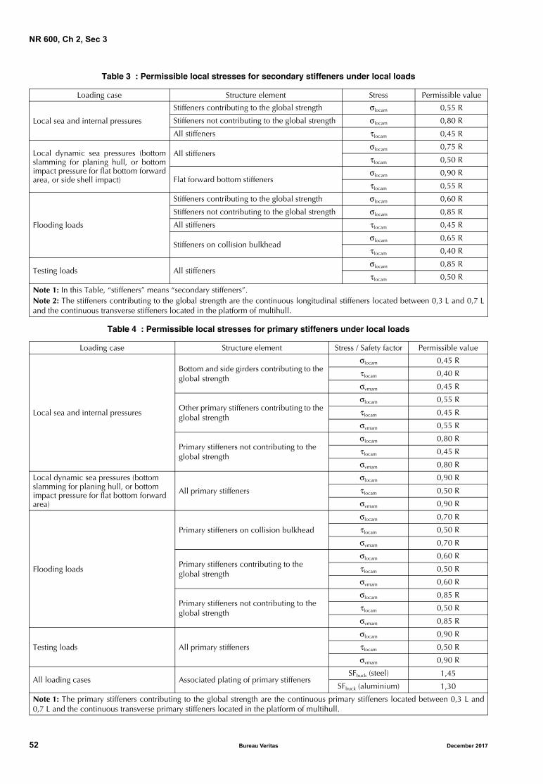
NR 600, Ch 2, Sec 3
Table 3 : Permissible local stresses for secondary stiffeners under local loads
Table 4 : Permissible local stresses for primary stiffeners under local loads
Loading case Structure element Stress Permissible value
Local sea and internal pressures
Stiffeners contributing to the global strength σlocam 0,55 R
Stiffeners not contributing to the global strength σlocam 0,80 R
All stiffeners τlocam 0,45 R
Local dynamic sea pressures (bottomslamming for planing hull, or bottomimpact pressure for flat bottom forwardarea, or side shell impact)
All stiffenersσlocam 0,75 R
τlocam 0,50 R
Flat forward bottom stiffenersσlocam 0,90 R
τlocam 0,55 R
Flooding loads
Stiffeners contributing to the global strength σlocam 0,60 R
Stiffeners not contributing to the global strength σlocam 0,85 R
All stiffeners τlocam 0,45 R
Stiffeners on collision bulkheadσlocam 0,65 R
τlocam 0,40 R
Testing loads All stiffenersσlocam 0,85 R
τlocam 0,50 R
Note 1: In this Table, “stiffeners” means “secondary stiffeners”.Note 2: The stiffeners contributing to the global strength are the continuous longitudinal stiffeners located between 0,3 L and 0,7 Land the continuous transverse stiffeners located in the platform of multihull.
Loading case Structure element Stress / Safety factor Permissible value
Local sea and internal pressures
Bottom and side girders contributing to the global strength
σlocam 0,45 R
τlocam 0,40 R
σvmam 0,45 R
Other primary stiffeners contributing to the global strength
σlocam 0,55 R
τlocam 0,45 R
σvmam 0,55 R
Primary stiffeners not contributing to the global strength
σlocam 0,80 R
τlocam 0,45 R
σvmam 0,80 R
Local dynamic sea pressures (bottom slamming for planing hull, or bottom impact pressure for flat bottom forward area)
All primary stiffeners
σlocam 0,90 R
τlocam 0,50 R
σvmam 0,90 R
Flooding loads
Primary stiffeners on collision bulkhead
σlocam 0,70 R
τlocam 0,50 R
σvmam 0,70 R
Primary stiffeners contributing to the global strength
σlocam 0,60 R
τlocam 0,50 R
σvmam 0,60 R
Primary stiffeners not contributing to the global strength
σlocam 0,85 R
τlocam 0,50 R
σvmam 0,85 R
Testing loads All primary stiffeners
σlocam 0,90 R
τlocam 0,50 R
σvmam 0,90 R
All loading cases Associated plating of primary stiffenersSFbuck (steel) 1,45
SFbuck (aluminium) 1,30
Note 1: The primary stiffeners contributing to the global strength are the continuous primary stiffeners located between 0,3 L and0,7 L and the continuous transverse primary stiffeners located in the platform of multihull.
52 Bureau Veritas December 2017
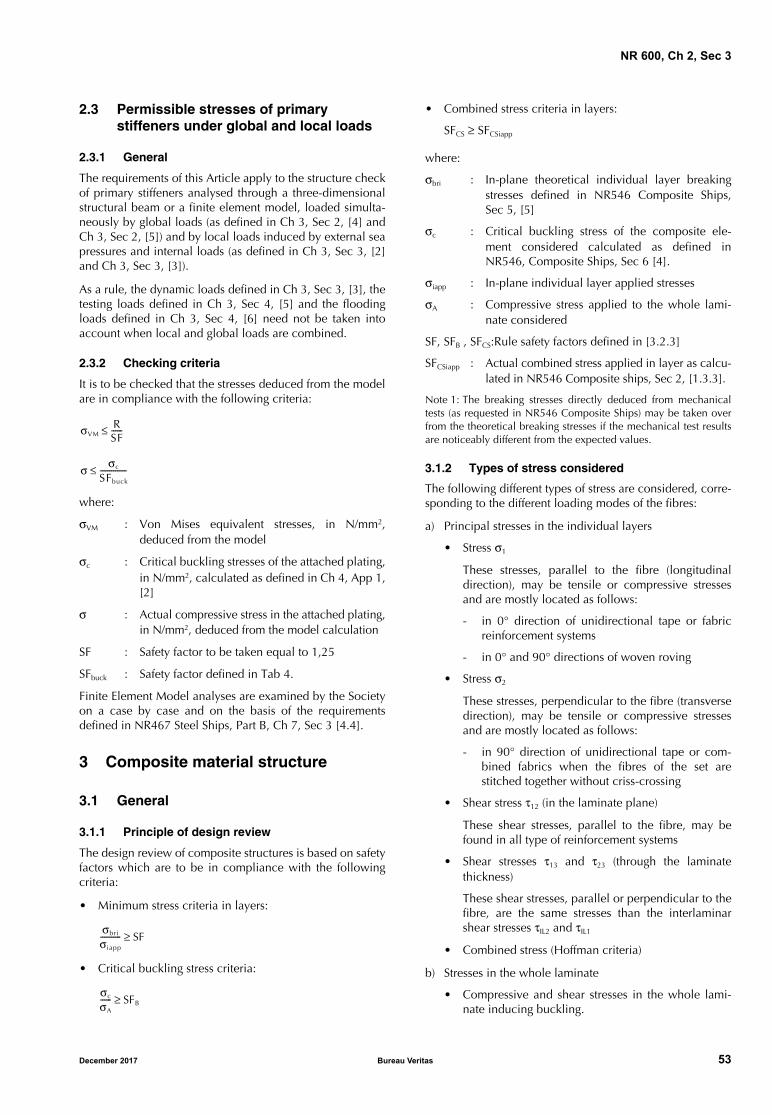
NR 600, Ch 2, Sec 3
2.3 Permissible stresses of primary stiffeners under global and local loads
2.3.1 General
The requirements of this Article apply to the structure checkof primary stiffeners analysed through a three-dimensionalstructural beam or a finite element model, loaded simulta-neously by global loads (as defined in Ch 3, Sec 2, [4] andCh 3, Sec 2, [5]) and by local loads induced by external seapressures and internal loads (as defined in Ch 3, Sec 3, [2]and Ch 3, Sec 3, [3]).
As a rule, the dynamic loads defined in Ch 3, Sec 3, [3], thetesting loads defined in Ch 3, Sec 4, [5] and the floodingloads defined in Ch 3, Sec 4, [6] need not be taken intoaccount when local and global loads are combined.
2.3.2 Checking criteria
It is to be checked that the stresses deduced from the modelare in compliance with the following criteria:
where:
σVM : Von Mises equivalent stresses, in N/mm2,deduced from the model
σc : Critical buckling stresses of the attached plating,in N/mm2, calculated as defined in Ch 4, App 1,[2]
σ : Actual compressive stress in the attached plating,in N/mm2, deduced from the model calculation
SF : Safety factor to be taken equal to 1,25
SFbuck : Safety factor defined in Tab 4.
Finite Element Model analyses are examined by the Societyon a case by case and on the basis of the requirementsdefined in NR467 Steel Ships, Part B, Ch 7, Sec 3 [4.4].
3 Composite material structure
3.1 General
3.1.1 Principle of design review
The design review of composite structures is based on safetyfactors which are to be in compliance with the followingcriteria:
• Minimum stress criteria in layers:
• Critical buckling stress criteria:
• Combined stress criteria in layers:
SFCS ≥ SFCSiapp
where:
σbri : In-plane theoretical individual layer breakingstresses defined in NR546 Composite Ships,Sec 5, [5]
σc : Critical buckling stress of the composite ele-ment considered calculated as defined inNR546, Composite Ships, Sec 6 [4].
σiapp : In-plane individual layer applied stresses
σA : Compressive stress applied to the whole lami-nate considered
SF, SFB , SFCS:Rule safety factors defined in [3.2.3]
SFCSiapp : Actual combined stress applied in layer as calcu-lated in NR546 Composite ships, Sec 2, [1.3.3].
Note 1: The breaking stresses directly deduced from mechanicaltests (as requested in NR546 Composite Ships) may be taken overfrom the theoretical breaking stresses if the mechanical test resultsare noticeably different from the expected values.
3.1.2 Types of stress considered
The following different types of stress are considered, corre-sponding to the different loading modes of the fibres:
a) Principal stresses in the individual layers
• Stress σ1
These stresses, parallel to the fibre (longitudinaldirection), may be tensile or compressive stressesand are mostly located as follows:
- in 0° direction of unidirectional tape or fabricreinforcement systems
- in 0° and 90° directions of woven roving
• Stress σ2
These stresses, perpendicular to the fibre (transversedirection), may be tensile or compressive stressesand are mostly located as follows:
- in 90° direction of unidirectional tape or com-bined fabrics when the fibres of the set arestitched together without criss-crossing
• Shear stress τ12 (in the laminate plane)
These shear stresses, parallel to the fibre, may befound in all type of reinforcement systems
• Shear stresses τ13 and τ23 (through the laminatethickness)
These shear stresses, parallel or perpendicular to thefibre, are the same stresses than the interlaminarshear stresses τIL2 and τIL1
• Combined stress (Hoffman criteria)
b) Stresses in the whole laminate
• Compressive and shear stresses in the whole lami-nate inducing buckling.
σVMRSF------≤
σ σc
SFbuck
--------------≤
σbri
σiapp
----------- SF≥
σc
σA
------ SFB≥
December 2017 Bureau Veritas 53
NR 600, Ch 2, Sec 3
3.1.3 Theoretical breaking criteriaThree theoretical breaking criteria are used in the presentRules:
a) the maximum stress criteria leading to the breaking ofthe component resin/fibre of one elementary layer of thefull lay-up laminate
b) the Hoffman combined stress criteria with the hypothe-sis of in-plane stresses in each layer
c) the critical buckling stress criteria applied to the laminate.The theoretical breaking criteria defined in items a) and b)are to be checked for each individual layer.
The theoretical breaking criteria defined in item c) is to bechecked for the global laminate.
3.1.4 First ply failureIt is considered that the full lay-up laminate breakingstrength is reached as soon as the lowest breaking strengthof any elementary layer is reached. This is referred to as“first ply failure”.
3.2 Rule safety factors
3.2.1 Generala) General consideration:
The rule safety factors to be considered for the compos-ite structure check are defined in [3.2.3], according tothe partial safety factors defined in [3.2.2].
b) Additional considerations:Rule safety factors other than those defined in [3.2.3]may be accepted for one elementary layer when the fulllay-up laminate exhibits a sufficient safety marginbetween the theoretical breaking stress of this elemen-tary layer and the theoretical breaking stress of the otherelementary layers.Finite Element Model analyses are examined on a caseby case basis by the Society. As a rule, when the struc-ture is checked with a Finite Element Model, the rulesafety factors defined in [3.2.3] and [3.2.4] may bereduced by ten per cent.
3.2.2 Partial safety factorsAs a general rule, the minimum partial safety factors consid-ered are to be as follows:
a) Ageing effect factor CV
CV takes into account the ageing effect of the compos-ites and is generally taken equal to:
CV = 1,2 for monolithic laminates (or for face-skinslaminates of sandwich)CV = 1,1 for sandwich core materials
b) Fabrication process factor CF
CF takes into account the fabrication process and thereproducibility of the fabrication and is generally takenequal to:
CF = 1,10 in case of a prepreg process
CF = 1,15 in case of infusion and vacuum process
CF = 1,25 in case of a hand lay-up process
CF = 1,00 for the core materials of sandwich com-posite
c) Type of load factor Ci
Ci takes into account the type of loads and is generallytaken equal to:
Ci = 1,0 for local external sea pressures and internalpressures or concentrated forces
Ci = 0,8 for dynamic sea pressures (slamming loadson bottom and impact on flat bottom on forwardarea) and for test pressures and flooding loads
Ci = 0,6 for impact pressure on side shell and onplatform bottom of multihull
d) Type of stress factor CR
CR takes into account the type of stress in the fibres ofthe reinforcement fabrics and the cores and is generallytaken equal to:
1) For fibres of the reinforcement fabrics
• for tensile or compressive stress parallel to thecontinuous fibre of the reinforcement fabric:
CR = 2,1 for unidirectional tape, bi-bias,three-unidirectional fabric
CR = 2,4 for woven roving
• for tensile or compressive stress perpendicular tothe continuous fibre of the reinforcement fabric:
CR = 1,0 for unidirectional tape, bi-bias,three-unidirectional fabric
• for shear stress parallel to the fibre in the ele-mentary layer and for interlaminar shear stress inthe laminate:
CR = 1,6 for unidirectional tape, bi-bias,three-unidirectional fabric
CR = 1,8 for woven roving
• for mat layer:
CR = 2,0 for tensile or compressive stress inthe layer
CR = 2,2 for shear stress in the layer and forinterlaminar shear stress
2) For core materials
• for tensile or compressive stress for cores:
- in the general case:
CR = 2,1 for tensile or compressive stress
- for balsa:
CR = 2,1 for tensile or compressive stress par-allel to the wood grain
CR = 1,2 for tensile or compressive stress per-pendicular to the wood grain
• for shear stress, whatever the type of core material:
CR = 2,5
3) For wood materials for strip planking
CR = 2,4 for tensile or compressive stress parallelto the continuous fibre of the strip planking
CR = 1,2 for tensile or compressive stress perpen-dicular to the continuous fibre of the strip plank-ing
CR = 2,2 for shear stress parallel to the fibre andfor interlaminar shear stress in the strip planking.
54 Bureau Veritas December 2017
NR 600, Ch 2, Sec 3
3.2.3 Rule safety factors
The rule safety factors SF, SFCS and SFB to be considered forthe composite structure check are defined according to thetype of hull structure calculation, as follows:
a) For structure checked under local loads or under globalhull girder loads
1) Minimum stress criterion in layers:
SF = CV CF CR Ci
with:
CV : Partial safety factor:
• CV to be taken as defined in [3.2.2]item a) for the check of the structureunder local loads
• CV = 1,1 for the check of the globalhull girder structure when examinedas required in Ch 4, Sec 2, [1.1.3]
CR : Partial safety factor defined in [3.2.2]
2) Combined stress criterion in layers:
SFCS = CCS CV CF Ci
with:
CCS : Partial safety factor, to be taken equal to:
• CCS = 1,7 for unidirectional tape, bi-bias, three-unidirectional fabric
• CCS = 2,1 for the other types of layer
CV : Partial safety factor defined in [3.2.2]
3) Critical buckling stress criterion:
SFB = CBuck CV CF Ci
with:
CBuck , CV : Partial safety factors, to be taken equal to:
• CBuck = 1,45 and CV as defined in[3.2.2] item a) for the check of thestructure under local loads
• CBuck = 1,35 and CV = 1,0 for thecheck of the global hull girder struc-ture when examined as required inCh 4, Sec 2, [1.1.3]
where:
CF , Ci : Partial safety factors defined in [3.2.2].
Note 1: For planing hull, when the global stress is calcu-lated with the minimum bending momentsdefined in Ch 3, Sec 2, [6.1], Ci may be takenequal to 0,8 to determine SF, SFCS and SFB.
b) For structure checked under local loads combined withglobal loads
When the structure check is carried out through a three-dimensional structural beam or a finite element modelloaded simultaneously by global loads (as defined in Ch3, Sec 2, [4] and Ch 3, Sec 2, [5]) and by local loadsinduced by external sea pressure and internal loads (as
defined in Ch 3, Sec 3 and Ch 3, Sec 4), the rule safetyfactors are to be taken as follows:
1) Combined stress criterion in layers:
• for unidirectional tape, bi-bias, three-unidirec-tional fabric:
SFCS = 1,4 CV CF Ci
• for the other types of layer:
SFCS = 1,8 CV CF Ci
with:
SFCS : Rule safety factor calculated according toNR546 Composite Ships, Sec 2, [1.3.3]
2) Critical buckling stress criterion:
SFB = 1,45 CV CF Ci
where:
CV , CF , Ci : Partial safety factors defined in [3.2.2].
As a rule, the dynamic loads defined in Ch 3, Sec 3, [3],the testing loads defined in Ch 3, Sec 4, [5] and theflooding loads defined in Ch 3, Sec 4, [6] need not betaken into account when local and global loads arecombined.
3.2.4 Rule safety factor for structural adhesive joints
The structural adhesive characteristics are to be as definedin NR546 Composite Ships.
As a general rule, the rule safety factor SF considered in thepresent Rules and applicable to the maximum shear stressin adhesive joints is to be calculated as follows:
SF = 2,4 CF
where:
CF : Factor taking into account the gluing processand generally taken as follows:
• CF = 1,4 in case of a vacuum process withrising curing temperature
• CF = 1,5 in case of vacuum process
• CF = 1,7 in the other cases.
4 Plywood structure
4.1 General
4.1.1 Principle of design review
As a rule, plywood structures are checked according to anhomogeneous material approach, or by a “ply by ply”approach as defined in NR546 Composite Ships.
4.2 Rule safety factors
4.2.1 Homogeneous material approach
As a general rule, the rule safety factor SF to be taken intoaccount in the global formula used to determine the platingthickness or the permissible stress in stiffeners is to be equalto, or greater than, 4,0.
December 2017 Bureau Veritas 55
NR 600, Ch 2, Sec 3
4.2.2 Ply by ply approach
As a general rule, the rule safety factor SF applicable to themaximum stress in each layer of the plywood is to be calcu-lated as follows:
a) Minimum stress criterion in layers
SF = CR Ci CV
with:
CR : Factor taking into account the type of stressin the grain of the plywood layer. Generally:
• CR = 3,7 for a tensile or compressivestress parallel to the grain of the ply con-sidered
• CR = 2,4 for tensile or compressive stressperpendicular to the grain of the plyconsidered
• CR = 2,9 for a shear stress parallel to thegrain of the ply considered
Ci : Factor taking into account the type of loads.Generally:
• Ci = 1,0 for local external sea pressuresand internal pressures or concentratedforces
• Ci = 0,8 for dynamic sea pressures (slam-ming loads on bottom, impact on flatbottom in forward area), and for testpressures and flooding loads
• Ci = 0,6 for impact pressure on side shelland on platform bottom of multihull
CV : Factor taking into account the ageing effectof the plywood, to be taken at least equal to1,2
b) Critical buckling stress criterionAs a general rule, the rule safety factor SFB applicable tothe critical buckling stress criterion is to be calculated asfollows: SFB = CBuck CV Ci
with:CBuck , CV : Partial safety factors, to be taken equal to:
• CBuck =1,45 and CV = 1,2 for the checkof the structure under local loads
• CBuck = 1,35 and CV = 1,0 for the checkof the global hull girder structure whenexamined as required in Ch 4, Sec 2,[1.1.3].
Ci : Partial safety factor defined in [3.2.2].Note 1: For planing hull, when the global stress is calculated withthe minimum bending moments defined in Ch 3, Sec 2, [6.1], Ci
may be taken equal to 0,8.
56 Bureau Veritas December 2017

NR 600
Chapter 3
DESIGN LOADS
SECTION 1 GENERAL
SECTION 2 HULL GIRDER LOADS
SECTION 3 LOCAL EXTERNAL PRESSURES
SECTION 4 LOCAL INTERNAL PRESSURE AND FORCES
December 2017 Bureau Veritas 57

58 Bureau Veritas December 2017
NR 600, Ch 3, Sec 1
SECTION 1 GENERAL
1 Application
1.1 General
1.1.1 As a general rule, the wave loads and the shipmotions and accelerations defined in the present Chapterare assumed to be periodic and can be reached with aprobability level of 10−5.
1.1.2 As an alternative to the present Chapter, the Societymay accept the values of ship motions and accelerationsderived from direct calculations or obtained from modeltests, when justified on the basis of the ship characteristicsand intended service. In general, the values of ship motionsand accelerations to be determined are those which can bereached with the probability level defined in [1.1.1]. In anycase, the model tests or the calculations, including theassumed sea scatter diagrams and spectra, are to be submit-ted to the Society for approval.
1.1.3 Requirements applicable to specific ship types
Additional specific loads, as defined in NR467 Steel Ships,Part D or Part E, may be considered in addition to thosedefined in the present Chapter, in relation to the servicenotation and the additional service features assigned to theship (see Ch 6, Sec 1).
2 Definition
2.1 Hull girder loads
2.1.1 Hull girder loads (still water loads, wave loads anddynamic loads) are forces and moments which result fromthe effects of local loads acting on the ship as a whole andconsidered as a beam.
These loads are considered for the hull girder strength checkand are defined in Sec 2.
2.2 Local external pressures
2.2.1 The local external pressures are local pressures (stillwater, wave and dynamic) applied to the individual localstructure (plating, secondary stiffeners and primary support-ing members).
These local external pressures are considered for the localstructure check and are defined in Sec 3.
2.3 Local internal pressures and forces
2.3.1 The local internal pressures and forces are local pres-sures (still water and inertial pressure) applied to the localinternal structure (plating, secondary stiffeners and primarysupporting structure) and include liquid loads, dry cargoes(bulk, uniform or unit), wheeled loads and accommodationdeck loads.
Flooding pressures induced by damage and testing pres-sures are also considered as local internal pressures.
These local internal pressures and forces are considered forthe local internal structure check and are defined in Sec 4.
3 Local pressure application
3.1 Application
3.1.1 The local pressures to be used in the scantling checksof plating, secondary stiffeners and primary supportingmembers are the following ones:
a) For an element of the outer shell: the local external pres-sures (still water and wave) considered as acting alone,without any counteraction from the ship internal loadsin ship full load condition.
However, for an element of the outer shell adjacent to aliquid compartment, the local load to be used in thescantling checks of plating, secondary stiffeners and pri-mary supporting members of the shell is to be takenequal to the greater value between:
• the local load as defined just above, and
• for cargo ship:
p = pint − 10 (TB − h1 − z)
with:
TB − h1 − z ≥ 0
• for non cargo ship:
p = pint − 10 (T − h1 − z)
with:
T − h1 − z ≥ 0
where:
pint : Local internal pressure, in kN/m2, as definedin Sec 4
T : Draught, in m.
TB : Draught in ballast condition, in m, meas-ured from the base line
When TB is unknown, TB may be takenequal to 0,03 LWL
December 2017 Bureau Veritas 59
NR 600, Ch 3, Sec 1
h1 : Ship relative motion in the considered area,in m, as defined in Sec 3, [2.1]
z : Load point calculation as defined in [4].
b) For an element inside the hull: the local internal pres-sures, the adjacent compartments being consideredindividually loaded, without any counteraction
c) For testing conditions: the internal testing pressures con-sidered as acting alone, without external load counter-action
d) For flooding conditions: the internal flooding pressureson internal watertight elements considered without anycounteraction on the internal watertight element consid-ered.
3.1.2 Ship draughtThe ship draught to be considered for the combination ofthe local loads is to correspond to:• the full load condition: when one or more cargo com-
partments (oil tank, dry cargo hold, vehicle spaces) areconsidered as being loaded and the ballast tanks empty
• the light ballast condition: when one or more ballasttanks are considered as loaded and the cargo compart-ments empty (in the absence of more precise informa-tion, the ship’s draught in light ballast condition, in m,may be taken equal to 0,03 LWL).
4 Local load point location
4.1 General case for structures made of steel or aluminium alloys
4.1.1 Still water and wave loadsUnless otherwise specified, the local loads are to be calcu-lated: • for plate panels: at the lower edge of the plate panels• for horizontal stiffeners: at mid-span of the stiffeners• for vertical stiffeners: at the lower and upper vertical
points of the stiffeners.
4.1.2 Dynamic loads
Unless otherwise specified, the dynamic loads are to be cal-culated:
• for plate panels: at mid-edge of the plate panels
• for longitudinal and transverse stiffeners: at mid-span ofthe stiffeners.
4.2 General case for structures made of composite materials
4.2.1 Still water and wave loads
Unless otherwise specified, the local loads are to be calcu-lated:
• for plate panels:
- at the lower edge of the plate panels for monolithic,and
- at the middle of the plate panels for sandwich
• for horizontal stiffeners: at mid-span of the stiffeners
• for vertical stiffeners: at the lower and upper verticalpoints of the stiffeners.
4.2.2 Dynamic loads
Unless otherwise specified, the dynamic loads are to be cal-culated:
• for plate panels: at mid-edge of the plate panels
• for longitudinal and transverse stiffeners: at mid-span ofthe stiffeners.
4.3 Superstructures and deckhouses
4.3.1 For superstructures and deckhouses, the lateral pres-sures are to be calculated, for all type of materials:
• for plating: at mid-height of the bulkhead
• for horizontal and vertical stiffeners: at mid-span of thestiffeners.
60 Bureau Veritas December 2017
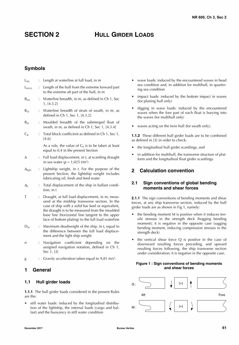
NR 600, Ch 3, Sec 2
SECTION 2 HULL GIRDER LOADS
Symbols
LWL : Length at waterline at full load, in m
LHULL : Length of the hull from the extreme forward partto the extreme aft part of the hull, in m
BWL : Waterline breadth, in m, as defined in Ch 1, Sec1, [4.3.2]
BST : Waterline breadth of struts of swath, in m, asdefined in Ch 1, Sec 1, [4.3.2]
BSF : Moulded breadth of the submerged float ofswath, in m, as defined in Ch 1, Sec 1, [4.3.4]
CB : Total block coefficient as defined in Ch 1, Sec 1,[4.6]
As a rule, the value of CB is to be taken at leastequal to 0,4 in the present Section
Δ : Full load displacement, in t, at scantling draughtin sea water (ρ = 1,025 t/m3)
Δlight : Lightship weight, in t. For the purpose of thepresent Section, the lightship weight includeslubricating oil, fresh and feed water
Δb : Total displacement of the ship in ballast condi-tion, in t
T : Draught, at full load displacement, in m, meas-ured at the midship transverse section. In thecase of ship with a solid bar keel or equivalent,the draught is to be measured from the mouldedbase line (horizontal line tangent to the upperface of bottom plating) to the full load waterline
DW : Maximum deadweight of the ship, in t, equal tothe difference between the full load displace-ment and the light ship weight
n : Navigation coefficient depending on theassigned navigation notation, defined in Ch 1,Sec 1, [3]
g : Gravity acceleration taken equal to 9,81 m/s2.
1 General
1.1 Hull girder loads
1.1.1 The hull girder loads considered in the present Rulesare the:
• still water loads: induced by the longitudinal distribu-tion of the lightship, the internal loads (cargo and bal-last) and the buoyancy in still water condition
• wave loads: induced by the encountered waves in headsea condition and, in addition for multihull, in quarter-ing sea condition
• impact loads: induced by the bottom impact in waves(for planing hull only)
• digging in wave loads: induced by the encounteredwaves when the fore part of each float is burying intothe waves (for multihull only)
• waves acting on the twin hull (for swath only).
1.1.2 These different hull girder loads are to be combinedas defined in [3] in order to check:
• the longitudinal hull girder scantlings, and
• in addition for multihull, the transverse structure of plat-form and the longitudinal float girder scantlings.
2 Calculation convention
2.1 Sign conventions of global bending moments and shear forces
2.1.1 The sign conventions of bending moments and shearforces, at any ship transverse section, induced by the hullgirder loads are as shown in Fig 1, namely:
• the bending moment M is positive when it induces ten-sile stresses in the strength deck (hogging bendingmoment); it is negative in the opposite case (saggingbending moment, inducing compression stresses in thestrength deck)
• the vertical shear force Q is positive in the case ofdownward resulting forces preceding, and upwardresulting forces following, the ship transverse sectionunder consideration; it is negative in the opposite case.
Figure 1 : Sign conventions of bending momentsand shear forces
Q :
M :
Aft Fore
(+)
(+)
December 2017 Bureau Veritas 61
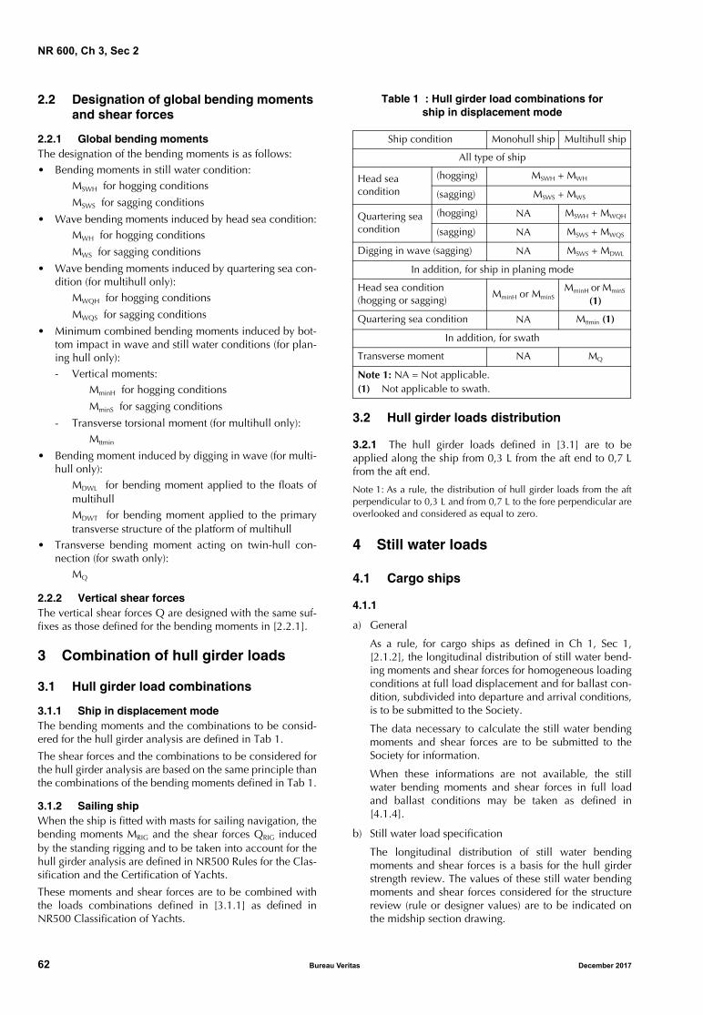
NR 600, Ch 3, Sec 2
2.2 Designation of global bending moments and shear forces
2.2.1 Global bending momentsThe designation of the bending moments is as follows:• Bending moments in still water condition:
MSWH for hogging conditions
MSWS for sagging conditions
• Wave bending moments induced by head sea condition:MWH for hogging conditions
MWS for sagging conditions
• Wave bending moments induced by quartering sea con-dition (for multihull only):
MWQH for hogging conditions
MWQS for sagging conditions
• Minimum combined bending moments induced by bot-tom impact in wave and still water conditions (for plan-ing hull only):- Vertical moments:
MminH for hogging conditions
MminS for sagging conditions
- Transverse torsional moment (for multihull only):Mttmin
• Bending moment induced by digging in wave (for multi-hull only):
MDWL for bending moment applied to the floats ofmultihullMDWT for bending moment applied to the primarytransverse structure of the platform of multihull
• Transverse bending moment acting on twin-hull con-nection (for swath only):
MQ
2.2.2 Vertical shear forcesThe vertical shear forces Q are designed with the same suf-fixes as those defined for the bending moments in [2.2.1].
3 Combination of hull girder loads
3.1 Hull girder load combinations
3.1.1 Ship in displacement modeThe bending moments and the combinations to be consid-ered for the hull girder analysis are defined in Tab 1.
The shear forces and the combinations to be considered forthe hull girder analysis are based on the same principle thanthe combinations of the bending moments defined in Tab 1.
3.1.2 Sailing shipWhen the ship is fitted with masts for sailing navigation, thebending moments MRIG and the shear forces QRIG inducedby the standing rigging and to be taken into account for thehull girder analysis are defined in NR500 Rules for the Clas-sification and the Certification of Yachts.
These moments and shear forces are to be combined withthe loads combinations defined in [3.1.1] as defined inNR500 Classification of Yachts.
Table 1 : Hull girder load combinations for ship in displacement mode
3.2 Hull girder loads distribution
3.2.1 The hull girder loads defined in [3.1] are to beapplied along the ship from 0,3 L from the aft end to 0,7 Lfrom the aft end.
Note 1: As a rule, the distribution of hull girder loads from the aftperpendicular to 0,3 L and from 0,7 L to the fore perpendicular areoverlooked and considered as equal to zero.
4 Still water loads
4.1 Cargo ships
4.1.1
a) General
As a rule, for cargo ships as defined in Ch 1, Sec 1,[2.1.2], the longitudinal distribution of still water bend-ing moments and shear forces for homogeneous loadingconditions at full load displacement and for ballast con-dition, subdivided into departure and arrival conditions,is to be submitted to the Society.
The data necessary to calculate the still water bendingmoments and shear forces are to be submitted to theSociety for information.
When these informations are not available, the stillwater bending moments and shear forces in full loadand ballast conditions may be taken as defined in[4.1.4].
b) Still water load specification
The longitudinal distribution of still water bendingmoments and shear forces is a basis for the hull girderstrength review. The values of these still water bendingmoments and shear forces considered for the structurereview (rule or designer values) are to be indicated onthe midship section drawing.
Ship condition Monohull ship Multihull ship
All type of ship
Head sea condition
(hogging) MSWH + MWH
(sagging) MSWS + MWS
Quartering sea condition
(hogging) NA MSWH + MWQH
(sagging) NA MSWS + MWQS
Digging in wave (sagging) NA MSWS + MDWL
In addition, for ship in planing mode
Head sea condition (hogging or sagging)
MminH or MminSMminH or MminS
(1)
Quartering sea condition NA Mttmin (1)
In addition, for swath
Transverse moment NA MQ
Note 1: NA = Not applicable.(1) Not applicable to swath.
62 Bureau Veritas December 2017
NR 600, Ch 3, Sec 2
4.1.2 For ships having alternate light and heavy cargo load-ing conditions, see Ch 1, Sec 1, [1.2.2].
4.1.3 Particular types of shipSupply vessels, barges, fishing vessels, and all types of shipnot considered as cargo ships as defined in Ch 1, Sec 1,[2.1.2] but liable to carry loading or equivalent loads, maybe however examined, for a hull girder load in still waterpoint of view, with the present requirements for cargo ships,when deemed necessary by the Society.
4.1.4 Still water bending moments and shear forces
a) Hogging conditions
In hogging conditions, the maximum bending momentMSWH , in kN⋅m, and the maximum shear force QSWH , inkN, may be calculated, in ballast condition, as follows:
MSWH = 5 [0,28 LWL Δlight + Σ (xi DWloci) − 0,198 LWL Δb]
where:
DWloci : Weight, in t, of the ballasts considered
xi : Distance, in m, between the midship per-pendicular and the centre of gravity of theconsidered ballasts (the sign of xi is alwaysto be considered positive)
Note 1: When the value of MSWH is negative, MSWH is to be consid-ered as a minimum sagging moment (in this case, the ship isalways in sagging condition in still water).
b) Sagging conditions
In sagging conditions, the maximum bending momentMSWS , in kN⋅m, and the maximum shear force QSWS , inkN, may be calculated, in full load condition (for homo-geneous loading case only), as follows:
MSWS = 5 [0,28 LWL Δlight + X DW − 0,225 LWL Δ]
where:
X : Distance, in m, taken equal to:
X1 , X2 : Distances, in m, between the aft perpendic-ular of the ship and, respectively, the aftboundary and the fore boundary of thecargo holds.
Note 2: When the value of MSWS is positive, MSWS is to be consid-ered as a minimum hogging moment (in this case, the ship isalways in hogging condition in still water).
Note 3: These formulae are to be used only for ships having theirmachinery space and superstructure located in the ship aft part.
c) Hogging and sagging conditions for catamaran andswath considered as cargo ships
For catamaran and swath considered as cargo, the max-imum values of bending moments and shear forces inhogging and sagging conditions calculated according toitem a) and item b) are to be reduced by 50%.
4.2 Non cargo ships
4.2.1 Still water bending moments and shear forces
a) Hogging conditions for monohull and catamaran
In hogging conditions, the maximum bending momentMSWH , in kN⋅m, and the maximum shear force QSWH , inkN, may be calculated as follows:
MSWH = 0,8 (0,25 CW LW2 BWL CB)
where:
LW , CW : Wave length and wave parameter, respec-tively, as defined in [5.2.2]
b) Sagging conditions for monohull and catamaran
In sagging conditions, the maximum bending momentMSWS , in kN⋅m, and the maximum shear force QSWS , inkN, may be taken equal to:
MSWS = QSWS = 0
c) Hogging and sagging conditions for swath
In hogging and sagging conditions, the maximum bend-ing moments and the maximum shear forces for swathare to be calculated as defined in item a) and item b),using the breadth BSF instead of BWL in the formulae.
For ships having a superstructure distribution all along theship length or located in the midship area from 0,3 L to 0,7L from the aft end, the maximum bending moments and themaximum shear forces in hogging conditions may bereduced by 40%.
5 Wave loads
5.1 General
5.1.1 Ship in displacement modeWave loads are induced by the encountered waves in headsea condition.
The design encountered waves, considered with a probabil-ity level of 10−5, are represented by an equivalent staticwave defined in [5.2.2].
As an alternative, the Society may accept the values of waveinduced loads derived from direct calculations, when justi-fied on the basis of the ship characteristics and intendedservice. The calculations are to be submitted to the Societyfor approval.
5.1.2 Ship in planing modeIn addition to the calculation to be carried out as defined in[5.1.1], the combined bending moments and shear forcesinduced by impact loads are to be calculated according to[6.1] for planing hull.
As an alternative, the Society may accept the values ofimpact loads derived from direct calculations, when justi-fied on the basis of the ship characteristics and intendedservice. The calculations are to be submitted to the Societyfor approval.
QSWH4MSWH
LWL
-----------------=
QSWS4MSWS
LWL
----------------=
X0 5LWL, X1–( )2 X2 0 5LWL,–( )2+
2 X2 X1–( )----------------------------------------------------------------------------------=
QSWH4MSWH
LWL
-----------------=
December 2017 Bureau Veritas 63

NR 600, Ch 3, Sec 2
5.1.3 Additional wave loads for multihull
Wave loads are induced by the encountered waves in quar-tering sea condition.
The design encountered waves, considered with a probabil-ity level of 10−5, are represented by an equivalent staticwave defined in [5.3.1].
As an alternative, the Society may accept the values of waveinduced loads and impact loads derived from direct calcu-lations, when justified on the basis of the ship characteris-tics and intended service. The calculations are to besubmitted to the Society for approval.
In addition to the moment defined in head sea condition,the torsional moments applied to the platform of multihull(inducing bending moment and shear force in the floats andin the primary transverse cross structure of the platform) areto be calculated according to the following hypotheses:
• For multihull:
- in quartering sea condition: the forward perpendicu-lar of one float and the aftward perpendicular of theother float are on the crest of the wave (see [5.3])
- digging in wave: the fore part of each float buriesinto the wave down to a depth as defined in [6.2.1]
• In addition, for swath:
- wave acting on twin hull (see [6.2.2]).
5.2 Wave loads in head sea condition
5.2.1 Wave loads in head sea condition
The bending moments and shear forces induced by wave inhead sea condition are calculated according to [5.2.3], con-sidering the following hypotheses:
• the forward and aftward perpendiculars of the hull areon the crest (sagging conditions), or
• the forward and aftward perpendiculars of the hull areon the trough (hogging conditions).
The values obtained are to be applied along the ship from0,3 L to 0,7 L from the aft end.
When deemed necessary by the Society, a distribution ofthe bending moments and shear forces as defined in NR467Steel Ships, Ch 5, Sec 2, [3] may be considered.
5.2.2 Wave characteristics for head sea condition
The characteristics of the encountered waves to be consid-ered in head sea condition (equivalent static wave) are asfollows:
• sinusoidal type
• wave length LW , in m, equal to:
LW = 0,5 (LWL + LHULL)
• wave parameter CW , in m, equal to:
CW = 0,625 (118 − 0,36 LW) LW ⋅ 10−3
5.2.3 Wave bending moments and shear forces
a) Hogging conditions for monohull ship
In hogging conditions, the maximum bending momentMWH , in kN⋅m, and the maximum shear force QWH , inkN, along one float in head sea condition, are obtainedfrom the following formulae:
MWH = 0,20 n CW LW2 BWL CB
QWH = 0,65 n CW LW BWL CB
b) Sagging conditions for monohull ship
In sagging conditions, the maximum bending momentMWS , in kN⋅m, and the maximum shear force QWS , inkN, along one float in head sea condition, are obtainedfrom the following formulae:
MWS = − 0,25 n CW LW2 BWL CB
QWS = − 0,75 n CW LW BWL CB
where:
LW , CW : Wave length and wave parameter, respec-tively, as defined in [5.2.2]
BWL : Breadth at waterline, in m, of one float.
c) Hogging and sagging conditions for catamaran
The maximum values of the wave bending moments andshear forces for catamaran are to be calculated asdefined in items a) and b), increased by 10%.
d) Hogging and sagging conditions for swath
The maximum values of the wave bending moments andshear forces for swath are to be calculated as defined initem c), using the breadth BST instead of BWL in the for-mulae.
5.3 Wave loads in quartering sea condition for multihull
5.3.1 Wave characteristics for quartering sea condition
The characteristics of the encountered waves to be consid-ered in quartering sea condition (equivalent static wave) areas follows:
• sinusoidal type
• wave length LWQ , in m, resulting from the quarteringwave position and defined as follows (see Fig 2):
where:
LW : Wave length, in m, as defined in [5.2.2]
BE : Distance, in m, between the float axes (seeFig 2)
• wave parameter CWQ , in m, equal to:
CWQ = 0,625 (118 − 0,36 LWQ) LWQ ⋅ 10−3
LWQ2LWBE
LW2 BE
2+-----------------------=
64 Bureau Veritas December 2017
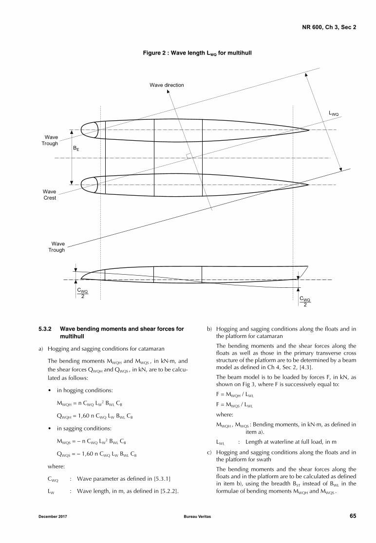
NR 600, Ch 3, Sec 2
Figure 2 : Wave length LWQ for multihull
5.3.2 Wave bending moments and shear forces for multihull
a) Hogging and sagging conditions for catamaran
The bending moments MWQH and MWQS , in kN⋅m, andthe shear forces QWQH and QWQS , in kN, are to be calcu-lated as follows:
• in hogging conditions:
MWQH = n CWQ LW2 BWL CB
QWQH = 1,60 n CWQ LW BWL CB
• in sagging conditions:
MWQS = − n CWQ LW2 BWL CB
QWQS = − 1,60 n CWQ LW BWL CB
where:
CWQ : Wave parameter as defined in [5.3.1]
LW : Wave length, in m, as defined in [5.2.2].
b) Hogging and sagging conditions along the floats and inthe platform for catamaran
The bending moments and the shear forces along thefloats as well as those in the primary transverse crossstructure of the platform are to be determined by a beammodel as defined in Ch 4, Sec 2, [4.3].
The beam model is to be loaded by forces F, in kN, asshown on Fig 3, where F is successively equal to:
F = MWQH / LWL
F = MWQS / LWL
where:
MWQH , MWQS : Bending moments, in kN⋅m, as defined initem a).
LWL : Length at waterline at full load, in m
c) Hogging and sagging conditions along the floats and inthe platform for swath
The bending moments and the shear forces along thefloats and in the platform are to be calculated as definedin item b), using the breadth BST instead of BWL in theformulae of bending moments MWQH and MWQS .
BE
WaveTrough
WaveCrest
WaveTrough
LWQ
CWQ2
Wave direction
CWQ2
December 2017 Bureau Veritas 65
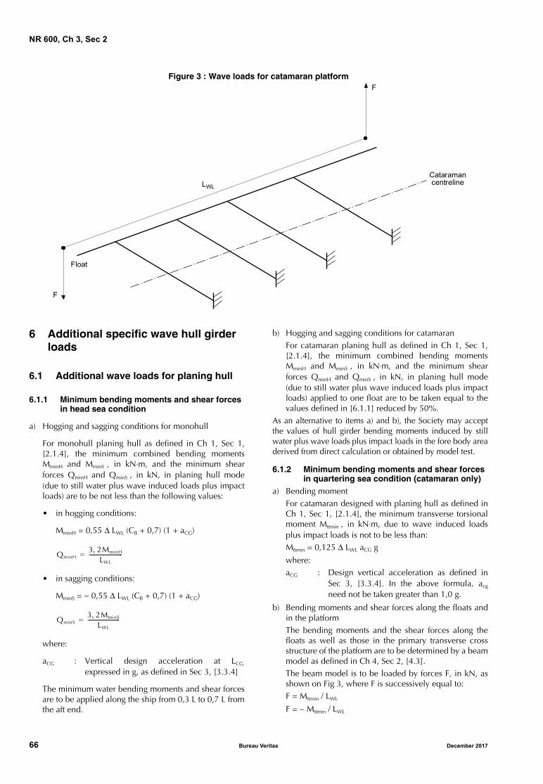
NR 600, Ch 3, Sec 2
Figure 3 : Wave loads for catamaran platform
6 Additional specific wave hull girder loads
6.1 Additional wave loads for planing hull
6.1.1 Minimum bending moments and shear forces in head sea condition
a) Hogging and sagging conditions for monohull
For monohull planing hull as defined in Ch 1, Sec 1,[2.1.4], the minimum combined bending momentsMminH and MminS , in kN⋅m, and the minimum shearforces QminH and QminS , in kN, in planing hull mode(due to still water plus wave induced loads plus impactloads) are to be not less than the following values:
• in hogging conditions:
MminH = 0,55 Δ LWL (CB + 0,7) (1 + aCG)
• in sagging conditions:
MminS = − 0,55 Δ LWL (CB + 0,7) (1 + aCG)
where:
aCG : Vertical design acceleration at LCG,
expressed in g, as defined in Sec 3, [3.3.4]
The minimum water bending moments and shear forcesare to be applied along the ship from 0,3 L to 0,7 L fromthe aft end.
b) Hogging and sagging conditions for catamaranFor catamaran planing hull as defined in Ch 1, Sec 1,[2.1.4], the minimum combined bending momentsMminH and MminS , in kN⋅m, and the minimum shearforces QminH and QminS , in kN, in planing hull mode(due to still water plus wave induced loads plus impactloads) applied to one float are to be taken equal to thevalues defined in [6.1.1] reduced by 50%.
As an alternative to items a) and b), the Society may acceptthe values of hull girder bending moments induced by stillwater plus wave loads plus impact loads in the fore body areaderived from direct calculation or obtained by model test.
6.1.2 Minimum bending moments and shear forces in quartering sea condition (catamaran only)
a) Bending momentFor catamaran designed with planing hull as defined inCh 1, Sec 1, [2.1.4], the minimum transverse torsionalmoment Mttmin , in kN⋅m, due to wave induced loadsplus impact loads is not to be less than:Mttmin = 0,125 Δ LWL aCG g
where:aCG : Design vertical acceleration as defined in
Sec 3, [3.3.4]. In the above formula, acg
need not be taken greater than 1,0 g.
b) Bending moments and shear forces along the floats andin the platformThe bending moments and the shear forces along thefloats as well as those in the primary transverse crossstructure of the platform are to be determined by a beammodel as defined in Ch 4, Sec 2, [4.3].The beam model is to be loaded by forces F, in kN, asshown on Fig 3, where F is successively equal to:F = Mttmin / LWL
F = − Mttmin / LWL
CataramancentrelineLWL
Float
F
F
QminH3 2MminH,
LWL
-------------------------=
QminS3 2MminS,
LWL
------------------------=
66 Bureau Veritas December 2017
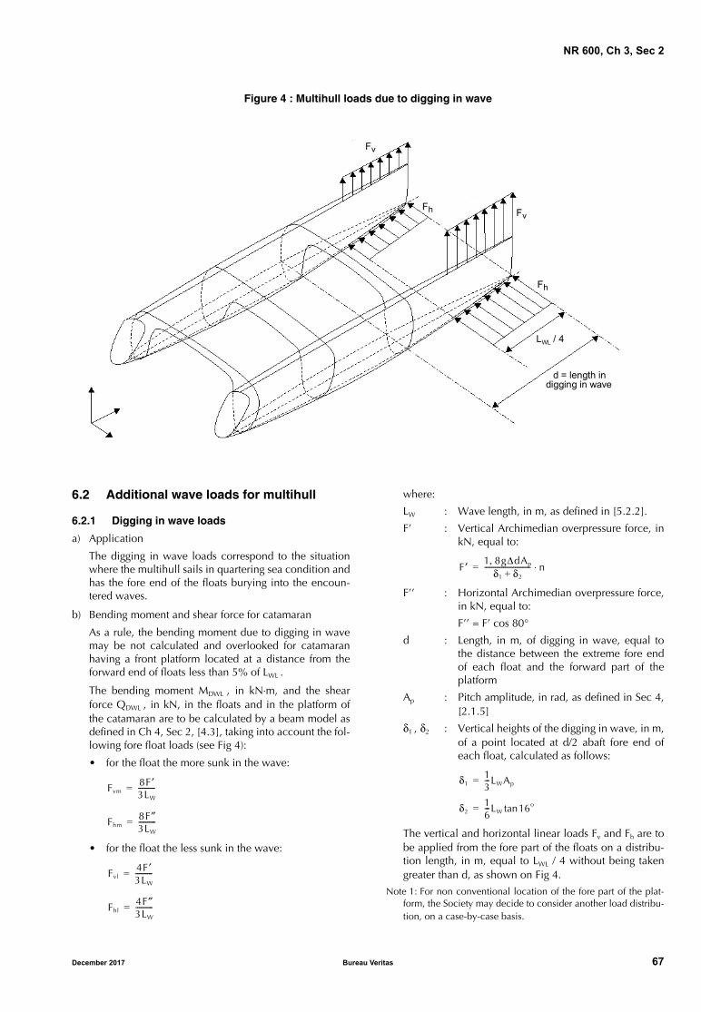
NR 600, Ch 3, Sec 2
Figure 4 : Multihull loads due to digging in wave
6.2 Additional wave loads for multihull
6.2.1 Digging in wave loads
a) Application
The digging in wave loads correspond to the situationwhere the multihull sails in quartering sea condition andhas the fore end of the floats burying into the encoun-tered waves.
b) Bending moment and shear force for catamaran
As a rule, the bending moment due to digging in wavemay be not calculated and overlooked for catamaranhaving a front platform located at a distance from theforward end of floats less than 5% of LWL .
The bending moment MDWL , in kN⋅m, and the shearforce QDWL , in kN, in the floats and in the platform ofthe catamaran are to be calculated by a beam model asdefined in Ch 4, Sec 2, [4.3], taking into account the fol-lowing fore float loads (see Fig 4):
• for the float the more sunk in the wave:
• for the float the less sunk in the wave:
where:
LW : Wave length, in m, as defined in [5.2.2].
F’ : Vertical Archimedian overpressure force, inkN, equal to:
F’’ : Horizontal Archimedian overpressure force,in kN, equal to:
F’’ = F’ cos 80°
d : Length, in m, of digging in wave, equal tothe distance between the extreme fore endof each float and the forward part of theplatform
Ap : Pitch amplitude, in rad, as defined in Sec 4,[2.1.5]
δ1 , δ2 : Vertical heights of the digging in wave, in m,of a point located at d/2 abaft fore end ofeach float, calculated as follows:
The vertical and horizontal linear loads Fv and Fh are tobe applied from the fore part of the floats on a distribu-tion length, in m, equal to LWL / 4 without being takengreater than d, as shown on Fig 4.
Note 1: For non conventional location of the fore part of the plat-form, the Society may decide to consider another load distribu-tion, on a case-by-case basis.
Fv
Fh
LWL / 4
d = length indigging in wave
Fv
Fh
Fvm8F ′3LW
----------=
Fhm8F″3LW
----------=
Fvl4F ′3LW
----------=
Fhl4F″3LW
----------=
F ′ 1 8, gΔdAp
δ1 δ2+--------------------------- n⋅=
δ113---LWAp=
δ216---LW 16otan=
December 2017 Bureau Veritas 67
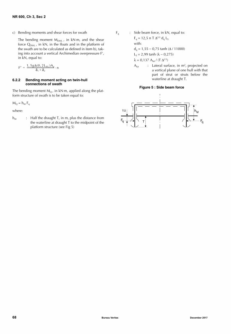
NR 600, Ch 3, Sec 2
c) Bending moments and shear forces for swath
The bending moment MDWL , in kN⋅m, and the shearforce QDWL , in kN, in the floats and in the platform ofthe swath are to be calculated as defined in item b), tak-ing into account a vertical Archimedian overpressure F’,in kN, equal to:
6.2.2 Bending moment acting on twin-hull connections of swath
The bending moment MQ , in kN⋅m, applied along the plat-form structure of swath is to be taken equal to:
MQ = hM Fq
where:
hM : Half the draught T, in m, plus the distance fromthe waterline at draught T to the midpoint of theplatform structure (see Fig 5)
Fq : Side beam force, in kN, equal to:
Fq = 12,5 n T Δ2/3 dq LS
with:dq = 1,55 − 0,75 tanh (Δ / 11000)
LS = 2,99 tanh (λ − 0,275)
λ = 0,137 Alat / (T Δ1/3)
Alat : Lateral surface, in m2, projected ona vertical plane of one hull with thatpart of strut or struts below thewaterline at draught T.
Figure 5 : Side beam force
F ′ 1 5, gΔ 0( 2LWL )Ap,δ1 δ2+
------------------------------------------------- n⋅=
���
���
��
��
68 Bureau Veritas December 2017
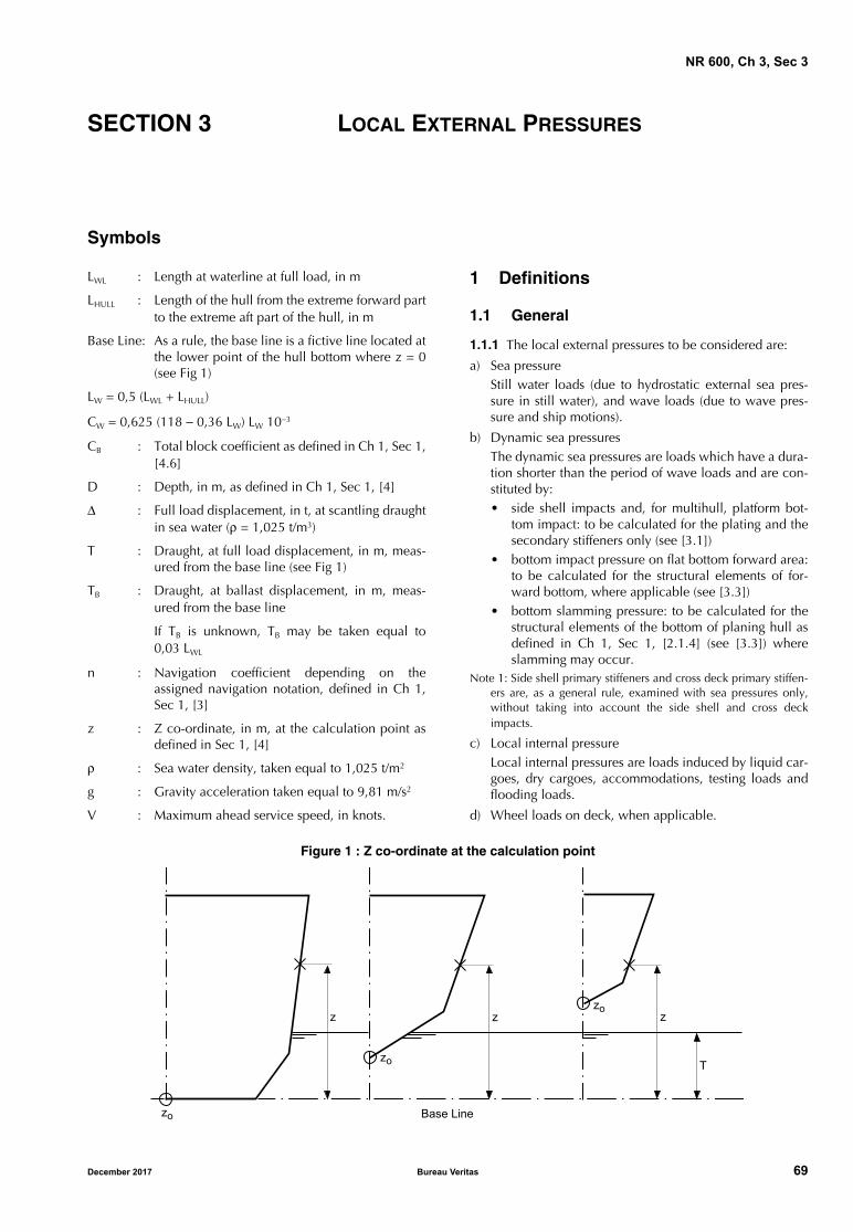
NR 600, Ch 3, Sec 3
SECTION 3 LOCAL EXTERNAL PRESSURES
Symbols
LWL : Length at waterline at full load, in m
LHULL : Length of the hull from the extreme forward partto the extreme aft part of the hull, in m
Base Line: As a rule, the base line is a fictive line located atthe lower point of the hull bottom where z = 0(see Fig 1)
LW = 0,5 (LWL + LHULL)
CW = 0,625 (118 − 0,36 LW) LW 10−3
CB : Total block coefficient as defined in Ch 1, Sec 1,[4.6]
D : Depth, in m, as defined in Ch 1, Sec 1, [4]
Δ : Full load displacement, in t, at scantling draughtin sea water (ρ = 1,025 t/m3)
T : Draught, at full load displacement, in m, meas-ured from the base line (see Fig 1)
TB : Draught, at ballast displacement, in m, meas-ured from the base line
If TB is unknown, TB may be taken equal to0,03 LWL
n : Navigation coefficient depending on theassigned navigation notation, defined in Ch 1,Sec 1, [3]
z : Z co-ordinate, in m, at the calculation point asdefined in Sec 1, [4]
ρ : Sea water density, taken equal to 1,025 t/m2
g : Gravity acceleration taken equal to 9,81 m/s2
V : Maximum ahead service speed, in knots.
1 Definitions
1.1 General
1.1.1 The local external pressures to be considered are:
a) Sea pressureStill water loads (due to hydrostatic external sea pres-sure in still water), and wave loads (due to wave pres-sure and ship motions).
b) Dynamic sea pressuresThe dynamic sea pressures are loads which have a dura-tion shorter than the period of wave loads and are con-stituted by:• side shell impacts and, for multihull, platform bot-
tom impact: to be calculated for the plating and thesecondary stiffeners only (see [3.1])
• bottom impact pressure on flat bottom forward area:to be calculated for the structural elements of for-ward bottom, where applicable (see [3.3])
• bottom slamming pressure: to be calculated for thestructural elements of the bottom of planing hull asdefined in Ch 1, Sec 1, [2.1.4] (see [3.3]) whereslamming may occur.
Note 1: Side shell primary stiffeners and cross deck primary stiffen-ers are, as a general rule, examined with sea pressures only,without taking into account the side shell and cross deckimpacts.
c) Local internal pressureLocal internal pressures are loads induced by liquid car-goes, dry cargoes, accommodations, testing loads andflooding loads.
d) Wheel loads on deck, when applicable.
Figure 1 : Z co-ordinate at the calculation point
��
�
���� ��
� �
���
��
December 2017 Bureau Veritas 69
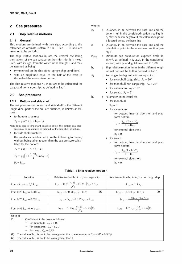
NR 600, Ch 3, Sec 3
2 Sea pressures
2.1 Ship relative motions
2.1.1 GeneralShip motions are defined, with their sign, according to thereference co-ordinate system in Ch 1, Sec 1, [5] and areassumed to be periodic.
The ship relative motions h1 are the vertical oscillatingtranslations of the sea surface on the ship side. It is meas-ured, with its sign, from the waterline at draught T and maybe assumed as being:• symmetrical on the ship sides (upright ship conditions)• with an amplitude equal to the half of the crest to
through of the encountered wave.
The ship relative motions h1, in m, are to be calculated forcargo and non cargo ships as defined in Tab 1.
2.2 Sea pressures
2.2.1 Bottom and side shellThe sea pressure on bottom and side shell in the differentlongitudinal parts of the hull are obtained, in kN/m2, as fol-lows:• for bottom structure:
Note 1: In case of important deadrise angle, the bottom sea pres-sure may be calculated as defined for the side shell structure.
• for side shell structure:the greater value obtained from the following formulae,without being taken greater than the sea pressure calcu-lated for the bottom:
PS = Pdmin
where:z0 : Distance, in m, between the base line and the
bottom hull in the considered section (see Fig 1).z0 may be taken negative if the calculation pointis located below the base line
z : Distance, in m, between the base line and thecalculation point in the considered section (seeFig 1)
Pdmin : Minimum sea pressure on exposed deck, inkN/m2, as defined in [2.2.2], in the consideredsection, with ϕ1 and ϕ3 taken equal to 1,00
h1 : Ship relative motion, in m, in the different longi-tudinal parts of the hull as defined in Tab 1
AR : Roll angle, in deg, to be taken equal to:• for monohull cargo ship: AR = 20°
• for monohull non cargo ship: AR = 25°
• for catamaran: AR = 10°
• for swath: AR = 5°
h2 : Parameter, in m, equal to: • for monohull:
h2 = 0
• for catamaran:- for bottom, internal side shell and plat-
form bottom:
- for external side shell:h2 = 0
• for swath:- for bottom, internal side shell and plat-
form bottom:
- for external side shell:h2 = 0
Table 1 : Ship relative motion h1
PS ρg T( h1 h2+ + z0 )–=
PS ρg T h1 h2 z–+ +( )=
PS ρg T0 8B, 1
2----------------+ ARsin z–
=
h2BWLi T h1+( )CB
BE BWLi–--------------------------------------=
h2BSTi T h1+( )CB
BE BSTi–------------------------------------=
Location Relative motion h1, in m, for cargo ship Relative motion h1, in m, for non cargo ship
from aft part to 0,25 LWL
from 0,25 LWL to 0,70 LWL (1) (2)
from 0,70 LWL to 0,85 LWL
from 0,85 LWL to fore part
Note 1:CH : Coefficient, to be taken as follows:
• for monohull: CH = 1,00• for catamaran: CH = 1,20• for swath: CH = 0,75
(1) The value of h1,m is not to be taken greater than the minimum of T and (D − 0,9 TB).(2) The value of h1,m is not to be taken greater than T.
h1 A, 0 63 4 35,CB
------------- 3 25,( )– h1 m,, h1 m,≥= h1 A, 1 1h1 m,,=
h1 m, 0 36nCW,= CB 0 7,+( ) h1 m, 0 38CW, 0 3,+( )n=
h1 E, h1 m, 0 125h1 FE,,+ h1 FE,≤= h1 E,1 4h, 1 m, 0 7h, 1 FE,+
2------------------------------------------------=
h1 FE, 1 2h1 m,4 35,
CB
------------- 3 25,– CH,= h1 FE, 1 7h, 1 m,
7 6,CB
0 1,------------ 6 4,– CH=
70 Bureau Veritas December 2017
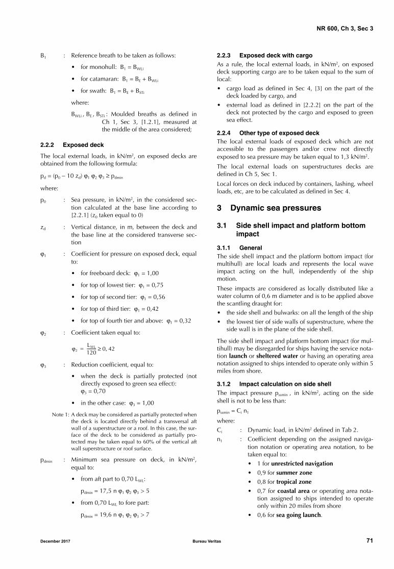
NR 600, Ch 3, Sec 3
B1 : Reference breath to be taken as follows:
• for monohull: B1 = BWLi
• for catamaran: B1 = BE + BWLi
• for swath: B1 = BE + BSTi
where:
BWLi , BE , BSTi : Moulded breaths as defined inCh 1, Sec 3, [1.2.1], measured atthe middle of the area considered;
2.2.2 Exposed deck
The local external loads, in kN/m2, on exposed decks areobtained from the following formula:
pd = (p0 − 10 zd) ϕ1 ϕ2 ϕ3 ≥ pdmin
where:
p0 : Sea pressure, in kN/m2, in the considered sec-tion calculated at the base line according to[2.2.1] (z0 taken equal to 0)
zd : Vertical distance, in m, between the deck andthe base line at the considered transverse sec-tion
ϕ1 : Coefficient for pressure on exposed deck, equalto:
• for freeboard deck: ϕ1 = 1,00
• for top of lowest tier: ϕ1 = 0,75
• for top of second tier: ϕ1 = 0,56
• for top of third tier: ϕ1 = 0,42
• for top of fourth tier and above: ϕ1 = 0,32
ϕ2 : Coefficient taken equal to:
ϕ3 : Reduction coefficient, equal to:
• when the deck is partially protected (notdirectly exposed to green sea effect):ϕ3 = 0,70
• in the other case: ϕ3 = 1,00
Note 1: A deck may be considered as partially protected whenthe deck is located directly behind a transversal aftwall of a superstructure or a roof. In this case, the sur-face of the deck to be considered as partially pro-tected may be taken equal to 60% of the vertical aftwall superstructure or roof surface.
pdmin : Minimum sea pressure on deck, in kN/m2,equal to:
• from aft part to 0,70 LWL:
pdmin = 17,5 n ϕ1 ϕ2 ϕ3 > 5
• from 0,70 LWL to fore part:
pdmin = 19,6 n ϕ1 ϕ2 ϕ3 > 7
2.2.3 Exposed deck with cargoAs a rule, the local external loads, in kN/m2, on exposeddeck supporting cargo are to be taken equal to the sum oflocal:
• cargo load as defined in Sec 4, [3] on the part of thedeck loaded by cargo, and
• external load as defined in [2.2.2] on the part of thedeck not protected by the cargo and exposed to greensea effect.
2.2.4 Other type of exposed deckThe local external loads of exposed deck which are notaccessible to the passengers and/or crew not directlyexposed to sea pressure may be taken equal to 1,3 kN/m2.
The local external loads on superstructures decks aredefined in Ch 5, Sec 1.
Local forces on deck induced by containers, lashing, wheelloads, etc, are to be calculated as defined in Sec 4.
3 Dynamic sea pressures
3.1 Side shell impact and platform bottom impact
3.1.1 GeneralThe side shell impact and the platform bottom impact (formultihull) are local loads and represents the local waveimpact acting on the hull, independently of the shipmotion.
These impacts are considered as locally distributed like awater column of 0,6 m diameter and is to be applied abovethe scantling draught for:
• the side shell and bulwarks: on all the length of the ship
• the lowest tier of side walls of superstructure, where theside wall is in the plane of the side shell.
The side shell impact and platform bottom impact (for mul-tihull) may be disregarded for ships having the service nota-tion launch or sheltered water or having an operating areanotation assigned to ships intended to operate only within 5miles from shore.
3.1.2 Impact calculation on side shellThe impact pressure pssmin , in kN/m2, acting on the sideshell is not to be less than:
pssmin = Ci n1
where:
Ci : Dynamic load, in kN/m2 defined in Tab 2.
n1 : Coefficient depending on the assigned naviga-tion notation or operating area notation, to betaken equal to:
• 1 for unrestricted navigation
• 0,9 for summer zone
• 0,8 for tropical zone
• 0,7 for coastal area or operating area nota-tion assigned to ships intended to operateonly within 20 miles from shore
• 0,6 for sea going launch.
ϕ2LWL
120---------- 0 42,≥=
December 2017 Bureau Veritas 71
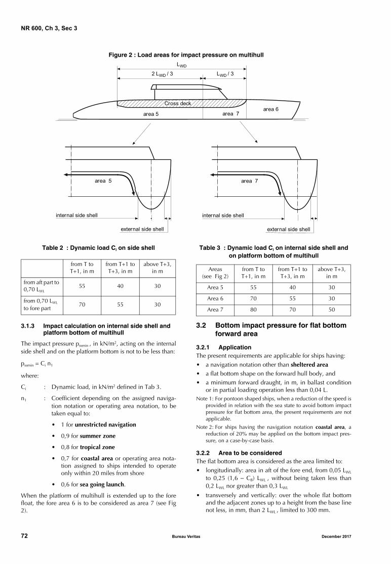
NR 600, Ch 3, Sec 3
Figure 2 : Load areas for impact pressure on multihull
Table 2 : Dynamic load Ci on side shell
3.1.3 Impact calculation on internal side shell and platform bottom of multihull
The impact pressure pssmin , in kN/m2, acting on the internalside shell and on the platform bottom is not to be less than:
pssmin = Ci n1
where:
Ci : Dynamic load, in kN/m2 defined in Tab 3.
n1 : Coefficient depending on the assigned naviga-tion notation or operating area notation, to betaken equal to:
• 1 for unrestricted navigation
• 0,9 for summer zone
• 0,8 for tropical zone
• 0,7 for coastal area or operating area nota-tion assigned to ships intended to operateonly within 20 miles from shore
• 0,6 for sea going launch.
When the platform of multihull is extended up to the forefloat, the fore area 6 is to be considered as area 7 (see Fig2).
Table 3 : Dynamic load Ci on internal side shell and on platform bottom of multihull
3.2 Bottom impact pressure for flat bottom forward area
3.2.1 ApplicationThe present requirements are applicable for ships having:• a navigation notation other than sheltered area• a flat bottom shape on the forward hull body, and• a minimum forward draught, in m, in ballast condition
or in partial loading operation less than 0,04 L.Note 1: For pontoon shaped ships, when a reduction of the speed is
provided in relation with the sea state to avoid bottom impactpressure for flat bottom area, the present requirements are notapplicable.
Note 2: For ships having the navigation notation coastal area, areduction of 20% may be applied on the bottom impact pres-sure, on a case-by-case basis.
3.2.2 Area to be consideredThe flat bottom area is considered as the area limited to:• longitudinally: area in aft of the fore end, from 0,05 LWL
to 0,25 (1,6 − CB) LWL , without being taken less than0,2 LWL nor greater than 0,3 LWL
• transversely and vertically: over the whole flat bottomand the adjacent zones up to a height from the base linenot less, in mm, than 2 LWL , limited to 300 mm.
area 6area 7area 5
LWD / 32 LWD / 3
LWD
area 5 area 7
Cross deck
internal side shell
external side shell
internal side shell
external side shell
from T to T+1, in m
from T+1 to T+3, in m
above T+3, in m
from aft part to 0,70 LWL
55 40 30
from 0,70 LWL to fore part
70 55 30
Areas (see Fig 2)
from T to T+1, in m
from T+1 to T+3, in m
above T+3, in m
Area 5 55 40 30
Area 6 70 55 30
Area 7 80 70 50
72 Bureau Veritas December 2017
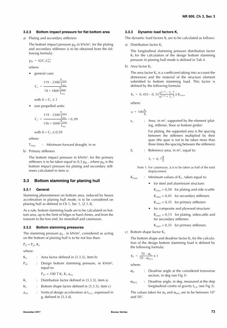
NR 600, Ch 3, Sec 3
3.2.3 Bottom impact pressure for flat bottom area
a) Plating and secondary stiffeners
The bottom impact pressure pBI in kN/m2, for the platingand secondary stiffeners is to be obtained from the fol-lowing formula:
where:
• general case:
with 0 < C1 ≤ 1
• non propelled units:
with 0 < C1 ≤ 0,59
where:
TFmin : Minimum forward draught, in m.
b) Primary stiffeners
The bottom impact pressure in kN/m2, for the primarystiffeners is to be taken equal to 0,3 pBI , where pBI is thebottom impact pressure for plating and secondary stiff-eners calculated in item a).
3.3 Bottom slamming for planing hull
3.3.1 General
Slamming phenomenon on bottom area, induced by heaveacceleration in planing hull mode, is to be considered onplaning hull as defined in Ch 1, Sec 1, [2.1.4].
As a rule, bottom slamming loads are to be calculated on bot-tom area, up to the limit of bilges or hard chines, and from thetransom to the fore end, for monohull and catamaran.
3.3.2 Bottom slamming pressures
The slamming pressure psl , in kN/m2, considered as actingon the bottom of planing hull is to be not less than:
Psl = Psl1 K2
where:
K2 : Area factor defined in [3.3.3], item b)
Psl1 : Design bottom slamming pressure, in kN/m2,equal to:
Psl1 = 100 T K1 K3 aCG
K1 : Distribution factor defined in [3.3.3], item a)
K3 : Bottom shape factor defined in [3.3.3], item c)
aCG : Vertical design acceleration at LCG , expressed ing, defined in [3.3.4].
3.3.3 Dynamic load factors Ki
The dynamic load factors Ki are to be calculated as follows:
a) Distribution factor K1
The longitudinal slamming pressure distribution factorK1 for the calculation of the design bottom slammingpressure in planing hull mode is defined in Tab 4.
b) Area factor K2
The area factor K2 is a coefficient taking into account thedimension and the material of the structure elementsubmitted to bottom slamming load. This factor isdefined by the following formula:
where:
sa : Area, in m2, supported by the element (plat-ing, stiffener, floor or bottom girder)
For plating, the supported area is the spacingbetween the stiffeners multiplied by theirspan (the span is not to be taken more thanthree times the spacing between the stiffeners)
Sr : Reference area, in m2, equal to:
Note 1: For catamaran, Δ is to be taken as half of the totaldisplacement.
K2min : Minimum values of K2 , taken equal to:
• for steel and aluminium structure:
K2min = 0,50 for plating and side scuttle
K2min = 0,45 for secondary stiffeners
K2min = 0,35 for primary stiffeners
• for composite and plywood structure:
K2min = 0,15 for plating, sidescuttle andfor secondary stiffeners
K2min = 0,35 for primary stiffeners.
c) Bottom shape factor K3
The bottom shape and deadrise factor K3 for the calcula-tion of the design bottom slamming load is defined bythe following formula:
where:
αd : Deadrise angle at the considered transversesection, in deg (see Fig 3)
αdCG : Deadrise angle, in deg, measured at the shiplongitudinal centre of gravity LCG (see Fig 3).
The values taken for αd and αdCG are to be between 10°and 50°.
pBI 62C1LWL0 6,=
C1
119 2300TFmin
LWL
------------–
78 1800TFmin
LWL
------------+------------------------------------------=
C1
119 2300TFmin
LWL
------------–
156 3600TFmin
LWL
------------+------------------------------------------ 0 09,+=
K2 0 455 0 35, u0 75, 1 7,–u0 75, 1 7,+---------------------------–, K2min≥=
u 100sa
Sr
----=
Sr 0 7ΔT---,=
K370 αd–
70 αdCG–------------------------ 1≤=
December 2017 Bureau Veritas 73
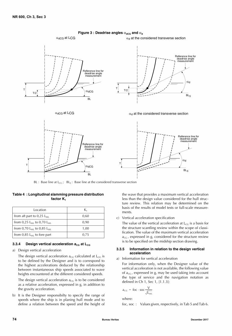
NR 600, Ch 3, Sec 3
Figure 3 : Deadrise angles αdCG and αd
BL : Base line at LCG ; BLS : Base line at the considered transverse section
Table 4 : Longitudinal slamming pressure distribution factor K1
3.3.4 Design vertical acceleration aCG at LCG
a) Design vertical acceleration
The design vertical acceleration aCG calculated at LCG isto be defined by the Designer and is to correspond tothe highest accelerations deduced by the relationshipbetween instantaneous ship speeds associated to waveheights encountered at the different considered speeds.
The design vertical acceleration aCG is to be consideredas a relative acceleration, expressed in g, in addition tothe gravity acceleration.
b) It is the Designer responsibilty to specify the range ofspeeds where the ship is in planing hull mode and todefine a relation between the speed and the height of
the wave that provides a maximum vertical accelerationless than the design value considered for the hull struc-ture review. This relation may be determined on thebasis of the results of model tests or full-scale measure-ments.
c) Vertical acceleration specification
The value of the vertical acceleration at LCG is a basis forthe structure scantling review within the scope of classi-fication. The value of the maximum vertical accelerationaCG , expressed in g, considered for the structure reviewis to be specified on the midship section drawing.
3.3.5 Information in relation to the design vertical acceleration
a) Information for vertical accelerationFor information only, when the Designer value of thevertical acceleration is not available, the following valueof aCG , expressed in g, may be used taking into accountthe type of service and the navigation notation asdefined in Ch 1, Sec 1, [1.1.3]:
where:foc, soc : Values given, respectively, in Tab 5 and Tab 6.
TT/2
Reference line fordeadrise anglemeasurement
T
Reference line fordeadrise anglemeasurement
T/2
Reference line fordeadrise anglemeasurement
T
Reference line fordeadrise anglemeasurement
T
BL
BL
BLS
BLS
Location K1
from aft part to 0,25 LWL 0,60
from 0,25 LWL to 0,70 LWL 0,90
from 0,70 LWL to 0,85 LWL 1,00
from 0,85 LWL to fore part 0,75
aCG foc soc⋅ VLWL
------------=
74 Bureau Veritas December 2017

NR 600, Ch 3, Sec 3
b) Information about relation between instantaneousspeeds and associated wave heights
For information only, where the relation between the speedsand the associated wave heights is not defined by theDesigner, the following formula may be used betweeninstantaneous speeds Vx and associated wave heights HS inplaning hull mode compatible with the design accelerationconsidered for the hull structure check:
where:HS : Associated wave height, in m, to the considered
speed Vx
aCG : Design vertical acceleration, in g, consideredfor the structure scantling review
Vx : Speed considered, in knotsαdCG : Deadrise angle, in deg, at LCG . In this formula,
αdCG is to be taken between 10° and 30°
Table 5 : Values of foc
τ : Trim angle during navigation, in deg, to betaken not less than 4°
BW : Maximum breadth at full load waterline. Forcatamarans, BW is to be taken as the sum of thebreadth of each hull
KFR , KHS : Coefficients defined as follows:
• for planing hull for which V/L0,5 ≥ 3 andΔ/(0,01L)3 ≥ 3500:
KHS = 1
• for planing hull for which V/L0,5 < 3 orΔ/(0,01L)3 < 3500:
KHS = HS / T
The formula of HS is only valid if all the following relation-ships are simultaneously complied with:
• 3500 < Δ / (0,01 LWL)3 < 8700
• 3 < LWL / BW < 5
• 10° < αdCG < 30°
• 0,2 < HS / BW < 0,7
• 3,0 < V / (LWL)0,5 < 10,9
Table 6 : Values of soc
Type of service
Passenger, Ferry, Cargo
Supply, Fishing
Pilot, Patrol
Rescue
foc 0,666 1,000 1,333 1,666
Note 1: As a rule, foc is to be taken equal to 0,666 forlaunch and sea going launch.
aCG
50 αdCG–( ) τ16------ 0 75,+
3555CB
------------------------------------------------------------- HS
T------ 0 084
BW
T-------,+
KFRKHS= KFRVx
L------- 2
=
KFR 0 8, 1 6Vx
L-------,+=
Navigation notation Unrestricted navigation Summer zoneTropical zone or coastal area (3)
Sheltered area (4)
Wave height (for information only) (1)
Hs ≥ 4,0 m or 2,5 m ≤ Hs < 4,0 m 0,5 m < Hs < 2,5 m Hs ≤ 0,5 m
soc CF (2) 0,30 0,23 0,14
(1) Wave heights, given for information only, in relation with the navigation notations are wave heights which are exceeded for anaverage of not more than 10% of the year.
(2) For passenger, ferry and cargo ship, their seaworthiness in this condition is to be ascertained. In general, the value of socshould not be less than the values given in this Table, with:
(3) Not applicable to ships having the type of service “Rescue”.(4) Not applicable to ships having the type of service “Pilot, Patrol” or “Rescue”.
As a rule, applicable to ships having the navigation notation sea going launch or launch.
CF 0 2, 0 6,V LWL⁄---------------------+ 0 32,≥=
December 2017 Bureau Veritas 75
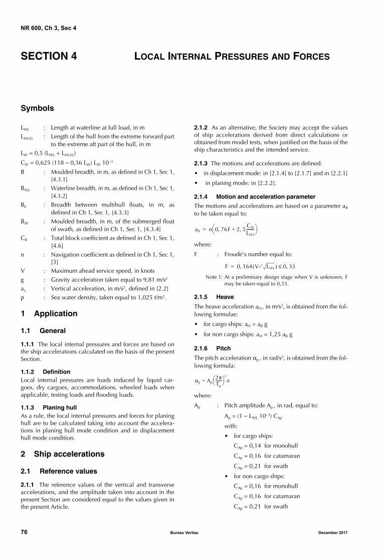
NR 600, Ch 3, Sec 4
SECTION 4 LOCAL INTERNAL PRESSURES AND FORCES
Symbols
LWL : Length at waterline at full load, in mLHULL : Length of the hull from the extreme forward part
to the extreme aft part of the hull, in mLW = 0,5 (LWL + LHULL)
CW = 0,625 (118 − 0,36 LW) LW 10−3
B : Moulded breadth, in m, as defined in Ch 1, Sec 1,[4.3.1]
BWL : Waterline breadth, in m, as defined in Ch 1, Sec 1,[4.3.2]
BE : Breadth between multihull floats, in m, asdefined in Ch 1, Sec 1, [4.3.3]
BSF : Moulded breadth, in m, of the submerged floatof swath, as defined in Ch 1, Sec 1, [4.3.4]
CB : Total block coefficient as defined in Ch 1, Sec 1,[4.6]
n : Navigation coefficient as defined in Ch 1, Sec 1,[3]
V : Maximum ahead service speed, in knotsg : Gravity acceleration taken equal to 9,81 m/s2
az : Vertical acceleration, in m/s2, defined in [2.2]ρ : Sea water density, taken equal to 1,025 t/m3.
1 Application
1.1 General
1.1.1 The local internal pressures and forces are based onthe ship accelerations calculated on the basis of the presentSection.
1.1.2 DefinitionLocal internal pressures are loads induced by liquid car-goes, dry cargoes, accommodations, wheeled loads whenapplicable, testing loads and flooding loads.
1.1.3 Planing hullAs a rule, the local internal pressures and forces for planinghull are to be calculated taking into account the accelera-tions in planing hull mode condition and in displacementhull mode condition.
2 Ship accelerations
2.1 Reference values
2.1.1 The reference values of the vertical and transverseaccelerations, and the amplitude taken into account in thepresent Section are considered equal to the values given inthe present Article.
2.1.2 As an alternative, the Society may accept the valuesof ship accelerations derived from direct calculations orobtained from model tests, when justified on the basis of theship characteristics and the intended service.
2.1.3 The motions and accelerations are defined:
• in displacement mode: in [2.1.4] to [2.1.7] and in [2.2.1]
• in planing mode: in [2.2.2].
2.1.4 Motion and acceleration parameter
The motions and accelerations are based on a parameter aB
to be taken equal to:
where:
F : Froude’s number equal to:
Note 1: At a preliminary design stage when V is unknown, Fmay be taken equal to 0,33.
2.1.5 Heave
The heave acceleration aH , in m/s2, is obtained from the fol-lowing formulae:
• for cargo ships: aH = aB g
• for non cargo ships: aH = 1,25 aB g
2.1.6 Pitch
The pitch acceleration αp , in rad/s2, is obtained from the fol-lowing formula:
where:
Ap : Pitch amplitude Ap , in rad, equal to:
Ap = (1 − LWL 10−3) CAp
with:
• for cargo ships:
CAp = 0,14 for monohull
CAp = 0,16 for catamaran
CAp = 0,21 for swath
• for non cargo ships:
CAp = 0,16 for monohull
CAp = 0,16 for catamaran
CAp = 0,21 for swath
aB n 0 76F, 2 5CW
LWL
--------,+ =
F 0 164 V LWL⁄( ), 0 33,≤=
αp Ap= 2πTp-------
2
n
76 Bureau Veritas December 2017
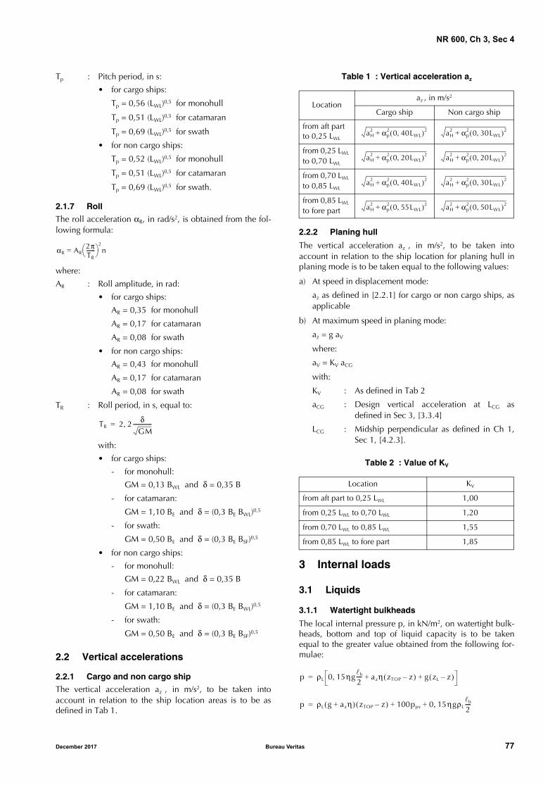
NR 600, Ch 3, Sec 4
Tp : Pitch period, in s:
• for cargo ships:
Tp = 0,56 (LWL)0,5 for monohull
Tp = 0,51 (LWL)0,5 for catamaran
Tp = 0,69 (LWL)0,5 for swath
• for non cargo ships:
Tp = 0,52 (LWL)0,5 for monohull
Tp = 0,51 (LWL)0,5 for catamaran
Tp = 0,69 (LWL)0,5 for swath.
2.1.7 Roll
The roll acceleration αR, in rad/s2, is obtained from the fol-lowing formula:
where:
AR : Roll amplitude, in rad:
• for cargo ships:
AR = 0,35 for monohull
AR = 0,17 for catamaran
AR = 0,08 for swath
• for non cargo ships:
AR = 0,43 for monohull
AR = 0,17 for catamaran
AR = 0,08 for swath
TR : Roll period, in s, equal to:
with:
• for cargo ships:
- for monohull:
GM = 0,13 BWL and δ = 0,35 B
- for catamaran:
GM = 1,10 BE and δ = (0,3 BE BWL)0,5
- for swath:
GM = 0,50 BE and δ = (0,3 BE BSF)0,5
• for non cargo ships:
- for monohull:
GM = 0,22 BWL and δ = 0,35 B
- for catamaran:
GM = 1,10 BE and δ = (0,3 BE BWL)0,5
- for swath:
GM = 0,50 BE and δ = (0,3 BE BSF)0,5
2.2 Vertical accelerations
2.2.1 Cargo and non cargo ship
The vertical acceleration az , in m/s2, to be taken intoaccount in relation to the ship location areas is to be asdefined in Tab 1.
Table 1 : Vertical acceleration az
2.2.2 Planing hull
The vertical acceleration az , in m/s2, to be taken intoaccount in relation to the ship location for planing hull inplaning mode is to be taken equal to the following values:
a) At speed in displacement mode:
az as defined in [2.2.1] for cargo or non cargo ships, asapplicable
b) At maximum speed in planing mode:
az = g aV
where:
aV = KV aCG
with:
KV : As defined in Tab 2
aCG : Design vertical acceleration at LCG asdefined in Sec 3, [3.3.4]
LCG : Midship perpendicular as defined in Ch 1,Sec 1, [4.2.3].
Table 2 : Value of KV
3 Internal loads
3.1 Liquids
3.1.1 Watertight bulkheads
The local internal pressure p, in kN/m2, on watertight bulk-heads, bottom and top of liquid capacity is to be takenequal to the greater value obtained from the following for-mulae:
αR AR= 2πTR-------
2
n
TR 2 2 δGM--------------,=
Locationaz , in m/s2
Cargo ship Non cargo ship
from aft part to 0,25 LWL
from 0,25 LWL to 0,70 LWL
from 0,70 LWL to 0,85 LWL
from 0,85 LWL to fore part
Location KV
from aft part to 0,25 LWL 1,00
from 0,25 LWL to 0,70 LWL 1,20
from 0,70 LWL to 0,85 LWL 1,55
from 0,85 LWL to fore part 1,85
aH2 αp
2 0 40LWL,( )2+ aH2 αp
2 0 30LWL,( )2+
aH2 αp
2 0 20LWL,( )2+ aH2 αp
2 0 20LWL,( )2+
aH2 αp
2 0 40LWL,( )2+ aH2 αp
2 0 30LWL,( )2+
aH2 αp
2 0 55LWL,( )2+ aH2 αp
2 0 50LWL,( )2+
p ρL 0 15ηgb
2----, azη zTOP z–( ) g zL z–( )+ +=
p ρL g azη+( ) zTOP z–( ) 100ppv 0 15ηgρLb
2----,+ +=
December 2017 Bureau Veritas 77
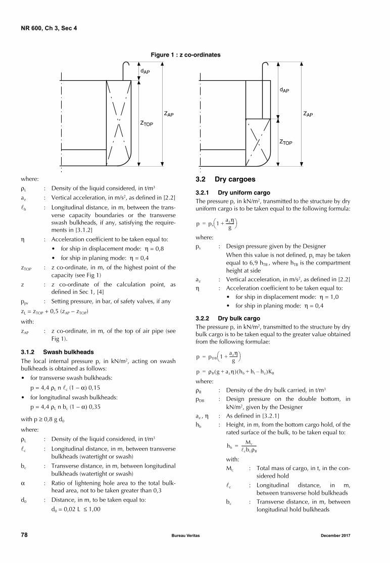
NR 600, Ch 3, Sec 4
Figure 1 : z co-ordinates
where:
ρL : Density of the liquid considered, in t/m3
az : Vertical acceleration, in m/s2, as defined in [2.2]
b : Longitudinal distance, in m, between the trans-verse capacity boundaries or the transverseswash bulkheads, if any, satisfying the require-ments in [3.1.2]
η : Acceleration coefficient to be taken equal to:
• for ship in displacement mode: η = 0,8
• for ship in planing mode: η = 0,4
zTOP : z co-ordinate, in m, of the highest point of thecapacity (see Fig 1)
z : z co-ordinate of the calculation point, asdefined in Sec 1, [4]
ppv : Setting pressure, in bar, of safety valves, if any
zL = zTOP + 0,5 (zAP − zTOP)
with:
zAP : z co-ordinate, in m, of the top of air pipe (seeFig 1).
3.1.2 Swash bulkheads
The local internal pressure p, in kN/m2, acting on swashbulkheads is obtained as follows:
• for transverse swash bulkheads:
p = 4,4 ρL n c (1 − α) 0,15
• for longitudinal swash bulkheads:
p = 4,4 ρL n bc (1 − α) 0,35
with p ≥ 0,8 g d0
where:
ρL : Density of the liquid considered, in t/m3
c : Longitudinal distance, in m, between transversebulkheads (watertight or swash)
bc : Transverse distance, in m, between longitudinalbulkheads (watertight or swash)
α : Ratio of lightening hole area to the total bulk-head area, not to be taken greater than 0,3
d0 : Distance, in m, to be taken equal to:
d0 = 0,02 L ≤ 1,00
3.2 Dry cargoes
3.2.1 Dry uniform cargoThe pressure p, in kN/m2, transmitted to the structure by dryuniform cargo is to be taken equal to the following formula:
where:ps : Design pressure given by the Designer
When this value is not defined, ps may be takenequal to 6,9 hTB , where hTB is the compartmentheight at side
az : Vertical acceleration, in m/s2, as defined in [2.2]η : Acceleration coefficient to be taken equal to:
• for ship in displacement mode: η = 1,0• for ship in planing mode: η = 0,4
3.2.2 Dry bulk cargoThe pressure p, in kN/m2, transmitted to the structure by drybulk cargo is to be taken equal to the greater value obtainedfrom the following formulae:
where:ρB : Density of the dry bulk carried, in t/m3
pDB : Design pressure on the double bottom, inkN/m2, given by the Designer
az , η : As defined in [3.2.1]hb : Height, in m, from the bottom cargo hold, of the
rated surface of the bulk, to be taken equal to:
with:Mc : Total mass of cargo, in t, in the con-
sidered hold
c : Longitudinal distance, in m,between transverse hold bulkheads
bc : Transverse distance, in m, betweenlongitudinal hold bulkheads
dAP
ZTOP
ZAP
dAP
ZTOP
ZAP
p ps 1azηg---------+
=
p pDB 1azηg---------+
=
p ρB g azη+( ) hb ht hz–+( )KB=
hbMc
cbcρB
----------------=
78 Bureau Veritas December 2017
NR 600, Ch 3, Sec 4
ht : Height, in m, of the bulk cargo upper surface, tobe taken equal to:
with:
ϕ : Angle of repose, in deg, of the bulkcargo considered drained andremoved (in absence of precise eval-uation, ϕ may be taken equal to 30°)
hz : Vertical distance, in m, from the bottom hold tothe calculation point
KB : Coefficient, taken equal to:
• KB = 0,4 when the dry bulk pressure isapplied on a vertical structure element
• KB = 1,0 in the other cases.
3.2.3 Dry unit cargo
The forces transmitted to the hull structures are to be deter-mined on the basis of the forces Fz , in kN, calculated as fol-lows:
Fz = M (g + az η)
where:
az : Reference value of the vertical accelerationdefined in [2.2]
M : Total mass, in t, of the dry unit cargo considered
η : As defined in [3.2.1].
Where deemed necessary by the Society for dry unit cargolocated above the water line level, the horizontal and verti-cal forces applied to the dry unit cargo, in kN, induced byroll may be taken into account in addition to Fz .
In this case, the forces FT and FV , in kN, transmitted to thehull structure and to be added to Fz may be calculated asfollows:
• transverse force:
FT = 0,7 M αR (z − Tmin)
• vertical force:
FV = 0,7 M αR y
where:
M : Mass, in t, of the dry unit cargo considered
αR : Roll acceleration, in m/s2, as defined in [2.1.7]
y, z : Transverse and vertical co-ordinates of the cen-tre of gravity of the dry unit considered
Tmin : Minimum draught of the ship, in m.
3.3 Wheeled loads
3.3.1 Local forces
Caterpillar trucks and unusual vehicles are considered bythe Society on a case-by-case basis.
The load supported by the crutches of semi-trailers, han-dling machines and platforms is considered by the Societyon a case-by-case basis.
The forces transmitted through the tyres are comparable tothe pressure uniformly distributed on the tyre print, thedimensions of which are to be indicated by the Designertogether with the information concerning the arrangementof wheels on axles, the load per axle and the tyre pressures.
For vehicles on rails, all the forces transmitted are to be con-sidered as concentrated.
The forces FW , in kN, transmitted to the hull structure are tobe determined as follows:
• in the general case:
FW = M (g + α az)
• in harbour conditions, for fork-lift trucks and vehicles onexternal ramp:
FW = 1,1 M g
where:
M : Force, in t, applied by one wheel and calculatedas follows:
with:
QA : Axle load, in t. For fork-lift trucks,QA is to be taken equal to the totalmass of the vehicle, including themass of the cargo handled, appliedto one axle only
nW : Number of wheels for the axle con-sidered
α : Coefficient taken equal to:
• in the general case: α = 0,5
• for landing gears of trailers: α = 1,0
az : Reference value of the vertical accelerationdefined in [2.2].
4 Loads on deck
4.1 Exposed deck
4.1.1 The local external loads, in kN/m2, on exposed deckare to be as defined in Sec 3, [2.2.2].
Table 3 : Minimum values of ps
htbc
4----- ϕ
2---tan=
Accommodation deck ps , in kN/m2
Large public spaces such as restaurants, halls, cinema, lounges
5,0
Large rooms such as rooms with fixed furni-ture, games and hobbies rooms, hospitals
3,0
Cabins 3,0
Other compartments 2,5
MQA
nW
-------=
December 2017 Bureau Veritas 79
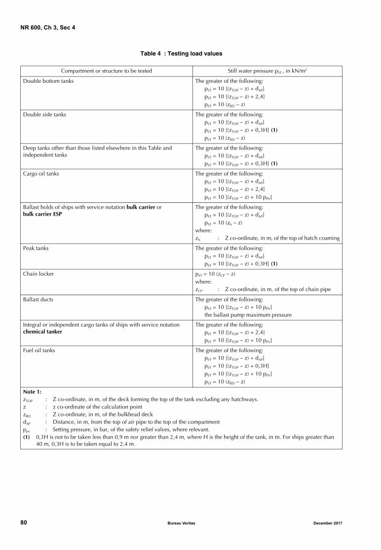
NR 600, Ch 3, Sec 4
Table 4 : Testing load values
Compartment or structure to be tested Still water pressure pST , in kN/m2
Double bottom tanks The greater of the following:pST = 10 [(zTOP − z) + dAP]pST = 10 [(zTOP − z) + 2,4]pST = 10 (zBD − z)
Double side tanks The greater of the following:pST = 10 [(zTOP − z) + dAP]pST = 10 [(zTOP − z) + 0,3H] (1)pST = 10 (zBD − z)
Deep tanks other than those listed elsewhere in this Table and independent tanks
The greater of the following:pST = 10 [(zTOP − z) + dAP]pST = 10 [(zTOP − z) + 0,3H] (1)
Cargo oil tanks The greater of the following:pST = 10 [(zTOP − z) + dAP]pST = 10 [(zTOP − z) + 2,4]pST = 10 [(zTOP − z) + 10 pPV]
Ballast holds of ships with service notation bulk carrier or bulk carrier ESP
The greater of the following:pST = 10 [(zTOP − z) + dAP]pST = 10 (zh − z)
where:zh : Z co-ordinate, in m, of the top of hatch coaming
Peak tanks The greater of the following:pST = 10 [(zTOP − z) + dAP]pST = 10 [(zTOP − z) + 0,3H] (1)
Chain locker pST = 10 (zCP − z)where:zCP : Z co-ordinate, in m, of the top of chain pipe
Ballast ducts The greater of the following:pST = 10 [(zTOP − z) + 10 pPV]the ballast pump maximum pressure
Integral or independent cargo tanks of ships with service notation chemical tanker
The greater of the following:pST = 10 [(zTOP − z) + 2,4]pST = 10 [(zTOP − z) + 10 pPV]
Fuel oil tanks The greater of the following:pST = 10 [(zTOP − z) + dAP]pST = 10 [(zTOP − z) + 0,3H]pST = 10 [(zTOP − z) + 10 pPV]pST = 10 (zBD − z)
Note 1:zTOP : Z co-ordinate, in m, of the deck forming the top of the tank excluding any hatchways.z : z co-ordinate of the calculation pointzBD : Z co-ordinate, in m, of the bulkhead deckdAP : Distance, in m, from the top of air pipe to the top of the compartmentppv : Setting pressure, in bar, of the safety relief valves, where relevant.(1) 0,3H is not to be taken less than 0,9 m nor greater than 2,4 m, where H is the height of the tank, in m. For ships greater than
40 m, 0,3H is to be taken equal to 2,4 m.
80 Bureau Veritas December 2017
NR 600, Ch 3, Sec 4
4.2 Accommodation deck
4.2.1 The pressure on accommodation deck is obtained, inkN/m2, from the following formula:
where:az : Reference value of the vertical acceleration
defined in [2.2]η : As defined in [3.2.1]ps : Pressure defined by the Designer, to be taken at
least equal to the values given in Tab 3.
4.3 Specific loads on deck
4.3.1 Specific loads on deck such as wheeled loads, dryunit cargo, containers, are to be determined as defined inArticle [3].
4.3.2 Machinery spacesThe pressure on decks and platforms located in the machin-ery spaces is obtained, in kN/m2, from the following formula:
where:az : Reference value of the vertical acceleration
defined in [2.2]η : As defined in [3.2.1]ps : Pressure defined by the Designer
When this value is not defined, ps may be takenequal to 10 kN/m2.
5 Testing loads
5.1 General
5.1.1 The testing loads acting on the structures subject totank testing are obtained, in kN/m2, from the formulae inTab 4.
Compartments not defined in Tab 4 are to be tested inaccordance with NR467 Steel Ships, Pt B, Ch 5, Sec 6.
6 Flooding loads
6.1 General
6.1.1 The internal pressure pfl to be considered on thestructure of boundaries of watertight compartments notintended to carry liquids (bulkheads and decks with excep-tion for bottom and side shell structures) is to be obtained,in kN/m2, from the following formula:
pfl = 1,5 ρ g n df
without being taken less than 0,8 g d0
where:
df : Distance, in m, form the calculation point to thebulkhead deck (or freeboard deck when there isno bulkhead deck). Where the results of dam-age stability calculations are available, thedeepest equilibrium waterline may be consid-ered in lieu of the bulkhead deck
d0 : Distance, in m, to be taken equal to:
d0 = 1 if LWL ≤ 50 m
d0 = 0,02 LWL if LWL > 50 m
p ps 1azηg---------+
=
p ps 1azηg---------+
=
December 2017 Bureau Veritas 81

NR 600, Ch 3, Sec 4
82 Bureau Veritas December 2017
NR 600
Chapter 4
HULL SCANTLING
SECTION 1 GENERAL
SECTION 2 GLOBAL STRENGTH ANALYSIS
SECTION 3 LOCAL PLATING SCANTLING
SECTION 4 LOCAL SECONDARY STIFFENER SCANTLING
SECTION 5 LOCAL PRIMARY STIFFENER SCANTLING
SECTION 6 STIFFENER BRACKETS SCANTLING AND STIFFENER END CONNECTIONS
SECTION 7 PILLAR SCANTLING
APPENDIX 1 CALCULATION OF THE CRITICAL BUCKLING STRESSES
APPENDIX 2 HULL SCANTLING CHECK WITH LOCAL AND GLOBAL STRESSES COMBINATION CRITERIA
December 2017 Bureau Veritas 83

84 Bureau Veritas December 2017
NR 600, Ch 4, Sec 1
December 2017 Bureau Veritas 85
SECTION 1 GENERAL
1 Materials
1.1 General
1.1.1 General
The requirements for the determination of the hull scant-lings defined in the present Chapter are applicable to shiphull made totally or partly of:
• steel (ordinary or high tensile)
• aluminium alloys
• composites materials
• wood (strip planking or plywood).
Ships built with different hull materials are to be specificallyconsidered on a case-by-case basis.
Attention is drawn to the selection of building materialswhich is not only to be determined from strength considera-tion, but should also give consideration to structural fireprotection and associated class requirements or FlagAdministration requirements where applicable.
1.1.2 Characteristics of materials
The main characteristics of materials to consider for hullscantlings are defined in Ch 1, Sec 2.
2 Structure scantling approach
2.1 General
2.1.1 General case
As a rule, the global hull girder strength and the localstrength are examined independently.
2.1.2 Particular cases
The combination of global hull girder strength and the localstrength may be carried out as defined in Ch 1, Sec 3,[2.1.2]. In this case, the requirements defined in NR467Steel Ships, Chapter 7, dedicated for Cargo Ships greaterthan 65 m or Non Cargo Ships greater than 90 m, may befully applied the Society.
2.2 Global strength analysis
2.2.1 Analysis
The global hull girder longitudinal strength and the globalstrength of multihull are to be checked according to Sec 2,taking into account the:
• global loads as defined in Ch 3, Sec 2, and
• permissible stresses and safety factors as defined in Ch 2,Sec 3.
2.2.2 Check
The global strength analysis is carried out in order to check,for the elements contributing to the global hull strength, thehull girder stresses in relation to:
• the maximum permissible global stress, and
• buckling criteria.
2.3 Local scantling analysis
2.3.1 Analysis
The local scantling of panels, secondary stiffeners and pri-mary stiffeners is to be checked according to Sec 3 for plat-ing, Sec 4 for secondary stiffeners and Sec 5 for primarystiffeners, taking into account the:
• local loads as defined in Ch 3, Sec 3 for external pres-sure, Ch 3, Sec 4 for internal pressure and Ch 5, Sec 1for superstructures, and
• permissible stresses and safety factors as defined in Ch 2,Sec 3.
The type of local lateral pressures to be considered are:
• wave loads
• dynamic loads:
- bottom slamming pressures for planing hull, whenslamming may occur
- side shell impacts (and platform bottom impacts formultihull) for all types of ships, where applicable(see Ch 3, Sec 3, [3.1])
• deck loads and superstructure pressures
• bulkhead and tank loads
• wheeled loads.
2.3.2 Check
The local strength analysis is carried out in order to check,for the plating, secondary and primary stiffeners, the localstresses in relation to:
• the maximum permissible local stress, and
• local buckling criteria, where applicable.
2.4 Specific cases
2.4.1 Specific scantling criteria in relation to the servicenotation of the ships are defined in Ch 6, Sec 1.
NR 600, Ch 4, Sec 2
SECTION 2 GLOBAL STRENGTH ANALYSIS
1 General
1.1 Application
1.1.1 The global strength analysis is to be carried out inorder to check the hull girder stress in relation to maximumpermissible stress and buckling stress (see [2.2] and [2.3]).
1.1.2 Material
The global strength analysis of monohull and multihull is tobe carried out taking into account:
• for steel structure: the present Section
• for aluminium structure: the present Section and NR561Aluminium Ships
• for composite structure: the present Section and NR546Composite Ships.
1.1.3 Application
a) Monohull ships and float of multihull:
For monohull ships and for floats of multihull, the globalhull girder longitudinal strength is to be examined in thefollowing cases:
• ships with length greater than 40 m, and 30 m forship built in composite material, or
• ships having large openings in decks or significantgeometrical structure discontinuity at bottom ordeck, or
• ships with transverse framing systems, or
• ships with deck structure built with large spacing ofsecondary stiffeners, or
• cargo ship as defined in Ch 1, Sec 1, [2.1.2], or
• where deemed appropriate by the Society.
For ships not covered by the above cases, the hull girderstrength is considered satisfied when local scantlings arein accordance with requirements defined in Sec 3 andin Sec 4.
b) Platform structure of multihull:
As a rule, the global transverse strength of platform ofmultihull is to be examined for all types of multihull.
1.2 Global strength calculation
1.2.1 General
The global strength of monohull and multihull are to be cal-culated as defined in [3] and [4].
1.2.2 Where a member contributing to the longitudinaland/or transversal strength is made in material other thansteel with a Young’s modulus E equal to 2,06 105 N/mm2,
the steel equivalent sectional area that may be included forthe calculation of the inertia of the considered section isobtained, in m2, from the following formula:
where:AM : Sectional area, in m2, of the member under con-
siderationE : Young modulus, in N/mm2, of the considered
member.
1.2.3 Finite element calculationThe global strength analysis may also be examined with aFinite Elements Analysis submitted by the Designer. In thiscase, and where large openings are provided in side shelland/or in primary transverse cross structure of platform ofmultihull for windows, doors..., a special attention is to bepaid to ensure a realistic modelling of the bending andshear strength of the jambs between openings.
2 Global strength check
2.1 General
2.1.1 The global analysis check is to be successively car-ried out taking into account the scantling criteria based onmaximum stress check (see [2.2]) and on buckling check(see [2.3]).The global analysis check is to be carried out in the follow-ing areas of the hull:• in head sea condition (for monohull and multihull):
Along the ship from 0,3L to 0,7L from the aft end• in quartering sea (for multihull only):
Along the float from aft to fore end, and in way of eachprimary transverse cross structure of the platform.
2.2 Maximum stress check
2.2.1 Steel and aluminium structureIt is to be checked that the actual normal stresses σA, inN/mm2, and the actual shear stresses τA, in N/mm2, calcu-lated according to [3] and, for multihull, to [4] are in com-pliance with the following criteria:
where:σglam : Global bending permissible stress, in N/mm2, as
defined in Ch 2, Sec 3τglam : Global shear permissible stress, in N/mm2, as
defined in Ch 2, Sec 3.
ASEE
2 06.105,----------------------AM=
σA σglam≤
τA τglam≤
86 Bureau Veritas December 2017
NR 600, Ch 4, Sec 2
2.2.2 Composite structure
It is to be checked that the actual normal stresses and shearstresses, calculated according to [3] and, for multihull, to [4]are in compliance with the criteria defined in Ch 2, Sec 3,[3.1].
2.3 Buckling check
2.3.1 Plate panel
a) Steel and aluminium plate panel:
It is to be checked that the actual normal stresses σA andshear stresses τA calculated according to Article [3] and,for multihull, to Article [4] are in compliance with thefollowing criteria:
• under simple compression:
• under double compression and shear (for platformbottom and deck of catamaran):
• under shear:
where:
σc, τc : Critical buckling stress, in N/mm2, in com-pression and in shear as defined in App 1 forsteel plating and in NR561 AluminiumShips for aluminium plating
SF : Permissible safety factor defined in Ch 2,Sec 3, [2]
σc,a, σc,b : Critical buckling stresses, in N/mm2, in dou-ble compression as defined in App 1 forsteel plating and in NR561 AluminiumShips for aluminium plating
σB : Actual compression stress acting on side“b”, in N/mm2
b) Plate panel in composite material:
It is to be checked that the actual normal stresses σA andshear stresses τA calculated according to Article [3] and,for multihull, to Article [4] are in compliance with thefollowing criteria:
where:
σc, τc, : Critical buckling stress, in N/mm2, in com-pression and in shear in the whole panel asdefined in NR546 Composite Ships (Sec 6,[4])
SFB : Permissible safety factor defined in Ch 2,Sec 3, [3.2.3].
2.3.2 Secondary stiffeners
As a rule, the buckling check is to be carried out for stiffen-ers parallel to the direction of compression only.
It is to be checked that the actual normal stresses σA calcu-lated according to Article [3] and, for multihull, to Article[4] is in compliance with the following criteria:
where:
σc : Critical buckling stress, in N/mm2, in compres-sion as defined in:
• App 1 for stiffeners in steel
• NR561 Aluminium Ships for stiffeners inaluminium
• NR546 Composite Ships for stiffeners incomposite materials
SFB : Permissible rule safety factors defined in Ch 2,Sec 3, [2] for steel and aluminium stiffeners, andin Ch 2, Sec 3, [3.2.3] for composite stiffeners.
2.3.3 Primary stiffeners
The buckling check for primary stiffeners is to be carried outas defined in [2.3.2] for secondary stiffeners.
3 Calculation of global strength for monohull ship
3.1 General
3.1.1 The calculation of the hull girder strength characteris-tics is to be carried out taking into account all the longitudi-nal continuous structural elements of the hull.
A superstructure extending over at least 0,4 L may be con-sidered as contributing to the longitudinal strength.
The transverse sectional areas of openings such as deckhatches, side shell ports, side shell and superstructure doorsand windows, in the members contributing to the longitudi-nal hull girder strength, are to be deducted from the consid-ered transverse section.
Lightening holes, draining holes and single scallops in lon-gitudinal stiffeners need not be deducted if their height isless than 0,25 hW without being greater than 75 mm, wherehW is the web height, in mm, of the considered longitudinal.
σAσc
SF------≤
σA
σc a,---------
1 9, σB
σc b,---------
1 9, τA
τc
-----1 9,
+ + 1≤
τAτc
SF------≤
σAσc
SFB
--------≤
τAτc
SFB
--------≤
σAσc
SFB
--------≤
December 2017 Bureau Veritas 87
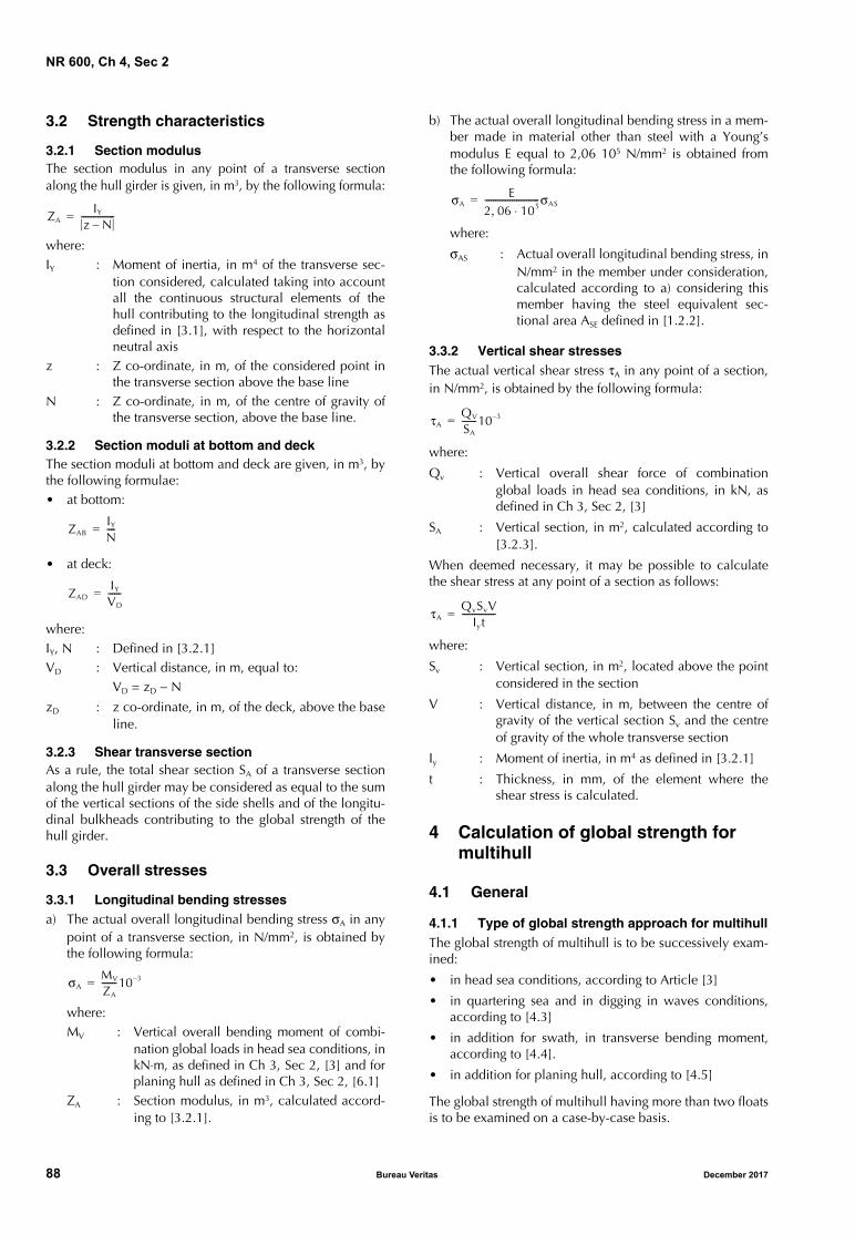
NR 600, Ch 4, Sec 2
3.2 Strength characteristics
3.2.1 Section modulusThe section modulus in any point of a transverse sectionalong the hull girder is given, in m3, by the following formula:
where:IY : Moment of inertia, in m4 of the transverse sec-
tion considered, calculated taking into accountall the continuous structural elements of thehull contributing to the longitudinal strength asdefined in [3.1], with respect to the horizontalneutral axis
z : Z co-ordinate, in m, of the considered point inthe transverse section above the base line
N : Z co-ordinate, in m, of the centre of gravity ofthe transverse section, above the base line.
3.2.2 Section moduli at bottom and deckThe section moduli at bottom and deck are given, in m3, bythe following formulae:• at bottom:
• at deck:
where:IY, N : Defined in [3.2.1]VD : Vertical distance, in m, equal to:
VD = zD − N
zD : z co-ordinate, in m, of the deck, above the baseline.
3.2.3 Shear transverse sectionAs a rule, the total shear section SA of a transverse sectionalong the hull girder may be considered as equal to the sumof the vertical sections of the side shells and of the longitu-dinal bulkheads contributing to the global strength of thehull girder.
3.3 Overall stresses
3.3.1 Longitudinal bending stressesa) The actual overall longitudinal bending stress σA in any
point of a transverse section, in N/mm2, is obtained bythe following formula:
where:MV : Vertical overall bending moment of combi-
nation global loads in head sea conditions, inkN⋅m, as defined in Ch 3, Sec 2, [3] and forplaning hull as defined in Ch 3, Sec 2, [6.1]
ZA : Section modulus, in m3, calculated accord-ing to [3.2.1].
b) The actual overall longitudinal bending stress in a mem-ber made in material other than steel with a Young’smodulus E equal to 2,06 105 N/mm2 is obtained fromthe following formula:
where:
σAS : Actual overall longitudinal bending stress, inN/mm2 in the member under consideration,calculated according to a) considering thismember having the steel equivalent sec-tional area ASE defined in [1.2.2].
3.3.2 Vertical shear stressesThe actual vertical shear stress τA in any point of a section,in N/mm2, is obtained by the following formula:
where:
Qv : Vertical overall shear force of combinationglobal loads in head sea conditions, in kN, asdefined in Ch 3, Sec 2, [3]
SA : Vertical section, in m2, calculated according to[3.2.3].
When deemed necessary, it may be possible to calculatethe shear stress at any point of a section as follows:
where:
Sv : Vertical section, in m2, located above the pointconsidered in the section
V : Vertical distance, in m, between the centre ofgravity of the vertical section Sv and the centreof gravity of the whole transverse section
Iy : Moment of inertia, in m4 as defined in [3.2.1]
t : Thickness, in mm, of the element where theshear stress is calculated.
4 Calculation of global strength for multihull
4.1 General
4.1.1 Type of global strength approach for multihullThe global strength of multihull is to be successively exam-ined:
• in head sea conditions, according to Article [3]
• in quartering sea and in digging in waves conditions,according to [4.3]
• in addition for swath, in transverse bending moment,according to [4.4].
• in addition for planing hull, according to [4.5]
The global strength of multihull having more than two floatsis to be examined on a case-by-case basis.
ZAIY
z N–----------------=
ZABIY
N----=
ZADIY
VD
------=
σAMV
ZA
-------10 3–=
σAE
2 06 105⋅,--------------------------σAS=
τAQV
SA
-------10 3–=
τAQvSvV
Iyt----------------=
88 Bureau Veritas December 2017
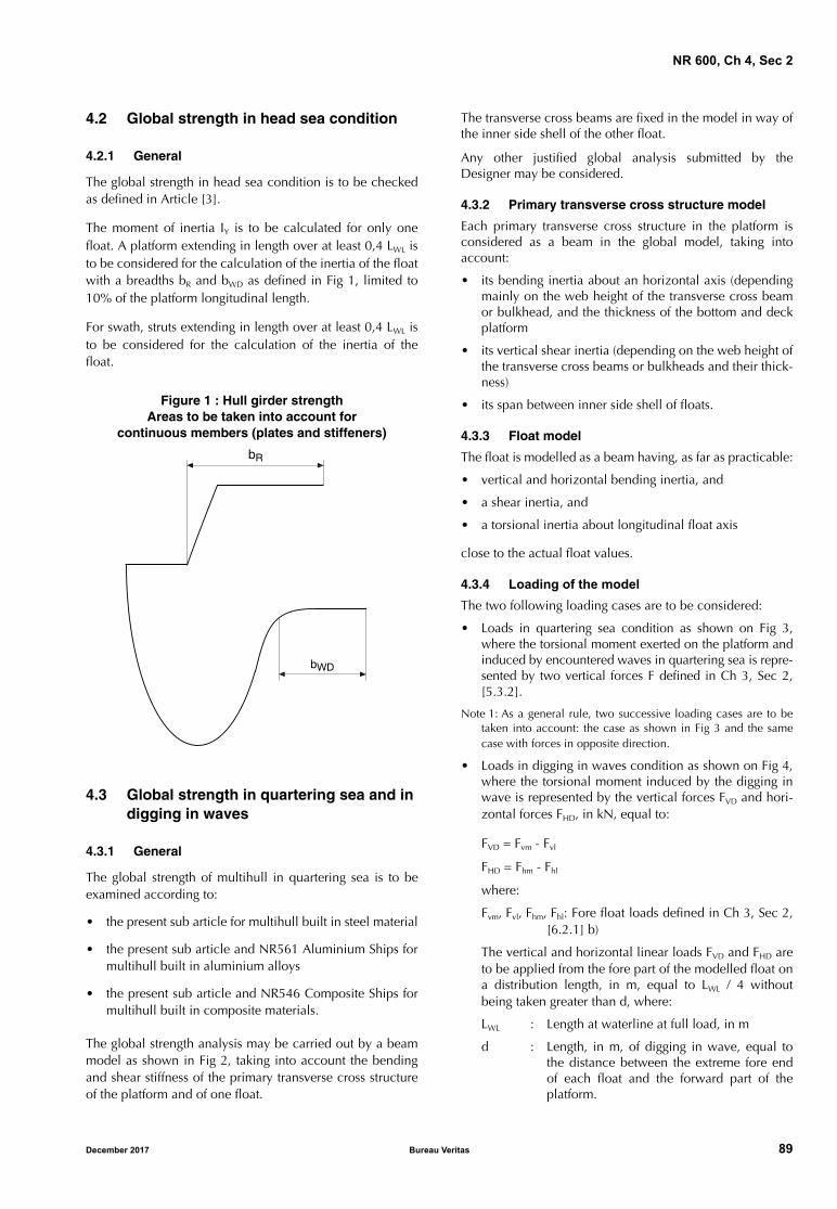
NR 600, Ch 4, Sec 2
4.2 Global strength in head sea condition
4.2.1 General
The global strength in head sea condition is to be checkedas defined in Article [3].
The moment of inertia IY is to be calculated for only onefloat. A platform extending in length over at least 0,4 LWL isto be considered for the calculation of the inertia of the floatwith a breadths bR and bWD as defined in Fig 1, limited to10% of the platform longitudinal length.
For swath, struts extending in length over at least 0,4 LWL isto be considered for the calculation of the inertia of thefloat.
Figure 1 : Hull girder strengthAreas to be taken into account for
continuous members (plates and stiffeners)
4.3 Global strength in quartering sea and in digging in waves
4.3.1 General
The global strength of multihull in quartering sea is to beexamined according to:
• the present sub article for multihull built in steel material
• the present sub article and NR561 Aluminium Ships formultihull built in aluminium alloys
• the present sub article and NR546 Composite Ships formultihull built in composite materials.
The global strength analysis may be carried out by a beammodel as shown in Fig 2, taking into account the bendingand shear stiffness of the primary transverse cross structureof the platform and of one float.
The transverse cross beams are fixed in the model in way ofthe inner side shell of the other float.
Any other justified global analysis submitted by theDesigner may be considered.
4.3.2 Primary transverse cross structure model
Each primary transverse cross structure in the platform isconsidered as a beam in the global model, taking intoaccount:
• its bending inertia about an horizontal axis (dependingmainly on the web height of the transverse cross beamor bulkhead, and the thickness of the bottom and deckplatform
• its vertical shear inertia (depending on the web height ofthe transverse cross beams or bulkheads and their thick-ness)
• its span between inner side shell of floats.
4.3.3 Float model
The float is modelled as a beam having, as far as practicable:
• vertical and horizontal bending inertia, and
• a shear inertia, and
• a torsional inertia about longitudinal float axis
close to the actual float values.
4.3.4 Loading of the model
The two following loading cases are to be considered:
• Loads in quartering sea condition as shown on Fig 3,where the torsional moment exerted on the platform andinduced by encountered waves in quartering sea is repre-sented by two vertical forces F defined in Ch 3, Sec 2,[5.3.2].
Note 1: As a general rule, two successive loading cases are to betaken into account: the case as shown in Fig 3 and the samecase with forces in opposite direction.
• Loads in digging in waves condition as shown on Fig 4,where the torsional moment induced by the digging inwave is represented by the vertical forces FVD and hori-zontal forces FHD, in kN, equal to:
FVD = Fvm - Fvl
FHD = Fhm - Fhl
where:
Fvm, Fvl, Fhm, Fhl: Fore float loads defined in Ch 3, Sec 2,[6.2.1] b)
The vertical and horizontal linear loads FVD and FHD areto be applied from the fore part of the modelled float ona distribution length, in m, equal to LWL / 4 withoutbeing taken greater than d, where:
LWL : Length at waterline at full load, in m
d : Length, in m, of digging in wave, equal tothe distance between the extreme fore endof each float and the forward part of theplatform.
���
��
December 2017 Bureau Veritas 89
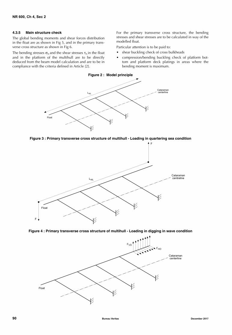
NR 600, Ch 4, Sec 2
4.3.5 Main structure check
The global bending moments and shear forces distributionin the float are as shown in Fig 5, and in the primary trans-verse cross structure as shown in Fig 6.
The bending stresses σA and the shear stresses τA in the floatand in the platform of the multihull are to be directlydeduced from the beam model calculation and are to be incompliance with the criteria defined in Article [2].
For the primary transverse cross structure, the bendingstresses and shear stresses are to be calculated in way of themodelled float.
Particular attention is to be paid to:• shear buckling check of cross bulkheads• compression/bending buckling check of platform bot-
tom and platform deck platings in areas where thebending moment is maximum.
Figure 2 : Model principle
Figure 3 : Primary transverse cross structure of multihull - Loading in quartering sea condition
Figure 4 : Primary transverse cross structure of multihull - Loading in digging in wave condition
CataramancenterlineLWL
Float
CataramancentrelineLWL
Float
F
F
Cataramancenterline
Float
FHD
FVD
90 Bureau Veritas December 2017
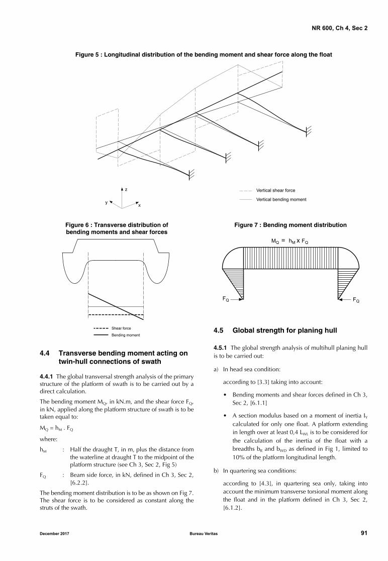
NR 600, Ch 4, Sec 2
Figure 5 : Longitudinal distribution of the bending moment and shear force along the float
Figure 6 : Transverse distribution ofbending moments and shear forces
4.4 Transverse bending moment acting on twin-hull connections of swath
4.4.1 The global transversal strength analysis of the primarystructure of the platform of swath is to be carried out by adirect calculation.
The bending moment MQ, in kN.m, and the shear force FQ,in kN, applied along the platform structure of swath is to betaken equal to:
MQ = hM . FQ
where:
hM : Half the draught T, in m, plus the distance fromthe waterline at draught T to the midpoint of theplatform structure (see Ch 3, Sec 2, Fig 5)
FQ : Beam side force, in kN, defined in Ch 3, Sec 2,[6.2.2].
The bending moment distribution is to be as shown on Fig 7.The shear force is to be considered as constant along thestruts of the swath.
Figure 7 : Bending moment distribution
4.5 Global strength for planing hull
4.5.1 The global strength analysis of multihull planing hullis to be carried out:
a) In head sea condition:
according to [3.3] taking into account:
• Bending moments and shear forces defined in Ch 3,Sec 2, [6.1.1]
• A section modulus based on a moment of inertia IY
calculated for only one float. A platform extendingin length over at least 0,4 LWL is to be considered forthe calculation of the inertia of the float with abreadths bR and bWD as defined in Fig 1, limited to10% of the platform longitudinal length.
b) In quartering sea conditions:
according to [4.3], in quartering sea only, taking intoaccount the minimum transverse torsional moment alongthe float and in the platform defined in Ch 3, Sec 2,[6.1.2].
�������� ���� � ���
�������� ������� � �����
�
�
������� ����
��� � ����
��
�� � �� � ��
��
December 2017 Bureau Veritas 91
NR 600, Ch 4, Sec 3
SECTION 3 LOCAL PLATING SCANTLING
Symbols
k : Material factor, defined in Ch 1, Sec 2, [2] forsteel and in Ch 1, Sec 2, [3] for aluminiumalloys
s : Length, in m, of the shorter side of the platepanel
: Length, in m, of the longer side of the platepanel
μ : Aspect ratio coefficient of the elementary platepanel, equal to:
λ : Corrosion coefficient taken equal to:
• for steel plating:
λ = 1,10
• for aluminium plating:
λ = 1,05
σlocam : Local permissible bending stress, in N/mm2, asdefined in Ch 2, Sec 3, in relation to the type ofload
τlocam : Local permissible shear stress, in N/mm2, asdefined in Ch 2, Sec 3, in relation to the type ofload.
1 General
1.1 General
1.1.1 The local plating scantling is to be carried outaccording to:
• for steel structure: the present Section
• for aluminium structure: the present Section and theNR561 Aluminium Ships
• for composite structure: the present Section and theNR546 Composite Ships.
1.1.2 The scantling of platings contributing to the overalllongitudinal strength of the hull girder and to the overalltransverse strength of transverse cross deck of multihull arealso to be checked as defined in Sec 2.
1.2 Local loads
1.2.1 Local load typesThe local lateral pressures to be considered are:
• for bottom platings: sea pressures, bottom slammingpressures (when slamming may occur for planing hull)and bottom impact pressures on flat bottom forwardarea when applicable
• for side shell and, for multihull, platform bottom plat-ings: sea pressures and side shell impacts
• for deck platings: external or internal loads, minimumloads and, when applicable, wheeled loads
• for all platings, when applicable: internal pressure.
The platings subject to compression local loads are also tobe checked against buckling criteria as defined in Sec 2,[2.3]. In this case, the value of σA considered in Sec 2, [2.3]is to be taken equal to the stress induced in the plate by thelocal loads.
1.2.2 Local load point calculationThe location of the point of the plating where the localloads are to be calculated in order to check the scantlingare defined in:
• Ch 3, Sec 1, [4.1] for steel and aluminium plates
• Ch 3, Sec 1, [4.2] for composite panels
• Ch 3, Sec 1, [4.3] for superstructure panels.
2 Plating scantling
2.1 General
2.1.1 Loading cases and permissible stressesThe scantling of plating is obtained considering successivelythe different loads defined in [1.2.1] sustained by the plate(combined as defined in Ch 3, Sec 1, [3.1] if relevant), andthe associated permissible stresses defined in Ch 2, Sec 3.
2.1.2 Deck plating protected by wood sheathing or deck composition
The thickness of deck plating protected by wood sheathing,deck composition or other arrangements deemed suitableby the Society may be reduced on a case by case basis. Inany case this thickness is to be not less than the minimumvalue defined in [2.2.1].
The sheathing is to be secured to the deck to the satisfactionof the Society.
2.2 Scantling for steel and aluminium plating
2.2.1 Minimum thickness
a) As a rule, the thickness, in mm, of plates calculatedaccording to the present Section are not to be less than:
• for steel plate:
- cargo ship: 0,05 LW k1/2 + 3,5
- non-cargo ship: 0,05 LW k1/2 + 3,0
- sea-going launch and launch: 3,0
μ 1= 21 1 0 33 s--
2
,+, 0 69s-- 1≤,–
92 Bureau Veritas December 2017
NR 600, Ch 4, Sec 3
• for aluminium plate: 0,045 LW1/3 k1/2 + 3
without being taken less than 4 mm or 3 mm forextruded panel,
where:Lw : Lw = 0,5 (LWL + LHULL)
b) Bottom platingAs a rule, the thicknesses of bottom plating are not to belesser than the thickness of side shell.
c) Additional specific minimum thicknesses in relation tothe service notation or service feature assigned to theship are defined in Ch 6, Sec 1.
2.2.2 General casea) As a rule, the thickness of plating subjected to lateral
pressure is to be not less than the value obtained, inmm, from the following formula:
where:p : • local sea pressures or internal pressures,
in kN/m2, as defined in Ch 3, Sec 3 andCh 3, Sec 4, or
• bottom impact pressure for flat bottomforward area, in kN/m2, as defined in Ch3, Sec 3, [3.2], or
• bottom slamming pressure for planinghull, psl, in kN/m2, as defined in Ch 3,Sec 3, [3.3]
np : Coefficient to be taken equal to:• local sea pressures or internal pressures:
- for longitudinally framed steel plating:np = 0,67
- for transversely framed steel plating:np = 0,77
- for steel transverse bulkhead:np = 0,67
- for aluminium plating, whatever theframe system:np = 1,00
• bottom impact pressure for flat bottomforward area and for bottom slammingpressure for planing hull:- for steel plating: np = 0,77
- for aluminium plating: np = 0,85
b) For steel plating, where the thickness t calculatedaccording to item a) is greater than 20 mm, the rulethickness, in mm, may be taken equal to:0,9 t + tc,
where tc is to be taken equal to the sum of the corrosionaddition for each exposed side of the plating as definedin NR467 Steel Ships, Pt B, Ch 4, Sec 2 Tab 2.
c) The thickness of sidescuttles located on the side shellare to be examined according to Ch 5, Sec 1, [7.3], tak-ing into account the value of P defined in the presentrequirement.
2.2.3 Plating of side shell under impact pressureAs a rule, the thickness of side shell plating and of platformbottom plating for multihull subjected to impact pressure isto be not less than the value obtained, in mm, from the fol-lowing formulae:
• if s ≤ 0,6 m
• if s > 0,6 m
where:
p : Pressure, in kN/m2, to be taken equal to:
p = Cp Pssmin
pssmin : Impact pressure on side shell and, for multihull,on platform bottom, in kN/m2, as defined in Ch3, Sec 3, [3.1.2] and/or Ch 3, Sec 3, [3.1.3]
Cp : Pressure coefficient equal to:
Cp = -0,98s2 + 0,3s + 0,95 ≥ 0,8
np : Coefficient to be taken equal to:
• for steel plating: np = 0,77
• for aluminium plating: np = 0,85
ssi : Length, in m, equal to:
ssi = 0,6 (1 + s) ≤
The thickness of sidescuttles located on the side shell andsubmitted to side shell impact are to be examined accord-ing to Ch 5, Sec 1, [7.3], taking into account the valueof Pssmin defined in the present requirement where applica-ble (see Ch 3, Sec 3, [3.1]).
2.2.4 Plating subjected to wheeled loadsThe thickness of plate panels subjected to wheeled loads isto be not less than the value obtained, in mm, from the fol-lowing formula:
a) Single wheel or group of wheels:
where:
k : Material factor, defined in Ch 1, Sec 2, [2]for steel and in Ch 1, Sec 2, [3] for alumin-ium alloys
n : Number of wheels on the plate panel:
• 1 in the case of single wheel
• the number of wheels in a group ofwheels in the case of double or triplewheels
Cm : Coefficient equal to:
• 1,00 for steel
• 1,55 for aluminium alloy
CWL : Coefficient to be taken equal to:
t 22 4, λnpμs pσlocam
--------------=
t 17 3 1ssi
-------λnpμs pσlocam
--------------,=
t 13 4 1 5s2, 0 18,–ssis
---------------------------------λnpμ pσlocam
--------------,=
t 0 9, CmCWLλ FWnk=
CWL 2 15, 0 05s--,– 0 02 4
s--–
α0 5,, 1 75α0 25,,–+=
December 2017 Bureau Veritas 93
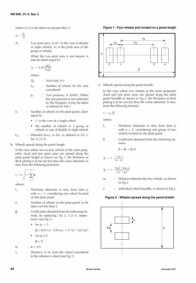
NR 600, Ch 4, Sec 3
where /s is to be taken not greater than 3
AT : Tyre print area, in m2. In the case of doubleor triple wheels, AT is the print area of thegroup of wheels.
When the tyre print area is not known, itmay be taken equal to:
where:
QA : Axle load, in t
nW : Number of wheels for the axleconsidered
pT : Tyre pressure, in kN/m2. Whenthe tyre pressure is not indicatedby the Designer, it may be takenas defined in Tab 1
n : Number of wheels on the plate panel, takenequal to:
• 1 in the case of a single wheel
• the number of wheels in a group ofwheels in case of double or triple wheels
FW : Wheeled force, in kN, as defined in Ch 3,Sec 4, [3.3].
b) Wheels spread along the panel length:
In the case where two to four wheels of the same prop-erties (load and tyre print area) are spread along theplate panel length as shown on Fig 1, the thickness ofdeck plating is to be not less than the value obtained, inmm, from the following formulae:
where:
t1 : Thickness obtained, in mm, from item a)with n = 1, considering one wheel locatedon the plate panel
n : Number of wheels on the plate panel, to betaken not less than 2
βi : Coefficients obtained from the following for-mula, by replacing i by 2, 3 or 4, respec-tively (see Fig 1):
• for αi < 2:
βi = 0,8 (1,2 − 2,02 αi + 1,17 αi2 − 0,23 αi
3)
• for αi ≥ 2:
βi = 0
αi : αi = xi/s
xi : Distance, in m, from the wheel consideredto the reference wheel (see Fig 1)
Figure 1 : Four wheels axle located on a panel length
c) Wheels spread along the panel breath:
In the case where two wheels of the same properties(load and tyre print area) are spread along the platepanel breadth as shown in Fig 2, the thickness of deckplating is to be not less than the value obtained, in mm,from the following formula:
where:
t2 : Thickness obtained, in mm, from item a)with n = 2, considering one group of twowheels located on the plate panel
δ : Coefficient obtained from the following for-mula:
δ = (δ1 + δ2)/2
ws : Distance between the two wheels, as shownin Fig 2
v : Individual wheel breadth, as shown in Fig 2.
Figure 2 : Wheels spread along the panel breath
α AT
s------=
AT 9 81nQA
nWpT
-------------,=
t t1 1 βi
i 2=
n
+=
X2 X3
X4
2 1 3 4
s
t t2 δ=
δ1 1ws
s v–----------- –=
δ2 13ws
2 6wsv+3s2 4v2–------------------------------–=
s
v
Ws
94 Bureau Veritas December 2017
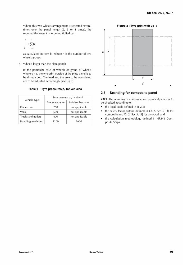
NR 600, Ch 4, Sec 3
Where this two-wheels arrangement is repeated severaltimes over the panel length (2, 3 or 4 times), therequired thickness t is to be multiplied by:
as calculated in item b), where n is the number of twowheels groups.
d) Wheels larger than the plate panel:
In the particular case of wheels or group of wheelswhere u > s, the tyre print outside of the plate panel is tobe disregarded. The load and the area to be consideredare to be adjusted accordingly (see Fig 3).
Table 1 : Tyre pressures pT for vehicles
Figure 3 : Tyre print with u > s
2.3 Scantling for composite panel
2.3.1 The scantling of composite and plywood panels is tobe checked according to: • the local loads defined in [1.2.1]• the safety factor criteria defined in Ch 2, Sec 3, [3] for
composite and Ch 2, Sec 3, [4] for plywood, and• the calculation methodology defined in NR546 Com-
posite Ships.
Vehicle typeTyre pressure pT, in kN/m2
Pneumatic tyres Solid rubber tyres
Private cars 250 not applicable
Vans 600 not applicable
Trucks and trailers 800 not applicable
Handling machines 1100 1600
1 βi
i 2=
n
+
s
�
v
u
December 2017 Bureau Veritas 95
NR 600, Ch 4, Sec 4
SECTION 4 LOCAL SECONDARY STIFFENER SCANTLING
Symbols
s : Spacing, in m, of the secondary stiffener underconsideration
: Span, in m, of the secondary stiffener underconsideration
k : Material factor, defined in Ch 1, Sec 2
σlocam : Local permissible bending stress, in N/mm2, asdefined in Ch 2, Sec 3, in relation to the type ofload
τlocam : Local permissible shear stress, in N/mm2, asdefined in Ch 2, Sec 3, in relation to the type ofload
m : End stiffener condition coefficient, defined in [1.4]
λ : Corrosion coefficient to be taken equal to:
• steel structure:
- for stiffener located in a dry compartment:
λ = 1,1
- for stiffener located in a liquid compart-ment:
λ = 1,2
• aluminium structure:
λ = 1,05.
1 General
1.1 Local scantling
1.1.1 GeneralThe local secondary stiffener scantling is to be carried outaccording to:
• for steel structure: the present Section
• for aluminium structure: the present Section and NR561Aluminium Ships
• for composite structure: the present Section and NR546Composite Ships.
1.1.2 The scantling of secondary stiffeners contributing tothe overall longitudinal strength of the hull girder and to theoverall transverse strength of platform of multihull are alsoto be checked as defined in Sec 2.
1.2 Local loads
1.2.1 Local load typesThe local lateral pressures to be considered are:
• for bottom secondary stiffeners: sea pressures, bottomslamming pressures (when slamming may occur forplaning hull) and bottom impact pressures on flat bot-tom forward area when applicable
• for side shell and, for multihull, platform bottom sec-ondary stiffeners: sea pressures and side shell impacts
• for deck secondary stiffeners: external or internal loads,minimum loads, and when applicable, wheeled loads
• for all stiffeners, when applicable: internal pressures.
The secondary stiffeners and their attached platings sub-jected to compression local loads are also to be checkedagainst buckling criteria as defined in Sec 2, [2.3]. In thiscase, the value of σA considered in Sec 2, [2.3] is to betaken equal to the stress induced in the stiffener and itsassociated plate by the local loads.
1.2.2 Local load point calculation
The location of the point of the stiffener where the localloads are to be calculated in order to check the scantlingare defined in Ch 3, Sec 1, [4].
1.3 Section modulus calculation
1.3.1 General case and attached plating width
As a rule, the inertia, section modulus and shear section of sec-ondary stiffeners are to be determined by direct calculation.
The width bp , in m, of the attached plating to be taken intoaccount for the inertia and section modulus calculations areto be taken equal to the spacing between stiffeners, or halfthe spacing between stiffeners when the plating extends onone side only.
1.3.2 Bulb section for steel stiffeners
As a rule, the inertia, section modulus and shear section ofbulb section of steel stiffener may to be determined takinginto account the following equivalent dimensions of anangle profile:
where:
h’w, t’w : Height and thickness of the bulb section, in
mm, as shown in Fig 1
α : Coefficient equal to:
hw hw′ hw
′
9 2,-------- 2+–=
tw tw′=
bf α tw′ hw
′
6 7,-------- 2–+=
tfhw
′
9 2,-------- 2–=
1 1, 120 hw′–( )2
3000-----------------------------+ for hw
′ 120≤
1 0, for hw′ 120>
96 Bureau Veritas December 2017
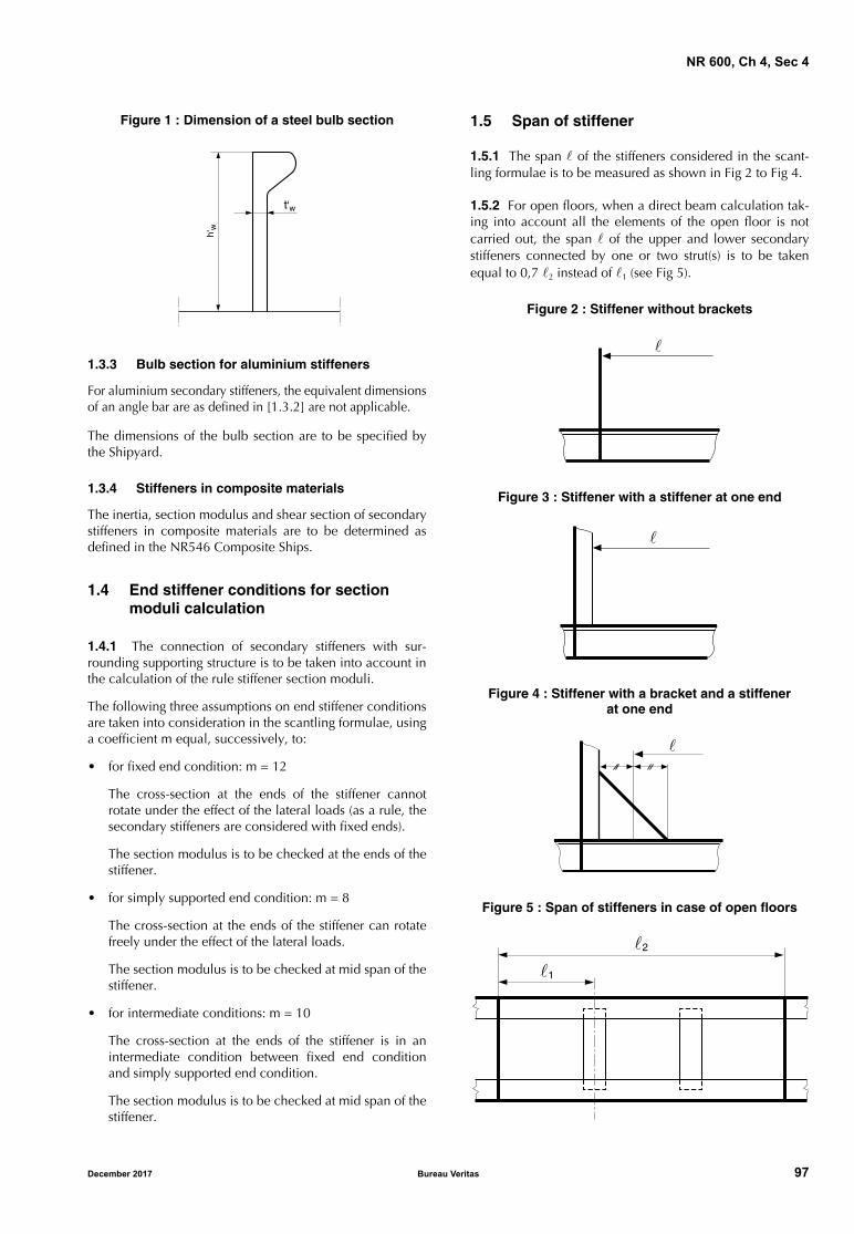
NR 600, Ch 4, Sec 4
Figure 1 : Dimension of a steel bulb section
1.3.3 Bulb section for aluminium stiffeners
For aluminium secondary stiffeners, the equivalent dimensionsof an angle bar are as defined in [1.3.2] are not applicable.
The dimensions of the bulb section are to be specified bythe Shipyard.
1.3.4 Stiffeners in composite materials
The inertia, section modulus and shear section of secondarystiffeners in composite materials are to be determined asdefined in the NR546 Composite Ships.
1.4 End stiffener conditions for section moduli calculation
1.4.1 The connection of secondary stiffeners with sur-rounding supporting structure is to be taken into account inthe calculation of the rule stiffener section moduli.
The following three assumptions on end stiffener conditionsare taken into consideration in the scantling formulae, usinga coefficient m equal, successively, to:
• for fixed end condition: m = 12
The cross-section at the ends of the stiffener cannotrotate under the effect of the lateral loads (as a rule, thesecondary stiffeners are considered with fixed ends).
The section modulus is to be checked at the ends of thestiffener.
• for simply supported end condition: m = 8
The cross-section at the ends of the stiffener can rotatefreely under the effect of the lateral loads.
The section modulus is to be checked at mid span of thestiffener.
• for intermediate conditions: m = 10
The cross-section at the ends of the stiffener is in anintermediate condition between fixed end conditionand simply supported end condition.
The section modulus is to be checked at mid span of thestiffener.
1.5 Span of stiffener
1.5.1 The span of the stiffeners considered in the scant-ling formulae is to be measured as shown in Fig 2 to Fig 4.
1.5.2 For open floors, when a direct beam calculation tak-ing into account all the elements of the open floor is notcarried out, the span of the upper and lower secondarystiffeners connected by one or two strut(s) is to be takenequal to 0,7 2 instead of 1 (see Fig 5).
Figure 2 : Stiffener without brackets
Figure 3 : Stiffener with a stiffener at one end
Figure 4 : Stiffener with a bracket and a stiffenerat one end
Figure 5 : Span of stiffeners in case of open floors
����� �
�
�
�
�1
�2
December 2017 Bureau Veritas 97
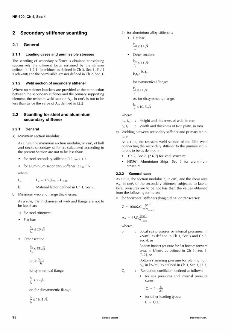
NR 600, Ch 4, Sec 4
2 Secondary stiffener scantling
2.1 General
2.1.1 Loading cases and permissible stresses
The scantling of secondary stiffener is obtained consideringsuccessively the different loads sustained by the stiffenerdefined in [1.2.1] (combined as defined in Ch 3, Sec 1, [3.1]if relevant) and the permissible stresses defined in Ch 2, Sec 3.
2.1.2 Weld section of secondary stiffener
Where no stiffener brackets are provided at the connectionbetween the secondary stiffener and the primary supportingelement, the resistant weld section Aw, in cm2, is not to beless than twice the value of Ash defined in [2.2].
2.2 Scantling for steel and aluminium secondary stiffener
2.2.1 General
a) Minimum section modulus:
As a rule, the minimum section modulus, in cm3, of hulland decks secondary stiffeners calculated according tothe present Section are not to be less than:
• for steel secondary stiffener: 0,2 LW k + 4
• for aluminium secondary stiffener: 2 LW1/3 k
where:
Lw : Lw = 0,5 (LWL + LHULL)
k : Material factor defined in Ch 1, Sec 2.
b) Minimum web and flange thicknesses:
As a rule, the thicknesses of web and flange are not tobe less than:
1) for steel stiffeners:
• Flat bar:
• Other section:
for symmetrical flange:
or, for dissymmetric flange:
2) for aluminium alloy stiffeners:
• Flat bar:
• Other section:
for symmetrical flange:
or, for dissymmetric flange:
where:
hw, tw : Height and thickness of web, in mm
bf, tf : Width and thickness of face plate, in mm
c) Welding between secondary stiffener and primary struc-ture:
As a rule, the resistant weld section of the fillet weldconnecting the secondary stiffener to the primary struc-ture is to be as defined in:
• Ch 7, Sec 2, [2.6.7] for steel structure
• NR561 Aluminium Ships, Sec 3 for aluminiumstructure.
2.2.2 General caseAs a rule, the section modulus Z, in cm3, and the shear areaAsh, in cm2, of the secondary stiffeners subjected to laterallocal pressures are to be not less than the values obtainedfrom the following formulae:
• for horizontal stiffeners (longitudinal or transverse):
where:
p : Local sea pressures or internal pressures, inkN/m2, as defined in Ch 3, Sec 3 and Ch 3,Sec 4, or
Bottom impact pressure for flat bottom forwardarea, in kN/m2, as defined in Ch 3, Sec 3,[3.2], or
Bottom slamming pressure for planing hull,psl, in kN/m2, as defined in Ch 3, Sec 3, [3.3]
Ct : Reduction coefficient defined as follows:
• for sea pressures and internal pressurecases:
• for other loading types:
Ct = 1,00
hw
tw
------ 20 k≤
hw
tw
------ 55 k≤
bftfhwtw
6-----------≥
bf
tf
---- 33 k≤
bf
tf
---- 16 5 k,≤
hw
tw
------ 15 k≤
hw
tw
------ 33 k≤
bftfhwtw
6-----------≥
bf
tf
---- 21 k≤
bf
tf
---- 10 5 k,≤
Z 1000λCtps2
mσlocam
-------------------=
Ash 5λCtps
τlocam
-------------=
Ct 1 s2------–=
98 Bureau Veritas December 2017
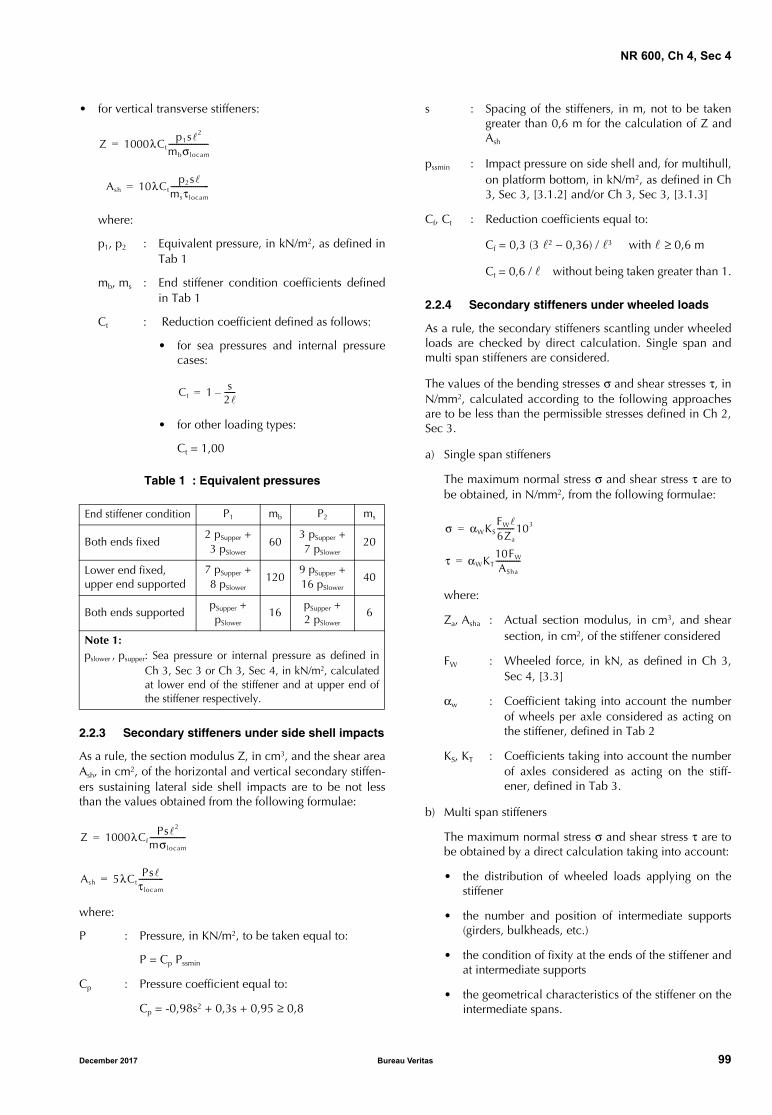
NR 600, Ch 4, Sec 4
• for vertical transverse stiffeners:
where:
p1, p2 : Equivalent pressure, in kN/m2, as defined inTab 1
mb, ms : End stiffener condition coefficients definedin Tab 1
Ct : Reduction coefficient defined as follows:
• for sea pressures and internal pressurecases:
• for other loading types:
Ct = 1,00
Table 1 : Equivalent pressures
2.2.3 Secondary stiffeners under side shell impacts
As a rule, the section modulus Z, in cm3, and the shear areaAsh, in cm2, of the horizontal and vertical secondary stiffen-ers sustaining lateral side shell impacts are to be not lessthan the values obtained from the following formulae:
where:
P : Pressure, in KN/m2, to be taken equal to:
P = Cp Pssmin
Cp : Pressure coefficient equal to:
Cp = -0,98s2 + 0,3s + 0,95 ≥ 0,8
s : Spacing of the stiffeners, in m, not to be takengreater than 0,6 m for the calculation of Z andAsh
pssmin : Impact pressure on side shell and, for multihull,on platform bottom, in kN/m2, as defined in Ch3, Sec 3, [3.1.2] and/or Ch 3, Sec 3, [3.1.3]
Cf, Ct : Reduction coefficients equal to:
Cf = 0,3 (3 2 − 0,36) / 3 with ≥ 0,6 m
Ct = 0,6 / without being taken greater than 1.
2.2.4 Secondary stiffeners under wheeled loads
As a rule, the secondary stiffeners scantling under wheeledloads are checked by direct calculation. Single span andmulti span stiffeners are considered.
The values of the bending stresses σ and shear stresses τ, inN/mm2, calculated according to the following approachesare to be less than the permissible stresses defined in Ch 2,Sec 3.
a) Single span stiffeners
The maximum normal stress σ and shear stress τ are tobe obtained, in N/mm2, from the following formulae:
where:
Za, Asha : Actual section modulus, in cm3, and shearsection, in cm2, of the stiffener considered
FW : Wheeled force, in kN, as defined in Ch 3,Sec 4, [3.3]
αw : Coefficient taking into account the numberof wheels per axle considered as acting onthe stiffener, defined in Tab 2
KS, KT : Coefficients taking into account the numberof axles considered as acting on the stiff-ener, defined in Tab 3.
b) Multi span stiffeners
The maximum normal stress σ and shear stress τ are tobe obtained by a direct calculation taking into account:
• the distribution of wheeled loads applying on thestiffener
• the number and position of intermediate supports(girders, bulkheads, etc.)
• the condition of fixity at the ends of the stiffener andat intermediate supports
• the geometrical characteristics of the stiffener on theintermediate spans.
End stiffener condition P1 mb P2 ms
Both ends fixed2 pSupper +3 pSlower
603 pSupper +7 pSlower
20
Lower end fixed, upper end supported
7 pSupper +8 pSlower
1209 pSupper +16 pSlower
40
Both ends supportedpSupper +pSlower
16pSupper +2 pSlower
6
Note 1:pslower , psupper: Sea pressure or internal pressure as defined in
Ch 3, Sec 3 or Ch 3, Sec 4, in kN/m2, calculatedat lower end of the stiffener and at upper end ofthe stiffener respectively.
Z 1000λCtp1s2
mbσlocam
---------------------=
Ash 10λCtp2s
msτlocam
--------------------=
Ct 1 s2------–=
Z 1000λCfPs2
mσlocam
-------------------=
Ash 5λCtPs
τlocam
-------------=
σ αWKSFW
6Za
---------103=
τ αWKT10FW
ASha
-------------=
December 2017 Bureau Veritas 99
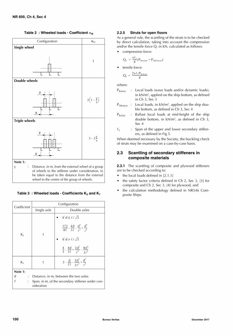
NR 600, Ch 4, Sec 4
Table 2 : Wheeled loads - Coefficient αW
Table 3 : Wheeled loads - Coefficients KS and KT
2.2.5 Struts for open floorsAs a general rule, the scantling of the struts is to be checkedby direct calculation, taking into account the compressionand/or the tensile force Q, in kN, calculated as follows:• compression force:
• tensile force:
where:PBottom : Local loads (wave loads and/or dynamic loads),
in kN/m2, applied on the ship bottom, as definedin Ch 3, Sec 3
PDBottom : Local loads, in kN/m2, applied on the ship dou-ble bottom, as defined in Ch 3, Sec 4
PBallast : Ballast local loads at mid-height of the shipdouble bottom, in kN/m2, as defined in Ch 3,Sec 4
2 : Span of the upper and lower secondary stiffen-ers, as defined in Fig 5.
When deemed necessary by the Society, the buckling checkof struts may be examined on a case-by-case basis.
2.3 Scantling of secondary stiffeners in composite materials
2.3.1 The scantling of composite and plywood stiffenersare to be checked according to: • the local loads defined in [2.1.1]• the safety factor criteria defined in Ch 2, Sec 3, [3] for
composite and Ch 2, Sec 3, [4] for plywood, and• the calculation methodology defined in NR546 Com-
posite Ships.
Configuration αW
Single wheel
1
Double wheels
Triple wheels
Note 1:y : Distance, in m, from the external wheel of a group
of wheels to the stiffener under consideration, tobe taken equal to the distance from the externalwheel to the centre of the group of wheels.
CoefficientConfiguration
Single axle Double axles
KS 1
•
•
KT 1
Note 1:d : Distance, in m, between the two axles : Span, in m, of the secondary stiffener under con-
sideration
y
s
2 1 ys---–
s
y
3 2ys---–
if d 3⁄≤
17281---------- 4d
3-------– d2
2-----– d4
4-----+
if d 3⁄>
43--- 4d
3-------– 3d2
2
--------- 8d3
33---------–+
2 d2------– 3d2
22---------– d3
3-----+
Qcs2
4------- PBottom PDBottom+( )=
Qt2s2PBallast
4---------------------------=
100 Bureau Veritas December 2017
NR 600, Ch 4, Sec 5
SECTION 5 LOCAL PRIMARY STIFFENER SCANTLING
Symbols
σVM : Von Mises equivalent stress, obtained from thefollowing formula:
σ : Normal stress in the direction of the beam axis,induced by local loads
τ : Shear stress in the direction of the local loadsapplied to the beam
λ : Corrosion coefficient taken equal to:
• for steel structure:
λ = 1,10
• for aluminium structure:
λ = 1,05
1 General
1.1 Local scantling
1.1.1 The local primary stiffener scantling is to be carriedout according to:
• for steel structure: the present Section
• for aluminium structure:
the present Section and NR561 Aluminium Ships
• for composite structure:
the present Section and NR546 Composite Ships.
1.1.2 The scantling of primary stiffeners contributing to theoverall longitudinal strength of the hull girder and to theoverall transverse strength of platform of multihull are alsoto be checked as defined in Sec 2.
1.2 Structural beam models
1.2.1 Isolated beam model
a) The requirements for the scantling of primary stiffenersdefined in the present Section apply for isolated beamcalculation.
b) Local loads
The local lateral pressures to be considered are definedin [1.2.2], b).
c) Local load point calculation
The location of the point of the stiffener where the localloads are to be calculated in order to check the scant-ling are defined in Ch 3, Sec 1, [4].
d) The scantling of primary stiffeners and their attachedplatings subjected to compression local loads are also tobe checked against buckling criteria as defined in Sec 2,[2.3]. In this case, the value of σA considered in Sec 2,[2.3] is to be taken equal to the stress induced in thestiffener and its associated plate by the local loads.
e) Checking criteria
The bending stresses, shear stresses and combinedstresses calculated by the model are to be in accordancewith the permissible values defined in Ch 2, Sec 3.
1.2.2 Two- or three-dimensional beam model
When an isolated beam calculation of the primary structureis not possible due to an interaction of the primary stiffen-ers, a two- or three-dimensional structural model analysisincluding the different primary stiffeners is to be carried outas follows:
a) Model:
The structural model is to represent the primary support-ing members, with their attached plating (as defined in[1.4.1]), of the structure area considered.
The extension of the structural model is to be such thatthe results in the areas to be analysed are not influencedby the unavoidable inaccuracy in the modelling of theboundary conditions.
b) Loading conditions:
The local lateral pressures to be considered are:
• for bottom primary stiffeners: sea pressures and bot-tom slamming pressures (when slamming mayoccur)
• for side shell and, for multihull, primary transversecross structure of platform bottom: sea pressures(without taking into account side shell impact)
• for deck primary stiffeners: external or internal pres-sures, minimum loads and, when applicable,wheeled loads
• for all primary stiffeners, when applicable: internalpressures.
When deemed necessary, it may be taken into accountof the counteraction between the internal and externalloads in the most severe conditions (see Ch 3, Sec 1,[3.1.1]).
Note 1: When a bottom slamming pressure analysis is carried outfor planing hull, the impact pressure psl defined in Ch 3, Sec 3,[3.3.2] is to be only applied on one floor of the model as a con-stant pressure. The other floors of the model are to be loadedby the bottom sea pressure defined in Ch 3, Sec 3, [2.2.1].
σVM σ 3τ+=
December 2017 Bureau Veritas 101
NR 600, Ch 4, Sec 5
c) Local load point calculation:
The location of the point of the stiffener where the localloads are to be calculated in order to check the scant-ling are defined in Ch 3, Sec 1, [4].
d) Checking criteria:
It is to be checked that the equivalent stresses σVM
deduced from the model are in compliance with Ch 2,Sec 3.
1.2.3 Curved beam model
The curvature of primary supporting members may be takeninto account by direct analysis.
In case of two dimensional or three dimensional beamstructural model, the curved primary supporting membersmay be represented by a number N of straight beams, Nbeing adequately selected to minimize the spring effect inway of knuckles.
The stiffness of knuckle equivalent springs is considered asminor from the point of view of the local bending momentand the shear force distribution when the angle betweentwo successive beams is not more than 3°.
1.3 Finite element model
1.3.1 General
When the analysis of primary stiffener structure is carriedout by a finite element model, the model is to be submittedto the Society for examination.
As a rule, one of the procedure defined in NR467 SteelShips, Pt B, Ch 7, App 1 is to be adopted for the finite ele-ment model.
It is to be checked that the equivalent stresses σVM deducedfrom the finite element model calculation are in accordancewith the permissible stresses defined in Ch 2, Sec 3.
1.4 Beam section modulus calculation
1.4.1 Attached plating
As a rule, the inertia, section modulus and shear section ofprimary stiffeners are to be determined by direct calcula-tion.
The width bp, in m, of the attached plating to take intoaccount for the inertia and section modulus calculations areto be taken equal to the spacing between primary stiffeners(or half of the spacing between primary stiffeners when theplating extends on one side only), without being takengreater than 0,2 (or 0,1 when the plating extends on oneside only), where is the length of the primary stiffener.
1.5 End stiffener conditions for calculation
1.5.1 Definition and calculation conditions
The assumptions on end stiffener conditions for the calcula-tion of section moduli of primary stiffeners are defined inSec 4, [1.4.1].
As a rule, the coefficient m is to be taken equal to 10 for anisolated beam calculation of primary stiffener.
2 Primary stiffener scantling analysed by isolated beam calculation under local loads
2.1 Scantling for steel and aluminium pri-mary stiffeners under lateral loads
2.1.1 ScantlingThe primary stiffener scantling is to be carried out asdefined for the secondary stiffener scantling in Sec 4,excepted otherwise specified, considering successively thedifferent loads sustained by the primary stiffener defined in[1.2.1], item b) and the relevant permissible stresses definedin Ch 2, Sec 3.
The following parameters are to be taken into account inthe section modulus and shear area formulae:
• Reduction coefficient Ct = 1
• Corrosion coefficient λ as defined in the present Section
The minimum section modulus for secondary stiffenersdefined in Sec 4, [2.2.1] is not applicable to primary stiffen-ers.
2.1.2 Additional check of primary stiffenersIn addition to [2.1.1], the primary stiffeners are also to beexamined taking into account the following requirements:
a) Buckling of attached plating:
Depending on the compression stress level in theattached plating induced by the bending of primary stiff-ener under the local loading cases, it may be necessaryto check the buckling of the attached plating along theprimary stiffener span.
The buckling of the attached plating is to be checkedaccording to the criteria defined in Ch 2, Sec 3.
b) Minimum web thickness:
As a rule, the thickness of the web, in mm, for steel andaluminium structure is to be not less than:
• general case:
where:
Lw : Lw = 0,5 (Lwl + LHULL)
• floors and bottom longitudinal girders:
As defined in Tab 1
Additional specific minimum thicknesses of webs in rela-tion to the service notation or service feature assigned to theship are defined in Ch 6, Sec 1.
2.2 Scantling for steel and aluminium pri-mary stiffeners under wheeled loads
2.2.1 Wheeled loadsFor primary supporting members subjected to wheeledloads, the section modulus and shear area may be calcu-lated as defined for secondary stiffener in Sec 4, [2.2.2],considering the distribution of the wheeled loads as an uni-form pressures p.
t 1 2 3 7, 0 015LW,+( ),=
102 Bureau Veritas December 2017
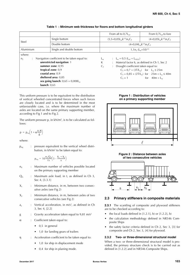
NR 600, Ch 4, Sec 5
Table 1 : Minimum web thickness for floors and bottom longitudinal girders
This uniform pressure is to be equivalent to the distributionof vertical wheeled concentrated forces when such forcesare closely located and is to be determined in the mostunfavourable case, i.e. where the maximum number ofaxles are located on the same primary supporting member,according to Fig 1 and to Fig 2.
The uniform pressure p, in kN/m2, is to be calculated as fol-lows:
where:
peq : pressure equivalent to the vertical wheel distri-bution, in kN/m2 to be taken equal to:
nV : Maximum number of vehicles possible locatedon the primary supporting member
QA : Maximum axle load, in t, as defined in Ch 3,Sec 4, [3.3.1]
X1 : Minimum distance, in m, between two consec-utive axles (see Fig 2)
X2 : Minimum distance, in m, between axles of twoconsecutive vehicles (see Fig 2)
az : Vertical acceleration, in m/s2, as defined in Ch3, Sec 4, [2.2]
g : Gravity acceleration taken equal to 9,81 m/s2
α : Coefficient taken equal to:
• 0,5 in general
• 1,0 for landing gears of trailers
η : Acceleration coefficient to be taken equal to:
• 1,0 for ship in displacement mode
• 0,4 for ship in planing mode.
Figure 1 : Distribution of vehicles on a primary supporting member
Figure 2 : Distance between axles of two consecutive vehicles
2.3 Primary stiffeners in composite materials
2.3.1 The scantling of composite and plywood stiffenersare to be checked according to:
• the local loads defined in [1.2.1], b) or [1.2.2], b)
• the calculation methodology defined in NR546 Com-posite Ships
• the safety factor criteria defined in Ch 2, Sec 3, [3] forcomposite and Ch 2, Sec 3, [4] for plywood.
2.3.2 Two- or three-dimensional structural model
When a two- or three-dimensional structural model is pro-vided, the primary structure check is to be carried out asdefined in [1.2.2] and in NR546 Composite Ships.
From aft to 0,7Lwl From 0,7Lwl to fore
SteelSingle bottom (5,5+0,05Lwk1/2)n2CT (4+0,05Lwk1/2)n2CT
Double bottom (4+0,04Lwk1/2)n2CT
Aluminium Single and double bottom 1,1n2 (Lw+10)1/2
where:n2 : Navigation coefficient to be taken equal to:
unrestricted navigation: 1summer zone: 0,95tropical zone: 0,9coastal area: 0,9sheltered area: 0,85sea going launch: 0,65 + 0,008Lw
launch: 0,65
Lw : Lw = 0,5 (Lwl + LHULL)K : Material factor k, as defined in Ch 1, Sec 2CT : Draught coefficient taken equal to:
CT = 0,7 + (3T/Lw) for Lw ≤ 25mCT = 0,85 + (2T/Lw) for 25m < Lw ≤ 40mCT = 1 for 40m < Lw
p peq 1 αazηg---------+
=
peq 10nVQA
s-------------- 3
X1 X2+s
------------------– =
�
X1 X2S
December 2017 Bureau Veritas 103
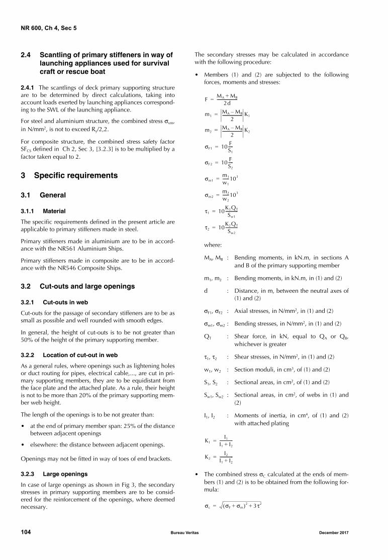
NR 600, Ch 4, Sec 5
2.4 Scantling of primary stiffeners in way of launching appliances used for survival craft or rescue boat
2.4.1 The scantlings of deck primary supporting structureare to be determined by direct calculations, taking intoaccount loads exerted by launching appliances correspond-ing to the SWL of the launching appliance.
For steel and aluminium structure, the combined stress σvm,in N/mm2, is not to exceed Ry/2,2.
For composite structure, the combined stress safety factorSFCS defined in Ch 2, Sec 3, [3.2.3] is to be multiplied by afactor taken equal to 2.
3 Specific requirements
3.1 General
3.1.1 Material
The specific requirements defined in the present article areapplicable to primary stiffeners made in steel.
Primary stiffeners made in aluminium are to be in accord-ance with the NR561 Aluminium Ships.
Primary stiffeners made in composite are to be in accord-ance with the NR546 Composite Ships.
3.2 Cut-outs and large openings
3.2.1 Cut-outs in web
Cut-outs for the passage of secondary stiffeners are to be assmall as possible and well rounded with smooth edges.
In general, the height of cut-outs is to be not greater than50% of the height of the primary supporting member.
3.2.2 Location of cut-out in web
As a general rules, where openings such as lightening holesor duct routing for pipes, electrical cable,..., are cut in pri-mary supporting members, they are to be equidistant fromthe face plate and the attached plate. As a rule, their heightis not to be more than 20% of the primary supporting mem-ber web height.
The length of the openings is to be not greater than:
• at the end of primary member span: 25% of the distancebetween adjacent openings
• elsewhere: the distance between adjacent openings.
Openings may not be fitted in way of toes of end brackets.
3.2.3 Large openings
In case of large openings as shown in Fig 3, the secondarystresses in primary supporting members are to be consid-ered for the reinforcement of the openings, where deemednecessary.
The secondary stresses may be calculated in accordancewith the following procedure:
• Members (1) and (2) are subjected to the followingforces, moments and stresses:
where:
MA, MB : Bending moments, in kN.m, in sections Aand B of the primary supporting member
m1, m2 : Bending moments, in kN.m, in (1) and (2)
d : Distance, in m, between the neutral axes of(1) and (2)
σF1, σF2 : Axial stresses, in N/mm2, in (1) and (2)
σm1, σm2 : Bending stresses, in N/mm2, in (1) and (2)
QT : Shear force, in kN, equal to QA or QB,whichever is greater
τ1, τ2 : Shear stresses, in N/mm2, in (1) and (2)
w1, w2 : Section moduli, in cm3, of (1) and (2)
S1, S2 : Sectional areas, in cm2, of (1) and (2)
Sw1, Sw2 : Sectional areas, in cm2, of webs in (1) and(2)
I1, I2 : Moments of inertia, in cm4, of (1) and (2)with attached plating
• The combined stress σC calculated at the ends of mem-bers (1) and (2) is to be obtained from the following for-mula:
FMA MB+
2d----------------------=
m1MA MB–
2--------------------- K1=
m2MA MB–
2--------------------- K2=
σF1 10 FS1
-----=
σF2 10 FS2
-----=
σm1m1
w1
-------103=
σm2m2
w2
-------103=
τ1 10K1QT
Sw1
-------------=
τ2 10K2QT
Sw2
-------------=
K1I1
I1 I2+--------------=
K2I2
I1 I2+--------------=
σc σF σm+( )2 3τ2+=
104 Bureau Veritas December 2017
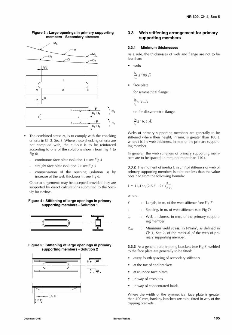
NR 600, Ch 4, Sec 5
Figure 3 : Large openings in primary supporting members - Secondary stresses
• The combined stress σC is to comply with the checkingcriteria in Ch 2, Sec 3. Where these checking criteria arenot complied with, the cut-out is to be reinforcedaccording to one of the solutions shown from Fig 4 toFig 6:
- continuous face plate (solution 1): see Fig 4
- straight face plate (solution 2): see Fig 5
- compensation of the opening (solution 3) byincrease of the web thickness t1: see Fig 6.
Other arrangements may be accepted provided they aresupported by direct calculations submitted to the Soci-ety for review.
Figure 4 : Stiffening of large openings in primary supporting members - Solution 1
Figure 5 : Stiffening of large openings in primary supporting members - Solution 2
3.3 Web stiffening arrangement for primary supporting members
3.3.1 Minimum thicknesses
As a rule, the thicknesses of web and flange are not to beless than:
• web:
• face plate:
for symmetrical flange:
or, for dissymmetric flange:
Webs of primary supporting members are generally to bestiffened where their height, in mm, is greater than 100 t,where t is the web thickness, in mm, of the primary support-ing member.
In general, the web stiffeners of primary supporting mem-bers are to be spaced, in mm, not more than 110 t.
3.3.2 The moment of inertia I, in cm4,of stiffeners of web ofprimary supporting members is to be not less than the valueobtained from the following formula:
where:
: Length, in m, of the web stiffener (see Fig 7)
s : Spacing, in m, of web stiffeners (see Fig 7)
tw : Web thickness, in mm, of the primary support-ing member
ReH : Minimum yield stress, in N/mm2, as defined inCh 1, Sec 2, of the material of the web of pri-mary supporting member.
3.3.3 As a general rule, tripping brackets (see Fig 8) weldedto the face plate are generally to be fitted:
• every fourth spacing of secondary stiffeners
• at the toe of end brackets
• at rounded face plates
• in way of cross ties
• in way of concentrated loads.
Where the width of the symmetrical face plate is greaterthan 400 mm, backing brackets are to be fitted in way of thetripping brackets.
MA
MMBQA
Q QB
R/2
1
2 BA
R
2
1
d
FK2 QT
- F
K1 QT
m2
m1
0,5 H1,5 H
H
hw
tw
------ 100 k≤
bf
tf
---- 33 k≤
bf
tf
---- 16 5 k,≤
I 11 4 stw, 2 5 2, 2s2–( ) ReH
235----------=
December 2017 Bureau Veritas 105
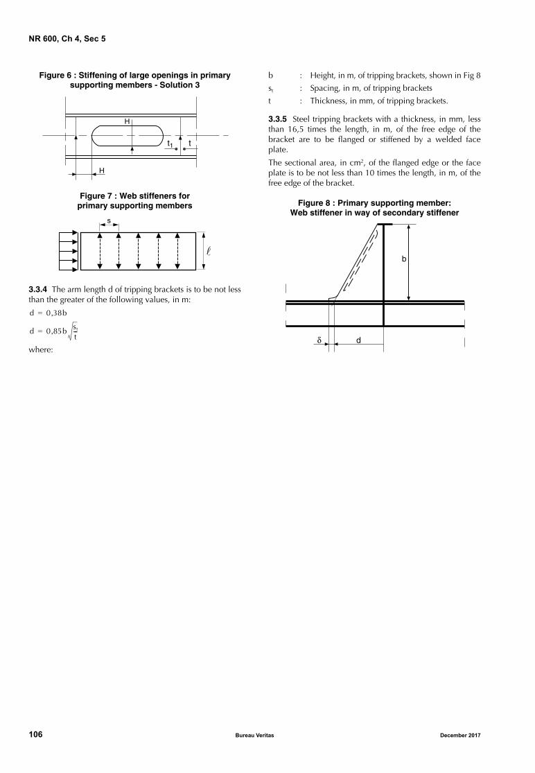
NR 600, Ch 4, Sec 5
Figure 6 : Stiffening of large openings in primary supporting members - Solution 3
Figure 7 : Web stiffeners for primary supporting members
3.3.4 The arm length d of tripping brackets is to be not lessthan the greater of the following values, in m:
where:
b : Height, in m, of tripping brackets, shown in Fig 8
st : Spacing, in m, of tripping brackets
t : Thickness, in mm, of tripping brackets.
3.3.5 Steel tripping brackets with a thickness, in mm, lessthan 16,5 times the length, in m, of the free edge of thebracket are to be flanged or stiffened by a welded faceplate.
The sectional area, in cm2, of the flanged edge or the faceplate is to be not less than 10 times the length, in m, of thefree edge of the bracket.
Figure 8 : Primary supporting member: Web stiffener in way of secondary stiffener
t1 t
H
H
s
d 0 38b,=
d 0 85b st
t---,=
b
dδ
106 Bureau Veritas December 2017

NR 600, Ch 4, Sec 6
SECTION 6 STIFFENER BRACKETS SCANTLING AND STIFFENER END CONNECTIONS
1 General arrangement of brackets
1.1 Materials
1.1.1 The requirements of the present Section are applica-ble to hull made totally or partly in steel.
For ship hulls built in aluminium alloys, the requirements toapply are defined in NR561 Aluminium Ships, Section 6.
For ship hulls built in composite materials, the requirementsto apply are defined in NR546 Composite Ships.
1.2 General requirements
1.2.1 As a general rules, brackets are to be provided at thestiffener ends when the continuity of the web and the flangeof the stiffeners is not ensured in way of their supports.
1.2.2 Arm of end brackets are to be of the same length, asfar as practicable.
1.2.3 The section of the end bracket web is generally to benot less than that of the supported stiffener.
1.2.4 The section modulus of the end bracket is to be atleast equal to the section modulus of the stiffener supportedby the bracket.
When the bracket is flanged, the section modulus is to beexamined in way of flange as well as in way of the end ofthe flange.
Figure 1 : Bracket at upper end of secondary stiffener on plane bulkhead
1.2.5 Bracket flanges
Steel brackets having a thickness, in mm, less than 16,5 Lb
are to be flanged or stiffened by a welded face plate, suchthat:
• the sectional area, in cm2, of the flanged edge or theface plate is at least equal to 10 Lb
• the thickness of the bracket flange is not less than that ofthe bracket web,
where:
Lb : length, in m, of the free edge of the bracket.
1.2.6 When a face plate is welded on end brackets to bestrengthened, this face plate is to be symmetrical.
In such a case, the following arrangements are to be com-plied with, as a rule:
• the face plates are to be snipped at the ends, with totalangle not greater than 30°
• the width of the face plates at ends is not to exceed25 mm
• the face plates being 20 mm thick or above are to betapered at ends over half the thickness
• the radius of the curved face plate is to be as large aspossible
• a collar plate is to be fitted in way of bracket toes
• the fillet weld throat thickness is to be not less than t/2,where t is the thickness at the bracket toe.
Figure 2 : Bracket at lower end of secondary stiffener on plane bulkhead
d
d
hs
d
d
hs
December 2017 Bureau Veritas 107
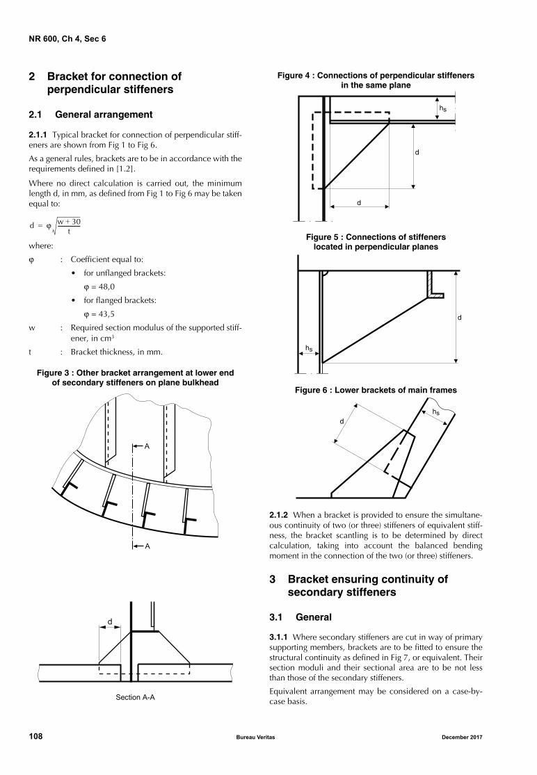
NR 600, Ch 4, Sec 6
2 Bracket for connection of perpendicular stiffeners
2.1 General arrangement
2.1.1 Typical bracket for connection of perpendicular stiff-eners are shown from Fig 1 to Fig 6.
As a general rules, brackets are to be in accordance with therequirements defined in [1.2].
Where no direct calculation is carried out, the minimumlength d, in mm, as defined from Fig 1 to Fig 6 may be takenequal to:
where:
ϕ : Coefficient equal to:
• for unflanged brackets:
ϕ = 48,0
• for flanged brackets:
ϕ = 43,5
w : Required section modulus of the supported stiff-ener, in cm3
t : Bracket thickness, in mm.
Figure 3 : Other bracket arrangement at lower end of secondary stiffeners on plane bulkhead
Figure 4 : Connections of perpendicular stiffeners in the same plane
Figure 5 : Connections of stiffeners located in perpendicular planes
Figure 6 : Lower brackets of main frames
2.1.2 When a bracket is provided to ensure the simultane-ous continuity of two (or three) stiffeners of equivalent stiff-ness, the bracket scantling is to be determined by directcalculation, taking into account the balanced bendingmoment in the connection of the two (or three) stiffeners.
3 Bracket ensuring continuity of secondary stiffeners
3.1 General
3.1.1 Where secondary stiffeners are cut in way of primarysupporting members, brackets are to be fitted to ensure thestructural continuity as defined in Fig 7, or equivalent. Theirsection moduli and their sectional area are to be not lessthan those of the secondary stiffeners.
Equivalent arrangement may be considered on a case-by-case basis.
d ϕ w 30+t
-----------------=
A
A
Section A-A
d
d
hs
d
d
hs
dhs
108 Bureau Veritas December 2017

NR 600, Ch 4, Sec 6
Figure 7 : End connection of secondary stiffener Backing bracket
4 Bracketless end stiffeners connections
4.1 Bracketless end connections
4.1.1 Case of two stiffenersIn the case of bracketless crossing between two primarysupporting members (see Fig 8), the thickness tb of the com-mon part of the webs, in mm, is to be not less than thegreater value obtained from the following formulae:
tb = Min (t1 ; t2 )
where:
Sf1 , Sf2 : Flange sections, in mm2,of member 1 and mem-ber 2, respectively
σ1 , σ2 : Actual normal stresses, in N/mm2, in member 1and member 2, respectively
ReH : Minimum yield stress, in N/mm2, as defined inCh 1, Sec 2, of the material of the web of pri-mary supporting member.
4.1.2 Case of three stiffenersIn the case of bracketless crossing between three primarysupporting members (see Fig 9), and when the flange conti-nuity is ensured between member 2 and member 3, thethickness tb of the common part of the webs, in mm, is to benot less than:
ReH : As defined in [4.1.1].
When the flanges of member 2 and member 3 are not con-tinuous, the thickness of the common part of the webs is tobe defined as [4.1.1].
4.1.3 Stiffening of common part of websWhen the minimum value of heights h1 and h2 of the mem-ber 1 and member 2 is greater than 100 tb , the commonpart of the webs is generally to be stiffened.
4.1.4 Lamellar tearing in way of flangesWhen lamellar tearing of flanges is likely to occur, a 100%ultrasonic testing of the flanges in way of the weld may berequired after welding.
Figure 8 : Bracketless end connections between two primary supporting members
Figure 9 : Bracketless end connections between three primary supporting members
4.2 Other type of end connection
4.2.1 Where end connections are made according to Fig 10,a stiffener with sniped ends is to be fitted on connection web,when:
a > 100 t
where:
a : Dimension, in mm, measured as shown on Fig 10
t : Web thickness, in mm.
Figure 10 : End connection with stiffener
tbSf1σ1
0 4h2ReH,------------------------=
tbSf2σ2
0 4h1ReH,------------------------=
tbSf1σ1
0 4h2ReH,------------------------=
Member 2
Member 1
h1tb
h2
Member 2
Member 1
Member 3
h1tb
h2
�
�
���������
�
December 2017 Bureau Veritas 109
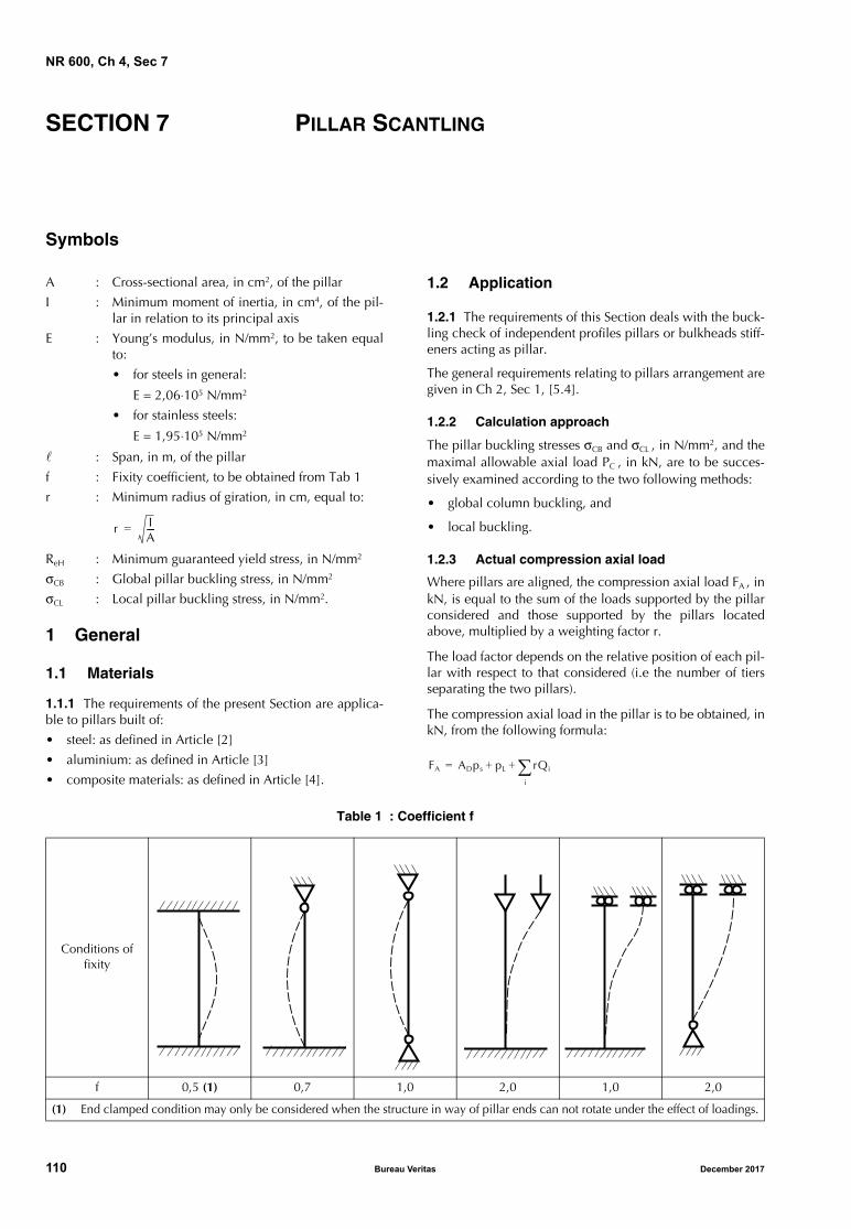
NR 600, Ch 4, Sec 7
SECTION 7 PILLAR SCANTLING
Symbols
A : Cross-sectional area, in cm2, of the pillar
I : Minimum moment of inertia, in cm4, of the pil-lar in relation to its principal axis
E : Young’s modulus, in N/mm2, to be taken equalto:
• for steels in general:
E = 2,06⋅105 N/mm2
• for stainless steels:
E = 1,95⋅105 N/mm2
: Span, in m, of the pillar
f : Fixity coefficient, to be obtained from Tab 1
r : Minimum radius of giration, in cm, equal to:
ReH : Minimum guaranteed yield stress, in N/mm2
σCB : Global pillar buckling stress, in N/mm2
σCL : Local pillar buckling stress, in N/mm2.
1 General
1.1 Materials
1.1.1 The requirements of the present Section are applica-ble to pillars built of:
• steel: as defined in Article [2]
• aluminium: as defined in Article [3]
• composite materials: as defined in Article [4].
1.2 Application
1.2.1 The requirements of this Section deals with the buck-ling check of independent profiles pillars or bulkheads stiff-eners acting as pillar.
The general requirements relating to pillars arrangement aregiven in Ch 2, Sec 1, [5.4].
1.2.2 Calculation approach
The pillar buckling stresses σCB and σCL , in N/mm2, and themaximal allowable axial load PC , in kN, are to be succes-sively examined according to the two following methods:
• global column buckling, and
• local buckling.
1.2.3 Actual compression axial load
Where pillars are aligned, the compression axial load FA , inkN, is equal to the sum of the loads supported by the pillarconsidered and those supported by the pillars locatedabove, multiplied by a weighting factor r.
The load factor depends on the relative position of each pil-lar with respect to that considered (i.e the number of tiersseparating the two pillars).
The compression axial load in the pillar is to be obtained, inkN, from the following formula:
Table 1 : Coefficient f
r IA----=
FA ADps pL ri Qi+ +=
Conditions of fixity
f 0,5 (1) 0,7 1,0 2,0 1,0 2,0
(1) End clamped condition may only be considered when the structure in way of pillar ends can not rotate under the effect of loadings.
110 Bureau Veritas December 2017
NR 600, Ch 4, Sec 7
where:AD : Area, in m2, of the portion of the deck or the
platform supported by the pillar consideredps : Pressure on deck, in kN/m2, as defined in Ch 3,
Sec 4pL : Local load on deck, in kN, if any Ch 3, Sec 4r : Load factor depending on the relative position
of each pillar above the one considered, to betaken equal to:• r = 0,9 for the pillar immediately above the
pillar considered
• r = 0,9i > 0,478 for the ith pillar of the lineabove the pillar considered
Qi : Vertical local load, in kN, supported by the ith
pillar of the line above the pillar considered, ifany.
2 Pillar in steel material
2.1 Buckling of pillars subjected to compres-sion axial load
2.1.1 Global critical column buckling stressThe global critical column buckling stress of pillars σCB is tobe obtained, in N/mm2, from the following formulae:
where:σE : Euler column buckling stress of the pillar, in
N/mm2, to be obtain by the following formula:
2.1.2 Local critical buckling stress The local critical buckling stress of pillars σCL is to beobtained, in N/mm2, from the following formulae:
where:σEi : Euler local buckling stress, in N/mm2, to be
taken equal to the values obtained from the fol-lowing formulae:• For circular tubular pillars:
where:t : Pillar thickness, in mmD : Pillar outer diameter, in mm
• For rectangular tubular pillars:
where:b : Greatest dimension of the cross-
section, in mmt : Plating thickness in relation to b,
in mm• For built up pillars, the lesser of:
where:hW : Web height of built-up section,
in mmtW : Web thickness of built-up sec-
tion, in mmbF : Face plate width of built-up sec-
tion, in mmtF : Face plate thickness of built-up
section, in mm.
2.1.3 Maximum allowable axial loadThe maximum allowable axial load PC , in kN, is the smallerof the two following values:
2.2 Buckling of pillars subjected to compres-sion axial load and bending moments
2.2.1 Checking criteriaIn addition to the requirements in [2.1], the scantling of thepillar loaded by the compression axial load and bendingmoments are to comply with the following formula:
where:F : Actual compression load, in kN, acting on the
pillarA : Cross-sectional area, in cm2, of the pillare : Eccentricity, in cm, of the compression load
with respect to the centre of gravity of the cross-section
σE : Euler column buckling stress, in N/mm2,defined in [2.1.1]
wP : Minimum section modulus, in cm3, of the cross-section of the pillar
Mmax : Max (M1, M2, M0)
M1 : Bending moment, in kN.m, at the upper end ofthe pillar
M2 : Bending moment, in kN.m, at the lower end ofthe pillar
σCB σE for σEReH
2--------≤=
σCB ReH 1ReH
4σE
---------– for σE
ReH
2-------->=
σE π2E IA f( )2----------------10 4–=
σCL σEi for σEiReH
2--------≤=
σCL ReH 1ReH
4σEi
----------– for σEi
ReH
2-------->=
σEi 12 5 E206000-------------------- t
D---- 104,=
σEi 78 E206000-------------------- t
b---
2
104=
σEi 78 E206000-------------------- tW
hW
-------
2
104=
σEi 32 E206000-------------------- tF
bF
-----
2
104=
PCσCB
1 35,-------------A 10 1–⋅=
PC σCLA 10 1–⋅=
10F 1A---- Φe
wP
--------+ 103Mmax
wP
------------ + 0 85ReH,≤
Φ 1
1 10FσEA----------–
-------------------=
December 2017 Bureau Veritas 111
NR 600, Ch 4, Sec 7
provided that:
2.3 Pillars in tanks
2.3.1 Where pillars are submitted to tensile stress due tointernal pressure in tanks, brackets or equivalent arrange-ments are to be provided in way of the connection elementsbetween the pillar and the supported structure of the tank.Doubling plate are not to be used at pillar ends.
Pillars in tanks are not to be of hollow profile type.
2.4 Vertical bulkhead stiffener acting as pillar
2.4.1 When a vertical stiffening member is fitted on thebulkhead in line with the deck primary supporting membertransferring the loads from the deck to the bulkhead (as apillar), this vertical stiffener is to be calculated as defined in[2.1] or [2.2], taking into account an associated plating of awidth equal to 30 times the plating thickness.
3 Pillar in aluminium material
3.1 General
3.1.1 The global critical column buckling stress σCB and thelocal critical buckling stress σCL , in N/mm2, of a pillar builtin aluminium material are to be as defined in NR561 Alu-minium Ships, Section 8.
3.1.2 Maximum allowable axial loadThe maximum allowable axial load PC , in kN, is to be asdefined in NR561 Aluminium Ships, Section 8, taking intoaccount the following values of SFCB and SFCL:
SFCL = 1,0
4 Pillar in composite material
4.1 Scantling criteria
4.1.1 The compression and buckling check of pillars madeof composite materials are to be carried out according toNR546 Composite ships, Section 9, taking into account thefollowing Rules safety factors in relation to the scantling cri-teria:
• Maximum stress in each layer:
SF = 1,2 CF CR
• Combined stress in each layer:
SFCS = 1,2 CCS CF
• Local buckling:
SFlBuck = 1,35 CF
• Global buckling:
SFgBuck = 1,75 CF
where
CF, CR : Partial safety factors defined in Ch 2, Sec 3,[3.2.2]
CCS : For unidirectional tape, bi-bias, three unidirec-tional fabric:
CCS = 1,7 , or
For other type of layer:
CCS = 2,1
M00 5 1 t2+( ), M1 M2+( )
u( )cos----------------------------------------------------------=
u 0 5π, 10FσEA----------=
t 1u( )tan
----------------- M2 M1–M2 M1+--------------------- =
utan2– M2 M1–M2 M1+--------------------- utan2≤ ≤
SFCB 0 34fr----, 1 15,+=
112 Bureau Veritas December 2017
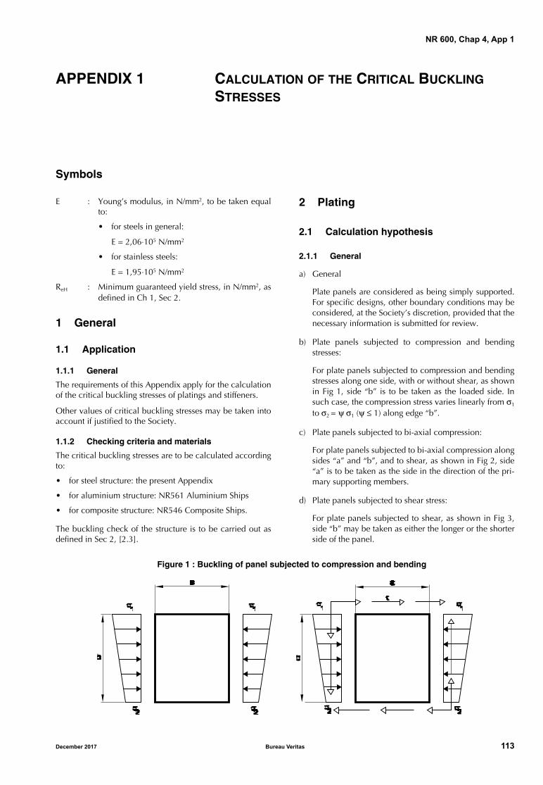
NR 600, Chap 4, App 1
APPENDIX 1 CALCULATION OF THE CRITICAL BUCKLING STRESSES
Symbols
E : Young’s modulus, in N/mm2, to be taken equalto:
• for steels in general:
E = 2,06⋅105 N/mm2
• for stainless steels:
E = 1,95⋅105 N/mm2
ReH : Minimum guaranteed yield stress, in N/mm2, asdefined in Ch 1, Sec 2.
1 General
1.1 Application
1.1.1 General
The requirements of this Appendix apply for the calculationof the critical buckling stresses of platings and stiffeners.
Other values of critical buckling stresses may be taken intoaccount if justified to the Society.
1.1.2 Checking criteria and materials
The critical buckling stresses are to be calculated accordingto:
• for steel structure: the present Appendix
• for aluminium structure: NR561 Aluminium Ships
• for composite structure: NR546 Composite Ships.
The buckling check of the structure is to be carried out asdefined in Sec 2, [2.3].
2 Plating
2.1 Calculation hypothesis
2.1.1 General
a) General
Plate panels are considered as being simply supported.For specific designs, other boundary conditions may beconsidered, at the Society’s discretion, provided that thenecessary information is submitted for review.
b) Plate panels subjected to compression and bendingstresses:
For plate panels subjected to compression and bendingstresses along one side, with or without shear, as shownin Fig 1, side “b” is to be taken as the loaded side. Insuch case, the compression stress varies linearly from σ1
to σ2 = ψ σ1 (ψ ≤ 1) along edge “b”.
c) Plate panels subjected to bi-axial compression:
For plate panels subjected to bi-axial compression alongsides “a” and “b”, and to shear, as shown in Fig 2, side“a” is to be taken as the side in the direction of the pri-mary supporting members.
d) Plate panels subjected to shear stress:
For plate panels subjected to shear, as shown in Fig 3,side “b” may be taken as either the longer or the shorterside of the panel.
Figure 1 : Buckling of panel subjected to compression and bending
December 2017 Bureau Veritas 113
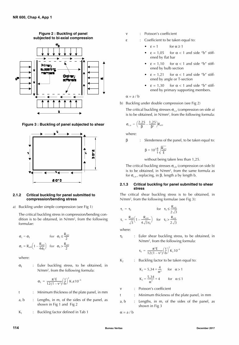
NR 600, Chap 4, App 1
Figure 2 : Buckling of panel subjected to bi-axial compression
Figure 3 : Buckling of panel subjected to shear
2.1.2 Critical buckling for panel submitted to compression/bending stress
a) Buckling under simple compression (see Fig 1)
The critical buckling stress in compression/bending con-dition is to be obtained, in N/mm2, from the followingformulae:
where:
σE : Euler buckling stress, to be obtained, inN/mm2, from the following formula:
t : Minimum thickness of the plate panel, in mm
a, b : Lengths, in m, of the sides of the panel, asshown in Fig 1 and Fig 2
K1 : Buckling factor defined in Tab 1
ν : Poisson’s coefficient
ε : Coefficient to be taken equal to:
• ε = 1 for α ≥ 1
• ε = 1,05 for α < 1 and side “b” stiff-ened by flat bar
• ε = 1,10 for α < 1 and side “b” stiff-ened by bulb section
• ε = 1,21 for α < 1 and side “b” stiff-ened by angle or T-section
• ε = 1,30 for α < 1 and side “b” stiff-ened by primary supporting members.
α = a / b
b) Buckling under double compression (see Fig 2)
The critical buckling stresses σc,a (compression on side a)is to be obtained, in N/mm2, from the following formula:
where:
β : Slenderness of the panel, to be taken equal to:
without being taken less than 1,25.
The critical buckling stresses σc,b (compression on side b)is to be obtained, in N/mm2, from the same formula asfor σc,a , replacing, in β, length a by length b.
2.1.3 Critical buckling for panel submitted to shear stress
The critical shear buckling stress is to be obtained, inN/mm2, from the following formulae (see Fig 3):
where:
τE : Euler shear buckling stress, to be obtained, inN/mm2, from the following formula:
K2 : Buckling factor to be taken equal to:
ν : Poisson’s coefficient
t : Minimum thickness of the plate panel, in mm
a, b : Lengths, in m, of the sides of the panel, asshown in Fig 3
α = a / b
σc σE = for σEReH
2--------≤
σc ReH 1ReH
4σE
---------– = for σE
ReH
2-------->
σEπ2E
12 1 ν2–( )-------------------------- t
b---
2
K1ε10 6–=
σc a,2 25,
β----------- 1 25,
β2-----------–
ReH=
β 103= at--- ReH
E--------
τc τE for τEReH
2 3-----------≤=
τcReH
3-------- 1
ReH
4 3τE
----------------– for τE
ReH
2 3----------->=
τEπ2E
12 1 ν2–( )-------------------------- t
b---
2
K210 6–=
K2 5= 34, 4α2------ for α 1>+
K25 34,
α2-----------= 4 for α 1≤+
114 Bureau Veritas December 2017
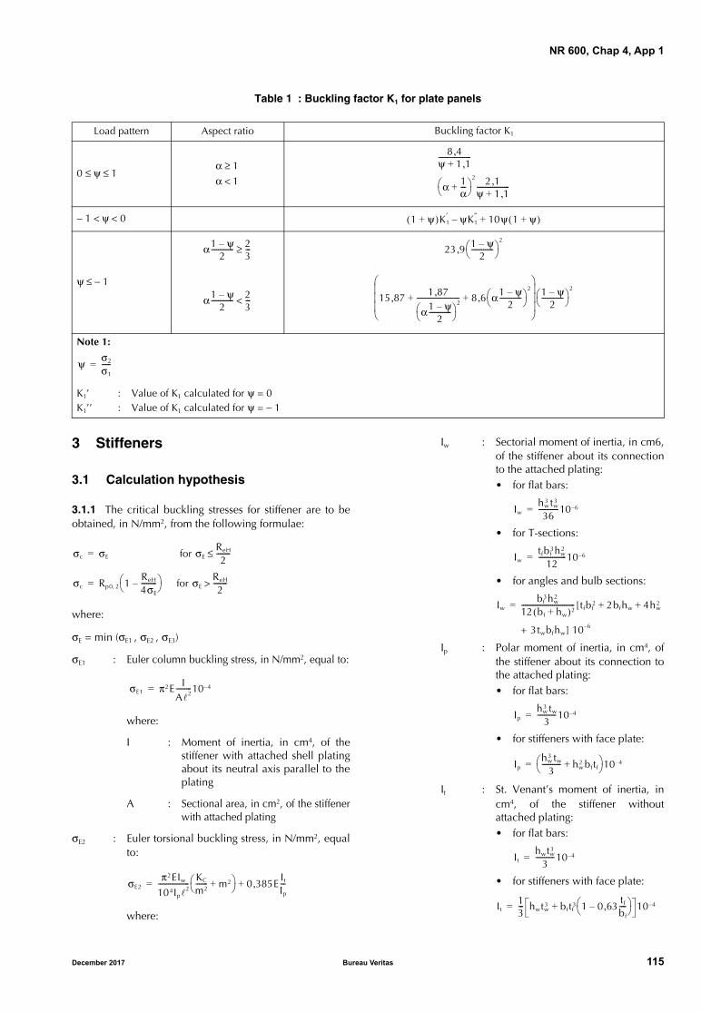
NR 600, Chap 4, App 1
Table 1 : Buckling factor K1 for plate panels
3 Stiffeners
3.1 Calculation hypothesis
3.1.1 The critical buckling stresses for stiffener are to beobtained, in N/mm2, from the following formulae:
where:
σE = min (σE1 , σE2 , σE3)
σE1 : Euler column buckling stress, in N/mm2, equal to:
where:
I : Moment of inertia, in cm4, of thestiffener with attached shell platingabout its neutral axis parallel to theplating
A : Sectional area, in cm2, of the stiffenerwith attached plating
σE2 : Euler torsional buckling stress, in N/mm2, equalto:
where:
Iw : Sectorial moment of inertia, in cm6,of the stiffener about its connectionto the attached plating:• for flat bars:
• for T-sections:
• for angles and bulb sections:
Ip : Polar moment of inertia, in cm4, ofthe stiffener about its connection tothe attached plating:• for flat bars:
• for stiffeners with face plate:
It : St. Venant’s moment of inertia, incm4, of the stiffener withoutattached plating:• for flat bars:
• for stiffeners with face plate:
Load pattern Aspect ratio Buckling factor K1
0 ≤ ψ ≤ 1
− 1 < ψ < 0
ψ ≤ − 1
Note 1:
K1’ : Value of K1 calculated for ψ = 0 K1’’ : Value of K1 calculated for ψ = − 1
α 1≥α 1<
8 4,ψ 1 1,+-------------------
α 1α---+
2 2 1,ψ 1 1,+-------------------
1 ψ+( )K1′ ψK1
″ 10ψ 1 ψ+( )+–
α1 ψ–2
------------- 23---≥ 23 9 1 ψ–
2-------------
2
,
α1 ψ–2
------------- 23---< 15 87, 1 87,
α1 ψ–2
-------------
2------------------------- 8 6 α1 ψ–
2-------------
2
,+ +
1 ψ–2
-------------
2
ψ σ2
σ1
-----=
σc σE= for σEReH
2--------≤
σc Rp0 2, 1ReH
4σE
---------– for σE
ReH
2-------->=
σE1 π2E IA2---------10 4–=
σE2π2EIw
104Ip2
------------------ KC
m2------- m2+ 0 385, E
It
Ip
---+=
Iwhw
3 tw3
36------------10 6–=
Iwtfbf
3hw2
12----------------10 6–=
Iwbf
3hw2
12 bf hw+( )2------------------------------- [tfbf
2 2bfhw 4hw2+ +=
+ 3twbfhw] 10 6–
Iphw
3 tw
3-----------10 4–=
Iphw
3 tw
3----------- hw
2 bftf+ 10 4–=
Ithwtw
3
3-----------10 4–=
It13--- hwtw
3 bftf3 1 0 63, tf
bf
----– + 10 4–=
December 2017 Bureau Veritas 115

NR 600, Chap 4, App 1
m : Number of half waves, to be takenequal to the integer number suchthat (see also Tab 2):
m2 (m − 1)2 ≤ KC < m2 (m + 1)2
C0 : Spring stiffness of the attached plat-ing:
σE3 : Euler web buckling stress, in N/mm2, equal to:• for flat bars:
• for stiffeners with face plate:
Table 2 : Torsional buckling of axially loaded stiffeners Number m of half waves
KCC0
4
π4EIw
--------------106=
C0Etp
3
2 73, s--------------10 3–=
KC
m 1 2 3
σE3 16tW
hW
-------
2
104=
σE3 78tW
hW
-------
2
104=
0 KC≤ 4< 4 KC≤ 36< 36 KC≤ 144<
116 Bureau Veritas December 2017
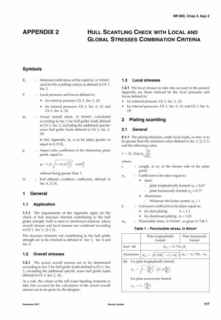
NR 600, Chap 4, App 2
APPENDIX 2 HULL SCANTLING CHECK WITH LOCAL AND GLOBAL STRESSES COMBINATION CRITERIA
Symbols
Ry : Minimum yield stress of the material, in N/mm2,used for the scantling criteria as defined in Ch 1,Sec 2
P : Local pressures and forces defined in:
• for external pressure: Ch 3, Sec 3, [2]
• for internal pressures: Ch 3, Sec 4, [3] andCh 3, Sec 4, [4]
σA : Actual overall stress, in N/mm2, calculatedaccording to Sec 2 for hull girder loads definedin Ch 3, Sec 2, excluding the additional specificwave hull girder loads defined in Ch 3, Sec 2,[6]
In this Appendix, σA is to be taken greater orequal to 0,35 Ry.
μ : Aspect ratio coefficient of the elementary platepanel, equal to:
without being greater than 1.
m : End stiffener condition coefficient, defined inSec 4, [1.4].
1 General
1.1 Application
1.1.1 The requirements of this Appendix apply for thecheck of hull structure element contributing to the hullgirder strength, built in steel or aluminium material, whereoverall stresses and local stresses are combined accordingto Ch 1, Sec 3, [2.1.2].
The structure elements not contributing to the hull girderstrength are to be checked as defined in Sec 3, Sec 4 andSec 5.
1.2 Overall stresses
1.2.1 The actual overall stresses are to be determinedaccording to Sec 2 for hull girder loads defined in Ch 3, Sec2, excluding the additional specific wave hull girder loadsdefined in Ch 3, Sec 2, [6].
As a rule, the values of the still water bending moments totake into account for the calculation of the actual overallstresses are to be given by the designer.
1.3 Local stresses
1.3.1 The local stresses to take into account in the presentAppendix are those induced by the local pressures andforces defined in:• for external pressure: Ch 3, Sec 3, [2]• for internal pressures: Ch 3, Sec 4, [3] and Ch 3, Sec 4,
[4]
2 Plating scantling
2.1 General
2.1.1 The plating thickness under local loads, in mm, is tobe greater than the minimum value defined in Sec 3, [2.2.1]and the following value:
where:s : Length, in m, of the shorter side of the plate
panelnp : Coefficient to be taken equal to:
• Steel:- plate longitudinally framed: np = 0,67
- plate transversely framed: np = 0,77
• Aluminium:- Whatever the frame system: np = 1
λ : Corrosion coefficient to be taken equal to:• for steel plating: λ = 1,1 • for aluminium plating: λ = 1,05
σad : Permissible stress, in N/mm2, as given in Tab 1.
Table 1 : Permissible stress, in N/mm2
μ 1= 21 1 0 33 s--
2
,+, 0 69s--,–
Plate longitudinally framed
Plate transversely framed
Steel (1)
Aluminium
(1) For plate longitudinally framed:
For plate transversely framed:
t 22 4λμsnpP
σad
-------,=
σad 0 75λLTRy,=
σad 0 55Ry2, 1 1σA
2,( )–= σad 0 75Ry, σA–=
λLT 1σA
Ry------
2
– 0 25σA
Ry------,
–=
λLT 1σA
Ry------ –=
December 2017 Bureau Veritas 117
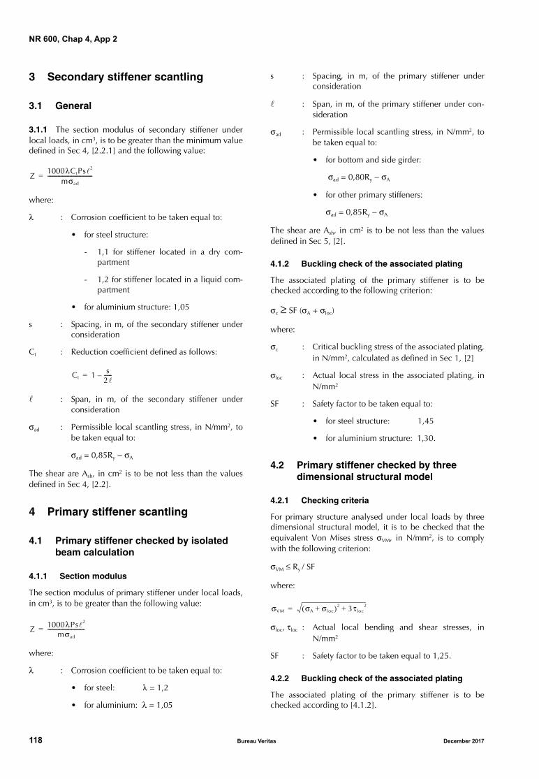
NR 600, Chap 4, App 2
3 Secondary stiffener scantling
3.1 General
3.1.1 The section modulus of secondary stiffener underlocal loads, in cm3, is to be greater than the minimum valuedefined in Sec 4, [2.2.1] and the following value:
where:
λ : Corrosion coefficient to be taken equal to:
• for steel structure:
- 1,1 for stiffener located in a dry com-partment
- 1,2 for stiffener located in a liquid com-partment
• for aluminium structure: 1,05
s : Spacing, in m, of the secondary stiffener underconsideration
Ct : Reduction coefficient defined as follows:
: Span, in m, of the secondary stiffener underconsideration
σad : Permissible local scantling stress, in N/mm2, tobe taken equal to:
σad = 0,85Ry − σA
The shear are Ash, in cm2 is to be not less than the valuesdefined in Sec 4, [2.2].
4 Primary stiffener scantling
4.1 Primary stiffener checked by isolated beam calculation
4.1.1 Section modulus
The section modulus of primary stiffener under local loads,in cm3, is to be greater than the following value:
where:
λ : Corrosion coefficient to be taken equal to:
• for steel: λ = 1,2
• for aluminium: λ = 1,05
s : Spacing, in m, of the primary stiffener underconsideration
: Span, in m, of the primary stiffener under con-sideration
σad : Permissible local scantling stress, in N/mm2, tobe taken equal to:
• for bottom and side girder:
σad = 0,80Ry − σA
• for other primary stiffeners:
σad = 0,85Ry − σA
The shear are Ash, in cm2 is to be not less than the valuesdefined in Sec 5, [2].
4.1.2 Buckling check of the associated plating
The associated plating of the primary stiffener is to bechecked according to the following criterion:
σc ≥ SF (σA + σloc)
where:
σc : Critical buckling stress of the associated plating,in N/mm2, calculated as defined in Sec 1, [2]
σloc : Actual local stress in the associated plating, inN/mm2
SF : Safety factor to be taken equal to:
• for steel structure: 1,45
• for aluminium structure: 1,30.
4.2 Primary stiffener checked by three dimensional structural model
4.2.1 Checking criteria
For primary structure analysed under local loads by threedimensional structural model, it is to be checked that theequivalent Von Mises stress σVM, in N/mm2, is to complywith the following criterion:
σVM ≤ Ry / SF
where:
σloc, τloc : Actual local bending and shear stresses, inN/mm2
SF : Safety factor to be taken equal to 1,25.
4.2.2 Buckling check of the associated plating
The associated plating of the primary stiffener is to bechecked according to [4.1.2].
Z1000λCtPs2
mσad
----------------------------------=
Ct 1 s2------–=
Z 1000λPs2
mσad
----------------------------=
σVM σA σloc+( )2 3τloc2+=
118 Bureau Veritas December 2017
NR 600
Chapter 5
OTHER STRUCTURES
SECTION 1 SUPERSTRUCTURES AND DECKHOUSES
SECTION 2 OTHER STRUCTURES
SECTION 3 HELICOPTER DECKS AND PLATFORMS
SECTION 4 ANCHORING EQUIPMENT AND SHIPBOARD FITTINGS FOR ANCHORING, MOORING AND TOWING EQUIPMENT
December 2017 Bureau Veritas 119

120 Bureau Veritas December 2017
NR 600, Ch 5, Sec 1
SECTION 1 SUPERSTRUCTURES AND DECKHOUSES
Symbols
LWL : Length at waterline at full load, in m
LLL : Load line length, in m
B : Moulded breadth, in m
T : Draught, at full load displacement, in m, meas-ured from the base line (see Ch 3, Sec 3, Fig 1)
s : Length, in m, of the shorter side of the platepanel
: Length, in m, of the longer side of the platepanel
k : Material factor, defined in Ch 1, Sec 2, [2] forsteel and in Ch 1, Sec 2, [3] for aluminiumalloys
μ : Aspect ratio coefficient of the elementary platepanel, equal to:
σlocam : Local permissible bending stress, in N/mm2, asdefined in Ch 2, Sec 3
z : Distance, in m, between the base line and thecalculation point (see Ch 3, Sec 3, Fig 1)
τlocam : Local permissible shear stress, in N/mm2, asdefined in Ch 2, Sec 3
m : End stiffener condition coefficient, as defined inCh 4, Sec 4, [1.4]
n : Coefficient navigation defined in Ch 1, Sec 1,Tab 2.
1 General
1.1 Application
1.1.1 The requirements of this Section apply for the scant-ling of plating and associated structures of front, side and aftbulkheads and decks of superstructures and deckhouses.
1.1.2 Superstructures contributing to the hull longitudinalstrength are to be examined taking into account the hullanalysis approach defined in Ch 1, Sec 3, [2].
1.1.3 Materials
Attention is drawn to the selection of building materialswhich is not only to be determined from strength considera-tion, but should also give consideration to structural fireprotection and associated class requirements or FlagAdministration requirements, where applicable.
1.2 Definitions
1.2.1 Superstructure
A superstructure is a decked structure connected to the free-board deck, extending from side to side of the ship or withthe side plating not being inboard of the shell plating than0,04 B.
1.2.2 Deckhouse
A deckhouse is a decked structure other than a superstruc-ture, located on the freeboard deck or above.
1.2.3 Superstructures and deckhouses contributing to the longitudinal strength
A superstructures and/or deckhouses extending over 0,4 Lmay generally be considered as contributing to the hull lon-gitudinal girder strength.
In this case, a global strength analysis as defined in Ch 4,Sec 2 is to be carried out for the structure elements contrib-uting to the hull longitudinal girder strength.
1.2.4 Tiers of superstructures and deckhouses
The lowest tier is normally that which is directly situatedabove the freeboard deck.
The second tier is that located immediately above the low-est tier, and so on.
1.2.5 Standard height of superstructure
The standard height of superstructure is defined in Tab 1.
Table 1 : Standard height of superstructure
1.2.6 Position 1 and position 2
a) Position 1 includes:
• exposed freeboard and raised quarter decks
• exposed superstructure decks situated forward of0,25 LLL from the perpendicular, at the forward sideof the stem, to the waterline at 85% of the leastmoulded depth measured from the top of the keel.
μ 1= 21 1 0 33 s--
2
,+, 0 69s-- 1≤,–
Load line length LLL ,
in m
Standard height hS, in m
Raised quarter deck
All othersuperstructures
LLL ≤ 30 0,90 1,80
30 < LLL < 65 0,9 + 0,00667 (LLL − 30) 1,80
December 2017 Bureau Veritas 121
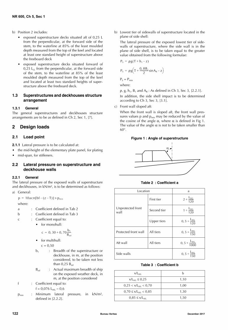
NR 600, Ch 5, Sec 1
b) Position 2 includes:• exposed superstructure decks situated aft of 0,25 L
from the perpendicular, at the forward side of thestem, to the waterline at 85% of the least mouldeddepth measured from the top of the keel and locatedat least one standard height of superstructure abovethe freeboard deck
• exposed superstructure decks situated forward of0,25 LLL from the perpendicular, at the forward sideof the stem, to the waterline at 85% of the leastmoulded depth measured from the top of the keeland located at least two standard heights of super-structure above the freeboard deck.
1.3 Superstructures and deckhouses structure arrangement
1.3.1 GeneralThe general superstructures and deckhouses structurearrangements are to be as defined in Ch 2, Sec 1, [7].
2 Design loads
2.1 Load point
2.1.1 Lateral pressure is to be calculated at:• the mid-height of the elementary plate panel, for plating• mid-span, for stiffeners.
2.2 Lateral pressure on superstructure and deckhouse walls
2.2.1 GeneralThe lateral pressure of the exposed walls of superstructureand deckhouses, in kN/m², is to be determined as follows:
a) General:
where:a : Coefficient defined in Tab 2b : Coefficient defined in Tab 3c : Coefficient equal to:
• for monohull:
• for multihull:c = 0,50
b1 : Breadth of the superstructure ordeckhouse, in m, at the positionconsidered, to be taken not lessthan 0,25 Bed
Bed : Actual maximum breadth of shipon the exposed weather deck, inm, at the position considered
f : Coefficient equal to:f = 0,076 LWL − 0,6
pmin : Minimum lateral pressure, in kN/m²,defined in [2.2.2].
b) Lowest tier of sidewalls of superstructure located in theplane of side shell:
The lateral pressure of the exposed lowest tier of side-walls of superstructure, where the side wall is in theplane of side shell, is to be taken equal to the greatervalue obtained from the following formulae:
PS = Pmin
where:
ρ, g, h1, B1 and AR : As defined in Ch 3, Sec 3, [2.2.1].
In addition, the side shell impact is to be determinedaccording to Ch 3, Sec 3, [3.1].
c) Front wall sloped aft:
When the front wall is sloped aft, the front wall pres-sures values p and pmin may be reduced by the value ofthe cosine of the angle α, where α is defined in Fig 1.The value of the angle α is not to be taken smaller than60°.
Figure 1 : Angle of superstructure
Table 2 : Coefficient a
Table 3 : Coefficient b
p 10acn bf z T–( )–[ ] pmin>=
c 0 30 0 70b1
Bed
-------,+,=
Location a
Unprotected front wall
First tier
Second tier
Upper tiers
Protected front wall All tiers
Aft wall All tiers
Side walls
x/LWL b
x/LWL ≤ 0,25 1,10
0,25 < x/LWL < 0,70 1,00
0,70 ≤ x/LWL < 0,85 1,30
0,85 ≤ x/LWL 1,50
PS ρg T h1 z–+( )=
PS ρg T0 8B, 1
2----------------+ ARsin z–
=
2LWL
120----------+
1LWL
120----------+
0 5,LWL
120----------+
0 5,LWL
150----------+
0 5,LWL
1000-------------+
0 5,LWL
150----------+
122 Bureau Veritas December 2017

NR 600, Ch 5, Sec 1
Table 4 : Minimum lateral pressurefor superstructures and deckhouses
2.2.2 Minimum lateral pressure
The values of the minimum lateral pressures pmin, in KN/m2,are defined in Tab 4.
Apart from the lower tier of unprotected front wall of super-structure, pmin may be taken equal to 2,5 kN/m2 when:
z > T + 0,5 B1 AR + h1
where:
z : Z co-ordinate, in m, of the calculation point asdefined in Ch 3, Sec 1, [4.1.1]
T : Moulded draught, in m, as defined in Ch 1, Sec 1,[4.5]
h1 : Ship relative motion, in m, in the consideredlongitudinal part of the ship as defined in Ch 3,Sec 3, [2.2.1]
B1 : Maximum moulded breadth, in m, in the con-sidered longitudinal part of the ship as definedin Ch 3, Sec 3, [2.2.1]
AR : Roll amplitude, in rad, as defined in Ch 3, Sec 4,[2.1.7].
2.3 Pressures on superstructure decks
2.3.1 Exposed deckThe pressure on exposed decks, in kN/m², is defined in Ch 3,Sec 3, [2.2.2].
2.3.2 Accommodation decksThe pressure on accommodation decks, in kN/m², isdefined in Ch 3, Sec 4, [4.2].
3 Plating
3.1 General
3.1.1 ApplicationThe present Article is applicable for the scantling of platingof front, side and aft bulkheads and decks of superstructuresand deckhouses.
3.2 Plating scantling
3.2.1 As a rule, the thickness of plating, in mm, is to be notless than the following value:
where:p : Lateral pressure, in kN/m2 as defined in [2.2.1]np : Coefficient to be taken equal to:
• for longitudinally framed steel plating:np = 0,67
• for transversely framed steel plating:np = 0,77
• for aluminium plating, whatever the framesystem: np = 1,00
λ : Corrosion coefficient taken, in the present Sec-tion, equal to:• for steel plate: λ = 1,05• for aluminium plate: λ = 1,00
tmin : Minimum thickness as defined in [3.2.2].For the lowest tier of side walls of superstructure, where theside wall is in the plane of the side shell, the thickness ofside wall plating is also to be not less than the value givenin Ch 4, Sec 3, [2.2.3].
3.2.2 Minimum thicknessAs a rule, the minimum thickness tmin , in mm, is to be takenequal to:
• for steel structures: tmin = 2,6 + 0,045 LWL k1/2
• for aluminium structures: tmin = 1,35 LWL1/3 k1/2
without being less than 3,5 mm for rolled products and2,5 mm for extruded products.
3.2.3 Deck plating protected by wood sheathingThe thickness of deck plating protected by wood sheathingdeemed suitable by the Society may be reduced on a caseby case basis. In any case this thickness is to be not lessthan the minimum value defined in [3.2.2].
The sheathing is to be secured to the deck to the satisfactionof the Society.
3.2.4 Scantling for composite panelThe scantling of composite and plywood panels is to bechecked according to: • local loads defined in [2]• safety factor criteria defined in Ch 2, Sec 3, [3] for com-
posite and Ch 2, Sec 3, [4] for plywood, and• calculation methodology defined in NR546 Composite
Ships.
Type of wall Location pmin
Unprotected front wall
lower tierx/LWL ≥ 0,70 21 n
x/LWL < 0,70 15 n
upper tiers 10 n
Protected front wall
lower tier 10 n
second tier 7 n > 5
upper tiers 5
Side walls
lower tierx/LWL ≥ 0,70 19,6 n ϕ2
x/LWL < 0,70 17,6 n ϕ2
second tier 7 n > 5
upper tiers 5
Unprotected aft wall
lower tierx/LWL ≤ 0,25 10 n
x/LWL > 0,25 7 n > 5
upper tier 5
Protected aft wall anywhere 5
Note 1:n : Navigation coefficient defined in Ch 1, Sec 1,
[3.1.1] or Ch 1, Sec 1, [3.2.1]ϕ2 : Coefficient taken equal to:
ϕ2LWL
120----------= 0 42,≥
t 22 4, λnpμs pσlocam
-------------- tmin≥=
December 2017 Bureau Veritas 123
NR 600, Ch 5, Sec 1
4 Ordinary stiffeners
4.1 General
4.1.1 ApplicationThe present Article is applicable for the scantling of ordi-nary stiffeners of front, side and aft bulkheads and decks ofsuperstructures and deckhouses.
4.1.2 End stiffener condition for calculationThe connection of secondary stiffeners with surrounding sup-porting structure is taken into account in the rule sectionmodulus, using coefficient m as defined in Ch 4, Sec 4,[1.4].
4.2 Ordinary stiffener scantling
4.2.1 Scantling for steel and aluminium ordinary stiffeners
As a rule, the section modulus Z, in cm3, and the shear areaAsh, in cm2, of the secondary stiffeners sustaining laterallocal loads are to be not less than the values obtained fromthe following formulae:
where:
Ct : Reduction coefficient, equal to:
p : Lateral pressure, in kN/m2, as defined in [2.2.1]
λ : Corrosion coefficient taken, in the present Sec-tion, equal to:
• for steel stiffener: 1,05
• for aluminium stiffener: 1,0
Zmin : Minimum section modulus as defined in [4.2.2].
For the lowest tier of side walls of superstructure, where theside wall is in the plane of the side shell, the section modu-lus of side wall ordinary stiffeners is to be also not less thanthe value given in Ch 4, Sec 4, [2.2.3].
4.2.2 Minimum section modulusAs a rule, the minimum section modulus Zmin , in cm3, ofsecondary stiffeners calculated according to the presentSection is to be taken equal to:
• for steel stiffener: Zmin = 3,5 + 0,15 LWL k
• for aluminium stiffeners: Zmin = 1,7 LWL1/3 k
4.2.3 Scantling for composite ordinary stiffenersThe scantling of composite and plywood ordinary stiffenersare to be checked according to:
• local loads defined in Article [2]
• safety factor criteria defined in Ch 2, Sec 3, [3] for com-posite and Ch 2, Sec 3, [4] for plywood, and
• calculation methodology defined in NR546 CompositeShips.
5 Primary stiffeners
5.1 General
5.1.1 The requirements for the scantling of primary stiffen-ers are to be as defined in Article [4] for ordinary stiffenersfor isolated beam calculation. For the lowest tier of side walls of superstructure, where theside wall is in the plane of the side shell, the check of primarystiffeners under side shell impact need not be carried out. As a rule, the boundary condition to take into account foran isolated beam calculation is to correspond to m = 10.
When deemed necessary to the Society, it may be requestedto carry out a two or three dimensional beam analysis cal-culations as defined in Ch 4, Sec 5, [1.2].
6 Arrangement of superstructures and deckhouses openings
6.1 General
6.1.1 The scope of application of the present Article isdefined in Tab 5.
6.2 External openings
6.2.1 All external openings leading to compartmentsassumed intact in the damage analysis (which are below thefinal damage waterline) are required to be watertight and ofsufficient strength.
6.2.2 No openings, be they permanent openings, recessedpromenades or temporary openings such as shell doors,windows or ports, are allowed on the side shell between theembarkation station of the marine evacuation system andthe waterline in the lightest seagoing condition.Windows and sidescuttles of the non-opening type areallowed if they have a fire integrity at least equal to A-0class.
Table 5 : Scope of application
Z 1000λ ps2
m σlocam⋅----------------------- Zmin>=
Ash 5λCtps
τlocam
-------------=
Ct 1 s2------–=
Gross tonnage ≤ 500 (1) > 500 (2)
Sidescuttles, windows and skylights
NR566 [7]
Door arrangements NR566 NR467
Freing ports NR566 NR467
Machinery space openings
NR566 NR467
Companionway NR566 NR467
Ventilation openings NR566 NR467
Discharges NR566 NR467
(1) Except ships having the following service notations:• passenger ship with unrestricted navigation• ro-ro passenger ship with unrestricted navigation• fishing vessel, or• chemical tanker
(2) And ships having the service notations defined in (1),whatever their tonnage
124 Bureau Veritas December 2017
NR 600, Ch 5, Sec 1
6.2.3 Other closing appliances which are kept permanentlyclosed at sea to ensure the watertight integrity of externalopenings are to be provided with a notice affixed to eachappliance to the effect that it is to be kept closed. Manholesfitted with closely bolted covers need not be so marked.
7 Sidescuttles, windows and skylights
7.1 General
7.1.1 ApplicationThe requirements in [7.2] to [7.4] apply to sidescuttles andrectangular windows providing light and air, located inpositions which are exposed to the action of sea and/or badweather.
7.1.2 Sidescuttle definitionSidescuttles are round or oval openings with an area notexceeding 0,16 m2.
7.1.3 Window definitionWindows are rectangular openings generally, having aradius at each corner relative to the window size in accord-ance with recognised national or international standards,and round or oval openings with an area exceeding0,16 m2.
7.1.4 Materials and scantlingsAs a rule, sidescuttles and windows together with theirglasses, deadlight and storm covers, if fitted, are to be ofapproval design and substantial construction in accordancewith, or equivalent to, recognised national or internationalstandards.
7.2 Opening arrangement
7.2.1 GeneralSidescuttles are not to be fitted in such a position that theirsills are below a line drawn parallel to the freeboard deck atside and having its lowest point 0,025 B or 0,5 m, which-ever is the greater distance, above the summer load water-line (or timber summer load waterline if assigned).
7.2.2 Sidescuttles below (1,4 + 0,025 B) m above the water
Where in ‘tweendecks the sills of any of the sidescuttles arebelow a line drawn parallel to the bulkhead deck at sideand having its lowest point (1,4 + 0,025 B) m above thewater when the ship departs from any port, all the sidescut-tles in that ‘tweendecks are to be closed watertight andlocked before the ship leaves port, and they may not beopened before the ship arrives at the next port. In the appli-cation of this requirement, the appropriate allowance forfresh water may be made when applicable.
For any ship that has one or more sidescuttles so placed thatthe above requirements apply when it is floating at its deep-est subdivision load line, the Society may indicate the limit-ing mean draught at which these sidescuttles are to havetheir sills above the line drawn parallel to the bulkheaddeck at side, and having its lowest point (1,4 + 0,025 B) mabove the waterline corresponding to the limiting meandraught, and at which it is therefore permissible to depart
from port without previously closing and locking them andto open them at sea under the responsibility of the Masterduring the voyage to the next port. In tropical zones asdefined in the International Convention on Load Lines inforce, this limiting draught may be increased by 0,3 m.
7.2.3 Cargo spacesNo sidescuttles may be fitted in any spaces which areappropriated exclusively for the carriage of cargo.
Sidescuttles may, however, be fitted in spaces appropriatedalternatively for the carriage of cargo or passengers, butthey are to be of such construction as to prevent effectivelyany person opening them or their deadlights without theconsent of the Master.
7.2.4 Non-opening type sidescuttlesSidescuttles are to be of the non-opening type in the follow-ing cases:
• where they become immersed by any intermediate stageof flooding or the final equilibrium waterplane in anyrequired damage case for ships subject to damage sta-bility regulations
• where they are fitted outside the space consideredflooded and are below the final waterline for those shipswhere the freeboard is reduced on account of subdivi-sion characteristics.
7.2.5 Opening of side scuttleAll sidescuttles, the sills of which are below the bulkheaddeck for passenger ships or the freeboard deck for cargoships, are to be of such construction as to prevent effectivelyany person opening them without the consent of the Masterof the ship.
7.2.6 Manholes and flush scuttlesManholes and flush scuttles in positions 1 or 2, or withinsuperstructures other than enclosed superstructures, are tobe closed by substantial covers capable of being madewatertight. Unless secured by closely spaced bolts, the cov-ers are to be permanently attached.
7.2.7 Ships with several decksIn ships having several decks above the bulkhead deck,such as passenger ships, the arrangement of sidescuttles andrectangular windows is considered by the Society on acase-by-case basis.
Particular consideration is to be given to the ship side up tothe upper deck and the front bulkhead of the superstructure.
7.2.8 Automatic ventilating scuttlesAutomatic ventilating sidescuttles are not to be fitted in theshell plating below the bulkhead deck of passenger shipsand the freeboard deck of cargo ships without the specialagreement of the Society.
7.2.9 Window arrangementWindows may not be fitted below the freeboard deck, infirst tier end bulkheads or sides of enclosed superstructuresand in first tier deckhouses considered as being buoyant inthe stability calculations or protecting openings leadingbelow.
December 2017 Bureau Veritas 125
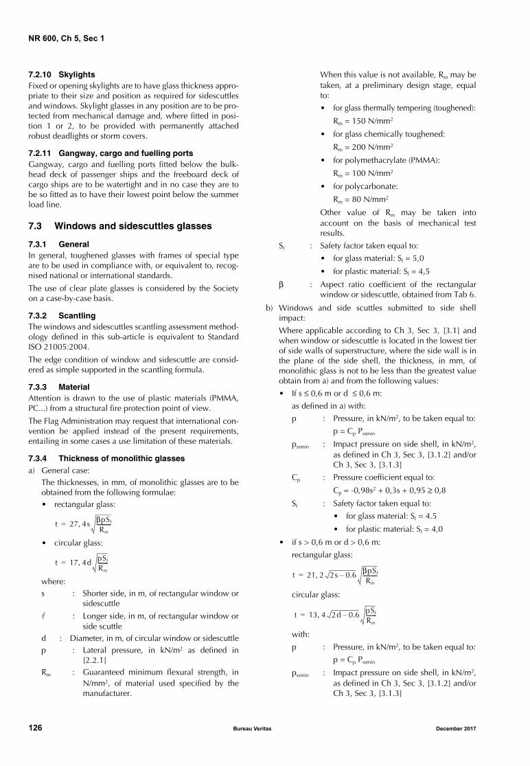
NR 600, Ch 5, Sec 1
7.2.10 SkylightsFixed or opening skylights are to have glass thickness appro-priate to their size and position as required for sidescuttlesand windows. Skylight glasses in any position are to be pro-tected from mechanical damage and, where fitted in posi-tion 1 or 2, to be provided with permanently attachedrobust deadlights or storm covers.
7.2.11 Gangway, cargo and fuelling portsGangway, cargo and fuelling ports fitted below the bulk-head deck of passenger ships and the freeboard deck ofcargo ships are to be watertight and in no case they are tobe so fitted as to have their lowest point below the summerload line.
7.3 Windows and sidescuttles glasses
7.3.1 GeneralIn general, toughened glasses with frames of special typeare to be used in compliance with, or equivalent to, recog-nised national or international standards.
The use of clear plate glasses is considered by the Societyon a case-by-case basis.
7.3.2 ScantlingThe windows and sidescuttles scantling assessment method-ology defined in this sub-article is equivalent to StandardISO 21005:2004.
The edge condition of window and sidescuttle are consid-ered as simple supported in the scantling formula.
7.3.3 MaterialAttention is drawn to the use of plastic materials (PMMA,PC...) from a structural fire protection point of view.
The Flag Administration may request that international con-vention be applied instead of the present requirements,entailing in some cases a use limitation of these materials.
7.3.4 Thickness of monolithic glassesa) General case:
The thicknesses, in mm, of monolithic glasses are to beobtained from the following formulae:• rectangular glass:
• circular glass:
where:s : Shorter side, in m, of rectangular window or
sidescuttle
: Longer side, in m, of rectangular window orside scuttle
d : Diameter, in m, of circular window or sidescuttlep : Lateral pressure, in kN/m2 as defined in
[2.2.1]Rm : Guaranteed minimum flexural strength, in
N/mm2, of material used specified by themanufacturer.
When this value is not available, Rm may betaken, at a preliminary design stage, equalto:
• for glass thermally tempering (toughened):
Rm = 150 N/mm2
• for glass chemically toughened:
Rm = 200 N/mm2
• for polymethacrylate (PMMA):
Rm = 100 N/mm2
• for polycarbonate:
Rm = 80 N/mm2
Other value of Rm may be taken intoaccount on the basis of mechanical testresults.
Sf : Safety factor taken equal to:
• for glass material: Sf = 5,0
• for plastic material: Sf = 4,5
β : Aspect ratio coefficient of the rectangularwindow or sidescuttle, obtained from Tab 6.
b) Windows and side scuttles submitted to side shellimpact:
Where applicable according to Ch 3, Sec 3, [3.1] andwhen window or sidescuttle is located in the lowest tierof side walls of superstructure, where the side wall is inthe plane of the side shell, the thickness, in mm, ofmonolithic glass is not to be less than the greatest valueobtain from a) and from the following values:
• If s ≤ 0,6 m or d ≤ 0,6 m:
as defined in a) with:
p : Pressure, in kN/m2, to be taken equal to:
p = Cp Pssmin
pssmin : Impact pressure on side shell, in kN/m2,as defined in Ch 3, Sec 3, [3.1.2] and/orCh 3, Sec 3, [3.1.3]
Cp : Pressure coefficient equal to:
Cp = -0,98s2 + 0,3s + 0,95 ≥ 0,8
Sf : Safety factor taken equal to:
• for glass material: Sf = 4.5
• for plastic material: Sf = 4,0
• if s > 0,6 m or d > 0,6 m:
rectangular glass:
circular glass:
with:
p : Pressure, in kN/m2, to be taken equal to:
p = Cp Pssmin
pssmin : Impact pressure on side shell, in kN/m2,as defined in Ch 3, Sec 3, [3.1.2] and/orCh 3, Sec 3, [3.1.3]
t 27 4s βpSf
Rm
-----------,=
t 17 4d pSf
Rm
--------,=t 21 2 2s 0.6– βpSf
Rm
-----------,=
t 13 4 2d 0.6– pSf
Rm
--------,=
126 Bureau Veritas December 2017

NR 600, Ch 5, Sec 1
Cp : Pressure coefficient equal to:
Cp = -0,98s2 + 0,3s + 0,95 ≥ 0,8
Sf : Safety factor taken equal to:
• for glass material: Sf = 4.5
• for plastic material: Sf = 4,0
Table 6 : Coefficient β
7.3.5 Thickness of laminated glassesLaminated glass are glass realized by placing a layer of resin(polyvinyl butyral as a general rule) between two sheets ofglass.
The thickness of laminated glasses is to be calculated asdefined in [7.3.4], considering the total thickness of thelaminated glass as a monolithic glass.
7.3.6 Thickness of double glassesDouble glasses are glasses realized by two sheets of glass,separated by a spacebar hermetically sealed.
The thickness of the outside glass exposed to loads is to becalculated as defined in [7.3.4].
7.3.7 Thickness of glasses forming screen bulkheads or internal boundaries of deckhouses
The thickness of glasses forming screen bulkheads on theside of enclosed promenade spaces and that for rectangularwindows in the internal boundaries of deckhouses whichare protected by such screen bulkheads are considered bythe Society on a case-by-case basis.
The Society may require both limitations on the size of rec-tangular windows and the use of glasses of increased thick-ness in way of front bulkheads which are particularlyexposed to heavy sea.
7.4 Deadlight arrangement glasses
7.4.1 GeneralSidescuttles to the following spaces are to be fitted with effi-cient hinged inside deadlights:
• spaces below the freeboard deck
• spaces within the first tier of enclosed superstructures
• first tier deckhouses on the freeboard deck protectingopenings leading below or considered buoyant in stabil-ity calculations.
Deadlights are to be capable of being closed and securedwatertight if fitted below the freeboard deck and weather-tight if fitted above.
7.4.2 Watertight deadlights
Efficient hinged inside deadlights, so arranged that they canbe easily and effectively closed and secured watertight, areto be fitted to all sidescuttles except that, abaft one eighth ofthe ship's length from the forward perpendicular and abovea line drawn parallel to the bulkhead deck at side and hav-ing its lowest point at a height of (3,7 + 0,025 B) m abovethe deepest subdivision summer load line, the deadlightsmay be portable in passenger accommodation other thanthat for steerage passengers, unless the deadlights arerequired by the International Convention on Load Lines inforce to be permanently attached in their proper positions.Such portable deadlights are to be stowed adjacent to thesidescuttles they serve.
7.4.3 Openings at the side shell in the second tier
Sidescuttles and windows at the side shell in the secondtier, protecting direct access below or considered buoyantin the stability calculations, are to be provided with effi-cient, hinged inside deadlights capable of being effectivelyclosed and secured weathertight.
7.4.4 Openings set inboard in the second tier
Sidescuttles and windows set inboard from the side shell inthe second tier, protecting direct access below to spaceslisted in [7.4.1], are to be provided with either efficient,hinged inside deadlights or, where they are accessible, per-manently attached external storm covers of approveddesign and substantial construction capable of being effec-tively closed and secured weathertight.
Cabin bulkheads and doors in the second tier separatingsidescuttles and windows from a direct access leadingbelow may be accepted in place of fitted deadlights orstorm covers.
Note 1: Deadlights in accordance with recognised standards arefitted to the inside of windows and sidescuttles, while storm coversof comparable specifications to deadlights are fitted to the outsideof windows, where accessible, and may be hinged or portable.
7.4.5 Deckhouses on superstructures of less than standard height
Deckhouses situated on a raised quarterdeck or on a super-structure of less than standard height may be treated asbeing on the second tier as far as the provision of deadlightsis concerned, provided the height of the raised quarterdeckor superstructure is not less than the standard quarterdeckheight.
7.4.6 Openings protected by a deckhouse
Where an opening in a superstructure deck or in the top ofa deckhouse on the freeboard deck which gives access to aspace below the freeboard deck or to a space within anenclosed superstructure is protected by a deckhouse, then itis considered that only those sidescuttles fitted in spaceswhich give direct access to an open stairway need to be fit-ted with deadlights.
/s β
1,0 0,284
1,5 0,475
2,0 0,608
2,5 0,684
3,0 0,716
3,5 0,734
≥ 4,0 0,750
December 2017 Bureau Veritas 127
NR 600, Ch 5, Sec 2
SECTION 2 OTHER STRUCTURES
Symbols
LWL : Length at waterline at full load, in m
T : Draught, at full load displacement, in m, asdefined in Ch 1, Sec 1, [4.5]
k : Material factor defined in Ch 1, Sec 2, [2.1.5]for steel, and in Ch 1, Sec 2, [3.1.3] for alumin-ium.
1 Fore part structure
1.1 General
1.1.1 ApplicationThe requirements of this Article apply for the scantling andthe structure arrangement of structures located forward ofthe collision bulkhead for steel and aluminium structure.
Fore part of composite hull structure is to be examinedaccording to NR546 Composite Ships.
1.1.2 ScantlingsThe scantlings of the fore part structure and the flat bottomarea are to be checked as defined in Chapter 4.
Adequate tapering is to be ensured between the structure inthe fore part and the structure aft of the collision bulkhead.
Fore peak structures which form the boundary of spaces notintended to carry liquids, and which do not belong to theouter shell, are to be subjected to lateral pressure in flood-ing conditions. Their scantlings are to be determined asdefined in Chapter 4.
As a rule, secondary and primary stiffeners on side shell areto be calculated according to Ch 4, Sec 4, taking intoaccount a connection with surrounding structure in simplysupported end conditions (m = 8 in the section modulus for-mulae).
1.2 Stems
1.2.1 GeneralAdequate continuity of strength is to be ensured at the con-nection of stems and surrounding structure. Abrupt changesin sections are to be avoided.
1.2.2 Bar stemsThe cross-sectional area, in cm2, of bar stems built offorged, rolled or casting steel or aluminium is to be not lessthan:
• for steel structure:
with 0,05 < T/LWL < 0,075
• for aluminium structure:
with 0,05 < T/LWL < 0,075
The thickness of the bar stem, in mm, is to be not less than:
• for stem in steel:
t = (0,40 LWL + 13) k0,5
• for stem in aluminium:
t = (0,55 LWL + 18) k0,5
The cross-sectional area of the stem may be graduallytapered from the load waterline to the upper end, where itmay be equal to the two thirds of the value as calculatedabove.
The lower part of the stem may be constructed of cast steelor aluminium alloy casting subject to the examination bythe Society. Where necessary, a vertical web is to be fittedfor welding of the centre keelson.
The bar stem is to be welded to the bar keel generally withbutt welding.
The shell plating is also to be welded directly to the barstem with butt welding.
1.2.3 Plate stemsWhere the stem is constructed of shaped plates, the thicknessof the plates below the load waterline is to be not less thanthe value obtained, in mm, from the following formulae:
• for steel structure:
• for aluminium structure:
Above the load waterline, this thickness may be gradu-ally tapered towards the stem head, where it is to be notless than that required for side plating at ends.
As a rule, the expanded width of the stem, in m, is not to beless than:
The plating forming the stems is to be supported by horizon-tal diaphragms spaced about 1000 mm apart and con-nected, as far as practicable, to the adjacent frames and sidestringers.
If considered necessary, and particularly where the stemradius is large, a centreline stiffener or web of suitablescantlings is to be fitted.
Ap 0 40, 10 TLWL
--------+ 0 009L2, 20+( )k0 5,=
Ap 0 40, 10 TLWL
--------+ 0 0125L2, 28+( )k0 5,=
tS 1 37 0 95, LWL+( )k0 5,,=
tS 1 90 0 95, LWL+( )k0 5,,=
b 0 8, 0 5LWL
100----------,+=
128 Bureau Veritas December 2017
NR 600, Ch 5, Sec 2
1.3 Reinforcements of the flat bottom forward area
1.3.1 General
In addition to the requirements in [1.1], the structures of theflat bottom forward area are to be able to sustain thedynamic pressures due to the bottom impact where applica-ble as defined in Ch 3, Sec 3, [3.2.1].
1.3.2 Scantlings
The area defined in Ch 3, Sec 3, [3.2.2] is to be reinforcedas defined below:
a) Plating and secondary stiffeners
The scantlings of plating and secondary stiffeners are tobe not less than the values obtained in Ch 4, Sec 3,[2.2.2] and Ch 4, Sec 4, [2.2.2], taking into account thebottom impact pressure pBi defined in Ch 3, Sec 3,[3.2.3].
b) Primary stiffener structure
As a rule, primary structure is to be checked throughdirect calculation considering a pressure of 0,3 pBi ,where pBi is the bottom impact pressure defined in Ch 3,Sec 3, [3.2.3].
c) Tapering
Outside the flat bottom forward area, scantlings are tobe gradually tapered so as to reach the values requiredfor the areas considered.
1.4 Bow flare
1.4.1 General
a) Bow flare structure
The bow flare area is the area extending forward of0,9 LWL from the aft end of LWL and above the summerload waterline up to the level at which a knuckle withan angle greater than 15° is located on the side shell.
The bow flare structure is to be checked as defined inChapter 4 taking into account the external pressuredefined in Ch 3, Sec 3.
In addition, primary supporting members are generallyto be checked through direct calculations.
When deemed necessary by the Society, the bow impactpressures to take into account for the structure checkaccording to Chapter 4 may be taken equal to the valuesdefined in NR467 Steel Ships, Pt B, Ch 8, Sec 1, [4].
Note 1: As a rule, this bow impact pressure may be taken intoaccount for ship greater than 40 m having a value of angle βgreater than 25°, where β is the angle between a longitudinalline parallel to the centerline of the ship and the tangent to theshell plating in a horizontal plane.
b) Bow flare arrangement
Outside the bow flare area, scantlings are to be gradu-ally tapered so as to reach the values required for theareas considered.
Intercostal stiffeners are to be fitted at mid-span wherethe angle between the stiffener web and the attachedplating is less than 70°.
1.5 Bulbous bow
1.5.1 General
The thickness of the shell plating of the fore end of the bulband the first strake above the keel is generally to be not lessthan that required for the stems.
The structure arrangement of the bulbous bow is to be asdefined in NR467 Steel Ships, Ch 8, Sec 1, [2.11].
1.6 Thruster tunnel
1.6.1 Scantling of the thruster tunnel and connection with the hull
The thickness of the tunnel is to be not less than that of theadjacent hull plating.
When the tunnel is not welded to the hull, the connectiondevices are examined by the Society on a case-by-casebasis.
2 Aft part structure
2.1 General
2.1.1 Application
The requirements of this Article apply for the scantlings ofstructures located aft of the after peak bulkhead and for thereinforcements of the flat bottom aft area for steel and alu-minium structure.
Aft part of composite hull structure are to be examinedaccording to NR546 Composite Ships.
2.1.2 Scantling
The scantling of the aft part structure is to be checked asdefined in Chapter 4.
Adequate tapering is to be ensured between the scantlingsin the aft part and those fore of the after peak bulkhead. Thetapering is to be such that the scantling requirements forboth areas are fulfilled.
Aft peak structures which form the boundary of spaces notintended to carry liquids, and which do not belong to theouter shell, are to be subjected to lateral pressure in flood-ing conditions. Their scantlings are to be determined asdefined in Chapter 4.
As a rule, the minimum thicknesses, in mm, of the followingstructure elements of ship built in steel materials or in alu-minium alloys are to be not less than:
• for bottom and side plating:
• for inner bottom plating:
• for strength deck plating:
• for platform and swash bulkhead:
t 0 03LWL, 5 5,+( )k1 2⁄=
t 3 0 017LWLk1 2⁄, 4 5s,+ +=
t 2 3, 0 013LWLk1 2⁄, 4 5s,+ +=
t 2 3, 0 004LWLk1 2⁄, 4 5s,+ +=
December 2017 Bureau Veritas 129
NR 600, Ch 5, Sec 2
• for web of secondary stiffeners, the lesser of:
-
- the thickness of the attached plating
where:
s : Spacing, in m, of secondary stiffeners or pri-mary supporting members, as applicable.
2.2 After peak
2.2.1 Arrangement
The arrangement of transversely framed after peak structure isto be as defined in NR467 Steel Ships, Pt B, Ch 8, Sec 2, [3].
2.3 Other structures
2.3.1 Connection of hull structures with the rudder horn
The connection of hull structure with the rudder horn is tobe as defined in NR467 Steel Ships, Pt B, Ch 8, Sec 2, [5].
2.3.2 Sternframes
Sternframes scantling, arrangement and connection to thehull are to be as defined in NR467 Steel Ships, Pt B, Ch 8,Sec 2, [6].
3 Machinery spaces
3.1 Application
3.1.1 The requirements of this Article apply for:
• the arrangement of machinery space for ships built insteel, aluminium and composite materials
• the scantling of machinery space structures as regardsgeneral strength for ships built in steel and aluminium.
It is no substitute to machinery manufacturer’s requirementswhich have to be dealt with at Shipyard diligence.
The Designer may propose arrangements and scantlingsalternative to the requirements of this Article, on the basis ofdirect calculations which are to be submitted to the Societyfor examination on a case-by-case basis.
The Society may also require such direct calculations to becarried out whenever deemed necessary.
3.2 General
3.2.1 Unless otherwise specified in this Article, the scantlingof platings and stiffeners in the machinery space are to bedetermined according to the relevant criteria in Chapter 4, asapplicable. In addition, specific requirements specified inthis Section apply.
3.2.2 The structural continuity of the machinery space withhull structures located aft and forward is to be as defined inCh 2, Sec 1.
3.2.3 Machinery space openings and access doors to cas-ings are to be in accordance with:
• NR467 Steel Ships for ships of 500 GT and over and forall ships having the service notation passenger ship, ro-ro passenger ship, fishing vessel or chemical tanker
• NR566 for the other ships.
3.3 Double bottom
3.3.1 General
The general double bottom arrangement is to be as definedin Ch 2, Sec 1, [3].
Access arrangement is to be as defined in Ch 2, Sec 2, [5.2].However, the number and size of manholes in floorslocated in way of seatings and adjacent areas are to be keptto the minimum necessary for double bottom access andmaintenance.
3.3.2 Primary structure scantling
The scantling of double bottom primary structure, for steeland aluminium alloys, is to be as defined in Ch 4, Sec 5. Inaddition, the thickness t, in mm, of floor and girder webs isto be not less than:
t = 5 + 0,045 L k1/2
3.3.3 Double bottom girders
In the machinery space the number of side bottom girders isto be adequately increased, with respect to the adjacentareas, to ensure adequate rigidity of the structure.
The side bottom girders are to be a continuation of any bot-tom longitudinal in the areas adjacent to the machineryspace and are generally to have a spacing not greater than3 times that of longitudinal and in no case greater than 3 m.
Additional side bottom girders are to be fitted in way ofmachinery seatings.
Side bottom girders arranged in way of main machineryseatings are to extend for the full length of the machineryspace.
Where the machinery space is situated amidships, the bot-tom girders are to extend aft of the after bulkhead of suchspace for at least three frame spaces, and beyond to be con-nected to the hull structure by tapering.
Where the machinery space is situated aft, the bottom gird-ers are to extend as far aft as practicable in relation to theshape of the bottom and to be supported by floors and sideprimary supporting members at the ends.
3.3.4 Double bottom floors
As a rule, floors are to be fitted in way of machinery.
3.4 Single bottom
3.4.1 General
The general single bottom arrangement is to be as definedin Ch 2, Sec 1, [3].
Furthermore, additional floors are to be fitted in way ofimportant machinery.
t 1 5LWL1 3⁄ K1 6⁄, 1+=
130 Bureau Veritas December 2017
NR 600, Ch 5, Sec 2
As a rule, floors and girders are to be fitted with welded faceplates in the engine room and especially in way of:• engine bed plates• thrust blocks• auxiliary seatings.
3.4.2 Primary structure scantlingThe scantling of single bottom primary structure, for steeland aluminium alloys, is to be as defined in Ch 4, Sec 5. Inaddition, the thickness t, in mm, of floor and girder webs isto be not less than:
t = 5 + 0,045 L k1/2
3.5 Side
3.5.1 ArrangementThe type of side framing in machinery spaces is generally tobe the same as adopted in the adjacent areas.
When it is not the case, the structural continuity of themachinery side with surrounding structures located aft andforward is to be as defined in Ch 2, Sec 1, and abrupt struc-tural discontinuities between longitudinally and trans-versely framed structure are to be avoided.
3.6 Platforms
3.6.1 The location and extension of platforms in machineryspaces are to be arranged so as to be a continuation of thestructure of side longitudinals, as well as of platforms andside girders located in the adjacent hull areas.In general, platform transverses are to be arranged in way ofside or longitudinal bulkhead transverses.
3.7 Pillaring
3.7.1 Pillars are generally to be arranged in way of:• machinery casing corners and corners of large openings
on platforms; alternatively, two pillars may be fitted onthe centreline (one at each end of the opening)
• the intersection of platform transverses and girders• transverse and longitudinal bulkheads of the superstruc-
ture.
In general, pillars are to be fitted with brackets at their ends.
3.7.2 Pillar bulkhead scantlings are to be not less thanthose required in [3.8] for machinery casing bulkheads.
3.8 Machinery casing
3.8.1 The scantlings of plating and stiffeners are to be notless than those obtained according to the applicablerequirements in Chapter 4.Casings are to be reinforced at the ends by deck beams andgirder associated to pillars.
3.9 Seatings of main engines
3.9.1 GeneralThe scantling of seatings of main engines and thrust bear-ings are to be adequate in relation to the weight and power
of engines and the static and dynamic forces transmitted bythe propulsive installation.
Transverse and longitudinal members supporting the seat-ings are to be located in line with floors and bottom girders.
They are to be so arranged as to avoid discontinuity andensure sufficient accessibility for welding of joints and forsurveys and maintenance.
Seatings are to be adequately connected to floors and gird-ers with flanged brackets.
3.9.2 ScantlingThe scantlings of the structural elements in way of the seat-ings of engines are to be determined by the engine manu-facturer. They are to be checked on the basis of justificativecalculations supplied by the engine manufacturer.
4 Side shell and bulkhead doors
4.1 General
4.1.1 ApplicationThe requirements of this article apply to the scantling ofshell doors and doors in bulkheads that are required to bewatertight or weathertight.
4.1.2 Door scantlingsDoor scantlings are to be designed to offer equivalentstrength compared to the adjacent side shell or bulkhead inwhich they are fitted and are to be examined taking intoaccount the same design loads.
As a rule, the door stiffeners are generally to be consideredas simply supported.
4.1.3 Securing and supporting structureSecuring arrangement and supporting structure are to be asdefined in NR467 Steel Ships, Pt B, Ch 8, Sec 12 [4], takinginto account the permissible local stresses defined inCh 2,Sec 3, Tab 4.
4.1.4 Inspection and testingThe requirements of NR467 Steel Ships, Pt B, Ch 8, Sec 12[5] are applicable.
4.1.5 Type approval procedureThe requirements of NR467 Steel Ships, Pt B, Ch 8, Sec 12[6] are applicable.
5 Bow doors and inner doors
5.1 General
5.1.1 ApplicationThe requirements of this Article apply to the arrangement,strength and securing of bow doors and inner doors leadingto a complete or long forward enclosed superstructure or toa long non-enclosed superstructure, where fitted to attainminimum bow height equivalence.
The requirements apply to ships engaged on internationalvoyages and also to ships engaged only in domestic (noninternational) voyages, except where specifically indicatedotherwise in this Article.
December 2017 Bureau Veritas 131
NR 600, Ch 5, Sec 2
5.1.2 Type of bow doorsThe type of bow door considered in the present article are:
• visor doors opened by rotating upwards and outwardsabout an horizontal axis through two or more hingeslocated near the top of the door and connected to theprimary supporting members of the door by longitudi-nally arranged lifting arms
• side-opening doors opened either by rotating outwardsabout a vertical axis through two or more hinges locatednear the outboard edges or by horizontal translation bymeans of linking arms arranged with pivoted attach-ments to the door and the ship. It is anticipated thatside-opening bow doors are arranged in pairs.
Other types of bow door are considered by the Society on acase by case basis in association with the applicablerequirements of this Section.
5.2 Scantling and arrangement
5.2.1 The scantling of the plating and the secondary stiffen-ers of bow doors are to be checked as defined in Chapter 4for the fore part of the hull.
5.2.2 Primary supporting members, securing and supporting devices
The primary supporting members, securing and supportingdevices of bow doors and inner doors are to be checkedaccording to the following design loads:
• For bow door: greater value between loads defined inCh 3, Sec 3, [2.2.1] and in NR467 Steel Ships, Pt B, Ch8, Sec 5 [2.1]
• For inner door: loads defined in NR467 Steel Ships, Pt B,Ch 8, Sec 5 [2.2]
Scantlings of primary supporting members are generally tobe verified through direct calculations taking into account:
a) Steel structure:
Scantling criteria defined in NR467 Steel Ships, Pt B, Ch 8,Sec 5 [6].
b) Aluminium structure:
For structures built in aluminium alloys, it is to bechecked that the normal stresses σ, the shear stress τand the equivalent stress σVM , induced in the primarysupporting members and in the securing and supportingdevices of bow doors are in compliance with the fol-lowing conditions:
σ ≤ σALL
τ ≤ τALL
σVM = (σ2 + 3 τ2) 0,5 ≤ σVM,ALL
where:
σALL : Allowable normal stress, in N/mm2, equal to:
σALL = 50 / k
τALL : Allowable shear stress, in N/mm2, equal to:
τALL = 35 / k
σVM,ALL : Allowable equivalent stress, in N/mm2,equal to:
σVM,ALL = 65 / k
c) Composite structure:
For composite structure, it is to be checked that thescantling criteria defined in Ch 2, Sec 3, [3.2.1] are ful-filled, where the Rules safety factors SF and SFCS are tobe increased by 60%.
5.3 Securing and locking arrangement
5.3.1 The securing and locking arrangement are to be asdefined in NR467 Steel Ships, Pt B, Ch 8, Sec 5, [7].
5.4 Operating and Maintenance Manual
5.4.1 An Operating and Maintenance Manual for the bowdoor and inner door is to be provided on board and is tocontain the necessary information defined in NR467 SteelShips, Pt B, Ch 8, Sec 5, [8].
6 Side doors and stern doors for Ro-Ro ships
6.1 General
6.1.1 Application
The requirements of this Article apply to the arrangement,strength and securing of side doors located abaft the colli-sion bulkhead, and of stern doors leading to enclosedspaces.
The requirements apply to ships assigned with the servicenotation ro-ro passenger ship or ro-ro cargo ship engagedon international voyages and also in domestic (non-interna-tional) voyages, except where specifically indicated other-wise in this article.
6.2 Scantling and arrangement
6.2.1 Arrangement
Side doors and stern door arrangements are to be as definedin NR467 Steel Ships, Pt B, Ch 8, Sec 6 [1.3].
6.2.2 The scantling of the plating and the secondary stiffen-ers of the side doors and stern doors are to be checked asdefined in Chapter 4 for side hull.
Where doors also serve as vehicle ramps, the thickness ofthe door plating and the scantling of the secondary stiffen-ers are to be as defined in Chapter 4 under wheeled loads.
The primary supporting members are to be checked accord-ing to:
• NR467 Steel Ships, Pt B, Ch 8, Sec 6, [2.1.1] for designexternal forces
• NR467 Steel Ships, Pt B, Ch 8, Sec 6, [5] for strengthcriteria.
For aluminium alloy or composite structure, the primarysupporting members are to be checked according criteriadefined in [5.2.2] b) and c) respectively.
132 Bureau Veritas December 2017
NR 600, Ch 5, Sec 2
6.3 Securing, supporting of doors and lock-ing arrangement
6.3.1 Securing, supporting of doors and locking arrange-ment are to be as defined in NR467 Steel Ships, Pt B, Ch 8,Sec 6, [4] and [6].
6.4 Operating and Maintenance Manual
6.4.1 An Operating and Maintenance Manual for the sidedoors and stern doors is to be provided on board and is tocontain the necessary information defined in NR467 SteelShips, Pt B, Ch 8, Sec 6, [7].
7 Hatch covers
7.1 Small hatch covers
7.1.1 DefinitionSmall hatches are hatches designed for access to spacesbelow the deck and are capable to be closed weathertightor watertight, as applicable. Their opening is generally lessthan or equal to 2,5 m2.
7.1.2 ScantlingThe scantling of plating and stiffeners of hatch coamingsand hatch covers are to be not less than that of the adjacentdeck structure, calculated according to Chapter 4, based onthe same spacing.
7.1.3 ArrangementsThe arrangement of access, height of coamings, securingand closing devices is to be as defined in NR467 Steel Ship,Pt B, Ch 8, Sec 8.
7.2 Large hatch covers
7.2.1 DefinitionLarge hatches are hatches with openings greater than2,5 m2.
7.2.2 GeneralThe requirements of the present sub-article apply for thescantling and the arrangement of large hatch covers andhatch coamings of stiffened plate construction and its clos-ing arrangements built in steel.
The arrangement of hatch covers built in other materials areexamined by the Society on a case-by-case basis.
7.2.3 Scantling and arrangementExcepted where specified in [7.2.5], the scantling and thearrangement of hatch covers and hatch coamings are exam-ined on a case-by-case basis, based on the requirementsdefined in NR467 Steel Ships, Pt B, Ch 8, Sec 7.
7.2.4 Buckling strength of hatch coamingsWhen the hatch coamings contribute to the longitudinalhull girder strength, the buckling strength assessment ofcoaming parts is to be carried out according to Ch 4, Sec 2.
7.2.5 The scantling and the arrangement of hatch coversand hatch coamings for ship having the service notation
bulk carrier, ore carrier and combination carrier are to beas defined in NR467 Steel Ships, Pt D, Ch 4, Sec 4.
8 Movable decks, inner ramps and external ramps
8.1 Application
8.1.1 The requirements of this Article apply to movabledecks and inner ramps when the additional class notationALP is not granted and when no cargo gear register isissued.
8.1.2 On special request of the owner the movable innerramps under load may be examined by the Society in thescope of the application of NR526 Rules for the Certifica-tion of Lifting Appliances on board Ships and OffshoreUnits and the assignment of additional class notation ALP(see NR467 Steel Ships, Pt A, Ch 1, Sec 2).
8.2 Scantling
8.2.1 MaterialsThe movable decks and inner ramps are to be made of steelor aluminium alloys complying with the requirements ofNR216 Materials and Welding. Other materials of equiva-lent strength may be used, subject to a case-by-case exami-nation by the Society.
8.2.2 Plating and secondary stiffener scantlingThe thickness of plate panels and the section modulus andshear sectional area of secondary stiffeners subjected towheeled loads are to be not less than the value obtainedfrom Ch 4, Sec 3 and Ch 4, Sec 4, as applicable, with avalue of Fw ⋅ n (or Fw for secondary stiffeners) to be taken notless than 5 kN, where:
Fw : Wheeled force, in kN, as defined in Ch 3, Sec 4,[3.3]
n : Number of wheels on the plate panel as definedin Ch 4, Sec 3, [2.2.4].
8.3 Primary supporting members
8.3.1 GeneralThe supporting structure of movable decks and inner rampsis to be examined through direct calculation, consideringthe following cases:
• movable deck stowed in upper position, empty andlocked, at sea
• movable deck in service, loaded, in lower position, rest-ing on supports or supporting legs and locked, at sea
• movable inner ramp in sloped position, supported byhinges at one end and by a deck at the other, with possi-ble intermediate supports, loaded, at harbour
• movable inner ramp in horizontal position, loaded andlocked, at sea.
8.3.2 Loading casesThe scantlings of the structure are to be checked in both seaand harbour conditions for the following cases:
December 2017 Bureau Veritas 133
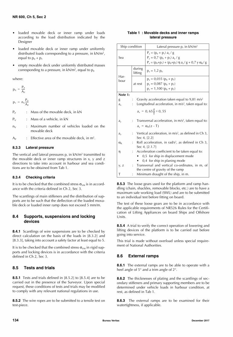
NR 600, Ch 5, Sec 2
• loaded movable deck or inner ramp under loadsaccording to the load distribution indicated by theDesigner
• loaded movable deck or inner ramp under uniformlydistributed loads corresponding to a pressure, in kN/m2,equal to p0 + p1
• empty movable deck under uniformly distributed massescorresponding to a pressure, in kN/m2, equal to p0
where:
PP : Mass of the movable deck, in kN
PV : Mass of a vehicle, in kN
nV : Maximum number of vehicles loaded on themovable deck
AP : Effective area of the movable deck, in m2.
8.3.3 Lateral pressure
The vertical and lateral pressures p, in kN/m2 transmitted tothe movable deck or inner ramp structures in x, y and zdirections to take into account in harbour and sea condi-tions are to be obtained from Tab 1.
8.3.4 Checking criteria
It is to be checked that the combined stress σVM is in accord-ance with the criteria defined in Ch 2, Sec 3.
The scantlings of main stiffeners and the distribution of sup-ports are to be such that the deflection of the loaded mova-ble deck or loaded inner ramp does not exceed 5 mm/m.
8.4 Supports, suspensions and locking devices
8.4.1 Scantlings of wire suspensions are to be checked bydirect calculation on the basis of the loads in [8.3.2] and[8.3.3], taking into account a safety factor at least equal to 5.
It is to be checked that the combined stress σVM in rigid sup-ports and locking devices is in accordance with the criteriadefined in Ch 2, Sec 3.
8.5 Tests and trials
8.5.1 Tests and trials defined in [8.5.2] to [8.5.4] are to becarried out in the presence of the Surveyor. Upon specialrequest, these conditions of tests and trials may be modifiedto comply with any relevant national regulations in use.
8.5.2 The wire ropes are to be submitted to a tensile test ontest-piece.
Table 1 : Movable decks and inner rampslateral pressure
8.5.3 The loose gears used for the platform and ramp han-dling (chain, shackles, removable blocks, etc.) are to have amaximum safe working load (SWL) and are to be submittedto an individual test before fitting on board.
The test of these loose gears are to be in accordance withthe applicable requirements of NR526 Rules for the Certifi-cation of Lifting Appliances on board Ships and OffshoreUnits.
8.5.4 A trial to verify the correct operation of lowering andlifting devices of the platform is to be carried out beforegoing into service.
This trial is made without overload unless special require-ment of National Authorities.
8.6 External ramps
8.6.1 The external ramps are to be able to operate with aheel angle of 5° and a trim angle of 2°.
8.6.2 The thicknesses of plating and the scantlings of sec-ondary stiffeners and primary supporting members are to bedetermined under vehicle loads in harbour condition, atrest, as defined in Tab 1.
8.6.3 The external ramps are to be examined for theirwatertightness, if applicable.
p0PP
AP
------=
p1 nVPV
AP
------=
Ship condition Lateral pressure p, in kN/m2
SeaPx = (p0 + p1) ax / g Py = 0,7 (p0 + p1) ay / g Px = (p0+p1) + (p0+p1) η az / g + 0,7 y αR / g
Har-bour
during lifting
pz = 1,2 p0
at restpx = 0,035 (p0 + p1)py = 0,087 (p0 + p1)pz = 1,100 (p0 + p1)
Note 1:g : Gravity acceleration taken equal to 9,81 m/s2 ax : Longitudinal acceleration, in m/s2, taken equal to:
ay : Transversal acceleration, in m/s2, taken equal to:
az : Vertical acceleration, in m/s2, as defined in Ch 3,Sec 4, [2.2]
αR : Roll acceleration, in rad/s2, as defined in Ch 3,Sec 4, [2.1.7]
η : Acceleration coefficient to be taken equal to:• 0,5 for ship in displacement mode• 0,4 for ship in planing mode
y, z : Transversal and vertical co-ordinates, in m, ofthe centre of gravity of the ramp
T : Minimum draught of the ship, in m.
ax 0 65zT---, 0 55,+=
ay αR z T–( )=
134 Bureau Veritas December 2017
NR 600, Ch 5, Sec 2
8.6.4 The locking of external ramps in stowage position atsea is examined by the Society on a case-by-case basis.
8.6.5 The ship structure under the reactions due to theramp is examined by the Society on a case-by-case basis.
9 Rudders
9.1 General
9.1.1 The scantling of rudders built in steel is to be inaccordance with the requirements defined in NR467 SteelShips, Pt B, Ch 9, Sec 1.For rudder built in aluminium alloys, the material factor k1
to be taken into account in the scantling formulae is to betaken equal to:
where:Ry : Minimum yield stress of aluminium, in N/mm2,
defined in Ch 1, Sec 2, [3.1.2].For planing hull as defined in Ch 1, Sec 1, [2.1.4], theahead service speed to take into account in the ruddercheck is to be taken equal to the minimum value between:• VAV
• 2/3 (VAV + 2 LWL0,5)
where:VAV : Maximum ahead service speed, in knots, at
maximum displacement in steel water.Rudders built in composite materials are to be examined ona case-by-case basis by the Society taking into accountsafety factor criteria defined in Ch 2, Sec 3, [3.1] whereRules safety factors are to be increased by a coefficient tobe taken at least equal to 1,3.
9.2 Rudder horn and solepiece
9.2.1 GeneralArrangement of rudder horn and solepiece are to be inaccordance with NR467 Steel Ships, Pt B, Ch 9, Sec 1.
9.2.2 Rudder horn scantlingThe scantling of rudder horn built in steel is to be as definedin NR467 Steel Ships, Pt B, Ch 9, Sec 1, [8].
For rudder horn in aluminium alloys, the allowable stressesto be taken into account are the following ones:τALL : Allowable shear stress, in N/mm2, equal to:
τALL = 20 / k
σE,ALL : Allowable equivalent stress, in N/mm2, equal to:σE,ALL = 50 / k
σB,ALL : Allowable bending stress, in N/mm2, equal to:σB,ALL = 30 / k
where:k : Material factor for aluminium, defined in Ch 1,
Sec 2, [3.1.3].For ships with notation launch or seagoing launch, theallowable stresses may be increased by 10%.
Rudder horn in composite materials are to be examined ona case-by-case basis by the Society taking into accountsafety factor criteria defined in Ch 2, Sec 3, [3.1] where theRules safety factors are to be increased by a coefficient tobe taken at least equal to:
• for the main stress safety factor: 1,9
• for the combined stress safety factor: 1,3
9.2.3 Solepieces scantlingThe scantling of solepieces built in steel is to be as definedin NR467 Steel Ships, Pt B, Ch 9, Sec 1, [8].
For solepieces in aluminium alloys, the allowable stresses tobe taken into account are the following ones:
σB,ALL : Allowable bending stress, in N/mm2, equal to:
σB,ALL = 35 / k
τALL : Allowable shear stress, in N/mm2, equal to:
τALL = 20 / k
For ships with notation launch or seagoing launch, theallowable stresses may be increased by 10%.
Solepiece in composite materials are to be examined on acase-by-case basis by the Society taking into account safetyfactor criteria defined in Ch 2, Sec 3, [3.1] where the Rulessafety factors are to be increased by a coefficient to betaken at least equal to:
• for the main stress safety factor: 1,9
• for the combined stress safety factor: 1,3
10 Water jet propulsion tunnel
10.1 General
10.1.1 The drawings of water jet duct, ship supportingstructure, thrust bearing, as well as shell openings and localreinforcements are to be submitted for examination.
The pressure in water jet ducts, the forces and momentsinduced by the water jet to the hull structure and the calcu-lation procedure from the Designer are to be specified.
10.1.2 Waterjet supporting structure in steel or aluminium
The supporting structure of waterjets is to be able to with-stand the loads induced by the waterjet in the followingconditions:
• maximum ahead thrust
• maximum thrust at maximum lateral inclination
• maximum reversed thrust (going astern).
Information on the above loads is to be given by the water-jet manufacturer.
For each waterjet, the following loading cases are to beinvestigated:
LDC1 : Internal hydrodynamic pressure ph in the built-in nozzle
LDC2 : Horizontal longitudinal force Fx1 in normal ser-vice (ahead)
LDC3 : Horizontal transverse force Fy and associatedmoment Mz during steering operation
k1235Ry
----------=
December 2017 Bureau Veritas 135
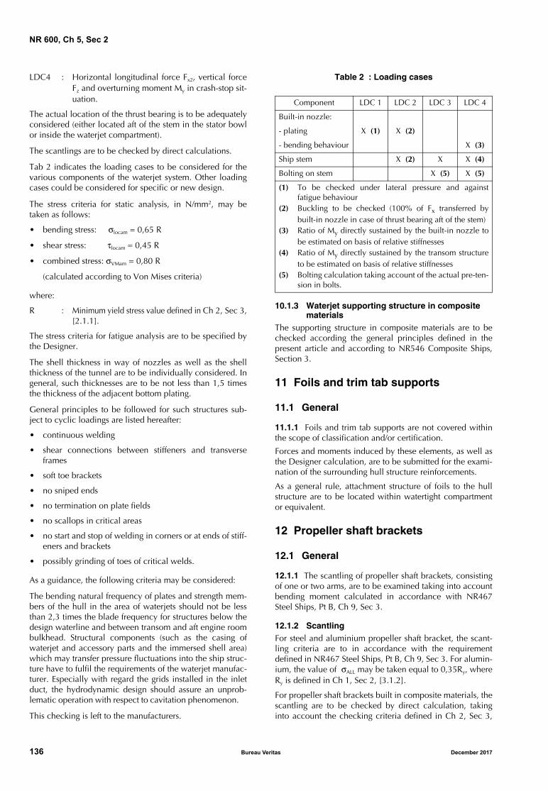
NR 600, Ch 5, Sec 2
LDC4 : Horizontal longitudinal force Fx2, vertical forceFz and overturning moment My in crash-stop sit-uation.
The actual location of the thrust bearing is to be adequatelyconsidered (either located aft of the stem in the stator bowlor inside the waterjet compartment).
The scantlings are to be checked by direct calculations.
Tab 2 indicates the loading cases to be considered for thevarious components of the waterjet system. Other loadingcases could be considered for specific or new design.
The stress criteria for static analysis, in N/mm2, may betaken as follows:
• bending stress: σlocam = 0,65 R
• shear stress: τlocam = 0,45 R
• combined stress: σVMam = 0,80 R
(calculated according to Von Mises criteria)
where:
R : Minimum yield stress value defined in Ch 2, Sec 3,[2.1.1].
The stress criteria for fatigue analysis are to be specified bythe Designer.
The shell thickness in way of nozzles as well as the shellthickness of the tunnel are to be individually considered. Ingeneral, such thicknesses are to be not less than 1,5 timesthe thickness of the adjacent bottom plating.
General principles to be followed for such structures sub-ject to cyclic loadings are listed hereafter:
• continuous welding
• shear connections between stiffeners and transverseframes
• soft toe brackets
• no sniped ends
• no termination on plate fields
• no scallops in critical areas
• no start and stop of welding in corners or at ends of stiff-eners and brackets
• possibly grinding of toes of critical welds.
As a guidance, the following criteria may be considered:
The bending natural frequency of plates and strength mem-bers of the hull in the area of waterjets should not be lessthan 2,3 times the blade frequency for structures below thedesign waterline and between transom and aft engine roombulkhead. Structural components (such as the casing ofwaterjet and accessory parts and the immersed shell area)which may transfer pressure fluctuations into the ship struc-ture have to fulfil the requirements of the waterjet manufac-turer. Especially with regard the grids installed in the inletduct, the hydrodynamic design should assure an unprob-lematic operation with respect to cavitation phenomenon.
This checking is left to the manufacturers.
Table 2 : Loading cases
10.1.3 Waterjet supporting structure in composite materials
The supporting structure in composite materials are to bechecked according the general principles defined in thepresent article and according to NR546 Composite Ships,Section 3.
11 Foils and trim tab supports
11.1 General
11.1.1 Foils and trim tab supports are not covered withinthe scope of classification and/or certification.
Forces and moments induced by these elements, as well asthe Designer calculation, are to be submitted for the exami-nation of the surrounding hull structure reinforcements.
As a general rule, attachment structure of foils to the hullstructure are to be located within watertight compartmentor equivalent.
12 Propeller shaft brackets
12.1 General
12.1.1 The scantling of propeller shaft brackets, consistingof one or two arms, are to be examined taking into accountbending moment calculated in accordance with NR467Steel Ships, Pt B, Ch 9, Sec 3.
12.1.2 ScantlingFor steel and aluminium propeller shaft bracket, the scant-ling criteria are to in accordance with the requirementdefined in NR467 Steel Ships, Pt B, Ch 9, Sec 3. For alumin-ium, the value of σALL may be taken equal to 0,35Ry, whereRy is defined in Ch 1, Sec 2, [3.1.2].
For propeller shaft brackets built in composite materials, thescantling are to be checked by direct calculation, takinginto account the checking criteria defined in Ch 2, Sec 3,
Component LDC 1 LDC 2 LDC 3 LDC 4
Built-in nozzle:
- plating X (1) X (2)
- bending behaviour X (3)
Ship stem X (2) X X (4)
Bolting on stem X (5) X (5)
(1) To be checked under lateral pressure and againstfatigue behaviour
(2) Buckling to be checked (100% of Fx transferred bybuilt-in nozzle in case of thrust bearing aft of the stem)
(3) Ratio of My directly sustained by the built-in nozzle tobe estimated on basis of relative stiffnesses
(4) Ratio of My directly sustained by the transom structureto be estimated on basis of relative stiffnesses
(5) Bolting calculation taking account of the actual pre-ten-sion in bolts.
136 Bureau Veritas December 2017
NR 600, Ch 5, Sec 2
[3.1] where the Rules safety factors are to be increased by acoefficient to be taken at least equal to:
• for the main stress safety factor: 1,8
• for the combined stress safety factor: 1,5
13 Bulwarks and guard rails
13.1 Bulwarks
13.1.1 Arrangement of bulwarksThe general arrangement of bulwarks is to be as defined inNR467 Steel Ships, Pt B, Ch 9, Sec 2.
13.1.2 Scantling of bulwarks
a) Plating and secondary stiffeners
The platings and the secondary stiffeners scantling are tobe as defined in Ch 4, Sec 3, [2] and Ch 4, Sec 4, [2].
b) Stays for steel and aluminium structure:
The section modulus, in cm3, and the shear section, incm2, of stays and their connection to the deck structurein way of the lower part of the bulwark are to be not lessthan the values obtained from the following formulae:
• for section modulus, the greater value obtainedfrom:
and:
- if ≥ 0,6 m and s ≥ 0,6 m:
- if ≥ 0,6 m and s < 0,6 m:
- if < 0,6 m:
with s not taken greater than 0,6 m.
• for shear section, the greater value obtained from:
and:
- if ≥ 0,6 m and s ≥ 0,6 m:
- if ≥ 0,6 m and s < 0,6 m:
- if < 0,6 m:
with s not taken greater than 0,6 m.
where:
ps : Sea pressure on side shell as defined in Ch 3,Sec 3, [2.2.1], in kN/m2, calculated at mid-height of the stay
pssmin : Impact pressure on side shell as defined inCh 3, Sec 3, [3.1], in kN/m2
s : Spacing of stays, in m
: Length of stays, in m
σlocam , τlocam : Permissible stresses as defined in Ch 2,Sec 3.
c) Stays for composite structure:
The stays and their connections to the deck structure areto be examined taking into account the values of bend-ing moments, in kN.m, and shear forces, in kN definedin NR546 Composite Ships, Sec 3, [10.2].
The scantling of the stays are to be examined as definedin NR546 Composite Ships for stiffener analysis, takinginto account the safety factors defined in Ch 2, Sec 3,[3.1].
13.2 Guard rails
13.2.1 The general arrangement and the scantling of guardrails are to be in accordance with the requirements ofNR467 Steel Ships Pt B, Ch 9, Sec 2.
14 Lifting appliances
14.1 General
14.1.1 The fixed parts of lifting appliances and their con-nections to the ship’s structure are covered by the Rules,even when the certification (especially the issuance of theCargo Gear Register) of lifting appliances is not required.
The fixed parts of lifting appliances, considered as an inte-gral part of the hull, are the structures permanently con-nected to the ship’s hull (for instance crane pedestals, masts,king posts, derrick heel seatings, etc., excluding cranes, der-rick booms, ropes, rigging accessories, and, generally, anydismountable parts). The shrouds of masts embedded in theship’s structure are considered as fixed parts.
The foundations of lifting appliances intended to be used atsea are to comply with the requirements of NR608 Classifi-cation of Lifting Units, Section 4.
14.1.2 Checking criteriaThe forces and moments transmitted by the crane to theship structure are to be submitted to the Society.
For crane not used in offshore conditions having a safeworking load F less than 50 kN, and when the deadweightsof the crane are unknown, the bending moment M, inkN⋅m, induced by the crane pedestal to the hull is to betaken equal to:
M = 2,2 F x0
where:
x0 : Maximum jib radius of the crane, in m.
For cranes having a safe working load greater than 50 kN orfor crane used in offshore conditions, the bending momentand forces induced by the crane pedestal to the hull are to
z500pss
2
σlocam
-----------------------=
z280pssmin 0 3,–( )
σlocam
-----------------------------------------------=
z600spssmin 0 3,–( )
σlocam
--------------------------------------------------=
z500pssmins2
σlocam
-------------------------------=
Ash10pssτlocam
-----------------=
Ash2 8pssmin,
τlocam
-----------------------=
Ash6spssmin
τlocam
-------------------=
Ash10pssmins
τlocam
--------------------------=
December 2017 Bureau Veritas 137
NR 600, Ch 5, Sec 2
be as defined in NR526 Rules for the Certification of LiftingAppliances onboard Ships and Offshore Units.
Local reinforcements and hull structure surrounding thecrane pedestal are to be checked by direct calculations, tak-ing into account the following permissible stresses:
a) For steel and aluminium structure:σVMam = 0,63 R
where:σVMam : Combined stress calculated according to
Von Mises criteriaR : Minimum yield stress value defined in Ch 2,
Sec 3, [2.1.1].When inserted plates are provided in deck, side shell orbulkheads in way of crane foundation, these inserts areto have well radiused corners and are to be edge-pre-pared prior to welding.
b) For composite structure:SFCRANE = 1,7 SF
SFCSCRANE = 1,7 SFCS
where:
SF : Rules safety factor applicable to maximumstress defined in Ch 2, Sec 3, [3.2.3]
SFCS : Rules safety factor applicable to combinedstress defined in Ch 2, Sec 3, [3.2.3].
15 Protection of metallic hull
15.1 General
15.1.1 The protection of hull metallic structure is to be asdefined in NR467 Steel Ships, Pt B, Ch 10, Sec 1 andincludes the following types of protection:
• coating
• galvanic corrosion in tanks
• wooden ceiling of double bottom (see Note 1)
• wood sheathing of decks
• batten in cargo side.
Note 1: Wooden ceiling on the inner bottom is not required wherethe thickness of the inner bottom, calculated according to Ch 4,Sec 3, [2], is increased by 2 mm.
138 Bureau Veritas December 2017
NR 600, Ch 5, Sec 3
SECTION 3 HELICOPTER DECKS AND PLATFORMS
Symbols
WH : Maximum weight of the helicopter, in t
g : Gravity acceleration taken equal to 9,81 m/s2.
1 Application
1.1 General
1.1.1 The requirements of this Section apply to areasequipped for the landing and take-off of helicopters withlanding gears or landing skids, and located on a deck or ona platform permanently connected to the hull structure.
1.1.2 Helicopter deck or platform intended for the landingof helicopters having landing devices other than wheels orskids are to be examined by the Society on a case-by-casebasis.
1.2 Definition
1.2.1 Landing gearA landing gear may consist of a single wheel or a group ofwheels.
2 General arrangement
2.1 Landing area and approach sector
2.1.1 The main dimensions of the landing area, its locationon board, the approach sector for landing and take-off areto comply with the applicable requirements from Nationalor other Authorities.
2.1.2 The landing area and the approach sector are to befree of obstructions above the level of the helicopter deck orplatform.Note 1: The following items may exceed the height of the landingarea, but not more than 100 mm:
• guttering or slightly raised kerb
• lightning equipment
• outboard edge of the safety net
• foam monitors
• those handrails and other items associated with the landingarea which are incapable of complete retraction or lowering forhelicopter operations.
2.2 Sheathing of the landing area
2.2.1 Within the landing area, a non-skid deck covering isrecommended.
Where the helicopter deck or platform is wood sheathed,special attention is to be paid to the fire protection.
2.3 Safety net
2.3.1 It is recommended to provide a safety net at the sidesof the helicopter deck or platform.
2.4 Drainage system
2.4.1 Gutterways of adequate height and a drainage systemare recommended on the periphery of the helicopter deckor platform.
2.5 Deck reinforcements
2.5.1 Local deck strengthening is to be fitted at the connec-tion of diagonals and pillars supporting platform.
3 Design loads
3.1 Emergency landing load
3.1.1 The emergency landing force FEL transmitted throughone landing gear or one extremity of skid to the helicopterdeck or platform is to be obtained, in kN, from the follow-ing formulae:
FEL = 1,25 g WH
The points of application of this force are to be taken so as toproduce the most severe load on the supporting structure.
3.2 Garage load
3.2.1 Where a garage zone is fitted in addition to the land-ing area, the local forces FW transmitted by one wheel or agroup of wheels or one skid to the helicopter deck or plat-form are to be obtained, in kN, as specified in Ch 3, Sec 4,[3.3], where M is to be taken equal to:
• for helicopter with landing gears:
M is the landing gear load, in t, to be specified by theDesigner. If the landing gear load is not known, M is tobe taken equal to:
where n is the total number of landing gears
• for helicopter with landing skids:
M = 0,5 WH
M 1 25,n
-------------WH=
December 2017 Bureau Veritas 139
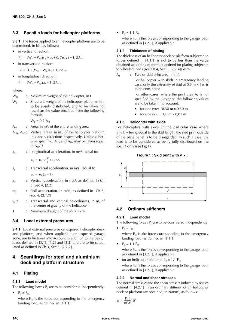
NR 600, Ch 5, Sec 3
3.3 Specific loads for helicopter platforms
3.3.1 The forces applied to an helicopter platform are to bedetermined, in kN, as follows:
• in vertical direction:
• in transverse direction:
• in longitudinal direction:
where:
WH : Maximum weight of the helicopter, in t
Wp : Structural weight of the helicopter platform, in t,to be evenly distributed, and to be taken notless than the value obtained from the followingformula:
Wp = 0,2 AH
AH : Area, in m2, of the entire landing area
AHX, AHY : Vertical areas, in m2, of the helicopter platformin x and y directions respectively. Unless other-wise specified, AHX and AHY may be taken equalto AH / 3
ax : Longitudinal acceleration, in m/s2, equal to:
ay : Transversal acceleration, in m/s2, equal to:
az : Vertical acceleration, in m/s2, as defined in Ch3, Sec 4, [2.2]
αR : Roll acceleration, in m/s2, as defined in Ch 3,Sec 4, [2.1.7]
y, z : Transversal and vertical co-ordinates, in m, ofthe centre of gravity of the helicopter
T : Minimum draught of the ship, in m.
3.4 Local external pressures
3.4.1 Local external pressures on exposed helicopter deckand platform, and when applicable on exposed garagezone, are to be taken into account in addition to the designloads defined in [3.1], [3.2] and [3.3] and are to be calcu-lated as defined in Ch 3, Sec 3, [2.2.2].
4 Scantlings for steel and aluminium deck and platform structure
4.1 Plating
4.1.1 Load modelThe following forces P0 are to be considered independently:
• P0 = FEL
where FEL is the force corresponding to the emergencylanding load, as defined in [3.1.1]
• P0 = 1,1 FW
where FW is the forces corresponding to the garage load,as defined in [3.2.1], if applicable.
4.1.2 Thickness of platingThe thickness of an helicopter deck or platform subjected toforces defined in [4.1.1] is not to be less than the valueobtained according to formula defined for plating subjectedto wheeled loads (see Ch 4, Sec 3, [2.2.4]) with:
AT : Tyre or skid print area, in m2.
For helicopter with skids in emergency landingcase, only the extremity of skid of 0,3 m x 1 m isto be considered.
For other cases, where the print area AT is notspecified by the Designer, the following valuesare to be taken into account:
• for one tyre: 0,30 m x 0,30 m
• for one skid: 1,0 m x 0,01 m
4.1.3 Helicopter with skidsFor helicopters with skids, in the particular case wherev > , v being equal to the skid length, the skid print outsideof the plate panel is to be disregarded. In such a case, theload is to be considered as being fully distributed on thespan only (see Fig 1).
Figure 1 : Skid print with v >
4.2 Ordinary stiffeners
4.2.1 Load modelThe following forces P0 are to be considered independently:
• P0 = FEL
where FEl is the force corresponding to the emergencylanding load, as defined in [3.1.1]
• P0 = 1,1 FW
where FW is the forces corresponding to the garage load,as defined in [3.2.1], if applicable
• for an helicopter platform: P0 = 1,1 FW
where FW is the forces corresponding to the garage load,as defined in [3.2.1], if applicable.
4.2.2 Normal and shear stressesThe normal stress σ and the shear stress τ induced by forcesdefined in [4.2.1] in an ordinary stiffener of an helicopterdeck or platform are obtained, in N/mm2, as follows:
FZ WH WP+( ) g az 0 7αRy,+ +( ) 1 2AHY,+=
FY 0 7 WH Wp+( )ay, 1 2AHY,+=
FX WH Wp+( )ax 1 2AHX,+=
ax 0 65zT---, 0 55,+=
ay αR z T–( )= s
u
v
�
σ P0
mW-----------103=
140 Bureau Veritas December 2017
NR 600, Ch 5, Sec 3
where:
m : Coefficient to be taken equal to:
• for an helicopter with wheels:
m = 6
• for an helicopter with landing skids:
m = 10
4.2.3 Checking criteria
It is to be checked that the normal stress σ and the shearstress τ calculated according to [4.2.2], are in compliancewith the following formulae:
where:
Ry : Minimum yield stress, in N/mm2, of the mate-rial, as defined in:
• for steel structure:
Ch 1, Sec 2, [2.1.5]
• for aluminium structure:
Ch 1, Sec 2, [3.1.2]
4.3 Primary supporting members
4.3.1 Load model
The primary structure check is to be carried out by directcalculation, taking into account the following loads consid-ered independently:
• emergency landing load, as defined in [3.1.1]
• garage load, as defined in [3.2.1], if applicable
• for an helicopter platform, specific loads as defined in[3.3.1].
The most unfavourable case, i.e. where the maximum num-ber of land gears is located on the same primary supportingmembers, is to be considered.
4.3.2 Checking criteria
It is to be checked that the equivalent stress σVM is in com-pliance with the following formula:
where:
Ry : Minimum yield stress, in N/mm2, of the mate-rial, as defined in [4.2.3].
When a two- or three-dimensional beam model calculationor a finite element model calculation is carried out to checkthe primary structure, the permissible stresses in the primarystructure are defined in Ch 2, Sec 3, [2.1.1], b) and in Ch 2,Sec 3, [2.1.1], c), where σVMam is to be taken equal to
0,95 Ry.
5 Scantlings for composite deck structure
5.1 Bending moments and transverse shear forces calculation for deck panel
5.1.1 Bending moments and transverse shear forces in deckpanels are to be calculated taking into account the forcesdefined in [4.1] by direct calculation.
The panel analysis is to be carried out by a “ply by ply”analysis of the laminate taking into account the maximumstress criteria combined stress in each layer criteria asdefined in NR546 Composite Ships, Sec 6 [5.1.2].
5.2 Bending moment and shear forces cal-culation for secondary stiffeners
5.2.1 The bending moment M, in KN.m, and the shearforce T, in KN, induced by forces defined in [4.2.1] in anordinary stiffener of an helicopter deck are obtained, inN/mm2, as follows:
where:
m : Coefficient to be taken equal to:
• for an helicopter with wheels:
m = 6
• for an helicopter with landing skids:
m = 10
The strains and stresses induced by the bending momentand shear force in the secondary stiffener are to be calcu-lated as defined in NR546 Composite Ships, Sec 7 [3.1].
5.3 Primary supporting members
5.3.1 The primary structure check is to be carried out bydirect calculation as defined in [4.3.1].
The strains and stresses induced by the bending momentand shear force in the primary supporting members are tobe calculated as defined in NR546 Composite Ships, Sec 7[3.1].
5.4 Checking criteria
5.4.1 The structure check is to be carried out as defined inNR546 Composite Ships for deck panels and stiffeners, tak-ing into account the safety factors defined for local sea andinternal pressures in Ch 2, Sec 3, [3.2]
τ 10P0
ASh
------------=
0.95Ry σ≥0 45Ry, τ≥
σVM 0.95Ry≤
MP0
m--------=
T P0=
December 2017 Bureau Veritas 141
NR 600, Ch 5, Sec 4
SECTION 4 ANCHORING EQUIPMENT AND SHIPBOARD
FITTINGS FOR ANCHORING, MOORING AND
TOWING EQUIPMENT
Symbols
ReH : Minimum yield stress, in kN/m2, defined in Ch 1,Sec 2, [2]
R’lim : Minimum yield stress, in kN/m2, defined in Ch 1,Sec 2, [2].
1 Design assumption for anchoring equipment
1.1 General
1.1.1 The requirements of the present Section only apply totemporary anchoring of ships within a harbour or shelteredarea, where the ship is awaiting for berth, tide, etc.
1.1.2 The equipment complying with these requirements isnot designed to hold a ship off fully exposed coast in roughweather nor for stopping the ship which is moving or drift-ing. In these conditions, the loads on anchoring equipmentincrease to such a degree that its components can be dam-aged or lost.
1.1.3 For ships where frequent anchoring in open sea isexpected, Owner’s, shipyard’s and Designer’s attention isdrawn to the fact that anchoring equipment should be pro-vided in excess to the requirements of this Rules.
1.1.4 The equipment complying with the requirements in[3] is intended for holding a ship in good holding sea bot-tom, where the conditions are such as to avoid dragging ofthe anchor. In poor holding sea bottom, the holding powerof the anchors is significantly reduced.
1.1.5 Anchors and chains cable components and its accesso-ries, wire rope, etc. are to be manufactured in accordancewith relevant requirements of NR216 Materials and Welding.
1.1.6 The bow anchors, connected to their own chaincables, are to be so stowed as to always be ready for use.Other arrangements of equivalent provision in security andsafety may be foreseen, subjected to Society’s agreement.
1.2 General case
1.2.1 The determination of the anchoring equipment, asstipulated in [2], for ships having the navigation notationunrestricted navigation or coastal area is based on the fol-lowing assumptions:
• wind speed: 50 knots (25 m/s)
• current speed: 5 knots (2,5 m/s)
• the water depth for anchoring is approximately betweenone tenth and one sixth of the chain cable length calcu-lated according to [3.2.2], and
• the ship uses one anchor only under normal circum-stances.
1.3 Specific cases
1.3.1 Ships with navigation notation sheltered area
The determination of the anchoring equipment, as stipu-lated in [2], for ships having the navigation notation shel-tered area is to be based on the following assumptions:
• wind speed: 30 knots (15,5 m/s), and
• current speed: 5 knots (2,5 m/s).
1.3.2 Ships with service notation seagoing launch
The determination of the anchoring equipment, as stipu-lated in [2], for ships having the service notation seagoinglaunch is to be based on the following assumptions:
• wind speed: 27 knots (14 m/s), and
• current speed: 5 knots (2,5 m/s).
Specific arrangements are defined in Ch 6, Sec 1, [17].
1.3.3 Ships with service notation launch
The determination of the anchoring equipment, as stipu-lated in [2] for ships having the service notation launch is tobe based on the following assumptions:
• wind speed: 16 knots (8,5 m/s), and
• current speed: 5 knots (2,5 m/s).
Specific arrangements are defined in Ch 6, Sec 1, [17].
1.3.4 Ships with service notation ro-ro passenger ship or passenger ship
For ships having L ≤ 30 m, the service notation ro-ro pas-senger ship or passenger ship and a navigation notationother than unrestricted navigation, the determination of theanchoring equipment, as stipulated in [2], is to be based onthe following assumptions:
• wind speed: 20 knots (10,5 m/s), and
• current speed: 5 knots (2,5 m/s).
142 Bureau Veritas December 2017
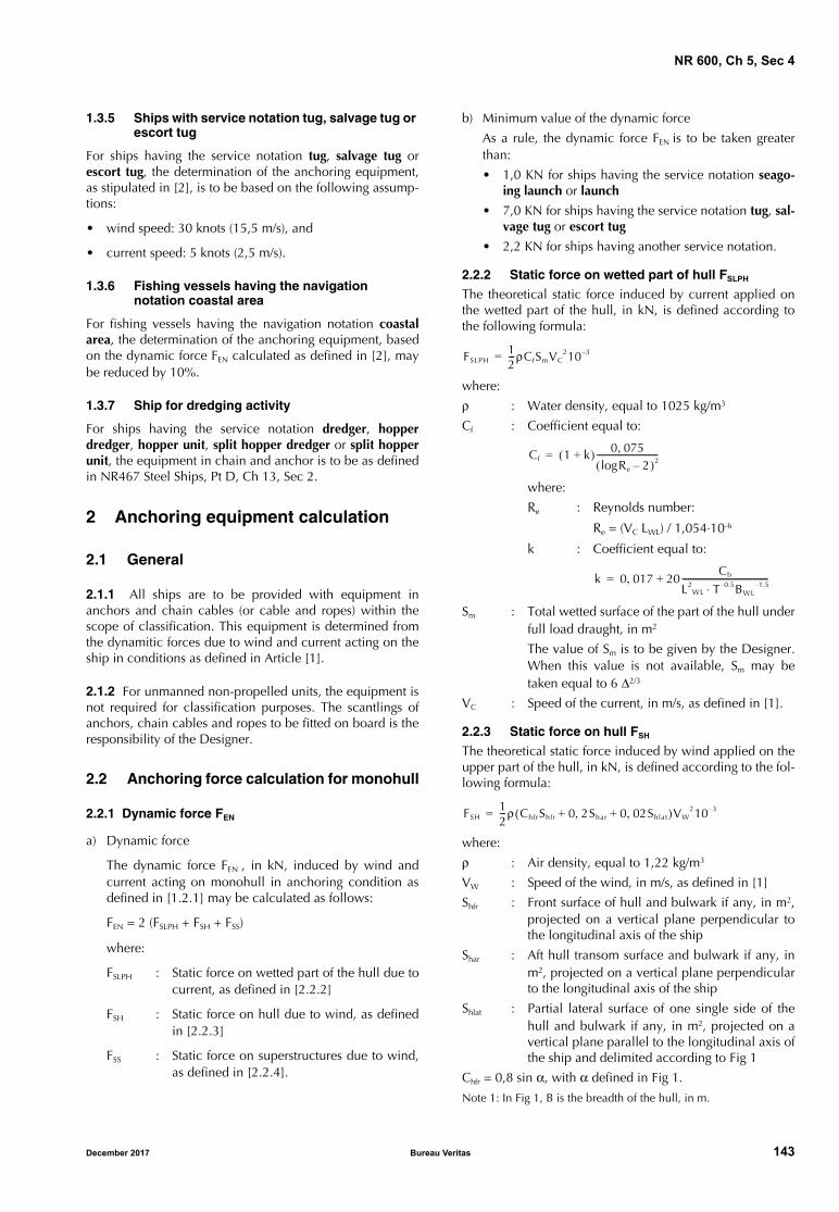
NR 600, Ch 5, Sec 4
1.3.5 Ships with service notation tug, salvage tug or escort tug
For ships having the service notation tug, salvage tug orescort tug, the determination of the anchoring equipment,as stipulated in [2], is to be based on the following assump-tions:
• wind speed: 30 knots (15,5 m/s), and
• current speed: 5 knots (2,5 m/s).
1.3.6 Fishing vessels having the navigation notation coastal area
For fishing vessels having the navigation notation coastalarea, the determination of the anchoring equipment, basedon the dynamic force FEN calculated as defined in [2], maybe reduced by 10%.
1.3.7 Ship for dredging activity
For ships having the service notation dredger, hopperdredger, hopper unit, split hopper dredger or split hopperunit, the equipment in chain and anchor is to be as definedin NR467 Steel Ships, Pt D, Ch 13, Sec 2.
2 Anchoring equipment calculation
2.1 General
2.1.1 All ships are to be provided with equipment inanchors and chain cables (or cable and ropes) within thescope of classification. This equipment is determined fromthe dynamitic forces due to wind and current acting on theship in conditions as defined in Article [1].
2.1.2 For unmanned non-propelled units, the equipment isnot required for classification purposes. The scantlings ofanchors, chain cables and ropes to be fitted on board is theresponsibility of the Designer.
2.2 Anchoring force calculation for monohull
2.2.1 Dynamic force FEN
a) Dynamic force
The dynamic force FEN , in kN, induced by wind andcurrent acting on monohull in anchoring condition asdefined in [1.2.1] may be calculated as follows:
FEN = 2 (FSLPH + FSH + FSS)
where:
FSLPH : Static force on wetted part of the hull due tocurrent, as defined in [2.2.2]
FSH : Static force on hull due to wind, as definedin [2.2.3]
FSS : Static force on superstructures due to wind,as defined in [2.2.4].
b) Minimum value of the dynamic force
As a rule, the dynamic force FEN is to be taken greaterthan:
• 1,0 KN for ships having the service notation seago-ing launch or launch
• 7,0 KN for ships having the service notation tug, sal-vage tug or escort tug
• 2,2 KN for ships having another service notation.
2.2.2 Static force on wetted part of hull FSLPH
The theoretical static force induced by current applied onthe wetted part of the hull, in kN, is defined according tothe following formula:
where:
ρ : Water density, equal to 1025 kg/m3
Cf : Coefficient equal to:
where:
Re : Reynolds number:
Re = (VC LWL) / 1,054⋅10-6
k : Coefficient equal to:
Sm : Total wetted surface of the part of the hull underfull load draught, in m2
The value of Sm is to be given by the Designer.When this value is not available, Sm may betaken equal to 6 Δ2/3
VC : Speed of the current, in m/s, as defined in [1].
2.2.3 Static force on hull FSH
The theoretical static force induced by wind applied on theupper part of the hull, in kN, is defined according to the fol-lowing formula:
where:
ρ : Air density, equal to 1,22 kg/m3
VW : Speed of the wind, in m/s, as defined in [1]
Shfr : Front surface of hull and bulwark if any, in m2,projected on a vertical plane perpendicular tothe longitudinal axis of the ship
Shar : Aft hull transom surface and bulwark if any, inm2, projected on a vertical plane perpendicularto the longitudinal axis of the ship
Shlat : Partial lateral surface of one single side of thehull and bulwark if any, in m2, projected on avertical plane parallel to the longitudinal axis ofthe ship and delimited according to Fig 1
Chfr = 0,8 sin α, with α defined in Fig 1.Note 1: In Fig 1, B is the breadth of the hull, in m.
FSLPH12---ρCfSmVC
210 3–=
Cf 1 k+( ) 0 075,Rlog e 2–( )2
------------------------------=
k 0 017, 20Cb
L2WL T 0.5– BWL
1.5–⋅------------------------------------------+=
FSH12---ρ ChfrShfr 0 2Shar, 0 02Shlat,+ +( )VW
210 3–=
December 2017 Bureau Veritas 143
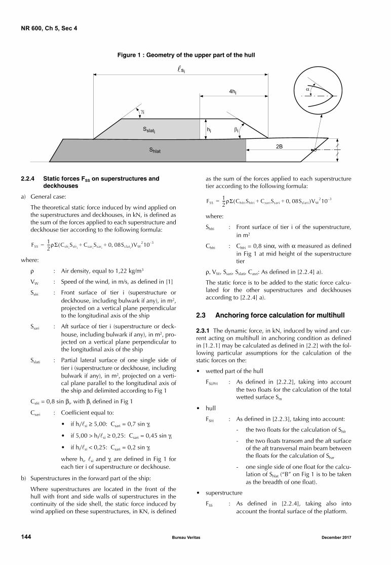
NR 600, Ch 5, Sec 4
Figure 1 : Geometry of the upper part of the hull
2.2.4 Static forces FSS on superstructures and deckhouses
a) General case:
The theoretical static force induced by wind applied onthe superstructures and deckhouses, in kN, is defined asthe sum of the forces applied to each superstructure anddeckhouse tier according to the following formula:
where:
ρ : Air density, equal to 1,22 kg/m3
VW : Speed of the wind, in m/s, as defined in [1]
Ssfri : Front surface of tier i (superstructure ordeckhouse, including bulwark if any), in m2,projected on a vertical plane perpendicularto the longitudinal axis of the ship
Ssari : Aft surface of tier i (superstructure or deck-house, including bulwark if any), in m2, pro-jected on a vertical plane perpendicular tothe longitudinal axis of the ship
Sslati : Partial lateral surface of one single side oftier i (superstructure or deckhouse, includingbulwark if any), in m2, projected on a verti-cal plane parallel to the longitudinal axis ofthe ship and delimited according to Fig 1
Csfri = 0,8 sin βi, with βi defined in Fig 1
Csari : Coefficient equal to:
• if hi/si ≥ 5,00: Csari = 0,7 sin γi
• if 5,00 > hi/si ≥ 0,25: Csari = 0,45 sin γi
• if hi/si < 0,25: Csari = 0,2 sin γi
where hi, si and γi are defined in Fig 1 foreach tier i of superstructure or deckhouse.
b) Superstructures in the forward part of the ship:
Where superstructures are located in the front of thehull with front and side walls of superstructures in thecontinuity of the side shell, the static force induced bywind applied on these superstructures, in KN, is defined
as the sum of the forces applied to each superstructuretier according to the following formula:
where:
Shfri : Front surface of tier i of the superstructure,in m2
Chfri : Chfri = 0,8 sinα, with α measured as definedin Fig 1 at mid height of the superstructuretier
ρ, VW, Ssari, Sslati, Casri: As defined in [2.2.4] a).
The static force is to be added to the static force calcu-lated for the other superstructures and deckhousesaccording to [2.2.4] a).
2.3 Anchoring force calculation for multihull
2.3.1 The dynamic force, in kN, induced by wind and cur-rent acting on multihull in anchoring condition as definedin [1.2.1] may be calculated as defined in [2.2] with the fol-lowing particular assumptions for the calculation of thestatic forces on the:
• wetted part of the hull
FSLPH : As defined in [2.2.2], taking into accountthe two floats for the calculation of the totalwetted surface Sm
• hull
FSH : As defined in [2.2.3], taking into account:
- the two floats for the calculation of Shfr
- the two floats transom and the aft surfaceof the aft transversal main beam betweenthe floats for the calculation of Shar
- one single side of one float for the calcu-lation of Shlat (“B” on Fig 1 is to be takenas the breadth of one float).
• superstructure
FSS : As defined in [2.2.4], taking also intoaccount the frontal surface of the platform.
���
���
������
�����
��
��
��
�
FSS12---ρΣ Csfri
SsfriCsari
Ssari0 08Sslati
,+ +( )VW210 3–=
FSS12---ρΣ ChfriShfri CsariSsari 0 08Sslati,+ +( )VW
210 3–=
144 Bureau Veritas December 2017
NR 600, Ch 5, Sec 4
3 Equipment in chain and anchor
3.1 Anchors
3.1.1 Mass of individual anchorThe individual mass of anchor, in kg, is to be at least equalto:
• for ordinary anchor: P = (FEN / 7) ⋅ 102
• for high holding power anchor: P = (FEN / 10) ⋅ 102
• for very high holding power: P = (FEN / 15) ⋅ 102
3.1.2 Number of anchorsAs a rule, the number of anchors to be provided on board isto be at least:
a) General case
• one anchor, when the dynamic force FEN calculatedaccording to [2.2] is less than 4,5 kN
• two anchors, when the dynamic force FEN calculatedaccording to [2.2] is between 4,5 kN and 45 kN
Note 1: For ships with FEN between 4,5 and 9,0 kN, the secondanchor may also be dispensed (except for passenger shipor ro-ro passenger ship having a navigation notation unre-stricted navigation). In this case, the weight of the anchorand the length and size of the chain cable are to be calcu-lated according to [3.1.1], [3.2.1] and [3.2.2], consideringFEN increased by one third.
• three anchors, when the dynamic force FEN calcu-lated according to [2.2] is greater than 45 kN.
Note 2: In this case, two anchors are to be connected to their ownchain cables and positioned on board always ready to use.The third anchor is intended as a spare one and is notrequired for the purpose of classification.
b) Ships having L ≤ 30 m, the service notation ro-ro pas-senger ship or passenger ship and a navigation notationother than unrestricted navigation
• one anchor
c) Ships with service notation seagoing launch or launch
Ships with FEN less than 4,7 kN are not required to carrya second anchor, except in the case of passenger launch.
For ships with FEN between 4,7 kN and 9,0 kN, the sec-ond anchor may also be dispensed with, except for pas-senger launch. In this case, the weight of the anchor isto be increased by one third and the length and size ofthe chain cable are to correspond to the increasedweight of the anchor according to [3.2.2].
d) Ships with service notation tug, salvage tug or escorttug:
A reduction of number of anchors may be acceptedaccording to Ch 6, Sec 1, [18.4].
3.1.3 Anchor design and performance testsAnchors are to be from an Approved Type. Therefore, Hold-ing power - performance - assessment, Design review andTests and examination on manufactured product are to becarried out.
Anchors are to have appropriate shape and scantlings incompliance with Society requirements. Moreover, they are
to be constructed in compliance with the Society require-ments.
A high or very high holding power anchor is suitable for useon board without any prior adjustment or special placementon the sea bottom.
For approval and/or acceptance as a high or very high hold-ing power anchor, the anchor is to have a holding powerequal, respectively, to at least twice or four times that of aType Approved ordinary stockless anchor of the same mass.
Holding power is to be assessed by full-scale comparativetests.
For very high holding power anchors, the holding powertest load is to be less than or equal to the proof load of theanchor, specified in NR216 Materials and Welding, Ch 4,Sec 1, [1.5.2].
Comparative tests on Type Approved Ordinary stocklessanchors are to be carried out at sea and are to provide satis-factory results on various types of seabeds.
Alternatively sea trials by comparison with a previouslyapproved HHP anchor may be accepted as a basis forapproval.
Such tests are to be carried out on anchors whose massesare, as far as possible, representative of the full range ofsizes proposed for the approval.
At least two anchors of different sizes are to be tested. Themass of the greatest anchor to be approved is not to be inexcess of 10 times that of the maximum size tested and themass of the smallest is to be not less than 0,1 times that ofthe minimum size tested.
Tests are normally to be carried out by means of a tug, but,alternatively, shore-based tests may be accepted.
The length of the chain cable connected to the testedanchor, having a diameter appropriate to its mass, is to besuch that the pull acting on the shank remains practicallyhorizontal. For this purpose a scope of chain cable equal to10 is deemed normal; however lower values may beaccepted.
Three tests are to be carried out for each anchor and type ofsea bottom. Three are the types of sea bottoms in whichtests are to be performed, e.g. soft mud or silt, sand or graveland hard clay or similar compounded.
The pull is to be measured by means of a dynamometer;measurements based on the bollard pull against propeller'srevolutions per minute curve may be accepted instead ofdynamometer readings.
Anchor stability and its ease of dragging are to be noteddown, whenever possible.
Upon satisfactory outcome of the above tests, the Societywill issue a certificate declaring the compliance of high orvery high holding power anchors with its relevant Rules.
3.1.4 Manufacturing, materials, test and examination
Manufacturing and materials are to comply with the rele-vant requirements of NR216 Materials and Welding.
Tests and examination requirements are to comply withNR216 Materials and Welding, Ch 4, Sec 1, [1.5].
December 2017 Bureau Veritas 145
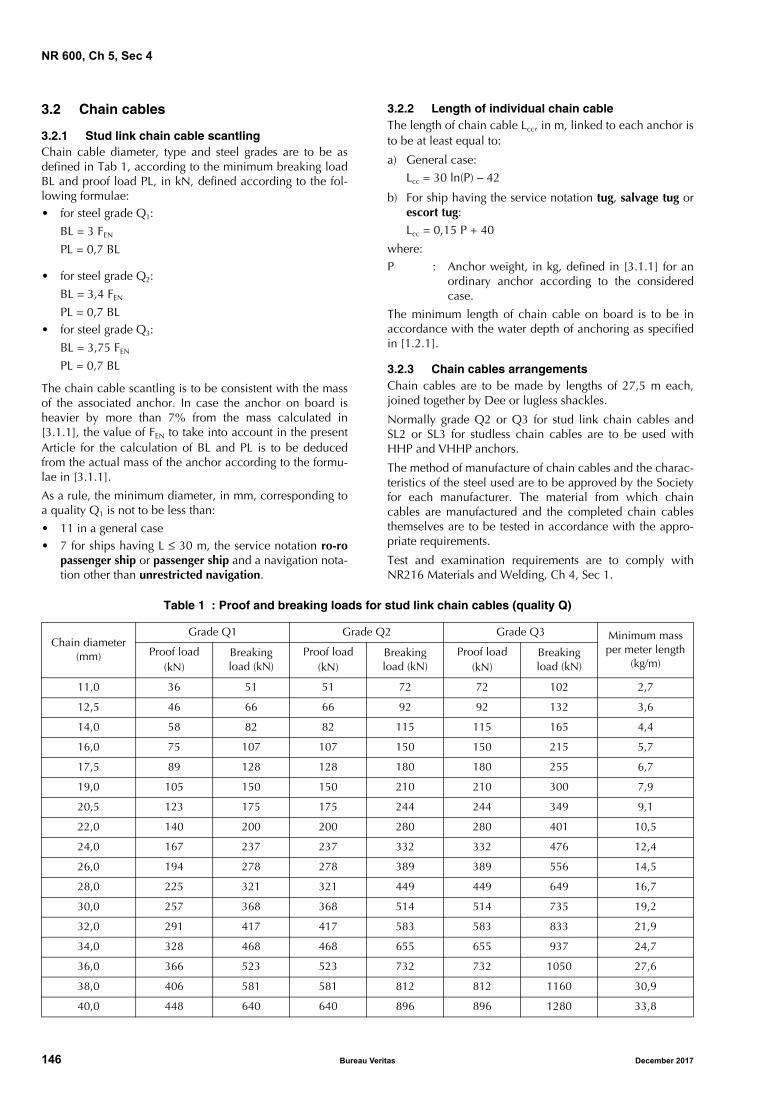
NR 600, Ch 5, Sec 4
3.2 Chain cables
3.2.1 Stud link chain cable scantlingChain cable diameter, type and steel grades are to be asdefined in Tab 1, according to the minimum breaking loadBL and proof load PL, in kN, defined according to the fol-lowing formulae: • for steel grade Q1:
BL = 3 FEN
PL = 0,7 BL
• for steel grade Q2:
BL = 3,4 FEN
PL = 0,7 BL• for steel grade Q3:
BL = 3,75 FEN
PL = 0,7 BL
The chain cable scantling is to be consistent with the massof the associated anchor. In case the anchor on board isheavier by more than 7% from the mass calculated in[3.1.1], the value of FEN to take into account in the presentArticle for the calculation of BL and PL is to be deducedfrom the actual mass of the anchor according to the formu-lae in [3.1.1].
As a rule, the minimum diameter, in mm, corresponding toa quality Q1 is not to be less than:
• 11 in a general case• 7 for ships having L ≤ 30 m, the service notation ro-ro
passenger ship or passenger ship and a navigation nota-tion other than unrestricted navigation.
3.2.2 Length of individual chain cable The length of chain cable Lcc, in m, linked to each anchor isto be at least equal to:
a) General case:Lcc = 30 ln(P) − 42
b) For ship having the service notation tug, salvage tug orescort tug:Lcc = 0,15 P + 40
where:P : Anchor weight, in kg, defined in [3.1.1] for an
ordinary anchor according to the consideredcase.
The minimum length of chain cable on board is to be inaccordance with the water depth of anchoring as specifiedin [1.2.1].
3.2.3 Chain cables arrangementsChain cables are to be made by lengths of 27,5 m each,joined together by Dee or lugless shackles.
Normally grade Q2 or Q3 for stud link chain cables andSL2 or SL3 for studless chain cables are to be used withHHP and VHHP anchors.
The method of manufacture of chain cables and the charac-teristics of the steel used are to be approved by the Societyfor each manufacturer. The material from which chaincables are manufactured and the completed chain cablesthemselves are to be tested in accordance with the appro-priate requirements.
Test and examination requirements are to comply withNR216 Materials and Welding, Ch 4, Sec 1.
Table 1 : Proof and breaking loads for stud link chain cables (quality Q)
Chain diameter(mm)
Grade Q1 Grade Q2 Grade Q3 Minimum mass per meter length
(kg/m)Proof load
(kN)Breaking load (kN)
Proof load(kN)
Breaking load (kN)
Proof load(kN)
Breaking load (kN)
11,0 36 51 51 72 72 102 2,7
12,5 46 66 66 92 92 132 3,6
14,0 58 82 82 115 115 165 4,4
16,0 75 107 107 150 150 215 5,7
17,5 89 128 128 180 180 255 6,7
19,0 105 150 150 210 210 300 7,9
20,5 123 175 175 244 244 349 9,1
22,0 140 200 200 280 280 401 10,5
24,0 167 237 237 332 332 476 12,4
26,0 194 278 278 389 389 556 14,5
28,0 225 321 321 449 449 649 16,7
30,0 257 368 368 514 514 735 19,2
32,0 291 417 417 583 583 833 21,9
34,0 328 468 468 655 655 937 24,7
36,0 366 523 523 732 732 1050 27,6
38,0 406 581 581 812 812 1160 30,9
40,0 448 640 640 896 896 1280 33,8
146 Bureau Veritas December 2017
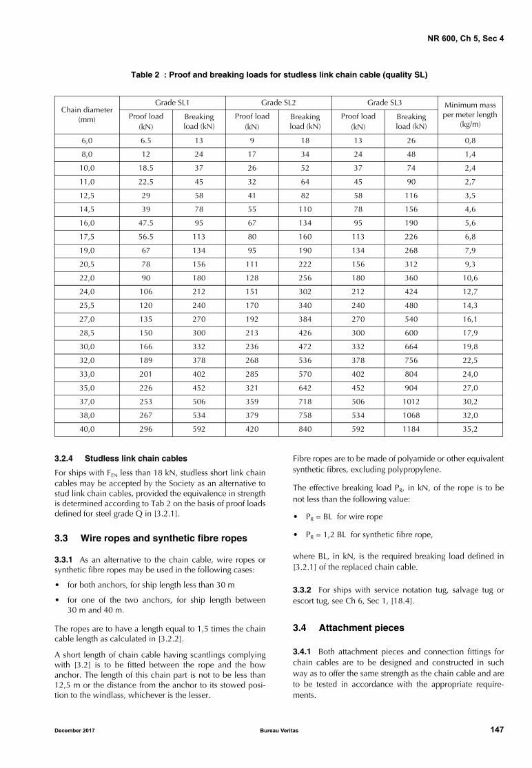
NR 600, Ch 5, Sec 4
Table 2 : Proof and breaking loads for studless link chain cable (quality SL)
3.2.4 Studless link chain cables
For ships with FEN less than 18 kN, studless short link chaincables may be accepted by the Society as an alternative tostud link chain cables, provided the equivalence in strengthis determined according to Tab 2 on the basis of proof loadsdefined for steel grade Q in [3.2.1].
3.3 Wire ropes and synthetic fibre ropes
3.3.1 As an alternative to the chain cable, wire ropes orsynthetic fibre ropes may be used in the following cases:
• for both anchors, for ship length less than 30 m
• for one of the two anchors, for ship length between30 m and 40 m.
The ropes are to have a length equal to 1,5 times the chaincable length as calculated in [3.2.2].
A short length of chain cable having scantlings complyingwith [3.2] is to be fitted between the rope and the bowanchor. The length of this chain part is not to be less than12,5 m or the distance from the anchor to its stowed posi-tion to the windlass, whichever is the lesser.
Fibre ropes are to be made of polyamide or other equivalentsynthetic fibres, excluding polypropylene.
The effective breaking load PR, in kN, of the rope is to benot less than the following value:
• PR = BL for wire rope
• PR = 1,2 BL for synthetic fibre rope,
where BL, in kN, is the required breaking load defined in[3.2.1] of the replaced chain cable.
3.3.2 For ships with service notation tug, salvage tug orescort tug, see Ch 6, Sec 1, [18.4].
3.4 Attachment pieces
3.4.1 Both attachment pieces and connection fittings forchain cables are to be designed and constructed in suchway as to offer the same strength as the chain cable and areto be tested in accordance with the appropriate require-ments.
Chain diameter (mm)
Grade SL1 Grade SL2 Grade SL3 Minimum mass per meter length
(kg/m)Proof load
(kN)Breaking load (kN)
Proof load(kN)
Breaking load (kN)
Proof load(kN)
Breaking load (kN)
6,0 6.5 13 9 18 13 26 0,8
8,0 12 24 17 34 24 48 1,4
10,0 18.5 37 26 52 37 74 2,4
11,0 22.5 45 32 64 45 90 2,7
12,5 29 58 41 82 58 116 3,5
14,5 39 78 55 110 78 156 4,6
16,0 47.5 95 67 134 95 190 5,6
17,5 56.5 113 80 160 113 226 6,8
19,0 67 134 95 190 134 268 7,9
20,5 78 156 111 222 156 312 9,3
22,0 90 180 128 256 180 360 10,6
24,0 106 212 151 302 212 424 12,7
25,5 120 240 170 340 240 480 14,3
27,0 135 270 192 384 270 540 16,1
28,5 150 300 213 426 300 600 17,9
30,0 166 332 236 472 332 664 19,8
32,0 189 378 268 536 378 756 22,5
33,0 201 402 285 570 402 804 24,0
35,0 226 452 321 642 452 904 27,0
37,0 253 506 359 718 506 1012 30,2
38,0 267 534 379 758 534 1068 32,0
40,0 296 592 420 840 592 1184 35,2
December 2017 Bureau Veritas 147

NR 600, Ch 5, Sec 4
4 Shipboard fittings for anchoring equipment
4.1 General
4.1.1 The anchor windlasses are to comply with NR626Anchor Windlass.
4.1.2 Brake capacity
The windlass brake is to be sufficient to withstand the fol-lowing loads:
• 0,8 time the breaking load BL of the chain defined in[3.2.1], if not combined with a chain stopper,
• 1,2 time the value of FEN defined in [2.2.1] if combinedwith a chain stopper.
4.1.3 Chain stopper
When a chain stopper is fitted, it is to be able to withstand apull of 80% of the breaking load of the chain, without anypermanent deformation of the stresses parts.
4.1.4 Deck reinforcement under windlass and chain stopper
Local reinforcement of deck structure are to be provided inway of windlass and chain stopper, and designed in accord-ance with NR626 Anchor Windlass for steel and aluminiumstructure.
For composite materials structure, local reinforcementstructure are to designed in accordance with:
a) Windlass without chain stopper: Brake capacity asdefined in [4.1.2] taking into account safety factorsequal to SF and SFCS
b) Windlass combined with chain stopper:
1) Windlass: Brake capacity as defined in [4.1.2] takinginto account safety factors equal to 0,7 SF and 0,7SFCS
2) Chain stopper: Design load defined in [4.1.3] takinginto account safety factors equal to SF and SFCS
where:
SF : Safety factor for structure checked with mini-mum stress criteria in layers as defined in Ch 2,Sec 3, [3.2.3]
SFCS : Safety factor for structure checked with com-bined stress criteria in layers as defined in Ch 2,Sec 3, [3.2.3].
4.2 Chain locker
4.2.1 The chain locker is to be of a capacity adequate tostow all chain cable equipment and provide an easy directlead to the windlass.
Where two anchor lines are fitted, the port and starboardchain cables are to be separated by a bulkhead in the locker.
The inboard ends of chain cables are to be secured to thestructure by a fastening able to withstand a force not lessthan 15% of the breaking load of the chain cable.
In an emergency, the attachments are to be easily releasedfrom outside the chain locker.
Where the chain locker is arranged aft of the collision bulk-head, its boundary bulkheads are to be watertight and adrainage system provided.
5 Shipboard fittings for towing and mooring
5.1 General
5.1.1 The equipment for mooring and or towing are notcovered within the scope of classification.
However, deck reinforcements under mooring and towingequipment such as, bitts, bollard, fairleads, chocks... are tobe examined within the scope of hull drawing examination.
For ships of 500 GT and above, the requirements of NR467Steel Ships, Pt B, Ch 9, Sec 4, [5] are to be applied, consid-ering an equivalent equipment number EN equal to fivetimes the value of FEN as calculated in [2.2.1].
5.1.2 Documents to be submitted
Maximum safe working loads of equipment used for themooring and the towing are to be specified.
A mooring and towing arrangement plan is to be submittedto the Society for information. This plan is to define themethod of use the mooring and towing lines and to includethe equipment location on the deck, the fitting type, the safeworking loads and the manner of applying mooring andtowing lines (including line angles).
5.1.3 Hull structure reinforcement
As a general rule, hull structure reinforcements in way ofmooring and towing equipment are to be examined bydirect calculation, taking into account:
• a tension in the mooring or towing line equal to the safeworking load of the equipment, and
• the permissible stresses and safety factors as defined inCh 2, Sec 3.
Note 1: When the mooring plan is not available, the equipmentsuch as bitts and bollards (when the line may come and go from thesame direction) are to be loaded up to twice their safe workingloads.
148 Bureau Veritas December 2017
NR 600
Chapter 6
ADDITIONAL REQUIREMENTS IN RELATION TOTHE SERVICE NOTATION OR SERVICE FEATURE
ASSIGNED TO THE SHIP
SECTION 1 ADDITIONAL REQUIREMENTS IN RELATION TO THE SERVICE NOTATION OR SERVICE FEATURE ASSIGNED TO THE SHIP
December 2017 Bureau Veritas 149

150 Bureau Veritas December 2017
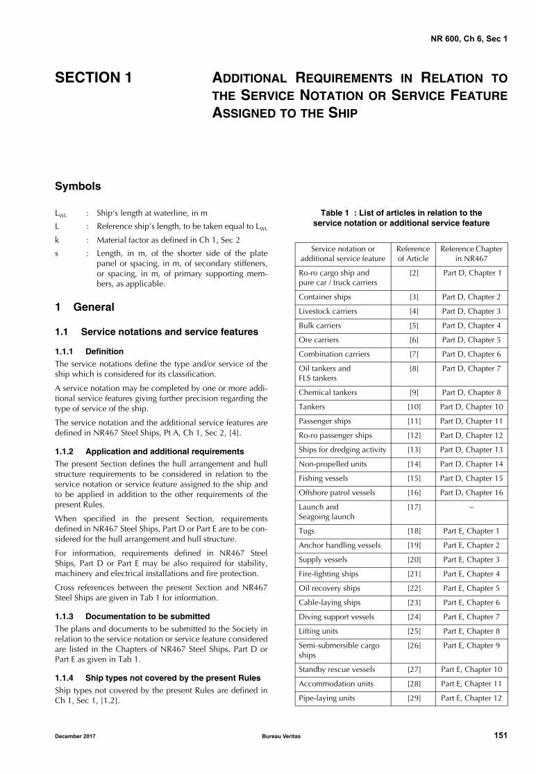
NR 600, Ch 6, Sec 1
SECTION 1 ADDITIONAL REQUIREMENTS IN RELATION TO
THE SERVICE NOTATION OR SERVICE FEATURE
ASSIGNED TO THE SHIP
Symbols
LWL : Ship‘s length at waterline, in m
L : Reference ship’s length, to be taken equal to LWL
k : Material factor as defined in Ch 1, Sec 2
s : Length, in m, of the shorter side of the platepanel or spacing, in m, of secondary stiffeners,or spacing, in m, of primary supporting mem-bers, as applicable.
1 General
1.1 Service notations and service features
1.1.1 DefinitionThe service notations define the type and/or service of theship which is considered for its classification.
A service notation may be completed by one or more addi-tional service features giving further precision regarding thetype of service of the ship.
The service notation and the additional service features aredefined in NR467 Steel Ships, Pt A, Ch 1, Sec 2, [4].
1.1.2 Application and additional requirementsThe present Section defines the hull arrangement and hullstructure requirements to be considered in relation to theservice notation or service feature assigned to the ship andto be applied in addition to the other requirements of thepresent Rules.
When specified in the present Section, requirementsdefined in NR467 Steel Ships, Part D or Part E are to be con-sidered for the hull arrangement and hull structure.
For information, requirements defined in NR467 SteelShips, Part D or Part E may be also required for stability,machinery and electrical installations and fire protection.
Cross references between the present Section and NR467Steel Ships are given in Tab 1 for information.
1.1.3 Documentation to be submittedThe plans and documents to be submitted to the Society inrelation to the service notation or service feature consideredare listed in the Chapters of NR467 Steel Ships, Part D orPart E as given in Tab 1.
1.1.4 Ship types not covered by the present RulesShip types not covered by the present Rules are defined inCh 1, Sec 1, [1.2].
Table 1 : List of articles in relation to theservice notation or additional service feature
Service notation or additional service feature
Reference of Article
Reference Chapter in NR467
Ro-ro cargo ship and pure car / truck carriers
[2] Part D, Chapter 1
Container ships [3] Part D, Chapter 2
Livestock carriers [4] Part D, Chapter 3
Bulk carriers [5] Part D, Chapter 4
Ore carriers [6] Part D, Chapter 5
Combination carriers [7] Part D, Chapter 6
Oil tankers and FLS tankers
[8] Part D, Chapter 7
Chemical tankers [9] Part D, Chapter 8
Tankers [10] Part D, Chapter 10
Passenger ships [11] Part D, Chapter 11
Ro-ro passenger ships [12] Part D, Chapter 12
Ships for dredging activity [13] Part D, Chapter 13
Non-propelled units [14] Part D, Chapter 14
Fishing vessels [15] Part D, Chapter 15
Offshore patrol vessels [16] Part D, Chapter 16
Launch and Seagoing launch
[17] −
Tugs [18] Part E, Chapter 1
Anchor handling vessels [19] Part E, Chapter 2
Supply vessels [20] Part E, Chapter 3
Fire-fighting ships [21] Part E, Chapter 4
Oil recovery ships [22] Part E, Chapter 5
Cable-laying ships [23] Part E, Chapter 6
Diving support vessels [24] Part E, Chapter 7
Lifting units [25] Part E, Chapter 8
Semi-submersible cargo ships
[26] Part E, Chapter 9
Standby rescue vessels [27] Part E, Chapter 10
Accommodation units [28] Part E, Chapter 11
Pipe-laying units [29] Part E, Chapter 12
December 2017 Bureau Veritas 151

NR 600, Ch 6, Sec 1
2 Ro-ro cargo ships and pure car/truck carriers
2.1 Application
2.1.1 Ships having the service notation ro-ro cargo ship orPCT carrier are to comply with the requirements of the pres-ent Article.
2.2 General
2.2.1 Wood sheathing
Wood sheathing is recommended for caterpillar trucks andunusual vehicles.
2.2.2 Global transverse strength
When deemed necessary by the Society, the behaviour ofthe ship primary structural members under racking effectdue to transverse forces induced by transverse accelerationsis to be investigated by direct calculation on a case by casebasis.
2.3 Hull scantlings for steel structure
2.3.1 Plating
The thickness of the weather strength deck and trunk deckplating is to be not less than the values obtained, in mm,from the following formula:
t = 3,6 + 0,013 L + 4,5 s
where:
s : Length, in m, of the shorter side of the platepanel.
2.3.2 Inner bottom of cargo holds intended to carry dry cargo
The inner bottom thickness calculated as defined in Ch 4,Sec 3, [2] is to be increased by 2 mm unless it is protectedby a continuous wooden ceiling.
3 Container ships
3.1 Application
3.1.1 Ships having the service notation container ship andships assigned with the additional service feature equippedfor carriage of containers are to comply with the require-ments of the present Article.
3.1.2 The additional requirements of this Article apply tocontainer ships intended to carry containers in holds and/oron deck.
3.2 Structure design principles
3.2.1 General strength principles
Local reinforcements of the hull structure are to be providedunder container corners and in way of fixed cargo securingdevices and cell guides, if fitted.
The forces applying on the fixed cargo securing devices areto be indicated by the Designer. When one of the additionalclass notations LASHING, LASHING-WW or LASHING(restricted area) is granted, these forces may be determinedby the Society.
3.2.2 Structural continuityOn double hull ships, where the machinery space is locatedbetween two holds, the inner side is, in general, to be con-tinuous within the machinery space. Where the machineryspace is situated aft, the inner hull is to extend as far abaftas possible and be tapered at the ends.
3.2.3 Bottom structure
a) Floor and girder spacing:
The floor spacing is to be such that floors are located inway of the container corners. Floors are also to be fittedin way of watertight bulkheads.
Girders are generally to be fitted in way of containercorners.
b) Reinforcement in way of cell guides:
The structure of the bottom and inner bottom on whichcell guides rest is to be adequately stiffened with dou-blers, brackets or other equivalent reinforcements.
3.2.4 Side structureThe topside torsion box girders are to be longitudinallyframed.
Where the side is longitudinally framed, side transversestructure is to be fitted in line with the double bottom floors.
3.2.5 Deck structure
a) Longitudinal girders between hatchways:
The width of the longitudinal deck girders and hatchcoaming flanges is to be such as to accommodate thehatch covers and their securing arrangements.
The connections of the longitudinal deck girders andhatch coamings with the machinery space structure,and aft and fore part structures are to ensure propertransmission of stresses from the girders to the adjacentstructures.
b) Cross decks:
Cross decks between hatches are subject to a shearforce in the longitudinal direction induced by the over-all torsion of the ship. The adequate strength of thesedeck strips is to be checked in that respect.
Cross decks between hatches are to be suitably over-lapped at ends.
c) Deck and hatch cover reinforcements:
Deck or hatch cover structures are to be reinforced tak-ing into account the loads transmitted by the corners ofcontainers and cell guides.
3.2.6 Bulkhead structure
a) Transverse box structures in way of transverse watertightbulkheads:
Bottom and top transverse box structures are generallyto be provided in way of transverse watertight bulkheadsat the inner bottom and deck level, respectively.
152 Bureau Veritas December 2017
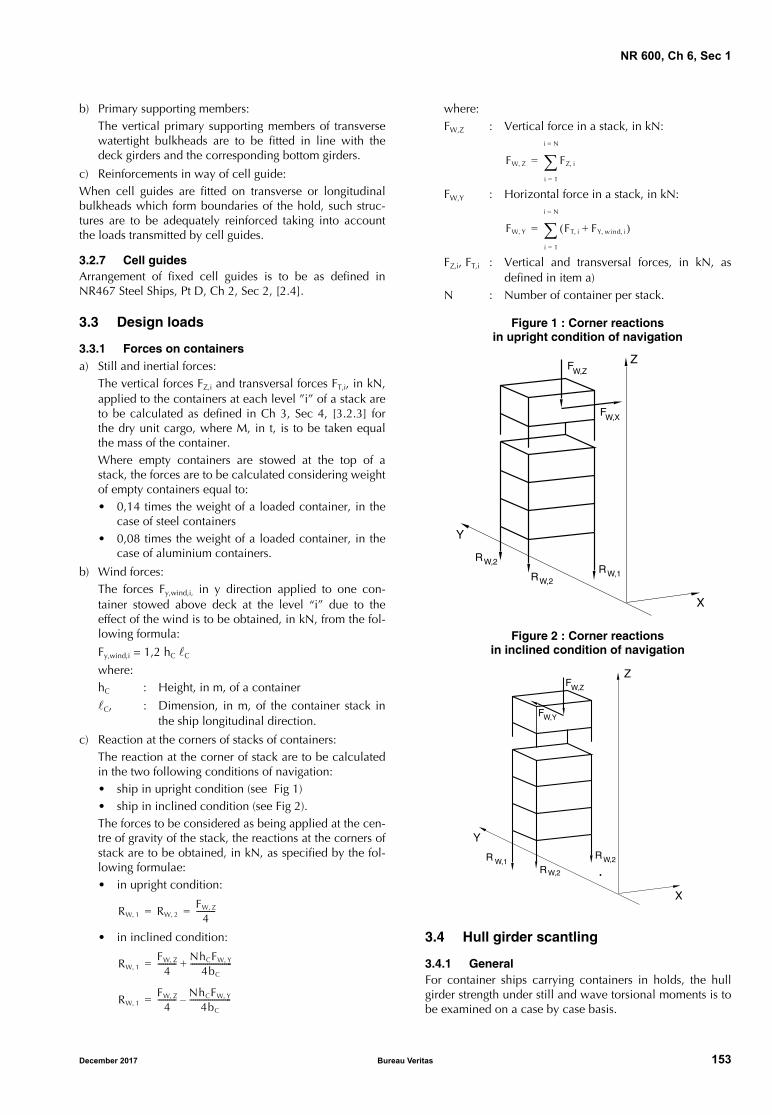
NR 600, Ch 6, Sec 1
b) Primary supporting members:The vertical primary supporting members of transversewatertight bulkheads are to be fitted in line with thedeck girders and the corresponding bottom girders.
c) Reinforcements in way of cell guide:When cell guides are fitted on transverse or longitudinalbulkheads which form boundaries of the hold, such struc-tures are to be adequately reinforced taking into accountthe loads transmitted by cell guides.
3.2.7 Cell guidesArrangement of fixed cell guides is to be as defined inNR467 Steel Ships, Pt D, Ch 2, Sec 2, [2.4].
3.3 Design loads
3.3.1 Forces on containersa) Still and inertial forces:
The vertical forces FZ,i and transversal forces FT,i, in kN,applied to the containers at each level ”i” of a stack areto be calculated as defined in Ch 3, Sec 4, [3.2.3] forthe dry unit cargo, where M, in t, is to be taken equalthe mass of the container.Where empty containers are stowed at the top of astack, the forces are to be calculated considering weightof empty containers equal to:• 0,14 times the weight of a loaded container, in the
case of steel containers• 0,08 times the weight of a loaded container, in the
case of aluminium containers.
b) Wind forces:The forces Fy,wind,i, in y direction applied to one con-tainer stowed above deck at the level “i” due to theeffect of the wind is to be obtained, in kN, from the fol-lowing formula:
Fy,wind,i = 1,2 hC C
where:hC : Height, in m, of a container
C, : Dimension, in m, of the container stack inthe ship longitudinal direction.
c) Reaction at the corners of stacks of containers:The reaction at the corner of stack are to be calculatedin the two following conditions of navigation: • ship in upright condition (see Fig 1)• ship in inclined condition (see Fig 2).The forces to be considered as being applied at the cen-tre of gravity of the stack, the reactions at the corners ofstack are to be obtained, in kN, as specified by the fol-lowing formulae: • in upright condition:
• in inclined condition:
where:FW,Z : Vertical force in a stack, in kN:
FW,Y : Horizontal force in a stack, in kN:
FZ,i, FT,i : Vertical and transversal forces, in kN, asdefined in item a)
N : Number of container per stack.
Figure 1 : Corner reactionsin upright condition of navigation
Figure 2 : Corner reactionsin inclined condition of navigation
3.4 Hull girder scantling
3.4.1 GeneralFor container ships carrying containers in holds, the hullgirder strength under still and wave torsional moments is tobe examined on a case by case basis.
RW 1, RW 2,FW Z,
4----------= =
RW 1,FW Z,
4---------- NhCFW Y,
4bC
----------------------+=
RW 1,FW Z,
4---------- NhCFW Y,
4bC
----------------------–=
FW Z, FZ i,
i 1=
i N=
=
FW Y, FT i, FY wind i,,+( )i 1=
i N=
=
FW,ZZ
X
Y
FW,X
RW,1RW,2
RW,2
Z
X
Y
R W,1RW,2
RW,2
FW,Y
FW,Z
December 2017 Bureau Veritas 153
NR 600, Ch 6, Sec 1
4 Livestock carriers
4.1 Application
4.1.1 Ships having the service notation livestock carrier areto comply with the requirements of the present Article.
4.2 General arrangement design
4.2.1 General arrangement design is to be as defined inNR467 Steel Ships, Pt D, Ch 3, Sec 2, [2].
4.3 Hull girder strength and hull scantlings
4.3.1 Hull girder strength
In general, the decks and platform decks above the strengthdeck used for the carriage of livestock may not be taken intoaccount for the calculation of the section modulus.
4.3.2 Movable or collapsible structural elements above the strength deck
In general, the movable or collapsible structural elementsabove the strength deck used for the stocking and the distri-bution of livestock on decks or platform decks are not a partof ship classification.
5 Bulk carriers
5.1 Application
5.1.1 Ships having one of the service notations bulk carrierESP or bulk carrier are to comply with the requirements ofthe present Article.
5.1.2 As a rule, the hull structure of ships whose servicenotation is completed by the additional service feature non-homload as defined in NR467 Steel Ships, Pt D, Ch 4, Sec3, [3.1.2], is to be checked according to NR467 Steel Ships,Part B instead of the present Rules.
5.2 Ship arrangement
5.2.1 Specific ship arrangement is to comply with require-ments defined in NR467 Steel Ships, Pt D, Ch 4, Sec 2.
5.3 Structure design principles
5.3.1 Structure design principles defined in NR467 SteelShips, Pt D, Ch 4, Sec 3, [2], are applicable.
5.4 Design loads
5.4.1 Application
In addition to the requirements of Chapter 3, the loadingconditions, subdivided into departure and arrival condi-tions, defined in NR467 Steel Ships, Pt D, Ch 4, Sec 3,[3.1.2] are to be taken into account for hull girder strengthand local strength analysis according to the present Rules.
5.4.2 Additional requirements on local loads for ships with the additional service feature heavycargo
For ships with a service notation completed by the addi-tional service feature heavycargo [AREA1, X1 kN/m2 -AREA2, X2 kN/m2 - ...] as defined in NR467 Steel Ships,Part A the values of pDB used to calculate the dry uniformcargo as defined in Ch 3, Sec 4, [3.2.2], in kN/m2, are to bespecified by the Designer for each AREAi, and introducedas Xi values in the above service feature.
5.4.3 Loading conditions for primary structure analysis
The following loading conditions are to be considered inthe analysis of the primary structure:
• homogeneous loading and corresponding draught T
• heavy ballast (the ballast hold being full) and corre-sponding draught T.
5.5 Hull scantlings for steel structure
5.5.1 Plating
As a rule, the thickness of the side plating located betweenhopper and topside tanks, in mm, is to be not less than:
tMIN = L0,5 + 2
5.5.2 Inner bottom of cargo holds intended to carry dry cargo
The inner bottom thickness calculated as defined in Ch 4,Sec 3, [2] is to be increased by 2 mm unless it is protectedby a continuous wooden ceiling.
5.5.3 Secondary stiffeners
The thicknesses of side frames and their brackets, in way ofcargo holds, are to be not less than the values given in Tab 2.
Table 2 : Minimum thickness ofside frames and brackets
Item Minimum thickness, in mm
Side frame webs
CL (7,0 + 0,03 LWL) + 1,75
Lower end bracket
The greater of the following:• CL (7,0 + 0,03 LWL) + 3,75• as fitted thickness of side frame web
Upper end bracket
The greater of the following:• CL (7,0 + 0,03 LWL) + 1,75• as fitted thickness of side frame web
Note 1:CL : Coefficient equal to:
• 1,15 for side frames in way of the foremost cargo hold
• 1 for side frames in way of the other cargo holds.
154 Bureau Veritas December 2017
NR 600, Ch 6, Sec 1
5.5.4 Scantlings of side frames adjacent to the collision bulkhead
The scantlings of side frames in way of the foremost cargohold and immediately adjacent to the collision bulkheadare to be increased by 25% with respect to those deter-mined according to Chapter 4, in order to prevent excessiveimposed deformation on the side shell plating.
As an alternative, supporting structures are to be fittedwhich maintain the continuity of fore peak girders withinthe foremost cargo hold.
5.6 Hatch covers
5.6.1 Steel large hatch covers are to be as defined inNR467 Steel Ships, Pt D, Ch 4, Sec 4.
5.7 Protection of hull metallic structure
5.7.1 Protection of cargo hold is to be as defined in NR467Steel Ships, Pt D, Ch 4, Sec 3, [7].
In these requirements, references to NR467, Part B are to bereplaced by the equivalent requirements defined in thepresent Rules.
5.8 Construction and testing
5.8.1 Construction and testing are to fulfil the requirementsof NR467 Steel Ships, Pt D, Ch 4, Sec 3, [8].
6 Ore carriers
6.1 Application
6.1.1 Ships having the service notation ore carrier are tocomply with the requirements of the present Article.
6.1.2 As a rule, for ships having alternate light and heavycargo loading conditions, the hull scantlings are to bechecked according to NR467 Steel Ships, Part B instead ofthe present Rules.
6.2 Ship arrangement
6.2.1 Specific ship arrangement is to comply with therequirements defined in NR467 Steel Ships, Pt D, Ch 5, Sec 2.
6.3 Structure design principles
6.3.1 Structure design principle defined in NR467 SteelShips, Pt D, Ch 5, Sec 3, [3] are applicable.
6.4 Design loads
6.4.1 Application
In addition to the requirements of Chapter 3, the loadingconditions, subdivided into departure and arrival condi-tions, defined in NR467 Steel Ships, Pt D, Ch 5, Sec 3,[4.1.1] are applicable for hull girder and primary structureanalysis according to the present Rules.
6.5 Hull scantlings for steel structure
6.5.1 Minimum thickness of the inner bottom plating in holds
The inner bottom thickness calculated as defined in Ch 4,Sec 3, [2] is to be increased by 2 mm unless it is protectedby a continuous wooden ceiling.
As a rule, the minimum thickness, in mm, of the inner bot-tom plating in holds is not to be less than:
tMIN = 2,15 (LWL1/3 k1/6) + 4,4 s + 2
where:
s : Length, in m, of the shorter side of the platepanel.
6.5.2 Strength checks of cross-ties analysed through a three dimensional beam analysis
Cross-tie analysis is to be carried out as defined in NR467Pt D, Ch 5, Sec 3, [5.3].
6.6 Hatch covers
6.6.1 Steel large hatch covers are to be as defined inNR467 Steel Ships, Pt D, Ch 4, Sec 4 for hatch covers ofships having the service notation bulk carrier.
6.7 Construction and testing
6.7.1 Construction and testing are to fulfil the requirementsof NR467 Steel Ships, Pt D, Ch 5, Sec 3, [7].
In these requirements, references to NR467, Part B are to bereplaced by the equivalent requirements defined in thepresent Rules.
7 Combination carriers
7.1 Application
7.1.1 Ships having the service notation combination carrierare to comply with the requirements of the present Article.
7.1.2 As a rule, for ships having alternate light and heavycargo loading conditions, the hull scantlings are to bechecked according to NR467 Steel Ships, Part B instead ofthe present Rules.
7.2 Ship arrangement
7.2.1 Specific ship arrangement is to comply with therequirements defined in NR467 Steel Ships, Pt D, Ch 6, Sec 2.
7.3 Structure design principles
7.3.1 As far as practicable, structure design principles areto be examined on the basis of the requirements defined inNR467 Steel Ships, Pt D, Ch 6, Sec 3, [3] and Pt D, Ch 6,Sec 3, [4] for ships having the service notation combinationcarrier/OBO ESP and combination carrier/OOC ESPrespectively.
December 2017 Bureau Veritas 155
NR 600, Ch 6, Sec 1
7.4 Design loads
7.4.1 ApplicationIn addition to the requirements of Chapter 3, the loadingconditions, subdivided into departure and arrival condi-tions, defined in NR467 Steel Ships, Pt D, Ch 6, Sec 3,[5.1.1] are applicable.
7.4.2 Oil cargo mass densityIn the absence of more precise values, an oil cargo mass den-sity of 0,9 t/m3 is to be considered for calculating the internalpressures and forces in cargo tanks according to Ch 3, Sec 4.
7.5 Hull scantlings for steel structure
7.5.1 PlatingAs a rule, the thickness of the plating of the inner bottom inholds intended to carry ore, of the strength deck and ofbulkheads is to be not less than the values given in Tab 3.
Table 3 : Minimum plating thickness
7.5.2 Secondary stiffenersThe thickness of the web of secondary stiffeners is to be notless than the value obtained, in mm, from the following for-mula:
tMIN = 0,75 L1/3 k1/6 + 4,5 s + 3
where s is the spacing, in m, of secondary stiffeners.
7.5.3 Primary stiffeners
a) Minimum thickness:
The thickness of plating which forms the webs of pri-mary supporting members is to be not less than thevalue obtained, in mm, from the following formula:
tMIN = 1,45 L1/3 k1/6 + 3
b) Strength check of primary structure through a three-dimensional beam model:
Where the primary structure is checked through a threedimensional beam model, the requirements of NR467Steel Ships, Pt D, Ch 6, Sec 3, [6.3] are to be applied.
7.5.4 Strength check with respect to stresses due to the temperature gradient
Direct calculations of stresses induced in the hull structuresby the temperature gradient are to be performed for shipsintended to carry cargoes at temperatures exceeding 90°C.In these calculations, the water temperature is to beassumed equal to 0°C.
The calculations are to be submitted to the Society forreview.
7.6 Other structures
7.6.1 Inner bottom of cargo holds intended to carry dry cargo
The inner bottom thickness for steel structure calculated asdefined in Ch 4, Sec 3, [2] is to be increased by 2 mmunless it is protected by a continuous wooden ceiling.
7.6.2 Machinery space and opening arrangement are to bein accordance with the requirements of NR467 Steel Ships,Pt D, Ch 6, Sec 3, [7].
7.6.3 Steel large hatch covers are to be as defined inNR467 Steel Ships, Pt D, Ch 4, Sec 4 for hatch covers ofships having the service notation bulk carrier.
7.7 Protection of hull metallic structures
7.7.1 Requirements of NR467 Steel Ships, Pt D, Ch 6, Sec 3,[9] are applicable.
7.8 Cathodic protection of tanks
7.8.1 Requirements of NR467 Steel Ships, Pt D, Ch 6, Sec 3,[10] are applicable.
7.9 Construction and testing
7.9.1 Requirements of NR467 Steel Ships, Pt D, Ch 6, Sec 3,[11] are applicable.
In these requirements, references to NR467, Part B are to bereplaced by the equivalent requirements defined in thepresent Rules.
8 Oil tankers and FLS tankers
8.1 Application
8.1.1 Ships having the service notation oil tanker are tocomply with the requirements of the present Article, takinginto account the general requirements defined in NR467Steel Ships, Pt D, Ch 7, SeC 1.
8.1.2 As a rule, for ships having non homogeneous loadingconditions, the hull scantlings are to be checked accordingto NR467 Steel Ships, Part B instead of the present Rules.
8.2 Ship arrangement
8.2.1 Specific ship arrangement is to comply with therequirements defined in NR467 Steel Ships, Pt D, Ch 7, Sec 2.
8.3 Design loads
8.3.1 Application
In addition to the requirements of Chapter 3, the hull girderload conditions, subdivided into departure and arrival con-ditions, defined in NR467 Steel Ships, Pt D, Ch 7, Sec 3,[4.1.1] are applicable.
Plating Minimum thickness, in mm
Strength deck (5,5 + 0,02 L) k1/2 + 1,5
Inner bottom in holds intended to carry ore
2,15 (L1/3 k1/6) + 4,5 s + 2
Tank bulkhead L1/3 k1/6 + 4,5 s + 2
Watertight bulkhead 0,85 L1/3 k1/6 + 4,5 s + 1
Note 1:s : Length, in m, of the shorter side of the plate panel
156 Bureau Veritas December 2017
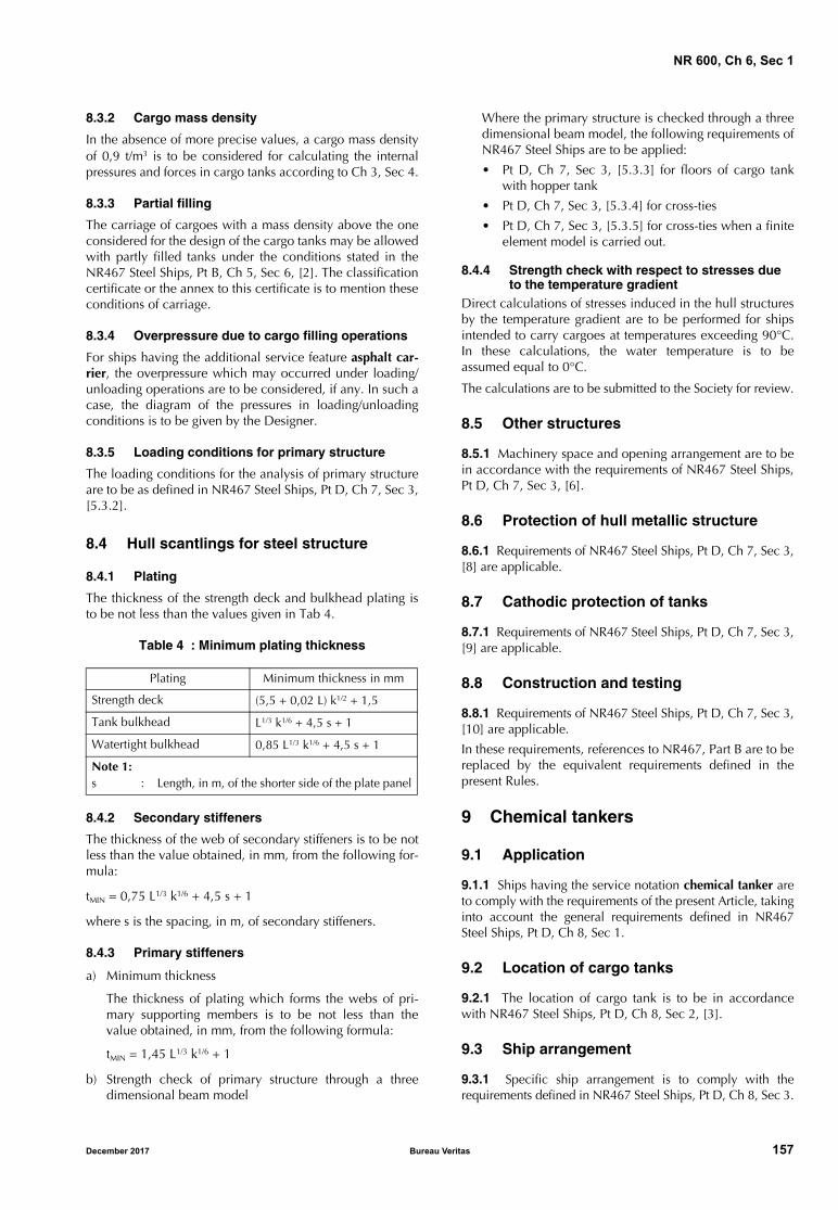
NR 600, Ch 6, Sec 1
8.3.2 Cargo mass density
In the absence of more precise values, a cargo mass densityof 0,9 t/m3 is to be considered for calculating the internalpressures and forces in cargo tanks according to Ch 3, Sec 4.
8.3.3 Partial filling
The carriage of cargoes with a mass density above the oneconsidered for the design of the cargo tanks may be allowedwith partly filled tanks under the conditions stated in theNR467 Steel Ships, Pt B, Ch 5, Sec 6, [2]. The classificationcertificate or the annex to this certificate is to mention theseconditions of carriage.
8.3.4 Overpressure due to cargo filling operations
For ships having the additional service feature asphalt car-rier, the overpressure which may occurred under loading/unloading operations are to be considered, if any. In such acase, the diagram of the pressures in loading/unloadingconditions is to be given by the Designer.
8.3.5 Loading conditions for primary structure
The loading conditions for the analysis of primary structureare to be as defined in NR467 Steel Ships, Pt D, Ch 7, Sec 3,[5.3.2].
8.4 Hull scantlings for steel structure
8.4.1 Plating
The thickness of the strength deck and bulkhead plating isto be not less than the values given in Tab 4.
Table 4 : Minimum plating thickness
8.4.2 Secondary stiffeners
The thickness of the web of secondary stiffeners is to be notless than the value obtained, in mm, from the following for-mula:
tMIN = 0,75 L1/3 k1/6 + 4,5 s + 1
where s is the spacing, in m, of secondary stiffeners.
8.4.3 Primary stiffeners
a) Minimum thickness
The thickness of plating which forms the webs of pri-mary supporting members is to be not less than thevalue obtained, in mm, from the following formula:
tMIN = 1,45 L1/3 k1/6 + 1
b) Strength check of primary structure through a threedimensional beam model
Where the primary structure is checked through a threedimensional beam model, the following requirements ofNR467 Steel Ships are to be applied:
• Pt D, Ch 7, Sec 3, [5.3.3] for floors of cargo tankwith hopper tank
• Pt D, Ch 7, Sec 3, [5.3.4] for cross-ties
• Pt D, Ch 7, Sec 3, [5.3.5] for cross-ties when a finiteelement model is carried out.
8.4.4 Strength check with respect to stresses due to the temperature gradient
Direct calculations of stresses induced in the hull structuresby the temperature gradient are to be performed for shipsintended to carry cargoes at temperatures exceeding 90°C.In these calculations, the water temperature is to beassumed equal to 0°C.
The calculations are to be submitted to the Society for review.
8.5 Other structures
8.5.1 Machinery space and opening arrangement are to bein accordance with the requirements of NR467 Steel Ships,Pt D, Ch 7, Sec 3, [6].
8.6 Protection of hull metallic structure
8.6.1 Requirements of NR467 Steel Ships, Pt D, Ch 7, Sec 3,[8] are applicable.
8.7 Cathodic protection of tanks
8.7.1 Requirements of NR467 Steel Ships, Pt D, Ch 7, Sec 3,[9] are applicable.
8.8 Construction and testing
8.8.1 Requirements of NR467 Steel Ships, Pt D, Ch 7, Sec 3,[10] are applicable.
In these requirements, references to NR467, Part B are to bereplaced by the equivalent requirements defined in thepresent Rules.
9 Chemical tankers
9.1 Application
9.1.1 Ships having the service notation chemical tanker areto comply with the requirements of the present Article, takinginto account the general requirements defined in NR467Steel Ships, Pt D, Ch 8, Sec 1.
9.2 Location of cargo tanks
9.2.1 The location of cargo tank is to be in accordancewith NR467 Steel Ships, Pt D, Ch 8, Sec 2, [3].
9.3 Ship arrangement
9.3.1 Specific ship arrangement is to comply with therequirements defined in NR467 Steel Ships, Pt D, Ch 8, Sec 3.
Plating Minimum thickness in mm
Strength deck (5,5 + 0,02 L) k1/2 + 1,5
Tank bulkhead L1/3 k1/6 + 4,5 s + 1
Watertight bulkhead 0,85 L1/3 k1/6 + 4,5 s + 1
Note 1:s : Length, in m, of the shorter side of the plate panel
December 2017 Bureau Veritas 157
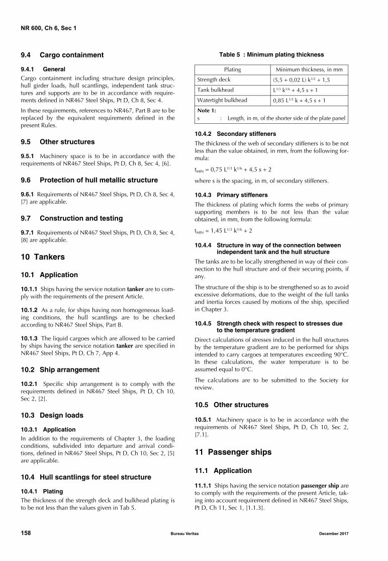
NR 600, Ch 6, Sec 1
9.4 Cargo containment
9.4.1 GeneralCargo containment including structure design principles,hull girder loads, hull scantlings, independent tank struc-tures and supports are to be in accordance with require-ments defined in NR467 Steel Ships, Pt D, Ch 8, Sec 4.
In these requirements, references to NR467, Part B are to bereplaced by the equivalent requirements defined in thepresent Rules.
9.5 Other structures
9.5.1 Machinery space is to be in accordance with therequirements of NR467 Steel Ships, Pt D, Ch 8, Sec 4, [6].
9.6 Protection of hull metallic structure
9.6.1 Requirements of NR467 Steel Ships, Pt D, Ch 8, Sec 4,[7] are applicable.
9.7 Construction and testing
9.7.1 Requirements of NR467 Steel Ships, Pt D, Ch 8, Sec 4,[8] are applicable.
10 Tankers
10.1 Application
10.1.1 Ships having the service notation tanker are to com-ply with the requirements of the present Article.
10.1.2 As a rule, for ships having non homogeneous load-ing conditions, the hull scantlings are to be checkedaccording to NR467 Steel Ships, Part B.
10.1.3 The liquid cargoes which are allowed to be carriedby ships having the service notation tanker are specified inNR467 Steel Ships, Pt D, Ch 7, App 4.
10.2 Ship arrangement
10.2.1 Specific ship arrangement is to comply with therequirements defined in NR467 Steel Ships, Pt D, Ch 10,Sec 2, [2].
10.3 Design loads
10.3.1 ApplicationIn addition to the requirements of Chapter 3, the loadingconditions, subdivided into departure and arrival condi-tions, defined in NR467 Steel Ships, Pt D, Ch 10, Sec 2, [5]are applicable.
10.4 Hull scantlings for steel structure
10.4.1 PlatingThe thickness of the strength deck and bulkhead plating isto be not less than the values given in Tab 5.
Table 5 : Minimum plating thickness
10.4.2 Secondary stiffeners
The thickness of the web of secondary stiffeners is to be notless than the value obtained, in mm, from the following for-mula:
tMIN = 0,75 L1/3 k1/6 + 4,5 s + 2
where s is the spacing, in m, of secondary stiffeners.
10.4.3 Primary stiffeners
The thickness of plating which forms the webs of primarysupporting members is to be not less than the valueobtained, in mm, from the following formula:
tMIN = 1,45 L1/3 k1/6 + 2
10.4.4 Structure in way of the connection between independent tank and the hull structure
The tanks are to be locally strengthened in way of their con-nection to the hull structure and of their securing points, ifany.
The structure of the ship is to be strengthened so as to avoidexcessive deformations, due to the weight of the full tanksand inertia forces caused by motions of the ship, specifiedin Chapter 3.
10.4.5 Strength check with respect to stresses due to the temperature gradient
Direct calculations of stresses induced in the hull structuresby the temperature gradient are to be performed for shipsintended to carry cargoes at temperatures exceeding 90°C.In these calculations, the water temperature is to beassumed equal to 0°C.
The calculations are to be submitted to the Society forreview.
10.5 Other structures
10.5.1 Machinery space is to be in accordance with therequirements of NR467 Steel Ships, Pt D, Ch 10, Sec 2,[7.1].
11 Passenger ships
11.1 Application
11.1.1 Ships having the service notation passenger ship areto comply with the requirements of the present Article, tak-ing into account requirement defined in NR467 Steel Ships,Pt D, Ch 11, Sec 1, [1.1.3].
Plating Minimum thickness, in mm
Strength deck (5,5 + 0,02 L) k1/2 + 1,5
Tank bulkhead L1/3 k1/6 + 4,5 s + 1
Watertight bulkhead 0,85 L1/3 k + 4,5 s + 1
Note 1:s : Length, in m, of the shorter side of the plate panel
158 Bureau Veritas December 2017

NR 600, Ch 6, Sec 1
11.2 Ship arrangement
11.2.1 Specific ship arrangement is to comply with therequirements defined in NR467 Steel Ships, Pt D, Ch 11,Sec 2.
11.3 Hull girder strength
11.3.1 Strength deck
The contribution to the longitudinal strength of the hullstructures up to the strength deck is to be assessed on a caseby case basis in the following cases:
• when the size of openings in the side shell and/or longi-tudinal bulkheads located below the deck assumed bythe Designer as the strength deck decrease significantlythe capability of the plating to transmit shear forces tothe strength deck.
• when the ends of superstructures which are required tocontribute to longitudinal strength may be considerednot effectively connected to the hull structures in way.
11.4 Hull scantlings
11.4.1 Plating
As a rule, the thickness of the inner bottom, side andweather strength deck plating for steel structure is to be notless than the values given in Tab 6.
Table 6 : Minimum plate thickness
11.4.2 Side shell plating
If a complete deck does exist at a distance from the free-board deck exceeding 2 times the standard height of super-structures as defined in Ch 1, Sec 1, [4.12.4], the side shellplating located between this complete deck and thestrength deck may be taken not greater than the thickness ofdeckhouse sides defined in Ch 5, Sec 1.
12 Ro-ro passenger ships
12.1 Application
12.1.1 Ships having the service notation ro-ro passengership are to comply with the requirements of the presentArticle, taking into account the requirement defined inNR467 Steel Ships, Pt D, Ch 12, Sec 1, [1.1.3].
12.2 Ship arrangement
12.2.1 Specific ship arrangement is to comply with therequirements defined in NR467 Steel Ships, Pt D, Ch 12,Sec 2, [12.4.2]
12.3 Structure design principles
12.3.1 Specific structure design principles are to complywith the requirements defined in NR467 Steel Ships, Pt D,Ch 12, Sec 3, [3].
12.3.2 When deemed necessary by the Society, the behav-iour of the ship primary structural members under rackingeffect due to transverse forces induced by transverse accel-erations is to be investigated by direct calculation on a caseby case basis.
12.4 Design loads
12.4.1 General
Loads on deck and exposed deck specified in NR467 SteelShips, Pt D, Ch 12, Sec 3, [4] are to be considered.
12.4.2 Lowest 0,5 m of bulkheads forming vertical division along escape route in accommodation
The pressures transmitted to the structures belonging to low-est 0,5 m of bulkheads and other partitions forming verticaldivisions along escape routes are to be obtained, in kN/m2,as specified in Ch 3, Sec 4, [4.2], where the value pS is to betaken not less than 1,5 kN/m2 to allow them to be used aswalking surfaces from the side of the escape route with theship at large angles of heel.
12.5 Hull girder strength
12.5.1 Strength deck
The contribution to the longitudinal strength of the hullstructures up to the strength deck is to be assessed on a caseby case basis in the following cases:
• when the size of openings in the side shell and/or longi-tudinal bulkheads located below the deck assumed bythe Designer as the strength deck decrease significantlythe capability of the plating to transmit shear forces tothe strength deck
• when the ends of superstructures which are required tocontribute to longitudinal strength may be considerednot effectively connected to the hull structures in way.
12.6 Hull scantlings
12.6.1 Plating
a) Minimum thickness:
As a rule, the thickness of the inner bottom, side andweather strength deck plating for steel structure is to benot less than the values given in Tab 7
Plating Minimum thickness (mm)
Inner bottom outside engine room
2,0+0,02Lk1/2+4,5s
Side• below freeboard deck• between freeboard deck
and strength deck
2,1+0,028Lk1/2+4,5s
Weather deck and trunk deck 2,2k1/2+2,1+s
Balconies 0,3+0,004Lk1/2+4,5s
k, s : Material factor and length, in m, of the shorter side of the plate panel.
December 2017 Bureau Veritas 159
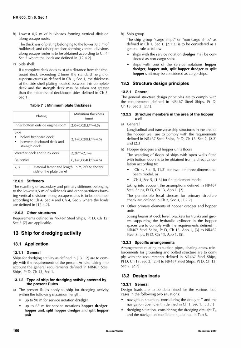
NR 600, Ch 6, Sec 1
b) Lowest 0,5 m of bulkheads forming vertical divisionalong escape route:
The thickness of plating belonging to the lowest 0,5 m ofbulkheads and other partitions forming vertical divisionsalong escape routes is to be obtained according to Ch 4,Sec 3 where the loads are defined in [12.4.2]
c) Side shell:
If a complete deck does exist at a distance from the free-board deck exceeding 2 times the standard height ofsuperstructures as defined in Ch 1, Sec 1, the thicknessof the side shell plating located between this completedeck and the strength deck may be taken not greaterthan the thickness of deckhouse sides defined in Ch 5,Sec 1.
Table 7 : Minimum plate thickness
12.6.2 StiffenersThe scantling of secondary and primary stiffeners belongingto the lowest 0,5 m of bulkheads and other partitions form-ing vertical divisions along escape routes is to be obtainedaccording to Ch 4, Sec 4 and Ch 4, Sec 5 where the loadsare defined in [12.4.2].
12.6.3 Other structuresRequirements defined in NR467 Steel Ships, Pt D, Ch 12,Sec 3 [7] are applicable.
13 Ship for dredging activity
13.1 Application
13.1.1 GeneralShips for dredging activity as defined in [13.1.2] are to com-ply with the requirements of the present Article, taking intoaccount the general requirements defined in NR467 SteelShips, Pt D, Ch 13, Sec 1.
13.1.2 Type of ship for dredging activity covered by the present Rules
a) The present Rules apply to ship for dredging activitywithin the following maximum length:
• up to 90 m for service notation dredger
• up to 65 m for service notations hopper dredger,hopper unit, split hopper dredger and split hopperunit
b) Ship group
The ship group “cargo ships” or “non-cargo ships” asdefined in Ch 1, Sec 1, [2.1.2] is to be considered as ageneral rule as follow:
• ships with the service notation dredger may be con-sidered as non-cargo ships
• ships with one of the service notations hopperdredger, hopper unit, split hopper dredger or splithopper unit may be considered as cargo ships.
13.2 Structure design principles
13.2.1 GeneralThe general structure design principles are to comply withthe requirements defined in NR467 Steel Ships, Pt D,Ch 13, Sec 2, [2.1].
13.2.2 Structure members in the area of the hopper well
a) General
Longitudinal and transverse ship structures in the area ofthe hopper well are to comply with the requirementsdefined in NR467 Steel Ships, Pt D, Ch 13, Sec 2, [2.2]and [2.3]
b) Hopper dredgers and hopper units floors
The scantling of floors of ships with open wells fittedwith bottom doors is to be obtained from a direct calcu-lation according to:
• Ch 4, Sec 5, [1.2] for two- or three-dimensionalbeam model, or
• Ch 4, Sec 5, [1.3] for finite element model
taking into account the assumptions defined in NR467Steel Ships, Pt D, Ch 13, App 1, [2].
The permissible local stresses for primary structurecheck are defined in Ch 2, Sec 3, [2.2.2]
c) Other primary elements of hopper dredger and hopperunits
Strong beams at deck level, brackets for trunks and gird-ers supporting the hydraulic cylinder in the hopperspaces are to comply with the requirements defined inNR467 Steel Ships, Pt D, Ch 13, App 1, [3] to NR467Steel Ships, Pt D, Ch 13, App 1, [5].
13.2.3 Specific arrangementsArrangements relating to suction pipes, chafing areas, rein-forcements for grounding and bolted structure are to com-ply with the requirements defined in NR467 Steel Ships,Pt D, Ch 13, Sec 2, [2.4] to NR467 Steel Ships, Pt D, Ch 13,Sec 2, [2.7].
13.3 Design loads
13.3.1 GeneralDesign loads are to be determined for the various loadcases in the following two situations:
• navigation situation, considering the draught T and thenavigation coefficient n defined in Ch 1, Sec 1, [3.1.1]
• dredging situation, considering the dredging draught TD
and the navigation coefficient nD defined in Tab 8.
PlatingMinimum thickness
(mm)
Inner bottom outside engine room 2,0+0,02Lk1/2+4,5s
Side• below freeboard deck• between freeboard deck and
strength deck
2,1+0,028Lk1/2+4,5s
Weather deck and trunk deck 2,2k1/2+2,1+s
Balconies 0,3+0,004Lk1/2+4,5s
k, s : Material factor and length, in m, of the shorter side of the plate panel
160 Bureau Veritas December 2017
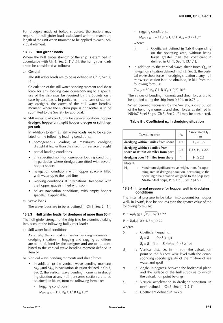
NR 600, Ch 6, Sec 1
For dredgers made of bolted structure, the Society mayrequire the hull girder loads calculated with the maximumlength of the unit when mounted to be applied to each indi-vidual element.
13.3.2 Hull girder loadsWhere the hull girder strength of the ship is examined inaccordance with Ch 4, Sec 2, [1.1.3], the hull girder loadsare to be considered as follows:
a) General
The still water loads are to be as defined in Ch 3, Sec 2,[4].
Calculation of the still water bending moment and shearforce for any loading case corresponding to a specialuse of the ship may be required by the Society on acase-by-case basis. In particular, in the case of station-ary dredgers, the curve of the still water bendingmoment, where the suction pipe is horizontal, is to besubmitted to the Society for approval.
b) Still water load conditions for service notations hopperdredger, hopper unit, split hopper dredger or split hop-per unit
In addition to item a), still water loads are to be calcu-lated for the following loading conditions:
• homogeneous loading at maximum dredgingdraught if higher than the maximum service draught
• partial loading conditions
• any specified non-homogeneous loading condition,in particular where dredgers are fitted with severalhopper spaces
• navigation conditions with hopper space(s) filledwith water up to the load line
• working conditions at international freeboard withthe hopper space(s) filled with spoil
• ballast navigation conditions, with empty hopperspace(s), if applicable.
c) Wave loads
The wave loads are to be as defined in Ch 3, Sec 2, [5].
13.3.3 Hull girder loads for dredgers of more than 65 mThe hull girder strength of the ship is to be examined takinginto account the following hull girder loads:
a) Still water load conditions
As a rule, the vertical still water bending moments indredging situation in hogging and sagging conditionsare to be defined by the designer and are to be com-bined to the vertical wave bending moment defined initem b).
b) Vertical wave bending moments and shear forces
• In addition to the vertical wave bending momentsMWH and MWS in navigation situation defined in Ch 3,Sec 2, the vertical wave bending moments in dredg-ing situation at any hull transverse section are to beobtained, in kN⋅m, from the following formulae:
- hogging conditions:
MWV, H, D = 190 nD C L2 B CB 10−3
- sagging conditions:
MWV, S, D = − 110 nD C L2 B (CB + 0,7) 10−3
where:
nD : Coefficient defined in Tab 8 dependingon the operating area, without beingtaken greater than the coefficient ndefined in Ch 1, Sec 1, [3.1.1].
• In addition to the vertical wave shear force QW innavigation situation defined in Ch 3, Sec 2, the verti-cal wave shear force in dredging situation at any hulltransverse section is to be obtained, in kN, from thefollowing formula:
QW, D = 30 nD C L B (CB + 0,7) 10−2
The values of bending moments and shear forces are tobe applied along the ship from 0,30 L to 0,75 L.
When deemed necessary by the Society, a distributionof the bending moments and shear forces as defined inNR467 Steel Ships, Ch 5, Sec 2, [3] may be considered.
Table 8 : Coefficient nD in dredging situation
13.3.4 Internal pressure for hopper well in dredging conditions
The internal pressure to be taken into account for hopperwell, in kN/m2, is to be not less than the greater value of thefollowing formulae:
where:
δ1 : Coefficient equal to:
δ1 = δ for δ < 1,4
δ1 = δ + (1,4 − δ) sin2α for δ ≥ 1,4
dD : Vertical distance, in m, from the calculationpoint to the highest weir level with the corre-sponding specific gravity of the mixture of seawater and spoil
α : Angle, in degrees, between the horizontal planeand the surface of the hull structure to whichthe calculation point belongs
az : Vertical acceleration in dredging condition, inm/s2, defined in Ch 3, Sec 4, [2.2.1]
nD : Coefficient defined in Tab 8.
Operating area nDAssociated HS,
in m
dredging within 8 miles from shore 1/3 HS < 1,5
dredging within 15 miles from shore or within 20 miles from port
2/3 1,5 ≤ HS < 2,5
dredging over 15 miles from shore 1 HS ≥ 2,5
Note 1:HS : Maximum significant wave height, in m, for oper-
ating area in dredging situation, according to theoperating area notation assigned to the ship (seeNR467 Steel Ships, Pt A, Ch 1, Sec 2 [4.6]).
P δ1dD g a2z nD
2++( ) 22≥=
P δ1dD 10 4 5nD,+( ) 22≥=
December 2017 Bureau Veritas 161
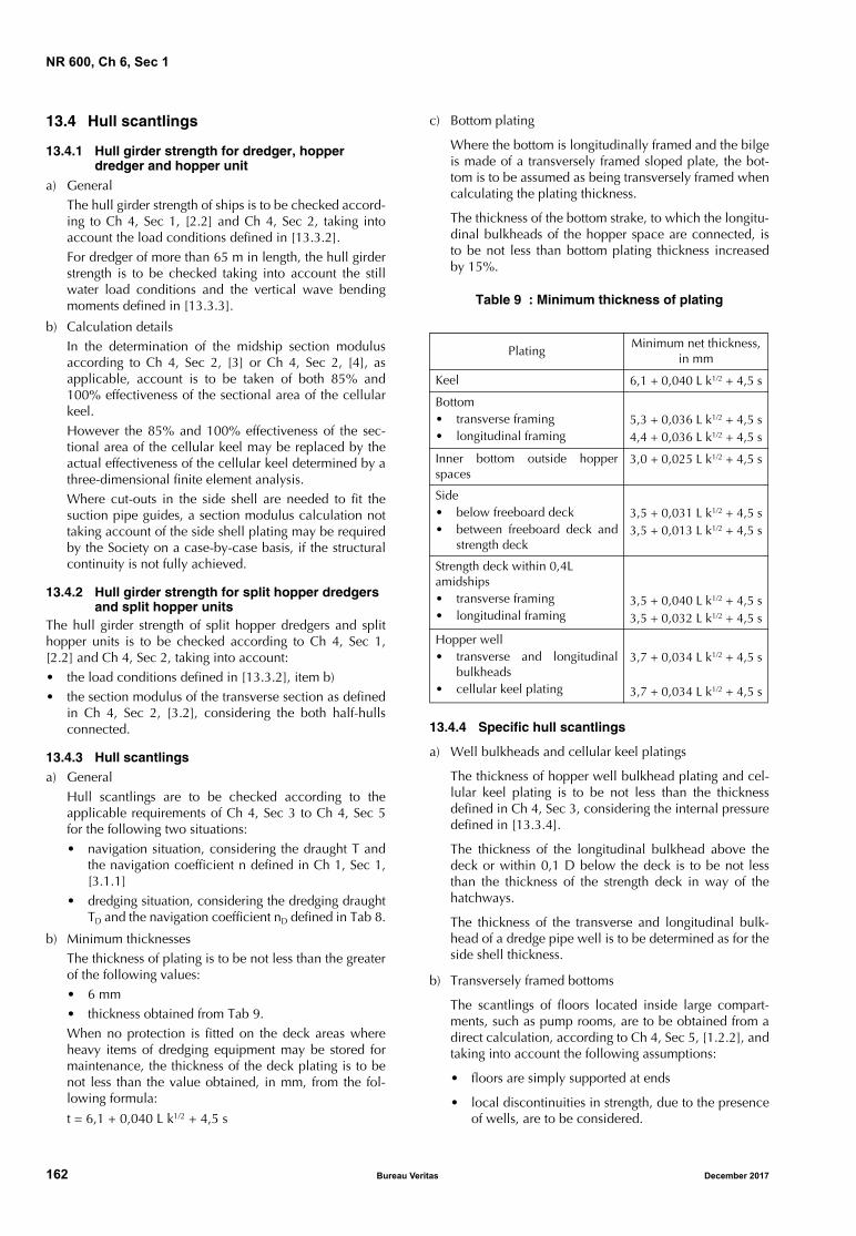
NR 600, Ch 6, Sec 1
13.4 Hull scantlings
13.4.1 Hull girder strength for dredger, hopper dredger and hopper unit
a) GeneralThe hull girder strength of ships is to be checked accord-ing to Ch 4, Sec 1, [2.2] and Ch 4, Sec 2, taking intoaccount the load conditions defined in [13.3.2].For dredger of more than 65 m in length, the hull girderstrength is to be checked taking into account the stillwater load conditions and the vertical wave bendingmoments defined in [13.3.3].
b) Calculation detailsIn the determination of the midship section modulusaccording to Ch 4, Sec 2, [3] or Ch 4, Sec 2, [4], asapplicable, account is to be taken of both 85% and100% effectiveness of the sectional area of the cellularkeel.However the 85% and 100% effectiveness of the sec-tional area of the cellular keel may be replaced by theactual effectiveness of the cellular keel determined by athree-dimensional finite element analysis.Where cut-outs in the side shell are needed to fit thesuction pipe guides, a section modulus calculation nottaking account of the side shell plating may be requiredby the Society on a case-by-case basis, if the structuralcontinuity is not fully achieved.
13.4.2 Hull girder strength for split hopper dredgers and split hopper units
The hull girder strength of split hopper dredgers and splithopper units is to be checked according to Ch 4, Sec 1,[2.2] and Ch 4, Sec 2, taking into account:• the load conditions defined in [13.3.2], item b)• the section modulus of the transverse section as defined
in Ch 4, Sec 2, [3.2], considering the both half-hullsconnected.
13.4.3 Hull scantlingsa) General
Hull scantlings are to be checked according to theapplicable requirements of Ch 4, Sec 3 to Ch 4, Sec 5for the following two situations:• navigation situation, considering the draught T and
the navigation coefficient n defined in Ch 1, Sec 1,[3.1.1]
• dredging situation, considering the dredging draughtTD and the navigation coefficient nD defined in Tab 8.
b) Minimum thicknessesThe thickness of plating is to be not less than the greaterof the following values:• 6 mm• thickness obtained from Tab 9.When no protection is fitted on the deck areas whereheavy items of dredging equipment may be stored formaintenance, the thickness of the deck plating is to benot less than the value obtained, in mm, from the fol-lowing formula:
t = 6,1 + 0,040 L k1/2 + 4,5 s
c) Bottom plating
Where the bottom is longitudinally framed and the bilgeis made of a transversely framed sloped plate, the bot-tom is to be assumed as being transversely framed whencalculating the plating thickness.
The thickness of the bottom strake, to which the longitu-dinal bulkheads of the hopper space are connected, isto be not less than bottom plating thickness increasedby 15%.
Table 9 : Minimum thickness of plating
13.4.4 Specific hull scantlings
a) Well bulkheads and cellular keel platings
The thickness of hopper well bulkhead plating and cel-lular keel plating is to be not less than the thicknessdefined in Ch 4, Sec 3, considering the internal pressuredefined in [13.3.4].
The thickness of the longitudinal bulkhead above thedeck or within 0,1 D below the deck is to be not lessthan the thickness of the strength deck in way of thehatchways.
The thickness of the transverse and longitudinal bulk-head of a dredge pipe well is to be determined as for theside shell thickness.
b) Transversely framed bottoms
The scantlings of floors located inside large compart-ments, such as pump rooms, are to be obtained from adirect calculation, according to Ch 4, Sec 5, [1.2.2], andtaking into account the following assumptions:
• floors are simply supported at ends
• local discontinuities in strength, due to the presenceof wells, are to be considered.
PlatingMinimum net thickness,
in mm
Keel 6,1 + 0,040 L k1/2 + 4,5 s
Bottom• transverse framing• longitudinal framing
5,3 + 0,036 L k1/2 + 4,5 s4,4 + 0,036 L k1/2 + 4,5 s
Inner bottom outside hopperspaces
3,0 + 0,025 L k1/2 + 4,5 s
Side• below freeboard deck• between freeboard deck and
strength deck
3,5 + 0,031 L k1/2 + 4,5 s3,5 + 0,013 L k1/2 + 4,5 s
Strength deck within 0,4Lamidships• transverse framing• longitudinal framing
3,5 + 0,040 L k1/2 + 4,5 s3,5 + 0,032 L k1/2 + 4,5 s
Hopper well• transverse and longitudinal
bulkheads• cellular keel plating
3,7 + 0,034 L k1/2 + 4,5 s
3,7 + 0,034 L k1/2 + 4,5 s
162 Bureau Veritas December 2017
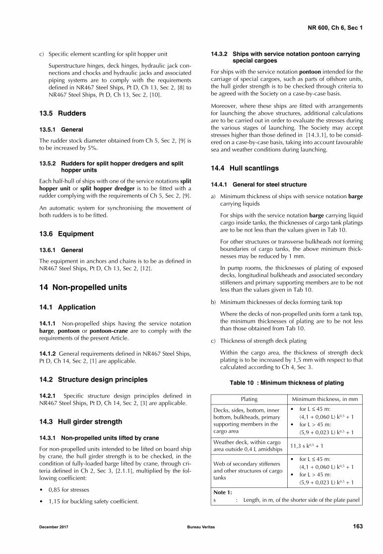
NR 600, Ch 6, Sec 1
c) Specific element scantling for split hopper unit
Superstructure hinges, deck hinges, hydraulic jack con-nections and chocks and hydraulic jacks and associatedpiping systems are to comply with the requirementsdefined in NR467 Steel Ships, Pt D, Ch 13, Sec 2, [8] toNR467 Steel Ships, Pt D, Ch 13, Sec 2, [10].
13.5 Rudders
13.5.1 General
The rudder stock diameter obtained from Ch 5, Sec 2, [9] isto be increased by 5%.
13.5.2 Rudders for split hopper dredgers and split hopper units
Each half-hull of ships with one of the service notations splithopper unit or split hopper dredger is to be fitted with arudder complying with the requirements of Ch 5, Sec 2, [9].
An automatic system for synchronising the movement ofboth rudders is to be fitted.
13.6 Equipment
13.6.1 General
The equipment in anchors and chains is to be as defined inNR467 Steel Ships, Pt D, Ch 13, Sec 2, [12].
14 Non-propelled units
14.1 Application
14.1.1 Non-propelled ships having the service notationbarge, pontoon or pontoon-crane are to comply with therequirements of the present Article.
14.1.2 General requirements defined in NR467 Steel Ships,Pt D, Ch 14, Sec 2, [1] are applicable.
14.2 Structure design principles
14.2.1 Specific structure design principles defined inNR467 Steel Ships, Pt D, Ch 14, Sec 2, [3] are applicable.
14.3 Hull girder strength
14.3.1 Non-propelled units lifted by crane
For non-propelled units intended to be lifted on board shipby crane, the hull girder strength is to be checked, in thecondition of fully-loaded barge lifted by crane, through cri-teria defined in Ch 2, Sec 3, [2.1.1], multiplied by the fol-lowing coefficient:
• 0,85 for stresses
• 1,15 for buckling safety coefficient.
14.3.2 Ships with service notation pontoon carrying special cargoes
For ships with the service notation pontoon intended for thecarriage of special cargoes, such as parts of offshore units,the hull girder strength is to be checked through criteria tobe agreed with the Society on a case-by-case basis.
Moreover, where these ships are fitted with arrangementsfor launching the above structures, additional calculationsare to be carried out in order to evaluate the stresses duringthe various stages of launching. The Society may acceptstresses higher than those defined in [14.3.1], to be consid-ered on a case-by-case basis, taking into account favourablesea and weather conditions during launching.
14.4 Hull scantlings
14.4.1 General for steel structure
a) Minimum thickness of ships with service notation bargecarrying liquids
For ships with the service notation barge carrying liquidcargo inside tanks, the thicknesses of cargo tank platingsare to be not less than the values given in Tab 10.
For other structures or transverse bulkheads not formingboundaries of cargo tanks, the above minimum thick-nesses may be reduced by 1 mm.
In pump rooms, the thicknesses of plating of exposeddecks, longitudinal bulkheads and associated secondarystiffeners and primary supporting members are to be notless than the values given in Tab 10.
b) Minimum thicknesses of decks forming tank top
Where the decks of non-propelled units form a tank top,the minimum thicknesses of plating are to be not lessthan those obtained from Tab 10.
c) Thickness of strength deck plating
Within the cargo area, the thickness of strength deckplating is to be increased by 1,5 mm with respect to thatcalculated according to Ch 4, Sec 3.
Table 10 : Minimum thickness of plating
Plating Minimum thickness, in mm
Decks, sides, bottom, inner bottom, bulkheads, primary supporting members in the cargo area
• for L ≤ 45 m:(4,1 + 0,060 L) k0,5 + 1
• for L > 45 m:(5,9 + 0,023 L) k0,5 + 1
Weather deck, within cargo area outside 0,4 L amidships
11,3 s k0,5 + 1
Web of secondary stiffeners and other structures of cargo tanks
• for L ≤ 45 m:(4,1 + 0,060 L) k0,5 + 1
• for L > 45 m:(5,9 + 0,023 L) k0,5 + 1
Note 1:s : Length, in m, of the shorter side of the plate panel
December 2017 Bureau Veritas 163
NR 600, Ch 6, Sec 1
14.4.2 Scantling of deck secondary stiffeners subjected to maximum allowable loads defined by the Designer
For longitudinal secondary deck stiffeners contributing tothe global strength and subjected to maximum allowabledeck loads defined by the Designer, the section modulus Z,in cm3, and the shear area Ash, in cm2, may be taken not lessthan the values defined in Ch 4, App 2, [3], taking intoaccount a permissible local scantling stress σad, in N/mm2,equal to:
where:
Ry, σA : Defined in Ch 4, App 2.
14.4.3 Hull scantlings of non-propelled units with the service notation pontoon fitted with arrangements and systems for launching operations
a) Additional information
In addition to the documentation specified in Ch 1, Sec 1,[7], the following information is to be submitted to theSociety:
• maximum draught of the ship during the differentstages of the launching operations
• operating loads and their distribution
• launching cradle location.
b) Scantlings of plating, secondary and primary stiffeners
In applying the formulae in Chapter 4, T is to be takenequal to the maximum draught during the differentstages of launching and taking into account, whereappropriate, the differential static pressure.
c) Deck scantlings
The scantlings of decks are to be in accordance withChapter 4, considering the maximum loads acting onthe launching cradle.
The thickness of deck plating in way of launch groundways is to be suitably increased if the cradle may beplaced in different positions.
The scantlings of decks in way of pivoting and end areasof the cradle are to be obtained through direct calcula-tions.
d) Launching cradles
The launching cradles are to be adequately connectedto deck structures and arranged, as far as possible, inway of longitudinal bulkheads or at least of girders.
14.4.4 Hull scantlings of non-propelled units with service notation pontoon-crane
Requirements defined in NR467 Steel Ships, Pt D, Ch 14,Sec 2, [5.3] are applicable.
14.5 Hull outfitting
14.5.1 Equipment
a) Manned non-propelled units
The equipment of anchors, chain cables and ropes to befitted on board manned non-propelled units is to com-ply with Ch 5, Sec 4.
Chain cables for anchors may be replaced by steel ropeshaving the same breaking load. The ropes are to be con-nected to the anchors by approximately 10 m of chaincable complying with Ch 5, Sec 4.
Non-propelled units continuously assisted by a tug mayhave only one anchor, complying with Ch 5, Sec 4, anda chain rope having length neither less than 75% of thelength obtained according to Ch 5, Sec 4, nor less than220 m.
b) Unmanned non-propelled units
For unmanned non-propelled units, the equipment isnot required for classification purposes. The scantlingsof anchors, chain cables and ropes to be fitted on boardare the responsibility of the Designer.
c) Towing arrangements
Non-propelled units are to be fitted with suitablearrangements for towing, with scantlings under theresponsibility of the Designer.
The Society may, at the specific request of the interestedparties, check the above arrangements and the associ-ated hull strengthening; to this end, the maximum pullfor which the arrangements are to be checked is to bespecified on the plans and documents submitted forapproval.
15 Fishing vessels
15.1 Application
15.1.1 Ships having the service notation fishing vessel areto comply with the requirements of the present Article.
15.2 Ship arrangement
15.2.1 Specific ship arrangement is to comply with therequirements defined in NR467 Steel Ships, Pt D, Ch 15,Sec 2.
For vessels less than 45 m in length, the collision bulkheadis to be located at a distance from the forward perpendicu-lar FPLL of not less than 5% of the length LLL of the ship andnot more than 5% of the length LLL + 1,35 m. For shipsgreater than 24 m in length, this distance is not to be lessthan 2 m.
15.3 Specific design loads
15.3.1 GeneralThe specific design loads defined in the present Article areto be taken into account in addition to the design loadsdefined in Chapter 3.
15.3.2 Fish hold
The design pressure pF, in kN/m2, to be considered for thescantling of fish holds, is to be obtained from the followingformula:
where:
σad 0 95Ry, 0.72σA–=
pF 7zTOP z–zTOP z0–---------------------- hTD=
164 Bureau Veritas December 2017
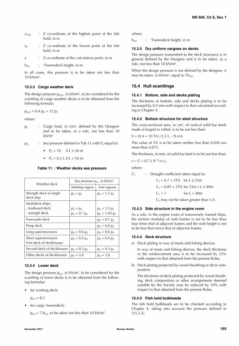
NR 600, Ch 6, Sec 1
zTOP : Z co-ordinate of the highest point of the fishhold, in m
z0 : Z co-ordinate of the lowest point of the fishhold, in m
z : Z co-ordinate of the calculation point, in m
hTD : ‘Tweendeck height, in m.
In all cases, this pressure is to be taken not less than10 kN/m2.
15.3.3 Cargo weather deck
The design pressure pWD , in kN/m2, to be considered for thescantling of cargo weather decks is to be obtained from thefollowing formula:
pWD = 0,4 pD + 12 pC
where:
pC : Cargo load, in t/m², defined by the Designerand to be taken, as a rule, not less than 10kN/m2
pD : Sea pressure defined in Tab 11 with P0 equal to:
• P0 = 10 if L ≤ 50 m
• P0 = 0,2 L if L > 50 m.
Table 11 : Weather decks sea pressure
15.3.4 Lower deck
The design pressure pLD, in kN/m2, to be considered for thescantling of lower decks is to be obtained from the follow-ing formulae:
• for working deck:
pLD = 8,5
• for cargo ‘tweendeck:
pLD = 7 hTD, to be taken not less than 10 kN/m2
where:
hTD : ‘Tweendeck height, in m.
15.3.5 Dry uniform cargoes on decks
The design pressure transmitted to the deck structures is ingeneral defined by the Designer and is to be taken, as arule, not less than 10 kN/m2.
When the design pressure is not defined by the designer, itmay be taken, in kN/m2, equal to 7hTD.
15.4 Hull scantlings
15.4.1 Bottom, side and decks plating
The thickness of bottom, side and decks plating is to beincreased by 0,5 mm with respect to that calculated accord-ing to Chapter 4.
15.4.2 Bottom structure for steel structure
The cross-sectional area, in cm2, of vertical solid bar keelsmade of forged or rolled, is to be not less than:
S = (0,4 + 10 T/L) (1,5 L − 9) n k
The value of T/L is to be taken neither less than 0,050 normore than 0,075.
The thickness, in mm, of solid bar keel is to be not less than:
t = (5 + 0,7 L k1/2) n cT
where:
CT : Draught coefficient taken equal to:
CT = 0,7 + 3T/L for L ≤ 25m
CT = 0,85 + 2T/L for 25m < L ≤ 40m
CT = 1 for L > 40m
CT may not be taken greater than 1,0.
15.4.3 Side structure in the engine room
As a rule, in the engine room of transversely framed ships,the section modulus of web frames is not to be less thanfour times that of adjacent frames and the web height is notto be less than twice that of adjacent frames.
15.4.4 Deck structure
a) Deck plating in way of masts and fishing devices
In way of masts and fishing devices, the deck thicknessin the reinforcement area is to be increased by 25%with respect to that obtained from the present Rules.
b) Deck plating protected by wood sheathing or deck com-position
The thickness of deck plating protected by wood sheath-ing, deck composition or other arrangements deemedsuitable by the Society may be reduced by 10% withrespect to that obtained from the present Rules.
15.4.5 Fish hold bulkheads
The fish hold bulkheads are to be checked according toChapter 4, taking into account the pressure defined in[15.3.2].
Weather deckSea pressure pD , in kN/m2
Midship region End regions
Strength deck of single deck ship
pD = p0 pD = 1,5 p0
Multideck ships:- freeboard deck- strength deck
pD = p0
pD = 0,7 p0
pD = 1,5 p0
pD = 1,05 p0
Forecastle deck pD = 0,7 p0
Poop deck pD = 0,6 p0
Long superstructures pD = 0,6 p0 pD = 0,6 p0
Short superstructuresFirst deck of deckhouses
pD = 0,4 p0 pD = 0,4 p0
Second deck of deckhouses pD = 0,3 p0 pD = 0,3 p0
Other decks of deckhouses pD = 3,0 pD = 3,0
December 2017 Bureau Veritas 165
NR 600, Ch 6, Sec 1
15.4.6 Aft ramp
As a rule, the thickness of the aft ramp are defined as follow:
a) Plating of the aft ramp and the lower part of the aft rampside:
The thickness of plating of the aft ramp and the lowerpart of the aft ramp side is to be increased by 2 mm withrespect to that calculated according to the present Rulesfor side plating with the same plate panel dimensions.
As a rule, the thickness of plating of the aft ramp and thelower part of the aft ramp side is to be not less than12 mm.
b) Plating of the upper part of the aft ramp side
The thickness of plating of the upper part of the aft rampside is to be not less than the value calculated accordingto the present Rules for side plating with the same platepanel dimensions.
15.5 Machinery casings
15.5.1 Arrangements
As a rule, ordinary stiffeners are to be located:
• at each frame, in longitudinal bulkheads
• at a distance of about 750 mm, in transverse bulkheads.
The ordinary stiffener spacing in portions of casings whichare particularly exposed to wave action is considered by theSociety on a case by case basis.
15.5.2 Engine room skylight coamings
a) Ships greater than 65 m in length:
Engine room skylight are to be in accordance withNR467 Steel Ships, Pt B, Ch 8, [7.2].
b) Ships less than 65 m in length:
If the engine room where skylights are fitted with opening-type covers providing light and air, the height of coamings isto be not less than:
• 900 mm, for skylights located on working decks
• 300 mm, for skylights located on superstructure decks.
The thickness of engine room skylight coamings is to be notless than 6 mm.
Where the height of engine room skylight coamings isgreater than 900 mm, the section modulus of vertical ordi-nary stiffeners with spacing not greater than 760 mm is tobe increased by 10% with respect to that obtained for verti-cal ordinary stiffeners of deckhouses.
15.5.3 Scantlings
The scantlings of plating and ordinary stiffeners are to benot less than those of plating and ordinary stiffeners ofsuperstructures and deckhouses. In any case, the thicknessof protected or unprotected casing bulkheads is to be notless than 5 mm.
15.6 Arrangement for hull and superstructure openings
15.6.1 General
Requirements defined in the present Article are applicableto ships less than 65 m in length.
The arrangement for hull and superstructure openings ofships greater than 65 m in length are to be in accordancewith NR467 Steel Ships.
15.6.2 Sidescuttles
Sidescuttles may not be fitted in such a position that theirsills are below a line drawn parallel to the sheer at side andhaving its lowest point 0,5 m above the summer load water-line.
No sidescuttles may be fitted in any spaces which areappropriated exclusively for the carriage of cargo.
15.6.3 Freeing ports
The freeing port area in bulwarks is to be not less than thevalue obtained from the formulae in NR467 Steel Ships, Pt B,Ch 8, Sec 10, [6].
For ships with L < 24 m and the navigation notation coastalarea, the freeing port area in bulwarks on each side of theship may be not less than the value obtained from the fol-lowing formula:
A = 0,035 B + AC
where:
B : Length, in m, of bulwark in the well, to be takennot greater than 0,7 L
AC : Area, in m2, to be taken, with its sign, equal to:
AC = 0,04 B (hB − 1,2) for hB > 1,2
AC = 0 for 0,9 ≤ hB ≤ 1,2
AC = 0,04 B (hB − 0,9) for hB < 0,9
hB : Mean height, in m, of bulwark in the well oflength B .
15.6.4 Openings in bulkheads of enclosed superstructures and other outer structures
All access openings in bulkheads of enclosed superstruc-tures and other outer structures (e.g. machinery casings)through which water can enter and endanger the ship are tobe fitted with doors of steel or other equivalent material,permanently and strongly attached to the bulkhead, andframed, stiffened and fitted so that the whole structure is ofequivalent strength to the unpierced bulkhead and weather-tight when closed. The doors are to be capable of beingoperated from both sides and generally to open outwards togive additional protection against wave impact.
These doors are to be fitted with gaskets and clampingdevices or other equivalent means permanently attached tothe bulkhead or to the door themselves.
Other openings are to be fitted with equivalent covers, per-manently attached in their proper position.
166 Bureau Veritas December 2017
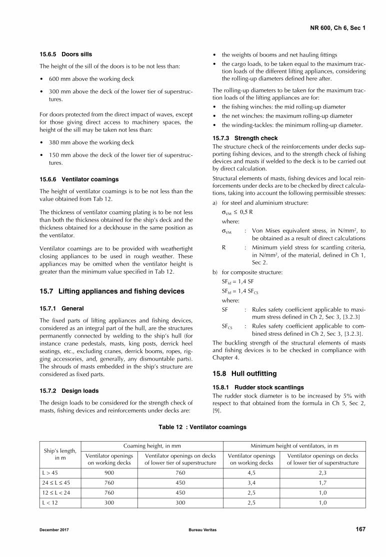
NR 600, Ch 6, Sec 1
15.6.5 Doors sills
The height of the sill of the doors is to be not less than:
• 600 mm above the working deck
• 300 mm above the deck of the lower tier of superstruc-tures.
For doors protected from the direct impact of waves, exceptfor those giving direct access to machinery spaces, theheight of the sill may be taken not less than:
• 380 mm above the working deck
• 150 mm above the deck of the lower tier of superstruc-tures.
15.6.6 Ventilator coamings
The height of ventilator coamings is to be not less than thevalue obtained from Tab 12.
The thickness of ventilator coaming plating is to be not lessthan both the thickness obtained for the ship’s deck and thethickness obtained for a deckhouse in the same position asthe ventilator.
Ventilator coamings are to be provided with weathertightclosing appliances to be used in rough weather. Theseappliances may be omitted when the ventilator height isgreater than the minimum value specified in Tab 12.
15.7 Lifting appliances and fishing devices
15.7.1 General
The fixed parts of lifting appliances and fishing devices,considered as an integral part of the hull, are the structurespermanently connected by welding to the ship’s hull (forinstance crane pedestals, masts, king posts, derrick heelseatings, etc., excluding cranes, derrick booms, ropes, rig-ging accessories, and, generally, any dismountable parts).The shrouds of masts embedded in the ship’s structure areconsidered as fixed parts.
15.7.2 Design loads
The design loads to be considered for the strength check ofmasts, fishing devices and reinforcements under decks are:
• the weights of booms and net hauling fittings
• the cargo loads, to be taken equal to the maximum trac-tion loads of the different lifting appliances, consideringthe rolling-up diameters defined here after.
The rolling-up diameters to be taken for the maximum trac-tion loads of the lifting appliances are for:
• the fishing winches: the mid rolling-up diameter
• the net winches: the maximum rolling-up diameter
• the winding-tackles: the minimum rolling-up diameter.
15.7.3 Strength checkThe structure check of the reinforcements under decks sup-porting fishing devices, and to the strength check of fishingdevices and masts if welded to the deck is to be carried outby direct calculation.
Structural elements of masts, fishing devices and local rein-forcements under decks are to be checked by direct calcula-tions, taking into account the following permissible stresses:
a) for steel and aluminium structure:
σVM ≤ 0,5 Rwhere:
σVM : Von Mises equivalent stress, in N/mm2, tobe obtained as a result of direct calculations
R : Minimum yield stress for scantling criteria,in N/mm2, of the material, defined in Ch 1,Sec 2.
b) for composite structure:
SFfd = 1,4 SF
SFfd = 1,4 SFCS
where:
SF : Rules safety coefficient applicable to maxi-mum stress defined in Ch 2, Sec 3, [3.2.3]
SFCS : Rules safety coefficient applicable to com-bined stress defined in Ch 2, Sec 3, [3.2.3].
The buckling strength of the structural elements of mastsand fishing devices is to be checked in compliance withChapter 4.
15.8 Hull outfitting
15.8.1 Rudder stock scantlingsThe rudder stock diameter is to be increased by 5% withrespect to that obtained from the formula in Ch 5, Sec 2,[9].
Table 12 : Ventilator coamings
Ship’s length, in m
Coaming height, in mm Minimum height of ventilators, in m
Ventilator openings on working decks
Ventilator openings on decksof lower tier of superstructure
Ventilator openings on working decks
Ventilator openings on decksof lower tier of superstructure
L > 45 900 760 4,5 2,3
24 ≤ L ≤ 45 760 450 3,4 1,7
12 ≤ L < 24 760 450 2,5 1,0
L < 12 300 300 2,5 1,0
December 2017 Bureau Veritas 167
NR 600, Ch 6, Sec 1
15.8.2 Propeller shaft bracketsPropeller shaft brackets are to be in accordance with Ch 5,Sec 2, [12].
For ships less than 30 m in length, single arm propeller shaftbrackets may be fitted.
15.8.3 EquipmentThe equipment in chain and anchor for ships having the ser-vice notation fishing vessel is defined in Ch 5, Sec 4.
Equipment in anchors and cables defined in Ch 5, Sec 4 maybe reduced on a case-by-case basis. Nevertheless, it belongsto the Designer and/or shipyard to submit all the relevantinformation demonstrating that reduced equipment - its con-figuration - and all its components, fully copes with theanchoring forces most frequently encountered during service.
For ships of special design or for ships engaged in specialservices or on special voyage, the Society may consideranchoring equipment other than defined in the present Arti-cle and in Ch 5, Sec 4.
As an alternative to the stud link chain cables calculated inCh 5, Sec 4, [3.2], wire ropes may be used in the followingcases:
• wire ropes for both the anchors, for ship’s length lessthan 30 m
• wire rope for one of the two anchors, for ship’s lengthbetween 30 m and 40 m.
The wire ropes above are to have a total length equal to 1,5times the corresponding required length of stud link chaincables, obtained from Ch 5, Sec 4, [3.2], and a minimumbreaking load equal to that given for the corresponding studlink chain.
A short length of chain cable is to be fitted between the wirerope and the anchor, having a length equal to 12,5 m or thedistance from the anchor in the stowed position to thewinch, whichever is the lesser.
When chain cables are replaced by trawl warps, the anchoris to be positioned on the forecastle deck so that it may bereadily cast after it has been shackled to the trawl warp.Chocks or rollers are to be fitted at suitable locations, alongthe path of the trawl warps, between the winch and themooring chocks.
15.9 Protection of hull metallic structure
15.9.1 Protection of decks by wood sheathingBefore fitting the wood sheathing, deck plating is to be pro-tected with suitable protective coating.
The thickness of wood sheathing of decks is to be not lessthan:
• 65 mm, if made of pine
• 50 mm, if made of hardwood, such as teak.
The width of planks is not to exceed twice their thickness.
15.9.2 Protection of cargo sides by battensIn cargo spaces, where thermal insulation is fitted, battensformed by spaced planks are generally to be fitted longitudi-nally.
15.9.3 Deck composition
The deck composition is to be of such a material as to pre-vent corrosion as far as possible and is to be effectivelysecured to the steel structures underneath by means of suit-able connections.
16 Offshore patrol vessel
16.1 General
16.1.1 Ships having the service notation OPV are to com-ply with the requirements defined in NR467 Steel Ships, PtD, Ch 16, Sec 1.
17 Launch and seagoing launch
17.1 Application
17.1.1 Ships having the service notation launch or seago-ing launch are to comply with the requirements of the pres-ent Article.
17.2 Hull outfitting
17.2.1 Equipment
For small ship, the provisions for mooring and anchoringdefined in the present Rules may be reduced. The attentionof Shipowners is drawn to the fact that additional equip-ment (length of anchor lines, type of anchor...) may be nec-essary to ensure anchoring in the conditions of service themost frequently encountered, taking into account the depthof water and the nature of the sea-bed.
17.2.2 The equipment in anchors and chains is defined inCh 5, Sec 4.
17.2.3 On ships carrying two anchor chains of the pre-scribed length, the weight of the second anchor may bereduced by one third.
17.2.4 Anchoring gear comprising only 8 to 10 m of chainattached to each anchor, supplemented by hawsers ofequivalent strength to the prescribed chain, may beaccepted, subject to the agreement of the Shipowner and ofthe National Regulations of the country whose flag the shipcarries.
If such anchoring gear, with cables and reduced chains, isadopted, the weight of the second anchor is to be equal tothat of the first anchor as defined in Ch 5, Sec 4.
18 Tugs
18.1 Application
18.1.1 Ships having one of the service notations tug, sal-vage tug or escort tug are to comply with the requirementsof the present Article.
The general scope of application of these service notationsis defined in NR467 Steel Ships, Pt E, Ch 1, Sec 1.
168 Bureau Veritas December 2017
NR 600, Ch 6, Sec 1
18.2 Hull structure general requirements
18.2.1 Specific structure design principles and arrange-ments are to comply with the following Sub Article ofNR467 Steel Ships, Pt E, Ch 1, Sec 3:
• typical design arrangements: [2.1]
• structure design principles: [2.2]
• other structure (machinery casings, emergency exitsfrom machinery space and height of hatchway coam-ings): [2.4]
• rudder and bulwarks: [2.5].
18.3 Hull scantlings
18.3.1 General
The scantlings of plating, secondary stiffeners and primarystiffeners are to be in accordance with Chapter 4, where thehull girder loads and the local loads are defined in Chapter3, to be calculated for a moulded draught T not less than0,85 D.
18.4 Anchoring and mooring equipment
18.4.1 Anchoring equipment
The anchoring equipment is to be determined as defined inCh 5, Sec 4.
18.4.2 Number of anchors
A reduction of the number of anchors and chain cablesdefined in Ch 5, Sec 4 may be accepted, based on redun-dancy according to NR467 Steel Ships, Pt E, Ch 1, Sec 3[2.6.2].
18.4.3 Wire ropes
Wire ropes may be used as an alternative to chain cables asdefined in NR467 Steel Ships, Pt E, Ch 1, Sec 3 [2.6.1].
18.5 Towing arrangements
18.5.1 The towing arrangements are to be in accordancewith NR467 Steel Ships, Pt E, Ch 1, Sec 3 [2.7].
18.6 Additional requirements for escort tugs
18.6.1 The requirements of NR467 Steel Ships, Pt E, Ch 1,Sec 3 [3] are applicable ships having the service notationescort tug.
18.7 Additional requirements for salvage tug
18.7.1 The requirements of NR467 Steel Ships, Pt E, Ch 1,Sec 3 [4] are applicable ships having the service notationsalvage tug.
18.8 Integrated tug/barge combination
18.8.1 Application
The requirements of this Sub-article apply to the integratedtug/barge combinations constituted by a tug having theadditional service feature barge combined and barge hav-ing the additional service feature tug combined.
The tug/barge combination is to be examined on a case bycase basis with the present Rules when the length of thetug/barge combination is less than 65 m.
Where the tug/barge combination length is greater than 65m, the requirements of NR467 Steel Ships, Pt E, Ch1, Sec 4are applicable.
Two types of connections between tug and barge are to beconsidered as defined in NR467 Steel Ships, Pt E, Ch 1, Sec 4[1].
18.8.2 Hull scantling
Hull scantling criteria of tug and barge are to be as definedin Chapter 4 and Chapter 5 considering successively the tugand the barge as an individual ship.
Where the tug/barge combination length is less than 65 m,the hull scantling is to be examined according to the pres-ent Rules considering the integrated tug/barge combinationas a ship of the size of the combination for the calculationof the local loads and the hull girder loads.
For integrated tug/barge combinations with removable flexi-ble connection, the effect on the degree of freedom of theconnection on the still water hull girder loads in the combi-nation may be taken into account (e.g free pitch of the tugwith respect to the barge implies vertical bending momentequal to zero in the connection).
The forces transmitted through the connection are to bedefined by direct calculation.
18.8.3 Connection
Local reinforcement of the tug and the barge and connec-tion scantling are to be as defined in NR467 Steel Ships, PtE, Ch 1, Sec 4 [5].
18.8.4 Rudder
The tug rudder and steering gear are to be in accordancewith the present Rules, considering the maximum servicespeed in ahead and astern condition of the tug as an indi-vidual ship and the maximum service speed in ahead andastern condition of the integrated tug/barge combination.
18.8.5 Test of the disconnection procedure of removable connection
Tests are to be carried out as defined in NR546 Steel Ships,Pt E, Ch 1, Sec 4 [8].
18.8.6 Equipment
The equipment is to be in accordance with the require-ments in both
• Ch 5, Sec 4 for the tug, and
• [14.5.1] for the barge, considering the barge as a shipof the size of the integrated tug/barge combination.
December 2017 Bureau Veritas 169
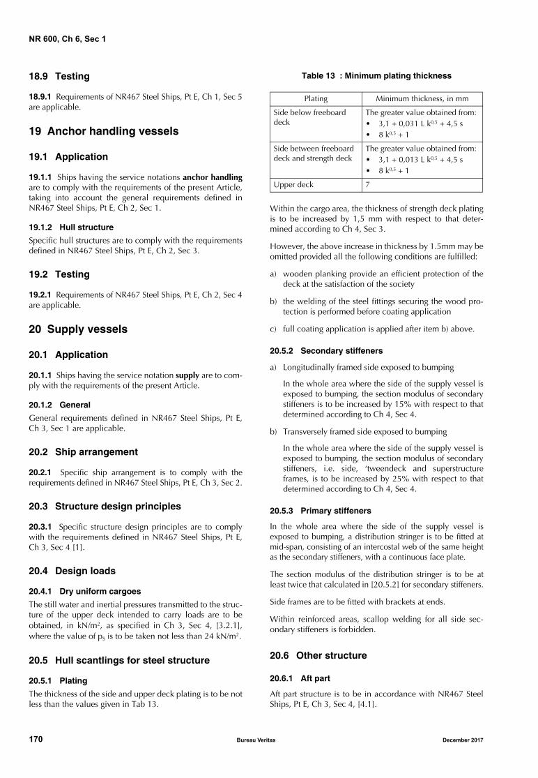
NR 600, Ch 6, Sec 1
18.9 Testing
18.9.1 Requirements of NR467 Steel Ships, Pt E, Ch 1, Sec 5are applicable.
19 Anchor handling vessels
19.1 Application
19.1.1 Ships having the service notations anchor handlingare to comply with the requirements of the present Article,taking into account the general requirements defined inNR467 Steel Ships, Pt E, Ch 2, Sec 1.
19.1.2 Hull structure
Specific hull structures are to comply with the requirementsdefined in NR467 Steel Ships, Pt E, Ch 2, Sec 3.
19.2 Testing
19.2.1 Requirements of NR467 Steel Ships, Pt E, Ch 2, Sec 4are applicable.
20 Supply vessels
20.1 Application
20.1.1 Ships having the service notation supply are to com-ply with the requirements of the present Article.
20.1.2 General
General requirements defined in NR467 Steel Ships, Pt E,Ch 3, Sec 1 are applicable.
20.2 Ship arrangement
20.2.1 Specific ship arrangement is to comply with therequirements defined in NR467 Steel Ships, Pt E, Ch 3, Sec 2.
20.3 Structure design principles
20.3.1 Specific structure design principles are to complywith the requirements defined in NR467 Steel Ships, Pt E,Ch 3, Sec 4 [1].
20.4 Design loads
20.4.1 Dry uniform cargoes
The still water and inertial pressures transmitted to the struc-ture of the upper deck intended to carry loads are to beobtained, in kN/m2, as specified in Ch 3, Sec 4, [3.2.1],where the value of pS is to be taken not less than 24 kN/m2.
20.5 Hull scantlings for steel structure
20.5.1 Plating
The thickness of the side and upper deck plating is to be notless than the values given in Tab 13.
Table 13 : Minimum plating thickness
Within the cargo area, the thickness of strength deck platingis to be increased by 1,5 mm with respect to that deter-mined according to Ch 4, Sec 3.
However, the above increase in thickness by 1.5mm may beomitted provided all the following conditions are fulfilled:
a) wooden planking provide an efficient protection of thedeck at the satisfaction of the society
b) the welding of the steel fittings securing the wood pro-tection is performed before coating application
c) full coating application is applied after item b) above.
20.5.2 Secondary stiffeners
a) Longitudinally framed side exposed to bumping
In the whole area where the side of the supply vessel isexposed to bumping, the section modulus of secondarystiffeners is to be increased by 15% with respect to thatdetermined according to Ch 4, Sec 4.
b) Transversely framed side exposed to bumping
In the whole area where the side of the supply vessel isexposed to bumping, the section modulus of secondarystiffeners, i.e. side, ‘tweendeck and superstructureframes, is to be increased by 25% with respect to thatdetermined according to Ch 4, Sec 4.
20.5.3 Primary stiffeners
In the whole area where the side of the supply vessel isexposed to bumping, a distribution stringer is to be fitted atmid-span, consisting of an intercostal web of the same heightas the secondary stiffeners, with a continuous face plate.
The section modulus of the distribution stringer is to be atleast twice that calculated in [20.5.2] for secondary stiffeners.
Side frames are to be fitted with brackets at ends.
Within reinforced areas, scallop welding for all side sec-ondary stiffeners is forbidden.
20.6 Other structure
20.6.1 Aft part
Aft part structure is to be in accordance with NR467 SteelShips, Pt E, Ch 3, Sec 4, [4.1].
Plating Minimum thickness, in mm
Side below freeboard deck
The greater value obtained from:• 3,1 + 0,031 L k0,5 + 4,5 s• 8 k0,5 + 1
Side between freeboard deck and strength deck
The greater value obtained from:• 3,1 + 0,013 L k0,5 + 4,5 s• 8 k0,5 + 1
Upper deck 7
170 Bureau Veritas December 2017
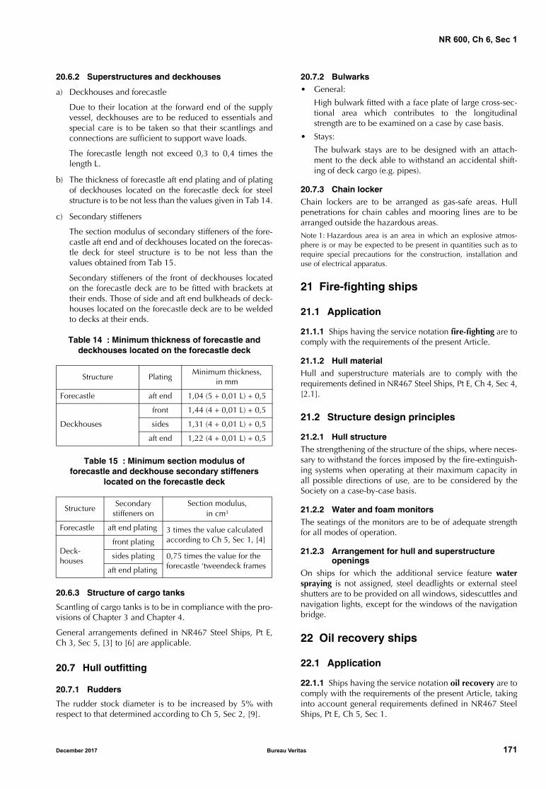
NR 600, Ch 6, Sec 1
20.6.2 Superstructures and deckhouses
a) Deckhouses and forecastle
Due to their location at the forward end of the supplyvessel, deckhouses are to be reduced to essentials andspecial care is to be taken so that their scantlings andconnections are sufficient to support wave loads.
The forecastle length not exceed 0,3 to 0,4 times thelength L.
b) The thickness of forecastle aft end plating and of platingof deckhouses located on the forecastle deck for steelstructure is to be not less than the values given in Tab 14.
c) Secondary stiffeners
The section modulus of secondary stiffeners of the fore-castle aft end and of deckhouses located on the forecas-tle deck for steel structure is to be not less than thevalues obtained from Tab 15.
Secondary stiffeners of the front of deckhouses locatedon the forecastle deck are to be fitted with brackets attheir ends. Those of side and aft end bulkheads of deck-houses located on the forecastle deck are to be weldedto decks at their ends.
Table 14 : Minimum thickness of forecastle and deckhouses located on the forecastle deck
Table 15 : Minimum section modulus offorecastle and deckhouse secondary stiffeners
located on the forecastle deck
20.6.3 Structure of cargo tanks
Scantling of cargo tanks is to be in compliance with the pro-visions of Chapter 3 and Chapter 4.
General arrangements defined in NR467 Steel Ships, Pt E,Ch 3, Sec 5, [3] to [6] are applicable.
20.7 Hull outfitting
20.7.1 Rudders
The rudder stock diameter is to be increased by 5% withrespect to that determined according to Ch 5, Sec 2, [9].
20.7.2 Bulwarks• General:
High bulwark fitted with a face plate of large cross-sec-tional area which contributes to the longitudinalstrength are to be examined on a case by case basis.
• Stays:
The bulwark stays are to be designed with an attach-ment to the deck able to withstand an accidental shift-ing of deck cargo (e.g. pipes).
20.7.3 Chain lockerChain lockers are to be arranged as gas-safe areas. Hullpenetrations for chain cables and mooring lines are to bearranged outside the hazardous areas.
Note 1: Hazardous area is an area in which an explosive atmos-phere is or may be expected to be present in quantities such as torequire special precautions for the construction, installation anduse of electrical apparatus.
21 Fire-fighting ships
21.1 Application
21.1.1 Ships having the service notation fire-fighting are tocomply with the requirements of the present Article.
21.1.2 Hull materialHull and superstructure materials are to comply with therequirements defined in NR467 Steel Ships, Pt E, Ch 4, Sec 4,[2.1].
21.2 Structure design principles
21.2.1 Hull structureThe strengthening of the structure of the ships, where neces-sary to withstand the forces imposed by the fire-extinguish-ing systems when operating at their maximum capacity inall possible directions of use, are to be considered by theSociety on a case-by-case basis.
21.2.2 Water and foam monitorsThe seatings of the monitors are to be of adequate strengthfor all modes of operation.
21.2.3 Arrangement for hull and superstructure openings
On ships for which the additional service feature waterspraying is not assigned, steel deadlights or external steelshutters are to be provided on all windows, sidescuttles andnavigation lights, except for the windows of the navigationbridge.
22 Oil recovery ships
22.1 Application
22.1.1 Ships having the service notation oil recovery are tocomply with the requirements of the present Article, takinginto account general requirements defined in NR467 SteelShips, Pt E, Ch 5, Sec 1.
Structure PlatingMinimum thickness,
in mm
Forecastle aft end 1,04 (5 + 0,01 L) + 0,5
Deckhouses
front 1,44 (4 + 0,01 L) + 0,5
sides 1,31 (4 + 0,01 L) + 0,5
aft end 1,22 (4 + 0,01 L) + 0,5
StructureSecondary
stiffeners onSection modulus,
in cm3
Forecastle aft end plating 3 times the value calculated according to Ch 5, Sec 1, [4]
Deck-houses
front plating
sides plating 0,75 times the value for the forecastle ‘tweendeck framesaft end plating
December 2017 Bureau Veritas 171
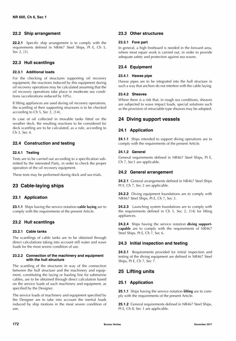
NR 600, Ch 6, Sec 1
22.2 Ship arrangement
22.2.1 Specific ship arrangement is to comply with therequirements defined in NR467 Steel Ships, Pt E, Ch 5,Sec 2, [1].
22.3 Hull scantlings
22.3.1 Additional loads
For the checking of structures supporting oil recoveryequipment, the reactions induced by this equipment duringoil recovery operations may be calculated assuming that theoil recovery operations take place in moderate sea condi-tions (accelerations reduced by 10%).
If lifting appliances are used during oil recovery operations,the scantling of their supporting structures is to be checkedaccording to Ch 5, Sec 2, [14].
In case of oil collected in movable tanks fitted on theweather deck, the resulting reactions to be considered fordeck scantling are to be calculated, as a rule, according toCh 3, Sec 4.
22.4 Construction and testing
22.4.1 Testing
Tests are to be carried out according to a specification sub-mitted by the interested Party, in order to check the properoperation of the oil recovery equipment.
These tests may be performed during dock and sea trials.
23 Cable-laying ships
23.1 Application
23.1.1 Ships having the service notation cable laying are tocomply with the requirements of the present Article.
23.2 Hull scantlings
23.2.1 Cable tanks
The scantlings of cable tanks are to be obtained throughdirect calculations taking into account still water and waveloads for the most severe condition of use.
23.2.2 Connection of the machinery and equipment with the hull structure
The scantling of the structures in way of the connectionbetween the hull structure and the machinery and equip-ment, constituting the laying or hauling line for submarinecables, are to be obtained through direct calculation basedon the service loads of such machinery and equipment, asspecified by the Designer.
The service loads of machinery and equipment specified bythe Designer are to take into account the inertial loadsinduced by ship motions in the most severe condition ofuse.
23.3 Other structures
23.3.1 Fore part
In general, a high freeboard is needed in the forward area,where most repair work is carried out, in order to provideadequate safety and protection against sea waves.
23.4 Equipment
23.4.1 Hawse pipe
Hawse pipes are to be integrated into the hull structure insuch a way that anchors do not interfere with the cable laying.
23.4.2 Sheaves
Where there is a risk that, in rough sea conditions, sheavesare subjected to wave impact loads, special solutions suchas the provision of retractable type sheaves may be adopted.
24 Diving support vessels
24.1 Application
24.1.1 Ships intended to support diving operations are tocomply with the requirements of the present Article.
24.1.2 General
General requirements defined in NR467 Steel Ships, Pt E,Ch 7, Sec1 are applicable.
24.2 General arrangement
24.2.1 General arrangements defined in NR467 Steel ShipsPt E, Ch 7, Sec 2 are applicable.
24.2.2 Diving equipment foundations are to comply withNR467 Steel Ships, Pt E, Ch 7, Sec 3.
24.2.3 Launching system foundations are to comply withthe requirements defined in Ch 5, Sec 2, [14] for liftingappliances.
24.2.4 Ships having the service notation diving support-capable are to comply with the requirements of NR467Steel Ships, Pt E, Ch 7, Sec 6.
24.3 Initial inspection and testing
24.3.1 Requirements provided for initial inspection andtesting of the diving equipment are defined in NR467 SteelShips, Pt E, Ch 7, Sec 7.
25 Lifting units
25.1 Application
25.1.1 Ships having the service notation lifting are to com-ply with the requirements of the present Article.
25.1.2 General requirements defined in NR467 Steel Ships,Pt E, Ch 8, Sec 1 are applicable.
172 Bureau Veritas December 2017
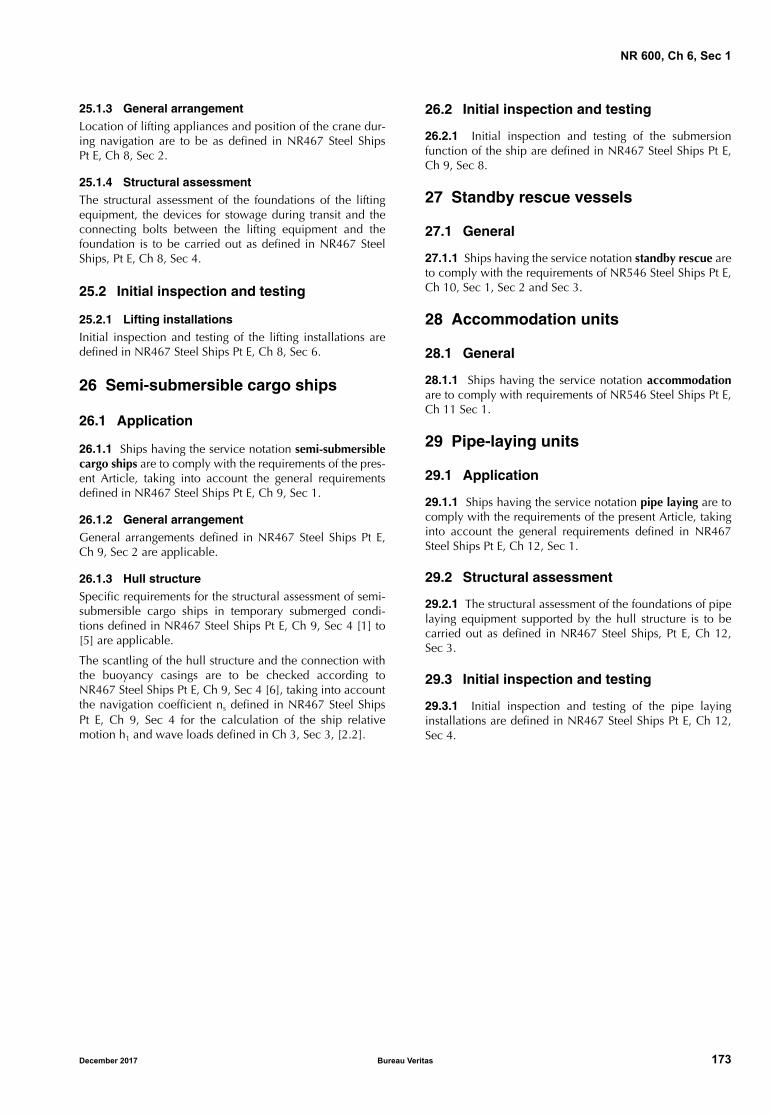
NR 600, Ch 6, Sec 1
25.1.3 General arrangementLocation of lifting appliances and position of the crane dur-ing navigation are to be as defined in NR467 Steel ShipsPt E, Ch 8, Sec 2.
25.1.4 Structural assessmentThe structural assessment of the foundations of the liftingequipment, the devices for stowage during transit and theconnecting bolts between the lifting equipment and thefoundation is to be carried out as defined in NR467 SteelShips, Pt E, Ch 8, Sec 4.
25.2 Initial inspection and testing
25.2.1 Lifting installationsInitial inspection and testing of the lifting installations aredefined in NR467 Steel Ships Pt E, Ch 8, Sec 6.
26 Semi-submersible cargo ships
26.1 Application
26.1.1 Ships having the service notation semi-submersiblecargo ships are to comply with the requirements of the pres-ent Article, taking into account the general requirementsdefined in NR467 Steel Ships Pt E, Ch 9, Sec 1.
26.1.2 General arrangementGeneral arrangements defined in NR467 Steel Ships Pt E,Ch 9, Sec 2 are applicable.
26.1.3 Hull structureSpecific requirements for the structural assessment of semi-submersible cargo ships in temporary submerged condi-tions defined in NR467 Steel Ships Pt E, Ch 9, Sec 4 [1] to[5] are applicable.
The scantling of the hull structure and the connection withthe buoyancy casings are to be checked according toNR467 Steel Ships Pt E, Ch 9, Sec 4 [6], taking into accountthe navigation coefficient ns defined in NR467 Steel ShipsPt E, Ch 9, Sec 4 for the calculation of the ship relativemotion h1 and wave loads defined in Ch 3, Sec 3, [2.2].
26.2 Initial inspection and testing
26.2.1 Initial inspection and testing of the submersionfunction of the ship are defined in NR467 Steel Ships Pt E,Ch 9, Sec 8.
27 Standby rescue vessels
27.1 General
27.1.1 Ships having the service notation standby rescue areto comply with the requirements of NR546 Steel Ships Pt E,Ch 10, Sec 1, Sec 2 and Sec 3.
28 Accommodation units
28.1 General
28.1.1 Ships having the service notation accommodationare to comply with requirements of NR546 Steel Ships Pt E,Ch 11 Sec 1.
29 Pipe-laying units
29.1 Application
29.1.1 Ships having the service notation pipe laying are tocomply with the requirements of the present Article, takinginto account the general requirements defined in NR467Steel Ships Pt E, Ch 12, Sec 1.
29.2 Structural assessment
29.2.1 The structural assessment of the foundations of pipelaying equipment supported by the hull structure is to becarried out as defined in NR467 Steel Ships, Pt E, Ch 12,Sec 3.
29.3 Initial inspection and testing
29.3.1 Initial inspection and testing of the pipe layinginstallations are defined in NR467 Steel Ships Pt E, Ch 12,Sec 4.
December 2017 Bureau Veritas 173

NR 600, Ch 6, Sec 1
174 Bureau Veritas December 2017

NR 600
Chapter 7
CONSTRUCTION AND TESTING
SECTION 1 GENERAL
SECTION 2 WELDING FOR STEEL
SECTION 3 TESTING
SECTION 4 CONSTRUCTION SURVEY
December 2017 Bureau Veritas 175

176 Bureau Veritas December 2017
NR 600, Ch 7, Sec 1
December 2017 Bureau Veritas 177
SECTION 1 GENERAL
1 General
1.1
1.1.1 The present Chapter contains the requirements con-cerning the welding, welds and assembling of structure, andthe testing and construction survey.
2 Welding, welds and assembly of structure
2.1 Material
2.1.1 The scantling and joint design of welded connectionfor ships built in steel materials are defined in Sec 2.
2.1.2 The equivalent requirements for ships built in alumin-ium alloys are defined in NR561 Aluminium Ships.
The conditions for heterogeneous assembly between steeland aluminium structures are also to be as defined inNR561 Aluminium Ships.
2.1.3 The scantling of joint assembly for ships built in com-posite materials are to be as defined in NR546 CompositeShips.
3 Testing
3.1 General
3.1.1 The testing conditions for tanks, watertight andweathertight structures for ships built in steel, aluminiumand composite materials are define in Sec 3.
4 Construction survey
4.1 General
4.1.1 The requirements for hull construction and surveywithin the scope of classification and/or certification ofships hulls are defined in: • for steel ship: in Sec 4• for aluminium ship: in the NR561 Aluminium Ships• for composite ship: in the NR546 Composite Ships.
NR 600, Ch 7, Sec 2
SECTION 2 WELDING FOR STEEL
1 General
1.1 Materials
1.1.1 The requirements of the present Section apply to thescantling and joint design of welded connection of shipsbuilt in steel materials.
1.2 Application
1.2.1 The scantling and preparation for the welding of steelhull structure are to be as defined in the present Section.
Other equivalent standards may be accepted by the Society,on a case-by-case basis.
The general requirements relevant to the execution of weld-ing, inspection and qualification of welding procedures aregiven in Chapter 5 of NR216 Materials and Welding.
1.2.2 Welding of various types of steel is to be carried outby means of welding procedures approved for the purpose.
1.2.3 Weld connections are to be executed according to:
• the approved hull construction plans, and
• the weld and welding booklets submitted to the Society.
Any details not specifically represented in the plans are, inany case, to comply with the applicable requirements of theSociety.
1.2.4 The method used to prepare the parts to be welded isleft to the discretion of each shipbuilder, according to itsown technology and experience.
These methods are to be reviewed during the qualificationof welding procedure, as defined in [1.3.2].
1.3 Weld and welding booklet
1.3.1 Weld booklet
A weld booklet, including the weld scantling such as throatthickness, pitch and design of joint, is to be submitted to theSociety for examination.
The weld booklet is not required if the structure drawingssubmitted to the Society contain the necessary relevant datadefining the weld scantling.
1.3.2 Welding booklet
A welding booklet including the welding procedures, oper-ations, inspections and the modifications and repair duringconstruction as defined in Sec 4, [3.4] is to be submitted tothe Surveyor for examination.
2 Scantling of welds
2.1 Butt welds
2.1.1 As a rule, all structural butt joints are to be full pene-tration welds completed by a backing run weld.
2.2 Butt welds on permanent backing
2.2.1 Butt welding on permanent backing may be acceptedwhere a backing run is not feasible.
In this case, the type of bevel and the gap between themembers to be assembled are to be such as to ensure aproper penetration of the weld on its backing.
2.3 Fillet weld on a lap-joint
2.3.1 General
Fillet weld in a lap joint may be used only for members sub-mitted to moderate stresses, taking into account the typicaldetails shown on Tab 1.
Continuous welding is generally to be adopted.
2.3.2 The surfaces of lap-joints are to be in sufficientlyclose contact.
2.4 Slot welds
2.4.1 Slot welding may be used where fillet welding is notpossible.
Slot welding is, in general, permitted only where stresses actin a predominant direction. Slot welds are, as far as possi-ble, to be aligned in this direction.
2.4.2 Slot welds are to be of appropriate shape (in generaloval) and dimensions, depending on the plate thickness,and may not be completely filled by the weld (see Tab 2).
The distance between two consecutive slot welds is to benot greater than a value which is defined on a case-by-casebasis taking into account:
• the transverse spacing between adjacent slot weld lines
• the stresses acting in the connected plates
• the structural arrangement below the connected plates.
2.5 Plug welding
2.5.1 Plug welding may be adopted exceptionally as a sub-stitute to slot welding.
Typical details are given in Tab 2.
178 Bureau Veritas December 2017
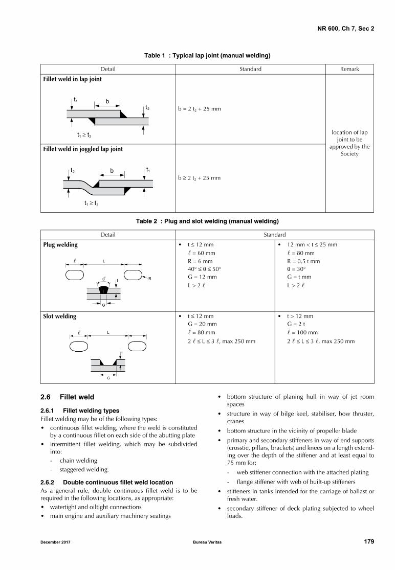
NR 600, Ch 7, Sec 2
Table 1 : Typical lap joint (manual welding)
Table 2 : Plug and slot welding (manual welding)
2.6 Fillet weld
2.6.1 Fillet welding typesFillet welding may be of the following types:• continuous fillet welding, where the weld is constituted
by a continuous fillet on each side of the abutting plate• intermittent fillet welding, which may be subdivided
into:- chain welding- staggered welding.
2.6.2 Double continuous fillet weld locationAs a general rule, double continuous fillet weld is to berequired in the following locations, as appropriate:• watertight and oiltight connections• main engine and auxiliary machinery seatings
• bottom structure of planing hull in way of jet roomspaces
• structure in way of bilge keel, stabiliser, bow thruster,cranes
• bottom structure in the vicinity of propeller blade
• primary and secondary stiffeners in way of end supports(crosstie, pillars, brackets) and knees on a length extend-ing over the depth of the stiffener and at least equal to75 mm for:
- web stiffener connection with the attached plating
- flange stiffener with web of built-up stiffeners
• stiffeners in tanks intended for the carriage of ballast orfresh water.
• secondary stiffener of deck plating subjected to wheelloads.
Detail Standard Remark
Fillet weld in lap joint
b = 2 t2 + 25 mm
location of lap joint to be
approved by the Society
Fillet weld in joggled lap joint
b ≥ 2 t2 + 25 mm
Detail Standard
Plug welding • t ≤ 12 mm = 60 mmR = 6 mm40° ≤ θ ≤ 50°G = 12 mmL > 2
• 12 mm < t ≤ 25 mm = 80 mmR = 0,5 t mmθ = 30°G = t mmL > 2
Slot welding • t ≤ 12 mmG = 20 mm = 80 mm
2 ≤ L ≤ 3 , max 250 mm
• t > 12 mmG = 2 t = 100 mm
2 ≤ L ≤ 3 , max 250 mm
�� �
��
� � �� �
�����
� � �� �
�
�
��
��
�
�
�
��
December 2017 Bureau Veritas 179
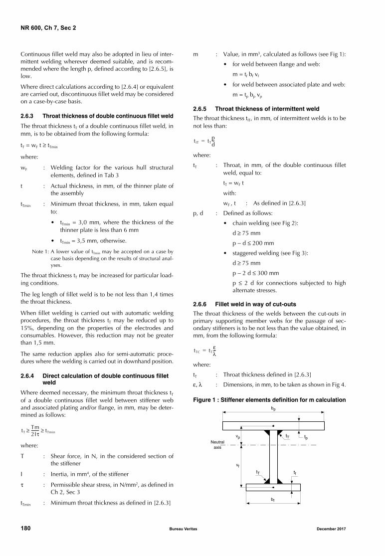
NR 600, Ch 7, Sec 2
Continuous fillet weld may also be adopted in lieu of inter-mittent welding wherever deemed suitable, and is recom-mended where the length p, defined according to [2.6.5], islow.
Where direct calculations according to [2.6.4] or equivalentare carried out, discontinuous fillet weld may be consideredon a case-by-case basis.
2.6.3 Throat thickness of double continuous fillet weld
The throat thickness tT of a double continuous fillet weld, inmm, is to be obtained from the following formula:
tT = wF t ≥ tTmin
where:
wF : Welding factor for the various hull structuralelements, defined in Tab 3
t : Actual thickness, in mm, of the thinner plate ofthe assembly
tTmin : Minimum throat thickness, in mm, taken equalto:
• tTmin = 3,0 mm, where the thickness of thethinner plate is less than 6 mm
• tTmin = 3,5 mm, otherwise.
Note 1: A lower value of tTmin may be accepted on a case bycase basis depending on the results of structural anal-yses.
The throat thickness tT may be increased for particular load-ing conditions.
The leg length of fillet weld is to be not less than 1,4 timesthe throat thickness.
When fillet welding is carried out with automatic weldingprocedures, the throat thickness tT may be reduced up to15%, depending on the properties of the electrodes andconsumables. However, this reduction may not be greaterthan 1,5 mm.
The same reduction applies also for semi-automatic proce-dures where the welding is carried out in downhand position.
2.6.4 Direct calculation of double continuous fillet weld
Where deemed necessary, the minimum throat thickness tTof a double continuous fillet weld between stiffener weband associated plating and/or flange, in mm, may be deter-mined as follows:
where:
T : Shear force, in N, in the considered section ofthe stiffener
I : Inertia, in mm4, of the stiffener
τ : Permissible shear stress, in N/mm2, as defined inCh 2, Sec 3
tTmin : Minimum throat thickness as defined in [2.6.3]
m : Value, in mm3, calculated as follows (see Fig 1):
• for weld between flange and web:
m = tf bf vf
• for weld between associated plate and web:
m = tp bp vp
2.6.5 Throat thickness of intermittent weld
The throat thickness tIT, in mm, of intermittent welds is to benot less than:
where:
tT : Throat, in mm, of the double continuous filletweld, equal to:
tT = wF t
with:
wF , t : As defined in [2.6.3]
p, d : Defined as follows:
• chain welding (see Fig 2):
d ≥ 75 mm
p − d ≤ 200 mm
• staggered welding (see Fig 3):
d ≥ 75 mm
p − 2 d ≤ 300 mm
p ≤ 2 d for connections subjected to highalternate stresses.
2.6.6 Fillet weld in way of cut-outs
The throat thickness of the welds between the cut-outs inprimary supporting member webs for the passage of sec-ondary stiffeners is to be not less than the value obtained, inmm, from the following formula:
where:
tT : Throat thickness defined in [2.6.3]
ε, λ : Dimensions, in mm, to be taken as shown in Fig 4.
Figure 1 : Stiffener elements definition for m calculation
tTTm2Iτ-------- tTmin≥ ≥
tIT tTpd---=
tTC tTελ---=
tp
tf
bf
vf
Neutralaxis
vp
tT
tT
bp
180 Bureau Veritas December 2017
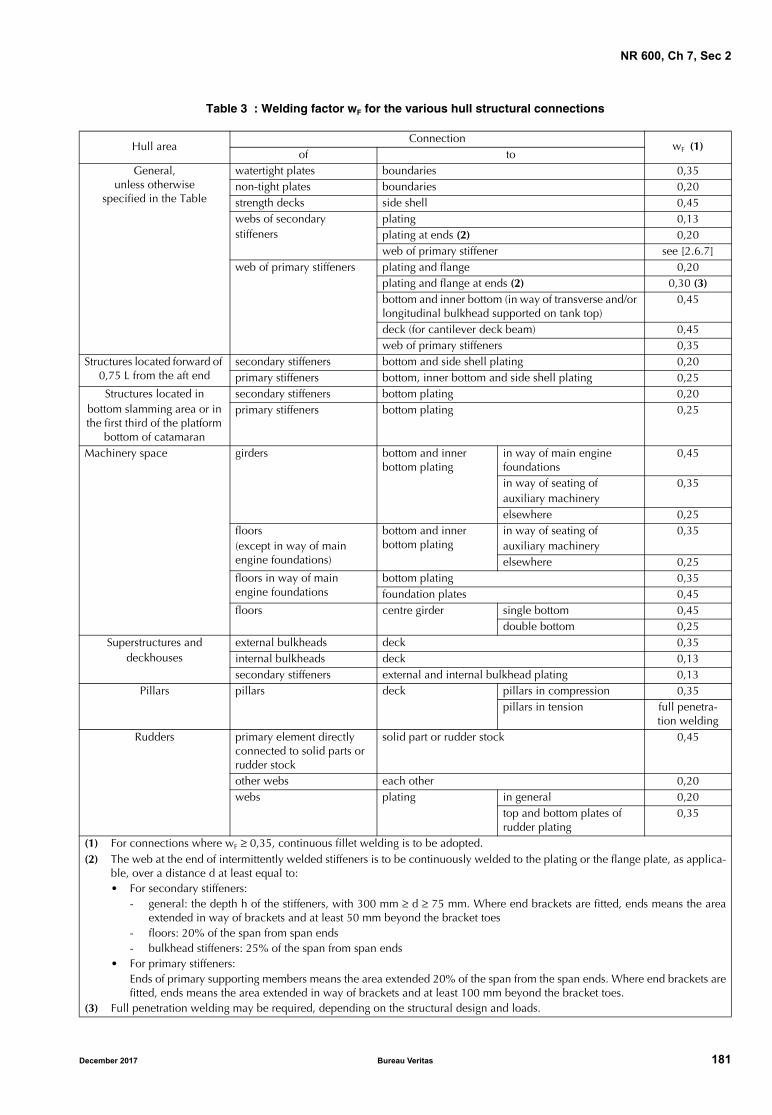
NR 600, Ch 7, Sec 2
Table 3 : Welding factor wF for the various hull structural connections
Hull areaConnection
wF (1)of to
General, unless otherwise
specified in the Table
watertight plates boundaries 0,35non-tight plates boundaries 0,20strength decks side shell 0,45webs of secondary stiffeners
plating 0,13plating at ends (2) 0,20web of primary stiffener see [2.6.7]
web of primary stiffeners plating and flange 0,20plating and flange at ends (2) 0,30 (3)bottom and inner bottom (in way of transverse and/or longitudinal bulkhead supported on tank top)
0,45
deck (for cantilever deck beam) 0,45web of primary stiffeners 0,35
Structures located forward of 0,75 L from the aft end
secondary stiffeners bottom and side shell plating 0,20primary stiffeners bottom, inner bottom and side shell plating 0,25
Structures located in bottom slamming area or in the first third of the platform
bottom of catamaran
secondary stiffeners bottom plating 0,20primary stiffeners bottom plating 0,25
Machinery space girders bottom and inner bottom plating
in way of main engine foundations
0,45
in way of seating of auxiliary machinery
0,35
elsewhere 0,25floors (except in way of main engine foundations)
bottom and inner bottom plating
in way of seating of auxiliary machinery
0,35
elsewhere 0,25floors in way of main engine foundations
bottom plating 0,35foundation plates 0,45
floors centre girder single bottom 0,45double bottom 0,25
Superstructures and deckhouses
external bulkheads deck 0,35internal bulkheads deck 0,13secondary stiffeners external and internal bulkhead plating 0,13
Pillars pillars deck pillars in compression 0,35pillars in tension full penetra-
tion weldingRudders primary element directly
connected to solid parts or rudder stock
solid part or rudder stock 0,45
other webs each other 0,20webs plating in general 0,20
top and bottom plates of rudder plating
0,35
(1) For connections where wF ≥ 0,35, continuous fillet welding is to be adopted.(2) The web at the end of intermittently welded stiffeners is to be continuously welded to the plating or the flange plate, as applica-
ble, over a distance d at least equal to: • For secondary stiffeners:
- general: the depth h of the stiffeners, with 300 mm ≥ d ≥ 75 mm. Where end brackets are fitted, ends means the areaextended in way of brackets and at least 50 mm beyond the bracket toes
- floors: 20% of the span from span ends- bulkhead stiffeners: 25% of the span from span ends
• For primary stiffeners:Ends of primary supporting members means the area extended 20% of the span from the span ends. Where end brackets arefitted, ends means the area extended in way of brackets and at least 100 mm beyond the bracket toes.
(3) Full penetration welding may be required, depending on the structural design and loads.
December 2017 Bureau Veritas 181

NR 600, Ch 7, Sec 2
Figure 2 : Intermittent chain welding
Figure 3 : Intermittent staggered welding
Figure 4 : Continuous fillet welding between cut-outs
2.6.7 Welding between secondary and primary stiffeners
As a general rule, the resistant weld section AW, in cm2, ofthe fillet weld connecting the secondary stiffeners to theweb of primary members is not to be less than:
a) General case:
where:
ϕ : Coefficient as indicated in Tab 4
p : Design pressure, in kN/m2, acting on thesecondary stiffeners
s : Spacing of secondary stiffeners, in m
: Span of secondary stiffeners, in m
k : Greatest material factor of secondary stiff-ener and primary member, as defined in Ch1, Sec 2
b) Case of side shell impact:
where:
s : Spacing of secondary stiffeners, in m, with-out being taken greater than 0,6 m
P : Pressure, in KN/m2, to be taken equal to:
P = Cp Pssmin
Cp : Pressure coefficient equal to:
Cp = -0,98s2 + 0,3s + 0,95 ≥ 0,8
pssmin : Impact pressure, in kN/m2, acting on thesecondary stiffeners as defined in Ch 3, Sec3, [3.1.2].
Table 4 : Coefficient ϕ
3 Typical joint preparation
3.1 General
3.1.1 The type of connection and the edge preparation areto be appropriate to the welding procedure adopted, thestructural elements to be connected and the stresses towhich they are subjected.
3.2 Butt welding
3.2.1 Permissible root gap between elements to be weldedand edge preparations are to be defined during qualificationtests of welding procedures and indicated in the weldingbooklet.
For guidance purposes, typical edge preparations and gapsare indicated in Tab 5.
3.2.2 In case of welding of two plates of different thicknessequal to or greater than:
• 3 mm, if the thinner plate has a thickness equal to orless than 10 mm, or
• 4 mm, if the thinner plate has a thickness greater than10 mm,
a taper having a length of not less than 4 times the differencein thickness is to be adopted for connections of plating per-pendicular to the direction of main stresses. For connectionsof plating parallel to the direction of main stresses, the taperlength may be reduced to 3 times the difference in thickness.
When the difference in thickness is less than the above val-ues, it may be accommodated in the weld transitionbetween plates.
For large thicknesses (e.g. 25 mm), other criteria may be con-sidered on a case-by-case basis, when deemed equivalent.
3.2.3 Butt welding on backing
For butt welding on temporary or permanent backing, theedge preparations and gaps are to be defined by the ship-yard, taking into account the type of backing plate.
Throat a
ε
λ
AW ϕps 1 s2------–
k10 3–=
AW ϕsP 0 6, s4---–
k10 3–=
Case Weld ϕ
1Parallel to the reaction exerted on primarymember
100
2Perpendicular to the reaction exerted on pri-mary member
75
182 Bureau Veritas December 2017
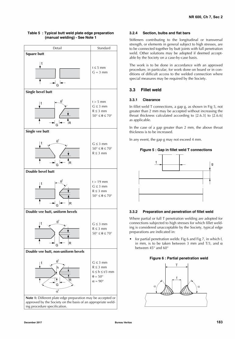
NR 600, Ch 7, Sec 2
Table 5 : Typical butt weld plate edge preparation(manual welding) - See Note 1
3.2.4 Section, bulbs and flat bars
Stiffeners contributing to the longitudinal or transversalstrength, or elements in general subject to high stresses, areto be connected together by butt joints with full penetrationweld. Other solutions may be adopted if deemed accept-able by the Society on a case-by-case basis.
The work is to be done in accordance with an approvedprocedure, in particular, for work done on board or in con-ditions of difficult access to the welded connection wherespecial measures may be required by the Society.
3.3 Fillet weld
3.3.1 Clearance
In fillet weld T connections, a gap g, as shown in Fig 5, notgreater than 2 mm may be accepted without increasing thethroat thickness calculated according to [2.6.3] to [2.6.6]as applicable.
In the case of a gap greater than 2 mm, the above throatthickness is to be increased.
In any event, the gap g may not exceed 4 mm.
Figure 5 : Gap in fillet weld T connections
3.3.2 Preparation and penetration of fillet weld
Where partial or full T penetration welding are adopted forconnections subjected to high stresses for which fillet weld-ing is considered unacceptable by the Society, typical edgepreparations are indicated in:
• for partial penetration welds: Fig 6 and Fig 7, in which f,in mm, is to be taken between 3 mm and T/3, and αbetween 45° and 60°
Figure 6 : Partial penetration weld
Detail Standard
Square butt
t ≤ 5 mmG = 3 mm
Single bevel butt
t > 5 mmG ≤ 3 mmR ≤ 3 mm50° ≤ θ ≤ 70°
Single vee butt
G ≤ 3 mm50° ≤ θ ≤ 70°R ≤ 3 mm
Double bevel butt
t > 19 mmG ≤ 3 mmR ≤ 3 mm50° ≤ θ ≤ 70°
Double vee butt, uniform bevels
G ≤ 3 mmR ≤ 3 mm50° ≤ θ ≤ 70°
Double vee butt, non-uniform bevels
G ≤ 3 mmR ≤ 3 mm6 ≤ h ≤ t/3 mmθ = 50°α = 90°
Note 1: Different plate edge preparation may be accepted orapproved by the Society on the basis of an appropriate weld-ing procedure specification.
�
�
�
�
��
�
�
��
��
�
�
��
�
�
�
��
�
�
�
��
�
��
�
t g
T
f
� �
December 2017 Bureau Veritas 183
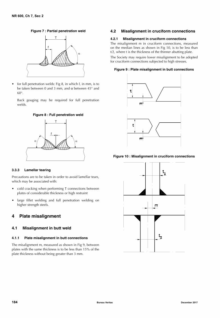
NR 600, Ch 7, Sec 2
Figure 7 : Partial penetration weld
• for full penetration welds: Fig 8, in which f, in mm, is tobe taken between 0 and 3 mm, and α between 45° and60°.
Back gouging may be required for full penetrationwelds.
Figure 8 : Full penetration weld
3.3.3 Lamellar tearing
Precautions are to be taken in order to avoid lamellar tears,which may be associated with:
• cold cracking when performing T connections betweenplates of considerable thickness or high restraint
• large fillet welding and full penetration welding onhigher strength steels.
4 Plate misalignment
4.1 Misalignment in butt weld
4.1.1 Plate misalignment in butt connections
The misalignment m, measured as shown in Fig 9, betweenplates with the same thickness is to be less than 15% of theplate thickness without being greater than 3 mm.
4.2 Misalignment in cruciform connections
4.2.1 Misalignment in cruciform connectionsThe misalignment m in cruciform connections, measuredon the median lines as shown in Fig 10, is to be less thant/2, where t is the thickness of the thinner abutting plate.
The Society may require lower misalignment to be adoptedfor cruciform connections subjected to high stresses.
Figure 9 : Plate misalignment in butt connections
Figure 10 : Misalignment in cruciform connections
�
�
�
�
�
��
184 Bureau Veritas December 2017
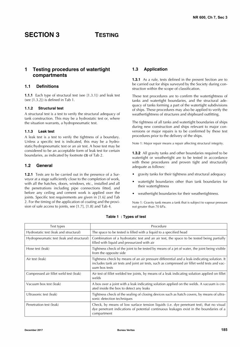
NR 600, Ch 7, Sec 3
SECTION 3 TESTING
1 Testing procedures of watertight compartments
1.1 Definitions
1.1.1 Each type of structural test (see [1.3.1]) and leak test(see [1.3.2]) is defined in Tab 1.
1.1.2 Structural test
A structural test is a test to verify the structural adequacy oftank construction. This may be a hydrostatic test or, wherethe situation warrants, a hydropneumatic test.
1.1.3 Leak test
A leak test is a test to verify the tightness of a boundary.Unless a specific test is indicated, this may be a hydro-static/hydropneumatic test or an air test. A hose test may beconsidered to be an acceptable form of leak test for certainboundaries, as indicated by footnote (3) of Tab 2.
1.2 General
1.2.1 Tests are to be carried out in the presence of a Sur-veyor at a stage sufficiently close to the completion of work,with all the hatches, doors, windows, etc., installed and allthe penetrations including pipe connections fitted, andbefore any ceiling and cement work is applied over thejoints. Specific test requirements are given in [1.6] and Tab2. For the timing of the application of coating and the provi-sion of safe access to joints, see [1.7], [1.8] and Tab 4.
1.3 Application
1.3.1 As a rule, tests defined in the present Section are tobe carried out for ships surveyed by the Society during con-struction within the scope of classification.
These test procedures are to confirm the watertightness oftanks and watertight boundaries, and the structural ade-quacy of tanks forming a part of the watertight subdivisionsof ships. These procedures may also be applied to verify theweathertightness of structures and shipboard outfitting.
The tightness of all tanks and watertight boundaries of shipsduring new construction and ships relevant to major con-versions or major repairs is to be confirmed by these testprocedures prior to the delivery of the ships.
Note 1: Major repair means a repair affecting structural integrity.
1.3.2 All gravity tanks and other boundaries required to bewatertight or weathertight are to be tested in accordancewith these procedures and proven tight and structurallyadequate as follows:
• gravity tanks for their tightness and structural adequacy
• watertight boundaries other than tank boundaries fortheir watertightness
• weathertight boundaries for their weathertightness.
Note 1: Gravity tank means a tank that is subject to vapour pressurenot greater than 70 kPa.
Table 1 : Types of test
Test types Procedure
Hydrostatic test (leak and structural) The space to be tested is filled with a liquid to a specified head
Hydropneumatic test (leak and structural) Combination of a hydrostatic test and an air test, the space to be tested being partiallyfilled with liquid and pressurized with air
Hose test (leak) Tightness check of the joint to be tested by means of a jet of water, the joint being visiblefrom the opposite side
Air test (leak) Tightness check by means of an air pressure differential and a leak-indicating solution. Itincludes tank air tests and joint air tests, such as compressed air fillet weld tests and vac-uum box tests
Compressed air fillet weld test (leak) Air test of fillet welded tee joints, by means of a leak indicating solution applied on filletwelds
Vacuum box test (leak) A box over a joint with a leak indicating solution applied on the welds. A vacuum is cre-ated inside the box to detect any leaks
Ultrasonic test (leak) Tightness check of the sealing of closing devices such as hatch covers, by means of ultra-sonic detection techniques
Penetration test (leak) Check, by means of low surface tension liquids (i.e. dye penetrant test), that no visualdye penetrant indications of potential continuous leakages exist in the boundaries of acompartment
December 2017 Bureau Veritas 185
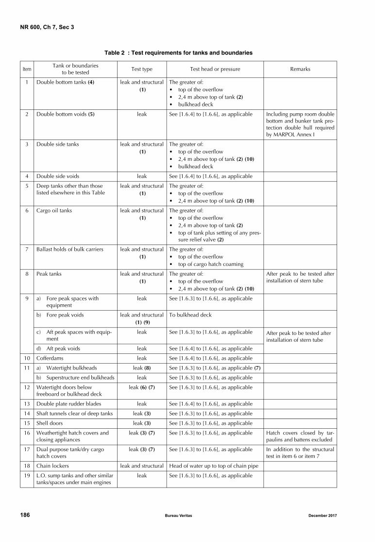
NR 600, Ch 7, Sec 3
Table 2 : Test requirements for tanks and boundaries
ItemTank or boundaries
to be testedTest type Test head or pressure Remarks
1 Double bottom tanks (4) leak and structural (1)
The greater of:• top of the overflow• 2,4 m above top of tank (2)• bulkhead deck
2 Double bottom voids (5) leak See [1.6.4] to [1.6.6], as applicable Including pump room doublebottom and bunker tank pro-tection double hull requiredby MARPOL Annex I
3 Double side tanks leak and structural (1)
The greater of:• top of the overflow• 2,4 m above top of tank (2) (10)• bulkhead deck
4 Double side voids leak See [1.6.4] to [1.6.6], as applicable
5 Deep tanks other than those listed elsewhere in this Table
leak and structural (1)
The greater of:• top of the overflow• 2,4 m above top of tank (2) (10)
6 Cargo oil tanks leak and structural (1)
The greater of:• top of the overflow• 2,4 m above top of tank (2)• top of tank plus setting of any pres-
sure relief valve (2)
7 Ballast holds of bulk carriers leak and structural (1)
The greater of:• top of the overflow• top of cargo hatch coaming
8 Peak tanks leak and structural (1)
The greater of:• top of the overflow• 2,4 m above top of tank (2) (10)
After peak to be tested afterinstallation of stern tube
9 a) Fore peak spaces with equipment
leak See [1.6.3] to [1.6.6], as applicable
b) Fore peak voids leak and structural (1) (9)
To bulkhead deck
c) Aft peak spaces with equip-ment
leak See [1.6.3] to [1.6.6], as applicable After peak to be tested after installation of stern tube
d) Aft peak voids leak See [1.6.4] to [1.6.6], as applicable
10 Cofferdams leak See [1.6.4] to [1.6.6], as applicable
11 a) Watertight bulkheads leak (8) See [1.6.3] to [1.6.6], as applicable (7)
b) Superstructure end bulkheads leak See [1.6.3] to [1.6.6], as applicable
12 Watertight doors below freeboard or bulkhead deck
leak (6) (7) See [1.6.3] to [1.6.6], as applicable
13 Double plate rudder blades leak See [1.6.4] to [1.6.6], as applicable
14 Shaft tunnels clear of deep tanks leak (3) See [1.6.3] to [1.6.6], as applicable
15 Shell doors leak (3) See [1.6.3] to [1.6.6], as applicable
16 Weathertight hatch covers and closing appliances
leak (3) (7) See [1.6.3] to [1.6.6], as applicable Hatch covers closed by tar-paulins and battens excluded
17 Dual purpose tank/dry cargo hatch covers
leak (3) (7) See [1.6.3] to [1.6.6], as applicable In addition to the structuraltest in item 6 or item 7
18 Chain lockers leak and structural Head of water up to top of chain pipe
19 L.O. sump tanks and other similar tanks/spaces under main engines
leak See [1.6.3] to [1.6.6], as applicable
186 Bureau Veritas December 2017
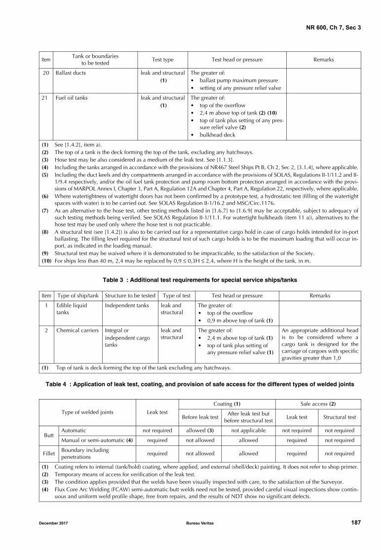
NR 600, Ch 7, Sec 3
Table 3 : Additional test requirements for special service ships/tanks
Table 4 : Application of leak test, coating, and provision of safe access for the different types of welded joints
20 Ballast ducts leak and structural (1)
The greater of:• ballast pump maximum pressure• setting of any pressure relief valve
21 Fuel oil tanks leak and structural (1)
The greater of:• top of the overflow• 2,4 m above top of tank (2) (10)• top of tank plus setting of any pres-
sure relief valve (2)• bulkhead deck
(1) See [1.4.2], item a).(2) The top of a tank is the deck forming the top of the tank, excluding any hatchways.(3) Hose test may be also considered as a medium of the leak test. See [1.1.3].(4) Including the tanks arranged in accordance with the provisions of NR467 Steel Ships Pt B, Ch 2, Sec 2, [3.1.4], where applicable.(5) Including the duct keels and dry compartments arranged in accordance with the provisions of SOLAS, Regulations II-1/11.2 and II-
1/9.4 respectively, and/or the oil fuel tank protection and pump room bottom protection arranged in accordance with the provi-sions of MARPOL Annex I, Chapter 3, Part A, Regulation 12A and Chapter 4, Part A, Regulation 22, respectively, where applicable.
(6) Where watertightness of watertight doors has not been confirmed by a prototype test, a hydrostatic test (filling of the watertightspaces with water) is to be carried out. See SOLAS Regulation II-1/16.2 and MSC/Circ.1176.
(7) As an alternative to the hose test, other testing methods listed in [1.6.7] to [1.6.9] may be acceptable, subject to adequacy ofsuch testing methods being verified. See SOLAS Regulation II-1/11.1. For watertight bulkheads (item 11 a)), alternatives to thehose test may be used only where the hose test is not practicable.
(8) A structural test (see [1.4.2]) is also to be carried out for a representative cargo hold in case of cargo holds intended for in-portballasting. The filling level required for the structural test of such cargo holds is to be the maximum loading that will occur in-port, as indicated in the loading manual.
(9) Structural test may be waived where it is demonstrated to be impracticable, to the satisfaction of the Society.(10) For ships less than 40 m, 2,4 may be replaced by 0,9 ≤ 0,3H ≤ 2,4, where H is the height of the tank, in m.
Item Type of ship/tank Structure to be tested Type of test Test head or pressure Remarks
1 Edible liquid tanks
Independent tanks leak and structural
The greater of:• top of the overflow• 0,9 m above top of tank (1)
2 Chemical carriers Integral or independent cargo tanks
leak and structural
The greater of:• 2,4 m above top of tank (1)• top of tank plus setting of
any pressure relief valve (1)
An appropriate additional headis to be considered where acargo tank is designed for thecarriage of cargoes with specificgravities greater than 1,0
(1) Top of tank is deck forming the top of the tank excluding any hatchways.
Type of welded joints Leak test
Coating (1) Safe access (2)
Before leak testAfter leak test but
before structural testLeak test Structural test
ButtAutomatic not required allowed (3) not applicable not required not required
Manual or semi-automatic (4) required not allowed allowed required not required
FilletBoundary including penetrations
required not allowed allowed required not required
(1) Coating refers to internal (tank/hold) coating, where applied, and external (shell/deck) painting. It does not refer to shop primer.(2) Temporary means of access for verification of the leak test.(3) The condition applies provided that the welds have been visually inspected with care, to the satisfaction of the Surveyor.(4) Flux Core Arc Welding (FCAW) semi-automatic butt welds need not be tested, provided careful visual inspections show contin-
uous and uniform weld profile shape, free from repairs, and the results of NDT show no significant defects.
ItemTank or boundaries
to be testedTest type Test head or pressure Remarks
December 2017 Bureau Veritas 187
NR 600, Ch 7, Sec 3
1.3.3 Testing of structures not listed in Tab 2 or Tab 3 is tobe specially considered by the Society.
1.3.4 Testing procedures of watertight compartments aredefined in:
• for SOLAS ships: [1.3.5]
• for non-SOLAS ships: [1.3.6].
1.3.5 Testing procedures of watertight compartments forSOLAS Ships are to be carried out in accordance with therequirements of [1.4] to [1.9], unless:
a) the shipyard provides documentary evidence of theshipowner’s agreement to a request to the Flag Adminis-tration for an exemption from the application of SOLASChapter II-1, Regulation 11, or for an equivalencyagreeing that the content of [1.10] is equivalent toSOLAS Chapter II-1, Regulation 11; and
b) the above-mentioned exemption/equivalency has beengranted by the responsible Flag Administration.
1.3.6 Testing procedures of watertight compartments fornon-SOLAS Ships are to be carried out in accordance withthe requirements of [1.4.1] and [1.5] to [1.9] in associationwith the alternative procedures to [1.4.2] defined in [1.10]and alternative test requirements for Tab 2.
1.4 Structural test procedures
1.4.1 Type and time of test
Where a structural test is specified in Tab 1 or Tab 2, ahydrostatic test in accordance with [1.6.1] is acceptable.Where practical limitations (strength of building berth, lightdensity of liquid, etc.) prevent the performance of a hydro-static test, a hydropneumatic test in accordance with [1.6.2]may be accepted instead.
A hydrostatic or hydropneumatic test for the confirmation ofstructural adequacy may be carried out while the ship isafloat, provided the results of a leak test are confirmed to besatisfactory before the ship is set afloat.
1.4.2 Testing schedule for new construction and major structural conversion or repair
a) Tanks which are intended to hold liquids, and whichform part of the watertight subdivision of the ship, shallbe tested for tightness and structural strength as indi-cated in Tab 2 and Tab 3.
b) The tank boundaries are to be tested from at least oneside. The tanks for the structural test are to be selectedso that all the representative structural members aretested for the expected tension and compression.
c) The watertight boundaries of spaces other than tanksmay be exempted from the structural test, provided thatthe boundary watertightness of the exempted spaces isverified by leak tests and inspections. The tank structuraltest is to be carried out and the requirements from itema) to item b) are to be applied for ballast holds, chainlockers, and for a representative cargo hold in case ofcargo holds intended for in-port ballasting.
d) Tanks which do not form part of the watertight subdivi-sion of the ship, may be exempted from structural testingprovided that the boundary watertightness of theexempted spaces is verified by leak tests and inspections.
1.5 Leak test procedures
1.5.1 For the leak tests specified in Tab 2, tank air tests,compressed air fillet weld tests and vacuum box tests, inaccordance respectively with [1.6.3], [1.6.5] and [1.6.6], ortheir combinations, are acceptable. Hydrostatic or hydro-pneumatic tests may be also accepted as leak tests, pro-vided [1.7], [1.8] and [1.9] are complied with. Hose tests,in accordance with [1.6.3], are also acceptable for items 14to 17 referred to in Tab 2, taking footnote (3) into account.
1.5.2 Air tests of joints may be carried out at the blockstage, provided that all work on the block that may affectthe tightness of a joint is completed before the test. See also[1.7.1] for the application of final coatings, [1.8] for the safeaccess to joints, and Tab 4 for the summary.
1.6 Test methods
1.6.1 Hydrostatic test
Unless another liquid is approved, hydrostatic tests are toconsist in filling the space with fresh water or sea water,whichever is appropriate for testing, to the level specified inTab 2 or Tab 3.
In case where a tank is intended for cargoes having a den-sity higher than the density of the liquid used for the test,the testing pressure height is to be specially considered.
All the external surfaces of the tested space are to be exam-ined for structural distortion, bulging and buckling, anyother related damage, and leaks.
1.6.2 Hydropneumatic test
Hydropneumatic tests, where approved, are to be such thatthe test condition, in conjunction with the approved liquidlevel and supplemental air pressure, simulates the actualloading as far as practicable. The requirements and recom-mendations in [1.6.4] for tank air tests apply also to hydro-pneumatic tests.
All the external surfaces of the tested space are to be exam-ined for structural distortion, bulging and buckling, anyother related damage, and leaks.
1.6.3 Hose test
Hose tests are to be carried out with the pressure in the hosenozzle maintained at least at 2·105 Pa during the test. Thenozzle is to have a minimum inside diameter of 12 mm andto be at a perpendicular distance from the joint not exceed-ing 1,5 m. The water jet is to impinge upon the weld.
Where a hose test is not practical because of possible dam-age to machinery, electrical equipment insulation, or outfit-ting items, it may be replaced by a careful visualexamination of the welded connections, supported wherenecessary by means such as a dye penetrant test or an ultra-sonic leak test, or equivalent.
188 Bureau Veritas December 2017
NR 600, Ch 7, Sec 3
1.6.4 Tank air test
All boundary welds, erection joints and penetrationsincluding pipe connections are to be examined in accord-ance with approved procedures and under a stabilized pres-sure differential above atmospheric pressure not less than0,15·105 Pa, with a leak-indicating solution (such as soapywater/detergent or a proprietary solution) applied.
A U-tube having a height sufficient to hold a head of watercorresponding to the required test pressure is to bearranged. The cross-sectional area of the U-tube is not to beless than that of the pipe supplying air to the tank.
Note 1: Arrangements involving the use of two calibrated pressuregauges to verify the required test pressure may be accepted takinginto account the provisions in F5.1 and F7.4 of IACS Recommenda-tion 140, “Recommendation for Safe Precautions during Surveyand Testing of Pressurized Systems”
A double inspection of the tested welds is to be carried out.The first inspection is to be made immediately upon appli-cation of the leak indication solution; the second one is tobe made approximately four or five minutes after, in orderto detect those smaller leaks which may take time to appear.
1.6.5 Compressed air fillet weld test
In this air test, compressed air is injected from one end of afillet welded joint, and the pressure verified at the other endof the joint by a pressure gauge. Pressure gauges are to bearranged so that an air pressure of at least 0,15·105 Pa canbe verified at each end of any passage within the portionbeing tested.
Note 1: Where a leak test is required for fabrication involving par-tial penetration welds, a compressed air test is also to be carriedout in the same manner as to fillet weld where the root face islarge, i.e. 6-8 mm.
1.6.6 Vacuum box test
A box (vacuum testing box) with air connections, gaugesand an inspection window is placed over the joint with aleak-indicating solution applied to the weld cap vicinity.The air within the box is removed by an ejector to create avacuum of 0,20·105 to 0,26·105 Pa inside the box.
1.6.7 Ultrasonic test
An ultrasonic echo transmitter is to be arranged on theinside of a compartment, and a receiver on the outside. Thewatertight/weathertight boundaries of the compartment arescanned with the receiver, in order to detect an ultrasonicleak indication. Any leakage in the sealing of the compart-ment is indicated at a location where sound is detectable bythe receiver.
1.6.8 Penetration test
For the test of butt welds or other weld joints, a low surfacetension liquid is applied on one side of a compartmentboundary or a structural arrangement. If no liquid isdetected on the opposite sides of the boundaries after theexpiration of a defined period of time, this indicates tight-ness of the boundaries. In certain cases, a developer solu-tion may be painted or sprayed on the other side of the weldto aid leak detection.
1.6.9 Other testOther methods of testing may be considered by the Societyupon submission of full particulars prior to the commence-ment of the tests.
1.7 Application of coating
1.7.1 Final coatingFor butt joints welded by means of an automatic process,the final coating may be applied at any time before comple-tion of a leak test of the spaces bounded by the joints, pro-vided that the welds have been visually inspected with care,to the satisfaction of the Surveyor.
The Surveyors reserve the right to require a leak test prior tothe application of a final coating over automatic erectionbutt welds.
For all the other joints, the final coating is to be appliedafter the completion of the joint leak test. See also Tab 4.
1.7.2 Temporary coatingAny temporary coating which may conceal defects or leaksis to be applied at the same time as for a final coating (see[1.7.1]). This requirement does not apply to shop primers.
1.8 Safe access to joints
1.8.1 For leak tests, a safe access to all joints under exami-nation is to be provided. See also Tab 4.
1.9 Hydrostatic or hydropneumatic tightness test
1.9.1 In cases where the hydrostatic or hydropneumatictests are applied instead of a specific leak test, the examinedboundaries are to be dew-free, otherwise small leaks arenot visible.
1.10 Testing procedures for non-Solas ships
1.10.1 With reference to [1.3.6], testing procedures are tobe carried out in accordance with the requirements of[1.4.1] and [1.5] to [1.9] in association with the followingalternative procedures for [1.4.2] and alternative testrequirements for Tab 2.
1.10.2 The tank boundaries are to be tested from at leastone side. The tanks for structural test are to be selected sothat all representative structural members are tested for theexpected tension and compression.
1.10.3 Structural tests are to be carried out for at least onetank of a group of tanks having structural similarity (i.e.same design conditions, alike structural configurations withonly minor localised differences determined to be accept-able by the attending Surveyor) on each vessel provided allother tanks are tested for leaks by an air test. The accept-ance of leak testing using an air test instead of a structuraltest does not apply to cargo space boundaries adjacent toother compartments in tankers and combination carriers orto the boundaries of tanks for segregated cargoes or pollut-ant cargoes in other types of ships.
December 2017 Bureau Veritas 189
NR 600, Ch 7, Sec 3
1.10.4 Additional tanks may require structural testing iffound necessary after the structural testing of the first tank.
1.10.5 Where the structural adequacy of the tanks of a ves-sel were verified by the structural testing required in Tab 2,subsequent vessels in the series (i.e. sister ships built fromthe same plans at the same shipyard) may be exemptedfrom structural testing of tanks, provided that:
a) Water-tightness of boundaries of all tanks is verified byleak tests and thorough inspections are carried out.
b) Structural testing is carried out for at least one tank ofeach type among all tanks of each sister vessel.
c) Additional tanks may require structural testing if foundnecessary after the structural testing of the first tank or ifdeemed necessary by the attending Surveyor.
For cargo space boundaries adjacent to other compartmentsin tankers and combination carriers or boundaries of tanksfor segregated cargoes or pollutant cargoes in other types ofships, the provisions of [1.10.3] shall apply in lieu of itemb).
1.10.6 Sister ships built (i.e. keel laid) two years or moreafter the delivery of the last ship of the series, may be testedin accordance with [1.10.5] at the discretion of the Society,provided that:
a) general workmanship has been maintained (i.e. therehas been no discontinuity of shipbuilding or significantchanges in the construction methodology or technology
at the yard, shipyard personnel are appropriately quali-fied and demonstrate an adequate level of workmanshipas determined by the Society); and
b) an NDT plan is implemented and evaluated by the Soci-ety for the tanks not subject to structural tests. Shipbuild-ing quality standards for the hull structure during newconstruction are to be reviewed and agreed during thekick-off meeting. Structural fabrication is to be carried outin accordance with IACS Recommendation 47, “Ship-building and Repair Quality Standard”, or a recognisedfabrication standard which has been accepted by theSociety prior to the commencement of fabrication/con-struction. The work is to be carried out in accordancewith the Rules and under survey of the Society.
2 Miscellaneous
2.1 Watertight decks, trunks, etc.
2.1.1 After completion, a hose or flooding test is to beapplied to watertight decks and a hose test to watertighttrunks, tunnels and ventilators.
2.2 Steering nozzles
2.2.1 Upon completion of manufacture, the nozzle is to besubjected to a leak test.
190 Bureau Veritas December 2017
NR 600, Ch 7, Sec 4
SECTION 4 CONSTRUCTION SURVEY
1 General
1.1 Scope
1.1.1 The purpose of this Section is to define hull construc-tion and survey requirements within the scope of the classi-fication of ships and/or certification of ship hulls built insteel materials.
Equivalent requirements are defined in:
• NR561 Aluminium Ships, for ships built in aluminium
• NR546 Composite Materials, for ships built in compos-ite materials.
The scope of classification is defined in NR467 Steel Ships,Part A.
2 Structure drawing examination
2.1 General
2.1.1 The structure drawings submitted within the scope ofclassification and/or certification are to include the detailsof the welded connections between the main structural ele-ments, including throat thicknesses and joint types, as far asclass is concerned.
A weld booklet, as defined in Sec 2, [1.3.1] may be requested.
Note 1: For the various structural typical details of welded con-struction in shipbuilding and not dealt with in this Section, therules of good practice, recognized standards and past experienceare to apply as agreed by the Society.
2.1.2 Where several steel types are used, a plan showingthe location of the various steel types is to be submitted atleast for outer shell, deck and bulkhead structures.
3 Hull construction and shipyard procedures
3.1 Shipyard details and procedures
3.1.1 The following details are to be submitted by the Ship-yard to the Society:
• design office and production work staff
• production capacity (number of units per year, numberof types, sizes)
• total number of hull units already built.
3.1.2 The following procedures are to be submitted by theShipyard to the Society:
a) Traceability
• procedure to ensure traceability of materials, con-sumable and equipment covered by the Society’sRules (from the purchase order to the installation orplacing on ship)
• data to ensure traceability of the production means(describing the different steps such as inspection orrecording during production)
• handling of non-conformities (from the reception ofmaterials or equipment to the end of construction)
• handling of client complaints and returns to after-sales department.
b) Construction
• procedure to ensure that the hull is built in accord-ance with the approved drawings, as defined in [2]
• procedure to precise the equipment references, thereferences to any equipment approval, the suppliers'technical requirements, the precautions to be takenwhen installing the equipment
• builder’s inspection process and handling of defects
• procedure to ensure that the remedial measuresconcerning the defects and deficiencies noticed bythe Surveyor of the Society during the survey aretaken into account.
Procedures are also to define:
- the precautions to be taken to comply with thesuppliers and Society requirements in order notto cause, during installation, structure damagesaffecting structural strength and watertightness,and
- the preparations to be made on the hull in antic-ipation of installation.
3.2 Materials
3.2.1 The following details about materials used are to besubmitted by the Shipyard to the Society:
• list of steel types used for plates, stiffeners, filler productsetc., with their references and suppliers’ identification
• references of existing material approval certificates
• material data sheets containing, in particular, the suppli-ers’ recommendations on storage use.
December 2017 Bureau Veritas 191
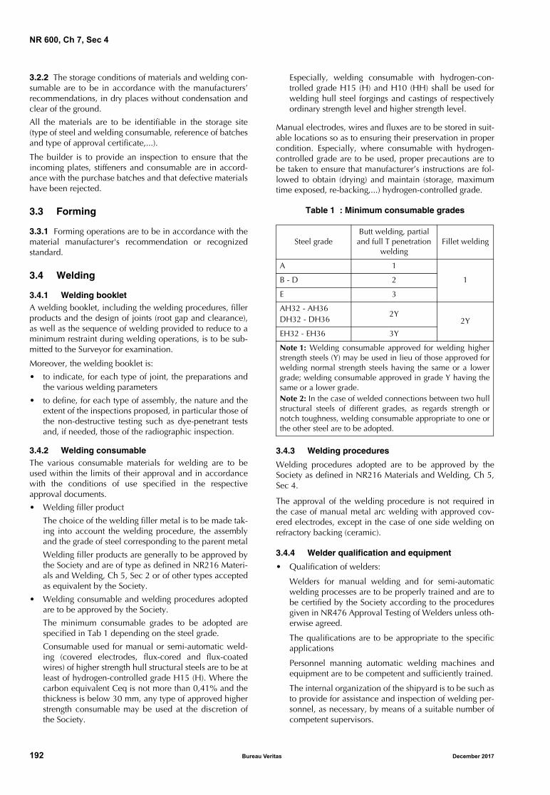
NR 600, Ch 7, Sec 4
3.2.2 The storage conditions of materials and welding con-sumable are to be in accordance with the manufacturers’recommendations, in dry places without condensation andclear of the ground.
All the materials are to be identifiable in the storage site(type of steel and welding consumable, reference of batchesand type of approval certificate,...).
The builder is to provide an inspection to ensure that theincoming plates, stiffeners and consumable are in accord-ance with the purchase batches and that defective materialshave been rejected.
3.3 Forming
3.3.1 Forming operations are to be in accordance with thematerial manufacturer's recommendation or recognizedstandard.
3.4 Welding
3.4.1 Welding bookletA welding booklet, including the welding procedures, fillerproducts and the design of joints (root gap and clearance),as well as the sequence of welding provided to reduce to aminimum restraint during welding operations, is to be sub-mitted to the Surveyor for examination.
Moreover, the welding booklet is:
• to indicate, for each type of joint, the preparations andthe various welding parameters
• to define, for each type of assembly, the nature and theextent of the inspections proposed, in particular those ofthe non-destructive testing such as dye-penetrant testsand, if needed, those of the radiographic inspection.
3.4.2 Welding consumableThe various consumable materials for welding are to beused within the limits of their approval and in accordancewith the conditions of use specified in the respectiveapproval documents.
• Welding filler product
The choice of the welding filler metal is to be made tak-ing into account the welding procedure, the assemblyand the grade of steel corresponding to the parent metal
Welding filler products are generally to be approved bythe Society and are of type as defined in NR216 Materi-als and Welding, Ch 5, Sec 2 or of other types acceptedas equivalent by the Society.
• Welding consumable and welding procedures adoptedare to be approved by the Society.
The minimum consumable grades to be adopted arespecified in Tab 1 depending on the steel grade.
Consumable used for manual or semi-automatic weld-ing (covered electrodes, flux-cored and flux-coatedwires) of higher strength hull structural steels are to be atleast of hydrogen-controlled grade H15 (H). Where thecarbon equivalent Ceq is not more than 0,41% and thethickness is below 30 mm, any type of approved higherstrength consumable may be used at the discretion ofthe Society.
Especially, welding consumable with hydrogen-con-trolled grade H15 (H) and H10 (HH) shall be used forwelding hull steel forgings and castings of respectivelyordinary strength level and higher strength level.
Manual electrodes, wires and fluxes are to be stored in suit-able locations so as to ensuring their preservation in propercondition. Especially, where consumable with hydrogen-controlled grade are to be used, proper precautions are tobe taken to ensure that manufacturer’s instructions are fol-lowed to obtain (drying) and maintain (storage, maximumtime exposed, re-backing,...) hydrogen-controlled grade.
Table 1 : Minimum consumable grades
3.4.3 Welding procedures
Welding procedures adopted are to be approved by theSociety as defined in NR216 Materials and Welding, Ch 5,Sec 4.
The approval of the welding procedure is not required inthe case of manual metal arc welding with approved cov-ered electrodes, except in the case of one side welding onrefractory backing (ceramic).
3.4.4 Welder qualification and equipment
• Qualification of welders:
Welders for manual welding and for semi-automaticwelding processes are to be properly trained and are tobe certified by the Society according to the proceduresgiven in NR476 Approval Testing of Welders unless oth-erwise agreed.
The qualifications are to be appropriate to the specificapplications
Personnel manning automatic welding machines andequipment are to be competent and sufficiently trained.
The internal organization of the shipyard is to be such asto provide for assistance and inspection of welding per-sonnel, as necessary, by means of a suitable number ofcompetent supervisors.
Steel gradeButt welding, partial and full T penetration
weldingFillet welding
A 1
1B - D 2
E 3
AH32 - AH36DH32 - DH36
2Y2Y
EH32 - EH36 3Y
Note 1: Welding consumable approved for welding higherstrength steels (Y) may be used in lieu of those approved forwelding normal strength steels having the same or a lowergrade; welding consumable approved in grade Y having thesame or a lower grade.Note 2: In the case of welded connections between two hullstructural steels of different grades, as regards strength ornotch toughness, welding consumable appropriate to one orthe other steel are to be adopted.
192 Bureau Veritas December 2017
NR 600, Ch 7, Sec 4
Non-destructive tests are to be carried out by qualifiedpersonnel, certified by recognized bodies in compliancewith appropriate standards.
• Equipment:
The welding equipment is to be appropriate to theadopted welding procedures, of adequate output powerand such as to provide for stability of the arc in the dif-ferent welding positions.
In particular, the welding equipment for special weldingprocedures is to be provided with adequate and dulycalibrated measuring instruments, enabling easy andaccurate reading, and adequate devices for easy regula-tion and regular feed.
3.4.5 Weather protection
Adequate protection from the weather is to be provided toparts being welded; in any event, such parts are to be dry.
In welding procedures using bare, cored or coated wireswith gas shielding, the welding is to be carried out inweather protected conditions, so as to ensure that the gasoutflow from the nozzle is not disturbed by winds anddraughts.
3.4.6 Butt connection edge preparation
The edge preparation is to be of the required geometry andcorrectly performed. In particular, if edge preparation is car-ried out by flame, it is to be free from cracks or other detri-mental notches.
3.4.7 Surface condition
The surfaces to be welded are to be free from rust, moistureand other substances, such as mill scale, slag caused byoxygen cutting, grease or paint, which may produce defectsin the welds.
Effective means of cleaning are to be adopted particularly inconnections with special welding procedures; flame ormechanical cleaning may be required.
The presence of a shop primer may be accepted, provided ithas been approved by the Society.
Shop primers are to be approved by the Society for a spe-cific type and thickness according to NR216 Materials andWelding, Ch 5, Sec 3.
3.4.8 Assembling and gap
The plates of the shell and strength deck are generally to bearranged with their length in the fore-aft direction. Possibleexceptions to the above will be considered by the Societyon a case-by-case basis.
The amount of welding to be performed on board is to belimited to a minimum and restricted to easily accessibleconnections.
The setting appliances and system to be used for positioningare to ensure adequate tightening adjustment and an appro-priate gap of the parts to be welded, while allowing maxi-mum freedom for shrinkage to prevent cracks or otherdefects due to excessive restraint.
The gap between the edges is to comply with the requiredtolerances or, when not specified, it is to be in accordancewith normal good practice.
Welds located too close to one another are to be avoided.The minimum distance between two adjacent welds is con-sidered on a case-by-case basis, taking into account thelevel of stresses acting on the connected elements.
3.4.9 Crossing of structural elementIn the case of T crossing of structural elements (one elementcontinuous, the other physically interrupted at the crossing)when it is essential to achieve structural continuity throughthe continuous element (continuity obtained by means ofthe welded connections at the crossing), particular care is tobe devoted to obtaining the correspondence of the inter-rupted elements on both sides of the continuous element.Suitable systems for checking such correspondence are tobe adopted.
3.4.10 Welding sequences and interpass cleaningWelding sequences and direction of welding are to bedetermined so as to minimize deformations and preventdefects in the welded connection.
All main connections are generally to be completed beforethe ship is afloat.
Departures from the above provision may be accepted bythe Society on a case-by-case basis, taking into account anydetailed information on the size and position of welds andthe stresses of the zones concerned, both during shiplaunching and with the ship afloat.
After each run, the slag is to be removed by means of achipping hammer and a metal brush; the same precaution isto be taken when an interrupted weld is resumed or twowelds are to be connected.
3.4.11 PreheatingSuitable preheating, to be maintained during welding, andslow cooling may be required by the Society on a case-by-case basis.
3.5 Inspection and check
3.5.1 GeneralMaterials, workmanship, structures and welded connec-tions are to be subjected, at the beginning of the work, dur-ing construction and after completion, to inspections by theShipyard suitable to check compliance with the applicablerequirements, approved plans and standards.
The manufacturer is to make available to the Surveyor a listof the manual welders and welding operators and theirrespective qualifications.
The manufacturer's internal organization is responsible forensuring that welders and operators are not employedunder improper conditions or beyond the limits of theirrespective qualifications and that welding procedures areadopted within the approved limits and under the appropri-ate operating conditions.
The manufacturer is responsible for ensuring that the oper-ating conditions, welding procedures and work scheduleare in accordance with the applicable requirements,approved plans and recognized good welding practice.
December 2017 Bureau Veritas 193
NR 600, Ch 7, Sec 4
3.5.2 Visual and non-destructive examinations
After completion of the welding operation and workshopinspection, the structure is to be presented to the Surveyorfor visual examination at a suitable stage of fabrication.
As far as possible, the results on non-destructive examina-tions are to be submitted.
Non-destructive examinations are to be carried out withappropriate methods and techniques suitable for the indi-vidual applications, to be agreed with the Surveyor on acase-by-case basis.
Radiographic examinations are to be carried out on thewelded connections of the hull in accordance with [3.5.3].The results are to be made available to the Society. The sur-veyor may require to witness some testing preparations.
The Society may allow radiographic examinations to bereplaced by ultrasonic examinations.
When the visual or non-destructive examinations reveal thepresence of unacceptable indications, the relevant connec-tion is to be repaired to sound metal for an extent andaccording to a procedure agreed with the Surveyor. Therepaired zone is then to be submitted to non-destructiveexamination, using a method deemed suitable by the Sur-veyor to verify that the repair is satisfactory.
Additional examinations may be required by the Surveyoron a case-by-case basis.
Ultrasonic and magnetic particle examinations may also berequired by the Surveyor in specific cases to verify the qual-ity of the base material.
3.5.3 Radiographic inspection
A radiographic inspection is to be carried out on the weldedbutts of shell plating, strength deck plating as well as ofmembers contributing to the longitudinal strength. Thisinspection may also be required for the joints of memberssubject to heavy stresses.
The present requirements constitute general rules: the num-ber of radiographs may be increased where requested by theSurveyor, mainly where visual inspection or radiographicsoundings have revealed major defects, specially for butts ofsheerstrake, stringer plate, bilge strake or keel plate.
Provisions alteration to these rules may be accepted by theSociety when justified by the organization of the shipyard orof the inspection department; the inspection is then to beequivalent to that deduced from the present requirements.
As far as automatic welding of the panels butt welds duringthe pre-manufacturing stage is concerned, the shipyard is tocarry out random non-destructive testing of the welds (radi-ographic or ultrasonic inspection) in order to ascertain theregularity and the constancy of the welding inspection.
In the midship area, radiographies are to be taken at thejoinings of panels.
Each radiography is situated in a butt joint at a cross-shapedwelding.
In a given ship cross-section bounded by the panels, a radi-ography is to be made of each butt of sheerstrake, stringer,bilge and keel plate; in addition, the following radiogra-phies are to be taken:
• bottom plating: two
• deck plating: two
• side shell plating: two each side.
For ships where B + C ≤ 15 m, only one radiography foreach of the above items is required.
This requirement remains applicable where panel butts areshifted or where some strakes are built independently fromthe panels. It is recommended to take most of these radiog-raphies at the intersections of butt and panel seams.
Still in the midship area, a radiographic inspection is to betaken, at random, of the following main members of thestructure:
• butts of continuous longitudinal bulkheads
• butts of longitudinal stiffeners, deck and bottom girderscontributing to the overall strength
• assembly joints of insert plates at the corners of theopenings.
Outwards the midship area, a programme of radiographicinspection at random is to be set up by the shipyard inagreement with the Surveyor for the major points. It is fur-ther recommended:
• to take a number of radiographies of the very thick partsand those comprising restrained joint, such as shaftbrackets, solid keel and its connection to bottom struc-ture, chain plates welding, stabilizer recesses, masts
• to take a complete set of radiographies or to increase thenumber of radiographies for the first joint of a series ofidentical joints. This recommendation is applicable notonly to the assembly joints of prefabricated memberscompleted on the slip, but also to joints completed inthe workshop to prepare such prefabricated members.
Where a radiography is rejected and where it is decided tocarry out a repair, the shipyard is to determine the length ofthe defective part, then a set of inspection radiographies ofthe repaired joint and of adjacent parts is to be taken.Where the repair has been decided by the inspection officeof the shipyard, the film showing the initial defect is to besubmitted to the Surveyor together with the film taken afterrepair of the joint.
3.5.4 Acceptance criteriaThe quality standard adopted by the shipyard is to be sub-mitted to the Society and applies to all constructions unlessotherwise specified on a case-by-case basis.
3.6 Modifications and repairs during con-struction
3.6.1 GeneralDeviations in the joint preparation and other specifiedrequirements, in excess of the permitted tolerances andfound during construction, are to be repaired as agreed withthe Society on a case-by-case basis.
194 Bureau Veritas December 2017
NR 600, Ch 7, Sec 4
3.6.2 Gap and weld deformations
Welding by building up of gaps exceeding the required val-ues and repairs of weld deformations may be accepted bythe Society upon special examination.
3.6.3 Defects
Defects and imperfections on the materials and weldedconnections found during construction are to be evaluatedfor possible acceptance on the basis of the applicablerequirements of the Society.
Where the limits of acceptance are exceeded, the defectivematerial and welds are to be discarded or repaired, asdeemed appropriate by the Surveyor on a case-by-case basis.
When any serious or systematic defect is detected either inthe welded connections or in the base material, the manu-facturer is required to promptly inform the Surveyor andsubmit the repair proposal.
The Surveyor may require destructive or non-destructiveexaminations to be carried out for initial identification ofthe defects found and, in the event that repairs are under-taken, for verification of their satisfactory completion.
3.6.4 Repairs on structure already welded
In the case of repairs involving the replacement of materialalready welded on the hull, the procedures to be adoptedare to be agreed with the Society on a case-by-case basis.
4 Survey for unit production
4.1 General
4.1.1 The survey includes the following steps:
• survey at yard with regards to general requirements of [3]
• structure drawing examination (see [2])
• survey at yard during unit production with regards toapproved drawings, yard's response to comments madeby the Society during structure review examination andconstruction requirements.
These can only focus on the construction stage in progressduring the survey. It is to the responsibility of the inspectiondepartment of the yard to present to the Surveyor anydefects noted during the construction of the ship.
5 Alternative survey scheme for production in large series
5.1 General
5.1.1 Where the hull construction is made in large series,an alternative survey scheme may be agreed with the Soci-ety for hull to be surveyed as far as Classification is con-cerned or hull to be certified by the Society on voluntarybasis.
5.1.2 The general requirements for the alternative surveyscheme, BV Mode I, are given in the Society's Rule NoteNR320 as amended.
5.2 Type approval
5.2.1 GeneralThe type approval of a hull made of steel and built in largeseries comprises:
• examination, in accordance with the present Rule Noteof drawings and documents defining the main structuralcomponents of the hull
• examination of certain items of equipment and their fit-tings if requested by the Society Rules for the classifica-tion and/or certification of ships
• inspection of the first hull (or a hull representing thelarge series production).
5.2.2 Examination of drawingsThe structure drawing examination is to be carried out asdefined in [2].
5.2.3 Examination of certain items of equipmentThe equipment requiring a particular drawing examinationis defined in the present Rule. As a general rule, this equip-ment consists mainly in portholes, deck hatches and doors.
This examination may be carried out as defined in the Soci-ety’s Rules or through an homologation process, at the satis-faction of the Society.
5.2.4 InspectionsThe purpose of the inspections, carried out by a Surveyor ofthe Society on the initial hull of the series (or a representa-tive hull of the series), is to make surveys at yard during unitproduction with regards to approved drawings, yard'sresponse to comments made by the Society during structurereview examination and construction requirements as listedin [3].
5.2.5 Type Approval CertificateA Type Approval Certificate (TAC) is issued for the initialhull covered by the type approval procedure.
5.3 Quality system documentation
5.3.1 The quality system documentation submitted to theSociety is to include the information required in [3.1] and inthe Rule Note NR320 as amended.
5.4 Manufacturing, testing and inspection plan (MTI plan)
5.4.1 For each type of hull, the manufacturing, testing andinspection plan is to detail specifically:
• Materials:
Special requirements of the supplier (storage conditions,type of checks to be performed on incoming productsand properties to be tested by the yard before use).
- Storage conditions:
Information about storage sites (ventilation condi-tions to avoid condensation, supplier data sheetsspecifying the storage conditions, listing documentsto record arrival and departure dates for consign-ment).
December 2017 Bureau Veritas 195
NR 600, Ch 7, Sec 4
- Reception:
Information about consignment (traceability of con-signment specifying date of arrival, type of inspec-tion, check on product packaging, types of specifictests performed).
- Traceability:
Description of the yard process to ensure traceabilityof the materials from the time of the reception to theend of the production operations.
• Hull construction:
Description of the yard process to ensure that the scant-lings and construction meet the rule requirements inrelation to the approved drawings.
• Installation of internal structure:
Information about the main operations of the internalstructure installation.
• Equipment:
The main equipment to be covered by the rules of theSociety are portholes, windows and deck hatches,watertight doors, independent tanks and rudders, thescheduled tests and traceability on the equipment uponarrival and/or after installation.
• Testing and damage reference documents:For all the previously defined MTI plan processes, pro-cedures are to be written, defining the types of tests orinspections performed, the acceptance criteria and themeans of handling non-conformities.
5.5 Society’s certificate
5.5.1 Certificate of recognitionAfter completion of the examination, by the Society, of thequality assurance manual, the MTI plan and the yard audit,a Certificate of recognition may be granted as per the provi-sions of NR320 Classification Scheme of Materials & Equip-ment, as amended.
5.5.2 Certificate of conformityEach hull may be certified individually upon request madeto the Society.
5.6 Other certification scheme for produc-tion in large series
5.6.1 Other certification scheme for production in largeseries, based on NR320 Classification Scheme of Materials& Equipment may be considered by the Society on a caseby case basis.
196 Bureau Veritas December 2017