Hull Arrangement, Stability and Systems for Ships less than 500 GT
190
Hull Arrangement, Stability and Systems for Ships less than 500 GT February 2014 Rule Note NR 566 DT R01 E Marine & Offshore Division 92571 Neuilly sur Seine Cedex - France Tel: + 33 (0)1 55 24 70 00 – Fax: + 33 (0)1 55 24 70 25 Marine website: http://www.veristar.com Email: [email protected] © 2014 Bureau Veritas – All rights reserved
Transcript of Hull Arrangement, Stability and Systems for Ships less than 500 GT

Hull Arrangement, Stability and System s for Ships less than 500 GT
February 2014
Rule Note NR 566 DT R01 E
Marine & Offshore Division
92571 Neuilly sur Seine Cedex - France Tel: + 33 (0)1 55 24 70 00 – Fax: + 33 (0)1 55 24 7 0 25
Marine website: http://www.veristar.com Email: [email protected]
© 2014 Bureau Veritas – All rights reserved

ARTICLE 1
1.1. - BUREAU VERITAS is a Society the purpose of whose Marine & Offshore Division (the "Society") isthe classification (" Classification ") of any ship or vessel or offshore unit or structure of any type or part ofit or system therein collectively hereinafter referred to as a "Unit" whether linked to shore, river bed or seabed or not, whether operated or located at sea or in inland waters or partly on land, including submarines,hovercrafts, drilling rigs, offshore installations of any type and of any purpose, their related and ancillaryequipment, subsea or not, such as well head and pipelines, mooring legs and mooring points or otherwiseas decided by the Society.The Society:
• "prepares and publishes Rules for classification, Guidance Notes and other documents (" Rules ");
• "issues Certificates, Attestations and Reports following its interventions (" Certificates ");• "publishes Registers.
1.2. - The Society also participates in the application of National and International Regulations or Stand-ards, in particular by delegation from different Governments. Those activities are hereafter collectively re-ferred to as " Certification ".1.3. - The Society can also provide services related to Classification and Certification such as ship andcompany safety management certification; ship and port security certification, training activities; all activi-ties and duties incidental thereto such as documentation on any supporting means, software, instrumen-tation, measurements, tests and trials on board.
1.4. - The interventions mentioned in 1.1., 1.2. and 1.3. are referred to as " Services ". The party and/or itsrepresentative requesting the services is hereinafter referred to as the " Client ". The Services are pre-pared and carried out on the assumption that the Clients are aware of the International Maritimeand/or Offshore Industry (the "Industry") practices.
1.5. - The Society is neither and may not be considered as an Underwriter, Broker in ship's sale or char-tering, Expert in Unit's valuation, Consulting Engineer, Controller, Naval Architect, Manufacturer, Ship-builder, Repair yard, Charterer or Shipowner who are not relieved of any of their expressed or impliedobligations by the interventions of the Society.ARTICLE 2
2.1. - Classification is the appraisement given by the Society for its Client, at a certain date, following sur-veys by its Surveyors along the lines specified in Articles 3 and 4 hereafter on the level of compliance ofa Unit to its Rules or part of them. This appraisement is represented by a class entered on the Certificatesand periodically transcribed in the Society's Register.
2.2. - Certification is carried out by the Society along the same lines as set out in Articles 3 and 4 hereafterand with reference to the applicable National and International Regulations or Standards.
2.3. - It is incumbent upon the Client to maintain the condition of the Unit after surveys, to presentthe Unit for surveys and to inform the Society without delay of circumstances which may affect thegiven appraisement or cause to modify its scope.2.4. - The Client is to give to the Society all access and information necessary for the safe and efficientperformance of the requested Services. The Client is the sole responsible for the conditions of presenta-tion of the Unit for tests, trials and surveys and the conditions under which tests and trials are carried out.
ARTICLE 33.1. - The Rules, procedures and instructions of the Society take into account at the date of theirpreparation the state of currently available and proven technical knowledge of the Industry. Theyare a collection of minimum requirements but not a standard or a code of construction neither aguide for maintenance, a safety handbook or a guide of professional practices, all of which areassumed to be known in detail and carefully followed at all times by the Client.Committees consisting of personalities from the Industry contribute to the development of those docu-ments.3.2. - The Society only is qualified to apply its Rules and to interpret them. Any reference to themhas no effect unless it involves the Society's intervention.3.3. - The Services of the Society are carried out by professional Surveyors according to the applicableRules and to the Code of Ethics of the Society. Surveyors have authority to decide locally on matters re-lated to classification and certification of the Units, unless the Rules provide otherwise.
3.4. - The operations of the Society in providing its Services are exclusively conducted by way of ran-dom inspections and do not in any circumstances involve monitoring or exhaustive verification.
ARTICLE 44.1. - The Society, acting by reference to its Rules:
• "reviews the construction arrangements of the Units as shown on the documents presented by the Cli-ent;
• "conducts surveys at the place of their construction;
• "classes Units and enters their class in its Register;• "surveys periodically the Units in service to note that the requirements for the maintenance of class are
met. The Client is to inform the Society without delay of circumstances which may cause the date or theextent of the surveys to be changed.ARTICLE 5
5.1. - The Society acts as a provider of services. This cannot be construed as an obligation bearingon the Society to obtain a result or as a warranty.
5.2. - The certificates issued by the Society pursuant to 5.1. here above are a statement on the levelof compliance of the Unit to its Rules or to the documents of reference for the Services provided for.
In particular, the Society does not engage in any work relating to the design, building, productionor repair checks, neither in the operation of the Units or in their trade, neither in any advisory serv-ices, and cannot be held liable on those accounts. Its certificates cannot be construed as an im-plied or express warranty of safety, fitness for the purpose, seaworthiness of the Unit or of its valuefor sale, insurance or chartering.
5.3. - The Society does not declare the acceptance or commissioning of a Unit, nor of its construc-tion in conformity with its design, that being the exclusive responsibility of its owner or builder.
5.4. - The Services of the Society cannot create any obligation bearing on the Society or constitute anywarranty of proper operation, beyond any representation set forth in the Rules, of any Unit, equipment ormachinery, computer software of any sort or other comparable concepts that has been subject to any sur-vey by the Society.
ARTICLE 6
6.1. - The Society accepts no responsibility for the use of information related to its Services which was notprovided for the purpose by the Society or with its assistance.
6.2. - If the Services of the Society or their omission cause to the Client a damage which is provedto be the direct and reasonably foreseeable consequence of an error or omission of the Society,its liability towards the Client is limited to ten times the amount of fee paid for the Service havingcaused the damage, provided however that this limit shall be subject to a minimum of eight thou-sand (8,000) Euro, and to a maximum which is the greater of eight hundred thousand (800,000)Euro and one and a half times the above mentioned fee. These limits apply regardless of fault in-cluding breach of contract, breach of warranty, tort, strict liability, breach of statute, etc.The Society bears no liability for indirect or consequential loss whether arising naturally or not asa consequence of the Services or their omission such as loss of revenue, loss of profit, loss of pro-duction, loss relative to other contracts and indemnities for termination of other agreements.
6.3. - All claims are to be presented to the Society in writing within three months of the date when the Serv-ices were supplied or (if later) the date when the events which are relied on of were first known to the Client,and any claim which is not so presented shall be deemed waived and absolutely barred. Time is to be in-terrupted thereafter with the same periodicity. ARTICLE 7
7.1. - Requests for Services are to be in writing.
7.2. - Either the Client or the Society can terminate as of right the requested Services after givingthe other party thirty days' written notice, for convenience, and without prejudice to the provisionsin Article 8 hereunder.
7.3. - The class granted to the concerned Units and the previously issued certificates remain valid until thedate of effect of the notice issued according to 7.2. here above subject to compliance with 2.3. here aboveand Article 8 hereunder.7.4. - The contract for classification and/or certification of a Unit cannot be transferred neither assigned.
ARTICLE 8
8.1. - The Services of the Society, whether completed or not, involve, for the part carried out, the paymentof fee upon receipt of the invoice and the reimbursement of the expenses incurred.
8.2. - Overdue amounts are increased as of right by interest in accordance with the applicable leg-islation.
8.3. - The class of a Unit may be suspended in the event of non-payment of fee after a first unfruitfulnotification to pay.
ARTICLE 9
9.1. - The documents and data provided to or prepared by the Society for its Services, and the informationavailable to the Society, are treated as confidential. However:
• "Clients have access to the data they have provided to the Society and, during the period of classifica-tion of the Unit for them, to the classification file consisting of survey reports and certificates which have been prepared at any time by the Society for the classification of the Unit ;
• "copy of the documents made available for the classification of the Unit and of available survey reports can be handed over to another Classification Society, where appropriate, in case of the Unit's transfer of class;
• "the data relative to the evolution of the Register, to the class suspension and to the survey status of the Units, as well as general technical information related to hull and equipment damages, may be passed on to IACS (International Association of Classification Societies) according to the association working rules;
• "the certificates, documents and information relative to the Units classed with the Society may be reviewed during certificating bodies audits and are disclosed upon order of the concerned governmen-tal or inter-governmental authorities or of a Court having jurisdiction.
The documents and data are subject to a file management plan.
ARTICLE 10
10.1. - Any delay or shortcoming in the performance of its Services by the Society arising from an eventnot reasonably foreseeable by or beyond the control of the Society shall be deemed not to be a breach ofcontract.
ARTICLE 11
11.1. - In case of diverging opinions during surveys between the Client and the Society's surveyor, the So-ciety may designate another of its surveyors at the request of the Client.
11.2. - Disagreements of a technical nature between the Client and the Society can be submitted by theSociety to the advice of its Marine Advisory Committee.
ARTICLE 1212.1. - Disputes over the Services carried out by delegation of Governments are assessed within theframework of the applicable agreements with the States, international Conventions and national rules.12.2. - Disputes arising out of the payment of the Society's invoices by the Client are submitted to the Courtof Nanterre, France, or to another Court as deemed fit by the Society.12.3. - Other disputes over the present General Conditions or over the Services of the Society areexclusively submitted to arbitration, by three arbitrators, in London according to the ArbitrationAct 1996 or any statutory modification or re-enactment thereof. The contract between the Societyand the Client shall be governed by English law.
ARTICLE 13
13.1. - These General Conditions constitute the sole contractual obligations binding together theSociety and the Client, to the exclusion of all other representation, statements, terms, conditionswhether express or implied. They may be varied in writing by mutual agreement. They are not var-ied by any purchase order or other document of the Client serving similar purpose.13.2. - The invalidity of one or more stipulations of the present General Conditions does not affect the va-lidity of the remaining provisions. 13.3. - The definitions herein take precedence over any definitions serving the same purpose which mayappear in other documents issued by the Society.
BV Mod. Ad. ME 545 L - 7 January 2013
MARINE & OFFSHORE DIVISIONGENERAL CONDITIONS

RULE NOTE NR 566
NR 566Hull Arrangement, Stability and Systems for
Ships less than 500 GT
Chapters 1 2 3 4
Chapter 1 GENERAL ARRANGEMENT DESIGN, STABILITY, HULL INTEGRITY
Chapter 2 MACHINERY
Chapter 3 ELECTRICITY AND AUTOMATION
Chapter 4 FIRE SAFETY
February 2014

eSe
Unless otherwise specified, these rulsigned after February 1st, 2014. The before February 1st, 2014, as and wh
2 Bureau V
s apply to ships for which contracts areociety may refer to the contents hereofn deemed necessary or appropriate.
eritas February 2014

CHAPTER 1GENERAL ARRANGEMENT DESIGN, STABILITY, HULL INTEGRITY
Section 1 General Requirements
1 General 25
1.1 Application1.2 Symbols1.3 Definitions
Section 2 General Arrangement Design
1 Subdivision arrangement 29
1.1 Number of watertight bulkheads1.2 Collision bulkhead1.3 Height of transverse watertight bulkheads1.4 Openings in watertight bulkheads and decks
2 Compartment arrangement 30
2.1 Cofferdams2.2 Double bottoms2.3 Compartments forward of the collision bulkhead2.4 Shaft tunnels
3 Access arrangement 31
3.1 General3.2 Double bottoms
4 Helicopter facilities 32
4.1 General
5 Accommodation 32
5.1 Seating of crew boats
6 Crew protection 32
6.1 Bulwarks and guard rails
Section 3 Stability
1 General 33
1.1 Application1.2 Relaxation
2 Intact stability 33
2.1 Requirements
February 2014 Bureau Veritas 3

3 Damage stability 33
3.1 General3.2 Damage dimensions 3.3 Progressive flooding3.4 Minor damage3.5 Permeabilities3.6 Survival requirements3.7 Damage stability criteria3.8 Heeling moments
Section 4 Hull Integrity
1 General 35
1.1 Application
2 External openings 35
2.1 General2.2 Bow doors, inner doors, side doors and stern doors
3 Sidescuttles, windows and skylights 35
3.1 General3.2 Opening arrangement3.3 Glasses3.4 Deadlight arrangement
4 Discharges 36
4.1 Arrangement of discharges4.2 Arrangement of garbage chutes4.3 Scantlings of garbage chutes4.4 Scuppers4.5 Pipe discharges4.6 Specific arrangements4.7 Summary table of scupper and overboard discharge arrangements
5 Machinery space openings 39
5.1 Closing devices5.2 Coamings
6 Companionway 39
6.1 General6.2 Scantlings6.3 Closing devices
7 Hatches 40
7.1 Hatchways
8 Ventilation openings 40
8.1 Ventilation openings8.2 Coamings
9 Air pipes 41
9.1 General
4 Bureau Veritas February 2014

10 Tank cleaning openings 41
10.1 General
11 Freeing ports 41
11.1 General11.2 Ships of less than 24 m in length
12 Minimum bow height 42
12.1 General
February 2014 Bureau Veritas 5

CHAPTER 2MACHINERY
Section 1 General Requirements and Application
1 General 47
1.1 Application1.2 Documentation to be submitted1.3 Definitions
2 Design and construction 47
2.1 General2.2 Materials, welding and testing2.3 Vibrations 2.4 Operation in inclined position2.5 Ambient conditions2.6 Power of machinery2.7 Astern power2.8 Safety devices2.9 Fuels
3 Arrangement and installation on board 49
3.1 General3.2 Gratings3.3 Bolting down3.4 Safety devices on moving parts3.5 Gauges3.6 Ventilation in engine or machinery spaces3.7 Hot surfaces and fire protection3.8 Machinery remote control, alarms3.9 Pressure vessels
4 Tests and trials 50
4.1 Works tests4.2 Trials on board
Section 2 Propelling and Auxiliary Machinery
1 General provisions 51
1.1 Scope1.2 Documents to be submitted
2 Internal combustion engines 51
2.1 General2.2 Installation2.3 Starting systems2.4 Control - Safety - Monitoring and instrumentation
3 Reduction gear - Transmissions 54
3.1 General3.2 Design and construction
6 Bureau Veritas February 2014
4 Shafting 54
4.1 General4.2 Shafting scantling4.3 Shafting accessories
5 Propeller 57
5.1 Scantlings
6 Shaft vibrations 57
6.1 General
7 Shaft alignment 57
7.1 General
8 Thrusters and waterjets 57
8.1 General
Section 3 Steering Gear
1 General 58
1.1 Application1.2 Documentation to be submitted1.3 Definitions1.4 Symbols
2 Design and construction - Mechanical, hydraulical and electrical systems 60
2.1 Mechanical systems2.2 Hydraulical systems2.3 Electrical systems2.4 Control, monitoring and alarm systems
3 Design and construction - Performance and availability 64
3.1 General provisions3.2 Performance and power operation of the steering gear3.3 Control of the steering gear3.4 Arrangement of main and auxiliary steering gears3.5 Autopilot
4 Design and construction - Requirements for ships equipped with several rudders 65
4.1 Principle4.2 Synchronisation
5 Design and construction - Requirements for ships equipped with thrusters as steering means 66
5.1 Principle5.2 Use of azimuth thrusters5.3 Use of water-jets
6 Arrangement and installation 66
6.1 Steering gear room arrangement6.2 Rudder actuator installation6.3 Overload protections6.4 Means of communication6.5 Operating instructions
February 2014 Bureau Veritas 7
7 Certification, inspection and testing 67
7.1 Type tests of hydraulic pumps7.2 Testing of materials7.3 Inspection and tests during manufacturing7.4 Inspection and tests after completion
Section 4 Arrangement and Installation of Piping Systems
1 General 69
1.1 Application1.2 Documentation to be submitted1.3 Definitions1.4 Symbols and units1.5 Class of piping systems1.6 Materials
2 Design of metallic piping systems 72
2.1 General2.2 Thickness of pressure piping2.3 Junction of metallic pipes2.4 Welding and bending of metallic piping
3 Design of plastic piping systems 81
3.1 General3.2 Definitions3.3 Strength3.4 Fire safety characteristics3.5 Pipe and fitting connections3.6 Arrangement and installation of plastic pipes3.7 Certification
4 Design of flexible piping systems 84
4.1 General4.2 Design
5 Arrangement and installation of piping systems 85
5.1 General5.2 Protection against overpressure5.3 Flexible hoses and expansion joints5.4 Valves and accessories5.5 Control and monitoring5.6 Location of tanks and piping system components5.7 Passage through watertight bulkheads or decks5.8 Independence of lines5.9 Prevention of progressive flooding5.10 Provision for expansion5.11 Supporting of the pipes5.12 Protection of pipes5.13 Additional arrangements for flammable fluids
6 Certification, inspection and testing of piping systems 91
6.1 Application6.2 Applicable Rules
8 Bureau Veritas February 2014

Section 5 Hull Piping
1 Bilge system 92
1.1 General1.2 Pumps and ejectors1.3 Size of bilge pipes1.4 Alternative arrangement1.5 Arrangement of bilge lines and their accessories1.6 Bilge pumping after flooding
2 Scuppers and discharges 94
2.1 Principle2.2 Definitions2.3 Scupper and discharge arrangement
3 Air, sounding and overflow pipes 94
3.1 General3.2 Air pipes3.3 Sounding pipes3.4 Overflow pipes
Section 6 Fuel Oil Systems
1 General 97
1.1 Applications1.2 Principle1.3 General arrangements
2 Oil fuel system design 97
2.1 Application2.2 General provisions2.3 Oil fuel tank and bunkers2.4 Filling and transfer pipes2.5 Oil fuel tanks and bunkers2.6 Oil fuel supply to engines2.7 Control and monitoring
3 Ships of 12 m in length and over 100
3.1 Application3.2 Principles
4 Ships of 24 m in length and over 100
4.1 Application4.2 Design of fuel supply systems
Section 7 Other Systems
1 General 101
1.1 Application
February 2014 Bureau Veritas 9

2 Cooling systems 101
2.1 Application2.2 Principle2.3 Design of sea water cooling systems2.4 Design of fresh water cooling systems2.5 Arrangement of cooling systems
3 Ballast systems 102
3.1 Applications3.2 Design of ballast systems3.3 Ballast pumping arrangement
4 Lubricating oil systems 102
4.1 Application4.2 Principle4.3 Design of oil lubrication and oil control systems4.4 Design of lubricating oil tanks4.5 Construction of lubricating oil piping systems
5 Hydraulic systems 103
5.1 Application5.2 General5.3 General5.4 Design of hydraulic pumps and accessories5.5 Design of hydraulic tanks and other components5.6 Control and monitoring
6 Compressed air systems 105
6.1 Application6.2 Principle6.3 Design of starting air systems6.4 Design of control and monitoring air systems6.5 Design of air compressor6.6 Control and monitoring of compressed air systems6.7 Arrangement of compressed air piping systems
7 Exhaust gas systems 107
7.1 General 7.2 Design of exhaust systems7.3 Arrangement of exhaust piping systems
8 Ventilation 108
8.1 General 8.2 Design of ventilation systems8.3 Arrangement of ventilation systems
Section 8 Tests, Inspection and Seatrials
1 General 109
1.1 Application1.2 Purpose of shipboard tests1.3 Documentation to be submitted
2 General requirements for shipboard tests 109
2.1 Trials at the moorings2.2 Sea trials
10 Bureau Veritas February 2014

3 Shipboard tests for machinery 109
3.1 Conditions of sea trials3.2 Navigation and manoeuvring tests3.3 Tests of diesel engines3.4 Tests of electric propulsion system3.5 Tests of gears3.6 Tests of main propulsion shafting and propellers3.7 Tests of piping systems3.8 Tests of steering gear
4 Inspection of machinery after sea trials 113
4.1 General4.2 Diesel engines
February 2014 Bureau Veritas 11

CHAPTER 3ELECTRICITY AND AUTOMATION
Section 1 General Requirements and Application
1 General 117
1.1 Application1.2 References to other regulations and standards1.3 Innovative designs
2 Documentation to be submitted 117
2.1
3 Definitions 118
3.1 General3.2 Essential services3.3 Low-voltage systems3.4 Safety voltage3.5 DC systems of distribution3.6 AC systems of distribution3.7 Hull return system3.8 Earthed3.9 Main source of electrical power3.10 Main switchboard3.11 Emergency source of electrical power3.12 Emergency condition3.13 Emergency switchboard3.14 Normal operational and habitable condition3.15 Distribution board3.16 Engine negative terminal3.17 Final circuit3.18 Overcurrent protection device3.19 Circuit breaker3.20 Generator3.21 Generating set3.22 Fuse3.23 Protective conductor3.24 Bond 3.25 Neutral conductor3.26 Sheath3.27 Batteries3.28 Cable trunking3.29 Captive-spade terminal3.30 Accessible3.31 Readily accessible3.32 Certified safe-type equipment
4 Environmental conditions 120
4.1 General4.2 Ambient air temperatures4.3 Humidity
12 Bureau Veritas February 2014
4.4 Sea water temperatures4.5 Salt mist4.6 Inclinations4.7 Vibrations
5 Quality of power supply 121
5.1 General5.2 a.c. distribution systems5.3 d.c. distribution systems5.4 Harmonic distortions
6 Electromagnetic compatibility 122
6.1
7 Materials 122
7.1 General7.2 Insulating materials for windings7.3 Insulating materials for cables
Section 2 System Design
1 Supply systems and characteristics of the supply 124
1.1 Supply systems1.2 Maximum voltage
2 Sources of electrical power 125
2.1 Ships of less than 12 m in length2.2 Main source of electrical power2.3 Additional requirements for passenger ships and for other ships of 24 m in
length and over2.4 Emergency source of electrical power
3 Distribution 127
3.1 Earthed neutral systems3.2 Insulated systems3.3 A.C. distribution system3.4 D.C. distribution system supplied from batteries3.5 Emergency distribution of electrical power3.6 Specific requirements for ro-ro passenger ships3.7 Shore connection3.8 Supply of motors3.9 Power supply to lighting installations3.10 Navigation and signalling lights3.11 General alarm 3.12 Internal communications3.13 Bilge level alarms3.14 Specific requirements for special power services 3.15 Diesel engine starting system3.16 Specific requirements for ships with electric propulsion3.17 Watertight doors below the bulkhead deck3.18 Lightning protection
4 Degrees of protection of equipment and enclosures 132
4.1 General
February 2014 Bureau Veritas 13

5 Diversity factors 133
5.1 General
6 Electrical protection 133
6.1 Protection against overcurrent6.2 Localisation of protection6.3 Protection of generators6.4 Protection of final circuits6.5 Protection of motors6.6 Protection of storage batteries6.7 Protection of transformers6.8 Protection of measuring instruments, pilot lamps and control circuits6.9 Special applications
7 Electrical cables 135
7.1 General7.2 Conductors7.3 Choice of protective covering7.4 Cables for submerged bilge pumps7.5 Internal wiring of switchboards and other enclosures for equipment7.6 Current carrying capacity of cables7.7 Minimum nominal cross-sectional area of conductors7.8 Choice of cables7.9 Parallel connection of cables
8 Electrical equipment for use in explosive atmospheres 137
8.1 General8.2 Electrical installations in battery rooms8.3 Electrical installations in paint stores or enclosed spaces leading to paint stores8.4 Protection against combustible dust hazard8.5 Electrical installations on cardecks for ro-ro passenger ships
Section 3 Equipment
1 General 139
1.1 Construction1.2 Degree of protection of enclosures
2 Switchboards 139
2.1 Design - Construction2.2 Busbars2.3 Auxiliary circuits2.4 Instruments2.5 Testing
3 Rotating electrical machines 141
3.1 General3.2 D.C. generators3.3 A.C. generators3.4 Prime movers, speed control3.5 Testing
4 Transformers 142
4.1 General4.2 Construction4.3 Testing
14 Bureau Veritas February 2014
5 Converters/inverters 142
5.1 General5.2 Construction
6 Constructional requirements for batteries and chargers 142
6.1 General6.2 Vented batteries6.3 Valve-regulated sealed batteries6.4 Tests on batteries6.5 Chargers
7 Accessories 143
7.1 Plugs and socket-outlets7.2 Lighting fittings7.3 Electrical heating and cooking appliances
Section 4 Location and Installation
1 General requirements 144
1.1 IP and environmental categories1.2 Areas with a risk of explosion
2 Main electrical system 144
2.1 Location in relation to the emergency system2.2 Main switchboard
3 Emergency electrical system 144
3.1 Spaces for the emergency source3.2 Emergency switchboard3.3 Emergency battery
4 Distribution boards 144
4.1 Distribution boards for cargo spaces and similar spaces4.2 Distribution board for navigation lights
5 Storage batteries 144
5.1 General5.2 Large vented batteries5.3 Moderate vented batteries5.4 Small vented batteries5.5 Ventilation
6 Protection against injury or damage 146
6.1 Protection against injury or damage caused by electrical equipment6.2 Protection against damage to electrical equipment6.3 Accessibility
7 Earthing of non-current carrying parts 146
7.1 General7.2 Parts which are to be earthed7.3 Earthing connection7.4 Earthed distribution system7.5 Bonding connections
February 2014 Bureau Veritas 15
8 Converters - Transformers 147
8.1 Semiconductor power converters8.2 Transformers
9 Switchboards 148
9.1 General9.2 Emergency switchboard
10 Cables 148
10.1 General10.2 Cable runs10.3 Radius of bend10.4 Cable support and protection10.5 Penetration of bulkheads and decks10.6 Earthing and continuity of metal coverings of cables10.7 Earthing and continuity of metal pipes, conduits and trunking or casings10.8 Cable trays/protective casings/conduits made of plastics materials
11 Cabling and wiring 149
11.1 Cable terminations11.2 D.c. and a.c. segregation11.3 Conductor identification
12 Various appliances 150
12.1 Lighting fittings12.2 Heating appliances12.3 Magnetic compass12.4 Socket-outlets
Section 5 Automation - General Requirements
1 General 151
1.1 Field of application1.2 Regulations and standards1.3 Definitions1.4 General
2 Documentation 152
2.1 General
3 Environmental and supply conditions 152
3.1
4 Materials and construction 152
4.1 General
Section 6 Automation - Design Requirements
1 General requirements 153
1.1 General
2 Control of machinery 153
2.1 General requirements 2.2 Control of propulsion machinery
16 Bureau Veritas February 2014
3 Power supply of automation system 154
3.1
4 Alarm system 154
4.1 General requirements4.2 Alarm functions
5 Safety system 155
5.1 Design5.2 Function5.3 Shutdown
Section 7 Testing
1 General 156
1.1 Rule application
2 Type approved components 156
2.1
3 Insulation resistance 156
3.1 Insulation-testing instruments3.2 Switchboards3.3 Lighting and power circuits3.4 Generators and motors3.5 Internal communication circuits
4 Earth 157
4.1 Electrical constructions4.2 Metal-sheathed cables, metal pipes or conduits
5 Operational tests 157
5.1 General5.2 Voltage drop5.3 Switchgear5.4 Consuming devices5.5 Emergency source of electrical power5.6 Other systems5.7 Generating sets and their protective devices
February 2014 Bureau Veritas 17
CHAPTER 4FIRE SAFETY
Section 1 General Requirements and Application
1 Application 161
1.1 General
2 Passenger ships 161
2.1 Applicable Rules2.2 Applicable requirements for passenger ships with navigation notation coastal
area
3 Crew boats 162
3.1 Applicable Rules3.2 Specific requirements
4 Other ships 162
4.1 Applicable Rules4.2 Documentation to be submitted4.3 Type approved products4.4 Definitions
5 Helicopter facilities 166
5.1
Section 2 Prevention of Fire
1 General 167
1.1 Application
2 Probability of ignition 167
2.1 Machinery spaces2.2 Other ignition sources
3 Fire growth potential and control of smoke spread: requirements for materials 167
3.1 Material of hull, superstructures, structural bulkheads, decks and deckhouses3.2 Machinery spaces boundaries3.3 Fire divisions3.4 Insulation materials3.5 Primary deck coverings3.6 Surface materials and adhesives3.7 Additional requirements for crew boat
Section 3 Suppression of Fire: Detection and Alarm
1 General 170
1.1 Application
18 Bureau Veritas February 2014

2 Initial and periodical tests 170
2.1 General
3 Protection of engine spaces and machinery spaces of category A 170
3.1 Installation3.2 Design
4 Protection of accommodation and service spaces 170
4.1
5 Design of the fixed fire detection and fire alarm systems 170
5.1 Engineering specifications
Section 4 Suppression of Fire: Containment of Fire
1 General 173
1.1 Application
2 Thermal and structural boundaries 173
2.1 General2.2 Fire integrity of decks and bulkheads
3 Penetrations in fire-resisting divisions and prevention of heat transmission 175
3.1 Penetrations in A and B class divisions or equivalent3.2 Prevention of heat transmission
4 Protection of openings in fire-resisting divisions 175
4.1 Openings in bulkheads and decks
5 Ventilation systems 176
5.1 Ventilation controls5.2 Duct and dampers5.3 Arrangements of ducts5.4 Exhaust ducts from galley ranges
Section 5 Suppression of Fire: Fire Fighting
1 General 178
1.1 Application
2 Water supply systems 178
2.1 General2.2 Fire pumps2.3 Fire main and hydrants2.4 Fire hoses and nozzles
3 Portable fire extinguishers 180
3.1 Type and design3.2 Arrangement of fire extinguishers
February 2014 Bureau Veritas 19

4 Fixed fire-extinguishing systems 181
4.1 Types of fixed fire-extinguishing systems4.2 Fire-extinguishing arrangements in machinery spaces4.3 Other systems
Section 6 Escape
1 General 182
1.1 Application
2 General requirements 182
2.1 Number of means of escape2.2 Lifts2.3 Accessibility of escape routes
3 Ships of less than 12 m in length 182
3.1 Escape routes arrangement
4 Ships of 12 m in length and over 182
4.1 Means of escape from control stations, accommodation spaces and service spaces
4.2 Means of escape from machinery spaces4.3 Means of escape from vehicle, special category and ro-ro spaces
Section 7 Fire Control Plans
1 General 184
1.1 Application
2 Fire control plans 184
2.1 Description of plans2.2 Location of the fire control plan
Section 8 Protection of Vehicle, Special Category and Ro-Ro Spaces
1 General requirements and application 185
1.1 Application1.2 Definitions
2 Ventilation 185
2.1 Application2.2 Capacity of ventilation systems2.3 Performance of ventilation systems2.4 Indication of ventilation systems2.5 Closing appliances and ducts
3 Electrical equipment 186
3.1 Application3.2 Protection of electrical equipment
20 Bureau Veritas February 2014
4 Detection and alarm 186
4.1 Application4.2 Fixed fire detection and alarm system
5 Fire extinction 186
5.1 Application5.2 Fixed water spray system
Section 9 Alternative Design and Arrangements
1 General 187
1.1 Purposes1.2 General1.3 Fire safety objectives
2 Alternative design and arrangements 187
2.1 Engineering analysis2.2 Evaluation of the alternative design and arrangements2.3 Re-evaluation due to change of conditions
February 2014 Bureau Veritas 21

22 Bureau Veritas February 2014
NR 566
Chapter 1
GENERAL ARRANGEMENT DESIGN,STABILITY, HULL INTEGRITY
SECTION 1 GENERAL REQUIREMENTS
SECTION 2 GENERAL ARRANGEMENT DESIGN
SECTION 3 STABILITY
SECTION 4 HULL INTEGRITY
February 2014 Bureau Veritas 23

24 Bureau Ve
ritas February 2014
NR 566, Ch 1, Sec 1
SECTION 1 GENERAL REQUIREMENTS
1 General
1.1 Application
1.1.1 Requirements of these rules are specific to ships andnon-propelled units of less than 500 GT without restrictionin hull construction material.However, the following types of ships are not covered bythese rules (see separate rules):• Passenger ships with unrestricted navigation (see NR467
Rules for Steel Ships, Part D, Chapter 11)• Ro-ro passenger ships with unrestricted navigation (see
NR467 Rules for Steel Ships, Part D, Chapter 12)• Fishing vessels (see NR467 Rules for Steel Ships, Part D,
Chapter 20)• High speed craft (see NR396 Rules for High Speed Craft)• Yachts (see NR500 Rules for Yachts)• Chemical tankers (see NR467 Rules for Steel Ships, Part D,
Chapter 8)• Liquefied gas carriers (see NR467 Rules for Steel Ships,
Part D, Chapter 9).
1.1.2 When the administration of the state whose flag theship is entitled to fly refers to specific rules covering thesubjects in Chapter 1 to Chapter 4, the Society may acceptthese rules in lieu of the present Rules.In such cases a special notation regarding the above isentered on the Certificate of Class of the ship concerned.
1.1.3 All references to the Rules for Steel Ships refer toNR467 “Rules for the Classification of Steel Ships”, asamended.
1.1.4 In the present Rules, length reference is Load LineLength LLL unless expressively indicated.
1.1.5 Attention is to be drawn on the possible additionalrequirements of the flag administration.
1.1.6 Navigation notation equivalencesThe following navigation notation equivalences are to betaken into account for the application of the present Rules:• Ships assigned with a sea area navigation notation (light
ship, crew boat) as per Pt A, Ch 1, Sec 2 of the Rules forSteel Ships:sea area 1 (Hs < 0,5 m): sheltered areasea area 2 (Hs < 2,5 m): coastal areasea area 3 (Hs < 4,0 m): unrestricted navigationsea area 4 (Hs unlimited): unrestricted navigation
• Ships assigned with the service notation launch or sea-going launch: sheltered area.
Note 1: For fire safety of ships assigned with service notation crewboat, refer to Ch 4, Sec 1, [3].
February 2014 Bureau Ve
1.2 Symbols
1.2.1
LLL : Load line length, in m, defined in [1.3.1]
LS : Subdivision length, in m, defined in [1.3.2]
B : Moulded breadth, in m, defined in [1.3.3]
D : Moulded depth, in m, defined in [1.3.4]
d1 : Moulded draught, in m, defined in [1.3.5]
∇ : Moulded volume, in m3, defined in [1.3.6]
CbLL : Block coefficient:
1.3 Definitions
1.3.1 Load line length
a) The load line length LLL is the distance, in m, on thewaterline at 85% of the least moulded depth from thetop of the keel, measured from the forward side of thestem to the centre of the rudder stock. LLL is to be notless than 96% of the total length on the same waterline
b) In ship design with a rake of keel, the waterline onwhich this length is measured is parallel to the designedwaterline at 85% of the least moulded depth Dmin foundby drawing a line parallel to the keel line of the ship(including skeg) tangent to the moulded sheer line of thefreeboard deck.The least moulded depth is the verticaldistance measured from the top of the keel to the top ofthe freeboard deck beam at side at the point of tangency(see Fig 1).
Figure 1 : Length of ships with a rake of keel
1.3.2 Subdivision length The subdivision LS of the ship is the greatest projectedmoulded length of that part of the ship at or below deck ordecks limiting the vertical extent of flooding with the ship atthe deepest subdivision draught.
1.3.3 Moulded breadthThe moulded breadth B is the greatest moulded breadth, inm, measured amidships below the weather deck.
CbLL∇
LLLBd1
-----------------=
� �� �
������
� �� ���� ��������
�� ��
ritas 25
NR 566, Ch 1, Sec 1
1.3.4 Moulded depth
The moulded depth D1 is the vertical distance measuredfrom the top of the keel to the top of the freeboard deckbeam at side. Where the form at the lower part of the mid-ship section is of a hollow character or where thick gar-boards are fitted, the distance is measured from the pointwhere the line of the flat of the bottom continued inwardscuts the side of the keel.
In ships having rounded gunwales, the moulded depth is tobe measured to the point of intersection of the mouldedlines of deck and sides, the lines extending as though thegunwales were of angular design.
Where the freeboard deck is stepped and the raised part ofthe deck extends over the point at which the moulded depthis to be determined, the moulded depth is to be measuredto a line of reference extending from the lower part of thedeck along a line parallel with the raised part.
1.3.5 Moulded draught
The moulded draught d1 is 85% of the least moulded depth.
1.3.6 Moulded volume
The moulded volume ∇ is the volume of the moulded dis-placement of the ship, excluding appendages, in a ship witha metal shell, and is the volume of displacement to theouter surface of the hull in a ship with a shell of any othermaterial, both taken at the moulded draught.
1.3.7 Lightweight
The lightweight is the displacement, in t, without cargo,fuel, lubricating oil, ballast water, fresh water and feedwater, consumable stores and passengers and crew andtheir effects, but including liquids in piping.
1.3.8 Deadweight
The deadweight is the difference, in t, between the dis-placement, at the summer draught in sea water of densityρ = 1,025 t/m3, and the lightweight.
1.3.9 Margin line
The margin line is a line drawn at least 76 mm below theupper surface of the bulkhead deck at side.
1.3.10 Freeboard deck
a) The freeboard deck is normally the uppermost completedeck exposed to weather and sea, which has permanentmeans of closing of all openings in the weather partthereof, and below which all openings in the sides ofthe ship are fitted with permanent means of watertightclosing
b) Lower deck as freeboard deck
At the option of the owner and subject to the approvalof the Society, a lower deck may be designated as thefreeboard deck provided it is a complete and permanentdeck continuous in a fore and aft direction at leastbetween the machinery space and peak bulkheads andcontinuous athwarthships
26 Bureau Ve
• When this lower deck is stepped the lowest line ofthe deck and the continuation of that line parallel tothe upper part of the deck is taken as the freeboarddeck
• When a lower deck is designated as the freeboarddeck, that part which extendes above the freeboarddeck is treated as a superstructure so far as concernsthe application of the conditions of assignment offreeboard. It is from this deck that the freeboard iscalculated
• When a lower deck is designated as the freeboarddeck, such deck as a minimum shall consist of suita-bly framed stringers at the ship sides and trans-versely at each watertight bulkhead which extendsto the upper deck, within cargo spaces. The width ofthese stringers shall not be less than can be conven-iently fitted having regard to the structure and theoperation of the ship. Any arrangement of stringersshall be such that structural requirement can also bemet.
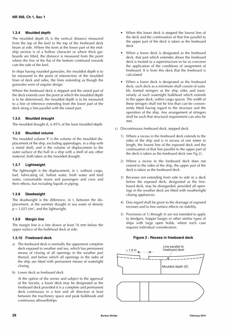
c) Discontinuous freeboard deck, stepped deck
1) Where a recess in the freeboard deck extends to thesides of the ship and is in excess of one meter inlength, the lowest line of the exposed deck and thecontinuation of that line parallel to the upper part ofthe deck is taken as the freeboard deck (see Fig 2).
2) Where a recess in the freeboard deck does notextend to the sides of the ship, the upper part of thedeck is taken as the freeboard deck.
3) Recesses not extending from side to side in a deckbelow the exposed deck, designated as the free-board deck, may be disregarded, provided all open-ings in the weather deck are fitted with weathertightclosing appliances.
4) Due regard shall be given to the drainage of exposedrecesses and to free surface effects on stability.
5) Provisions of 1) through 4) are not intended to applyto dredgers, hopper barges or other similar types ofships with large open holds, where each caserequires individual consideration.
Figure 2 : Recess in freeboard deck
Moulded depth (D)
Line parallel tofreeboard deck> 1.0 m
ritas February 2014
NR 566, Ch 1, Sec 1
1.3.11 Bulkhead deck
The bulkhead deck in a passenger ship means the upper-most deck at any point in the subdivision length LS to whichthe main bulkheads and the ship’s shell are carried water-tight. In a cargo ship the freeboard deck may be taken as thebulkhead deck.
1.3.12 Inner deck
The inner side is the longitudinal bulkhead which limits theinner hull for ships fitted with double hull.
1.3.13 Superstructure
A superstructure is a decked structure connected to the free-board deck, extending from side to side of the ship or withthe side plating not being inboard of the shell plating morethan 0,04 B.
1.3.14 Enclosed and open superstructure
A superstructure may be:
• enclosed, where:
- it is enclosed by front, side and aft bulkheads com-plying with the hull requirements of Rules for SteelShips, Part D, Chapter 21
- all front, side and aft openings are fitted with effi-cient weathertight means of closing
• open, where it is not enclosed.
1.3.15 Bridge
A bridge is a superstructure which does not extend to eitherthe forward or after perpendicular.
1.3.16 Poop
A poop is a superstructure which extends from the after per-pendicular forward to a point which is aft of the forwardperpendicular. The poop may originate from a point aft ofthe aft perpendicular.
1.3.17 Forecastle
A forecastle is a superstructure which extends from the for-ward perpendicular aft to a point which is forward of theafter perpendicular. The forecastle may originate from apoint forward of the forward perpendicular.
1.3.18 Full superstructure
A full superstructure is a superstructure which, as a mini-mum, extends from the forward to the after perpendicular.
1.3.19 Raised quarter deck
A raised quarterdeck is a partial superstructure of reducedheight as defined in [1.3.24].
It extends forward from the after perpendicular and has anintact front bulkhead (sidescuttles of the non-opening typefitted with efficient deadlights and bolted man hole covers).
February 2014 Bureau Ve
Where the forward bulkhead is not intact due to doors andaccess openings, the superstructure is then to be consideredas a poop.
1.3.20 Superstructure deck
A superstructure deck is a deck forming the upper boundaryof a superstructure.
1.3.21 Deckhouse
A deckhouse is a decked structure other than a superstruc-ture, located on the freeboard deck or above.
1.3.22 Trunk
A trunk is a decked structure similar to a deckhouse, but notprovided with a lower deck.
1.3.23 Well
A well is any area on the deck exposed to the weather,where water may be entrapped. Wells are considered to bedeck areas bounded on two or more sides by deck struc-tures.
1.3.24 Standard height of superstructure
The standard height of superstructure is defined in Tab 1.
Table 1 : Standard height of superstructure
1.3.25 Type A ship
A Type A ship is one which:
• is designed to carry only liquid cargoes in bulk
• has a high integrity of the exposed deck with only smallaccess openings to cargo compartments, closed bywatertight gasketed covers of steel or equivalent mate-rial; and
• has low permeability of loaded cargo compartments.
A Type A ship is to be assigned a freeboard following therequirements reported in the International Load Line Con-vention 1966, as amended.
1.3.26 Type B ship
All ships which do not come within the provisions regard-ing Type A ships stated in [1.3.25] are to be considered asType B ships.
A Type B ship is to be assigned a freeboard following therequirements reported in the International Load Line Con-vention 1966, as amended.
Load line length LLL,
in m
Standard height hS, in m
Raised quarterdeck
All othersuperstructures
LLL ≤ 30 0,90 1,80
30 < LLL < 75 0,9 + 0,00667 (LLL − 30) 1,80
75 ≤ LLL < 125 1,2 + 0,012 (LLL − 75) 1,8 + 0,01 (LLL − 75)
LLL ≥ 125 1,80 2,30
ritas 27

NR 566, Ch 1, Sec 1
1.3.27 Position 1Position 1 includes:
• exposed freeboard and raised quarter decks
• exposed superstructure decks situated forward of0,25 LLL from the perpendicular, at the forward side ofthe stem, to the waterline at 85% of the least mouldeddepth measured from the top of the keel.
1.3.28 Position 2Position 2 includes:
• exposed superstructure decks situated aft of 0,25 LLL
from the perpendicular, at the forward side of the stem,to the waterline at 85% of the least moulded depthmeasured from the top of the keel and located at leastone standard height of superstructure above the free-board deck,
• exposed superstructure decks situated forward of0,25 LLL from the perpendicular, at the forward side ofthe stem, to the waterline at 85% of the least mouldeddepth measured from the top of the keel and located atleast two standard heights of superstructure above thefreeboard deck.
28 Bureau Ve
1.3.29 ScuppersScuppers are piping systems for evacuation from or drainingof open spaces situated above the freeboard deck. Thisincludes the following arrangements:• draining of exposed decks• draining of open superstructures• gravity sanitary evacuation from open superstructures.
1.3.30 Pipe dischargesPipe discharges are piping systems for pump overboard dis-charges from spaces situated below the freeboard deck andevacuation from or draining of enclosed spaces situatedabove the freeboard deck. This includes the followingarrangements:• overboard discharges of pumps situated under the free-
board deck• draining of enclosed superstructures• gravity sanitary evacuation from enclosed superstruc-
tures.
1.3.31 Inboard endThe inboard end of discharge piping is the open end of thepipe situated inside the ship opposite to the end where thedischarge is led through the hull.
ritas February 2014

NR 566, Ch 1, Sec 2
SECTION 2 GENERAL ARRANGEMENT DESIGN
1 Subdivision arrangement
1.1 Number of watertight bulkheads
1.1.1 General
All ships are to have at least the following transverse water-tight bulkheads:
• one collision bulkhead
• one after peak bulkhead for passenger ships, ro-ro pas-senger ships and crew boats
• two bulkheads forming the boundaries of the machineryspace in ships with machinery amidships, and a bulk-head forward of the machinery space in ships withmachinery aft. In the case of ships with an electricalpropulsion plant, both the generator room and theengine room are to be enclosed by watertight bulk-heads.
Additional bulkheads may be required for ships having tocomply with subdivision or damage stability criteria.
1.2 Collision bulkhead
1.2.1 A collision bulkhead is to be fitted which is to bewatertight up to the bulkhead deck. This bulkhead is to belocated at a distance from the forward perpendicular of notless than 0,05 LLL and, except as may be permitted by theSociety, not more than (0,05 LLL + 3) m or 5,5 m, whicheveris the greater.
1.2.2 Where any part of the ship below the waterlineextends forward of the forward perpendicular, e.g. a bul-bous bow, the distances, in metres, stipulated in [1.2.1] areto be measured from a point either:
• at the midlength of such extension, or
• at a distance 1,5% of the length LLL of the ship forwardof the forward perpendicular, or
• at a distance 3 m forward of the forward perpendicular;whichever gives the smallest measurement.
1.2.3 The bulkhead may have steps or recesses providedthey are within the limits prescribed in [1.2.1] and [1.2.2].
1.2.4 At Owner request, the Society may, on a case by casebasis, accept a distance from the collision bulkhead to theforward perpendicular FPLL greater than the maximum spec-ified in [1.2.1] and [1.2.2], provided that subdivision andstability calculations show that, when the ship is in uprightcondition on full load summer waterline, flooding of thespace forward of the collision bulkhead will not result inany part of the freeboard deck becoming submerged, or inany unacceptable loss of stability.
February 2014 Bureau Ve
1.2.5 Where bow doors are fitted and a sloping loadingramp forms part of the extension of the collision bulkheadabove the freeboard deck, the part of the ramp which ismore than 2,3 m above the freeboard deck may extend for-ward of the limit specified in [1.2.1] and [1.2.2] The ramp isto be weathertight over its complete length.
1.3 Height of transverse watertight bulkheads
1.3.1 Transverse watertight bulkheads are to extend water-tight up to the bulkhead deck.
1.3.2 Where it is not practicable to arrange a watertightbulkhead in one plane, a stepped bulkhead may be fitted. Inthis case, the part of the deck which forms the step is to bewatertight and equivalent in strength to the bulkhead.
1.4 Openings in watertight bulkheads and decks
1.4.1 Application
a) Requirements from [1.4.2] to [1.4.6] and [1.4.9] applyto all ships
b) Requirement [1.4.7] applies to passenger ships ofLLL > 24 m or carrying more than 200 passengers
c) Requirement [1.4.8] applies to ships other than passen-ger ships of LLL > 24 m or carrying more than 200 pas-sengers.
1.4.2 Definitions
Openings “used while at sea” are openings which areallowed to remain open during navigation.
Openings “normally closed at sea” are openings which arenot allowed to be remained open but can be used duringnavigation. These openings are considered to be immedi-ately closed after use.
Openings “permanently kept closed at sea” are openingswhich remain closed and are not used during navigation.
1.4.3 The number of openings in watertight subdivisions isto be kept to a minimum compatible with the design andproper working of the ship. Where penetration of watertightbulkheads and internal decks are necessary for access, pip-ing, ventilation, electrical cables, etc., arrangements are tobe made to maintain the watertight integrity.
1.4.4 No door, manhole, ventilation duct or any otheropening is permitted in the collision bulkhead below thesubdivision deck.
ritas 29

NR 566, Ch 1, Sec 2
Table 1 : Doors
Sliding type Hinged type
Remote operation indication on the
bridge
Indicator on the bridge
Local operation
only
Remote operation indication on the
bridge
Indicator on the bridge
Local operation
only
Watertight
Open at sea X
Normally closed (1) X (4) X (5) X
Remain closed (1) X (2) (3) X (2) (3)
(1) Notice to be affixed on both sides of the door: “to be kept closed at sea”.(2) The door is to be closed before the voyage commences.(3) If the door is accessible during the voyage, a device which prevents unauthorised opening is to be fitted.(4) For passenger ships of LLL > 24 m or carrying more than 200 passengers.(5) For ships other than passenger ships of LLL > 24 m or carrying more than 200 passengers.
1.4.5 The requirements relevant to the degree of tightness,as well as the operating systems, for doors or other closingappliances complying with the provisions in [1.4.6] to[1.4.9], are specified in Tab 1.
1.4.6 Openings used while at sea
Doors provided to ensure the watertight integrity of internalopenings which are used while at sea are to be slidingwatertight doors capable of being remotely closed from thebridge and are also to be operable locally from each side ofthe bulkhead. Indicators are to be provided at the controlposition showing whether the doors are open or closed, andan audible alarm is to be provided at the door closure. Thepower, control and indicators are to be operable in theevent of main power failure. Particular attention is to bepaid to minimise the effect of control system failure. Eachpower-operated sliding watertight door is to be providedwith an individual hand-operated mechanism.
1.4.7 Openings normally closed at sea for passenger ships of LLL > 24 m or carrying more than 200 passengers
Doors provided to ensure the watertight integrity of internalopenings which are normally closed at sea are to be slidingwatertight doors capable of being remotely closed from thebridge and are also to be operable locally from each side ofthe bulkhead. Indicators are to be provided at the controlposition showing whether the doors are open or closed, andan audible alarm is to be provided at the door closure. Thepower, control and indicators are to be operable in theevent of main power failure. Particular attention is to bepaid to minimise the effect of control system failure. Eachpower-operated sliding watertight door is to be providedwith an individual hand-operated mechanism.
1.4.8 Openings normally closed at sea for ships other than passenger ships of LLL > 24 m or carrying more than 200 passengers
Doors provided to ensure the watertight integrity of internalopenings which are normally closed at sea are to be pro-vided with means of indication locally and on the bridge
30 Bureau Ve
showing whether these doors are open or closed. A noticeis to be affixed to each such door or hatch cover to theeffect that it is not to be left open.
1.4.9 Openings permanently kept closed at sea
Doors provided to ensure the watertight integrity of internalopenings which are kept permanently closed at sea are tobe provided with a notice which is to be affixed to eachsuch closing appliance to the effect that it is to be keptclosed. Manholes fitted with closely bolted covers need notbe so marked.
2 Compartment arrangement
2.1 Cofferdams
2.1.1 Definition
A cofferdam means an empty space arranged so that com-partments on each side have no common boundary; a cof-ferdam may be located vertically or horizontally. As a rule,a cofferdam is to be properly ventilated and of sufficientsize to allow for inspection.
2.1.2 Cofferdams are to be provided between:
• compartments intended for liquid hydrocarbons (fueloil, lubricating oil) and compartments intended for freshwater (drinking water, water for propelling machineryand boilers)
• compartments intended for liquid hydrocarbons (fueloil, lubricating oil) and tanks intended for the carriage ofliquid foam for fire extinguishing.
2.1.3 Spaces intended for the carriage of highly flammableliquids (flash point less than 60°C) are to be separated fromaccommodation and service spaces by means of a coffer-dam. Where accommodation and service spaces arearranged immediately above such spaces, the cofferdammay be omitted only where the deck is not provided withaccess openings and is coated with a layer of material rec-ognized as suitable by the Society.
ritas February 2014
NR 566, Ch 1, Sec 2
2.2 Double bottoms
2.2.1 Double bottom for ships other than tankers
If fitted, double bottoms are to be in accordance with theapplicable requirements of the Rules for Steel Ships, Part B.
2.2.2 Double bottom for tankers
Special requirements for tankers are specified in the Rulesfor Steel Ships, Part D, Chapter 7.
2.3 Compartments forward of the collision bulkhead
2.3.1 The fore peak and other compartments located for-ward of the collision bulkhead cannot be used for the car-riage of fuel oil or other flammable products.
This requirement does not apply to ships of less than400 tons gross tonnage, except for those where the forepeak is the forward cofferdam of tanks arranged for the car-riage of flammable liquid products having a flash point notexceeding 60°C.
2.4 Shaft tunnels
2.4.1 Shaft tunnels are to be watertight.
3 Access arrangement
3.1 General
3.1.1 The number and size of small hatchways for trimmingand access openings to tanks or other enclosed spaces, areto be kept to the minimum consistent with access and main-tenance of the space.
3.2 Double bottoms
3.2.1 If fitted, access details to and inside double bottomsare to be in accordance with the applicable requirements ofthe Rules for Steel Ships, Part B.
3.2.2 Tanks with a length equal to or greater than 35 m
Tanks and subdivisions of tanks having lengths of 35 m andabove are to be fitted with at least two access hatchwaysand ladders, as far apart as practicable longitudinally.
3.2.3 Tanks with a length less than 35 m
Tanks less than 35 m in length are to be served by at leastone access hatchway and ladder.
3.2.4 Dimensions of access hatchways
The dimensions of any access hatchway are to be sufficientto allow a person wearing a self-contained breathing appa-ratus to ascend or descend the ladder without obstructionand also to provide a clear opening to facilitate the hoistingof an injured person from the bottom of the tank. In no caseis the clear opening to be less than 600 mm x 600 mm.
February 2014 Bureau Ve
3.2.5 Tanks subdivided by wash bulkheadsWhen a tank is subdivided by one or more wash bulkheads,at least two hatchways are to be fitted, and these hatchwaysare to be so located that the associated ladders effectivelyserve all subdivisions of the tank.
3.2.6 Wash bulkheads in tanksWhere one or more wash bulkheads are fitted in a tank,they are to be provided with openings not less than600 mm x 800 mm and so arranged as to facilitate theaccess of persons wearing breathing apparatus or carrying astretcher with a patient.
3.2.7 Passage on the tank bottomTo provide ease of movement on the tank bottom through-out the length and breadth of the tank, a passageway is tobe fitted on the upper part of the bottom structure of eachtank, or alternatively, manholes having at least the dimen-sions of 600 mm x 800 mm are to be arranged in the floorsat a height of not more than 600 mm from the bottom shellplating.
3.2.8 Passageways in the tanks
a) Passageways in the tanks are to have a minimum widthof 600 mm considering the requirement for the possibil-ity of carrying an unconscious person. Elevated passage-ways are to be provided with guard rails over their entirelength. Where guard rails are provided on one side only,foot rails are to be fitted on the opposite side. Shelvesand platforms forming a part of the access to the tanksare to be of non-skid construction where practicableand be fitted with guard rails. Guard rails are to be fittedto bulkhead and side stringers when such structures arebeing used for recognised access.
b) Access to elevated passageways from the ship's bottomis to be provided by means of easily accessible passage-ways, ladders or treads. Treads are to provide lateralsupport for the foot. Where rungs of ladders are fittedagainst a vertical surface, the distance from the centre ofthe rungs to that surface is to be at least 150 mm.
c) When the height of the bottom structure does notexceed 1,50 m, the passageways required in a) may bereplaced by alternative arrangements having regard tothe bottom structure and requirement for ease of accessof a person wearing a self-contained breathing appara-tus or carrying a stretcher with a patient.
3.2.9 ManholesWhere manholes are fitted, access is to be facilitated bymeans of steps and hand grips with platform landings oneach side.
3.2.10 Guard railsGuard rails are to be 900 mm in height and consist of a railand intermediate bar. These guard rails are to be of substan-tial construction.
3.2.11 GeneralIn general, the ladders are not to be inclined at an angleexceeding 70°. The flights of ladders are not to be morethan 9 m in actual length. Resting platforms of adequatedimensions are to be provided.
ritas 31

NR 566, Ch 1, Sec 2
3.2.12 Construction
Ladders and handrails are to be constructed of steel of ade-quate strength and stiffness and securely attached to thetank structure by stays. The method of support and length ofstay are to be such that vibration is reduced to a practicalminimum.
3.2.13 Corrosive effect of the cargo
Provision is to be made for maintaining the structuralstrength of the ladders and railings taking into account thecorrosive effect of the cargo.
3.2.14 Width of ladders
The width of ladders between stringers is not to be less than400 mm.
3.2.15 Treads
The treads are to be equally spaced at a distance apartmeasured vertically not exceeding 300 mm. They are to beformed of two square steel bars of not less than 22 mm by22 mm in section fitted to form a horizontal step with theedges pointing upward, or of equivalent construction. Thetreads are to be carried through the side stringers andattached thereto by double continuous welding.
3.2.16 Sloping ladders
All sloping ladders are to be provided with handrails of sub-stantial construction on both sides fitted at a convenient dis-tance above the treads.
3.2.17 Access to the tunnel is to be provided by a water-tight door fitted on the aft bulkhead of the engine room incompliance with [1.4], and an escape trunk which can alsoact as watertight ventilator is to be fitted up to the subdivi-sion deck, for tunnels greater than 7 m in length.
3.2.18 Tunnels are to be large enough to ensure easyaccess to shafting.
32 Bureau Ve
3.2.19 The steering gear compartment is to be readilyaccessible and, as far as practicable, separated frommachinery spaces.
3.2.20 Suitable arrangements to ensure working access tosteering gear machinery and controls are to be provided.These arrangements are to include handrails and gratings orother non-slip surfaces to ensure suitable working condi-tions in the event of hydraulic fluid leakage.
4 Helicopter facilities
4.1 General
4.1.1 The applicable rules of the relevant chapters of theRules for Steel Ships are to be complied with in case of thepresence of helicopter facilities on board.
5 Accommodation
5.1 Seating of crew boats
5.1.1 For ships with service notation crew boat, a seat is toprovided for each personnel being carried and each crewfor which the ship is certified to carry. Such seats are to bearranged in enclosed spaces.
6 Crew protection
6.1 Bulwarks and guard rails
6.1.1 Bulwarks and guard rails arrangements are to be inaccordance with the provisions of the Rules for Steel Ships,Pt B, Ch 10, Sec 2.
6.1.2 For ships with specific operations at sea (Pilot boat forexample), alternative arrangements such as safety harnessesand jack-stays may be accepted if they provide an equiva-lent level of safety.
ritas February 2014
NR 566, Ch 1, Sec 3
SECTION 3 STABILITY
1 General
1.1 Application
1.1.1 Intact stability
Every ship is to comply with the provisions of Article [2],regarding intact stability.
1.1.2 Damage stability
The following ships are to comply with Article [3] regardingdamage stability:
• Passenger ships of LLL > 24 m or carrying more than
200 passengers
• Crew boats for which the additional class notation SDShas been requested.
Note 1: For other ships, the applicable requirements for the addi-tional class notation SDS will be defined on a case-by-case basis.
1.2 Relaxation
1.2.1 Relaxation in the requirements of Article [3] could beaccepted for ships with navigation notation sheltered area.
2 Intact stability
2.1 Requirements
2.1.1 The intact stability is to comply with the provisions ofthe Rules for Steel Ships, Part B, Chapter 3.
2.1.2 Additional criteria could be required for specific serv-ice notations as per the Rules for Steel Ships, Part D.
3 Damage stability
3.1 General
3.1.1 Taking into account, as initial conditions beforeflooding, the standard loading conditions as referred to inthe Rules for Steel Ships, Part B, Chapter 3, the ship is tocomply with the damage stability criteria as specified in[3.7].
3.2 Damage dimensions
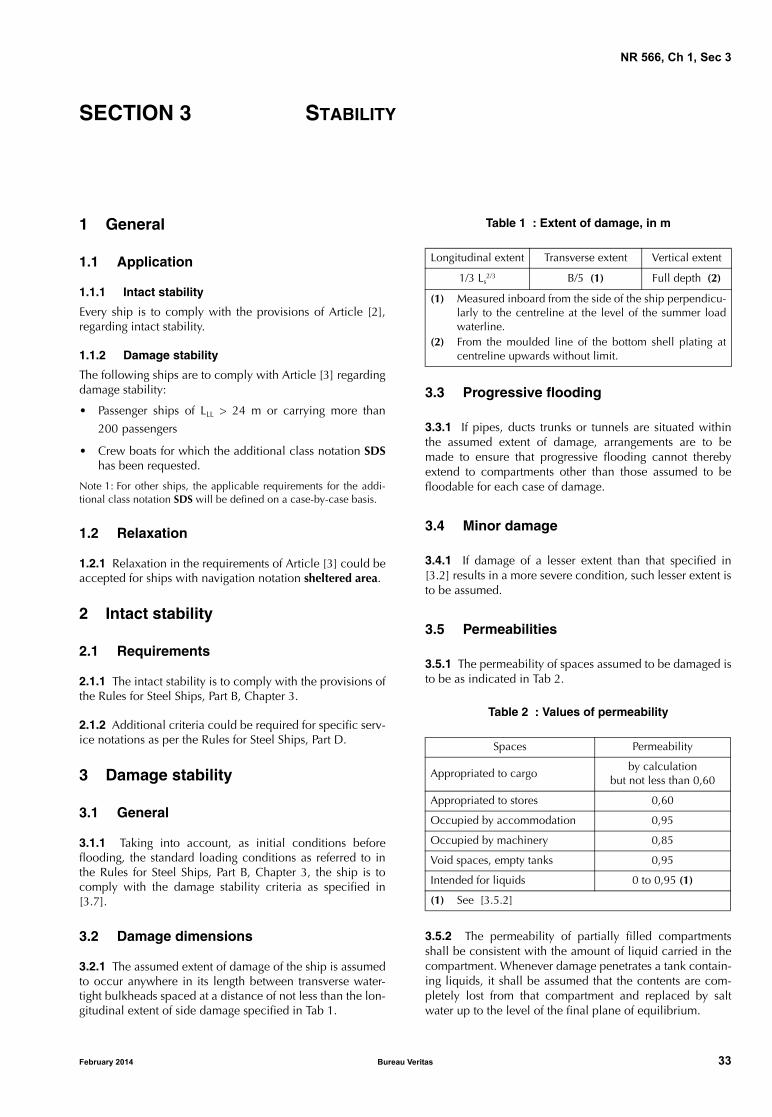
3.2.1 The assumed extent of damage of the ship is assumedto occur anywhere in its length between transverse water-tight bulkheads spaced at a distance of not less than the lon-gitudinal extent of side damage specified in Tab 1.
February 2014 Bureau Ve
Table 1 : Extent of damage, in m
3.3 Progressive flooding
3.3.1 If pipes, ducts trunks or tunnels are situated withinthe assumed extent of damage, arrangements are to bemade to ensure that progressive flooding cannot therebyextend to compartments other than those assumed to befloodable for each case of damage.
3.4 Minor damage
3.4.1 If damage of a lesser extent than that specified in[3.2] results in a more severe condition, such lesser extent isto be assumed.
3.5 Permeabilities
3.5.1 The permeability of spaces assumed to be damaged isto be as indicated in Tab 2.
Table 2 : Values of permeability
3.5.2 The permeability of partially filled compartmentsshall be consistent with the amount of liquid carried in thecompartment. Whenever damage penetrates a tank contain-ing liquids, it shall be assumed that the contents are com-pletely lost from that compartment and replaced by saltwater up to the level of the final plane of equilibrium.
Longitudinal extent Transverse extent Vertical extent
1/3 Ls2/3 B/5 (1) Full depth (2)
(1) Measured inboard from the side of the ship perpendicu-larly to the centreline at the level of the summer loadwaterline.
(2) From the moulded line of the bottom shell plating atcentreline upwards without limit.
Spaces Permeability
Appropriated to cargoby calculation
but not less than 0,60
Appropriated to stores 0,60
Occupied by accommodation 0,95
Occupied by machinery 0,85
Void spaces, empty tanks 0,95
Intended for liquids 0 to 0,95 (1)
(1) See [3.5.2]
ritas 33
NR 566, Ch 1, Sec 3
3.6 Survival requirements
3.6.1 Compliance with the requirements of [3.7] is to beconfirmed by calculations which take into consideration thedesign characteristics of the ship, the arrangements, config-uration and permeability of the damaged compartmentsand the distribution, specific gravities and free surface effectof liquids.
3.7 Damage stability criteria
3.7.1 The final waterline, taking into account sinkage, heeland trim, is to be below the lower edge of any openingthrough which progressive flooding may take place. Suchopenings include air-pipes, ventilators and openings whichare closed by means of weathertight doors or hatch coversbut may exclude those openings closed by means of water-tight manhole covers and flush scuttles, small watertightcargo tank hatch covers which maintain the high integrity ofthe deck, remotely operated watertight sliding doors andsidescuttles of the non-opening type.
In no case shall the margin line be submerged in the finalstage of flooding for passenger ships.
3.7.2 In the final stage of flooding, the angle of heel due tounsymmetrical flooding may not exceed 7°. In the case offlooding involving the collision bulkhead the angle of heeldue to unsymmetrical flooding may not exceed 12°. In spe-cial cases, additional heel maybe allowed but in no caseshould the final heel exceed 15°. Unsymmetrical floodingsare to be kept to the minimum. The means adopted forequalization should, when practicable, be self-acting. Inany case where controls to cross-flooding fittings are pro-vided they should be operable from above the bulkheaddeck. The fittings and the controls are to be submitted to theSociety for approval.
3.7.3 The initial metacentric height of the ship in the finalstage of flooding for the static equilibrium position in caseof symmetrical flooding and for the upright position in caseof unsymmetrical flooding as calculated by constant dis-placement method should not be less than 0,05 m beforeappropriate measures to increase the metacentric heighthave been taken.
3.7.4 The righting lever curve at the final stage of floodingshould have a minimum range of at least 20° beyond theposition of equilibrium in association with a maximumresidual righting lever of at least 100 mm within this range.Unprotected openings may not become immersed at anangle of heel within the prescribed minimum range of resid-ual stability unless the space in question has been includedas a floodable space in calculations for damage stability.Within this range, immersion of any of the openingsreferred to in [3.7.1], and any other openings capable ofbeing closed weathertight may be authorised.
For passenger ships, a residual righting lever is to beobtained within the range of positive stability taking intoaccount the greatest of the heeling moments as defined in[3.8], as calculated by the formula:
34 Bureau Ve
However in no case this righting lever is to be less than0,1 m.
3.7.5 The stability is to be sufficient during the intermediatestages of flooding. In this regard the Society applies thesame criteria relevant to the final stage of flooding also dur-ing the intermediate stages of flooding.
3.8 Heeling moments
3.8.1 For the purpose of [3.7.4], the following heelingmoments are to be considered:
a) Moment due to the crowding of passengers
The heeling moment is to be calculated assuming thepassengers are distributed with 4 persons per squaremetre on available deck areas towards one side of theship on the decks where muster stations are located andin such a way that they produce the most adverse heel-ing moment. In doing so, a weight of 75 kg per passen-ger is to be assumed
b) Moment due to launching of all fully loaded davit-launched survival craft on one side
MSurvivalcraft is the maximum assumed heeling momentdue to the launching of all fully loaded davit-launchedsurvival craft on one side of the ship. It shall be calcu-lated using the following assumptions:
• all lifeboats and rescue boats fitted on the side towhich the ship has heeled after having sustaineddamage are to be assumed to be swung out fullyloaded and ready for lowering
• for lifeboats which are arranged to be launched fullyloaded from the stowed position, the maximumheeling moment during launching is to be taken
• a fully loaded davit-launched liferaft attached toeach davit on the side to which the ship has heeledafter having sustained damage is to be assumed tobe swung out ready for lowering
• persons not in the life-saving appliances which areswung out are not to provide either additional heel-ing or righting moment
• life-saving appliances on the side of the ship oppo-site to the side to which the ship has heeled are tobe assumed to be in a stowed position
c) Moment due to wind pressure
Mwind is the maximum assumed wind heeling moment,in t⋅m, acting in a damage situation:
Mwind = P ⋅ A ⋅ Z / (9,806 ⋅ 103)
P : Wind pressure, in N/m2, equal to:
P = 120 N/m2
A : Projected lateral area above waterline, in m2
Z : Distance, in m, from centre of lateral pro-jected area above waterline to one half ofthe mean draught corresponding to theintact condition.
GZ (in metres) heeling momentdisplacement------------------------------------------ 0 04,+=
ritas February 2014

NR 566, Ch 1, Sec 4
SECTION 4 HULL INTEGRITY
1 General
1.1 Application
1.1.1 This Section concerns the protection for intake ofwater for all openings in hull and superstructures.
1.1.2 Alternative arrangements for ships with restrictednavigation or for ships LLL < 24 m may be agreed on a case-by-case basis.
2 External openings
2.1 General
2.1.1 All external openings leading to compartmentsassumed intact in the damage analysis, which are below thefinal damage waterline, are required to be watertight.
2.1.2 External openings required to be watertight inaccordance with [2.1.1] are to be of sufficient strength and,except for cargo hatch covers, are to be fitted with indica-tors on the bridge.
2.1.3 Other closing appliances which are kept permanentlyclosed at sea to ensure the watertight integrity of externalopenings are to be provided with a notice affixed to eachappliance to the effect that it is to be kept closed. Manholesfitted with closely bolted covers need not be so marked.
2.2 Bow doors, inner doors, side doors and stern doors
2.2.1 Bow doors and inner doorsBow doors and inner doors are to comply with the provi-sions of the Rules for Steel Ships, Pt B, Ch 9, Sec 5.
2.2.2 Side doors and inner doorsSide doors and stern doors are to comply with the provi-sions of the Rules for Steel Ships, Pt B, Ch 9, Sec 6.
3 Sidescuttles, windows and skylights
3.1 General
3.1.1 ApplicationThe present Article [3] apply to sidescuttles and rectangularwindows providing light and air, located in positions whichare exposed to the action of sea and/or bad weather.
3.1.2 Sidescuttle definitionSidescuttles are round or oval openings with an area notexceeding 0,16 m2. Round or oval openings having areasexceeding 0,16 m2 are to be treated as windows.
February 2014 Bureau Ve
3.1.3 Window definitionWindows are rectangular openings generally, having aradius at each corner relative to the window size in accord-ance with recognised national or international standards,and round or oval openings with an area exceeding0,16 m2.
3.1.4 Number of openings in the shell platingThe number of openings in the shell plating are to bereduced to the minimum compatible with the design andproper working of the ship.
3.1.5 Material and scantlingsSidescuttles and windows together with their glasses, dead-lights and storm covers, if fitted, are to be of approved designand substantial construction in accordance with, or equiva-lent to, recognised national or international standards.
3.1.6 Means of closing and openingThe arrangement and efficiency of the means for closingany opening in the shell plating are to be consistent with itsintended purpose and the position in which it is fitted is tobe generally to the satisfaction of the Society.
3.1.7 Opening of sidescuttlesAll sidescuttles, the sills of which are below the bulkheaddeck for passenger ships or the freeboard deck for cargoships, are to be of such construction as to prevent effectivelyany person opening them without the consent of the Masterof the ship.
3.2 Opening arrangement
3.2.1 GeneralSidescuttles are not to be fitted in such a position that theirsills are below a line drawn parallel to the freeboard deck atside and having its lowest point 0,025B or 0,5 m, whicheveris the greater distance, above the summer load waterline (ortimber summer load waterline if assigned).
3.2.2 Cargo spacesNo sidescuttles may be fitted in any spaces which areappropriated exclusively for the carriage of cargo or coal.
Sidescuttles may, however, be fitted in spaces appropriatedalternatively for the carriage of cargo or passengers, butthey are to be of such construction as to prevent effectivelyany person opening them or their deadlights without theconsent of the Master.
3.2.3 Non-opening type sidescuttlesIf the required damage stability calculations indicate thatthe side scuttles would become immersed at any intermedi-ate stage of flooding or the final equilibrium waterline, theyshall be of the non-opening type.
ritas 35
NR 566, Ch 1, Sec 4
3.2.4 Ships with several decksIn ships having several decks above the bulkhead deck,such as passenger ships, the arrangement of sidescuttles andrectangular windows is considered by the Society on acase-by-case basis.
Particular consideration is to be given to the ship side up tothe upper deck and the front bulkhead of the superstructure.
3.2.5 Window arrangementWindows may not be fitted below the freeboard deck, infirst tier end bulkheads or sides of enclosed superstructuresand in first tier deckhouses considered as being buoyant inthe stability calculations or protecting openings leadingbelow.
For ships with restricted navigation, windows could beaccepted in first tier end bulkheads or sides of enclosedsuperstructures and in first tier deckhouses.
3.2.6 SkylightsFixed or opening skylights are to have glass thickness appro-priate to their size and position as required for sidescuttlesand windows. Skylight glasses in any position are to be pro-tected from mechanical damage and, where fitted in posi-tions 1 or 2, to be provided with permanently attachedrobust deadlights or storm covers.
3.2.7 Gangway, cargo and fuelling portsGangway, cargo and fuelling ports fitted below the bulk-head deck of passenger ships and the freeboard deck ofcargo ships are to be watertight and in no case they are tobe so fitted as to have their lowest point below the summerload line.
3.3 Glasses
3.3.1 GeneralGlasses are to comply with the provisions of the Rules forSteel Ships, Pt B, Ch 9, Sec 9.
3.4 Deadlight arrangement
3.4.1 GeneralSidescuttles to the following spaces are to be fitted with effi-cient, hinged inside deadlights:
• spaces below the freeboard deck
• spaces within the first tier of enclosed superstructures
• first tier deckhouses on the freeboard deck protectingopenings leading below or considered buoyant in stabil-ity calculations.
Deadlights are to be capable of being closed and securedwatertight if fitted below the freeboard deck and weather-tight if fitted above.
3.4.2 Openings at the side shell in the second tierSidescuttles and windows at the side shell in the secondtier, protecting direct access below or considered buoyantin the stability calculations, are to be provided with effi-cient, hinged inside deadlights capable of being effectivelyclosed and secured weathertight.
36 Bureau Ve
3.4.3 Openings set inboard in the second tierSidescuttles and windows set inboard from the side shell inthe second tier, protecting direct access below to spaceslisted in [3.4.1], are to be provided with either efficient,hinged inside deadlights or, where they are accessible, per-manently attached external storm covers of approveddesign and substantial construction capable of being effec-tively closed and secured weathertight.
Cabin bulkheads and doors in the second tier separatingsidescuttles and windows from a direct access leadingbelow may be accepted in place of fitted deadlights orstorm covers.
Note 1: Deadlights in accordance with recognised standards arefitted to the inside of windows and sidescuttles, while storm coversof comparable specifications to deadlights are fitted to the outsideof windows, where accessible, and may be hinged or portable.
3.4.4 Windows in the first tier When accepted in accordance with [3.2.5], the deadlightarrangement for these windows is to comply with the provi-sions of [3.4.2] and [3.4.3].
3.4.5 Deckhouses on superstructures of less than standard height
Deckhouses situated on a raised quarterdeck or on a super-structure of less than standard height may be treated asbeing on the second tier as far as the provision of deadlightsis concerned, provided the height of the raised quarterdeckor superstructure is not less than the standard quarterdeckheight.
4 Discharges
4.1 Arrangement of discharges
4.1.1 Inlets and dischargesAll inlets and discharges in the shell plating are to be fittedwith efficient and accessible arrangements for preventingthe accidental admission of water into the ship.
4.1.2 Inboard opening of ash-chute, rubbish-chute, etc.
The inboard opening of each ash-chute, rubbish-chute, etc.is to be fitted with an efficient cover.
If the inboard opening is situated below the bulkhead deckfor passenger ships or the freeboard deck for cargo ships,the cover is to be watertight, and in addition an automaticnon-return valve is to be fitted in the chute in an easilyaccessible position above the deepest subdivision summerload line. When the chute is not in use, both the cover andthe valve are to be kept closed and secured.
4.2 Arrangement of garbage chutes
4.2.1 Inboard end above the waterlineThe inboard end is to be located above the waterlineformed by an 8,5° heel, to port or starboard, at a draughtcorresponding to the assigned summer freeboard, but notless than 1000 mm above the summer load waterline.
ritas February 2014
NR 566, Ch 1, Sec 4
Where the inboard end of the garbage chute exceeds0,01 LLL above the summer load waterline, valve controlfrom the freeboard deck is not required, provided theinboard gate valve is always accessible under service condi-tions.
4.2.2 Inboard end below the waterline
Where the inboard end of a garbage chute is below the free-board deck, then:
• the inboard end hinged cover/valve is to be watertight
• the valve is to be a screw-down non-return valve fittedin an easily accessible position above the deepest subdi-vision load line
• the screw-down non-return valve is to be controlledfrom a position above the bulkhead deck and providedwith open/shut indicators. The valve control is to beclearly marked: “Keep closed when not in use”.
4.2.3 Gate valves
For garbage chutes, two gate valves controlled from theworking deck of the chute may be accepted instead of anon-return valve with a positive means of closing it from aposition above the freeboard deck. In addition, the lowergate valve is to be controlled from a position above the free-board deck. An interlock system between the two valves isto be arranged.
The distance between the two gate valves is to be adequateto allow the smooth operation of the interlock system.
4.2.4 Hinged cover and discharge flap
The upper gate valve, as required in [4.2.3], may bereplaced by a hinged weathertight cover at the inboard endof the chute together with a discharge flap which replacesthe lower gate valve.
The cover and discharge flap are to be arranged with aninterlock so that the flap cannot be operated until the hop-per cover is closed.
4.2.5 Marking of valve and hinged cover
The gate valve controls and/or hinged cover are to beclearly marked: “Keep closed when not in use”.
4.3 Scantlings of garbage chutes
4.3.1 Material
The chute is to be constructed of steel. Other equivalentmaterials are considered by the Society on a case-by-casebasis.
4.3.2 Wall thickness
The wall thickness of the chute up to and including thecover is to be of extra reinforced wall thickness in accord-ance wit Ch 2, Sec 4, [2].
February 2014 Bureau Ve
4.4 Scuppers
4.4.1 General
The definition of scuppers is given in Sec 1, [1.3.29].
Scuppers are to be led overboard. Exception is made forsanitary gravity evacuation systems which can be led tosuitable sanitary tanks.
4.4.2 Normal arrangement
Scupper pipes originating at any level and led through thehull below the freeboard deck are to be provided with anon-return valve at the hull. This valve may be omitted ifone of the following conditions is fulfilled:
• the end connection with the hull is situated at less than450 mm below the freeboard deck and more than600 mm above the summer load water line
• the part of the scupper piping below the freeboard deckis of extra reinforced thickness in accordance with Ch 2,Sec 4, [2].
4.5 Pipe discharges
4.5.1 General
The definition of pipe discharges is given in Sec 1, [1.3.30].
Pipe discharges can be led overboard or led to the bilge. Incase of sanitary gravity evacuation systems, they are to beled either overboard or to suitable sanitary tanks.
4.5.2 Normal arrangement
Each separate pipe discharge led through the shell plating isto be provided with:
• an automatic non-return valve fitted with a positivemeans of closing from a position above the freeboarddeck
• an automatic non-return valve and one closing valvecontrolled from above the freeboard deck.
4.5.3 Alternative arrangement when the inboard end of the discharge pipe is above the summer waterline by more than 0,01 LLL
Where the vertical distance from the summer load waterlineto the inboard end of the discharge pipe exceeds 0,01 LLL ,the discharge pipe may have two automatic non-returnvalves without positive means of closing, provided that:
• the inboard valve is above the level of the tropical loadwaterline so as to always be accessible for examinationunder service conditions, or
• where this is not practicable, a locally controlled clos-ing valve is interposed between the two automatic non-return valves.
4.5.4 Alternative arrangement when the inboard end of the discharge pipe is above the summer waterline by more than 0,02 LLL
Where the vertical distance from the summer load waterlineto the inboard end of the discharge pipe exceeds 0,02 LLL ,the discharge pipe may have a single automatic non-returnvalve without positive means of closing.
ritas 37
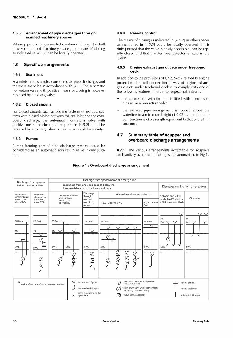
NR 566, Ch 1, Sec 4
4.5.5 Arrangement of pipe discharges through manned machinery spaces
Where pipe discharges are led overboard through the hullin way of manned machinery spaces, the means of closingas indicated in [4.5.2] can be locally operated.
4.6 Specific arrangements
4.6.1 Sea inlets
Sea inlets are, as a rule, considered as pipe discharges andtherefore are to be in accordance with [4.5]. The automaticnon-return valve with positive means of closing is howeverreplaced by a closing valve.
4.6.2 Closed circuits
For closed circuits such as cooling systems or exhaust sys-tems with closed piping between the sea inlet and the over-board discharge, the automatic non-return valve withpositive means of closing as required in [4.5.2] could bereplaced by a closing valve to the discretion of the Society.
4.6.3 Pumps
Pumps forming part of pipe discharge systems could beconsidered as an automatic non return valve if duly justi-fied.
38 Bureau Ve
4.6.4 Remote control
The means of closing as indicated in [4.5.2] in other spacesas mentioned in [4.5.5] could be locally operated if it isduly justified that the valve is easily accessible, can be rap-idly closed and that a water level detector is fitted in thespace.
4.6.5 Engine exhaust gas outlets under freeboard deck
In addition to the provisions of Ch 2, Sec 7 related to engineprotection, the hull connection in way of engine exhaustgas outlets under freeboard deck is to comply with one ofthe following features, in order to respect hull integrity:
• the connection with the hull is fitted with a means ofclosure or a non-return valve
• the exhaust pipe arrangement is looped above thewaterline to a minimum height of 0,02 LLL and the pipeconstruction is of a strength equivalent to that of the hullstructure.
4.7 Summary table of scupper and overboard discharge arrangements
4.7.1 The various arrangements acceptable for scuppersand sanitary overboard discharges are summarised in Fig 1.
Figure 1 : Overboard discharge arrangement
Discharge from spacesbelow the margin line
Discharge from spaces above the margin line
Discharge coming from other spacesDischarge from enclosed spaces below the freeboard deck or on the freeboard deck
General req. where inboard end < 0,01Labove SWL
General requirement where inboard end < 0,01Labove SWL
Alternativewhere inboard end > 0,01Labove SWL
FB Deck
ML
SWL
FB Deck
ML
SWL
FB Deck
SWL
FB Deck
ML
SWL
DWL
SWL
FB Deck FB Deck
SWL SWL
FB Deck
SWL
FB Deck
SWL
Discharge through manned machinery spaces
Alternatives where inboard end:
>0,01L above SWL >0,02L aboveSWL
TWL
outboard end > 450 mm below FB deck or < 600 mm above SWL
Otherwise
*
control of the valves from an approved positioninboard end of pipes non return valve without positive
means of closing remote control
outboard end of pipes non return valve with positive means of closing controlled locally
normal thickness
substantial thicknesspipes terminating on theopen deck valve controlled locally
*
ritas February 2014
NR 566, Ch 1, Sec 4
5 Machinery space openings
5.1 Closing devices
5.1.1 Machinery casingsOpenings in machinery space casings in positions 1 or 2 areto be fitted with doors of steel or other equivalent materials,permanently and strongly attached to the bulkhead, andframed, stiffened and fitted so that the whole structure is ofequivalent strength to the unpierced bulkhead and weather-tight when closed. The doors are to be capable of beingoperated from both sides and generally to open outwards togive additional protection against wave impact.
Other openings in such casings are to be fitted with equiva-lent covers, permanently attached in their proper position.
5.1.2 Machinery casings on Type A shipsMachinery casings on Type A ships are to be protected byan enclosed poop or bridge of at least standard height, or bya deckhouse of equal height and equivalent strength.
Machinery casings may, however, be exposed if there areno openings giving direct access from the freeboard deck tothe machinery spaces.
However, a weathertight door is permitted in the machinerycasing, provided that it leads to a space or passagewaywhich is as strongly constructed as the casing and is sepa-rated from the stairway to the engine room by a secondweathertight door of steel or other equivalent material.
5.1.3 Height of the sill of the doorThe height of the sill of the door is to be not less than:
• 600 mm above the deck if in position 1
• 380 mm above the deck if in position 2
• 230 mm in all other cases.
For ships with restricted navigation, these values could bereduced to:
• 450 mm above the deck if in position 1
• 230 mm in all other cases.
5.1.4 Double doorsWhere casings are not protected by other structures, doubledoors (i.e. inner and outer doors) are required for shipsassigned freeboard less than that based on Table B of regu-lation 28 of the International Load Line Convention 1966,as amended. An inner sill of 230 mm in conjunction withthe outer sill of 600 mm is to be provided.
5.1.5 Fiddly openingsFiddly openings are to be fitted with strong covers of steel orother equivalent material permanently attached in theirproper positions and capable of being secured weathertight.
5.2 Coamings
5.2.1 Coamings of any fiddly, funnel or machinery spaceventilator in an exposed position on the freeboard deck orsuperstructure deck are to be as high above the deck as isreasonable and practicable.
February 2014 Bureau Ve
In general, ventilators necessary to continuously supply themachinery space and, on demand, the emergency generatorroom are to have coamings whose height is in compliancewith [8.1.2], but need not be fitted with weathertight clos-ing appliances.
Where, due to the ship’s size and arrangement, this is notpracticable, lesser heights for machinery space and emer-gency generator room ventilator coamings, fitted withweathertight closing appliances in accordance with [8.1.2],may be permitted by the Society in combination with othersuitable arrangements to ensure an uninterrupted, adequatesupply of ventilation to these spaces.
6 Companionway
6.1 General
6.1.1 Openings in freeboard deck
Openings in freeboard deck other than hatchways, machin-ery space openings, manholes and flush scuttles are to beprotected by an enclosed superstructure or by a deckhouseor companionway of equivalent strength and weathertight-ness.
6.1.2 Openings in superstructures
Openings in an exposed superstructure deck or in the top ofa deckhouse on the freeboard deck which give access to aspace below the freeboard deck or a space within anenclosed superstructure are to be protected by an efficientdeckhouse or companionway.
6.1.3 Openings in superstructures having height less than standard height
Openings in the top of a deckhouse on a raised quarterdeckor superstructure of less than standard height, having aheight equal to or greater than the standard quarterdeckheight are to be provided with an acceptable means of clos-ing but need not be protected by an efficient deckhouse orcompanionway provided the height of the deckhouse is atleast the standard height of a superstructure.
6.2 Scantlings
6.2.1 Companionways on exposed decks protecting open-ings leading into enclosed spaces are to be of steel andstrongly attached to the deck and are to have adequatescantlings.
6.3 Closing devices
6.3.1 Doors
Doorways in deckhouses or companionways leading to orgiving access to spaces below the freeboard deck or toenclosed superstructures are to be fitted with weathertightdoors. The doors are to be made of steel or other equivalentmaterials, to be capable of being operated from both sidesand generally to open outwards to give additional protec-tion against wave impact.
ritas 39

NR 566, Ch 1, Sec 4
Alternatively, if stairways within a deckhouse are enclosedwithin properly constructed companionways fitted withweathertight doors, the external door need not be water-tight.
Where the closing appliances of access openings in super-structures and deckhouses are not weathertight, interiordeck openings are to be considered exposed, i.e. situated inthe open deck.
6.3.2 Height of sills
The height above the deck of sills to the doorways in com-panionways is to be not less than:
• 600 mm in position 1
• 380 mm in position 2.
For ships with restricted navigation, these values could bereduced to:
• 380 mm in position 1
• 230 mm in all the other cases.
Where access is not provided from above, the height of thesills to doorways in a poop bridge or deckhouse on the free-board deck is to be 600 mm.
Where access is provided to spaces inside a bridge or poopfrom the deck as an alternative to access from the freeboarddeck, the height of the sills into the bridge or poop is to be380 mm. This also applies to deckhouses on the freeboarddeck.
7 Hatches
7.1 Hatchways
7.1.1 Coamings
The coamings of hatchways shall be constructed accordingto the provisions of the Rules for Steel Ships, Pt B, Ch 9, Sec7 in accordance with their position and their height shall beat least as follows:
• 600 mm if in position 1
• 450 mm if in position 2.
For ships with restricted navigation or LLL less than 24 m,these values could be reduced to:
• 450 mm in position 1
• 300 mm in position 2.
For ships with a length LLL less than 24 m, the coamingheight of hatches closed at sea may be reduced or omittedentirely, on condition that the Society is satisfied that thesafety of the ship is not thereby impaired in any sea condi-tions.
7.1.2 Hatch covers
Hatch covers are to comply with the provisions of the Rulesfor Steel Ships, Pt B, Ch 9, Sec 7.
40 Bureau Ve
7.1.3 Manholes and flush scuttles
Manholes and flush scuttles in positions 1 or 2, or withinsuperstructures other than enclosed superstructures, are tobe closed by substantial covers capable of being madewatertight. Unless secured by closely spaced bolts, the cov-ers are to be permanently attached.
8 Ventilation openings
8.1 Ventilation openings
8.1.1 General
Ventilator openings are to be provided with efficient weath-ertight closing appliances of steel or other equivalent mate-rial.
8.1.2 Closing appliance exemption
Ventilators need not be fitted with closing appliances,unless specifically required by the Society, if the coamingsextend for more than:
• 4,5 m above the deck in position 1
• 2,3 m above the deck in position 2.
The closing appliances are to be permanently attached tothe ventilator coamings.
8.1.3 Ventilation of machinery spaces and emergency generator room
In order to satisfactorily ensure, in all weather conditions:
• the continuous ventilation of machinery spaces, and,when necessary,
• the immediate ventilation of the emergency generatorroom,
the ventilators serving such spaces are to comply with[8.1.2], i.e. their openings are to be so located that they donot require closing appliances.
8.1.4 Reduced height of ventilator coamings for machinery spaces and emergency generator room
Where, due to the ship’s size and arrangement, the require-ments in [8.1.3] are not practicable, lesser heights may beaccepted for machinery space and emergency generatorroom ventilator coamings fitted with weathertight closingappliances in accordance with [8.1.1] and [8.1.2] in combi-nation with other suitable arrangements, such as separatorsfitted with drains, to ensure an uninterrupted, adequate sup-ply of ventilation to these spaces.
8.1.5 Closing arrangements of ventilators led overboard or through enclosed superstructures
Closing arrangements of ventilators led overboard to theship side or through enclosed superstructures are consid-ered by the Society on a case-by-case basis. If such ventila-tors are led overboard more than 4,5 m above the freeboarddeck, closing appliances may be omitted provided that sat-isfactory baffles and drainage arrangements are fitted.
ritas February 2014
NR 566, Ch 1, Sec 4
8.2 Coamings
8.2.1 GeneralVentilators in positions 1 or 2 to spaces below freeboarddecks or decks of enclosed superstructures are to havecoamings of steel or other equivalent material, substantiallyconstructed and efficiently connected to the deck.
Ventilators passing through superstructures other thanenclosed superstructures are to have substantially con-structed coamings of steel or other equivalent material atthe freeboard deck.
8.2.2 Coaming heightVentilators shall have coamings of a height above the deckof at least:
• 900 mm in position 1
• 760 mm in position 2.
For ships with restricted navigation or LLL less than 24 m,these values could be reduced to:
• 760 mm in position 1
• 380 mm in position 2.
Where the coaming of any ventilator exceeds 900 mm inheight it shall be specially supported (suitably stiffened orsupported by stays).
In exposed locations or for the purpose of compliance withbuoyancy calculations, the height of coamings may berequired to be increased to the satisfaction of the Society.
9 Air pipes
9.1 General
9.1.1 Height of air pipes
a) The height of air pipes extending above the freeboarddeck or superstructure deck from the deck to the pointwhere water may have access below is to be at least:
• 760 mm on the freeboard deck, and
• 450 mm on the superstructure deck.
This height is to be measured from the upper face of thedeck, including sheathing or any other covering, up tothe point where water may penetrate inboard.
b) Where these heights may interfere with the working ofthe ship, a lower height may be approved, provided theSociety is satisfied that this is justified by the closingarrangements and other circumstances. Satisfactorymeans which are permanently attached are to be pro-vided for closing the openings of the air pipes.
c) The height of air pipes may be required to be increasedfor the purpose of compliance with buoyancy calcula-tions.
The air pipe of tanks other than oil tanks may dischargethrough the side of the superstructures.
d) The height of air pipes discharging through the side ofthe superstructure is to be at least 2,3 m above the sum-mer load waterline.
February 2014 Bureau Ve
e) For ships with restricted navigation or LLL less than 24 m,the height of air pipes extending above the freeboarddeck or superstructure deck from the deck to the pointwhere water may have access below is to be at least:
• 380 mm on the freeboard deck, and
• 225 mm on the superstructure deck.
9.1.2 Fitting of closing appliances
a) Satisfactory appliances which are permanently attachedare to be provided for closing the openings of air pipesin order to prevent the free entry of water into thespaces concerned.
b) An automatic closing appliance could be required onan air pipe end if compliance with stability rulesdepends on the automatic closing of this air pipe.
See also Sec 3.
c) Automatic closing appliances are to be of a typeapproved by the Society. Requirements for type tests aregiven in Ch 2, Sec 4, [6].
d) Where the tank venting system is not of an automatictype approved by the Society, provision is to be madefor relieving vacuum when the tanks are being pumpedout, and for this purpose a hole of about 10 mm indiameter in the bend of the air pipe, or at a suitableposition in the closing device, is acceptable.
9.1.3 Exposed part of air pipes
Where air pipes extend above the freeboard deck or super-structure deck, the exposed parts of the pipes are to be ofreinforced thickness in accordance with Ch 2, Sec 4, [2].
10 Tank cleaning openings
10.1 General
10.1.1 Ullage plugs, sighting ports and tank cleaning open-ings may not be arranged in enclosed spaces.
11 Freeing ports
11.1 General
11.1.1 The freeing port arrangement is to be in accordancewith the provisions of the Rules for Steel Ships, Pt B, Ch 9,Sec 9, [6]. Reductions on the freeing port area as defined in[11.2.1] or in [11.2.2] could however be applied for shipsof less than 24 m in length (these requirements are not beused simultaneously).
11.2 Ships of less than 24 m in length
11.2.1 The freeing port area calculated in [11.1.1] can bereduced considering the following formula:
A4 = c An
ritas 41

NR 566, Ch 1, Sec 4
where:
A4 : Reduced freeing port area
c : Coefficient having the following values:
• c = 0,75 for unrestricted navigation nota-tion
• c = 0,4 for other navigation notations
An : Area of freeing ports A1, A2 and A3 calculated in[11.1.1].
11.2.2 For wells with a volume of less than 18 m3, the totalfreeing port area of the well can be reduced considering thefollowing formula:
A5 = 0,02 V
where:
A5 : Reduced freeing port area
V : Volume taking into account the correspondingdeck area and height to top of bulwark, withdeduction of volume of hatches, deckhouse,etc.
12 Minimum bow height
12.1 General
12.1.1 This Article applies only for ships with a length LLL
greater than 24 m.
12.1.2 The bow height Fb defined as the vertical distance atthe forward perpendicular between the waterline corre-sponding to the assigned summer freeboard and thedesigned trim and the top of the exposed deck at side, is tobe not less than:
Fb = {6075 (LLL/100) − 1875 (LLL/100)2 + 200 (LLL/100)3} ⋅ {2,08 + 0,609 CbLL − 1,603 Cwf − 0,0129 (LLL/d1)}
where:
Fb : Calculated minimum bow height, in mm
d1 : Draught at 85% of the least moulded depth, inm, as defined in Sec 1, [1.3.5]
Cwf : Waterplane area coefficient forward of LLL/2:
Awf : Waterplane area forward of LLL/2 at draught T1,in m2.
For ships to which timber freeboards are assigned, the sum-mer freeboard (and not the timber summer freeboard) is tobe assumed when applying the formula above.
12.1.3 Where the bow height required in [12.1.2] isobtained by sheer, the sheer is to extend for at least 15% ofthe length of the ship measured from the forward perpen-dicular. Where it is obtained by fitting a superstructure,such superstructure is to extend from the stem to a point atleast 0,07 LLL abaft the forward perpendicular and is to beenclosed as defined in Sec 1, [1.3.14].
CwfAwf
LLL
2-------B-----------=
42 Bureau Ve
12.1.4 Ships which, to suit exceptional operational require-ments, cannot meet the requirements in [12.1.1] and[12.1.2] will be considered by the Society on a case-by-case basis.
12.1.5 The sheer of the forecastle deck may be taken intoaccount, even if the length of the forecastle is less than0,15 LLL, but greater than 0,07 LLL, provided that the forecas-tle height is not less than one half of standard height ofsuperstructure between 0,07 LLL and the forward perpendic-ular.
12.1.6 Where the forecastle height is less than one half ofthe standard height of superstructure, the credited bowheight may be determined as follows:
a) Where the freeboard deck has sheer extending fromabaft 0,15 LLL, by a parabolic curve having its origin at0,15 LLL abaft the forward perpendicular at a heightequal to the midship depth of the ship, extendedthrough the point of intersection of forecastle bulkheadand deck, and up to a point at the forward perpendicu-lar not higher than the level of the forecastle deck (seeFig 2). However, if the value of the height denoted ht inFig 2 is smaller than the value of the height denoted hb
then ht may be replaced by hb in the available bowheight, where:
Zb, Zt : As defined in Fig 2
hf : Half standard height of superstructure.
b) Where the freeboard deck has sheer extending for lessthan 0,15 LLL or has no sheer, by a line from the forecas-tle deck at side at 0,07 LLL extended parallel to the baseline to the forward perpendicular (see Fig 3).
12.1.7 All ships assigned a type B freeboard, other than oiltankers, chemical tankers and gas carriers, are to have addi-tional reserve buoyancy in the fore end. Within the range of0,15 LLL abaft of the forward perpendicular, the sum of theprojected area between the summer load waterline and thedeck at side (A1 and A2 in Fig 4) and the projected area ofan enclosed superstructure, if fitted, is, in m2, to be not lessthan:
A3 = {0,15 Fmin + 4 (LLL/3 + 10)} ⋅ LLL/1000
where:
Fmin : Fmin = (F0 ⋅ f1) + f2
F0 : Tabular freeboard, in mm, taken from the Inter-national Convention on Load Lines, asamended, Table 28.2, corrected for regulation27(9) or 27(10), as applicable
f1 : Correction for block coefficient given in theInternational Convention on Load Lines, asamended, regulation 30
f2 : Correction for depth, in mm, given in the Inter-national Convention on Load Lines, asamended, regulation 31.
ht Zb0 15LLL,
xb
--------------------
2
Zt–=
ritas February 2014

NR 566, Ch 1, Sec 4
Figure 2 : Credited bow height where the freeboard deck has sheer extending from abaft 0,15 LLL
Figure 3 : Credited bow height where the freeboard deck has sheer extending for less than 0,15 LLL
Figure 4 : Areas A1, A2 and A3
Cre
dite
d bo
w h
eigh
t
ht
Zt
hf
hb
hf
Zb
Xb
0,15 LLL 0,07 LLL
F.P.
Standard parabola
Cre
dite
d bo
w h
eigh
t
hf
hf
0,15 LLL 0,07 LLL
F.P.
FP
Freeboard deck
0.15LLL
Summer W.L.
Actual sheer curve
A3
A2
A1
Enclosed superstructure, if fitted
February 2014 Bureau Veritas 43

NR 566, Ch 1, Sec 4
44 Bureau Veritas February 2014

NR 566
Chapter 2
MACHINERY
SECTION 1 GENERAL REQUIREMENTS AND APPLICATION
SECTION 2 PROPELLING AND AUXILIARY MACHINERY
SECTION 3 STEERING GEAR
SECTION 4 ARRANGEMENT AND INSTALLATION OF PIPING SYSTEMS
SECTION 5 HULL PIPING
SECTION 6 FUEL OIL SYSTEMS
SECTION 7 OTHER SYSTEMS
SECTION 8 TESTS, INSPECTION AND SEATRIALS
February 2014 Bureau Veritas 45

46 Bureau Ve
ritas February 2014
NR 566, Ch 2, Sec 1
SECTION 1 GENERAL REQUIREMENTS AND APPLICATION
1 General
1.1 Application
1.1.1 The present Chapter 2 applies to the design, con-struction, installation, tests and trials of main propulsionand essential auxiliary machinery systems and associatedequipment, pressure vessels, piping systems, and steeringand manoeuvring systems installed on board classed ships,as indicated in each Section of this Chapter and as far asclass is concerned only.
1.2 Documentation to be submitted
1.2.1 Before the actual construction is commenced, theManufacturer, Designer or ship builder is to submit to theSociety the documents (plans, diagrams, specifications andcalculations) requested in the relevant Sections of thisChapter.
1.3 Definitions
1.3.1 Engine space
On ships of less than 24 m in length, the engine space is thespace or compartment of the ship containing main or auxil-iary engine(s).
1.3.2 Machinery spaces
On ships of 24 m in length and over, machinery spaces aremachinery spaces of category A and other spaces contain-ing propulsion machinery, boilers, oil fuel units, steam andinternal combustion engines, generators and major electri-cal machinery, oil filling stations, refrigerating, stabilizing,ventilation and air conditioning machinery, and similarspaces, and trunks to such spaces.
1.3.3 Machinery spaces of category A
On ships of 24 m in length and over, machinery spaces ofcategory A are those spaces and trunks to such spaceswhich contain either:
a) internal combustion machinery used for main propul-sion, or
b) internal combustion machinery used for purposes otherthan main propulsion where such machinery has in theaggregate a total power output of not less than 375 kW,or
c) any oil-fired boiler or oil fuel unit, or any oil-firedequipment other than boilers, such as inert gas genera-tors, incinerators, etc.
February 2014 Bureau Ve
1.3.4 Fuel oil unit
Fuel oil unit is the equipment used for the preparation offuel oil for delivery to an oil fired boiler, or equipment usedfor the preparation for delivery of heated oil to an internalcombustion engine, and includes any oil pressure pumps,filters and heaters dealing with oil at a pressure of morethan 0,18 N/mm2.
2 Design and construction
2.1 General
2.1.1 The machinery, pressure vessels, associated pipingsystems and fittings are to be of a design and constructionadequate for the service for which they are intended andare to be so installed and protected as to reduce to a mini-mum any danger to persons on board, due regard beingpaid to moving parts, hot surfaces and other hazards.
The design is to have regard to materials used in construc-tion, the purpose for which the equipment is intended, theworking conditions to which it will be subjected and theenvironmental conditions on board.
2.2 Materials, welding and testing
2.2.1 General
Materials, welding and testing procedures are to be inaccordance with the requirements of NR216 Materials andWelding and those given in the other Sections of this Chap-ter. In addition, for machinery components fabricated bywelding, the requirements given in [2.2.2] apply.
2.2.2 Welded machinery components
Welding processes and welders are to be approved by theSociety in accordance with NR216 Materials and Welding,Chapter 5.
References to welding procedures adopted are to be clearlyindicated on the plans submitted for approval.
Joints transmitting loads are to be either:
• full penetration butt-joints welded on both sides, exceptwhen an equivalent procedure is approved
• full penetration T- or cruciform joints.
For joints between plates having a difference in thicknessgreater than 3 mm, a taper having a length of not less than4 times the difference in thickness is required. Dependingon the type of stress to which the joint is subjected, a taperequal to 3 times the difference in thickness may beaccepted.
T-joints on scalloped edges are not permitted.
ritas 47

NR 566, Ch 2, Sec 1
Table 1 : Inclination of ship
Installations, components
Angle of inclination (degrees) (1)
Athwartship Fore and aft
static dynamic static dynamic
Main and auxiliary machinery 15,0 22,5 5,0 7,5
Safety equipment, e.g. emergency power installations, emergency fire pumps andtheir devicesSwitch gear, electrical and electronic appliances (2) and remote control systems
22,5 (3) (4)
22,5 (3) (4)
10,0 10,0
(1) Athwartship and fore-and-aft inclinations may occur simultaneously.(2) Up to an angle of inclination of 45° no undesired switching operations or operational changes may occur.(3) In sailing ships, auxiliary engines must operate satisfactorily after being heeled to a larger angle of 30° a long time.(4) In sailing ships, where main and/or auxiliary engines are intended to supply energy to a ship sailing heeled a long time, the sub-
ject engines must operate satisfactorily to an angle of 30°.
Lap-joints and T-joints subjected to tensile stresses are tohave a throat size of fillet welds equal to 0,7 times the thick-ness of the thinner plate on both sides.
In the case of welded structures including cast pieces, thelatter are to be cast with appropriate extensions to permitconnection, through butt-welded joints, to the surroundingstructures, and to allow any radiographic and ultrasonicexaminations to be easily carried out.
Where required, preheating and stress relieving treatmentsare to be performed according to the welding procedurespecification.
2.3 Vibrations
2.3.1 Shipyards and manufacturers are to give special con-sideration to the design, construction and installation ofpropulsion machinery systems and auxiliary machinery sothat any mode of their vibrations shall not cause unduestresses in this machinery in the normal operating ranges.
2.4 Operation in inclined position
2.4.1 Main propulsion machinery and all auxiliary machin-ery essential to the propulsion and the safety of the ship are,as fitted in the ship, be designed to operate when the ship isupright and when inclined at any angle of list either wayand trim by bow or stern as stated in Tab 1.
The Society may permit deviations from angles given in Tab1, taking into consideration the type, size and service con-ditions of the ship.
Machinery with a horizontal rotation axis is generally to befitted on board with such axis arranged alongships. If this isnot possible, the Manufacturer is to be informed at the timethe machinery is ordered.
2.5 Ambient conditions
2.5.1 Machinery and systems covered by the Rules are tobe designed to operate properly under the ambient condi-tions specified in Tab 2, unless otherwise specified in eachSection of this Chapter.
48 Bureau Ve
Table 2 : Ambient conditions
2.6 Power of machinery
2.6.1 Unless otherwise stated in each Section of this Chap-ter, where scantlings of components are based on power,the values to be used are determined as follows:
• for main propulsion machinery, the power/rotationalspeed for which classification is requested
• for auxiliary machinery, the power/rotational speedwhich is available in service.
2.7 Astern power
2.7.1 Where power exceeds 5 kW, means for going asternis to be provided to secure proper control of the ship in allnormal circumstances.
The main propulsion machinery is to be capable of main-taining in free route astern at least 70% of the maximumahead revolutions for a period of at least 30 min.
AIR TEMPERATURE
Location, arrangement Temperature range (°C)
In enclosed spaces between 0 and +45 (1)
On machinery components, boilersIn spaces subject to higher orlower temperatures
According to specific local conditions
On exposed decks between − 25 and + 45 (2)
WATER TEMPERATURE
Coolant Temperature (°C)
Sea water or, if applicable, sea water at charge air coolant inlet
up to +32
(1) Different temperatures may be accepted by the Societyin the case of ships intended for restricted service.
(2) Electronic appliances are to be designed for an air tem-perature up to 55°C (for electronic appliances see alsoChapter 3).
ritas February 2014
NR 566, Ch 2, Sec 1
For main propulsion systems with reversing gears, controlla-ble pitch propellers or electrical propeller drive, runningastern is not to lead to an overload of propulsion machinery.
During the sea trials, the ability of the main propulsionmachinery to reverse the direction of thrust of the propelleris to be demonstrated and recorded (see also Sec 8).
2.8 Safety devices
2.8.1 Where risk from overspeeding of machinery exists,means are to be provided to ensure that the safe speed isnot exceeded.
2.8.2 Where main or auxiliary machinery including pres-sure vessels or any parts of such machinery are subject tointernal pressure and may be subject to dangerous overpres-sure, means are to be provided, where practicable, to pro-tect against such excessive pressure.
2.8.3 Where applicable, main internal combustion propul-sion machinery and auxiliary machinery are to be providedwith automatic shut-off arrangements in the case of failures,such as lubricating oil supply failure, which could lead rap-idly to complete breakdown, serious damage or explosion.
The Society may permit provisions for overriding automaticshut-off devices.
See also the specific requirements given in the other Sec-tions of this Chapter.
2.9 Fuels
2.9.1 Fuel oils employed for engines and boilers are, ingeneral, to have a flash point (determined using the closedcup test) not less than 60°C. However, for engines drivingemergency generators, fuel oils having a flash point lessthan 60°C but not less than 43°C are acceptable.
For ships assigned with a restricted navigation notation, orwhenever special precautions are taken to the Society’s sat-isfaction, fuel oils having a flash point less than 60°C butnot less than 43°C may be used for engines and boilers,provided that, from previously effected checks, it is evidentthat the temperature of spaces where fuel oil is stored oremployed will be at least 10°C below the fuel oil flash pointat all times.
For ships less than 12 m in length, fuel oils having a flashpoint less than 43°C could be used for engines witharrangements specially approved by the Society.
Fuel oils having a flash point less than 43°C may beemployed on board provided that it is stored outsidemachinery spaces and the arrangements adopted are spe-cially approved by the Society.
3 Arrangement and installation on board
3.1 General
3.1.1 Provision is to be made to facilitate cleaning, inspec-tion and maintenance of main propulsion and auxiliarymachinery, including boilers and pressure vessels.
February 2014 Bureau Ve
Easy access to the various parts of the propulsion machineryis to be provided by means of metallic ladders and gratingsfitted with strong and safe handrails.
Spaces containing main and auxiliary machinery are to beprovided with adequate lighting and ventilation.
3.2 Gratings
3.2.1 Gratings in engine rooms, if any, are to be dividedinto easily removable panels.
3.3 Bolting down
3.3.1 Bedplates of machinery are to be securely fixed to thesupporting structures by means of foundation bolts whichare to be distributed as evenly as practicable and of a suffi-cient number and size so as to ensure proper fitting.
Where the bedplates bear directly on the inner bottom plat-ing, the bolts are to be fitted with suitable gaskets so as toensure a tight fit and are to be arranged with their headswithin the double bottom.
Continuous contact between bedplates and foundationsalong the bolting line is to be achieved by means of chocksof suitable thickness, carefully arranged to ensure a com-plete contact.
The same requirements apply to thrust block and shaft linebearing foundations.
Particular care is to be taken to obtain levelling and generalalignment between the propulsion engines and their shaft-ing (see also Sec 2, [7]).
3.3.2 Chocking resins are to be type approved.
3.3.3 Where stays are provided for fixing the upper part ofengines to the ship’s structure in order, for example, toreduce the amplitude of engine vibrations, such stays are tobe so designed as to prevent damage to these engines fur-ther to deformation of the shell plating in way of the saidstays. The stays are to be connected to the hull in such away as to avoid abnormal local loads on the structure of theship.
3.4 Safety devices on moving parts
3.4.1 Suitable protective devices on access restrictions areto be provided in way of moving parts (flywheels, belts,couplings, etc.) in order to avoid accidental contact of per-sonnel with moving parts.
3.5 Gauges
3.5.1 Gauges are to be clearly visible, with indication oftype of fluid.
ritas 49

NR 566, Ch 2, Sec 1
3.6 Ventilation in engine or machinery spaces
3.6.1 Engine or machinery spaces are to be sufficientlyventilated so as to ensure that when machinery or boilerstherein are operating at full power in all weather conditions,including heavy weather, a sufficient supply of air is main-tained to the spaces for the operation of the machinery.
This sufficient amount of air is to be supplied through suita-bly protected openings arranged in such a way that they canbe used in all weather conditions, taking into account theprovisions of Ch 1, Sec 4, [8].
Special attention is to be paid both to air delivery andextraction and to air distribution in the various spaces. Thequantity and distribution of air are to be such as to satisfymachinery requirements for developing maximum continu-ous power.
The ventilation is to be so arranged as to prevent any accu-mulation of flammable gases or vapours.
3.7 Hot surfaces and fire protection
3.7.1 Surfaces, having temperature exceeding 60°C, withwhich the crew are likely to come into contact during oper-ation are to be suitably protected or insulated.
Surfaces of machinery with temperatures above 220°C, e.g.steam, thermal oil and exhaust gas lines, silencers, exhaustgas boilers and turbochargers, are to be effectively insulatedwith non-combustible material or equivalently protected toprevent the ignition of combustible materials coming intocontact with them. Where the insulation used for this pur-pose is oil absorbent or may permit the penetration of oil,the insulation is to be encased in steel sheathing or equiva-lent material.
Fire protection, detection and extinction are to comply withthe provisions of Chapter 4.
50 Bureau Ve
3.8 Machinery remote control, alarms
3.8.1 For remote control systems of main propulsionmachinery and essential auxiliary machinery and relevantalarms and safety systems, the requirements of Ch 3, Sec 5and Ch 3, Sec 6 apply.
3.9 Pressure vessels
3.9.1 Pressure vessels are to be reviewed, constructed,installed and tested in accordance with the applicablerequirements of the Rules for Steel Ships, Pt C, Ch 1, Sec 3. The acceptance of national and international standards asan alternative may be considered by the society on a case-by-case basis.
4 Tests and trials
4.1 Works tests
4.1.1 Equipment and its components are subjected toworks tests which are detailed in the relevant Sections ofthis Chapter. The Surveyor is to be informed in advance ofthese tests. Where such tests cannot be performed in the workshop, theSociety may allow them to be carried out on board, pro-vided this is not judged to be in contrast either with the gen-eral characteristics of the machinery being tested or withparticular features of the shipboard installation. In suchcases, the Surveyor is to be informed in advance and thetests are to be carried out in accordance with the provisionsof NR216 Materials and Welding, relative to incompletetests.
All boilers, all parts of machinery, all steam, hydraulic,pneumatic and other systems and their associated fittingswhich are under internal pressure are to be subjected toappropriate tests including a pressure test before being putinto service for the first time as detailed in the other Sec-tions of this Chapter.
4.2 Trials on board
4.2.1 Trials on board of machinery are detailed in Sec 8.
ritas February 2014
NR 566, Ch 2, Sec 2
SECTION 2 PROPELLING AND AUXILIARY MACHINERY
1 General provisions
1.1 Scope
1.1.1 Application
The following requirements apply to the main propulsionand auxiliary machinery.
1.1.2 Operating conditions
The propulsive engine and all auxiliary equipment are toretain their ability to operate satisfactorily in the operatingconditions described in Sec 1, [2.4].
1.2 Documents to be submitted
1.2.1 The documents and drawings detailed hereafter areto be submitted to the Society:
• longitudinal section showing stern-tube line of shaftbearing and shaft brackets
• shaftings: general dispositions and details
• propeller
• torsional vibrations report if required (see [6])
• shaft alignment report if required (see [7]).
2 Internal combustion engines
2.1 General
2.1.1 Application
The following requirements apply to internal combustionengines used for main propulsion, electric generatorsincluding emergency generators and other essential auxil-iary machinery for safety and navigation.
2.1.2 Approval
Internal combustion engines listed below are to bedesigned, constructed, type tested and certified in accord-ance with the relevant requirement of the Rules for SteelShips, Pt C, Ch 1, Sec 2:
• main propulsion engines, when the power exceeds220 kW per engine
• engines driving electric generators, including emer-gency generators, when they develop a power of110 kW and over
• engines driving other auxiliaries essential for safety andnavigation, when they develop a power of 110 kW andover.
February 2014 Bureau Ve
For other internal combustion engines, an alternativeapproval scheme could be accepted after satisfactoryreview of the following to be submitted documents:
• type test report
• drawing of crankshaft
• engine documentation
• justifications of marine application of the engine.
2.2 Installation
2.2.1 Hot surfaces protectionsProtective guards, jacketing, or engine boxes are to be pro-vided whenever persons or gear might come in contact withthe engine or its components as installed in normally occu-pied spaces, where their temperature exceeds 90°C.
2.2.2 Piping systemsFuel, lubricating oil, cooling systems are to be in accord-ance with the relevant provisions of Sec 4 to Sec 7.
2.2.3 Drip tray and gutterwaysIn ships built in composite material or metal, a drip tray isnot essential provided that the transverse and longitudinalbearers form any oil-tight box section compartment of theabove mentioned extent. For ships built in composite mate-rial, care is to be taken to ensure that fibres are well cov-ered.
2.2.4 High pressure fuel oil linesAll external high pressure fuel delivery lines between thehigh pressure fuel pumps and the fuel injectors are to beprotected with a shielded piping system capable of contain-ing fuel from high pressure line failure.
A shielded pipe incorporates an outer pipe into which thehigh pressure fuel pipe is placed forming a permanentassembly.
For engines with a maximum rated power of 375 kW fittedon board of ships with a restricted navigation, alternativemeans of protection could be accepted, e.g. protectivescreens.
2.3 Starting systems
2.3.1 Compressed air systemWhere internal combustion engines are started by means ofcompressed air, the requirements of Sec 7, [6] regarding thenumber and position of compressors as well as the arrange-ment of compressed air systems are to be complied with.
2.3.2 Electric starting systemWhere internal combustion engines are fitted with electricstarting, the requirements stated in Ch 3, Sec 2, [3.16] are tobe complied with.
ritas 51

NR 566, Ch 2, Sec 2
2.3.3 Emergency system
Where suitable emergency manual starting means are pro-vided, attenuation to these requirements may be consideredby the Society.
2.4 Control - Safety - Monitoring and instrumentation
2.4.1 Control systems
a) Components of the propulsion control system are to besuitably resistant to corrosion, either by virtue of mate-rial or coating thereof, and galvanically compatible witheach other.
b) On a twin-engine ship, the throttle controls should belocated so that both engines can be throttled with onehand.
c) Where control cables are used, they are to be installedwith as few bends as possible. Bends are to have aradius as large as possible and the radius is not to besmaller than the manufacturer's recommended mini-mum. The route of the cables are to be direct anduncrowded by accessory equipment.
The primary control actuation is to be through a leverand not a knob directly attached to the end of the cable.
2.4.2 Safety arrangements
a) Except where duly justified, a means for operating thethrottle without engaging the gears is to be provided forall ships exceeding 5 kW in shaft power. To ensure this,it should not be possible to start the motor unless theshift control is in neutral position.
b) Non-propulsion engines intended for automatic opera-tion are to be fitted with an automatic shutdown deviceactuated by low oil pressure.
c) Engine crankcases are to be sufficiently vented to pre-vent excessive pressurization.
Diesel engines of a cylinder diameter of 200 mm andabove or a crankcase gross volume of 0,6 m3 are to beprovided with crankcase explosion relief valves.
Diesel engines of a cylinder diameter of 300 mm andabove or a power of 2250 kW and above are to be pro-vided with oil mist detection.
Note 1: As a rule, when fitted, crankcase explosion relief valvesand oil mist detection are to be in accordance with the provi-sions of the Rules for Steel Ships, Pt C, Ch 1, Sec 2.
d) Each outboard engine is to be provided with a tilt mech-anism which shall operate when the driveleg comes intocontact with an obstruction. Adequate means are to beprovided to adjust the force required to activate the tiltmechanism.
2.4.3 Governors of main and auxiliary engines
Each engine, except the auxiliary engines for driving elec-tric generators for which [2.4.4] applies, is to be fitted witha speed governor so adjusted that the engine does notexceed the rated speed by more than 15%.
52 Bureau Ve
2.4.4 Overspeed protective devices of main and auxiliary engines
In addition to the speed governor, each:
• main propulsion engine having a rated power of220 kW and above, which can be declutched or whichdrives a controllable pitch propeller, and
• auxiliary engine having a rated power of 220 kW andabove, except those for driving electric generators forwhich [2.4.6] applies,
is to be fitted with a separate overspeed protective device soadjusted that the engine cannot exceed the rated speed n bymore than 20%; arrangements are to be made to test theoverspeed protective device.
Equivalent arrangements may be accepted subject to specialconsideration by the Society in each case.
The overspeed protective device, including its drivingmechanism or speed sensor, is to be independent of thegovernor.
2.4.5 Governors for auxiliary engines driving electric generators
a) Auxiliary engines intended for driving electric genera-tors are to be fitted with a speed governor which pre-vents any transient speed variations in excess of 10% ofthe rated speed when the rated power is suddenlythrown off or specific loads are suddenly thrown on.
b) At all loads between no load and rated power, the per-manent speed variation is not to be more than 5% of therated speed.
c) Prime movers are to be selected in such a way that theymeet the load demand within the ship’s mains and,when running at no load, can satisfy the requirement initem a) above if suddenly loaded to 50% of the ratedpower of the generator, followed by the remaining 50%after an interval sufficient to restore speed to steadystate. Steady state conditions are to be achieved in notmore than 5 s (see Note 1).
d) Application of the electrical load in more than 2 loadsteps can only be allowed if the conditions within theship’s mains permit the use of those auxiliary engineswhich can only be loaded in more than 2 load steps (seeFig 1 for guidance) and provided that this is alreadyallowed for in the designing stage.
This is to be verified in the form of system specificationsto be approved and to be demonstrated at ship’s trials.In this case, due consideration is to be given to thepower required for the electrical equipment to be auto-matically switched on after blackout and to thesequence in which it is connected.
This also applies to generators to be operated in paralleland where the power is to be transferred from one gen-erator to another, in the event that any one generator isto be switched off.
ritas February 2014
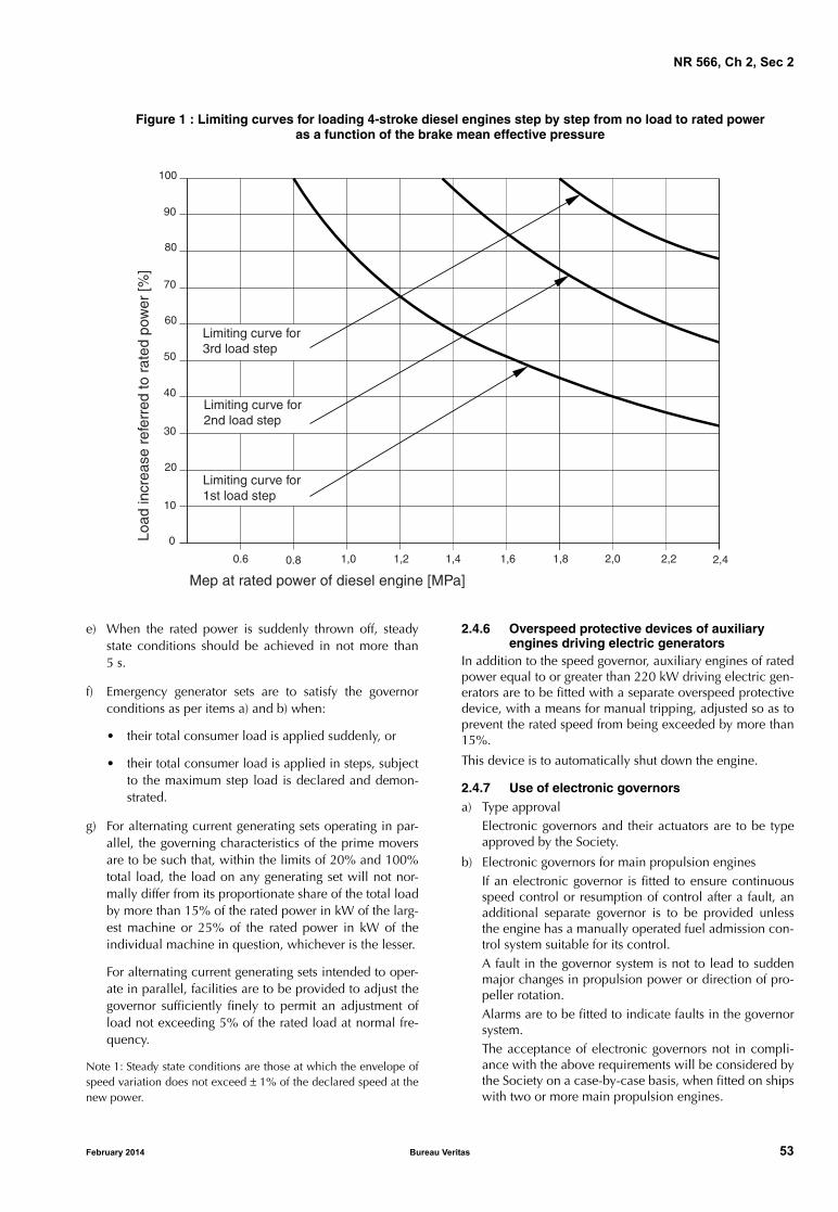
NR 566, Ch 2, Sec 2
Figure 1 : Limiting curves for loading 4-stroke diesel engines step by step from no load to rated poweras a function of the brake mean effective pressure
Mep at rated power of diesel engine [MPa]
Load
incr
ease
ref
erre
d to
rat
ed p
ower
[%]
Limiting curve for3rd load step
Limiting curve for2nd load step
Limiting curve for1st load step
0.6 0.8 1,0 1,2 1,4 1,6 1,8 2,0 2,2 2,4
100
90
80
70
60
50
40
30
20
10
0
e) When the rated power is suddenly thrown off, steadystate conditions should be achieved in not more than5 s.
f) Emergency generator sets are to satisfy the governorconditions as per items a) and b) when:
• their total consumer load is applied suddenly, or
• their total consumer load is applied in steps, subjectto the maximum step load is declared and demon-strated.
g) For alternating current generating sets operating in par-allel, the governing characteristics of the prime moversare to be such that, within the limits of 20% and 100%total load, the load on any generating set will not nor-mally differ from its proportionate share of the total loadby more than 15% of the rated power in kW of the larg-est machine or 25% of the rated power in kW of theindividual machine in question, whichever is the lesser.
For alternating current generating sets intended to oper-ate in parallel, facilities are to be provided to adjust thegovernor sufficiently finely to permit an adjustment ofload not exceeding 5% of the rated load at normal fre-quency.
Note 1: Steady state conditions are those at which the envelope ofspeed variation does not exceed ± 1% of the declared speed at thenew power.
February 2014 Bureau Ve
2.4.6 Overspeed protective devices of auxiliary engines driving electric generators
In addition to the speed governor, auxiliary engines of ratedpower equal to or greater than 220 kW driving electric gen-erators are to be fitted with a separate overspeed protectivedevice, with a means for manual tripping, adjusted so as toprevent the rated speed from being exceeded by more than15%.
This device is to automatically shut down the engine.
2.4.7 Use of electronic governors a) Type approval
Electronic governors and their actuators are to be typeapproved by the Society.
b) Electronic governors for main propulsion enginesIf an electronic governor is fitted to ensure continuousspeed control or resumption of control after a fault, anadditional separate governor is to be provided unlessthe engine has a manually operated fuel admission con-trol system suitable for its control.A fault in the governor system is not to lead to suddenmajor changes in propulsion power or direction of pro-peller rotation.Alarms are to be fitted to indicate faults in the governorsystem.The acceptance of electronic governors not in compli-ance with the above requirements will be considered bythe Society on a case-by-case basis, when fitted on shipswith two or more main propulsion engines.
ritas 53

NR 566, Ch 2, Sec 2
c) Electronic governors for auxiliary engines driving elec-tric generators
In the event of a fault in the electronic governor system,the fuel admission is to be set to “zero”.
Alarms are to be fitted to indicate faults in the governorsystem.
The acceptance of electronic governors fitted onengines driving emergency generators will be consid-ered by the Society on a case-by-case basis.
2.4.8 Monitoring: indications
Diesel engines installed on ships are to be equipped withindicators as detailed below:
a) For engine of 1000 kW and above:
The requirements laid down in Tab 2, Tab 3 and Tab 4 ofthe Rules for Steel Ships, Pt C, Ch 1, Sec 2 apply
b) For engine with a power less than 1000 kW:
• lubrication oil pressure indication
• fresh water temperature indication.
The indicators are to be fitted at a normally attended posi-tion (on the engine or at local control station).
2.4.9 Monitoring: alarms
Diesel engines installed on ships are to be equipped withalarms as detailed below:
a) For engine of 1000 kW and above:
The requirements laid down in Tab 2, Tab 3 and Tab 4 ofthe Rules for Steel Ships, Pt C, Ch 1, Sec 2 apply
b) For engine with a power less than 1000 kW:
• lubrication oil low pressure alarm
• very low lubricating oil pressure alarm
• overspeed alarm.
The alarms are to be visual and audible at a normallyattended position (on the engine or at local control station).
2.4.10 Automatic control: shut-down
Diesel engines installed on ships are to be equipped withautomatic control as detailed below:
a) For engine of 1000 kW and above:
The requirements laid down in Tab 2, Tab 3 and Tab 4 ofthe Rules for Steel Ships, Pt C, Ch 1, Sec 2 apply
b) For engine with a power less than 1000 kW:
• shut-down on very low lubricating oil pressure
• shut-down on overspeed.
2.4.11 Reduction in monitoring equipment and automatic control
In the following cases, the acceptance of a reduction in themonitoring equipment and automatic control required in[2.4.8] to [2.4.10] may be considered:
• main propulsion engines for ships with two or more pro-pulsion plants
• engines with power less than 220 kW
• ships with restricted navigation.
54 Bureau Ve
3 Reduction gear - Transmissions
3.1 General
3.1.1 DesignReduction gear and transmissions are to be of marine typeand suitably matched to the engine with which they are tobe used.
3.1.2 ApprovalWhere the power per shaft line exceeds 220 kW, reductiongear and transmissions are to be in compliance with the rel-evant requirements of the Rules for Steel Ships, Pt C, Ch 1,Sec 6.
3.2 Design and construction
3.2.1 Lubricating oilReduction gear incorporating an independent oiling systemis to include a suitable oil sump, an oil level indicatingdevice, and a vent located to provide adequate breathing,but positioned to prevent oil leakage from the transmissionunder normal operating conditions.
3.2.2 CoolingReduction gear and transmissions are to be provided with amethod of cooling so that recommended maximum sumptemperatures will not be exceeded under normal operatingconditions.
3.2.3 MonitoringHydraulically actuated transmissions are to have a provisionto monitor oil pressure and/or oil temperature.
4 Shafting
4.1 General
4.1.1 Application
a) Scantling rules mentioned in this Article are applicableto propulsion shaft line, whatever the power per shaftmay be
b) For shafting components in engines, gears and mainpropulsion thrusters, refer to the relevant requirementsof, respectively, Pt C, Ch 1, Sec 2, Pt C, Ch 1, Sec 6 andPt C, Ch 1, Sec 12 of the Rules for Steel Ships.
4.1.2 MaterialsMaterials used for elements covered by this Article should,as a rule, comply with the requirements of NR216, Materi-als and Welding. Use of other materials are to be subject tospecial examination.
4.2 Shafting scantling
4.2.1 Propeller shaft diameter
a) The diameter of the shaft going through the stern tube isnot to be less than the diameter d, in mm, given by thefollowing formula:
d = K (P / N) 1/3
ritas February 2014

NR 566, Ch 2, Sec 2
where:
P : Brake power, in kW
N : Shaft revolutions per minute
K : Coefficient having the values given in Tab 1.
Furthermore, the shaft diameter is not to be less than25 mm for carbon steel or carbon manganese steel, and20 mm for the other materials listed in Tab 1.
The use of materials other than those included in Tab 1is to be subject to special examination.
b) When the propeller shaft is made out of carbon manga-nese steel and is protected by a continuous liner or byoil lubrication with approved oil sealing gland, the coef-ficient K is given by the following formula:
K = 126 {560 / (Rm + 160)} 1/3
where:
Rm : Value of the minimum tensile strength of theshaft material, in N/mm2. The value of Rm tobe introduced in the formula is not to betaken higher than 600 N/mm2.
Table 1 : Values of coefficient K
4.2.2 Intermediate shaft diameter
The diameter d’, in mm, of the intermediate shafts is not tobe less than:
d’ = 0,8 K (P / N) 1/3
where P, N and K are defined in [4.2.1].
4.2.3 Hollow shaft
Where hollow shafts are used, the required diameter deter-mined according to the formulae given in [4.2.1] and[4.2.2] are to be multiplied by the factor Kd as indicated inTab 2, with:
Q : Ratio of the internal diameter to the outer shaftdiameter.
MaterialReH mini, in N/mm2
Rm mini, in N/mm2
K
Carbon and carbon manganese steel
200 400 126
Austenitic stainless steel (type 316)
175 470 91
Manganese bronze 245 510 92
Martensitic stainless steel (type 431)
675 850 88
Ni-Al bronze 390 740 85
Nickel-copper alloy (Monel 400)
350 550 85
Nickel-copper alloy (Monel K 500)
690 960 71
Duplex stainless steel (type S31803)
450 650 63
February 2014 Bureau Ve
Table 2 : Values of coefficient Kd
A central hole of diameter less than 0,4 of the shaft diame-ter may be accepted without increase in shaft size.
4.2.4 Cardan shaft
Characteristics of the cardan shaft and justification of thecardan shaft life duration are to be submitted for informa-tion.
4.3 Shafting accessories
4.3.1 Coupling flanges
a) The thickness of inboard coupling flanges, at the pitchcircle of the bolt holes, is not to be less than therequired diameter of the corresponding bolts deter-mined as indicated in [4.3.2], paying due regard to thespecified minimum tensile strength of the material ofsaid flanges. Besides, the thickness of the propeller shaftcoupling flange is not to be less than 0,20 times therequired diameter of the intermediate shaft, calculatedpaying due regard to the specified minimum tensilestrength of the material of said flange.
The fillets of coupling flanges at their junction with theshafts are to have a radius at least equal to 8% of thediameter of the corresponding shaft.
b) Outboard coupling flanges are to have a thickness notless than 0,25 times the required diameter of the corre-sponding shaft. The fillet radius at the junction with theshaft is not to be less than half the required thickness ofthe flange.
c) The fillets are to be carefully machined and, as a rule,recesses are to be avoided as far as possible in way ofbolt heads and nuts.
4.3.2 Coupling bolts
a) The diameter of fitted coupling bolts at the joining facesof the couplings is to be not less than the diameter Db
given, in mm, by the following formula, for intermedi-ate, propeller and thrust shafts:
where:
n : Number of bolts in the coupling
r : Radius of the pitch circle of the bolts, in mm
Rb : Ultimate tensile strength of the bolt metal, inN/mm2
P, N : As defined in [4.2.1].
b) For the fitted bolts of coupling flanges for crankshaftparts as well as of coupling flanges between crankshaftsand thrust and flywheel-shafts, the above formula is tobe applied but the factor 11.103 is to be superseded by14.103.
Q 0,4 0,5 0,6 0,7
Kd 1,01 1,02 1,05 1,10
Db 11.103 Pn r Rb N⋅ ⋅ ⋅-----------------------------
1 2⁄
=
ritas 55

NR 566, Ch 2, Sec 2
c) Flange coupling with non-fitted coupling bolts may beaccepted on the basis of the calculation of bolts tighten-ing, bolts stress due to tightening and assembly con-struction. Refer to relevant requirements of the Rules forSteel Ships, Pt C, Ch 1, Sec 7, [2.5.1].
d) Where the pieces of the shafting are not joined bymeans of forged coupling flanges, the arrangement is tobe given special consideration by the Society; in thiscase, provision is to be made for the coupling to resistthe rated astern pull.
e) Where the shafts have peculiar machining such asgrooves, longitudinal slots or transverse holes, thedesign is to be such as to reduce stress concentrations. Alocal increase of the shaft diameter may be required bythe Society.
4.3.3 Shaft liners
a) Propeller shafts of carbon steel are to be protected by acontinuous salt water resistant liner where exposed tosea water. Alternatively, the liner may be omitted pro-vided the shaft runs in an oil lubricated stern tube withan approved sealing gland at the after end. Length ofshafting between stern tube and propeller bracket maybe protected by suitable coatings.
b) The thickness of bronze shaft liners in way of the bushesand sterngland is to be not less than the thickness e, inmm, given by the following formula:
where:
d : Actual diameter of the propeller shaft, in mm.
c) The thickness of the continuous liner between thebushes is to be, as a rule, not less than 0,75 e.
The liners are considered as continuous when they are:
• either cast in one piece, or
• made of two or more lengths assembled by joints ofan approved type.
d) Where parts of liners are assembled by welding,arrangements are to be made to protect the surface ofthe shaft during welding and to allow the free contrac-tion of the joint after welding.
e) The joints between liner parts are not to be located inway of the bushes or sterngland.
f) Each continuous liner or length of liner is to be tested byhydraulic pressure to 2 bar after rough machining.
g) Liners are to be carefully shrunk on the shafts eitherwhilst hot, or by hydraulic press, or by any otherapproved process. Pins or other similar devices are notto be used to secure the liners on the shafts.
h) Where ways are provided between liner and propellershaft outside the bearings, these ways are to be filledwith a material insoluble in water and non-corrosive.
i) Means are to be provided, particularly at the junction ofliner and propeller boss, to prevent any entry of seawater under the liner and on the propeller boss.
e d 230+32
-------------------=
56 Bureau Ve
4.3.4 Stern tube bearings
a) Oil lubricated bearings of white metal
The length of white metal lined bearings is to be not lessthan 2,0 times the rule diameter of the shaft in way ofthe bearing.
The length of the bearing may be less than that givenabove, provided the nominal bearing pressure is notmore than 0,8 N/mm2, as determined by static bearingreaction calculations taking into account shaft and pro-peller weight, as exerting solely on the aft bearing,divided by the projected area of the shaft.
However, the minimum bearing length is to be not lessthan 1,5 times its actual inner diameter.
b) Oil lubricated bearings of synthetic rubber, reinforcedresin or plastic materials
For bearings of synthetic rubber, reinforced resin or plas-tic materials which are approved for use as oil lubri-cated stern bush bearings, the length of the bearing is tobe not less than 2,0 times the rule diameter of the shaftin way of the bearing.
The length of the bearing may be less than that givenabove provided the nominal bearing pressure is not morethan 0,6 N/mm2, as determined according to item a).
However, the minimum length of the bearing is to benot less than 1,5 times its actual inner diameter.
Where the material has proven satisfactory testing andoperating experience, consideration may be given to anincreased bearing pressure.
c) Water lubricated bearings of synthetic materials
Where the bearing is constructed of synthetic materialswhich are approved for use as water lubricated sternbush bearings, such as rubber or plastics, the length ofthe bearing is to be not less than 4,0 times the rulediameter of the shaft in way of the bearing
For a bearing design substantiated by experiments to thesatisfaction of the Society, consideration may be givento a bearing length not less than 2,0 times the rule diam-eter of the shaft in way of the bearing.
d) Other arrangements
The other arrangements beside those defined in items a),b) and c) are to be given special consideration. Thelength of the after bearing of the propeller shaft is to benot less than 4,0 times the rule diameter of the shaft inway of the bearing.
e) Where the bearings are lubricated by water, arrange-ments are to be made for an adequate supply of water.
A forced water lubrication is to be provided, if neces-sary, namely for bearings lined with lignum vitae, rub-ber or plastic materials.
f) For oil lubricated bearings and where the lubrication ismade by gravity, the lubricating oil tank is to be locatedabove the load centre water line. In this case, a lowlevel indication or preferably an alarm is to be given atthe operator's position.
ritas February 2014

NR 566, Ch 2, Sec 2
4.3.5 Sealing glands
a) The sealing glands are to be readily accessible, forinspection or replacement.
b) The sealing glands are to be periodically inspected.
c) It is to be mentioned, in the Owner's manual, all neces-sary measures to be taken in case of accidental breakingof a main element, as well as the periodicity of inspec-tions and replacement of elements subject to deteriora-tion or wearing.
d) The wear strength of non-metallic parts is to be estab-lished, either by satisfactory operations, or by relevanttests.
An easy to fit emergency device may be accepted.
4.3.6 Propeller shaft keys and keywaysSee relevant requirements of the Rules for Steel Ships, Pt C,Ch 1, Sec 7, [2.5.5].
5 Propeller
5.1 Scantlings
5.1.1 Propeller scantlings are to comply with the require-ments of the Rules for Steel Ships, Pt C, Ch 1, Sec 8.
5.1.2 The Society may agree, for propellers, scantlings jus-tified by either adequate calculations, or satisfactory experi-ence in service.
6 Shaft vibrations
6.1 General
6.1.1 ApplicationA torsional vibration calculation is to be submitted forreview for the shafting of the following installation in com-pliance with the relevant requirements of the Rules for SteelShips, Pt C, Ch 1, Sec 9:
• propulsion systems with prime movers developing220 kW or more
• other systems with internal combustion engines devel-oping 110 kW or more and driving auxiliary machineryintended for essential services.
February 2014 Bureau Ve
7 Shaft alignment
7.1 General
7.1.1 Application and calculation requirementsIn general, the shaft alignment calculations and the shipyard’s shaft alignment procedures indicating the proposedalignment method and alignment verification after installa-tion (such as gap and sag, jack-up, laser or strain gauges,etc.), for cold, hot static and dynamic conditions, are to besubmitted to the Society’s review when the shaft diameter is350 mm or greater in way of the aftermost stern tube bear-ing.
The Society may also require the above calculations in thecase of special arrangements.
Refer to the relevant requirements of the Rules for SteelShips, Pt C, Ch 1, Sec 7, [3.3].
7.1.2 Practical shaft alignment operationThe alignment of the propulsion machinery and shaftingand the spacing and location of the bearings are to be suchas to ensure that the loads are compatible with the materialused and the limits prescribed by the Manufacturer.
Shaft alignment should be carried out with the ship floatingand should be checked occasionally or if unusual vibrationis evident.
The alignment is to be checked on board by the Shipyard bya suitable measurement method.
8 Thrusters and waterjets
8.1 General
8.1.1 Thrusters and waterjets developing power equal to, or more than, 110 kW
Thrusters and waterjets developing power equal to, or morethan, 110 kW intended for propulsion and steering are to bein compliance with the relevant requirements of the Rulesfor Steel Ships, Pt C, Ch 1, Sec 12.
8.1.2 Thrusters and waterjets developing power less than 110 kW
Thrusters and waterjets developing power less than 110 kWintended for propulsion and steering are to built in accord-ance with sound marine practice.
ritas 57
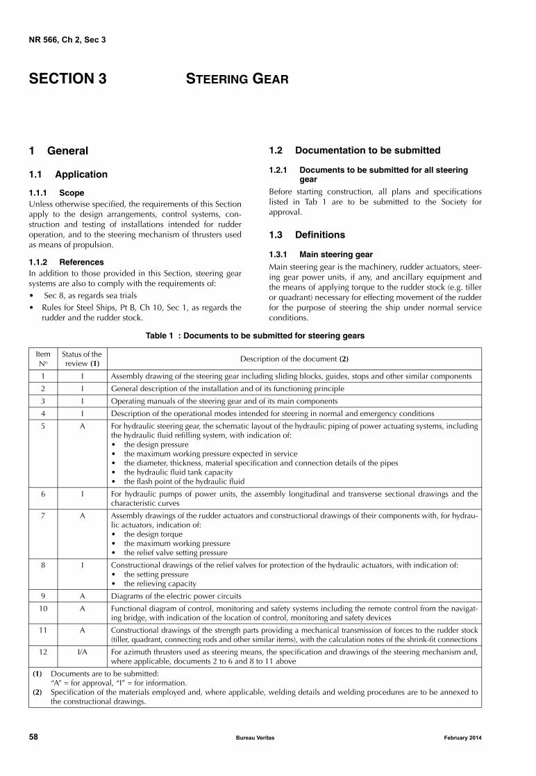
NR 566, Ch 2, Sec 3
SECTION 3 STEERING GEAR
1 General
1.1 Application
1.1.1 ScopeUnless otherwise specified, the requirements of this Sectionapply to the design arrangements, control systems, con-struction and testing of installations intended for rudderoperation, and to the steering mechanism of thrusters usedas means of propulsion.
1.1.2 ReferencesIn addition to those provided in this Section, steering gearsystems are also to comply with the requirements of:• Sec 8, as regards sea trials• Rules for Steel Ships, Pt B, Ch 10, Sec 1, as regards the
rudder and the rudder stock.
58 Bureau Ve
1.2 Documentation to be submitted
1.2.1 Documents to be submitted for all steering gear
Before starting construction, all plans and specificationslisted in Tab 1 are to be submitted to the Society forapproval.
1.3 Definitions
1.3.1 Main steering gearMain steering gear is the machinery, rudder actuators, steer-ing gear power units, if any, and ancillary equipment andthe means of applying torque to the rudder stock (e.g. tilleror quadrant) necessary for effecting movement of the rudderfor the purpose of steering the ship under normal serviceconditions.
Table 1 : Documents to be submitted for steering gears
Item No
Status of the review (1) Description of the document (2)
1 I Assembly drawing of the steering gear including sliding blocks, guides, stops and other similar components
2 I General description of the installation and of its functioning principle
3 I Operating manuals of the steering gear and of its main components
4 I Description of the operational modes intended for steering in normal and emergency conditions
5 A For hydraulic steering gear, the schematic layout of the hydraulic piping of power actuating systems, includingthe hydraulic fluid refilling system, with indication of:• the design pressure• the maximum working pressure expected in service• the diameter, thickness, material specification and connection details of the pipes• the hydraulic fluid tank capacity• the flash point of the hydraulic fluid
6 I For hydraulic pumps of power units, the assembly longitudinal and transverse sectional drawings and thecharacteristic curves
7 A Assembly drawings of the rudder actuators and constructional drawings of their components with, for hydrau-lic actuators, indication of:• the design torque• the maximum working pressure• the relief valve setting pressure
8 I Constructional drawings of the relief valves for protection of the hydraulic actuators, with indication of:• the setting pressure• the relieving capacity
9 A Diagrams of the electric power circuits
10 A Functional diagram of control, monitoring and safety systems including the remote control from the navigat-ing bridge, with indication of the location of control, monitoring and safety devices
11 A Constructional drawings of the strength parts providing a mechanical transmission of forces to the rudder stock(tiller, quadrant, connecting rods and other similar items), with the calculation notes of the shrink-fit connections
12 I/A For azimuth thrusters used as steering means, the specification and drawings of the steering mechanism and,where applicable, documents 2 to 6 and 8 to 11 above
(1) Documents are to be submitted:“A” = for approval, “I” = for information.
(2) Specification of the materials employed and, where applicable, welding details and welding procedures are to be annexed tothe constructional drawings.
ritas February 2014
NR 566, Ch 2, Sec 3
1.3.2 Auxiliary steering gear
Auxiliary steering gear is the equipment other than any partof the main steering gear necessary to steer the ship in theevent of failure of the main steering gear but not includingthe tiller, quadrant or components serving the same pur-pose.
1.3.3 Types of steering gear
Main and auxiliary steering gears may be:
• electric, when both the power source and the ruddertorque transmission is electric
• electrohydraulic, when the power source is electric andthe rudder torque transmission is hydraulic
• engine hydraulic, when the power source is an internalcombustion engine and the rudder torque transmissionis hydraulic
• manual hydraulic, when the power source is humanforce and the rudder torque transmission is hydraulic
• manual mechanic, when the power source is humanforce and the rudder torque transmission is mechanic.
1.3.4 Steering gear power unit
Main and auxiliary steering gear power units are:
• in the case of electric steering gear, an electric motorand its associated electrical equipment
• in the case of electrohydraulic steering gear, an electricmotor and its associated electrical equipment and con-nected pump
• in the case of engine hydraulic steering gear, a drivingengine and connected pump
• in the case of manual hydraulic steering gear, a handpump (could be combined with a steering wheel)
• in the case of manual mechanic steering gear, a steeringwheel (main steering gear) or manual lever on top ofrudder stock (auxiliary steering gear).
1.3.5 Power actuating system
Power actuating system is the equipment provided for sup-plying power to turn the rudder stock, comprising a steeringgear power unit or units, together with the associated pipesand fittings, and a rudder actuator. The power actuating sys-tems may share common mechanical components, i.e.tiller, quadrant and rudder stock, or components serving thesame purpose.
1.3.6 Rudder actuator
Rudder actuator is the component which directly convertshydraulic pressure into mechanical action to move the rud-der.
1.3.7 Steering gear control system
Steering gear control system is the equipment by whichorders are transmitted from the navigation bridge to thesteering gear power units. Steering gear control systemscomprise transmitters, receivers, hydraulic control pumpsand their associated motors, motor controllers, piping andcables.
February 2014 Bureau Ve
1.3.8 Maximum ahead service speed
Maximum ahead service speed is the greatest speed theship is designed to maintain at sea in service condition.
1.3.9 Maximum astern speed
Maximum astern speed is the speed the ship is estimated tobe able to attain at the designed maximum astern power.
1.3.10 Maximum working pressure
Maximum working pressure is the maximum expected pres-sure in the system when the steering gear is operated tocomply with the provisions of [3.2.1].
1.3.11 Design pressure
Design pressure is the greatest of the following pressures:
• 1,25 times the maximum working pressure
• the setting pressure of the relief valves.
1.4 Symbols
1.4.1 The following symbols are used for strength criteria ofsteering gear components:
VAV : Maximum ahead service speed, in knots, withthe ship on summer load waterline; if VAV is lessthan 10 knots, the maximum service speed is tobe taken not less than the value VMIN obtainedfrom the following formula:
MTR : Rule rudder torque, in kN.m, as defined in theRules for Steel Ships, Pt B, Ch 10, Sec 1
ds : Rule rudder stock diameter with null bendingmoment in way of the tiller, in mm, defined inthe Rules for Steel Ships, Pt B, Ch 10, Sec 1 andcalculated with a material factor k1 = 1
dse : Actual diameter of the rudder stock in way ofthe tiller, in mm
(in the case of a tapered coupling, this diameteris measured at the base of the assembly)
σ : Normal stress due to bending moments and ten-sile/compression forces, in N/mm2
τ : Shear stress due to torsional moments and shearforces, in N/mm2
σa : Permissible stress (von Mises), in N/mm2
σc : Combined stress, determined by the followingformula:
Rm : Minimum ultimate tensile strength, in N/mm2,of the steel used
ReH : Minimum yield stress, in N/mm2, of the speci-fied steel, and not exceeding the lower of0,7 Rm and 450 N/mm2
VMINVAV 20+
3----------------------=
σc σ2 3τ2+=
ritas 59
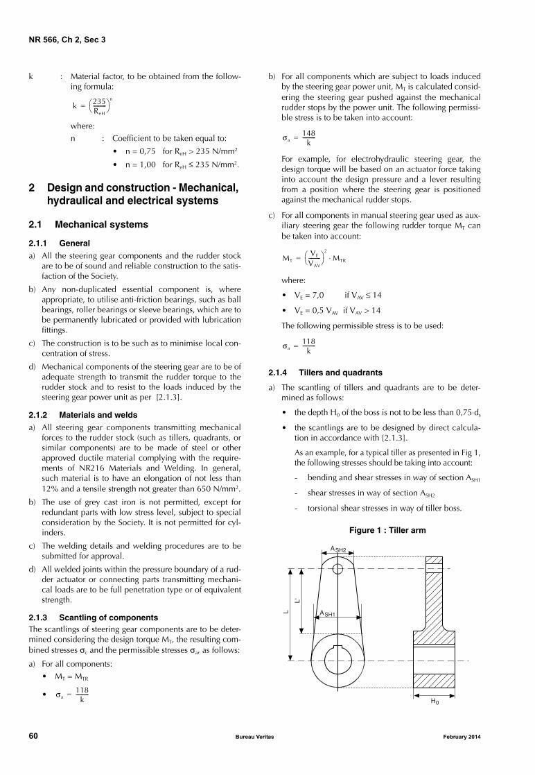
NR 566, Ch 2, Sec 3
k : Material factor, to be obtained from the follow-ing formula:
where:n : Coefficient to be taken equal to:
• n = 0,75 for ReH > 235 N/mm2
• n = 1,00 for ReH ≤ 235 N/mm2.
2 Design and construction - Mechanical, hydraulical and electrical systems
2.1 Mechanical systems
2.1.1 Generala) All the steering gear components and the rudder stock
are to be of sound and reliable construction to the satis-faction of the Society.
b) Any non-duplicated essential component is, whereappropriate, to utilise anti-friction bearings, such as ballbearings, roller bearings or sleeve bearings, which are tobe permanently lubricated or provided with lubricationfittings.
c) The construction is to be such as to minimise local con-centration of stress.
d) Mechanical components of the steering gear are to be ofadequate strength to transmit the rudder torque to therudder stock and to resist to the loads induced by thesteering gear power unit as per [2.1.3].
2.1.2 Materials and weldsa) All steering gear components transmitting mechanical
forces to the rudder stock (such as tillers, quadrants, orsimilar components) are to be made of steel or otherapproved ductile material complying with the require-ments of NR216 Materials and Welding. In general,such material is to have an elongation of not less than12% and a tensile strength not greater than 650 N/mm2.
b) The use of grey cast iron is not permitted, except forredundant parts with low stress level, subject to specialconsideration by the Society. It is not permitted for cyl-inders.
c) The welding details and welding procedures are to besubmitted for approval.
d) All welded joints within the pressure boundary of a rud-der actuator or connecting parts transmitting mechani-cal loads are to be full penetration type or of equivalentstrength.
2.1.3 Scantling of componentsThe scantlings of steering gear components are to be deter-mined considering the design torque MT, the resulting com-bined stresses σc and the permissible stresses σa, as follows:
a) For all components:• MT = MTR
•
k 235ReH
----------
n
=
σa118
k---------- =
60 Bureau Ve
b) For all components which are subject to loads inducedby the steering gear power unit, MT is calculated consid-ering the steering gear pushed against the mechanicalrudder stops by the power unit. The following permissi-ble stress is to be taken into account:
For example, for electrohydraulic steering gear, thedesign torque will be based on an actuator force takinginto account the design pressure and a lever resultingfrom a position where the steering gear is positionedagainst the mechanical rudder stops.
c) For all components in manual steering gear used as aux-iliary steering gear the following rudder torque MT canbe taken into account:
where:
• VE = 7,0 if VAV ≤ 14
• VE = 0,5 VAV if VAV > 14
The following permissible stress is to be used:
2.1.4 Tillers and quadrants
a) The scantling of tillers and quadrants are to be deter-mined as follows:
• the depth H0 of the boss is not to be less than 0,75⋅ds
• the scantlings are to be designed by direct calcula-tion in accordance with [2.1.3].
As an example, for a typical tiller as presented in Fig 1,the following stresses should be taking into account:
- bending and shear stresses in way of section ASH1
- shear stresses in way of section ASH2
- torsional shear stresses in way of tiller boss.
Figure 1 : Tiller arm
σa148
k----------=
MTVE
VAV
---------
2
MTR⋅=
σa118
k---------- =
H0
L'
L ASH1
ASH2
ritas February 2014
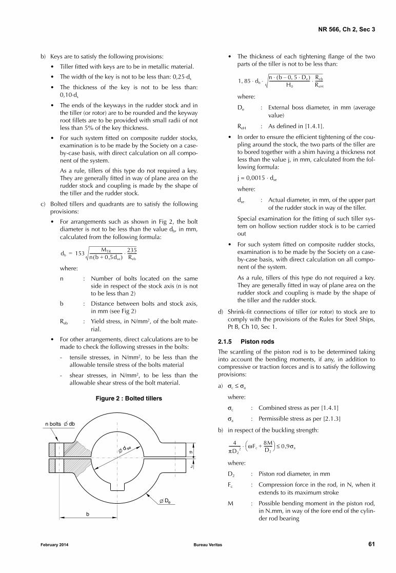
NR 566, Ch 2, Sec 3
b) Keys are to satisfy the following provisions:
• Tiller fitted with keys are to be in metallic material.
• The width of the key is not to be less than: 0,25⋅ds
• The thickness of the key is not to be less than:0,10⋅ds
• The ends of the keyways in the rudder stock and inthe tiller (or rotor) are to be rounded and the keywayroot fillets are to be provided with small radii of notless than 5% of the key thickness.
• For such system fitted on composite rudder stocks,examination is to be made by the Society on a case-by-case basis, with direct calculation on all compo-nent of the system.
As a rule, tillers of this type do not required a key.They are generally fitted in way of plane area on therudder stock and coupling is made by the shape ofthe tiller and the rudder stock.
c) Bolted tillers and quadrants are to satisfy the followingprovisions:
• For arrangements such as shown in Fig 2, the boltdiameter is not to be less than the value db, in mm,calculated from the following formula:
where:
n : Number of bolts located on the sameside in respect of the stock axis (n is notto be less than 2)
b : Distance between bolts and stock axis,in mm (see Fig 2)
Reb : Yield stress, in N/mm2, of the bolt mate-rial.
• For other arrangements, direct calculations are to bemade to check the following stresses in the bolts:
- tensile stresses, in N/mm2, to be less than theallowable tensile stress of the bolts material
- shear stresses, in N/mm2, to be less than theallowable shear stress of the bolt material.
Figure 2 : Bolted tillers
db 153MTR
n b 0 5dse,+( )---------------------------------- 235
Reb
----------⋅=
b
sed
dbn bolts
eD
J
th
February 2014 Bureau Ve
• The thickness of each tightening flange of the twoparts of the tiller is not to be less than:
where:
De : External boss diameter, in mm (averagevalue)
ReH : As defined in [1.4.1].
• In order to ensure the efficient tightening of the cou-pling around the stock, the two parts of the tiller areto bored together with a shim having a thickness notless than the value j, in mm, calculated from the fol-lowing formula:
j = 0,0015 ⋅ dse
where:
dse : Actual diameter, in mm, of the upper partof the rudder stock in way of the tiller.
Special examination for the fitting of such tiller sys-tem on hollow section rudder stock is to be carriedout
• For such system fitted on composite rudder stocks,examination is to be made by the Society on a case-by-case basis, with direct calculation on all compo-nent of the system.
As a rule, tillers of this type do not required a key.They are generally fitted in way of plane area on therudder stock and coupling is made by the shape ofthe tiller and the rudder stock.
d) Shrink-fit connections of tiller (or rotor) to stock are tocomply with the provisions of the Rules for Steel Ships,Pt B, Ch 10, Sec 1.
2.1.5 Piston rods
The scantling of the piston rod is to be determined takinginto account the bending moments, if any, in addition tocompressive or traction forces and is to satisfy the followingprovisions:
a) σc ≤ σa
where:
σc : Combined stress as per [1.4.1]
σa : Permissible stress as per [2.1.3]
b) in respect of the buckling strength:
where:
D2 : Piston rod diameter, in mm
Fc : Compression force in the rod, in N, when itextends to its maximum stroke
M : Possible bending moment in the piston rod,in N.mm, in way of the fore end of the cylin-der rod bearing
1 85, dbn b 0 5, De⋅–( )⋅
H0
------------------------------------------ Reb
ReH
--------⋅⋅ ⋅
4πD2
2------------ ωFc
8MD2
---------+ 0 9σa,≤⋅
ritas 61

NR 566, Ch 2, Sec 3
ω = β + (β2 − α)0,5
with:
α = 0,0072 (s ⋅ D2)2 ⋅ R’e / 235
β = 0,48 + 0,5 α + 0,1 α0,5
s : Length, in mm, of the maximum unsup-ported reach of the cylinder rod.
2.2 Hydraulical systems
2.2.1 General
a) The design pressure for calculations to determine thescantlings of piping and other steering gear componentssubjected to internal hydraulic pressure is to be at least1,25 times the maximum working pressure to beexpected under the operational conditions specified in[3], taking into account any pressure which may exist inthe low pressure side of the system.
b) The power piping for hydraulic steering gear is to bearranged so that transfer between units can be readilyeffected.
c) Arrangements for bleeding air from the hydraulic systemare to be provided, where necessary.
d) The hydraulic piping system, including joints, valves,flanges and other fittings, is to comply with the require-ments of Sec 4 for class I piping systems.
2.2.2 Materials
a) Ram cylinders, pressure housings of rotary vane typeactuators, hydraulic power piping, valves, flanges and fit-tings are to be of steel or other approved ductile material.
b) In general, such material is to have an elongation of notless than 12% and a tensile strength not greater than650 N/mm2.
Grey cast iron may be accepted for valve bodies andredundant parts with low stress level, excluding cylin-ders, subject to special consideration.
2.2.3 Isolating valves
Shut-off valves, non-return valves or other appropriatedevices are to be provided to comply with the availabilityrequirements of [3.4].
2.2.4 Relief valves
a) Relief valves are to be fitted to any part of the hydraulicsystem which can be isolated and in which pressure canbe generated from the power source or from externalforces. The setting of the relief valves is not to exceedthe design pressure. The valves are to be of adequatesize and so arranged as to avoid an undue rise in pres-sure above the design pressure.
b) The setting pressure of the relief valves is not to be lessthan 1,25 times the maximum working pressure.
c) The minimum discharge capacity of the relief valve(s) isnot to be less than the total capacity of the pumps whichcan deliver through it (them), increased by 10%. Undersuch conditions, the rise in pressure is not to exceed
62 Bureau Ve
10% of the setting pressure. In this respect, due consid-eration is to be given to the foreseen extreme ambientconditions in relation to oil viscosity.
2.2.5 Hydraulic oil reservoirs
Hydraulic power-operated steering gear is to be providedwith the following:
• a low level alarm for each hydraulic fluid reservoir togive the earliest practicable indication of hydraulic fluidleakage
Audible and visual alarms are to be given on the naviga-tion bridge and in the machinery space where they canbe readily observed.
• where the main steering gear is required to be poweroperated, a storage mean, as a readily accessible drum,having sufficient capacity to recharge at least one poweractuating system if necessary.
2.2.6 Hydraulic pumps
Hydraulic pumps are to be type tested in accordance withthe provisions of [7.1.1].
2.2.7 Filters
a) Hydraulic power-operated steering gears are to be pro-vided with arrangements to maintain the cleanliness ofthe hydraulic fluid taking into consideration the typeand design of the hydraulic system.
b) Filters of appropriate mesh fineness are to be providedin the piping system, in particular to ensure the protec-tion of the pumps.
2.2.8 Hydraulic power supply
Hydraulic power installations supplying steering gear mayalso supply other equipment at the same time provided that:
a) the operation of the steering gear is not affected by theoperation of this equipment
b) the piping system of this system can be isolated from thesteering gear system by means of closing valves.
2.2.9 Accumulators
Accumulators, if fitted, are to be designed in accordancewith Sec 7, [5.5.3].
2.2.10 Rudder actuators
a) Rudder actuators are to be designed in accordance withthe relevant requirements of the Rules for Steel Ships, PtC, Ch 1, Sec 3 for class 1 pressure vessels, consideringalso the following provisions.
b) The permissible primary general membrane stress is notto exceed the lower of the following values:
where A and B are given in Tab 2.
c) Oil seals between non-moving parts, forming part of theexternal pressure boundary, are to be of metal uponmetal or equivalent type.
RA---- or
Re
B-----
ritas February 2014
NR 566, Ch 2, Sec 3
d) Oil seals between moving parts, forming part of theexternal pressure boundary, are to be duplicated, so thatthe failure of one seal does not render the actuator inop-erative. Alternative arrangements providing equivalentprotection against leakage may be accepted.
e) The strength and connection of the cylinder heads (or, inthe case of actuators of the rotary type, the fixed vanes)acting as rudder stops are to comply with the provisionsof [6.3.1].
Table 2 : Coefficients A and B
2.3 Electrical systems
2.3.1 ApplicationThe provisions of [2.3.2] to [2.3.6] apply to all electric orelectrohydraulic steering gear.
The provisions of [2.3.7] and [2.3.8] apply to steering gearwhere main and auxiliary steering gears are electric or elec-trohydraulic.
2.3.2 Power circuit supplyThe circuits supplying electric or electrohydraulic steeringgear are to have adequate rating for supplying all motorswhich can be simultaneously connected to them and maybe required to operate simultaneously.
The main electric or electrohydraulic steering gear is to besupplied directly by the main switchboard.
2.3.3 Motors and associated control gear
a) To determine the required characteristics of the electricmotors for power units, the breakaway torque and maxi-mum working torque of the steering gear under all oper-ating conditions are to be considered. The ratio of pull-out torque to rated torque is to be at least 1,6.
b) Motors for steering gear power units may be rated forintermittent power demand.
The rating is to be determined on the basis of the steer-ing gear characteristics of the ship in question; the ratingis always to be at least:
• S3 − 40% for motors of electric steering gear powerunits
• S6 − 25% for motors of electrohydraulic steeringgear power units and for convertors.
c) Each electric motor of a main or auxiliary steering gearpower unit is to be provided with its own separatemotor starter gear, located within the steering gear com-partment.
2.3.4 Supply of motor control circuits and steering gear control systems
a) Each control for starting and stopping of motors forpower units is to be served by its own control circuitssupplied from its respective power circuits.
Coefficient Steel Cast steel Nodular cast iron
A 3,5 4 5
B 1,7 2 3
February 2014 Bureau Ve
b) Any electrical main and auxiliary steering gear controlsystem operable from the navigating bridge is to beserved by its own separate circuit supplied from a steer-ing gear power circuit from a point within the steeringgear compartment, or directly from switchboard busbarssupplying that steering gear power circuit at a point onthe switchboard adjacent to the supply to the steeringgear power circuit. The power supply systems are to beprotected selectively.
2.3.5 Circuit protection
a) Short-circuit protection is to be provided for each con-trol circuit and each power circuit of electric or electro-hydraulic main and auxiliary steering gears.
b) No protection other than short-circuit protection is to beprovided for steering gear control system supply circuits.
c) Protection against excess current (e.g. by thermalrelays), including starting current, if provided for powercircuits, is to be for not less than twice the full load cur-rent of the motor or circuit so protected, and is to bearranged to permit the passage of the appropriate start-ing currents.
d) Steering gear motor circuits obtaining their power sup-ply via an electronic converter, e.g. for speed control,and which are limited to full load current are exemptfrom the requirement to provide protection againstexcess current, including starting current, of not lessthan twice the full load current of the motor. Therequired overload alarm is to be set to a value notgreater than the normal load of the electronic converter.
Note 1: “Normal load” is the load in normal mode of operationthat approximates as close as possible to the most severe con-ditions of normal use in accordance with the manufacturer’soperating instructions.
e) Where fuses are fitted, their current ratings are to betwice the rated current of the motors. However, in thecase of intermittent service motors, the fuse rating is notto exceed 160% of the rated motor current.
f) The instantaneous short-circuit trip of circuit breakers isto be set to a value not greater than 15 times the ratedcurrent of the drive motor.
g) The protection of control circuits is to correspond to atleast twice the maximum rated current of the circuit,though not, if possible, below 6 A.
2.3.6 Starting and stopping of motors for steering gear power units
a) Motors for power units are to be capable of beingstarted and stopped from a position on the navigationbridge and from a point within the steering gear com-partment.
b) Means are to be provided at the position of motor start-ers for isolating any remote control starting and stoppingdevices (e.g. by removal of the fuse-links or switchingoff the automatic circuit breakers).
c) Main and auxiliary steering gear power units are to bearranged to restart automatically when power is restoredafter a power failure.
ritas 63

NR 566, Ch 2, Sec 3
Table 3 : Location of displays and alarms
Item DisplayAlarms
(audible and visible)
Location
Navigation Bridge (1)
Steering gear compartment
Steering gear compartment
or engine room
Indication that electric motor of each power unit is running
X X X
Power failure of each power unit X G X
Overload of electric motor of each power unit X G X
Phase failure of electric motor of each power unit (2) X G X
Low level of each hydraulic fluid reservoir X G X
Hydraulic lock X G X
Power failure of each control system X X
Rudder angle indicator X X X
(1) G: Group alarm(2) Where three-phase supply is used.
2.3.7 Power circuit supply in case of electric or electrohydraulic main and auxiliary steering gears
a) Electric or electrohydraulic steering gear is to be servedby at least two exclusive circuits fed directly from themain switchboard; however one of the circuits may besupplied through the emergency switchboard.
b) Auxiliary electric or electrohydraulic steering gear, asso-ciated with main electric or electrohydraulic steeringgear, may be connected to one of the circuits supplyingthe main steering gear.
2.3.8 Separation in case of electric or electrohydraulic main and auxiliary steering gears
a) Where electric or electrohydraulic main and auxiliarysteering gears are provided, the supply and associatedcontrol cables are to follow different routes which are tobe as far as practicable separated both vertically andhorizontally.
b) In the case of double follow-up control, the amplifier isto be designed and fed so as to be electrically andmechanically separated. In the case of non-follow-upcontrol and follow-up control, it is to be ensured thatthe follow-up amplifier is protected selectively.
c) Control circuits for additional control systems, e.g.steering lever or autopilot, are to be designed for all-pole disconnection.
d) The feedback units and limit switches, if any, for thesteering gear control systems are to be separated electri-cally and mechanically connected to the rudder stock oractuator separately.
2.4 Control, monitoring and alarm systems
2.4.1 Displays and alarms
Displays and alarms are to be provided in the locationsindicated in Tab 3.
64 Bureau Ve
2.4.2 Rudder angle indication
The angular position of the rudder is to be indicated on thenavigating bridge, if the main steering gear is power oper-ated. The rudder angle indication is to be independent ofthe steering gear control system and be supplied throughthe emergency switchboard, or by an alternative and inde-pendent source of electrical power.
3 Design and construction - Performance and availability
3.1 General provisions
3.1.1 Every ship is to be provided with main steering gearand auxiliary steering gear to the satisfaction of the Society.
3.2 Performance and power operation of the steering gear
3.2.1 Main steering gear
The main steering gear and rudder stock are to be:
a) capable of steering the ship at maximum ahead servicespeed, which is to be demonstrated
b) capable of putting the rudder over from 35° on one sideto 35° on the other side with the ship at its deepest sea-going draught and running ahead at maximum aheadservice speed and, under the same conditions, from 35°on either side to 30° on the other side in not more than28 s
c) operated by power where necessary to fulfil the require-ments of item b), and
d) so designed that they will not be damaged at maximumastern speed; however, this design requirement need notbe proved by trials at maximum astern speed and maxi-mum rudder angle.
ritas February 2014

NR 566, Ch 2, Sec 3
3.2.2 Auxiliary steering gear
The auxiliary steering gear is to be:
a) sufficient to steer the ship at navigable speed
b) capable of putting the rudder over from 15° on one sideto 15° on the other side in not more than 60 s with theship at its deepest seagoing draught and running aheadat one half of the maximum ahead service speed or7 knots, whichever is the greater, and
c) operated by power where necessary to meet the require-ments of item b)
d) operational rapidly
If the operation of the auxiliary steering gear requiresimmobilisation of the tiller, an efficient braking system isto be installed. In case of hydraulic steering gear, brak-ing may be obtained by shutting off the isolating valves,fitted directly on the actuator.
3.2.3 Hand operation
As a rule, operation of hand operated steering gears shouldnot require an effort exceeding 160 N under normal condi-tions.
3.3 Control of the steering gear
3.3.1 Control of the main steering gear
Control of the main steering gear is to be provided on thenavigation bridge.
3.3.2 Control of the auxiliary steering gear
Control of the auxiliary steering gear is to be provided onthe navigation bridge, in the steering gear compartment orin another suitable position.
3.4 Arrangement of main and auxiliary steering gears
3.4.1 Availability
The main steering gear and the auxiliary steering gear are tobe arranged so that failure of one of the following compo-nents will not render the other inoperative:
• for electric steering gear: electric motor
• for hydraulic steering gear:
- hydraulic pump or its prime mover
- in addition, for passenger ships of more than 24 m inlength and carrying more than 200 passengers: asingle failure in the hydraulic piping system
• for mechanical steering gear: mechanical componentssuch as cables or chains but excluding the tiller.
3.5 Autopilot
3.5.1 An autopilot may be installed as a complement tomain and auxiliary steering gears when it is possible to dis-connect rapidly this autopilot. The main and auxiliary steer-ing gears shall not be affected by the autopilot whendisconnected.
February 2014 Bureau Ve
3.5.2 If the autopilot is considered as an auxiliary steeringgear as indicated in [1.3.2], then the autopilot shall bereviewed as such.
4 Design and construction - Requirements for ships equipped with several rudders
4.1 Principle
4.1.1 General
In addition to the provisions of [2] and [3], as applicable,ships equipped with two or more aft rudders are to complywith the provisions of the present Article.
4.1.2 Availability
Where the ship is fitted with two or more rudders, each havingits own actuation system, the latter need not be duplicated.
4.1.3 Equivalent rudder stock diameter
Where the rudders are served by a common actuating sys-tem, the diameter of the rudder stock referred to in [3.2.1] isto be replaced by the equivalent diameter d obtained fromthe following formula:
with:
dj : Rule diameter of the upper part of the rudderstock of each rudder in way of the tiller.
4.2 Synchronisation
4.2.1 General
Where the ship has several rudders, a system for synchro-nising the movement of both rudders is to be fitted, either:
• by a mechanical coupling, or
• by other systems giving automatic synchronising adjust-ment.
4.2.2 Non-mechanical synchronisation
Where the synchronisation of the rudder motion is notachieved by a mechanical coupling, the following provi-sions are to be met:
a) the angular position of each rudder is to be indicated onthe navigation bridge
b) the rudder angle indicators are to be independent fromeach other and, in particular, from the synchronisingsystem
c) in case of failure of the synchronising system, means areto be provided for disconnecting this system so thatsteering capability can be maintained or rapidlyregained.
d dj3
j
3=
ritas 65

NR 566, Ch 2, Sec 3
5 Design and construction - Requirements for ships equipped with thrusters as steering means
5.1 Principle
5.1.1 General
The main and auxiliary steering gears referred to in Article[3] may consist of thrusters of the following types:
• azimuth thrusters
• water-jets
• cycloidal propellers,
complying with the provisions of the Rules for Steel Ships,Pt C, Ch 1, Sec 12 as far as applicable.
5.1.2 Actuation system
Thrusters used as steering means are to be fitted with a mainactuation system and an auxiliary actuation system.
5.1.3 Control system
Where the steering means of the ship consists of two ormore thrusters, their control system is to include a deviceensuring an automatic synchronisation of the thruster rota-tion, unless each thruster is so designed as to withstand anyadditional forces resulting from the thrust exerted by theother thrusters.
5.2 Use of azimuth thrusters
5.2.1 Azimuth thrusters used as sole steering means
Where the ship is fitted with one azimuth thruster used asthe sole steering means, this thruster is to comply with[3.3.1] or [3.2.1], as applicable, except that:
a) the main actuation system is required to be capable of arotational speed of at least 0,4 rpm and to be operatedby power where the expected steering torque exceeds1,5 kN⋅m
b) the auxiliary actuation system is required to be capableof a rotational speed of at least 0,1 rpm and to be oper-ated by power where the expected steering torqueexceeds 3 kN⋅m.
5.2.2 Azimuth thrusters used as auxiliary steering gear
Where the auxiliary steering gear consists of one or moreazimuth thrusters, at least one such thruster is to be capableof:
• steering the ship at maximum ahead service speed
• being brought speedily into action in case of emergency
• a rotational speed of at least 0,4 rpm.
The auxiliary actuation system referred to in [5.1.2] neednot be fitted.
66 Bureau Ve
5.2.3 Omission of the auxiliary actuation system
Where the steering means of the ship consists of two inde-pendent azimuth thrusters or more, the auxiliary actuationsystem referred to in [5.1.2] need not be fitted providedthat:
• the thrusters are so designed that the ship can be steeredwith any one out of operation
• the actuation system of each thruster complies with[5.2.1], item b).
5.3 Use of water-jets
5.3.1 The use of water-jets as steering means are to begiven special consideration by the Society.
6 Arrangement and installation
6.1 Steering gear room arrangement
6.1.1 The steering gear compartment is to be:
a) readily accessible and, as far as practicable, separatedfrom machinery spaces, and
b) provided with suitable arrangements to ensure workingaccess to steering gear machinery and controls. Thesearrangements are to include handrails and gratings orother non-slip surfaces to ensure suitable working con-ditions in the event of hydraulic fluid leakage.
6.2 Rudder actuator installation
6.2.1 Rudder actuators are to be installed on foundations ofstrong construction so designed as to allow the transmissionto the ship structure of the forces resulting from the torqueapplied by the rudder and/or by the actuator, consideringthe strength criteria defined in [2.1.3] and [6.3.1]. Thestructure of the ship in way of the foundations is to be suita-bly strengthened.
Where the rudder actuators are bolted to the hull, the gradeof the bolts used is not to be less than 8.8. Unless the boltsare adjusted and fitted with a controlled tightening, strongshocks are to be fitted in order to prevent any lateral dis-placement of the rudder actuator.
The fixation of actuators on ship’s structure built in compos-ite materials is to be designed to prevent their loss.
6.3 Overload protections
6.3.1 Mechanical rudder stops
a) The steering gear is to be provided with strong rudderstops capable of mechanically stopping the rotation ofthe rudder at an angle slightly greater than its maximumworking angle. Alternatively, these stops may be fittedon the ship to act on another point of the mechanicaltransmission system between the rudder actuator andthe rudder blade. These stops may be built in with theactuator design.
ritas February 2014

NR 566, Ch 2, Sec 3
b) The scantlings of the rudder stops and of the compo-nents transmitting to the ship’s structure the forcesapplied on these stops are to be determined in accord-ance with [2.1.3].
As a general rule, the rudder stops are to be fittedbetween the rudder actuator and the rudder stock,unless the rudder stock as well as all the componentstransmitting mechanical forces between the rudderactuator and the rudder blade are suitably strengthened.
6.3.2 Rudder angle limiters
a) Power-operated steering gear is to be provided with pos-itive arrangements, such as limit switches, for stoppingthe gear before the rudder stops are reached. Thesearrangements are to be synchronised with the gear itselfand not with the steering gear control.
b) For power-operated steering gears and where the ruddermay be oriented to more than 35° at very reducedspeed, it is recommended to fit a limit system 35° for fullspeed. A notice is to be displayed at all steering wheelstations indicating that rudder angles of more than 35°are to be used only at very reduced speed.
6.3.3 Relief valves
Relief valves are to be fitted in accordance with [2.2.4].
6.3.4 Buffers
Buffers are to be provided on all ships fitted with mechani-cal steering gear. They may be omitted on hydraulic gearequipped with relief valves or with calibrated bypasses.
6.4 Means of communication
6.4.1 Means of communication between the navigationbridge and the steering gear compartment is to be providedin accordance with Ch 3, Sec 2, [3.12.2].
6.5 Operating instructions
6.5.1 For steering gear comprising two identical powerunits intended for simultaneous operation, both normallyprovided with their own (partly or mutually) separate con-trol systems, the following standard notice is either to beplaced on a signboard fitted at a suitable place on the steer-ing control post on the bridge or incorporated into the oper-ation manual:
CAUTION
IN SOME CIRCUMSTANCES WHEN 2 POWER UNITS ARERUNNING SIMULTANEOUSLY, THE RUDDER MAY NOTRESPOND TO THE HELM. IF THIS HAPPENS STOP EACHPUMP IN TURN UNTIL CONTROL IS REGAINED.
7 Certification, inspection and testing
7.1 Type tests of hydraulic pumps
7.1.1 Each type of power unit pump is to be subjected inthe workshop to a type test of not less than 100 hours’ dura-tion.
February 2014 Bureau Ve
The test arrangements are to be such that the pump may runboth:
• in idling conditions, and
• at maximum delivery capacity at maximum workingpressure.
During the test, idling periods are to be alternated with peri-ods at maximum delivery capacity at maximum workingpressure. The passage from one condition to another is tooccur at least as quickly as on board.
During the test, no abnormal heating, excessive vibration orother irregularities are permitted.
After the test, the pump is to be disassembled and inspected.
Note 1: Type tests may be waived for a power unit which has beenproven to be reliable in marine service.
7.2 Testing of materials
7.2.1 Components subject to pressure or transmitting mechanical forces
a) Materials of components subject to pressure or transmit-ting mechanical forces, specifically:
• cylindrical shells of hydraulic cylinders, rams andpiston rods
• tillers, quadrants
• rotors and rotor housings for rotary vane steeringgear
• hydraulic pump casings, and
• hydraulic accumulators, if any,
are to be duly tested, including examination for internaldefects, in accordance with the requirements of NR216Materials and Welding.
b) A works’ certificate may be accepted for low stressedparts, provided that all characteristics for which verifica-tion is required are guaranteed by such certificate.
7.3 Inspection and tests during manufacturing
7.3.1 Components subject to pressure or transmitting mechanical forces
The mechanical components referred to in [7.2.1] are to besubjected to appropriate non-destructive tests. For hydrauliccylinder shells, pump casings and accumulators, refer to theRules for Steel Ships, Pt C, Ch 1, Sec 3.
Defects may be repaired by welding only on forged parts orsteel castings of weldable quality. Such repairs are to beconducted under the supervision of the Surveyor in accord-ance with the applicable requirements of NR216 Materialsand Welding.
7.3.2 Hydraulic piping, valves and accessories
Hydraulic piping, valves and accessories are to beinspected and tested during manufacturing in accordancewith Sec 4, [6], for a class I piping system.
ritas 67

NR 566, Ch 2, Sec 3
7.4 Inspection and tests after completion
7.4.1 Hydrostatic testsHydraulic cylinder shells and accumulators are to be sub-jected to hydrostatic tests according to the relevant provi-sions of the Rules for Steel Ships, Pt C, Ch 1, Sec 3.
Hydraulic piping, valves and accessories and hydraulicpumps are to be subjected to hydrostatic tests according tothe relevant provisions of Sec 4, [6].
68 Bureau Ve
7.4.2 Shipboard testsAfter installation on board the ship, the steering gear is to besubjected to the tests detailed in Sec 8.
7.4.3 Sea trialsFor the requirements of sea trials, refer to Sec 8.
ritas February 2014

NR 566, Ch 2, Sec 4
SECTION 4 ARRANGEMENT AND INSTALLATION OF PIPING SYSTEMS
1 General
1.1 Application
1.1.1 Specific requirementsThis Section concerns all piping systems.
Specific requirements for different types of piping systemsare given in Sec 5 to Sec 8.
1.2 Documentation to be submitted
1.2.1 DocumentsThe documents listed in Tab 1 are to be submitted.
1.2.2 Additional informationThe information listed in Tab 2 is also to be submitted.
February 2014 Bureau Ve
1.3 Definitions
1.3.1 Piping and piping systems
a) Piping includes pipes and their connections, flexiblehoses and expansion joints, valves and their actuatingsystems, other accessories (filters, level gauges, etc.) andpump casings.
b) Piping systems include piping and all the interfacingequipment such as tanks, pressure vessels, heatexchangers, pumps and centrifugal purifiers, but do notinclude boilers, turbines, internal combustion enginesand reduction gears.
Note 1: The equipment other than piping is to be designed inaccordance with the relevant Sections of Chapter 2.
Table 1 : Documents to be submitted
Table 2 : Information to be submitted
Item No Document (1)
1 Drawing showing the arrangement of the sea chests and ship side valves
2 Diagram of the bilge (and ballast) systems (in and outside machinery spaces)
3 Diagram of the scuppers and sanitary discharge systems
4 Diagram of the air, sounding and overflow systems
5 Diagram of cooling systems (sea water and fresh water)
6 Diagram of fuel oil system
7 Drawings of the fuel oil tanks not forming part of the ship‘s structure
8 Diagram of the lubricating oil system
9 Diagram of the hydraulic systems intended for essential services or located in machinery spaces
10 Diagram of the compressed air system
11 Diagram of the hydraulic and pneumatic remote control systems
12 Diagram of the remote level gauging system
13 Diagram of the exhaust gas system
14 Diagram of drip trays and gutterway draining system
15 Arrangement of the ventilation system
16 Drawings and specification of valves and accessories, where required in [5.4]
(1) Diagrams are also to include, where applicable, the (local and remote) control and monitoring systems and automation systems.
Item No Document
1 Nature, service temperature and pressure of the fluids
2 Material, external diameter and wall thickness of the pipes
3 Type of the connections between pipe lengths, including details of the weldings, where provided
4 Material, type and size of the accessories
5 Capacity, prime mover and, when requested, location of the pumps
6 Type approval certificate of plastic pipes
ritas 69

NR 566, Ch 2, Sec 4
1.3.2 Design pressure
a) The design pressure of a piping system is the pressureconsidered by the manufacturer to determine the scant-ling of the system components. It is not to be taken lessthan the maximum working pressure expected in thissystem or the highest setting pressure of any safety valveor relief device, whichever is the greater.
b) The design pressure of steam piping located upstream ofpressure reducing valves (high pressure side) is not to beless than the setting pressure of the boiler or superheatersafety valves.
c) The design pressure of a piping system located on thelow pressure side of a pressure reducing valve where nosafety valve is provided is not to be less than the maxi-mum pressure on the high pressure side of the pressurereducing valve.
d) The design pressure of a piping system located on thedelivery side of a pump or a compressor is not to be lessthan the setting pressure of the safety valve for displace-ment pumps or the maximum pressure resulting fromthe operating (head-capacity) curve for centrifugalpumps, whichever is the greater.
1.3.3 Design temperatureThe design temperature of a piping system is the maximumtemperature of the medium inside the system.
1.3.4 Flammable oilsFlammable oils include fuel oils, lubricating oils, thermaloils and hydraulic oils.
1.4 Symbols and units
1.4.1 The following symbols and related units are com-monly used in this Section. Additional symbols, related tosome formulae indicated in this Section, are listed whereverit is necessary.
70 Bureau Ve
p : Design pressure, in MPa
T : Design temperature, in °C
t : Rule required minimum thickness, in mm
D : Pipe external diameter, in mm.
1.5 Class of piping systems
1.5.1 Purpose of the classes of piping systems
Piping systems are subdivided into three classes, denoted asclass I, class II and class III, for the purpose of acceptance ofmaterials, selection of joints, heat treatment, welding, pres-sure testing and the certification of fittings.
1.5.2 Definition of the classes of piping systems
Classes I, II and III are defined in Tab 3.
1.6 Materials
1.6.1 General
Materials to be used in piping systems are to be suitable forthe medium and the service for which the piping isintended.
1.6.2 Use of metallic materials
a) Materials for class I and class II piping systems are to bemanufactured and tested in accordance with the appro-priate requirements of NR216 Materials and Welding.
b) Materials for class III piping systems are to be manufac-tured and tested in accordance with the requirements ofacceptable national or international standards or speci-fications.
c) Mechanical characteristics required for metallic materi-als are specified in NR216 Materials and Welding.
Table 3 : Class of piping systems
Media conveyed by the piping system Class I Class II (1) (2) Class III (3)
Flammable media:• heated above flashpoint, or• having flashpoint < 60°C
without special safeguards (4)
with special safeguards (4) not applicable
Fuel oil (5)Lubricating oilFlammable hydraulic oil (6)
p > 1,6 or T > 150 other (7) p ≤ 0,7 and T ≤ 60
Other media (6) (8) p > 4 or T > 300 other (7) p ≤ 1,6 and T ≤ 200
(1) Valves under static pressure on oil fuel tanks or lubricating oil tanks belong to class II.(2) Valves and fittings fitted on the ship side and collision bulkhead belong to class II.(3) The open ended pipes, irrespective of T, generally belong to class III (as drains, overflows, vents, exhaust gas lines, boiler escape
pipes, etc.).(4) Safeguards for reducing leakage possibility and limiting its consequences: e.g. pipes led in positions where leakage of internal fluids
will not cause a potential hazard or damage to surrounding areas which may include the use of pipe ducts, shielding, screening etc.(5) Design pressure for fuel oil systems is to be determined in accordance with Tab 4.(6) Steering gear hydraulic piping system belongs to class I irrespective of p and T.(7) Pressure and temperature conditions other than those required for class I and class III.(8) Including water, air, gases, non-flammable hydraulic oil.Note 1: p: Design pressure, as defined in [1.3.2], in MPa.Note 2: T: Design temperature, as defined in [1.3.3], in °C.Note 3: Flammable media generally include the flammable liquids as oil fuel, lubricating oil and flammable hydraulic oil.
ritas February 2014

NR 566, Ch 2, Sec 4
Table 4 : Definition of the design pressure for fuel oil systems
Working pressure P,in MPa
Working temperature T, in °C
T ≤ 60 T > 60
P ≤ 0,7 0,3 MPa or Pmax, whichever is the greater 0,3 MPa or Pmax, whichever is the greater
P > 0,7 Pmax 1,4 MPa or Pmax, whichever is the greater
Pmax : Maximum working pressure
1.6.3 Use of plasticsa) Plastics may be used for piping systems belonging to
class III in accordance with Article [3]. The use of plas-tics for other systems or in other conditions will be givenspecial consideration.
b) Plastics intended for piping systems dealt with in thisSection are to be of a type approved by the Society.
1.6.4 Use of flexible pipinga) Flexible piping may be used for ships of less than 12 m
in length and for piping systems belonging to class III.
The use of flexible piping for other systems or in otherconditions will be given special consideration.
Exceptional use of flexible piping for ships of 12 m inlength and over will be given special consideration.
b) Flexible piping is to be in accordance with Article [4].
1.6.5 Conditions of use
Conditions of uses of materials used in piping systems areindicated in Tab 5.
February 2014 Bureau Veritas 71
Table 5 : Conditions of use of materials in piping systems
MaterialAllowable
classes
Maximum design
temperature (1)Particular conditions of use
Carbon and carbon-manganese steels
III, II, I 400 (2) Class I and II pipes are to be seamless drawn pipes (3)
Copper andaluminium brass
III, II, I 200• Not to be used in fuel oil systems, except for class III pipes of a diame-
ter not exceeding 25 mm not passing through fuel oil tanks• Pipes made of copper and copper alloys are to be seamless.
Copper-nickel III, II, I 300
Special high tempera-ture resistant bronze
III, II, I 260
Stainless steel III, II, I 300 Austenitic stainless steel is not to be used for sea water systems
Spheroidal graphitecast iron
III, II (4) 350
• Minimum elongation is not to be less than 12% on a gauge length of5,65⋅S0,5, where S is the actual cross-sectional area of the test piece
• Not to be used for boiler blow-down valves and pieces for connectionto the shell plating
Grey cast iron III, II (5) 220
Grey cast iron is not to be used for the following systems:• piping systems subject to shocks, high stresses and vibrations• bilge lines in tanks• parts of scuppers and sanitary discharge systems located next to the
hull below the freeboard deck• hull valves and fittings• valves fitted on the collision bulkhead• valves fitted to fuel oil and lubricating oil tanks under static pressure head• class II fuel oil systems
Aluminium andaluminium alloys (7) (9) (10) (12)
III, II 200
Aluminium and aluminium alloys are not to be used in the following systems:• piping for fire water supply system (6)• piping directly connected to the hull under freeboard deck in spaces
with high fire risk unless one of the following conditions is fulfilled (8):- vertical position of hull connection more than 600 mm above the
deepest waterline- closing valves fitted directly to the hull plating, controlled from
outside the considered space- non return valves fitted directly to the hull plating- the pipe is permanently filled with seawater
• piping used for flammable oil in spaces with high fire risk and in allaccommodation and service spaces (this includes air, sounding, andoverflow pipes)

NR 566, Ch 2, Sec 4
Plastics (7) (9) (11) (12)
III See [3.3.4]
Plastics are not to be used in the following systems:• piping for fire water supply system (6)• piping directly connected to the hull under freeboard deck in spaces
with high fire risk unless one of the following conditions is fulfilled (8):- vertical position of hull connection more than 600 mm above the
deepest waterline- closing valves fitted directly to the hull plating, controlled from
outside the considered space- non return valves fitted directly to the hull plating- the pipe is permanently filled with seawater and certified L3 as per
IMO Res. A753 (18)• piping used for flammable oil in spaces with high fire risk and in all
accommodation and service spaces (this includes air, sounding, andoverflow pipes)
(1) Maximum design temperature is not to exceed that assigned to the class of piping.(2) Higher temperatures may be accepted if metallurgical behaviour and time dependent strength (ultimate tensile strength after
100 000 hours) are in accordance with national or international standards or specifications and if such values are guaranteedby the steel manufacturer.
(3) Pipes fabricated by a welding procedure approved by the Society may also be used.(4) Use of spheroidal cast iron for class I piping systems will be given special consideration by the Society.(5) Use of grey cast iron is not allowed when the design pressure exceeds 1,3 MPa.(6) This restriction could be waived if a fixed fire-extinguishing system is installed in the engine room and if, additionally, for ships
with LLL>24m, the arrangement as per Ch 4, Sec 5, [2.2.5], item a) or item b) allows to produce a jet of water as per Ch 4, Sec5, [2.2.5], item a), third bullet.
(7) As far as practicable, bilge piping in the engine room shall be fitted in low fire risk areas, away from diesel engines, burners,fuel oil units etc.
(8) In all conditions, in case of engine room, a fixed fire-extinguishing system is to be installed.(9) The mentioned conditions do not apply for passenger ships with navigation notation coastal area carrying more than 50 pas-
sengers, for which the relevant requirements of the Rules for Steel Ships are to be used.(10) In case of piping insulated equivalent to steel, alternative arrangements could be accepted.(11) In case of piping certified L1 or L2 as per IMO Res. A753 (18) or insulated equivalent to steel, alternative arrangements could be
accepted.(12) Alternative design could be accepted in case of submission of a detailed risk assessment taking into account fire and flooding
aspects. Reference is made to MSC.1 Circ 1212.Note 1: For the purpose of this Table, engine room refers to machinery spaces of cat A and engine spaces as defined, respectively, inCh 4, Sec 1, [4.4.16] and Ch 4, Sec 1, [4.4.9].Note 2: For the purpose of this Table, spaces with high fire risk refer to machinery spaces of cat A, engine spaces and galleys asdefined, respectively, in Ch 4, Sec 1, [4.4.16], Ch 4, Sec 1, [4.4.9] and Ch 4, Sec 1, [4.4.13].
MaterialAllowable
classes
Maximum design
temperature (1)Particular conditions of use
2 Design of metallic piping systems
2.1 General
2.1.1 Conditions of useMaterials used in metallic piping systems are to be inaccordance with the provisions of Tab 5.
2.2 Thickness of pressure piping
2.2.1 Calculation of the thickness of pressure pipes
a) The thickness t, in mm, of pressure pipes is to be deter-mined by the following formula but, in any case, is notto be less than the minimum thickness given in Tab 6 toTab 9:
where:
tt0 b c+ +
1 a100----------–
----------------------=
72 Bureau Ve
t0 : Coefficient, in mm, equal to:
with:
p and D : As defined in [1.4.1]
K : Permissible stress defined in[2.2.2]
e : Weld efficiency factor to be:
• equal to 1 for seamless pipesand pipes fabricated accord-ing to a welding procedureapproved by the Society
• specially considered by theSociety for other weldedpipes, depending on theservice and the manufactureprocedure
b : Thickness reduction, in mm, due to bendingdefined in [2.2.3]
t0p D⋅
2Ke p+--------------------=
ritas February 2014
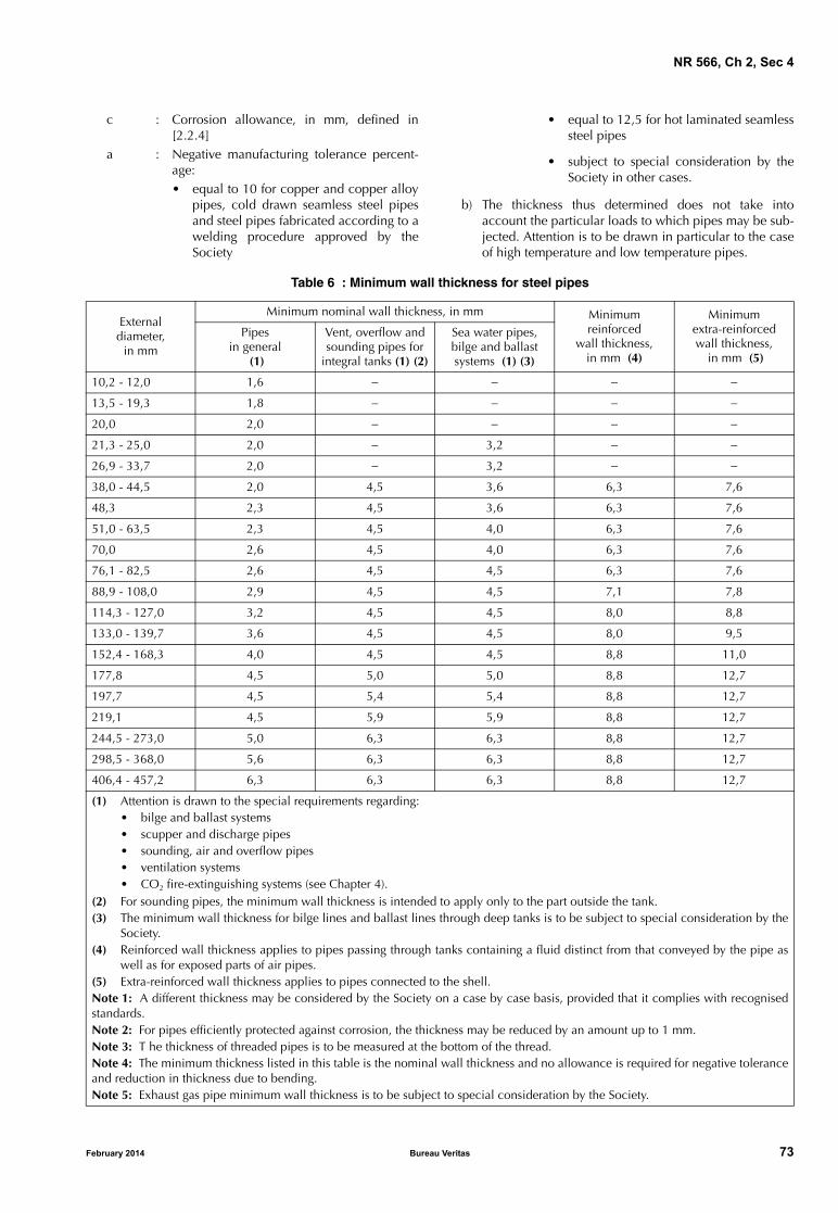
NR 566, Ch 2, Sec 4
c : Corrosion allowance, in mm, defined in[2.2.4]
a : Negative manufacturing tolerance percent-age:• equal to 10 for copper and copper alloy
pipes, cold drawn seamless steel pipesand steel pipes fabricated according to awelding procedure approved by theSociety
February 2014 Bureau Ve
• equal to 12,5 for hot laminated seamlesssteel pipes
• subject to special consideration by theSociety in other cases.
b) The thickness thus determined does not take intoaccount the particular loads to which pipes may be sub-jected. Attention is to be drawn in particular to the caseof high temperature and low temperature pipes.
Table 6 : Minimum wall thickness for steel pipes
Externaldiameter,
in mm
Minimum nominal wall thickness, in mm Minimum reinforced
wall thickness,in mm (4)
Minimumextra-reinforced wall thickness,
in mm (5)
Pipesin general
(1)
Vent, overflow and sounding pipes for
integral tanks (1) (2)
Sea water pipes, bilge and ballast systems (1) (3)
10,2 - 12,0 1,6 − − − −
13,5 - 19,3 1,8 − − − −
20,0 2,0 − − − −
21,3 - 25,0 2,0 − 3,2 − −
26,9 - 33,7 2,0 − 3,2 − −
38,0 - 44,5 2,0 4,5 3,6 6,3 7,6
48,3 2,3 4,5 3,6 6,3 7,6
51,0 - 63,5 2,3 4,5 4,0 6,3 7,6
70,0 2,6 4,5 4,0 6,3 7,6
76,1 - 82,5 2,6 4,5 4,5 6,3 7,6
88,9 - 108,0 2,9 4,5 4,5 7,1 7,8
114,3 - 127,0 3,2 4,5 4,5 8,0 8,8
133,0 - 139,7 3,6 4,5 4,5 8,0 9,5
152,4 - 168,3 4,0 4,5 4,5 8,8 11,0
177,8 4,5 5,0 5,0 8,8 12,7
197,7 4,5 5,4 5,4 8,8 12,7
219,1 4,5 5,9 5,9 8,8 12,7
244,5 - 273,0 5,0 6,3 6,3 8,8 12,7
298,5 - 368,0 5,6 6,3 6,3 8,8 12,7
406,4 - 457,2 6,3 6,3 6,3 8,8 12,7
(1) Attention is drawn to the special requirements regarding:• bilge and ballast systems• scupper and discharge pipes• sounding, air and overflow pipes• ventilation systems• CO2 fire-extinguishing systems (see Chapter 4).
(2) For sounding pipes, the minimum wall thickness is intended to apply only to the part outside the tank.(3) The minimum wall thickness for bilge lines and ballast lines through deep tanks is to be subject to special consideration by the
Society. (4) Reinforced wall thickness applies to pipes passing through tanks containing a fluid distinct from that conveyed by the pipe as
well as for exposed parts of air pipes.(5) Extra-reinforced wall thickness applies to pipes connected to the shell. Note 1: A different thickness may be considered by the Society on a case by case basis, provided that it complies with recognisedstandards.Note 2: For pipes efficiently protected against corrosion, the thickness may be reduced by an amount up to 1 mm.Note 3: T he thickness of threaded pipes is to be measured at the bottom of the thread.Note 4: The minimum thickness listed in this table is the nominal wall thickness and no allowance is required for negative toleranceand reduction in thickness due to bending.Note 5: Exhaust gas pipe minimum wall thickness is to be subject to special consideration by the Society.
ritas 73

NR 566, Ch 2, Sec 4
Table 7 : Minimum wall thicknessfor copper and copper alloy pipes
2.2.2 Permissible stress
a) The permissible stress K is given:
• in Tab 10 for carbon and carbon-manganese steelpipes
• in Tab 11 for alloy steel pipes, and
• in Tab 12 for copper and copper alloy pipes
as a function of the temperature. Intermediate valuesmay be obtained by interpolation.
b) Where, for carbon steel and alloy steel pipes, the valueof the permissible stress K is not given in Tab 10 or Tab11, it is to be taken equal to the lowest of the followingvalues:
where:
Rm,20 : Minimum tensile strength of the material atambient temperature (20°C), in N/mm2
Re : Minimum yield strength or 0,2% proof stressat the design temperature, in N/mm2
SR : Average stress to produce rupture in 100000h at design temperature, in N/mm2
S : Average stress to produce 1% creep in100000 h at design temperature, in N/mm2
A : Safety factor to be taken equal to:
• 1,6 when Re and SR values result fromtests attended by the Society
• 1,8 otherwise
c) The permissible stress values adopted for materials otherthan carbon steel, alloy steel, copper and copper alloyis to be specially considered by the Society.
External diameter, in mmMinimum wall thickness, in mm
Copper Copper alloy
8 - 10 1,0 0,8
12 - 20 1,2 1,0
25 - 44,5 1,5 1,2
50 - 76,1 2,0 1,5
88,9 - 108 2,5 2,0
133 - 159 3,0 2,5
193,7 - 267 3,5 3,0
273-457,2 4,0 3,5
470 4,0 3,5
508 4,5 4,0
Note 1: The indicated values are valid for pipes in general,sea water pipes and vent, overflow and sounding pipes.When reinforced or extra-reinforced wall thicknesses arerequired, the values of, respectively, the first and secondrows below are to be considered.Note 2: A different thickness may be considered by the Soci-ety on a case-by-case basis, provided that it complies withrecognised standards.
Rm 20,
2 7,----------- Re
A----- SR
A----- S
74 Bureau Ve
Table 8 : Minimum wall thicknessfor austenitic stainless steel pipes
Table 9 : Minimum wall thicknessfor aluminium and aluminium alloy pipes
Table 10 : Permissible stress Kfor carbon and carbon-manganese steel pipes
External diameter, in mm Minimum wall thickness, in mm
10,2 - 17,2 1,0
21,3 - 48,3 1,6
60,3 - 88,9 2,0
114,3 - 168,3 2,3
219,1 2,6
273,0 2,9
323,9 - 406,4 3,6
over 406,4 4,0
Note 1: The indicated values are valid for pipes in general,sea water pipes and vent, overflow and sounding pipes.When reinforced or extra-reinforced wall thicknesses arerequired, the values of, respectively, the first and secondrows below are to be considered.Note 2: Diameters and thicknesses according to national orinternational standards may be accepted.
External diameter, in mm Minimum wall thickness, in mm
0 - 10 1,5
12 - 38 2,0
43 - 57 2,5
76 - 89 3,0
108 - 133 4,0
159 - 194 4,5
219 - 273 5,0
above 273 5,5
Note 1: The indicated values are valid for pipes in general,sea water pipes and vent, overflow and sounding pipes.When reinforced or extra-reinforced wall thicknesses arerequired, the values of, respectively, the first and secondraws below are to be considered.Note 2: A different thickness may be considered by the Soci-ety on a case-by-case basis, provided that it complies withrecognised standards.
Specified minimum tensile strength,
in N/mm2
Design temperature, in °C
≤50 100 150 200
320 107 105 99 92
360 120 117 110 103
410 136 131 124 117
460 151 146 139 132
490 160 156 148 141
ritas February 2014

NR 566, Ch 2, Sec 4
Table 11 : Permissible stress K for alloy steel pipes
Table 12 : Permissible stress K for copper and copper alloy pipes
Type of steelSpecified minimum tensile
strength, in N/mm2
Design temperature, in °C
≤50 100 200
1Cr1/2Mo 440 159 150 137
2 1/4Cr1Mo annealed 410 76 67 57
2 1/4Cr1Mo normalised and tempered below 750°C 490 167 163 153
2 1/4Cr1Mo normalized and tempered above 750°C 490 167 163 153
1/2Cr 1/2Mo 1/4V 460 166 162 147
Material (annealed)Specified minimum tensile
strength, in N/mm2
Design temperature, in °C
≤50 75 100 125 150 175 200
Copper 215 41 41 40 40 34 27,5 18,5
Aluminium brass 325 78 78 78 78 78 51 24,5
Copper-nickel 95/5 and 90/10 275 68 68 67 65,5 64 62 59
Copper-nickel 70/30 365 81 79 77 75 73 71 69
2.2.3 Thickness reduction due to bending
a) Unless otherwise justified, the thickness reduction b dueto bending is to be determined by the following for-mula:
where:
ρ : Bending radius measured on the centre lineof the pipe, in mm
D : As defined in [1.4.1]
t0 : As defined in [2.2.1].
b) When the bending radius is not given, the thicknessreduction is to be taken equal to t0 / 10
c) For straight pipes, the thickness reduction is to be takenequal to 0.
Table 13 : Corrosion allowance for steel pipes
Piping system Corrosion allowance, in mm
Compressed air 1,0
Hydraulic oil 0,3
Lubricating oil 0,3
Fuel oil 1,0
Fresh water 0,8
Sea water 3,0
Note 1: For pipes passing through tanks, an additional corro-sion allowance is to be considered in order to account forthe external corrosion.Note 2: The corrosion allowance of pipes efficiently pro-tected against corrosion may be reduced by no more than50%.Note 3: When the corrosion resistance of alloy steels is ade-quately demonstrated, the corrosion allowance may be dis-regarded.
bDt0
2 5ρ,------------=
February 2014 Bureau Ve
2.2.4 Corrosion allowanceThe values of corrosion allowance c are given for steel pipesin Tab 13 and for non-ferrous metallic pipes in Tab 14.
2.2.5 TeesAs well as complying with the provisions of [2.2.1] to[2.2.4], the thickness tT of pipes on which a branch iswelded to form a Tee is not to be less than that given by thefollowing formula:
where:
D1 : External diameter of the branch pipeD : As defined in [1.4.1]
t0 : As defined in [2.2.1].Note 1: This requirement may be dispensed with for Tees providedwith a reinforcement or extruded.
Table 14 : Corrosion allowance for non-ferrous metal pipes
Piping material (1)Corrosion allowance, in mm (2)
Copper 0,8
Brass 0,8
Copper-tin alloys 0,8
Copper-nickel alloys with less than 10% of Ni 0,8
Copper-nickel alloys with at least 10% of Ni 0,5
Aluminium and aluminium alloys 0,5
(1) The corrosion allowance for other materials is to bespecially considered by the Society. Where their resist-ance to corrosion is adequately demonstrated, the cor-rosion allowance may be disregarded.
(2) In cases of media with high corrosive action, a highercorrosion allowance may be required by the Society.
tT 1D1
D------+
t0⋅=
ritas 75

NR 566, Ch 2, Sec 4
Table 15 : Use of welded and threaded metallic joints in piping systems
JointsPermitted
classes of pipingRestrictions of use
Butt-welded, with special provision fora high quality of root side (1)
III, II, I no restrictions
Butt-welded, without special provisionfor a high quality of root side (1)
III, II no restrictions
Slip-on sleeve and socket welded (2) III no restrictions
Threaded sleeve joints with taperedthread (3)
I not allowed for:• pipes with outside diameter of more than 33,7 mm• pipes inside tanks• piping systems conveying flammable media or services where
fatigue, severe erosion or crevice corrosion is expected to occur.
III, II not allowed for:• pipes with outside diameter of more than 60,3 mm• pipes inside tanks• piping systems conveying flammable media or services where
fatigue, severe erosion or crevice corrosion is expected to occur.
Threaded sleeve joints with parallelthread (3)
III not allowed for:• pipes with outside diameter of more than 60,3 mm• pipes inside tanks• piping systems conveying flammable media or services where
fatigue, severe erosion or crevice corrosion is expected to occur.
(1) For expression “special provision for a high quality of root side” see [2.3.2], item b).(2) Particular cases may be allowed by the Society for piping systems of Class I and II having outside diameter ≤ 88,9 mm except for
piping systems conveying toxic media or services where fatigue, severe erosion or crevice corrosion is expected to occur.(3) In particular cases, sizes in excess of those mentioned above may be accepted by the Society if they are found in compliance
with a recognised national and/or international standard.Note 1: Other applications are to be specially considered by the Society.
2.3 Junction of metallic pipes
2.3.1 General
a) The junctions between metallic pipe lengths or betweenmetallic pipe lengths and fittings are to be made by:
• direct welding (butt-weld, socket-weld)
• bolted flanges (welded-on or screwed-on)
• threaded sleeve joints, or
• mechanical joints (see [2.3.5]).
The joints are to comply with a recognised standard orto be of a design proven to be suitable for the intendedpurpose and acceptable to the Society. See also [2.4.1].
The expression "mechanical joints" means devicesintended for direct connection of pipe lengths otherthan by welding, flanges or threaded joints described in[2.3.2], [2.3.3] or [2.3.4].
b) The number of joints in flammable oil piping systems isto be kept to the minimum necessary for mounting anddismantling purposes.
c) The gaskets and packings used for the joints are to suitthe design pressure, the design temperature and thenature of the fluids conveyed.
d) The junction between plastic pipes is to comply with [3].
76 Bureau Ve
2.3.2 Welded metallic joints
a) Welded joints are to be used in accordance with Tab 15.Welding and non destructive testing of welds are to becarried out in accordance with [2.4.1].
b) Butt-welded joints are to be of full penetration type,with or without special provision for a high quality ofroot side.
The expression "special provision for a high quality ofroot side" means that butt welds were accomplished asdouble welded or by use of a backing ring or inert gasback-up on first pass, or other similar methods acceptedby the Society.
c) Slip-on sleeve and socket welded joints are to havesleeves, sockets and weldments of adequate dimensionsin compliance with a standard recognised by the Soci-ety.
2.3.3 Metallic flange connections
a) In general, the metallic flange connections used for pip-ing systems are to be in compliance with a standard rec-ognised by the Society.
b) The material used for flanges and gaskets is to be suita-ble for the nature and temperature of the fluid, as wellas pipes on which the flanges are to be fitted.
ritas February 2014
NR 566, Ch 2, Sec 4
c) The dimensions and configuration of flanges and boltsare to be chosen in accordance with recognised stand-ard intended for design pressure and design temperatureof the piping system. Otherwise, the flange connectionsare subject to special consideration.
d) Flanges are to be attached to the pipes by welding orscrewing. Examples of acceptable metallic flange con-nections are shown in Fig 1. However, other types offlange connections may be also considered by the Soci-ety in each particular case, provided that they are inaccordance with national or international standardsapplicable to the piping system and recognise theboundary fluids, design pressure and temperature con-ditions, external or cyclic loading and location.
e) Permitted applications are indicated in Tab 16.
2.3.4 Slip-on threaded joints
a) Slip-on threaded joints having pipe threads where pres-sure-tight joints are made on the threads with parallel ortapered threads are to comply with requirements of arecognised national or international standard and are tobe acceptable to the Society.
b) Slip-on threaded joints may be used for piping systemsin accordance with Tab 15.
c) Threaded joints may be accepted also in CO2 pipingsystems, provided that they are used only inside pro-tected spaces and in CO2 cylinder rooms.
2.3.5 Mechanical joints
Due to the great variations in design and configuration ofmechanical joints, specific recommendation regarding cal-culation method for theoretical strength calculations is notspecified. The Type Approval is to be based on the results oftesting of the actual joints.
Below specified requirements are applicable to pipeunions, compression couplings, slip-on joints as shown inFig 2. Similar joints complying with these requirements maybe acceptable.
a) Mechanical joints including pipe unions, compressioncouplings, slip-on joints and similar joints are to be ofapproved type for the service conditions and theintended application.
b) Where the application of mechanical joints results inreduction in pipe wall thickness due to the use of bitetype rings or other structural elements, this is to be takeninto account in determining the minimum wall thick-ness of the pipe to withstand the design pressure.
c) Construction of mechanical joints is to prevent the pos-sibility of tightness failure affected by pressure pulsa-tion, piping vibration, temperature variation and othersimilar adverse effects occurring during operation onboard.
d) Material of mechanical joints is to be compatible withthe piping material and internal and external media.
e) As far as applicable, the mechanical joints are to betested to a burst pressure of 4 times the design pressure.
February 2014 Bureau Ve
For design pressures above 200 bar the required burstpressure is to be specially considered by the Society.
f) In general, mechanical joints are to be of fire resistanttype as required by Tab 17.
g) Mechanical joints, which in the event of damage couldcause fire or flooding, are not to be used in piping sec-tions directly connected to the shell openings or tankscontaining flammable fluids.
h) The mechanical joints are to be designed to withstandinternal and external pressure as applicable and, whereused in suction lines, are to be capable of operatingunder vacuum.
i) The number of mechanical joints in flammable liquidsystems is to be kept to a minimum. In general, flangedjoints conforming to recognised standards are to beused.
j) Piping in which a mechanical joint is fitted is to be ade-quately adjusted, aligned and supported. Supports orhangers are not to be used to force alignment of pipingat the point of connection.
k) Slip-on joints are not to be used in pipelines in cargoholds, tanks, and other spaces which are not easilyaccessible, unless approved by the Society. Applicationof these joints inside tanks may be permitted only for thesame media that is in the tanks. Unrestrained slip-onjoints are to be used only in cases where compensationof lateral pipe deformation is necessary. Usage of thesejoints as the main means of pipe connection is not per-mitted.
l) Application of mechanical joints and their acceptableuse for each service is indicated in Tab 17; dependenceupon the class of piping, pipe dimensions, workingpressure and temperature is indicated in Tab 18.
m) In some particular cases, sizes in excess of those men-tioned above may be accepted by the Society if they arein compliance with a recognised national and/or inter-national standard.
n) Application of various mechanical joints may beaccepted as indicated by Tab 17. However, in all cases,acceptance of the joint type is to be subject to approvalfor the intended application, and subject to conditionsof the approval and applicable Rules.
o) Mechanical joints are to be tested in accordance with aprogram approved by the Society, which is to include atleast the following:
1) leakage test
2) vacuum test (where necessary)
3) vibration (fatigue) test
4) fire endurance test (where necessary)
5) burst pressure test
6) pressure pulsation test (where necessary)
7) assembly test (where necessary)
8) pull out test (where necessary).
ritas 77

NR 566, Ch 2, Sec 4
Figure 1 : Examples of metallic flange connections
Note 1: For type D, the pipe and flange are to be screwed with a tapered thread and the diameter of the screw portion of the pipe over thethread is not to be appreciably less than the outside diameter of the unthreaded pipe. For certain types of thread, after the flange has beenscrewed hard home, the pipe is to be expanded into the flange.
Note 2: The leg length of the fillet weld, as well as the dimension of the groove penetration in the flange, is to be in general equal to 1,5 timesthe pipe thickness but not less than 5 mm.
���� ��
���� �� ���� �
���� � ���� �
���� �� ���� � ���� �
���� �
���� � ����
78 Bureau Veritas February 2014

NR 566, Ch 2, Sec 4
Table 16 : Use of metallic flange connections in piping systems (types as shown in Fig 1)
Figure 2 : Examples of mechanical joints
Type of media conveyedClass of piping (see Tab 3)
I II III
Flammable liquids (where heated aboveflashpoint or having flashpoint < 60°C
A1, A2, B1, B2, B3 (1) (2)
A1, A2, B1, B2, B3, C1, C2, C3 (1)
not applicable
Fuel oilLubricating oil
A1, A2, B1, B2, B3 A1, A2, B1, B2, B3, C1, C2, C3
A1, A2, B1, B2, B3, C1, C2, C3, E2
Other media as water, air, gases (refrigerants), non-flammable hydraulic oil, etc.
A1, A2, B1, B2, B3 (4) A1, A2, B1, B2, B3, C1, C2, C3, D, E2 (5)
A1, A2, B1, B2, B3, C1, C2, C3, D, E1, E2 (3) (5) (6)
(1) When design pressure p (see [1.3.2]) exceeds 1 MPa, types A1 and A2 only.(2) For nominal diameter ND ≥ 150 mm, types A1 and A2 only.(3) Type E2 only, for design pressure p ≤ 1,6 Mpa and design temperature T ≤ 150°C.(4) When design temperature T (see [1.3.3]) exceeds 400°C, types A1 and A2 only.(5) Types D and E1 only, for design temperature T ≤ 250°C.(6) Type E1 only, for water pipelines and for open ended lines (e.g. drain, overflow, air vent piping, etc.).
���� �����
������ ��� ���� �� ��
�������� � �����
����� �� � ���� �� �
���� �� � ����� �� �
������� �����
�� �� � ������� ������ �� �
��� �� ��
February 2014 Bureau Veritas 79
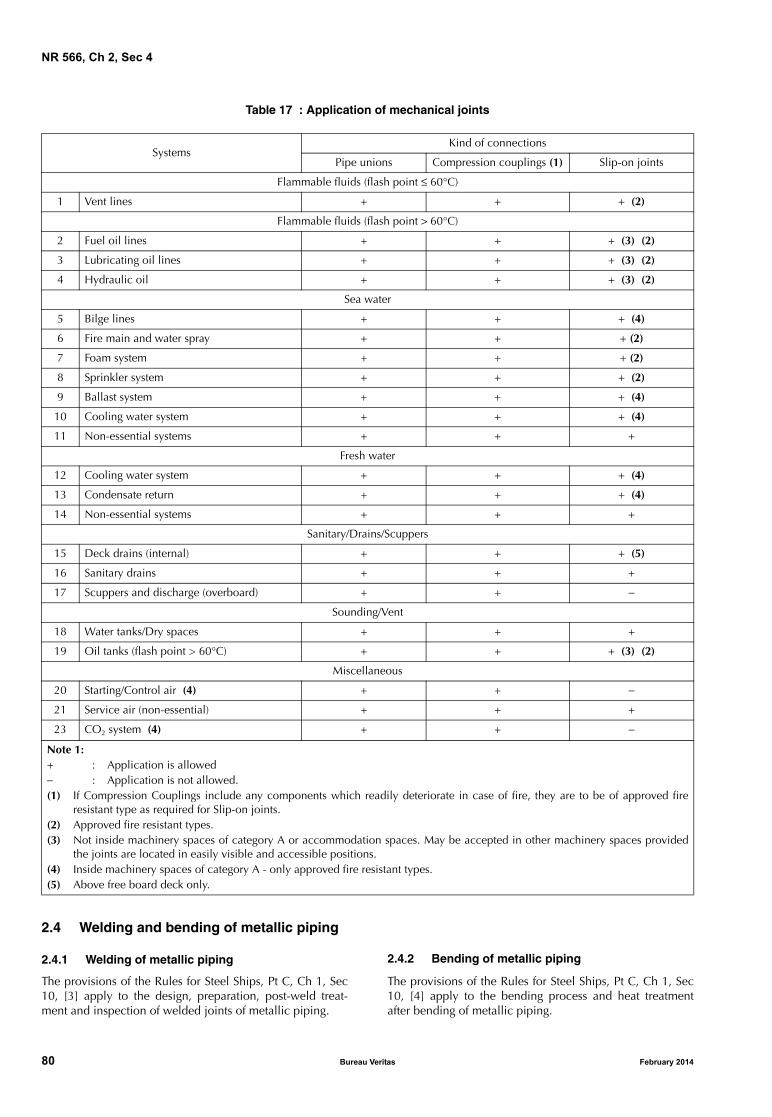
NR 566, Ch 2, Sec 4
Table 17 : Application of mechanical joints
SystemsKind of connections
Pipe unions Compression couplings (1) Slip-on joints
Flammable fluids (flash point ≤ 60°C)
1 Vent lines + + + (2)
Flammable fluids (flash point > 60°C)
2 Fuel oil lines + + + (3) (2)
3 Lubricating oil lines + + + (3) (2)
4 Hydraulic oil + + + (3) (2)
Sea water
5 Bilge lines + + + (4)
6 Fire main and water spray + + + (2)
7 Foam system + + + (2)
8 Sprinkler system + + + (2)
9 Ballast system + + + (4)
10 Cooling water system + + + (4)
11 Non-essential systems + + +
Fresh water
12 Cooling water system + + + (4)
13 Condensate return + + + (4)
14 Non-essential systems + + +
Sanitary/Drains/Scuppers
15 Deck drains (internal) + + + (5)
16 Sanitary drains + + +
17 Scuppers and discharge (overboard) + + −
Sounding/Vent
18 Water tanks/Dry spaces + + +
19 Oil tanks (flash point > 60°C) + + + (3) (2)
Miscellaneous
20 Starting/Control air (4) + + −
21 Service air (non-essential) + + +
23 CO2 system (4) + + −
Note 1: + : Application is allowed− : Application is not allowed.(1) If Compression Couplings include any components which readily deteriorate in case of fire, they are to be of approved fire
resistant type as required for Slip-on joints.(2) Approved fire resistant types.(3) Not inside machinery spaces of category A or accommodation spaces. May be accepted in other machinery spaces provided
the joints are located in easily visible and accessible positions.(4) Inside machinery spaces of category A - only approved fire resistant types.(5) Above free board deck only.
2.4 Welding and bending of metallic piping
2.4.1 Welding of metallic piping
The provisions of the Rules for Steel Ships, Pt C, Ch 1, Sec10, [3] apply to the design, preparation, post-weld treat-ment and inspection of welded joints of metallic piping.
80 Bureau Ve
2.4.2 Bending of metallic piping
The provisions of the Rules for Steel Ships, Pt C, Ch 1, Sec10, [4] apply to the bending process and heat treatmentafter bending of metallic piping.
ritas February 2014

NR 566, Ch 2, Sec 4
Table 18 : Application of mechanical joints depending upon the class of piping
Types of jointsClasses of piping systems
Class I Class II Class III
Pipe Unions
Welded and brazed types + (OD ≤ 60,3 mm) + (OD ≤ 60,3 mm) +
Compression Couplings
Swage type + + +
Bite typeFlared type
+ (OD ≤ 60,3 mm)+ (OD ≤ 60,3 mm)
+ (OD ≤ 60,3 mm)+ (OD ≤ 60,3 mm)
++
Press type − − +
Slip-on Joints
Machine grooved type + + +
Grip type − + +
Slip type − + +
Note 1:+ : Application is allowed− : Application is not allowed.
3 Design of plastic piping systems
3.1 General
3.1.1 ApplicationThese requirements are applicable to all piping systemswith parts made of rigid plastic.
3.1.2 Use of plastic pipesPlastic may be used in piping systems in accordance withthe provisions of Tab 5, provided the following require-ments are complied with.
3.1.3 Type approvalPlastic piping used for essential services and if used in cir-cuits where in case of damage of the pipe the safety of theship is impaired are to be type approved.
3.1.4 MarkingPlastic pipes and fittings are to be permanently marked withidentification, including:
• pressure ratings
• the design standards that the pipe or fitting is manufac-tured in accordance with
• the material of which the pipe or fitting is made.
3.2 Definitions
3.2.1 PlasticPlastic includes both thermoplastic and thermosetting plas-tic materials with or without reinforcement, such as PVCand FRP (reinforced plastics pipes).
3.2.2 Piping systemsPiping systems include the pipes, fittings, joints, and anyinternal or external liners, coverings and coatings requiredto comply with the performance criteria.
February 2014 Bureau Ve
3.2.3 JointsJoints include all pipe assembling devices or methods, suchas adhesive bonding, laminating, welding, etc.
3.2.4 FittingsFittings include bends, elbows, fabricated branch pieces,etc. made of plastic materials.
3.2.5 Nominal pressureNominal pressure is the maximum permissible workingpressure which is to be determined in accordance with[3.3.3].
3.2.6 Fire enduranceFire endurance is the capability of the piping system to per-form its intended function, i.e. maintain its strength andintegrity, for some predicted period of time while exposedto fire. The indication L3, used in Tab 5, refers to a 30 minfire endurance test in wet conditions in accordance withIMO Res. A753(18).
3.3 Strength
3.3.1 General
a) The piping is to have sufficient strength to take accountof the most severe concomitant conditions of pressure,temperature, the weight of the piping itself and anystatic and dynamic loads imposed by the design or envi-ronment.
b) The strength of the pipes is to be determined at the max-imum possible working temperature by the tests men-tioned in [3.7.1].
3.3.2 Pipe thicknessPlastic pipes thickness is to be calculated using a maximumallowable stress not higher than 1/7 of the ultimate tensilestrength of the material at the service temperature.
ritas 81

NR 566, Ch 2, Sec 4
3.3.3 Permissible pressurePiping systems are to be designed for a nominal pressuredetermined from the following conditions:
a) Internal pressure
The nominal internal pressure is not to exceed thesmaller of:
• Psth / 4
• Plth / 2,5
where:
Psth : Short-term hydrostatic test failure pressure,in MPa
Plth : Long-term hydrostatic test failure pressure(>100 000 hours), in MPa.
b) External pressure (to be considered for any installationsubject to vacuum conditions inside the pipe or a headof liquid acting on the outside of the pipe)
The nominal external pressure is not to exceed Pcol / 3,where:
Pcol : Collapse pressure.Note 1: The external pressure is the sum of the vacuum inside the
pipe and the static pressure head outside the pipe.
c) The collapse pressure is not to be less than 0,3 MPa.
3.3.4 Permissible temperature
a) In general, plastic pipes are not to be used for mediawith a temperature above 60°C or below 0°C, unlesssatisfactory justification is provided to the Society.
b) The permissible working temperature range depends onthe working pressure and is to be justified by appropri-ate tests.
c) The maximum permissible working temperature is to beat least 20°C lower than the minimum heat distortiontemperature of the pipe material, determined accordingto ISO 75 method A or equivalent.
d) The minimum heat distortion temperature is not to beless than 80°C.
3.3.5 Axial strength
a) The sum of the longitudinal stresses due to pressure,weight and other loads is not to exceed the allowablestress in the longitudinal direction.
b) In the case of fibre reinforced plastic pipes, the sum ofthe longitudinal stresses is not to exceed half of thenominal circumferential stress derived from the nominalinternal pressure condition (see [3.3.3]).
3.3.6 Impact resistancePlastic pipes and joints are to have a minimum resistance toimpact in accordance with a recognised national or interna-tional standard.
3.4 Fire safety characteristics
3.4.1 Fire enduranceThe indication L3, used in Tab 5, refers to a 30 min fireendurance testing under wet conditions in accordance withIMO Res.A753(18).
82 Bureau Ve
3.4.2 Flame spread
The following applies for passenger vessels having naviga-tion notation coastal area and carrying more than 50 pas-sengers:
a) All pipes, except those fitted on open decks and withintanks, cofferdams, pipe tunnels and ducts, are to havelow spread characteristics not exceeding average valueslisted in IMO Resolution A.653(16). Other recognisednational standards may also be referred to.
b) Surface flame characteristics are to be determined usingthe procedure given in IMO Res. A.653(16) with regardto the modifications due to the curvilinear pipe surfacesas listed in Appendix 3 of Res. A.753(18).
3.4.3 Fire protection coating
Where a fire protective coating of pipes and fittings is nec-essary for achieving the fire endurance level required, it isto meet the following requirements:
• The pipes are generally to be delivered from the manu-facturer with the protective coating on
• The fire protection properties of the coating are not to bediminished when exposed to salt water, oil or bilgeslops. It is to be demonstrated that the coating is resistantto products likely to come into contact with the piping
• In considering fire protection coatings, such characteris-tics as thermal expansion, resistance against vibrationsand elasticity are to be taken into account
• The fire protection coatings are to have sufficient resist-ance to impact to retain their integrity.
3.4.4 Electrical conductivity
a) Piping systems conveying fluids with a conductivity lessthan 1000 pS/m (1 pS/m = 10−9 siemens per meter), suchas refined products and distillates, are to be made ofconductive pipes.
b) Regardless of the fluid to be conveyed, plastic pipespassing through hazardous areas are to be electricallyconductive.
c) Where electrical conductivity is to be ensured, theresistance of the pipes and fittings is not to exceed:1⋅105 Ohm/m.
d) Where pipes and fittings are not homogeneously con-ductive, conductive layers are to be provided, suitablyprotected against the possibility of spark damage to thepipe wall.
3.5 Pipe and fitting connections
3.5.1 General
a) The strength of connections is not to be less than that ofthe piping system in which they are installed.
b) Pipes and fittings may be assembled using adhesive-bonded, welded, flanged or other joints.
c) When used for joint assembly, adhesives are to be suita-ble for providing a permanent seal between the pipesand fittings throughout the temperature and pressurerange of the intended application.
ritas February 2014
NR 566, Ch 2, Sec 4
d) Tightening of joints, where required, is to be performedin accordance with the manufacturer’s instructions.
e) Procedures adopted for pipe and fitting connections areto be submitted to the Society for approval, prior tocommencing the work.
3.5.2 Bonding of pipes and fittings
a) The procedure for making bonds is to be submitted tothe Society for qualification. It is to include the follow-ing:
• materials used
• tools and fixtures
• joint preparation requirements
• cure temperature
• dimensional requirements and tolerances
• acceptance criteria for the test of the completedassembly.
b) When a change in the bonding procedure may affect thephysical and mechanical properties of the joints, theprocedure is to be requalified.
3.6 Arrangement and installation of plastic pipes
3.6.1 GeneralPlastic pipes and fittings are to be installed by the Shipyardin accordance with the Manufacturer’s guidelines and takingaccount of the following provisions, as deemed necessary.
3.6.2 Supporting of pipes
a) Selection and spacing of pipe supports in shipboard sys-tems are to be determined as a function of allowablestresses and maximum deflection criteria.
b) The selection and spacing of pipe supports are to takeinto account the following data:
• pipe dimensions
• mechanical and physical properties of the pipematerial
• mass of pipe and contained fluid
• external pressure
• operating temperature
• thermal expansion effects
• load due to external forces
• thrust forces
• water hammer
• vibrations
• maximum accelerations to which the system may besubjected.
Combinations of loads are also to be considered.
c) Support spacing is not to be greater than the pipe man-ufacturer’s recommended spacing.
d) Each support is to evenly distribute the load of the pipeand its content over the full width of the support. Meas-ures are to be taken to minimise wear of the pipeswhere they are in contact with the supports.
February 2014 Bureau Ve
e) Heavy components in the piping system such as valvesand expansion joints are to be independently supported.
3.6.3 Provisions for expansion
a) Suitable provision is to be made in each pipeline toallow for relative movement between pipes made ofplastic and the steel structure, having due regard to:
• the high difference in the coefficients of thermalexpansion
• deformations of the ship’s structure.
b) Calculations of the thermal expansions are to take intoaccount the system working temperature and the tem-perature at which the assembly is performed.
3.6.4 Provisions of mechanical damage
a) When installing the piping, allowance is to be made fortemporary point loads, where applicable. Such allow-ance is to include at least the force exerted by a load(person) of 100 kg at mid-span on any pipe of more than100 mm nominal outside diameter.
b) Pipes are to be protected from mechanical damagewhere necessary.
3.6.5 Earthing
a) Where, in pursuance of [3.4.4], pipes are required to beelectrically conductive, the resistance to earth from anypoint in the piping system is not to exceed 1 x 10⁶ Ω.
b) Where provided, earthing wires are to be accessible forinspection.
3.6.6 Penetration of fire divisions and watertight bulkheads or decks
a) Where plastic pipes pass through “A” or “B” class divi-sions, arrangements are to be made to ensure that fireendurance is not impaired. These arrangements are tobe tested in accordance with ‘Recommendations forFire Test Procedures for “A”, “B” and “F” Bulkheads’(IMO Resolution A754 (18) as amended).
b) When plastic pipes pass through watertight bulkheadsor decks, the watertight integrity of the bulkhead or deckis to be maintained. If the bulkhead or deck is also a firedivision and destruction by fire of plastic pipes maycause the inflow of liquid from tanks, a metallic shut-offvalve operable from above the freeboard deck is to befitted at the bulkhead or deck.
3.7 Certification
3.7.1 Type approval
The requirements for testing, inspection and certification inthe scope of type approval of plastic piping are indicated inthe Rules for Steel Ships, Pt C, Ch 1, App 3, [4].
3.7.2 Workshop tests
Each pipe and fitting is to be tested by the manufacturer at ahydrostatic pressure not less than 1,5 times the nominalpressure.
ritas 83
NR 566, Ch 2, Sec 4
3.7.3 Testing after installation on board
a) Piping systems for essential systems are to be subjectedto a hydrostatic test pressure of not less than 1,5 timesthe design pressure or 0,4 MPa, whichever is the greater.
b) Piping systems for non-essential services are to bechecked for leakage under operational conditions.
c) For piping required to be electrically conductive, earth-ing is to be checked and random resistance testing is tobe performed.
4 Design of flexible piping systems
4.1 General
4.1.1 Definition
Flexible piping are not metallic flexible pipes which areused for not limited lengths in piping systems as a replace-ment of metallic or plastic rigid piping as defined in [2] and[3]. No confusion is to made with flexible hoses and expan-sion joints as defined in [5.3.1].
4.1.2 Documentation
a) The drawings of the flexible piping are to be submitted tothe Society. These drawings are to indicate in particular:
• the manufacturer and the type
• the composition
• the physical and mechanical characteristics accord-ing to the temperature
• the characteristics of inflammability and the fireresistance
• eventually the resistance to the various productsthey are likely to come into contact with
• the diameter and thickness
• the type of junctions with the other pipes and fit-tings.
b) Flexible piping is to undergo type-tests defined in[4.2.4].
4.2 Design
4.2.1 Design - Construction
a) Flexible pipes are to be made of materials resisting tomarine environment and to the fluid they are to convey.
b) Flexible pipes are to be designed so as to withstand:
• externally to hydrocarbons
• to internal pressure
• to vibrations.
c) Flexible pipes intended to convey oil or fuel are to befire-resistant. Where a protective lining is provided forthis purpose, it is to be impervious to hydrocarbons andhydrocarbon vapours.
d) If flexible pipes are intended to be fitted at pump suc-tions, in particular bilge pumps, they are to be sodesigned as to avoid any risk of collapsing due to theinternal depression of the pipes.
84 Bureau Ve
e) Clips made of corrosion-resistant material may be usedfor the junction of flexible piping, with at least two clipsat each end, except for oil and fuel circuits wherecrimped connections are to be used.
f) The bursting pressure of non-metallic hoses is not to beless than four times their maximum service pressure.
4.2.2 Conditions of use
a) Flexible piping may be used in accordance with theprovisions of [1.6.4].
b) The position of the flexible piping is to be clearly shownon the piping drawings submitted to the Society.
c) Isolating valves are to be provided permitting the isola-tion of flexible pipes intended to convey fuel, oil orcompressed air.
d) Flexible piping is not to be used between the ship's sidevalves and the ship side plating.
e) Flexible piping is not to be used for the part of bilge pip-ing circuits going through compartments intended tocontain oil fuel.
4.2.3 Installation
a) Flexible piping is to be so arranged as to be easilyaccessible.
b) They have to be supported by means of collars or similardevices, so that the hoses and the junctions are not sub-mitted to excessive stresses in all the normal serviceconditions.
c) The parts of flexible piping which are likely to undergoshocks or frictions are to be adequately protected bymeans of shield or appropriate sleeve.
4.2.4 Type-tests
a) Each type of flexible pipe is to undergo:
• a bursting test
• an external hydrocarbon resistance test
• a fire resistance test in the cases mentioned in[4.2.1], item c)
• a collapse test in the cases mentioned in[4.2.1], item d)
• eventually vibration and ageing tests.
The tests are to be carried out on hoses having a signifi-cant length and fitted with connections as stated in[4.2.1], item e).
b) The fire resistance test is to be carried out in the follow-ing conditions; other test methods may apply after spe-cial examination.
The hose is to be submitted to fire for 30 minutes at atemperature of 800°C, while water at the maximumservice pressure is circulated inside the hose; the tem-perature of the water at the outlets is not to be less than80°C. No leak is to be recorded during and after the test.
c) Flexible pipes granted with a type approval certificateissued by the Society for the intended conditions of useare exempted from type-tests.
ritas February 2014

NR 566, Ch 2, Sec 4
4.2.5 Hydraulic tests
Each flexible pipe, together with its connections, is toundergo a hydraulic test under a pressure at least equal to1,5 times the maximum service pressure.
5 Arrangement and installation of piping systems
5.1 General
5.1.1 Unless otherwise specified, piping and pumping sys-tems covered by the Rules are to be permanently fixed onboard ship.
5.2 Protection against overpressure
5.2.1 General
a) These requirements deal with the protection of pipingsystems against overpressure, with the exception of heatexchangers and pressure vessels, which are dealt with inthe Rules for Steel Ships, Pt C, Ch 1, Sec 3.
b) Safety valves are to be sealed after setting.
5.2.2 Protection of flammable oil systems
Provisions are to be made to prevent overpressure in anyflammable oil tank or in any part of the flammable oil sys-tems, including the filling pipes.
5.2.3 Protection of pump and compressor discharges
a) Provisions are to be made so that the discharge pressureof pumps and compressors cannot exceed the pressurefor which the pipes located on the discharge of thesepumps and compressors are designed.
b) When provided on the pump discharge for this purpose,safety valves are to lead back to the pump suction or toany other suitable place.
c) The discharge capacity of the safety valves installed onpumps and compressors is to be such that the pressureat the discharge side cannot exceed by more than 10%the design pressure of the discharge pipe in the event ofoperation with closed discharge.
5.2.4 Protection of pipes
a) Pipes likely to be subjected to a pressure exceedingtheir normal working pressure are to be provided withsafety valves or equivalent overpressure protectingdevices.
b) In particular, pipes located on the low pressure side ofpressure reducing valves are to be provided with safetyvalves unless they are designed for the maximum pres-sure on the high pressure side of the pressure reducingvalve. See also [1.3.2] and [5.5.1].
c) The discharge capacity of the devices fitted on pipes forpreventing overpressure is to be such that the pressurein these pipes cannot exceed the design pressure bymore than 10%.
February 2014 Bureau Ve
5.3 Flexible hoses and expansion joints
5.3.1 DefinitionFlexible hoses and expansion joints are short flexible con-nection pieces between two parts of a piping system inorder to allow a relative movement between these parts.
5.3.2 Generala) The Society may permit the use of flexible hoses and
expansion joints, both in metallic and non-metallicmaterials, provided they are approved for the intendedservice.
b) Flexible hoses and expansion joints are to be of a typeapproved by the Society, designed in accordance with[5.3.4] and tested in accordance with [6.2.1].
c) Flexible hoses and expansion joints are to be installed inaccordance with the requirements stated in [5.3.6].
d) Flexible hoses and expansion joints intended for pipingsystems with a design temperature below the ambienttemperature will be given special consideration by theSociety.
5.3.3 DocumentationThe information, drawings and documentation listed in[1.2.1] and [1.2.2] are to be submitted to the Society foreach type of flexible hose or expansion joint intended to beused.
5.3.4 Design of flexible hoses and expansion jointsa) Flexible pipes and expansion joints are to be made of
materials resistant to the marine environment and to thefluid they are to convey. Metallic materials are to com-ply with [1.6].
b) Flexible pipes and expansion joints are to be designedso as to withstand:• external contact with hydrocarbons• internal pressure• vibrations• pressure impulses.
c) Flexible pipes intended to convey fuel oil or lubricatingoil and end attachments are to be of fire-resisting mate-rials of adequate strength and are to be constructed tothe satisfaction of the Society.Where a protective lining is provided for this purpose, itis to be impervious to hydrocarbons and to hydrocarbonvapours.
d) Flexible pipes intended to convey:• gaseous fluid at a pressure higher than 1 MPa• fuel oil or lubricating oil,are to be fitted with a metallic braid.
e) As a general rule, flexible hoses are to be fitted withcrimped connections or equivalent. For pipes subject toa pressure not exceeding 0,5 MPa, as well as for scav-enge air and supercharge air lines of internal combus-tion engines, clips made of galvanised steel orcorrosion-resistant material with thickness not less than0,4 mm may be used.For flexible piping of 25 mm diameter and above notless than two clips are to be fitted at each end.
ritas 85

NR 566, Ch 2, Sec 4
f) Flexible pipes and expansion joints are to be sodesigned that their bursting pressure at the service tem-perature is not less than 4 times their maximum servicepressure, with a minimum of 2 MPa. Exemptions fromthis requirement may be granted for expansion joints oflarge diameter used on sea water lines.
g) The junctions of flexible hoses and expansion joints totheir couplings are to withstand a pressure at least equalto the bursting pressure defined in item f).
h) Where necessary, non-metallic pipes and hoses are toshow a suitable resistance against collapse due to exter-nal pressure or bending.
5.3.5 Conditions of use of flexible hoses and expansion joints
a) The use of flexible hoses and expansion joints is to belimited as far as practicable.
b) The position of flexible hoses and expansion joints is tobe clearly shown on the piping drawings submitted tothe Society.
c) The use of non-metallic expansion joints on pipes con-nected to sea inlets and overboard discharges will begiven special consideration by the Society. As a rule, thefitting of such joints between the ship side and thevalves mentioned in [5.4.5] is not permitted. Further-more, unless the above-mentioned valves are fitted withremote controls operable from places located above thefreeboard deck, efficient means are to be provided,wherever necessary, to limit the flooding of the ship inthe event of rupture of the expansion joints.
d) Expansion joints may be fitted in sea water lines, pro-vided they are arranged with guards which effectivelyenclose, but do not interfere with, the action of theexpansion joints and reduce to the minimum practica-ble any flow of water into the machinery spaces in theevent of failure of the flexible elements.
e) Use of expansion joints in water lines for other services,including ballast lines in machinery spaces, in ductkeels and inside double bottom water ballast tanks, andbilge lines inside double bottom tanks and deep tanks,will be given special consideration by the Society.
5.3.6 Installation of flexible hoses and expansion joints
a) Flexible hoses and expansion joints are to be soarranged as to be accessible at all times.
b) Flexible hoses and expansion joints are to be as short aspossible.
c) The radius of curvature of flexible hoses is not to be lessthan the minimum recommended by the manufacturer.
d) The adjoining pipes are to be suitably aligned, sup-ported, guided and anchored.
e) Isolating valves are to be provided permitting the isola-tion of flexible hoses intended to convey flammable oilor compressed air.
86 Bureau Ve
f) Expansion joints are to be protected against over exten-sion or over compression.
g) Where they are likely to suffer external damage, flexiblehoses and expansion joints of the bellows type are to beprovided with adequate protection.
5.4 Valves and accessories
5.4.1 General
a) Valves and accessories are normally to be built inaccordance with a recognised standard. Otherwise,they are subject to special consideration for approval bythe Society.
Valves and fittings in piping systems are to be compati-ble with the pipes to which they are attached in respectof their strength (see [1.3.2] for design pressure) and areto be suitable for effective operation at the maximumworking pressure they will experience in service.
Valves and accessories which are fitted:
• in a class I piping system, or
• in a class II piping system, or
• on the ship side, on the collision bulkhead, on fueloil tanks or on lubricating oil tanks under static pres-sure,
are to be subject to the applicable testing and inspectionrequired by the Rules. See [6.2.1].
b) Shut-off valves are to be provided where necessary toisolate pumps, heat exchangers, pressure vessels, etc.,from the rest of the piping system when necessary, andin particular:
• to allow the isolation of duplicate components with-out interrupting the fluid circulation
• for survey or repair purposes.
c) Cocks, valves and other accessories are generally to bearranged so that they are easily visible and accessiblefor manoeuvring, control and maintenance. They are tobe installed in such a way as to operate properly.
d) Handles of valves or cocks are to be permanently fitted.
5.4.2 Design of valves and accessories
a) Materials of valve and accessory bodies are to complywith the provisions of [1.6].
b) Connections of valves and accessories with pipes are torespect the same rules as for connections betweenpipes.
c) All valves and accessories are to be so designed as toprevent the loosening of covers and glands when theyare operated.
d) Valves are to be so designed as to shut with a right-hand(clockwise) motion of the wheels.
e) Valves are to be provided with local indicators showingwhether they are open or shut, unless this is readilyapparent.
ritas February 2014
NR 566, Ch 2, Sec 4
5.4.3 Valves with remote control
a) All valves which are provided with remote control arealso to be designed for local manual operation.
b) The remote control system and means of local operationare to be independent. In this respect, arrangement ofthe local operation by means of a fixed hand pump is tobe specially considered by the Society.
c) In the case of valves which are to be provided withremote control in accordance with the Rules, openingand/or closing of the valves by local manual means isnot to render the remote control system inoperable.
d) Power failure of the remote control system is not tocause an undesired change of the valve position.
5.4.4 Valves for sea inlets and overboard arrangements
a) The valves required in Ch 1, Sec 4, [4] together withtheir hull connections are not to substantially lower thehull resistance.
b) In sea water systems, hoses are to be secured by at least2 clips. Hose clamps are to be made of austenitic stain-less steel or equivalent.
c) Sea inlets and overboard discharges are to be fitted withvalves complying with [5.4.5] and [5.4.6].
d) Sea inlets are to be so designed and arranged as to limitturbulence and to avoid the admission of air due tomotion of the ship.
e) Sea inlets are to be fitted with gratings complying with[5.4.7].
f) Provisions are to be made for clearing sea inlet gratings.
g) Sea chests are to be suitably protected against corrosion.
5.4.5 Fitting of valves for metallic hulls
a) Sea inlet and overboard discharge valves are to besecured:
• directly on the shell plating, or
• on sea chests built on the shell plating, with scant-lings in compliance with the Rules for Steel Ships,Part B, or
• on extra-reinforced and short distance piecesattached to the shell.
b) The bodies of the valves and distance pieces are to havea spigot passing through the plating without projectingbeyond the external surface of such plating or of thedoubling plates and stiffening rings, if any.
c) Valves are to be secured by means of:
• bolts screwed through the plating with a counter-sunk head, or
• studs screwed in heavy pads themselves secured tothe hull or chest plating, without penetration of theplating by the stud holes.
Other screwing means be admitted by the Society,namely in the case of small size valves.
February 2014 Bureau Ve
d) The use of butterfly valves is to be specially consideredby the Society. In any event, butterfly valves not fittedwith flanges are not to be used for water inlets or over-board discharges unless provisions are made to allowdisassembling at sea of the pipes served by these valveswithout any risk of flooding.
5.4.6 Fitting of valves for wood or composite hulls
a) Suitable pads into which the attached fittings are spigot-ted are to be provided for the openings in the planking.
b) Other securing means may be accepted after specialconsideration in case of small size fittings.
5.4.7 Gratings
a) Gratings are to have a free flow area not less than twicethe total section of the pipes connected to the inlet.
b) When gratings are secured by means of screws with acountersunk head, the tapped holes provided for suchscrews are not to pass through the plating or doublingplates outside distance pieces or chests.
c) Screws used for fixing gratings are not to be located inthe corners of openings in the hull or of doubling plates.
d) In the case of large sea inlets, the screws used for fixingthe gratings are to be locked and protected from corro-sion.
e) When gratings are cleared by use of compressed air orsteam devices, the chests, distance pieces and valves ofsea inlets and outlets thus arranged are to be so con-structed as to withstand the maximum pressure to whichthey may be subjected when such devices are operating.
5.4.8 Materials of valves
a) The materials of the valve bodies and connecting piecesare to comply with Tab 5.
b) The combination of different materials has to take intoconsideration the possibility of galvanic action.
5.4.9 Nameplates
a) Accessories such as cocks and valves on the fluid linesreferred to in this Section are to be provided with name-plates indicating the apparatus and lines they serveexcept where, due to their location on board, there is nodoubt as to their purpose.
b) Nameplates are to be fitted at the upper part of air andsounding pipes.
5.5 Control and monitoring
5.5.1 General
a) Local indicators are to be provided for at least the fol-lowing parameters:
• pressure, in pressure vessels, at pump or compressordischarge, at the inlet of the equipment served, onthe low pressure side of pressure reducing valves
• temperatures, in tanks and ships, at heat exchangerinlet and outlet
• levels, in tanks and ships containing liquids.
ritas 87
NR 566, Ch 2, Sec 4
b) Safeguards are to be provided where an automaticaction is necessary to restore acceptable values for afaulty parameter.
c) Automatic controls are to be provided where it is neces-sary to maintain parameters related to piping systems ata pre-set value.
5.5.2 Level indication
A level indication is to be provided for tanks intended tocontain liquids as well as for all compartments which arenot readily accessible at all times.
The following systems may be accepted:
a) sounding pipes in accordance with Sec 5, [3.3]
b) level gauges of an approved type, efficiently protectedagainst shocks
Level gauges for use in flammable oil systems are alsosubject to the following conditions:
• cylindrical gauges may be used provided they arefitted with self-closing valves at their lower end aswell as at their upper end if the latter is below themaximum liquid level
• in the case of tanks not subject to filling by powerpumps, with the exception of fuel oil service tanks,the valves need not to be of the self-closing type.Such valves are, however, to be readily accessibleand instruction plates are to be fitted adjacent tothem to specify that they are to be kept closed
• the level gauges are not to be fitted in passenger orcrew spaces.
c) a remote level gauging system of an approved type.
5.5.3 Temperature indication
Thermometers and other temperature-detecting elements influid systems under pressure are to be provided with pock-ets built and secured so that the thermometers and detect-ing elements can be removed while keeping the pipingunder pressure.
5.5.4 Pressure indication
Pressure gauges and other similar instruments are to be fit-ted with an isolating valve or cock at the connection withthe main pipe.
5.6 Location of tanks and piping system components
5.6.1 Flammable oil systems
Location of tanks and piping system components conveyingflammable fluids under pressure is to comply with [5.13].
5.6.2 Piping systems with open ends
Attention is to be paid to the requirements for the locationof open-ended pipes on board ships having to comply withthe provisions of [5.9].
88 Bureau Ve
5.6.3 Pipe lines located inside tanks
a) The passage of pipes through tanks, when permitted,normally requires special arrangements such as rein-forced thickness or tunnels, in particular for:
• bilge pipes
• ballast pipes
• scuppers and sanitary discharges
• air, sounding and overflow pipes
• fuel oil pipes.
b) Junctions of pipes inside tanks are to be made by weld-ing or flange connections. See also [2.3.3].
5.6.4 Overboard dischargesOverboard discharges are to be so located as to prevent anydischarge of water into the lifeboats while they are beinglowered.
5.6.5 Piping and electrical apparatusAs far as possible, pipes are not to pass near switchboardsor other electrical apparatus. If this requirement is impossi-ble to satisfy, gutterways or masks are to be provided wher-ever deemed necessary to prevent projections of liquid orsteam on live parts.
5.7 Passage through watertight bulkheads or decks
5.7.1 Penetration of watertight bulkheads and decks
a) Where penetrations of watertight bulkheads and internaldecks are necessary for piping and ventilation, arrange-ments are to be made to maintain the watertight integrity.
b) Lead or other heat sensitive materials are not to be usedin piping systems which penetrate watertight subdivi-sion bulkheads or decks, where deterioration of suchsystems in the event of fire would impair the watertightintegrity of the bulkhead or decks.
This applies in particular to the following systems:
• bilge system
• ballast system
• scuppers and sanitary discharge systems.
c) Where bolted connections are used when passingthrough watertight bulkheads or decks, the bolts are notto be screwed through the plating. Where welded con-nections are used, they are to be welded on both sidesof the bulkhead or deck.
d) Penetration of watertight bulkheads or decks by plasticpipes are to comply with [3.6.6].
5.7.2 Passage through the collision bulkhead
a) Pipes passing through the collision bulkhead below thefreeboard deck are to be fitted with suitable valves oper-able from above the freeboard deck. These valves are tobe of steel, bronze or other approved ductile material.Valves of ordinary cast iron or similar material are notacceptable.
b) The remote operation device of the valve referred to initem a) is to include an indicator to show whether thevalve is open or shut.
ritas February 2014

NR 566, Ch 2, Sec 4
5.8 Independence of lines
5.8.1 As a general rule, bilge and ballast lines are to beentirely independent and distinct from lines conveyinglubricating oil and fuel oil, with the exception of:
• pipes located between collecting boxes and pump suc-tions
• pipes located between pumps and overboard discharges
• pipes supplying compartments likely to be used alterna-tively for ballast, fuel oil, provided such pipes are fittedwith blind flanges or other appropriate change-overdevices, in order to avoid any mishandling.
5.9 Prevention of progressive flooding
5.9.1 Application
The following requirements apply for passenger ships ofmore than 24 m in length or carrying more than 200 pas-sengers.
5.9.2 Principle
In order to comply with the damage stability requirementsof Ch 1, Sec 3, [1.1.2], provision is to be made to preventany progressive flooding of a dry compartment served byany open-ended pipe, in the event that such pipe is situatedwithin the extent of damage as defined in Ch 1, Sec 3, Tab 1(and therefore considered damaged) inside the consideredflooded compartment.
5.9.3 Piping arrangement
a) In order to respect [5.9.2], no pipe with an open endshould normally not be situated within the extent ofdamage ship except where the section of such pipe doesnot exceed 50 cm2.
Note 1: Where several pipes are considered, the limit of 50 cm2
applies to their total section.
b) Where the provisions of a) cannot be fulfilled, and afterspecial examination by the Society, pipes may be situ-ated within the assumed transverse extent of damagepenetration provided that:
• either a closable valve operable from above thebulkhead deck is fitted at each penetration of awatertight subdivision and secured directly on thebulkhead, or
• a closable valve operable from above the bulkheaddeck is fitted at each end of the pipe concerned, thevalves and their control system being inboard of theassumed extent of damage, or
• the tanks to which the pipe concerned leads areregarded in the damage stability calculations asbeing flooded when damage occurs in a compart-ment through which the pipe passes.
c) Valves required to be operable from above the bulkheaddeck are to be fitted with an indicator to show whetherthe valve is open or shut.
February 2014 Bureau Ve
Where the valve is remote controlled by other thanmechanical means, and where the remote control sys-tem is located, even partly, within the assumed extent ofdamage penetration, this system is to be such that thevalve is automatically closed by loss of power.
d) Air and overflow pipes are to be so arranged as to pre-vent the possibility of flooding of other tanks in otherwatertight compartments in the event of any one tankbeing flooded.
This arrangement is to be such that in the range of posi-tive residual righting levers beyond the angle of equilib-rium stage of flooding, the progressive flooding of tanksor watertight compartments other than that flooded doesnot occur.
5.10 Provision for expansion
5.10.1 GeneralPiping systems are to be so designed and pipes so fixed asto allow for relative movement between pipes and the ship’sstructure, having due regard to the:
• temperature of the fluid conveyed
• coefficient of thermal expansion of the pipes material
• deformation of the ship’s hull.
5.10.2 Fitting of expansion devicesAll pipes subject to thermal expansion and those which,due to their length, may be affected by deformation of thehull, are to be fitted with expansion pieces or loops.
5.11 Supporting of the pipes
5.11.1 GeneralUnless otherwise specified, the fluid lines referred to in thisSection are to consist of pipes connected to the ship's struc-ture by means of collars or similar devices.
5.11.2 Arrangement of supportsShipyards are to take care that:
a) The arrangement of supports and collars is to be suchthat pipes and flanges are not subjected to abnormalbending stresses, taking into account their own mass,the metal they are made of, and the nature and charac-teristics of the fluid they convey, as well as the contrac-tions and expansions to which they are subjected
b) Heavy components in the piping system, such as valves,are to be independently supported.
5.12 Protection of pipes
5.12.1 Protection against shocksPipes are to be efficiently protected against mechanicalshocks, particularly in their most exposed parts.
5.12.2 Protection against corrosion and erosion
a) Pipes are to be efficiently protected against corrosion,particularly in their most exposed parts, either by selec-tion of their constituent materials, or by an appropriatecoating or treatment.
ritas 89
NR 566, Ch 2, Sec 4
b) The layout and arrangement of sea water pipes are to besuch as to prevent sharp bends and abrupt changes insection as well as zones where water may stagnate. Theinner surface of pipes is to be as smooth as possible,especially in way of joints. Where pipes are protectedagainst corrosion by means of galvanising or other innercoating, arrangements are to be made so that this coat-ing is continuous, as far as possible, in particular in wayof joints.
c) If galvanised steel pipes are used for sea water systems,the water velocity is not to exceed 3 m/s.
d) If copper pipes are used for sea water systems, the watervelocity is not to exceed 2 m/s.
e) Arrangements are to be made to avoid galvanic corro-sion.
5.12.3 Protection against frosting
Pipes are to be adequately insulated against cold whereverdeemed necessary to prevent frost.
This applies specifically to pipes passing through refriger-ated spaces and which are not intended to ensure the refrig-eration of such spaces.
5.12.4 Protection of high temperature pipes and components
a) All pipes and other components where the surface tem-perature may exceed 80°C are to be efficiently insu-lated. Where necessary, precautions are to be taken toprotect the insulation from being impregnated withflammable oils.
b) Particular attention is to be paid to lagging in way offlanges.
5.12.5 Protection of flexible or heat sensitive pipes
a) Pipes made of heat sensitive materials are to be pro-tected against contact with hot surfaces.
b) Flexible pipes are to be secured to rigid pipes or fittingsby corrosion resistant clips or pressed ferrules. For flexi-ble piping of 25 mm diameter and above not less thantwo clips are to be fitted at each end.
c) Where rubber or other heat sensitive material is used forhose, the run of hose is to be as direct as practicable,and the hose is to be adequately supported. If necessary,the hoses are to be protected against mechanical dam-age and contact with hot surfaces.
5.13 Additional arrangements for flammable fluids
5.13.1 General
The requirements in [5.13.2] and [5.13.3] apply to:
• fuel oil systems, in all spaces
• lubricating oil systems, in machinery spaces
• all flammable oil systems, in locations where means ofignition are present.
90 Bureau Ve
5.13.2 Prevention of flammable oil leakage ignition
a) As far as practicable, the piping arrangement in theflammable oil systems is to comply generally with thefollowing:
• The conveying of flammable oils through accommo-dation and service spaces is to be avoided. Where itis not possible, the arrangement may be subject tospecial consideration by the Society, provided thatthe pipes are of a material approved having regardto the fire risk
• The pipes are not to be located immediately aboveor close to the hot surfaces (exhaust manifolds,silencers, etc.), electrical installations or othersources of ignition. Otherwise, suitably protection(screening and effective drainage to the safe posi-tion) is to be provided to prevent of spraying or leak-age onto the sources of ignition
• Parts of the piping systems conveying heated flam-mable oils under pressure exceeding 0,18 MPa areto be placed above the platform or in any other posi-tion where defects and leakage can readily beobserved. The machinery spaces in way of suchparts are to be adequately illuminated.
b) No flammable oil tanks are to be situated where spillageor leakage therefrom can constitute a hazard by fallingon:
• hot surfaces, including those of heaters, exhaustmanifolds and silencers
• electrical equipment
• air intakes
• other sources of ignition.
c) Parts of flammable oil systems under pressure exceeding0,18 MPa such as pumps, filters and heaters are to com-ply with the provisions of item b) above.
d) Mechanical joints, expansion joints and flexible parts offlammable oil lines are to be screened or otherwise suit-ably protected to avoid as far as practicable oil spray oroil leakages onto hot surfaces, into machinery airintakes, or on other sources of ignition.
e) Any relief valve of fuel oil and lubricating oil systems isto discharge to a safe position, such as an appropriatetank.
5.13.3 Provisions for flammable oil leakage containment
a) Tanks used for the storage of flammable oils togetherwith their fittings are to be so arranged as to preventspillages due to leakage or overfilling.
b) Drip trays with adequate drainage to contain possibleleakage from flammable fluid systems are to be fitted:
• under independent tanks
• under burners• under purifiers and any other oil processing equip-
ment
• under pumps, heat exchangers and filters• under valves and all accessories subject to oil leak-
age• surrounding internal combustion engines.
ritas February 2014
NR 566, Ch 2, Sec 4
c) The coaming height of drip trays is to be appropriate forthe service and not less than 80 mm.
d) Where drain pipes are provided for collecting leakages,they are to be led to an appropriate drain tank.
5.13.4 Drain tank
a) The drain tank is not to form part of an overflow systemand is to be fitted with an overflow alarm device.
b) In ships required to be fitted with a double bottom,appropriate precautions are to be taken when the draintank is constructed in the double bottom, in order toavoid flooding of the machinery space where drip traysare located, in the event of accidentally runningaground.
5.13.5 Valves
All valves and cocks forming part of flammable oil systemsare to be capable of being operated from readily accessiblepositions and, in machinery spaces, from above the workingplatform.
February 2014 Bureau Ve
5.13.6 Level switchesLevel switches fitted to flammable oil tanks are to be con-tained in a steel or other fire-resisting enclosure.
6 Certification, inspection and testing of piping systems
6.1 Application
6.1.1 This Article defines the certification and workshopinspection and testing programme to be performed on:• the various components of piping systems• the materials used for their manufacture.
On board testing is dealt with in Sec 8.
6.2 Applicable Rules
6.2.1 Certification, inspection and testing of piping systemsis to comply with the provisions of the Rules for Steel Ships,Pt C, Ch 1, Sec 10, [20].
ritas 91

NR 566, Ch 2, Sec 5
SECTION 5 HULL PIPING
1 Bilge system
1.1 General
1.1.1 Principle
An efficient bilge pumping system is to be provided, capa-ble of pumping from and draining any watertight compart-ment other than a space permanently appropriated for thecarriage of fresh water, water ballast, fuel oil or liquid cargoand for which other efficient means of pumping are to beprovided, under all practical conditions.
The draining systems is to be able to work when the ship ison an even keel and either is upright or has a list of up to 5°.
Efficient means is to be provided for draining water frominsulated holds.
Bilge pumping system is not intended for coping with wateringress resulting from structural or main sea water pipingdamage.
If deemed acceptable by the Society, bilge pumpingarrangement may be dispensed with in specific compart-ments, provided the safety of the ship is not impaired.
1.1.2 Independence of the lines
As a general rule, bilge lines are to be distinct from theother lines of the ship.
However, this requirement need not be applied to pipeslocated between collecting boxes and pump suctions orbetween pumps and overboard discharges.
1.1.3 Multihull ships
Bilge pumping of multihull ships shall be specially consid-ered by the Society.
1.1.4 Number and distribution of suctions
At least two bilge suctions are to be provided for drainingthe propulsion engine room. At least one of these suctions isto be connected directly to a bilge pump.
The suctions are to be located at the lowest points of thecompartment.
Additional suctions may be required if the flow of watertowards the suctions is disturbed by irregularities of the bot-tom.
At least one bilge suction is to be provided in watertightcompartments other than the propulsion engine room.
92 Bureau Ve
1.2 Pumps and ejectors
1.2.1 Pumps
a) At least two power bilge pumps are to be provided; oneof these pumps may be driven by a main propulsiveengine.
b) The Society may permit, after special consideration, thatone of the pumps be replaced by an ejector.
c) For ships of 12 m in length and over, the bilge pumpsare to be connected to the bilge main mentioned in[1.3.1], unless the alternative arrangement of [1.4] iscomplied with.
d) For ships of less than 24 m in length, the Society maypermit, after special consideration, that one of bilgepumps be a fixed hand pump.
e) Small compartments may be drained by means of porta-ble or fixed hand pumps.
1.2.2 Ejectors
Where an ejector is used in lieu of a driven pump, its suc-tion capacity is not to be less than the required capacity ofthe pump it replaces.
1.2.3 Capacity of the pumps
The capacity of the bilge pumps is to be such that a speed ofwater not less than 1,22 m/s may be obtained in the bilgemain the diameter of which is given in [1.3.1]. The capacityof each pump is therefore not to be less than:
Q = 0,00345 d12
where:
Q : Minimum capacity of each pump, in m3/h
d1 : Internal diameter, in mm, of the bilge main asdefined in [1.3.1].
1.2.4 Use of other pumps for bilge duties
a) Other pumps may be used for bilge duties, such as fire,general service or ballast pumps, provided that:
• they meet the capacity requirements
• suitable piping arrangements are made
• pumps are available for bilge duty when necessary.
b) The use of bilge pumps for fire duty is to comply withthe provisions of Chapter 4.
ritas February 2014

NR 566, Ch 2, Sec 5
1.3 Size of bilge pipes
1.3.1 Bilge mainThe internal diameter, in mm, of the bilge main, is to be ofthe commercial size nearest to the diameter given in the fol-lowing formula, in mm:
where:
LLL : Loadline length of the ship, in m, defined in Ch 1,Sec 1, [1.3.1]
B : Breadth of the ship, in m, defined in Ch 1, Sec 1,[1.3.3]
C : Moulded depth of the ship, in m, defined in Ch 1,Sec 1, [1.3.4].
In addition, d1 is not to be less than 35 mm.
1.3.2 Suctions in holds and machinery spacesThe internal diameter, in mm, of bilge pipes situatedbetween collecting boxes and suctions in holds andmachinery spaces, is to be of the commercial size nearest tothe diameter given by the following formula, in mm:
where:
B, C : Dimensions defined in [1.3.1]
L1 : Length of the compartment, in m.
In addition, d2 is not to be less than 35 mm.
1.4 Alternative arrangement
1.4.1 PrincipleAs an alternative to [1.2] and [1.3] ships may be fitted withindividual bilge pumps situated in each compartmentrequired to be drained. In such case [1.4.2] to [1.4.5] are tobe complied with.
1.4.2 Total pump capacityThe total capacity of the bilge pumps is not to be less than2,4 times the capacity of the pump defined in [1.2.3].
1.4.3 Individual pumps capacity
The capacity of each pump Qn , in m3/h, is not to be lessthan:
Qn = Qt / (N − 1) with a minimum of 6 m3/h
where:
Qt : Total capacity as defined in [1.4.2]
N : Number of individual pumps.
1.4.4 Additional portable pumpAt least one additional means of pumping is to be providedfor use in each individual space which can be a portablepump.
1.4.5 Machinery spaceThe machinery space is to be provided with at least twoindividual pumps or equivalent means of pumping capacitywith two suctions.
d1 1 68 LLL B C+( ), 25+=
d2 2 16 L1 B C+( ), 25+=
February 2014 Bureau Ve
1.5 Arrangement of bilge lines and their accessories
1.5.1 Passage of pipes through certain compartments
If not contained in pipe tunnels, the part of bilge pipes pass-ing through tanks are to be provided with non-return valvesat their ends in the holds.
1.5.2 Non-return valvesAccessories are to be provided to prevent intercommunica-tion of compartments or lines which are to remain segre-gated from each other. For this purpose, non-return valvesor similar devices are to be fitted, namely on the pipe con-nections to bilge distribution boxes or to the alternativecocks, if any.
1.5.3 Strainers and mud boxesStrainers and mud boxes are to be fitted on bilge lines wher-ever they are necessary.
1.5.4 Draining of fore and aft peaks Where the peaks, if any, are not used as tanks and bilge suc-tions are not fitted, drainage of both peaks may be effectedby hand pump suction provided that the suction lift is wellwithin the capacity of the pump and in no case exceeds7,3 m.
1.5.5 Draining of spaces above fore and aft peaks
a) Provision is to be made for the drainage of the chainlockers and watertight compartments above the forepeak tank, if any, by hand or power pump suctions.
b) Steering gear compartments or other small dry enclosedspaces situated in the aft peak may be drained by scup-pers discharging in the machinery space if fitted withself-closing cocks situated in visible and readily accessi-ble positions. However, in the case of rudder stockglands located below the summer load line, the drainingof the steering gear compartment are to be connected tothe main bilge system.
1.5.6 Access to valves and distribution boxesAll distribution boxes and manually operated valves in con-nection with the bilge pumping arrangement are to be inpositions which are accessible under ordinary circum-stances.
1.5.7 Bilge level alarmsBilge alarms are to be provided in accordance with Ch 3,Sec 2, [3.14].
1.6 Bilge pumping after flooding
1.6.1 ApplicationThe following additional requirements apply to passengerships carrying more than 200 passengers or having a lengthLLL greater than 24 m.
1.6.2 PrincipleIn case of one or several compartments flooded, the bilgesystem is to be able to drain any of the remaining non-flooded compartments.
ritas 93

NR 566, Ch 2, Sec 5
1.6.3 Means of pumping
The above mentioned principle is to be satisfied by an anal-ysis of the bilge pumping arrangements and based on thefollowing principles:
• The operation shall not need any manual interventioninside the flooded compartment(s) or in the not-floodedcompartment to be drained
• The compartment(s) considered to be flooded are thoseconsidered in the damage stability analysis as per Ch 1,Sec 3, [3].
• All pumping equipment and other machinery equip-ment situated in the flooded compartment(s) is consid-ered out of order except when duly justified to bedesigned to function in submerged situation.
• All pumping equipment and piping situated in theextent of damage as per Ch 1, Sec 3, [3] is considereddestroyed.
In a general way, arrangements such as remote controls ofbilge manifold valves, bilge pumps situated in separatecompartments, submersible bilge pumps, bilge main situ-ated near the centerline... etc. are to be provided.
2 Scuppers and discharges
2.1 Principle
2.1.1 Scuppers, sufficient in number and suitable in size,are to be provided to permit the drainage of water likely toaccumulate in the spaces which are not located in theship's bottom.
2.1.2 The scupper and discharge piping systems are to beso arranged to reduce the risk of intake of seawater.
2.2 Definitions
2.2.1 Definitions are given in Ch 1, Sec 1, [1.3].
2.3 Scupper and discharge arrangement
2.3.1 Amount of scuppers and discharges
The number of scuppers and discharge openings in the shellplating is to be reduced to a minimum either by makingeach discharge serve as many as possible of the sanitary andother pipes, or in any other satisfactory matter.
2.3.2 Prevention of build-up of free surfaces
In vehicle spaces fitted with a fixed pressure water-sprayingfire-extinguishing system, the drainage arrangement is to besuch as to prevent the build-up of free surfaces. If this is notpossible, the adverse effect upon stability of the addedweight and free surface of water are to be taken intoaccount to the extent deemed necessary by the Society in itsapproval of the stability information. Refer to Ch 1, Sec 3.
94 Bureau Ve
2.3.3 Draining of vehicle spaces
Draining of enclosed vehicle spaces are not to be led tomachinery spaces or other places where sources of ignitionmay be present.
2.3.4 Hull integrity
See also Ch 1, Sec 4, [4.4] and Ch 1, Sec 4, [4.5] forrequirements concerning hull integrity of scuppers and dis-charges.
3 Air, sounding and overflow pipes
3.1 General
3.1.1 Self-draining of pipes
Air pipes and overflow pipes are to be so arranged as to beself-draining when the ship is on an even keel.
3.1.2 Name plates
Nameplates are to be fixed at the upper part of air pipes andsounding pipes.
3.2 Air pipes
3.2.1 Principle
Air pipes are to be fitted to all tanks, double bottoms, coffer-dams, tunnels and other watertight compartments which arenot fitted with alternative ventilation arrangements, in orderto allow the passage of air or liquid so as to prevent exces-sive pressure or vacuum in the tanks or compartments, inparticular in those which are fitted with piping installations.Their open ends are to be so arranged as to prevent the freeentry of sea water in the compartments.
3.2.2 Number and position of air pipes
a) Air pipes are to be so arranged and the upper part ofcompartments so designed that air or gas likely to accu-mulate at any point in the compartments can freelyevacuate.
b) Air pipes are to be fitted opposite the filling pipes and/orat the highest parts of the compartments.
c) Where only one air pipe is provided, it is not to be usedas a filling pipe.
3.2.3 Location of open ends of air pipes
Air pipes are to be led above the freeboard deck in the fol-lowing cases:
• fuel oil tanks
• lubrication oil and hydraulic oil tanks in contact withseawater (e.g. integrated side tanks)
• all tanks intended to be pumped up
• double bottom and other watertight compartments.
3.2.4 Special arrangements for air pipes of flammable oil tanks
a) Air pipes from fuel oil tanks are to discharge to a safeposition on the open deck where no danger will beincurred from issuing oil or gases.
ritas February 2014

NR 566, Ch 2, Sec 5
b) Air pipes of lubricating or hydraulic oil storage tanks notsubject to flooding in the event of hull damage may beled to machinery spaces, provided that in the case ofoverflowing the oil cannot come into contact with elec-trical equipment, hot surfaces or other sources of igni-tion.
c) Air pipes of fuel oil service, settling and lubrication oiltanks likely to be damaged by impact forces are to beadequately reinforced.
d) Where fitted, wire gauze diaphragms are to be of corro-sion resistant material and readily removable for clean-ing and replacement. The clear area of such diaphragmsis not to be less than the cross-sectional area of the pipe.
e) For tanks of less than 30 litres capacity, separate ventpipes may be dispensed if the filling pipe is suitablyarranged.
3.2.5 Special arrangements for air pipes of black water tanks
Air pipes from black water tanks are to discharge to a natu-rally ventilated position on the open deck.
3.2.6 Construction of air pipes
a) In each compartment likely to be pumped up, andwhere no overflow pipe is provided, the total cross-sec-tional area of air pipes is not to be less than 1,25 timesthe cross-sectional area of the corresponding fillingpipes.
b) Air pipes with height exceeding 900 mm are to be addi-tionally supported.
3.2.7 Hull integrity
See also Ch 1, Sec 4, [9] for requirements concerning hullintegrity of air pipes.
3.3 Sounding pipes
3.3.1 Position of sounding pipes
Sounding pipes are to be located as close as possible to suc-tion pipes.
3.3.2 Termination of sounding pipes
a) As a general rule, sounding pipes are to end above thewatertight deck or in such case above the bulkhead orthe freeboard deck in easily accessible places and are tobe fitted with efficient, permanently attached, metallicclosing appliances.
b) In machinery spaces and tunnels, where the provisionsof item a) cannot be satisfied, short sounding pipes ledto readily accessible positions above the floor and fittedwith efficient closing appliances may be accepted.
In ships required to be fitted with a double bottom, suchclosing appliances are to be of the self-closing type.
February 2014 Bureau Ve
3.3.3 Special arrangements for sounding pipes of flammable oil tanks
Where sounding pipes are used in flammable (except lubri-cating) oil systems, they are to terminate in the open air,where no risk of ignition of spillage from the sounding pipemight arise. In particular, they are not to terminate in pas-senger or crew spaces. As a general rule, they are not to ter-minate in machinery spaces. However, where the Societyconsiders that this requirement is impracticable, it may per-mit termination in machinery spaces on condition that thesounding pipes terminate not close to source of ignition andare to be fitted with automatic closing appliance.
3.3.4 Closing appliances
a) Self-closing appliances are to be fitted with cylindricalplugs having counterweights such as to ensure auto-matic closing.
b) Closing appliances not required to be of the self-closingtype may consist of a metallic screw cap secured to thepipe by means of a chain or a shut-off valve.
3.3.5 Construction of sounding pipes
a) Sounding pipes are normally to be straight. If it is neces-sary to provide bends in such pipes, the curvature is tobe as small as possible to permit the ready passage ofthe sounding apparatus.
b) The internal diameter of sounding pipes is not to be lessthan 32 mm.
c) Doubling plates are to be placed under the lower endsof sounding pipes in order to prevent damage to thehull. When sounding pipes with closed lower ends areused, the closing plate is to have reinforced scantling.
3.4 Overflow pipes
3.4.1 Principle
Overflow pipes are to be fitted to tanks:
• which can be filled by pumping and are designed for ahydrostatic pressure lower than that corresponding tothe height of the air pipe, or
• where the cross-sectional area of air pipes is less thanthat prescribed in [3.2.6].
3.4.2 Design of overflow systems
a) Overflow pipes are to be led:
• either outside, or
• in the case of fuel oil or lubricating oil, to an over-flow tank of adequate capacity or to a storage tankhaving a space reserved for overflow purposes.
Overflow pipes are to be led to a high enough pointabove the deepest load waterline or, alternatively, non-return valves are to fitted where necessary, to preventany risk of flooding due to hull damage.
ritas 95

NR 566, Ch 2, Sec 5
b) Arrangements are to be made so that a compartmentcannot be flooded from the sea through the overflow inthe event of another compartment connected to thesame overflow main being flooded. To this end, theopenings of overflow pipes discharging overboard are asa rule to be placed above the deepest load waterlineand are to be fitted where necessary with non-returnvalves on the plating, or, alternatively, overflow pipesfrom tanks are to be led to a point above the deepestload waterline.
3.4.3 Overflow tanksa) Overflow tanks are to have a capacity sufficient to
receive the delivery of the pumps for at least 10 minutes.
b) Overflow tanks are to be fitted with an air pipe comply-ing with [3.2] which may serve as an overflow pipe forthe same tank. When the vent pipe reaches a heightexceeding the design head of the overflow tank, suitablemeans are to be provided to limit the actual hydrostatichead on the tank.
96 Bureau Ve
Such means are to discharge to a position which is safein the opinion of the Society.
c) An alarm device is to be provided to give warning whenthe oil reaches a predetermined level in the tank, oralternatively, a sight-flow glass is to be provided in theoverflow pipe to indicate when any tank is overflowing.Such sight-flow glasses are only to be placed on verticalpipes and in readily visible positions.
3.4.4 Specific arrangements for construction of overflow pipes
a) In each compartment which can be pumped up, thetotal cross-sectional area of overflow pipes is not to beless than 1,25 times the cross-sectional area of the cor-responding filling pipes.
b) The cross-sectional area of the overflow main is not tobe less than the aggregate cross-sectional area of thetwo largest pipes discharging into the main.
ritas February 2014

NR 566, Ch 2, Sec 6
SECTION 6 FUEL OIL SYSTEMS
1 General
1.1 Applications
1.1.1 This Section applies to oil fuel systems for the serviceof propulsion engines and auxiliary machines.
1.1.2 For fuel oil systems supplying any other kind of instal-lation, additional requirements not contained in this Sectionare given:
• for independent fuel oil tanks, in the Rules for SteelShips, Part B
• for fuel oil supply equipment forming part of engines,gas turbines and incinerators, in the corresponding sec-tions.
1.2 Principle
1.2.1 Fuel characteristicsFuel oil systems are to be so designed as to ensure theproper characteristics (purity, viscosity, pressure) of the fueloil supply to engines and boilers.
1.2.2 DesignFuel oil systems are to be so designed as to prevent:
• overflow or spillage of fuel oil from tanks, pipes, fittings,etc.
• fuel oil from coming into contact with sources of ignition
• overheating and seizure of fuel oil.
1.2.3 Arrangement of fuel oil systems
a) For ships where fuel oil is used, the arrangements for thestorage, distribution and utilisation of the fuel oil are tobe such as to ensure the safety of the ship and personson board.
b) The provisions of Sec 4, [5.13] are to be complied with.
1.3 General arrangements
1.3.1 Materials and detailsMaterials used for piping and equipment as well as generaldetails are to be in compliance with Sec 4.
Materials and/or the surface treatment used for the storageand distribution of fuel oil are to be selected such that theydo not introduce contamination or modify the properties offuel.
1.3.2 AlarmsAlarms, indicators and automatic controls of systemsrelated to internal combustion engines are to be in compli-ance with Sec 2, [2].
February 2014 Bureau Ve
2 Oil fuel system design
2.1 Application
2.1.1 Scope
The following requirements apply to a ships whatever is thelength.
2.1.2 Alternative arrangements for ship having the naviga-tion notation other than unrestricted navigation may beagreed on a case-by-case basis.
2.1.3 Additional requirements
a) Additionally to this Article, the requirements of [3]apply to ships of 12 m in length and over.
b) Additionally to this Article and to [3], the requirementsof [4] apply to ships of 24 m in length and over.
2.2 General provisions
2.2.1 Fuel oil
For the purpose of this Section, fuel oil is considered to havea flashpoint (determined using the closed cup test) not lessthan 60°C, or not less than 43°C under the conditions ofSec 1, [2.9.1].
2.2.2 Arrangement
a) The entire oil fuel system is to be permanently installed.
b) Portable oil fuel tanks may be provided subject that theycomply with requirements of the Rules for Steel Ships,Part B.
c) Individual components of the system, as well as thewhole system, are to be designed and installed to with-stand the combined conditions of pressure, vibrationand movement encountered under normal operatingconditions.
d) Oil components under pressure are to be so located thatin the event of a leakage the fuel oil cannot be pulver-ised onto the exhaust manifold.
2.2.3 Passage through particular compartments
a) No fuel pipes are to pass through fresh water tanks andno fresh water pipes are to pass through fuel oil tanks.
b) The passage of fuel pipes through accommodations is tobe reduced to a minimum. When this can not beavoided, the piping arrangement shall have no mechan-ical connections.
c) Hot points and other sources of ignition, batteries, are tobe kept clear from the vicinity of the oil fuel fittings,pumps and tanks.
ritas 97

NR 566, Ch 2, Sec 6
2.2.4 Provision to prevent overpressure
Provisions are to be made to prevent overpressure in any oiltank or in any part of the fuel oil system. Any relief valve isto discharge to a safe position.
2.2.5 Ventilation
The ventilation of machinery spaces is to be sufficient underall normal conditions to prevent accumulation of oilvapour.
2.2.6 Access
a) Spaces where fuel oil is stored or handled are to bereadily accessible.
b) Oil fuel valves, filters, strainers, pumps and other similarfittings are to be readily accessible for inspection andmaintenance.
2.2.7 Pumps controls
The power supply to oil fuel transfer pumps and to otherpumps of the oil fuel system as well as to oil fuel separatorsis to be capable of being stopped from outside the compart-ment where these equipment are located, in accordancewith Ch 4, Sec 4, [5.1].
2.2.8 Provision to prevent risk of spillage
Provisions are to be taken to the Surveyor satisfaction inorder to minimize the risk of oil fuel spillage or leakage,and of accumulation of flammable vapours into the ship.
2.3 Oil fuel tank and bunkers
2.3.1 General
a) Engine mounted integral tanks may be used only forsmall engines of 4 kW maximum installed in open areasand having a maximum capacity of 10 litres.
b) Fuel oil tanks may be integral with the hull. If reinforcedplastic laminated core construction is used where thetank is integral with the hull, the core material is not tobe deteriorated from contact with diesel fuel and is notto permit fuel to migrate.
2.3.2 Independent fuel oil tanks
a) Independent fuel oil tanks are to be made of steel mate-rial except when permitted in items b) and c).
b) Independent fuel oil tanks for second category fuel maybe made of aluminium or composite material providedthat the tanks are located outside the propulsionmachinery spaces or, when located within such spaces,they are fire insulated equivalent to steel.
c) Independent fuel oil steel tanks, when intended for firstcategory liquid fuel, must be effectively protected inter-nally and externally against corrosion. Where galvanis-ing is used it must be by the hot dipped process. Sheetsteel tanks intended for second category liquid fuel mustnot be galvanised internally.
98 Bureau Ve
d) Independent fuel oil tanks are to be hydraulically testedprior to their installation inboard at a pressure of at least0,24 bar for second category fuel oil and 0,36 bar forfirst category fuel oil steel tanks.
2.3.3 Construction and design
a) The scantling of oil fuel bunkers and tanks forming partof the ship's structure are to comply with the require-ments stated in the Rules for Steel Ships, Part B.
b) Any metallic independent tank of a capacity more than500 litres is to comply with the requirements of theRules for Steel Ships, Part B.
c) For metallic tanks all joints and seams must be eitherbrazed, welded or equivalent.
d) Any oil fuel tank which length is more than 1,0 m is tobe provided with suitable baffle plates.
e) As a rule, for capacities of more than 75 litres, a suitablehandhole or similar opening is to be provided to facili-tate internal inspection and cleaning.
f) A sump or pocket in the tank bottom is to be providedfor the collection of water, with drains fitted with self-closing valves or cocks.
2.3.4 Installation
a) Independent fuel tanks are to be permanently installedin such manner that they do not support decks, bulk-heads or other structure. They are to be suitably sup-ported and fixed.
b) Fuel tanks are to be sited in well-ventilated locations.
c) Location of oil fuel tanks and bunkers is to be chosen ina way to avoid any abnormal rise in temperature inthese capacities.
d) The use of free standing oil fuel tanks is not permittedwhere spillage, leakage or vapour there from can consti-tute a hazard by falling on heated surfaces or wherethere is a risk of ignition.
2.3.5 Air, sounding and overflow pipes
Air, sounding and overflow pipes are to comply with Sec 5,[3].
2.3.6 Level indication
Level indication for fuel oil tanks is to comply with Sec 4,[5.5.2].
2.4 Filling and transfer pipes
2.4.1 Oil fuel lines
a) The materials used are to be in accordance with Sec 4.
b) Fuel lines are to have a minimum of connections, all ofwhich must be readily accessible.
• soft solder connection are not to be used
• piping are to be connected by metal to metal joint ofthe conical type or by other approved type.
ritas February 2014
NR 566, Ch 2, Sec 6
2.4.2 Fuel tanks filling system
a) All fuel tanks are to be fitted with a permanent fillingpipe, of approved type led from the weather deck to thetop of the tank. The minimum internal diameter of fillingpipes is 38 mm. Suitable coamings and drains are to beprovided to collect any leakage resulting from fillingoperations.
b) The deck filling plate is to be watertight designed andpermanently stamped with a means of identifying thetype of fuel the tank contains.
c) Separation between ventilation openings and fuel deckfilling plate is to be at least 400 mm.
2.4.3 Transfer system
If main propulsion is ensured by engines and if transfer cir-cuit of fuel liquid exists, this transfer is to be ensured by twopumps. One of these may be manual.
2.5 Oil fuel tanks and bunkers
2.5.1 Filling and suction pipes
a) All suction pipes to oil fuel tanks and bunkers, includingthose in double bottom, are to be provided with valves.
b) Where the filling pipes to oil fuel bunkers and tanks arenot led to the upper part of the said bunkers and tanks,they are to be provided with non-return valves at theirends.
c) For storage tanks, filling pipes may also be used for suc-tion purposes.
d) The valves requested in items a), b) and c) are to belocated on the tank or bulkhead itself. However, shortdistance pieces of rigid construction may be accepted,the length of which is not to exceed about 1,5 D of thepipe.
2.5.2 Remote control of valves
a) Every fuel oil pipe which, if damaged, would allow oilto escape from a storage, settling or daily service tank isto be fitted with a cock or valve directly on the tankcapable of being closed from a safe position outside thespace in which such tanks are situated in the event of afire occurring in such space.
b) Such valves and cocks are also to include local controland indicators are to be provided on the remote andlocal controls to show whether they are open or shut.
2.5.3 Drains
Daily service tanks are to be provided with drains permit-ting the evacuation of water and impurities likely to accu-mulate in the lower part of these tanks.
These drains are to be fitted with self-closing valves orcocks.
February 2014 Bureau Ve
2.6 Oil fuel supply to engines
2.6.1 Suctions
The suctions of engine fuel pumps are to be so arranged asto prevent the suction of gathered water and sludge likely toaccumulate after decanting at the lower part of servicetanks.
2.6.2 Filters
a) Internal combustion engines intended for main propul-sion with an output of more than 375 kW are to be fittedwith at least two filters, or similar devices, so arrangedthat one of the filters can be overhauled while the otheris in use.
In case of two independent propulsion lines, one filteronly for each engine could be accepted if it is demon-strated during seatrials that the ship is capable of safenavigation and manoeuvring on one propulsion line.
b) Fuel filters are to be made of material highly resistant tomechanical impacts and thermal shocks.
c) Fuel filters must be fitted with drain plugs.
d) Filters must be tested to 2 bars or 1,5 times the designpressure, whichever is the greater.
2.6.3 Pumps
a) When an fuel oil booster pump is fitted which is essen-tial to the operation of the main engine with an outputof more than 375 kW, a stand-by pump, connectedready for immediate use, is to be provided.
This pump could be omitted in case of two independentpropulsion lines in which each engine is fitted with itsown booster pump and it is demonstrated during seatri-als that the ship is capable of safe navigation andmanoeuvring on one propulsion line.
b) Excess fuel oil from pumps or injectors is to be led backto the service or settling tanks, or to other tanksintended for this purpose.
2.6.4 High pressure fuel oil pipes
See Sec 2, [2.2.4].
2.7 Control and monitoring
2.7.1 Monitoring
Fuel oil systems are to be fitted with the following alarms:
a) when fuel oil overflow tank is fitted, a high level alarmor a sightglass is to be fitted
b) daily service tank is to be fitted with a low level alarmwith a local indication.
2.7.2 Remote controls
a) The remote control arrangement of valves fitted on fueloil tanks is to comply with [2.5.2].
b) The positions of the remote controls are also to complywith Chapter 4.
ritas 99

NR 566, Ch 2, Sec 6
3 Ships of 12 m in length and over
3.1 Application
3.1.1 ScopeThe following requirements apply to ships of 12 m in lengthand over.
In addition, the requirements of [2] are to be complied with.
3.2 Principles
3.2.1 Availability of fuel systemsa) Fuel oil systems are to be so designed that, in the event
that any one essential auxiliary of such systemsbecomes inoperative, the fuel oil supply to engines canbe maintained. Partial reduction of the propulsion capa-bility may be accepted, however, when it is demon-strated that the safe operation of the ship is notimpaired.
b) Fuel oil tanks are to be so arranged that, in the event ofdamage to any one tank, complete loss of the fuel sup-ply to essential services does not occur.
4 Ships of 24 m in length and over
4.1 Application
4.1.1 ScopeThe following requirements apply to ships of 24 m in lengthand over.
100 Bureau Ve
In addition, the requirements of [2] and [3] are to be com-plied with.
4.2 Design of fuel supply systems
4.2.1 General
Fuel oil lines supplying propulsion machinery and thosesupplying auxiliary engines are to be independent.
4.2.2 Fuel oil service tanks
Two fuel oil service tanks used on board necessary for pro-pulsion and essential systems, or equivalent arrangements,are to be provided. The capacity of each one of these tanksis to be at least 4 h, enabling safe operation of the ship.
Note 1: For ships with a restricted navigation notation, the capacityis to be defined on a case-by-case basis.
Note 2: The present Rule could not be complied with when the airpipe of the daytank is duly protected against mechanical damage orif the daytank is duly protected against water ingress through adamaged air pipe by means of watertraps.
4.2.3 Fuel oil supply to internal combustion engines
In multi-engine installations which are supplied from thesame fuel source, means of isolating the fuel supply andspill piping to individual engines are to be provided. Themeans of isolation are not to affect the operation of theother engines and are to be operable from a position notrendered inaccessible by a fire on any of the engines.
ritas February 2014

NR 566, Ch 2, Sec 7
SECTION 7 OTHER SYSTEMS
1 General
1.1 Application
1.1.1 This Section concerns the following systems:• cooling systems• ballast systems• lubrification oil systems• hydraulic systems• compressed air systems• exhaust gas systems• ventilation systems.
2 Cooling systems
2.1 Application
2.1.1 This Article applies to all cooling systems using thefollowing cooling media:• sea water• fresh water.Air cooling systems will be given special consideration.
2.2 Principle
2.2.1 GeneralSea water and fresh water cooling systems are to be soarranged as to maintain the temperature of the cooledmedia (lubricating oil, hydraulic oil, charge air, etc.) for pro-pulsion machinery and essential equipment within themanufacturers’ recommended limits during all operations,including starting and manoeuvring, under the inclinationangles and the ambient conditions specified in Ch 1, Sec 1.
2.3 Design of sea water cooling systems
2.3.1 Generala) Sea water cooling of the propulsion engines, auxiliary
engines and other essential equipment is to be capableof being supplied by two different means.
b) Where required, stand-by pumps are not to be con-nected to the sea inlet serving the other sea waterpumps, unless the two sea inlets are connected by across-over.
2.3.2 Number of pumpsa) Cooling systems of propulsion engines with an output of
more than 375kW are to include at least:• one main cooling water pump, which can be driven
by the engine• one independently driven stand-by pump of at least
the same capacity.
February 2014 Bureau Ve
b) A general service pump of sufficient capacity can beused as stand-by pumps.
c) In ships having two or more propulsion engines, eachwith its own cooling pump, the independent stand-bypump may be omitted if it is demonstrated during seatri-als that the ship is capable of safe navigation andmanoeuvring on one propulsion line.
2.4 Design of fresh water cooling systems
2.4.1 General
a) Fresh water cooling systems are to be designed accord-ing to the applicable requirements of [2.3].
b) Where the engines are cooled by fresh water, the sec-ond means stated in [2.3.2], item a) may be omitted if aconnection is fitted from the fresh water system to a suit-able sea water system.
2.4.2 Expansion tanks
Fresh water expansion tanks are to be provided with at least:
• a de-aerating device
• a water level indicator
• a filling connection
• a drain.
2.5 Arrangement of cooling systems
2.5.1 Sea inlets
a) Not less than two sea inlets are to be provided for theengine cooling system. These sea inlets are to be distinctfor the two means of cooling given in [2.3.2], item a),but they may be cross connected by a cross pipe.
b) In ships having two or more propulsion engines, eachwith its own sea inlet, the second sea inlet may be omit-ted if it is demonstrated during seatrials that the ship iscapable of safe navigation and manoeuvring on onepropulsion line.
c) These sea inlets are to be low inlets and one of themmay be that of the ballast pump or of the general servicepump. A sea inlet is considered as low provided itremains submerged under all normal navigating condi-tions
2.5.2 Coolers
a) Coolers are to be fitted with isolating valves at the inletsand outlets.
b) Coolers external to the hull (chest coolers and keel cool-ers) are to be fitted with isolating valves at the shell.
ritas 101
NR 566, Ch 2, Sec 7
2.5.3 Filters
a) Where propulsion engines and auxiliary engines foressential services are directly cooled by sea water, bothin normal service and in emergency operating condi-tions, filters are to be fitted on the suction of coolingpumps.
b) When the output of the engine exceeds 375 kW, thesefilters are to be so arranged that they can be cleanedwithout interrupting the cooling water supply.
2.5.4 Pumps
a) When redundancy of pumps is not required, the pumpconnected to the cooling systems may be either inde-pendent or driven by the machine it serves.
b) Relief valves are to be fitted on the discharge of coolingpumps driven by main engines, except for centrifugaltype pumps.
3 Ballast systems
3.1 Applications
3.1.1 Scope
This Article applies to ballast systems fitted on every type ofships.
3.2 Design of ballast systems
3.2.1 Independence of ballast lines
Ballast lines are to be entirely independent and distinctfrom lines conveying lubricating oil and fuel oil.
3.2.2 Prevention of undesirable communication between spaces or with the sea
Ballast systems in connection with bilge systems are to beso designed as to avoid any risk of undesirable communica-tion between spaces or with the sea.
3.2.3 Bilge and ballast systems
The arrangement of the bilge and ballast pumping systemare to be such as to prevent the possibility of water passingfrom the sea and from water ballast spaces into machineryspaces, or from one compartment to another.
3.2.4 Alternative carriage
Alternative carriage of fuel oil, feed water and ballast waterin the same tanks is not permitted.
3.3 Ballast pumping arrangement
3.3.1 Filling and suction pipes
a) All tanks including aft and fore peak and double bottomtanks intended for ballast water are to be provided withsuitable filling and suction pipes connected to a powerdriven pump of adequate capacity.
b) Suctions are to be so positioned that the transfer of seawater can be suitably carried out in the normal operat-ing conditions of the ship.
102 Bureau Ve
3.3.2 Pumps
a) Bilge pumps may be used for ballast water transfer pro-vided the provisions of Sec 5, [1.2.4] are fulfilled.
b) Small tanks may be served by hand pumps.
4 Lubricating oil systems
4.1 Application
4.1.1 This Article applies to lubricating oil systems servingdiesel engines, reduction gears, clutches and controllablepitch propellers, for lubrication or control purposes.
4.2 Principle
4.2.1 General
a) Lubricating oil systems are to be so designed as toensure reliable lubrication of the engines and otherequipment intended for propulsion:
• over the whole speed range, including starting, stop-ping and, where applicable, manoeuvring
• for all the inclinations angles stated in Sec 1.
b) Lubricating oil systems are to be so designed as toensure sufficient heat transfer and appropriate filtrationof the oil.
c) Lubricating oil systems are to be so designed as to pre-vent oil from entering into contact with sources of igni-tion.
d) Lubricating oil pipes are to be independent of any otherfluid system.
4.2.2 Arrangement of lubricating oil systems
a) The arrangements for the storage, distribution and utili-sation of oil used in pressure lubrication systems are tobe such as to ensure the safety of the ship and personson board and to minimise the risk of fire or explosion.
b) The provisions of Sec 4, [5.13] are to be complied with,where applicable.
4.2.3 Filtration
a) In forced lubrication systems, a device is to be fittedwhich efficiently filters the lubricating oil in the circuit.
b) The filters provided for this purpose for main machineryand machinery driving electric propulsion generatorsare to be so arranged that they can be easily cleanedwithout stopping the lubrication of the machines.
c) The fineness of the filter mesh is to comply with therequirements of the engine or turbine manufacturers.
d) Where filters are fitted on the discharge side of lubricat-ing oil pumps, a relief valve leading back to the suctionor to any other convenient place is to be provided onthe discharge of the pumps.
ritas February 2014

NR 566, Ch 2, Sec 7
4.3 Design of oil lubrication and oil control systems
4.3.1 Lubrication of propulsion engines
a) Main engines with an output of more than 375 kW areto be provided with at least two power lubricatingpumps, of such a capacity as to maintain normal lubri-cation with any one pump out of action.
b) In ships having two or more propulsion engines, eachwith its own lubrificating pump, the second pump maybe omitted if it is demonstrated during seatrials that theship is capable of safe navigation and manoeuvring onone propulsion line.
4.3.2 Lubrication of auxiliary engines
a) For auxiliary engines with their own lubricating pump,no additional pump is required.
b) For auxiliary engines with a common lubricating sys-tem, at least two pumps are to be provided. However,when such engines are intended for non-essential serv-ices, no additional pump is required.
4.4 Design of lubricating oil tanks
4.4.1 Remote control of valves
Lubricating oil tanks are to be fitted with remote controlledvalves in accordance with the provisions of Sec 6, [2.5.2].
The remote controlled valves need not be arranged for stor-age tanks on which valves are normally closed except dur-ing transfer operation, or where it is determined that anunintended operation of a quick closing valve on the oillubricating tank would endanger the safe operation of themain propulsion and essential auxiliary machinery.
4.4.2 Filling and suction pipes
Filling and suction pipes are to comply with the provisionsof Sec 6, [2.5.1].
4.4.3 Air and overflow pipes
Air and overflow pipes are to comply with the provisions ofSec 5, [3].
4.4.4 Sounding pipes and level gauges
a) Safe and efficient means of ascertaining the amount oflubricating oil contained in the tanks are to be provided.
b) Sounding pipes are to comply with the provisions of Sec 5,[3].
c) Oil-level gauges complying with Sec 6, [2.3.6] may beused in place of sounding pipes.
d) Gauge cocks for ascertaining the level in the tanks arenot to be used.
February 2014 Bureau Ve
4.5 Construction of lubricating oil piping systems
4.5.1 Sight-flow glasses
The use of sight-flow glasses in lubricating systems is per-mitted, provided that they are shown by testing to have asuitable degree of fire resistance.
5 Hydraulic systems
5.1 Application
5.1.1 Hydraulic installations intended for essential services
Unless otherwise specified, this Article applies to allhydraulic power installations intended for essential services.
5.1.2 Hydraulic installations located in spaces containing sources of ignition
Hydraulic power installations not serving essential servicesbut located in spaces where sources of ignition are presentare to comply with the provisions of [5.3.2] to [5.4.5].
5.1.3 Hydraulic installations intended for steering gear
Additionally to this Article, hydraulic installations intendedfor steering gear are to comply with the relevant provisionsof Sec 3.
5.1.4 Low pressure or low power hydraulic installations
Hydraulic power installations with a design pressure of lessthan 2,5 MPa and hydraulic power packs of less than 5 kWwill be given special consideration by the Society.
5.1.5 Very high pressure hydraulic installations
Hydraulic power installations with a design pressureexceeding 35 MPa will be given special consideration bythe Society.
5.2 General
5.2.1 Design requirements
As far as practicable, hydraulic systems are to be sodesigned as to:
• avoid any overload of the system
• maintain the actuated equipment in the requested posi-tion (or the driven equipment at the requested speed)
• avoid overheating of the hydraulic oil
• prevent hydraulic oil from coming into contact withsources of ignition.
ritas 103

NR 566, Ch 2, Sec 7
5.2.2 Availability
a) As a rule, hydraulic systems are to be so designed that,in the event that any one essential component becomesinoperative, the hydraulic power supply to essentialservices can be maintained. Partial reduction of the pro-pulsion capability may be accepted, however, when it isdemonstrated that the safe operation of the ship is notimpaired.
b) When a hydraulic power system is simultaneously serv-ing one essential system and other systems, it is to beensured that:
• operation of such other systems, or
• a single failure in the installation external to theessential system,
is not detrimental to the operation of the essential sys-tem.
c) Provision of item b) applies in particular to steering gear.
d) Hydraulic systems serving lifting or hoisting appliances,including platforms, ramps, hatch covers, lifts, etc., areto be so designed that a single failure of any componentof the system may not result in a sudden undue dis-placement of the load or in any other situation detri-mental to the safety of the ship and persons on board.
5.3 General
5.3.1 Definitions
a) A power unit is the assembly formed by the hydraulicpump and its driving motor.
b) An actuator is a component which directly convertshydraulic pressure into mechanical action.
5.3.2 Limitations of use of hydraulic oils
a) Oils used for hydraulic power installations are to have aflash point not lower than 150°C and be suitable for theentire service temperature range.
b) The hydraulic oil is to be replaced in accordance withthe specification of the installation manufacturer.
5.3.3 Location of hydraulic power units
a) Whenever practicable, hydraulic power units are to belocated outside main engine rooms.
b) Where this requirement is not complied with, shields orsimilar devices are to be provided around the units inorder to avoid an accidental oil spray or jet on heatedsurfaces which may ignite oil.
5.4 Design of hydraulic pumps and accessories
5.4.1 Power units
a) Hydraulic power installations are to include at least twopower units so designed that the services supplied bythe hydraulic power installation can operate simultane-ously with one power unit out of service. A reduction ofthe performance may be accepted.
104 Bureau Ve
b) Power hydraulic installations not supplying essentialservices may be fitted with a single power unit, providedthat alternative means, such as a hand pump, are avail-able on board.
c) Low power hydraulic installations not supplying essen-tial services may be fitted with a single power unit.
5.4.2 Pressure reduction unitsPressure reduction units used in hydraulic power installa-tions are to be duplicated.
5.4.3 Filtering equipment
a) A device is to be fitted which efficiently filters thehydraulic oil in the circuit.
b) Where filters are fitted on the discharge side of hydrau-lic pumps, a relief valve leading back to the suction orto any other convenient place is to be provided on thedischarge of the pumps.
5.4.4 Provision for coolingWhere necessary, appropriate cooling devices are to beprovided.
5.4.5 Provision against overpressure
a) Safety valves of sufficient capacity are to be provided atthe high pressure side of the installation.
b) Safety valves are to discharge to the low pressure side ofthe installation or to the service tank.
5.4.6 Provision for ventingCocks are to be provided in suitable positions to vent the airfrom the circuit.
5.4.7 Provision for drainageProvisions are to be made to allow the drainage of thehydraulic oil contained in the installation to a suitable col-lecting tank.
5.5 Design of hydraulic tanks and other components
5.5.1 Hydraulic oil service tanks
a) Service tanks intended for hydraulic power installationssupplying essential services are to be provided with atleast:
• a level gauge complying with Sec 5, [3.3]
• a temperature indicator
• a level switch complying with [5.6.2].
b) The free volume in the service tank is to be at least 10%of the tank capacity.
5.5.2 Hydraulic oil storage tanks
a) Hydraulic power installations supplying essential serv-ices are to include a storage tank of sufficient capacityto refill the whole installation should the need arise caseof necessity.
b) For hydraulic power installations of less than 5 kW, thestorage means may consist of sealed drums or tins storedin satisfactory conditions.
ritas February 2014

NR 566, Ch 2, Sec 7
5.5.3 Hydraulic accumulators
The hydraulic side of the accumulators which can be iso-lated is to be provided with a relief valve or another deviceoffering equivalent protection in case of overpressure.
5.6 Control and monitoring
5.6.1 Indicators
Arrangements are to be made for connecting a pressuregauge where necessary in the piping system.
5.6.2 Monitoring
Alarms and safeguards for hydraulic power installationsintended for essential services, except steering gear, forwhich the provisions of Sec 3 apply, are to be provided withthe following:
• low pump pressure alarm
• low service tank level.
6 Compressed air systems
6.1 Application
6.1.1 The present Article applies to compressed air systemsintended for essential services, and in particular to:
• starting of engines
• control and monitoring of the essential services
• air whistle.
6.2 Principle
6.2.1 General
a) As a rule, compressed air systems are to be so designedthat the compressed air delivered to the consumers:
• is free from oil and water, as necessary
• does not have an excessive temperature.
b) Compressed air systems are to be so designed as to pre-vent overpressure in any part of the systems.
c) Compressed air receivers are to comply with therequirements of, Ch 1, Sec 3 of the Rules for Steel Ships,regarding pressure vessels.
6.2.2 Availability
Compressed air systems are to be so designed that, in theevent of failure of the main air compressor intended forstarting, control purposes or other essential services, suchservices can be restored rapidly.
6.3 Design of starting air systems
6.3.1 Number and capacity of air compressors
Where main and auxiliary engines are arranged for startingby compressed air, one or more power operated air com-pressors is/are to be fitted with a total capacity sufficient tosupply within one hour the quantity of air needed to satisfythe following provisions:
February 2014 Bureau Ve
a) The total capacity of the compressed air available forstarting purpose is to be sufficient to provide, withoutreplenishment, not less than 12 consecutive starts alter-nating between ahead and astern of each main engineof the reversible type, and not less than 6 consecutivestarts of each main non-reversible type engine con-nected to a controllable pitch propeller or other deviceenabling the start without opposite torque.
The number of starts refers to the engine in cold andready-to-start condition (all the driven equipment thatcannot be disconnected is to be taken into account).
A greater number of starts may be required when theengine is in warm running condition.
At least 3 consecutive starts is to be possible for eachengine driving electric generators and engines for otherpurposes.
The capacity of a starting system serving two or more ofthe above specified purposes is to be the sum of thecapacity requirements.
b) For multi-engine propulsion plants, the capacity of thestarting air receivers is to be sufficient to ensure at least3 consecutive starts per engine. However, the totalcapacity is not to be less than 12 starts and need notexceed 18 starts.
6.3.2 Initial charge of starting air
The compressed air system for starting the main and auxil-iary engines for essential services is to be so arranged thatthe initial charge of starting air can be developed on boardship without external aid. For this purpose, the followingarrangements could be accepted:
• where two electrical power operated air compressorsare fitted in accordance with [6.3.1], the supply of oneof them is by the emergency electric source of supply, or
• the presence of a diesel driven operated emergency aircompressor started manually, or
• the presence of a manual compressor, or
• the presence of manual means of starting of the engine,or
• the presence of an additional electrical starting system.
Other arrangements will be reviewed on a case by casebasis. In all cases, any emergency means of starting shall becapable of at least three consecutive starts of the enginewithin 1 hour and enabling the ship to regain propulsionand essential services.
6.3.3 Number and capacity of air receivers
Where main engines are arranged for starting by com-pressed air, at least one air receiver is to be fitted with acapacity sufficient to provide without replenishment thenumber of starts required in [6.3.2]. It is also to take intoaccount the air delivery to other consumers, such as controlsystems, whistle, etc., which are connected to the airreceiver.
Ships with unrestricted navigation notation shall be fittedwith at least two air receivers, each one of them having thecapacity mentioned above.
ritas 105

NR 566, Ch 2, Sec 7
6.3.4 Air supply for starting the emergency generating set
If the ship is fitted with an emergency generator set and ifone of its means of starting is by compressed air, the follow-ing is to be complied with:
a) The starting air arrangement is to include a compressedair vessel, storing the energy dedicated only for startingof the emergency generator. The capacity of the com-pressed air available for starting purpose is to be suffi-cient to provide, without replenishment, at least threeconsecutive starts
b) The compressed air starting systems may be maintainedby the main or auxiliary compressed air receiversthrough a non-return valve fitted in the emergency gen-erator space, or by an emergency air compressor which,if electrically driven, is supplied from the emergencyswitchboard
c) All of these starting, charging and energy storing devicesare to be located in the emergency generator space andis not to be used for any purpose other than the opera-tion of the emergency generating set.
6.4 Design of control and monitoring air systems
6.4.1 Air supply
a) At least one dedicated air vessel fitted with a non-returnvalve is to be provided for control and monitoring pur-poses.
b) Failure of the control air supply is not to cause any sud-den change of the controlled equipment which may bedetrimental to the safety of the ship.
c) When a pressure reducing valve is fitted then require-ments of Sec 4, [1.3.2], item c) apply.
d) Pressure reduction units used in control and monitoringair system intended for essential services are to be dupli-cated unless alternative means is provided to keep theessential services operable.
e) If only one air vessel is fitted on the air system supplyingthe air whistle, then an electrical air whistle should beadded.
6.4.2 Pressure control
Arrangements are to be made to maintain the air pressure ata suitable value in order to ensure satisfactory operation ofthe installation.
6.4.3 Air treatment
In addition to the provisions of [6.7.3], arrangements are tobe made to ensure cooling, filtering and drying of the airprior to its introduction in the monitoring and control cir-cuits.
106 Bureau Ve
6.5 Design of air compressor
6.5.1 Prevention of overpressure
a) Air compressor is to be fitted with a relief valve comply-ing with Sec 4, [5.2.3].
b) Means are to be provided to prevent overpressure wher-ever water jackets or casings of air compressors may besubjected to dangerous overpressure due to leakagefrom air pressure parts.
c) Water space casings of intermediate cooler of air com-pressor are to be protected against any overpressurewhich might occur in the event of rupture of air coolertubes.
6.5.2 Provision for draining
Air compressors are to be fitted with a drain valve.
6.6 Control and monitoring of compressed air systems
6.6.1 Monitoring
Alarms and safeguards are to be provided for compressedair systems with the following:
• low and high air pressure alarm after reducing valves
• low and high air vessel pressure.
6.6.2 Automatic controls
Automatic pressure control is to be provided for maintain-ing the air pressure in the air receivers within the requiredlimits.
6.7 Arrangement of compressed air piping systems
6.7.1 Prevention of overpressure
Suitable pressure relief arrangements are to be provided forall systems.
6.7.2 Air supply to compressors
a) Provisions are to be made to reduce to a minimum theentry of oil into air pressure systems.
b) Air compressor is to be located in spaces provided withsufficient ventilation.
6.7.3 Air treatment and draining
a) Provisions are be made to drain air pressure systems.
b) Efficient oil and water separators, or filters, are to beprovided on the discharge of compressors, and drainsare to be installed on compressed air pipes whereverdeemed necessary.
6.7.4 Lines between compressors, receivers and engines
All discharge pipes from starting air compressors are to belead directly to the starting air receivers, and all startingpipes from the air receivers to main or auxiliary engines areto be entirely separate from the compressor discharge pipesystem.
ritas February 2014

NR 566, Ch 2, Sec 7
6.7.5 Protective devices for starting air mains
Non-return valves and other safety devices are to be pro-vided on the starting air mains of each engine in accord-ance with the following provisions:
a) The main starting air arrangements for main propulsionor auxiliary diesel engines are to be adequately pro-tected against the effects of backfiring and internalexplosion in the starting air pipes. To this end, the fol-lowing safety devices are to be fitted:
• an isolating non-return valve, or equivalent, at thestarting air supply connection to each engine
• a bursting disc or flame arrester:
- in way of the starting valve of each cylinder, fordirect reversing engines having a main startingair manifold
- at least at the supply inlet ta the starting air man-ifold, for non-reversing engines.
The bursting disc or flame arrester above may beomitted for engines having a bore not exceeding230 mm.
Other protective devices are to be specially consideredby the Society.
Note 1: The requirements of item a) do not apply to engines startedby pneumatic motors.
7 Exhaust gas systems
7.1 General
7.1.1 Application
This Article applies to exhaust gas pipes from engines andsmoke ducts from incinerators.
7.1.2 Principle
Exhaust gas systems are to be so designed as to:
• limit the risk of fire
• prevent gases from entering manned spaces
• prevent water from entering engines.
7.2 Design of exhaust systems
7.2.1 General
a) Exhaust systems are to be so arranged as to minimise theintake of exhaust gases into manned spaces, air condi-tioning systems and engine intakes.
b) The exhaust system is to be gas-tight throughout its pas-sage inside the ship.
c) When piping is led through an accommodation, lockeror similar compartment, it is to be of thick, corrosionresistant material, adequately insulated or to be routedin a gas-tight casing.
February 2014 Bureau Ve
7.2.2 Limitation of exhaust line surface temperature
a) Exhaust gas pipes and silencers are to be either watercooled or efficiently insulated where:
• their surface temperature may exceed 220°C, or
• they pass through spaces of the ship where a tem-perature rise may be dangerous.
b) The insulation of exhaust systems is to comply with theprovisions of Sec 1, [3.7.1].
c) If not oil-proof, the insulating material may be coveredwith an oil-proof material. If foamed plastic is used, itmust be of a closed-cell type, resistant to oil, grease andbe fire-resistant.
7.2.3 Limitation of pressure lossesExhaust gas systems are to be so designed that pressurelosses in the exhaust lines do not exceed the maximum val-ues permitted by the engine manufacturer.
7.2.4 Intercommunication of engine exhaust gas lines
Exhaust pipes of several engines are not to be connectedtogether but are to be run separately to the atmosphereunless arranged to prevent the return of gases to an idleengine.
7.2.5 Hull integrityRefer to Ch 1, Sec 4, [4.6.5] for hull integrity of exhaust sys-tem hull connections under freeboard deck.
7.2.6 Engine protection
a) Where exhaust pipes are led overboard, means are to beprovided to prevent water from entering the engine. Thepipes are to be looped or fitted with a suitable devicesuch as a riser to prevent the return of water to theengine.
b) Where a shut-off valve is fitted at the overboard dis-charge, means are to be provided to prevent the enginefrom being started when the valve is not fully open.
Moreover this valve is to be readily operable from anaccessible position.
c) Outlet is to be fitted, where necessary, with a cowl orother suitable means which prevents the ingress of rainor snow.
7.2.7 Control and monitoringWhen water-cooled exhaust gas pipes are used, a high tem-perature alarm must be fitted after the water injectiondevice. Alternatively, an alarm of low sea water flow ratemay be fitted.
7.3 Arrangement of exhaust piping systems
7.3.1 Provision for thermal expansion
a) Exhaust pipes and smoke ducts are to be so designedthat any expansion or contraction does not cause abnor-mal stresses in the piping system, and in particular inthe connection with engine turboblowers.
b) The devices used for supporting the pipes are to allowtheir expansion or contraction.
ritas 107

NR 566, Ch 2, Sec 7
7.3.2 Provision for draininga) Drains are to be provided where necessary in exhaust
systems in order to prevent water flowing into theengine.
b) Where exhaust pipes are water cooled, they are to be soarranged as to be self-draining overboard.
7.3.3 SilencersEngine silencers are to be so arranged as to provide easyaccess for cleaning and overhaul.
8 Ventilation
8.1 General
8.1.1 ApplicationThis Article applies to ventilation system of spaces contain-ing propulsion engines or flammable products.
8.1.2 PrincipleAdequate ventilation is to be provided for spaces containingengines or other heat generating apparatuses, as well as forspaces where flammable vapours are likely to accumulate.
8.2 Design of ventilation systems
8.2.1 Ventilation capacityExcept where the machinery or fuel tank spaces are of opentype, they are to be provided with the necessary ventilationin accordance with the engine's air consumption and heatemission as specified by the engine manufacturer and thenecessary ventilation to prevent the accumulation of oilflammable or explosive vapours.
8.2.2 Open type space definitionA space may be considered as of open type when it com-plies with the following conditions:• space is located above the weather deck with openings
at the top and the bottom
• space has at least 0,35 m2 of area exposed to the atmos-phere per cubic meter of its net volume provided that nolong or narrow unvented spaces remain inside in whicha flame front might propagate.
108 Bureau Ve
8.3 Arrangement of ventilation systems
8.3.1 Ventilation typeNatural or mechanical ventilation are acceptable.
8.3.2 Operating conditionsThe ventilation is to be capable of operating with all accessopenings closed.
8.3.3 Exterior intake and outlet arrangementAir intakes and air outlets are to be so arranged and locatedto prevent re-entry of exhausted fumes. They are to belocated 40 cm from the gasoline fill and vent fittings.
8.3.4 Interior air intake and outlet arrangementThe inlet air ventilation is to be located as far as practicableat the forward end of the space which is to be ventilatedand led down to within the lowest part. The outlet is to befitted at the opposite, as far as practicable, at the top of thespace and terminated at the open air.
8.3.5 Ventilation outlet
a) Where cowls or scoops are provided on any ventilationduct, the free area of the cowl or scoop is not to be lessthan twice the duct area. Where the cowls or scoops arescreened, the mouth area is to be increased to compen-sate for the area of the screen wire.
b) Outlet ventilation ducts are not to discharge within onemetre of possible source of ignition.
c) Precautions are to be taken to prevent recycling.
8.3.6 Fire protection
a) The means of closing of ventilation openings are to meetthe requirements stated in Chapter 4.
b) Mechanical ventilating fans are to be capable of beingstopped from outside the space supplied by these venti-lating fans.
8.3.7 Hull integrityThe provisions of Ch 1, Sec 4, [8] are to be complied withconcerning:
• height of ventilation coamings
• closing appliances.
ritas February 2014
NR 566, Ch 2, Sec 8
SECTION 8 TESTS, INSPECTION AND SEATRIALS
1 General
1.1 Application
1.1.1 This Section covers shipboard tests, both at the moor-ings and during sea trials. Such tests are additional to theworkshop tests required in the other Sections of this Chapter.
1.2 Purpose of shipboard tests
1.2.1 Shipboard tests are intended to demonstrate that themain and auxiliary machinery and associated systems arefunctioning properly, in respect of the criteria imposed bythe Rules. The tests are to be witnessed by a Surveyor.
1.3 Documentation to be submitted
1.3.1 A comprehensive list of the shipboard tests intendedto be carried out by the shipyard is to be submitted to theSociety.
For each test, the following information is to be provided:
• scope of the test
• parameters to be recorded.
1.3.2 Alternative procedure
If the proposed list of tests is not in complete accordancewith the requirements of this section, justifications andalternative tests are to be submitted prior to the seatrials.
2 General requirements for shipboard tests
2.1 Trials at the moorings
2.1.1 Trials at the moorings are to demonstrate the follow-ing:
a) satisfactory operation of the machinery
b) quick and easy response to operational commands
c) protection of the various installations, as regards:
• the protection of mechanical parts
• the safeguards for personnel
d) accessibility for cleaning, inspection and maintenance.
Where the above features are not deemed satisfactory andrequire repairs or alterations, the Society reserves the rightto require the repetition of the trials at the moorings, eitherwholly or in part, after such repairs or alterations have beencarried out.
February 2014 Bureau Ve
2.2 Sea trials
2.2.1 Scope of the tests
Sea trials are to be conducted after the trials at the mooringsand are to include the following:
a) demonstration of the proper operation of the main andauxiliary machinery, including monitoring, alarm andsafety systems, under realistic service conditions
b) check of the propulsion capability when one of theessential auxiliaries becomes inoperative
c) detection of dangerous vibrations by taking the neces-sary readings when required.
3 Shipboard tests for machinery
3.1 Conditions of sea trials
3.1.1 Sea trials conditions
Except in cases of practical impossibility, or in other casesto be considered individually, the sea trials are to be carriedout:
• with the ship in the completed condition with perma-nently installed engine(s) -where applicable- and allusual equipment in place
• under weather and sea conditions corresponding as faras possible to the conditions for which the ship isintended to operate
• when fitted, with an engine of the largest power forwhich it has been approved
• in light weight and fully loaded condition.
3.1.2 Power of the machinery
a) The power developed by the propulsion machinery inthe course of the sea trials is to be as close as possible tothe power for which classification has been requested.In general, this power is not to exceed the maximumcontinuous power at which the weakest component ofthe propulsion system can be operated. In cases of die-sel engines and gas turbines, it is not to exceed the max-imum continuous power for which the engine typeconcerned has been approved.
b) Where the rotational speed of the shafting is differentfrom the design value, thereby increasing the stresses inexcess of the maximum allowable limits, the powerdeveloped in the trials is to be suitably modified so as toconfine the stresses within the design limits.
ritas 109

NR 566, Ch 2, Sec 8
3.1.3 Determination of the power and rotational speed
a) The rotational speed of the shafting is to be recorded inthe course of the sea trials, preferably by means of acontinuous counter.
b) In general, the power is to be determined by means oftorsiometric readings, to be effected with proceduresand instruments deemed suitable by the Society.
As an alternative, for reciprocating internal combustionengines, the power may be determined by measuringthe fuel consumption and on the basis of the other oper-ating characteristics, in comparison with the results ofbench tests of the prototype engine.
Other methods of determining the power may be con-sidered by the Society on a case by case basis.
3.2 Navigation and manoeuvring tests
3.2.1 Speed trials
a) Where required by the Rules, the speed of the ship is tobe determined using procedures deemed suitable by theSociety.
b) The ship speed is to be determined as the average of thespeeds taken in not less than two pairs of runs in oppo-site directions.
3.2.2 Astern trials
a) The ability of the machinery to reverse the direction ofthrust of the propeller in sufficient time, and so to bringthe ship to rest within reasonable distance from maxi-mum ahead service speed, is to be demonstrated andrecorded.
b) The stopping times, ship headings and distancesrecorded on trials, together with the results of trials todetermine the ability of ships having multiple propellersto navigate and manoeuvre with one or more propellersinoperative, are to be available on board for the use ofthe Master or designated personnel.
c) Where the ship is provided with supplementary meansfor manoeuvring or stopping, the effectiveness of suchmeans is to be demonstrated and recorded as referred toin items a) and b).
For electric propulsion systems, see [3.4].
Alternative procedure for sea trials could be accepted on acase to case basis.
3.3 Tests of diesel engines
3.3.1 General
a) The scope of the trials of diesel engines may beexpanded in consideration of the special operating con-ditions, such as towing, trawling, etc.
b) Where the machinery installation is designed for resid-ual or other special fuels, the ability of engines to burnsuch fuels is to be demonstrated.
110 Bureau Ve
3.3.2 Main propulsion engines driving fixed propellers
Sea trials of main propulsion engines driving fixed propel-lers are to include the following tests:
a) operation at rated engine speed n0 for at least 4 hours
b) operation at engine speed corresponding to normal con-tinuous cruise power for at least 2 hours
c) operation at engine speed n = 1,032 n0 for 30 minutes
Note 1: The present test is to be performed only where permittedby the following engine adjustment:
After running on the test bed, the fuel delivery system is to beso adjusted that the engine cannot deliver more than 100% ofthe rated power at the corresponding speed {overload powercannot be obtained in service}.
d) operation at minimum load speed
e) starting and reversing manoeuvres
f) operation in reverse direction of propeller rotation at aminimum engine speed of n = 0,7 n0 for 10 minutes.These values could be reduced to 0,5 n0 for 5 minutesfor waterjets and surface propellers
Note 2: The present test may be performed during the dock or seatrials.
g) tests of the monitoring, alarm and safety systems
h) for engines fitted with independently driven blowers,emergency operation of the engine with the blowersinoperative.
3.3.3 Main propulsion engines driving controllable pitch propellers or reversing gears
a) The scope of the sea trials for main propulsion enginesdriving controllable pitch propellers or reversing gears isto comply with the relevant provisions of [3.3.2].
b) Engines driving controllable pitch propellers are to betested at various propeller pitches.
3.3.4 Engines driving generators for propulsion
Sea trials of engines driving generators for propulsion are toinclude the following tests:
a) operation at 100% power (rated power) for at least4 hours
b) operation at normal continuous cruise power for at least2 hours
c) operation at 110% power for 30 minutes
d) operation in reverse direction of propeller rotation at aminimum engine speed 70% of the nominal propellerspeed for 10 minutes
Note 1: The present test may be performed during the dock or seatrials.
e) starting manoeuvres
f) tests of the monitoring, alarm and safety systems.
Note 2: The above six tests are to be performed at rated speed witha constant governor setting. The powers refer to the rated electricalpowers of the driven generators.
ritas February 2014

NR 566, Ch 2, Sec 8
3.3.5 Engines driving auxiliaries
a) Engines driving generators or important auxiliaries areto be subjected to an operational test for at least4 hours. During the test, the set concerned is required tooperate at its rated power for at least 2 hours.
b) It is to be demonstrated that the engine is capable ofsupplying 100% of its rated power and, in the case ofshipboard generating sets, account is to be taken of thetimes needed to actuate the generator’s overload protec-tion system.
3.4 Tests of electric propulsion system
3.4.1 Dock trials
a) The dock trials are to include the test of the electricalproduction system, the power management and theload limitation.
b) A test of the propulsion plant at a reduced power, inaccordance with dock trial facilities, is to be carried out.During this test, the following are to be checked:
• electric motor rotation speed variation
• functional test, as far as practicable (power limita-tion is to be tested with a reduced value)
• protection devices
• monitoring and alarm transmission including inter-locking system.
c) Prior to the sea trials, an insulation test of the electricpropulsion plant is to be carried out.
3.4.2 Sea trials
Testing of the performance of the electric propulsion systemis to be effected in accordance with an approved test pro-gram.
This test program is to include at least:
• Speed rate of rise
• Endurance test:
- operation at normal continuous cruise power for atleast 4 hours
- 1 hour at 100% rated output power with windingtemperature rise below 2°K per hour, according toIEC publication 60034-1
- operation in reverse direction of propeller rotation atthe maximum torque or thrust allowed by the pro-pulsion system for 10 minutes
• Check of the crash astern operation in accordance withthe sequence provided to reverse the speed from fullahead to full astern, in case of emergency
During this test, all necessary data concerning anyeffects of the reversing of power on the generators are tobe recorded, including the power and speed variation.
• Test of functionality of electric propulsion, whenmanoeuvring and during the ship turning test
• Test of power management performance: reduction ofpower due to loss of one or several generators to check,in each case, the power limitation and propulsion avail-ability.
February 2014 Bureau Ve
3.5 Tests of gears
3.5.1 Tests during sea trials
During the sea trials, the performance of reverse and/orreduction gearing is to be verified, both when runningahead and astern.
In addition, when the power per shaft line exceeds 220 kW,the following checks are to be carried out:
• check of the bearing and oil temperature
• detection of possible gear hammering, where requiredby the Rules for Steel Ships, Pt C, Ch 1, Sec 9, [3.5.1]
• test of the monitoring, alarm and safety systems.
3.5.2 Check of the tooth contact
When the power per shaft line exceeds 220 kW, the follow-ing checks are to be carried out:
a) Prior to the sea trials, the tooth surfaces of the pinionsand wheels are to be coated with a thin layer of suitablecoloured compound.
Upon completion of the trials, the tooth contact is to beinspected. The contact marking is to appear uniformlydistributed without hard bearing at the ends of the teethand without preferential contact lines.
The tooth contact is to comply with Tab 1.
b) The verification of tooth contact at sea trials by methodsother than that described above will be given specialconsideration by the Society.
c) The tooth contact is to be checked when the casing iscast steel.
In the case of reverse and/or reduction gearing with sev-eral gear trains mounted on roller bearings, manufac-tured with a high standard of accuracy and having aninput torque not exceeding 20000 N⋅m, the check of thetooth contact may be reduced at the Society’s discre-tion.
Such a reduction may also be granted for gearing whichhas undergone long workshop testing at full load and forwhich the tooth contact has been checked positively.
In any case, the teeth of the gears are to be examined bythe Surveyor after the sea trials. Subject to the results,additional inspections or re-examinations after a speci-fied period of service may be required.
Table 1 : Tooth contact for gears
Heat treatmentand machining
Percentage of tooth contact
across the whole face
width
of the tooth working depth
quenched and tempered, cut 70 40
• quenched and tempered, shaved or ground
• surface-hardened90 40
ritas 111

NR 566, Ch 2, Sec 8
3.6 Tests of main propulsion shafting and propellers
3.6.1 Shafting alignment
Where alignment calculations are required to be submittedin pursuance of Sec 2, [7], the alignment conditions are tobe checked on board by the Shipyard, as follows:
a) Shafting installation and intermediate bearing position,before and during assembling of the shafts:
• optical check of the relative position of bushes afterfitting
• check of the flanged coupling parameters (gap andsag)
• check of the centring of the shaft sealing glands.
b) Engine (or gearbox) installation, with floating ship:
• check of the engine (or gearbox) flanged couplingparameters (gap and sag)
• check of the crankshaft deflections before and afterthe connection of the engine with the shaft line, bymeasuring the variation in the distance betweenadjacent webs in the course of one complete revolu-tion of the engine.
Note 1: The ship is to be in the loading conditions defined in thealignment calculations.
c) Load on the bearings:
• check of the intermediate bearing load by means ofjack-up load measurements
• check of the bearing contact area by means of coat-ing with an appropriate compound.
3.6.2 Shafting vibrations
Torsional vibration measurements are to be carried outwhere required by Sec 2, [6]. The type of the measuringequipment and the location of the measurement points areto be specified.
3.6.3 Bearings
The temperature of the bearings is to be checked under themachinery power conditions specified in [3.1.2].
3.6.4 Stern tube sealing gland
The stern tube oil system is to be checked for possible oilleakage through the stern tube sealing gland.
3.6.5 Propellers
a) For controllable pitch propellers, the functioning of thesystem controlling the pitch from full ahead to fullastern position is to be demonstrated. It is also to bechecked that this system does not induce any overloadof the engine.
b) The proper functioning of the devices for emergencyoperations is to be tested during the sea trials.
112 Bureau Ve
3.7 Tests of piping systems
3.7.1 Hydrostatic tests of piping after assembly on board
a) When the hydrostatic tests of piping referred to in Sec 4,[6] are carried out on board, they may be carried out inconjunction with the leak tests required in [3.7.2].
b) Low pressure pipes, such as bilge or ballast pipes are tobe tested, after fitting on board, under a pressure at leastequal to the maximum pressure to which they can besubjected in service.
c) Fuel pipes are to be subjected, after fitting on board, to ahydraulic test under a pressure not less than 1,5 timesthe design pressure, with a minimum of 4 bars.
3.7.2 Leak tests
Except otherwise permitted by the Society, all piping sys-tems are to be leak tested under operational conditions aftercompletion on board at a pressure not less than:
• 1,25 times the design pressure p, if welded joints havebeen made on board, or
• the setting pressure of safety valves or other overpres-sure protective devices in the alternative case.
3.7.3 Functional tests
During the sea trials, piping systems serving propulsion andauxiliary machinery, including the associated monitoringand control devices, are to be subjected to functional testsat the nominal power of the machinery. Operating parame-ters (pressure, temperature, consumption) are to complywith the values recommended by the equipment manufac-turer.
3.7.4 Performance tests
The Society reserves the right to require performance tests,such as flow rate measurements, should doubts arise fromthe functional tests.
3.8 Tests of steering gear
3.8.1 General
a) The steering gear is to be tested during the sea trialsunder the conditions stated in Sec 3, [3.2] in order todemonstrate, to the Surveyor’s satisfaction, that theapplicable requirements of Sec 3 are fulfilled.
b) For controllable pitch propellers, the propeller pitch isto be set at the maximum design pitch approved for themaximum continuous ahead rotational speed.
c) If the ship cannot be tested at the deepest draught, alter-native trial conditions will be given special considera-tion by the Society. In such case, the ship speedcorresponding to the maximum continuous number ofrevolutions of the propulsion machinery may apply.
ritas February 2014
NR 566, Ch 2, Sec 8
3.8.2 Tests to be performed
Tests of the steering gear are to include at least:
a) functional test of the main and auxiliary steering gear withdemonstration of the performances required by Sec 3
b) test of the steering gear power units, including transferbetween steering gear power units
c) test of the isolation of one power actuating system,checking the time for regaining steering capability
d) test of the hydraulic fluid refilling system
e) test of the alternative power supply required by Sec 3
f) test of the steering gear controls, including transfer ofcontrols and local control
g) test of the means of communication between the navi-gation bridge, the engine room and the steering gearcompartment
h) test of the alarms and indicators
i) where the steering gear design is required to take intoaccount the risk of hydraulic locking, a test is to be per-formed to demonstrate the efficiency of the devicesintended to detect this.
Note 1: Tests defined in items d) to i) may be carried out either dur-ing the mooring trials or during the sea trials.
Note 2: For ships less than 24 m in length, the Society may acceptdepartures from the above list, in particular to take into account theactual design features of their steering gear.
Note 3: Azimuth thrusters are to be subjected to the above tests, asfar as applicable.
February 2014 Bureau Ve
4 Inspection of machinery after sea trials
4.1 General
4.1.1
a) For all types of propulsion machinery, those parts whichhave not operated satisfactorily in the course of the seatrials, or which have caused doubts to be expressed asto their proper operation, are to be disassembled oropened for inspection.Machinery or parts which are opened up or disassem-bled for other reasons are to be similarly inspected.
b) Should the inspection reveal defects or damage of someimportance, the Society may require other similarmachinery or parts to be opened up for inspection.
c) An exhaustive inspection report is to be submitted to theSociety for information.
4.2 Diesel engines
4.2.1
a) For all diesel engines, where it is technically possible,the following items are to be verified:• deflection of the crankshafts • cleanliness of the lubricating oil filters.
b) In the case of propulsion engines for which power testshave not been carried out in the workshop, some parts,agreed upon by the interested parties, are to be disas-sembled for inspection after the sea trials.
ritas 113

NR 566, Ch 2, Sec 8
114 Bureau Ve
ritas February 2014
NR 566
Chapter 3
ELECTRICITY AND AUTOMATION
SECTION 1 GENERAL REQUIREMENTS AND APPLICATION
SECTION 2 SYSTEM DESIGN
SECTION 3 EQUIPMENT
SECTION 4 LOCATION AND INSTALLATION
SECTION 5 AUTOMATION - GENERAL REQUIREMENTS
SECTION 6 AUTOMATION - DESIGN REQUIREMENTS
SECTION 7 TESTING
February 2014 Bureau Veritas 115

116 Bureau Ve
ritas February 2014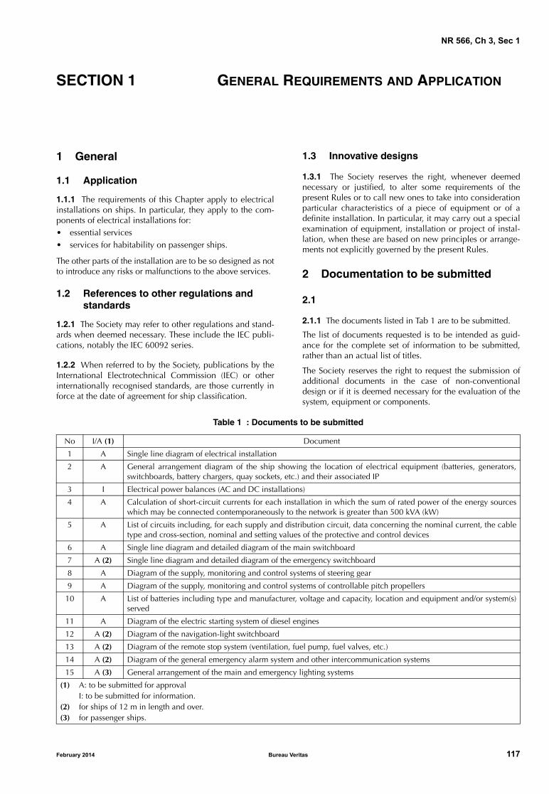
NR 566, Ch 3, Sec 1
SECTION 1 GENERAL REQUIREMENTS AND APPLICATION
1 General
1.1 Application
1.1.1 The requirements of this Chapter apply to electricalinstallations on ships. In particular, they apply to the com-ponents of electrical installations for: • essential services• services for habitability on passenger ships.
The other parts of the installation are to be so designed as notto introduce any risks or malfunctions to the above services.
1.2 References to other regulations and standards
1.2.1 The Society may refer to other regulations and stand-ards when deemed necessary. These include the IEC publi-cations, notably the IEC 60092 series.
1.2.2 When referred to by the Society, publications by theInternational Electrotechnical Commission (IEC) or otherinternationally recognised standards, are those currently inforce at the date of agreement for ship classification.
February 2014 Bureau Ve
1.3 Innovative designs
1.3.1 The Society reserves the right, whenever deemednecessary or justified, to alter some requirements of thepresent Rules or to call new ones to take into considerationparticular characteristics of a piece of equipment or of adefinite installation. In particular, it may carry out a specialexamination of equipment, installation or project of instal-lation, when these are based on new principles or arrange-ments not explicitly governed by the present Rules.
2 Documentation to be submitted
2.1
2.1.1 The documents listed in Tab 1 are to be submitted.
The list of documents requested is to be intended as guid-ance for the complete set of information to be submitted,rather than an actual list of titles.
The Society reserves the right to request the submission ofadditional documents in the case of non-conventionaldesign or if it is deemed necessary for the evaluation of thesystem, equipment or components.
Table 1 : Documents to be submitted
No I/A (1) Document
1 A Single line diagram of electrical installation
2 A General arrangement diagram of the ship showing the location of electrical equipment (batteries, generators,switchboards, battery chargers, quay sockets, etc.) and their associated IP
3 I Electrical power balances (AC and DC installations)
4 A Calculation of short-circuit currents for each installation in which the sum of rated power of the energy sourceswhich may be connected contemporaneously to the network is greater than 500 kVA (kW)
5 A List of circuits including, for each supply and distribution circuit, data concerning the nominal current, the cabletype and cross-section, nominal and setting values of the protective and control devices
6 A Single line diagram and detailed diagram of the main switchboard
7 A (2) Single line diagram and detailed diagram of the emergency switchboard
8 A Diagram of the supply, monitoring and control systems of steering gear
9 A Diagram of the supply, monitoring and control systems of controllable pitch propellers
10 A List of batteries including type and manufacturer, voltage and capacity, location and equipment and/or system(s)served
11 A Diagram of the electric starting system of diesel engines
12 A (2) Diagram of the navigation-light switchboard
13 A (2) Diagram of the remote stop system (ventilation, fuel pump, fuel valves, etc.)
14 A (2) Diagram of the general emergency alarm system and other intercommunication systems
15 A (3) General arrangement of the main and emergency lighting systems
(1) A: to be submitted for approvalI: to be submitted for information.
(2) for ships of 12 m in length and over.(3) for passenger ships.
ritas 117

NR 566, Ch 3, Sec 1
Plans are to include all the data necessary for their interpre-tation, verification and approval.
3 Definitions
3.1 General
3.1.1 Unless otherwise stated, the terms used in this Chap-ter have the definitions laid down by the IEC standards.
The definitions given in the following requirements alsoapply.
3.2 Essential services
3.2.1 Services essential for the navigation, steering ormanoeuvring of the ship, the safety of human life, andundertake activities connected with its operation, as far asclass is concerned.
3.2.2 For ships of less than 24 m in length, essential serv-ices may include but are not limited to following services:
• starting equipment of diesel engines
• steering gear
• bilge pumps
• bilge level detection
• lighting
• navigation lights
• radiocommunication equipment
• fuel supply pumps, lubricating oil pumps and coolingwater pumps for main and auxiliary engines, engineroom fans if required for normal operation.
3.2.3 For ships of 24 m in length and over, essential serv-ices may in addition to those listed in [3.2.2] include butare not limited to following additional services:
• electric generator and associated power sources theabove equipments
• windlasses
• fire detection and alarm system
• fire extinguishing systems
• ventilation fans for engine rooms
• emergency battery charger
• internal safety communication equipment.
3.3 Low-voltage systems
3.3.1 Alternating current systems with rated voltagesgreater than 50 V r.m.s. up to 1000 V r.m.s. inclusive anddirect current systems with a maximum instantaneous valueof the voltage under rated operating conditions greater than50 V up to 1500 V inclusive.
118 Bureau Ve
3.4 Safety voltage
3.4.1 Voltage which does not exceed 50 V a.c. r.m.sbetween conductors, or between any conductor and earth,in a circuit isolated from the supply by means such as asafety isolating transformer, or convertor with separatewindings.
Voltage which does not exceed 50 V d.c. between conduc-tors, or between any conductor and earth, in a circuit whichis isolated from higher voltage circuits.
Note 1: Consideration should be given to the reduction of the limitof 50 V under certain conditions, such as wet surroundings orexposure to heavy seas or where direct contact with live parts isinvolved.
Note 2: The voltage limit should not be exceeded either at full loador at no-load, but it is assumed, for the purpose of this definition,that any transformer or convertor is operated at its rated supplyvoltage.
3.5 DC systems of distribution
3.5.1 Two-wire d.c. system
A d.c. system comprising two conductors only, betweenwhich the load is connected.
3.6 AC systems of distribution
3.6.1 Single-phase two-wire a.c. system
A single-phase a.c. system comprising two conductorsonly, between which the load is connected.
3.6.2 Single-phase three-wire a.c. system
A single-phase a.c. system comprising two conductors anda neutral wire, the supply being taken from the two outerconductors or from the neutral wire and either outer con-ductor, the neutral wire carrying only the difference current.
3.6.3 Three-phase three-wire system
A system comprising three conductors connected to a three-phase supply.
3.6.4 Three-phase four-wire system
A system comprising four conductors of which three areconnected to a three-phase supply and the fourth to a neu-tral point in the source of supply.
3.6.5 Three-phase five-wire system
A system comprising five conductors of which three areconnected to a three-phase supply, the fourth to a neutralpoint in the source of supply and the fifth is the separateprotective conductor.
3.7 Hull return system
3.7.1 A system in which insulated conductors are providedfor connection to one pole or phase of the supply, the hullof the ship or other permanently earthed structure beingused for effecting connections to the other pole or phase.
ritas February 2014
NR 566, Ch 3, Sec 1
3.8 Earthed
3.8.1 Connected to the general mass of the hull of the shipin such a manner as will ensure at all times an immediatedischarge of electrical energy without danger.Note 1: A conductor is said to be “solidly earthed” when it is elec-trically connected to the hull without a fuselink, switch, circuitbreaker, resistor, or impedance, in the earth connection.
Note 2: In the USA, “grounded” is used instead of “earthed”.
3.9 Main source of electrical power
3.9.1 A source intended to supply electrical power to themain switchboard for distribution to all services necessaryfor maintaining the ship in normal operational and habita-ble condition.
3.10 Main switchboard
3.10.1 A switchboard which is directly supplied by themain source of electrical power and is intended to distributeelectrical energy to the ship’s services.
3.11 Emergency source of electrical power
3.11.1 A source of electrical power, intended to supply theemergency switchboard in the event of failure of the supplyfrom the main source of electrical power.
3.12 Emergency condition
3.12.1 A condition under which any services needed fornormal operational and habitable conditions are not inworking order due to failure of the main source of electricalpower.
3.13 Emergency switchboard
3.13.1 A switchboard which in the event of failure of themain electrical power supply system is directly supplied bythe emergency source of electrical power and is intended todistribute electrical energy to the emergency services. Theemergency switchboard may be supplied by the mainswitchboard under normal operation.
3.14 Normal operational and habitable condition
3.14.1 A condition under which the ship as a whole, themachinery, services, means and aids ensuring propulsion,ability to steer, safe navigation, fire and flooding safety,internal and external communications and signals, meansof escape, and emergency boat winches, as well as thedesigned comfortable conditions of habitability are in work-ing order and functioning normally.
3.15 Distribution board
3.15.1 A switchgear and controlgear assembly arranged forthe distribution of electrical energy to final circuits.
February 2014 Bureau Ve
3.16 Engine negative terminal
3.16.1 Terminal on the engine to which the negative cableof a battery system is connected.
3.17 Final circuit
3.17.1 Portion of a wiring system extending beyond thefinal overcurrent protection device for that circuit.
3.18 Overcurrent protection device
3.18.1 Device, such a fuse or circuit breaker, designed tointerrupt the circuit when the current exceeds a predeter-mined value for a predetermined time.
3.19 Circuit breaker
3.19.1 Mechanical switching device capable of making,carrying and breaking currents under normal circuit condi-tions, and also making, carrying for a specified time andbreaking currents under specified abnormal conditions suchas those of a short-circuit.
3.20 Generator
3.20.1 A device which creates d.c. or a.c. (alternator) powerfor distribution to the electrical system onboard a ship.
3.21 Generating set
3.21.1 A generating set is the combination of a generatorwith a driven engine which is not a main propulsion engine.
3.22 Fuse
3.22.1 Device that by fusing of one or more of its specifi-cally designed and proportioned components, opens thecircuit in which it is inserted by breaking the current whenthis exceeds a given value for a sufficient time. The fusecomprises all the parts that form the complete device.
3.23 Protective conductor
3.23.1 Conductor provided for purposes of safety, forexample, protection against electric shock by electricallyconnecting any of the exposed and extraneous conductiveparts of electrical equipment of a ship with non-metallichull to the ship’s main earth.Note 1: In the case of a ship with metallic hull, exposed and extra-neous conductive parts may be bonded to the ship’s hull by perma-nent and reliable metal to metal joints of negligible impedance.
3.24 Bond
3.24.1 Connection of non-current carrying parts to ensurecontinuity of electrical connection, or to equalize thepotential between parts comprising, for example, thearmour or lead sheath of adjacent length of cable, the bulk-head, etc. For example bulkhead and cables in a radio-receiving room.
ritas 119
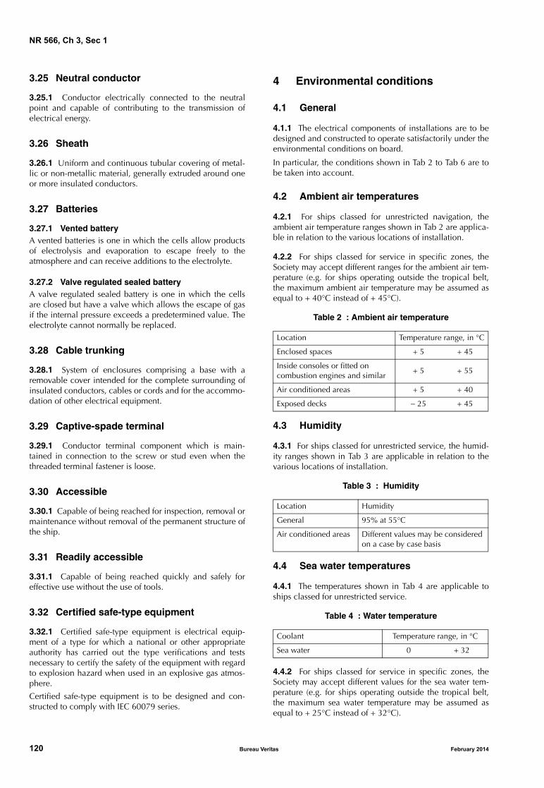
NR 566, Ch 3, Sec 1
3.25 Neutral conductor
3.25.1 Conductor electrically connected to the neutralpoint and capable of contributing to the transmission ofelectrical energy.
3.26 Sheath
3.26.1 Uniform and continuous tubular covering of metal-lic or non-metallic material, generally extruded around oneor more insulated conductors.
3.27 Batteries
3.27.1 Vented batteryA vented batteries is one in which the cells allow productsof electrolysis and evaporation to escape freely to theatmosphere and can receive additions to the electrolyte.
3.27.2 Valve regulated sealed batteryA valve regulated sealed battery is one in which the cellsare closed but have a valve which allows the escape of gasif the internal pressure exceeds a predetermined value. Theelectrolyte cannot normally be replaced.
3.28 Cable trunking
3.28.1 System of enclosures comprising a base with aremovable cover intended for the complete surrounding ofinsulated conductors, cables or cords and for the accommo-dation of other electrical equipment.
3.29 Captive-spade terminal
3.29.1 Conductor terminal component which is main-tained in connection to the screw or stud even when thethreaded terminal fastener is loose.
3.30 Accessible
3.30.1 Capable of being reached for inspection, removal ormaintenance without removal of the permanent structure ofthe ship.
3.31 Readily accessible
3.31.1 Capable of being reached quickly and safely foreffective use without the use of tools.
3.32 Certified safe-type equipment
3.32.1 Certified safe-type equipment is electrical equip-ment of a type for which a national or other appropriateauthority has carried out the type verifications and testsnecessary to certify the safety of the equipment with regardto explosion hazard when used in an explosive gas atmos-phere.
Certified safe-type equipment is to be designed and con-structed to comply with IEC 60079 series.
120 Bureau Ve
4 Environmental conditions
4.1 General
4.1.1 The electrical components of installations are to bedesigned and constructed to operate satisfactorily under theenvironmental conditions on board.
In particular, the conditions shown in Tab 2 to Tab 6 are tobe taken into account.
4.2 Ambient air temperatures
4.2.1 For ships classed for unrestricted navigation, theambient air temperature ranges shown in Tab 2 are applica-ble in relation to the various locations of installation.
4.2.2 For ships classed for service in specific zones, theSociety may accept different ranges for the ambient air tem-perature (e.g. for ships operating outside the tropical belt,the maximum ambient air temperature may be assumed asequal to + 40°C instead of + 45°C).
Table 2 : Ambient air temperature
4.3 Humidity
4.3.1 For ships classed for unrestricted service, the humid-ity ranges shown in Tab 3 are applicable in relation to thevarious locations of installation.
Table 3 : Humidity
4.4 Sea water temperatures
4.4.1 The temperatures shown in Tab 4 are applicable toships classed for unrestricted service.
Table 4 : Water temperature
4.4.2 For ships classed for service in specific zones, theSociety may accept different values for the sea water tem-perature (e.g. for ships operating outside the tropical belt,the maximum sea water temperature may be assumed asequal to + 25°C instead of + 32°C).
Location Temperature range, in °C
Enclosed spaces + 5 + 45
Inside consoles or fitted on combustion engines and similar
+ 5 + 55
Air conditioned areas + 5 + 40
Exposed decks − 25 + 45
Location Humidity
General 95% at 55°C
Air conditioned areas Different values may be considered on a case by case basis
Coolant Temperature range, in °C
Sea water 0 + 32
ritas February 2014

NR 566, Ch 3, Sec 1
Table 5 : Inclination of ship
Table 6 : Vibration levels
Type of machinery, equipment or component
Angles of inclination, in degrees (1)
Athwartship Fore-and-aft
staticdynamic
(4)static
dynamic (5)
Machinery and equipment relative to main electrical power installation 15 22,5 5 7,5
Machinery and equipment relative to the emergency power installation and crew andpassenger safety systems of the ship (e.g. emergency source of power, emergency firepumps, etc.)
22,5 (2) 22,5 (2) 10 10
Switchgear and associated electrical and electronic components and remote control sys-tems (3)
22,5 22,5 10 10
(1) Athwartship and fore-and-aft angles may occur simultaneously in their most unfavourable combination.(2) In the case of gas carriers or chemical tankers, the emergency power supply must also remain operable with the ship flooded to
a final athwartship inclination up to a maximum of 30°.(3) No undesired switching operations or functional changes may occur up to an angle of inclination of 45°.(4) The period of dynamic inclination may be assumed equal to 10 s.(5) The period of dynamic inclination may be assumed equal to 5 s.
LocationFrequency range,
in HzDisplacement amplitude,
in mmAcceleration amplitude
g
Machinery spaces, command and control stations,accommodation spaces, exposed decks, cargo spaces
from 2,0 to 13,2 1,0 −
from 13,2 to 100 − 0,7
On air compressors, on diesel engines and similarfrom 2,0 to 25,0 1,6 −
from 25,0 to 100 − 4,0
Mastsfrom 2,0 to 13,2 3,0 −
from 13,2 to 50 − 2,1
4.5 Salt mist
4.5.1 The applicable salt mist content in the air is to be1mg/m3.
4.6 Inclinations
4.6.1 The inclinations applicable are those shown in Tab 5.
The Society may consider deviations from these angles ofinclination taking into consideration the type, size and serv-ice conditions of the ships.
4.7 Vibrations
4.7.1 In relation to the location of the electrical compo-nents, the vibration levels given in Tab 6 are to be assumed.
4.7.2 The natural frequencies of the equipment, their sus-pensions and their supports are to be outside the frequencyranges specified.
Where this is not possible using a suitable constructionaltechnique, the equipment vibrations are to be dumped so asto avoid unacceptable amplifications.
February 2014 Bureau Ve
5 Quality of power supply
5.1 General
5.1.1 All electrical components supplied from the mainand emergency systems are to be so designed and manufac-tured that they are capable of operating satisfactorily underthe normally occurring variations in voltage and frequencyspecified from [5.2] to [5.4].
5.2 a.c. distribution systems
5.2.1 For alternating current components the voltage andfrequency variations of power supply shown in Tab 7 are tobe assumed.
Table 7 : Voltage and frequency variationsof power supply in a.c.
ParameterVariations
Continuous Transient
Voltage + 6% − 10% ± 20% (recovery time: 1,5 s)
Frequency ± 5% ± 10% (recovery time: 5 s)
Note 1: For alternating current components supplied by emer-gency generating sets, different variations may be considered.
ritas 121

NR 566, Ch 3, Sec 1
5.3 d.c. distribution systems
5.3.1 For direct current components the power supply vari-ations shown in Tab 8 are to be assumed.
Table 8 : Voltage variations in d.c.
5.3.2 For direct current components supplied by electricalbattery the following voltage variations are to be assumed:
• +30% to −25% for components connected to the bat-tery during charging
• +20% to −25% for components not connected to thebattery during charging.
Note 1: Different voltage variations as determined by the charg-
ing/discharging characteristics, including ripple voltage from the
charging device, may be considered.
5.3.3 Any special system, e.g. electronic circuits, whosefunction cannot operate satisfactorily within the limitsshown in the tables should not be supplied directly from thesystem but by alternative means, e.g. through stabilizedsupply.
5.4 Harmonic distortions
5.4.1 For components intended for systems without sub-stantially static converter loads and supplied by synchro-nous generators, it is assumed that the total voltageharmonic distortion does not exceed 5%, and the singleharmonic does not exceed 3% of the nominal voltage.
Figure 1 : Harmonic distortions
Parameters Variations
Voltage tolerance (continuous) ± 10%
Voltage cyclic variation 5%
Voltage ripple (a.c. r.m.s. over steady d.c. voltage)
10%
10
5
1
0,11 3 10 15 100
ν
U Uν
(%)
122 Bureau Ve
5.4.2 For components intended for systems fed by staticconverters, and/or systems in which the static converterload predominates, it is assumed that:
• the single harmonics do not exceed 5% of the nominalvoltage up to the 15th harmonic of the nominal fre-quency, decreasing to 1% at the 100th harmonic (seeFig 1), and that
• the total harmonic distortion does not exceed 10%.
5.4.3 Higher values for the harmonic content (e.g. in elec-tric propulsion plant systems) may be accepted on the basisof correct operation of all electrical devices.
6 Electromagnetic compatibility
6.1
6.1.1 Electrical and electronic equipment on the bridgeand in the vicinity of the bridge, not required neither byclassification rules nor by International Conventions are notto cause electromagnetic interference which may causeinterference on required equipment.
Note 1: See also IEC Publication 60533 - “Electromagnetic Com-patibility of Electrical and Electronic Installations in Ships and ofMobile and Fixed Offshore Units”.
7 Materials
7.1 General
7.1.1 In general, and unless it is adequately protected, allelectrical equipment is to be constructed of durable, flame-retardant, moisture-resistant materials which are not subjectto deterioration in the atmosphere and at the temperaturesto which they are likely to be exposed. Particular considera-tion is to be given to sea air and oil vapour contamination.
Note 1: The flame-retardant and moisture-resistant characteristicsmay be verified by means of the tests cited in IEC Publication60092-101 or in other recognised standards.
7.1.2 Where the use of incombustible materials or liningwith such materials is required, the incombustibility charac-teristics may be verified by means of the test cited in IECPublication 60092-101 or in other recognised standards.
7.2 Insulating materials for windings
7.2.1 Insulated windings are to be resistant to moisture, seaair and oil vapour unless special precautions are taken toprotect insulants against such agents.
7.2.2 The insulation classes given in Tab 9 may be used inaccordance with IEC Publication 60085.
ritas February 2014

NR 566, Ch 3, Sec 1
Table 9 : Insulation classes
ClassMaximum continuous operating
temperature, in °C
A 105
E 120
B 130
F 155
H 180
February 2014 Bureau Ve
7.3 Insulating materials for cables
7.3.1 The materials used for insulation are to comply withIEC Publication 60092-351 and to have the thicknessesspecified for each type of cable in the relevant standard.The maximum permissible rated temperature is specified forthe various materials.
7.3.2 Material and thicknesses other than those in [7.3.1]will be specially considered by the Society.
ritas 123

NR 566, Ch 3, Sec 2
SECTION 2 SYSTEM DESIGN
1 Supply systems and characteristics of the supply
1.1 Supply systems
1.1.1 The following distribution systems may be used:
a) on d.c. installations:
• two-wire insulated
• two-wire with negative earthed
b) on a.c. installations:
• single-phase two-wire insulated
• single-phase two-wire with neutral earthed
• three-phase three-wire with neutral insulated ordirectly earthed
• three-phase four-wire with neutral earthed (TN-CType)
• three-phase five-wire with neutral earthed (TN-SType).
124 Bureau Ve
1.1.2 The hull return system of distribution is not to be usedfor voltage greater than 50 Volts.
1.1.3 The requirement of [1.1.2] does not preclude underconditions approved by the Society the use of:
a) limited and locally earthed system, or
b) insulation level monitoring devices provided the circu-lation current does not exceed 30 mA under the mostunfavourable conditions.
1.2 Maximum voltage
1.2.1 The maximum voltage for both alternating currentand direct current low-voltage systems of supply for theship’s services are given in Tab 1.
1.2.2 Voltages exceeding those shown will be speciallyconsidered in the case of specific systems.
1.2.3 For high voltage systems, see the Rules for SteelShips, Ch 2, Sec 13.
Table 1 : Maximum voltages for various ship services
Use Maximum voltage V
For permanently installed andconnected to fixed wiring
Power equipment 1000
Heating equipment (except in accommodation spaces) 500
Cooking equipment 500
Lighting 250
Space heaters in accommodation spaces 250
Control (1), communication (including signal lamps) and instrumentationequipment
250
For permanently installed andconnected by flexible cable
Power and heating equipment, where such connection is necessary becauseof the application (e.g. for moveable cranes or other hoisting gear)
1000
For socket-outlets supplying Portable appliances which are not hand-held during operation(e.g. refrigerated containers) by flexible cables
1000
Portable appliances and other consumers by flexible cables 250
Equipment requiring extra precaution against electric shock where a isolating transformer is used to supply one appliance (2)
250
Equipment requiring extra precaution against electric shock with or withouta safety transformer (2)
50
(1) For control equipment which is part of a power and heating installation (e.g. pressure or temperature switches for start/stopmotors), the same maximum voltage as allowed for the power and heating equipment may be used provided that all compo-nents are constructed for such voltage. However, the control voltage to external equipment is not to exceed 500 V.
(2) Both conductors in such systems are to be insulated from earth.
ritas February 2014

NR 566, Ch 3, Sec 2
2 Sources of electrical power
2.1 Ships of less than 12 m in length
2.1.1 For ships whose length is less than 12 m, require-ments mentioned in [2.2], [2.3] and [2.4] may be omitted.
2.1.2 These ships are to be fitted with a source of electricalpower of sufficient capacity to supply all essential servicesnecessary for their normal operation. The source of powermay consist of batteries and two d.c. or a.c. generators.
2.1.3 Where d.c. generators are provided, they are to becapable of supplying the total load and simultaneously becapable of charging the batteries to 80% charge within10 hours.
2.1.4 Where a.c. power is provided, it may be done by oneor a combination of the following means:
a) one or more shore-power connections
b) inverter supplying a.c. power from the ship’s d.c. system
c) on-board a.c. generator(s) supplying the required systemload.
2.1.5 Generator may be driven by its own prime mover, orbe powered from propulsion machinery, or be a shaft gener-ator.
2.1.6 For ships with sheltered area notation or with coastalarea notation, the main source of electrical power may con-sist of a single generator. In this case an alternative means ofstarting the generator is to be provided. In addition, in casethis generator is unavailable, the electric services necessaryto the propulsion and safety of the ship are to be suppliedwith a battery.
2.2 Main source of electrical power
2.2.1 A main source of electrical power and associatedswitchboard is to be provided, of sufficient capacity to sup-ply all electrical essential services necessary for maintainingthe ship in normal operational conditions and, in additionfor passenger ships, for maintaining normal habitable con-ditions, without recourse to the emergency source of elec-trical power.
2.2.2 The main source of power may be a.c. or d.c. system.
2.2.3 Where electrical energy is required for services nec-essary to the propulsion, navigation and safety of the ship,and in addition for passenger ships for maintaining normalhabitable conditions, the main source of electrical power isto consist of at least two generating sets. The capacity ofthese generating sets is to be such that in the event of anyone generating set being stopped it will still be possible tosupply all services necessary to provide normal operationalconditions of propulsion and safety.
February 2014 Bureau Ve
Such capacity is, in addition, to be sufficient to start thelargest motor without causing any other motor to stop orhaving any adverse effect on other equipment in operation.
2.2.4 Generators (a.c. or d.c.) driven by the propulsionmachinery may be accepted as forming the main source ofelectrical power, if in all manoeuvring conditions includingthe propeller being stopped, the capacity of these genera-tors is sufficient to provide the electrical power to complywith [2.2.1]. They are to be not less effective and reliablethan the independent generating sets. One propulsionengine being unavailable is no to result in more than onegenerator being unavailable as well.
2.2.5 For the purpose of calculating the necessary capacity,it is essential to consider which consumers can be expectedto be in use simultaneously, in the various operational con-ditions of the ship.
2.2.6 In case of a ship with sheltered area notation otherthan a passenger ship, the main electric power source mayonly consist of one generator driven or not from the propul-sion engine. In case this generator is unavailable, the elec-tric services necessary to the propulsion and safety of theship are to be supplied with a battery that may be the emer-gency source.
2.3 Additional requirements for passenger ships and for other ships of 24 m in length and over
2.3.1 Where transformers, converters or similar appliancesconstitute an essential part of the electrical system to ensurethe supply to the propulsion, the steering of the ship, andfor passenger ships the normal habitable conditions, thesystem is to be so arranged as to ensure the same continuityof supply as stated in this sub-article.
2.3.2 This may be achieved by arranging at least two three-phase or three single-phase transformers supplied, pro-tected and installed as indicated in Fig 1, so that with anyone transformer not in operation, the remaining trans-former(s) is (are) sufficient to ensure the supply to the abovementioned services stated in [2.3.1].
Each transformer required is to be located as a separate unitwith separate enclosure or equivalent, and is to be servedby separate circuits on the primary and secondary sides.Each of the primary and secondary circuits is to be providedwith switchgears and protection devices in each phase.
Where special precaution are taken to rapidly replace thefaulty transformer, i.e. less than 30 minutes, only one sparethree-phase transformer or one spare single-phase elementare required
Suitable interlocks or a warning label are to be provided inorder to prevent ance or repair of one single-phase trans-former unless both switchgears are opened on their primaryand secondary sides.
ritas 125

NR 566, Ch 3, Sec 2
Figure 1 : Transformers - Continuity of supply
'P' 'P'RST
RST
Three-phase transformers
enclosure or separation
RST
RST
Single-phase transformers
2.4 Emergency source of electrical power
2.4.1 A self-contained emergency source of electricalpower independent of the main source of power is to beprovided.
For multihull ships, where the main source of electricalpower is located in two different hulls, each of which hav-ing its own self-contained power system, including powerdistribution and control systems, completely independent ofeach other and so arrange that a fire or other casualty in anyone hull will not affect the power distribution from theother, or to the services required in [3.5.3] to [3.5.5], therequirements of this Sub-article may be considered as satis-fied without an additional emergency source of electricalpower, provided there is at least in each hull one generatorof sufficient capacity to satisfy the requirement of [3.5.3] to[3.5.5].
2.4.2 The emergency source of power may be:
a) a generator set driven by an auxiliary engine with a fueloil supply and a cooling system independent from themain engine
b) or a storage battery.
2.4.3 The emergency source of power, associated distribu-tion switchboard, and if any, transitional source of emer-gency power are to be located outside the engine room,above the uppermost continuous deck and are to be readilyaccessible from the open deck. They are not to be locatedforward of the collision bulkhead.
2.4.4 In all cases the location of the emergency source ofelectrical power is to be such as to ensure that fire or othercasualty in the space containing the main source of electri-cal power will not interfere with its continuous operation.
126 Bureau Ve
2.4.5 Where the emergency source of electrical power isan accumulator battery, it is to be capable of:
a) carrying the emergency electrical load without recharg-ing while maintaining the voltage of the battery through-out the discharge period within 12% above or below itsnominal voltage
b) automatically connecting to the emergency switchboardin the event of failure of the main source of electricalpower; and
c) immediately supplying at least those services specifiedin [3.5.3].
2.4.6 An indicator is to be mounted in a continuouslymanned control position, to indicate when the battery con-stituting the emergency source of electrical power is beingdischarged.
2.4.7 Where the emergency source of electrical power is agenerator, it is to be:
a) driven by a suitable prime mover with an independentsupply of fuel, having a flash point (closed cup test) ofnot less than 43°C
b) when the ship is not a passenger ship, started automati-cally upon failure of the main source of electrical powersupply to the emergency switchboard unless a transi-tional source of emergency electrical power in accor-dance with [2.4.8] is provided. Where the emergencygenerator is automatically started, it is to be automati-cally connected to the emergency switchboard
c) when the ship is a passenger ship, started automaticallyupon failure of the main source of electrical power sup-ply to the emergency switchboard and shall be con-nected automatically to the emergency switchboard; inaddition, a transitional source of emergency electricalpower according to [2.4.8] is to be provided
ritas February 2014

NR 566, Ch 3, Sec 2
d) provided with a dedicated fuel oil supply tank fittedwith a low level alarm, arranged at level ensuring suffi-cient fuel oil capacity for the emergency services for theperiod of time as required in [3.5].
2.4.8 The transitional source of emergency electrical powerwhere required in [2.4.7], items b) and c), is to consist of anaccumulator battery so arranged to supply automatically inthe event of failure of either the main or the emergencysource of electrical power for half an hour at least the emer-gency lighting listed in [3.5.3], items a), b), c) and d).
2.4.9 Provision is to be made for the periodic testing of thecomplete emergency system and is to include the testing ofautomatic starting arrangements, where provided.
2.4.10 For the starting arrangement of the emergency gen-erating set, refer to [3.15.4].
3 Distribution
3.1 Earthed neutral systems
3.1.1 In earthed neutral systems, the source of power isconnected directly to earth, and all exposed conductiveparts of the installation are connected to the earthed pointof the ship’s power system by protective conductor(s) or viathe hull for steel ships.
3.1.2 The neutral conductor is to be earthed only at thesource of power, for example, at the onboard generator orsecondary of transformer.
3.1.3 The ship’s a.c. neutral is to be arranged to be earthedonly at the shore-power source when the ship’s a.c. systemis supplied from shore (i.e. the ship’s a.c. neutral is to bedisconnected from the ship’s earth when the shore power isconnected), unless the ship is fitted with an isolating trans-former.
3.1.4 System is to be effected by means independent of anyearthing arrangements of the non-current-carrying parts.
3.1.5 Earthed neutral systems are to be so designed that thepotential earth fault current:
a) does not exceed the design capacity of any part of thesystem
b) is of sufficient magnitude to operate any protection.
Note 1: Where the neutral point is connected directly to earth, theearth loop impedance is to be low enough to permit the passage ofcurrent at least three times the fuse rating for fuse protected circuitsor 1,5 times the tripping current of any circuit breaker used to pro-tect the circuit.
February 2014 Bureau Ve
3.2 Insulated systems
3.2.1 In insulated systems, the source of power is insulatedfrom earth or connected to the earth through a sufficientlyhigh impedance.
3.2.2 Every insulated distribution system, whether primaryor secondary, for power, heating or lighting, is to be pro-vided with suitable means to monitor the insulation level toearth (i.e. the values of electrical insulation to earth).
Note 1: A primary system is one supplied directly by generators.Secondary systems are those supplied by transformers or convertors.
3.2.3 For ships of 24 m in length and over and for passen-ger ships, the device required in [3.2.2] is to be capable ofcontinuously monitoring the insulation level to earth and ofgiving an audible and visual indication of abnormally lowinsulation values.
3.3 A.C. distribution system
3.3.1 Where a.c. system is supplied by a combination ofseparate power sources (shore-power connection, on-boarda.c. generator(s) or inverter), individual circuits are not to becapable of being energized by more than one source ofelectrical power at a time. The transfer from one power-source circuit to another is to be made by a means whichopens all current-carrying conductors before closing theother source circuit, prevents arc-over between contactsand is interlocked by mechanical or electromechanicalmeans. All current-carrying conductors are to be brokensimultaneously when changing power source.
Note 1: Two or more three-phase generators, when properly syn-chronised are to be treated as one source.
3.3.2 The current consuming units are to be so grouped inthe final circuits that the load on each phase will, undernormal conditions, be balanced as far as possible at theindividual distribution and section boards as well as themain switchboard.
3.3.3 The continuity of supply is not to be impaired byload-produced harmonic distorsion or high load charges.
3.4 D.C. distribution system supplied from batteries
3.4.1 Each battery or group of batteries is to be capable ofbeing isolated from the d.c. system which is supplied, nor-mally by a switch. Isolation switches are to be placed in areadily accessible location as closed as practical to the bat-tery or group of batteries, but outside the battery compart-ment or container.
3.4.2 Remote controlled isolation switches are admittedproviding they also permit safe manual control.
ritas 127

NR 566, Ch 3, Sec 2
3.4.3 The following systems may be connected betweenthe isolation switch and the battery:
a) electronic devices with protected memory and protec-tive devices such as bilge pumps and alarms, if individu-ally protected by a circuit breaker or fuse as close aspractical to the battery terminal
b) ventilation exhaust blower of engine/fuel-tank compart-ment if separately protected by a fuse or circuit breakeras close as practical to the battery terminal
c) charging devices which are intended to be used whenthe ship is unattended (for example, solar panels, windgenerator) if individually protected by a fuse or circuitbeaker as close as practical to the battery terminal.
3.4.4 The minimum continuous rating of the battery selec-tion/isolation switch is to be at least equal to the maximumcurrent for which the main circuit breaker is rated and alsothe intermittent load of the starter motor circuit, or the cur-rent rating of the feeder conductor, whichever is less.
3.4.5 For systems where both positive and negative con-ductors are isolated from earth, double pole switches are tobe used.
3.5 Emergency distribution of electrical power
3.5.1 Requirements of this sub-article may be omitted forships of less than 12 m in length.
3.5.2 The emergency switchboard is to be supplied duringnormal operation from the main switchboard by an inter-connector feeder which is to be adequately protected at themain switchboard against overload and short-circuit andwhich is to be automatically disconnected at the emergencyswitchboard upon failure of the main source of electricalpower.
3.5.3 The emergency source of electrical power is to becapable of supplying simultaneously at least the followingservices for a period of 6 hours:
a) the emergency lighting to assist escape from allenclosed spaces and to illuminate the disembarkationpositions and over the sides
b) the emergency lighting in the machinery spaces andnavigation bridge
c) the emergency lighting in the room which is located theengine room fixed-fire extinguishing system if any
d) the navigation lights and other lights required by theInternational Regulations for Preventing Collisions atSea (COLREG) in force and/or by the Flag Authority
e) the ship’s whistle if electrically powered
f) the radiocommunication equipment
g) the fire detection and fire alarm system if fitted on board
128 Bureau Ve
h) the control and alarm system of the fixed fire fightingsystem
i) general alarm system required in [3.11].
Note 1: Attention is drawn to compliance with possible nationalregulations.
3.5.4 For ships of 24 m in length and over, the emergencysource of electrical power is to be capable of supplyingsimultaneously for a period of 6 hours the services requiredin [3.5.3] and:
a) the means of communication between the navigationbridge and the steering gear compartment
b) the means of communication between the navigatingbridge and the position in the machinery space or con-trol room from which the engines are normally control-led
c) the emergency fire pump for ships greater than 24 m inlength, if electrically driven.
3.5.5 For passenger ships the emergency source of electri-cal power is to be capable of supplying simultaneously for aperiod of 12 hours the services required in [3.5.4] and thefollowing ones:
a) the public address system or other effective means ofcommunication required in [3.11.2]
b) the low-location lighting required for the ships havingthe navigation notation coastal area and with more than50 passengers, where electric type, and
c) sprinkler pump or equivalent system, for passengerships if required in Ch 4, Sec 1, [2.2.2].
3.5.6 For passenger ships having the navigation notationsheltered area, the Society may, if satisfied that an adequatestandard of safety would be attained, accept a lesser periodof time that the periods specified in [3.5.5] but not less than6 hours.
3.5.7 The services to be supplied by the emergency sourceof power supply and the autonomy requested are recapitu-lated in Tab 2.
3.6 Specific requirements for ro-ro passenger ships
3.6.1 Ro-ro passenger ship electrical installations are tocomply with the Rules for Steel Ships, Pt D, Ch 12, Sec 4,[2] to Pt D, Ch 12, Sec 4, [4].
3.7 Shore connection
3.7.1 Where arrangements are made for supplying theelectrical installation from a source on shore or elsewhere,a suitable connection box is to be installed on the ship in aconvenient location to receive the flexible cable from theexternal source.
3.7.2 Permanently fixed cables of adequate rating are to beprovided for connecting the box to the main switchboard.
ritas February 2014
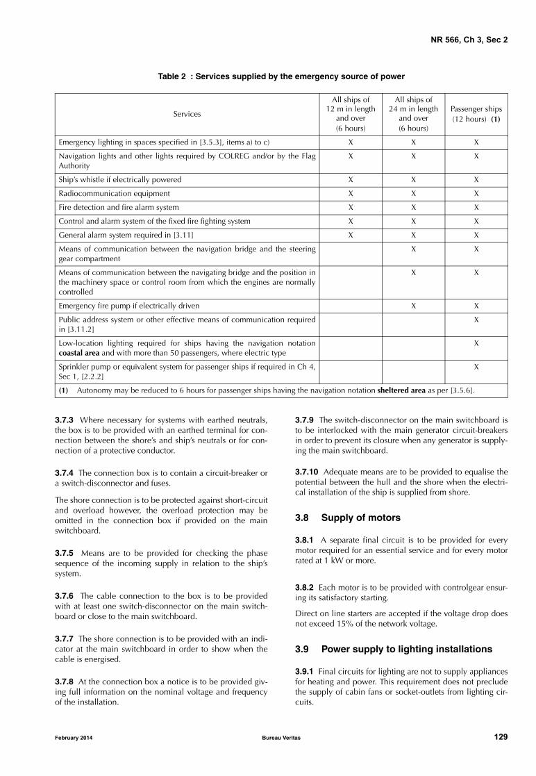
NR 566, Ch 3, Sec 2
Table 2 : Services supplied by the emergency source of power
Services
All ships of 12 m in length
and over(6 hours)
All ships of 24 m in length
and over(6 hours)
Passenger ships(12 hours) (1)
Emergency lighting in spaces specified in [3.5.3], items a) to c) X X X
Navigation lights and other lights required by COLREG and/or by the FlagAuthority
X X X
Ship’s whistle if electrically powered X X X
Radiocommunication equipment X X X
Fire detection and fire alarm system X X X
Control and alarm system of the fixed fire fighting system X X X
General alarm system required in [3.11] X X X
Means of communication between the navigation bridge and the steeringgear compartment
X X
Means of communication between the navigating bridge and the position inthe machinery space or control room from which the engines are normallycontrolled
X X
Emergency fire pump if electrically driven X X
Public address system or other effective means of communication requiredin [3.11.2]
X
Low-location lighting required for ships having the navigation notationcoastal area and with more than 50 passengers, where electric type
X
Sprinkler pump or equivalent system for passenger ships if required in Ch 4,Sec 1, [2.2.2]
X
(1) Autonomy may be reduced to 6 hours for passenger ships having the navigation notation sheltered area as per [3.5.6].
3.7.3 Where necessary for systems with earthed neutrals,the box is to be provided with an earthed terminal for con-nection between the shore’s and ship’s neutrals or for con-nection of a protective conductor.
3.7.4 The connection box is to contain a circuit-breaker ora switch-disconnector and fuses.
The shore connection is to be protected against short-circuitand overload however, the overload protection may beomitted in the connection box if provided on the mainswitchboard.
3.7.5 Means are to be provided for checking the phasesequence of the incoming supply in relation to the ship’ssystem.
3.7.6 The cable connection to the box is to be providedwith at least one switch-disconnector on the main switch-board or close to the main switchboard.
3.7.7 The shore connection is to be provided with an indi-cator at the main switchboard in order to show when thecable is energised.
3.7.8 At the connection box a notice is to be provided giv-ing full information on the nominal voltage and frequencyof the installation.
February 2014 Bureau Ve
3.7.9 The switch-disconnector on the main switchboard isto be interlocked with the main generator circuit-breakersin order to prevent its closure when any generator is supply-ing the main switchboard.
3.7.10 Adequate means are to be provided to equalise thepotential between the hull and the shore when the electri-cal installation of the ship is supplied from shore.
3.8 Supply of motors
3.8.1 A separate final circuit is to be provided for everymotor required for an essential service and for every motorrated at 1 kW or more.
3.8.2 Each motor is to be provided with controlgear ensur-ing its satisfactory starting.
Direct on line starters are accepted if the voltage drop doesnot exceed 15% of the network voltage.
3.9 Power supply to lighting installations
3.9.1 Final circuits for lighting are not to supply appliancesfor heating and power. This requirement does not precludethe supply of cabin fans or socket-outlets from lighting cir-cuits.
ritas 129
NR 566, Ch 3, Sec 2
3.9.2 Final circuits for lighting supplying more than onelighting point and for socket-outlets are to be fitted withprotective devices having a current rating not exceeding16 A.
3.9.3 The emergency source of lighting is to be independ-ent of the general lighting system.
3.9.4 Lighting fittings in the main engine rooms and pas-senger spaces of ships of 12 metres and over are to be fedby at least two different final circuits in such a way that afailure of any one circuit does not reduce the lighting to aninsufficient level. One of these circuits may be suppliedfrom the emergency source of power.
3.10 Navigation and signalling lights
3.10.1 Every ship should be fitted with navigation lights incompliance with the requirements of the International Reg-ulations for Preventing Collisions At Sea, 1972, asamended.
The construction and installation of navigation lights is tobe to the satisfaction of the Appropriate Authority.
3.10.2 Navigation lights are to be connected separately toa dedicated distribution board placed in an accessible posi-tion on the ship and supplied from the main source ofpower.
3.10.3 Each navigation light is to be controlled and pro-tected in each insulated pole by a double-pole switch and afuse or, alternatively, by a double-pole circuit-breaker, fittedon the distribution board referred to in [3.10.2].
3.10.4 For ships of 12 m in length and over, the followingadditional requirements are to be complied with:
a) Provision is to be made at position mentioned in[3.10.2] to connect the navigation lights distributionboard to the emergency source of power by means of aseparate feeder and a manual or automatic changeoverswitch
b) When it is not possible to visually observe the operationof the navigation lights from the bridge deck, such lightsare to be provided with an automatic indicator givingaudible and/or visual warning in the event of failure of anavigation light.
If a visual signal connected in series with the navigationlight is used, means is to be provided to prevent theextinction of the navigation light due to the failure of thevisual signal.
3.11 General alarm
3.11.1 General alarm on all ships
Ships of 12 m in length and over are to be equipped with asystem enabling the general broadcast of an alarm. Thisalarm may consist of the ship's whistle or siren, provided itcan be heard in all parts of the ship when sailing.
130 Bureau Ve
3.11.2 General alarm specific requirements for passenger ships
a) For passenger ships of 12 m in length and over, the sys-tem required in [3.11.1] is to be supplemented by anelectrically operated bell or klaxon system, poweredfrom the ship’s main source of electrical power and alsothe emergency source of electrical power
b) for passenger ships of 50 passengers and over, in addi-tion to the system required in [3.11.1] a public addresssystem or other effective means of communication ena-bling simultaneous broadcast of messages from the nav-igation bridge to all spaces where persons onboard arenormally present (accommodation, open decks, publicand machinery spaces) is to be provided. This system isto be powered from the ship’s main source of electricalpower and the emergency source of electrical power.
Where an individual loudspeaker has a device for localsilencing, an override arrangement from the control sta-tion, is to be provided
c) for passenger ships of 200 passengers and over, the sys-tem required above is to be arranged to minimise theeffect of a single failure so that the alarm signal is stillaudible (above ambient noise levels) also in the case offailure of any one circuit or component, by means of theuse of:
• multiple amplifiers
• segregated cable routes to public rooms, alleyways,stairways and control stations
• more than one device for generating electronicsound signal
• electrical protection for individual loudspeakersagainst short-circuits.
3.12 Internal communications
3.12.1 Communications between the navigating bridge and the engine room
a) At least two independent means are to be provided forcommunicating orders from the navigating bridge to theposition in the machinery space or in the control roomfrom which the speed and the direction of the thrust ofthe propellers are normally controlled
b) The two means for communicating orders are to be fedby independent power supply
c) One of the two means for communicating ordersrequired in item a) may be portable for the ships of lessthan 24 m in length
d) For ships of less than 12 m in length, only one meansmay be acceptable.
3.12.2 Communications between the navigating bridge and the steering gear room
One means of communication is to be provided betweenthe navigating bridge and the steering gear room. Thismeans of communication may be portable for ships of lessthan 24 m in length.
ritas February 2014

NR 566, Ch 3, Sec 2
3.13 Bilge level alarms
3.13.1 Alarm is to be given to the navigating bridge in caseof flooding into the machinery space situated below theload line.
3.13.2 For crew boats, in addition to [3.13.1], an alarm isto be triggered at the bridge or in a continuously mannedposition in the case of high water level in all spaces locatedbelow the load line.
3.14 Specific requirements for special power services
3.14.1 The motors driving fans, oil fuel transfer pumps, andother pumps of the fuel oil system as well as the oil fuel sep-arators are to be provided with remote control in accord-ance with Ch 4, Sec 4, [5.1].
3.14.2 The means provided for stopping the power ventila-tion of the machinery spaces are to be entirely separatefrom the means provided for stopping ventilation of otherplaces.
3.14.3 For the supply and characteristics of the distributionof the following services see requirements listed:
a) Fire extinguishing systems: Ch 4, Sec 5, as applicable
b) Fire detection systems: Ch 4, Sec 3, [5.1.2]
c) Steering gear: Ch 2, Sec 3, [2.3].
3.15 Diesel engine starting system
3.15.1 Main engine starting systema) Where main internal combustion engine is arranged for
electrical starting, at least two separate batteries are tobe fitted.It is to be possible to select which battery or group ofbattery is used for the starting.Each battery or group of batteries is to be of a sufficientcapacity for ensuring at least the six consecutive startattempts of the main propulsion engine.
b) For multi-engine propulsion plants with electric startingdevice, each main engine may be equipped with onlyone starting battery, provided that each battery is capa-ble of being connected via a changeover switch andfixed cables to the starting system of the other mainengine. The arrangement is to be such that the connec-tion of the batteries in parallel can be avoided.The capacity of the batteries is to be sufficient to ensureat least 3 consecutive starts per engine. However, thetotal capacity is not to be less than 12 starts and neednot exceed 18 starts.
c) One of the batteries or group of batteries requested initem a) and item b) may also be used for supplying theship’s electrical services of:• all ships less than 12 m in length, or• all ships less than 24 m in length other than passen-
ger ships, or• all ships with navigation notation sheltered area.Capacity of starting batteries used for supplying otherservices is to be designed accordingly.
February 2014 Bureau Ve
d) It is to be possible to select which battery or group ofbatteries is used for which service and also to connectboth battery groups in parallel in an emergency to assistengine start.
Note 1: Service selection function may be combined with the isola-tion function required in [3.5.2].
3.15.2 Auxiliary engines starting systemElectrical starting arrangements of generating sets used forthe propulsion, steering or safety of the ship or used for abil-ity for the passenger ships are to have two separate storagebatteries or may be supplied by two separate circuits frommain engine storage batteries when these are provided. Inthe case of a single auxiliary engine, one battery is accepta-ble. The combined capacity of the batteries is to be suffi-cient for at least three starts for each engine.
3.15.3 Common requirements for main and auxiliary engines starting systems
a) Provision is to be made to maintain the stored energy ofstarting batteries at all times
b) Unless specified in [3.15.1], item c), the starting batter-ies are only to be used for starting and for the engine’salarm and monitoring.
3.15.4 Requirements for emergency generating setsFor starting arrangements of emergency generating sets, fol-lowing requirements apply:
a) Emergency generating sets are to be capable of beingreadily started in their cold condition at a temperatureof 0°C. If this is impracticable, or if lower temperaturesare likely to be encountered, provision acceptable tothe Society is to be made for the maintenance of heatingarrangements, to ensure ready starting of the generatingsets
b) Each emergency generating set arranged to be automati-cally started is to be equipped with starting devicesapproved by the Society with a stored energy capabilityof at least three consecutive starts.The source of stored energy is to be protected to pre-clude critical depletion by the automatic starting sys-tem, unless a second independent means of starting isprovided. In addition, a second source of energy is to beprovided for an additional three starts within 30 min-utes, unless manual starting can be demonstrated to beeffective
c) Provision is to be made to maintain the stored energy atall times
d) All of these starting, charging and energy storing devicesare to be located in the emergency generator space;these devices are not to be used for any purpose otherthan the operation of the emergency generating set.
3.16 Specific requirements for ships with electric propulsion
3.16.1 For ships propelled by at least one electric propul-sion motor and its electrical supply, all electrical compo-nents of the propulsion plant will be specially consideredby the Society according to requirements specified in theRules for Steel Ships, Pt C, Ch 2, Sec 14.
ritas 131
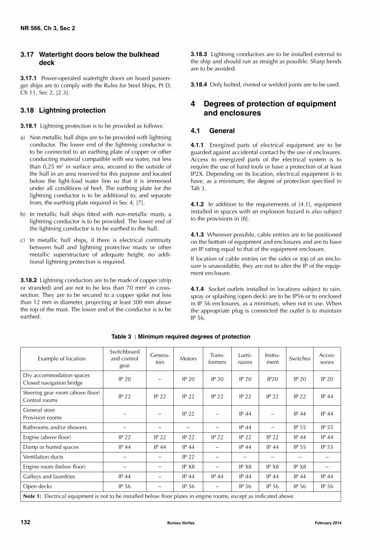
NR 566, Ch 3, Sec 2
3.17 Watertight doors below the bulkhead deck
3.17.1 Power-operated watertight doors on board passen-ger ships are to comply with the Rules for Steel Ships, Pt D,Ch 11, Sec 2, [2.3].
3.18 Lightning protection
3.18.1 Lightning protection is to be provided as follows:
a) Non metallic hull ships are to be provided with lightningconductor. The lower end of the lightning conductor isto be connected to an earthing plate of copper or otherconducting material compatible with sea water, not lessthan 0,25 m2 in surface area, secured to the outside ofthe hull in an area reserved for this purpose and locatedbelow the light-load water line so that it is immersedunder all conditions of heel. The earthing plate for thelightning conductor is to be additional to, and separatefrom, the earthing plate required in Sec 4, [7].
b) In metallic hull ships fitted with non-metallic masts, alightning conductor is to be provided. The lower end ofthe lightning conductor is to be earthed to the hull.
c) In metallic hull ships, if there is electrical continuitybetween hull and lightning protective masts or othermetallic superstructure of adequate height, no addi-tional lightning protection is required.
3.18.2 Lightning conductors are to be made of copper (stripor stranded) and are not to be less than 70 mm2 in cross-section. They are to be secured to a copper spike not lessthan 12 mm in diameter, projecting at least 300 mm abovethe top of the mast. The lower end of the conductor is to beearthed.
132 Bureau Ve
3.18.3 Lightning conductors are to be installed external tothe ship and should run as straight as possible. Sharp bendsare to be avoided.
3.18.4 Only bolted, riveted or welded joints are to be used.
4 Degrees of protection of equipment and enclosures
4.1 General
4.1.1 Energized parts of electrical equipment are to beguarded against accidental contact by the use of enclosures.Access to energized parts of the electrical system is torequire the use of hand tools or have a protection of at leastIP2X. Depending on its location, electrical equipment is tohave, as a minimum, the degree of protection specified inTab 3.
4.1.2 In addition to the requirements of [4.1], equipmentinstalled in spaces with an explosion hazard is also subjectto the provisions in [8].
4.1.3 Wherever possible, cable entries are to be positionedon the bottom of equipment and enclosures and are to havean IP rating equal to that of the equipment enclosure.
If location of cable entries on the sides or top of an enclo-sure is unavoidable, they are not to alter the IP of the equip-ment enclosure.
4.1.4 Socket outlets installed in locations subject to rain,spray or splashing (open deck) are to be IP56 or to enclosedin IP 56 enclosures, as a minimum, when not in use. Whenthe appropriate plug is connected the outlet is to maintainIP 56.
Table 3 : Minimum required degrees of protection
Example of locationSwitchboard and control
gear
Genera-tors
MotorsTrans-
formersLumi-naires
Instru-ment
SwitchesAcces-sories
Dry accommodation spacesClosed navigation bridge
IP 20 − IP 20 IP 20 IP 20 IP20 IP 20 IP 20
Steering gear room (above floor)Control rooms
IP 22 IP 22 IP 22 IP 22 IP 22 IP 22 IP 22 IP 44
General storeProvision rooms
− − IP 22 − IP 44 − IP 44 IP 44
Bathrooms and/or showers − − − − IP 44 − IP 55 IP 55
Engine (above floor) IP 22 IP 22 IP 22 IP 22 IP 22 IP 22 IP 44 IP 44
Damp or humid spaces IP 44 IP 44 IP 44 − IP 44 IP 44 IP 55 IP 55
Ventilation ducts − − IP 22 − − − − −
Engine room (below floor) − − IP X8 − IP X8 IP X8 IP X8 −
Galleys and laundries IP 44 − IP 44 IP 44 IP 44 IP 44 IP 44 IP 44
Open decks IP 56 − IP 56 − IP 56 IP 56 IP 56 IP 56
Note 1: Electrical equipment is not to be installed below floor plates in engine rooms, except as indicated above.
ritas February 2014
NR 566, Ch 3, Sec 2
4.1.5 Socket outlets installed in areas subject to flooding ormomentary submersion are to be in IP67 enclosure, as aminimum, also maintaining IP67 when an appropriate plugis inserted.
5 Diversity factors
5.1 General
5.1.1 The cables and protective devices of final circuits areto be rated in accordance with their connected load.
5.1.2 Circuits supplying two or more final circuits are to berated in accordance with the total connected load subject,where justifiable, to the application of a diversity (demand)factor in accordance with [5.1.3] and [5.1.4].
Where spare-circuits are provided on a section or distribu-tion board, an allowance for future increase in load is to beadded to the total connected load, before the application ofany diversity factor. The allowance is to be calculated onthe assumption that each spare circuit requires not less thanthe average load on each of the active circuits of corre-sponding rating.
5.1.3 A diversity (demand) factor may be applied to the cal-culation of the cross-sectional area of conductors and to therating of switchgear, provided that the demand conditionsin a particular part of an installation are known or may rea-sonably be anticipated.
5.1.4 The diversity factor applied for motor power circuitsis to be determined according to the circumstances. Thenormal full-load is to be determined on the basis of thename-plate rating.
6 Electrical protection
6.1 Protection against overcurrent
6.1.1 Every circuit is to be protected against overload andshort circuit by a fuse or circuit-breaker.
Note 1: An overcurrent is a current exceeding the nominal current.
Note 2: A short-circuit is the accidental connection by a relativelylow resistance or impedance of two or more points in a circuitwhich are normally at different voltages.
Note 3: Overload is an operating condition in an electricallyundamaged circuit which causes an overcurrent.
6.1.2 Selection, arrangement and performance of the vari-ous protective devices are to provide complete and coordi-nated automatic protection to ensure as far as possible:
• the continuity of service so as to maintain, throughcoordinated and discriminative action of the protectivedevices, the supply of circuits not directly affected by afault
• elimination of the effect of faults to reduce damage tothe system and the hazard of fire as far as possible.
February 2014 Bureau Ve
6.1.3 Devices provided for overload protection are to havea tripping characteristic (overcurrent-trip time) adequate forthe overload ability of the elements of the system to be pro-tected and for any discrimination requirements.
6.1.4 Each overcurrent protective device is to be selectedsuch that:
a) Its nominal current or current setting is not less than thedesign current of the circuit
b) Its nominal current or current setting does nor exceedthe lowest current-carrying capacity of any of the con-ductors in the circuit
c) The overload current causing operation does not exceed1.45 times the lowest current carrying capacity of any ofthe conductors of the circuit
d) its rated short-circuit breaking and making capacity areequal to or in excess of, the calculated short-circuit cur-rent at the point at which the device is installed. If theshort-circuit breaking or making capacity is less, thenthe protective device is to be backed up by a fuse or cir-cuit breaker in accordance with IEC 60092-202.
6.1.5 The protection of the emergency circuit is to be suchthat a failure in one circuit does not cause a loss of otheremergency services.
6.1.6 The use of fuses up to 320 A for overload protectionis permitted. When fuses are used, spare fuses are to beavailable onboard the ship.
6.1.7 Circuit-breakers and fuses are to be of a typeapproved by Society in accordance with the appropriateIEC publications.
6.2 Localisation of protection
6.2.1 Short-circuit protection is to be provided for everynon-earthed conductor.
6.2.2 Overload protection is to be provided for every non-earthed conductor; nevertheless, in insulated single-phasecircuits or insulated three-phase circuits having substan-tially balanced loads, the overload protection may be omit-ted on one conductor.
6.2.3 Overcurrent and fault current protective devices arenot to interrupt protective conductors.
6.2.4 Electrical protection is to be located as close as possi-ble to the origin of the protected circuit.
6.3 Protection of generators
6.3.1 DC or AC generators are to be protected againstshort-circuits and overloads by multipole circuit-breakers.
Note 1: The positive conductors of output circuits of self limitingDC generators and battery chargers not exceeding 2 kW do notrequire fuses or circuit breakers.
ritas 133

NR 566, Ch 3, Sec 2
6.3.2 For generators with a rated output equal or less than50 kW d.c. or 50 kVA a.c. which are not arranged to oper-ate in parallel, a multipole switch with a fuse in each insu-lated phase on the generator side may be accepted.
Fuse rating is to be maximum 110% of the generator ratedcurrent and the trip of contactor is to be short-time delayed,with a maximum delay of 500 ms.
6.3.3 Generators of more than 50 kW d.c. or 50 kVA a.c.are to be provided with circuit-breaker in its output fittedwith each of the following:
a) thermal overload protection (for example, 15 s)
b) short-circuit protection (for example, 500 ms)
c) time-delayed under voltage release (for example,500 ms).
Note 1: Thermal devices are not to be used for generator over-cur-rent protection.
Note 2: Undervoltage protection should trip the breaker if the volt-age falls to 70%-35% of the rated voltage and prevent the closingof the circuit-breaker if the generator voltage does not reach a min-imum of 85% of the rated voltage.
6.3.4 Generators intended for parallel operation are to beprovided with reverse power protection. The tripping of thegenerator circuit-breaker is to be time delayed (for example,5 s to 15 s).
Note 1: Recommended value to be considered for the setting of thereverse-power protection: 8-15%.
6.3.5 For emergency generators the overload protectionmay, instead of disconnecting the generator automatically,give a visual and audible alarm in permanently attendedspace (for example, navigation bridge).
6.3.6 For ships of 24 m in length and over, where the mainsource of electrical power is necessary for the propulsion ofthe ship, load shedding or other equivalent arrangementsare to be provided to protect the generators against sus-tained overload.
Load shedding is to be automatic and should concern non-essential loads only.
A visual and audible alarm is to be activated at the naviga-tion bridge in case of load shedding.
6.4 Protection of final circuits
6.4.1 Each final circuit connected to a distribution board orswitchboard is to be protected against overload and short-circuit by multipole circuit breaker or switch and fuses oneach non-earthed conductors unless otherwise specified inthese Rules or where the Society may exceptionally other-wise permit.
6.4.2 Final circuits which supply one consumer with itsown overload protection (for example motors) or consumerswhich cannot be overloaded (for example permanentlywired heating circuits and lighting circuits), may be pro-vided with short-circuit protection only.
134 Bureau Ve
6.4.3 Circuits for lighting are to be disconnected on bothnon-earthed conductors. Single pole disconnection of finalcircuits with both poles insulated is permitted only in dryaccommodation spaces.
6.5 Protection of motors
6.5.1 Motors of rating exceeding 1 kW and all motors foressential services are to be protected individually againstoverload and short-circuit. The short-circuit protection maybe provided by the same protective device for the motorand its supply cable (see [6.4.2]).
6.5.2 For motors intended for essential services, the over-load protection may be replaced by an overload alarm (forsteering gear motors see Ch 2, Sec 3, [2.3].
6.5.3 The protective devices are to be designed so as toallow excess current to pass during the normal acceleratingperiod of motors according to the conditions correspondingto normal use.
6.5.4 The protective devices are to be adjusted so as tolimit the maximum continuous current to a value within therange 105%-120% of the motor’s rated full load current.
6.6 Protection of storage batteries
6.6.1 Batteries are to be protected against overload andshort-circuit by means of fuses or multipole circuit-breakersplaced as closed as practicable to the batteries but outsidethe battery compartment or container.Overcurrent protection may be omitted for the circuit to thestarting devices when the current drawn is so large that isimpracticable to obtain short-circuit protection.
6.6.2 Emergency batteries supplying essential services areto have short-circuit protection only.
6.7 Protection of transformers
6.7.1 The primary winding side of power transformers is tobe protected against short-circuit and overload by means ofa multipole circuit-breakers or switches and fuses. The pro-tective device is to be adjusted at no more than 125% of therated primary current of the transformer.
6.7.2 The protection against short-circuit is to be such as toensure the selectivity between the circuits supplied by thesecondary side of the transformer and the feeder circuit ofthe transformer.
6.8 Protection of measuring instruments, pilot lamps and control circuits
6.8.1 Measuring circuits and devices (voltmeters, insulationmonitoring devices etc.) and pilot lamps are to be protectedagainst short-circuit by means of multipole circuit-breakersor fuses.The protective devices are to be placed as near as possibleto the tapping from the supply.
ritas February 2014

NR 566, Ch 3, Sec 2
6.8.2 Control circuits and control transformers are to beprotected against overload and short-circuit by means ofmultipole circuit-breakers or fuses on each pole not con-nected to earth.
Overload protection may be omitted for transformers with arated current of less than 2 A on the secondary side.
The short-circuit protection on the secondary side may beomitted if the transformer is designed to sustain permanentshort-circuit current.
6.9 Special applications
6.9.1 Circuits which supply safety equipment, such asradio, navigation and navigational aids, are to be individu-ally protected against short-circuits by means of circuit-breakers or fuses. These circuits are to be clearly identified.
7 Electrical cables
7.1 General
7.1.1 Cables and insulated wiring are to be constructed inaccordance with IEC Publications of the series 60092-3.,and normally of a type approved by the Society.
Cable and insulated wires other than those specified in IECPublications are subject to special consideration by theSociety in each case.
7.1.2 All electrical cables and wiring external to equipmentare to be at least of a flame-retardant type, in accordancewith IEC Publication 60332-1.
7.1.3 In addition to the provisions of [7.1.2], when cablesare laid in bunches, cable types are to be chosen in compli-ance with IEC Publication 60332-3-22 Category A.
7.1.4 Where necessary for specific applications such asradio frequency or digital communication systems, whichrequire the use of particular types of cables, the Society maypermit the use of cables which do not comply with the pro-visions of [7.1.2].
7.1.5 Flexible cables constructed according to nationalstandards are to be specially considered by the Society.
7.2 Conductors
7.2.1 Conductors are to be stranded and of annealed elec-trolytic copper according to IEC 60092-350. In ships of alu-minium construction, conductors are to conform at least toClass 2 upstream of transformers to avoid functioning as anearth electrode.
7.3 Choice of protective covering
7.3.1 Cables fitted on decks exposed to the weather, indamp and wet locations (for example, bathroom), in refrig-erated spaces, in machinery spaces and wherever watercondensation or harmful vapour (including oil vapour) maybe present, are to have a water resistant sheath.
February 2014 Bureau Ve
Note 1: Polyvinyl chloride (PVC), chlorosulphonated-polyethylene(CSP) and polychloroprene (PCP) sheaths are considered as waterresistant in this context, although not suitable for permanentimmersion in liquids. However such sheaths are to be avoidedwhere they are likely to come into contact with and chemicallyreact with polyurethane foam thermal insulating material.
7.3.2 An impervious sheath is not required for single-corecables installed in tubes or ducts inside accommodationspaces, in circuits with maximum system voltage 250V.
7.3.3 In selecting the protective covering, due considera-tion is to be given to the mechanical strength required towithstand handling during installation and working condi-tions when in service.
If the mechanical strength of the protective covering is con-sidered insufficient, the cables are to be mechanically pro-tected (e.g. by an armour or by installation inside pipes orconduits).
7.3.4 PVC insulated cables are not to be used on decksexposed to the weather of ships classed for unrestrictedservice.
7.4 Cables for submerged bilge pumps
7.4.1 Cables and their connections to such pumps are to becapable of operating under a head of water equal to theirdistance below the bulkhead deck. The cable is to beimpervious-sheathed and armoured and is to be installed incontinuous lengths from above the bulkhead to the motorterminals.
7.5 Internal wiring of switchboards and other enclosures for equipment
7.5.1 For installation in switchboards and other enclosuresfor equipment, single-core cables may be used without fur-ther protection (sheath).
Other types of flame-retardant switchboard wiring may beaccepted at the discretion of the Society.
7.6 Current carrying capacity of cables
7.6.1 The current carrying capacity for cables in continuousservice, for various insulating materials are given in Tab 4.
The values are based on the maximum permissible servicetemperature of the conductor also indicated therein and onan ambient temperature of 45°C.
Note 1: For temperature class of 75°C or 85°C, refer to IEC 60092-201.
7.6.2 The current carrying capacity cited in [7.6.1] is appli-cable, with rough approximation, to all types of protectivecovering (e.g. both armoured and non-armoured cables).
7.6.3 When the actual ambient temperature obviously dif-fers from 45°C, the correction factors shown in Tab 5 maybe applied to the current carrying capacity in Tab 4.
ritas 135

NR 566, Ch 3, Sec 2
Table 4 : Current carrying capacity, for continuous service, in amps
Table 5 : Correction factors for various ambient air temperatures
Nominal Cross section, in mm2
Cable insulation
1General purpose
PVC
2Heat resistant
PVC
3EPR and
XLPE
4Silicone rubber andmineral insulation
Temperature class60°C
Temperature class70°C
Temperature class90°C
Temperature class95°C
1core
2cores
3, 4cores
1core
2cores
3, 4 cores
1core
2cores
3, 4cores
1core
2cores
3, 4 cores
1 8 7 6 12 10 8 18 15 13 20 17 14
1,5 10 9 7 15 13 11 23 20 16 26 22 18
2,5 17 14 12 21 18 15 40 26 21 32 27 22
4 23 20 16 29 25 20 51 34 28 43 37 30
6 29 25 20 37 31 26 52 44 36 55 47 39
10 40 34 28 51 43 36 72 61 50 76 65 53
16 54 46 38 68 58 48 96 82 67 102 87 71
25 71 60 50 90 77 63 127 108 89 135 115 95
35 88 75 62 111 94 78 157 133 110 166 141 116
50 110 94 77 138 117 97 196 167 137 208 177 146
70 135 115 95 171 145 120 242 206 169 256 218 179
95 164 139 115 207 176 145 293 249 205 310 264 217
120 189 161 132 239 203 167 339 288 237 359 305 251
150 218 185 153 275 234 193 389 331 272 412 350 288
185 248 211 174 313 266 219 444 377 311 470 400 329
240 292 248 204 369 214 258 522 444 365 553 470 387
300 336 286 235 424 360 297 601 511 421 636 541 445
Maximum conductor temperature °C
Correction factors for ambient air temperature of:
35°C 40°C 45°C 50°C 55°C 60°C 65°C 70°C 75°C 80°C 85°C
60 1,29 1,15 1,00 0,82 - - - - - - -
70 1,18 1,10 1,00 0,89 0,77 0,63 - - - - -
75 1,15 1,08 1,00 0,91 0,82 0,71 0,58 - - - -
85 1,12 1,06 1,00 0,94 0,87 0,79 0,71 0,61 0,50 - -
90 1,10 1,05 1,00 0,94 0,88 0,82 0,74 0,67 0,58 0,47 -
95 1,10 1,05 1,00 0,95 0,89 0,84 0,77 0,71 0,63 0,55 0,45
7.6.4 Where more than six cables are bunched together insuch a way that there is an absence of free air circulatingaround them, and the cables can be expected to be underfull load simultaneously, a correction factor of 0,85 is to beapplied.
7.6.5 Where a cable is intended to supply a short-time loadfor 1/2-hour or 1-hour service (e.g. mooring winches orbow thruster propellers), the current carrying capacityobtained from Tab 4 may be increased by applying the cor-responding correction factors given in Tab 6.
In no case a period shorter than 1/2-hour is to be used,whatever the effective period of operation.
136 Bureau Ve
Table 6 : Correction factors for 1/2-hourand 1-hour service
Nominal cross-sectional area,
in mm2
Half-hour service
One-hour service
1 to 10 1,06 1,06
16 1,09 1,06
25 1,19 1,08
35 1,34 1,14
50 1,55 1,25
ritas February 2014

NR 566, Ch 3, Sec 2
Table 7 : Minimum nominal cross-sectional areas
ServiceNominal cross-sectional area
external wiring mm2 internal wiring mm2
Power, heating and lighting systems 1,0 1,0
Control circuits for power plant 1,0 1,0
Control circuits other than those for power plant 0,75 0,5
Control circuits for telecommunications, measurement, alarms 0,5 0,2
Telephone and bell equipment, not required for the safety of the ship or crew calls 0,2 0,1
Bus and data cables 0,2 0,1
7.7 Minimum nominal cross-sectional area of conductors
7.7.1 In general the minimum allowable conductor cross-sectional areas are those given in Tab 7.
7.7.2 The nominal cross-sectional area of the neutral con-ductor in three-phase distribution systems is to be equal toat least 50% of the cross-sectional area of the phases, unlessthe latter is less than or equal to 16 mm2. In such case thecross-sectional area of the neutral conductor is to be equalto that of the phase.
7.7.3 For the nominal cross-sectional area of protectiveconductor, see Sec 4, Tab 1.
7.8 Choice of cables
7.8.1 Rated voltage of any cable is to be not lower than thenominal voltage of the circuit for which it is used. For a.c.systems following minimum voltage ratings are to be con-sidered:
a) 1000 V for 120/230 V systems
b) 1000 V for 440 V three phases systems.
7.8.2 The nominal cross-sectional area of each cable is tobe sufficient to satisfy the following conditions with refer-ence to the maximum anticipated ambient temperature:
• the current carrying capacity is to be not less than thehighest continuous load carried by the cable
• the voltage drop in the circuit, by full load on this cir-cuit, is not to exceed the limits specified in [7.8.3] and[7.8.4]
• the cross-sectional area calculated on the basis of theabove is to be such that the temperature increaseswhich may be caused by overcurrents or starting tran-sients do not damage the insulation.
Note 1: The highest continuous load carried by a cable is to be cal-culated on the basis of the power requirements and of the diversityfactor of the loads and machines supplied through that cable.
7.8.3 For a.c. systems, the cross-sectional area of conduc-tors are to be so determined that the voltage drop from theor emergency switchboard busbars to any point in theinstallation, under normal conditions of service with maxi-mal current, does not exceed 6% of the nominal voltage.
February 2014 Bureau Ve
7.8.4 For d.c. systems supplied from batteries, the voltagedrop to any point in the installation is not to exceed 10% ofthe nominal voltage.
For circuits of navigation lights, the voltage drop is not toexceed 5% of the rated voltage under normal conditions.
For circuits to navigational equipment, communicationequipment, windlass and engine starting the cross sectionareas are to be determined to restrict the voltage drop to theminimum specified by the equipment manufacturer.
Note 1: The voltage drop in d.c. conductor(s) between the genera-tor(s) and the batteries is not to exceed 1% of the rated voltage dur-ing charging.
7.9 Parallel connection of cables
7.9.1 Cables with conductors of cross-section less than10mm2 are not to be connected in parallel.
Note 1: The current-carrying capacity of cables connected in paral-lel is the sum of the current ratings of all parallel conductors, pro-vided that the cables have equal impedance, cross-section andrated conductor temperatures.
Note 2: Refer to the recommendations of clause 28 of IEC 60092-352 relating to special precautions for single-core cables for a.c.wiring.
8 Electrical equipment for use in explosive atmospheres
8.1 General
8.1.1 Electrical equipment which is intended for use inexplosive gas atmospheres or which is installed where flam-mable gases, vapours or explosive dusts are liable to accu-mulate, such as in spaces containing petrol-poweredmachinery, petrol fuel tank(s), or joint fitting(s) or other con-nection(s) between components of a petrol system, and incompartments or lockers containing LPG cylinders and/orpressure regulator, are to conform to the IEC 60079 series.
Note 1: For ships less than 24 metres in length ISO 8846, ISO10239 and ISO 9094-1 and 2 may be applied.
ritas 137

NR 566, Ch 3, Sec 2
8.2 Electrical installations in battery rooms
8.2.1 Only lighting fittings may be installed in compart-ments assigned solely to large vented storage batteries (seeSec 3, [6]).
The associated switches are to be installed outside suchspaces.
Electric ventilator motors are to be outside ventilation ductsand, if within 3 m of the exhaust end of the duct, they are tobe of an explosion-proof safe type. The impeller of the fan isto be of the non-sparking type.
Overcurrent protective devices are to be installed as closeas possible to, but outside of, battery rooms.
Electrical cables other than those pertaining to the equip-ment arranged in battery rooms are not permitted.
8.2.2 Electrical equipment for use in battery rooms is tohave minimum explosion group IIC and temperatureclass T1.
8.2.3 Standard marine electrical equipment may beinstalled in compartments assigned solely to valve-regu-lated sealed storage batteries.
8.3 Electrical installations in paint stores or enclosed spaces leading to paint stores
8.3.1 Electrical equipment is to be installed in paint storesand in ventilation ducts serving such spaces only when it isessential for operational services.
Certified safe type equipment of the following type isacceptable:
• certified intrinsically-safe apparatus Ex(i)
• certified flameproof Ex(d)
• certified pressurised Ex()
• certified increased safety Ex(e)
• certified specially Ex(s).
Cables (through runs or termination cables) of armouredtype or installed in metallic conduit are to be used.
8.3.2 Switches, protective devices and motor control gearof electrical equipment installed in a paint store are to inter-rupt all poles or phases and are preferably to be located in anon hazardous space.
8.3.3 Electrical equipment for use in paint stores is to haveminimum explosion group IIB and temperature class T3.
138 Bureau Ve
8.3.4 In the areas on open deck within 1 m of inlet andexhaust ventilation openings of paint stores or 3 m ofexhaust mechanical ventilation outlets of such spaces, fol-lowing electrical equipment may be installed:• electrical equipment with the type of protection as per-
mitted in paint stores, or• equipment of protection class Exn, or• appliances which do not generate arcs in service and
whose surface does not reach unacceptably high tem-perature, or
• appliances with simplified pressurised enclosures orvapour proof enclosures (minimum class of protectionIP55) whose surface does not reach unacceptably hightemperature
• cables as specified in [8.3.1].
8.3.5 Enclosed spaces giving access to paint stores may beconsidered as non-hazardous, provided that:• the door to the paint store is a gastight door with self-
closing devices without holding back arrangements• the paint store is provided with an acceptable, inde-
pendent, natural ventilation system ventilated from asafe area
• warning notices are fitted adjacent to the paint storeentrance stating that the store contains flammable liq-uids.
Note 1: The paint stores and inlet and exhaust ventilation ductsunder [8.3.4] are classified as Zone 1, and areas on open deckunder [8.3.4] are classified as Zone 2 as defined in IEC standard60092-502.
Note 2: A watertight door may be considered as being gastight.
8.4 Protection against combustible dust hazard
8.4.1 Electrical appliances intended for use in areas wherea combustible dust hazard may be present are to bearranged with enclosures having a degree of protection andmaximum surface temperature suitable for the dust towhich they may be exposed.Note 1: Where the characteristics of the dust are unknown, theappliances are to have a degree of protection IP6X. For most dusts amaximum surface temperature of 200°C is considered adequate.
8.5 Electrical installations on cardecks for ro-ro passenger ships
8.5.1 The explosion group and temperature class of electri-cal equipment of a certified safe type for use with explosivepetrol-air mixtures are to be at least IIA and T3.
8.5.2 Installations are to comply with the Rules for SteelShips, Pt D, Ch 12, Sec 4, [3].
ritas February 2014
NR 566, Ch 3, Sec 3
SECTION 3 EQUIPMENT
1 General
1.1 Construction
1.1.1 All electrical apparatus is to be so constructed as notto cause injury when handled or touched in the normalmanner.
1.1.2 The design of electrical equipment is to allow acces-sibility to each part that needs inspection or adjustment,also taking into account its arrangement on board.
1.1.3 Enclosures for electrical equipment are to be of anadequate mechanical strength and rigidity.
1.1.4 Ventilation is to be adequate to maintain the ambienttemperature at or below the maximum at which the equip-ment is designed to operate.
1.1.5 All nuts and screws used in connection with current-carrying parts and working parts are to be effectivelylocked.
1.1.6 All equipment is generally to be provided with suita-ble, fixed terminal connectors in an accessible position forconvenient connection of the external cables.
1.1.7 All electrical equipment and enclosures are to bemarked with:
• manufacturer’s name
• model number or designation
• electrical rating, in volt and ampere or volt and watt
• phase and frequency, if applicable
• certified safe type, if applicable.
1.2 Degree of protection of enclosures
1.2.1 Electrical equipment is to be protected against theingress of foreign bodies and water.
The minimum required degree of protection, in relation tothe place of installation, is generally that specified in Sec 2,Tab 3.
1.2.2 The degrees of protection are to be in accordancewith:
• IEC Publication No. 60529 for equipment in general
• IEC Publication No. 60034-5 for rotating machines.
1.2.3 Cable entrance are not to impair the degree of pro-tection of the relevant enclosure.
February 2014 Bureau Ve
2 Switchboards
2.1 Design - Construction
2.1.1 Generally, switchboards or enclosures containingswitchboards are to be constructed of durable, flame-retard-ant, moisture-resistant materials which are not subject todeterioration in the atmosphere and the temperatures towhich they are likely to be exposed. In addition, mechani-cal features of the materials are to be suitable for the serviceconditions.
2.1.2 The large switchboards are to be provided with insu-lated handrails or handles fitted in an appropriate positionat the front of the switchboard.
2.1.3 Where the aggregate capacity of generators con-nected to the main busbars exceeds 100 kVA, a separatecubicle for each generator is to be arranged with flame-retardant partitions between the different cubicles. Similarpartitions are to be provided between the generator cubi-cles and outgoing circuits.
Each source circuit breaker surrounded by metal barriers toprovide physical isolation between generators and betweengenerator circuit breakers and outgoing circuits may beconsidered as an alternative solution.
2.1.4 All parts of the switchboard are to be readily accessi-ble for maintenance, repair or replacement. In particular,fuses are to be able to be safely inserted and withdrawnfrom their fuse-bases. All parts which require operation innormal use are to be placed on the front.
2.1.5 No live part is to be installed on the front of theswitchboards without protection.
2.1.6 Connections for cables and busbars are to be pro-tected against loosening due to vibration.
2.1.7 Each switch or control is to be marked to indicate itsuse, unless the purpose of the switch is obvious and its mis-taken operation will not cause a hazardous condition.Switching devices are to be so designed and arranged thatwhen in the off position they cannot accidentally move suf-ficiently to close the circuit.
2.1.8 Switchboards with both d.c. and a.c. electrical sys-tems are to be fitted with a partition to separate the a.c. andd.c. sections from each other as mentioned in Sec 4, [10.2].
ritas 139

NR 566, Ch 3, Sec 3
2.2 Busbars
2.2.1 Busbars are to be dimensioned in accordance withIEC Publication 60092-302. Busbars and their connectionare to be made of copper and are to be designed to with-stand mechanical stresses due to short-circuit. Maximumtemperature rise is to be 45°C.
2.2.2 The cross-section of neutral connection on an a.c.three-phase four wire system is to be at least 50% of thecross-section for the corresponding phases.
2.2.3 Bare busbars are to comply with the minimum clear-ances and creepage distances given in Tab 1.
Note 1: Clearance is the distance between two conductive partsalong a string stretched the shortest way between such parts.Creepage distance is the shortest distance along the surface of aninsulating material between two conductive parts.
Table 1 : Clearances and creepage distances
2.3 Auxiliary circuits
2.3.1 Auxiliary circuits relative to essential services are tobe designed in such a manner that, a single fault in such cir-cuits do not impair the operation of other essential services.
2.3.2 Common auxiliary circuits for groups of consumersare permitted only when the failure of one consumer jeop-ardizes the operation of the entire system to which itbelongs.
2.3.3 The supply of auxiliary circuits by specificallyarranged control distribution systems will be specially con-sidered by the Society.
2.4 Instruments
2.4.1 Normal full load values are to be marked in red onthe instrument scale for all indicating instruments andappropriate labels are to be fixed to digital instrumentswhen employed.
2.4.2 Instruments for d.c generators
a) Generators of 2 kW output or more, which are not oper-ated in parallel, are to be provided with at least onevoltmeter and one ammeter
b) Generators for parallel operation are to be providedwith one voltmeter for each generator (or one voltmeterand a change-over switch for its connection to eachgenerator), one ammeter for each generator and onevoltmeter for each section of busbar
Rated insulation voltage,
in V
Minimumclearance,
in mm
Minimum creepage distance,
in mm
≤ 250 15 20
> 250 to ≤ 690 20 25
> 690 to < 1000 25 35
140 Bureau Ve
c) For compound-wound generators fitted with equalizerconnections, the ammeter is to be connected to the poleopposite to that connected to the series winding of thegenerator.
2.4.3 Instruments for a.c. generators
a) Each a.c. generator not operated in parallel, except sin-gle-phase generators smaller than 2 kVA, is to be pro-vided with at least:
• 1 voltmeter
• 1 ammeter in each phase or one ammeter with aselector switch which enables to read the current ineach phase
• 1 frequency meter for generators rated more than15 kVA.
b) Each a.c. generator operated in parallel is to be pro-vided with at least:
• 1 wattmeter capable of indicating reverse power upto 15% of the rated full load of the generator
• 1 ammeter in each phase conductor (or one amme-ter with a selector switch to permit the measurementof current in each phase).
For paralleling purpose, the following are to be pro-vided:
• 2 voltmeters
• 2 frequency meters
• 1 synchronising device comprising either a synchro-noscope and lamps, or an equivalent arrangement.
One voltmeter and one frequency meter are to be con-nected to the busbars; the other voltmeter and fre-quency meter are to have a selector switch to permitmeasurement of the voltage and frequency of any gener-ator.
Note 1: When generators are running in parallel in installationswith the neutral earthed, it is necessary to ensure that theequalising current caused by harmonics does not exceed harm-ful values. Reference is to be made to guidance from generatormanufacturer.
2.4.4 Each secondary distribution system is to be providedwith one voltmeter.
Note 1: A primary system is one supplied directly by generators.Secondary systems are those supplied by transformers or conver-tors.
2.4.5 Switchboards are to be fitted with means for monitor-ing the insulation level of insulated distribution systems asstipulated in Sec 2, [3.2.2] and Sec 2, [3.2.3].
2.4.6 The main switchboard is to be fitted with a voltmeteror signal lamp indicating that the cable between the shore-connection to main switchboard is energised (see Sec 2,[3.7]).
2.4.7 For each d.c. power source (e.g. convertors, rectifiersand batteries), one voltmeter and one ammeter are to beprovided, except for d.c. power sources for starting devices.
ritas February 2014

NR 566, Ch 3, Sec 3
2.5 Testing
2.5.1 Switchboards are normally to be subjected to thetests specified in this Section prior installation on board.The manufacturer is to issue the relative test reports provid-ing information concerning the construction, serial numberand technical data relevant to the switchboard, as well asresults of the tests required.
a) High voltage testThe main and auxiliary circuits are to be tested with a.c.voltage given in Tab 2 and Tab 3, at a frequencybetween 25 and 100 Hz of approximately sinusoidalform.The test voltage is to be applied between all live partsconnected together and earth or between each polarityand all the other polarities connected to earth for thetests. The prescribed test voltage is to be maintained for1 minute.During this test, all interrupting and protective devicesare to be closed; measuring instruments and relays mayhowever be disconnected and tested separately inaccordance with the appropriate requirements.
b) Measurement of the insulation resistanceImmediately after completion of the high voltage test,the insulation resistance is to be measured using adevice with a direct current voltage of at least 500 VDC.The insulation resistance between all current carryingparts and earth or between each polarity and the otherpolarities is to be at least equal to 1 mega ohm.
Table 2 : Testing voltage for main circuits
Table 3 : Testing voltage for auxiliary circuits
3 Rotating electrical machines
3.1 General
3.1.1 All machines of 100 kW and over, intended for essen-tial services are to be type approved or case-by-caseapproved and surveyed by the Society during testing and, ifappropriate, during manufacturing. Tested machines are tobe individually certified by the Society. Note 1: An alternative inspection scheme may be agreed by theSociety with the manufacturer whereby the attendance of the Sur-veyor will not be required as indicated above.
Insulation rated voltage, in V AC test voltage (rms), in V
Ui ≤ 6060 < Ui ≤ 300300 < Ui ≤ 660660 < Ui ≤ 800800 < Ui ≤ 1000
10002000250030003500
Insulation rated voltage, in V AC test voltage (rms), in V
Ui ≤ 1212 < Ui ≤ 60
250500
Ui > 602 Ui + 1000
with a minimum of 1500
February 2014 Bureau Ve
3.1.2 All machines of less than 100 kW intended for essen-tial services are to be type approved or manufacturedaccording to recognized international or national standards.Individual works’ certificate is to be issued by the manufac-turer and detailed test report submitted to the Society.
3.1.3 For rotating machines intended for non essential serv-ices, individual works’ certificate and detailed test reportare to be made available and submitted upon request.
3.1.4 EarthingBed plates and framework of machines or generating setsare to be efficiently earthed; no insulating material is to beplaced between the prime movers and the alternators andgenerally between the prime movers and the drivenmachines, unless there is one efficient earthing of each part.
3.1.5 Electrical insulationInsulation materials for windings and other current carryingparts are to comply with the requirements of Sec 1, [7.2]and Sec 1, [7.3].
3.2 D.C. generators
3.2.1 D.C. generators are generally alternators with integralrectifiers and regulators fitted to the propulsion machinery.
3.2.2 The voltage regulation is to be ensured with, if neces-sary, the use of an automatic voltage regulator, particularlyin the case of generator driven by a propulsion engine.For generators of a power higher than 20 kW and less than50 kW, the regulation is at least such that, in case of suddenremoval of half the rated load, the speed remaining con-stant, the voltage increase remains lower than 8% in thecase of shunt wound generators and 4% in the case of com-pound wound generators.
3.3 A.C. generators
3.3.1 A.C. generators are to comply with the relevantrequirements of IEC Publication 60092-301.
3.3.2 Alternators are to be so constructed that when startedup, they take up the voltage without the aid of an externalelectrical power source.
3.3.3 The voltage wave form is to be approximately sinu-soidal, with a maximum deviation from the sinusoidal fun-damental curve of 5% of the peak value.
3.3.4 Each generator is to be provided with automaticmeans of voltage regulation.
3.3.5 For governing characteristics of prime movers, seeCh 2, Sec 2, [2.4.3].
3.3.6 When a.c. generators are operated in parallel, thereactive loads of the individual generating sets are not todiffer from their proportionate share of the total reactiveload by more than 10% of the rated reactive power of thelargest machine, or 25% of that of the smallest machine,whichever is the lesser.
ritas 141

NR 566, Ch 3, Sec 3
3.3.7 The combined prime mover, transmission system andgenerator are to be designed to withstand without damagethe effects of the most onerous short-circuit condition at thegenerator terminals when running at rated voltage andspeed.
3.4 Prime movers, speed control
3.4.1 Prime movers for driving generators are to complywith the relevant requirements of Ch 2, Sec 2, [2].
3.4.2 When generators are to operate in parallel, the char-acteristics of speed governors are to comply with [3.3.5]and [3.3.6].
3.4.3 The generators driven by the propulsion engine, by ageared shaft or by an auxiliary set intended for another pur-pose, are to be designed with consideration of the modifica-tions of the number of revolutions which may occur inservice.
3.5 Testing
3.5.1 All machines are to be tested by the manufacturers.The manufacturer is to issue a test reports giving, inter alia,information concerning the construction, type, serialnumber, insulation class and all other technical data rele-vant to the machine, as well as the results of the testsrequired.
Such test reports are to be provided to the Society, formachine intended for essential services. For othermachines, these test reports are to be made available uponrequest of the Society.
3.5.2 Machines of 100 kW and over, intended for essentialservices are to be surveyed by the Society during testing incompliance with an approved procedure.
3.5.3 All tests are to be carried out according to IEC Publi-cation 60092-301.
4 Transformers
4.1 General
4.1.1 Transformers used for power, lighting and as staticconvertors, starting transformers, static balancers, saturablereactors and transductors, including single-phase transform-ers rated at less than 1kVA, and three-phase transformersrated at less than 5 kVA, are to comply with IEC 60092-303.
Transformers complying with other recognized internationalstandards will be specially considered by the Society.
4.2 Construction
4.2.1 Transformers with liquids containing polychlorinatedbiphenyl’s (PCB) are not to be used.
4.2.2 Transformers, except those for motor starting, are tobe double wound (two or more separate windings).
142 Bureau Ve
4.2.3 Transformers are normally to be of the dry, air cooledtype. When a forced air cooling system is used, an alarm isto be activated in the event of its failure.
4.2.4 Transformers are to have enclosures with a degree ofprotection in accordance with Sec 2, Tab 3.
4.3 Testing
4.3.1 All transformers intended for essential services are tobe tested by the manufacturers. The manufacturer is to issuea test reports giving, inter alia, information concerning theconstruction, type, serial number, insulation class and allother technical data relevant to the transformer, as well asthe results of the tests required. Such test reports are to be made available to the Society.
4.3.2 Tests of transformers of 100 kW and over (60 kVAwhen single phase) intended for essential services are to beattended by a Surveyor of the Society in accordance with anapproved procedure.
4.3.3 Tests are to be carried out according to the require-ments of IEC 60076 and 60726.
5 Converters/inverters
5.1 General
5.1.1 Converters/inverters are to comply with the relevantrequirements of IEC Publication 60092-304. Converters/inverters complying with other recognized interna-tional standards will be specially considered by the Society.
5.2 Construction
5.2.1 Converters/inverters are to be so constructed that theymay be removed without dismantling the complete unit.
5.2.2 Natural air-cooling units are to be designed with suf-ficient ventilation openings, or with sufficient cooling sur-face to dissipate the heat so that totally enclosed equipmentoperates within the design temperature limits.
6 Constructional requirements for batteries and chargers
6.1 General
6.1.1 The requirements of this Article apply to permanentlyinstalled storage batteries (not to portable batteries).
6.1.2 Storage batteries may be of the lead-acid or nickel-alkaline type, due consideration being given to the suitabil-ity for any specific application.Other types of storage batteries of satisfactorily provendesign (e.g. silver/zinc) may be accepted provided they aresuitable for shipboard use to the satisfaction of the Society.
6.1.3 Cells are to be assembled in suitable crates or traysequipped with handles for convenient lifting.
ritas February 2014

NR 566, Ch 3, Sec 3
6.1.4 Battery terminal connectors which depend on tensionfor mechanical connection to the terminal are not to beused.
6.2 Vented batteries
6.2.1 Vented batteries are those in which the electrolytecan be replaced and freely releases gas during periods ofcharge and overcharge.
6.2.2 Vented batteries are to be constructed to withstandthe movement of the ship and the atmosphere (salt mist, oiletc.) to which they may be exposed.
6.2.3 Battery cells are to be so constructed as to preventspilling of electrolyte at any inclination of the battery up to40° from the vertical.
6.2.4 It is to be possible to check the electrolyte level andthe ph.
6.3 Valve-regulated sealed batteries
6.3.1 Valve-regulated sealed batteries are batteries whosecells are closed under normal conditions but which have anarrangement which allows the escape of gas if the internalpressure exceeds a predetermined value. The cells cannotnormally receive addition to the electrolyte.Note 1: The cells of batteries which are marketed as “sealed” or“maintenance free” are fitted with a pressure relief valve as a safetyprecaution to enable uncombined gas to be vented to the atmos-phere; they should more properly be referred to as valve-regulatedsealed batteries. In some circumstances the quantity of gas ventedcan be up to 25% of the equivalent vented design. The design is totake into consideration provision for proper ventilation.
6.3.2 Cell design is to minimise risks of release of gas undernormal and abnormal conditions.
6.4 Tests on batteries
6.4.1 The battery autonomy is to be verified on board inaccordance with the operating conditions.
6.5 Chargers
6.5.1 Chargers are to be adequate for the batteries forwhich they are intended.
6.5.2 Chargers are to incorporate a voltage regulator and acharge indicator. Protection against overcharging andreversal of the charging current are to be provided.
6.5.3 Battery chargers are to be constructed to simplify themaintenance operation. Indications are to be provided tovisualise the proper operation of the charger and for trou-bleshooting.
6.5.4 The charging facilities for batteries are to be such thatthe completely discharged battery may be charged to 80%charge within a period of 10 hours without exceeding themaximum permissible charging current and having dueregard for service requirements.
February 2014 Bureau Ve
6.5.5 Charge regulators used with a wind generator orphoto-voltaic cells are to be specially designed for use insuch systems. When used to charge battery installations,they are to be set so that the gassing voltage of the battery towhich they are connected cannot be exceeded.
7 Accessories
7.1 Plugs and socket-outlets
7.1.1 Where an earthed system is used, plug and socketoutlets of the earthing type are to be arranged with a termi-nal provided for the protective conductor.
7.1.2 Socket-outlets rated over 16 A are to be normally pro-vided with a switch.
7.1.3 Where socket-outlets are supplied at different volt-ages, the socket-outlets and plugs are to be designed in asuch a way that an incorrect connection cannot be made.
7.1.4 Socket outlets and matching plugs used on d.c. sys-tems are to be to be different from and not to be inter-changeable with those used in the a.c. system on the ship.
7.2 Lighting fittings
7.2.1 Lighting fittings are to comply with IEC Publications60092-306.
Lighting fittings complying with other standards are to bespecially considered by the Society.
7.2.2 Lighting fittings likely to be exposed to risk ofmechanical damage are to be either protected against suchdamage or to be specially robust construction. The con-struction and installation of luminaires are to be appropriateto their location and environment.
7.3 Electrical heating and cooking appliances
7.3.1 The casing or enclosure of space heaters is to be sodesigned that clothing or other flammable material cannotbe placed on them.
7.3.2 The temperature of the external surface of space heat-ers is not to exceed 60°C.
7.3.3 Space heaters are to be provided with a temperaturelimiting device without automatic reconnection whichautomatically trips all poles or phases not connected toearth when the temperature exceeds the maximum permis-sible value.
7.3.4 Live parts of cooking appliances are to be protectedsuch that any foods or liquids which boil over or spill do notcause short-circuits or loss of insulation.
ritas 143
NR 566, Ch 3, Sec 4
SECTION 4 LOCATION AND INSTALLATION
1 General requirements
1.1 IP and environmental categories
1.1.1 The degree of protection of the enclosures and theenvironmental categories of the equipment are to be appro-priate to the spaces or areas in which they are located; seeSec 2, [4].
1.2 Areas with a risk of explosion
1.2.1 Except where the installation of equipment for explo-sive gas atmosphere is provided for by the Rules, electricalequipment is not to be installed where flammable gases orvapours are liable to accumulate; see Sec 2, [8].
2 Main electrical system
2.1 Location in relation to the emergency system
2.1.1 The arrangement of the emergency electrical systemis to be such that a fire or other casualty in spaces contain-ing the emergency source of electrical power, associatedconverting equipment, if any, the emergency switchboardand the emergency lighting switchboard will not renderinoperative the main electric lighting system and the otherprimary essential services supplied by the main source ofpower other than those located within the spaces where thefire or casualty has occurred.
2.1.2 The arrangement of the main electrical system is tobe such that a fire or other casualty in spaces containing themain source of electrical power, associated convertingequipment, if any, the main switchboard and the main light-ing switchboard will not render inoperative the emergencyelectric lighting system and the other emergency servicesother than those located within the spaces where the fire orcasualty has occurred.
2.2 Main switchboard
2.2.1 The main switchboard is to be so placed relative toone main generating station that, as far as practicable, theintegrity of the normal electric supply may be affected onlyby a fire or other casualty in one space.
3 Emergency electrical system
3.1 Spaces for the emergency source
3.1.1 Refer to Sec 2, [2.4.3] and Sec 2, [2.4.4].
144 Bureau Ve
3.2 Emergency switchboard
3.2.1 The emergency switchboard shall be installed as nearas is practicable to the emergency source of electricalpower.
3.2.2 Where the emergency source of electrical power is agenerator, the emergency switchboard shall be located inthe same space unless the operation of the emergencyswitchboard would thereby be impaired.
3.3 Emergency battery
3.3.1 No accumulator battery fitted in accordance with theprovisions of Sec 2, [2.4] shall be installed in the samespace as the emergency switchboard.
3.3.2 Accumulator batteries fitted in accordance with theprovisions of Sec 2, [2.4] and connected to a chargingdevice of power of 2 kW or less may be accepted in thesame space as the emergency switchboard but outside theemergency switchboard to the satisfaction of the Society.
4 Distribution boards
4.1 Distribution boards for cargo spaces and similar spaces
4.1.1 Distribution boards containing multipole switches forthe control of power and lighting circuits in bunkers andcargo spaces are to be situated outside such spaces.
4.2 Distribution board for navigation lights
4.2.1 The distribution board for navigation lights is to beplaced in an accessible position on the bridge.
5 Storage batteries
5.1 General
5.1.1 Batteries are to be located where they are notexposed to excessive heat, extreme cold, spray, steam orother conditions which would impair performance or accel-erate deterioration. They are to be installed in such a waythat no damage may be caused to surrounding appliancesby the vapours generated.
5.1.2 Storage batteries are to be suitably housed, and com-partments (rooms, lockers or boxes) used primarily for theiraccommodation are to be properly constructed and effi-ciently ventilated so as to prevent accumulation of flamma-ble gas.
ritas February 2014

NR 566, Ch 3, Sec 4
5.1.3 Starter batteries are to be located as close as practica-ble to the engine or engines served.
5.1.4 Accumulator batteries shall not be located in sleep-ing quarters except where hermetically sealed to the satis-faction of the Society.
5.1.5 Lead-acid batteries and alkaline batteries are not tobe installed in the same compartment (room, locker, box),unless of valve-regulated sealed type.
5.1.6 Where vented batteries are fitted in machineryspaces, drip trays or containers resistant to the effects of theelectrolyte are to be provided.
5.1.7 Switches and fuses or other equipment, which maygenerate sparks are not to be placed in battery compart-ments or containers.
5.2 Large vented batteries
5.2.1 Batteries connected to a charging device of powerexceeding 2 kW, calculated from the maximum obtainablecharging current and the nominal voltage of the battery(hereafter referred to as "large batteries") are to be installedin a room assigned to batteries only.
Where this is not possible, they may be arranged in a suita-ble locker on deck.
5.2.2 Rooms assigned to large batteries are to be providedwith mechanical exhaust ventilation.
Natural ventilation may be employed for boxes located onopen deck.
5.2.3 The provisions of [5.3.1] and [5.3.2] also apply toseveral batteries connected to charging devices of totalpower exceeding 2 kW calculated for each one as stated in[5.2.1].
5.3 Moderate vented batteries
5.3.1 Batteries connected to a charging device of powerbetween 0,2 kW and 2 kW calculated as stated in [5.2.1](hereafter referred to as "moderate batteries") are to bearranged in the same manner as large batteries or placed ina box or locker in suitable locations such as machineryspaces, storerooms or similar spaces. In machinery spacesand similar well-ventilated compartments, these batteriesmay be installed without a box or locker provided they areprotected from falling objects, dripping water and conden-sation where necessary.
5.3.2 Rooms, lockers or boxes assigned to moderate batter-ies are to be provided with natural ventilation or mechani-cal exhaust ventilation, except for batteries installedwithout a box or locker in well-ventilated spaces.
5.3.3 The provisions of [5.3.1] and [5.3.2] also apply toseveral batteries connected to charging devices of totalpower between 0,2 kW and 2 kW calculated for each oneas stated in [5.2.1].
February 2014 Bureau Ve
5.4 Small vented batteries
5.4.1 Batteries connected to a charging device of powerless than 0,2 kW calculated as stated in [5.2.1] (hereafterreferred to as "small batteries") are to be arranged in thesame manner as moderate or large batteries, or without abox or locker, provided they are protected from fallingobjects, or in a box in a ventilated area.
5.4.2 Boxes for small batteries may be ventilated only bymeans of openings near the top to permit escape of gas.
5.5 Ventilation
5.5.1 The ventilation of battery compartments is to be inde-pendent of ventilation systems for other spaces.
5.5.2 The quantity of air expelled (by natural or forced ven-tilation) for compartments containing vented type batteriesis to be at least equal to:
Q = 110⋅I⋅n
where:
Q : Quantity of air expelled, in litres per hour
I : Maximum current delivered by the chargingequipment during gas formation, but not lessthan one quarter of the maximum obtainablecharging current in amperes
n : Number of cells in series.
5.5.3 The quantity of air expelled (by natural or forced ven-tilation) for compartments containing valve-regulatedsealed batteries is to be at least 25% of that given in [5.5.2].
5.5.4 Ducts are to be made of a corrosion-resisting materialor their interior surfaces are to be painted with corrosion-resistant paint.
5.5.5 Adequate air inlets (whether connected to ducts ornot) are to be provided near the floor of battery rooms or thebottom of lockers or boxes (except for that of small batter-ies).
Air inlet may be from the open air or from another space(for example from machinery spaces).
5.5.6 Exhaust ducts of natural ventilation systems:
a) are to be run directly from the top of the compartmentto the open air above (they may terminate in the open orin well-ventilated spaces)
b) are to terminate not less than 90 cm above the top of thebattery compartment
c) are to have no part more than 45° from the vertical
d) are not to contain appliances (for example for barringflames) which may impede the free passage of air or gasmixtures.
Where natural ventilation is impracticable or insufficient,mechanical exhaust ventilation is to be provided.
ritas 145
NR 566, Ch 3, Sec 4
5.5.7 In mechanical exhaust ventilation systems:
a) electric motors are to be outside the exhaust ducts andbattery compartment and are to be of safe type ifinstalled within 3 m from the exhaust of the ventilationduct
b) fans are to be so constructed and of a material such as torender sparking impossible in the event of the impellertouching the fan casing
c) steel or aluminium impellers are not to be used
d) the system is to be interlocked with the charging deviceso that the battery cannot be charged without ventila-tion (trickle charge may be maintained)
5.5.8 For natural ventilation systems for deck boxes:
a) holes for air inlet are to be provided on at least twoopposite sides of the box
b) the exhaust duct is to be of ample dimensions
c) the duct is to terminate at least 0,90 m above the box ina goose-neck or mushroom-head or the equivalent
d) the degree of protection is to be in accordance with Sec 2,Tab 3.
6 Protection against injury or damage
6.1 Protection against injury or damage caused by electrical equipment
6.1.1 All electrical equipment is to be so installed as not tocause injury when handled or touched in the normal man-ner.
6.1.2 All electrical equipment is to be installed in such away that live parts cannot be inadvertently touched, unlesssupplied at a safety voltage.
6.1.3 For protective earthing as a precaution against indi-rect contact, see Article [7].
6.1.4 Equipment is to be installed so as not to cause, or atleast so as to reduce to a minimum, electromagnetic inter-ference.
6.2 Protection against damage to electrical equipment
6.2.1 Electrical equipment is to be so placed that as far aspracticable it is not exposed to risk of damage from water,oil or oil vapours.
6.2.2 Enclosures for electrical equipment are to bemounted so that the equipment will not be affected by thedistortions, vibrations and movements of the ship’s structurethat occur during normal operation of the ship.
146 Bureau Ve
6.2.3 If electrical fittings are attached to structures ofanother metal, for instance aluminium, suitable provision isto be made to prevent galvanic corrosion.
6.3 Accessibility
6.3.1 Equipment is to be so installed that sufficient space isavailable for inspection and maintenance as required for allits parts.
7 Earthing of non-current carrying parts
7.1 General
7.1.1 The purpose of earthing and bonding of non-current-carrying parts of an electrical system is to reduce the dangerof shock to personnel and to minimise damage to equip-ment from the effects of earth currents. These can occurfrom failures of insulation of live conductors, induced volt-ages and currents.
7.2 Parts which are to be earthed
7.2.1 All exposed non-current carrying conductive parts ofboth fixed and portable electrical machines or equipmentwhich are liable under fault conditions to become live andsimilar parts inside non-metallic enclosures are to be con-nected to earth unless the machines or equipment are:
a) supplied at a voltage not exceeding 50 V direct currentor 50 V root mean square between conductors,achieved without the use of auto-transformers (safetyvoltage); or
b) supplied at a voltage not exceeding 250 V by safety iso-lating transformers supplying only one consumingdevice only; or
c) constructed in accordance with the principle of doubleinsulation (Class II) as per IEC 60536 or equivalent insu-lation intended to prevent the appearance of dangerousvoltages on its accessible parts due to a fault in the basicinsulation.
7.3 Earthing connection
7.3.1 All exposed non-current carrying conductive partsare to be connected to earth either via the protective con-ductors (which may be separate from neutral conductor(TN-S) or not separate (TN-C)) or by direct connection to thehull for metallic ships.
7.3.2 The nominal cross-sectional area of bonding and pro-tective conductors is to be not less than that required in Tab 1.
Note 1: Precautions are to be taken for design of cross sectionalarea of protective conductors for components producing harmonicdistortion.
ritas February 2014
NR 566, Ch 3, Sec 4
Table 1 : Cross-sectional area of protective and bonding conductors
Type of earthing connec-tion
Cross-sectional area of associated current carrying conductor
Minimum cross-sectional area of copper earthing connection
1 Protective conductor in flexible cable or flexible cord
anySame as current carrying conductor up to and including 16 mm2 and one halfabove 16 mm2 but at least 16 mm2
2 Protective conductor incorporated in fixed multicore cable any
a) a cross-section equal to that of the main conductors if the latter is lessthan or equal to 16 mm2, subject to a minimum of 1,5 mm2
b) a cross-section of not less than 50% of the cross-section of the main con-ductor when the latter is more than 16 mm2, but at least 16 mm2
3 Protective conductor provided by single core cable any
a) a cross-section equal to that of the current carrying conductor if the latteris less than or equal to 16 mm2
b) a cross-section of not less than 50% of the cross-section of the currentcarrying conductor if the latter is more than 16 mm2, but at least 16 mm2
4 Separate fixedbonding conductor
> 1,5 mm2 but ≤ 120 mm2
One half the cross-sectional area of the current carrying conductor, subject toa minimum of 2.5 mm2
> 120 mm2 70 mm2
7.4 Earthed distribution system
7.4.1 The a.c. protective conductor(s) are to be providedwith a final connection to the hull for metallic hull ships orto the external main earthing plate required in [7.4.2] forships with non metallic hull.
Connection is to be effected at one point only by meansindependent of any earthing arrangements of non-currentcarrying parts.
On larger ships a main earth conductor bar may be used toconnect all protective conductors at one location before thefinal connection is made.
7.4.2 Earthing of non metallic hull ships is to be made byan external earthing plate of copper or other conductingmaterial compatible with sea water, and having a surfacearea of not less than 0,25 m2. This plate is to be secured tothe outside of the hull in an area reserved for this purposeand located below the light-load water line so that it isimmersed under all conditions of heel.Note 1: For metallic ships, and particularly those of aluminiumalloy, control systems of internal combustion engines are to beinsulated from engine earth.
7.4.3 The earthing connection is to be made at a locationabove any anticipated water accumulation in an accessibleposition where it may readily be inspected and discon-nected for insulation testing.
7.5 Bonding connections
7.5.1 The earth bonding is to be such as to give substantiallyequal potential and sufficiently low earth fault loop imped-ance to ensure correct operation of protective devices.
7.5.2 Every earthing conductor is to be made of copper orother corrosion-resistant material and is to be securelyinstalled and protected, where necessary, against damageand electrolytic corrosion.
February 2014 Bureau Ve
7.5.3 Extraneous conductive parts which are connected tohull of a steel ship by permanent and reliable metal to metaljoints of negligible impedance need not be bonded by sepa-rate earthing conductors.
7.5.4 All bonding conductors for a.c. and d.c. installationsare to be identified by green with yellow stripes insulationor may be uninsulated. Conductors with green with yellowstripes insulation are not to be used for current-carryingconductors.
7.5.5 Metals used for earth or earth bond terminal studs,nuts and washers are to be corrosion-resistant and galvani-cally compatible with the conductor and terminal. Alumin-ium and unplated steel are not to be used for studs, nuts andwashers in electrical circuits. No more than four conductorsare to be secured to one earth or earth bond one terminalstud.
7.5.6 For ships of 24 m in length and over, the means ofbonding, where possible, is to be separate from that pro-vided at the ships hull for radio, radar and communicationcircuits to minimise possible interference.
8 Converters - Transformers
8.1 Semiconductor power converters
8.1.1 Converters/inverters are to be installed such that thecirculation of air around them is not impeded and so thatthe air temperature at their cooling inlet air does not exceedthe ambient temperature.
8.1.2 Converters/inverters are not to be mounted nearsources of heat such as engine exhaust pipes.
ritas 147
NR 566, Ch 3, Sec 4
8.2 Transformers
8.2.1 Transformers are to be installed in well-ventilatedlocations. Their connections are to be protected againstmechanical damages, condensation and corrosion as maybe reasonably expected.
9 Switchboards
9.1 General
9.1.1 Switchboards are to be so arranged as to give easyaccess as may be needed to apparatus and equipment,without danger to personnel.
9.1.2 An unobstructed space is to be left in front of theswitchboards wide enough to allow access for operationand maintenance.
9.1.3 When the voltage exceeds the safety voltage, non-conducting mats or gratings are to be provided at the frontof the switchboard and also at the rear if access to the rear isprovided. The insulated mats or gratings are to be oil-resist-ant and non-slippery.
9.1.4 Piping and conduits are not to be installed directlyabove or in the vicinity of switchboards.
Where this is unavoidable, pipes and conduits are to havewelded joints only or to be provided with protection againstspray from pressurised liquids or dripping.
9.2 Emergency switchboard
9.2.1 When provided, the emergency switchboard is to beinstalled as near as is practicable to the emergency sourceof electrical power.
9.2.2 Where the emergency source of electrical power is agenerator, the emergency switchboard is to be located inthe same space unless the operation of the emergencyswitchboard would thereby be impaired.
10 Cables
10.1 General
10.1.1 Cables having insulating materials with differentmaximum permissible conductor temperatures are not to bebunched together. Where this is not practicable, the size ofthese cables is to be sufficient to ensure that no cable canreach a temperature higher than its rating.
10.1.2 All cables and wiring external to equipment are tobe so installed as not to impair their original flame-retardingproperties. To this end, only cables which have been testedin accordance with IEC Publication 60332-3 Category A oran equivalent test procedure can be installed in bunches.
148 Bureau Ve
10.2 Cable runs
10.2.1 Cable runs are to be as short and direct as possible,well supported, and designed to avoid areas having aincreased fire risk and areas where there is a risk ofmechanical damage.
10.2.2 Cable runs are to be selected so as to avoid actionfrom condensed moisture and from dripping of liquids.
They are to be routed away from exhaust pipes and otherheat sources which can damage the insulation.
Note 1: The minimum clearance of the cables is 50mm from water-cooled exhaust components and 250mm from dry exhaust compo-nents.
10.2.3 Cables are to be routed above anticipated levels ofbilge water and in other areas where water may accumu-late, or at least 25 mm above the level at which the auto-matic bilge-pump switch activates.
10.2.4 Connection and draw boxes are to be accessible.
10.2.5 When it is essential that a circuit functions for sometime during a fire and it is unavoidable to carry the cable forsuch a circuit through a high fire risk area (e.g. cables con-necting fire pumps to the emergency switchboard), thecable is to be of a fire-resistant type or adequately protectedagainst direct exposure to fire.
10.2.6 For the installation of cables in the vicinity of radioequipment or of cables belonging to electronic control andmonitoring systems, steps are to be taken in order to limitthe effects of unwanted electromagnetic interference(screening and/or twisted pairs, separation).
All cables between antennas and transmitters are to berouted separately of any other cable.
10.2.7 In the case of essential services requiring a duplicatesupply (e.g. steering gear circuits), the supply and associ-ated control cables are to follow different routes which areto be as far apart as practicable, separated both verticallyand horizontally.
10.2.8 Cables and wiring serving essential or emergencypower, lighting, internal communications or signals are, sofar as is practicable, to be routed clear of high fire risk areas(e.g. galleys, machinery spaces), except for supplyingequipment in those spaces.
10.3 Radius of bend
10.3.1 The internal radius of bend for the installation ofcables is to be chosen according to the type of cable as rec-ommended by the manufacturer.
ritas February 2014
NR 566, Ch 3, Sec 4
10.4 Cable support and protection
10.4.1 Conductors that are not sheathed are not to beaccessible and are to be supported throughout their lengthon cable trays, in cable conduits, ducting pipes or trunking,or by individual supports at maximum intervals of 300 mm.Each conductor longer than 300mm installed separately isto have a cross-section of at least 1mm².
Note 1: Use of not sheathed conductors is to be limited to ships ofless than 24 m in length or for relatively small circuits.
10.4.2 Cables exposed to risk of mechanical damage are tobe protected by metal casing, profiles, pipes or other equiv-alent means, unless the cable covering (e.g. sheath orarmour) provides adequate mechanical protection.
10.4.3 Cables are to be installed and supported in suchmanner as to avoid chafing or other damage.
10.4.4 When cables are fixed by means of clips or strapsmade from a material other than metal and these cables arenot laid on top of horizontal cable supports (e.g. in the caseof vertical installation), suitable metal clips or saddlesspaced not more than 1 metre apart are to be used in addi-tion in order to prevent the release of cables during a fire.
10.4.5 The supports (tray plates, separate support bracketsor hanger ladders) and the corresponding accessories are tobe of robust construction and of corrosion-resistant materialor suitably treated before erection to resist corrosion.
When cables are installed directly on aluminium structures,fixing devices of aluminium or suitably treated steel are tobe used.
10.4.6 With the exception of cables installed in pipes, con-duits, trunkings or special casings, cables are to be fixed bymeans of clips, saddles or straps of suitable material, inorder to tighten the cables without their coverings beingdamaged.
10.4.7 Cable clips or straps made from a material otherthan metal are to be manufactured of a flame-retardantmaterial.
10.5 Penetration of bulkheads and decks
10.5.1 If cables and conductors have to pass without ade-quate support through non-watertight bulkheads and gener-ally through holes drilled in sheets of structural steel, theseholes are to be fitted with glands or bushings.
Materials used for glands and bushings are to be resistant tocorrosion and are not to damage the cable or the ship’sstructure.
10.5.2 Cable penetrations are not to impair the effective-ness of fire protection, watertightness or gas-tight of decksand bulkhead.
February 2014 Bureau Ve
10.6 Earthing and continuity of metal coverings of cables
10.6.1 All metal coverings of cables are to be earthed atboth ends. Earthing at one end is admitted where it isrequired for technical or safety reasons.
10.6.2 The electrical continuity of all metal coverings ofcables throughout the length of the latter, particularly atjoints and tappings, is to be ensured.
10.7 Earthing and continuity of metal pipes, conduits and trunking or casings
10.7.1 Metal casings, conduits and trunking are to be effec-tively earthed.
10.8 Cable trays/protective casings/conduits made of plastics materials
10.8.1 Cable trays, protective casings or conduits made ofplastics materials (thermoplastic or thermosetting plasticmaterial) are to be type tested.
10.8.2 Non-metallic cable trays or protective casings orconduits made are to be flame retardant. We used on opendeck, they are to be protected against U.V. light.
10.8.3 The load on the non-metallic cable trays is to be asrecommended by the manufacturer.
11 Cabling and wiring
11.1 Cable terminations
11.1.1 Terminations in all conductors are to be so made asto retain the original electrical, mechanical, flame-retardingproperties of the cable.
11.1.2 The dimensions and design of cable sockets andclamps are to be such that the maximum current likely toflow through them will not cause the rated operating tem-perature of the cable insulation to be exceeded.
11.1.3 The means of fixing of conductors and terminals areto be capable of withstanding the thermal and dynamiceffects of short-circuits.
11.1.4 Screw-clamp or screwless terminals are to conformto IEC 60947-7-1. Other terminals are to be of the ring orcaptive-spade type, not dependent on screw or nut tightnessalone for retention on the screw or stud. Captive-spade ter-minals are to be of the self-locking type.
11.1.5 The ends of every conductor are to be securely ter-minated by a means which contains all the strands of theconductor.
ritas 149
NR 566, Ch 3, Sec 4
11.1.6 All conductors attached to stud or screw connec-tions are to be fitted with suitable terminals (i.e. no barewires attached to stud or screw connections).
11.1.7 The number of wires terminated in the same cablesocket or clamp is not to exceed the maximum number rec-ommended by the accessory manufacturer.
11.1.8 Exposed shanks of terminals are to be protectedagainst accidental shorting by the use of insulating barriersor sleeves, except those in the protective conductor system.
11.2 D.c. and a.c. segregation
11.2.1 A d.c. circuit is not to be contained in the same wir-ing system as an a.c. circuit, unless one of the followingmethods of separation is used:
a) For a multicore cable or cord, the cores of the d.c. cir-cuit are separated from the cores of the a.c. circuit by anearthed metal screen of equivalent current-carryingcapacity to that of the largest core in either circuit
b) The cables are insulated for their system voltage andinstalled in separate compartments of a cable ducting ortrunking system
c) The cables are installed on a tray or ladder where physi-cal separation is provided by a partition
d) Physically separate conduit, duct, trunking or routingsystems are used for d.c. and a.c. systems
e) The d.c. and a.c. conductors are fixed directly to a sur-face and separated by at least 100 mm.
11.3 Conductor identification
11.3.1 Each cable is to have clear means of identificationso that the manufacturer can be determined.
11.3.2 Fire non propagating cables are to be clearlylabelled with indication of the standard according to whichthis characteristic has been verified and, if applicable, of thecategory to which they correspond.
150 Bureau Ve
12 Various appliances
12.1 Lighting fittings
12.1.1 Lighting fittings are to be so arranged as to preventtemperature rises which could damage the cables and wiring.
12.1.2 Lighting fittings are to be so arranged as to preventsurrounding material from becoming excessively hot.
12.1.3 Lighting fittings are to be secured in place such thatthey cannot be displaced by the motion of the ship.
12.2 Heating appliances
12.2.1 Space heaters are to be so installed that clothing,bedding and other flammable material cannot come in con-tact with them in such a manner as to cause risk of fire.Note 1: To this end, for example, hooks or other devices for hang-ing garments are not to be fitted above space heaters or, whereappropriate, a perforated plate of incombustible material is to bemounted above each heater, slanted to prevent hanging anythingon the heater itself.
12.2.2 Space heaters are to be so installed that there is norisk of excessive heating of the bulkheads or decks onwhich or next to which they are mounted.
12.2.3 Combustible materials in the vicinity of space heat-ers are to be protected by suitable incombustible and ther-mal-insulating materials.
12.3 Magnetic compass
12.3.1 Cables and equipment are to be placed at a suchdistance from the compass, or are to be so screened, thatthe interfering external magnetic field is negligible, causinga compass deviation of no more than 30’ when the circuitsare switched on or off under maximum load.
12.4 Socket-outlets
12.4.1 Socket-outlets provided for the galley area are to belocated so that the appliance cords may be plugged in with-out crossing above a galley stove or sink or across a trafficarea.
ritas February 2014
NR 566, Ch 3, Sec 5
SECTION 5 AUTOMATION - GENERAL REQUIREMENTS
1 General
1.1 Field of application
1.1.1 The requirements of the present Section and Sec 6apply to automation systems intended for control, monitor-ing and safety of main propulsion machinery and essentialauxiliary machinery of ships having power exceeding220 kW per shaft line.
For other ships, an adequate control of propulsion machin-ery and essential auxiliary machinery is to be provided atthe discretion of the Society.
1.1.2 The Flag Administration may request application ofNational Rules and/or International Regulations. In such acase, it is the Owner, or the Shipyard or the Designerresponsibility to comply with the therein Rules and Regula-tions.
1.2 Regulations and standards
1.2.1 The regulations and standards applicable are thosedefined in Sec 1.
1.3 Definitions
1.3.1 Unless otherwise stated, the terms used in this chap-ter have the definitions laid down in Sec 1 or in the IECstandards. The following definitions also apply:
• Alarm indicator is an indicator which gives a visibleand/or audible warning upon the appearance of one ormore faults to advise the operator that his attention isrequired
• Alarm system is a system intended to give a signal in theevent of abnormal running condition
• Application software is a software performing tasks spe-cific to the actual configuration of the computer basedsystem and supported by the basic software
• Automatic control is the control of an operation withoutdirect or indirect human intervention, in response to theoccurrence of predetermined conditions
• Automation systems are systems including control sys-tems and monitoring systems
• Computer based system is a system of one or more com-puters, associated software, peripherals and interfaces,and the computer network with its protocol
February 2014 Bureau Ve
• Control station is a group of control and monitoringdevices by means of which an operator can control andverify the performance of equipment
• Control system is a system by which an intentionalaction is exerted on an apparatus to attain given pur-poses
• Fail safe is a design property of an item in which thespecified failure mode is predominantly in a safe direc-tion with regard to the safety of the ship, as a primaryconcern
• Full redundant is used to describe an automation systemcomprising two (identical or non-identical) independentsystems which perform the same function and operatesimultaneously
• Instrumentation is a sensor or monitoring element
• Integrated system is a system consisting of two or moresubsystems having independent functions connected bya data transmission network and operated from one ormore workstations
• Local control is control of an operation at a point on oradjacent to the controlled switching device
• Monitoring system is a system designed to observe thecorrect operation of the equipment by detecting incor-rect functioning (measure of variables comparedwith specified value)
• Safety system is a system intended to limit the conse-quence of failure and is activated automatically whenan abnormal condition appears
• Software is the program, procedures and associateddocumentation pertaining to the operation of the com-puter system
• Redundancy is the existence of more than one meansfor performing a required function
• Remote control is the control from a distance of appara-tus by means of an electrical or other link.
1.4 General
1.4.1 Computer based systems are to be chosen among thelist of type approved products.
They are to be approved on the basis of the applicablerequirements of Pt C, Ch 3, Sec 6 of the Rules for SteelShips.
Case by case approval may also be granted at the discretionof the Society, based on submission of adequate documen-tation and subject to the satisfactory outcome of anyrequired tests.
1.4.2 Main and auxiliary machinery essential for the pro-pulsion, control and safety of the ship are to be providedwith effective means for its operation and control.
ritas 151

NR 566, Ch 3, Sec 5
1.4.3 Detailed indication, alarm and safety requirementsregarding automation systems for individual machinery andinstallations are to be found in Chapter 2.
2 Documentation
2.1 General
2.1.1 Documents listed in Tab 1 are to be submitted.
The list of documents requested is to be intended as guid-ance for the complete set of information to be submitted,rather than an actual list of titles.
The Society reserves the right to request the submission ofadditional documents in the case of non-conventionaldesign or if it is deemed necessary for the evaluation of thesystem, equipment or components.
Plans are to include all the data necessary for their interpre-tation, verification and approval.
Unless otherwise agreed with the Society, documents forapproval are to be sent in triplicate if submitted by the Ship-yard and in four copies if submitted by the equipment sup-plier.
Documents requested for information are to be sent induplicate.
In any case, the Society reserves the rights to require addi-tional copies, when deemed necessary.
152 Bureau Ve
3 Environmental and supply conditions
3.1
3.1.1 Electrical power supplyThe automation system is to operate correctly when thepower supply is within the range specified in Sec 1.
3.1.2 Environmental conditions The automation system is to be designed to operate satisfac-torily in the environment in which it is located. The envi-ronmental conditions are described in Sec 1.
3.1.3 Failure behaviourThe automation system is to have non-critical behaviour inthe event of power supply failure, faults or restoration ofoperating condition following a fault. If a redundant powersupply is used, it is to be taken from an independent source.
4 Materials and construction
4.1 General
4.1.1 The choice of materials and components constructionis to be made according to the environmental, shock andoperating conditions in order to maintain the required func-tion of the equipment.
4.1.2 The design location and installation of the automa-tion system is to take into account the environmental, shockand operating conditions in order to maintain the requiredfunction of the equipment.
Table 1 : Documentation to be submitted
N° I/A (1) Documentation
1 A Diagram of the supply, monitoring and control systems of propulsion engines
2 A Diagram of the supply, monitoring and control systems of essential services when applicable
3 A General diagram showing the monitoring and/or control positions for the propulsion installations, with anindication of the means of communication between the positions where applicable
4 I List of components used in the automation circuits, and references (Manufacturer, type, etc.)
5 I Diagrams of the supply circuits of automation systems, identifying the power source
6 I List of monitored parameters for alarm/monitoring and safety systems
(1) A = to be submitted for approvalI = to be submitted for information.
ritas February 2014

NR 566, Ch 3, Sec 6
SECTION 6 AUTOMATION - DESIGN REQUIREMENTS
1 General requirements
1.1 General
1.1.1 All control systems are to be independent or designedsuch that failure of one system does not degrade the per-formance of another system.
1.1.2 Controlled systems are to have manual operation.Failure of any part of such systems shall not prevent the useof manual override.
1.1.3 For diesel engines of 110 kW and over, an appropri-ate segregation is to be maintained between control, moni-toring/alarm and safety functions to limit the effect of singlefailures.
1.1.4 Unless accepted by the Society, control and alarmsystems are to be based on the fail-to-safe principle.
1.1.5 Control and alarm systems are to have self-checkfacilities. In the event of failure, an alarm is to be activated.
1.1.6 In the case of failure, control systems are to remain intheir last position they had before the failure or to fail in asafe condition.
2 Control of machinery
2.1 General requirements
2.1.1 Main and auxiliary machinery essential for the pro-pulsion, control and safety of the ship is to be provided witheffective means for its operation and control.
2.1.2 The control system shall be such that the servicesneeded for the operation of the main propulsion machineryand its auxiliary are ensured through the necessary auto-matic arrangements.
2.1.3 For ships of less than 24 m in length, the engine roomis considered not continuously manned. For these ships, asystem of alarm displays and controls which readily allowsidentification of faults in the machinery is to be provided atthe navigation bridge or in a continuously manned position.
The following information for the main diesel engine(s) orfor diesel generator in case of electric propulsion should beprovided at the navigation bridge or in a continuouslymanned position:
a) For engine of 1000 kW and above:
The requirements laid down in Tab 2, Tab 3 and Tab 4 ofthe Rules for Steel Ships, Pt C, Ch 1, Sec 2 apply.
February 2014 Bureau Ve
b) For engine with a power less than 1000 kW:The following monitoring applies:
1) lubricating oil pressure indication
2) lubricating oil low pressure alarm
3) fresh water temperature indication
4) fresh water high temperature alarm
5) shutdown alarm.The alarms are to be visual and audible.
In the following cases, the acceptance of a reduction in themonitoring equipment may be considered:• engines with power less than 220 kW• main propulsion engines for ships with two or more pro-
pulsion plants• ships with restricted navigation.
A general fault alarm is to be provided at the navigationbridge or in a continuously manned position for the dieselgenerator(s).
2.1.4 Ships of 24 m in length and over with periodicallyunattended machinery spaces should be granted with theadditional notation AUT for unattended machinery spaces,as specified in the Rules for Steel Ships, Part E.
2.2 Control of propulsion machinery
2.2.1 Under all sailing conditions, including manoeuvring,the speed, direction of thrust and, if applicable, the pitchpropeller are to be fully controllable from navigationbridge.
2.2.2 The remote control is to include an automatic devicesuch that the number of operations to be carried out isreduced and their nature is simplified ans such that controlis possible in both ahead and astern directions. Where nec-essary, means for preventing overload and running in criti-cal speed ranges of the propulsion machinery is to beprovided.
2.2.3 The control is to be performed by a single controldevice for each independent propeller. Where multiple pro-pellers are designed to operate simultaneously, they may becontrolled by one control device.
2.2.4 The main propulsion machinery is to be providedwith an emergency stopping device on the navigationbridge which is to be independent of the navigation bridgecontrol system.In the event that there is no reaction to an order to stop,provision is to be made for an alternative emergency stop.This emergency stopping device may consist of a simpleand clearly marked control device, for example a push-but-ton. This fitting is to be capable of suppressing the propellerthrust, whatever the cause of failure may be.
ritas 153
NR 566, Ch 3, Sec 6
2.2.5 Remote control of the propulsion machinery is to bepossible only from one location at a time; at such locationsinterconnected control positions are permitted. At eachlocation, with the exception of fully mechanical remotecontrol systems, there is to be an indicator showing whichlocation is in control of the propulsion machinery. Thetransfer of control from the navigating bridge and machin-ery spaces is to be possible only in the propulsion machin-ery space or in the machinery control room whereprovided. This system is to include means to prevent thepropelling thrust from altering significantly when transfer-ring control from one location to another.
2.2.6 Direct control of the propulsion machinery is to beprovided locally. The local direct control is to be independ-ent from the remote control circuits, and takes over anyremote control when in use.
It is also to be possible to control the auxiliary machinery,essential for the propulsion and safety of the ship, at or nearthe machinery concerned.
2.2.7 The design of the remote control system is to be suchthat in case of its failure an alarm will be given. Unlessimpracticable, the preset speed and direction of thrust ofthe propeller shall be maintained until local control is inoperation.
2.2.8 Indicators are to be fitted on the navigation bridgeand at the manoeuvring platform, for:
a) propeller speed and direction of rotation in the case offixed pitch propellers; and
b) propeller speed and pitch position in the case of con-trollable pitch propellers.
2.2.9 Supply failure in propulsion plant remote control is toactivate an alarm at the control position. This applies in par-ticular in the case of loss of electric, pneumatic or hydraulicsupply to the system.
2.2.10 As a general rule, the navigation bridge panels arenot to be overloaded by alarms and indications which arenot required.
3 Power supply of automation system
3.1
3.1.1 The requirements specified in the present Articleapply only to ships of 12 m in length and over.
3.1.2 Automation system are to be arranged with an auto-matic change-over to a continuously available standbypower supply in case of loss of normal power source. Thechange-over to the stand-by power supply is to be achievedwithout a break for alarm system which could be adverselyaffected by an interruption in power supply. In case of nor-mal supply by a charger or a d.c. generator, the associatedbattery may be considered as the standby power supply.
154 Bureau Ve
3.1.3 The capacity of the standby power supply required in[3.1.2] is to be sufficient to allow the normal operation ofthe alarm system for at least half an hour.
3.1.4 For passenger ships and for ships of 24 m in lengthand over, failure of any power supply is to an alarm systemis to generate an audible and visual alarm.
4 Alarm system
4.1 General requirements
4.1.1 Alarms are to be visual and audible and are to beclearly distinguishable, in the ambient noise and lighting inthe normal position of the personnel, from any other signals.
4.1.2 Sufficient information is to be provided for properhandling of alarms.
4.2 Alarm functions
4.2.1 Alarm activationAlarms are to be activated when abnormal conditionsappear in the machinery, which need the intervention ofpersonnel.
An existing alarm is not to prevent the indication of any fur-ther fault.
4.2.2 Acknowledgement of alarmThe acknowledgment of an alarm consists in manuallysilencing the audible signal and additional visual signalswhile leaving the visual signal on the active control station.Acknowledged alarms are to be clearly distinguishable fromunacknowledged alarms. Acknowledgement should notprevent the audible signal to operate for new alarm.
Alarms are to be maintained until they are accepted andvisual indications of individual alarms have to remain untilthe fault has been corrected, when the alarm system has toautomatically reset to the normal operating condition.
Acknowledgement of alarms is only to be possible at theactive control station.
Alarms, including the detection of transient faults, are to bemaintained until acknowledgement of the visual indication.
Acknowledgement of visual signals is to be separate foreach signal or common to a limited group of signals.Acknowledgement is only to be possible when the user hasvisual information on the alarm condition for the signal orall signals in a group.
4.2.3 Locking of alarmsManual locking of separate alarms may be accepted whenthis is clearly indicated.
Locking of alarm and safety functions in certain operatingmodes (e.g. during start-up or trimming) is to be automati-cally disabled in other modes.
4.2.4 Time delay of alarmsIt is to be possible to delay alarm activation in order toavoid false alarms due to normal transient conditions (e.g.during start-up or trimming).
ritas February 2014
NR 566, Ch 3, Sec 6
5 Safety system
5.1 Design
5.1.1 System failuresA safety system is to be designed so as to limit the conse-quence of failures. It is to be constructed on the fail-to-safety principle.
5.2 Function
5.2.1 Safety activationThe safety system is to be activated automatically in theevent of identified conditions which could lead to damageof associated machinery or systems, such that:• normal operating conditions are restored (e.g. by the
starting of the standby unit), or• the operation of the machinery is temporarily adjusted
to the prevailing abnormal conditions (e.g. by reducingthe output of the associated machinery), or
• the machinery is protected, as far as possible, from criti-cal conditions by shutting off the fuel or power supply,thereby stopping the machinery (shutdown), or appro-priate shutdown.
February 2014 Bureau Ve
5.2.2 Safety indication
When the safety system has been activated, it is to be possi-ble to trace the cause of the safety action. This is to beaccomplished by means of a central or local indication.
When a safety system is made inoperative by a manualoverride, this is to be clearly indicated at correspondingcontrol stations.
Automatic safety actions are to activate an alarm at prede-fined control stations.
5.3 Shutdown
5.3.1 For shutdown systems of machinery, the followingrequirements are to be applied:
• when the system has stopped a machine, the latter is notto be restarted automatically before a manual reset ofthe safety system has been carried out
• the shutdown of the propulsion system is to be limitedto those cases which could lead to serious damage,complete breakdown or explosion.
ritas 155
NR 566, Ch 3, Sec 7
SECTION 7 TESTING
1 General
1.1 Rule application
1.1.1 Before a new installation, or any alteration or addi-tion to an existing installation, is put into service, the elec-trical installation is to be tested in accordance with Articles[3], [4] and [5] to the satisfaction of the Surveyor in charge.
Such tests are intended to indicate the general condition ofthe installation at the time of completion; however satisfac-tory results do not in themselves necessarily ensure that theinstallation is satisfactory in all respects.
2 Type approved components
2.1
2.1.1 The following components are to be type approved orapproved in accordance with [2.1.2]:
• electrical cables
• switching devices (circuit-breakers, contactors, discon-nectors, etc.) and overcurrent protective devices
• computer based systems used for tasks essential tosafety
• electric rotating machines of 100 kW and over, intendedfor essential services.
2.1.2 Case by case approval based on submission of ade-quate documentation and execution of tests may also begranted at the discretion of the Society.
3 Insulation resistance
3.1 Insulation-testing instruments
3.1.1 It is recommended that insulation resistance be meas-ured by self contained instruments such as a direct readingohmmeter of the generator type, applying a voltage of atleast 500 V. The test voltage for system rated less than 230 Vis to be limited to twice the rated voltage of the equipmentbeing tested. The insulation resistance is to be recordedtogether with the ambient temperature and the relativehumidity at the time of the test.
Note 1: Any electronic devices present in the installation are to bedisconnected prior to the test in order to prevent damage.
Note 2: The measurement is to be taken when the deviation of themeasuring device is stabilised.
156 Bureau Ve
3.2 Switchboards
3.2.1 Before switchboards or panel boards and distributionboards are put into service, their insulation resistancebetween each busbar and earth and between each insulatedbusbar and the busbars connected to the other poles (orphases) is to be measured. The insulation resistance is to benot less than 1 MΩ.
3.2.2 This test is to be performed with all circuit-breakersand switches open, all fuse-links for pilot lamps, earth fault-indicating lamps, voltmeters, etc. removed and voltage coilstemporarily disconnected where otherwise damage mayresult.
3.3 Lighting and power circuits
3.3.1 A test for insulation resistance between all insulatedpoles (or phases) and earth and, where practicable,between poles (or phases), is to be applied to all permanentwiring. A minimum value of 1 MΩ is to be obtained.
3.4 Generators and motors
3.4.1 The insulation resistance of generators and motors, isto be measured in normal working condition with all partsin place.
3.4.2 The test is to be carried out at operating temperatureimmediately after running with normal load.
3.4.3 The embedded temperature sensors of the machine, ifany, are connected to earth during testing.
3.4.4 The insulation resistance of generator and motor is tobe at least 1 MΩ.
3.5 Internal communication circuits
3.5.1 Circuits operating at a voltage of 50 V and above areto have an insulation resistance between conductors andbetween each conductor and earth of not less than 1 MΩ.
3.5.2 For circuits operating at validates below 50 V, theinsulation resistance is not to be less than 0,33 MΩ.
3.5.3 If necessary, any or all appliances connected to thecircuit may be disconnected while the test is being con-ducted.
ritas February 2014
NR 566, Ch 3, Sec 7
4 Earth
4.1 Electrical constructions
4.1.1 Tests are to be carried out, by visual inspection or bymeans of a tester, to verify that all protective conductors andbonds are connected to the frame of the apparatus and tothe hull or earthing plate, and that earth contacts in socket-outlets are connected to earth. The maximum value of theresistance to earth is to be 1,0 Ω.
4.2 Metal-sheathed cables, metal pipes or conduits
4.2.1 Tests are to be performed, by visual inspection or bymeans of a tester, to verify that the metal coverings of cablesand associated metal pipes, conduits, trunking and casingsare electrically continuous and effectively earthed.
5 Operational tests
5.1 General
5.1.1 Tests specified in [5.4] and [5.6] are applicable toships of 12 m in length and over.
5.1.2 Tests specified in [5.7] apply only to ships of 24 m inlength and over.
5.2 Voltage drop
5.2.1 Where it is deemed necessary by the attending Sur-veyor, the voltage drop on consuming devices is to bemeasured to verify that the permissible limits specified inSec 1, [5.2.1] and Sec 1, [5.3.1].
5.3 Switchgear
5.3.1 All switchboard or panel boards and distributionboards are to be loaded as near as practicable to their nor-mal working load in order to ensure that no overheatingoccurs due to faulty connections or incorrect rating.
When found necessary by the attending Surveyor, switches,circuit-breakers and controls are to be operated on load totest their suitability and to demonstrate that the operation ofovercurrent, under-voltage protective devices are electri-cally and mechanically satisfactory.
Note 1: The workshop test is generally considered sufficient to ensurethat such apparatus will perform as required while in operation.
5.4 Consuming devices
5.4.1 Electrical equipment is to be operated under normalservice conditions (though not necessarily at full load orsimultaneously) to verify that it is suitable and satisfactoryfor its purpose.
February 2014 Bureau Ve
5.4.2 Motors and their starters are to be tested under nor-mal operating conditions to verify that the following are sat-isfactory:• power• operating characteristics
• commutation (if any)• speed• direction of rotation
• alignment.
5.4.3 Lighting fittings, heating appliances etc. are to betested under operating conditions to verify that they are suit-able and satisfactory for their purposes.
5.5 Emergency source of electrical power
5.5.1 The satisfactory operation of the emergency source ofpower, when required, is to be tested. In particular, theautomatic starting and the automatic connection to theemergency switchboard, in case of failure of the mainsource of electrical power, are to be tested.
5.6 Other systems
5.6.1 Each system is to be tested to validate its suitabilityand to verify its operation to specification. Particular atten-tion should be paid to the testing of communication sys-tems, emergency lighting and fire detection and alarmsystem.
5.6.2 The remote stops foreseen are to be tested.
5.7 Generating sets and their protective devices
5.7.1 Generating sets are to be run at full rated load to ver-ify that the following are satisfactory:• electrical characteristics
• commutation (if any)• lubrication• ventilation
• noise and vibration level.
5.7.2 Suitable load variations are to be applied to verify thesatisfactory operation under steady state and transient con-ditions (see Sec 3, [3]) of:
• voltage regulators• speed governors.
5.7.3 Generating sets intended to operate in parallel are tobe tested over a range of loading up to full load to verifythat the following are satisfactory:• parallel operation• sharing of the active load
• sharing of the reactive load (for a.c. generators).
Synchronising devices are also to be tested.
ritas 157

NR 566, Ch 3, Sec 7
5.7.4 The satisfactory operation of the following protectivedevices is to be verified:• overspeed protection• overcurrent protectionNote 1: Simulated tests may be used to carry out this check whereappropriate.
• any other safety devices.
158 Bureau Ve
For sets intended to operate in parallel, the correct opera-tion of the following is also to be verified:
• reverse-power protection for a.c. installations (orreverse-current protection for d.c. installations)
• minimum voltage protection.
ritas February 2014
NR 566
Chapter 4
FIRE SAFETY
SECTION 1 GENERAL REQUIREMENTS AND APPLICATION
SECTION 2 PREVENTION OF FIRE
SECTION 3 SUPPRESSION OF FIRE: DETECTION AND ALARM
SECTION 4 SUPPRESSION OF FIRE: CONTAINMENT OF FIRE
SECTION 5 SUPPRESSION OF FIRE: FIRE FIGHTING
SECTION 6 ESCAPE
SECTION 7 FIRE CONTROL PLANS
SECTION 8 PROTECTION OF VEHICLE, SPECIAL CATEGORY AND RO-RO SPACES
SECTION 9 ALTERNATIVE DESIGN AND ARRANGEMENTS
February 2014 Bureau Veritas 159

160 Bureau Ve
ritas February 2014
NR 566, Ch 4, Sec 1
SECTION 1 GENERAL REQUIREMENTS AND APPLICATION
1 Application
1.1 General
1.1.1 The requirements of this Chapter apply to fire preven-tion, fire suppression and fire protection on ships.
2 Passenger ships
2.1 Applicable Rules
2.1.1 Passenger ships with navigation notation coastal area
a) Ships having service notation passenger ship and navi-gation notation coastal area and intended to carry200 passengers or more are to comply with the require-ments of the Rules for Steel Ships applicable to shipsgranted with service notation passenger ship.
Requirements specified in the Rules for Steel Ships, PartC, Chapter 4, for passenger ships carrying more than36 passengers apply, taking [2.2] into account.
b) Ships having service notation passenger ship and navi-gation notation coastal area and intended to carry morethan 50 but less than 200 passengers are to comply withthe requirements of the Rules for Steel Ships applicableto ships granted with service notation passenger ship.
Requirements specified in the Rules for Steel Ships, PartC, Chapter 4, for passenger ships carrying not more than36 passengers apply, taking [2.2] into account.
c) Ships having service notation passenger ship and navi-gation notation coastal area and intended to carry50 passengers or less are to comply with the require-ments of this Chapter applicable to ships of 24 m inlength and over.
The applicable requirements are summarized in Tab 1.
2.1.2 Passenger ships with navigation notation sheltered area
Ships having service notation passenger ship and navigationnotation sheltered area may be considered under this Chap-ter. In this case, the requirements of this Chapter for ships of24 m in length and over are applicable.
The applicable requirements are summarized in Tab 1.
2.2 Applicable requirements for passenger ships with navigation notation coastal area
2.2.1 Material of fire divisions
The requirements of Sec 2, [3.3.2] to Sec 2, [3.3.5] apply.
February 2014 Bureau Ve
2.2.2 Automatic sprinkler system
a) Requirements of the Rules for Steel Ships, Pt C, Ch 4,Sec 6, [5.1.2], are replaced by the following require-ment:
On board passenger ships of less than 24 m in length,accommodation spaces, service spaces and control sta-tions need not be protected by a sprinkler system pro-vided that a fixed fire detection and alarm system isinstalled in service spaces, control stations and accom-modation spaces, including corridors, stairways andescape routes within accommodation spaces. Smokedetectors need not to be fitted in private bathrooms andgalleys. Spaces having little or no fire risk such as voids,public toilets, carbon dioxide rooms and similar spacesneed not to be fitted with a fixed fire detection andalarm system
b) Requirements of the Rules for Steel Ships, Pt C, Ch 4,Sec 14, [7.1.2], item a), are replaced by the followingrequirement:
There are to be not less than two sources of power sup-ply for the sea water pump and automatic alarm anddetection system. If the pump is electrically driven, it isto be connected to the main source of electrical power,which is to be capable of being supplied by at least twogenerators. The feeders are to be so arranged as to avoidgalleys, machinery spaces and other enclosed spaces ofhigh fire risk except in so far as it is necessary to reachthe appropriate switchboards. One of the sources ofpower supply for the alarm and detection system is tobe an emergency source. Where one of the sources ofpower for the pump is an internal combustion engine, inaddition to complying with the provisions of the Rulesfor Steel Ships, Pt C, Ch 4, Sec 14, [7.1.4], item c), it isto be so situated that a fire in any protected space willnot affect the air supply to the machinery
c) Requirements of the Rules for Steel Ships, Pt C, Ch 4,Sec 14, [7.1.3], item c)2), are replaced by the followingrequirement:
The pump and the piping system shall be capable ofmaintaining the necessary pressure at the level of thehighest sprinkler to ensure a continuous output of watersufficient for the simultaneous coverage of the area withthe greatest hydraulic demand. This area should be cal-culated by using the most hydraulically demanding areaon a single deck separated from adjacent spaces by A-class divisions. The hydraulic capability of the systemshall be confirmed by the review of hydraulic calcula-tions, followed by a test of the system, if deemed neces-sary by the Society.
The above mentioned reduction of area can be appliedalso for equivalent water-mist fire-extinguishing systems.
ritas 161

NR 566, Ch 4, Sec 1
Table 1 : Applicable requirements for ships with service notation passenger ship
Navigation notation Number N of passengers Applicable Rules
Coastal area
N ≥ 200 Rules for Steel Ships applicable to ships granted with service notationpassenger ship (Part C, Chapter 4, for passenger ships carrying more than36 passengers apply). See also [2.2].
50 < N < 200 Rules for Steel Ships applicable to ships granted with service notationpassenger ship (Part C, Chapter 4, for passenger ships carrying not morethan 36 passengers apply). See also [2.2].
N ≤ 50 Sec 2 to Sec 9 for ships of 24 m in length and over
Sheltered area Sec 2 to Sec 9 for ships of 24 m in length and over
2.2.3 Material of hull, superstructures, structural bulkheads, decks and deckhouse
The requirement of the Rules for Steel Ships, Pt C, Ch 4, Sec7, [2], is replaced by the following requirement:
The hull, superstructures, structural bulkheads, decks anddeckhouses are to be constructed of steel or equivalentmaterial. For this purpose, an equivalent material to steelmeans a material that by itself or due to non-combustibleinsulation provided, has fire resistance properties equivalentto the properties of the corresponding steel division. Insula-tion need not to be applied on the upper side of decks andthe outside of steel ships. On ships constructed in materialsother than steel, precautions are to be taken to preserve thehull integrity in case of fire.
2.2.4 Escape
The requirements of the Rules for Steel Ships, Pt C, Ch 4,Sec 8, [2.2.3], items c) and e)2), are not applicable.
2.2.5 Protection of vehicle spaces
The requirements of the Rules for Steel Ships, Pt C, Ch 4,Sec 12, are replaced by the requirements of Sec 8 of thepresent Chapter.
3 Crew boats
3.1 Applicable Rules
3.1.1 Ships having service notation crew boat and carryingmore than 60 persons should comply with the specificrequirements detailed in [3.2] and with the requirements ofSec 2 to Sec 9 of the present Chapter applicable to ships of24 m in length and over having navigation notation unre-stricted navigation.
3.1.2 Ships having service notation crew boat and carrying60 persons or less should comply with the specific require-ments detailed in [3.2] and with the requirements of Sec 2to Sec 9 of the present Chapter applicable to ships of lessthan 24 m in length having navigation notation unrestrictednavigation.
162 Bureau Ve
3.2 Specific requirements
3.2.1 Material of hull, supertructures, structural bulkheads, decks and deckhouses and all other bulkheads and decks
The hull, superstructure, structural bulkheads, decks anddeckhouses and all other bulkheads and decks not requiredto be A or B class are to be non-combustible.
3.2.2 Insulating materials and exposed surfacesExposed surfaces of bulkheads, walls, linings and ceilings inaccommodation and service spaces and control stations areto be low flame spread. Seats in public spaces are to bewith frames of non combustible materials, with upholsterieshaving qualities of resistance to ignition and propagation offlame.
3.2.3 Fire mainRemote starting of one fire pump is to be provided fromwheel house.
The number and position of hydrants is to be such that atleast two jets of water not emanating from the samehydrant, one of each being from a single length of hose,may reach each part of the ship normally accessible.
4 Other ships
4.1 Applicable Rules
4.1.1 The subsequent requirements and Sec 2 to Sec 9 ofthe present Chapter are applicable.
4.2 Documentation to be submitted
4.2.1 The interested party is to submit to the Society thedocuments listed in Tab 2.
4.3 Type approved products
4.3.1 Ships of less than 12 m in lengthThe following materials, equipment, systems or products ingeneral used for fire protection are to be type approved bythe Society, except for special cases for which the accept-ance may be given for individual ships on the basis of suita-ble documentation or ad hoc tests:
a) Fixed powder fire-extinguishing systems, including thepowder
b) Sprinkler heads for automatic sprinkler systems
ritas February 2014

NR 566, Ch 4, Sec 1
c) Sensing heads for automatic fire alarm and fire detec-tion systems
d) Equivalent water-mist automatic sprinkler systems
e) Equivalent fixed gas fire extinguishing systems.
4.3.2 Ships of 12 m in length and over
The following materials, equipment, systems or products ingeneral used for fire protection are to be type approved bythe Society, except for special cases for which the accept-ance may be given for individual ships on the basis of suita-ble documentation or ad hoc tests:
a) Fire-resisting and fire-retarding divisions (bulkheads ordecks) and associated doors
b) Materials with low flame spread characteristics whenthey are required to have such characteristics
c) Non-combustible materials
d) Non-readily igniting materials for primary deck cover-ings
February 2014 Bureau Ve
e) Sprinkler heads for automatic sprinkler systems
f) Nozzles for fixed pressure water-spraying fire-extin-guishing systems for machinery spaces, boiler roomsand vehicle spaces
g) Sensing heads for automatic fire alarm and fire detec-tion systems
h) Fixed fire detection and fire alarm systems
i) Fire dampers
j) Equivalent water-mist fire extinguishing systems
k) Equivalent fixed gas fire extinguishing systems
l) Equivalent water-mist automatic sprinkler systems.
4.3.3 As regards the granting of type approval, the require-ments of the Rules for Steel Ships, Part A, apply.
The Society may request type approval for other materials,equipment, systems or products required by the applicableprovisions for ships or installations of special types.
Table 2 : Documentation to be submitted
No Comment (1) Document (2)
1 A Structural fire protection, showing the method of construction and the purpose of the various spaces of theship, the fire rating of bulkheads and decks, means of closings of openings in A and B class divisions,draught stops (if required)
2 A Natural and mechanical ventilation systems showing the penetrations on A class divisions, location ofdampers, means of closing, arrangements of air conditioning rooms
3 A Means of escape. Escape route signage
4 A Automatic fire detection system (including manually operated call points, if required)
5 A Fire pumps and fire main including pumps head and capacity, hydrant and hose locations
6 A Arrangement of fixed fire-extinguishing systems, if any (2)
7 A Arrangement of sprinkler or sprinkler equivalent systems including the capacity and head of the pumps, ifany (2)
8 A Fire control plan
9 A Electrical diagram of the fixed gas fire-extinguishing systems, if any
10 A Electrical diagram of the sprinkler systems, if any
11 A Drawings in relation with the protection of vehicle spaces, if any
12 I General arrangement plan
(1) A: to be submitted for approval, in four copies I: to be submitted for information, in duplicate.
(2) Plans are to be schematic and functional and to contain all information necessary for their correct interpretation and verifica-tion such as:• service pressures• capacity and head of pumps and compressors, if any• materials and dimensions of piping and associated fittings• volumes of protected spaces, for gas and foam fire-extinguishing systems• surface areas of protected zones for automatic sprinkler and pressure water-spraying, low expansion foam and powder fire-
extinguishing systems• capacity, in volume and/or in mass, of vessels or bottles containing the extinguishing media or propelling gases, for gas,
automatic sprinkler, foam and powder fire-extinguishing systems• type, number and location of nozzles of extinguishing media for gas, automatic sprinkler, pressure water-spraying, foam
and powder fire-extinguishing systems.All or part of the information may be provided, instead of on the above plans, in suitable operation manuals or in specificationsof the systems.
ritas 163
NR 566, Ch 4, Sec 1
4.4 Definitions
4.4.1 Accommodation spaces
Accommodation spaces are those spaces used for halls, din-ing rooms, lounges and similar permanently enclosedspaces, corridors, stairs, lavatories, cabins, offices, hospi-tals, cinemas, games and hobbies rooms, barber shops, andsimilar spaces.
Accommodation spaces may contain:
• toasters, microwave ovens, induction plates and similarappliances, each with a maximum power of 5 kW
• coffee automats, dishwashers and water boilers withoutany limit of power
• electrically heated cooking plates and hot plates forkeeping food warm, each with a maximum power of2kW and a surface temperature not greater than 150°C.
4.4.2 A class divisions
"A" class divisions are those divisions formed by bulkheadsand decks which comply with the following criteria:
a) they are constructed of steel or other equivalent material
b) they are suitably stiffened
c) they are insulated with approved non-combustiblematerials such that the average temperature of the unex-posed side will not rise more than 140°C above theoriginal temperature, nor will the temperature, at anyone point, including any joint, rise more than 180°Cabove the original temperature, within the time listedbelow:
• class "A-60": 60 minutes
• class "A-30": 30 minutes
• class "A-15": 15 minutes
• class "A-0": 0 minutes
d) they are so constructed as to be capable of preventingthe passage of smoke and flame to the end of the one-hour standard fire test; and
e) the Society required a test of a prototype bulkhead ordeck in accordance with the Fire Test Procedures Code(see [4.4.11]) to ensure that it meets the above require-ments for integrity and temperature rise
f) Equivalent arrangements may be accepted, if they com-ply with Sec 2, [3.3].
4.4.3 Atrium
Atriums are public spaces spanning three or more opendecks.
4.4.4 B class divisions
"B" class divisions are those divisions formed by bulkheads,decks, ceilings or linings which comply with the followingcriteria:
164 Bureau Ve
a) they are constructed of approved non-combustiblematerials and all materials used in the construction anderection of "B" class divisions are non-combustible, withthe exception that combustible veneers may be permit-ted provided they meet other appropriate requirementsof this Chapter
b) they have an insulation value such that the average tem-perature of the unexposed side will not rise more than140°C above the original temperature, nor will the tem-perature at any one point, including any joint, rise morethan 225°C above the original temperature, within thetime listed below: • class "B-15": 15 minutes• class "B-0": 0 minutes
c) they are so constructed as to be capable of preventingthe passage of flame to the end of the first half hour ofthe standard fire test; and
d) the Society required a test of a prototype division inaccordance with the Fire Test Procedures Code (see[4.4.11]) to ensure that it meets the above requirementsfor integrity and temperature rise
e) Equivalent arrangements may be accepted, if they com-ply with Sec 2, [3.3].
In order to be defined as B class, a metal division is to haveplating thickness not less than 2 mm when constructed ofsteel.
4.4.5 Cargo spacesCargo spaces are spaces used for cargo, cargo oil tanks,tanks for other liquid cargo and trunks to such spaces.
4.4.6 C class divisions"C" class divisions are divisions constructed of approved non-combustible materials. They need meet neither requirementsrelative to the passage of smoke and flame nor limitations rel-ative to the temperature rise. Combustible veneers are permit-ted provided they have low-flame spread characteristics.
4.4.7 Continuous B class ceilings or liningsContinuous "B" class ceilings or linings are those "B" class ceil-ings or linings which terminate at an "A" or "B" class division.
4.4.8 Control stationsControl stations are those spaces in which the ship's radioor main navigating equipment or the emergency source ofpower is located or where the fire recording or fire controlequipment is centralized.
4.4.9 Engine spaceOn ships of less than 24 m in length, the engine space is thespace or compartment of the ship, containing main or auxil-iary engine(s).
4.4.10 Escape waysOn ships of 24 m in length and over, escape ways are thosespaces used by the persons on board to go to the embarka-tion areas:• from the door of their cabin, or• from the door of any collective space, such as mess
room, or• from the door of any occupied service space.
ritas February 2014

NR 566, Ch 4, Sec 1
4.4.11 Fire Test Procedures Code
Fire Test Procedures Code means the “International Codefor Application of Fire Test Procedures”, as adopted by theMaritime Safety Committee of the IMO by ResolutionMSC.307(88), as may be amended by the IMO.
4.4.12 Furniture of restricted fire risk
Furniture of restricted fire risk is furniture complying withthe following:
a) case furniture such as desks, wardrobes, dressing tables,bureaux, or dressers are constructed entirely ofapproved non-combustible materials, except that acombustible veneer not exceeding 2 mm may be usedon the working surface of such articles
b) free-standing furniture such as chairs, sofas, or tables areconstructed with frames of non-combustible materials
c) draperies, curtains and other suspended textile materialshave qualities of resistance to the propagation of flamenot inferior to those of wool having a mass of 0,8 kg/m²,this being determined in accordance with the Fire TestProcedures Code (see [4.4.11])
d) upholstered furniture has qualities of resistance to theignition and propagation of flame, this being deter-mined in accordance with the Fire Test ProceduresCode (see [4.4.11])
e) bedding components have qualities of resistance to theignition and propagation of flame, this being deter-mined in accordance with the Fire Test ProceduresCode (see [4.4.11]).
4.4.13 Galleys
Galleys are spaces containing any electrically heated cook-ing plates and hot plates for keeping food warm, each witha power of more than 2 kW or deep fat fryer or open flamecooking appliance. Such spaces may also contain coffeeautomats, toasters, dishwashers, microwave ovens, induc-tion plates, water boilers and similar appliances, each witha power of more than 5 kW.
4.4.14 Low-flame-spread
a) A low flame-spread means that the surface thusdescribed will adequately restrict the spread of flame,this being determined in accordance with the Fire TestProcedures Code
b) Non-combustible materials are considered as low flamespread. However, due consideration will be given by theSociety to the method of application and fixing.
4.4.15 Machinery spaces
On ships of 24 m in length and over, machinery spaces aremachinery spaces of category A and other spaces contain-ing propulsion machinery, boilers, oil fuel units, steam andinternal combustion engines, generators and major electri-cal machinery, oil filling stations, refrigerating, stabilizing,ventilation and air conditioning machinery, and similarspaces, and trunks to such spaces.
February 2014 Bureau Ve
4.4.16 Machinery spaces of category A
On ships of 24 m in length and over, machinery spaces ofcategory A are those spaces and trunks to such spaceswhich contain either:
a) internal combustion machinery used for main propul-sion
b) internal combustion machinery used for purposes otherthan main propulsion where such machinery has in theaggregate a total power output of not less than 375 kW;or
c) any oil-fired boiler or oil fuel unit, or any oil-firedequipment other than boilers, such as inert gas genera-tors, incinerators, etc.
4.4.17 Non-combustible material
a) Non-combustible material is a material which neitherburns nor gives off flammable vapours in sufficientquantity for self-ignition when heated to approximately750°C, this being determined in accordance with theFire Test Procedures Code. Any other material is a com-bustible material
b) In general, products made only of glass, concrete,ceramic products, natural stone, masonry units, com-mon metals and metal alloys are considered as beingnon-combustible and may be installed without testingand approval.
4.4.18 Oil fuel unit
a) The oil fuel unit is the equipment used for the prepara-tion of oil fuel for delivery to an oil-fired boiler, orequipment used for the preparation for delivery ofheated oil to an internal combustion engine, andincludes any oil pressure pumps, filters and heatersdealing with oil at a pressure of more than 0,18 MPa
b) "Fuel oil unit" includes any equipment used for thepreparation and delivery of fuel oil, whether or notheated, to boilers (including inert gas generators) andengines (including gas turbines) at a pressure of morethan 0,18 MPa.
4.4.19 Pantries
See [4.4.1] and [4.4.13].
4.4.20 Public space
Public spaces are those portions of the accommodationwhich are used for halls, dining rooms, lounges and similarpermanently enclosed spaces.
4.4.21 Steel or other equivalent material
Steel or other equivalent material means any non-combusti-ble material which, by itself or due to insulation provided,has structural and integrity properties equivalent to steel atthe end of the applicable exposure to the standard fire test(e.g., aluminium alloy with appropriate insulation).
ritas 165

NR 566, Ch 4, Sec 1
4.4.22 Service spacesService spaces are those spaces used for galleys (as definedin [4.4.13]), lockers, mail and specie rooms, store-rooms,workshops other than those forming part of the machineryspaces, and similar spaces and trunks to such spaces.
4.4.23 Standard fire testA standard fire test is a test in which specimens of the rele-vant bulkheads or decks are exposed in a test furnace totemperatures corresponding approximately to the standardtime-temperature curve in accordance with the test methodspecified in the Fire Test Procedures Code (see [4.4.11]).
4.4.24 Vehicle, special category and ro-ro spacesVehicle, special category and ro-ro spaces are spaces con-taining motor vehicles or crafts with fuel in their tanks fortheir own propulsion.
In Sec 4, Sec 6 and Sec 8,such spaces will be called underthe generic name “Vehicle spaces”.
a) Vehicle spaces are cargo spaces containing motor vehi-cles or crafts with fuel in their tanks for their own pro-pulsion, including special category spaces
b) Special category spaces are those enclosed vehiclespaces above and below the bulkhead deck, into andfrom which vehicles can be driven and to which passen-gers have access
166 Bureau Ve
c) Ro-ro spaces are spaces not normally subdivided in anyway and normally extending to either a substantiallength or the entire length of the ship in which motorvehicles with fuel in their tanks for their own propulsionand/or goods can be loaded and unloaded normally in ahorizontal direction
d) Open vehicle and open ro-ro spaces are those ro-ro andvehicle spaces which are either open at both ends orhave an opening at one end, and are provided with ade-quate natural ventilation effective over their entirelength through permanent openings distributed in theside plating or deckhead or from above, having a totalarea of at least 10% of the total area of the space sides
e) Closed ro-ro spaces and closed vehicle spaces are ro-roand vehicle spaces which are neither open ro-ro andvehicle spaces nor weather decks.
5 Helicopter facilities
5.1
5.1.1 In addition to complying with the requirements of theother Sections of this Chapter, as appropriate, shipsequipped with helicopter facilities are to comply with thoseof the Rules for Steel Ships, Pt C, Ch 4, Sec 10.
ritas February 2014
NR 566, Ch 4, Sec 2
SECTION 2 PREVENTION OF FIRE
1 General
1.1 Application
1.1.1 Application of the present Section is defined in Tab 1.
Table 1 : Application of the present Section
2 Probability of ignition
2.1 Machinery spaces
2.1.1 Machinery spaces boundaries
The machinery spaces of category A and the engine spaces,as well as their funnels, are to be separated from accommo-dation spaces and store rooms containing combustiblematerials and liquids. Their enclosure should not be perme-able to oil fuel and oil fuel vapours.
2.1.2 Ventilation
Machinery spaces of category A and engine spaces are tobe ventilated to prevent the build-up of explosive gases.
2.2 Other ignition sources
2.2.1 Space heaters
Space heaters, if used, are to be fixed in position and soconstructed as to reduce fire risks to a minimum. The designand location of these units should be such that clothing,curtains, or other similar materials cannot be scorched orset on fire by heat from the unit.
2.2.2 Arrangement for gaseous fuel for domestic purposes
Where gaseous fuel is used for domestic purposes, thearrangements for the storage, distribution and utilization ofthe fuel should be specially considered.
Length (1)
Requirements applicable to:
all shipsa particular type
of ship
Ships < 12 m in length [2] [3.2] [3.3] [3.5]
[3.4.1]
Ships ≥ 12 m in length [3.1]
[3.4.2] [3.6]
(1) See Sec 1, [1.1.1] for the definition of length.
February 2014 Bureau Ve
3 Fire growth potential and control of smoke spread: requirements for materials
3.1 Material of hull, superstructures, structural bulkheads, decks and deckhouses
3.1.1 The hull, superstructure, structural bulkheads anddecks other than fire divisions, deckhouses and pillars are tobe constructed of approved non-combustible materials hav-ing adequate structural properties. Alternatively, the use ofcombustible materials may be permitted if precautions aretaken to preserve the hull integrity in case of fire in machin-ery spaces of category A, engine spaces or other spaces ofhigh fire risk.
3.2 Machinery spaces boundaries
3.2.1 Aluminium and composite structures
On ships constructed in materials other than steel, appropri-ate fire insulation is also to be fitted on all the boundariessurrounding the galley, the machinery spaces of category Aor engine spaces (including the pillars, the upper deck andlateral exterior boundaries from 300 mm below the waterline in the lightweight condition up to the deck forming theupper boundary).
3.3 Fire divisions
3.3.1 Fire divisions, where required, are to be constructedin accordance with the following requirements.
3.3.2 Fire divisions are to be constructed of steel or anyequivalent material, if it can be demonstrated by means of atype test that the material by itself, or due to non-combusti-ble insulation provided, has fire resistance properties equiv-alent to the properties of the A-class (60 minutes fireintegrity) or B-class (30 minutes fire integrity) fire divisionrequired by these Rules.
3.3.3 Fire divisions other than steel
Insulation is to be such that the temperature of the structuralcore does not rise above the point at which the structurewould begin to lose its strength at any time during the expo-sure to the standard fire test (60 minutes for A-class equiva-lence, 30 minutes for B-class equivalence).
ritas 167

NR 566, Ch 4, Sec 2
a) Aluminium alloy structures
The insulation is to be such that the temperature of thestructural core does not rise more than 200°C above theambient temperature at any time during the applicablefire exposure
b) Composite structures
The insulation is to be such that the temperature of thelaminate does not rise more than the minimum temper-ature of deflection under load (HDT) of the resin at anytime during the applicable fire exposure. The tempera-ture of deflection under load is to be determined inaccordance with a recognized international standard (asfor example ISO 75-2004)
Note 1: Alternatively, the temperature of deflection under load ofthe complete composite structure, if available, may be taken asa criterion in lieu of the temperature of deflection under load ofthe resin.
c) Wood structures
Wood structures are to be given special considerationfrom the Society. As a principle, the insulation is to besuch that the temperature of the structural core does notrise more than the minimum temperature of deflectionunder load of the wood at any time during the applica-ble fire exposure.
A vertical fire division between two spaces is generally tobe insulated on both sides. However, if one of the twospaces have little or no fire risk such as voids, sanitaryspaces, carbon dioxide rooms and similar spaces, insulationneed only be applied on the side that is exposed to thegreatest fire risk.
Special attention is to be given to the fixing of fire doorframes in such bulkheads. Measures are to be taken toensure that the temperature of the fixings when exposed tofire does not exceed the temperature at which the bulkheaditself loses strength.
3.3.4 Equivalent A class fire divisions without testing
A fire-resisting bulkhead may be considered to be equiva-lent to A class without testing, if its composition is one ofthe following:
• an uninsulated steel plate minimum 4,0 mm thick com-plying with Ch 4, Sec 1, Tab 4: equivalent to A-0 class
• a steel plate minimum 4,0 mm thick insulated with min-imum 50 mm of non-combustible rock wool (minimaldensity: 96 kg/m3; welded pins spacing: maximum300 mm): equivalent to A-30, A-15 and A-0 class
• an aluminium alloy plate minimum 5,5 mm thick insu-lated with 80 mm of non-combustible rock wool (mini-mal density: 96 kg/m3; welded bi-metallic pins spacing:maximum 300 mm): equivalent to A-30, A-15 and A-0class
• a composite structure insulated with 120 mm of non-combustible rock wool (minimal density: 96 kg/m3; pinsspacing: maximum 300 mm): equivalent to A-30, A-15and A-0 class.
168 Bureau Ve
3.3.5 Equivalent B class fire divisions without testing
A fire-resisting bulkhead may be considered to be equiva-lent to B class without testing, if its composition is one ofthe following:
• an uninsulated steel plate minimum 2,0 mm thick:equivalent to B-0 class
• a steel plate insulated with minimum 30 mm of non-combustible rock wool (minimal density: 96 kg/m3):equivalent to B-15 and B-0 class
• an aluminium alloy plate with 50 mm of non-combusti-ble rock wool (minimal density: 96 kg/m3): equivalent toB-15 and B-0 class
• a composite structure insulated with 75 mm of non-combustible rock wool (minimal density: 96 kg/m3;pins spacing: maximum 300 mm): equivalent to B-15and B-0 class.
3.4 Insulation materials
3.4.1 Ships of less than 12 m in length
For ships which engine space is protected by a fixed fire-extinguishing system, materials used for the insulation ofthe engine space are to be:
a) either self-extinguishing. This property may be deter-mined by means of the oxygen index (OI) method (crite-ria: OI > 21 at 60 °C) in accordance with ISO 4589-3 orby means of another recognized standard, or
b) covered by an intumescent cover material to the satis-faction of the Society.
For ships which engine space is not protected by a fixedfire- extinguishing system, [3.4.2] applies.
3.4.2 Ships of 12 m in length and over
Except in cargo spaces or refrigerated compartments ofservice spaces, insulating materials are to be non-combusti-ble.
In spaces where penetration of oil products is possible, thesurface of the insulation should be impervious to oil or oilvapours. Insulation boundaries should be arranged to avoidimmersion in oil spillage.
Vapour barriers and adhesives used in conjunction withinsulation, as well as insulation of pipe fittings for refrigera-tion systems and chilled water piping for air conditioningsystems, need not be of non-combustible materials, but theyare to be kept to the minimum quantity practicable andtheir exposed surfaces are to have low flame-spread charac-teristics.
3.5 Primary deck coverings
3.5.1 Primary deck coverings, if applied within accommo-dation and service spaces and control stations are to be ofapproved material which will not readily ignite, this beingdetermined in accordance with the Fire Test ProceduresCode.
ritas February 2014

NR 566, Ch 4, Sec 2
3.6 Surface materials and adhesives
3.6.1 Ships of 12 m in length and overSurface materials and adhesives used in conjunction withfire insulation are to have low flame spread characteristics(in accordance with FTP Code, Part 5).
3.6.2 Ships of 24 m in length and overExposed surfaces (paint or other finishings) in interior stair-
February 2014 Bureau Ve
ways and corridors used for escape routes are to have lowflame spread characteristics and are not to be capable ofproducing excessive quantities of smoke, toxic gases orvapours (in accordance with FTP Code, Part 2 and Part 5).
3.7 Additional requirements for crew boat
3.7.1 For ships assigned with the service notation crewboat, refer to Sec 1, [3.2.1] and Sec 1, [3.2.2].
ritas 169
NR 566, Ch 4, Sec 3
SECTION 3 SUPPRESSION OF FIRE: DETECTION ANDALARM
1 General
1.1 Application
1.1.1 The present Section applies to all ships.
2 Initial and periodical tests
2.1 General
2.1.1 The function of fixed fire detection and fire alarm sys-tems required by the relevant Sections are to be testedunder varying conditions of ventilation after installation.
2.1.2 The function of fixed fire detection and fire alarm sys-tems are to be periodically tested to the satisfaction of theSociety by means of equipment producing hot air at theappropriate temperature, or smoke or aerosol particles hav-ing the appropriate range of density or particle size, or otherphenomena associated with incipient fires to which thedetector is designed to respond.
3 Protection of engine spaces and machinery spaces of category A
3.1 Installation
3.1.1 A fixed fire detection and alarm system complyingwith [5] is to be installed in engine spaces and machineryspaces of category A.Note 1: For small engine rooms, a fire detection control panel isnot required. The type-approved fire detectors may be directly con-nected to a type-approved audible and visual alarm sounder.
3.2 Design
3.2.1 The fixed fire detection and fire alarm systemrequired in [3.1.1] are to be so designed and the detectorsso positioned as to detect rapidly the onset of fire in anypart of those spaces and under any normal conditions ofoperation of the machinery and variations of ventilation asrequired by the possible range of ambient temperatures.Except in spaces of restricted height and where their use isspecially appropriate, detection systems using only thermaldetectors are not to be permitted.
3.2.2 The detection system is to initiate audible and visualalarms distinct in both respects from the alarms of any othersystem not indicating fire, in sufficient places to ensure thatthe alarms are heard and observed on the navigation bridgeand by a responsible engineer officer. When the navigationbridge is unmanned, the alarm is to sound in a place wherea responsible member of the crew is on duty.
170 Bureau Ve
4 Protection of accommodation and service spaces
4.1
4.1.1 A fixed fire detection and alarm system is notrequired to be installed in accommodation and servicespaces onboard ships. However, if such a system isinstalled, it should comply with [5] of this Section (see alsoSec 4, Tab 1).
5 Design of the fixed fire detection and fire alarm systems
5.1 Engineering specifications
5.1.1 General requirements
a) Any fixed fire detection and fire alarm system is to becapable of immediate operation at all times.
b) The fixed fire detection and fire alarm system are not tobe used for any other purpose.
c) The system and equipment are to be suitably designedto withstand supply voltage variation and transients,ambient temperature changes, vibration, humidity,shock, impact and corrosion normally encountered inships.
d) Fixed fire detection and fire alarm systems with a zoneaddress identification capability are to be so arrangedthat:
1) means are provided to ensure that any fault (e.g.power break, short circuit, earth, etc.) occurring inthe loop will not render the whole loop ineffective
Note 1: Loop means an electrical circuit linking detectors of vari-ous sections in a sequence and connected (input and out-put) to the indicating unit(s).
2) all arrangements are made to enable the initial con-figuration of the system to be restored in the event offailure (e.g. electrical, electronic, informatics, etc.)
3) the first initiated fire alarm is not to prevent anyother detector from initiating further fire alarms, and
4) no loop is to pass through a space twice. When thisis not practical (e.g. for large public spaces), the partof the loop which by necessity passes through thespace for a second time is to be installed at the max-imum possible distance from the other parts of theloop.
ritas February 2014

NR 566, Ch 4, Sec 3
5.1.2 Sources of power supply
There are to be not less than two sources of power supplyfor the electrical equipment used in the operation of thefixed fire detection and fire alarm system, one of which is tobe an emergency source. The supply is to be provided byseparate feeders reserved solely for that purpose. Such feed-ers are to run to an automatic change-over switch situatedin, or adjacent to, the control panel for the fire detectionsystem.
5.1.3 Detector requirements
a) Detectors are to be operated by heat, smoke or otherproducts of combustion, flame, or any combination ofthese factors. Detectors operated by other factors indic-ative of incipient fires may be considered by the Societyprovided that they are no less sensitive than such detec-tors. Flame detectors are only to be used in addition tosmoke or heat detectors.
b) Smoke detectors required in stairways, corridors andescape routes within accommodation spaces are to becertified to operate before the smoke density exceeds12,5% obscuration per metre, but not until the smokedensity exceeds 2% obscuration per metre. Smokedetectors to be installed in other spaces are to operatewithin sensitivity limits to the satisfaction of the Societyhaving regard to the avoidance of detector insensitivityor oversensitivity.
c) Heat detectors are to be certified to operate before thetemperature exceeds 78°C but not until the temperatureexceeds 54°C, when the temperature is raised to thoselimits at a rate less than 1°C per minute. At higher ratesof temperature rise, the heat detector is to operatewithin temperature limits to the satisfaction of the Soci-ety having regard to the avoidance of detector insensi-tivity or oversensitivity.
d) The operation temperature of heat detectors in dryingrooms and similar spaces of a normal high ambient tem-perature may be up to 130°C, and up to 140°C in sau-nas.
e) All detectors are to be of a type such that they can betested for correct operation and restored to normal sur-veillance without the renewal of any component.
5.1.4 Installation requirements
a) Sections
1) Detectors are to be grouped into sections.
Note 1: Section means group of fire detectors as shown in the indi-cating unit(s) required in item a) 3) of [5.1.5].
2) A section of fire detectors which covers a controlstation, a service space or an accommodation spaceis not to include a machinery space of category A.For fixed fire detection and fire alarm systems withremotely and individually identifiable fire detectors,a loop covering sections of fire detectors in accom-modation, service spaces and control stations is notto include sections of fire detectors in machineryspaces of category A.
February 2014 Bureau Ve
3) Where the fixed fire detection and fire alarm systemdoes not include means of remotely identifying eachdetector individually, no section covering more thanone deck within accommodation spaces, servicespaces and control stations is normally to be permit-ted except a section which covers an enclosed stair-way. In order to avoid delay in identifying the sourceof fire, the number of enclosed spaces included ineach section is to be limited as determined by theSociety. In no case more than fifty enclosed spacesare to be permitted in any section. If the system is fit-ted with remotely and individually identifiable firedetectors, the sections may cover several decks andserve any number of enclosed spaces.
b) Position of detectors
1) Detectors are to be located for optimum perfor-mance. Positions near beams and ventilation ductsor other positions where patterns of air flow couldadversely affect performance and positions whereimpact or physical damage is likely are to beavoided. Detectors which are located on the over-head are to be at a minimum distance of 0,5 m awayfrom bulkheads, except in corridors, lockers andstairways.
2) The maximum spacing of detectors is to be inaccordance with Tab 1. The Society may require orpermit different spacing to that specified in Tab 1 ifbased upon test data which demonstrate the charac-teristics of the detectors.
c) Arrangement of electric wiring
1) Electrical wiring which forms part of the system is tobe so arranged as to avoid galleys, machinery spacesof category A and other enclosed spaces of high firerisk except where it is necessary to provide for firedetection or fire alarms in such spaces or to connectto the appropriate power supply.
2) A loop of fire detection systems with a zone addressidentification capability is not to be damaged atmore than one point by a fire.
Table 1 : Spacing of detectors
5.1.5 System control requirements
a) Visual and audible fire signals
1) The activation of any detector or is to initiate a visualand audible fire signal at the control panel and indi-cating units. If the signals have not received atten-tion within two minutes, an audible alarm is to beautomatically sounded throughout the crew accom-modation and service spaces, control stations andmachinery spaces of category A. This alarm soundersystem need not be an integral part of the detectionsystem.
Type of detector
Maximum floor area
per detector
Maximumdistance apart
between centres
Maximumdistance away
from bulkheads
Heat 37 m2 9 m 4,5 m
Smoke 74 m2 11 m 5,5 m
ritas 171

NR 566, Ch 4, Sec 3
2) The control panel is to be located on the navigationbridge or in the continuously manned central con-trol station.
3) Indicating units are, as a minimum, to denote thesection in which a detector has been activated. Atleast one unit is to be so located that it is easilyaccessible to responsible members of the crew at alltimes. One indicating unit is to be located on thenavigation bridge if the control panel is located inthe main fire control station.
172 Bureau Ve
4) Clear information is to be displayed on or adjacentto each indicating unit about the spaces covered andthe location of the sections.
5) Power supplies and electric circuits necessary for theoperation of the system are to be monitored for lossof power or fault conditions as appropriate. Occur-rence of a fault condition is to initiate a visual andaudible fault signal at the control panel which is tobe distinct from a fire signal.
b) TestingSuitable instructions and component spares for testing.
ritas February 2014

NR 566, Ch 4, Sec 4
SECTION 4 SUPPRESSION OF FIRE: CONTAINMENT OF FIRE
1 General
1.1 Application
1.1.1 The present Section applies to all ships.
1.1.2 Coastal area and sheltered area For ships for which the navigation notations assigned iscoastal area or sheltered area, the following requirementsapply:
a) For ships of less than 12 m in length:• if the engine space is protected by a fixed fire-extin-
guishing system, no specific fire insulation isrequired. The exposed surfaces should comply withthe requirements of Sec 2, [3.4.1]
• if no fire-extinguishing system is fitted in the enginespace, the boundaries of the engine space should beat least equivalent to B-15 class divisions
b) For ships of 12 m in length and over and of less than24 m in length: The boundaries of the engine space should be at leastequivalent to B-15 class divisions. Where adjacentspaces have little or no fire risk, no fire division isrequired.As a rule, the wheelhouse should be separated fromadjacent spaces by B-15 class divisions and doors (B-0may be accepted instead of B-15 where spaces are pro-tected by the fire detection system).However small mess room may be included in thewheelhouse without any division under the followingconditions:
• the surface of the mess room does not exceed 20 m2
• this space is not fitted with any berth• the electrical equipment installed is limited to the
one authorized in accommodation spaces (see Sec 1,[4.4.1])
• the mess room is fitted with a fire detector giving analarm at the wheelhouse when activated
• the whole area (wheelhouse + mess room) is to beinsulated as a control station from the adjacentspaces.
c) For ships of 24 m in length and over: Article [2] applies, provided class division A-60 isreplaced by class division A-30 in Tab 1 and Tab 2.
2 Thermal and structural boundaries
2.1 General
2.1.1 Ships are to be subdivided into spaces by thermal andstructural divisions having regard to the fire risk of thespace.
February 2014 Bureau Ve
2.2 Fire integrity of decks and bulkheads
2.2.1 Bulkheads within accommodation areas
Bulkheads required to be B class divisions within accom-modation and service spaces are to extend from deck todeck except and to the shell or other boundaries. However,when continuous B class ceilings or linings are fitted onboth sides of the bulkhead, the bulkhead may terminate atthe continuous ceiling or lining.
2.2.2 Fire integrity of bulkheads and decks
a) The minimum fire integrity of bulkheads and decks is tobe as prescribed in Tab 1 and Tab 2
b) The following requirements govern application of thetables:
1) Tab 1 and Tab 2 apply, respectively, to the bulkheadsand decks separating adjacent spaces
2) For determining the appropriate fire integrity stand-ards to be applied to divisions between adjacentspaces, such spaces are classified according to theirfire risk as shown in categories (1) to (11) below.Where the contents and use of a space are such thatthere is a doubt as to its classification for the pur-pose of the present Section, or where it is possible toassign two or more classifications to a space, it is tobe treated as a space within the relevant categoryhaving the most stringent boundary requirements.Smaller, enclosed rooms within a space that haveless than 30 % communicating openings to thatspace are considered separate spaces. The fire integ-rity of the boundary bulkheads and decks of suchsmaller rooms is to be as prescribed in Tab 1 andTab 2. The title of each category is intended to betypical rather than restrictive. The number in paren-theses preceding each category refers to the applica-ble column or row in the tables
• (1) Control stations
Spaces containing emergency sources of powerand lighting
Wheelhouse and chartroom
Spaces containing the ship’s radio equipment
Fire control stations
Control room for propulsion machinery whenlocated outside the machinery space
Spaces containing centralized fire alarm equip-ment
• (2) Corridors
Corridors and lobbies
ritas 173

NR 566, Ch 4, Sec 4
• (3) Accommodation spaces
Spaces as defined in Sec 1, [4.4.1], excludingcorridors and stairways
• (4) Stairways
Interior stairways, lifts, totally enclosed emer-gency space trunks, and escalators (other thanthose wholly contained within the machineryspaces) and enclosures thereto
In this connection, a stairway which is enclosedonly at one level shall be regarded as part of thespace from which it is not separated by a firedoor
• (5) Service spaces (low risk)
Lockers and store-rooms not having provisionsfor the storage of flammable liquids and havingareas less than 4 m2 and drying rooms and laun-dries
• (6) Machinery spaces of category A
Spaces as defined in Sec 1, [4.4.16]
• (7) Other machinery spaces
Electrical equipment rooms (auto-telephoneexchange, air-conditioning duct spaces)
Spaces as defined in Sec 1, [4.4.15] excludingmachinery spaces of category A
• (8) Cargo spaces
All spaces used for cargo (including cargo oiltanks), and trunkways and hatchways to suchspaces
174 Bureau Ve
• (9) Service spaces (high risk)
Galleys, pantries containing cooking appliances,saunas, paint lockers and store-rooms havingareas of 4 m2 or more, spaces for the storage offlammable liquids, and workshops other thanthose forming part of the machinery spaces
• (10) Open decks
Open deck spaces and enclosed promenadeshaving little or no fire risk. To be considered inthis category, enclosed promenades shall haveno significant fire risk, meaning that furnishingsshall be restricted to deck furniture. In addition,such spaces shall be naturally ventilated by per-manent openings
Oil fuel tanks forming part of the ship's structure
Air spaces (the space outside superstructures anddeckhouses)
• (11) Vehicle, special category and ro-ro spaces
Vehicle, special category and ro-ro spaces asdefined in Sec 1, [4.4.24]
c) Continuous B class ceilings or linings, in associationwith the relevant decks or bulkheads, may be acceptedas contributing, wholly or in part, to the required insula-tion and integrity of a division.
2.2.3 Protection of stairways
Stairways should be enclosed, at least at one level, by divi-sions and doors or hatches, in order to restrict the free flowof smoke to other decks in the ship and the supply of air tothe fire. Doors forming such enclosures should be self-clos-ing.
Table 1 : Fire integrity of bulkheads separating adjacent spaces - unrestricted navigation
SPACES (1) (2) (3) (4) (5) (6) (7) (8) (9) (10) (11)
Control stations (1) C [a] B-0 A-60 [d] B-0 A-0 [d] A-60 A-0 [d] A-0 A-60 [b] − A-60
Corridors (2) C [a] B-0 B-0 B-0 A-60 A-0 [d] A-0 A-0 [b] − A-0
Accommodation spaces (3) C [a] B-0 C [a] A-60 C [a] A-0 A-0 [b] − A-0
Stairways (4) B-0 B-0 A-60 A-0 [d] A-0 A-0 [b] − A-0
Service spaces (low risk) (5) C [a] A-0 C [a] A-0 A-0 [b] − A-0
Machinery spaces of category A (6) − A-0 A-0 A-60 A-0 [c] A-60
Other machinery spaces (7) C [a] A-0 A-0 [b] − A-0
Cargo spaces (8) − A-0 − A-0
Service spaces (high risk) (9) C [a] A-0 [c] A-0
Open decks (10) − A-0
Ro-ro and vehicle spaces (11) −
Note 1: (to be applied to Tab 1 and Tab 2, as appropriate) [a] : If a fire detection and alarm system or a sprinkler system is installed in both concerned spaces, no specific requirement is
imposed upon bulkheads or decks. [b] : For spaces other than galleys or spaces containing flammable products like paint stores and fitted with fire detection, B-0
may be accepted. [c] : See [2.2.4]. [d] : If a fire detection and alarm system or a sprinkler system is installed in both concerned spaces, B-0 may be accepted
instead of A-.
ritas February 2014

NR 566, Ch 4, Sec 4
Table 2 : Fire integrity of decks separating adjacent spaces - unrestricted navigation
SPACE belowSPACE above
(1) (2) (3) (4) (5) (6) (7) (8) (9) (10) (11)
Control stations (1) C [a] B-0 A-0 [d] B-0 B-0 A-60 B-0 A-0 A-0 [b] − A-60
Corridors (2) B-0 B-0 B-0 B-0 B-0 A-60 B-0 A-0 B-0 − A-0
Accommodation spaces (3) A-60 [b] B-0 A-0 [a] B-0 C [a] A-60 C [a] A-0 A-0 [b] − A-0
Stairways (4) B-0 B-0 B-0 B-0 B-0 A-60 B-0 A-0 B-0 − A-0
Service spaces (low risk) (5) A-0 [b] B-0 [a] B-0 [a] B-0 [a] C [a] A-0 C [a] A-0 C [a] − A-0
Machinery spaces of category A (6) A-60 A-60 A-60 A-60 A-60 − A-60 A-60 A-60 A-0 [c] A-60
Other machinery spaces (7) A-0 [b] A-0 [d] A-0 [d] A-0 [d] C [a] A-0 C [a] A-0 A-0 [b] − A-0
Cargo spaces (8) A-0 [b] A-0 A-0 A-0 A-0 A-0 A-0 − A-0 − A-0
Service spaces (high risk) (9) A-60 [b] A-0 [b] A-0 [b] A-0 [b] A-0 [b] A-60 A-0 [b] A-0 C [a] A-0 [c] A-0
Open decks (10) − − − − − − − − − − −
Ro-ro and vehicle spaces (11) A-60 A-0 A-0 A-0 A-0 A-60 A-0 A-0 A-0 A-0 −
Note 1: The notes of Tab 1 apply to this Table, as appropriate.
2.2.4 Protection of high fire risk spaces and oil fuel tanks forming part of the ship's structure
A-0 divisions are required in the following cases:
• boundaries of spaces category 6, 9 and 11 situatedbelow the freeboard deck
• boundaries of oil fuel tanks forming part of the ship'sstructure when situated adjacent to or above spaces ofcategory 6, 9 and 11.
Note 1: For the purpose of this requirement, category 9 is limited togalleys or spaces containing flammable products like paint stores.
3 Penetrations in fire-resisting divisions and prevention of heat transmission
3.1 Penetrations in A and B class divisions or equivalent
3.1.1 Where A and B class divisions or equivalent are pen-etrated for the passage of electric cables, pipes, trunks,ducts, etc., or for girders, beams or other structural mem-bers, arrangements should be made to ensure that the fireresistance is not impaired.
3.2 Prevention of heat transmission
3.2.1 In approving structural fire protection details, theAdministration has to have regard to the risk of heat trans-mission at intersections and terminal points of requiredthermal barriers. The insulation of a deck or bulkhead is tobe carried past the penetration, intersection or terminalpoint for a distance of at least 450 mm in the case of steeland aluminium structures. If a space is divided with a deckor a bulkhead of A class standard having insulation of differ-ent values, the insulation with the higher value is to con-tinue on the deck or bulkhead with the insulation of thelesser value for a distance of at least 450 mm.
February 2014 Bureau Ve
4 Protection of openings in fire-resisting divisions
4.1 Openings in bulkheads and decks
4.1.1 Openings in A class divisions or equivalent
a) Openings are to be provided with permanently attachedmeans of closing which are to be at least as effective forresisting fires as the divisions in which they are fitted
b) The construction of doors and door frames in A classdivisions or equivalent, with the means of securing themwhen closed, is to provide resistance to fire as well as tothe passage of smoke and flame equivalent to that of thebulkheads in which the doors are situated, this beingdetermined in accordance with the Fire Test ProceduresCode. Such doors and door frames are to be constructedof steel or other equivalent material.
Watertight doors need not to be insulated if constructedof steel or equivalent material
c) It is to be possible for each door to be opened andclosed from each side of the bulkhead by one persononly.
4.1.2 Openings in B class divisions
a) Doors and door frames in B class divisions and means ofsecuring them are to provide a method of closure whichis to have resistance to fire equivalent to that of the divi-sions, this being determined in accordance with the FireTest Procedures Code, except that ventilation openingsmay be permitted in the lower portion of cabin, messand dayroom doors in corridor bulkheads. Where suchopening is in or under a door, the total net area of anysuch opening or openings is not to exceed 0,05 m2. Allventilation openings are to be fitted with a grill made ofnon-combustible material. Doors are to be non-com-bustible.
ritas 175

NR 566, Ch 4, Sec 4
b) Cabin doors in B class divisions are to be of a self-clos-ing type. Hold-back hooks are not permitted.
4.1.3 Openings in machinery space and galley boundaries
Doors fitted in machinery spaces of category A and galleyboundaries should be self-closing except where they arewatertight and normally kept closed.
4.1.4 Windows and sidescuttles
a) Windows and sidescuttles in bulkheads within accom-modation and service spaces and control stations are tobe so constructed as to preserve the integrity require-ments of the type of bulkheads in which they are fitted,this being determined in accordance with the Fire TestProcedures Code.
b) Windows should not be fitted in machinery spacesboundaries. This does not preclude the use of glass incontrol rooms within the machinery spaces.
5 Ventilation systems
5.1 Ventilation controls
5.1.1 Closing appliances and stopping devices of ventilation
a) The main inlets and outlets of all ventilation systems areto be capable of being closed from outside the spacesbeing ventilated. The means of closing are to be easilyaccessible as well as prominently and permanentlymarked and are to indicate whether the shut-off is openor closed.
b) Power ventilation of accommodation spaces, servicespaces, cargo spaces, control stations and machineryspaces is to be capable of being stopped from an easilyaccessible position outside the space being served. Thisposition is not to be readily cut off in the event of a firein the spaces served.
5.1.2 Means of control in machinery spaces
a) The number of skylights, doors, ventilators, openings infunnels to permit exhaust ventilation and other openingsto machinery spaces should be reduced to a minimumconsistent with the needs of ventilation and the properand safe working of the ship.
b) Skylights should be of steel and are not to contain glasspanels. Suitable arrangements should be made to permitthe release of smoke, in the event of fire, from the spaceto be protected.
176 Bureau Ve
c) Means of control should be provided for:
1) opening and closure of skylights, closure of open-ings in funnels which normally allow exhaust venti-lation, and closure of ventilator dampers
2) permitting the release of smoke
3) closing power-operated doors or actuating releasemechanism on doors other than power-operatedwatertight doors
4) stopping ventilating fans, and
5) stopping forced and induced draught fans, oil fueltransfer pumps, oil fuel unit pumps and other similarfuel pumps.
d) The controls required in item c) should be located out-side the space concerned, where they will not be cut offin the event of fire in the space they serve. Such controlsand the controls for any required fire-extinguishing sys-tem should be situated at one control position orgrouped in as few positions as possible. Such positionsshould have a safe access from the open deck.
5.2 Duct and dampers
5.2.1 Fire dampers including their relevant means of opera-tion are to be tested in accordance with the Fire Test Proce-dures Code.
5.2.2 Ventilation ducts are to be of non-combustible mate-rial. However, short ducts, not generally exceeding 2 m inlength and with a free cross-sectional area not exceeding0,02 m2, need not be non-combustible, subject to the fol-lowing conditions:
• the ducts are made of a material which has low flamespread characteristics
• the ducts are only used at the end of the ventilationdevice, and
• the ducts are not situated less than 600 mm, measuredalong the duct, from an opening in A or B class division,including continuous B class ceiling.
5.3 Arrangements of ducts
5.3.1 The ventilation systems serving machinery spaces ofcategory A are to be independent of systems serving otherspaces.
5.3.2 The ventilation systems serving galley exhaust ducts,are, in general, to be separated from the ventilation systemsserving other spaces, except that the galley ventilation sys-tems need not be completely separated, but may be servedby separate ducts from a ventilation unit serving otherspaces if an automatic fire damper is to be fitted in the gal-ley ventilation duct near the ventilation unit. Ventilationexhaust ducts serving galleys are to be of non-combustiblematerial.
5.3.3 Ducts provided for the ventilation of machineryspaces of category A, galleys, vehicle spaces are not to passthrough accommodation spaces, service spaces or controlstations unless the ducts are constructed of steel andarranged to preserve the integrity of the division.
ritas February 2014

NR 566, Ch 4, Sec 4
5.3.4 Ducts provided for ventilation to accommodationspaces, service spaces or control stations are not to passthrough machinery spaces of category A, galleys or vehiclespaces unless the ducts are constructed of steel andarranged to preserve the integrity of the division.
5.3.5 Store-rooms containing substantial quantities of flam-mable products are to be provided with a ventilation systemindependent of systems serving other spaces. Ventilation isto be arranged at high and low levels and the inlets and out-lets of ventilators are to be positioned in safe areas and fit-ted with spark arresters.
5.3.6 Balancing openings or ducts between two enclosedspaces are prohibited except for openings as permitted byitem a) of [4.1.2].
February 2014 Bureau Ve
5.3.7 For ventilation ducts penetrations through A and Bclass divisions, see [3.1].
5.4 Exhaust ducts from galley ranges
5.4.1 For ships of 24 m in length and over, where they passthrough accommodation spaces or spaces containing com-bustible materials, the exhaust ducts from galley ranges areto be constructed of A class divisions or equivalent. Eachexhaust duct is to be fitted with:
a) a grease trap readily removable for cleaning
b) a fire damper located in the lower end of the duct and,in addition, a fire damper in the upper end of the duct
c) arrangements, operable from within the galley, for shut-ting off the exhaust fans, and
d) fixed means for extinguishing a fire within the duct.
ritas 177
NR 566, Ch 4, Sec 5
SECTION 5 SUPPRESSION OF FIRE: FIRE FIGHTING
1 General
1.1 Application
1.1.1 The present Section applies to all ships irrespective oftheir navigation notation, except where notified.
2 Water supply systems
2.1 General
2.1.1 Ships are to be provided with fire pumps, fire mains,hydrants and hoses complying with the applicable require-ments of this Section.
For ships of less than 12 m in length, equivalent means offire-fighting may be accepted on a case by case basis.
2.2 Fire pumps
2.2.1 Capacity
The total capacity of the main fire pump(s) need not exceed25 m3/h and is not to be less than:
where:
Q : Total capacity (in m3/hour)
L : Freeboard length (in m)
B : Greatest moulded breadth of ship (in m)
D : Moulded depth to bulkhead deck (in m).
2.2.2 Pumps accepted as fire pumps
Sanitary, ballast, bilge or general service pumps may beaccepted as fire pumps, provided that they are not normallyused for pumping oil and that, if they are subject to occa-sional duty for the transfer or pumping of oil fuel, suitablechange-over arrangements are fitted.
2.2.3 Number and type of fire pumps
Generally one main power pump and one portable firepump should be provided as specified, respectively, in[2.2.4] and [2.2.5].
2.2.4 Power pumps
A power pump is a fixed pump driven by a power sourceother than by hand.
Where a centrifugal pump is provided in order to complywith the present sub-article, a non-return valve should befitted in the pipe connecting the pump to the fire main.
Q 0 145 L B D+( )⋅, 2 170,+[ ]2=
178 Bureau Ve
Relief valves should be provided in conjunction with anyfire pump if the pump is capable of developing a pressureexceeding the design pressure of the water service pipes,hydrants and hoses. These valves should be so placed andadjusted as to prevent excessive pressure in any part of thefire main system.
2.2.5 Portable fire pumps
a) Portable fire pumps should comply with the following:
• The pump should be self-priming
• The total suction head and the net positive suctionhead of the pump should be determined takingaccount of actual operation, i.e. pump locationwhen used
• The portable fire pump, when fitted with its length ofdischarge hose and nozzle, should be capable ofmaintaining a pressure sufficient to produce a jetthrow of at least 12 m, or that required to enable ajet of water to be directed on any part of the engineroom or the exterior boundary of the engine roomand casing, whichever is the greater
• Except for electric pumps, the pump set should haveits own fuel tank of sufficient capacity to operate thepump for three hours. For electric pumps, their bat-teries should have sufficient capacity for three hours
• Except for electric pumps, details of the fuel typeand storage location should be carefully considered.If the fuel type has a flashpoint below 60°C, furtherconsideration to the fire safety aspects should begiven
• The pump set should be stored in a secure, safe andenclosed space, accessible from open deck andclear of the Category A machinery space
• The pump set should be easily moved and operatedby two persons and be readily available for immedi-ate use
• Arrangements should be provided to secure thepump at its anticipated operating position(s)
• The overboard suction hose should be non-collapsi-ble and of sufficient length, to ensure suction underall operating conditions. A suitable strainer shouldbe fitted at the inlet end of the hose
• Any diesel-driven power source for the pump shouldbe capable of being readily started in its cold condi-tion by hand (manual) cranking. If this is impractica-ble, consideration should be given to the provisionand maintenance of heating arrangements, so thatreadily starting can be ensured
ritas February 2014

NR 566, Ch 4, Sec 5
b) Alternatively to the requirements of item a), a fixed firepump may be fitted, which should comply with the fol-lowing:
• The pump, its source of power and sea connectionshould be located in accessible positions, outsidethe compartment housing the main fire pump
• The sea valve should be capable of being operatedfrom a position near the pump
• The room where the fire pump prime mover islocated should be illuminated from the emergencysource of electrical power, and should be well venti-lated
• If a pump is required to supply water for a fixed fire-extinguishing system in the space where the mainfire pump is situated, it should be capable of simul-taneously supplying water to this system and the firemain at the required rates
• The pump may also be used for other suitable pur-poses, subject to the approval in each case
• Pressure and quantity of water delivered by thepump should be sufficient to produce a jet of water,at any nozzle, of not less than 12 m in length. Forships of less than 24 m in length, the jet of watermay be specially considered
c) For ships of less than 24 m in length, the followingrelaxation may be accepted:
• If the ship is not fitted with a fire-extinguishing sys-tem in the engine room, the portable fire pump maybe a hand pump, provided that the pressure andquantity of water delivered by this pump is sufficientto produce a jet of water of not less than the lengthindicated in item a), third item of the bulleted list.
• If the ship is fitted with a fire-extinguishing system inthe engine room, the portable fire pump may beomitted.
d) Means to illuminate the stowage area of the portablepump and its necessary areas of operation should beprovided from the emergency source of electricalpower.
2.3 Fire main and hydrants
2.3.1 General
Materials are to be in compliance with Ch 2, Sec 4, [1.6].Where steel pipes are used, they should be galvanizedinternally and externally. Cast iron pipes are not acceptable.The pipes and hydrants should be so placed that the firehoses may be easily coupled to them. The arrangement ofpipes and hydrants should be such as to avoid the possibil-ity of freezing. In ships where deck cargo may be carried,the positions of the hydrants should be such that they arealways readily accessible and the pipes should be arranged,as far as practicable, to avoid risk of damage by such cargo.There should be complete interchangeability of hose cou-plings and nozzles.
February 2014 Bureau Ve
2.3.2 Fire main
a) The diameter of the fire main should be based on therequired capacity of the fixed main fire pump(s) and thediameter of the water service pipes should be sufficientto ensure an adequate supply of water for the operationof at least one fire hose
b) The wash deck line may be used as a fire main providedthat the requirements of this sub-article are satisfied
c) All exposed water pipes for fire-extinguishing systemsshould be provided with drain valves for use in frostyweather. The valves should be located where they willnot be damaged by cargo.
2.3.3 Pressure in the fire main
When the main fire pump is delivering the quantity of waterrequired by [2.2.1], or the fire pump described in [2.2.5],item b), through the fire main, fire hoses and nozzles, thepressure maintained at any hydrant should be sufficient toproduce a jet throw at any nozzle of not less than 12 m inlength (for ships of less than 24 m in length, the jet of watermay be specially considered).
2.3.4 Isolating valve
Where a fixed fire pump is fitted outside the engine room,in accordance with [2.2.5], item b):
a) an isolating valve should be fitted in the fire main sothat all the hydrants in the ship, except that or those inthe Category A machinery space or engine space, canbe supplied with water. The isolating valve should belocated in an easily accessible and tenable position out-side the Category A machinery space or engine space;and
b) the fire main should not re-enter the machinery spacedownstream of the isolating valve.
Short lengths of suction or discharge piping may penetratethe machinery space, provided they are enclosed in a sub-stantial steel casing or are insulated to A-60 class standards.The pipes shall have substantial wall thickness, but in nocase less than 11 mm, and shall be welded except for theflanged connection to the sea inlet valve.
2.3.5 Fire hydrants
a) Number and position of hydrants
• For ships of less than 24 m in length, the numberand position of the hydrants should be such that atleast one jet of water may reach any part normallyaccessible to the crew, while the ship is being navi-gated and any part of any cargo space when empty.Furthermore, such hydrants should be positionednear the accesses to the protected spaces (at leastone hydrant should be provided in each Category Amachinery space)
ritas 179

NR 566, Ch 4, Sec 5
• For ships of 24 m in length and over, the numberand position of hydrants should be such that at leasttwo jets of water not emanating from the samehydrant, one of which should be from a single lengthof hose, may reach any part of the ship normallyaccessible to the crew while the ship is being navi-gated and any part of any cargo spaces when empty.Furthermore, such hydrants should be positionednear the accesses to the protected spaces. Otherrequirements specified by the Administration maybe considered
b) A valve should be fitted at each fire hydrant so that anyfire hose may be removed while the fire pump is atwork.
2.3.6 Additional requirements for crew boat
For ships assigned with the service notation crew boat, referto Sec 1, [3.2.3].
2.4 Fire hoses and nozzles
2.4.1 General specifications
Fire hoses should be of approved non-perishable material.The hoses should be sufficient in length to project a jet ofwater to any of the spaces in which they may be required tobe used. Their length, in general, is not to exceed 18 m.Each hose should be provided with a nozzle and the neces-sary couplings. Fire hoses, together with any necessary fit-tings and tools, should be kept ready for use in conspicuouspositions near the water service hydrants or connections.
2.4.2 Number of fire hoses
a) For ships of less than 24 m in length, one hose shouldbe provided for each hydrant. In addition one sparehose should be provided onboard
b) Ships of 24 m in length and over should be providedwith fire hoses the number of which should be one foreach 30 m length of the ship and one spare, but in nocase less than three in all. Unless one hose and nozzleis provided for each hydrant in the ship, there should becomplete interchangeability of hose couplings and noz-zles.
2.4.3 Size and type of nozzles
a) For the purpose of this Section, standard nozzle sizesare 12 mm, 16 mm or 19 mm, or as near thereto as pos-sible, so as to make full use of the maximum dischargecapacity of the fire pump(s).
b) For accommodation and service spaces, the nozzle sizeneed not exceed 12 mm
c) The size of nozzles used in conjunction with a portablefire pump need not exceed 12 mm
d) Nozzles should be of an approved dual-purpose type(i.e. spray/jet type) incorporating a shut-off.
180 Bureau Ve
3 Portable fire extinguishers
3.1 Type and design
3.1.1 Portable fire extinguishers should be of approvedtype and design.
3.1.2 The extinguishing media employed should be suita-ble for extinguishing fires in the compartments in whichthey are intended to be used.
3.1.3 The extinguishers required for use in the machineryspaces of ships using oil as fuel should be of a type dis-charging foam, carbon dioxide gas, dry powder or otherapproved media suitable for extinguishing oil fires.
3.1.4 Capacity
a) The capacity of required portable fluid extinguishersshould not exceed 13,5 litres without being less than9 litres. Other extinguishers should be at least as porta-ble as the 13,5 litre fluid extinguishers, and should havea fire-extinguishing capability at least equivalent to a 9litre fluid extinguisher
b) The following capacities may be taken as equivalents:
• 9 litre fluid extinguisher (water or foam)
• 5 kg dry powder
• 5 kg carbon dioxide.
3.2 Arrangement of fire extinguishers
3.2.1 Accommodation spaces, service spaces and controlstations should be provided with a sufficient number ofportable fire extinguishers to ensure that at least one extin-guisher will be readily available for use in every compart-ment of the crew spaces. In any case, their number shouldbe not less than three, except where this is impractical forvery small ships, in which case one extinguisher should beavailable at each deck having accommodation or servicespaces, or control stations.
3.2.2 The number of portable fire extinguishers is to be asdescribed in Tab 1.
Table 1 : Number of portable fire extinguishers
Location Number
Accommodation and service spaces:
• Ships of 12 m in length and over ≥ 3
• Ships of less than 12 m in length ≥ 1
Machinery spaces (one extinguisher per every375 kW of internal combustion engine power)
2 ≤ N ≤ 6
Note 1: Portable fire extinguishers of the carbon dioxidetype are not to be located or provided for use in accommo-dation spaces, except for use at the wheelhouse.
ritas February 2014

NR 566, Ch 4, Sec 5
3.2.3 The extinguishers should be stowed in readily acces-sible positions and should be spread as widely as possibleand not be grouped.
3.2.4 One of the portable fire extinguishers intended foruse in any space is to be stowed near the entrance to thatspace.
4 Fixed fire-extinguishing systems
4.1 Types of fixed fire-extinguishing systems
4.1.1 A fixed fire-extinguishing system required in [4.2]should be in accordance with the requirements of the Rulesfor Steel Ships, Pt C, Ch 4, Sec 14.
4.1.2 Where a fixed fire-extinguishing system not requiredby this Chapter is installed, it should be in accordance withthe Rules for Steel Ships, Part C, Chapter 4.
4.2 Fire-extinguishing arrangements in machinery spaces
4.2.1 Ships of 12 m in length and over
Engine spaces or machinery spaces of Category A on shipsof 12 m in length and over should be provided with anapproved fixed fire-extinguishing system, as specified in[4.1.1].
4.2.2 Ships of less than 12 m in length
Engine spaces on ships of less than 12 m in length and oper-ating in unrestricted area should be provided with anapproved fixed fire-extinguishing system, as specified in[4.1.1].
Engine spaces on ships of less than 12 m in length and oper-ating in coastal area or in sheltered area may be exemptedfrom this recommendation. Refer to Sec 4, [1.1.2].
4.2.3 Closing appliance for fixed gas fire-extinguishing system
Where a fixed gas fire-extinguishing system is used, open-ings which may admit air to, or allow gas to escape from, aprotected space are to be capable of being closed from out-side the protected space.
4.2.4 Storage rooms of fire-extinguishing medium
When the fire-extinguishing medium is stored outside a pro-tected space, it shall be stored in a room which is locatedbehind the forward collision bulkhead, and is used for noother purposes. Any entrance to such a storage room shallpreferably be from the open deck and shall be independentof the protected space. If the storage space is located belowdeck, it shall be located no more than one deck below theopen deck and shall be directly accessible by a stairway orladder from the open deck. Spaces which are located belowdeck or spaces where access from the open deck is not pro-vided shall be fitted with a mechanical ventilation systemdesigned to take exhaust air from the bottom of the space
February 2014 Bureau Ve
and shall be sized to provide at least 6 air changes per hour.Access doors shall open outwards, and bulkheads anddecks, including doors and other means of closing anyopening therein, which form the boundaries between suchrooms and adjacent enclosed spaces, shall be gastight.
4.2.5 The fixed fire-extinguishing system should generallybe activated manually. However, automatic activation maybe acceptable if it is installed in such a small engine spacethat it is not possible for someone to enter it. In this case,ventilation fans stops, closure of openings and fuel oilpump stops should also be activated automatically uponfixed fire-extinguishing system activation and means formanual activation of the system are to be additionally avail-able.
4.3 Other systems
4.3.1 Spaces containing flammable liquid
Paint lockers shall be protected by:
a) a carbon dioxide system, designed to give a minimumvolume of free gas equal to 40% of the gross volume ofthe protected space
b) a dry powder system, designed for at least 0,5 kg pow-der/m3
c) a water spraying or sprinkler system, designed for5 l/min/m². Water spraying systems may be connectedto the fire main of the ship, or
d) a portable carbon dioxide fire extinguisher sized to pro-vide a minimum volume of free gas equal to 40% of thegross volume of the space. A discharge port shall bearranged in the locker to allow the discharge of theextinguisher without having to enter into the protectedspace. The required portable fire extinguisher shall bestowed adjacent to the port, or
e) a port or hose connection may be provided to facilitatethe use of fire main water.
In all cases, the system shall be operable from outside theprotected space.
4.3.2 Deep-fat cooking equipment
Deep-fat cooking equipment is to be fitted with the follow-ing:
a) an automatic or manual fire-extinguishing system testedto an international standard
b) a primary and backup thermostat with an alarm to alertthe operator in the event of failure of either thermostat
c) arrangements for automatically shutting off the electri-cal power upon activation of the fire-extinguishing sys-tem
d) an alarm for indicating operation of the fire-extinguish-ing system in the galley where the equipment isinstalled, and
e) controls for manual operation of the fire-extinguishingsystem which are clearly labelled for ready use by thecrew.
ritas 181

NR 566, Ch 4, Sec 6
SECTION 6 ESCAPE
1 General
1.1 Application
1.1.1 Ships of less than 12 m in length
Articles [2] and [3] are applicable to ships of less than 12 min length.
1.1.2 Ships of 12 m in length and over
Articles [2] and [4] are applicable to ships of 12 m in lengthand over.
2 General requirements
2.1 Number of means of escape
2.1.1 Unless expressly provided otherwise in this Article, atleast two widely separated and ready means of escape areto be provided from all spaces or groups of spaces.
2.2 Lifts
2.2.1 Lifts are not to be considered as forming one of themeans of escape as required by this Article.
2.3 Accessibility of escape routes
2.3.1 Escape routes are to be maintained in a safe condi-tion, clear of obstacles. Any furniture fitted along the escaperoutes are to be secured in place to prevent shifting.
3 Ships of less than 12 m in length
3.1 Escape routes arrangement
3.1.1 One single escape route can be accepted for spaceswhere the maximum travel distance to the door is less than5 m and the escape route does not pass through the cookingarea nor the engine space.
4 Ships of 12 m in length and over
4.1 Means of escape from control stations, accommodation spaces and service spaces
4.1.1 General requirements
a) There should be at least two means of escape, as widelyseparated as possible, from each section of accommo-dation and service spaces and control stations
182 Bureau Ve
b) Unless expressly provided otherwise in this Article, acorridor, lobby, or part of a corridor from which there isonly one route of escape is to be prohibited. Dead-endcorridors having a length of more than 7 m are notaccepted
c) Doors in escape routes are, in general, to open in way ofthe direction of escape, except that:
1) individual cabin doors may open into the cabins inorder to avoid injury to persons in the corridor whenthe door is opened, and
2) doors in vertical emergency escape trunks may openout of the trunk in order to permit the trunk to beused both for escape and for access.
4.1.2 Escape from spaces below the bulkhead deck
a) The normal means of access to the accommodation andservice spaces below the open deck should be arrangedso that it is possible to reach the open deck withoutpassing through spaces containing a possible source offire (e.g. machinery spaces, storage spaces of flammableliquids)
b) The second means of escape may be through portholesor hatches of adequate size and preferably leadingdirectly to the open deck.
4.1.3 Dispensation from two means of escapeExceptionally, the Society may dispense with one of themeans of escape for service spaces that are entered onlyoccasionally, provided that the escape route does not passthrough the galley, a machinery space or a watertight door.
4.1.4 Normally locked doors that form part of an escape route
It should be possible to open all doors from either side. Inthe direction of escape, it should be possible to open alldoors without any key.
4.2 Means of escape from machinery spaces
4.2.1 Escape from machinery spaces below the bulkhead deck
Where the machinery space is below the bulkhead deck,the two means of escape are to consist of either:
a) two sets of steel ladders as widely separated as possible,leading to doors in the upper part of the space, similarlyseparated and from which access is provided to theappropriate lifeboat and liferaft embarkation decks, or
ritas February 2014
NR 566, Ch 4, Sec 6
b) one steel ladder leading to a door in the upper part ofthe space from which access is provided to the embar-kation deck and additionally, in the lower part of thespace and in a position well separated from the ladderreferred to, a steel door capable of being operated fromeach side and which provides access to a safe escaperoute from the lower part of the space to the embarka-tion deck.
4.2.2 Escape from machinery spaces above the bulkhead deck
Where the space is above the bulkhead deck, the twomeans of escape are to be as widely separated as possibleand the doors leading from such means of escape are to bein a position from which access is provided to the appropri-ate lifeboat and liferaft embarkation decks. Where suchmeans of escape require the use of ladders, they should beof steel.
February 2014 Bureau Ve
4.2.3 Dispensation from two means of escapeThe Society may dispense with one means of escape whenthe small size of the machinery space makes it impractica-ble.
4.2.4 Escape from machinery control roomsTwo means of escape are to be provided from a machinerycontrol room located within a machinery space, at least oneof which leading to a safe position outside the machineryspace.
4.3 Means of escape from vehicle, special category and ro-ro spaces
4.3.1 At least two means of escape are to be provided invehicle spaces. The escape routes are to provide a safeescape to the embarkation area.
ritas 183

NR 566, Ch 4, Sec 7
184 Bureau Veritas February 2014
SECTION 7 FIRE CONTROL PLANS
1 General
1.1 Application
1.1.1 The present Section applies to all ships of 12 m inlength and over, except that requirement [2.2.1] appliesonly to ships of 24 m in length and over.
2 Fire control plans
2.1 Description of plans
2.1.1 General arrangement plans are to be permanentlyexhibited for the guidance of the ships’ officers, using sym-bols that are in accordance with IMO Resolution A.952(23),which shows clearly for each deck the control stations, thevarious fire sections enclosed by steel or A class divisions,the sections enclosed by B class divisions together with par-ticulars of the:
a) fire detection and fire-alarm systems
b) fixed fire-fighting system
c) fire-extinguishing appliances
d) means of access to different compartments, decks, etc.
e) position of the fireman's outfits
f) ventilating system, including particulars of the fan con-trol positions, the position of dampers and identificationnumbers of the ventilating fans serving each section;and
g) location and arrangement of the emergency stop for theoil fuel unit pumps and for closing the valves on thepipes from oil fuel tanks.
2.1.2 Alternatively, at the discretion of the Society, theafore mentioned details of [2.1.1] may be set out in a book-let, a copy of which is to be supplied to each officer, andone copy is at all times to be available on board in anaccessible position.
2.1.3 Plans and booklets are to be kept up to date; anyalterations thereto are to be recorded as soon as practicable.Description in such plans and booklets is to be in the lan-guage or languages required by the Society. If the languageis neither English nor French, a translation into one of thoselanguages is to be included.
2.2 Location of the fire control plan
2.2.1 In all ships of 24 m in length and over, a duplicate setof fire-control plans or a booklet containing such plansshould be permanently stored in a prominently markedweathertight enclosure outside the deckhouse for the assist-ance of shoreside firefighting personnel.

NR 566, Ch 4, Sec 8
SECTION 8 PROTECTION OF VEHICLE, SPECIAL CATEGORYAND RO-RO SPACES
1 General requirements and application
1.1 Application
1.1.1 In addition to complying with the requirements of theother Sections of this Chapter, as appropriate, all ships hav-ing vehicle spaces, ro-ro spaces or special category spaceson board are to comply with those of this Section.
1.2 Definitions
1.2.1 Vehicle spacesVehicle spaces are cargo spaces containing motor vehiclesor crafts with fuel in their tanks for their own propulsion,including special category spaces.
1.2.2 Open Vehicle spacesOpen vehicle spaces are those vehicle spaces which areeither open at both ends or have an opening at one end, andare provided with adequate natural ventilation effective overtheir entire length through permanent openings distributedin the side plating or deckhead or from above, having a totalarea of at least 10% of the total area of the space sides.
1.2.3 Closed Vehicle spacesClosed vehicle spaces are vehicle spaces which are neitheropen ro-ro and vehicle spaces nor weather decks.
1.2.4 Weather decksWeather deck is a deck which is completely exposed to theweather from above and from at least two sides.
1.2.5 Non-sparking fanA fan is considered as non-sparking if in either normal orabnormal conditions it is unlikely to produce sparks. Forthis purpose, the following criteria are to be met:
a) Design criteria:
1) The air gap between the impeller and the casing is tobe not less than 1/10 of the shaft diameter in way ofthe impeller bearing and in any case not less than2 mm, but need not exceed 13 mm
2) Protective screens with square mesh of not morethan 13 mm are to be fitted to the inlet and outlet ofventilation ducts to prevent objects entering the fanhousing.
b) Materials:
1) The impeller and the housing in way of the impellerare to be made of spark-proof materials which arerecognised as such by means of an appropriate testto the satisfaction of the Society
February 2014 Bureau Ve
2) Electrostatic charges, both in the rotating body andthe casing, are to be prevented by the use of anti-static materials. Furthermore, the installation onboard of ventilation units is to be such as to ensuretheir safe bonding to the hull
3) Tests may not be required for fans having the follow-ing material combinations:
• impellers and/or housings of non-metallic mate-rial, due regard being paid to the elimination ofstatic electricity
• impellers and housings of non-ferrous materials
• impellers of aluminium alloys or magnesiumalloys and a ferrous (including austenitic stain-less steel) housing on which a ring of suitablethickness of non-ferrous material is fitted in wayof the impeller
• any combination of ferrous (including austeniticstainless steel) impellers and housings with notless than 13 mm design tip clearance
4) The following impeller and housing combinationsare considered as sparking and therefore are not per-mitted:
• impellers of an aluminium alloy or a magnesiumalloy and a ferrous housing, regardless of tipclearance
• housings made of an aluminium alloy or a mag-nesium alloy and a ferrous impeller, regardless oftip clearance
• any combination of ferrous impeller and housingwith less than 13 mm design tip clearance
5) Complete fans are to be type-tested in accordancewith either the Society’s requirements or national orinternational standards accepted by the Society.
2 Ventilation
2.1 Application
2.1.1 The present Article [2] is applicable to enclosed vehi-cle spaces only.
2.1.2 Power ventilation complying with sub-articles [2.2]to [2.5] is to be provided.
2.2 Capacity of ventilation systems
2.2.1 There is to be provided an effective power ventilationsystem sufficient to give at least 6 air changes per hour(based on the empty space).
ritas 185
NR 566, Ch 4, Sec 8
2.3 Performance of ventilation systems
2.3.1 The power ventilation system required in [2.2.1] is tobe separate from other ventilation systems. The system is tobe capable of being controlled from a position outside suchspaces.
2.3.2 The ventilation system is to be such as to prevent airstratification and the formation of air pockets.
2.3.3 Fans are to be of non-sparking type.
2.4 Indication of ventilation systems
2.4.1 Means is to be provided on the navigation bridge toindicate any loss of the required ventilating capacity.
2.5 Closing appliances and ducts
2.5.1 Arrangements are to be provided to permit a rapidshut-down and effective closure of the ventilation systemfrom outside of the space in case of fire, taking into accountthe weather and sea conditions.
3 Electrical equipment
3.1 Application
3.1.1 The present Article [3] is applicable to open andenclosed vehicle spaces.
3.2 Protection of electrical equipment
3.2.1 For the protection of electrical equipment, refer toCh 3, Sec 2, [8].
186 Bureau Ve
4 Detection and alarm
4.1 Application
4.1.1 The present Article [4] is applicable to open andenclosed vehicle spaces.
4.2 Fixed fire detection and alarm system
4.2.1 A fixed fire detection and fire alarm system comply-ing with the requirements of Sec 3 of this Chapter are to beso installed and arranged as to provide smoke detection.
5 Fire extinction
5.1 Application
5.1.1 Open and enclosed vehicle spaces of 10 m² and overin area are to be fitted with a fixed fire-extinguishing sys-tem, which may be either:
a) a fixed water spray system, complying with the provi-sions of [5.2], or
b) an equivalent fixed water mist system, complying withthe requirements of IMO MSC.1/Circ.1272.
5.2 Fixed water spray system
5.2.1 If a manual water spray system is installed, it has tohave a coverage of 3,5 ltr/m2/minute over the total area ofdeck and may be taken from the fire main with the isolatingvalve located outside the vehicle space. Adequate provisionis to be made for drainage of water introduced to the space.
5.2.2 The water spray system is to be in compliance withthe Rules for Steel Ships, Pt C, Ch 4, Sec 14, [6].
ritas February 2014
NR 566, Ch 4, Sec 9
SECTION 9 ALTERNATIVE DESIGN AND ARRANGEMENTS
1 General
1.1 Purposes
1.1.1 The purpose of this Section should provide a method-ology for alternative design and arrangements for fire safety.
1.2 General
1.2.1 Fire safety design and arrangements may deviate fromSec 1 to Sec 8 of this Chapter, provided that the design andarrangements meet the fire safety objectives described in[1.3.1].
1.2.2 When fire safety design or arrangements deviate fromthe other Sections of this Chapter, engineering analysis,evaluation and approval of the alternative design andarrangements should be carried out in accordance with thepresent Section.
Reference may be made to MSC/Circ. 1002 “Guidelines onalternative design and arrangements for fire safety”.
1.3 Fire safety objectives
1.3.1 The fire safety objectives are to:
• prevent the occurrence of fire and explosion
• reduce the risk to life caused by fire
• reduce the risk of damage caused by fire to the ship, itscargo and the environment
• contain, control and suppress fire and explosion in thecompartment of origin, and
• provide adequate and readily accessible means ofescape for crew and passengers.
2 Alternative design and arrangements
2.1 Engineering analysis
2.1.1 The engineering analysis should be prepared andsubmitted to the Society, based on the guidelines developedby the International Maritime Organization and shouldinclude, as a minimum, the following elements:
a) determination of the ship type and space(s) concerned
b) identification of the requirement(s) with which the shipor the space(s) will not comply
February 2014 Bureau Ve
c) identification of the fire and explosion hazards of theship or the space(s) concerned:
• identification of the possible ignition sources
• identification of the fire growth potential of eachspace concerned
• identification of the smoke and toxic effluent gener-ation potential for each space concerned
• identification of the potential for the spread of fire,smoke or of toxic effluents from the space(s) con-cerned to other spaces
d) determination of the required fire safety performancecriteria for the ship or the space(s) concerned:
• performance criteria should be based on the firesafety objectives (see [1.3.1])
• performance criteria should provide a degree ofsafety not less than that achieved in Sec 1 to Sec 8,and
• performance criteria should be quantifiable andmeasurable
e) detailed description of the alternative design andarrangements, including a list of the assumptions usedin the design and any proposed operational restrictionsor conditions, and
f) technical justification demonstrating that the alternativedesign and arrangements meet the required fire safetyperformance criteria.
2.2 Evaluation of the alternative design and arrangements
2.2.1 The engineering analysis required in [2.1] should beevaluated and approved by Society, taking into account theguidelines developed by the International Maritime Organi-zation.
2.2.2 A copy of the documentation, as approved by theSociety, indicating that the alternative design and arrange-ments comply with the present Section should be carriedonboard the ship.
2.3 Re-evaluation due to change of conditions
2.3.1 If the assumptions and operational restrictions thatwere stipulated in the alternative design and arrangementsare changed, the engineering analysis should be carried outunder the changed condition and should be approved bythe Society.
ritas 187

NR 566, Ch 4, Sec 9
188 Bureau Ve
ritas February 2014