
Beaches and Oceans Beaches; Oceans; Tides; Currents; Seashells and More.
Upload
bijjukiranchowaryCategory
view
15download
0description

7/16/2019 Http Www.ece.Eps.hw.Ac.uk Research Oceans People Michael Sfakiotakis IEEEJOE 99
http://slidepdf.com/reader/full/http-wwweceepshwacuk-research-oceans-people-michael-sfakiotakis-ieeejoe 1/16
IEEE JOURNAL OF OCEANIC ENGINEERING, VOL. 24, NO. 2, APRIL 1999 237
Review of Fish Swimming Modesfor Aquatic Locomotion
Michael Sfakiotakis, David M. Lane, and J. Bruce C. Davies
Abstract— Several physico-mechanical designs evolved in fishare currently inspiring robotic devices for propulsion and maneu-vering purposes in underwater vehicles. Considering the potentialbenefits involved, this paper presents an overview of the swim-ming mechanisms employed by fish. The motivation is to providea relevant and useful introduction to the existing literaturefor engineers with an interest in the emerging area of aquaticbiomechanisms. The fish swimming types are presented, follow-ing the well-established classification scheme and nomenclatureoriginally proposed by Breder. Fish swim either by body and/orcaudal fin (BCF) movements or using median and/or pairedfin (MPF) propulsion. The latter is generally employed at slowspeeds, offering greater maneuverability and better propulsiveefficiency, while BCF movements can achieve greater thrust
and accelerations. For both BCF and MPF locomotion, specificswimming modes are identified, based on the propulsor andthe type of movements (oscillatory or undulatory) employed forthrust generation. Along with general descriptions and kinematicdata, the analytical approaches developed to study each swim-ming mode are also introduced. Particular reference is made tolunate tail propulsion, undulating fins, and labriform (oscillatorypectoral fin) swimming mechanisms, identified as having thegreatest potential for exploitation in artificial systems.
Index Terms— Hydrodynamics, kinematics, marine animals,mobile robots, underwater vehicle propulsion.
I. INTRODUCTION
THIS PAPER presents an overview of fish swimming andthe analytical methods that have been applied to some
of their propulsive mechanisms. The motivation is to provide
a relevant and useful introduction to the existing literature on
the subject for engineers involved in underwater vehicle design
and control and for those with an interest in the fast-growing
area of biomimetic swimming robots.
Natural selection has ensured that the mechanical systems
evolved in fish, although not necessarily optimal, are highly
efficient with regard to the habitat and mode of life for
each species. Their often remarkable abilities could inspire
innovative designs to improve the ways that man-made sys-
tems operate in and interact with the aquatic environment.
An example application that could substantially benefit are
Manuscript received April 3, 1998; revised December 10, 1998. This work was supported by the U.K. Engineering and Physical Sciences ResearchCouncil (EPSRC), through the Centre for Marine and Petroleum Technology(CMPT), as the project FLAPS (FLexible Appendages for Positioning andStabilization) 1997–99, under research Grant Reference GR/L29217.
M. Sfakiotakis and D. M. Lane are with the Ocean Systems Laboratory,Department of Computing & Electrical Engineering, Heriot-Watt University,Riccarton, Edinburgh EH14 4AS, Scotland, U.K.
J. B. C. Davies is with the Department of Mechanical & Chemical Engi-neering, Heriot-Watt University, Riccarton, Edinburgh EH14 4AS, Scotland,U.K.
Publisher Item Identifier S 0364-9059(99)03032-0.
autonomous underwater vehicles (AUV’s). As research and
use of AUV’s are expanding, there is increased demand
for improved efficiency to allow for longer missions to be
undertaken. The highly efficient swimming mechanisms of
some pelagic fish can potentially provide inspiration for a
design of propulsors that will outperform the thrusters cur-
rently in use. For maneuvering or hovering purposes, the
existing systems are insufficient when it comes to demand-
ing applications, such as dextrous manipulation, and coarse
compared to the abilities of fish. The advantages of noiseless
propulsion and a less conspicuous wake could be of additional
significance, particularly for military applications. Robotic
devices are currently being developed to assess the benefitsand study the ways of “porting” mechanisms utilized by fish
and other aquatic animals to artificial systems (for examples,
see [1]–[9]). Under this perspective, engineers working in this
area should have a background knowledge of the swimming
abilities and performance of fish that provide benchmarks
for evaluating our own designs and drive further theoretical
developments. Biologists have shown a much renewed interest
in the area over the last five years, owing largely to the advent
of improved experimental techniques that have shed new light
on a number of the fish swimming mechanisms.
After an introduction to the classification of the various fish
swimming types (Section II), the latter are presented in more
detail covering general characteristics as well as kinematicdata and mathematical models (Sections III–V). Section VI
concludes with some discussion on the relevance to underwater
vehicle design.
II. FISH SWIMMING MODES
A. Forces Acting on a Swimming Fish
The main properties of water as a locomotion medium
that have played an important role in the evolution of fish
are its incompressibility and its high density. Since water
is an incompressible fluid, any movement executed by anaquatic animal will set the water surrounding it in motion
and vice versa. Its density (about 800 times that of air) is
sufficiently close to that of the body of marine animals to
nearly counterbalance the force of gravity. This has allowed
the development of a great variety of swimming propulsors,
as weight support is not of primary importance [10].
To aid in the description of the fish swimming mechanisms,
Fig. 1 illustrates the terminology used to identify morpho-logical features of fish, as it is most commonly found in
literature and used throughout this text. Median and paired
0364–9059/99$10.00 © 1999 IEEE

7/16/2019 Http Www.ece.Eps.hw.Ac.uk Research Oceans People Michael Sfakiotakis IEEEJOE 99
http://slidepdf.com/reader/full/http-wwweceepshwacuk-research-oceans-people-michael-sfakiotakis-ieeejoe 2/16
238 IEEE JOURNAL OF OCEANIC ENGINEERING, VOL. 24, NO. 2, APRIL 1999
Fig. 1. Terminology used in the text to identify the fins and other featuresof fish.
fins can also be characterized as either short-based or long-
based , depending on the length of their fin base relative to the
overall fish length. The fin dimensions normal and parallel to
the water flow are called span and chord, respectively.
Swimming involves the transfer of momentum from the fish
to the surrounding water (and vice versa). The main momen-
tum transfer mechanisms are via drag, lift, and acceleration
reaction forces. Swimming drag consists of the following
components:
1) skin friction between the fish and the boundary layer of
water (viscous or friction drag): Friction drag arises as
a result of the viscosity of water in areas of flow with
large velocity gradients. Friction drag depends on the
wetted area and swimming speed of the fish, as well as
the nature of the boundary layer flow.
2) pressures formed in pushing water aside for the fish to
pass ( form drag). Form drag is caused by the distortion
of flow around solid bodies and depends on their shape.
Most of the fast-cruising fish have well streamlined
bodies to significantly reduce form drag.3) energy lost in the vortices formed by the caudal and
pectoral fins as they generate lift or thrust (vortex or
induced drag): Induced drag depends largely on the
shape of these fins.
The latter two components are jointly described as pressure
drag. Comprehensive overviews of swimming drag (including
calculations for the relative importance of individual drag
components) and the adaptations that fish have developed to
minimize it can be found in [11] and [12].
Like pressure drag, lift forces originate from water viscosity
and are caused by assymetries in the flow. As fluid moves past
an object, the pattern of flow may be such that the pressure
on one lateral side is greater than that on the opposite. Liftis then exerted on the object in a direction perpendicular to
the flow direction.
Acceleration reaction is an inertial force, generated by theresistance of the water surrounding a body or an appendage
when the velocity of the latter relative to the water is changing.
Different formulas are used to estimate acceleration reaction
depending on whether the water is accelerating and the object
is stationary, or whether the reverse is true [13]. Acceleration
reaction is more sensitive to size than is lift or drag velocity
and is especially important during periods of unsteady flow
and for time-dependent movements [14], [15].
(a)
(b)
Fig. 2. (a) The forces acting on a swimming fish. (b) Pitch, yaw, and rolldefinitions. (Adapted from Magnuson [11].)
The forces acting on a swimming fish are weight, buoyancy,
and hydrodynamic lift in the vertical direction, along with
thrust and resistance in the horizontal direction [Fig. 2(a)].
For negatively buoyant fish, hydrodynamic lift must be
generated to supplement buoyancy and balance the vertical
forces, ensuring that they do not sink. Many fish achieve this
by continually swimming with their pectoral fins extended.
However, since induced drag is generated as a side effect
of this technique, the balance between horizontal forces will
be disturbed, calling for further adjustments for the fish to
maintain a steady swimming speed. For a discussion on this
coupling of the forces acting on a swimming fish, see [11]. The
hydrodynamic stability and direction of movement are oftenconsidered in terms of pitch, roll, and yaw [Fig. 2(b)]. The
swimming speed of fish is often measured in body lengths per
second (BL/s).
For a fish propelling itself at a constant speed, the mo-
mentum conservation principle requires that the forces and
moments acting on it are balanced. Therefore, the total thrust
it exerts against the water has to equal the total resistance it
encounters moving forward. Pressure drag, lift, and accelera-
tion reaction can all contribute to both thrust and resistance.
However, since lift generation is associated with the inten-
tional movement of propulsors by fish, it only contributes to
resistance for actions such as braking and stabilization rather
then for steady swimming. Additionally, viscous drag alwayscontributes to resistance forces. Finally, body inertia, although
not a momentum transfer mechanism, contributes to the water
resistance as it opposes acceleration from rest and tends to
maintain motion once begun. The main factors determining the
relative contributions of the momentum transfer mechanisms
to thrust and resistance are: 1) Reynolds number; 2) reduced
frequency; and 3) shape [15].
The Reynolds number ( Re) is the ratio of inertial over
viscous forces, defined as

7/16/2019 Http Www.ece.Eps.hw.Ac.uk Research Oceans People Michael Sfakiotakis IEEEJOE 99
http://slidepdf.com/reader/full/http-wwweceepshwacuk-research-oceans-people-michael-sfakiotakis-ieeejoe 3/16
SFAKIOTAKIS et al.: REVIEW OF FISH SWIMMING MODES FOR AQUATIC LOCOMOTION 239
Fig. 3. Diagram showing the relative contribution of the momentum transfer
mechanisms for swimming vertebrates, as a function of Re. The shaded areacorresponds to the range of adult fish swimming. (Adapted from Webb [15].)
where is a characteristic length (of either the fish body
or the propulsor), is the swimming velocity, and is the
kinematic viscosity of water. In the realm of Re typical of adult
fish swimming (i.e., ), inertial forces are
dominant and viscous forces are usually neglected. At those
Re, acceleration reaction, pressure drag, and lift mechanisms
can all generate effective forces (Fig. 3).
The reduced frequency indicates the importance of un-
steady (time-dependent) effects in the flow and is defined
as
where is the oscillation frequency, is the characteristic
length, and is the swimming velocity. The reduced fre-
quency essentially compares the time taken for a particle of
water to traverse the length of an object with the time taken
to complete one movement cycle. It is used as a measure of
the relative importance of acceleration reaction to pressure
drag and lift forces. For , the movements considered
are reasonably steady and acceleration reaction forces have
little effect. For , all three mechanisms of
force generation are important, while for larger values of
acceleration reaction dominates. In practice, for the great
majority of swimming propulsors, the reduced frequency rarely
falls below the 0.1 threshold [15].
Finally, the shape of the swimming fish and the specificpropulsor utilized largely affect the magnitude of the force
components. The relationship is well documented for steady-
state lift and drag forces, but relatively little work has been
done on the connection between shape and acceleration reac-
tion.
A common measure of swimming efficiency is Froude
efficiency , defined as
where is the mean forward velocity of the fish, is the
time-averaged thrust produced, and is the time-averaged
power required.
B. Main Classifications
Fish exhibit a large variety of movements that can be char-
acterized as swimming or nonswimming. The latter include
specialized actions such as jumping, burrowing, flying, and
gliding, as well as jet propulsion, the description of which is
beyond the scope of this paper. Swimming locomotion has
been classified into two generic categories on the basis of the
movements’ temporal features [16]:
1) Periodic (or steady or sustained ) swimming, character-
ized by a cyclic repetition of the propulsive movements.
Periodic swimming is employed by fish to cover rela-
tively large distances at a more or less constant speed.
2) Transient (or unsteady) movements that include rapid
starts, escape maneuvers, and turns. Transient move-ments last milliseconds and are typically used for
catching prey or avoiding predators.
Periodic swimming has traditionally been the center of scien-
tific attention among biologists and mathematicians. This has
mainly been because, compared to sustained swimming, ex-
perimental measurements of transient movements are difficult
to set up, repeat, and verify. Therefore, periodic swimming
will inevitably be the main focus of this paper. However,
given the significant aspects of locomotion associated with
transient movements, which provide fish with unique abilities
in the aquatic environment and the more recent interest among
scientists in describing them, reference will also be made to
transient propulsion where possible.The classification of swimming movements presented here
adopts the (expanded) nomenclature originally put forth by
Breder in [17]. Breder’s nomenclature has recently been criti-
cized as oversimplified and ill-defined (see, for example, [18]
and [19]) in describing fish swimming. Nevertheless, since we
are mainly concerned with descriptions of the fish propulsors,
on which Breder’s classification is based, it serves as a conve-
nient reference frame, provided its limitations are held in mind.
The interested reader is referred to [19], where a more holistic
classification scheme of swimming is proposed, relating the
swimming propulsors, kinematics, locomotor behavior, and
muscle fiber used to the notion of swimming gaits.Most fish generate thrust by bending their bodies into a
backward-moving propulsive wave that extends to its caudal
fin, a type of swimming classified under body and/or caudal
fin (BCF) locomotion. Other fish have developed alternative
swimming mechanisms that involve the use of their median
and pectoral fins, termed median and/or paired fin (MPF)
locomotion. Although the term paired refers to both the
pectoral and the pelvic fins (Fig. 1), the latter (despite provid-
ing versatility for stabilization and steering purposes) rarely
contribute to forward propulsion and no particular locomotion
mode is associated with them in the classifications found in
literature. An estimated 15% of the fish families use non-BCF
modes as their routine propulsive means, while a much greaternumber that typically rely on BCF modes for propulsion
employ MPF modes for maneuvering and stabilization [18].
A further distinction, and one that is common in literature,
made for both BCF and MPF propulsion is on the basis of
the movement characteristics: undulatory motions involve the
passage of a wave along the propulsive structure, while in
oscillatory motions the propulsive structure swivels on its base
without exhibiting a wave formation. The two types of motion
should be considered a continuum, since oscillatory move-
ments can eventually be derived from the gradual increase of
the undulation wavelength. Furthermore, both types of motion

7/16/2019 Http Www.ece.Eps.hw.Ac.uk Research Oceans People Michael Sfakiotakis IEEEJOE 99
http://slidepdf.com/reader/full/http-wwweceepshwacuk-research-oceans-people-michael-sfakiotakis-ieeejoe 4/16
240 IEEE JOURNAL OF OCEANIC ENGINEERING, VOL. 24, NO. 2, APRIL 1999
Fig. 4. Diagram showing the relation between swimming propulsors andswimming functions. (Adapted from Webb [20].)
result from the coupled oscillations of smaller elements that
constitute the propulsor (i.e., muscle segments and fin rays for
BCF and MPF propulsion, respectively).
Generally, fish that routinely use the same propulsion
method display similar morphology. However, form differ-
ences do exist and these relate to the specific mode of life
of each species. Webb [20] identified three basic optimumdesigns for fish morphology, derived from specializations
for accelerating, cruising, and maneuvering. Althoughdescribing these designs is beyond the scope of this paper,
it should be pointed out that they are closely linked to
the locomotion method employed (Fig. 4). Also, since they
are largely mutually exclusive, no single fish exhibits an
optimal performance in all three functions. But neither
are all fish specialists in a single activity; they are rather
locomotor generalists combining design elements from all
three specialists in a varying degree. Further details on the
relation between function and morphology in fish swimming
can be found in [19] and [20].
Within the basic grouping into MPF and BCF propulsion,
further types of swimming (often referred to as modes) can be
identified for each group, based on Breder’s [17] original clas-
sification and using his nomenclature (Fig. 5). These modes
should be thought of as pronounced points within a continuum,
rather than discrete sets. Fish may exhibit more than one
swimming mode, either at the same time or at different speeds.
Median and paired fins are routinely used in conjunction to
provide thrust with varying contributions from each, achieving
smooth trajectories. Also, many fish typically utilize MPF
modes for foraging, as these offer greater maneuverability,
the ability to switch to BCF modes at higher speeds, and high
acceleration rates.The following sections present the modes of Fig. 5 in more
detail, along with some of the mathematical models developed
to describe them. Additional biological characteristics and
literature references can be found in [10].
III. BCF PROPULSION
A. General
In undulatory BCF modes, the propulsive wave traverses
the fish body in a direction opposite to the overall movement
and at a speed greater than the overall swimming speed.
The four undulatory BCF locomotion modes identified in
Fig. 5(a) reflect changes mainly in the wavelength and the
amplitude envelope of the propulsive wave, but also in the way
thrust is generated. Two main methods have been identified:
an added-mass method and a lift-based (vorticity) method.
The latter is primarily used in thunniform swimming, while
anguilliform, subcarangiform, and carangiform modes have
long been associated with the added-mass method. However,
recent studies suggest that vorticity mechanisms are also
important for subcarangiform and carangiform swimming (see
text below).
A qualitative description of the added-mass method is given
by Webb in [20] (see also [21] for a more mathematical
description) and is summarized here. As the propulsive wave
passes backward along the fish, each small body segment
(called propulsion element ) generates a force that increases the
momentum of the water passing backward. An equal opposing
force (the reaction force ) is subsequently exerted by the
water on the propulsive element. For most fish, the magnitude
of can be approximated (neglecting viscous effects) as the
product of the water mass accelerated and its acceleration (seeSection III-D). is normal to the propulsion element and is
analyzed into a lateral and a thrust component (Fig. 6).
The thrust component contributes to forward propulsion, while
sheds water laterally and can lead to significant energy
losses. Furthermore, the lateral component induces tendencies
for the anterior part of the body to sideslip and yaw ( recoil
tendencies). is larger for the propulsive elements near the
tail, since the rear elements traverse greater distances and have
larger speeds, hence accelerating the water more. Furthermore,
since the amplitude of the propulsive wave increases toward
the caudal fin, the propulsion elements there are oriented more
toward the overall direction of movement, ensuring that the
reaction force has a larger thrust component (Fig. 6).The ratio (where is the overall fish swimming speed
and is the wave propagation speed) has long been used as
an indication of swimming efficiency.
Body movements are particularly significant during un-
steady swimming actions, like fast starts and rapid turns, that
are characterized by high accelerations. Relatively few kine-
matic data have been available for these, due to the difficulties
in setting up repeatable experiments and the complexity and
speed of the movements involved. However, recent advances
in measurement and filming techniques have shed new light on
the high acceleration values obtainable (up to 25 g for the pike
reported in the comprehensive summary of relevant kinematic
data found in [18]).In anguilliform mode, the whole body participates in large-
amplitude undulations [Fig. 7(a)]. Since at least one complete
wavelength of the propulsive wave is present along the body,
lateral forces are adequately cancelled out, minimizing any
tendencies for the body to recoil. Many anguilliform swimmers
are capable of backward as well as forward swimming by
altering the propagation direction of the propulsive wave.
Backward swimming requires increased lateral displacements
and body flexibility [22]. Typical examples of this common
locomotion mode are the eel and the lamprey. See [23]
for a summary of existing kinematic data on anguilliform
7/16/2019 Http Www.ece.Eps.hw.Ac.uk Research Oceans People Michael Sfakiotakis IEEEJOE 99
http://slidepdf.com/reader/full/http-wwweceepshwacuk-research-oceans-people-michael-sfakiotakis-ieeejoe 5/16
SFAKIOTAKIS et al.: REVIEW OF FISH SWIMMING MODES FOR AQUATIC LOCOMOTION 241
(a)
(b)
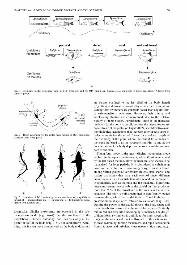
Fig. 5. Swimming modes associated with (a) BCF propulsion and (b) MPF propulsion. Shaded areas contribute to thrust generation. (Adapted from
Lindsey [10].)
Fig. 6. Thrust generation by the added-mass method in BCF propulsion.(Adapted from Webb [20].)
(a) (b) (c) (d)
Fig. 7. Gradation of BCF swimming movements from (a) anguilliform,through (b) subcarangiform and (c) carangiform to (d) thunniform mode.(Taken from Lindsey [10].)
locomotion. Similar movements are observed in the sub-
carangiform mode (e.g., trout), but the amplitude of the
undulations is limited anteriorly, and increases only in the
posterior half of the body [Fig. 7(b)]. For carangiform swim-
ming, this is even more pronounced, as the body undulations
are further confined to the last third of the body length
[Fig. 7(c)], and thrust is provided by a rather stiff caudal fin.
Carangiform swimmers are generally faster than anguilliform
or subcarangiform swimmers. However, their turning and
accelerating abilities are compromised, due to the relative
rigidity of their bodies. Furthermore, there is an increased
tendency for the body to recoil, because the lateral forces are
concentrated at the posterior. Lighthill [24] identified two main
morphological adaptations that increase anterior resistance in
order to minimize the recoil forces: 1) a reduced depth of
the fish body at the point where the caudal fin attaches tothe trunk (referred to as the peduncle, see Fig. 1) and 2) the
concentration of the body depth and mass toward the anterior
part of the fish.
Thunniform mode is the most efficient locomotion mode
evolved in the aquatic environment, where thrust is generated
by the lift-based method, allowing high cruising speeds to be
maintained for long periods. It is considered a culminating
point in the evolution of swimming designs, as it is found
among varied groups of vertebrates (teleost fish, sharks, and
marine mammals) that have each evolved under different
circumstances. In teleost fish, thunniform mode is encountered
in scombrids, such as the tuna and the mackerel. Significant
lateral movements occur only at the caudal fin (that producesmore than 90% of the thrust) and at the area near the narrow
peduncle. The body is well streamlined to significantly reduce
pressure drag, while the caudal fin is stiff and high, with a
crescent-moon shape often referred to as lunate [Fig. 7(d)].
Despite the power of the caudal thrusts, the body shape and
mass distribution ensure that the recoil forces are effectively
minimized and very little sideslipping is induced. The design
of thunniform swimmers is optimized for high-speed swim-
ming in calm waters and is not well-suited to other actions such
as slow swimming, turning maneuvers, and rapid acceleration
from stationary and turbulent water (streams, tidal rips, etc.).

7/16/2019 Http Www.ece.Eps.hw.Ac.uk Research Oceans People Michael Sfakiotakis IEEEJOE 99
http://slidepdf.com/reader/full/http-wwweceepshwacuk-research-oceans-people-michael-sfakiotakis-ieeejoe 6/16
242 IEEE JOURNAL OF OCEANIC ENGINEERING, VOL. 24, NO. 2, APRIL 1999
Ostraciiform locomotion is the only purely oscillatory BCF
mode. It is characterized by the pendulum-like oscillation of
the (rather stiff) caudal fin, while the body remains essentially
rigid. Fish utilizing ostraciiform mode are usually encased in
inflexible bodies and forage their (usually complex) habitat
using MPF propulsion [25]. Caudal oscillations are employed
as auxiliary locomotion means to aid in thrust production at
higher speeds, to ensure that the body remains adequately
rigid, or to aid prey stalking [10]. Despite some superficial
similarities with thunniform swimmers, the hydrodynamic
adaptations and refinements found in the latter are missing
in ostraciiform locomotion, which is characterized by low
hydrodynamic efficiency.
B. Body Undulations and Friction Drag
Swimming viscous drag is calculated using the standard
Newtonian equation
where is the drag coefficient (which depends on the
Reynolds number and the nature of the flow), is the wetted
surface area, and is the water density. Flexing the body to
achieve propulsion is expected to increase viscous drag by a
factor of compared to that for an equivalent rigid body, since
the motion of the propulsive elements increases their velocity
with respect to the surrounding fluid. This is known as the
“boundary layer thinning” effect, as lateral body movements
reduce the boundary layer, resulting in increased velocity
gradients and, hence, shear stress. Exactly how extensive
the increase in viscous drag is has long troubled scientists.
Originally, indirect estimations suggested (see, for example
[26] and [24]) that lies between 4 and 9. Webb in [27]
indicates that this must be a significant overestimation, placinga greater importance on the energy losses arising from recoil
forces. A value of for a swimming tadpole has been
calculated in [28] using three-dimensional (3-D) numerical
simulation, at . The rather low Re prohibits safe
application of this value of to adult fish swimming. In
the same study, it is shown that the relative amplitude of
body undulations in tadpoles is significantly larger than those
observed in fish. When the model was adapted to swim using
the kinematics of a saithe, was reduced to 1.12, stressing
the connection between large lateral motions and increased
friction drag [28].
C. Wake Structure and GenerationThe wake left behind the tail of undulatory BCF swimmers
is a staggered array of trailing discrete vortices of alternating
sign, generated as the caudal fin moves back and forth. A
jet flow with alternating direction between the vortices is also
visible [Fig. 8(c)]. The structure of the wake is of a thrust-type,
i.e., has a reversed ratational direction compared to the well-
documented drag-producing Karman vortex street. The latter
is typically observed in the wake of bluff (nonstreamlined)
objects [Fig. 8(a)] for a specific range of Reynolds numbers
(roughly ), but also in the wake of stationary
[Fig. 8(b)] or low-frequency-heaving aerfoils (see [29]).
(a) (b)
(c)
Fig. 8. The Karman street generates a drag force for either (a) bluff or (b)streamlined bodies, placed in a free stream. (c) The wake of a swimming fishhas reverse rotational direction, associated with thrust generation.
The main parameter characterizing the structure of such
wakes is the Strouhal number , defined, for a fish swimming
by BCF movements, as
where is the tail-beat frequency in hertz, is the wake
width (usually approximated as the tail-beat peak-to-peak
amplitude, and is the average forward velocity. The Strouhal
number is essentially the ratio of unsteady to inertial forces.
Triantafyllou et al. [29] concluded that, in oscillating foils,
thrust development is optimal for a specific range of St (namely
). Existing data on a number of fish species
revealed that, for high-speed swimming, their calculated St
values lie within this predicted range. Interestingly, this was
valid for species representing not just thunniform (traditionally
associated with oscillating foils) but also subcarangiform and
carangiform modes, at a range of . Theseresults have placed increased significance to vorticity effects
and established the Strouhal number as a prominent factor
when analyzing BCF modes. Detailed data on the morphology
of the wave shed behind a mullet (swimming at )
can be found in [30].
The generation mechanism of this wake structure is still
unclear, as a number of contradicting hypotheses have been
put forth. Lighthill [24] and Videler [18] support that the
reversed Karman street results exclusively from the tail move-
ments. This wake structure has indeed been observed behind
oscillating foils that were not attached to a body (see, for
example, [31]). Rosen [32] was among the first to conduct flow
visualization experiments of carangiform fish and observedattached vortices being generated by the anterior half of the
fish body. He proposed a “vortex peg” mechanism, whereby
fish thrust their body against these vortices, extracting their
rotational energy to move forward. Fully formed attached vor-
tices have not been observed in the more recent visualization
experiments. Rather, suction and pressure zones appear in the
flow pattern (Fig. 9).
Muller et al. supported an “undulating pump” mechanism
whereby these zones create a circulating flow around the
inflection points of the body. The circulating flow propagates
along the body, and upon reaching the caudal fin, it interacts

7/16/2019 Http Www.ece.Eps.hw.Ac.uk Research Oceans People Michael Sfakiotakis IEEEJOE 99
http://slidepdf.com/reader/full/http-wwweceepshwacuk-research-oceans-people-michael-sfakiotakis-ieeejoe 7/16
SFAKIOTAKIS et al.: REVIEW OF FISH SWIMMING MODES FOR AQUATIC LOCOMOTION 243
Fig. 9. The flow field around the body of a carangiform swimmer, asobtained from PIV data. The symbols P and S correspond to pressure andsuction zones that form the basis of the “undulating pump” mechanism.(Adapted from Muller et al. [30].)
with the bound vortices created by the tail movements, forming
the discrete vortices shed in the wake. Based on their particle
image velocimetry (PIV) data, the authors concluded that about
a third of the total energy shed to the water is provided by the
anterior body.
A similar mechanism is proposed by Triantafyllou and
Triantafyllou [33] as a means of recapturing energy and
reducing the apparent drag of swimming, by at least 50%
[5]. This could provide an explanation to “Gray’s Paradox”that has long troubled scientists. Gray [34] estimated the
power requirements for a cruising dolphin, assuming that
its drag can be approximated by that of a rigid model and
considering turbulent flow. The calculations indicated that the
power required exceeded the estimates of muscle power output
by a factor of seven, thus the paradox. Despite the numerous
adjustments and corrections of Gray’s original estimations
and the varied explanations suggested (see [11]–[13], [21]),
no definite conclusions have been drawn on the matter. The
new hypothesis is supported by efficiency measurements of an
articulated robot swimming by body undulations (the “Robo-
Tuna”—see [5] and [6]), flow visualizations of swimming fish
[35], as well as experiments and simulations with oscillatingfoils extracting energy from incoming vortices [35]–[37]. The
implication of this theory is that the apparent swimming drag
is actually lower for an undulating body than that of the
rigid equivalent. This is in complete contrast to the traditional
assumptions that estimate the apparent swimming drag to be
three to five times that of the rigid-body equivalent, due to
the increased friction drag and inertial recoil energy losses
associated with BCF undulatory motions. There is a need to
reexamine existing data, assumptions, and trends observed in
nature and assess them in the context of these new theoretical
developments.
Vorticity control mechanisms were originally proposed in
the early 1970’s in the context of fish schooling behavior oftenobserved in scombrids. As each vortex is shed by individual
swimming fish, it induces a water motion that is opposite
to the swimming direction immediately behind the fish, but
in the swimming direction at the sides [Fig. 8(c)]. Therefore,
a fish situated laterally midway between the two fish of the
preceding column (Fig. 10), rather than directly behind one of
them, avoids having to overcome increased incoming flow. A
“channeling effect” has also been suggested, provided the fish
stay close together, to utilize the favorable flow at the sides
of the vortex-street. The advantage is greater when fish in the
same column swim in antiphase with the neighbors. These
Fig. 10. Plan view of a horizontal layer of a fish school, showing itsdiamond-shaped building block structure. The configuration is described bythe wake width A , the vortex spacing L , and the lateral distance H amongstfish of the same column. (Adapted from Weihs and Webb [16].)
requirements point to an elongated diamond-shape pattern as
the basic optimum structure in fish schools (Fig. 10). Evidence
from aerial photographs of schooling scombrids support this
prediction. The hydrodynamic benefits of schooling seem to
vary for each column, as partial or complete cancellation of
vortices can occur. Magnuson [11] estimates average energy
savings of 10%–20% from schooling. Details can be found in
[11], [16], and [38].
D. Mathematical Analysis
Scientists from varying backgrounds have attempted to
formulate mathematical models to describe the observed kine-
matics of fish. Work has been hindered by the inherent
variability and complexity encountered in natural processes,
limiting the accuracy and repeatability of experiments and
measurements compared to other areas of engineering.
Early “resistive” hydrodynamic models (see, for example,
[39]) were based on a quasi-static approach that uses steady-
state flow theory to calculate the fluid forces for sequential
“frames” of the fish’s motion. Their applicability is restricted
to low Reynolds numbers, due to neglecting inertial forces
and the oversimplified assumptions concerning fish motions
and body shapes. Later models dealt with more realistic fish-
type motions, assuming an inviscid (frictionless) fluid. Wu
[40] originally developed a two-dimensional (2-D) waving
plate theory, treating the fish as an elastic plate. Along with
the “slender body theory” that stems from aerodynamics, it
formed the basis for Lighthill’s elongated-body theory [41],
[42], which is well suited to subcarangiform and carangiform
modes. The flows induced by the undulating body are assumedto cancel out over a tailbeat cycle and the mean thrust is
estimated from the trailing edge kinematics. The original
theory was extended by Lighthill in [43] to cater for fish
motions of arbitrary amplitude, leading to the large-amplitude
elongated-body theory that is better suited to carangiform
swimming, where the lateral motions of the caudal fin are
large. Mechanical thrust power for a fish swimming at an
average speed is calculated [27] as

7/16/2019 Http Www.ece.Eps.hw.Ac.uk Research Oceans People Michael Sfakiotakis IEEEJOE 99
http://slidepdf.com/reader/full/http-wwweceepshwacuk-research-oceans-people-michael-sfakiotakis-ieeejoe 8/16
244 IEEE JOURNAL OF OCEANIC ENGINEERING, VOL. 24, NO. 2, APRIL 1999
where
is the added mass per unit length ( is the trailing edge span
and the density of the water), while
is the rms value of the lateral speed of the trailing edge (
is the frequency of the caudal fin oscillations and is their
amplitude). The velocity given to the water at the trailing
edge is obtained as
where is the velocity of the propulsive wave. Finally, is the
angle of the trailing edge to the lateral plane of motion. Filmed
sequences of the swimming fish are used to determine these
parameters. The hydromechanical efficiency is calculated as
As the above equation shows, is never less than 0.5 (as
, while for ).
For examples of practical application of the large-amplitude
elongated body, see [44] and [45]. Lighthill’s work has been
further refined to include the effects of body elasticity [46],
recoil movements [47], centerline curvature, and the interac-
tion of the caudal fin with the vortex sheets shed from dorsal
fins [48]. The importance of body thickness effects in relation
to thrust and drag have been studied in [49] and [50]. All
these analytical approaches have shed significant light on the
morphology and swimming mode of fish. Large-amplitudeelongated-body theory has also been used by Weihs to study
the hydrodynamics of BCF turning maneuvers [51] and fast
starts [52]. The outlines of large-amplitude elongated-body
theory found in [44] and [18] are recommended as introductory
texts on the subject. Linear and nonlinear extensions of the
waving plate theory have also appeared in Tong et al. [53]
and Root and Long [54]. The latter allows the analysis of fast
starts as well as steady swimming.
Elongated-body theory cannot be applied to thunniform
mode, because the shape of the caudal and pectoral fins
violates the fundamental assumption of slenderness. The the-
ories that have been developed stem from work on oscillating
aerofoils and consider the caudal fin independent from the restof the fish body. These are presented separately in Section
III-E. Models that integrate viscous and pressure drag with
acceleration reaction should provide further insights, particu-
larly for anguilliform locomotion, where viscous forces seem
to play a significant role. This need has been set forth early [24]
and, in principle, viscous and inertial forces can be calculated
separately, the latter estimated using inviscid theory. Charac-
terizing the flow around the fish body is very complicated,
rendering the formulation of such a model problematical and
possibly impractical for application to and validation by actual
data [21].
In another hydrodynamic approach, the energy costs of
swimming are estimated indirectly by calculating the energy
shed into the wake, based on the size and circulation of the
discrete vortices [30]. Application of this method to PIV data
obtained for a swimming mullet yielded a propulsive efficiency
greater than 90%.
Concerning ostraciiform locomotion, Blake in [55] consid-
ered the thrust force generated by a rigid tail oscillating, while
the fish body is held straight. He applied both elongated-body
theory and a reactive model of a finite circular oscillating
disc moving in its own plane and in a perfect fluid, found in
[56]. Propulsive efficiencies were calculated to be around 0.5,
considerably lower than those obtained for undulatory BCF
modes.
As a final remark, numerical studies involving computa-
tional fluid dynamics (CFD) techniques have lately appeared
in literature, exploiting the increased power of computers. The
objective is to calculate the flow patterns and pressure field
around the undulating fish body and/or caudal fin by solving
the Navier–Stokes equations in order to determine the forces
generated as a result of the momentum changes. The potentialbenefits in understanding the way the swimming body interacts
with water are immense, as many of the assumptions found
in analytical methods can, in theory at least, be dispensed
with. The increased computational task for such simulations
meant that initial attempts assumed 2-D flows or simplified
movements [57]. Recently. 3-D CFD models have emerged,
utilizing advanced computational techniques and the power of
supercomputers [28], [58], [59].
E. Elements of Lunate Tail Propulsion
The thunniform mode being a highly efficient method of
swimming has attracted much recent interest, due to its poten-tial for providing artificial systems with advanced propulsor
designs. The benefits have already been demonstrated in the
form of the RoboTuna robotic fish [5] that was shaped after an
actual tuna and combined oscillating foil tail movements with
carangiform body kinematics (i.e., presenting more extensive
undulations than those encountered among actual scombrids).
Mean propulsive efficiencies as high as 91% have been re-
ported for the RoboTuna. Its success spawned further work
in the area of swimming robots [1]. In [4], the use of a dual
flapping foil device for propulsion and/or maneuvering of a
rigid cylinder-shaped body is demonstrated, investigating both
a “clapping” and a “waving” mode of operation. Work has
also been directed at the prospect of applying oscillating foilpropulsion to traditional sea-surface vessels (see [2] for a list
of references).
Fish swimming in the thunniform mode are characterized
by a stiff caudal fin, shaped like a tapered hydrofoil of a
moderate sweepback angle with a curved leading edge and
a sharp trailing edge [Fig. 11(a)]. The caudal fin performs
a combination of pitching and heaving motions, tracing an
oscillating path as the fish moves forward, characterized by
a peak-to-peak amplitude , a tail-beat frequency , and a
wavelength [Fig. 11(b)]. There are very small lateral move-
ments of the body, mainly concentrated near the penduncle

7/16/2019 Http Www.ece.Eps.hw.Ac.uk Research Oceans People Michael Sfakiotakis IEEEJOE 99
http://slidepdf.com/reader/full/http-wwweceepshwacuk-research-oceans-people-michael-sfakiotakis-ieeejoe 9/16
SFAKIOTAKIS et al.: REVIEW OF FISH SWIMMING MODES FOR AQUATIC LOCOMOTION 245
Fig. 11. (a) Lateral view of caudal fin shape for thunniform swimmers, showing span b , chord c , pitching axis position d , sweepback angle 3 and surface areaS
c
. (b) Trail of an oscillating caudal fin showing amplitude A , wavelength , feather angle , and attack angle of the fin. (Adapted from Magnuson [11].)
area. As the fin moves along this trail, its forward velocity
is the same as that of the fish, while its lateral velocity
changes in time. Other important parameters of its motion
include the angle of attack (with respect to its trail) andthe feathering angle [Fig. 11(b)]. Feathering is the angle
between the fin trail and the overall path of the fish. Both
and change as the caudal fin sweeps laterally in order to
obtain maximal thrust during the whole of the fin-beat cycle.
Detailed data from several references on all these variables for
the scombrids fish family have been gathered in [11], where
tail-beat frequencies as high as 14.5 Hz are documented for
a 40-cm-long Kawakawa (swimming at a speed of 8.2 BL/s,
). Thrust is obtained by the lift force acting
on the oscillating fin surface and by leading-edge suction, i.e.,
the action of the reduced pressure in the water moving around
the rounded leading edge of the caudal fin. The developed
thrust and the propulsive efficiency generally depend on thefollowing parameters:
1) the aspect ratio (AR) of the caudal fin. This is defined
as the fin span squared, divided by the projected fin
area [Fig. 11(a)]
High aspect ratio fins lead to improved efficiency,
because they induce less drag per unit of lift or thrust
produced. In thunniform swimmers, AR values range
from 4.5 to about 7.2.
2) the shape of the caudal fin, as it is defined by the
sweepback angle and the curvature of its leadingedge [Fig. 11(a)]. A curved leading edge is beneficial,
because it reduces the relative contribution of leading-
edge suction to the total thrust, avoiding boundary layer
separation for high thrust values [11].
3) the fin stiffness. The benefit of a higher degree of stiff-
ness (achieved by fusing the many fin-rays consisting
the caudal fin) is increased thrust generation capability,
with only a relatively small drop in efficiency [11].
4) the oscillatory motions of the fin.
To study the effects of 4) on thrust production, three factors
have traditionally been considered in the models developed
for lunate tail propulsion: the reduced frequency and the
proportional feathering parameters, along with the position of
the pitching axis [defined by in Fig. 11(a)]. For a thunniform
swimmer, the reduced frequency represents the ratio of thetime to swim a distance equal to the caudal fin chord (usually
calculated as ) to the tailbeat period
The proportional feathering parameter , originally proposed
by Lighthill in [24], is defined as the ratio of slopes between
and and can be computed [12] as
where is the angle of attack in radians (the slope of ),
the maximum lateral velocity of the fin, and is the
swimming speed. Values of between 0.6 and 0.8 have beencalculated by Lighthill [60] to yield optimal combinations of
leading-edge suction and hydromechanical efficiency.
Lighthill [42] was the first to apply a simple linear 2-D
(i.e., for ) wing theory on lunate tail propulsion.
The fluid is assumed inviscid and irrotational, and potential
theory is used to calculate the thrust for small-amplitude
oscillations. In his optimization analysis, Wu [61] calcu-
lated that efficiencies close to unity are attainable in such
a 2-D model. A large-amplitude 2-D theory based on the
impulse approach was developed by Chopra [62]. Extension
to three dimensions (confined to rectangular wings and small-
amplitude oscillations) based on the vorticity distribution
was made by Chopra in [63]. Chopra and Kambe used a3-D unsteady lifting-surface theory in [64] to study thrust
production from a variety of different wing shapes. Lan
also considered a 3-D problem in [65], where an unsteady
quasi-vortex lattice method is used. All these models assume
rigid tails. The effects of passive chordwise flexibility of the
caudal fin performing large-amplitude motions for the 2-D
case were studied by Katz and Weihs in [66]. A linearized
low-frequency unsteady lifting-line theory was applied by
Ahmadi and Widnall in [67]. A strip theory considering small-
amplitude pitching motions was developed by Bose and Lien
in [68] to calculate the hydrodynamic performance of a fin

7/16/2019 Http Www.ece.Eps.hw.Ac.uk Research Oceans People Michael Sfakiotakis IEEEJOE 99
http://slidepdf.com/reader/full/http-wwweceepshwacuk-research-oceans-people-michael-sfakiotakis-ieeejoe 10/16
246 IEEE JOURNAL OF OCEANIC ENGINEERING, VOL. 24, NO. 2, APRIL 1999
whale’s flukes that operate on a similar principle. Cheng
and Murillo developed a 3-D theory considering a curved
centerline for the caudal fin (relating to the term “lunate”)
in [69] that was subsequently applied in [70] to determine the
influence of the sweepback angle and the centerline curvature.
Three-dimensional triangular hydrofoils were analyzed by
Cheng et al. using the unsteady vortex ring method in [71].
A summary of the developed hydromechanical theories can
be found in [72]. Recently, a time-domain panel method
was used by Liu and Bose [73] to study the effects on
propulsive efficiency of 3-D foils with spanwise flexibility.
Most of the above theories assume a planar vortex wake
without considering the rotational vortical patterns developed,
as shown in Fig. 8.
The wake theories of oscillating foil propulsion developed
by Triantafyllou et al. [29], [31] consider the Strouhal number
and the maximum angle of attack , based on their di-
rect relevance to the thrust coefficient and the wake dynamics.
The conditions for optimal thrust production are summarized
in [31] as follows.
1) The Strouhal number is in the range of .2) The maximum angle of attack is between
.
3) The ratio of the heave amplitude over the chord length
should be of order one.
4) For , the pitching movement should lead the
heaving motion by about 75 .
Research has also been performed on the elastic properties
of the caudal fins of cetaceans [74] and the advantages
involved in reducing the energy requirements of swimming
robots [75]. The development of artificial propulsion systems
based on oscillating foils requires reformulating the above
theories to derive dynamic models of the foil, needed for the
control system design (for examples, see [75] and [76]).
IV. MEDIAN /PAIRED FIN UNDULATIONS
A. General
Undulating fins are routinely used by many fish as auxiliary
propulsors, as well as for maneuvering and stabilization. They
can also provide adequate thrust to be used as the sole means of
locomotion, at generally low speeds (below 3 BL/s). The fins
of teleost fish consist of the fin-rays that have varying span and
stiffness and a flexible membrane connecting them together.
In median fins, a set of muscles (usually six) for each fin-
ray provide the latter with two degrees-of-freedom movementcapability, while it has been suggested that certain fish can
actively bend the rays of their median fins. Paired fins have
an even more complex muscular system, enabling movements
such as rotations of individual finrays. The literature on
the structure and properties of teleost fins is reviewed in
[10] and [18]. Their versatility has played a key role in
the development of the undulatory MPF modes [Fig. 5(b)],
presented next.
Rajiform mode is found in fish such as rays, skates, and
mantas, whose swimming has been likened to the flight
of birds. Thrust generation involves the passing of vertical
undulations along the pectorals that are very large, triangular-
shaped, and flexible. The amplitude of the undulations in-
creases from the anterior part to the fin apex and then tapers
again toward the posterior. The fins may also be flapped up
and down.
Similarly, in diodontiform mode, propulsion is achieved by
passing undulations down broad pectoral fins. Up to two full
wavelengths may be visible across the fins, while undulations
are often combined with flapping movements of the fin as a
whole.
In amiiform mode, swimming is by undulations of a (usually
long-based) dorsal fin, while the body axis is in many cases
held straight when swimming. The best examples of this
characteristic are found among the African freshwater electric
eels. The anal and caudal fins are missing, while the dorsal fin
extends along most of the body length, tapering to a posterior
point, and exhibits a large number of fin-rays (up to 200).
Gymnotiform mode can be considered as the upside-down
equivalent of amiiform mode, since propulsion is obtained
by undulations of a long-based anal fin. The dorsal fin is
usually absent and the body is again held straight duringswimming. This tendency found among electric eels (using
either amiiform or gymnotiform mode) for a rigid body during
swimming has long been considered a necessity, due to the
electrosensory system they posses. However, it may also be
connected to the absence of friction drag increase associated
with undulatory movements (see Section IV-C).
Finally, in balistiform locomotion, both the anal and dorsal
fins undulate to generate the propulsion forces. This is seen
mainly in the family Balistidae (e.g., the trigger fish). A
typical characteristic is that their median fins are usually
inclined relative to each other, while the body is usually flat
and compressed laterally. These design features have been
associated with enhanced propulsion efficiency.
B. Kinematics and Vector Analysis
According to the qualitative description of Breder and
Edgerton in [77], the thrust produced by an undulating fin
can be analyzed using two components: a force normal to
the fin base due to the simple oscillation of the fin-rays, and
a force parallel to the fin base, resulting from the passage
of the wave along the fin (Fig. 12).
This vector analysis has been verified experimentally (see,
for example, [78]) and can be applied to most undulatory MPF
modes, providing insights to the locomotory habits of the fish
utilizing them. does not contribute to thrust when the finbase is parallel to the body axis. Therefore, unless it serves
for buoyancy compensation, it will induce pitching couples for
median fin undulations and lead to increased energy losses.
Observation reveals that, for most of the electric eels (that
swim in either the amiiform or the gymnotiform mode), the
fin base is inclined to the horizontal body axis to ensure that
the resultant vector is (or can be) parallel to the body axis
to avoid these energy losses [Fig. 13(a) and (b)]. This is even
more pronounced in the balistiform swimmers of the Balistidae
family, in which the anal and dorsal fins are characteristically
inclined to each other, so that all force components of the

7/16/2019 Http Www.ece.Eps.hw.Ac.uk Research Oceans People Michael Sfakiotakis IEEEJOE 99
http://slidepdf.com/reader/full/http-wwweceepshwacuk-research-oceans-people-michael-sfakiotakis-ieeejoe 11/16
SFAKIOTAKIS et al.: REVIEW OF FISH SWIMMING MODES FOR AQUATIC LOCOMOTION 247
(a) (b)
(a)
Fig. 12. Vector analysis of an undulating fin. (a) A single fin-ray oscillating
exerts an upward thrust. (b) When many fin-rays are connected via a flexiblemembrane (plan view), additional forces are exerted as indicated by the black arrows. Their resultant is parallel to the fin base. (c) Perspective view of an undulating fin, showing both force vectors. (Adapted from Breder andEdgerton [77].)
(a)
(b) (c)
Fig. 13. Diagrams relating morphology to how the vector components of undulating fins could be combined to yield a net forward thrust for (a) anamiiform, (b) a gymnotiform, and (c) a balistiform swimmer.
propulsive waves combine to produce a net forward thrust
[Fig. 13(c)]. A significant advantage of this arrangement is
that elaborate maneuvering can be achieved by varying the
individual force components of the median fins and direct
the resulting force vector with precision. Breder and Edgertonobserved this high degree of maneuverability for the seahorse
[77] which swims exclusively by undulations of its dorsal and
anal fins. They identified a number of physical and behavioral
factors that can alter the relative magnitude of the parallel and
normal force components. Physical factors include variations
in the interdistance, length, and flexibility of the individual
fin-rays. Behavioral factors affect the amplitude, wavelength,
and phase differences along the fin and in time. The fin-rays
also perform small longitudinal as well as lateral movements,
and they tend to be held like an open fan. The musculature
supporting the seahorse fins is flexible and strong enough to
provide additional functionality; Blake [78] observed that the
fins can change their long axes relative to the body axis,
as well as move parts of the fin relative to others. These
abilities are utilized during turn maneuvers to compensate for
the inflexible body of the seahorse. Also, the entire fin may be
held at various angles to the body, allowing it to be deflected
far to one side and undulated in that position. Finally, most
undulatory median fin swimmers are able to swim backward
just as effectively as forward by simply reversing the direction
of propagation of the propulsive wave [79], [80].
In undulating pectoral fins, the vertical force components
are lateral to the fish body and create yawing couples that
are generally cancelled out for symmetrical movements of
the fins. Powered maneuvers can be obtained by asymmetric
movements and different phase relationships in the undulating
paired fins [81].
Apart from swimming, fish utilize fin undulations exten-
sively for hovering in mid-water. Small corrective forces are
generated by the fins to compensate for disturbances due to
pressure variations, minor sudden currents, or even the jet-
effect of the respiratory flow [26].
C. Mathematical Analysis
A simple method used to calculate the hydromechanical
efficiencies for undulatory fin swimmers is the actuator-disc
theory, a special application of the momentum principle in
fluid dynamics. The mechanism operating on the fluid (in this
case, an undulating fin) is reduced to an idealized device
(actuator disc) that generates a pressure rise in the fluid
passing through it. The thrust force can be calculated by
integrating the pressure rise over the whole disc. The main
advantage of this approach is that the fin is regarded as a
“black box,” requiring no detailed knowledge of its kinematics.However, the assumptions involved can be quite restrictive.
For applications of the actuator-disc theory to fish propulsion
and hovering, along with discussions on its limitations, see
[82]–[84].
The similarity of the waveforms observed in median fins
and those found in the undulating bodies of BCF swimmers
has encouraged the application of large-amplitude elongated-
body theory to the undulatory median fin propulsion modes.
The initial work reported in [80], [84], and [85] was extended
in a series of papers [86]–[89] by Lighthill and Blake. It is
there shown that, for rigid deep-bodied fish, the momentum
shed into the water can be increased by a factor of about
three, compared to the momentum expected by the movementof the fins “on their own.” This increment does not apply
to the shedding of “unproductive” energy into the wake.
Furthermore, the minimization of lateral forces, due to the
fact that they largely cancel out over the fin length, means that
the fish body can remain rigid, avoiding increases in viscous
drag. These factors all combine to significantly increase the
overall efficiency of undulating median fin propulsion. For
a speed range from 0.2 to 5 BL/s (corresponding to a
from 10 to 10 ), Blake [80] calculated a propulsive efficiency
between 0.7 and 0.9 for electric eels and knifefishes. The ap-
plication of the latest wake theories developed for undulatory

7/16/2019 Http Www.ece.Eps.hw.Ac.uk Research Oceans People Michael Sfakiotakis IEEEJOE 99
http://slidepdf.com/reader/full/http-wwweceepshwacuk-research-oceans-people-michael-sfakiotakis-ieeejoe 12/16
248 IEEE JOURNAL OF OCEANIC ENGINEERING, VOL. 24, NO. 2, APRIL 1999
BCF propulsion to gymnotiform and amiiform locomotion
presents an interesting field of research that, along with flow
visualization experiments, could determine whether vorticity
control mechanisms are employed by fish swimming in these
modes.
Finally, rajiform locomotion has been analyzed by Daniel
using a combination of unsteady aerofoil theory and blade-
element theory in [90], where the significance of unsteady
effects and wing shape in thrust generation is demonstrated.
V. MPF OSCILLATIONS
A. General
Fin oscillations usually involve short-based median or
paired fins. In tetraodontiform mode, the dorsal and anal fins
are flapped as a unit, either in phase or alternating to achieve
propulsion. The ocean sunfish is an extreme example of
tetraodontiform swimmer: it has virtually no caudal fin or body
musculature and propels itself by synchronized oscillations of
its very high dorsal and anal fins. Tetraodontiform mode
can be viewed as a continuation of balistiform mode, wherethe wavelength of the propulsive wave is very large, and,
consequently, the individual fin-rays oscillate more or less
in phase.
In labriform mode, propulsion is achieved by oscillatory
movements of the pectoral fins. Due to the large variability
of these movements, as well as the significance of pectoral
fin swimming amongst fish and the potential for building
stabilization/maneuvering devices based on them (see, for
example, [7] and [91]), the following section is dedicated to a
more detailed discussion of labriform locomotion.
B. Labriform SwimmingSwimming using the pectoral fins is widespread among
teleost fish, but only recently has it received scientific atten-
tion. This is largely because of the difficulty in observing and
analyzing the fin kinematics due to the speed, variability, and
complexity of the movements performed (flapping, rotations
and undulations), as well as the transparent nature of the
fin membrane. Recently, a number of sophisticated filming
techniques have evolved, enabling the acquisition of detailed
kinematic data, that can help us gain a better understanding of
the hydrodynamic forces involved.
Blake [82] identified two main oscillatory movement types
for the pectoral fins: 1) a “rowing” action (drag-based labri-
form mode) and 2) a “flapping” action, similar to that of bird wings (lift-based labriform mode). According to Vogel
[13], drag-based methods are more efficient at slow speeds,
when the chordwise flow over the fin is small, while lift-based
methods are more efficient at higher speeds. Later observations
(see [91] and [92]) emphasized the importance of acceleration
reaction in thrust generation. They also indicate that pectoral
fin movements are usually very complicated owing to the
highly flexible character of the membrane and the fin-rays,
as well as to the hydrodynamic interactions of the fins with
the moving water and the fish body. Thus, fish rarely exhibit
a clearly rowing or flapping movement. Instead, they use a
(a) (b)
Fig. 14. Diagram showing the fin positions and attack angles during (a) thepower stroke and (b) the recovery stroke for a fish swimming in drag-basedlabriform mode. (Adapted from Blake [84].)
combination of them that generally varies with speed. Undula-
tions are also often passed along the fins (diodontiform mode),and the great diversity of movements attainable can generate
thrust in almost any direction, achieving high maneuverability.
The complexity of the pectoral fin motions is illustrated in
the detailed 3-D kinematic data recently available [91], [92],
[93]. Comprehensive reviews of pectoral fin swimming can be
found in [18] and [91]; the latter discusses a number of issues
pertinent to the design of artificial fins for use in underwater
vehicles. To understand the basics of thrust generation in
pectoral fin movements, it is helpful to go back into the original
studies of the purely drag- and lift-based labriform locomotion,
for which mathematical models have been easier to develop.
1) Drag-Based Mode: Blake presents kinematic data and
a mechanical analysis of drag-based labriform locomotion in[94] and [95], as it is utilized by angelfish for an extensive
range of swimming speeds. The fins usually have a short base
that forms a high angle with the main axis. Rowing action con-
sists of two phases [94]: the power stroke, when the fins move
posteriorly perpendicular to the body at a high attack angle
and with a velocity greater than the overall swimming speed
[Fig. 14(a)], and a recovery stroke, when the fins are “feath-
ered” to reduce resistance and brought forward [Fig. 14(b)].
Thrust is generated due to the drag encountered as the fin is
moved posteriorly, as well as due to the acceleration reaction
of the water being rapidly hauled at the initial part of the power
stroke. Since thrust is only produced during the power stroke, it
is discontinuous. This is in contrast to BCF propulsion, wherea usefully directed thrust force is generated over most of the
tail-beat cycle.
Blade-element theory has been applied to drag-based labri-
form propulsion, whereby the pectoral fins are divided into a
number of rigid sections, each inclined at an angle to the inci-
dent flow. According to the results obtained for an 8-cm-long
angelfish specimen swimming at about 0.5 BL/s, the outermost
40% of the fin area produces over 80% of the total hydrody-
namic force. A propulsive efficiency of 16% for the complete
rowing stroke is derived using the same calculations [95].
A simple hydromechanical model developed in [96] predicts

7/16/2019 Http Www.ece.Eps.hw.Ac.uk Research Oceans People Michael Sfakiotakis IEEEJOE 99
http://slidepdf.com/reader/full/http-wwweceepshwacuk-research-oceans-people-michael-sfakiotakis-ieeejoe 13/16
SFAKIOTAKIS et al.: REVIEW OF FISH SWIMMING MODES FOR AQUATIC LOCOMOTION 249
that, for a given planform area, triangular fins will create less
interference drag over the fish body than square or rectangular
ones. This is in accordance with the actual fin shape observed
in drag-based labriform swimmers. More recently, Kato and
Inaba used the unsteady vortex lattice method to calculate
the hydrodynamic forces on a rigid pectoral fin model [3]
in drag-based labriform mode. The propulsive efficiencies
calculated do not exceed 10%, a result in accordance with
their experimental measurements and the predictions of blade-
element theory. Despite these low values, Blake suggested [94]
that rowing propulsion is more efficient for slow swimming
than BCF modes, the efficiency of which falls off rapidly
for decreasing speed. There is evidence for that in nature, as
many fish use labriform locomotion for slow-speed swimming,
switching to BCF propulsion at higher speeds. In [97], the
velocity at which this transition occurs for a certain species
( Notothenia Neglecta, average adult length 28 cm) is quoted
as 0.8 BL/s. However, the use of labriform locomotion at
low speed could be attributed to nonenergetic factors, such as
higher maneuverability or being less conspicuous to predators.
2) Lift-Based Mode: Lift forces are generated in the planeperpendicular to the direction of the fin motion, whereas drag
forces appear in the plane of the fin motion. As a result, in
lift-based labriform mode, for the pectoral fins to propel the
fish forward, they have to move up and down in a plane that
is roughly perpendicular to the main axis of the fish’s body.
This implies that no recovery stroke is necessary and lift can
be generated during both the upstroke and the downstroke.
Additionally, lift forces can be an order of magnitude greater
than the drag forces generated by a fin of the same area.
Thus, lift-based fins can generate larger, more continuous,
and more efficient thrust than fins performing rowing motions
(see [91] for relevant data). The fin shapes for lift-based
labriform swimmers tend to differ from those using drag-basedmechanics. One reason is the need to minimize the crossflow
around the fin tip that decreases lift and increases drag. As
a result, lifting fins tend to be diamond-shaped, with a high
aspect ratio and tapered at both ends, while their base usuallyforms a small angle relative to the main axis [20].
Kinematics obtained by Webb [98] for the pectoral fin
propulsion of the seaperch have since been used to outline
lift-based labriform mode, although the movements performed
cannot be considered a pure flapping; they are, however,
simpler and more tractable than those found in more recent
data (see [99] and [97]). Along with oscillating in a dorso-
ventral motion, the pectoral fins of the seaperch pass a wave
back over their length as a result of phase lags in the movementof the individual fin rays. The wavelength of this wave varies
with swimming speed, resulting in phase lags from about (for
velocities below 2 BL/s) to about (at higher velocities)
between the leading and trailing edges of the fin.
Webb divided the fin-beat cycle in the seaperch into ab-
duction [Fig. 15(a)], adduction [Fig. 15(b)], and refractory
[Fig. 15(c)] phases. The terminology has been since adopted,
although inconsistencies concerning the movements charac-
terizing each phase do appear in the literature. Generally,
during abduction, the fin is moved away from the body
and downwards. It is then brought back to the body surface
(a) (b) (c)
Fig. 15. Dorsal view of the fin movements in the lift-based labriform modefor the seaperch. The diagrams show how the fin trailing edge (thin line) lagsbehind during (a) the abduction, (b) the adduction, and (c) the refraction of the leading edge (thick line). The fish used had an average length of 14.3 cmand swam at 1.2 BL/s. (Adapted from Webb [98].)
(adduction phase) and, during refraction, the fin is orientatedto its original position by rotation of the leading edge. Due to
the subtlety of these movements, the angle of attack for the fin
changes during each phase. As a result, the lift forces generated
have an elevation as well as a thrust component that causes the
body to move up and down during normal forward swimming.
Additionally, thrust forces will be generated discontinuously
because of the pattern of fin-beat and refractory phases.
Between abduction and adduction, and during the refractory
phase, no lift-based thrust is generated. Webb estimated a
propulsive efficiency between 0.6 and 0.65, for it has been
suggested in [99] that some small thrust could result from
a jet propulsion effect during refraction as water is being
displaced out of the decreasing space between the fins andthe body. If present, its effect should be minimal, and the fish
generally tends to accelerate during abduction and adduction
and to decelerate in between. The net result of these motions
is that the fish body moves relative to the flow in a figure-
eight motion, whose parameters change with speed, reflecting
variations in the elevation and thrust components [98]. Recent
observations show that fish can smooth out their movements
by complimentary actions of the other fins.
A blade-element analysis of flapping pectoral fins is given
by Blake in [84]. Again, a purely lift-based labriform mode
is considered and the fin is assumed to consist of a series
of straight elements. The generalized applicability of blade-
element theory to labriform locomotion is questioned (see [92]
for a discussion), due to the curvatures and shape changes
observed for the pectoral fins when a combination of lift- and
drag-based methods is used, as is generally the case.
VI. SUMMARY
Having looked at some of the biomechanical aspects of
certain swimming modes employed by fish, one can only
marvel at the developed mechanisms and their significance in
relation to the aquatic environment. It seems highly desirable
to successfully replicate them in artificial devices. However,

7/16/2019 Http Www.ece.Eps.hw.Ac.uk Research Oceans People Michael Sfakiotakis IEEEJOE 99
http://slidepdf.com/reader/full/http-wwweceepshwacuk-research-oceans-people-michael-sfakiotakis-ieeejoe 14/16
250 IEEE JOURNAL OF OCEANIC ENGINEERING, VOL. 24, NO. 2, APRIL 1999
although the evolved designs are highly effective for the
fish adapting to their habitat, it should be kept in mind
that the locomotor methods employed cannot necessarily be
considered optimal per se. This is because their development
has always been in the context of compromises for various
activities (feeding, predator avoidance, energy conservation,
etc.). An illustrative example can be found in the seahorse,
as it is presented in [78]. The dorsal fin rays oscillate at
very high frequencies (up to about 40 Hz), compared to most
other species utilizing fin undulations for propulsion (rarely
exceeding 10 Hz). The high fin-beat frequency is related to
the short wavelength of the wave propagating along the dorsal
fin of the seahorse and is associated with reduced swimming
efficiency [83], [86]. To account for this, it has been suggested
that it actually helps the seahorse avoid potential predators
because the fin beat frequency lies beyond the fusion frequency
of the predators’ eyes, rendering the seahorse indistinguishable
from surrounding vegetation. Therefore, when considering
designs and kinematics for porting from nature to artificial
systems, the significance of these nonlocomotor factors and
the extent to which they have compromised performance needto be assessed. Some of these issues are addressed in Webb’s
recent comparative review of fish versus man-made designs
[100]. Clearly, there is much to be learned from the examples
that have evolved in fish. However, our capacity to utilize theseevolutions is very much dependent on our ability to construct
actuators and control systems that possess suitable material
and motion properties. Current efforts rely on tendon- [5] or
hydraulic-driven [1] mechanical links, shape memory alloys
[101], ionic conducting polymer film [102], and polymer-metal
composites [103], [104] as artificial muscles to implement BCF
undulations. To our knowledge, no attempt has been made
to mimic the structure of teleost fins (membrane and rays),
and existing fin-like structures are rigid approximations [3],[105].
From our perspective, we are interested in the application
of flexible actuators to the synthesis of fish propulsion mech-
anisms. In particular, the “elephant’s trunk” actuator [106],
currently under development as a finger for the AMADEUS
subsea dextrous hand [107], offers potential for simple and
robust implementation of devices based on either the thunni-
form mode or on undulating fins, for propulsive or stabilizing
action, respectively. Details of design and practical results
from the testbed under development will be the subject of
future publications.
REFERENCES
[1] J. M. Anderson and P. A. Kerrebrock, “The vorticity control unmannedundersea vehicle (VCUUV)—An autonomous vehicle employing fishswimming propulsion and maneuvering,” in Proc. 10th Int. Symp.Unmanned Untethered Submersible Technology, NH, Sept. 1997, pp.189–195.
[2] J. Czarnowski, R. Cleary, and B. Creamer, “Exploring the possibilityof placing traditional marine vessels under oscillating foil propulsion,”in Proc. 7th (1997) Int. Offshore and Polar Eng. Conf., Honolulu, HI,May 1997, pp. 76–82.
[3] N. Kato and T. Inaba, “Hovering performance of fish robot withapparatus of pectoral fin motion,” in Proc. 10th Int. Symp. Unmanned Untethered Submersible Technology, NH, Sept. 1997, pp. 177–188.
[4] P. R. Bandyopadhyay and M. J. Donelly, “The swimming hydrodynam-ics of a pair of flapping foils attached to a rigid body,” in Proc. Special
Session on Bio-Engineering Research Related to Autonomous Under-
water Vehicles, 10th Intern. Symp. Unmanned Untethered Submersible
Technology, NH, Sept. 1997, pp. 27–43.[5] D. Barrett, M. Grosenbaugh, and M. Triantafyllou, “The optimal control
of a flexible hull robotic undersea vehicle propelled by an oscillatingfoil,” in Proc. 1996 IEEE AUV Symp., pp. 1–9.
[6] D. S. Barrett, “Propulsive efficiency of a flexible hull underwatervehicle,” Ph.D. dissertation, Massachusetts Inst. Technol., Cambridge,1996.
[7] N. Kato and M. Furushima, “Pectoral fin model for manuever of
underwater vehicles,” in Proc. 1996 IEEE AUV Symp., pp. 49–56.[8] J. Jalbert, S. Kashin, and J. Ayers, “A biologically-based undulatory
lamprey-like AUV,” in Proc. Autonomous Vehicles in Mine Counter-
measures Symposium, Naval Postgraduate School, 1995, pp. 39–52.[9] I. Yamamoto, Y. Terada, T. Nagamatu, and Y. Imaizumi, “Propulsion
system with flexible/rigid oscillating fin,” IEEE J. Oceanic Eng., vol.20, pp. 23–30, 1995.
[10] C. C. Lindsey, “Form, function and locomotory habits in fish,” in Fish
Physiology Vol. VII Locomotion, W. S. Hoar and D. J. Randall, Eds.New York: Academic, 1978, pp. 1–100.
[11] J. J. Magnuson, “Locomotion by scombrid fishes: Hydromechanics,morphology and behavior,” in Fish Physiology Vol. VII Locomotion,W. S. Hoar and D. J. Randall, Eds. New York: Academic, 1978, pp.239–313.
[12] P. W. Webb, “Hydrodynamics and energetics of fish propulsion,” Bull.
Fisheries Res. Board of Canada, vol. 190, pp. 1–159, 1975.[13] S. Vogel, Life in Moving Fluids. Princeton, NJ: Princeton Univ., 1994.
[14] T. L. Daniel, “Unsteady aspects of aquatic locomotion,” Amer. Zool.,vol. 24, pp. 121–134, 1984.[15] P. W. Webb, “Simple physical principles and vertebrate aquatic loco-
motion,” Amer. Zool., vol. 28, pp. 709–725, 1988.[16] D. Weihs and P. W. Webb, “Optimization of locomotion,” in Fish
Biomechanics, P. W. Webb and D. Weihs, Eds. New York: Praeger,1983, pp. 339–371.
[17] C. M. Breder, “The locomotion of fishes,” Zoologica, vol. 4, pp.159–256, 1926.
[18] J. J. Videler, Fish Swimming. London, U.K.: Chapman & Hall, 1993.[19] P. W. Webb, “The biology of fish swimming,” in Mechanics and
Physiology of Animal Swimming, L. Maddock, Q. Bone, and J. M. V.Rayner, Eds. Cambridge, U.K.: Cambridge Univ., 1994, pp. 45–62.
[20] , “Form and function in fish swimming,” Sci. Amer., vol. 251,pp. 58–68, 1984.
[21] , “Hydrodynamics: Nonscombroid fish,” in Fish Physiology Vol.
VII Locomotion, W. S. Hoar and D. J. Randall, Eds. New York:Academic, 1978, pp. 189–237.
[22] J. H. Long, Jr., W. Shepherd, and R. G. Root, “Manueuverability andreversible propulsion: How eel-like fish swim forward and backward us-ing travelling body waves,” in Proc. Special Session on Bio-Engineering
Research Rel ated to Autonomous Underwater Vehicles, 10th Int. Symp.
Unmanned Untethered Submersible Technology, NH, Sept. 1997, pp.118–134.
[23] G. B. Gillis, “Undulatory locomotion in elongate aquatic vertebrates:Anguilliform swimming since Sir James Gray,” Amer. Zool., vol. 36,pp. 656–665, 1996.
[24] M. J. Lighthill, “Hydromechanics of aquatic animal propulsion,” Ann.
Rev. Fluid. Mech., vol. 1, pp. 413–466, 1969.[25] R. W. Blake, “On ostraciiform locomotion,” J. Marine Biol. Assoc., vol.
57, pp. 1047–1055, 1977.[26] R. McN. Alexander, Functional Design in Fishes, London, U.K:
Hutchinson Univ. Library, 1967, ch. 2.[27] P. W. Webb, “Is the high cost of body caudal fin undulatory swimming
due to increased friction drag or inertial recoil?” J. Exp. Biol., vol. 162,
pp. 157–166, 1992.[28] H. Liu, R. Wassersug, and K. Kawachi, “The three-dimensional hydro-
dynamics of tadpole locomotion,” J. Exp. Biol., vol. 200, pp. 2807–2819,1997.
[29] G. S. Triantafyllou, M. S. Triantafyllou, and M. A. Grosenbauch,“Optimal thrust development in oscillating foils with application to fishpropulsion,” J. Fluids Struct., vol. 7, pp. 205–224, 1993.
[30] U. K. Muller, B. L. E. Van den Heuvel, E. J. Stamhuis, and J. J.Videler, “Fish foot prints: Morphology and energetics of the wake behindcontinuously swimming mullet (Chelon Labrosus Risso),” J. Exp. Biol.,vol. 200, pp. 2893–2906, 1997.
[31] J. M. Anderson, K. Streitlien, D. S. Barrett, and M. S. Triantafyllou,“Oscillating foils of high propulsive efficiency,” J. Fluid Mech., vol.360, pp. 41–72, 1998.
[32] M. W. Rosen, “Water flow about a swimming fish,” China Lake, CA,US Naval Ordnance Test Station TP 2298, p. 96, 1959.

7/16/2019 Http Www.ece.Eps.hw.Ac.uk Research Oceans People Michael Sfakiotakis IEEEJOE 99
http://slidepdf.com/reader/full/http-wwweceepshwacuk-research-oceans-people-michael-sfakiotakis-ieeejoe 15/16
SFAKIOTAKIS et al.: REVIEW OF FISH SWIMMING MODES FOR AQUATIC LOCOMOTION 251
[33] M. S. Triantafyllou and G. S. Triantafyllou, “An efficient swimmingmachine,” Sci. Amer., vol. 272, pp. 40–46, 1995.
[34] J. Gray, “Studies in animal locomotion. VI. The propulsive powers of the dolphin,” J. Exp. Biol., vol. 13, pp. 192–199, 1936.
[35] J. M. Anderson, “Vorticity control for efficient propulsion,” Ph.D.dissertation, Massachusetts Inst. Technol./Woods Hole OceanographicInst. Joint Program, Woods Hole, MA, 1996.
[36] R. Gopalkrishnan, M. S. Triantafyllou, G. S. Triantafyllou, and D.Barrett, “Active vorticity control in a shear flow using a flapping foil,”
J. Fluid Mech., vol. 274, pp. 1–21, 1994.
[37] K. Streitlien, G. S. Triantafyllou, and M. S. Triantafyllou, “Efficient foilpropulsion through vortex control,” AIAA J., vol. 34, pp. 2315–2319,1996.
[38] D. Weihs, “Some hydromechanical aspects of fish schooling,” in Swim-
ming and Flying in Nature, T. Y. Wu, C. J. Brokaw, and C. Brennan,Eds. New York: Plenum, 1975, vol. 2, pp. 703–718.
[39] G. Taylor, “Analysis of the swimming of long narrow animals,” in Proc.
R. Soc. Lond. A, 1952, vol. 214, pp. 158–183.[40] T. Y. Wu, “Swimming of a waving plate,” J. Fluid Mech., vol. 10, pp.
321–344, 1961.[41] M. J. Lighthill, “Note on the swimming of slender fish,” J. Fluid Mech.,
vol. 9, pp. 305–317, 1960.[42] , “Aquatic animal propulsion of high hydromechanical effi-
ciency,” J. Fluid Mech., vol. 44, pp. 265–301, 1970.[43] , “Large-amplitude elongated-body theory of fish locomotion,” in
Proc. R. Soc. Lond. B, 1971, vol. 179, pp. 125–138.[44] C. S. Wardle and A. Reid, “The application of large amplitude elongated
body theory to measure swimming power in fish,” in Fisheries Mathe-matics, J. E. Steele, Ed. New York: Academic, 1977, pp. 171–191.[45] J. Y. Cheng and R. Blickhan, “Note on the calculation of propeller
efficiency using elongated body theory,” J. Exp. Biol., vol. 192, pp.169–177, 1994.
[46] J. Katz and D. Weihs, “Large amplitude unsteady motion of a flexibleslender propulsor,” J. Fluid Mech., vol. 89, pp. 713–723, 1979.
[47] T. Kambe, “The dynamics of carangiform swimming motions,” J. Fluid
Mech., vol. 87, pp. 533–560, 1978.[48] T. Y. Wu, “Hydrodynamics of swimming propulsion. Part 3. Swimming
and optimum movement of slender fish with side fins,” J. Fluid Mech.,vol. 46, pp. 521–544, 1971.
[49] J. N. Newman and T. Y. Wu, “A generalized slender-body theory forfish-like forms,” J. Fluid Mech., vol. 57, pp. 673–693, 1973.
[50] J. N. Newman, “The force on a slender fish-like body,” J. Fluid Mech.,vol. 58, pp. 689–702, 1973.
[51] D. Weihs, “A hydromechanical analysis of fish turning manuevers,” inProc. R. Soc. Lond. B, 1972, vol. 182, pp. 59–72.
[52] D. Weihs, “The mechanism of rapid starting of slender fish,” Biorheol-ogy, vol. 10, pp. 343–350, 1973.
[53] B. G. Tong, L. X. Zhuang, and J. Y. Cheng, “The hydrodynamic analysisof fish propulsion performance and its morphological adaptation,” inSadhana-Academy Proc. in Eng. Sciences, 1993, vol. 18, pp. 719–728.
[54] R. G. Root and J. H. Long, Jr., “A virtual swimming fish: Modelingcarangiform fish locomotion using elastic plate theory,” in Proc. Special
Session on Bio-Engineering Research Related to Autonomous Under-
water Vehicles, 10th Intern. Symp. Unmanned Untethered Submersible
Technology, NH, in addendum, Sept. 1997.[55] R. W. Blake, “Mechanics of ostraciiform propulsion,” Can. J. Zool.,
vol. 59, pp. 1067–1071, 1981.[56] E. H. Smith and D. E. Stone, “Perfect fluid forces in fish propulsion,”
in Proc. R. Soc. Lond. A, 1961, vol. 261, pp. 316–328.[57] J. C. Carling, G. Bowtell, and T. L. Williams, “Swimming in the
lamprey: Modeling the neural pattern generation, the body dynamics andthe fluid mechanics,” in Mechanics and Physiology of Animal Swimming,
L. Maddock, Q. Bone, and J. M. V. Rayner, Eds. Cambridge, U.K.:Cambridge Univ., 1994, pp. 119–132.
[58] T. Nakaoka and Y. Toda, “Laminar flow computation of fish-like motionwing,” in Proc. 4th Int. Offshore and Polar Eng. Conf., Osaka, Japan,Apr. 1994, pp. 530–538.
[59] R. Ramamurti, R. Lohner, and W. Snadberg, “Computation of theunsteady-flow past a tuna with caudal fin oscillation,” Adv. Fluid Mech.
Series, vol. 9, pp. 169–178, 1996.[60] M. J. Lighthill, Mathematical Biofluiddynamics. Philadelphia, PA: Soc.
Industrial and Applied Math., 1975.[61] T. Y. Wu, “Hydrodynamics of swimming propulsion. Part 2. Some
optimum shape problems,” J. Fluid Mech., vol. 46, pp. 521–544, 1971.[62] M. G. Chopra, “Large-amplitude lunate-tail theory of fish locomotion,”
J. Fluid Mech., vol. 74, pp. 161–182, 1976.[63] , “Hydromechanics of lunate-tail swimming propulsion,” J. Fluid
Mech., vol. 64, pp. 375–391, 1974.
[64] M. G. Chopra and T. Kambe, “Hydromechanics of lunate-tail swimmingpropulsion. Part II,” J. Fluid Mech., vol. 79, pp. 49–60, 1977.
[65] C. E. Lan, “The unsteady quasivortex-lattice method with applicationsto animal propulsion,” J. Fluid Mech., vol. 93, pp. 747–765, 1979.
[66] J. Katz and D. Weihs, “Hydrodynamic propulsion by large amplitudeoscillation of an airfoil with chordwise flexibility,” J. Fluid Mech., vol.88, pp. 485–497, 1978.
[67] A. R. Ahmandi and S. E. Widnall, “Energetics and optimum motion of oscillating lifting surfaces of finite span,” J. Fluid Mech., vol. 162, pp.261–282, 1986.
[68] N. Bose and J. Lien, “Propulsion of a fin whale ( Balaenoptera physalus):Why the fin whale is a fast swimmer,” in Proc. R. Soc. Lond. B, 1989,vol. 237, pp. 175–200.
[69] H. K. Cheng and L. E. Murillo, “Lunate-tail swimming propulsion asa problem of curved lifting line in unsteady flow. Part 1. Asymptotictheory,” J. Fluid Mech., vol. 143, pp. 327–350, 1984.
[70] G. Karpouzian, G. Spedding, and H. K. Cheng, “Lunate-tail swimmingpropulsion. Part 2. Performance analysis,” J. Fluid Mech., vol. 210, pp.329–351, 1990.
[71] J. Y. Cheng, L. X. Zhuang, and B. G. Tong, “Analysis of swimmingthree dimensional plates,” J. Fluid Mech., vol. 232, pp. 341–355, 1991.
[72] T. L. Daniel, C. Jordan, and B. Grunbaum, “Hydromechanics of swimming,” in Advances in Comparative and Environmental Physiology.
Vol. 11. Mechanics of Animal Locomotion, R. McN. Alexander, Ed.Berlin, Germany: Springer-Verlag, 1992, pp. 17–49.
[73] P. Liu and N. Bose, “Propulsive performance from oscillating propulsorswith spanwise flexibility,” in Proc. R. Soc. Lond. A, 1997, vol. 453, pp.
1763–1770.[74] R. Blickhan and J. Y. Cheng, “Energy-storage by elastic mechanisms inthe tail of large swimmers—A reevaluation,” J. Theor. Biol., vol. 168,pp. 315–321, 1994.
[75] K. A. Harper, M. D. Berkemeier, and S. Grace, “Modeling the dynamicsof spring-driven oscillating-foil propulsion,” IEEE J. Oceanic Eng., vol.23, pp. 285–296, 1998.
[76] S. N. Singh and P. R. Bandyopadhyay, “A theoretical control studyof the biologically inspired maneuvering of a small vehicle under afree surface wave,” NUWC-NPT Tech. Rep. 10,816, Naval UnderseaWarfare Center Division, Newport, RI, 1997.
[77] C. M. Breder and H. E. Edgerton, “An analysis of the locomotionof the sea-horse, Hippocampus hudsonius, by means of high-speedcinematography,” Ann. NY Acad. Sci., vol. 43, pp. 145–172, 1942.
[78] R. W. Blake, “On seahorse locomotion,” J. Marine Biol. Assoc., vol.56, pp. 939–949, 1976.
[79] R. W. Blake, “On balistiform locomotion,” J. Marine Biol. Assoc., vol.58, pp. 73–80, 1978.
[80] R. W. Blake, “Swimming in the electric-eels and knifefishes,” Can. J.
Zool., vol. 61, pp. 1432–1441, 1983.[81] V. I. Arreola and M. W. Westneat, “Mechanics of propulsion by multiple
fins: Kinematics of aquatic locomotion in the burrfish (Chilomycterus
schoepfi),” in Proc. R. Soc. Lond. B, 1996, vol. 263, pp. 1689–1696.[82] R. W. Blake, “The swimming of the mandarin fish Synchropus picturatus
(Callionyiidae: Teleostei),” J. Marine Biol. Assoc., vol. 59, pp. 421–428,1979.
[83] , “Undulatory median fin propulsion of two teleosts with differentmodes of life,” Can. J. Zool., vol. 58, pp. 2116–2119, 1980.
[84] , “Median and paired fin propulsion,” in Fish Biomechanics, P.W. Webb and D. Weihs, Eds. New York: Praeger, 1983, pp. 214–247.
[85] G. T. Yates, “Hydromechanics of body and caudal fin propulsion,” inFish Biomechanics, P. W. Webb and D. Weihs, Ed. New York: Praeger,1983, pp. 177–213.
[86] M. J. Lighthill and R. W. Blake, “Biofluiddynamics of balistiform andgymnotiform locomotion. Part 1. Biological background, and analysis
by elongated-body theory,” J. Fluid Mech., vol. 212, pp. 183–207, 1990.[87] M. J. Lighthill, “Biofluiddynamics of balistiform and gymnotiform
locomotion. Part 2. The pressure distribution arising in two-dimensionalirrotational flow from a general symmetrical motion of a flexible flatplate normal to itself,” J. Fluid Mech., vol. 213, pp. 1–10, 1990.
[88] , “Biofluiddynamics of balistiform and gymnotiform locomotion.Part 3. Momentum enhancement in the presence of a body of ellipticcross-section,” J. Fluid Mech., vol. 213, pp. 11–20, 1990.
[89] , “Biofluiddynamics of balistiform and gymnotiform locomotion.Part 4. Short-wavelength limitations on momentum enhancement,” J.Fluid Mech., vol. 213, pp. 21–28, 1990.
[90] T. L. Daniel, “Forward flapping flight from flexible fins,” Can. J. Zool.,vol. 66, pp. 630–638, 1988.
[91] M. W. Westneat and J. A. Walker, “Applied aspects of mechani-cal design, behavior, and performance of pectoral fin swimming infishes,” in Proc. Special Session on Bio-Engineering Research Related

7/16/2019 Http Www.ece.Eps.hw.Ac.uk Research Oceans People Michael Sfakiotakis IEEEJOE 99
http://slidepdf.com/reader/full/http-wwweceepshwacuk-research-oceans-people-michael-sfakiotakis-ieeejoe 16/16
252 IEEE JOURNAL OF OCEANIC ENGINEERING, VOL. 24, NO. 2, APRIL 1999
to Autonomous Underwater Vehicles, 10th Intern. Symp. Unmanned Untethered Submersible Technology, NH, Sept. 1997, pp. 153–165.
[92] A. C. Gibb, B. C. Jayne, and G. V. Lauder, “Kinematics of pectoral finlocomotion in the bluegill sunfish Lepomis macrochirus,” J. Exp. Biol.,vol. 189, pp. 133–161, 1994.
[93] G. V. Lauder and B. C. Jayne, “Pectoral fin locomotion infishes—Testing drag-based models using 3-dimensional kinematics,”
Amer. Zool., vol. 36, pp. 567–581, 1996.[94] R. W. Blake, “The mechanics of labriform locomotion. I. Labriform
locomotion in the angelfish (Pterophyllum Eimekei): An analysis of the
power stroke,” J. Exp. Biol., vol. 82, pp. 255–271, 1979.[95] , “The mechanics of labriform locomotion. II. An analysis of therecovery stroke and the overall fin-beat cycle propulsive efficiency inthe angelfish,” J. Exp. Biol., vol. 85, pp. 337–342, 1980.
[96] , “Influence of pectoral fin shape on thrust and drag in labriformlocomotion,” J. Zool. Lond., vol. 194, pp. 53–66, 1981.
[97] S. D. Archer and I. A. Johnston, “Kinematics of labriform and carangi-form swimming in the antarctic fish Notothenia neglecta,” J. Exp. Biol.,vol. 143, pp. 195–210, 1989.
[98] P. W. Webb, “Kinematics of pectoral fin propulsion in Cymalogaster
aggregate,” J. Exp. Biol., vol. 59, pp. 697–710, 1973.[99] P. J. Geerlink, “Pectoral fin kinematics of Coris formosa (Labridae,
Teleostei),” Neth. J. Zool., vol. 33, pp. 515–531, 1983.[100] P. W. Webb, “Designs for stability and maneuverability in aquatic
vertebrates: What can we learn?,” in Proc. Special Session on Bio- Engineering Research Related to Autonomous Underwater Vehicles, 10th Int. Symp. Unmanned Untethered Submersible Technology, NH, Sept.1997, pp. 85–108.
[101] O. K. Rediniotis and N. W. Schaeffler, “Shape memory alloys in aquaticbiomimetics,” in Proc. Special Session on Bio-Engineering Research
Related to Autonomous Underwater Vehicles, 10th Int. Symp. Unmanned Untethered Submersible Technology, NH, Sept. 1997, pp. 52–61.
[102] S. Guo, N. Kato, T. Fukuda, and K. Oguro, “A fish-microrobot usingICPF actuator,” in Proc. 1998 5th Int. Workshop on Advanced MotionControl, Coimbra, Portugal, June 1998, pp. 592–597.
[103] M. Shahinpoor, “Ion-exchange polymer-metal composites as biomimeticsensors and actuators-artificial muscles,” in Proc. of the Special Sessionon Bio-Engineering Research Related to Autonomous Underwater Ve-hicles, 10th Int. Symp. Unmanned Untethered Submersible Technology,NH, Sept. 1997, pp. 62–85.
[104] M. Mojarrad, “Autonomous robotic swimming vehicle employing arti-ficial muscle fin mimicking fish propulsion,” in Proc. 10th Int. Symp.Unmanned Untethered Submersible Technology, NH, Sept. 1997, pp.217–227.
[105] P. R. Bandyopadhyay, J. M. Castano, J. Q. Rice, R. B. Philips, W. H.
Nedderman, and W. K. Macy, “Low-speed maneuvering hydrodynamicsof fish and small underwater vehicles,” J. Fluids Eng.—Trans. ASME ,vol. 119, pp. 136–144, 1997.
[106] J. B. C. Davies, “A flexible three dimensional motion generator,” Ph.D.dissertation, Heriot-Watt University, Edinburgh, U.K., 1996.
[107] D. M. Lane, J. B. C. Davies, G. Robinson, D. J. O’Brien, et al.,“AMADEUS: Advanced manipulator for deep underwater sampling,”in Proc. 1997 IEEE Conf. Robotics and Automation, Albuquerque, NM,Apr. 1997, pp. 20–25.
Michael Sfakiotakis received the degree in elec-trical engineering from the Aristotle University of Thessaloniki, Thesseloniki, Greece, in 1995 andthe M.Sc. degree in communications control andDSP from Strathclyde University, Glasgow, U.K., in1996. He is currently a research associate at Heriot-Watt University, Edinburgh, U.K., working towardsthe Ph.D. degree.
His main research interests are in biomimeticunderwater propulsion, adaptive signal processing,and fuzzy logic control.
David M. Lane received the B.S. degree in electri-cal and electronic engineering in 1980 and the Ph.D.degree in 1986 for work on subsea robotics.
He is a Professor in the Department of Computingand Electrical Engineering at Heriot-Watt Univer-sity, Edinburgh, U.K. His research interests involveusing advanced technology in the ocean, embracingtethered and autonomous underwater vehicles andsubsea robotics. He is currently the coordinator of the MAST III project AMADEUS and principle
Heriot-Watt investigator on the collaborative CECprograms MAST III ARAMIS, MAST II AMADEUS Phase I, and for theESPRIT III UNION Basic Research Action, now finished. He also holdsgrants for several U.K. Government and industry funded projects, involvingunderwater robotics for North Sea oil and gas exploration and production.He was previously involved in the EUREKA EU191 Advanced UnderwaterRobots AUB program. He has worked in the U.K. Defence Industry as aDevelopment Engineer and in the Offshore industry on the operations andmaintenance of manned underwater behicles for inspection and survey.
Dr. Lane is a Chartered Engineer in the U.K. He is a member of theInstitution of Electrical Engineers (IEE). He was the initial chairman of theEuropean MAROBOT special interest group on Subsea Robotics. He is amember of IEE Professional Group B3, Intelligent Automation and Robotics,and the UK Society for Underwater Technology Underwater Robotics Group.He is Associate Editor of International Journal of Systems Science and hasrecently acted on numerous Program Committees for the IEEE OceanicEngineering and the IEEE Robotics & Automation Societies, including
organizing special sessions at the annual international conferences.
J. Bruce C. Davies received the degree in me-chanical engineering from the University of Man-chester Institute of Science and Technology in 1970and the M.Sc. and Ph.D. degrees from Heriot-WattUniversity, Edinburgh, U.K., in 1982 and 1996,respectively.
After graduating from the University of Man-chester, his first appointment was as Graduate De-velopment Engineer with British Leyland TractorDivision. In 1975, now a Senior Development En-gineer (Tractors), he left to join Balmore Hydraulics,
Ltd., initially as Chief Engineer, but from 1977 to 1982 as Technical Director.During this period, the company expanded into the design and manufactureof equipment for the Offshore Oil and Petrochemical Processing Industries.In 1982, he moved to Heriot-Watt University as a Lecturer in Mechanical En-gineering. He is currently a Senior Lecturer in the Department of Mechanicaland Chemical Engineering at Heriot-Watt with research interests in the areasof design and manufacture, underwater robotics, and medical engineering.


![interoperability.blob.core.windows.net · 80 / 99 [MS-OXCMAPIHTTP] — v20140721 Messaging Application Programming Interface (MAPI) Extensions for HTTP Copyright © 2014 Microsoft](https://static.fdocuments.us/doc/165x107/5f44dfea90c418357f74c82a/80-99-ms-oxcmapihttp-a-v20140721-messaging-application-programming-interface.jpg)