HSMx-A43x-xxxxx: Surface Mount LED Indicator Data Sheet · Avago Technologies - 5 - HSMx-A43x-xxxxx...
13
Avago Technologies - 1 - Description The Power PLCC-4 SMT LEDs with Lens are high-performance PLCC-4 package size SMT LEDs targeted mainly in Automotive and Electronic Signs and Signals (ESS) markets. These top-mount single-chip packages with focused radiation offer high brightness in beam direction and are excellent for interior automotive, indoor and outdoor sign and industrial applications. With additional lens in 30° variants, these products are especially fitting to applications for traffic lights, CHMSL, and displays. The PLCC-4 package family is able to dissipate heat better compared to the PLCC-2 packages. In proportion to this increase in driving current, this family of LEDs is able to produce higher light output compared to the conventional PLCC-2 SMT LEDs. As an extension of the standard flat top PLCC-4 SMT LEDs, the Power PLCC-4 with Lens device is able to provide focused beams within narrow viewing angles (30°) meeting the market’s requirements for focused radiation and high brightness in beam directions. The Power PLCC-4 SMT LED with 30° is ideal for panel, push button, or general backlighting in automotive interior and exterior, sign, office equipment, industrial equipment, and home appliances applications. This package design, coupled with careful selection of component materials, allows the Power PLCC-4 SMT LED with Lens to perform with higher reliability in a larger temperature range –40 °C to 100 °C. This high reliability feature is crucial to allow the Power PLCC-4 SMT LED with Lens to perform well in harsh environments, such as its target Automotive and ESS markets. The Power PLCC-4 SMT LED with Lens package is also designed to be compatible with both IR-solder re-flow and through-the-wave soldering. CAUTION HSMN, HSMM-A43x-xxxxx LEDs are Class 2 ESD sensitive. Please observe appropriate precautions during handling and processing. Refer to Avago Application Note AN-1142 for additional details. Features Industry Standard PLCC-4 High reliability LED package High brightness using AllnGaP and InGaN dice technologies High optical efficiency Narrow viewing angle at 30° Available in 8mm carrier tape on 7-inch reel Compatible with both IR and TTW soldering process Applications Interior automotive Instrument panel backlighting Central console backlighting Cabin backlighting Navigation and audio system Dome lighting Push button backlighting Exterior automotive Turn signals CHMSL Rear Combination Lamp Side repeaters Electronic signs and signals Interior and exterior full color sign Variable message sign Garden lighting Office automation, home appliances, industrial equipment Front panel backlighting Push button backlighting Display backlighting HSMx-A43x-xxxxx Surface Mount LED Indicator Data Sheet
Transcript of HSMx-A43x-xxxxx: Surface Mount LED Indicator Data Sheet · Avago Technologies - 5 - HSMx-A43x-xxxxx...
HSMx-A43x-xxxxxSurface Mount LED Indicator
Data Sheet
DescriptionThe Power PLCC-4 SMT LEDs with Lens are high-performance PLCC-4 package size SMT LEDs targeted mainly in Automotive and Electronic Signs and Signals (ESS) markets. These top-mount single-chip packages with focused radiation offer high brightness in beam direction and are excellent for interior automotive, indoor and outdoor sign and industrial applications. With additional lens in 30° variants, these products are especially fitting to applications for traffic lights, CHMSL, and displays.
The PLCC-4 package family is able to dissipate heat better compared to the PLCC-2 packages. In proportion to this increase in driving current, this family of LEDs is able to produce higher light output compared to the conventional PLCC-2 SMT LEDs.
As an extension of the standard flat top PLCC-4 SMT LEDs, the Power PLCC-4 with Lens device is able to provide focused beams within narrow viewing angles (30°) meeting the market’s requirements for focused radiation and high brightness in beam directions.
The Power PLCC-4 SMT LED with 30° is ideal for panel, push button, or general backlighting in automotive interior and exterior, sign, office equipment, industrial equipment, and home appliances applications. This package design, coupled with careful selection of component materials, allows the Power PLCC-4 SMT LED with Lens to perform with higher reliability in a larger temperature range –40 °C to 100 °C. This high reliability feature is crucial to allow the Power PLCC-4 SMT LED with Lens to perform well in harsh environments, such as its target Automotive and ESS markets. The Power PLCC-4 SMT LED with Lens package is also designed to be compatible with both IR-solder re-flow and through-the-wave soldering.
CAUTION HSMN, HSMM-A43x-xxxxx LEDs are Class 2 ESD sensitive. Please observe appropriate precautions during handling and processing. Refer to Avago Application Note AN-1142 for additional details.
Features Industry Standard PLCC-4 High reliability LED package High brightness using AllnGaP and InGaN dice
technologies High optical efficiency Narrow viewing angle at 30° Available in 8mm carrier tape on 7-inch reel Compatible with both IR and TTW soldering process
ApplicationsInterior automotive
Instrument panel backlighting Central console backlighting Cabin backlighting Navigation and audio system Dome lighting Push button backlighting
Exterior automotive
Turn signals CHMSL Rear Combination Lamp Side repeaters
Electronic signs and signals
Interior and exterior full color sign Variable message sign Garden lighting
Office automation, home appliances, industrial equipment
Front panel backlighting Push button backlighting Display backlighting
Avago Technologies- 1 -

HSMx-A43x-xxxxxData Sheet
Package Dimensions
The new Avago Technologies Power PLCC-4 SMT LED with 30° Lens carries the part number HSMx- A43x-xxxxx. The high brightness AlInGaP and InGaN dice technologies used provide the product brightness that meets the Automotive and ESS market requirements. The Lens package will complement and complete the existing AlInGap and InGaN color standard Power-PLCC-4 LED that Avago Technologies offers, providing customers an extra Lens option from one supplier.
To facilitate easy pick and place assembly, the LEDs are packed in EIA-compliant tape and reel. Every reel is shipped in single intensity and color bin (except for red color), to provide close uniformity.
Package Dimensions
NOTE1. All dimensions are in mm.2. Electrical connection between all cathodes is recommended.
2.8 ± 0.2
2.2 ± 0.2
0.7 ± 0.1
3.5 ± 0.2
0.8 ± 0.3
0.5 ± 0.1
0.80 ± 0.10.1 TYP.
3.87 max.
Package marking
3.2 ± 0.2
-ve -ve
+ve -ve
Avago Technologies- 2 -
HSMx-A43x-xxxxxData Sheet
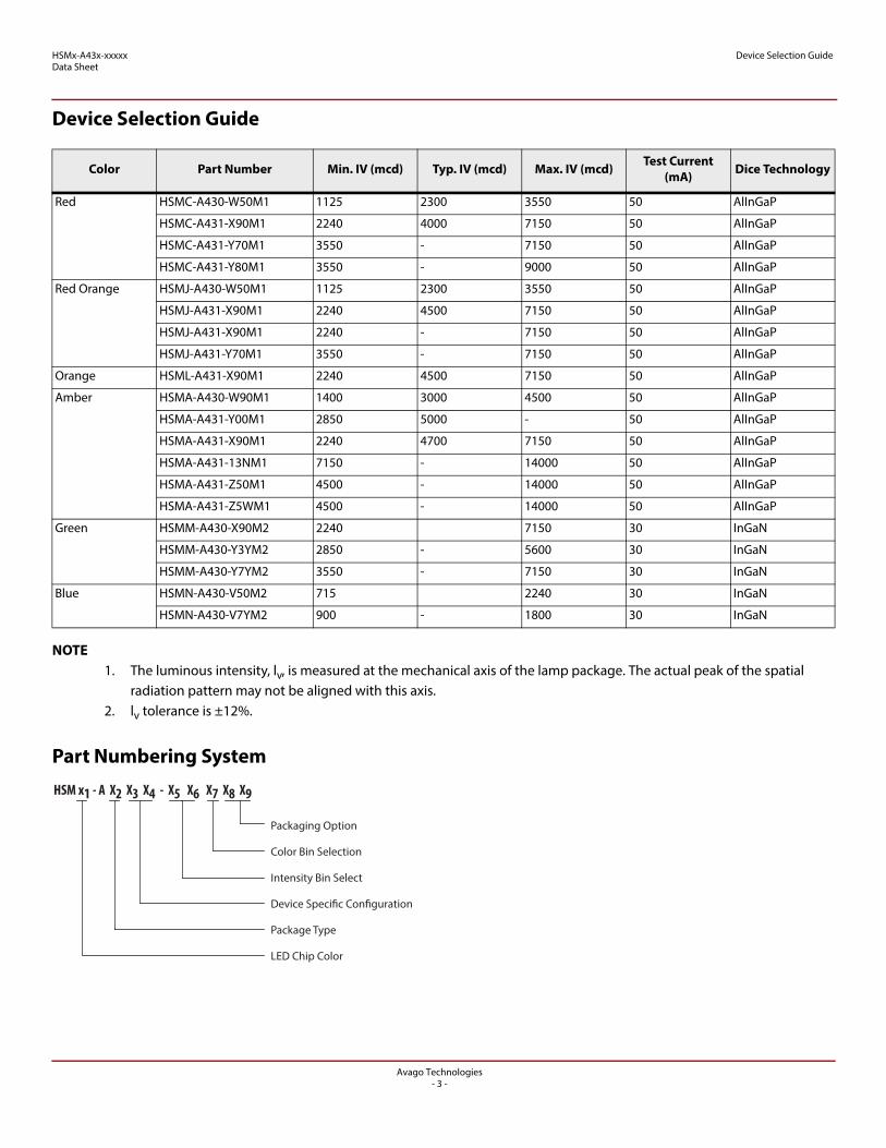
Device Selection Guide
Device Selection Guide
NOTE1. The luminous intensity, lv, is measured at the mechanical axis of the lamp package. The actual peak of the spatial
radiation pattern may not be aligned with this axis.2. lv tolerance is ±12%.
Part Numbering System
Color Part Number Min. IV (mcd) Typ. IV (mcd) Max. IV (mcd) Test Current (mA) Dice Technology
Red HSMC-A430-W50M1 1125 2300 3550 50 AlInGaP
HSMC-A431-X90M1 2240 4000 7150 50 AlInGaP
HSMC-A431-Y70M1 3550 - 7150 50 AlInGaP
HSMC-A431-Y80M1 3550 - 9000 50 AlInGaP
Red Orange HSMJ-A430-W50M1 1125 2300 3550 50 AlInGaP
HSMJ-A431-X90M1 2240 4500 7150 50 AlInGaP
HSMJ-A431-X90M1 2240 - 7150 50 AlInGaP
HSMJ-A431-Y70M1 3550 - 7150 50 AlInGaP
Orange HSML-A431-X90M1 2240 4500 7150 50 AlInGaP
Amber HSMA-A430-W90M1 1400 3000 4500 50 AlInGaP
HSMA-A431-Y00M1 2850 5000 - 50 AlInGaP
HSMA-A431-X90M1 2240 4700 7150 50 AlInGaP
HSMA-A431-13NM1 7150 - 14000 50 AlInGaP
HSMA-A431-Z50M1 4500 - 14000 50 AlInGaP
HSMA-A431-Z5WM1 4500 - 14000 50 AlInGaP
Green HSMM-A430-X90M2 2240 7150 30 InGaN
HSMM-A430-Y3YM2 2850 - 5600 30 InGaN
HSMM-A430-Y7YM2 3550 - 7150 30 InGaN
Blue HSMN-A430-V50M2 715 2240 30 InGaN
HSMN-A430-V7YM2 900 - 1800 30 InGaN
HSM x1 - A X2 X3 X4 - X5 X6 X7 X8 X9
Packaging Option
Color Bin Selection
Intensity Bin Select
Device Specific Configuration
Package Type
LED Chip Color
Avago Technologies- 3 -

HSMx-A43x-xxxxxData Sheet
Absolute Maximum Ratings (TA = 25 °C)
Absolute Maximum Ratings (TA = 25 °C)
Optical Characteristics (TA = 25 °C)
Electrical Characteristics (TA = 25 °C)
Parameters HSMC/A HSMV HSMK/M/N
DC Forward Currenta
a. Derate linearly as shown in Figure 5 and Figure 6.
70 mA 70 mA 30 mA
Peak Forward Currentb
b. Duty factor = 10%, frequency = 1kHz.
200 mA 200 mA 90 mA
Power Dissipation 180 mW 240 mW 114 mW
Reverse Voltage 5V 5V 4V
Junction Temperature 110 °C
Operating Temperature –40 °C to + 100 °C
Storage Temperature –40 °C to + 100 °C
Color Part Number Dice Technology
Peak Wavelength PEAK (nm)
Dominant Wavelength D
a (nm)
a. The dominant wavelength, D, is derived from the CIE Chromaticity Diagram and represents the color of the device.
Viewing Angle 2½
b(Degrees)
b. ½ is the off-axis angle where the luminous intensity is ½ the peak intensity.
Luminous Efficacy V
c (lm/W)
c. Radiant intensity, Ie in watts / steradian, may be calculated from the equation Ie = IV/V, where IV is the luminous intensity in candelas and V is the luminous efficacy in lumens / watt.
Typical Typical Typical Typical
Red HSMC-A43x AlInGaP 635 626 30 150
Red Orange HSMJ-A43x AlInGaP 621 615 30 240
HSMV-A430 AlInGaP 623 617 30 263
Orange HSML-A431 AlInGaP 609 605 30 320
Amber HSMA-A43x AlInGaP 592 590 30 480
Green HSMM-A430 InGaN 518 525 30 500
Blue HSMN-A43X InGaN 468 470 30 75
Cyan HSMK-A43X InGaN 500 502 30 285
Part Number
Forward Voltage VF (Volts)@IF=50 mA Reverse Voltage VR@100μA Reverse Voltage VR@10μA
Minimum Typical Maximum Minimum Minimum
HSMC/J/L/A 1.7 2.2 2.5 5 -
HSMV 1.7 2.8 3.4 5 -
Part Number
Forward Voltage VF (Volts)@IF=30 mA Reverse Voltage VR@100μA Reverse Voltage VR@10μA
Minimum Typical Maximum Minimum Minimum
HSMK/M/N 2.7 3.9 4.6 - 5
Avago Technologies- 4 -

HSMx-A43x-xxxxxData Sheet
Electrical Characteristics (TA = 25 °C)
Figure 1 Relative Intensity vs. Wavelength
0
0.2
0.4
0.6
0.8
1
380 430 480 530 580 630 680 730 780WAVELENGTH - nm
RELA
TIVE
INTE
NSIT
Y
AlInGaP Red
AlInGaP Red Orange
AlInGaP Amber
InGaNBlue
InGaNGreen
AlInGaP Orange
CyanInGaN
Figure 2 Forward Current vs. Forward Voltage
0
10
20
30
40
50
60
70
80
0 1 2 3 4 5FORWARD VOLTAGE - V
FORW
ARD
CURR
ENT -
mA HSMVHSMC/J/L/A
HSMK/M/N
Figure 3 Relative Intensity vs. Forward Current (AlInGaP) Figure 4 Relative Intensity vs. Forward Current (InGaN)
0
0.2
0.4
0.6
0.8
1.0
1.2
1.4
0 5 10 15 20 25 30 35 40 45 50 55 60 65 70 75DC FORWARD CURRENT - mA
RELA
TIVE
LUM
INOU
S INT
ENSI
TY(N
ORM
ALIZ
ED A
T 50 m
A)
0
0.2
0.4
0.6
0.8
1.0
1.2
0 5 10 15 20 25 30 35DC FORWARD CURRENT - mA
RELA
TIVE
LUM
INOU
S INT
ENSI
TY(N
ORM
ALIZ
ED A
T 30 m
A)
Avago Technologies- 5 -

HSMx-A43x-xxxxxData Sheet
Electrical Characteristics (TA = 25 °C)
Figure 5 Maximum Forward Current vs. Ambient Temperature. Drated Based on TJmax = 110 °C (AlInGaP)
Figure 6 Maximum Forward Current vs. Ambient Temperature. Drated Based on TJmax = 110 °C (InGaN)
Figure 7 Radiation Pattern
0
80
020 60 80 120
MAX
IMUM
FORW
ARD
CURR
ENT –
mA
AMBIENT TEMPERATURE – C40
40
60
30
300C/W
20
70
100
10
350C/W
470C/W
50
00
20 60 80 120
MAX
IMUM
FORW
ARD
CURR
ENT –
mA
AMBIENT TEMPERATURE – C40
20
30
15
300C/W
10
35
100
5
350C/W
470C/W
25
00.1
0.2
0.3
0.4
0.5
0.6
0.7
0.8
0.9
1
-90 -60 -30 0 30 60 90
ANGULAR DISPLACEMENT - DEGREES
NORM
ALIZ
ED IN
TENS
ITY
Avago Technologies- 6 -
HSMx-A43x-xxxxxData Sheet
Electrical Characteristics (TA = 25 °C)
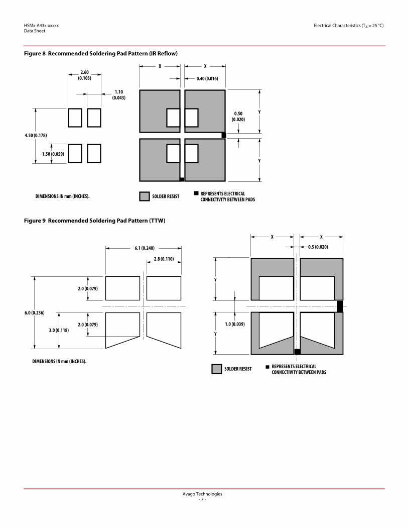
Figure 8 Recommended Soldering Pad Pattern (IR Reflow)
Figure 9 Recommended Soldering Pad Pattern (TTW)
2.60(0.103)
SOLDER RESIST REPRESENTS ELECTRICALCONNECTIVITY BETWEEN PADS
4.50 (0.178)
Y
X
0.40 (0.016)
X
0.50(0.020)
Y
1.10(0.043)
1.50 (0.059)
DIMENSIONS IN mm (INCHES).
X X
0.5 (0.020)
Y
Y
1.0 (0.039)
2.0 (0.079)
2.0 (0.079)
6.0 (0.236)
3.0 (0.118)
2.8 (0.110)
6.1 (0.240)
DIMENSIONS IN mm (INCHES).REPRESENTS ELECTRICALCONNECTIVITY BETWEEN PADS
SOLDER RESIST
Avago Technologies- 7 -

HSMx-A43x-xxxxxData Sheet
Electrical Characteristics (TA = 25 °C)
Figure 10 Soft Tip Vacuum Pick-Up Tool for Extracting SMD LED Components from Carrier Tape
Vacuum Pick-up Tool
Soft Tip
Nozzle Inner Diametersize: 1.0 to 1.5 mm
1.25mmRadius Contour
Figure 11 Recommended SnPb Reflow Soldering Profile Figure 12 Recommended Pb-Free Reflow Soldering Profile
240°C MAX.
20 SEC. MAX.
3°C/SEC.MAX.
120 SEC. MAX.
TIME
TEM
PERA
TURE
183°C100-150°C
–6°C/SEC. MAX.
60-150 SEC.
3°C/SEC. MAX.
TEM
PERA
TURE
TEM
PERA
TURE
TIME
10 to 20 SEC.
255 °C +5°C-0°C
125°C +/- 25°C
217°C
3°C/SEC MAX.
MAX. 120 SEC.
-6°C/SEC MAX.
60-150 SEC.
Figure 13 Recommended Wave Soldering Profile
LAMINAR WAVE BOTTOM SIDEOF PC BOARDHOT AIR KNIFE
TURBULENT WAVE
FLUXING
PREHEAT
0 10 20
3050
100
150
200
250
30 40 50TIME – SECONDS
TEM
PERA
TURE
– C
60 70 80 90 100
TOP SIDE OFPC BOARD
CONVEYOR SPEED = 1.83 M/MIN (6 FT/MIN)PREHEAT SETTING = 150 C (100 C PCB)SOLDER WAVE TEMPERATURE = 245 CAIR KNIFE AIR TEMPERATURE = 390 CAIR KNIFE DISTANCE = 1.91 mm (0.25 IN.)AIR KNIFE ANGLE = 40 SOLDER: SN63; FLUX: RMA
NOTE: ALLOW FOR BOARDS TO BE SUFFICIENTLYCOOLED BEFORE EXERTING MECHANICAL FORCE.
Avago Technologies- 8 -
HSMx-A43x-xxxxxData Sheet
Electrical Characteristics (TA = 25 °C)
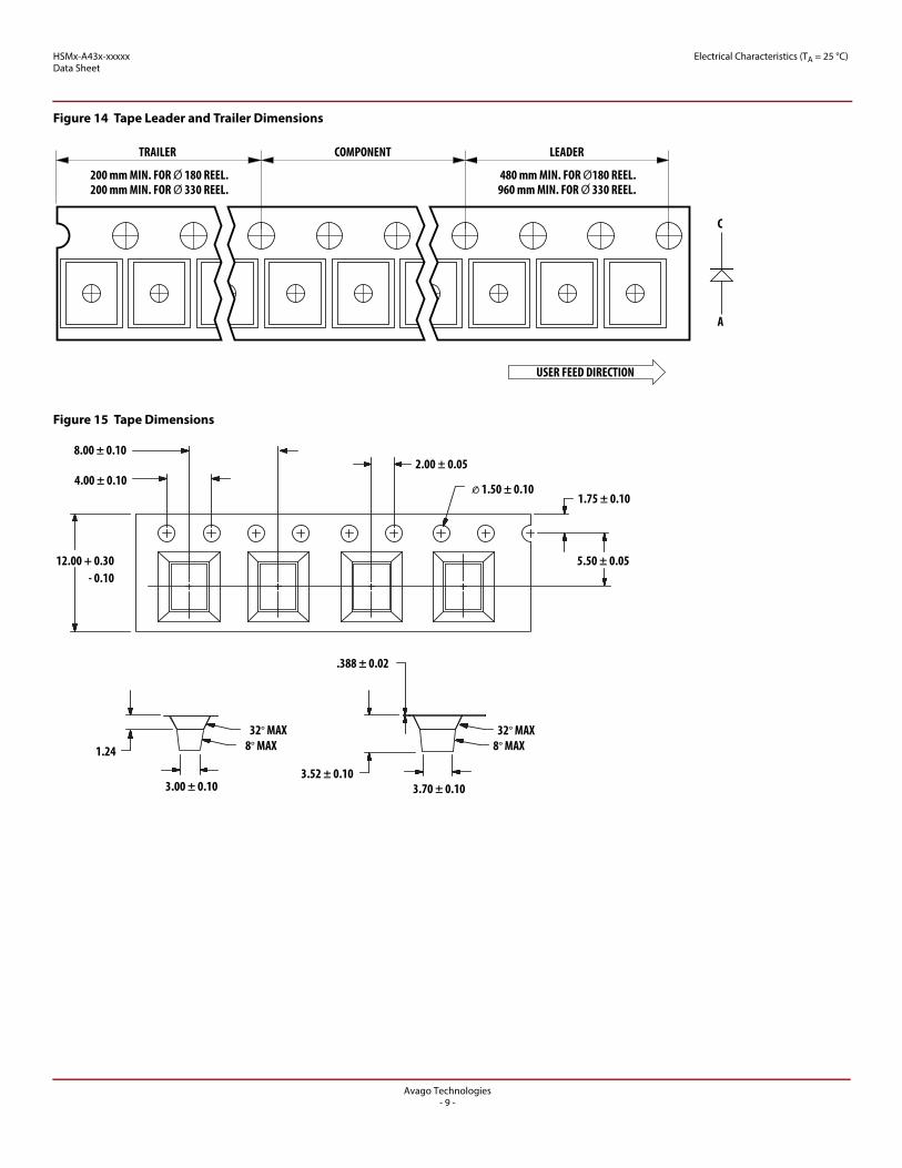
Figure 14 Tape Leader and Trailer Dimensions
Figure 15 Tape Dimensions
200 mm MIN. FOR O 180 REEL.200 mm MIN. FOR O 330 REEL.
TRAILER COMPONENT LEADER
480 mm MIN. FOR O180 REEL.960 mm MIN. FOR O 330 REEL.
C
A
USER FEED DIRECTION
2.00 ± 0.05
1.75 ± 0.10
5.50 ± 0.05
.388 ± 0.02
3.52 ± 0.103.70 ± 0.103.00 ± 0.10
8° MAX
12.00 + 0.30- 0.10
8.00 ± 0.10
4.00 ± 0.10
1.24
32° MAX8° MAX
32° MAX
O 1.50 ± 0.10
Avago Technologies- 9 -

HSMx-A43x-xxxxxData Sheet
Moisture Sensitivity
Figure 16 Reeling Orientation
Moisture SensitivityThis product is qualified as Moisture Sensitive Level 2a per JEDEC J-STD-020. The following precautions for handling this moisture-sensitive product will help to ensure the reliability of the product. Refer to Avago Application Note AN5305, Handling of Moisture Sensitive Surface Mount Devices, for details.
A. Storage before use
An unopened moisture barrier bag (MBB) can be stored at < 40 °C / 90% RH for 12 months. If the actual shelf life has exceeded 12 months and the humidity indicator card (HIC) indicates that baking is not required, then it is safe to reflow the LEDs per the original MSL rating.
Do not open the MBB prior to assembly (e.g., for IQC).
B. Control after opening the MBB
Read the humidity indicator card (HIC) immediately upon opening the MBB.
Keep the LEDs at < 30 °C / 60% RH at all times. Complete all high-temperature-related processes, including soldering, curing, or rework, within 672 hours.
C. Control for unfinished reel
Store any unused LEDs in a sealed MBB with desiccant or desiccator at <5% RH.
D. Control of assembled boards
If the PCB that is soldered with the LEDs is to be subjected to other high-temperature processes, store the PCB in a sealed MBB with desiccant or desiccator at <5% RH to ensure that the LEDs have exceeded their floor life of 672 hours.
E. Baking is required if:
“10%” is not blue and “5%” HIC indicator turns pink. The LEDs are exposed to conditions of >30 °C / 60% RH at
any time. The LEDs’ floor life has exceeded 672 hours.
Recommended baking condition: 60 °C ± 5 °C for 20 hours.
CATHODE SIDE
USER FEED DIRECTION
PRINTED LABEL
Avago Technologies- 10 -

HSMx-A43x-xxxxxData Sheet
Intensity Bin Select (X5X6)
Intensity Bin Select (X5X6)
The individual reel contains parts from one half bin only.
Intensity Bin Limits
Tolerance of each bin limit = ± 12%.
X5 Min Iv Bin
X6
0 Full Distribution
2 2 half bins starting from X51
3 3 half bins starting from X51
4 4 half bins starting from X51
5 5 half bins starting from X51
6 2 half bins starting from X52
7 3 half bins starting from X52
8 4 half bins starting from X52
9 5 half bins starting from X52
Bin ID Min (mcd) Max (mcd)
U1 450.00 560.00
U2 560.00 715.00
V1 715.00 900.00
V2 900.00 1125.00
W1 1125.00 1400.00
W2 1400.00 1800.00
X1 1800.00 2240.00
X2 2240.00 2850.00
Y1 2850.00 3550.00
Y2 3550.00 4500.00
Z1 4500.00 5600.00
Z2 5600.00 7150.00
11 7150.00 9000.00
12 9000.00 11250.00
21 11250.00 14000.00
22 14000.00 18000.00
Avago Technologies- 11 -

HSMx-A43x-xxxxxData Sheet
Color Bin Select (X7)
Color Bin Select (X7)
The individual reel contains parts from one full bin only.
Color Bin Limits
Packaging Option (X8X9)
Forward Voltage Bin TAbleFor HSMV-A43x-xxxxx only.
Tolerance for each bin limit = ± 0.1V.
X7
0 Full Distribution
Z A and B only
Y B and C only
W C and D only
V D and E only
U E and F only
T F and G only
S G and H only
Q A, B and C only
P B, C and D only
N C, D and E only
M D, E and F only
L E, F and G only
K F, G and H only
1 A, B, C and D only
2 E, F G and H only
Blue Min. (nm) Max. (nm)
A 460.0 465.0
B 465.0 470.0
C 470.0 475.0
D 475.0 480.0
Cyan Min. (nm) Max. (nm)
A 490.0 495.0
B 495.0 500.0
C 500.0 505.0
D 505.0 510.0
Green Min. (nm) Max. (nm)
A 515.0 520.0
B 520.0 525.0
C 525.0 530.0
D 530.0 535.0
Amber Min. (nm) Max. (nm)
A 582.0 584.5
B 584.5 587.0
C 587.0 589.5
D 589.5 592.0
E 592.0 594.5
F 594.5 597.0
Orange Min. (nm) Max. (nm)
A 597.0 600.0
B 600.0 603.0
C 603.0 606.0
D 606.0 609.0
E 609.0 612.0
Red/ Orange Min. (nm) Max. (nm)
A 611.0 616.0
B 616.0 620.0
Red Min. (nm) Max. (nm)
Full Distribution
Option Test Current Package Type Reel Size
M1 50mA Top Mount 13 inch
M2 30mA Top Mount 13 inch
Bin Min. Max.
VA 1.9 2.2
VB 2.2 2.5
VC 2.5 2.8
VD 2.8 3.1
VE 3.1 3.4
Avago Technologies- 12 -

For product information and a complete list of distributors, please go to our web site: www.avagotech.com
Avago Technologies and the A logo are trademarks of Avago Technologies in the United States and other countries. All other brand and product names may be trademarks of their respective companies.
Data subject to change. Copyright © 2015–2016 Avago Technologies. All Rights Reserved.
AV02-0208EN – April 21, 2016