HS-21/HS-41X Handheld Reader User Manual -...
177
HS-21/HS-41X Handheld Reader User Manual P/N 84-100052 Rev B
Transcript of HS-21/HS-41X Handheld Reader User Manual -...

P/N 84-100052 Rev B

Copyright and Disclaimer
Copyright ©2015Microscan Systems, Inc.Tel: +1.425.226.5700 / 800.762.1149 Fax: +1.425.226.8250
All rights reserved. The information contained herein is proprietary and is provided solely for the purpose of allowing customers to operate and/or service Microscan manufactured equipment and is not to be released, reproduced, or used for any other purpose without written permission of Microscan.
Throughout this manual, trademarked names might be used. We state herein that we are using the names to the benefit of the trademark owner, with no intention of infringement.
DisclaimerThe information and specifications described in this manual are subject to change without notice.
Latest Manual VersionFor the latest version of this manual, see the Download Center on our web site at: www.microscan.com.
Technical SupportFor technical support, e-mail: [email protected].
WarrantyFor current warranty information, see: www.microscan.com/warranty.
Microscan Systems, Inc.
United States Corporate Headquarters+1.425.226.5700 / 800.762.1149
United States Northeast Technology Center+1.603.598.8400 / 800.468.9503
European Headquarters+31.172.423360
Asia Pacific Headquarters+65.6846.1214
ii HS-21/HS-41X Handheld Reader User Manual

Introduction
-2-3-4-5-6-7-90
-2-3-4-55
-2-3-4-6
-2-3-4-5-7-8-901345
-2-3-4-5-6-7-8-90
-2-3-4-5
Table of Contents
Chapter 1 Quick Start Check Required Hardware ...................................................................... 1USB Interface .......................................................................................... 1RS-232 Interface ..................................................................................... 1Install ESP ............................................................................................... 1Select Model ............................................................................................ 1Select Interface and Connect to Reader ................................................. 1Configure the Reader .............................................................................. 1Save Changes in ESP ........................................................................... 1-1
Chapter 2 Using ESPEZ Mode .................................................................................................. 2Application Mode ..................................................................................... 2Tree Controls ........................................................................................... 2Menu Toolbar .......................................................................................... 2Send/Receive ....................................................................................... 2-1
Chapter 3 Basic OperationsPractice Targeting ................................................................................... 3Motion Detect Mode ................................................................................ 3Dual Optics .............................................................................................. 3Operational Feedback ............................................................................. 3
Chapter 4 CommunicationsCommunications by ESP......................................................................... 4Communications Overview...................................................................... 4USB Interface .......................................................................................... 4RS-232 Interface ..................................................................................... 4Preamble ................................................................................................. 4Postamble................................................................................................ 4Preamble and Postamble by ESP ........................................................... 4Keyboard Mapping ................................................................................ 4-1Communications Mode.......................................................................... 4-1USB Keyboard Rate .............................................................................. 4-1RS-232 .................................................................................................. 4-1Text Command Timeout ........................................................................ 4-1
Chapter 5 Read CycleRead Cycle by ESP ................................................................................. 5External Trigger ....................................................................................... 5Default Continuous Event........................................................................ 5Maximum Decodes per Read .................................................................. 5Read Cycle Timeout ................................................................................ 5Ignore Duplicate Symbol Timeout ........................................................... 5Targeting Zone Tolerance ....................................................................... 5Morphological Preprocessing .................................................................. 5Camera Settings.................................................................................... 5-1
Chapter 6 SymbologiesSymbologies by ESP ............................................................................... 6Data Matrix .............................................................................................. 6QR Code.................................................................................................. 6Aztec........................................................................................................ 6
HS-21/HS-41X Handheld Reader User Manual iii

iv
Table of Contents
HS-21/HS-41X Handheld Reader User Manual
Code 39................................................................................................... 6-6Code 128................................................................................................. 6-7BC412 ..................................................................................................... 6-8Code 93................................................................................................... 6-9Codabar................................................................................................. 6-10Interleaved 2 of 5................................................................................... 6-11UPC....................................................................................................... 6-12Postal .................................................................................................... 6-13Pharmacode .......................................................................................... 6-14GS1 DataBar ......................................................................................... 6-16PDF417 ................................................................................................. 6-17MicroPDF417 ........................................................................................ 6-18Composite ............................................................................................. 6-19Symbology Identifier .............................................................................. 6-20
Chapter 7 I/O ParametersI/O Parameters by ESP ........................................................................... 7-2No Read Notification ............................................................................... 7-3Targeting ................................................................................................. 7-4Beeper..................................................................................................... 7-5Vibrate ..................................................................................................... 7-6Button Stay-Down Time .......................................................................... 7-7Motion Detect Event ................................................................................ 7-8Image Quality .......................................................................................... 7-9Data Validation ...................................................................................... 7-10
Chapter 8 Advanced OperationsContinuous Read..................................................................................... 8-2Mirroring .................................................................................................. 8-3Motion Detection ..................................................................................... 8-4Window of Interest................................................................................... 8-5
Chapter 9 TerminalTerminal View.......................................................................................... 9-2Find ......................................................................................................... 9-3Send ........................................................................................................ 9-4Macros..................................................................................................... 9-5Terminal Right-Click Menu ...................................................................... 9-6Terminal Dropdown Menu ....................................................................... 9-7
Chapter 10 UtilitiesDevice Control ....................................................................................... 10-2Differences from Default........................................................................ 10-3Firmware ............................................................................................... 10-4Advanced .............................................................................................. 10-6
AppendicesAppendix A General Specifications .........................................................A-2Appendix B Electrical Specifications .......................................................A-5Appendix C Configuration Symbols.........................................................A-6Appendix D Serial Commands ..............................................................A-17Appendix E Communications Protocol ..................................................A-48Appendix F ASCII Table........................................................................A-49Appendix G Maintenance ......................................................................A-50Appendix H Glossary of Terms .............................................................A-51
About the HS-21 and HS-41X Handheld Readers
About the HS-21 and HS-41X Handheld ReadersThe HS-21 is a general-purpose 2D reader. Its many features include dual field optics for both high density and wide angle performance, a ruggedized design, IP54 sealing against dust and water, and compact size.
The HS-41X is a special-purpose 2D reader for decoding direct part marks (DPM). Microscan’s X-Mode decode algorithms make the HS-41X an ideal solution for reading difficult marks on many surfaces, including PCBs, electrical components, castings, and sheet metal. Its tough design makes it a good choice for manufacturing and light industrial applications.
Both readers can be configured and tested easily using the intuitive tree controls and user interface of Microscan’s ESP Software.
Note: The HS-21 and HS-41X have unique algorithm licenses, and the HS-21 cannot be field-upgraded to an HS-41X.
About This ManualThis manual provides complete information on setting up, installing, and configuring the HS-21 and HS-41X. The chapters are presented in the order in which the reader would be assembled, configured, and optimized.
HighlightingCross-references and web addresses are highlighted in blue bold.
References to ESP, its toolbar headings, and menu headings are highlighted in Bold Initial Caps.

Introduction
Statement of Agency Compliance
The HS-21 and HS-41X have been tested for compliance with FCC regulations and were found to be compliant with all applicable FCC Rules and Regulations.
IMPORTANT NOTE: To comply with FCC RF exposure compliance requirements, this device must not be co-located or operate in conjunction with any other antenna or transmitter.
CAUTION: Changes or modifications not expressly approved by the party responsible for compliance could void the user's authority to operate the equipment.
The HS-21 and HS-41X have been tested for compliance to CE (Conformité Européenne) standards and guidelines and were found to conform to applicable CE standards, specifically the EMC requirements EN 55024, ESD EN 61000-4-2, Radiated RF Immunity EN 61000-4-3, ENV 50204, EFT EN 61000-4-4, Conducted RF Immunity EN 61000-4-6, EN 55022, Class B Radiated Emissions, and Class B Conducted Emissions.

t uct cts f
cts.
nd
our
te of
ct. ll as
nt
tion
Statement of RoHS ComplianceAll Microscan readers with a ‘G’ suffix in the FIS number are RoHS-Compliant. All complianreaders were converted prior to March 1, 2007. All standard accessories in the Microscan ProdPricing Catalog are RoHS-Compliant except 20-500013-01 and 98-000039-02. These produmeet all the requirements of “Directive 2002/95/EC” European Parliament and the Council othe European Union for RoHS compliance. In accordance with the latest requirements, our RoHS-Compliant products and packaging do not contain intentionally added Deca-BDE,Perfluorooctanes (PFOS) or Perfluorooctanic Acid (PFOA) compounds above the maximumtrace levels. To view the document stating these requirements, please visit:
http://eur-lex.europa.eu/LexUriServ/LexUriServ.do?uri=CELEX:32002L0095:EN:HTML
and
http://eur-lex.europa.eu/LexUriServ/LexUriServ.do?uri=OJ:L:2006:372:0032:0034:EN:PDF
Please contact your sales manager for a complete list of Microscan’s RoHS-Compliant produ
This declaration is based upon information obtained from sources which Microscan believes to be reliable, afrom random sample testing; however, the information is provided without any representation of warranty, expressed or implied, regarding accuracy or correctness. Microscan does not specifically run any analysis onraw materials or end product to measure for these substances. The information provided in this certification notice is correct to the best of Microscan’s knowledge at the dapublication. This notice is not to be considered a warranty or quality specification. Users are responsible for determining the applicability of any RoHS legislation or regulations based on their individual use of the produIn regards to “RoHS Directive 2011_65_EU” Microscan produces Monitoring and Control Instruments as weIndustrial Monitoring & Control Instruments as defined within the directive. Microscan has developed and is implementing a RoHS2 compliance plan with the intention of bringing all active products listed in our curremarketing literature within full compliance as per the directive deadlines. Key milestones for the transition plan are as follows:• Complete internal product audit by July 2014.• Initial “Monitoring and Control Instruments” RoHS2 compliant products available by December 2014• Initial “Industrial Monitoring & Control Instruments” RoHS2 compliant products available by July 2015• All new products introduced in 2015 are expected to be WEEE & RoHS2 compliant.Microscan will mark the products with the ‘CE’ marking that complies with the RoHS2 process to acquire ‘CE’ certificaper the example given: Example >> Machinery directive + EMC directive + RoHS2 = Declaration of Conformity.

1 Quick StartContents
This section is designed to get your HS-21 or HS-41X Handheld Reader up and running quickly using Microscan’s ESP Software so you can get a sense of its capabilities and test sample symbols. Detailed setup information for configuring the reader for your specific application can be obtained in the subsequent sections.
Your interface type will determine how data is received by the host. When sending data by USB, you must open a text editor in your host computer. When sending data by RS-232, you must use a terminal program such as ESP’s Terminal view.
Check Required Hardware ........................................................................................................... 1-2USB Interface ............................................................................................................................... 1-3RS-232 Interface .......................................................................................................................... 1-4Install ESP.................................................................................................................................... 1-5Select Model................................................................................................................................. 1-6Select Interface and Connect to Reader ...................................................................................... 1-7Configure the Reader ................................................................................................................... 1-9Save Changes in ESP................................................................................................................ 1-10
HS-21/HS-41X Handheld Reader User Manual 1-1

Check Required Hardware
1-2 HS-21/HS-41X Handheld Reader User Manual
Check Required HardwareThe HS-21/HS-41X is shipped with one of the following cables:
USB Hardware• HS-21/HS-41X Handheld Reader
• USB Cable
RS-232 Hardware• HS-21/HS-41X Handheld Reader
• RS-232 Cable
• RS-232 Power Supply
Changing Cable and Communications InterfaceThe reader can be converted from USB to RS-232 or from RS-232 to USB by changing the cable and scanning the appropriate communications programming symbol below. To detach the USB or RS-232 cable from the reader, press a paper clip into the hole on the side of the handle and gently pull the cable out of the connector.
6’ USB Straight Cable 8’ RS-232 Coiled Cable
USB Interface RS-232 InterfaceSave Settings

Quick Start
HS-21/HS-41X Handheld Reader User Manual 1-3
USB InterfaceNote: The USB interface draws its power from the host computer.
USB Configuration
Installation Steps for USBTo power on the reader, plug the USB cable into the reader’s handle and into the host’s USB port. After several seconds, the reader will beep twice and the LED will turn off. The reader will now be ready to use.
Important: If you use a USB hub, be sure that it is a powered hub.
Read the Save Settings symbol.
Item Description Part Number
1HS-21 Handheld Reader FIS-HS21-000XG
HS-41X Handheld Reader FIS-HS41X-000XG
2USB Cable, 6’ Straight 61-000224-01
USB Cable, 8’ Coiled 61-000224-02
USB Configuration
1
2
Default to USB (HID)
Save Settings
Test Symbol(ABCDEFGHIJKLMNOP)

RS-232 Interface
1-4 HS-21/HS-41X Handheld Reader User Manual
RS-232 InterfaceNote: Unlike USB, the RS-232 interface does not draw its power from the host computer, and requires a power supply.
RS-232 Configuration
Installation Steps for RS-232To power on the reader, plug the RS-232 cable into the reader’s handle, plug the power supply into the AC outlet, plug the power supply cord into the barrel jack on the cable, and then connect the cable to the appropriate serial port on the host. After several seconds, the unit will beep twice and the LED will turn off. The reader will now be ready to use.
Read the Save Settings symbol.
Item Description Part Number
1HS-21 Handheld Reader FIS-HS21-000XG
HS-41X Handheld Reader FIS-HS41X-000XG
2 RS-232 Cable, 8’ Coiled 61-000224-03
3
RS-232 Power Supply, U.S. 20-000335-02
RS-232 Power Supply, Euro 20-000336-02
RS-232 Power Supply, UK 20-000337-02
3
RS-232 Configuration
1
2
Reset to RS-232 Factory Defaults
Test Symbol(ABCDEFGHIJKLMNOP)
Save Settings

Quick Start
Install ESPESP Software is Microscan’s configuration and testing software. Use ESP to set up your HS-21 or HS-41X Handheld Reader.
ESP can be found on the Microscan Tools Drive that is packaged with the reader.
1. Follow the prompts to install ESP from the Tools Drive.
2. Click on the ESP icon to run the program.
Note: ESP can also be installed from the Download Center at www.microscan.com.
Minimum System Requirements• 233 MHz Pentium PC
• Windows 8, 7, Vista, or XP operating system (32-bit or 64-bit)
• Internet Explorer 6.0 or higher
• 128 MB RAM or greater
• 160 MB free disk space
• 800 x 600 256 color display (1024 x 768 32-bit color recommended)
HS-21/HS-41X Handheld Reader User Manual 1-5

Select Model
1-6 HS-21/HS-41X Handheld Reader User Manual
Select ModelWhen you start ESP, the following menu will appear:
1. Click the HS-21/HS-41X button and then click OK. If you do not want to make thisselection every time you start ESP, uncheck “Show this dialog at startup”. If you needto select another model later, click Switch Model at the top of the screen.
Note: You can also type a name of your choice in the Description text field and click OK.
2. Click Yes when this dialog appears:

Quick Start
HS-21/HS-41X Handheld Reader User Manual 1-7
Select Interface and Connect to Reader
USB• In the communications dialog box, select the communications interface you are using
and click Next.
• Click the Show Connect Symbol button, print the USB Connect Mode symbol, anddecode it with the reader to ensure that you are in the correct communications interface.Keep the printed symbol in a convenient place for future use.
• Click Next when you are finished.
The Select Device dialog will then reappear:
• You will see a “ Reader” ID number in the Select Device field. Click Connect.
• When you are connected successfully, the CONNECTED message will appear in agreen box in the status bar at the bottom right of the screen.
You are now ready to configure your reader using ESP. Subsequent sections provide more detailed information about ESP’s configuration options.
Click the Show Connect Symbol button.
Reader ID number should match the serial number next to the trigger under the optical head of the reader.

Select Interface and Connect to Reader
RS-232• In the Select Protocol dialog box, select the communications interface you are using
and click Next.
• Print the RS-232 Connect Mode symbol (also shown in the Install ESP step) anddecode it with the reader to ensure that you are in the correct communications interface.Keep the printed symbol in a convenient place for future use.
• Click Next when you are finished.
• The Com Port dialog will then reappear. Select which communications port you areusing. If you don’t see your communications port listed on the dropdown menu, select Other.
• Click Connect.
• When you are connected successfully, the CONNECTED message will appear in agreen box in the status bar at the bottom right of the screen.
If the connection attempt fails, enable a different communications port, check your port connections, and try again.
You are now ready to configure your reader using ESP. Subsequent sections provide more detailed information about ESP’s configuration options.
Click the Show Connect Symbol button.
1-8 HS-21/HS-41X Handheld Reader User Manual

Quick Start
Configure the ReaderClick the App Mode button to make configuration changes.
The following modes are accessible by clicking the buttons in the first row of App Mode icons:
• Click the EZ Mode button to return to the EZ Mode view.
• Click the Autoconnect button to establish communication.
• Click the Send/Recv button to send or receive commands.
• Click the Switch Model button to open the model menu, or to return to a previous model.
• Click the Parameters button to show the tabbed tree controls for Communication, ReadCycle, Symbologies, and I/O Parameters.
• Click the Imager button to capture and decode symbols and to use Window of Interestfor Near Field and Far Field.
• Click the Terminal button to display decoded symbol data and to send serial commandsto the reader using text or macros.
• Click the Utilities button to show the tabbed interfaces for Device Control, Differencesfrom Default, Firmware, and Advanced settings.
For further details, see ESP Help in the dropdown Help menu.
HS-21/HS-41X Handheld Reader User Manual 1-9

Save Changes in ESP
Save Changes in ESPTo make changes to a configuration setting:
Saving Options• Send, No Save. Changes will be lost when power is re-applied to the reader.
• Send and Save. This activates all changes in current memory and saves to the readerfor power-on.
1. Left-click on the +to expand thedesired tree.
2. Double-click on thedesired parameterand click once in theselection box to viewoptions.
5. Right-click on the openscreen and select Save toReader to implement thecommand in the reader.
4. Left-click again on theopen screen to completeyour selection.
3. Place your cursor in theselection box, scroll down to the setting you want tochange, and click once onthe setting.
1-10 HS-21/HS-41X Handheld Reader User Manual
2 Using ESPContents
This section is designed to help you understand the structure and application of ESP.
When you open ESP, unless otherwise specified in the ESP Preferences dialog accessible from the Options heading on the menu toolbar, you will enter EZ Mode for initial setup. From there, you can enter Application Mode (App Mode) and access several configuration menus (Communications, Read Cycle, Symbologies, I/O Parameters, an Imager interface, a Terminal interface, and a Utilities interface).
ESP can be used to configure the HS-21 and HS-41X Handheld Readers in the following ways:
• Tree Controls: Each configuration menu contains a list of all option settings that pertainto that specific element of reader operation. For example, the Communications menushows a Communications Mode command, and then the options RS-232 Serial, USBKeyboard, and USB Native (HID), all of which are accessible from a dropdown menu.
• Graphic User Interfaces: Settings can be configured using such point-and-click toolsas radio buttons, tabs, spin boxes, check boxes, and drag-and-drop functions.
• Terminal: ESP’s Terminal interface allows you to send configuration and utility commandsdirectly to the reader by typing them in the provided text field.
EZ Mode....................................................................................................................................... 2-2Application Mode.......................................................................................................................... 2-3Tree Controls................................................................................................................................ 2-4Menu Toolbar ............................................................................................................................... 2-5Send/Receive ............................................................................................................................ 2-15
HS-21/HS-41X Handheld Reader User Manual 2-1

EZ Mode
2-2 HS-21/HS-41X Handheld Reader User Manual
EZ ModeEZ Mode offers instructions on positioning the reader in relation to a test symbol and triggering the reader to decode the symbol.
Enter App Mode to access configuration trees and other setup features.
Click Start to find the test symbol within the field of view and to to take an image capture of the symbol. Trigger the reader manually or check Auto Trigger for ESP to trigger the reader and decode the symbol data. Decoded symbol data will appear in the field beneath the viewing area. Click Stop to end the locate and trigger functions.
Hint: Right-click on the image to save it to your PC.

Using ESP
Application ModeFrom EZ Mode, you can click on the App Mode button to access specific configuration menus, Utilities tools, and a Terminal window where serial commands can be entered.
Note: The App Mode and EZ Mode buttons appear in the same position to allow easy switching between these primary modes.
Note: See the corresponding sections of this documentation for specific information on any of the views or modes mentioned above.
Menu toolbar.Click this icon to return to EZ Mode.
Click the Parameters icon to return to full App Mode view from Terminal or Utilities.
Click on tabs in this row to access configuration trees like the one shown below.
Click here to open the Imager, Terminal, or Utilities views.
HS-21/HS-41X Handheld Reader User Manual 2-3
Tree Controls
2-4 HS-21/HS-41X Handheld Reader User Manual
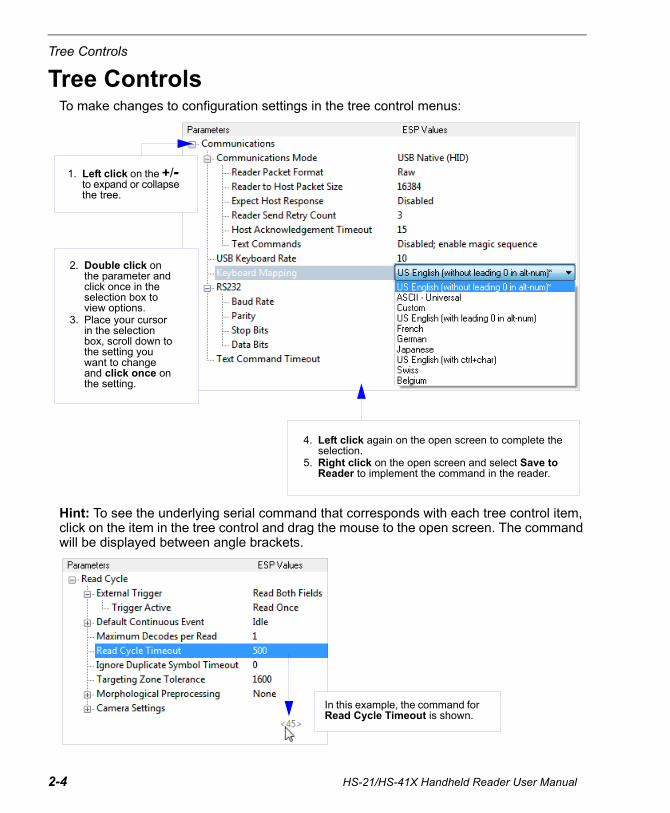
Tree ControlsTo make changes to configuration settings in the tree control menus:
Hint: To see the underlying serial command that corresponds with each tree control item, click on the item in the tree control and drag the mouse to the open screen. The command will be displayed between angle brackets.
2. Double click onthe parameter andclick once in theselection box toview options.
3. Place your cursorin the selectionbox, scroll down tothe setting youwant to changeand click once onthe setting.
4. Left click again on the open screen to complete theselection.
5. Right click on the open screen and select Save toReader to implement the command in the reader.
1. Left click on the +/-to expand or collapsethe tree.
In this example, the command for Read Cycle Timeout is shown.

Using ESP
Menu Toolbar
File > NewWhenever New is selected from the File menu, the default configuration of ESP is loaded.
Open / SaveWhen Save or Save As is selected, the ESP configuration is saved to the host computer’s hard drive and available whenever the same file is selected under Open.
When you save menu changes to your hard drive, these changes are not saved to your reader. The diagram below shows how settings can be saved and received between ESP and the reader, and ESP and the host hard drive.
Import / ExportImport converts the ASCII settings from a text file to ESP configuration settings.
Export converts the active ESP configuration settings to an ASCII text file.
(Save to Reader)
(Receive Reader Settings)
HS-21/HS-41X Handheld Reader User Manual 2-5

Menu Toolbar
ModelThe Model menu allows you to select between reader models. When you choose another model, the current connection with your present model will be terminated.
New ModelTo connect to another model, select New Model, choose the model you want, and click OK.
All models you have selected and enabled will continue to appear in the dropdown model menu. The New Model option is repeated when you click the Switch Model button on the top row of icons.
2-6 HS-21/HS-41X Handheld Reader User Manual

Using ESP
HS-21/HS-41X Handheld Reader User Manual 2-7
OptionsYou can use the Options menu to save memos and set up ESP preferences.
Preferences will be saved and loaded into ESP the next time ESP is opened, whether or not you save the ESP file to the host computer.
Preferences > General Tab
Reload Last FileAt startup, reloads the last file saved to the computer.
Show Model PromptAt startup, remembers the last connected model and displays it in the Connecting... dialog whenever you attempt to connect.
Show Connect Prompt At startup, displays the Would you like to connect... prompt.
Receive After ConnectAt startup, loads the reader’s settings into ESP. (This is not recommended if you want to preserve your ESP settings for future use.)
Skip EZ ModeAt startup, skips EZ Mode and opens directly in App Mode.
The Toolbar Style options allow you to determine how ESP will display the mode options in the two rows at the top of the screen.

Menu Toolbar
2-8 HS-21/HS-41X Handheld Reader User Manual
Preferences > Terminal Tab
Show Non-Printable Characters When Show Non-Printable Characters is enabled, characters such as “CRLF” will be displayed in the Terminal window. When Enhanced Format is checked, the characters are displayed with more detailed formatting.
Change Keyboard MacrosClicking the Change Keyboard Macros button brings up the Function Keys dialog. In this dialog you can select the desired function key and then enter your macro keystrokes in the associated key map. For example, to make Ctrl-F2 the keystroke to send a trigger character, select F2, then in the Ctrl row, enter <trigger character> and click OK. Then whenever the Ctrl-F2 keystroke is pressed, the trigger character will start the read cycle.
Note: The F1 key is reserved for opening ESP Help and the F3 key is reserved for the Find Next function.
Change FontAllows you to modify the font used for decode data received from the reader on the Terminal screen.
Change Echo FontAllows you to modify the font used for command characters typed into the Terminal view.
Enable EchoAllows you to enter command characters in Terminal.
Display Incoming Data Even When Not in FocusWhen Display Incoming Data Even When Not in Focus is enabled, data from the reader will continue to appear in the Terminal even when ESP is not the top window.

Using ESP
Preferences > Bar Code Options Tab
The Bar Code Options dialog allows you to set the size of user-created symbols.
Sizing InformationSets the bar width or module width (in mils, or thousandths of an inch) of user-created symbols.
Example: A bar width of 14 is 0.014 inches.
HS-21/HS-41X Handheld Reader User Manual 2-9

Menu Toolbar
Preferences > Advanced Tab
The Auto Sync options at the top of the Advanced tab allow the user to determine whether Auto Sync will be enabled automatically in sections of ESP where it is used, or if it will ask before it enables Auto Sync functions.
Always Ask Before Auto Sync OccursIf this option box is checked, specific Auto Sync functions can be enabled. Receive Settings from the Reader will automatically send the reader’s settings to ESP when Auto Sync is enabled. Send ESP Settings to the Reader will automatically send all reader configuration settings chosen in ESP to the reader. Do Not Send or Receive Settings creates a condition in which Auto Sync will not automatically send reader settings to ESP, or send ESP settings to the reader.
Include Preamble and Postamble with Send SaveWhen this option box is checked, the user-configured Preamble and Postamble characters will be sent along with other parameters.
Send XON with AutoconnectSends an XON (Begin Transmission) command to the reader before starting the Autoconnect routine.
2-10 HS-21/HS-41X Handheld Reader User Manual

Using ESP
Ask to Save ESP File when QuittingWhen enabled, prompts the user to save a .esp file when ending a session.
The .esp file will be saved in the location of your choice.
Use Default Storage LocationWhen enabled, automatically stores data in ESP’s Application Data folder.
HS-21/HS-41X Handheld Reader User Manual 2-11

Menu Toolbar
Document MemoThe information you type in the Document Memo field will appear in a context-sensitive text box whenever your cursor hovers over the Document Memo item on the Options menu.
Model MemoSimilar to Document Memo, the information you type in the Model Memo field will appear in a context-sensitive text box whenever your cursor hovers over the Model Memo item on the Options menu. Memos created in Model Memo are specific to the model enabled when the message was created.
Note: Memos must be saved in a .esp file if you want them to available in your next session. If you do not save your current session, any memos that you have entered during the session will be discarded, and will be unavailable in your next session.
2-12 HS-21/HS-41X Handheld Reader User Manual
Using ESP
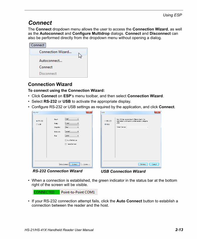
ConnectThe Connect dropdown menu allows the user to access the Connection Wizard, as well as the Autoconnect and Configure Multidrop dialogs. Connect and Disconnect can also be performed directly from the dropdown menu without opening a dialog.
Connection WizardTo connect using the Connection Wizard:
• Click Connect on ESP’s menu toolbar, and then select Connection Wizard.
• Select RS-232 or USB to activate the appropriate display.
• Configure RS-232 or USB settings as required by the application, and click Connect.
• When a connection is established, the green indicator in the status bar at the bottomright of the screen will be visible.
• If your RS-232 connection attempt fails, click the Auto Connect button to establish aconnection between the reader and the host.
RS-232 Connection Wizard USB Connection Wizard
HS-21/HS-41X Handheld Reader User Manual 2-13

Menu Toolbar
ViewThe View menu allows the user to move quickly between the Parameters, Imager, Terminal, and Utilities interfaces without using the icon buttons on the App Mode toolbar. It also allows the user to access the Bar Code Dialog, shown below.
Bar Code DialogSymbols can be created in the Bar Code Dialog by typing the text to be encoded. This is a useful tool for creating configuration symbols, allowing the user to configure the reader by reading the user-created symbols.
Drag specific configuration values from the control tree directly into this field to encode new symbols.
Choose a spatial orientation for the new symbol.
Create a caption for the symbol that matches or describes the encoded data.
The symbol will be displayed in the field at the bottom of the Bar Code Dialog.
2-14 HS-21/HS-41X Handheld Reader User Manual

Using ESP
Send/Receive To access Receive, Save, Lock, Default, and Advanced options, click the Send/Recv button or right-click in the tree control areas..
You can also access these options by right-clicking in any of the configuration views.
Receive Reader SettingsFrom the Send/Recv menu, select Receive Reader Settings.
This option is useful if you want to receive the reader’s settings and save them as a file for later retrieval. For example, if your reader has settings that you do not want to change, choosing Receive Reader Settings will allow you to load those settings to ESP and save them as an ESP file.
Receiving the reader’s settings also assures that you will not subsequently save any unwanted configuration changes previously made in ESP.
Select this option if you want to upload the reader’s settings to ESP. For example, if your ESP file has a number of custom settings that you want to maintain and download to the reader, you will lose those ESP settings if you choose to receive settings from the reader.
Save to Reader
Send, No SaveThis saves ESP settings to current memory.
Send and Save This activates all changes in current memory and saves to the reader.
Lock ReaderThis locks in the most recently sent and saved configuration to the reader.
HS-21/HS-41X Handheld Reader User Manual 2-15

Send/Receive
Default Current Menu SettingsThis option returns the settings in the current tree control to their defaults.
Important: When you select Default Current Menu Settings you are only defaulting settings in ESP. The reader is not affected unless you download new settings.
Default all ESP SettingsThis option returns all settings in ESP to their defaults.
Important: When you select Default all ESP Settings you are only defaulting settings in ESP. The reader is not affected unless you download new settings.
Advanced Options
Send Current View This is the same as Save to Reader > Send, No Save except that only the commands in the current tree control are sent.
Send Current CommandThis is the same as Send Current View except that it only saves the command that is currently selected.
2-16 HS-21/HS-41X Handheld Reader User Manual
3 Basic OperationsContents
This section explains how to practice targeting and triggering, and how to begin configuring the reader.
Practice Targeting ........................................................................................................................ 3-2Motion Detect Mode ..................................................................................................................... 3-3Dual Optics................................................................................................................................... 3-4Operational Feedback .................................................................................................................. 3-6
HS-21/HS-41X Handheld Reader User Manual 3-1

3-2 HS-21/HS-41X Handheld Reader User Manual
Practice TargetingWhen first connecting, allow approximately 3 seconds for the reader to initialize.
1. Hold the reader steady and point it at a test symbol.2. Squeeze and hold the trigger.3. Move the reader toward or away from the symbol in a fluid motion until the two side-by-side
blue bars converge in the middle of the symbol. When the reader is at the optimal distance(about 4 inches or 10 cm), it will decode the symbol and will beep and vibrate whileemitting a green LED flash to indicate a Good Read. At this optimal distance, the twoblue bars should just be touching. Note that the bars overlap as you continue to drawthe reader away from the symbol.
4. If no decode occurs, slowly draw away from or move closer to the symbol while holdingthe blue bars centered steadily on the symbol.
Test Symbol
Targeting Suggestions• Typically, you should not hold the reader exactly perpendicular to the symbol. Position
the reader at an angle to avoid specular reflection.• Use smooth, fluid motion when targeting the symbol. Do not wave the reader side-to-side
or up-and-down, or attempt to sweep across a symbol, as sudden movements will create blurred images.
• The reader is omnidirectional and can decode symbols in any orientation. When decoding1D symbols, be sure that the entire symbol falls well within the field of view.
When the reader is closer to the symbol, you will see two separate bars.
As you draw the reader away from the symbol, the two bars converge. At the optimal distance, the two bars should just be touching, as shown above.
ABCDEFGHIJKLMNOP

Basic Operations
HS-21/HS-41X Handheld Reader User Manual 3-3
Motion Detect ModeThe HS-21 or HS-41X can be placed in a presentation stand and used in Motion Detect Mode.
Important: Motion Detection must also be enabled in ESP for Motion Detect Mode to function.
To decode a symbol, simply place it within the reader’s field of view. The reader will beep, vibrate, and emit a green LED flash upon Good Read.
HS-21 with Presentation Stand
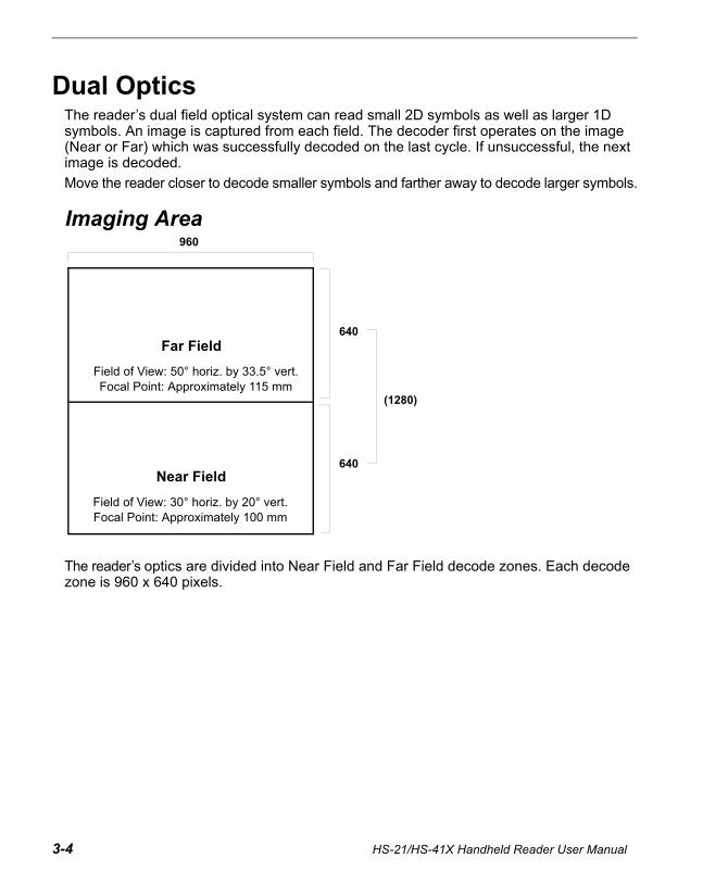
Dual OpticsThe reader’s dual field optical system can read small 2D symbols as well as larger 1D symbols. An image is captured from each field. The decoder first operates on the image (Near or Far) which was successfully decoded on the last cycle. If unsuccessful, the next image is decoded.
Move the reader closer to decode smaller symbols and farther away to decode larger symbols.
Imaging Area
The reader’s optics are divided into Near Field and Far Field decode zones. Each decode zone is 960 x 640 pixels.
Far Field
Near Field
960
640
640
(1280)
Field of View: 30° horiz. by 20° vert.Focal Point: Approximately 100 mm
Field of View: 50° horiz. by 33.5° vert.Focal Point: Approximately 115 mm
3-4 HS-21/HS-41X Handheld Reader User Manual

Basic Operations
Dual Optics Examples
20 mil Data Matrix
5 mil Code 39
Dual Field
Far Field
Near Field
Dual Field
Far Field
Near Field
HS-21/HS-41X Handheld Reader User Manual 3-5

Operational FeedbackCondition Top LED Light Sound Vibration
Reader Successfully Powers Up Green LED flashes 1 Beep Handle Vibrates
Reader Successfully Enumerates with Host (via Cable)
Once enumerated, the green LED turns Off
1 Beep Handle Vibrates
Attempting to Decode Green LED is Off None No VibrationSuccessful Decode and Data Transfer via Cable Green LED flashes 1 Beep Handle Vibrates
Configuration Symbol Successfully Decoded and Processed
Green LED flashes 2 Beep Handle Vibrates
Configuration Symbol Successfully Decoded but Not Successfully Processed
Green LED flashes 4 Beeps Handle Vibrates
3-6 HS-21/HS-41X Handheld Reader User Manual

4 CommunicationsContents
This section explains how to set up communications between the reader and a host.
With Microscan’s ESP (Easy Setup Program), configuration changes can be made in the ESP tree controls and then sent and saved to the reader. The Data Matrix symbols in this section can also be decoded to configure the reader’s Communications parameters.
Communications by ESP.............................................................................................................. 4-2Communications Overview........................................................................................................... 4-3USB Interface ............................................................................................................................... 4-4RS-232 Interface .......................................................................................................................... 4-5Preamble ...................................................................................................................................... 4-7Postamble..................................................................................................................................... 4-8Preamble and Postamble by ESP ................................................................................................ 4-9Keyboard Mapping ..................................................................................................................... 4-10Communications Mode............................................................................................................... 4-11USB Keyboard Rate ................................................................................................................... 4-13RS-232 ....................................................................................................................................... 4-14Text Command Timeout ............................................................................................................. 4-15
HS-21/HS-41X Handheld Reader User Manual 4-1

Communications by ESP
Communications by ESP
Click this button to bring up the App Mode view, then click the Communication tab.
To open nested options, single-click the +.
To change a setting, double-click the setting and use your cursor to scroll through the options.
4-2 HS-21/HS-41X Handheld Reader User Manual

Communications
HS-21/HS-41X Handheld Reader User Manual 4-3
Communications OverviewWhenever you default the reader, it will return to the default settings of whichever interface you are using. Defaulting the reader does not remove preamble and postamble formatting. The reader is in USB Native (HID) by default.
USBWith USB communications, the reader connects directly to the host’s USB port from which it draws its power. Data is displayed by any open Windows-based program that can capture text in USB Keyboard Mode.
RS-232With RS-232 communications the reader communicates with the host through a communications program such as ESP’s Terminal.
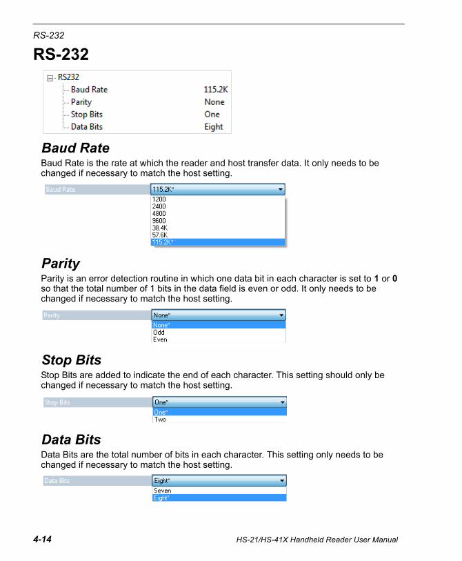
Default settings for establishing RS-232 communications are:
Baud Rate: 115.2K
Parity: None
Stop Bits: 1
Data Bits: 8

USB Interface
USB InterfaceThe reader is in USB Native (HID) by default.
USB Native (HID)This mode is the standard way of transferring unformatted, unpacketized data to the reader through the USB port.
USB Keyboard Mode (Windows)Data is output as keyboard sequences.
USB Virtual COM One-Way ModeThis mode allows a reader in a USB configuration to function as a virtual serial COM port. This mode requires installation of a USB Virtual COM driver, which is available from Microscan by request.
4-4 HS-21/HS-41X Handheld Reader User Manual

Communications
RS-232 InterfaceEnabling RS-232 Interface will disable USB communications and require you to default the reader or read the USB Keyboard Mode symbol to return to USB.
Baud Rate (RS-232)Baud Rate is the rate at which the reader and host transfer data. It only needs to be changed if necessary to match the host setting.
1200
2400
4800
9600
19.2K
38.4K
57.6K
115.2K (Default)
HS-21/HS-41X Handheld Reader User Manual 4-5

RS-232 Interface
Parity (RS-232)Parity is an error detection routine in which one data bit in each character is set to 1 or 0 so that the total number of 1 bits in the data field is even or odd. It only needs to be changed if necessary to match the host setting.
Data Bits (RS-232)Data Bits are the total number of bits in each character. This setting only needs to be changed if necessary to match the host setting.
None (Default) Odd Even
8 Data Bits (Default) 7 Data Bits
4-6 HS-21/HS-41X Handheld Reader User Manual

Communications
PreambleA preamble is a character or series of characters that is added to the beginning of a decoded data string. Preamble characters will appear in the order that they are enabled (left to right). For example, if you enable a comma and then a space, and then decode a symbol containing the data ‘ABC’, your output will look like this:
, ABC
The only limit to the number of preambles enabled is the total memory size available.
Set the desired preamble by reading the appropriate symbol below.
Comma Space Tab (RS-232 Only)
Carriage Return Line Feed (RS-232 Only)
Erase Preamble and Postamble Data
Tab (USB Keyboard Only) Erase (None)
HS-21/HS-41X Handheld Reader User Manual 4-7

Postamble
4-8 HS-21/HS-41X Handheld Reader User Manual
PostambleA postamble is a character or series of characters that is added to the end of a decoded data string. Postamble characters will appear in the order that they are enabled (left to right). For example, if you enable a space and then a comma, and then decode a symbol containing the data ‘ABC’, your output will look like this:
ABC ,
The only limit to the number of postambles enabled is the total memory size available.
Set the desired postamble by reading the appropriate symbol below.
Erase Preamble and Postamble Data
Line Feed (RS-232 Only)
Carriage Return (RS-232 Only)
Comma
Carriage Return Line Feed (RS-232 Only)
Space Tab (RS-232 Only)
Erase (None)
Tab (USB Keyboard Only)
Enter (USB Keboard Only)

Communications
Preamble and Postamble by ESPCharacters can also be added to the beginning and end of data strings using ESP. There are a few different ways to do this, using the interface shown below.
You will see the Communications tree control on the left, and the Preamble/Postamble interface on the right.
Scroll through a list of all preamble and postamble options, and then click Insert.
In addition to typing directly in the text fields and selecting from the dropdown menu, you can also click any of these preset buttons to set a preamble or postamble.
Save pre- and postamble settings and send them to the reader.
When you type ASCII characters directly into the Preamble or Postamble text fields and then click Send to Reader, those preamble or postamble characters are enabled and will appear in data output.
HS-21/HS-41X Handheld Reader User Manual 4-9

Keyboard Mapping
4-10 HS-21/HS-41X Handheld Reader User Manual
Keyboard MappingThe Keyboard Mapping feature provides alternatives for keyboards that do not conform to U.S. English mapping.
Note: Universal Keyboard mapping is slightly slower than the other language-specific options, because it maps data by reference to the full set of ASCII characters. The advantage of Universal Keyboard mapping is that it allows any language and keyboard layout to be mapped.
Important: Keyboard Mapping is not to be confused with USB Keyboard Mode, which has an entirely different function—namely to enable USB cabled communications.
Keyboard Mapping by ESP
U.S., No Leading 0 (Default) U.S. with Leading 0 U.S., Ctrl + Char.
French German Japanese
Universal Custom Belgian
Swiss

Communications
HS-21/HS-41X Handheld Reader User Manual 4-11
Communications ModeSome ESP Communications options are unique to the software, and do not have corresponding programming symbols. These options are explained below.
Reader Packet Format
Data that is sent from the reader to the host in Raw format is sent without packet framing or check characters. One-Way communication is in a raw format, no response is expected from the host, and data is not resent.
Packetized data is sent with framing (a preamble communicating the amount of data to be transmitted, and a postamble containing error detection) and check characters, and a response is expected from the host. Two-Way communication is in packet format.
Reader to Host Packet Size
The Reader to Host Packet Size is the amount of data (in bytes) that is sent to the host in packet format. This feature allows you to set the maximum allowable packet size.
Expect Host Response
When Expect Host Response is enabled, the reader will re-transmit data if it doesn’t receive acknowledgement from the host.
Reader Send Retry Count
Reader Send Retry Count sets the number of times the reader will re-transmit data before abandoning further send attempts. The minimum retry count is 1, which represents the initial transmission.
Host Acknowledgement Timeout
The Host Acknowledgement Timeout is the amount of time (in seconds) that the reader will wait for an acknowledgement from the host before re-sending data.

Communications Mode
Text CommandsWhen the Text Commands feature is enabled, the reader can accept text commands via RS-232 connections and USB Virtual COM modes.
Note: Text Commands are not supported in USB HID Mode.
Text Commands by ESP
Entering Magic SequenceThe magic sequence is ;>PA followed by a numeric value of 1, 3, or 7.
1 = Enable Text Commands3 = Enabled; Suppress Echo7 = Enabled; Suppress Echo and ResponsesIn the example below, the magic sequence entered will Enable Text Commands and Suppress Echo and Responses.
Enable Text Commands
Disable Text Commands (Default)
When Text Commands are set to Enabled; Suppress Echo, text that a user enters in the Terminal will not be shown. When Text Commands are set to Enabled; Suppress Echo and Responses, neither user-entered data or reader responses will be shown, and only decoded symbol data will appear in the Terminal.See Terminal Right-Click Menu for a way to change Echo settings directly in the Terminal view.
When Magic Sequence is enabled, it allows the user to enable Text Commands by entering a predetermined series of keystrokes.
Enter the magic sequence in this text field and click Send.
Once the magic sequence has been sent, you can send text commands from the same text field.
4-12 HS-21/HS-41X Handheld Reader User Manual

Communications
USB Keyboard Rate
Requests that the host polls the USB reader at the rate specified (1 to 255 ms).
HS-21/HS-41X Handheld Reader User Manual 4-13
RS-232
RS-232
Baud RateBaud Rate is the rate at which the reader and host transfer data. It only needs to be changed if necessary to match the host setting.
ParityParity is an error detection routine in which one data bit in each character is set to 1 or 0 so that the total number of 1 bits in the data field is even or odd. It only needs to be changed if necessary to match the host setting.
Stop BitsStop Bits are added to indicate the end of each character. This setting should only be changed if necessary to match the host setting.
Data BitsData Bits are the total number of bits in each character. This setting only needs to be changed if necessary to match the host setting.
4-14 HS-21/HS-41X Handheld Reader User Manual

Communications
Text Command TimeoutText Command Timeout allows you to set the maximum time during which a complete text command from the host must be received. Pending text command data is discarded when the timeout is exceeded.
HS-21/HS-41X Handheld Reader User Manual 4-15

Text Command Timeout
4-16 HS-21/HS-41X Handheld Reader User Manual

HS-21/HS-41X Handheld Reader User Manual 5-1
5 Read CycleContents
After you’ve established communications you will need to address the spatial and timing parameters associated with your application. This section explains those parameters. The Data Matrix symbols in this section can also be decoded to configure Read Cycle parameters.
Read Cycle by ESP...................................................................................................................... 5-2External Trigger............................................................................................................................ 5-3Default Continuous Event............................................................................................................. 5-4Maximum Decodes per Read....................................................................................................... 5-5Read Cycle Timeout..................................................................................................................... 5-6Ignore Duplicate Symbol Timeout ................................................................................................ 5-7Targeting Zone Tolerance ............................................................................................................ 5-8Morphological Preprocessing ....................................................................................................... 5-9Camera Settings......................................................................................................................... 5-10

5-2 HS-21/HS-41X Handheld Reader User Manual
Read Cycle by ESP
Read Cycle by ESP
To change a setting, double-click the setting and use your cursor to scroll through the options.
Click this button to bring up the App Mode view, and then click the Read Cycle tab.
To open nested options, single-click the +.

HS-21/HS-41X Handheld Reader User Manual 5-3
Read Cycle
External TriggerThe External Trigger parameter allows you to determine reader behavior when triggered externally.
Show TargetThe target LEDs will illuminate when the reader is triggered externally.
Read Both Fields (Default)Both Near Field and Far Field will be activated to capture an image when the reader is triggered externally.
Read Near FieldNear Field will be activated to capture an image when the reader is triggered externally.
Read Far FieldFar Field will be activated to capture an image when the reader is triggered externally.
Read Primary FieldWhen Read Primary Field is selected, the most recent field to have produced a Good Read (Near Field or Far Field) will be activated to capture an image when the reader is triggered externally.
Trigger ActiveWhen an external trigger is active, the reader will either decode once and stop or decode continuously, depending on how this parameter is set. Trigger Active is set to Read Once by default.
Important: Ignore Duplicate Symbol Timeout should be set to a value greater than 0 when Trigger Active is set to Continuous Read.

5-4 HS-21/HS-41X Handheld Reader User Manual
Default Continuous Event
Default Continuous EventThis parameter allows you to determine the default state of the reader.
Idle (Default)When Default Continuous Event is set to Idle, the reader will remain inactive until triggered.
Show TargetWhen Default Continuous Event is set to Show Target, the reader will display the target LEDs but remain inactive until triggered externally.
Motion DetectWhen Default Continuous Event is set to Motion Detect, the reader will remain inactive until motion occurs in the field of view (if a symbol is hand-presented, for example).
Read Both FieldsBoth Near Field and Far Field will be continuously activated to capture an image.
Read Near FieldNear Field will be continuously activated to capture an image.
Read Far FieldFar Field will be continuously activated to capture an image.
Read Primary FieldWhen Read Primary Field is selected, the most recent field to have produced a Good Read (Near Field or Far Field) will be continuously activated to capture an image.
Event DelayThe default Event Delay is 0.100 seconds.

HS-21/HS-41X Handheld Reader User Manual 5-5
Read Cycle
Maximum Decodes per ReadMaximum Decodes per Read allows you to set how many decodes can be performed in a single read cycle.

5-6 HS-21/HS-41X Handheld Reader User Manual
Read Cycle Timeout
Read Cycle TimeoutRead Cycle Timeout determines the duration of the read cycle. The default Read Cycle Timeout is 0.500 seconds.
HS-21/HS-41X Handheld Reader User Manual 5-7
Read Cycle
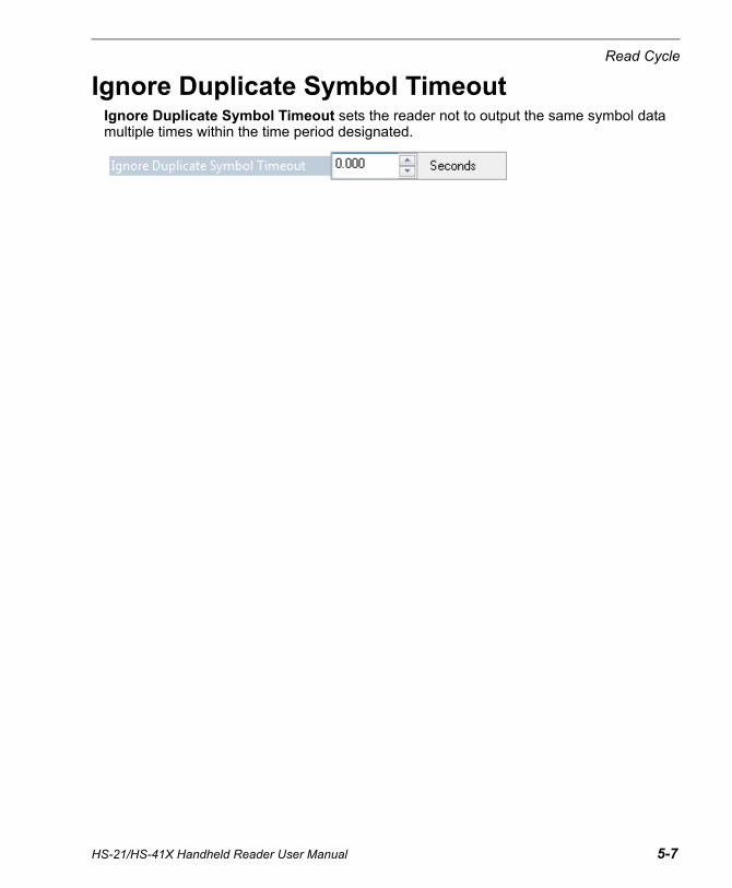
Ignore Duplicate Symbol TimeoutIgnore Duplicate Symbol Timeout sets the reader not to output the same symbol data multiple times within the time period designated.

5-8 HS-21/HS-41X Handheld Reader User Manual
Targeting Zone Tolerance
Targeting Zone ToleranceTargeting Zone Tolerance is particularly useful in environments where closely spaced symbols of various sizes need to be targeted. It allows the reader to narrow the field of view relative to the size of a symbol, and to determine the distance the target must be from the symbol for a decode event to occur.
See Window of Interest for more precise control of the active pixel area.
The default Targeting Zone Tolerance is 1600%.
Formula for calculating Targeting Zone Tolerance:
2 x distance from target to symbol (in pixels) / symbol width or height (in pixels) x 100

HS-21/HS-41X Handheld Reader User Manual 5-9
Read Cycle
Morphological PreprocessingMorphological Preprocessing allows you to select the method for processing captured images, and to choose the operator size for that method. It is set to None by default.
Note: This feature is only available in the HS-41X Handheld Reader.
ErodeErode increases the dark cell size of a symbol. Useful for increasing the dark cell size of a dark-on-light Data Matrix symbol.
DilateDilate increases the light cell size of a symbol. Useful for increasing the light cell size of a light-on-dark Data Matrix symbol.
SizeSize determines the size of the area or “pixel neighborhood” (measured in pixels) in which the morphological operation is being performed.

5-10 HS-21/HS-41X Handheld Reader User Manual
Camera Settings
Camera SettingsCamera Settings allow you to set AGC Sampling Mode, to set the percentage values for Illumination, Exposure, and Gain, to set the AGC Frame Adjust Count, and also to define Window of Interest dimensions.
AGC Sampling ModeWhen AGC Sampling Mode is set to Automatic (default), each time a No Read occurs, the reader adjusts the gain and exposure for the next capture to optimize symbol contrast.
The values for Illumination, Exposure, and Gain can be set to any value between 0% and 100%. The default values are shown below.
AGC Frame Adjust CountAutomatic Gain Control (AGC) is a system that controls gain in order to maintain high performance over a range of input levels. Gain is essentially the ratio of output to input. Gain settings affect how the reader decodes symbols and captures images.
AGC Frame Adjust Count sets the number of image frames captured and discarded before the main image capture. This feature gives the gain control time to adjust.

HS-21/HS-41X Handheld Reader User Manual 5-11
Read Cycle
Window of InterestThe active pixel area of the image sensor is called the Window of Interest (WOI). The WOI allows the user to select an area of the field of view in which the desired symbol is located.
The programmable window of interest increases decode speed, improves threshold, and makes it easy to select specific symbols from among several in the field of view. The user provides the upper-left pixel location and the size of the window to define the Window of Interest.
Window of Interest can also be controlled using a graphic interface in ESP.
High Density
Wide

5-12 HS-21/HS-41X Handheld Reader User Manual

6 SymbologiesContents
This section describes the various symbol types that can be decoded by the HS-21 and HS-41X. The Data Matrix symbols in this section can also be decoded to configure Symbologies parameters.
Symbologies by ESP.................................................................................................................... 6-2Data Matrix ................................................................................................................................... 6-3QR Code ...................................................................................................................................... 6-4Aztec ............................................................................................................................................ 6-5Code 39........................................................................................................................................ 6-6Code 128...................................................................................................................................... 6-7BC412 .......................................................................................................................................... 6-8Code 93........................................................................................................................................ 6-9Codabar...................................................................................................................................... 6-10Interleaved 2 of 5........................................................................................................................ 6-11UPC............................................................................................................................................ 6-12Postal ......................................................................................................................................... 6-13Pharmacode ............................................................................................................................... 6-14GS1 DataBar .............................................................................................................................. 6-16PDF417 ...................................................................................................................................... 6-17MicroPDF417 ............................................................................................................................. 6-18Composite .................................................................................................................................. 6-19Symbology Identifier................................................................................................................... 6-20
HS-21/HS-41X Handheld Reader User Manual 6-1

Symbologies by ESP
Symbologies by ESP
To change a setting, double-click the setting and use your cursor to scroll through the options.
Click this button to bring up the App Mode view, and then click the Symbologies tab.
To open nested options, single-click the +.
6-2 HS-21/HS-41X Handheld Reader User Manual

Symbologies
Data Matrix
Data Matrix Enabled (Default) Data Matrix Disabled
Sample Data Matrix Symbol
If you disable the Data Matrix symbology, programming symbols will not be decodable by the reader and Data Matrix will need to be re-enabled using ESP.
Use the Data Matrix Disabled programming symbol with caution.
HS-21/HS-41X Handheld Reader User Manual 6-3

QR Code
QR Code
QR Code Inverse and Standard Enabled QR Code Disabled
QR Code and Micro QR Code Enabled
Sample QR Code Symbol Sample Micro QR Code Symbol
6-4 HS-21/HS-41X Handheld Reader User Manual

Symbologies
Aztec
Aztec Enabled Aztec Disabled (Default)
Sample Aztec Symbol
HS-21/HS-41X Handheld Reader User Manual 6-5

Code 39
Code 39
Code 39 Disabled Code 39 Enabled (Default)
Code 39 Enable Checksum Code 39 Disable Checksum (Default)
Code 39 Enable Checksum and Strip from Result
Code 39 Extended Code 39 ExtendedFull ASCII Enabled Full ASCII Disabled (Default)
Sample Code 39 Symbol
6-6 HS-21/HS-41X Handheld Reader User Manual

Symbologies
Code 128
Code 128 Enabled (Default) Code 128 Disabled
Sample Code 128 Symbol
HS-21/HS-41X Handheld Reader User Manual 6-7

BC412
BC412
BC412 Enabled (Default) BC412 Disabled
Sample BC412 Symbol
6-8 HS-21/HS-41X Handheld Reader User Manual

Symbologies
Code 93
Code 93 Enabled (Default) Code 93 Disabled
Sample Code 93 Symbol
HS-21/HS-41X Handheld Reader User Manual 6-9

Codabar
Codabar
Codabar Enabled (Default) Codabar Disabled
Codabar Checksum Enabled Codabar Checksum Disabled (Default)
Codabar Checksum Enabled and Strip from Result
Sample Codabar Symbol
6-10 HS-21/HS-41X Handheld Reader User Manual

Symbologies
HS-21/HS-41X Handheld Reader User Manual 6-11
Interleaved 2 of 5
Interleaved 2 of 5 Enabled (Default) Interleaved 2 of 5 Disabled
Interleaved 2 of 5 Checksum Enabled Interleaved 2 of 5 Checksum Disabled (Default)
Interleaved 2 of 5 Checksum Enabled and Strip from Result
Interleaved 2 of 5 Two Digit Minimum Interleaved 2 of 5 Four Digit Minimum
Interleaved 2 of 5 Six Digit Minimum (Default)
Sample Interleaved 2 of 5 Symbol

UPC
UPC
UPC Enabled (Default) UPC Disabled
EAN Status Enabled (Default) EAN Status Disabled
UPC-E as UPC-A Enabled UPC-E as UPC-A Disabled (Default)
Sample UPC-E Symbol
Sample UPC-A Symbol
6-12 HS-21/HS-41X Handheld Reader User Manual

Symbologies
Postal
Postal Enabled Postal Disabled (Default)
Supported Postal Symbologies
• USPS OneCode (4CB)
• POSTNET
• PLANET
• Japanese Post
• Australian Post
• Royal Mail
• KIX Code
Sample Postnet Symbol
Sample Royal Mail Symbol
HS-21/HS-41X Handheld Reader User Manual 6-13

Pharmacode
6-14 HS-21/HS-41X Handheld Reader User Manual
Pharmacode
Pharmacode Enabled Pharmacode Disabled (Default)
Fixed Symbol Length Enabled Fixed Symbol Length Disabled (Default)
Bar Width Status: Mixed (Default) Bar Width Status: All Narrow
Bar Width Status: All Wide Bar Width Status: Fixed Threshold
Direction: Forward (Default) Direction: Reverse

Symbologies
Fixed Symbol Length StatusWhen enabled, the reader will check the symbol length against the symbol length field. If disabled, any length will be considered valid.
Symbol LengthSpecifies the exact number of bars that must be present for the reader to recognize and decode the Pharmacode symbol.
Minimum BarsSets the minimum number of bars that a Pharmacode symbol must have to be considered valid.
Bar Width StatusIf set to Mixed, the reader will autodiscriminate between narrow bars and wide bars. If set to All Narrow, all bars will be considered as narrow bars. If set to All Wide, all bars will be considered as wide bars. If set to Fixed Threshold, it will use the fixed threshold value to determine whether the bars are narrow or wide. The Bar Width Status setting will be ignored when the reader is able to tell the difference between the narrow and the wide bars.
DirectionSpecifies the direction in which a symbol can be read.
Fixed Threshold ValueUsed when Bar Width Status is set to Fixed Threshold. Defines the minimum difference in pixels that will distinguish a narrow bar from a wide bar.
Sample Pharmacode Symbol
HS-21/HS-41X Handheld Reader User Manual 6-15

GS1 DataBar
GS1 DataBar
All GS1 DataBar Enabled (Default) All GS1 DataBar Disabled
GS1 DataBar Expanded Enabled GS1 DataBar Limited Enabled
GS1 DataBar-14 Enabled
Sample DataBar-14 Limited Symbol
Sample DataBar-14 Stacked Symbol Sample DataBar Expanded Symbol
Sample DataBar-14 Symbol
6-16 HS-21/HS-41X Handheld Reader User Manual
Symbologies
PDF417
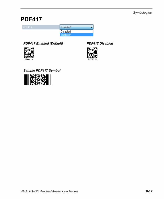
PDF417 Enabled (Default) PDF417 Disabled
Sample PDF417 Symbol
HS-21/HS-41X Handheld Reader User Manual 6-17

MicroPDF417
MicroPDF417
MicroPDF417 Disabled (Default) MicroPDF417 Enabled
Sample MicroPDF417 Symbol
6-18 HS-21/HS-41X Handheld Reader User Manual

Symbologies
CompositeComposite consists of a 1D component associated with an adjacent 2D component. A successful decode is required for both the 1D and 2D components before the reader outputs a result. When Composite is enabled, the unit decodes the 1D component first.
Important: EAN-8, EAN-13, UPC-A, and UPC-E cannot be decoded individually when Composite is enabled.
Maximum Decodes per ReadMaximum Decodes per Read represents the maximum number of candidate symbols in the field of view (1 - 100) that can be decoded during a read cycle. Note that decode speed will decrease as the Maximum Decodes per Read value is increased.
Composite Disabled (Default) Composite Enabled
Sample Composite Symbol
HS-21/HS-41X Handheld Reader User Manual 6-19

Symbology Identifier
Symbology IdentifierWhen Symbology Identifier is enabled, an AIM (Association for Automatic Identification and Mobility) preamble is added to decoded data output (see the AIM Symbology Identifiers list). This preamble identifies what kind of symbology has been decoded.
AIM Symbology IdentifiersA Code 39
C Code 128
d Data Matrix
e GS1 DataBar / Composite
E UPC/EAN
F Codabar
G Code 93
I Interleaved 2 of 5
L PDF417 / MicroPDF417
Q QR Code / Micro QR Code
X Other (Pharmacode)
z Aztec
6-20 HS-21/HS-41X Handheld Reader User Manual

7 I/O ParametersContents
This section includes instructions on setting up conditions for changing input/output electrical transitions for control of the reader’s internal and external devices. A discrete I/O (in/out) signal is an electrical transition from one voltage level to another so that digital switching can occur. The Data Matrix symbols in this section can also be decoded to configure I/O parameters.
I/O Parameters by ESP ................................................................................................................ 7-2No Read Notification .................................................................................................................... 7-3Targeting ...................................................................................................................................... 7-4Beeper.......................................................................................................................................... 7-5Vibrate .......................................................................................................................................... 7-6Button Stay-Down Time ............................................................................................................... 7-7Motion Detect Event ..................................................................................................................... 7-8Image Quality ............................................................................................................................... 7-9Data Validation ........................................................................................................................... 7-10
HS-21/HS-41X Handheld Reader User Manual 7-1

I/O Parameters by ESP
I/O Parameters by ESP
To change a setting, double-click the setting and use your cursor to scroll through the options.
Click this button to bring up the App Mode view, and then click the Read Cycle tab.
To open nested options, single-click the +.
7-2 HS-21/HS-41X Handheld Reader User Manual

I/O Parameters
No Read NotificationNo Read Notification allows you to enable or disable user feedback alerting you when a symbol is not decoded successfully.
The No Read message output is ap/r, indicating that the reader did not decode the symbol.
HS-21/HS-41X Handheld Reader User Manual 7-3

Targeting
7-4 HS-21/HS-41X Handheld Reader User Manual
TargetingThe Targeting parameter allows you to turn the targeting LEDs on or off. They are on by default.
Read the configuration symbols below to enable or disable Targeting.
Targeting Off Targeting On

I/O Parameters
BeeperThe Beeper parameters allow you to set the Volume, Duration, and Separation of the beep, and whether or not it will beep on a Good Read.
Beeper volume is 100% by default, 0.100 seconds Duration by default, and 0.100 seconds Separation by default.
Beep on Good Read is enabled by default.
Read the configuration symbols below to enable or disable Beeper.
Beeper Off Beeper On
HS-21/HS-41X Handheld Reader User Manual 7-5
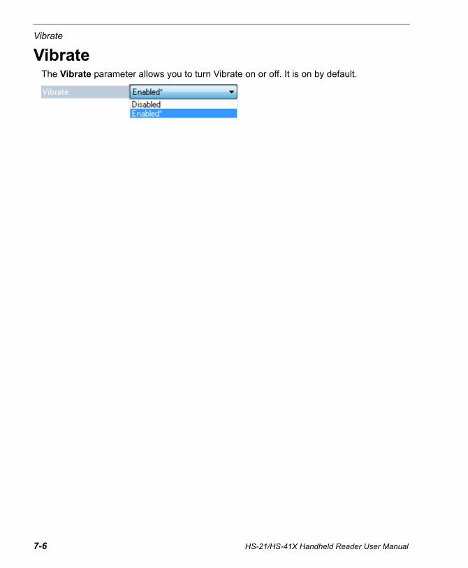
Vibrate
VibrateThe Vibrate parameter allows you to turn Vibrate on or off. It is on by default.
7-6 HS-21/HS-41X Handheld Reader User Manual

I/O Parameters
Button Stay-Down TimeButton Stay-Down Time sets the amount of time (in seconds) that the reader will continue to process the current “decode symbol” event. The reader will behave as if the trigger is being activated for this specified amount of time.
HS-21/HS-41X Handheld Reader User Manual 7-7

Motion Detect Event
Motion Detect EventMotion Detect Event allows you to determine the reader's behavior when motion is detected in the field of view.
Show TargetThe target LEDs will illuminate when a motion detect event occurs.
Read Both Fields (Default)Both Near Field and Far Field will be activated to capture an image when a motion detect event occurs.
Read Near FieldNear Field will be activated to capture an image when a motion detect event occurs.
Read Far FieldFar Field will be activated to capture an image when a motion detect event occurs.
Read Primary FieldWhen Read Primary Field is selected, the most recent field to have produced a Good Read (Near Field or Far Field) will be activated to capture an image when a motion detect event occurs.
Read the configuration symbols below to enable or disable Motion Detection.
Motion Sensitivity allows you to determine the sensitivity of motion detection (lower is more sensitive - 5 is default).Motion Detect Start Delay allows you to set the amount of delay before a motion detect event occurs. (0 seconds is default.)
Motion Detection OnStart Delay 0
Motion Detection Off Motion Detection On, Start Delay 500 ms
7-8 HS-21/HS-41X Handheld Reader User Manual

I/O Parameters
Image QualityImage Quality allows you to determine the quality of images that are output from image captures. Image Quality is set to 50% by default.
HS-21/HS-41X Handheld Reader User Manual 7-9

Data Validation
Data ValidationData Validation is used to confirm that a decoded string from the imager has complied with a particular company, industry, or ISO standard. HS-21/HS-41X Data Validation is compliant with Department of Defense Unique Identification and ISO/IEC 15434 (Information Technology – Transfer Syntax for High-Capacity ADC Media) requirements.
Unique IdentificationUnique Identification is a mandatory Department of Defense (DoD) requirement on all solicitations issued January 1, 2004 or later. This policy mandates the use of Unique Item Identifiers (UIIs) encoded within Data Matrix symbols on equipment and parts procured by DoD. The HS-21/HS-41X complies with Department of Defense Standard Practice Identification (MIL-STD-130).
Once the imager decodes the Data Matrix symbol, and if Unique Item Identifier (UII), Current Part Number (CPN), and Lot/Batch Number (LBN) are turned on, the HS-21/HS-41X checks the ISO/IEC 15434 syntax with ISO/IEC 15418 (ANSI MH10.8.2 – AI and DI) and ISO/IEC 21849 (ATA – TEI) semantics to construct the UII, CPN, and LBN.
Unique Identification FeaturesThe following data output options are applicable to Data Matrix ECC 200 symbols only and have no effect on other symbologies.
UII Enabled Allows the imager to read only message streams encoded in Data Matrix ECC 200 symbols, then to construct and output a UII string. The message streams include validation of Unique Item Identifier (UII), Current Part Number (CPN), and Lot/Batch Number (LBN) strings. When the imager decodes a symbol but the symbol data does not compy with UII format, it will stop capturing images and the green LED will illuminate without beeping, vibrating, or outputing the string.
UII Enabled withPass Through
Allows the imager to read UII messages in Data Matrix ECC 200 symbols and non-UII messages in any type of symbols. The imager’s behavior is the same as with UII Enabled.
UII Enabled withError Messages
Allows the imager to read UII messages in Data Matrix ECC 200 symbols and output detailed information such as construction type, data components, or error messages. The imager’s behavior is the same as with UII Enabled.
Data ValidationDisabled
Disables both UII and ISO/IEC 15434 data validation.
7-10 HS-21/HS-41X Handheld Reader User Manual

I/O Parameters
Unique Identification Output Examples
UII EnabledUII:UN123456789ABCDEFG
CPN:87654321
LBN:87654321
UII:12345678 CPN:87654321
UII:12345678 LBN:87654321
UII Enabled with Pass ThroughUII:UN123456789ABCDEFG
CPN:87654321
LBN:87654321
UII:12345678 CPN:87654321
UII:12345678 LBN:87654321
DATA:Microscan Precision Data Acquisition and Control Solutions
UII Enabled with Error MessagesUII:UN123456789ABCDEFG;Construct_1;25SUN123456789ABCDEFG;;;;;;
CPN:87654321;PNR;PNR 87654321;;;;;;
LBN:87654321;30T;30T87654321;;;;;;
UII:12345678 CPN:87654321;Construct_1_2/PNR;UID 12345678;PNR 87654321;;;;;
UII:12345678 LBN:87654321;Construct_1/30T;25S12345678;30T87654321;;;;;
(15434 ERROR: HEADER - 1ST POSITION);Microscan Precision Data Acquisition and Control Solutions;;;;;;;
Data Validation DisabledThe imager will return to normal output behavior without performing data validation.
HS-21/HS-41X Handheld Reader User Manual 7-11

Data Validation
ISO/IEC 15434ISO/IEC 15434 specifies a transfer structure, syntax, and coding of messages and data formats when using high capacity automatic data capture (ADC) technologies.
The following ISO/IEC 15434 data output options are applicable to Data Matrix ECC 200 symbols only and have no effect on other symbologies.
ISO/IEC 15434 Output Examples
ISO/IEC 15434 Enabled(15434);05;0100061414199999;211A0B9C3D6;;;;;
(15434);06;7L0A1B3C;1P4202435;S10936;;;;
(15434);06;17V0A1B2;1P4202435;S10936;;;;
ISO/IEC 15434 Enabled with Error Messages(15434);05;0100061414199999;211A0B9C3D6;;;;;
(15434);06;7L0A1B3C;1P4202435;S10936;;;;
(15434);06;17V0A1B2;1P4202435;S10936;;;;
(15434 ERROR: HEADER - 3RD POSITION);[)<▲DD↔CAG 12345↔SER 67890123▲♦;;;;;;;
(15434 ERROR: TRAILER - END OF TRANSMISSION);[)>▲12↔CAG 12345↔SER 67890123▲♣;;;;;;;
(15434 ERROR: HEADER - GROUP SEPARATOR);[)>▲12▲CAG 12345♦029SER 67890123▲♦;;;;;;;
Data Validation DisabledThe imager will return to normal output behavior without performing data validation.
ISO/IEC 15434Enabled
Allows the imager to read only ISO/IEC 15434-compliant message streams in Data Matrix ECC 200 symbols then output the ISO/IEC 15434 string. This implementation only checks the header/trailer format and proper format indicator (00-99 and DD). The output string has a prefix, a format indicator, and data components.
ISO/IEC 15434Enabled with Error
Messages
Allows the imager to read only ISO/IEC 15434-compliant messages in Data Matrix ECC 200 symbols and output detailed information such as prefix, format indicator, data components, or error messages.
Data ValidationDisabled
Disables both UII and ISO/IEC 15434 data validation.
7-12 HS-21/HS-41X Handheld Reader User Manual
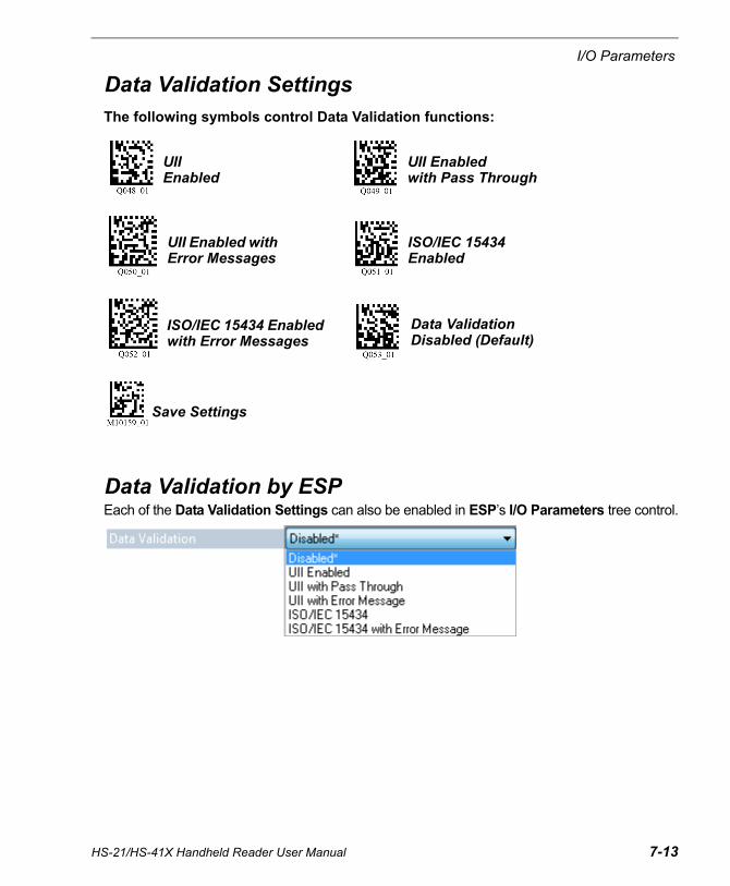
I/O Parameters
Data Validation SettingsThe following symbols control Data Validation functions:
Data Validation by ESPEach of the Data Validation Settings can also be enabled in ESP’s I/O Parameters tree control.
Data Validation Disabled (Default)
Save Settings
UII Enabled with Error Messages
ISO/IEC 15434 Enabled
ISO/IEC 15434 Enabled with Error Messages
UII Enabled
UII Enabled with Pass Through
HS-21/HS-41X Handheld Reader User Manual 7-13
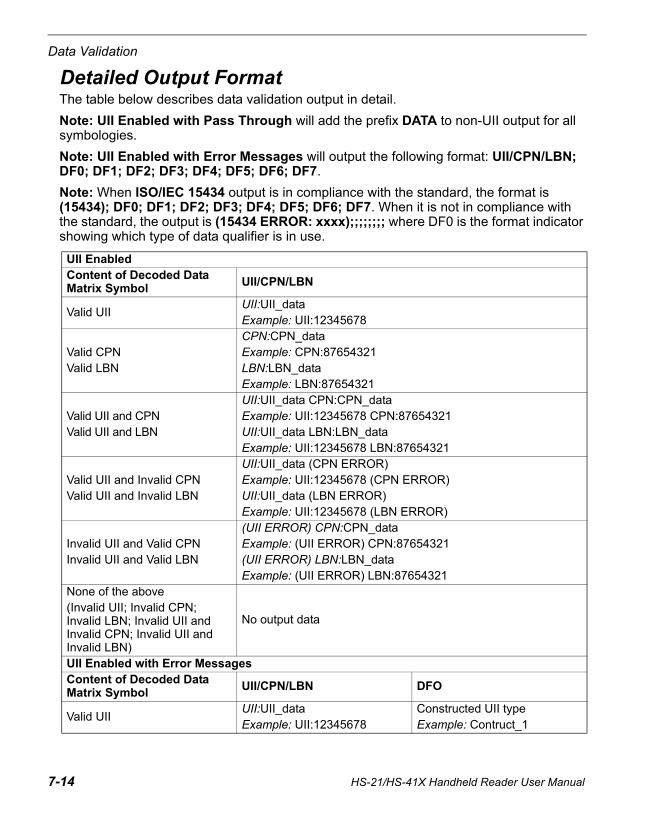
Data Validation
Detailed Output FormatThe table below describes data validation output in detail.
Note: UII Enabled with Pass Through will add the prefix DATA to non-UII output for all symbologies.
Note: UII Enabled with Error Messages will output the following format: UII/CPN/LBN; DF0; DF1; DF2; DF3; DF4; DF5; DF6; DF7.
Note: When ISO/IEC 15434 output is in compliance with the standard, the format is (15434); DF0; DF1; DF2; DF3; DF4; DF5; DF6; DF7. When it is not in compliance with the standard, the output is (15434 ERROR: xxxx);;;;;;;; where DF0 is the format indicator showing which type of data qualifier is in use.
UII EnabledContent of Decoded Data Matrix Symbol UII/CPN/LBN
Valid UIIUII:UII_dataExample: UII:12345678
Valid CPNValid LBN
CPN:CPN_dataExample: CPN:87654321LBN:LBN_dataExample: LBN:87654321
Valid UII and CPNValid UII and LBN
UII:UII_data CPN:CPN_dataExample: UII:12345678 CPN:87654321UII:UII_data LBN:LBN_dataExample: UII:12345678 LBN:87654321
Valid UII and Invalid CPNValid UII and Invalid LBN
UII:UII_data (CPN ERROR)Example: UII:12345678 (CPN ERROR)UII:UII_data (LBN ERROR)Example: UII:12345678 (LBN ERROR)
Invalid UII and Valid CPNInvalid UII and Valid LBN
(UII ERROR) CPN:CPN_dataExample: (UII ERROR) CPN:87654321(UII ERROR) LBN:LBN_dataExample: (UII ERROR) LBN:87654321
None of the above(Invalid UII; Invalid CPN; Invalid LBN; Invalid UII and Invalid CPN; Invalid UII and Invalid LBN)
No output data
UII Enabled with Error MessagesContent of Decoded Data Matrix Symbol
UII/CPN/LBN DFO
Valid UIIUII:UII_dataExample: UII:12345678
Constructed UII typeExample: Contruct_1
7-14 HS-21/HS-41X Handheld Reader User Manual

I/O Parameters
Valid CPNValid LBN
CPN:CPN_dataExample: CPN:87654321LBN:LBN_dataExample: LBN:87654321
Constructed CPN typeExample: PNRConstructed LBN typeExample: 30T
Valid UII and CPNValid UII and LBN
UII:UII_data CPN:CPN_dataExample: UII:12345678 CPN:87654321UII:UII_data LBN:LBN_dataExample: UII:12345678 LBN:87654321
Constructed UII/CPN typeExample: Construct_1/PNRConstructed UII/LBN typeExample: Construct_1/30T
Valid UII and Invalid CPNValid UII and Invalid LBN
UII:UII_data (30P ERROR: xxxx)UII:UII_data (PNR ERROR: xxxx)UII:UII_data (240 ERROR: xxxx)UII:UII_data (30T ERROR: xxxx)
Constructed UII typeExample: Construct_1
Invalid UII and Valid CPNInvalid UII and Valid LBN
(UII ERROR: xxxx) CPN:CPN_data(UII ERROR: xxxx) LBN:LBN_data
Constructed CPN type:30P, PNR, 240Constructed LBN type:30T
Invalid UII
(UII ERROR: xxxx)(15434 ERROR: xxxx)Example: (UII ERROR: DATA ELEMENT CHARACTER)
Original decoded data
Invalid CPNInvalid LBN
(30P ERROR:xxxx)(PNR ERROR:xxxx)(240 ERROR:xxxx)(30T ERROR:xxxx)(15434 ERROR: xxxx)
Original decoded data
Invalid UII and Invalid CPNInvalid UII and Invalid LBN
(UII ERROR: xxxx) (30P ERROR: xxxx)(UII ERROR: xxxx) (PNR ERROR: xxxx)(UII ERROR: xxxx) (240 ERROR: xxxx)(UII ERROR: xxxx) (30T ERROR: xxxx)
Original decoded data
HS-21/HS-41X Handheld Reader User Manual 7-15
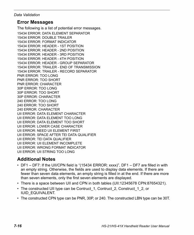
Data Validation
Error MessagesThe following is a list of potential error messages.15434 ERROR: DATA ELEMENT SEPARATOR15434 ERROR: DOUBLE TRAILER15434 ERROR: FORMAT INDICATOR15434 ERROR: HEADER - 1ST POSITION15434 ERROR: HEADER - 2ND POSITION15434 ERROR: HEADER - 3RD POSITION15434 ERROR: HEADER - 4TH POSITION15434 ERROR: HEADER - GROUP SEPARATOR15434 ERROR: TRAILER - END OF TRANSMISSION15434 ERROR: TRAILER - RECORD SEPARATORPNR ERROR: TOO LONGPNR ERROR: TOO SHORTPNR ERROR: CHARACTER30P ERROR: TOO LONG30P ERROR: TOO SHORT30P ERROR: CHARACTER240 ERROR: TOO LONG240 ERROR: TOO SHORT240 ERROR: CHARACTERUII ERROR: DATA ELEMENT CHARACTERUII ERROR: DATA ELEMENT TOO LONGUII ERROR: DATA ELEMENT TOO SHORTUII ERROR: LOWER CASE CHARACTERUII ERROR: NEED UII ELEMENT FIRSTUII ERROR: SPACE AFTER TEI DATA QUALIFIERUII ERROR: TEI DATA QUALIFIERUII ERROR: UII ELEMENT INCOMPLETEUII ERROR: WRONG FORMAT INDICATORUII ERROR: UII STRING TOO LONG
Additional Notes• DF1 – DF7: If the UII/CPN field is “(15434 ERROR: xxxx)”, DF1 – DF7 are filled in with
an empty string. Otherwise, the fields are used to display data elements. If there are fewer than seven data elements, an empty string is filled in at the end. If there are more than seven elements, only the first seven elements are displayed.
• There is a space between UII and CPN in both tables (UII:12345678 CPN:87654321).
• The constructed UII type can be Contruct_1, Contruct_2, Construct_1_2, or IUID_EQUIVALENT.
• The constructed CPN type can be PNR, 30P, or 240. The constructed LBN type can be 30T.
7-16 HS-21/HS-41X Handheld Reader User Manual

8 Advanced OperationsContents
This section introduces several settings that can be applied to speed up processing or improve readablility in various circumstances.
Continuous Read.......................................................................................................................... 8-2Mirroring ....................................................................................................................................... 8-3Motion Detection........................................................................................................................... 8-4Window of Interest........................................................................................................................ 8-5
HS-21/HS-41X Handheld Reader User Manual 8-1

Continuous Read
Continuous ReadRead the following symbols to enable or disable Continuous Read.
Continuous Read On Continuous Read Off
8-2 HS-21/HS-41X Handheld Reader User Manual
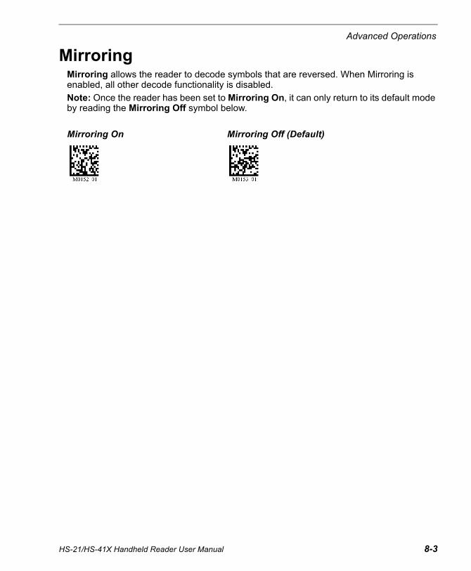
Advanced Operations
MirroringMirroring allows the reader to decode symbols that are reversed. When Mirroring is enabled, all other decode functionality is disabled.
Note: Once the reader has been set to Mirroring On, it can only return to its default mode by reading the Mirroring Off symbol below.
Mirroring On Mirroring Off (Default)
HS-21/HS-41X Handheld Reader User Manual 8-3

Motion Detection
8-4 HS-21/HS-41X Handheld Reader User Manual
Motion DetectionMotion Detection causes the reader to attempt a decode whenever it senses motion in its field of view.
Motion Detection by ESPMotion Detection settings can be refined further using the options in ESP.
Motion SensitivityThe reader’s sensitivity to motion in the field of view can be configured using the Motion Sensitivity parameter. (The lower the number, the greater the sensitivity.)
Important: For Motion Sensitivity to function correctly, Button Stay-Down Time should be increased.
Motion Detect Start DelayMotion Detect Start Delay allows you to set the amount of delay before a Motion Detect Event occurs. (0 seconds is default.)
Motion Detection Off (Default)
Motion Detection On, Start Delay 0 ms
Motion Detection On, Start Delay 500 ms
Motion Detection On, Start Delay 0 ms, Dark Environment
Motion Detection On, Start Delay 500 ms, Dark Environment
Select the action you want the reader to perform when it detects motion in the field of view.

Advanced Operations
HS-21/HS-41X Handheld Reader User Manual 8-5
Window of InterestWindow of Interest allows you to shrink the processing area of the reader’s field of view. Because the reader has far less processing to do in a smaller window, read rates typically increase dramatically.
• Click the Camera icon in App Mode to bring up Window of Interest.
Click the Capture and Decode button in the Window of Interest view to decode the symbol in the field of view. If successful, the Good Decode indicator will be green and the symbol will be outlined in green.
Note: You can resize the image by clicking and dragging the ESP window from the lower right corner. This is useful where very small symbols are being read.
• Click and drag the cursor to define a rectangle over the symbol that you want to isolate.Notice that the surrounding pixels become black.
You can use the anchor points on the image area that you have just drawn to resize theWindow of Interest. You can also click on the center of the window to move it.
• Click the Reset button to remove the Window of Interest.
Hint: Right-click on the image to save it to your PC.

Window of Interest
8-6 HS-21/HS-41X Handheld Reader User Manual
Linear ModeLinear Mode is intended for use with 1D (linear) symbologies. The combination of Far Field optics and narrow field of view is ideal for decoding a series of closely-spaced 1D symbols, such as a warehouse “pick list”.
Clicking the Linear Mode button automatically defines the narrow Window of Interest in Far Field as shown below. The Near Field Window of Interest is also reduced to maintain fast decode times of 1D symbols while still allowing Data Matrix decoding (including Data Matrix programming symbols).
Click the Linear Mode button to set the narrow Window of Interest shown at left. To exit Linear Mode, reset the Top, Left, Height, and Width values for both Near Field and Far Field.

9 TerminalContents
This section describes the Terminal interface and macro functions in ESP.
Terminal View................................................................................................................................9-2Find ...............................................................................................................................................9-3Send..............................................................................................................................................9-4Macros...........................................................................................................................................9-5Terminal Right-Click Menu............................................................................................................9-6Terminal Dropdown Menu.............................................................................................................9-7
HS-21/HS-41X Handheld Reader User Manual 9-1

Terminal View
Terminal ViewClick the Terminal button.
You will see the following view:
The Terminal interface allows you to send commands to the reader by using macros, by copying and pasting, or by typing commands in the Send text field.
The Terminal view also displays symbol data or information from the reader.
You can also right click on the Terminal screen to bring up a menu of further options.
Click on desired macro to run.
Click on Macros arrow to Add Macro, Remove Macro, or Edit Macro.
Macros listed on this bar.
Terminal screen
Type text here to find matching text in the terminal window.
Clear screen, copy, paste, save.
Type text commands here.
9-2 HS-21/HS-41X Handheld Reader User Manual

Terminal
FindThe Find function allows you to enter text strings to be searched for in the terminal window. For example, suppose a series of symbols have been scanned into the terminal view and you want to determine if a particular symbol whose data begins with “ABC” has been read.
1. Type “ABC” into the Find box.
2. Press Enter.
The first instance of “ABC” will be highlighted in the terminal window.
3. Click the Find button to the left of the text field to locate additional instances of“ABC”.
HS-21/HS-41X Handheld Reader User Manual 9-3

Send
SendThe Send function allows you to enter text commands and then send them to the reader. (See Text Commands.)
For example, suppose you want to disable the vibrate function in the reader. To disable vibrate using a text command, you would enter “P%A10” (the command that disables vibrate) in the text field and click Send.
Once text commands are initiated, they are saved in a dropdown menu that can be accessed by clicking the arrow to the right of the text field.
You can also send the current command repeatedly by clicking the Send button repeatedly.
Type text commands in the text field and then click the Send button to initiate. Clicking Send repeatedly will initiate the command repeatedly.
Click here to access the dropdown menu of stored text commands.
9-4 HS-21/HS-41X Handheld Reader User Manual

Terminal
MacrosMacros can be stored in a macro selection bar, edited in a separate window, and executed by clicking on the macro name.
Clicking on a macro button executes the related command. The command is also sent to the reader at the same time it is displayed.
Editing a MacroWhen you click the arrow next to a any macro and select Edit, the following dialog appears:
Click on the first arrow here to see Add Macro, Default Macros, and Move to Start.When you default macros, the entire macros set is restored to original commands.Click on Next
Row to see the next set of macro buttons.
Click on all subsequent arrows to Edit the associated macros.
When you click Move to Start, the names of all the macros appear, as shown at left. Choose which macro button you want to appear in the first position at the bottom of the terminal view.
You can edit an existing macro or type in the Macro Name text field and define it in the Macro Value text field.
HS-21/HS-41X Handheld Reader User Manual 9-5

Terminal Right-Click Menu
Terminal Right-Click MenuRight click in the terminal window to display the following menu:
Function KeysThe Function Keys dialog allows you to assign commands to specific function keys on a standard keyboard. Note that the F1 key is reserved for opening ESP Help, and the F3 key is reserved for the Find Next function.
Note: This feature is also available from the Terminal Dropdown Menu and the Terminal tab of the Preferences dialog.
• Copy selected text to clipboard.
• Paste from terminal or other text.
• Clear all text in terminal window.
• Select All text in the terminal window.
• Save... incoming and outgoing data into a text file.
• Change Font... of data received from the reader.
• Change Echo Font... to change the appearance of user-entered data.
• Disable Echo to hide user-entered data.
• Change Background Color of the terminal window.
• Non-Printable Characters can be shown or hidden in theterminal view in Standard or Enhanced format.
• Default Settings to return all of the above to original settings.
• Keyboard Macros brings up the Function Keys dialog,which allows you to create customized macro functions.
Select the desired function key and then enter your macro keystrokes in the associated key map. For example, to make Ctrl-F2 the keystroke to send a trigger character, select F2, then in the Ctrl text field, enter <trigger character> and click OK. Then whenever Ctrl-F2 is keyed, the trigger character will start the read cycle.
9-6 HS-21/HS-41X Handheld Reader User Manual

Terminal
Terminal Dropdown MenuThe terminal dropdown menu allows you to capture and save current text, and it also includes the functions defined for the Terminal Right-Click Menu.
• Capture Text... lets you append data in real time toa text file of your choice. While in operation, thetext file cannot be opened. You can select Pause tointerrupt the capture flow or Stop to end the flowand open the file.
• Save Current Text... saves all text in the terminalwindow to a text file of your choice.
• Find Next locates the next instance of the specifieddata string in the terminal. This function can also beactivated by pressing F3.
• Find Previous locates the most recently occurringinstance of the specified data string in the terminal.
• Keyboard Macros brings up the Function Keysdialog, which allows you to create customizedmacro functions.
HS-21/HS-41X Handheld Reader User Manual 9-7

Terminal Dropdown Menu
9-8 HS-21/HS-41X Handheld Reader User Manual

10 Utilities Contents
This section explains ESP’s Utilities features. These include Device Control, an interface that lets you perform major operations with one click; Differences from Default, which shows all currently enabled reader settings that are not default settings; Firmware, where you can update your reader’s firmware; and Advanced, which allows you to collect batch files for customized reader configuration and optimization.
Device Control............................................................................................................................ 10-2Differences from Default............................................................................................................. 10-3Firmware .................................................................................................................................... 10-4Advanced ................................................................................................................................... 10-6
HS-21/HS-41X Handheld Reader User Manual 10-1

Device Control
Device ControlThis feature allows you to delete stored errors, to reboot the reader, and to default the reader.
• Delete Stored Errors erases all logged errors whether you have looked at them or not.
• Default Reader returns the reader to its default state, without any optimization or configuration.
• Reboot Reader refreshes the reader’s memory and functionality, returning it to the mostrecent configuration you have saved.
10-2 HS-21/HS-41X Handheld Reader User Manual

Utilities
HS-21/HS-41X Handheld Reader User Manual 10-3
Differences from DefaultClicking the Differences from Default button will cause ESP to check all stored configuration settings and compare them to default settings. All settings that are different than default will appear in the left column (shown below), and descriptions of those settings will appear in the right column.
• To save the Differences from Default report, either as plain text or as a tab-delimitedtext file, click Save As.
• Click Send and Save to send the settings to the reader and save them, or Send toReader to send the settings without saving them.
Important: The use the Differences from Default feature, you must connect to thereader and Receive Reader Settings via the Send/Recv button on the toolbar.
Click this button for a list of ESP configuration settings that are different than default settings.
Send configuration settings to the reader without saving by clicking Send to Reader.
Click Save As to save the report as plain text or a tab-delimited text file.
Send configuration settings to the reader and save in ESP by clicking Send and Save.
Click this button to generate a symbol encoded with the commands in the Differences window.

Firmware
FirmwareThe Firmware view in ESP Utilities is a simple way to update and verify your reader’s firmware and to update batch files.
Choose App Code from the Firmware Update dropdown menu and click Start to install new firmware.
Use this dropdown menu to locate batch files in the host computer’s file directory. Download the needed files directly to the reader by clicking the Start button.
The Firmware Verification tool sends a direct query to the reader for its Application Code Version, Firmware Version, Boot Code Version, and Radio Version.
10-4 HS-21/HS-41X Handheld Reader User Manual

Utilities
ID and Firmware VersionAnother way to query the 2D Engine for its identifying information is by reading the following symbol:
The host’s text program will output a data string containing the device’s identifying information in the format shown below.
Example:
i03360205none0020019795A0600000060008001400490002<TAB>35-619100-10 005
0336 Application Version Number
0205 Bootloader Firmware Version
None Radio Firmware Version
0020019795 Serial Number
A A – Running Application
06 N/A
0 N/A
0000 N/A
06 Hardware Identifier
0008 Hardware Type Identifier
0014 Boot Application Version
0049 Operating System Kernel Version
0002 Root File System Versions
<TAB> ASCII TAB Character
35-619100-10 005 Decoder Version PN and BN
ID and Firmware Version
HS-21/HS-41X Handheld Reader User Manual 10-5

Advanced
AdvancedThe Advanced tab in Utilities features an archive of all batch files containing reader configuration commands. Each batch file’s extension is .crb, and each file contains the fundamental code for programming the reader. Notice that the names of the batch files correspond with the numbers beneath all the Data Matrix configuration symbols.
This tool allows you to use the batch file data to create your own symbols, or to collect only the files that you use frequently to configure the reader for your application.
The Download Collection and Save Collection As... buttons allow you to acquire the entire contents of the batch file archive and save the files in a location of your choice.
Scroll through the list of batch files in the archive and choose the ones you need. Move them to the collection window using the Add arrow. Files can also be transferred by clicking and dragging.The single Remove arrow functions in the same way as the Add arrow, except that it transfers files back to the batch archive. The double Remove arrow allows you to transfer all files simultaneously.
10-6 HS-21/HS-41X Handheld Reader User Manual

HS-21/HS-41X Handheld Reader User Manual A-1
AppendicesContents
Appendix A General Specifications .............................................................................................. A-2Appendix B Electrical Specifications ............................................................................................ A-5Appendix C Configuration Symbols.............................................................................................. A-6Appendix D Serial Commands ................................................................................................... A-17Appendix E Communications Protocol ....................................................................................... A-48Appendix F ASCII Table............................................................................................................. A-49Appendix G Maintenance ........................................................................................................... A-50Appendix H Glossary of Terms .................................................................................................. A-51

A-2 HS-21/HS-41X Handheld Reader User Manual
General Specifications
Appendix A — General SpecificationsMechanical
EnvironmentalOperating temperature: –20° to 55°C(–4° to 131°F)Storage temperature: –30° to 65° C(–22° to 150°F)Humidity: 5 to 95% (non-condensing)Shock: Withstands multiple drops of 6’ (1.8 meters)
CE StandardsImmunity: EN 55024ESD: EN 61000-4-2 Radiated RF: EN 61000-4-3Keyed Carrier: ENV50204EFT: EN 61000-4-4Conducted RF: EN 61000-4-6Emissions: EN 55022, Class B Radiated, Class B ConductedCB Test Certificate: IEC 60950-1:2005, 2nd Edition
Symbologies2D Symbologies: Data Matrix, QR Code, Micro QR Code, Aztec CodeStacked Symbologies: PDF417, MicroPDF417, CompositeLinear Symbologies: UPC, Code 39, Code 128, Interleaved 2 of 5, Codabar, GS1 DataBar, Code 93Postal Symbologies: USPS OneCode (4CB), POSTNET, PLANET, Japanese Post, Australian Post, Royal Mail, KIX Code
Light Collection OptionsSensor: CMOS 1.2 Megapixel grayscaleSensor Array: 1280 by 960Field Selection: Near Field or Far FieldField of View: Near Field: 30° horizontal by 20° vertical; Far Field: 50° horizontal by 33.5° verticalFocal Point: Approximately 100 mmOptical Resolution: Near Field: 960 x 640; Far Field: 960 x 640
Communication ProtocolsStandard Interface: RS-232, USB 2.0 (Generic HID, HID Keyboard, Virtual COM Port)
Read ParametersPitch: ±60° (front to back)Skew: ±60° (from plane parallel to symbol, side-to-side)Rotational Tolerance: ±180°Print contrast Resolution: 25% (1D symbologies); 35% (2D symbologies); absolute dark/light reflectance differential, measured at 650 nmAmbient Light Immunity: Sunlight: Up to 9,000 ft.-candles / 96,890 luxTarget Beam: 2 blue bars
IndicatorsStatus Indicators: Beep, vibrate, LED flash
Image Output OptionsFormat: JPEG
Memory Capacity128MB Flash ROM, 32MB RAM
Data EditingJavaScript (Additional License Required)
ElectricalPower Requirements: Reader @ 5VDC (mA): Typical: Less than 450 mA; Idle: Less than 80 mA; Sleep: Less than 31mA
Dimensions
Height: 5.2” (131.6 mm)
Width: 2.0” (52 mm)
Depth: 3.6” (91.1 mm)
Weight: 3.9 oz. (110 g)
Note: Nominal dimensions shown. Typical tolerances apply.

HS-21/HS-41X Handheld Reader User Manual A-3
Appendices
Read Ranges
Narrow Bar Read Range
STANDARD DENSITY
1D
.0050” (.127 mm) 3.7 to 5.0” (94 to 127 mm)
.0075” (.191 mm) 2.2 to 6.5” (56 to 165 mm)
.010” (.254 mm) 1.5 to 8.0” (38 to 203 mm)
.020 (.508 mm) 2.3 to 15.5” (58 to 394 mm)
2D
.0050” (.127 mm) 3.7 to 4.6” (94 to 117 mm)
.0075” (.191 mm) 1.5 to 6.0” (38 to 152 mm)
.010” (.254 mm) 1.6 to 7.7” (41 to 196 mm)
.020 (.508 mm) 1.6 to 9.4” (41 to 239 mm)

A-4 HS-21/HS-41X Handheld Reader User Manual
General Specifications
FIS and Demo Kit Options; Accessories
Safety Certifications
FCC, CE, RoHS/WEEE
©2015 Microscan Systems, Inc.All rights reserved. Specifications subject to change.Product specifications are given for typical performance at 25°C (77°F) using grade A symbols. Performance characteristics may vary at high temperatures or other environmental extremes. Five Year Limited Warranty on parts and labor.
HS-21/HS-41X Handheld ReadersHS-41X, Handheld, X-Mode, Dark Gray, USB, 6' Straight Cable FIS-HS41X-0001GHS-41X, Handheld, X-Mode, Dark Gray, RS-232, 8' Coiled Cable, U.S. P/S FIS-HS41X-0002GHS-41X, Handheld, X-Mode, Dark Gray, RS-232, 8' Coiled Cable, Euro P/S FIS-HS41X-0003GHS-41X, Handheld, X-Mode, Dark Gray, RS-232, 8' Coiled Cable, UK P/S FIS-HS41X-0004GHS-21, Handheld, Std, Light Gray, USB, 6' Straight Cable FIS-HS21-0001GHS-21, Handheld, Std, Light Gray, RS-232, 8' Coiled Cable, U.S. P/S FIS-HS21-0002GHS-21, Handheld, Std, Light Gray, RS-232, 8' Coiled Cable, Euro P/S FIS-HS21-0003GHS-21, Handheld, Std, Light Gray, RS-232, 8' Coiled Cable, UK P/S FIS-HS21-0004GKit, Demo, X-Mode, Dark Gray, USB, 6' St Cable 98-000263-01Kit, Demo, Std., Light Gray, USB, 8' Coiled Cable 98-000264-01Presentation Stand for fixed-mount Motion Detect operation 98-000270-03Microscan Tools Drive: Software, User Manuals, Quick Start Guides, Configuration Guides, links to Microscan website 37-000001

HS-21/HS-41X Handheld Reader User Manual A-5
Appendices
Appendix B — Electrical SpecificationsPower RequirementsReader @ 5VDC (mA): Typical: Less than 450 mA; Idle: Less than 80 mA; Sleep: Less than 31mA
USB Cable Pinouts
RS-232 Cable Pinouts

A-6 HS-21/HS-41X Handheld Reader User Manual
Configuration Symbols
Appendix C — Configuration SymbolsA1
Default to USB (HID)
A2
USB Keyboard (Windows)USB Native (HID)
Mode
A3 A4
USB Virtual COM Mode
B3
Reset to RS-232 Defaults
C1
RS-232 8 Data Bits (Default)
C2
RS-232 1200 Baud
B1
USB Enable Alternate OS
B4
RS-232 7 Data BitsC4
RS-232 4800 Baud
B2
USB Disable Alternate OS
RS-232 2400 Baud
C3
RS-232 9600 Baud
D1
RS-232 19200 Baud
D2 D3
RS-232 38400 Baud
D4
RS-232 57600 Baud
E1
RS-232 115200 Baud (Default) RS-232 Even Parity
E2
RS-232 Odd Parity
E3
RS-232 No Parity (Default)
E4

HS-21/HS-41X Handheld Reader User Manual A-7
Appendices
A1
UART Flow Control None (Default)
A2
UART Flow Control Hardware
A3
RS-232 Raw Mode (Default)
A4
RS-232 Packet Mode
B1
Targeting Off
B2
Targeting On
B3
Beep Off
B4
Beep On
C1
Continuous Trigger Off
C2
Motion Detect Off
C3
Motion Detect On, Start Delay 0
C4
Motion Detect On, Start Delay 500 ms
D1
Reader Text Commands On
D2
Reader Text Commands Off
D3
Preamble - Comma
D4
Preamble - Space
E1
Preamble - Tab (Keyboard Only)
E2
Preamble - Tab (Serial Only)
E3
Preamble - Erase (None)
E4
Preamble - CR LF (Serial Only)

A-8 HS-21/HS-41X Handheld Reader User Manual
Configuration Symbols
A1
Postamble - CR (Serial Only)
A2
Postamble - Comma
A3
Postamble - LF (Serial Only)
A4
Postamble - CR LF (Serial Only)
B1
Postamble - Space
B2
Postamble - Enter (Keyboard Only)
B3
Postamble - Tab (Keyboard Only)
B4
Postamble - Tab (Serial Only)
C1
Postamble - Erase (None)
C2
Preamble and Postamble - Erase
C3
U.S. Keyboard Mapping (Default)
C4
U.S. Keyboard without Leading 0
D1
U.S. Keyboard with Ctr+Char
D2
French Keyboard Mapping
D3
German Keyboard Mapping
Japanese Keyboard Mapping
D4
E1
Universal Keyboard Mapping
E2
Custom Keyboard
E3
Belgian Keyboard Mapping
E4
Swiss Keyboard Mapping
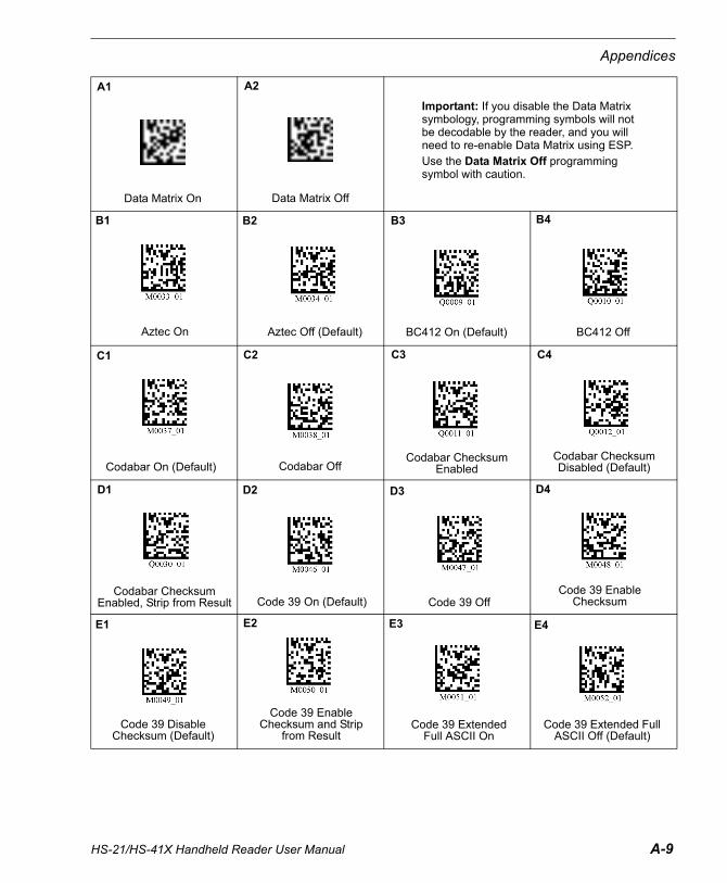
HS-21/HS-41X Handheld Reader User Manual A-9
Appendices
A1
Data Matrix On
A2
Data Matrix Off
Important: If you disable the Data Matrix symbology, programming symbols will not be decodable by the reader, and you will need to re-enable Data Matrix using ESP. Use the Data Matrix Off programming symbol with caution.
Aztec On
B1
Aztec Off (Default)
B2 B3
BC412 On (Default)
B4
BC412 Off
C1
Codabar On (Default)
C2
Codabar Off
C3
Codabar Checksum Enabled
C4
Codabar Checksum Disabled (Default)
D1
Codabar Checksum Enabled, Strip from Result
D2
Code 39 On (Default)
D3
Code 39 Off
D4
Code 39 Enable Checksum
E1
Code 39 Disable Checksum (Default)
E2
Code 39 Enable Checksum and Strip
from Result
E3
Code 39 Extended Full ASCII On
E4
Code 39 Extended Full ASCII Off (Default)

A-10 HS-21/HS-41X Handheld Reader User Manual
Configuration Symbols
A1
Code 93 On (Default)
A2
Code 93 Off
A3
Code 128 On (Default)
A4
Code 128 Off
B1
Composite On
B2
Composite Off (Default)
B3
Interleaved 2 of 5 On (Default)
B4
Interleaved 2 of 5 Off
C1
Interleaved 2 of 5 Two Digit Minimum
C2
Interleaved 2 of 5 Four Digit Minimum
C3
Interleaved 2 of 5 Six Digit Minimum
D1
Interleaved 2 of 5 Checksum Enabled
D2
Interleaved 2 of 5 Checksum Disabled (Default)
D3
Interleaved 2 of 5 Checksum Enabled,
Strip from Result
E4
Postal On
C4
Interleaved 2 of 5 with Control Character
Stripped
D4
MicroPDF417 On
E1
MicroPDF417 Off (Default)
E2
PDF417 On (Default)
E3
PDF417 Off

HS-21/HS-41X Handheld Reader User Manual A-11
Appendices
C2
EAN Status Enabled (Default)
C3
EAN Status Disabled
C4
UPC-E as UPC-A Enabled
D1
UPC-E as UPC-A Disabled (Default)
D2
Pharmacode On
A1
Postal Off (Default)
D3
Pharmacode Off (Default)
D4
Pharmacode Fixed Symbol Length Enabled
E1
Pharmacode Fixed Symbol Length Disabled
(Default)
E2
Pharmacode Bar Width Status Mixed (Default)
E3
Pharmacode Bar Width Status All Narrow
E4
Pharmacode Bar Width Status All Wide
A2
QR Code Off
A3
QR Code Inverse and Standard On
A4
QR Code and Micro QR Code On
B1
GS1 DataBar Limited On
B2
All GS1 DataBar On (Default)
B3
All GS1 DataBar Off
B4
UPC On (Default)
C1
UPC Off

A-12 HS-21/HS-41X Handheld Reader User Manual
Configuration Symbols
A1
Pharmacode Bar Width Status Fixed Threshold
A2
Pharmacode Direction Forward (Default)
A3
Pharmacode Direction Reverse
A4
Delete Scanned Data from Memory
B1
ID and Firmware Version
B2
Clear All JavaScript Rules
B3
Save Settings
B4
Disable Duplicate Symbol Timeout
C1
1 Second Duplicate Scan Delay
C2
2 Second Duplicate Scan Delay
C3
3 Second Duplicate Scan Delay
C4
Default Trigger Delay

HS-21/HS-41X Handheld Reader User Manual A-13
Appendices
Configuration Symbol ReferenceBeeperBeep Off ..............................................................................................................................A-7 (B3)Beep On ..............................................................................................................................A-7 (B4)
Continuous TriggerContinuous Trigger Off ........................................................................................................A-7 (C1)
Keyboard MappingU.S. Keyboard Mapping (Default)........................................................................................A-8 (C3)U.S. Keyboard Mapping without Leading 0 .........................................................................A-8 (C4)U.S. Keyboard with Ctr+Char ..............................................................................................A-8 (D1)French Keyboard Mapping ..................................................................................................A-8 (D2)German Keyboard Mapping ................................................................................................A-8 (D3)Japanese Keyboard Mapping..............................................................................................A-8 (D4)Universal Keyboard Mapping...............................................................................................A-8 (E1)Custom Keyboard................................................................................................................A-8 (E2)Belgian Keyboard ................................................................................................................A-8 (E3)Swiss Keyboard...................................................................................................................A-8 (E4)
Motion DetectionMotion Detect Off.................................................................................................................A-7 (C2)Motion Detect On, Start Delay 0..........................................................................................A-7 (C3)Motion Detect On, Start Delay 500 ms ................................................................................A-7 (C4)
Preamble/Postamble SettingsPreamble - Comma..............................................................................................................A-7 (D3)Preamble - Space................................................................................................................A-7 (D4)Preamble - Tab (Keyboard Only).........................................................................................A-7 (E1)Preamble - Tab (Serial Only) ...............................................................................................A-7 (E2)Preamble - Erase (None).....................................................................................................A-7 (E3)Preamble - CR LF (Serial Only)...........................................................................................A-7 (E4)Postamble - CR (Serial Only) ..............................................................................................A-8 (A1)Postamble - Comma............................................................................................................A-8 (A2)Postamble - LF (Serial Only) ...............................................................................................A-8 (A3)Postamble - CR LF (Serial Only) .........................................................................................A-8 (A4)Postamble - Space ..............................................................................................................A-8 (B1)Postamble - Enter (Keyboard Only).....................................................................................A-8 (B2)Postamble - Tab (Keyboard Only) .......................................................................................A-8 (B3)Postamble - Tab (Serial Only) .............................................................................................A-8 (B4)Postamble - Erase (None) ...................................................................................................A-8 (C1)Preamble and Postamble - Erase........................................................................................A-8 (C2)
Reader Text CommandsReader Text Commands On................................................................................................A-7 (D1)Reader Text Commands Off................................................................................................A-7 (D2)

A-14 HS-21/HS-41X Handheld Reader User Manual
Configuration Symbols
RS-232 SettingsReset to RS-232 Defaults.................................................................................................... A-6 (B3)RS-232 7 Data Bits.............................................................................................................. A-6 (B4)RS-232 8 Data Bits (Default) ...............................................................................................A-6 (C1)RS-232 1200 Baud..............................................................................................................A-6 (C2)RS-232 2400 Baud..............................................................................................................A-6 (C3)RS-232 4800 Baud..............................................................................................................A-6 (C4)RS-232 9600 Baud..............................................................................................................A-6 (D1)RS-232 19200 Baud............................................................................................................A-6 (D2)RS-232 38400 Baud............................................................................................................A-6 (D3)RS-232 57600 Baud............................................................................................................A-6 (D4)RS-232 115200 Baud (Default) ........................................................................................... A-6 (E1)RS-232 Even Parity .............................................................................................................A-6 (E2)RS-232 Odd Parity ..............................................................................................................A-6 (E3)RS-232 No Parity (Default).................................................................................................. A-6 (E4)UART Flow Control None (Default) ..................................................................................... A-7 (A1)UART Flow Control Hardware............................................................................................. A-7 (A2)RS-232 Raw Mode (Default) ............................................................................................... A-7 (A3)RS-232 Packet Mode .......................................................................................................... A-7 (A4)
SymbologiesData Matrix On .................................................................................................................... A-9 (A1)Data Matrix Off .................................................................................................................... A-9 (A2)Aztec On.............................................................................................................................. A-9 (B1)Aztec Off (Default) ............................................................................................................... A-9 (B2)BC412 On (Default) .............................................................................................................A-9 (B3)BC412 Off............................................................................................................................ A-9 (B4)Codabar On (Default) ..........................................................................................................A-9 (C1)Codabar Off .........................................................................................................................A-9 (C2)Codabar Checksum Enabled...............................................................................................A-9 (C3)Codabar Checksum Disabled (Default) ...............................................................................A-9 (C4)Codabar Checksum Enabled and Strip from Result............................................................A-9 (D1)Code 39 On (Default) ..........................................................................................................A-9 (D2)Code 39 Off .........................................................................................................................A-9 (D3)Code 39 Enable Checksum.................................................................................................A-9 (D4)Code 39 Disable Checksum (Default) ................................................................................. A-9 (E1)Code 39 Enable Checksum and Strip from Result .............................................................. A-9 (E2)Code 39 Extended Full ASCII On........................................................................................A-9 (E3)Code 39 Extended Full ASCII Off (Default) ......................................................................... A-9 (E4)Code 93 On (Default) ........................................................................................................ A-10 (A1)Code 93 Off ....................................................................................................................... A-10 (A2)Code 128 On (Default) ...................................................................................................... A-10 (A3)Code 128 Off .....................................................................................................................A-10 (A4)Composite On.................................................................................................................... A-10 (B1)

HS-21/HS-41X Handheld Reader User Manual A-15
Appendices
Composite Off (Default) .....................................................................................................A-10 (B2)Interleaved 2 of 5 On (Default) ..........................................................................................A-10 (B3)Interleaved 2 of 5 Off .........................................................................................................A-10 (B4)Interleaved 2 of 5 Two Digit Minimum ...............................................................................A-10 (C1)Interleaved 2 of 5 Four Digit Minimum...............................................................................A-10 (C2)Interleaved 2 of 5 Six Digit Minimum .................................................................................A-10 (C3)Interleaved 2 of 5 with Control Character Stripped............................................................A-10 (C4)Interleaved 2 of 5 Checksum Enabled...............................................................................A-10 (D1)Interleaved 2 of 5 Checksum Disabled (Default) ...............................................................A-10 (D2)Interleaved 2 of 5 Checksum Enabled and Strip from Result ............................................A-10 (D3)MicroPDF417 On...............................................................................................................A-10 (D4)MicroPDF417 Off (Default) ................................................................................................A-10 (E1)PDF417 On (Default) .........................................................................................................A-10 (E2)PDF417 Off........................................................................................................................A-10 (E3)Postal On...........................................................................................................................A-10 (E4)Postal Off (Default) ............................................................................................................A-11 (A1)QR Code Off ......................................................................................................................A-11 (A2)QR Code Inverse and Standard On ..................................................................................A-11 (A3)QR Code and Micro QR Code On .....................................................................................A-11 (A4)GS1 DataBar Limited On...................................................................................................A-11 (B1)All GS1 DataBar On (Default)............................................................................................A-11 (B2)All GS1 DataBar Off ..........................................................................................................A-11 (B3)UPC On (Default) ..............................................................................................................A-11 (B4)UPC Off .............................................................................................................................A-11 (C1)EAN Status Enabled (Default) ...........................................................................................A-11 (C2)EAN Status Disabled .........................................................................................................A-11 (C3)UPC-E as UPC-A Enabled ................................................................................................A-11 (C4)UPC-E as UPC-A Disabled (Default).................................................................................A-11 (D1)Pharmacode On ................................................................................................................A-11 (D2)Pharmacode Off (Default)..................................................................................................A-11 (D3)Pharmacode Fixed Symbol Length Enabled .....................................................................A-11 (D4)Pharmacode Fixed Symbol Length Disabled (Default)......................................................A-11 (E1)Pharmacode Bar Width Status Mixed (Default) .................................................................A-11 (E2)Pharmacode Bar Width Status All Narrow.........................................................................A-11 (E3)Pharmacode Bar Width Status All Wide ............................................................................A-11 (E4)Pharmacode Bar Width Status Fixed Threshold................................................................A-12 (A1)Pharmacode Direction Forward (Default) ..........................................................................A-12 (A2)Pharmacode Direction Reverse.........................................................................................A-12 (A3)
TargetingTargeting Off........................................................................................................................A-7 (B1)Targeting On........................................................................................................................A-7 (B2)

A-16 HS-21/HS-41X Handheld Reader User Manual
Configuration Symbols
USB SettingsDefault to USB (HID) ...........................................................................................................A-6 (A1)USB Keyboard (Windows)................................................................................................... A-6 (A2)USB Native (HID) Mode ......................................................................................................A-6 (A3)USB Virtual COM Mode....................................................................................................... A-6 (A4)USB Enable Alternate OS (Mac, Linux, CE)........................................................................ A-6 (B1)USB Disable Alternate OS................................................................................................... A-6 (B2)
Other CommandsDelete Scanned Data from Memory .................................................................................. A-12 (A4)ID and Firmware Version................................................................................................... A-12 (B1)Clear All JavaScript Rules................................................................................................. A-12 (B2)Save Settings .................................................................................................................... A-12 (B3)Disable Duplicate Symbol Timeout.................................................................................... A-12 (B4)1 Second Duplicate Scan Delay........................................................................................A-12 (C1)2 Second Duplicate Scan Delay........................................................................................A-12 (C2)3 Second Duplicate Scan Delay........................................................................................A-12 (C3)Default Trigger Delay.........................................................................................................A-12 (C4)

HS-21/HS-41X Handheld Reader User Manual A-17
Appendices
Appendix D — Serial Commands
Text CommandsText commands may be sent to the reader in RS-232 or USB Virtual COM mode using any serial communications software, e.g., ESP Terminal.
Encoded-data is decoded by the reader by replacing %xx by a single byte with the value specified by the two hex-digits xx, e.g., %25 would be replaced by character number 0x25, which is ASCII ‘%’.
text-command: command-type encoded-dataopt carriage-return
command-type: Single ASCII character in the set defined in Command Types.
encoded-data: encoded-datum / encoded-data encoded-datum
encoded-datum: printable-character | % hex-digit hex-digit
printable-character: any byte value in the range [0x20,0x7e]
hex-digit: ‘0’ | ‘1’ | ‘2’ | ‘3’ | ‘4’ | ‘5’ | ‘6’ | ‘7’ | ‘8’ | ‘9’ |‘A’ | ‘B’ | ‘C’ | ‘D’ | ‘E’ | ‘F’
| ‘a’ | ‘b’ | ‘c’ | ‘d’ | ‘e’ | ‘f’
carriage-return: 0x0d
In order to eliminate inadvertent commanding of the reader, Text Commands are disabled by default. To enable Text Commands requires an initial sequence: ;>PAx where x is as defined in the Reader Settings Table, register setting 41. (Note: ‘A’ is the ASCII character that corresponds to 41 HEX.)
For example, to send the reader commands by typing commands in ESP Terminal:
;>PA1
P(xx)yy
P(xx)yy
~
PA8
Where ;>PA1 enables text commands with echo and command responses; P%xxyy can be any desired commands; ~ saves the settings just sent (the ~ command saves all but communication-related settings); and PA8 turns text commands back off (except for the initial sequence). (Note: ‘A’ is the ASCII character that corresponds to 41 hex, thus P%418 would be equivalent.)
Note: ;>PA1 is used for interactive text commands. If the commands are to be saved in a file and sent non-interactively, use ;>PA7 instead; this enables text commands but disables echo and command responses. (See Command Types, Reader Settings, and CRB System for additional information.)
The following two examples can be sent to a reader in RS-232 mode from ESP Terminal by just typing the example text.

A-18 HS-21/HS-41X Handheld Reader User Manual
Serial Commands
Example 1 (make the reader beep 3 times):
#%03 Expected output: should make reader beep 3 times
Example 2 (set reader to continuous read, High Density field (FOI0) only):
P(C4)5 Expected output: should set reader to continuous read, High Density field (FOI0) only
Example 3 (set reader to trigger read mode):
P(C4)255 Expected output: should set reader to trigger read
Packetized CommandsPacketized commands consist of packetized data sent from Host-to-Reader to configure and cause the reader to perform certain functionalities (e.g. settings). Packetized commands are always enabled, unlike text commands. In addition, they include error detection data, making them more robust than text commands.
normal-command structure:
[preamble] [command-type] [data-size] [dataopt] [reserved field] [crc14]
preamble: 0xEE 0xEE 0xEE 0xEE
command-type: Single ASCII character in the set defined in Command Types.
data-size: byte value in range [0,240], which indicates size of data (in bytes) following this before [reserved field]
dataopt: datum or data datum
data or datum is any byte value in the range [0,255]
reserved field: 0x00
crc14: Two consecutive bytes, each in range [0,127], representing the crc16 value and with the value 0x7F7F, most significant byte first. The packet crc16 is calculated over the entire packet, excluding the preamble and the crc14 itself. (See source files crc16.[hc] (Appendix) for details on the crc16 algorithm and polynomials to be used.)
Note: Most terminal programs will omit or not transmit a NULL (0x00) character entered in the terminal. So, if one tries to compose the command structure manually and send it through a terminal program, one might have to send everything before the reserved field, then send the 0x00 (key Ctrl+@ in ESP terminal view) by itself, and then the CRC14 checksum bytes.
In the first of the examples shown below, for instance, “0xEE 0xEE 0xEE 0xEE 0x23 0x01 0x03” can be sent using ESP’s Terminal, then the NULL character can be sent by typing “Ctrl + Shift + 2”, and then “0x4E 0x71” can be sent to complete the command sequence.
Examples:
0xEE 0xEE 0xEE 0xEE 0x23 0x01 0x03 0x00 0x4E 0x71
This executes the beep command, causing the reader to beep 3 times. “#%03” in text command format. The first 4 0xEE are the preamble, followed by the ‘#’ character or 23h the beep command, and followed by data size of 1 with a data datum of 3 following it. 0x00 is the reserved field followed by two bytes CRC14 of the command + data size + data datum.

HS-21/HS-41X Handheld Reader User Manual A-19
Appendices
0xEE 0xEE 0xEE 0xEE 0x49 0x00 0x00 0x03 0x3C
This executes the info command, “I” in text command format. Since it does not have any data datum associated with it, 0x00 following 0x49 (ASCII “I”) but before the reserved field and CRC14 (0x00 0x03 0x3C) indicating it has no dataopt.
0xEE 0xEE 0xEE 0xEE 0x50 0x04 0xC4 0x32 0x35 0x35 0x00 0x43 0x3C
This will change the reader to trigger-read mode, “P(C4)255” in text command format. 0x50 is the command-type, 0x04 indicates that following 4 bytes are the data option with 0xC4 being the register that needs to be updated and 0x32 0x32 0x35 being the new value.
0xEE 0xEE 0xEE 0xEE 0x50 0x03 0xA9 0x35 0x63 0x00 0x77 0x6B
This will change the reader Bypass Gain to 92 (0x5c) percent, “P(A9)5c” in text command format. 0x50 is the command-type, 0x03 indicates that the following 3 bytes are the data option with 0xA9 being the register that needs to be updated and 0x35 0x63 (5c) being the new value.
0xEE 0xEE 0xEE 0xEE 0x50 0x07 0x28 0x31 0x45 0x41 0x29 0x46 0x41 0x00 0x14 0x18
This will change Good Read Duration to 250ms, “P(1EA)FA” in text command format. In this case the register 1EA is more than one byte can hold; the register is converted to its individual ASCII hex value bounded by 0x28 and 0x29, underlined above.

A-20 HS-21/HS-41X Handheld Reader User Manual
Serial Commands
Command Types
#
Causes the reader to beep the specified number of times; data contains the number as a single character in the range [0,127].
(The reader will respond with d or e.)
Example – beep three times: #%03
$Posts an event to the reader; data contains the event number as a single character. See setting 39 in Reader Settings for a list of the event numbers.
(The reader will respond with d or e.)
(
Causes the reader to upload any logged error messages (no data)
(The reader will respond with a g packet, zero or more z packets, and a final d or e. Each z packet contains a portion of the requested data in its data field.
Note: This is very similar to the response to the X command; however, p packets are not applicable and the g and d/e packets are not sup-pressed even in raw mode.)
)Causes the reader to erase its log of error messages (no data)
(The reader will respond with d or e.)
,
Causes the reader to send a list of current reader settings (no data)
(The reader will respond with d containing a space-separated list of all setting values (in order, expressed as hexadecimal ASCII characters) or with e.)
/
Toggle a bit (or bits) in a reader setting; data contains a printable ASCII string in the following format: hexadecimal setting number in parenthe-ses followed by a 32-bit signed integer value, expressed in ASCII hexa-decimal characters (with optional minus sign) or ASCII decimal characters preceded by the ‘#’ character, e.g., /(2e)1000 or /(2e)#4096; the specified integer is XOR’ed with the existing setting value.
(The reader will respond with d or e.)
Note: See Reader Settings for possible reader settings.
1
Indicates the start of a file download; data is empty. This command is followed by a sequence of 2 commands containing the file data and a download-end command (e.g., 5).
(The reader will respond with d or e.)
2Indicates a continuation of a file download; data contains the next por-tion of the file data.
(The reader will not send any response.)
5
Indicates the end of a regular file download; data contains the name of the file, which is from 1 to 200 letters, digits, periods, hyphens, and underscores, terminated with ASCII NUL.
(The reader will respond with d, e, or f.)

HS-21/HS-41X Handheld Reader User Manual A-21
Appendices
9 Requests the reader to delete a file from its storage; data contains the file name, terminated with ASCII NUL.
; Reserved (nop – treated as a comment)
<Causes the reader to send a list of saved reader settings (no data)
(see ‘,’ command)
=
Puts setting directly to reader’s non-volatile memory so that it will take effect upon next reboot; data is as defined in the / command; the speci-fied integer replaces the existing setting value.
Note: This command can be used to set communication modes without losing communication during the process.
(The reader will respond with d or e.)
>
Causes the reader to send a string of text to the host as a z packet;
data contains the text to send.
(The reader will respond with a z packet containing the text.)
@
Causes the reader to reset its internal date/timestamp to the specified time; data contains the date and/or time in one of the following formats.
yyyy-mm-dd hh:mm:ss
yyyy-mm-dd hh:mm
hh:mm:ss
hh:mm
Note: The separators are optional; only digits are significant.
(The reader will respond with d or e.)
Examples:
Set to midnight: @00:00
Set to Sept 1, 2005 11:52:02 PM: @2005-09-01 23:52:02
Note: On units without a battery-backed real-time clock, the date and time will reset to 2000-01-01 00:00:00 upon power-up.)
A
Notifies the reader that the previously sent data were rejected for one of the following reasons:
• The packet was encrypted and the decryption failed.
• The host is locked to a different reader.
The reader should indicate to the user that the packet has been rejected; e.g., it may sound error beeps. See related setting 0x12f, notify-of-packet-rejection.
(The reader will not respond to the host.)
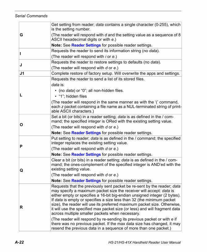
A-22 HS-21/HS-41X Handheld Reader User Manual
Serial Commands
G
Get setting from reader; data contains a single character (0-255), which is the setting number.
(The reader will respond with d and the setting value as a sequence of 8 ASCII hexadecimal digits or with e.)
Note: See Reader Settings for possible reader settings.
IRequests the reader to send its information string (no data).
(The reader will respond with i or e.)
JRequests the reader to restore settings to defaults (no data).
(The reader will respond with d or e.)J1 Complete restore of factory setup. Will overwrite the apps and settings.
L
Requests the reader to send a list of its stored files.
data is:
• (no data) or “0”; all non-hidden files.
• “1”; hidden files
(The reader will respond in the same manner as with the ‘(’ command, each z packet containing a file name as a NUL-terminated string of print-able ASCII characters.)
O
Set a bit (or bits) in a reader setting; data is as defined in the / com-mand; the specified integer is ORed with the existing setting value.
(The reader will respond with d or e.)
Note: See Reader Settings for possible reader settings.
P
Put setting to reader; data is as defined in the / command; the specified integer replaces the existing setting value.
(The reader will respond with d or e.)
Note: See Reader Settings for possible reader settings.
Q
Clear a bit (or bits) in a reader setting; data is as defined in the / com-mand; the ones-complement of the specified integer is AND’ed with the existing setting value.
(The reader will respond with d or e.)
Note: See Reader Settings for possible reader settings.
R
Requests that the previously sent packet be re-sent by the reader; data may specify a maximum packet size the receiver will accept: data is either empty or specifies a 16-bit big-endian unsigned integer (2 bytes). If data is empty or specifies a size less than 32 (the minimum packet size), the reader will use its preferred maximum packet size. Otherwise, it will use the specified max packet size (or less) and will fragment data across multiple smaller packets when necessary.
(The reader will respond by re-sending its previous packet or with e if there was no previous packet. If the max data size has changed, it may resend the previous data in a sequence of more than one packet.)

HS-21/HS-41X Handheld Reader User Manual A-23
Appendices
T
Requests the current date and time (no data).
(The reader will respond with d with data containing the date and time formatted as yyyy-mm-dd hh:mm:ss.)
Note: On units without a battery-backed real-time clock, the date and time will reset to 2000-01-01 00:00:00 upon power-up.
U Reserved for script engine.
WRequests the reader to write its current settings from RAM to its non-vol-atile memory.
(The reader will respond with d or e.)
YAcknowledge the receipt of a packet; data specifies the received packet number (one byte).
(The reader will not respond.)
Z
Request the reader to reboot.
data is:
• empty or ‘0’; reboot the reader.
• ‘1’; restart application.
(The reader will respond with d or e before it reboots.)
^
Requests the reader to upload the specified stored file; data contains the file name, terminated with ASCII NUL.
The reader will respond with:
• ‘g’ packet containing “filename<tab>(size)”
• ‘z’ packet(s)
• ‘d’ packet containing “EOF<tab>(CRC16)”
Note: filename “help” is reserved to send command information.
_Causes the reader to wait for all buttons to be released and clear its event queue.
(The reader will respond with d or e.)
|Process data as a decoded string.
(The reader will respond with d or e.)

A-24 HS-21/HS-41X Handheld Reader User Manual
Serial Commands
Simple ProtocolThe file is split into blocks of 236 or less bytes each and downloaded to the reader via 1, 2, and 5 commands using the following sequence:
1. Send a 1 command to initialize the download.2. Wait for a d or e response from the reader or a timeout.
a. If timeout or e response, restart the sequence at step 1.b. If d response, continue to step 3.
3. Send a series of 2 commands, each with a portion of the file. (The reader will not send any response.)
4. Send a 5 command to end the download and install the file.5. Wait for a d, e, or f response from the reader or a timeout.
a. If f response or timeout, restart the sequence at step 1.b. If e response, repeat step 5.c. If d response, file download has completed successfully.
Note: The timeout will need to be increased from the normal response timeout to allow the firmware time to write the file to the flash memory.

HS-21/HS-41X Handheld Reader User Manual A-25
Appendices
Reader SettingsThe host sets the reader settings using the /, O, P, Q, and = commands and reads them using the G, ,, and < commands.
For example, the following P command sets register 2C to the value C8.
P(2C)C8
Note: For two-digit setting numbers (i.e., settings 00 through fd), an alternative format may be used: in place of the parentheses and hexadecimal setting number, substitute a single character, which represents the setting number. The equivalent to the example above is P,C8 (the ASCII ‘,’ character has the hexadecimal value 2c). (In certain circumstances, such as with text commands, “percent-encoding” may be used for encoding a character as a sequence consisting of the percent character followed by two hexadecimal digits. With percent-encoding, the example may be expressed as P%2CC8.)
In the Reader Settings Table, the Reg column is the setting number, in hexadecimal, to be used with the commands identified above. In the Default column, all values are in hexadecimal unless otherwise specified. To use decimal values in commands you must precede the data with a pound sign ‘#’. The following P command sets register 2C to the same value as the example above:
P(2C)#200
Since the single digit values of 0 through 9 are identical in decimal and hexadecimal, no indicator is needed.

A-26 HS-21/HS-41X Handheld Reader User Manual
Serial Commands
Binary Dip SwitchSome registers are what Microscan terms a ‘Binary Dip Switch’ where the value of each bit of the data string switches on or off some part of the behavior of that register. The bits are numbered from least significant to most (right to left). Each bit can be on or off (1 or 0).
An example of this is register 0B, ‘Codabar Checksum’. The following settings are possible:
Given the settings above, the binary string turns Codabar Checksum ON and strips it from output.
Thus, the command to implement the settings above would be:
P(48)3
or
P(48)#03
Field of InterestThe reader optics are typically split into two separate fields - Field Of Interest 0 (FOI0) and Field Of Interest 1 (FOI1). In certain circumstances, these fields can be customized to the requirements of the user. In the default configuration of these fields FOI0 is the High Density (HD) field and FOI1 is the Wide (W) field.
At a given focus distance, the HD field is designed to read small, low-mil symbols while the Wide field is designed to pick up large, wide symbols.
This document will refer to FOI0 as HD and FOI1 as Wide.
Bit (R to L) Controls Value
0 Codabar Checksum Checking0: Disabled 1: Enabled
1 Strip Checksum from Output0: Disabled 1: Enabled

HS-21/HS-41X Handheld Reader User Manual A-27
Appendices
Reader Settings Table
Reg Setting Name Default (Hex) Comment
04 Continuous Illumination During Read 0
0: Minimal Illumination1: Leave Illumination On Until End Read Cycle
Leave illumination on during read.
08 Reader Packet Format 1
1: Raw2: Packet Mode Version 1For example, USB “two-way” native:
1B: 5 (USB Native)08: 2 (packet mode)42: 1 (expect response)
Also see registers: 1B, 42
0A NEC 2 of 5 Symbology
1 Binary Dip Switch
Note: All symbol lengths greater than 2 are always enabled when NEC 2 of 5 Decoding is enabled.
Bit Controls Value
0 NEC 2 of 5 Decoding
0: Disabled1: Enabled
1 Checksum checking
0: Disabled1: Enabled
2 Strip checksum from result
0: Disabled1: Enabled
3 1 Digit Symbol Allowed
0: Disabled1: Enabled
4 2 Digit Symbol Allowed
0: Disabled1: Enabled

A-28 HS-21/HS-41X Handheld Reader User Manual
Serial Commands
0B Matrix 2 of 5 Symbology 1
Binary Dip Switch
Note: All symbol lengths greater than 2 are always enabled when Matrix 2 of 5 Decoding is enabled.
0C Telepen Symbology 10: Disabled1: Enabled
0D Enable Non-Square Data Matrix Sym-bology
00: Disabled1: Enabled
0F Targeting Control 10: Targeting Disabled1: Targeting Enabled
16 Data Matrix Rectangular Symbology 00: Disabled1: Enabled
19 Data Matrix Symbology 1
Binary Dip Switch
Bit Controls Value
0 Matrix 2 of 5 Decoding
0: Disabled1: Enabled
1 Checksum checking
0: Disabled1: Enabled
2 Strip checksum from result
0: Disabled1: Enabled
3 1 Digit Symbol Allowed
0: Disabled1: Enabled
4 2 Digit Symbol Allowed
0: Disabled1: Enabled
Bit Controls Value
0 Data Matrix Decoding
0: Disabled1: Enabled
1 Inverse Data Matrix Decoding
0: Disabled1: Enabled

HS-21/HS-41X Handheld Reader User Manual A-29
Appendices
1B Communications Mode 8
1: RS232 serial2: USB keyboard5: USB Native (HID)6: USB VComm8: Dynamic (1 if decode is RS232; 2 if decode is USB)This setting is used in conjunction with settings 08 and 42 to configure the communication mode between stan-dard “one-way” and “two-way” modes. For example, USB “two-way” native:
1b: 5 (USB Native)08: 2 (packet mode)42: 1 (expect response)
Note: The following must be completed within 1 second.first output report with numlock set and capslock clearsecond output report with numlock set and capslock clearthird output report with capslock set numlock clearfourth output report with capslock set numlock clearfifth output report with numlock set and capslock clearsixth output report with numlock set and capslock clearOn the last output report comm proto-col is set to raw mode, comm expect response is false and comm mode is USB Downloader mode.Also see registers: 08, 42
1C Serial Baud Rate 1C200 (#115200)
All standard baud rates up #115200• #9600 (2580)• #19200 (4B00)• #38400 (9600)• #57600 (E100)• #115200 (1C200)
1D Serial Stop Bits 11: One2: Two
1E Serial Data Bits 87: Seven8: Eight

A-30 HS-21/HS-41X Handheld Reader User Manual
Serial Commands
22 Serial Parity 00: None1: Odd2: Even
26 Beep Volume (percent) 64 (#100)
Valid Range: 0 to 64 (#100) PercentThis is the current percentage of full volume potential.Also see registers: 59, A7
29 PDF417 Symbology 10: Disabled 1: EnabledAlso see registers: 2A, CF
2A MicroPDF417 Symbology 00: Disabled 1: EnabledAlso see registers: 29, CF
2B QR Code Symbology 1
Binary Dip Switch
Bit Controls Value
0 QR Code Decod-ing
0: Disabled1: Enabled
1 Inverse QR Code Decoding
0: Disabled1: Enabled
2 Micro QR Code Decoding
0: Disabled1: Enabled
3 Inverse Micro QR Code Decoding
0: Disabled1: Enabled

HS-21/HS-41X Handheld Reader User Manual A-31
Appendices
2C Idle Mode Countdown Timer (ms) 64 (#100)
Valid Range: 0 to 7FFFFFFF Millisec-ondsCounts down to the change to Idle Mode.The most significant bit (MSB) of the 32-bit register indicates whether this timer is enabled. Enable or Disable the timer by setting the MSB.You can change the big directly by set-ting the register value (such as setting to #100) or you can change the value of just the MSB using the O (set), Q (clear) or / (toggle) bit commands. See Command Types for more information on these commands.
Idle Mode is the time between the last user interaction with the reader (button press, etc.) or firmware interaction (communications, etc.) and Standby Mode. There are many user and firm-ware events that will reset the timer. Therefore, it may seem that the timer is longer than the value set.This state: Active (highest power usage)Next state: Idle
2D Keyboard Maps 0
0: US English (without leading 0 in the ALT _ Number)1: ASCII (ALT+number) - universal2: Custom (requires user to download keyboard map)3: US English (with leading 0 in the ALT + number for non-printable ASCII)4: French Keyboard5: German Keyboard6: Japanese Keyboard7: US English (with CTRL + char for non-printable ASCII)
Action CommandEnable O(32)#-2147483648Disable Q(32)#-2147483648Toggle /(32)#-2147483648

A-32 HS-21/HS-41X Handheld Reader User Manual
Serial Commands
34 Maximum Candidate Decodes Per Read 1
The Reader will process up to this number of codes per “read code” event. If there are more than this many codes in the field of view and within tar-get tolerance, only the first ones will be decoded. For fastest performance with single codes, set to 1.
35 Button Stay-Down Time (ms) 0
Valid Range: 0 to 7FFFFFFF Millisec-ondsKeep processing the “read code” events for this amount of time (act as if the button stays down for this time)
36 Number of Control Frames Before Pic-ture Capture
0
Valid Range: 0 to 7FFFFFFF FramesNumber of frames captured and dis-carded before live picture to give the gain control time to adjust.Also see registers: 43, AC, AD, AE, AF
39 Trigger 1 3
The specified event is posted upon press of this button. The events are defined below:0: No Action1: Keep Awake2: Show Target3: Read In Both Fields (Default)4: Default Event Selected By Hardware 5: Read In High Density field (FOI0). 6: Read In Wide field (FOI1). 7: Take Picture8: Read In Most Recently Successful Field255: Idle
40 Text Command Timeout (ms) 2AF8 (#11000)
Valid Range: 0 to 7FFFFFFF Millisec-onds The maximum time during which a complete text command from Host must be received. (Pending text com-mand data is discarded when the time-out is exceeded.)
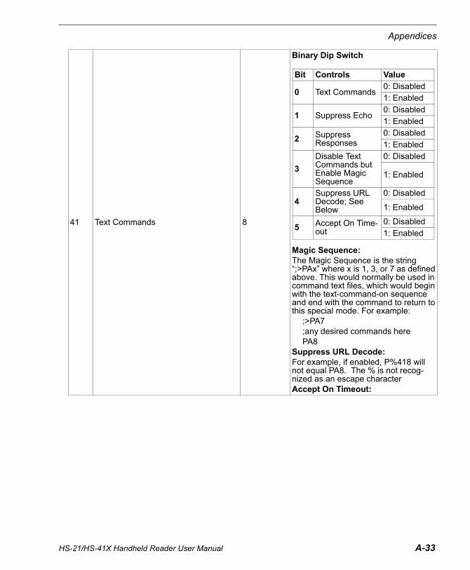
HS-21/HS-41X Handheld Reader User Manual A-33
Appendices
41 Text Commands 8
Binary Dip Switch
Magic Sequence:The Magic Sequence is the string “;>PAx” where x is 1, 3, or 7 as defined above. This would normally be used in command text files, which would begin with the text-command-on sequence and end with the command to return to this special mode. For example:
;>PA7 ;any desired commands herePA8
Suppress URL Decode: For example, if enabled, P%418 will not equal PA8. The % is not recog-nized as an escape character Accept On Timeout:
Bit Controls Value
0 Text Commands0: Disabled1: Enabled
1 Suppress Echo0: Disabled1: Enabled
2 Suppress Responses
0: Disabled1: Enabled
3
Disable Text Commands but Enable Magic Sequence
0: Disabled
1: Enabled
4Suppress URL Decode; See Below
0: Disabled
1: Enabled
5 Accept On Time-out
0: Disabled1: Enabled

A-34 HS-21/HS-41X Handheld Reader User Manual
Serial Commands
42 Expect Acknowledgement From Host 0
0: Reader doesn’t wait for acknowl-edge1: Reader will retransmit data when Host doesn’t acknowledge receiptThis setting is used in conjunction with settings 1B and 42 to configure the communication mode between stan-dard “one-way” and “two-way” modes. For example, USB “two-way” native:
1B: 5 (USB Native)08: 2 (packet mode)42: 1 (expect response)
Also see registers: 08, 1B
43 JPEG Picture Quality (percent) 32 (#50)
Valid Range: 0 to 64 (#100) Percent0: Raw Image (No JPEG Compression)1 To 100: JPEG Compression Quality PercentAlso see registers: 36, AC, AD, AE, AF
45 Read Cycle Timeout 1F4 (#500) Valid Range: 0 to FFFF (#65535) ms
47 Maxicode Symbology 0
Binary Dip Switch
48 Codabar Checksum 0
Binary Dip Switch
Bit Controls Value
0 Codabar Checksum Checking
0: Disabled1: Enabled
1 Strip Checksum from Output
0: Disabled1: Enabled
Bit Controls Value
0 Maxicode Decoding, Mode 0
0: Disabled1: Enabled
1 Maxicode Decoding, Mode 1
0: Disabled1: Enabled
2 Maxicode Decoding, Mode 2
0: Disabled1: Enabled
3 Maxicode Decoding, Mode 3
0: Disabled1: Enabled
4 Maxicode Decoding, Mode 4
0: Disabled1: Enabled
5 Maxicode Decoding, Mode 5
0: Disabled1: Enabled
6 Maxicode Decoding, Mode 6
0: Disabled1: Enabled

HS-21/HS-41X Handheld Reader User Manual A-35
Appendices
49 Code 39 Symbology 00: Disabled1: EnabledCode 39 Full ASCII Decoding
4A Composite Codes 0
0: Disabled1: EnabledComposite Code DecodingAlso see register: D8
4B Postal Code Symbology 00: Disabled1: Enabled
4C GS1 Symbology 1F (#31)
Binary Dip Switch
4D UPC Expansion 00: Disabled1: EnabledAlso see registers: 4E, 6A, 74
4E UPC Supplemental 00: Disabled1: EnabledAlso see registers: 4D, 6A, 74
Bit Controls Value
0 GS1 Expanded decoding
0: Disabled1: Enabled
1 GS1 Expanded Stacked decoding
0: Disabled1: Enabled
2 GS1 Limited decod-ing
0: Disabled1: Enabled
3 GS1-14 and GS1-14 Truncated decoding
0: Disabled1: Enabled
4
GS1-14 Stacked and GS1-14 Stacked Omnidirectional decoding
0: Disabled
1: Enabled

A-36 HS-21/HS-41X Handheld Reader User Manual
Serial Commands
4F MSI Plessey Symbology 1
Binary Dip Switch
50 Aztec Symbology 1
Binary Dip Switch
53 Decoder HD field (FOI0) Width 280 (#640)
Valid Range: 1 to 640 pixels Decoder uses only the specified pixel width in the HD field (FOI0).Also see registers: 54, 98, 99
54 Decoder HD field (FOI0) Height 3C0 (#960)
Valid Range: 1 to 960 pixels Decoder uses only the specified pixel height in the HD field (FOI0).Also see registers: 53, 98, 99
55 Notify Of Read Failure 0
0: Disabled1: Send “r” packet on no-read (See “r” packet in Packet Data.)0x100xx: post event on no-read, where the lower 8 bits specify the event num-ber. For example, 0x10009 to post Event 0x09.
Bit Controls Value
0 Aztec decoding0: Disabled1: Enabled
1 Inverse Aztec decod-ing
0: Disabled1: Enabled
Bit Controls Value
0 MSI Plessey0: Disabled1: Enabled
[3:1] Checksum
0: Disabled1: Enabled1: 1 mod 102: mod 10 and mod 113: 2 mod 105: 1 mod 10 strip cs6: mod 10 and mod 11 strip cs7: 2 mod 10 strip cs
4 Improved Bounds0: Disabled1: Enabled

HS-21/HS-41X Handheld Reader User Manual A-37
Appendices
59 Beep Duration 64 (#100)Valid Range: 0 to 7FFFFFFF Millisec-ondsAlso see registers: 26, A7
66 Bypass Illumination 0 Valid Range: 0 to 64 (#100) percent
6A UPC Symbology 10: Disabled1: EnabledAlso see registers: 4D, 4E, 74
6B Code 39 Symbology 10: Disabled1: EnabledAlso see register: 70
6C Code 93 Symbology 10: Disabled1: Enabled
6D Code 128 Symbology 10: Disabled1: Enabled
6E Interleaved 2 Of 5 Symbology 10: Disabled1: Enabled Also see registers: 71, C9
6F Codabar Symbology 10: Disabled1: Enabled
70 Code 39 Checksum 0
Binary Dip Switch
Also see register: 6B
71 Interleaved 2 Of 5 Checksum 0
Binary Dip Switch
Also see register: 6E, C9
74 UPC Short Margin 10: Disabled1: EnabledAlso see registers: 4D, 4E, 6A
78 Settings Lock 11: Settings unlocked3: Settings locked (except settings Lock)
Bit Controls Value
0 Interleaved 2 of 5 Checksum Checking
0: Disabled1: Enabled
1 Strip Checksum from Output
0: Disabled1: Enabled
Bit Controls Value
0 Code 39 Checksum Checking
0: Disabled1: Enabled
1 Strip Checksum from Output
0: Disabled1: Enabled
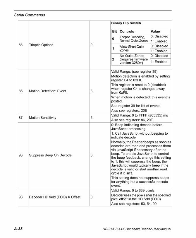
A-38 HS-21/HS-41X Handheld Reader User Manual
Serial Commands
85 Trioptic Options 0
Binary Dip Switch
86 Motion Detection: Event 3
Valid Range: (see register 39)Motion detection is enabled by setting register C4 to 0xF0.This register is reset to 0 (disabled) when register C4 is changed away from 0xF0.When motion is detected, this event is posted. See register 39 for list of events.Also see registers: 20E
87 Motion Sensitivity 5Valid Range: 0 to FFFF (#65535) msAlso see registers: 86, 20E
93 Suppress Beep On Decode 0
0: Beep indicating decode before JavaScript processing1: Call JavaScript without beeping to indicate decodeNormally, the Reader beeps as soon as decodes are read and processes them via JavaScript if necessary after the beep. To enable JavaScript to control the beep feedback, change this setting to 1; this will suppress the beep; the JavaScript would typically beep if the decode is valid or start another read cycle if it isn’t.This setting does not suppress beeps for anything but a successful decode event.
98 Decoder HD field (FOI0) X Offset 0
Valid Range: 0 to 639 pixels Decoder uses the pixels after the specified pixel offset in the HD field (FOI0).Also see registers: 53, 54, 99
Bit Controls Value
0 Trioptic Decoding, Normal Quiet Zones
0: Disabled1: Enabled
1 Allow Short Quiet Zones
0: Disabled1: Enabled
2No Quiet Zones (requires firmware version 3280+)
0: Disabled
1: Enabled
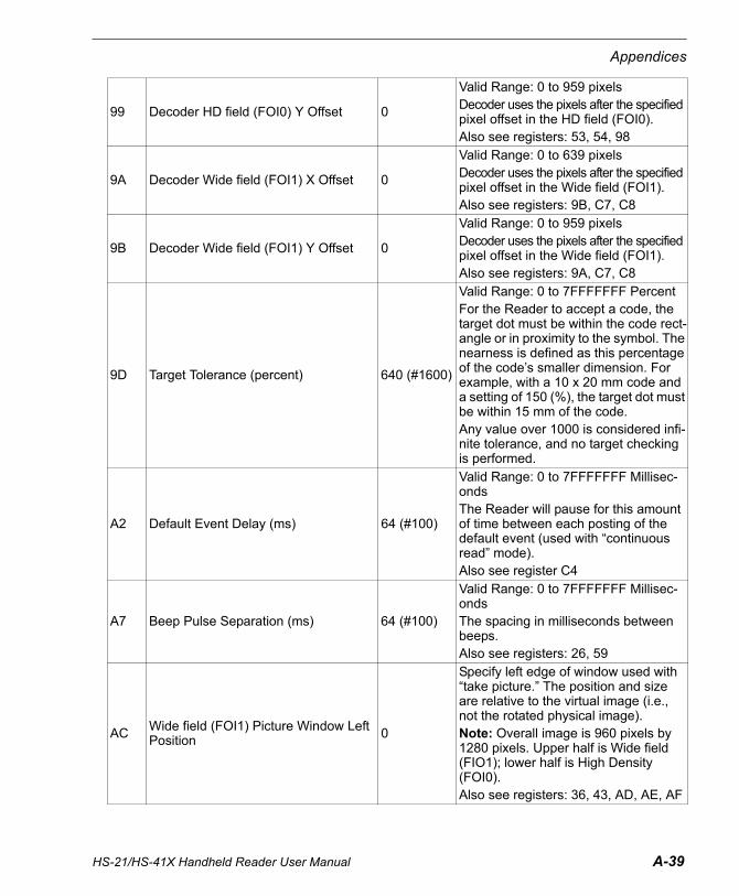
HS-21/HS-41X Handheld Reader User Manual A-39
Appendices
99 Decoder HD field (FOI0) Y Offset 0
Valid Range: 0 to 959 pixels Decoder uses the pixels after the specified pixel offset in the HD field (FOI0).Also see registers: 53, 54, 98
9A Decoder Wide field (FOI1) X Offset 0
Valid Range: 0 to 639 pixels Decoder uses the pixels after the specified pixel offset in the Wide field (FOI1).Also see registers: 9B, C7, C8
9B Decoder Wide field (FOI1) Y Offset 0
Valid Range: 0 to 959 pixels Decoder uses the pixels after the specified pixel offset in the Wide field (FOI1).Also see registers: 9A, C7, C8
9D Target Tolerance (percent) 640 (#1600)
Valid Range: 0 to 7FFFFFFF PercentFor the Reader to accept a code, the target dot must be within the code rect-angle or in proximity to the symbol. The nearness is defined as this percentage of the code’s smaller dimension. For example, with a 10 x 20 mm code and a setting of 150 (%), the target dot must be within 15 mm of the code.Any value over 1000 is considered infi-nite tolerance, and no target checking is performed.
A2 Default Event Delay (ms) 64 (#100)
Valid Range: 0 to 7FFFFFFF Millisec-ondsThe Reader will pause for this amount of time between each posting of the default event (used with “continuous read” mode).Also see register C4
A7 Beep Pulse Separation (ms) 64 (#100)
Valid Range: 0 to 7FFFFFFF Millisec-ondsThe spacing in milliseconds between beeps. Also see registers: 26, 59
AC Wide field (FOI1) Picture Window Left Position 0
Specify left edge of window used with “take picture.” The position and size are relative to the virtual image (i.e., not the rotated physical image).Note: Overall image is 960 pixels by 1280 pixels. Upper half is Wide field (FIO1); lower half is High Density (FOI0).Also see registers: 36, 43, AD, AE, AF

A-40 HS-21/HS-41X Handheld Reader User Manual
Serial Commands
AD Wide field (FOI1) Picture Window Upper Position 0
Specify upper edge of window used with “take picture.” The position and size are relative to the virtual image (i.e., not the rotated physical image).Note: Overall image is 960 pixels by 1280 pixels. Upper half is Wide field (FIO1); lower half is High Density (FOI0).Also see registers: 36, 43, AC, AE, AF
AE Wide field (FOI1) Picture Window Width
500 (#1280)
Specify width of window used with “take picture.” The position and size are relative to the virtual image (i.e., not the rotated physical image).Note: Overall image is 960 pixels by 1280 pixels. Upper half is Wide field (FIO1); lower half is High Density (FOI0).Also see registers: 36, 43, AC, AD, AF
AFWide field (FOI1) Picture Window Height 3C0 (#960)
Specify height of window used with “take picture.” The position and size are relative to the virtual image (i.e., not the rotated physical image).Note: Overall image is 960 pixels by 1280 pixels. Upper half is Wide field (FIO1); lower half is High Density (FOI0).Also see registers: 36, 43, AC, AD, AE
B0 Target On Before Picture (ms) 3E8 (#1000)
Valid Range: 0 to 7FFFFFFF Millisec-onds0: Target off before picture captureAlso see registers: 36, 43, AC, AD, AE
B3 Number Of Retries Before Reader Gives Up Sending Packet
3Note: The value 1 is defined as the original send attempt but no resends.Also see register: 42
BF USB Keyboard Poll Rate A (#10)
Valid Range: 1 to FF (#255) Millisec-ondsThe Host is requested to poll the USB device at the specified period.

HS-21/HS-41X Handheld Reader User Manual A-41
Appendices
C4 Default (Continuous) Event FF (#255)
The default value of FF (idle event) dis-ables “continuous scanning”. Use one of the read events to enable “continu-ous scanning.” See setting 39 for the list of events.When no button is pressed but the Reader is still in active mode (i.e., not power-saving idle or sleep modes), this event will be posted. Also see register: 39
C7 Decoder Wide field (FOI1) Width 280 (#640)
Valid Range: 1 to 280 (#640) pixelsDecoder uses only the specified pixel height in the Wide field (FOI1).Also see registers: 9A, 9B, C8
C8 Decoder Wide field (FOI1) Height 3C0 (#960)
Valid Range: 1 to 3C0 (#960) pixelsDecoder uses only the specified pixel height in the Wide field (FOI1).Also see registers: 9A, 9B, C7
C9 Interleaved 2 Of 5 Lengths 0
FFFFFFFC: 2 and 4 digit disabledFFFFFFFD: 2 digit enabledFFFFFFFE: 4 digit enabledAlso see registers: 6E, 71
CF Macro PDF417 Symbology 00: Disabled1: EnabledAlso see registers: 29, 2A
D8 Composite Codes Require Both Ele-ments 1
0: Accept any composite element1: Only accept composite codes if both elements could be decoded.Also see register 4A
EB Maximum Reader To Host Packet Data Size
4000 (#16384) Valid Range: 1 to 4000 (#16384)
EC Host Acknowledgement Time Limit Multiplier (ms)
F (#15)
Valid Range: 0 to 7FFFFFFF Millisec-ondsWhen Expect Acknowledgement From Host (register 42) is nonzero, the Reader will wait up to Host Acknowl-edgement Time Limit (register 37) + dataSize * Host Acknowledgement Time Limit Multiplier (register EC) milli-seconds to receive an acknowledge-ment from the Host.

A-42 HS-21/HS-41X Handheld Reader User Manual
Serial Commands
EDPrefix Decode Result With AIM Sym-bology Identifiers 0
0: Don’t prefix with AIM identifier1: Prefix decode result with ISO/IEC standard 15424/AIM symbology identi-fier
F0 Allow Code 128 Short Margin 10: Disabled1: Enabled
F6 Code 39 Short Margin 1
0: Disallow short margin Code 39 sym-bol decoding1: Allow short margin Code 39 symbol decoding
F8 PharmaCode Symbology 00: Disabled1: Enabled
F9 PharmaCode Bar Count 1004 (#4100)
Valid Range: Each 8 bits can be 04 to 10 (#16)Bit 0 – Bit 7: min bar count, 04 to 10 (#16)Bit 9 – Bit 15: max bar count, 04 to 10 (#16)
FA PharmaCode Min Value F (#15)Valid Range: F (#15) to 1FFFE (#131070)
FB PharmaCode Max Value 1FFFE (#131070)
Valid Range: F (#15) to 1FFFE (#131070)
10B Enable JavaScript 1
0: Disabled1: EnabledWhen set to 0 installed scripts are dis-abled. This can be useful from boot mode for recovering the unit if a non-responsive script is installed.
10D Data Matrix Symbol Identification Effort 2
0: Normal effort1: Increase effort2: Max effortIncreases the decoder’s effort to find a Data Matrix symbol in an image.
12C Data Matrix Improvement 1
0: Disabled1: EnabledImproves the decoding capability of the Reader on low contrast or pixelated Data Matrix bar codes

HS-21/HS-41X Handheld Reader User Manual A-43
Appendices
12D Hong Kong 2 Of 5 Symbology 0
Binary Dip Switch
137 PDF417 Handle Invalid Shift 0
0: Disabled1: EnabledAllows the decoding of PDF417 bar codes that were improperly encoded
159 Ignore Duplicate Code (ms) 0
Valid Range: 0 to 7FFFFFF Millisec-ondsConsecutive duplicate codes (i.e., codes that contain the same data) are blocked for this amount of time (in milli-seconds). 0 turns off blocking of dupli-cate codes.
1D7 Morphology 0
Binary Dip Switch
1D8 BC412 Status 1 0: Disabled1: Enabled
1D9 UPC/EAN Status 1 0: Disabled1: Enabled
Bit Controls Value
1-0 Technique0: None1: Erode2: Dilate
3-2 Size0: Small 3x31: Med. 5x52: Large 7x7
Bit Controls Value
0 Hong Kong 2 of 5 decoding
0: Disabled1: Enabled
1 1 Digit Symbol Allowed
0: Disabled1: Enabled
2 2 Digit Symbol Allowed
0: Disabled1: Enabled

A-44 HS-21/HS-41X Handheld Reader User Manual
Serial Commands
1DC Pharmacode Settings 28A40
Binary Dip Switch
1EA Good Read Duration (ms) C8 (#200) Valid Range: 0 to 7FFFFFF Milliseconds 1EB Decoder Data Matrix Module Size 32 (#50)
20E Motion Detection: Start Delay (ms) 0
Valid Range: 0 to 7FFFFFFF Millisec-onds A built-in delay of 200 ms prevents motion detect to detect motion right after a successful decode. This allows the bar code to be removed without triggering a new decode. Use this to add an additional delay amount.Also see register: 86
Bit Controls Value
0 Direction0: Forward1: Reverse
1 Fixed Symbol Length Status
0: Disabled1: Enabled
3-2 Bar Width Status
0 = Mixed1 = All Narrow2 = All Wide3 = Use Fixed Threshold
8-4 Minimum Number of Bars Value
4-10 (#16) (Default 4)
13-9 Fixed Symbol Length Value
1-10 (16) (Default 5)
29-14
Fixed Bar Width Threshold
0-FFFF (#65535) (Default 10)

HS-21/HS-41X Handheld Reader User Manual A-45
Appendices
CRB SystemThe CRB system is a convenient method for creating and maintaining a set of commands that can be easily sent to the reader. These CRB files can be created in any text editor with the file extension of .crb. The CRB system accepts all of the valid text commands. The most commonly used commands are J, N, P, and ~. There should be one command per line. The CRB file may contain empty lines and comments as well.
The .crb files can be sent directly to the reader using the normal file transfer. As CRB files are just a list of text commands, they can also be sent by a serial terminal program. Note: if using a serial terminal program the reader will first need to be set to “text command mode”; see Text Commands.
You can request a copy of all reader configuration settings in .crb format.
Example CRC16 C CodeCRC16.h:
// crc16.h#ifndef crc16_h#define crc16_h#include <stdint.h>#include <stddef.h>#ifdef __cplusplusextern "C" {#endiftypedef uint16_t crc_t;crc_t crc( crc_t initialCrc
, const unsigned char* bufPtr, size_t length
);#ifdef __cplusplus} // extern "C"#endif#endif/*eof*/

A-46 HS-21/HS-41X Handheld Reader User Manual
Serial Commands
CRC16.c:
// crc16.c#include <crc16.h>crc_t crc( crc_t initialCrc
, const unsigned char* p, size_t n
){
enum{
crcBits = 16,charBits = 8,diffBits = crcBits - charBits
};crc_t c = initialCrc;#include "crc16tab.h"while( n-- )
c = (c << charBits) ^ crcTab[( c >> diffBits ) ^ *p++];return c;
}/*eof*/

HS-21/HS-41X Handheld Reader User Manual A-47
Appendices
CRC16tab.h:
/* crc16tab.h * crc16 table of partial remainders generated by * mkcrctab.c with polynomial 1021. * included only from within crc() function in file crc16.c */static const crc_t crcTab[] ={
0x0000, 0x1021, 0x2042, 0x3063, 0x4084, 0x50a5, 0x60c6, 0x70e7, 0x8108, 0x9129, 0xa14a, 0xb16b, 0xc18c, 0xd1ad, 0xe1ce, 0xf1ef, 0x1231, 0x0210, 0x3273, 0x2252, 0x52b5, 0x4294, 0x72f7, 0x62d6, 0x9339, 0x8318, 0xb37b, 0xa35a, 0xd3bd, 0xc39c, 0xf3ff, 0xe3de, 0x2462, 0x3443, 0x0420, 0x1401, 0x64e6, 0x74c7, 0x44a4, 0x5485, 0xa56a, 0xb54b, 0x8528, 0x9509, 0xe5ee, 0xf5cf, 0xc5ac, 0xd58d, 0x3653, 0x2672, 0x1611, 0x0630, 0x76d7, 0x66f6, 0x5695, 0x46b4, 0xb75b, 0xa77a, 0x9719, 0x8738, 0xf7df, 0xe7fe, 0xd79d, 0xc7bc, 0x48c4, 0x58e5, 0x6886, 0x78a7, 0x0840, 0x1861, 0x2802, 0x3823, 0xc9cc, 0xd9ed, 0xe98e, 0xf9af, 0x8948, 0x9969, 0xa90a, 0xb92b, 0x5af5, 0x4ad4, 0x7ab7, 0x6a96, 0x1a71, 0x0a50, 0x3a33, 0x2a12, 0xdbfd, 0xcbdc, 0xfbbf, 0xeb9e, 0x9b79, 0x8b58, 0xbb3b, 0xab1a, 0x6ca6, 0x7c87, 0x4ce4, 0x5cc5, 0x2c22, 0x3c03, 0x0c60, 0x1c41, 0xedae, 0xfd8f, 0xcdec, 0xddcd, 0xad2a, 0xbd0b, 0x8d68, 0x9d49, 0x7e97, 0x6eb6, 0x5ed5, 0x4ef4, 0x3e13, 0x2e32, 0x1e51, 0x0e70, 0xff9f, 0xefbe, 0xdfdd, 0xcffc, 0xbf1b, 0xaf3a, 0x9f59, 0x8f78, 0x9188, 0x81a9, 0xb1ca, 0xa1eb, 0xd10c, 0xc12d, 0xf14e, 0xe16f, 0x1080, 0x00a1, 0x30c2, 0x20e3, 0x5004, 0x4025, 0x7046, 0x6067, 0x83b9, 0x9398, 0xa3fb, 0xb3da, 0xc33d, 0xd31c, 0xe37f, 0xf35e, 0x02b1, 0x1290, 0x22f3, 0x32d2, 0x4235, 0x5214, 0x6277, 0x7256, 0xb5ea, 0xa5cb, 0x95a8, 0x8589, 0xf56e, 0xe54f, 0xd52c, 0xc50d, 0x34e2, 0x24c3, 0x14a0, 0x0481, 0x7466, 0x6447, 0x5424, 0x4405, 0xa7db, 0xb7fa, 0x8799, 0x97b8, 0xe75f, 0xf77e, 0xc71d, 0xd73c, 0x26d3, 0x36f2, 0x0691, 0x16b0, 0x6657, 0x7676, 0x4615, 0x5634, 0xd94c, 0xc96d, 0xf90e, 0xe92f, 0x99c8, 0x89e9, 0xb98a, 0xa9ab, 0x5844, 0x4865, 0x7806, 0x6827, 0x18c0, 0x08e1, 0x3882, 0x28a3, 0xcb7d, 0xdb5c, 0xeb3f, 0xfb1e, 0x8bf9, 0x9bd8, 0xabbb, 0xbb9a, 0x4a75, 0x5a54, 0x6a37, 0x7a16, 0x0af1, 0x1ad0, 0x2ab3, 0x3a92, 0xfd2e, 0xed0f, 0xdd6c, 0xcd4d, 0xbdaa, 0xad8b, 0x9de8, 0x8dc9, 0x7c26, 0x6c07, 0x5c64, 0x4c45, 0x3ca2, 0x2c83, 0x1ce0, 0x0cc1, 0xef1f, 0xff3e, 0xcf5d, 0xdf7c, 0xaf9b, 0xbfba, 0x8fd9, 0x9ff8, 0x6e17, 0x7e36, 0x4e55, 0x5e74, 0x2e93, 0x3eb2, 0x0ed1, 0x1ef0,};
/*eof*/

A-48 HS-21/HS-41X Handheld Reader User Manual
Communications Protocol
Appendix E — Communications ProtocolCommunications Protocol Command Table
Protocol Command(Mnemonic displayed on menu)
Control Characters (Entered in menu or serial command)
Hex Value
Effect of Command
RES ^D 04 Reset
REQ ^E 05 Request
EOT ^D 04 Reset
STX ^B 02 Start of Text
ETX ^C 03 End of Text
ACK ^F 06 Acknowledge
NAK ^U 15 Negative Acknowledge
XON ^Q 11 Begin Transmission
XOFF ^S 13 Stop Transmission

HS-21/HS-41X Handheld Reader User Manual A-49
Appendices
Appendix F — ASCII Table
Dec Hex Mne Ctrl Dec Hex Ch Dec Hex Ch Dec Hex Ch00 00 NUL ^@ 32 20 SP 64 40 @ 96 60 `01 01 SOH ^A 33 21 ! 65 41 A 97 61 a02 02 STX ^B 34 22 “ 66 42 B 98 62 b03 03 ETX ^C 35 23 # 67 43 C 99 63 c04 04 EOT ^D 36 24 $ 68 44 D 100 64 d05 05 ENQ ^E 37 25 % 69 45 E 101 65 e06 06 ACK ^F 38 26 & 70 46 F 102 66 f07 07 BEL ^G 39 27 ' 71 47 G 103 67 g08 08 BS ^H 40 28 ( 72 48 H 104 68 h09 09 HT ^I 41 29 ) 73 49 I 105 69 i10 0A LF ^J 42 2A * 74 4A J 106 6A j11 0B VT ^K 43 2B + 75 4B K 107 6B k12 0C FF ^L 44 2C , 76 4C L 108 6C l13 0D CR ^M 45 2D - 77 4D M 109 6D m14 0E SO ^N 46 2E . 78 4E N 110 6E n15 0F SI ^O 47 2F / 79 4F O 111 6F o16 10 DLE ^P 48 30 0 80 50 P 112 70 p17 11 DC1 ^Q 49 31 1 81 51 Q 113 71 q18 12 DC2 ^R 50 32 2 82 52 R 114 72 r19 13 DC3 ^S 51 33 3 83 53 S 115 73 s20 14 DC4 ^T 52 34 4 84 54 T 116 74 t21 15 NAK ^U 53 35 5 85 55 U 117 75 u22 16 SYN ^V 54 36 6 86 56 V 118 76 v23 17 ETB ^W 55 37 7 87 57 W 119 77 w24 18 CAN ^X 56 38 8 88 58 X 120 78 x25 19 EM ^Y 57 39 9 89 59 Y 121 79 y26 1A SUB ^Z 58 3A : 90 5A Z 122 7A z27 1B ESC ^[ 59 3B ; 91 5B [ 123 7B {28 1C FS ^\ 60 3C < 92 5C \ 124 7C |29 1D GS ^] 61 3D = 93 5D ] 125 7D }30 1E RS ^^ 62 3E > 94 5E ^ 126 7E ~31 1F US ^_ 63 3F ? 95 5F _ 127 7F D

A-50 HS-21/HS-41X Handheld Reader User Manual
Maintenance
Appendix G — MaintenanceThe HS-21 and HS-41X Handheld Readers require only a minimum of maintenance to operate.
Cleaning the HS-21 and HS-41X Handheld ReadersThe following substances are approved for cleaning of the HS-21 and HS-41X.
Product Chemical Content
Alcohol Wipes Isopropyl Alcohol
CaviWipes® Disinfecting Towelettes and CaviCide®
Isopropyl Alcohol, Ethylene Glycol Monobutyl Ether
Clorox® Disinfecting Wipes
Isopropyl Alcohol, n-Alkyl Dimethyl-benzyl Ammonium Chloride, n-Alkyl Dimethyl Ethylbenzyl Ammonium Chloride, Alkyl Polyglucoside, Propylene Glycol Propyl Ether
Clorox® Bleach Solution (10% Clorox bleach, 90% tap water)
Sodium Hypochlorite, Sodium Chloride, Sodium Carbonate, Sodium Hydroxide, Sodium Polyacrylate
Formula 409® Glass and Surface Cleaner
n-Alkyl Dimethyl Benzyl Ammonium Chloride, n-Propoxypropanol
Sani-Cloth® HB, Super Sani-Cloth® Germicidal, Sani-Cloth® Plus Germicidal Disposable Wipes
Quaternary Ammonium Compounds/Chlorides
Virex® II Disinfectant Cleaner n-Alkyl Dimethyl Benzyl Ammonium Chloride, Didecyl Dimethyl Ammonium Chloride
Gentle dish soap and water

HS-21/HS-41X Handheld Reader User Manual A-51
Appendices
Appendix H — Glossary of TermsAberration — The failure of an optical lens to produce an exact point-to-point correspondence between the object and its resulting image. Various types are chromatic, spherical, coma, astigmatism and distortion.
Absorption — The loss of light of certain wavelengths as it passes through a material and is converted to heat or other forms of energy. (–)
Active Illumination — Lighting an area with a light source coordinated with the acquisition of an image. Strobed flash tubes and pulsed lasers are examples.
ADC — See Analog-to-Digital Converter.
A/D Converter — See Analog-to-Digital Converter.
AGC — See Automatic Gain Control.
Ambient Light — Light which is present in the environment of the front end of a reader and generated from outside sources. This light, unless used for actual illumination, will be treated as background noise by the reader.
Analog — A smooth, continuous voltage or current signal or function whose magnitude (value) is the information.
Analog-to-Digital Converter (A/D Converter or ADC) — A device that converts an analog voltage or current signal to a discrete series of digitally encoded numbers (signal) for computer processing.
Application-Specific Integrated Circuit (ASIC) — An integrated circuit that is customized for a particular kind of use, rather than general use. All vision system elements including firmware can be integrated into one ASIC.
Automatic Gain Control (AGC) — Adjustment to signal strength that seeks to maintain a constant level regardless of the distance between a reader and symbol.
Auxiliary Port — RS-232 connection to an auxiliary terminal or device for remote viewing.
Baud Rate — The number of discrete signal events per second; bits per second.
CCD — See Charge-Coupled Device.
Charge-Coupled Device (CCD) — A semiconductor device with an array of light-sensitive elements that converts light images into electrical signals.
Check Character — A Modulus 43 or Modulus 10 character that is added to encoded symbol data for additional data integrity.Connector — A plug or socket on a device or cable providing in/out connectivity for various circuits and pins.Concentrator — Intermediary device that relays data from readers to a host and commands from the host to the readers or other devices.DAC — See Digital-to-Analog Converter.Daisy Chain — Linkage of primary and secondary readers allowing data to be relayed up to the host via auxiliary port connections. Decode — A Good Read. The successful interpretation and output of the information encoded in a symbol.Default — Restores ROM or flash settings and initializes serial commands.

A-52 HS-21/HS-41X Handheld Reader User Manual
Glossary of Terms
Delimited — A delimited command or field is bracketed by predefined characters.Decode Rate — The number of good reads per second ahieved by a reader.Darkfield Illumination — Lighting of objects, surfaces, or particles at very shallow or low angles, so that light does not directly enter a reader’s optical hardware.Depth-of-Field — The in-focus range of a reader. Measured from the distance behind an object to the distance in front of the object with all objects appearing in focus. Diffused Lighting — Scattered soft lighting from a wide variety of angles used to eliminate shadows and specular glints from profiled, highly reflective surfaces.Digital-to-Analog Converter (DAC) — A VLSI circuit used to convert digitally processed images to analog for display on a monitor.Digital Signal Processor (DSP) — A VLSI chip designed for ultra-high-speed arithmetic processing.Discrete I/O — Inputs and outputs characterized by discrete signal transitions from one voltage level to another so that digital switching can occur.Direct Memory Access (DMA) — A capability provided by some computer bus architectures that allows data to be sent directly to memory from an attached device.DSP — See Digital Signal Processor.EPROM — See Erasable Programmable Read-Only Memory.Embedded Memory — Onboard memory device such as EPROM or flash.End of Read Cycle — The time or condition at which the reader stops expecting symbol information to decode.Erasable Programmable Read-Only Memory (EPROM) — A memory chip that retains data when its power supply is turned off; “non-volatile memory”.External Edge — Allows a read cycle to be initiated by a trigger signal from an object detector when it detects the appearance of an object (rising edge). The read cycle ends with a good read, a timeout, or a new trigger.External Level — Allows a read cycle to be initiated by a trigger signal from an object detector. The read cycle ends when the object moves out of the detector’s range.Falling Edge — A change of state (to inactive) associated with a level trigger.Field-Programmable Gate Array (FPGA) — A semiconductor device containing programmable interconnects and logic components.Firmware — Software hard-coded in non-volatile memory (ROM), and closely tied to specific pieces of hardware.Fixed Symbol Length — Increases data integrity by ensuring that only a symbol length will be accepted.Focal Distance — In optics, the distance from the lens to the focal plane.Focal Plane — Usually found at the image sensor, it is a plane perpendicular to the lens axis at the point of focus (–).Focus — Any given point in an image at which light converges; the focal point.FPGA — See Field-Programmable Gate Array.Full Duplex — A communications system in which signals can travel simultaneously between devices.
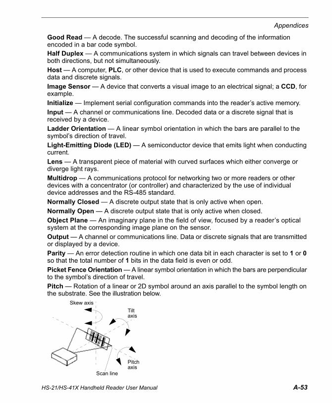
HS-21/HS-41X Handheld Reader User Manual A-53
Appendices
Good Read — A decode. The successful scanning and decoding of the information encoded in a bar code symbol.Half Duplex — A communications system in which signals can travel between devices in both directions, but not simultaneously.
Host — A computer, PLC, or other device that is used to execute commands and process data and discrete signals.
Image Sensor — A device that converts a visual image to an electrical signal; a CCD, for example.
Initialize — Implement serial configuration commands into the reader’s active memory.
Input — A channel or communications line. Decoded data or a discrete signal that is received by a device.
Ladder Orientation — A linear symbol orientation in which the bars are parallel to the symbol’s direction of travel.
Light-Emitting Diode (LED) — A semiconductor device that emits light when conducting current.
Lens — A transparent piece of material with curved surfaces which either converge or diverge light rays.
Multidrop — A communications protocol for networking two or more readers or other devices with a concentrator (or controller) and characterized by the use of individual device addresses and the RS-485 standard.
Normally Closed — A discrete output state that is only active when open.
Normally Open — A discrete output state that is only active when closed.
Object Plane — An imaginary plane in the field of view, focused by a reader’s optical system at the corresponding image plane on the sensor.
Output — A channel or communications line. Data or discrete signals that are transmitted or displayed by a device.
Parity — An error detection routine in which one data bit in each character is set to 1 or 0 so that the total number of 1 bits in the data field is even or odd.
Picket Fence Orientation — A linear symbol orientation in which the bars are perpendicular to the symbol’s direction of travel.
Pitch — Rotation of a linear or 2D symbol around an axis parallel to the symbol length on the substrate. See the illustration below.
Skew axis
Tilt axis
Pitch axis
Scan line
A-54 HS-21/HS-41X Handheld Reader User Manual
Glossary of Terms
PLC — See Programmable Logic Controller.
Port — Logical circuit for data entry and exit. (One or more ports may be included within a single connector.)
Programmable Logic Controller (PLC) — An electronic device used in industrial automation environments such as factory assembly lines and automotive manufacturing facilities.
Protocol — The rules for communication between devices, providing a means to control the orderly flow of information between linked devices.
Random Access Memory (RAM) — A data storage system used in computers, composed of integrated circuits that allow access to stored data in any sequence without movement of physical parts.
Read Cycle — A programmed period of time or condition during which a reader will accept symbol input.
Read-Only Memory (ROM) — A data storage medium used in computers and other electronics, primarily used to distribute firmware.
Skew — Rotation of a linear or 2D symbol around an axis parallel to the symbol height on the substrate. See the illustration under the definition of Pitch.
Substrate — The surface upon which a symbol is printed, stamped, or etched.
Symbol Transitions — The transition of bars and spaces on a symbol, used to detect the presence of a symbol on an object.
Symbology — A symbol type, such as Code 39 or Code 128, with special rules to define the widths and positions of bars and spaces to represent specific numeric or alphanumeric information.
Tilt — Rotation of a linear or 2D symbol around an axis perpendicular to the substrate. See the illustration under the definition of Pitch.
Trigger — A signal, transition, or character string that initiates a read cycle.
Very Large-Scale Integration (VLSI) — The creation of integrated circuits by combining thousands of transistor-based circuits on a single chip.
VLSI — See Very Large-Scale Integration.