HS-1200 Instruction Manual - Full Compass Systems€¦ · Keyer Control ... how to register please...
42
Transcript of HS-1200 Instruction Manual - Full Compass Systems€¦ · Keyer Control ... how to register please...


2
Contents
FCC COMPLIANCE STATEMENT ................................................................................................................ 4 WARNINGS AND PRECAUTIONS .............................................................................................................. 4 WARRANTY ............................................................................................................................................ 5
STANDARD WARRANTY ........................................................................................................................................ 5 TWO YEAR WARRANTY ........................................................................................................................................ 5
DISPOSAL ............................................................................................................................................... 5 1. INTRODUCTION ................................................................................................................................ 6
1.1 FEATURES ................................................................................................................................................ 6 2. REAR PANEL ..................................................................................................................................... 7
2.1 REAR PANEL CONNECTIONS ......................................................................................................................... 7 3. CONTROL PANEL ............................................................................................................................. 10
3.1 SWITCHER CONTROL PANEL....................................................................................................................... 10 User Memory and Function Keys .............................................................................................................. 10 Menu Control ............................................................................................................................................ 11 Keyer Selection ......................................................................................................................................... 11 Keyer Source ............................................................................................................................................. 12 PIP Effect ................................................................................................................................................... 12 Background Transition & GRAB ................................................................................................................ 12 Wipe Border Setting ................................................................................................................................. 12 Wipe Transition Selection ......................................................................................................................... 13 Program & Preview Source Row ............................................................................................................... 13 Transition Effect ........................................................................................................................................ 14 Audio Control ............................................................................................................................................ 15
3.2 MONITOR CONTROL PANEL ....................................................................................................................... 16 4. SWITCHER OSD MENU OVERVIEW .................................................................................................. 18 5. SWITCHER OSD MENU FUNCTIONS ................................................................................................. 24
5.1 START ................................................................................................................................................... 24 Transition .................................................................................................................................................. 24 Wipe Effects .............................................................................................................................................. 24 Border ....................................................................................................................................................... 24 Position ..................................................................................................................................................... 25 Matte ........................................................................................................................................................ 25
5.2 KEYER ................................................................................................................................................... 25 Keyer Control ............................................................................................................................................ 25 Key Source ................................................................................................................................................ 26 Fill Source ................................................................................................................................................. 26 Mask ......................................................................................................................................................... 26
5.3 CHROMA ............................................................................................................................................... 26 Keyer ......................................................................................................................................................... 26 CK Setup .................................................................................................................................................... 26 Mask ......................................................................................................................................................... 27
5.4 P-IN-P .................................................................................................................................................. 27 Position ..................................................................................................................................................... 27 Border ....................................................................................................................................................... 28

3
Border Width ............................................................................................................................................ 28 Crop .......................................................................................................................................................... 28
5.5 P-IN-P LITE ............................................................................................................................................ 28 Position ..................................................................................................................................................... 28 Border ....................................................................................................................................................... 29 Crop .......................................................................................................................................................... 29
5.6 INPUTS ................................................................................................................................................. 29 Input 1-4 ................................................................................................................................................... 29 Freeze ....................................................................................................................................................... 29 Crosspoint ................................................................................................................................................. 30
5.7 OUTPUTS .............................................................................................................................................. 30 Outputs ..................................................................................................................................................... 30 Audio ........................................................................................................................................................ 30 GPI Out ..................................................................................................................................................... 31 Multiviewer .............................................................................................................................................. 31
5.8 STILLS ................................................................................................................................................... 31 Load Still ................................................................................................................................................... 31 Save Still ................................................................................................................................................... 32 Freeze ....................................................................................................................................................... 32
5.9 USER MEMS .......................................................................................................................................... 32 Load Memory ........................................................................................................................................... 32 Save Memory ............................................................................................................................................ 32
5.10 SETUP ................................................................................................................................................... 33 Menu Preference ...................................................................................................................................... 33 Standard ................................................................................................................................................... 33 Menu Mode .............................................................................................................................................. 33 Auto Save .................................................................................................................................................. 34 Factory Default ......................................................................................................................................... 34 Reset Names ............................................................................................................................................. 34 Language .................................................................................................................................................. 34 Software ................................................................................................................................................... 34
6. MONITOR OSD MENU OPTIONS ...................................................................................................... 35 7. FIRMWARE UPDATE PROCEDURE .................................................................................................... 36 8. GPI CONNECTION ........................................................................................................................... 37 9. TALLY OUTPUTS .............................................................................................................................. 38 10. DIMENSIONS ............................................................................................................................... 39 11. SPECIFICATIONS ........................................................................................................................... 40 SERVICE AND SUPPORT ......................................................................................................................... 42 Disclaimer of Product and Services The information offered in this instruction manual is intended as a guide only. At all times, Datavideo Technologies will try to give correct, complete and suitable information. However, Datavideo Technologies cannot exclude that some information in this manual, from time to time, may not be correct or may be incomplete. This manual may contain typing errors, omissions or incorrect information. Datavideo Technologies always recommend that you double check the information in this document for accuracy before making any purchase decision or using the product. Datavideo Technologies is not responsible for any omissions or errors, or for any subsequent loss or damage caused by using the information contained within this manual. Further advice on the content of this manual or on the product can be obtained by contacting your local Datavideo Office or dealer.

4
FCC Compliance Statement This device complies with part 15 of the FCC rules. Operation is subject to the following two conditions: 1. This device may not cause harmful interference, and 2. This device must accept any interference received, including interference that may cause undesired
operation.
Warnings and Precautions 1. Read all of these warnings and save them for later reference.
2. Follow all warnings and instructions marked on this unit.
3. Unplug this unit from the wall outlet before cleaning. Do not use liquid or aerosol cleaners. Use a damp cloth for cleaning.
4. Do not use this unit in or near water.
5. Do not place this unit on an unstable cart, stand, or table. The unit may fall, causing serious damage.
6. Slots and openings on the cabinet top, back, and bottom are provided for ventilation. To ensure safe and reliable operation of this unit, and to protect it from overheating, do not block or cover these openings. Do not place this unit on a bed, sofa, rug, or similar surface, as the ventilation openings on the bottom of the cabinet will be blocked. This unit should never be placed near or over a heat register or radiator. This unit should not be placed in a built-in installation unless proper ventilation is provided.
7. This product should only be operated from the type of power source indicated on the marking label of the AC adapter. If you are not sure of the type of power available, consult your Datavideo dealer or your local power company.
8. Do not allow anything to rest on the power cord. Do not locate this unit where the power cord will be walked on, rolled over, or otherwise stressed.
9. If an extension cord must be used with this unit, make sure that the total of the ampere ratings on the products plugged into the extension cord do not exceed the extension cord’s rating.
10. Make sure that the total amperes of all the units that are plugged into a single wall outlet do not exceed 15 amperes.
11. Never push objects of any kind into this unit through the cabinet ventilation slots, as they may touch dangerous voltage points or short out parts that could result in risk of fire or electric shock. Never spill liquid of any kind onto or into this unit.
12. Except as specifically explained elsewhere in this manual, do not attempt to service this product yourself. Opening or removing covers that are marked “Do Not Remove” may expose you to dangerous voltage points or other risks, and will void your warranty. Refer all service issues to qualified service personnel.
13. Unplug this product from the wall outlet and refer to qualified service personnel under the following conditions:
a. When the power cord is damaged or frayed;
b. When liquid has spilled into the unit;
c. When the product has been exposed to rain or water;
d. When the product does not operate normally under normal operating conditions. Adjust only those controls that are covered by the operating instructions in this manual; improper

5
adjustment of other controls may result in damage to the unit and may often require extensive work by a qualified technician to restore the unit to normal operation;
e. When the product has been dropped or the cabinet has been damaged;
f. When the product exhibits a distinct change in performance, indicating a need for service.
Warranty Standard Warranty
• Datavideo equipment is guaranteed against any manufacturing defects for one year from the date of purchase.
• The original purchase invoice or other documentary evidence should be supplied at the time of any request for repair under warranty.
• Damage caused by accident, misuse, unauthorized repairs, sand, grit or water is not covered by this warranty.
• All mail or transportation costs including insurance are at the expense of the owner.
• All other claims of any nature are not covered.
• Cables & batteries are not covered under warranty.
• Warranty only valid within the country or region of purchase.
• Your statutory rights are not affected.
Two Year Warranty
• All Datavideo products purchased after 01-Oct.-2008 qualify for a free one year extension to the standard Warranty, providing the product is registered with Datavideo within 30 days of purchase. For information on how to register please visit www.datavideo-tek.com or contact your local Datavideo office or authorized Distributors
• Certain parts with limited lifetime expectancy such as LCD Panels, DVD Drives, Hard Drives are only covered for the first 10,000 hours, or 1 year (whichever comes first).
Any second year warranty claims must be made to your local Datavideo office or one of its authorized Distributors before the extended warranty expires.
Disposal For EU Customers only - WEEE Marking
This symbol on the product indicates that it will not be treated as household waste. It must be handed over to the applicable take back scheme for the recycling of electrical and electronic equipment. For more detailed information about the recycling of this product, please contact your local Datavideo office.

6
1. Introduction The HS-1200 is a cost effective 6 channel broadcast-quality hand-carry mobile switcher, it is designed for live events and TV programs that need to mix a variety of video and audio sources. The HS-1200 is a lightweight, portable and powerful featured mobile studio solution. Friendly and advanced features include a 17.3-inch video monitor, which displays the multi-view. The Multi-view includes all the input sources, as well as preview and program. The HS-1200 is low power consumption and it is ideal for TV and video professionals working in outside broadcast or on-the-go video studios, such as theatres or conference centers. The HS-1200 is also a great value solution for the worship, education and AV market.
1.1 Features Video System
• 6 video inputs compatible with 1920x1080i video format • 4 HD-SDI and 2 HDMI video inputs • 2 HD-SDI video outputs and each output can be switched in the menu as:
- PROGRAM (with DSK) - Clean PROGRAM (without DSK) - Clean PREVIEW (without DSK) - MULTISCREEN - Input 1~6
• 1 HDMI video output only for multiviewer • Keyers for configuring DSK, luma key, chroma key and PiP • Wipe, Mix & Cut Transitions • Wipe Generator
- 32 Wipe Patterns, including Circle & Heart - Borders & Softness Control
• Full M/E Preview function Audio System
• 2 x XLR Analogue Audio Inputs Monitor System
• One 17.3-inch monitor with a resolution of 1600x900 dots • The blue button eliminates the red and green component of input signals for image calibration. • 6500K, 7500K, 9300K and custom color temperature settings in different environments. • 4:3 MARK LINE for shooting adjustment • 80% or 90% frame ratio

7
2. Rear Panel
1 Power Switch 7 HDMI Video Output (Multiview ONLY) 2 4 PIN XLR Power Input Connector 8 3 PIN XLR Audio Input 1 - 2 3 Monitor HDMI IN (External Video Input) 9 GPI Output Connector 4 HDMI Video Input 1 – 2 10 Ethernet Port 5 HD-SDI Video Input 1 – 4 11 Tally Signal Output 6 HD-SDI Video Output 1 – 2 12 USB Firmware Upgrade Port
2.1 Rear Panel Connections
1. POWER SWITCH
Switches the power On / Off.
2. DC Power Input
Connect the supplied 12V 5A PSU to this 4 PIN XLR socket.
3. Monitor HDMI IN (External Video Input)
The HS-1200 provides a useful connection for confidence monitoring of HDMI sources on location.
Connect one external HDMI input source for monitoring the live show.
1 2 3 12
4 5 6 7
8 9 10 11

8
Video Input Modules: The HS-1200 is equipped with six video input channels.
4. HDMI Video Input 1-2
The Video Input set has two HDMI ports. Note: Please set the INPUT SOURCE in the Switcher Menu.
5. SDI Video Input 1-4
The Video Input set has four SDI connectors. Note: Please set the INPUT SOURCE in the Switcher Menu.
6. SDI Video Output 1-2
The BNC output connector is a user defined SDI output. Note: Please set the OUTPUT SOURCE in the Switcher Menu.
7. HDMI Video Ouput (Multiview ONLY)
Connect the HDMI output port to an external monitor on which the Multiview is displayed. Note: This is NOT a user-defined output which is used for Multiview Display ONLY. The limitations of this port are: 1. No audio output. 2. Only 1080p is supported.
8. AUDIO Input 1-2
Supports two XLR Balanced Audio Input channels.

9
9. GPI Output
The GPI socket can be used for simple external control. Note: Please configure GPI settings in the Switcher Menu.
10. Ethernet Port Remote control interface
11. Tally Signal Output
Sends Red, and Green tally signals to each channel. Red indicates On-Air, and Green indicates next camera source.
12. USB Firmware Upgrade Port
Connect the USB drive containing the latest firmware files to this port and start the firmware upgrade process on the OSD MENU. Note: Please refer to the section on Firmware Update Procedure for firmware upgrade details.

10
3. Control Panel 3.1 Switcher Control Panel
1 User Memory & Function Keys 6 Background Transition & GRAB 2 Menu Control 7 Wipe Border Setting 3 Keyer Selection 8 Wipe Transition Selection 4 Keyer Source 9 Program & Preview source rows 5 PIP Effect 10 Transition Effect
User Memory and Function Keys
User Memory User Memory buttons 1-6 allow the user to recall and load previously saved switcher settings.
SHIFT There are 12 user memory locations. Under normal circumstances, Buttons USER 1 to 6 represent user memory locations 1 to 6. To load settings saved in locations 7 to 12 to buttons USER 1-6, simply press the SHIFT button. SAVE: User Memory Save The SAVE button saves the current switcher settings. To save, keep holding down this button and then select the User Memory number by pressing the corresponding User Memory button.
1 3 2 8 7 5
4 6
10
9

11
Normalise Button The NORM button resets the currently opened menu item to the default values.
Menu Control
Menu Control
Press the MENU button in the HS-1200 function section to enter the System Configuration Menu. Press the UP, DOWN, LEFT, and RIGHT arrow buttons to browse the menu options and change values. Use the ENTER button to save and confirm any setting that has been changed. To Exit, simply press the MENU button again.
Keyer Selection
Key 1 PGM enables key 1 on the Multi view and PGM output Key 2 PGM enables key 2 on the Multi view and PGM output
DSK 1 PGM enables DSK 1 on the Multi view and PGM output DSK 2 PGM enables DSK 2 on the Multi view and PGM output
Key 1 PVW enables key 1 on the Multi view and PVW output Key 2 PVW enables key 2 on the Multi view and PVW output
DSK 1 PVW enable DSK 1 on the Multi view and PVW output DSK 2 PVW enable DSK 2 on the Multi view and PVW output

12
Keyer Source
Selection of Keyer Source from Program / Preset Row Keep holding down one of these buttons to enter key select mode and fill select mode. Select key source from the Program row and fill source from the Preset row. The selected source button will flash.
KEYER SETUP Press this button to open Keyer configuration menu on the Multi view output, and the opened configuration menu corresponds to the selected keyer (Key 1/Key 2/DSK 1/DSK 2). DSK AUTO Auto DSK transition function either transitions “DSK 1 or DSK 2 individually” or transitions “DSK 1 and DSK 2 simultaneously”
PIP Effect
PIP enables the PIP key mode PIP LITE enables the PIP LITE key mode
Background Transition & GRAB
TRANS BG enables Background Transition between Program / Preset GRAB grabs the current Program video image
Wipe Border Setting
BDR ON/OFF turns the WIPE border function ON/OFF BDR SOFT configures the WIPE border softness BDR COLOR selects the WIPE border color BDR SIZE adjusts the WIPE border thickness

13
Wipe Transition Selection
WIPE Transition Selection The HS-1200 has 8 user defined wipe buttons that allow the user to select WIPE transition effect directly from the control panel. The REV button reverses the direction of the selected WIPE. All wipes can have an optional colour border applied. The wipe border width and colour are chosen within the menu system. Transitions can be performed manually using the T-Bar or automatically by using the SPEED and AUTO TAKE buttons.
Vertical Wipe Left to Right
Vertical Wipes from Centre to Left and Right sides
Upper Left corner Wipe to Lower Right corner
Box Wipe from Centre to outside edges
Diamond Wipe from Centre to outside edges
Circle Wipe from Centre to outside edges
Cross Wipe from Centre to outside edges
Heart Wipe from Centre to outside edges
Program & Preview Source Row
The Program row of buttons is the active channel, this is the live output. The active channel will appear as the Program Output. You can switch or CUT from one video source to another directly on the Program row. You will see the multi view Program output change as you press different keys along this top row of buttons.
The Preset row is the cued channel; this channel will appear in the Preview window. The Preset row selection decides which input will be transitioned next when using any of the transition controls.
Buttons 1, 2, 3, 4, 5 and 6 are video source buttons.

14
BLK Black background – the black background, for use on the Program and Preset row.
BG Background button – assigns a background colour or colour bars for use on the Program and Preset row.
Transition Effect
FTB Fade To Black, this button fades the current video program source to black. When pressed again it acts in reverse from complete black to the currently selected program video source.
SPEED There are three speed buttons which can be defined by the user. By pressing a speed button the user is choosing the rate of transition or time taken when using the AUTO TAKE button. Transition Speed (1, 2 and 3): Button 1= 12 frame duration, 2= 25 and 3= 50 at 1080i50 Button 1= 15 frame duration, 2= 30 and 3= 60 at 1080i60
PVW TRANS Transition shown on PVW only MIX This button enables MIX transition effect. WIPE This button enables WIPE transition effect. The WIPE button must be selected when a wipe effect transition between the selected Program and Preset sources is required. This WIPE effect is produced by moving the T-Bar manually or pressing the AUTO TRANS button.
CUT This performs a simple immediate switch from the current main source to the selected sub source. The selected transition wipe or MIX is not used.

15
AUTO TAKE This performs an automated switch from the current program source to the selected Preview source. The selected transition wipe or MIX will also be used. The timing of the transition is set by the chosen Speed button.
Audio Control
Headphone Socket ¼ “/ 6.3mm Stereo Headphone Socket for conventional headphones.
MUTE This button mutes the headphone audio.
Headphone Volume Control Controls Headphone or Headset volume level.
16
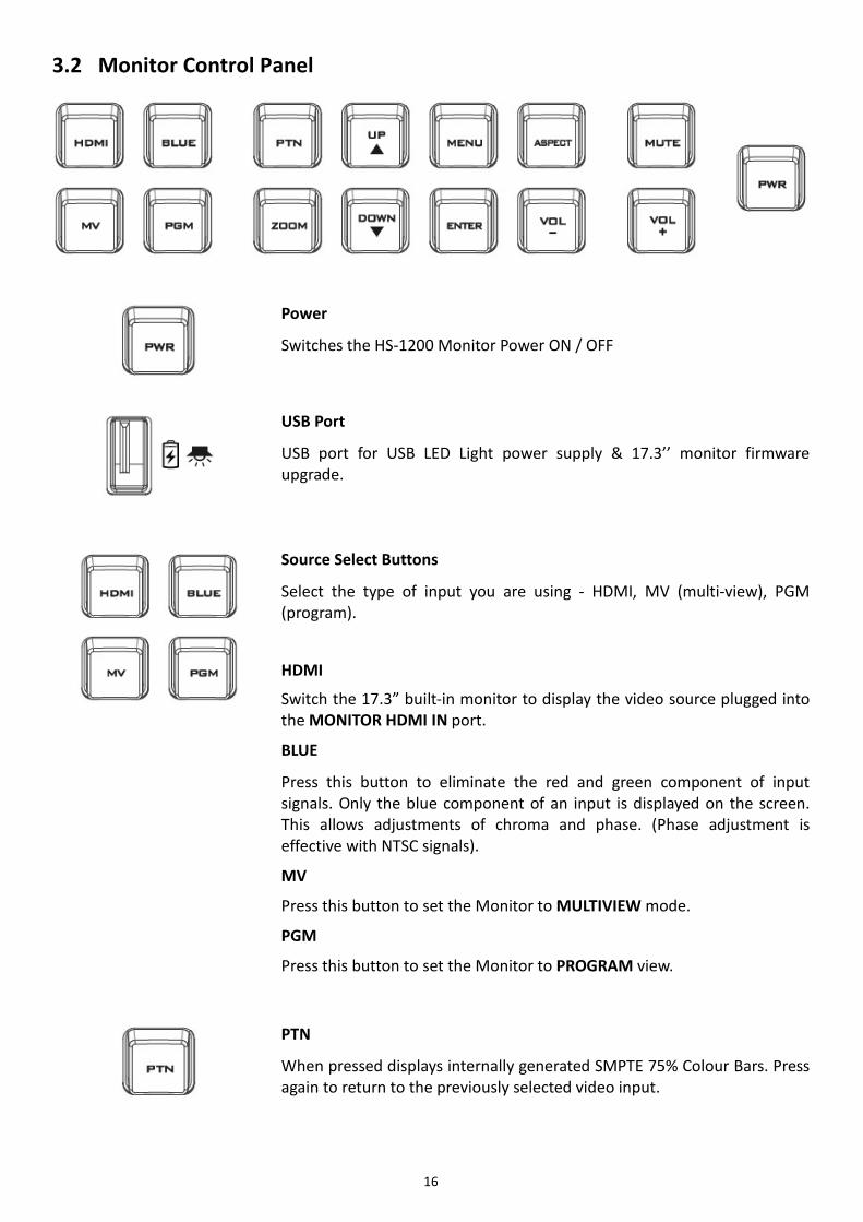
3.2 Monitor Control Panel
Power
Switches the HS-1200 Monitor Power ON / OFF
USB Port
USB port for USB LED Light power supply & 17.3’’ monitor firmware upgrade.
Source Select Buttons
Select the type of input you are using - HDMI, MV (multi-view), PGM (program).
HDMI
Switch the 17.3” built-in monitor to display the video source plugged into the MONITOR HDMI IN port.
BLUE
Press this button to eliminate the red and green component of input signals. Only the blue component of an input is displayed on the screen. This allows adjustments of chroma and phase. (Phase adjustment is effective with NTSC signals).
MV
Press this button to set the Monitor to MULTIVIEW mode.
PGM
Press this button to set the Monitor to PROGRAM view.
PTN
When pressed displays internally generated SMPTE 75% Colour Bars. Press again to return to the previously selected video input.

17
ZOOM
This feature is designed for use with HD-SDI and HDMI sources above 720p resolution. Press this button to zoom in to the video on the display. This is strictly a zooming function and does not alter the native aspect ratio of the source pixels to fill the screen.
The ZOOM button allows you to toggle the Pixel Zoom feature between zoom x1, x2, x4 and x8.
Menu Navigation Buttons
Display and navigate the set up menus - See Monitor Menu Options for more details.
Aspect Ratio Button
Sets the Aspect Ratio to 16:9 / 4:3 Volume Control
Adjusts the speaker / headphone volume up / down. MUTE
Mutes the audio from the internal speakers or headphone socket.

18
4. Switcher OSD MENU Overview
When the MENU button is pressed the Main Menu list is displayed on the HS-1200 monitor. This section covers the Menu options in the order that they appear on the HS-1200 monitor. These settings may also appear in more detail elsewhere in this instruction manual. Options may vary depending on the firmware version in use. Once the chosen setting has been confirmed with the ENTER button, it is stored within the switcher’s non-volatile memory.
Main
Options Sub-Options Parameters
Start
Transition (Duration)
M/E Mix Effect DSK Downstream Key Effect FTB Fade-to-Black Effect
Type Clip Wipe Mix
Wipe Effects Wipe Wipe Effect Presets Soft Border Softness Width Border Width
Border Luma Border Color Luma Sat Border Color Saturation Hue Border Color Hue
Position X Horizontal Position Y Vertical Position
Matte Luma Background Matte Luma Sat Background Matte Saturation Hue Background Matte Hue
Keyer
Keyer
DSK 2 DSK 1 Key 2 Key 1
Keyer Selection
Keyer Ctrl
Chroma Luma Linear
Type of Keyer
P-in-P Lite P-in-P lite window enable P-in-P P-in-P window enable
Split Select if two sources are enabled for the keyer (Fill and Key sources)
Self Select if only one source is enabled for the keyer (Key source)
Priority
Optional and only available when Key 1 and Key 2 are selected. Bot – Set to bottom layer Top – Set to top layer
Lift Parameter for dark/black areas of the overall foreground key image

19
Gain Parameter for light/white areas of the overall foreground key image
Opac Parameter for transparency of the overall foreground key image
Key Source
Bars Matte Input 6 Input 5 Input 4 Input 3 Input 2 Input 1 Black
Key Source Selections
Fill Fill Source Selection from Bars /Matte /Input 6 /Input 5 /Input 4 /Input 3 /Input 2 /Input 1 /Black
Mask
Left Left sets the left edge of the keyer mask Right Right sets the right edge of the keyer mask Top Top sets the top edge of the keyer mask Bottom Bottom sets the bottom edge of the keyer mask
Chroma
Keyer
DSK 2 (N/A) DSK 1 (N/A) Key 2 Key 1
Key Source
Bars Matte Input 6 Input 5 Input 4 Input 3 Input 2 Input 1 Black
Key Source Selections
CK Setup
CK Auto Calculation of the best Hue & Luma values for the current Keyer source
Hue Parameter for color of the chroma key Luma Parameter for luma of the chroma key
K Range Setting the range of colors that match the background color to be keyed
K Fgnd Adjusts the performance of the chroma key in dark or black areas
K Bgnd Adjusts the performance of the chroma key in light or white areas
Hi-Light Boosts the foreground key in high luminance area Lo-Light Boosts the foreground key in low luminance area Bg-Supp Bg-Supp turns ON/OFF background suppress
Mask
Left Left sets the left edge of the keyer mask Right Right sets the right edge of the keyer mask Top Top sets the top edge of the keyer mask Bottom Bottom sets the bottom edge of the keyer mask
P-in-P
P-in-P Src Key 1 / Key 2 Selected in the “Keyer” Option
Position
X Horizontal PIP Position
Y Vertical PIP Position
Size PIP Size Border Luma PIP Border Luma

20
Sat PIP Border Color Saturation Hue PIP Border Color Hue Width PIP Border Width
Crop
Left Left Edge of the Crop Right Right Edge of the Crop Size Size of the Crop Top Top Edge of the Crop Bot Bottom Edge of the Crop
P-in-P Lite
P-in-P Keyer Key 1 / Key 2 Selected in the “Keyer” Option
Position X Horizontal PIP Position
Border
Luma PIP Border Luma Sat PIP Border Color Saturation Hue PIP Border Color Hue Width PIP Border Width
Crop
Left Left Edge of the Crop Right Right Edge of the Crop Size Size of the Crop Top Top Edge of the Crop Bot Bottom Edge of the Crop
Inputs
Input 1 Black Black Level White White Level Chrom Chroma Level
Input 2 Black Black Level White White Level Chrom Chroma Level
Input 3 Black Black Level White White Level Chrom Chroma Level
Input 4 Black Black Level White White Level Chrom Chroma Level
Freeze
1
Clip Still Freeze Live
2
Clip Still Freeze Live
3
Clip Still Freeze Live
4
Clip Still Freeze Live
5
Clip Still Freeze Live
6 Clip Still Freeze

21
Live
Crosspoint
1
Input 6 Input 5 Input 4 Input 3 Input 2 Input 1 OFF
2
Input 6 Input 5 Input 4 Input 3 Input 2 Input 1 OFF
3
Input 6 Input 5 Input 4 Input 3 Input 2 Input 1 OFF
4
Input 6 Input 5 Input 4 Input 3 Input 2 Input 1 OFF
5
Input 6 Input 5 Input 4 Input 3 Input 2 Input 1 OFF
6
Input 6 Input 5 Input 4 Input 3 Input 2 Input 1 OFF
Outputs Output
SDI1/ SDI2 HDMI (17.3” Built-in Monitor)
Input 6 Input 5 Input 4 Input 3 Input 2 Input 1 CLN PVW (Clean PVW) CLN PGM (Clean PGM) PG + DSK PVW PGM MultiV (Multi view)

22
HDMI (17.3” Built-in Monitor Resolution)
1080i 1080p
Audio
Mode ON/OFF
Level EBU SMPTE AUTO
SDI 1 SDI 1 Audio Enable (ON)/Disable (OFF) SDI 2 SDI 2 Audio Enable (ON)/Disable (OFF) HDMI (17.3” Built-in Monitor) HDMI Audio Enable (ON)/Disable (OFF)
GPI Out
ON/OFF GPI Enable/Disable Mode Level/Pulse Width Pulse width Input 1-6 GPI-out assignment Delay 1-99
Multiviewer
AutoNum Auto number input labels (ON/OFF)
Label Inf Input label is followed by information which describes the input as still, live or frozen image (ON/OFF)
Trns Lab Turn the background of the label from a solid colour to transparent (ON/OFF)
Stills
Load Still
Load Pressing this button loads the selected still picture source
Still Memory Location 0-500
Destination
Input6 Input5 Input4 Input3 Input2 Input1
Thumbnail Picture - 1 Preview of the previous image Thumbnail Picture Preview of the image to be loaded Thumbnail Picture + 1 Preview of the next image
Save Still
Save Pressing this button saves the selected still picture
Source
Input6 Input5 Input4 Input3 Input2 Input1
Still Memory Location 0-500
Freeze
1 Sets the Frame store mode of Input 1 to Clip/Still/Freeze/Live
2 Sets the Frame store mode of Input 2 to Clip/Still/Freeze/Live
3 Sets the Frame store mode of Input 3 to Clip/Still/Freeze/Live
4 Sets the Frame store mode of Input 4 to Clip/Still/Freeze/Live
5 Sets the Frame store mode of Input 5 to Clip/Still/Freeze/Live
6 Sets the Frame store mode of Input 6 to Clip/Still/Freeze/Live
User Mems Load Mem Memory Memory Selections from 1 to 999
Load Selection of this button loads the selected memory
Save Mem Memory Memory Selections from 1 to 999 Save Selection of this button saves to the selected memory

23
Setup
Standard 1080i/50
Resolution Selections from 1080i/50/59.94/60 720p/60/59.94/50
Save Setup Saves the selected resolution
Menu Mode Advanced
Basic
Menu Pref Blue / Grey Selection of menu color Transp Menu transparency level of 0/1/2 Size Menu size of Normal/Small/Large
Menu Pos
Bottom Right Left Top Centre
This option sets the menu position
Auto Save ON / OFF Automatically saves the last settings before the machine is shut down; once turned ON auto save also occurs upon every Still Load.
Factory Def Reset
Factory Default Reset loads the default configuration from memory point 0 for all configuration options except for the Setup.
Reset Names Resets the Multiviewer labels to the default settings
Language English Traditional Chinese Simplified Chinese
Software Upgrade This starts the FW upgrade process Please refer to the Firmware Upgrade section for the USB firmware update process.

24
5. Switcher OSD MENU Functions The HS-1200 HD 6-Channel Portable Video Studio offers the user an OSD menu to perform several image effect configurations, such as Picture-in-Picture, keyers, downstream keys, still pictures and etc. The user can also configure the I/O by selecting the Inputs and Outputs options. In addition, under the setup options, the user is allowed to set the menu color, size, position and language. The OSD Menu also gives the user the flexibility to switch between basic and advanced modes. The basic mode is generally a condensed version of the advanced menu mode. The following sections will show you the options available in these two modes.
5.1 Start The “Start” option generally allows the user to set the Transition duration, the Transition type, and various WIPE effect parameters. The OSD menu display is illustrated in the table below.
Advanced Mode Start Transition M/E 60 DSK 60 FTB 60
Type Wipe
Wipe Effects Wipe 1 Soft 0% Width 0% Border Luma 100% Sat 80% Hue 178
Position X 0% Y 0%
Matte Luma 100% Sat 80% Hue 0 Basic Mode
Start Transition M/E 60 DSK 60 FTB 60
Wipe Effects Wipe 1 Soft 0% Width 0%
Transition The transition option allows the user to set the transition duration, in frames, for switching to the PGM view when using the AUTO, DSK and FTB buttons. The sub-options are (AUTO) Mix Effect (M/E), Downstream Key (DSK) and Fade-To-Black (FTB). If the M/E is set to a value of 50 then the transition will take effect over a period of 50 frames or roughly 2 seconds. When the AUTO button is pressed, the transition will take the current M/E value.
Wipe Effects This sub-option allows the user to select the desired Wipe Transition Effect and configure the wipe’s border softness and width.
• Wipe – Wipe Effect Selection. • Soft – A low value results in a solid edge border and a high value gives a soft diffused border. • Width – A low value results in a thin border and a high value gives a wide border.
Border After selecting this sub-option, the user will then be allowed to fine-tune the border color by adjusting the Luma, Saturation and Hue values, i.e. Luma, Sat and Hue.

25
Position Position allows the user to adjust the centre position of some wipes (e.g Circle & Elipse). X represents the horizontal position and Y represents the vertical position.
X Y Positive value: position the wipe centre to the right Negative value: position the wipe centre to the left Zero value: Position the wipe centre at the screen centre
Positive value: move the wipe centre up Negative value: move the wipe centre down Zero value: Position the wipe centre at the screen centre
Matte The user can configure the Matte Luma, Saturation and Hue under this sub-option.
5.2 Keyer In this option, the user is able to configure four keyers, which are Key 1, Key 2, DSK 1 and DSK 2.
Advanced Mode = Basic Mode Keyer Keyer Key 1
Keyer Ctrl Chroma P-in-P Priority Bot
Lift 0% Gain 1.0 Opac 100% Key Source Input 1 Fill Input 3
Mask Left 0% Right 0%
Top 0% Bot 0%
Keyer Control There are three keying modes available: Linear, Luma, and Chroma.
After the keying mode is chosen, select Self if only one source is enabled for the keyer, which is Key source and select Split if two sources are enabled for the keyer, which are Key and Fill sources. You may also select P-in-P or P-in-P Lite to apply the keying effect to the P-in-P window.
Please note:
If Luma is selected, fine tune the Luma Keyer parameters (Lift, Gain and Opac) in the Keyer option.
If Chroma is selected, fine tune the Chroma Keyer parameters in the Chroma option.
If P-in-P is selected, fine tune its parameters in the P-in-P option.
If P-in-P Lite is selected, fine tune its parameters in the P-in-P Lite option.
For example, if the user selects Key 1 Chroma P-in-P, you will be performing chromakeying of the P-in-P image after the relevant chroma keyer parameters are adjusted in the Chroma option.
Priority sets the key image to either the top layer or bottom layer and is only available if Key 1 or Key 2 is selected.
The Keyer Control also allows the user to adjust lift, gain and opacity of the key image.
Lift adjusts the dark/black areas of the key image.
Gain adjusts the light/white areas of the key image.

26
Opacity adjusts the transparency of the overall foreground key image.
Key Source This sub-option allows the user to assign the key source; various options are listed below:
Bars Matte Input6 Input5 Input4 Input3 Input2 Input1 Black
Fill Source This sub-option allows the user to assign the fill source if Split is selected; various options are listed below:
Bars Matte Input6 Input5 Input4 Input3 Input2 Input1 Black
Mask The Mask feature allows the user to configure the Mask in chroma, luma or linear mode.
• Left – Left sets the left edge of the keyer mask. • Right – Right sets the right edge of the keyer mask. • Top – Top sets the top edge of the keyer mask. • Bottom – Bottom sets the bottom edge of the keyer mask.
5.3 Chroma In this option, the user will be able to find all the parameters needed to perform chromakeying of the green backdrop.
Advanced Mode = Basic Mode Chroma Keyer Key 1
Key Source Input 5
CK Setup CK Auto Hue 120 Luma 100% KRange 170 K Fgnd 15% K Bgnd 67% Hi-Light 0% Lo-Light 0% Bg-Supp On
Mask Left 0% Right 0% Top 0% Bot 0%
Keyer First of all, select the Keyer that you would like to enable for the chromakeyer (Key 1, or Key 2) and then select one Key Source from all available Key Sources listed in the table below.
Bars Matte Input6 Input5 Input4 Input3 Input2 Input1 Black
CK Setup In this sub-option, the user will be able to fine tune various chroma keyer parameters. CK Auto: This function calculates the best Hue & Luma values for the current Key Source.
Hue: This parameter adjusts the color of the chroma key. A typical green screen value will be around 120. Blue screen value will be around 240.
Luma: This parameter adjusts the luma value of the chroma key

27
Key Range (KRange): Key Range sets the range of hues or colors (0 – 360 degrees) that closely match the background color to be keyed. The user can start with a value of 120 degrees and this value can be fine-tuned up or down depending on the setup of the green or blue screen studio.
Key Foreground (K Fgnd): Key Background adjusts the performance of the chroma key in light or white areas. Increase the value if the light areas are becoming too transparent.
Key Background (K Bgnd): Key Foreground adjusts the performance of the chroma key in dark or black areas. Increase the value if the dark areas are becoming too transparent.
Hi-Light: Hi-light boosts the foreground key in high luminance area.
Lo-Light: Lo-light boosts the foreground key in low luminance area.
Bg-Supp: Background Suppress removes the Luma (Brightness) of the background from the final image. Bg-Supp turns ON/OFF background suppression.
Mask The Mask feature allows the user to configure the Mask in chroma mode.
• Left – Left sets the left edge of the Chroma keyer mask. • Right – Right sets the right edge of the Chroma keyer mask. • Top – Top sets the top edge of the Chroma keyer mask. • Bottom – Bottom sets the bottom edge of the Chroma keyer mask.
5.4 P-in-P P-in-P option allows the user to adjust all related P-in-P parameters. Enter this option if the user selects P-in-P in the Keyer Ctrl sub-option of the Keyer option. “P-in-P Scr” sub-option indicates the keyer enabled for P-in-P. In our example below, the Key 1 keying effect will be applied to the P-in-P window. Please note that the “P-in-P Scr” sub-option can only be changed in the Keyer option.
Advanced Mode = Basic Mode
P-in-P P-in-P Src Key 1 Position X 20% Y 10% Size 50%
Border Luma 0% Sat 0% Hue 0 Width 0%
Crop Left 0% Right 0% Size 0% Top 0% Bot 0%
Position The user can adjust the P-in-P window position by adjusting values of X, Y and SIZE, where X is the horizontal position, Y is the vertical position and Size is the P-in-P window size.
X-Value Positive value: position the P-in-P window to the right. Negative value: position the P-in-P window to the left. Zero value: Position the P-in-P window at the center.
Y-Value Positive value: move the P-in-P window up. Negative value: move the P-in-P window down. Zero value: Position the P-in-P window at the center.

28
Size Ranges from 0 to 100 with 1% being the smallest and 100 being the largest. So 50% would represent a P-in-P window which is half the size of the background image. 100% would see the PIP image totally cover the background image unless offset to one side.
Border P-in-P window border color can be set by adjusting the Luma, Saturation and Hue values. Luma and Saturation have a range between 0-100% and Hue lies between 0-355.
Border Width The “Width” sub-option adjusts the border width. A width of zero (0) will turn the P-in-P window border off.
Crop The P-in-P window crop can be adjusted by modifying the following parameters:
• Left – Adjusts the position of the left edge of the P-in-P window. • Right – Adjusts the position of the right edge of the P-in-P window. • Size – Adjusts the P-in-P window crop size. • Top – Adjusts the position of the top edge of the P-in-P window. • Bot – Adjusts the position of the bottom edge of the P-in-P window.
5.5 P-in-P Lite P-in-P Lite option allows the user to adjust related P-in-P parameters EXCEPT its vertical position and the P-in-P window size. Enter this option if the user selects P-in-P Lite in the Keyer option. “P-in-P Keyer” sub-option will indicate the keyer enabled for P-in-P Lite. In our example below, the Key 1 keying effect will be applied to the P-in-P Lite window. Please note that the “P-in-P Keyer” sub-option can only be changed in the Keyer option.
Advanced Mode = Basic Mode P-in-P Lite P-in-P Keyer Key 1
Position X -22% Border Luma 100% Sat 80% Hue 0
Width 2%
Crop Left 32% Right 22% Size 0% Top 2% Bot 24%
Position The user can adjust the horizontal position of the P-in-P window by adjusting the X value.
• Positive X value positions the P-in-P window to the right. • Negative X value positions the P-in-P window to the left. • Zero X value positions the P-in-P window at the center.

29
Border P-in-P window border color can be set by adjusting the Luma, Saturation and Hue values. Luma and Saturation range from 0-100%, whereas Hue ranges from 0-355. The “Width” sub-option adjusts the border width. A width of zero (0) will turn the P-in-P window border off.
Crop The P-in-P window crop can be adjusted by modifying the following parameters:
• Left – Adjusts the position of the left edge of the P-in-P window. • Right – Adjusts the position of the right edge of the P-in-P window. • Size – Adjusts the P-in-P window crop size. • Top – Adjusts the position of the top edge of the P-in-P window. • Bot – Adjusts the position of the bottom edge of the P-in-P window.
5.6 Inputs This feature allows the user to configure the color of the Inputs 1-4. In addition, the user can shuffle the contents of Inputs 1-6 without changing the hardware connections at the back of the machine. The user can also select the input source from Clip, Still, Freeze and Live.
Advanced Mode Inputs Input 1 Black 0% White 100% Chrom 1.0
Input 2 Black 0% White 100% Chrom 1.0 Input 3 Black 0% White 100% Chrom 1.0 Input 4 Black 0% White 100% Chrom 1.0
Freeze 1 Still 2 Live 3 Still
4 Still 5 Still 6 Live
Crosspoint 1 Input 1 2 Input 2 3 Input 3 4 Input 4 5 Input 5 6 Input 6
Basic Mode
Inputs Freeze 1 Still 2 Live 3 Still 4 Still 5 Still 6 Live
Crosspoint 1 Input 1 2 Input 2 3 Input 3
4 Input 4 5 Input 5 6 Input 6
Input 1-4 By selecting the corresponding input (Inputs 1-4), the user will then be allowed to configure the colour of the inputs 1-4 by adjusting its Black Level, White Clip and Chroma Gain parameters.
Freeze “Freeze” allows the user to load an image to Inputs 1-6 from one of the four sources listed as follows:
• Clip • Still • Freeze • Live

30
Crosspoint In this sub-option, the user can shuffle the contents of Inputs 1-6 without changing the hardware connections at the back of the machine, or even assign multiple inputs to the same source. For example, the user is allowed to assign the input 2 video source to input 1, after which the input 2 video will also be displayed on the input 1 window.
5.7 Outputs This option allows the user to configure various output settings such as video output, audio output, and GPI Out.
Advanced Mode Outputs Output Sdi 1 Pgm Sdi 2 Input 2 HDMI MultiV
HDMI 1080P Audio Mode On Level Auto
Sdi 1 On Sdi 2 On HDMI On
GPI Out Off Mode Pulse Width 1 Input 1 Delay 0
MultiViewer AutoNum Off Label Inf Off Trns Lab Off Basic Mode
Outputs Output Sdi 1 Pgm Sdi 2 Input 2 HDMI MultiV HDMI 1080P
Audio Mode On Level Auto Sdi 1 On Sdi 2 On HDMI On
Outputs In general, the two SDI output ports (SDI 1 and SDI 2) located on the rear panel as well as the 17.3” built-in monitor (HDMI) can be configured to output one of the following:
• Input 6 • Input 5 • Input 4 • Input 3 • Input 2 • Input 1 • CLN PVW (Clean PVW) • CLN PGM (Clean PGM) • PG + DSK • PVW • PGM • MultiV (Multi view)
In addition to selecting your output source, you are also allowed to set two different resolutions for the 17.3” built-in monitor. The two available resolutions are 1080i and 1080p.
Audio The Audio sub-option for the SDI and HDMI outputs allows the user to individually turn ON/OFF the embedded audio component for the 17.3” built-in monitor (HDMI) and at the SDI1 and SDI2 output ports (Sdi1 / Sdi 2).

31
Mode (On/Off): The HS-1200 can only accept external audio using the analogue XLR inputs on the rear panel. Ideally a master audio mixer would be used alongside the HS-1200. A Datavideo AM-100 or AD-200 could be considered. By changing the Audio sub option from ON to OFF will mute the incoming XLR audio from the external master audio mixer.
Level (EBU/SMPTE/AUTO): There are two different audio standards available for selection. The user can either select the EBU or SMPTE standard. By selecting AUTO allows the device to automatically detect the audio standard.
GPI Out This allows the user to perform GPI configuration. After turning on the GPI, select the GPI mode, which is either level or pulse. The pulse width can also be configured in the sub-option Width (1-9). GPI out can then be assigned to one of Inputs 1-6 and the delay can be set to between 1 and 99. This feature could be used to trigger playback from an external playback device such as Datavideo’s NVP-20 or HRS-30 unit.
Multiviewer AutoNum: The Multiview windows can be automatically numbered, and this sub-option turns ON/OFF automatic numbering.
Label Inf: This sub-option turns ON/OFF Label information. Input label is followed by information which describes the input as still, live or frozen image.
Trns Lab: This sub-option turns ON/OFF Label Transparency. Once enabled, the background of the label is then turned from a solid colour to transparent.
5.8 Stills Still allows the user to load images from the memory, save images to the memory, and save the images captured.
Advanced Mode Stills Load Still Load Still Num 13 Input 5
Thumbnail Picture - 1 Thumbnail Picture Thumbnail Picture
+ 1
Save Still Save Input 5 Still Num 13
Freeze 1 Still 2 Live 3 Still 4 Still 5 Still 6 Live
Basic Mode
Stills Load Still Load Still Num 13 Input 5 Thumbnail
Picture - 1 Thumbnail Picture Thumbnail Picture + 1
Save Still Save Input 5 Still Num 13
Load Still Upon selecting “Load Still”, the user can then choose the memory location from which the still image is loaded. The following are the destinations to which the still image can be loaded:
• Input 6 • Input 5

32
• Input 4 • Input 3 • Input 2 • Input 1
Select “Load” to load the still image to the determined destination.
Image Preview is available below the “Load Still” row. “Image Preview – 1” allows the user to preview the previous image, “Image Preview” displays the image that will be loaded when “Load” is selected, and “Image Preview + 1” shows the next image.
Save Still “Save Still” allows the user to save the still image to a specific memory location. The user should determine the source of the still image first. The available sources are listed below:
• Input 6 • Input 5 • Input 4 • Input 3 • Input 2 • Input 1
To complete the save, the user can simply select “Save” after determining the memory location.
Freeze “Freeze” allows the user to load an image to Inputs 1-6 from one of the four sources listed as follows:
• Clip • Still • Freeze • Live
5.9 User Mems In this option, the user is allowed to load previously saved settings and save the currently configured settings.
Advanced Mode = Basic Mode User Mems Load Mem Memory 1 Load
Save Mem Memory 1 Save
Load Memory Use the up/down arrow to scroll to the desired memory location (1-999) and load the saved setting by selecting “Load”. The user can also press one of the USER memory shortcut buttons (1-6) on the control panel as a quick way of loading those previously saved User configurations.
Save Memory Use the up/down arrow to scroll to the desired memory location and save the current setting by selecting “Save”

33
5.10 Setup In the “Setup” menu, the user can change the resolution, switch between full and simplified menu versions, adjust the menu preferences, enable/disable Auto Save, reset the machine to its Factory Default settings, choose the preferred OSD menu language, upgrade firmware and view the current firmware versions (Interface, Mainboard and Keyboard).
Setup Standard 1080i/59.94 Save Setup Menu Mode Advanced
Menu Pref Blue Transp 1 Size Normal Menu Pos Centre
Auto Save On
Factory Def Reset Reset Names Language English
HS-1200 S/W: v1.2.2.8 F/W: 2016-03-15 KBD: v2.26
Menu Preference In menu preference, the user is allowed to set the menu color, menu transparency level, menu size and the display position.
Menu color: the available colors are blue and grey Options of Menu Transparency are listed below:
0: No Transparency
1: Background 50% Transparent (buttons not Transparent)
2: All Menu 50% Transparent
Menu Size The menu size options are:
1. Normal
2. Small (1080i Mode)
3. Large (720p Mode)
Menu Position Menu Position gives the user ability to select several positions for the Menu area on the Screen. The current options are Centre, Top, Left, Right and Bottom.
Standard This option allows the user to choose the appropriate output resolution such as 1080i/50. Once done, simply select “Save Setup” to confirm the selected output resolution. The available resolutions are 1080i/50/59.94/60, 720p/60/59.94/50.
Menu Mode The user is allowed to switch between full and simplified menu versions. Select “Advanced” for full menu display or “Basic” to display a simplified version of the OSD menu.

34
Auto Save When enabled, your last settings will be automatically saved before the machine is shut down. At the next boot, the machine will automatically load the last saved settings. In addition, a Still Load will cause the auto save to occur.
Factory Default Reset: This option resets the machine to the factory default settings by loading the default configuration from memory point 0 for all configuration options except for the Setup.
Reset Names This resets the Multiviewer labels (Inputs 1-6) to their default settings.
Language The available languages for OSD menu are English, Traditional Chinese and Simplified Chinese.
Software This option is only available when the USB storage device containing the latest firmware file is inserted. Select Upgrade to start the firmware upgrade process. Refer to the FIRMWARE UPDATE section for more details.
At the bottom of the menu, you will be able to view the version number of the latest firmware installed.

35
6. Monitor OSD MENU Options
The HS-1200 Monitor can be configured via an on screen menu. When the MENU button is pressed the Main Menu list is displayed on the monitor. This section covers the Menu options in the order that they appear on the monitor. These settings may also appear in more detail elsewhere in this instruction manual. Options may vary depending on the firmware version in use. Once the chosen setting has been confirmed with the ENTER button, it is stored within the switcher’s non-volatile memory.
Main Options Sub Options Parameters Parameters
MAIN ADJUST
BRIGHTNESS 0~100 CONTRAST 0~100 SHARPNESS 0~100 SATURATION 0~100 TINT 0~100 BACK LIGHT 0~100 NR HIGH / MID / LOW / OFF MPEG NR HIGH / LOW / OFF VOLUME 0~100 EXIT
COLOR
6500 9300 7500 USER COLOR RED 0~100
GREEN 0~100 BLUE 0~100
EXIT
SCAN SETTING UNDER SCAN full image OVER SCAN cropped image
INFORMATION
H. FREQUENCY V. FREQUENCY RESOLUTION VER.
LANGUAGE
English [default] Francis Deutsch Español Italiano Dutch Português Russian EXIT
SPECIAL FUNCTION
OSD TIMOUT 5-120 SEC FRAME RATIO 80 / 90 / 0FF 4:3 MARK LINE ON / OFF CENTRAL MARK ON / OFF CINEMA ZONE MARK ON / OFF
EXIT FACTORY RESET EXIT

36
7. Firmware Update Procedure From time to time Datavideo may release new firmware to either add new features or to fix reported bugs in the current HS-1200 firmware. Customers can update the firmware themselves if they wish or they can contact their local dealer or reseller for assistance should they prefer this method. This page describes the firmware update process and it should take approximately few minutes to complete. As well as a working HS-1200 you will need: The latest firmware update for the HS-1200 (This firmware file can be obtained from your local
Datavideo office or dealer). USB 2.0 pen drive A USB A connector cable.
Once started the update process should not be interrupted in any way as this could result in a non-responsive unit. 1. Locate the FW Upgrade USB port on the front panel of the HS-1200.
2. Insert the USB stick that contains the latest firmware to the FW upgrade port.
3. Power on the device and the device should automatically detect the connected USB storage device.
4. Press the “MENU” button on the control panel to open the menu on the monitor screen.
5. Press the “down arrow” button to scroll to the “Setup” Option.
6. Press the “ENTER” button to enter the “Setup” menu.
7. Press the “down arrow” button to scroll to the “Software” Sub-option and then press the “ENTER” button to select the “Software” Sub-option.
8. At this point, back color of the “Upgrade” box should turn green and then press the “ENTER” button again to start the upgrade process (back color turns red).
9. After the upgrade is finished, the back color will then turn back to orange.
10. Reboot the device after the upgrade process is complete.

37
8. GPI Connection The HS-1200 can control external recorder/playback devices via simple contact closure GPI switch.
The GPI interface is a 3.5mm Jack Socket which is situated on the rear panel of the HS-1200. Contact closure between the Outer and Inner contacts on the jack plug will trigger a user selected event. Power is supplied by the HS-1200 and is less than 5V DC.
This GPI socket can also be used as a socket to trigger record or playback events with other equipment such as the Datavideo HDR-70 recorder.
SAFETY FIRST The cabling required needs to be designed specifically to connect the HS-1200 to the chosen record or playback device as they are not all the same. The cabling required can be made by yourself or a competent technician. Please speak with your Dealer or local Datavideo office to get further help and advice.

38
9. Tally Outputs
The HS-1200 has a D-sub 15 pin female tally output port. These connections provide bi-colour tally information to a number of other Datavideo products, such as the ITC-100 eight channel talkback system and the TLM range of LCD Monitors.
The ports are open collector ports and as such do not provide power to tally light circuits.
The pin outputs are defined as follows:
PIN No. Signal Name Input/Output Description of Signal 1 Program 1 Open collector output Tally output of input video Program 1 2 Program 5 Open collector output Tally output of input video Program 5 3 Preview 1 Open collector output Tally output of input video Preview 1 4 RCOM (GND) Ground Ground 5 Program 4 Open collector output Tally output of input video Program 4 6 Program 2 Open collector output Tally output of input video Program 2 7 Program 6 Open collector output Tally output of input video Program 6 8 Preview 2 Open collector output Tally output of input video Preview 2 9 GND Ground Ground
10 Preview 5 Open collector output Tally output of input video Preview 5 11 Program 3 Open collector output Tally output of input video Program 3 12 Preview 6 Open collector output Tally output of input video Preview 6 13 Preview 3 Open collector output Tally output of input video Preview 3 14 YCOM (GND) Ground Ground 15 Preview 4 Open collector output Tally output of input video Preview 4

39
10. Dimensions
All measurements in millimetres (mm)

40
11. Specifications Connections
Total Video Inputs Total 6 inputs 2 HDMI (RGB/YVU, 1080P/1080I/720P) 4 SDI (1080I/720P)
Monitor External Input 1 HDMI (to Monitor) Total Outputs 2 SDI + 1 HDMI (Multiviewer Only) SDI Audio Output (PGM output) 2CH Audio Input 2 x XLR (2 x Analogue) Internal Frame Synchronizers All 6 Inputs PGM Out HDMI / SDI
Multi view Out HDMI (720P -> 720P ; 1080i->1080P) SDI (720P -> 720P ; 1080i->1080i)
Output can select any of input source
PROGRAM (w/ DSK 1 & 2) PROGRAM (w/ DSK1) Clean PROGRAM PREVIEW ( w/o DSK) MULTISCREEN Input 1~6
Audio Indicator on Multi view Y (output 2CH) Computer Output Ethernet (Motion JPEG Out) Control Panel Connection RS-232 Tally Out Y
GPI Two mode: Level /Pulse trigger selectable
Speaker Volume Control Control Knob
Software Updates Ethernet
Monitor
LCD Display 17.3” TFT LCD
Resolution RGB 1600 x 900 pixel
Aspect Ratio 4:3 and 16:9 selectable
LED Life time 12,000 hrs. (approx.)
Brightness (Luminance) 220 cd/m²
Contrast Ratio 500:1
View Angle Top : 40 deg / Bottom : 60 deg Left : 60 deg / Right : 60 deg
Video System NTSC / PAL auto recognition
Colour Adjustment Brightness, Contrast, Color Saturation
Standards
Format Support 1080i 50/ 59.94/ 60Hz, 720p 50/ 59.94/ 60Hz,

41
SDI Compliance SMPTE 292M (SDI output /PGM out)
Video Sampling 4:2:2 10 bit
Color Precision 4:2:2 10 bit
Color Space 4:2:2 YUV
HDMI Input Resolutions for Computers
1280 x 720 59.94Hz 50Hz (720P) and 1920 x 1080 59.94Hz 50Hz (1080p & 1080i)
Processing
Colorspace Conversion Hardware based real time
Processing Delay < 1 frame
Audio Mixer Selectable audio follow video Master gain control
HD Down Conversion N/A
Extras
Upstream Keyers 2 (M/E Keyer & PIP)
Downstream Keyers 2
Linear/Luma Keyers 4
Chroma Keyers 2 (M/E Keyer & PIP)
Pattern Generators Color Bar
PIP 1
XPT Y
Frame store Any Input can be used as Frame store. 8 Still frames stored in local frame buffers for instant access.
Control Panel Compatibility Use PC via Ethernet; Control Panel
Input Voltage 8V~17V
Multi View Monitoring
Number of Windows 2 (PGM, PVW) +6 (Inputs 1-6) +2 Output windows (SDI1, SDI2)
Routable Windows Y (Follow XPT)
Tally Y
Windows Source Labels Y

42
Service and Support