HR155WM / HR155CM / HR185WM Mechanical Ventilation with ... · Vireo HR155WM / HR155CM / HR185WM...
24
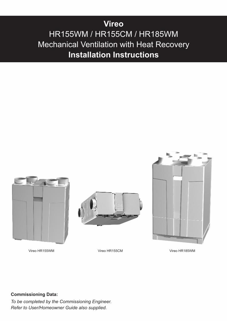
Vireo HR155WM / HR155CM / HR185WM Mechanical Ventilation with Heat Recovery Installation Instructions Commissioning Data: To be completed by the Commissioning Engineer. Refer to User/Homeowner Guide also supplied. Vireo HR155WM Vireo HR155CM Vireo HR185WM
Transcript of HR155WM / HR155CM / HR185WM Mechanical Ventilation with ... · Vireo HR155WM / HR155CM / HR185WM...
VireoHR155WM / HR155CM / HR185WM
Mechanical Ventilation with Heat RecoveryInstallation Instructions
Commissioning Data: To be completed by the Commissioning Engineer. Refer to User/Homeowner Guide also supplied.
Vireo HR155WM Vireo HR155CM Vireo HR185WM

Contents
2
Page
1.0 General Description / Physical Specifications ....................................... 3 - 4
2.0 Installation Instructions ........................................................................... 5
General Preparation.................................................................................... 5
Positioning .................................................................................................. 5
Configuration............................................................................................... 6
Mounting ..................................................................................................... 7
Access Dimension for Maintenance............................................................ 9
Condensate Drain ....................................................................................... 10
DuctingGuidelines ...................................................................................... 11
Electrical ..................................................................................................... 12
Wiring The Unit ........................................................................................... 13
Connecting to the BMS ............................................................................... 13
3.0 On-Site Commissioning ........................................................................... 16
4.0 Declaration of Performance (DOP) ............................................................. 19
5.0 Guarantee .................................................................................................. 23
Vireo HR155WM Vireo HR155CM Vireo HR185WM
1.0 General Description / Physical Specifications
3
1.1 Overview
1.1.1 The Vireo HR155WM / HR155CM / HR185WM is a ventilation system designed to provide improved indoor airqualityindwellings.Asawholehousesystem,theunitcontinuouslyextractsairfromthenon-habitableroomsandsuppliesfresh,filteredairtohabitablerooms.Heatthatisrecoveredfromtheairdrawnfromthebathroomsandkitchenispassedthroughaheatexchangerandtheheatthatisrecoveredistransferred,totemperthesupplyairinhabitableroomstoprovideacomfortableindoorenvironment.
1.1.2 Aboostspeedfacilityisprovidedtoincreasetheventilationrate,e.g.whencookingorshowering,providingacomfortableindoorenvironment.AGS2SwitchLiveboostswitchoraGRC1boostandalertcontrollercanbeusedtoprovidethisoperation (See Section 2.8.5 Electrical).
1.1.3 ThisproductfeaturesonPCDBasahighefficiencyversionandpartoftheprocessrequirestheInstallationChecklistforMVHRproductstobecompletedandsubmittedtobuildingcontrol,availableat www.ncm-pcdb.org.ukalongwithallotherrelevantpaperwork.
1.1.4 Recordsheetsforcommissioninginformationareprovided,pleaserefertosection6oftheUser/HomeownerGuidealsosuppliedwiththeVireoHeatRecoveryUnit.
1.1.5 Ancillary Items Required
Vireo HR155WM / HR155CM Vireo HR185WM125mmDucting(rectangularductingcanbeused,where appropriate)
150mmDucting(rectangularductingcanbeused,where appropriate)
GS2Hardwiredswitchprovidingswitchingbetweenlow and high (option)
GS2Hardwiredswitchprovidingswitchingbetweenlow and high (option)
GRC1Hardwiredboostandsystemstatuscontroller,switchingbetweenlowandhigh(option)
GRC1Hardwiredboostandsystemstatuscontroller,switchingbetweenlowandhigh(option)
1.1.6 Packaging includes:-
1xHeatRecoveryUnit 1xWallFixingBracket(VireoHR155WM/HR185WM)or
2xCeilingFixingBracket(VireoHR155CM) 1xInstallationInstructions 1xUser/HomeownerGuide
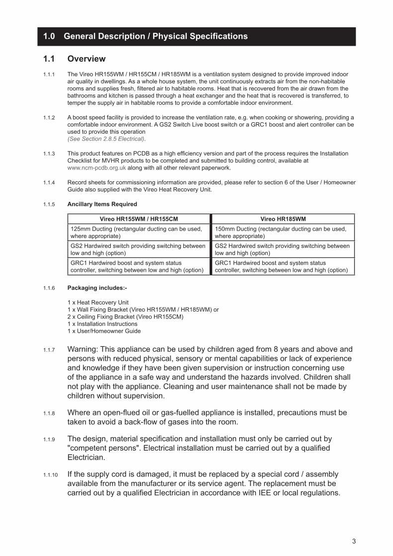
1.1.7 Warning: Thisappliancecanbeusedbychildrenagedfrom8yearsandaboveandpersonswithreducedphysical,sensoryormentalcapabilitiesorlackofexperienceandknowledgeiftheyhavebeengivensupervisionorinstructionconcerninguseoftheapplianceinasafewayandunderstandthehazardsinvolved.Childrenshallnotplaywiththeappliance.Cleaningandusermaintenanceshallnotbemadebychildrenwithoutsupervision.
1.1.8 Whereanopen-fluedoilorgas-fuelledapplianceisinstalled,precautionsmustbetakentoavoidaback-flowofgasesintotheroom.
1.1.9 Thedesign,materialspecificationandinstallationmustonlybecarriedoutby"competentpersons".ElectricalinstallationmustbecarriedoutbyaqualifiedElectrician.
1.1.10 Ifthesupplycordisdamaged,itmustbereplacedbyaspecialcord/assemblyavailablefromthemanufactureroritsserviceagent.ThereplacementmustbecarriedoutbyaqualifiedElectricianinaccordancewithIEEorlocalregulations.
4
1.1.11 Observeappropriatesafetyprecautionsifworkingonstepsorladders.Weareyeprotectionwhenbreakingoutwallsorwindowmaterials
1.1.12 Todisassembletheunit,disconnectfrommainssupplyanduseascrewdrivertosegregatetheelectroniccomponentsandmotorsfromtheplastichousing.Disposeitems in accordance with WEEE.
1.1.13 WEEE Statement Thisproductmaynotbetreatedashouseholdwaste.Insteaditshouldbehandedtoanappropriatecollectionpointfortherecyclingofelectricalandelectronicequipment.
For more detailed information about the recycling of this product, please contact your local council office or your household waste disposal service.
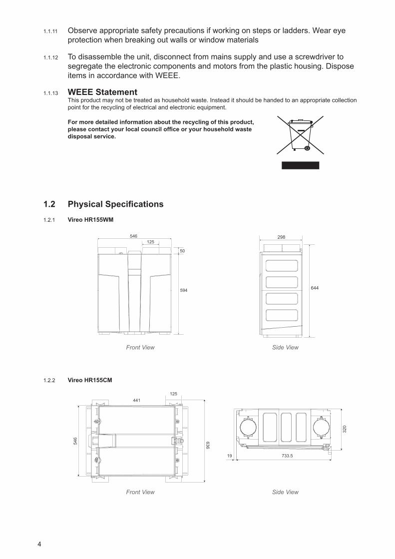
1.2 Physical Specifications 1.2.1 Vireo HR155WM
546
Vireo HR155WM front
125
50
594
Vireo HR155WM side
298
644
Front View Side View
1.2.2 Vireo HR155CM
546 636
125441
Vireo HR155CM front
733.5 19
320
Vireo HR155CM side
Front View Side View

2.0 Installation Instructions
2.1 General Preparation 2.1.1 TheVireoHR155WM/HR155CMunitissuppliedwith4x125mmØspigots.
• 125mmductingwithconnectorscanbeused(see Ancillary Section page 3) to provide performance levelsrequiredforcompliancewithBuildingRegulations.
2.1.2 TheVireoHR185WMunitissuppliedwith4x150mmØspigots.
• 150mmductingwithconnectorscanbeused(see Ancillary Section page 3) to provide performance levelsrequiredforcompliancewithBuildingRegulations.
2.1.3 InstallationoftheunitshouldbeinaccordancewiththecurrenteditionsofBuildingRegulations,NHBCComplianceGuideandBS7671:IEEWiringRegulations.
2.1.4 Thedesign,materialspecificationandinstallationmustonlybecarriedoutby"competentpersons".ElectricalinstallationmustbecarriedoutbyaqualifiedElectrician.
2.1.5 IMPORTANT NOTE: Gases from fuel-burning equipment must not be drawn into any living areas. If any room, where air is extracted, contains a fuel-burning appliance such as a central heating boiler, then either of the following should be undertaken:
• Thefluemustbeoftheroomsealedorbalancedfluetypeor;• Allowancemustbemadeforanadequatesupplyofairintotheroom.
2.2 Positioning 2.2.1 TheVireoHR155WM/HR185WMunitmustbeinstalledverticallyandcanbeeitherwallorfloormountedto
enableeffectivecondensatedrainageineitherakitchen/servicecupboardorsecuredtoaverticalstructureintheloftspace.Iflocatedwithinacoldspace,itisrecommendedthatthebottomoftheunitisinsulatedtopreventfreezingaroundthecondensateconnection.Ductspigotsmustbeuprightattopofunit.
2.2.2 TheVireoHR155CMunitmustbeinstalledhorizontallywiththefixingbracketsprovided.Theunitisnotintendedforinstallationwithinautilityroom.
5
1.2.3 Vireo HR185WM
839
60
550
Vireo HR185WM front
899
555
150
Vireo HR185WM side
Front View Side View

6
2.2.3 Itisnotadvisabletoinstalltheunitdirectlyaboveabedroomorlivingroomceiling,orinanareathatispartofalivingareaorbedroom.
2.2.4 Considerationmustbegiventoallowforadequateaccessforservicing,maintenanceandanyfaultdiagnostics (See Section 2.5 Access for Maintenance).
2.2.5 TheunitcanbeconfiguredforrightandlefthandinstallationatatouchofabuttonbyfollowingthestepswithintheCommissioningWizard(See Section 3.1.4 Commissioning Wizard)anddoesnotrequireanyinternal changes. (See Figures overleaf for ducting configuration).
2.3 Configuration Note: Tochangethehandingoftheunit, followthesimplestepswithintheCommissioningWizard
(See Section 3.0).Automaticallydoneforyouviasoftware.
2.3.1 Vireo HR155WM
Right Hand (factory setting)
INTAKE
EXHAUST
SUPPLY
EXTRACT
Left Hand
EXTRACT
SUPPLY
EXHAUST
INTAKE
Right Hand (factory setting) Left Hand
2.3.2 Vireo HR155CM
Right Hand (factory setting)
INTAKE EXTRACT
SUPPLYEXHAUST
Left Hand
EXTRACT INTAKE
EXHAUSTSUPPLY
Right Hand (factory setting) Left Hand
2.3.3 Vireo HR185WM
INTAKE
SUPPLY
EXHAUSTEXTRACT
Right Hand (factory setting)
EXTRACT
EXHAUST
SUPPLYINTAKE
Left HandRight Hand (factory setting) Left Hand

7
2.4 Mounting 2.4.1 TheVireoHR155WM/HR185WMunitissuppliedwithonewallfixingbracket.Thebracketisalongstripand
hastwoadjustablefixingpointslocatedattheendofthebracket.Screwsandfixingsnotsupplied.
2.4.2 Proceedtoalignthewallbrackettakingintoaccounttheavailablewallspacetomounttheunit,ensuringthatthewallcansupport20kg(VireoHR155WM)and30kg(VireoHR185WM).
2.4.3 Useaspiritleveltoassistmountingandlevellingthebracket.Securelyfixbrackettowallusing suitablefixings.e‘V’slotslocatedtopandbottomofbrackettomar
2.4.4 Theunitfixestothewallbracketbyslottingthebracketattachedtothebackoftheunitandhooking into place.
Fixing Bracket
Note:
• Fixing Bracket height will be critical in kitchen cupboard.
• There should be no movement once correctly located and the filters should be accessible from easily removing the panels on the front of the unit. (See Section 4.1.8, and 4.2.0, Homeowner Guide).
2.4.5 TheVireoHR155CMunitissuppliedwithtwoadjustableceilingfixingbrackets.Eachbracketisalongstripandhasfourfixingpointslocatedatequalintervals.Itisrecommendedthatsixscrewsperbracketareusedtosecuretheunit.Screwsandfixingsarenotsupplied.
WARNING: Ensure that the ceiling board can support 20kg (Vireo HR155CM) or reinforcement may be required.
2.4.6 Proceedtoalignandsecurethefirstceilingbrackettakingintoaccounttheavailableceilingspacetomounttheunit.Locatesecondbracketposition(See Figure 1) andlooselyfitfourscrewswithineachslotattheinnernearsidepoint.Thiswillallowthebrackettobeslottedinwardstosecuretheunit.
640mm
Loosely Fix Screws Securely Fix Screws
12
Figure 1

2.4.7 Theunitfixestotheceilingbracketbyslottingthebracketattachedtothebackoftheunitandslidingintoplace.Firstensureconnectionisachievedonthe“securely”fixedbracket(See Figure 2) andpushunituptoceiling, slide“loosely”fixedbrackettoconnectwiththebracketonthebackoftheunit(See Figure 3).
Securely locatebrackets together
Figure 2
Figure 3
2.4.8 Tightenloosescrewsuntiltheunitissecurelyfitted(See Figure 4),addanadditionaltwoscrewstotheoutsideslots.ScrewpointsforbothbracketsareshowninFigure 5.
Figure 4
Figure 5
Note:
• There should be no movement once correctly located and the filters should be accessible from easily removing the panels on the front of the unit (See Section 4.1.9, Homeowner Guide).
8
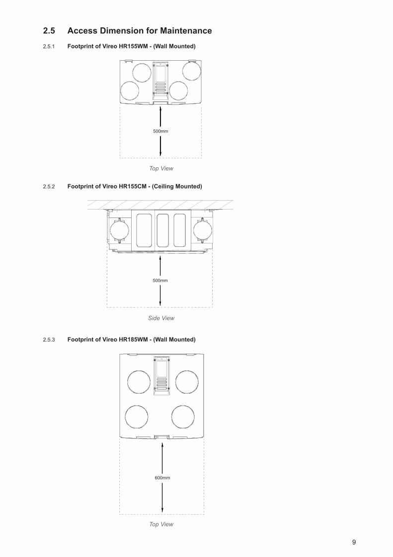
2.5 Access Dimension for Maintenance 2.5.1 Footprint of Vireo HR155WM - (Wall Mounted)
500mm
HR155WM
Top View
2.5.2 Footprint of Vireo HR155CM - (Ceiling Mounted)
500mm
HR155CM
Side View
2.5.3 Footprint of Vireo HR185WM - (Wall Mounted)
600mm
HR185WM
Top View
9
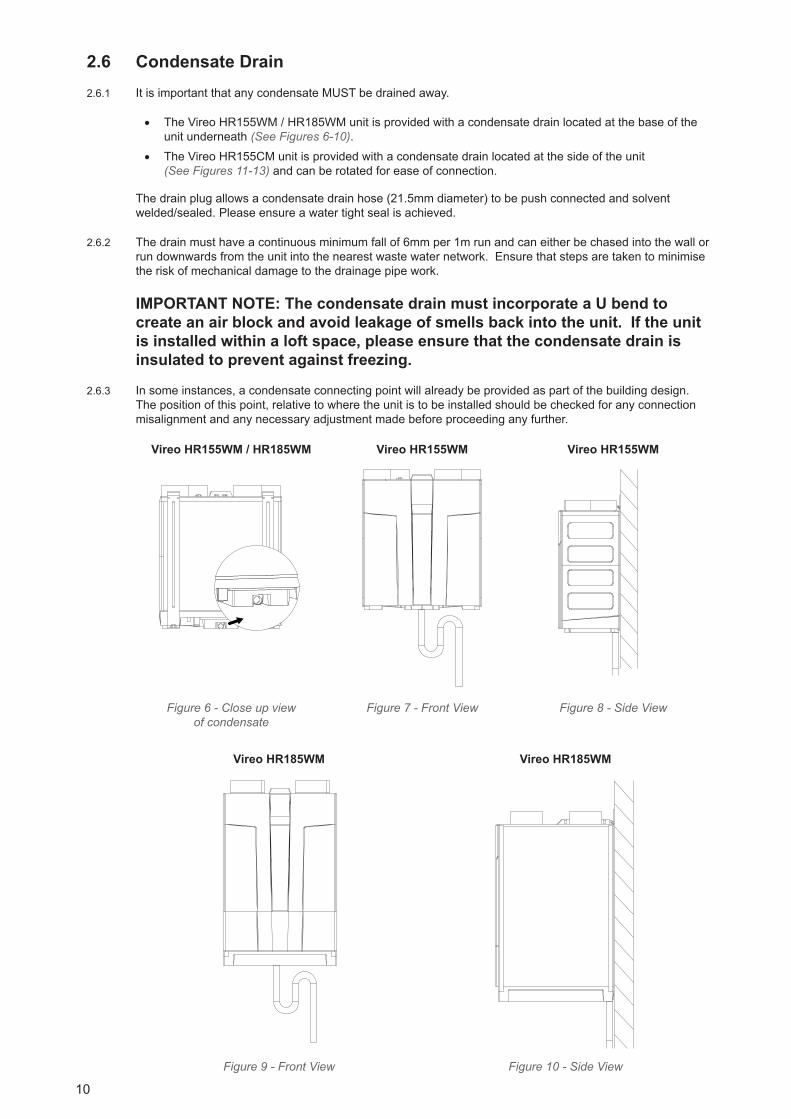
2.6 Condensate Drain 2.6.1 ItisimportantthatanycondensateMUSTbedrainedaway.
• TheVireoHR155WM/HR185WMunitisprovidedwithacondensatedrainlocatedatthebaseoftheunitunderneath(See Figures 6-10).
• TheVireoHR155CMunitisprovidedwithacondensatedrainlocatedatthesideoftheunit (See Figures 11-13) andcanberotatedforeaseofconnection.
Thedrainplugallowsacondensatedrainhose(21.5mmdiameter)tobepushconnectedandsolvent welded/sealed.Pleaseensureawatertightsealisachieved.
2.6.2 Thedrainmusthaveacontinuousminimumfallof6mmper1mrunandcaneitherbechasedintothewallorrundownwardsfromtheunitintothenearestwastewaternetwork.Ensurethatstepsaretakentominimisetheriskofmechanicaldamagetothedrainagepipework.
IMPORTANT NOTE: The condensate drain must incorporate a U bend to create an air block and avoid leakage of smells back into the unit. If the unit is installed within a loft space, please ensure that the condensate drain is insulated to prevent against freezing.
2.6.3 Insomeinstances,acondensateconnectingpointwillalreadybeprovidedaspartofthebuildingdesign.Thepositionofthispoint,relativetowheretheunitistobeinstalledshouldbecheckedforanyconnectionmisalignmentandanynecessaryadjustmentmadebeforeproceedinganyfurther.
Vireo HR155WM / HR185WM Vireo HR155WM Vireo HR155WMHR155WM/185WM Condensate connection
HR155WM HR155WM
Figure 6 - Close up view of condensate
Figure 7 - Front View Figure 8 - Side View
Vireo HR185WM HR185WM Vireo HR185WM HR185WM
Figure 9 - Front View Figure 10 - Side View
10

Vireo HR155CM Vireo HR155CM Vireo HR155CMHR155CM FRONT HR155CM SIDE
Figure 11 - Close up view of condensate
Figure 12 - Front View Figure 13 - Side View
2.7 Ducting Guidelines 2.7.1 Pleaserefertodesigndrawingsforproposedductinglayout.
2.7.2 Fourspigotsareprovidedforconnectionoftheducting;
• Vireo HR155WM / HR155CM - 125mm nominal diameter
• Vireo HR185WM - 150mm nominal diameter.
Ductworkshouldbesecurelyconnectedtospigots.Failuretodothiswillcauseunnecessaryairleakageandimpairperformance.Ductingmustbeconnectedtoallfourspigotsaccordingtorightorlefthandconfiguration(See Section 2.3 for Configuration).
2.7.3 Whereductsareexposedinunheatedareas,suchasroofspaces,theymustbeinsulatedwithatleast25mmofinsulation.
2.7.4 Ifapplicable,FireDampersMUST BE FITTEDinaccordancewithPartBoftheBuildingRegulations.
2.7.5 Rigid Ducting
• Installusingtheleastnumberoffittingstominimiseresistancetoairflow.
• Wherepossible,finalconnectiontogrillesandunitshouldbemadewithaflexibleconnection.
• Mechanicallyfixductsusingmetaljubileeclipsandappropriatenon-hardeningsealantforairtightness.
WARNING: Do not use screws for connection and ensure jubilee clips are not over tightened.
2.7.6 Flexible Ducting
• Ensureductinglengthsarekepttoaminimumandductingispulledtautsothatitissmooth and straight.
• Wherebendsarenecessaryandwhereductingisruninrestrictedareas,ensuretheductingis notcrushed.
• Mechanicallyfixductsusingmetaljubileeclipsandtapesealforairtightness.
WARNING: Should be in accordance with Building Regulations.
11
2.7.7 Theintakefreshairshouldbedirectlyfromtheoutside.
• Ifdrawnthroughawall,anexternalgrilleshouldbefitted.
• Ifdrawnthrougharoof,arecognisedroofterminalshouldbefitted.
• Roofterminaltohaveaminimumequivalentfreeareaof10,000mm2.
2.7.8 Theexhaustairmustexittotheoutsidethroughawallorroofandmustbeprotectedbyawallgrilleorrecognised roof terminal.
• Roofterminaltohaveaminimumequivalentfreeareaof10,000mm2.
2.7.9 Intakeandexhaustpipesshouldbeinstalledatleast1maparttoavoidthecrosscontaminationofairflows.
2.8 Electrical
2.8.1 WARNING: The appliance MUST be earthed. All wiring must conform to BS7671: IEE Wiring Regulations.
2.8.2 TheinstallationmustbecarriedoutbyaqualifiedElectrician.
2.8.3 Allunitsaresuitablefora230V~50Hzsinglephasesupplyfusedat3A.
2.8.4 Atriple-poleswitchhavingaminimumcontactseparationof3.0mmmustbeusedtoprovideisolationfor theunit.
2.8.5 TherecommendedswitchesforusewiththisproductaretheGreenwoodAirvac;
GS2 - Optional 2-position hardwired switch GRC1-Optionalboost+systemstatushardwiredremoteswitch
(See Figure 14 for wiring diagram)
Controller Switch Type SpeedsGS2 2-positionrocker Low(I)High(II)GRC1 Singlepushbutton Low(I)High(II)
GS2 GRC1
Note: The unit may also be wired to a Building Management System (BMS) (See Section 2.9.1 for wiring details).
2.8.6 Thecontrollersmustnotbemountedinabathroomorabove/closerthan1metertoacookerwhereitcouldbeaffectedbyexcessiveheatormoisture.
2.8.7 TheVireounitissuppliedwithapre-wiredmainsflexiblecord-PVCsheathed,4-coregreen/yellow,blue,brown&black.Size0.75mm2.
2.8.8 'If the supply cord is damaged, it must be replaced by a special cord/assembly available from the manufacturer or its service agent. The replacement must be carried out by a qualified Electrician in accordance with IEE or local regulations'.
12

2.9 Wiring the Unit to a Standard 2-Position Switch Usingflyingleadprovided,wireasperspecificationdiagram.ExternalwiringforVireoforcontinuous
operationonlowspeedandboostoperationviaGreenwood'sGS22-positionswitch(optional).
Wiring
ENN
L LL1
Triple-poleIsolatingSwitch
E
Light Switch
Light
Green/Yellow
Blue
Brown
Black
3A Fuse
Connector box for mains voltage cabling (Not supplied)
Flying lead from Vireo 0.75mm2
Figure 14 - Wiring Specification
2.9.1 Wiring Enhanced Control Options via the Building Management System (BMS)
2.9.2 TowireintototheBMSconnectorwithintheVireounit,firstremovetheelectricalwiringcoverasper Fig.15-17belowthenlocatetheBMSconnectoronthePCB.
Vireo HR155WM Vireo HR185WM Vireo HR155CM
HR155WMSupply cord
HR185WM HR155CM
Figure 15 - Top View Figure 16 - Top View Figure 17 - Top View
Warning: Ensure that you use the cable grommet provided when connecting to the BMS to protect against potential water ingress. Take care that the gasket seal underneath the PCB cover is not disturbed.
13
PCB CLOSEUP
BMSConnector
Pre-wiredsupply cordconnector
DO NOTDISCONNECT
Cable grommetfor BMSconnection
Pre-wiredsupply cordnot shown

2.9.3 Usingsuitablysizedcabling,theBMSterminalblockcanberemovedforeasierwiring.
• Pins1-2allowsaremoteswitchtobeusedforaboostswitch(Note:NOTFORMAINSWIRING).
• Pins2-3tobeusedexclusivelywithaGRC1controller.
• Pins4,5&6allowsforremotefaultindication.Relaywillbeenergisedupondetectionofafault.
Uponcompletionofwiring,carefullypushfitBMSterminalblockbackontoPCB.
Pin Function Connection to External Circuit1 Boost ForadditionalsensorstoHigh2 Ground 0V 3 Remote Connecting to a GRC1 controller (option)4 N/C Volt-Freenormallyclosedcontact5 N/O Volt-Freenormallyopencontact6 Common Relay common
Figure 18 - Close-up of PCB with BMS connection points
Figure 19 - GRC1 Controller Figure 20 - BMS Wiring Diagram
Note:OnlyoneGRC1boostandstatuscontrollercanbeinstalledwiththeVireounit.Additionalboostactuationshouldbeviaeither'switch-live'orstandardhardwired2-positionswitches.
1 2 3 4 5 6
14
1 2 6 5 4 3
N/C N/O COM
ELECTRICAL CONNECTION / TERMINAL DIAGRAM
BOOST GND REM
GRC1
GREENWOOD REMOTE CONTROLLER(GRC1 - Option)
VOLT FREE CONTACTSGIVING FAULT
IDENTIFICATION
}
REM
G
ND
BATHROOM SW.(Volt free contact)NOT RATED FOR
MAINS SWITCHING
BMS CONNECTOR
RL1 - RELAY
1 2 6 5 4 3
N/C N/O COM BOOST GND REM
Vireo UnitBMS Connector
2 core cable, 0.5mm Max.(up to 15 metres)
15
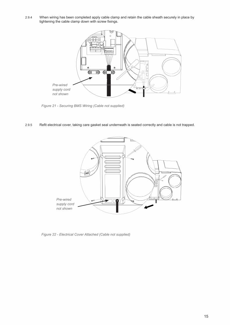
2.9.4 Whenwiringhasbeencompletedapplycableclampandretainthecablesheathsecurelyinplacebytighteningthecableclampdownwithscrewfixings.
1 2 3 4 5
1 2 3 4 5
Figure 21 - Securing BMS Wiring (Cable not supplied)
2.9.5 Refitelectricalcover,takingcaregasketsealunderneathisseatedcorrectlyandcableisnottrapped.
Figure 22 - Electrical Cover Attached (Cable not supplied)
Pre-wiredsupply cordnot shown
Pre-wiredsupply cordnot shown

16
3.0 On-Site Commissioning
3.1.1 Thissectioncoversset-up,configurationoftheunitforinstallationandalteringpre-setfactorysettings. ForinstructionsonhowtooperatetheLCDdisplayusermenu,maintenanceoptionsandindicatorwarninginformation,pleaserefertotheUser/HomeownerGuide.
3.1.2 Oncethewiringconnectionshavebeenchecked,switchthemainssupplyonandcheckthatthesystemisoperatingcorrectly.Liftcoverofcommissioningwizardlocatedatthetopoftheunit.Uponconnectionofelectricalsupply,thecommissioningwizardwillautomaticallyturnon(See Section 3.1.4).
3.1.3 Integral LCD Display
Frost ProtectionLED
Service/Fault LED
SummerByPass
LED
Control Information Panel
ControlButton
SETUP COMMISSIONING WIZARD
Belowareexamples/explanationsofwhatyouwouldseethroughtheCommissioningWizard.
P
SETUP COMMISSIONING WIZARD
O R T C O N F I G :
< R H >
Example 1: Function selection screen
Top line - function / statement.
Bottom line - flashing cursor indicating nextaction to be reviewed/changed.
P O R T C O N F I G :
< R H > >dwf> c kab
Example 2: Re-confirmation screen
Top line - function / statement.
Bottom line - three selectable functions always come into screen with fwd flashing.Option to move forward towards completion orback to re-set function.
S E T U P C O M P L E T E
>i txe> c kab
Example 3: No editable variable in middle only ever seen as last step in the wizard
Top line - function / statement.
Bottom line - two selectable functions only found at the end of the wizard.Selection of exit will confirm all wizardconfiguration settings.
Below are examples/explanations of what you would see through the Commissioning Wizard.
17
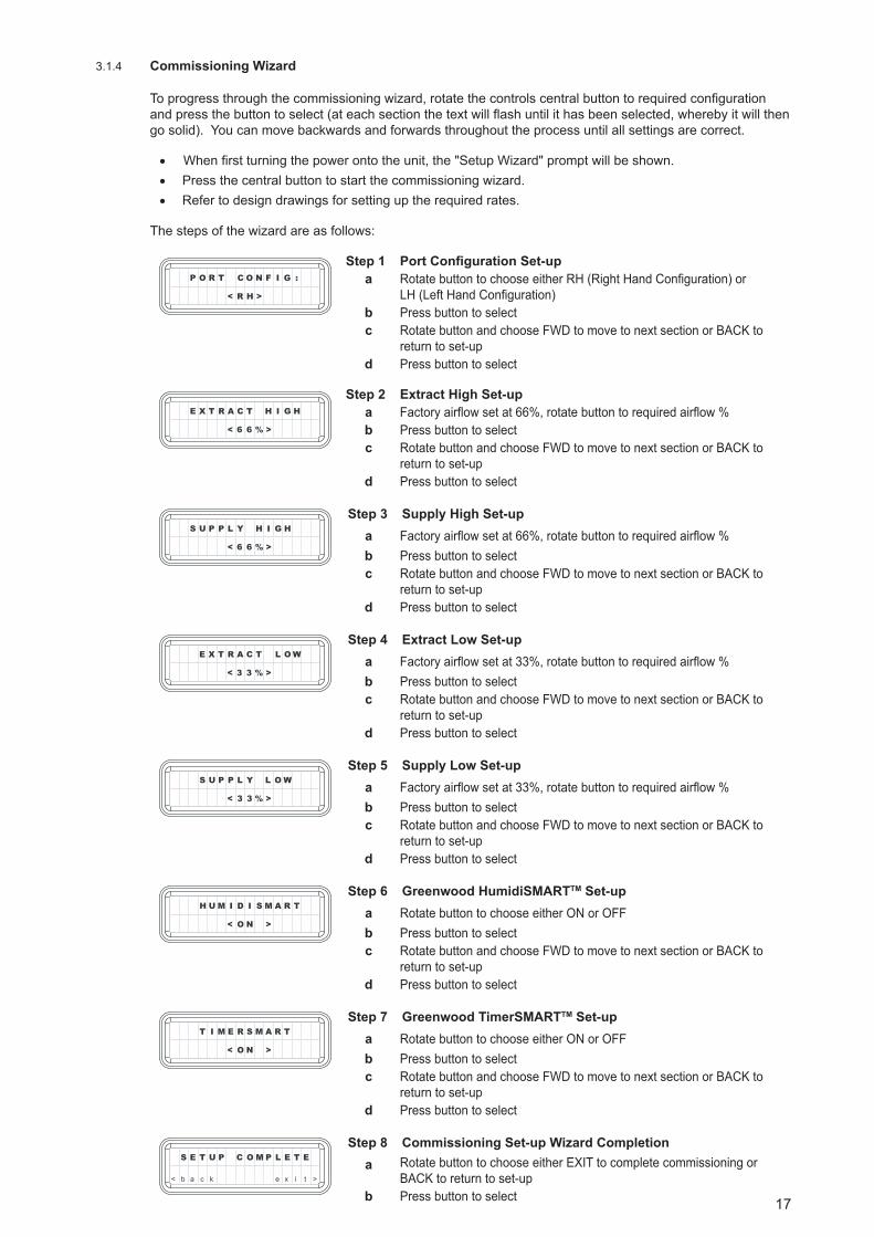
3.1.4 Commissioning Wizard
Toprogressthroughthecommissioningwizard,rotatethecontrolscentralbuttontorequiredconfigurationandpressthebuttontoselect(ateachsectionthetextwillflashuntilithasbeenselected,wherebyitwillthengosolid).Youcanmovebackwardsandforwardsthroughouttheprocessuntilallsettingsarecorrect.
• Whenfirstturningthepowerontotheunit,the"SetupWizard"promptwillbeshown.
• Pressthecentralbuttontostartthecommissioningwizard.
• Refertodesigndrawingsforsettinguptherequiredrates.
Thestepsofthewizardareasfollows:
P O R T C O N F I G :
< R H >
Step 1 Port Configuration Set-upa RotatebuttontochooseeitherRH(RightHandConfiguration)or
LH(LeftHandConfiguration)b Pressbuttontoselectc RotatebuttonandchooseFWDtomovetonextsectionorBACKto
returntoset-upd Pressbuttontoselect
E X T R A C T H I G H
< 6 6 % >
Step 2 Extract High Set-upa Factoryairflowsetat66%,rotatebuttontorequiredairflow%b Pressbuttontoselectc RotatebuttonandchooseFWDtomovetonextsectionorBACKto
returntoset-upd Pressbuttontoselect
S U P P L Y H I G H
< 6 6 % >
Step 3 Supply High Set-upa Factoryairflowsetat66%,rotatebuttontorequiredairflow%b Pressbuttontoselectc RotatebuttonandchooseFWDtomovetonextsectionorBACKto
returntoset-upd Pressbuttontoselect
E X T R A C T L O W
< 3 3 % >
Step 4 Extract Low Set-upa Factoryairflowsetat33%,rotatebuttontorequiredairflow%b Pressbuttontoselectc RotatebuttonandchooseFWDtomovetonextsectionorBACKto
returntoset-upd Pressbuttontoselect
S U P P L Y L O W
< 3 3 % >
Step 5 Supply Low Set-upa Factoryairflowsetat33%,rotatebuttontorequiredairflow%b Pressbuttontoselectc RotatebuttonandchooseFWDtomovetonextsectionorBACKto
returntoset-upd Pressbuttontoselect
H U M I D I S M A R T
< O N >
Step 6 Greenwood HumidiSMARTTM Set-upa RotatebuttontochooseeitherONorOFFb Pressbuttontoselectc RotatebuttonandchooseFWDtomovetonextsectionorBACKto
returntoset-upd Pressbuttontoselect
T I M E R S M A R T
< O N >
Step 7 Greenwood TimerSMARTTM Set-upa RotatebuttontochooseeitherONorOFFb Pressbuttontoselectc RotatebuttonandchooseFWDtomovetonextsectionorBACKto
returntoset-upd Pressbuttontoselect
S E T U P C O M P L E T E
< b a c k e x i t >
Step 8 Commissioning Set-up Wizard Completiona RotatebuttontochooseeitherEXITtocompletecommissioningor
BACKtoreturntoset-upb Pressbuttontoselect
18
3.1.5 Valve Set-up
• Switchtheunittothehighestoperatingposition.
• Closeexternalwindowsanddoors.
• Withthesystemoperatinginhighmode,proceedtoopentheextractvalvestotheirmaximum.
• Measurethetotalairvolumeattheextractvalves.
• Regulatetheextractvalvestotherequiredflowperroom.
• Switchtheunittolowspeedtoconfirmdesiredextractrateisachieved. Itshouldnormallynotbenecessarytoadjusttheextractvalvesfurther.
• Repeattestsforsupplyairvalves.
3.1.6 Oncetheunitiscommissionedcheckthatthesystemisoperatingcorrectlybyturningthehardwiredswitchtothedifferingsettings,i.e.theGS2switchorGRC1controllerwillactivatetheunitbetweenlowandhighspeedsettings.
• Performancelevelscanbeverifiedatbothextractandsupplyairvalvesusinganappropriatemethodsuchasarotatingvaneanemometerandairconekit.
• RecordairflowratesforroomextractandsupplyairvalvesforlowandhighspeedswithintheseparateUser/HomeownerguidethatshouldbeincorporatedintotheHomeInformationPackforthehomeownertokeep.
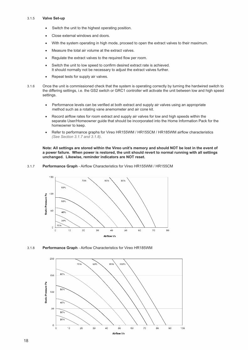
• RefertoperformancegraphsforVireoHR155WM/HR155CM/HR185WMairflowcharacteristics(See Section 3.1.7 and 3.1.8).
Note: All settings are stored within the Vireo unit’s memory and should NOT be lost in the event of a power failure. When power is restored, the unit should revert to normal running with all settings unchanged. Likewise, reminder indicators are NOT reset.
3.1.7 Performance Graph-AirflowCharacteristicsforVireoHR155WM/HR155CM
3.1.8 Performance Graph-AirflowCharacteristicsforVireoHR185WM
19
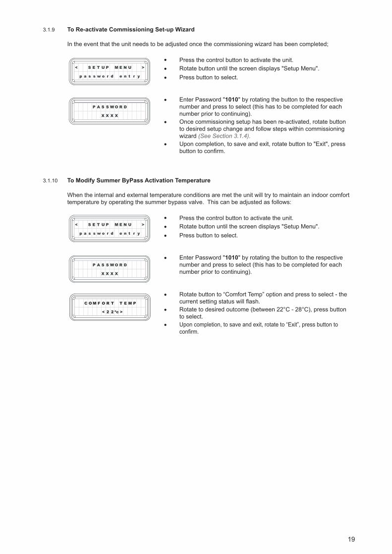
3.1.9 To Re-activate Commissioning Set-up Wizard
Intheeventthattheunitneedstobeadjustedoncethecommissioningwizardhasbeencompleted;
S E T U P M E N U ><
p a s s w o r d e n t r y
P A S S W O R D
X X X X
• Pressthecontrolbuttontoactivatetheunit.• Rotatebuttonuntilthescreendisplays"SetupMenu".
• Pressbuttontoselect.
• Enter Password "1010"byrotatingthebuttontotherespectivenumberandpresstoselect(thishastobecompletedforeachnumberpriortocontinuing).
• Oncecommissioningsetuphasbeenre-activated,rotatebuttontodesiredsetupchangeandfollowstepswithincommissioningwizard(See Section 3.1.4).
• Uponcompletion,tosaveandexit,rotatebuttonto"Exit",pressbuttontoconfirm.
3.1.10 To Modify Summer ByPass Activation Temperature
Whentheinternalandexternaltemperatureconditionsaremettheunitwilltrytomaintainanindoorcomforttemperaturebyoperatingthesummerbypassvalve.Thiscanbeadjustedasfollows:
S E T U P M E N U ><
p a s s w o r d e n t r y
P A S S W O R D
X X X X
• Pressthecontrolbuttontoactivatetheunit.• Rotatebuttonuntilthescreendisplays"SetupMenu".
• Pressbuttontoselect.
• Enter Password "1010"byrotatingthebuttontotherespectivenumberandpresstoselect(thishastobecompletedforeachnumberpriortocontinuing).
• Rotatebuttonto“ComfortTemp”optionandpresstoselect-thecurrentsettingstatuswillflash.
• Rotatetodesiredoutcome(between22°C-28°C),pressbuttonto select.
• Uponcompletion,tosaveandexit,rotateto“Exit”,pressbuttontoconfirm.
M F O R T T E
< 2 2 ºc >
OC M P
Supplier Name or Trade Mark
Supplier Model Identifier and Options Installed
SEC in [kWh/(m2a)] for Each Climate(Cold, Average, Warm)
SEC Class(Cold, Average, Warm)
Declared Typology
Type of Motor Drive Installed
Type of Heat Recovery1
Heat Recovery Efficiency2
Maximum Flow Rate in (m3/h) / (l/s)3
Electric Power Input at Maximum Flow Rate (W)4
Sound Power Level (LWA) in dB(A))5
Reference Flow Rate in (m3/h) / l/s)6
Reference Pressure Difference
SPI in [W/(m3/h)]7
Control Factor and Typology
Declared Maximum Internal and External Leakage (%)8
Position and Description of Visual Filter Warning
Internet Address for Preassembly / Disassembly Instructions
AEC (kWh electricity/a) for Each Climate(Cold, Average, Warm)
AHS (kWh electricity/a) for Each Climate(Cold, Average, Warm)
Greenwood Airvac
Manual Control(via manual switch)
-73.5 -35.0 -10.4
A+ A E
Bidirectional
Variable Speed
Recuperative
90%
279 / 77
154
50
191 / 53
50
0.33
1
Internal: 2.7%External: 2.9%
Details withinHomeowner Guide
www.greenwood.co.uk
16.2 10.8 10.3
89.6 45.8 20.7
Greenwood Airvac
Local Demand Control(with 2 or more sensors)
-81.6 -42.1 -16.9
A+ A+ E
Bidirectional
Variable Speed
Recuperative
90%
279 / 77
154
50
191 / 53
50
0.33
0.65
Internal: 2.7%External: 2.9%
Details withinHomeowner Guide
www.greenwood.co.uk
10.2 4.8 4.4
91.8 46.9 21.2
Greenwood Airvac
Central Demand Control(with 1 sensor)
-77.3 -38.4 -13.5
A+ A E
Bidirectional
Variable Speed
Recuperative
90%
279 / 77
154
50
191 / 53
50
0.33
0.85
Internal: 2.7%External: 2.9%
Details withinHomeowner Guide
www.greenwood.co.uk
13.3 7.9 7.5
90.6 46.3 20.9
Greenwood Airvac
Clock Control(via 7 day timer control)
-74.8 -36.2 -11.5
A+ A E
Bidirectional
Variable Speed
Recuperative
90%
279 / 77
154
50
191 / 53
50
0.33
0.95
Internal: 2.7%External: 2.9%
Details withinHomeowner Guide
www.greenwood.co.uk
15.2 9.8 9.3
89.9 46.0 20.8
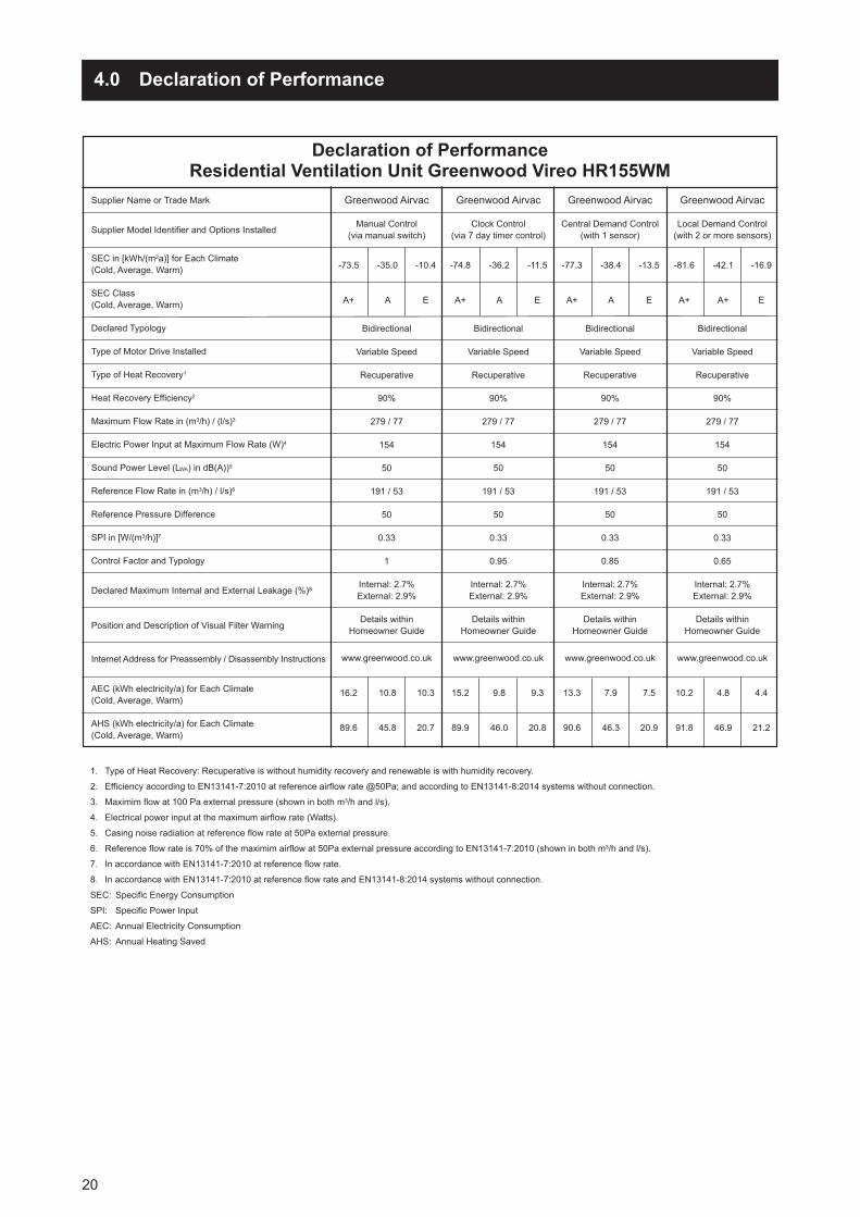
Declaration of PerformanceResidential Ventilation Unit Greenwood Vireo HR155WM
1. Type of Heat Recovery: Recuperative is without humidity recovery and renewable is with humidity recovery.2. Efficiency according to EN13141-7:2010 at reference airflow rate @50Pa; and according to EN13141-8:2014 systems without connection.3. Maximim flow at 100 Pa external pressure (shown in both m3/h and l/s).4. Electrical power input at the maximum airflow rate (Watts).5. Casing noise radiation at reference flow rate at 50Pa external pressure. 6. Reference flow rate is 70% of the maximim airflow at 50Pa external pressure according to EN13141-7:2010 (shown in both m3/h and l/s).7. In accordance with EN13141-7:2010 at reference flow rate.8. In accordance with EN13141-7:2010 at reference flow rate and EN13141-8:2014 systems without connection.SEC: Specific Energy ConsumptionSPI: Specific Power InputAEC: Annual Electricity ConsumptionAHS: Annual Heating Saved
20
4.0 Declaration of Performance
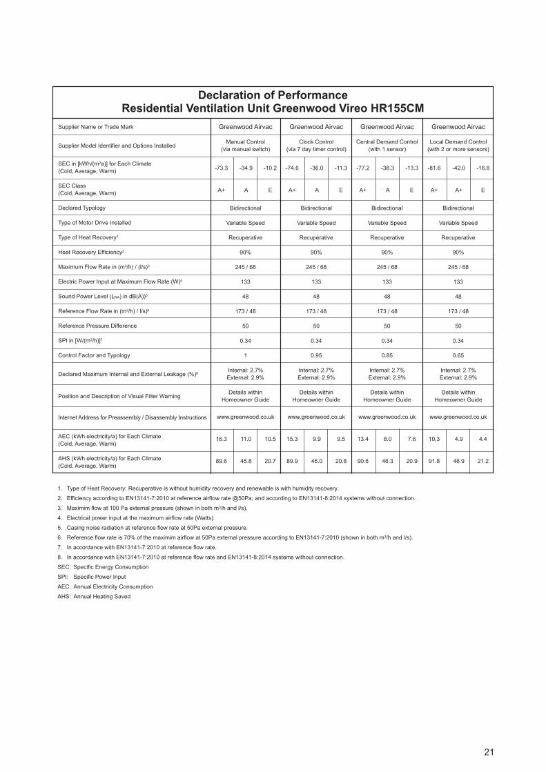
Supplier Name or Trade Mark
Supplier Model Identifier and Options Installed
SEC in [kWh/(m2a)] for Each Climate(Cold, Average, Warm)
SEC Class(Cold, Average, Warm)
Declared Typology
Type of Motor Drive Installed
Type of Heat Recovery1
Heat Recovery Efficiency2
Maximum Flow Rate in (m3/h) / (l/s)3
Electric Power Input at Maximum Flow Rate (W)4
Sound Power Level (LWA) in dB(A))5
Reference Flow Rate in (m3/h) / l/s)6
Reference Pressure Difference
SPI in [W/(m3/h)]7
Control Factor and Typology
Declared Maximum Internal and External Leakage (%)8
Position and Description of Visual Filter Warning
Internet Address for Preassembly / Disassembly Instructions
AEC (kWh electricity/a) for Each Climate(Cold, Average, Warm)
AHS (kWh electricity/a) for Each Climate(Cold, Average, Warm)
Greenwood Airvac
Manual Control(via manual switch)
-73.3 -34.9 -10.2
A+ A E
Bidirectional
Variable Speed
Recuperative
90%
245 / 68
133
48
173 / 48
50
0.34
1
Internal: 2.7%External: 2.9%
Details withinHomeowner Guide
www.greenwood.co.uk
16.3 11.0 10.5
89.6 45.8 20.7
Greenwood Airvac
Local Demand Control(with 2 or more sensors)
-81.6 -42.0 -16.8
A+ A+ E
Bidirectional
Variable Speed
Recuperative
90%
245 / 68
133
48
173 / 48
50
0.34
0.65
Internal: 2.7%External: 2.9%
Details withinHomeowner Guide
www.greenwood.co.uk
10.3 4.9 4.4
91.8 46.9 21.2
Greenwood Airvac
Central Demand Control(with 1 sensor)
-77.2 -38.3 -13.3
A+ A E
Bidirectional
Variable Speed
Recuperative
90%
245 / 68
133
48
173 / 48
50
0.34
0.85
Internal: 2.7%External: 2.9%
Details withinHomeowner Guide
www.greenwood.co.uk
13.4 8.0 7.6
90.6 46.3 20.9
Greenwood Airvac
Clock Control(via 7 day timer control)
-74.6 -36.0 -11.3
A+ A E
Bidirectional
Variable Speed
Recuperative
90%
245 / 68
133
48
173 / 48
50
0.34
0.95
Internal: 2.7%External: 2.9%
Details withinHomeowner Guide
www.greenwood.co.uk
15.3 9.9 9.5
89.9 46.0 20.8
Declaration of PerformanceResidential Ventilation Unit Greenwood Vireo HR155CM
1. Type of Heat Recovery: Recuperative is without humidity recovery and renewable is with humidity recovery.2. Efficiency according to EN13141-7:2010 at reference airflow rate @50Pa; and according to EN13141-8:2014 systems without connection.3. Maximim flow at 100 Pa external pressure (shown in both m3/h and l/s).4. Electrical power input at the maximum airflow rate (Watts).5. Casing noise radiation at reference flow rate at 50Pa external pressure. 6. Reference flow rate is 70% of the maximim airflow at 50Pa external pressure according to EN13141-7:2010 (shown in both m3/h and l/s).7. In accordance with EN13141-7:2010 at reference flow rate.8. In accordance with EN13141-7:2010 at reference flow rate and EN13141-8:2014 systems without connection.SEC: Specific Energy ConsumptionSPI: Specific Power InputAEC: Annual Electricity ConsumptionAHS: Annual Heating Saved
21
4.0 Declaration of Performance

Supplier Name or Trade Mark
Supplier Model Identifier and Options Installed
SEC in [kWh/(m2a)] for Each Climate(Cold, Average, Warm)
SEC Class(Cold, Average, Warm)
Declared Typology
Type of Motor Drive Installed
Type of Heat Recovery1
Heat Recovery Efficiency2
Maximum Flow Rate in (m3/h) / (l/s)3
Electric Power Input at Maximum Flow Rate (W)4
Sound Power Level (LWA) in dB(A))5
Reference Flow Rate in (m3/h) / l/s)6
Reference Pressure Difference
SPI in [W/(m3/h)]7
Control Factor and Typology
Declared Maximum Internal and External Leakage (%)8
Position and Description of Visual Filter Warning
Internet Address for Preassembly / Disassembly Instructions
AEC (kWh electricity/a) for Each Climate(Cold, Average, Warm)
AHS (kWh electricity/a) for Each Climate(Cold, Average, Warm)
Greenwood Airvac
Manual Control(via manual switch)
-75.5 -36.7 -11.9
A+ A E
Bidirectional
Variable Speed
Recuperative
91%
313 / 87
156
52
220 / 61
50
0.29
1
Internal: 2.4%External: 2.3%
Details withinHomeowner Guide
www.greenwood.co.uk
14.8 9.4 9.0
90.3 46.1 20.9
Greenwood Airvac
Local Demand Control(with 2 or more sensors)
-82.6 -42.9 -17.5
A+ A+ E
Bidirectional
Variable Speed
Recuperative
91%
313 / 87
156
52
220 / 61
50
0.29
0.65
Internal: 2.4%External: 2.3%
Details withinHomeowner Guide
www.greenwood.co.uk
9.6 4.2 3.8
92.2 47.1 21.3
Greenwood Airvac
Central Demand Control(with 1 sensor)
-78.8 -39.6 -14.6
A+ A E
Bidirectional
Variable Speed
Recuperative
91%
313 / 87
156
52
220 / 61
50
0.29
0.85
Internal: 2.4%External: 2.3%
Details withinHomeowner Guide
www.greenwood.co.uk
12.3 6.9 6.5
91.1 46.6 21.1
Greenwood Airvac
Clock Control(via 7 day timer control)
-76.6 -37.7 -12.8
A+ A E
Bidirectional
Variable Speed
Recuperative
91%
313 / 87
156
52
220 / 61
50
0.29
0.95
Internal: 2.4%External: 2.3%
Details withinHomeowner Guide
www.greenwood.co.uk
13.9 8.6 8.1
90.5 46.3 20.9
Declaration of PerformanceResidential Ventilation Unit Greenwood Vireo HR185WM
1. Type of Heat Recovery: Recuperative is without humidity recovery and renewable is with humidity recovery.2. Efficiency according to EN13141-7:2010 at reference airflow rate @50Pa; and according to EN13141-8:2014 systems without connection.3. Maximim flow at 100 Pa external pressure (shown in both m3/h and l/s).4. Electrical power input at the maximum airflow rate (Watts).5. Casing noise radiation at reference flow rate at 50Pa external pressure. 6. Reference flow rate is 70% of the maximim airflow at 50Pa external pressure according to EN13141-7:2010 (shown in both m3/h and l/s).7. In accordance with EN13141-7:2010 at reference flow rate.8. In accordance with EN13141-7:2010 at reference flow rate and EN13141-8:2014 systems without connection.SEC: Specific Energy ConsumptionSPI: Specific Power InputAEC: Annual Electricity ConsumptionAHS: Annual Heating Saved
22

5.0 The Guarantee Period
5.1.1 ThisGreenwoodproduct(VireoHR155WM/HR155CM/HR185WM)hasa2YearGuarantee.
5.1.2 Thisdoesnotaffectyourstatutoryrights.
5.1.3 Fulldetailsavailableonrequestfrom+44(0)1276408404or www.greenwood.co.uk / [email protected]
23

Zehnder Group UK Limited
Unit4,WatchmoorPoint,Camberley,Surrey,GU153AD
CustomerServices: 01276408404Technical Services: 01276 408402Email: [email protected]: www.greenwood.co.uk
Allinformationisbelievedcorrectattimeofgoingtopress.E&OE.AllgoodsaresoldaccordingtoZehnderGroupUKLtd’sStandard
ConditionsofSalewhichareavailableonrequest. Alldimensionsreferredtoareinmillimetresunlessotherwisestated.
ZehnderGroupUKLtdreservestherighttochange specificationsandpriceswithoutpriornotice.
©CopyrightZehnderGroupUKLtd2015
05.10.1049Issue3December2015


![Mechanical ventilation[1]](https://static.fdocuments.us/doc/165x107/55a516ae1a28abe77f8b46a8/mechanical-ventilation1.jpg)