HPS SoC Boot Guide - Cyclone V SoC Development Kit · Intel assumes no responsibility or liability...
30
HPS SoC Boot Guide - Cyclone V SoC Development Kit 2016.01.27 AN-709 Subscribe Send Feedback Introduction is document describes: • An overview of the boot options available on the Cyclone ® V • Recommendations to help reduce the boot duration, including measurements of the boot process on the Cyclone V Development Kit • Recommendations to help with debugging the boot process • Bare-metal boot examples that can be run on the Cyclone V SoC Development Kit Note: Although the document targets Cyclone V, it also applies to Arria ® V, since the HPS portion is identical between the two families. Prerequisite In order to run the examples presented in this Boot Guide the following are required: • Altera ® Cyclone V Development Kit, Rev D • Host PC running Windows 7 or newer (1) • Altera SoC Embedded Design Suite (SoC EDS), v14.1 installed • Altera Complete Design Suite (ACDS) v14.1 (2) Note: is document assumes a basic knowledge of Altera SoC EDS, ACDS, Preloader Support Package Generator (part of SoC EDS) and ARM DS-5 AE. Related Information • Cyclone V Development Kit and SoC Embedded Design Suite For more information about the Cyclone V SoC Development board. • SoC EDS Download For more information about and where to obtain the latest SoC EDS downloads. • ACDS Download For more information about and where to obtain the latest ACDS downloads. • Altera SoC Embedded Design Suite User Guide (1) Linux can also be used, with similar commands. (2) Required only for the boot from FPGA example. Intel Corporation. All rights reserved. Intel, the Intel logo, Altera, Arria, Cyclone, Enpirion, MAX, Nios, Quartus and Stratix words and logos are trademarks of Intel Corporation or its subsidiaries in the U.S. and/or other countries. Intel warrants performance of its FPGA and semiconductor products to current specifications in accordance with Intel's standard warranty, but reserves the right to make changes to any products and services at any time without notice. Intel assumes no responsibility or liability arising out of the application or use of any information, product, or service described herein except as expressly agreed to in writing by Intel. Intel customers are advised to obtain the latest version of device specifications before relying on any published information and before placing orders for products or services. *Other names and brands may be claimed as the property of others. ISO 9001:2008 Registered www.altera.com 101 Innovation Drive, San Jose, CA 95134
Transcript of HPS SoC Boot Guide - Cyclone V SoC Development Kit · Intel assumes no responsibility or liability...

HPS SoC Boot Guide - Cyclone V SoC Development Kit2016.01.27
AN-709 Subscribe Send Feedback
IntroductionThis document describes:
• An overview of the boot options available on the Cyclone® V• Recommendations to help reduce the boot duration, including measurements of the boot process on
the Cyclone V Development Kit• Recommendations to help with debugging the boot process• Bare-metal boot examples that can be run on the Cyclone V SoC Development Kit
Note: Although the document targets Cyclone V, it also applies to Arria® V, since the HPS portion isidentical between the two families.
PrerequisiteIn order to run the examples presented in this Boot Guide the following are required:
• Altera® Cyclone V Development Kit, Rev D• Host PC running Windows 7 or newer(1)
• Altera SoC Embedded Design Suite (SoC EDS), v14.1 installed• Altera Complete Design Suite (ACDS) v14.1(2)
Note: This document assumes a basic knowledge of Altera SoC EDS, ACDS, Preloader Support PackageGenerator (part of SoC EDS) and ARM DS-5 AE.
Related Information
• Cyclone V Development Kit and SoC Embedded Design SuiteFor more information about the Cyclone V SoC Development board.
• SoC EDS DownloadFor more information about and where to obtain the latest SoC EDS downloads.
• ACDS DownloadFor more information about and where to obtain the latest ACDS downloads.
• Altera SoC Embedded Design Suite User Guide
(1) Linux can also be used, with similar commands.(2) Required only for the boot from FPGA example.
Intel Corporation. All rights reserved. Intel, the Intel logo, Altera, Arria, Cyclone, Enpirion, MAX, Nios, Quartus and Stratix words and logos are trademarks ofIntel Corporation or its subsidiaries in the U.S. and/or other countries. Intel warrants performance of its FPGA and semiconductor products to currentspecifications in accordance with Intel's standard warranty, but reserves the right to make changes to any products and services at any time without notice.Intel assumes no responsibility or liability arising out of the application or use of any information, product, or service described herein except as expresslyagreed to in writing by Intel. Intel customers are advised to obtain the latest version of device specifications before relying on any published informationand before placing orders for products or services.*Other names and brands may be claimed as the property of others.
ISO9001:2008Registered
www.altera.com101 Innovation Drive, San Jose, CA 95134

Boot OverviewThis chapter presents an overview of the different boot options and capabilities available for the Cyclone V.
Boot FlowThe following figure depicts the typical boot flow:
Figure 1: Typical Boot Flow
Additional boot flows are possible, as shown in the following diagram:
Figure 2: Additional Boot Flows
As it can be seen in the above diagram, we always have the Boot ROM, but then we may have more or lessstages, depending on the system design.
Boot ROM
The HPS boot process starts when the processor is released from reset, and jumps to the reset vectoraddress, located in the Boot ROM address space.
Typically, the main responsibilities of the Boot ROM are:
• Detect the selected boot source• Perform minimal HPS initialization• Load the next boot stage (typically the Preloader) from Flash to OCRAM and jump to it
The behavior of the Boot ROM is influenced by the BSEL and CSEL options, and also by the registers inSystem Manger (for RAM boot) as shown later in the document.
2 Boot OverviewAN-709
2016.01.27
Altera Corporation HPS SoC Boot Guide - Cyclone V SoC Development Kit
Send Feedback

For the scenarios where the next boot stage is located in Flash, the Boot ROM can use up to four differentimages:
• On Cold reset, the Boot ROM always starts with the first image, and checks the CRC. If the CRC is OK,then it passes control to it. If the CRC is not OK, then it tries the next image and so on. Before an imageis passed control, the Boot ROM updates the register sysmgr.romcodegrp.initswlastld with theimage index.
• On a Warm reset, the Boot ROM looks at the register sysmgr.romcodegrp.initswstate for the magicvalue 0x49535756. If it is there, it means last Preloader executed OK, so it loads it again and executes it.If the magic value is not found, it means the previous Preloader was not OK, and the Boot ROM willadvance to the next image and increment sysmgr.romcodegrp.initswlastld.
• If all images are exhausted, the Boot ROM will try to fallback on the FPGA image. It will continue to bereset by the Watchdog, but will never try to boot from Flash until the next Cold reset.
Note: The BootROM requires a special header to be placed at the beginning of the images that need to beloaded from flash. The header also contains a checksum that is used for validating the image. Theheader can be attached to the image by using the mkpimage tool that is included with the SoCEDS.
Preloader
Typically, the main responsibilities of the Preloader are:
• Perform additional HPS initialization• Bring up SDRAM• Load the next boot stage from Flash to SDRAM and jump to it
Currently, two different Preloader options are available:
• SPL – part of U-Boot. Provided with SoC EDS under GPL (Open Source) License• MPL – provided with SoC EDS as an example using the HWLibs (Altera bare-metal libraries). Uses
BSD license.
Note: The Preloader requires a special header to be placed at the beginning of the next stage boot image.Also, the header contains a CRC value used to validate the image. The header can be attached to animage by using the mkimage utility that is included with the SoC EDS.
Bootloader
The Bootloader has typical responsibilities that are similar with the Preloader, except it does not need tobring up SDRAM.
Because the Bootloader is already residing in SDRAM, it is not limited by the size of the OCRAM.Therefore, it can provide a lot of features, such as network stack support.
Boot SourcesThe HPS can boot from one of the following sources, as selected by the BSEL pins:
• SD/MMC• QSPI• NAND• FPGA
AN-7092016.01.27 Preloader 3
HPS SoC Boot Guide - Cyclone V SoC Development Kit Altera Corporation
Send Feedback

The following table presents the possible BSEL options, together with the actual jumper settings on theCyclone V Development kit, rev D:
BSEL DescriptionCyclone V Dev Kit Switches
J28:BSEL0 J28:BSEL0 J28:BSEL0
0 Reserved Right Right Right1 FPGA Left Right Right2 1.8 V NAND - - -3 3.3 V NAND - - -4 1.8 V SD/MMC - - -5 3.3 V SD/MMC Left Right Left6 1.8 V SPI or quad SPI - - -7 3.3 V SPI or quad SPI Left Left Left
There are four boot options:
• Indirect execution - When booting from flash (SD/MMC/QSPI/NAND):
1. The code is loaded by the Boot ROM from the flash to the OCRAM.2. Run the code from this location
• Direct execution - When booting from FPGA, the Boot ROM simply jumps to an address in the FPGAaddress space.
• FPGA fallback boot - If the selected boot mode fails, the Boot ROM will try to jump to a fallback imagein the FPGA, if it exists.
• RAM boot - If an Warm Boot, the System Manager can be configured so that the Boot ROM directlyjumps to a location in OCRAM.
Boot from SD/MMC
When booting from SD/MMC, two different options are available:
• Raw mode - Preloader images are located at address0 on the card.• Partition mode - Preloader images are located at offset 0 on a custom partition with ID=A2 on the
card.
4 Boot from SD/MMCAN-709
2016.01.27
Altera Corporation HPS SoC Boot Guide - Cyclone V SoC Development Kit
Send Feedback

Figure 3: Raw Mode and Partition Mode Options
The MBR is a 512 byte data structure, located at address 0, describing the partitions existing on theSD/MMC card.
The Raw mode does not allow the card to be partitioned, since the Preloaders are located at address 0,where the MBR data structure needs to be placed.
When using the Partition mode, the Preloader is located on a custom partition that does not interfere withthe other partitions on the SD/MMC card. The other partitions could, for example, contain Windows FAT,or Linux EXT2 or EXT3 file systems, providing more flexibility for the overall system design.
Related InformationBooting and ConfigurationFor more information about the SD/MMC clocking options selected by Boot ROM based on CSEL pins,refer to the Booting and Configuration chapter of the Cyclone V Technical Reference Manual.
Boot from QSPI
When booting from QSPI, the four Preloader images are always located at the beginning of the QSPIaddress space, occupying a total of 256 KB.
AN-7092016.01.27 Boot from QSPI 5
HPS SoC Boot Guide - Cyclone V SoC Development Kit Altera Corporation
Send Feedback

Figure 4: QSPI Address Space
Related InformationBooting and ConfigurationFor more information about the QSPI commands and clocking options selected by Boot ROM based onCSEL pins, refer to the Booting and Configuration chapter of the Cyclone V Technical Reference Manual.
Boot from NAND
When booting from NAND, the Preloader images are located at the beginning of the flash. Each image hasto start at NAND flash block boundary.
Figure 5: NAND Flash Block
Note: Booting from NAND is not available on the Cyclone V Development kit.
6 Boot from NANDAN-709
2016.01.27
Altera Corporation HPS SoC Boot Guide - Cyclone V SoC Development Kit
Send Feedback

Related InformationBooting and ConfigurationFor more information about the NAND clocking options selected by Boot ROM based on CSEL pins, referto the Booting and Configuration chapter of the Cyclone V Technical Reference Manual.
Boot from FPGA
When booting from FPGA, the Boot ROM performs the following operations:
• Waits for FPGA to be configured and in user mode• Verifies that the Boot from FPGA was enabled in the FPGA fabric• Jumps to address 0xC0000000, corresponding to offset 0 on the HPS-2-FPGA bridge
Note: The configuration on the FPGA side needs to enable the signal notifying the HPS that a boot imageis available (f2h_boot_from_fpga_ready).
Note: No other checking, such as CRC of the image, is performed. No clocking configuration isperformed either, and the CSEL value is ignored.
FPGA Fallback Boot
When the Boot ROM did not successfully load any image, it tries to boot from an FPGA fallback image:
• Checks if the FPGA is configured and in user mode• Verifies that the fallback image was enabled in the FPGA fabric• Jumps to address 0xC0000000, corresponding to offset 0 on the HPS-2-FPGA bridge
Note: The configuration on the FPGA side needs to enable the signal notifying the HPS that an FPGAfallback image is available (f2h_boot_from_fpga_on_failure).
Boot from RAM on Warm Reset
This scenario applies only for Warm resets. The Boot ROM can be instructed to directly jump to an imagealready loaded in OCRAM with an optional CRC check for that image.
The following registers located in sysmgr (romcodegrp and warmramgrp) are used to set up the Boot fromRAM on Warm Reset:
• enable - Set bit 0 to enable Boot from RAM on Warm reset.• datastart - Byte offset in OCRAM for the region to be CRC-validated. Needs to be 4 byte aligned.• length - Size of OCRAM area to be CRC-validated, in 4 byte words. Set to 0 to disable the CRC
validation.• execution - Byte offset in OCRAM where to jump to.• crc - CRC value for the OCRAM area that is CRC-validated.
Note: When booting from RAM, the Boot ROM does not do any initialization, including clocking and ittherefore ignores the CSEL pins.
Boot ClocksThe board on which the Cyclone V resides can have different clocking needs:
• OSC1 input clock can have different values• Flash memories can have different clocking requirements• Board layout may also impact the maximum flash speeds
AN-7092016.01.27 Boot from FPGA 7
HPS SoC Boot Guide - Cyclone V SoC Development Kit Altera Corporation
Send Feedback

In order to accommodate the above, the Boot ROM can be instructed to use different clocking options,through the CSEL pins. The following table presents the CSEL options available on Cyclone V, togetherwith the actual jumper settings on the Cyclone V Development Kit, rev D:
Table 1: CSEL Options Available
CSELCyclone V Dev Kit Switches
J26:CSEL0 J26:CSEL1
0 Right Right1 Left Right2 Right Left3 Left Left
Note: In the following cases the Boot ROM does not touch the clocking at all:
• CSEL = 0• Boot from FPGA• Fallback boot from FPGA• RAM boot on Warm reset
Related InformationBooting and ConfigurationFor more information about what each of the CSEL values mean for each of the BSEL options, refer to theBooting and Configuration chapter of the Cyclone V Technical Reference Manual.
Boot DurationIn some applications, the duration of the boot process is very critical, and it needs to meet a certainconstraint.
This section presents some considerations on optimizing the boot time, together with some measurementstaken with various options on the Cyclone V Development Kit.
The elements that compose the boot time for a typical Linux system are depicted in the figure below:
Figure 6: Boot Time Stages for Linux Systems
8 Boot DurationAN-709
2016.01.27
Altera Corporation HPS SoC Boot Guide - Cyclone V SoC Development Kit
Send Feedback

A typical bare-metal application boot time is depicted in the following figure:
Figure 7: Boot Time Stages for a Bare-Metal Application
Note: The above figures are not drawn to scale - each stage is depicted with the same size.
Optimizing Boot DurationThe recommended approach for optimizing boot time consists of:
• Measure the duration of the total boot time. For example, monitor the reset signal and a custom signaltoggled at the beginning of the application by using a scope or a logical analyzer.
• Measure the duration of as many individual steps as possible, to understand where most of the time isspent.
• If possible, optimize the steps that take most of the time. Usually the upper levels take longer than thelower ones.
The following sections describe some of the factors that influence the duration of the Boot ROM.
Hardware Powerup SequenceThis is the smallest contributor to boot time and it does not need to be optimized. It is actually influencedby the OSC1 input clock frequency, but it is so small that its duration does not warrant changing the OSC1value.
Boot ROM
The duration of the Boot ROM is influenced by the following factors:
• OSC1 Clock Frequency (for the portion before setting the PLLs or when using CSEL=00)• Clocking option (selected by CSEL pins)• Boot Source (SD/MMC, QSPI, NAND or FPGA – selected by BSEL pins)• Performance of external flash device• Size of Preloader image
The above parameters can be tweaked in order to optimize the Boot ROM duration. For example, the OSC1and CSEL should be selected such that the maximum possible clock values are used for both the MPU andthe external flash.
Another example - Tweaking the Preloader so that it is made smaller. The smaller the Preloader, the lesstime the Boot ROM spends loading it from flash.
AN-7092016.01.27 Optimizing Boot Duration 9
HPS SoC Boot Guide - Cyclone V SoC Development Kit Altera Corporation
Send Feedback

For the boot from FPGA option, the Preloader loading time is reduced to zero. But the FPGA has to bealready configured for this to be possible, and this takes time, as well.
Related InformationBooting and Configuration
Preloader
The Preloader duration is influenced by the following elements:
• Location of next boot stage• Size of next boot stage image• Speed of SDRAM (since Preloader loads the image from Flash to SDRAM)• Speed of Flash• Various Preloader options:
• SDRAM scrubbing• Hardware diagnostic• Checking the CRC of the next boot stage image• Serial logging• Program FPGA
In order to reduce the Preloader duration, the above parameters may be tweaked. For example:
• Reduce the size of the next boot stage (for example remove networking support from U-Boot if notneeded)
• Use a faster flash (it will require changing Preloader source code – option is not available in PreloaderGenerator)
• Disable hardware diagnostic if enabled (uncheck HARDWARE_DIAGNOSTIC in Preloader Generator)• Disable serial console output - (uncheck SERIAL_SUPPORT in Preloader Generator)• Disable CRC of the next boot stage image (uncheck CHECKSUM_NEXT_IMAGE in Preloader Generator)
If the FPGA programming is selected in the Preloader, then the following also impacts the duration:
• Location of FPGA Image (QSPI or SD Card FAT partition)• Size of the FPGA Image (compression may reduce it significantly)
Bootloader
The duration of the Bootloader is influenced by the following:
• Size of the next stage to be loaded (Linux kernel for example)• Location of the next stage (flash, network, etc)• Whether networking is enabled, and is statically or dynamically (DHCP) configured• Whether FPGA programming is also performed• Speed of SDRAM• Countdown counter(3) (default 5s in U-Boot – can be disabled for production systems)
Linux KernelThe Linux kernel can be made to start faster, and there is a lot of material in the Linux community on howto achieve this. For example, removing debugging capabilities and various unneeded drivers and features.
(3) Can be tweaked to achieve faster boot time.
10 PreloaderAN-709
2016.01.27
Altera Corporation HPS SoC Boot Guide - Cyclone V SoC Development Kit
Send Feedback

Init ScriptsThe boot time can be optimized by reducing the amount of work done in the init scripts. Either removeunneeded functionality, or defer it for later, if possible.
Boot Duration MeasurementsThis section presents various Boot time measurements taken on the Cyclone V Development Kit. OnlyBoot ROM and Preloader are measured.
The measurements are done with the following setup:
• SoC EDS 14.1b182: for GHRD & Preloader• Cyclone V Development Kit rev D• Kingston 4GB Class 10 SD card• 512 MB Micron QSPI• Preloader size = 38,548 bytes• U-boot size = 238,316 bytes
Note: All durations are in milliseconds.
Table 2: Boot ROM Duration for CSEL Options
This table presents the Boot ROM duration for different CSEL options, for both SD/MMC and QSPI.Source CSEL=00 CSEL=01 CSEL=10 CSEL=11
SD/MMC 168.86 N/A 72.43 103.06QSPI 110.44 28.09 24.56 13.9
Table 3: SD/MMC and QSPI Preloader Duration
This table presents the standard Preloader duration, for both SD/MMC and QSPI.Source CSEL=00 CSEL=01 CSEL=10 CSEL=11
SD/MMC 142.88 N/A 136.67 137.17QSPI 136.4 130.94 130.84 130.27
Note: The CSEL also influences the Preloader duration, but less than Boot ROM.
Table 4: Preloader Duration after Removing Serial Support
This table presents the Preloader duration after the serial support was removed:Source CSEL=00 CSEL=01 CSEL=10 CSEL=11
SD/MMC 93.58 N/A 87.26 87.81QSPI 79.08 73.27 73.08 72.53
Table 5: Preloader Duration after Removing Serial Support and the CRC
This table presents the Preloader durations after removing both the serial support and the CRC of the nextboot stage.
AN-7092016.01.27 Init Scripts 11
HPS SoC Boot Guide - Cyclone V SoC Development Kit Altera Corporation
Send Feedback

Source CSEL=00 CSEL=01 CSEL=10 CSEL=11
SD/MMC 71.25 N/A 65.04 65.48QSPI 56.44 50.61 50.82 50.25
Table 6: Boot ROM and Preloader Durations when Using SD/MMC with a FAT Partition
This table presents the durations of Boot ROM and Preloader when using SD/MMC with a FAT partitionfor the next boot stage.
Note: The new Preloader size is 42,268 bytes.
Source CSEL=00 CSEL=01 CSEL=10 CSEL=11
BootROM 183.85 N/A 78.23 113.80Preloader: SD +FAT
78.56 N/A 75.65 75.93
Note: The serial support and the CRC for the next image area also removed.
Table 7: Duration of FPGA Programming
This table presents the duration of FPGA programming, when performed from Preloader. Theuncompressed FPGA image size is 7,007,248 bytes, while the compressed FPGA image size is 2,335,334bytes.
FPGA Image Source Uncompressed Image Compressed Image
QSPI 1,374 473SD-FAT 563 223
Table 8: Duration of Two of the Optional Preloader Operations
Activity Duration
Hardware Diagnostic (Memory Test) 2,640SDRAM Scrubbing (16 MB) 25
Boot DebuggingThis section presents some techniques that can help with the debug of the booting process. Considerationsare included for Boot ROM and Preloader. The rest of the boot flow is generic and can be debugged withgeneral purpose techniques.
Boot ROMSince the Boot ROM is the first booting stage, the most common boot failure symptom is that notanything is happening. For example, the system does not boot, there is no activity on the UART from thePreloader (if enabled).
12 Boot DebuggingAN-709
2016.01.27
Altera Corporation HPS SoC Boot Guide - Cyclone V SoC Development Kit
Send Feedback

The first thing to try when having boot problems is to check the Cold boot. The Warm boot is a little moreversatile, but depending on how the software configures the chip, it may fail in different ways. Cold boot isinitiated by either pressing the Cold reset button (if available) or by power-cycling the board or the device.
The following may cause the Warm boot to fail, but not the Cold boot:
• Application software enabled Warm RAM Boot incorrectly• Application software changed the Warm reset options inconsistently with the usage scenario• QSPI is used as a boot source, but the QSPI is not reset on a Warm reset, as required by Boot ROM for
some QSPI devices with more than 16 MB of Flash
Another thing to check is whether the HPS works at all. This can be done by connecting a debugger (if theJTAG connection is available on the board). If the debugger can connect reliably, then probably the HPS isfine.
If a debugger connection is available, more information can be obtained by connecting a debugger to theboard and looking at registers maintained by Boot ROM and Preloader to determine what happened. Theregisters are available in sysmgr.romcodegrp and consist of:
• initswstate - The Preloader writes the magic value ‘0x49535756’ to it just before it jumps to a validnext boot stage. The absence of that value means that Preloader did not jump to the next boot stage.
• initswlastld - Contains the index of the last Preloader software image loaded by the Preloader fromthe boot device. There are a total of 4 Preloader images.
• bootromswstate - Information about the BootROM state, including:
• Bit 0: if set, it means that the BootROM tried all four images and none of them worked• Bit 1: set if the Preloader was started (then it may have failed)• Bits 11:8: which flash boot source was used:
• NAND: 0• SD/MMC: 1• QSPI: 2
Note: The contents of bootromswstate may change in future revisions of the BootROM.
If a debugger connection is not available, and boot from Flash is requested, then the flash signals could bemonitored for activity, if available for observation on the board. If there is some activity on the flash lines,then probably HPS is OK.
If it is still not clear whether the HPS is OK, then the power, clock and reset signals could be verified.Check the power supplies for the correct voltages, absence of excessive noise and also power upsequencing. Use a scope to look at the input clocks, for amplitude, frequency and excessive jitter. Look atthe reset signals to confirm they are correct.
If the HPS is OK but the Boot ROM does not seem to successfully load the Preloader, it may be becauseone of the following reasons:
• Preloader images are corrupted in Flash, and the Boot ROM cannot load any of them.• Preloader images are correct in flash, but communication with the Flash fails.• Preloader is loaded correctly, but it does not do what we expected it, or crashes because of a software
bug.
In order to reduce the likelihood of Flash communication issues, CSEL can be set to 00, if configurable onthe board. This prevents Boot ROM from reprogramming the PLLs and also forces it to use the lowestpossible speed when communicating with the Flash device.
AN-7092016.01.27 Boot ROM 13
HPS SoC Boot Guide - Cyclone V SoC Development Kit Altera Corporation
Send Feedback

The flash lines (if available) could be monitored with an oscilloscope and/or logical analyzer, looking forthings like:
• How long is the communication? Does the Boot ROM give up on communication quickly, or there is alot of communication? If it gives up easily, it may be an indication that the problem is pretty obvious.
• Do the signal levels look correct? Look for voltage levels, ringing, raise and fall times.• If using logical analyzer, and option is available, try to decode the communication between the HPS
and the flash device and see if and how it is failing.
If the above steps are not enough to diagnose the issue, and a debugger connection is available, thecontents of the upper 4 KB of OCRAM can be dumped from the debugger and it can be analyzed byAltera. This can lead to information such as “Boot ROM failed to initialize SD Card”. Most of the time, thesame information can be obtained by looking at the external behavior and at the above mentionedregisters.
PreloaderThe Preloader can be debugged much easier than the Boot ROM, since all the source code is available.
The following general purpose debugging techniques can be used:
• On systems where a JTAG connection is available, a debugger can be used to debug the Preloader.• Alternatively, the code can be modified to output more debug information either through serial
connection, if available, or by toggling LEDs or various other signals.
When the Preloader is generated by the Preloader Support Package Generator, the file preloader.ds isalso automatically created. This file enables the developer to debug the Preloader by using the ARM DS-5AE over a JTAG connection.
Note: Since the executable is an ELF format, any other compatible debugger may be used too.
Debugging the Preloader from ARM DS-5 AE
The following steps are required in order to debug the Preloader from ARM DS-5 AE:
1. Compile Hardware Design to obtain the handoff files.2. Generate the Preloader from the Preloader Support Package Generator. This will create the files
preloader.ds and uboot.ds in the Preloader folder.3. Compile the Preloader to obtain the executable.4. Connect the board to the host PC by using the USB serial connection (in order to see the Preloader
serial output).5. Connect the board to the PC by using either USB Blaster or ARM DSTREAM.6. Start ARM DS-5 AE and select your workspace if asked.7. In DS-5 AE, go to Run > Debug Configurations to open the Debug Configurations window.8. Create a new debug configuration by right-clicking DS-5 Debugger on the left panel and selecting New.9. Rename the new debug configuration to Debug Preloader by editing the Name field.10.In the "Connection" tab of the Debug Configuration window, select the target to be Altera > Cyclone
V SoC (Dual Core) > Bare Metal Debug > Debug Cortex A9_0.11.Select Target Connection to be either USB-Blaster or DSTREAM.12.Click the Browse button in the "Connections" group, select the desired connection, and click Select.
14 PreloaderAN-709
2016.01.27
Altera Corporation HPS SoC Boot Guide - Cyclone V SoC Development Kit
Send Feedback
13.In the "Debugger" tab of the Debug Configurations window, select the option Connect Only under"Run Control".
14.In the same tab, check the option Run debug initialization debugger script, then click File System …button and browse to the preloader.ds file that was created by the Preloader Generator .
15.Click the Debug button. This will close the Debug Configurations window, and start a debuggingsession. The usual debugging techniques can then be applied.
Related InformationARM DS-5 Altera EditionFor more information about the ARM DS-5 AE including how to import and build projects, refer to theSoC EDS User Guide.
U-BootDebugging U-boot is very similar to debugging the Preloader. The same techniques are available.
The Preloader Support Package Generator creates the file uboot.ds in the Preloader folder, that can beused to debug the U-Boot from the ARM DS-5 AE. Since the executable is an ELF format, any othercompatible debugger may be used, as well.
Boot ExamplesThis chapter presents several boot examples that can be run on the Cyclone V Development Kit:
• Boot from SD/MMC - using raw and FAT partitions• Boot from QSPI• Boot from FPGA
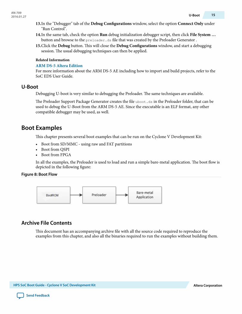
In all the examples, the Preloader is used to load and run a simple bare-metal application. The boot flow isdepicted in the following figure:
Figure 8: Boot Flow
Archive File ContentsThis document has an accompanying archive file with all the source code required to reproduce theexamples from this chapter, and also all the binaries required to run the examples without building them.
AN-7092016.01.27 U-Boot 15
HPS SoC Boot Guide - Cyclone V SoC Development Kit Altera Corporation
Send Feedback

The archive is called cv_boot_guide.zip and contains the following:
• prebuilt
• application
• hello-mkimage.bin
• fpga
• soc_system.sof
• preloaders
• sd_custom_partition
• preloader-mkpimage.bin
• sd_fat_partition
• preloader-mkpimage.bin
• qspi
• preloader-mkpimage.bin
• fpga
• preloader-mkpimage.bin
• sources
• cv_soc_devkit_boot_fpga_rd
• Altera-SoCFPGA-HardwareLib-Unhosted-CV-GNU.tar.gz
Related Informationcv_boot_guide.zip
Bare-Metal ApplicationThe bare-metal application used in all the examples simply displays the Hello World message over UART.
The application is included as an importable project called Altera-SoCFPGA-HardwareLib-Unhosted-CV-GNU.tar.gz. It can also be downloaded from the SoC Example Designs webpage.
Import the project archive in ARM DS-5 AE and build it. This will create the file hello-mkimage.bin,which is the image that will be loaded by the Preloader.
Related Information
• ARM DS-5 Altera EditionFor more information about the ARM DS-5 AE including how to import and build projects, refer tothe SoC EDS User Guide.
• SoC Example Designs webpageFor more information, refer to the SoC Example Designs webpage.
Booting from SD/MMC – Custom PartitionThis example demonstrates how to boot from the SD card, with the bare-metal image stored on the sameSD card custom partition as the Preloader.
16 Bare-Metal ApplicationAN-709
2016.01.27
Altera Corporation HPS SoC Boot Guide - Cyclone V SoC Development Kit
Send Feedback

Before you begin
To prevent the "Device Open Failed!" error message, ensure that you are operating in the following usermodes:
• Windows — "Administrator mode user"• Linux — "sudo mode"
The steps required to run this scenario are:
1. Build the sample bare-metal application or simply use the provided file hello-mkimage.bin directly.2. Generate a Preloader based on the GHRD provided with SoC EDS.
Make sure to select the following options:
• Check the option spl.boot.BOOT_FROM_SDMMC• Uncheck the other boot options (spl.boot.BOOT_FROM_RAM, spl.boot.BOOT_FROM_QSPI,
spl.boot.BOOT_FROM_NAND)
Note: spl.boot.SDMMC_NEXT_BOOT_IMAGE = 0x40000. This is the location where the bare-metalapplication image will need to be stored.
• Check the option spl.boot.SDRAM_SCRUBBING and spl.boot.SDRAM_SCRUB_REMAIN_REGION. Thiswill zero out the SDRAM, preventing any ECC errors to occur during bare-metal programexecution.
• Uncheck the option spl.boot.WATCHDOG_ENABLE. This is because we are not kicking the watchdogin our bare-metal application.
3. Compile the Preloader. This will create the file preloader-mkpimage.bin.4. Manually create an SD card with a custom partition with id=A2 using fdisk, or use the example SD
card image that comes with SoC EDS:
• Unzip the SD Card Image provided in the <SoCEDS installation folder>:\embedded\embeddedsw\socfpga\prebuilt_images\sd_card_linux_boot_image.tar.gz by usingthe command ‘tar -xzf <filename>’ from the Embedded Command Shell. This will createthe file sd_card_linux_boot_image.img.
• Use the free Win32DiskImager tool to write the file sd_card_linux_boot_image.img to an SDcard.
5. Write only the Preloader image to the SD card custom partition, using the SD card boot utility that ispart of SoC EDS:
• Start an Embedded Command Shell.• Run the command “alt-boot-disk-util -a write -p preloader-mkpimage.bin
-b hello-mkimage.bin -d <sd_card_drive_letter>”6. Set the board to boot from SD card by configuring the BOOTSEL jumpers like this:
• BOOTSEL0 (J28): left• BOOTSEL1 (J29): right• BOOTSEL2 (J30): left
7. Connect the board to the PC using the USB serial connection, and start a serial terminal on the PC,using 115,200-8-N-1.
8. Insert the SD card on the board socket and power-cycle the board or reset the HPS by pressing theCOLD reset button (S7).
AN-7092016.01.27 Booting from SD/MMC – Custom Partition 17
HPS SoC Boot Guide - Cyclone V SoC Development Kit Altera Corporation
Send Feedback

The board will boot, Preloader messages will be displayed, then “Hello World” will be displayed by thebare-metal application.
Figure 9: Custom Partition
Related Information
• Altera SoC Embedded Design Suite User GuideFor more information about SoC EDS, ARM DS-5, Preloader Generator and SD Card Boot Utility,refer to the SoC EDS User Guide.
• Win32 Disk Imager
Booting from SD/MMC – FAT PartitionThis example demonstrates how to boot from the SD card, with the bare-metal image stored on the FATpartition on the SD card.
Note: The Preloader is still stored on the custom partition.
Before you begin
To prevent the "Device Open Failed!" error message, ensure that you are operating in the following usermodes:
• Windows — "Administrator mode user"• Linux — "sudo mode"
18 Booting from SD/MMC – FAT PartitionAN-709
2016.01.27
Altera Corporation HPS SoC Boot Guide - Cyclone V SoC Development Kit
Send Feedback

The steps required to run this scenario are:
1. Build the sample bare-metal application or simply use the provided file hello-mkimage.bin directly.2. Generate a Preloader based on the GHRD provided with SoC EDS. Make sure to select the following
options:
• Check the option spl.boot.BOOT_FROM_SDMMC• Uncheck the other boot options (spl.boot.BOOT_FROM_RAM, spl.boot.BOOT_FROM_QSPI,
spl.boot.BOOT_FROM_NAND)• Check the option spl.boot.FAT_SUPPORT. This will tell the Preloader to load the bare-metal
application from the FAT partition.• Edit the field spl.boot.FAT_LOAD_PAYLOAD_NAME to contain the name of the bare-metal image:
hello-mkimage.bin
• Check the option spl.boot.SDRAM_SCRUBBING and spl.boot.SDRAM_SCRUB_REMAIN_REGION. Thiswill zero out the SDRAM, preventing any ECC errors to occur during bare-metal programexecution.
• Uncheck the option spl.boot.WATCHDOG_ENABLE. This is because we are not kicking the watchdogin our bare-metal application.
3. Compile the Preloader. This will create the file preloader-mkpimage.bin.4. Manually create an SD card with a custom partition with id=A2 using fdisk, or use the example SD
card image that comes with SoC EDS:
• Unzip the SD Card Image provided in the <SoCEDS installation folder>:\embedded\embeddedsw\socfpga\prebuilt_images\sd_card_linux_boot_image.tar.gz by usingthe command ‘tar -xzf <filename>’ from the Embedded Command Shell. This will createthe file sd_card_linux_boot_image.img.
• Use the free Win32DiskImager tool to write the file sd_card_linux_boot_image.img to an SDcard.
5. Write both the Preloader image and the Bare-metal application images to the SD card custom partition,using the SD card boot utility that is part of SoC EDS:
• Start an Embedded Command Shell.• Run the command “alt-boot-disk-util -a write -p preloader-mkpimage.bin
-d <sd_card_drive_letter”6. Write the bare-metal application image to the SD card FAT partition, using for example drag and drop
in Windows Explorer.7. Set the board to boot from SD card by configuring the BOOTSEL jumpers like this:
• BOOTSEL0 (J28): left• BOOTSEL1 (J29): right• BOOTSEL2 (J30): left
8. Connect the board to the PC using the USB serial connection, and start a serial terminal on the PC,using 115,200-8-N-1.
9. Insert the SD card on the board socket and power-cycle the board or reset the HPS by pressing theCOLD reset button (S7).
The board will boot, Preloader messages will be displayed, then “Hello World” will be displayed by thebare-metal application.
AN-7092016.01.27 Booting from SD/MMC – FAT Partition 19
HPS SoC Boot Guide - Cyclone V SoC Development Kit Altera Corporation
Send Feedback

Figure 10: FAT Partition
Related Information
• Altera SoC Embedded Design Suite User GuideFor more information about SoC EDS, ARM DS-5, Preloader Generator and SD Card Boot Utility,refer to the SoC EDS User Guide.
• Win32 Disk Imager
Booting from QSPI FlashThis example demonstrates how to boot from the QSPI Flash. Both the Preloader and the Bare-metalapplication are stored in QSPI Flash.
The steps required to run this scenario are:
1. Build the sample bare-metal application or simply use the provided file hello-mkimage.bin directly.2. Generate a Preloader based on the GHRD provided with SoC EDS. Make sure to select the following
options:
20 Booting from QSPI FlashAN-709
2016.01.27
Altera Corporation HPS SoC Boot Guide - Cyclone V SoC Development Kit
Send Feedback

• Check the option spl.boot.BOOT_FROM_QSPI• Uncheck the other boot options (spl.boot.BOOT_FROM_RAM, spl.boot.BOOT_FROM_SDMMC,
spl.boot.BOOT_FROM_NAND)
Note: spl.boot.QSPI_NEXT_BOOT_IMAGE = 0x60000. This is the location where the bare-metalapplication image will need to be stored.
• Check the option spl.boot.SDRAM_SCRUBBING and spl.boot.SDRAM_SCRUB_REMAIN_REGION. Thiswill zero out the SDRAM, preventing any ECC errors to occur during bare-metal programexecution.
• Uncheck the option spl.boot.WATCHDOG_ENABLE. This is because we are not kicking the watchdogin our bare-metal application.
3. Compile the Preloader. This will create the file preloader-mkpimage.bin.4. Set the board to boot from SD card by configuring the BOOTSEL jumpers like this:
• BOOTSEL0 (J28): left• BOOTSEL1 (J29): left• BOOTSEL2 (J30): left
5. Connect the USB Blaster USB cable from board to the host PC. This is needed by the HPS FlashProgrammer used in the next step.
6. Write the Preloader and the application images to the QSPI Flash by starting an Embedded CommandShell and then running the following commands:
• quartus_hps -c 1 -o PV preloader-mkpimage.bin• quartus_hps -c 1 -o PV -a 0x60000 hello-mkimage.bin
7. Power-cycle the board or reset the HPS by pressing the COLD reset button (S7).
The board will boot, Preloader messages will be displayed, then “Hello World” will be displayed by thebare-metal application.
AN-7092016.01.27 Booting from QSPI Flash 21
HPS SoC Boot Guide - Cyclone V SoC Development Kit Altera Corporation
Send Feedback

Figure 11: Booting from QSPI Flash
Related InformationAltera SoC Embedded Design Suite User GuideFor more information about SoC EDS, ARM DS-5, Preloader Generator and SD Card Boot Utility, refer tothe SoC EDS User Guide.
Booting from FPGAThis section presents a complete example on how to boot from FPGA.
When instructed to boot from FPGA, the Boot ROM performs the following operations:
1. Waits for the FPGA fabric to be configured2. Waits for FPGA to be in user mode3. Opens the HPS-to-FPGA bridge4. Jumps to address 0xC0000000 (offset 0 from the HPS-to-FPGA bridge)
Overview
In this example, we have the Preloader running from FPGA, but then it will load the bare-metal imagethat we have on SD/MMC custom partition. If desired, the Preloader can also be configured to jump to anabsolute address, that may also be located in the FPGA fabric address space.
22 Booting from FPGAAN-709
2016.01.27
Altera Corporation HPS SoC Boot Guide - Cyclone V SoC Development Kit
Send Feedback

The boot flow of this example is described below:
Figure 12: Boot Flow
In order to achieve booting from FPGA the following are required:
• BSEL needs to be set to 0x1 - Boot from FPGA• FPGA image needs to have an on-chip memory instantiated, mapped at offset 0x0 behind the
HPS2FPGA bridge. The memory needs to be loaded with Preloader executable binary• FPGA image needs to drive the value of the following two signals to HPS, since they are required by
Boot ROM:
• f2h_boot_from_fpga_ready - indicates that the Boot ROM can boot from FPGA if BSEL = 0x1• f2h_boot_from_fpga_on_failure - indicates that the Boot ROM can boot from FPGA as a
fallback, if it failed booting from the selected BSEL• Preloader executable (.text) section needs to be linked to address 0xC0000000 (equivalent of offset 0x0
behind the HPS2FPGA bridge)• Preloader executable (.data) sections need to be linked to address 0xFFFF0000 (the HPS OCRAM)
The complete flow is described in the following figure:
Figure 13: Complete Flow
Note: The design needs to be compiled once in order to obtain the handoff folder, which is used togenerate the Preloader. Once the Preloader hex file is obtained, the design is compiled again inorder to have the FPGA memory initialized with the contents of the hex file.
AN-7092016.01.27 Overview 23
HPS SoC Boot Guide - Cyclone V SoC Development Kit Altera Corporation
Send Feedback

Hardware DesignThis section presents a very simple hardware design that was used for this example. You will need ACDS tobe installed on your host PC to be able to reproduce this example.
Note: The design is already provided with this guide. It does not need to be re-created by the user. But itwill need to be re-compiled if the Preloader hex file is changed.
The design is based on the Altera GHRD, with a reduced number of components:
• HPS - Hard Processor Instance• SysID - System ID• HPS Boot Memory - FPGA memory used to store Preloader binary• Clk - Clock and Reset source
24 Hardware DesignAN-709
2016.01.27
Altera Corporation HPS SoC Boot Guide - Cyclone V SoC Development Kit
Send Feedback

The following picture presents the System Contents view for the hardware design:
Figure 14: System Contents View for the Hardware Design
AN-7092016.01.27 Hardware Design 25
HPS SoC Boot Guide - Cyclone V SoC Development Kit Altera Corporation
Send Feedback

The HPS Component needs to be configured to enable the Boot from FPGA signals as shown in thescreenshot below:
Figure 15: Enable Boot From FPGA Signals
The HPS Boot Memory needs to be set to 8-bit width, and be initialized with a hex file containing thePreloader image. The following screenshot show the memory settings that were used for this example.
Note: The Preloader image is stored in the file named software/spl_bsp/preloader.hex.
26 Hardware DesignAN-709
2016.01.27
Altera Corporation HPS SoC Boot Guide - Cyclone V SoC Development Kit
Send Feedback

Figure 16: On-Chip Memory Parameters
AN-7092016.01.27 Hardware Design 27
HPS SoC Boot Guide - Cyclone V SoC Development Kit Altera Corporation
Send Feedback

Note: • The HPS bus f2h_boot_from_fpga was exported by double-clicking the corresponding cell inthe Export column.
• The HPS Boot Memory was connected to the h2f AXI bus.• The HPS Boot Memory was set to a base address of 0x0000000.• The f2h_boot_from_fpga signals need to be tied at the top level to the proper values. For this
example, they were tied like this in the file rd_top.v:
// SoC sub-system modulesoc_system soc_inst ( ... .hps_0_f2h_boot_from_fpga_boot_from_fpga_ready (1'b1), .hps_0_f2h_boot_from_fpga_boot_from_fpga_on_failure (1'b0));
Building and Running the ExampleThis section presents the steps required in order to build and run the boot from FPGA example.
Note: All the binaries are also provided with the archive file that accompanies this document.
Before you begin
To prevent the "Device Open Failed!" error message, ensure that you are operating in the following usermodes:
• Windows — "Administrator mode user"• Linux — "sudo mode"
1. Build the sample bare-metal application or simply use the provided file hello-mkimage.bin directly.2. Compile the provided Booting from FPGHA Hardware Design in Intel® Quartus® Prime, to create the
handoff information.3. Generate the Preloader based on the compiled hardware project. Select the following options:
• Check the option spl.boot.BOOT_FROM_SDMMC• Uncheck the other boot options (spl.boot.BOOT_FROM_RAM, spl.boot.BOOT_FROM_QSPI,
spl.boot.BOOT_FROM_NAND)• Uncheck the option spl.boot.FAT_SUPPORT. This will tell the Preloader to load the bare-metal
application from the custom partition.
Note: spl.boot.SDMMC_NEXT_BOOT_IMAGE = 0x40000. This is the location where the bare-metalapplication image will need to be stored.
• Check the option spl.boot.SDRAM_SCRUBBING and spl.boot.SDRAM_SCRUB_REMAIN_REGION. Thiswill zero out the SDRAM, preventing any ECC errors to occur during bare-metal programexecution.
• Uncheck the option spl.boot.WATCHDOG_ENABLE. This is because we are not kicking the watchdogin our bare-metal application.
• Check the option spl.boot.EXE_ON_FPGA.4. Compile the Preloader. This will create the Preloader executable.5. Convert the Preloader executable to hex file by using the following command in the Preloader folder:
arm-altera-eabi-objcopy -O ihex --adjust-vma -0xc0000000 uboot-socfpga/spl/u-boot-
spl preloader.hex
6. Compile the hardware design again, to take into account the newly created hex file.
28 Building and Running the ExampleAN-709
2016.01.27
Altera Corporation HPS SoC Boot Guide - Cyclone V SoC Development Kit
Send Feedback

Note: The hex file is expected to be located in the <hardware_design_folder>/software/spl_bsp/preloader.hex. This will create the file <hardware_design_folder>/output_files/soc_system.sof.
7. Manually create an SD card with a custom partition with id=A2 using fdisk, or use the example SDcard image that comes with SoC EDS:
• Unzip the SD Card Image provided in the <SoCEDS installation folder>:\embedded\embeddedsw\socfpga\prebuilt_images\sd_card_linux_boot_image.tar.gz by usingthe command ‘tar -xzf <filename>’ from the Embedded Command Shell. This will createthe file sd_card_linux_boot_image.img.
• Use the free Win32DiskImager tool to write the file sd_card_linux_boot_image.img to an SDcard.
8. Write the Bare-metal application image to the SD card custom partition, using the SD card boot utilitythat is part of SoC EDS:
• Start an Embedded Command Shell• Run the command “alt-boot-disk-util -a write -b hello-mkimage.bin -d
<sd_card_drive_letter>”9. Configure the Cyclone V board to boot from FPGA by setting the BOOTSEL jumpers like this:
• BOOTSEL0 (J28): left• BOOTSEL1 (J29): right• BOOTSEL2 (J30): right
10.Connect the board to the PC using the USB serial connection, and start a serial terminal on the PC,using 115,200-8-N-1.
11.Insert the SD card on the board.12.Power up the board.
There should be nothing coming from the board on the serial terminal, since the FPGA is notconfigured, so the Boot ROM will not jump to FPGA yet.
13.Configure the FPGA by using the Intel Quartus Prime Programmer, with the (.sof) file.
Note: The (.sof) file is already included in the archive that accompanies this document.14.Press the HPS Cold Reset button (S7).15.The serial console will show the Preloader being run from FPGA, then the bare-metal application being
run from the SD card.
AN-7092016.01.27 Building and Running the Example 29
HPS SoC Boot Guide - Cyclone V SoC Development Kit Altera Corporation
Send Feedback

Figure 17: Serial Console of Preloader Running from FPGA
Related InformationWin32 Disk Imager
Document Revision History
Table 9: Document Revision History
Date Version Changes
January 2016 2016.01.27 Added note to remind user to be in administrator or sudomode when using alt-boot-disk-util.
April 2015 2015.04.27 • Updated the SD card boot utility command• Fixed incorrect spelling of "BootROM" in figures
March 2015 2015.03.26 Fixed broken links.
December 2014 2014.12.15 Added information for Boot Time Optimization and BootDebug.
30 Document Revision HistoryAN-709
2016.01.27
Altera Corporation HPS SoC Boot Guide - Cyclone V SoC Development Kit
Send Feedback