HPR Open Loop Pumps Data and Specifications · 1 HPR Open Loop Pumps Data and Specifications HPR 55...
14
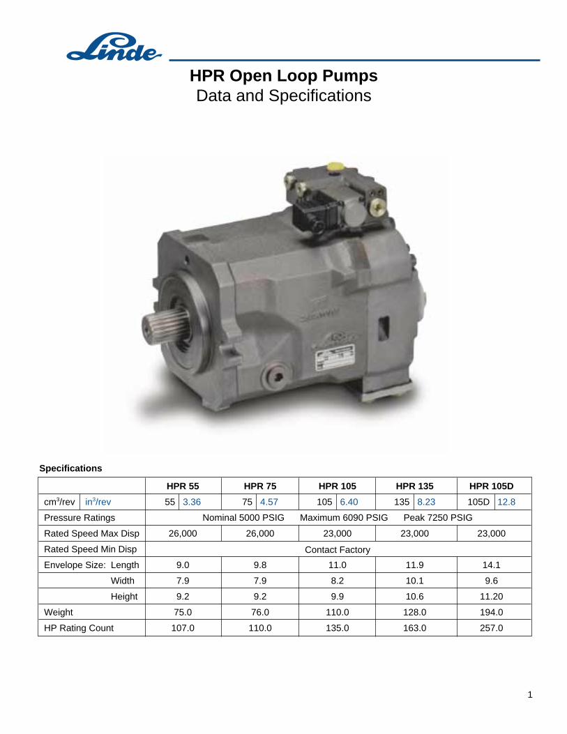
1 HPR Open Loop Pumps Data and Specifications HPR 55 55 3.36 26,000 9.0 7.9 9.2 75.0 107.0 cm 3 /rev in 3 /rev Pressure Ratings Rated Speed Max Disp Rated Speed Min Disp Envelope Size: Length Width Height Weight HP Rating Count HPR 75 75 4.57 26,000 9.8 7.9 9.2 76.0 110.0 HPR 105 105 6.40 23,000 11.0 8.2 9.9 110.0 135.0 HPR 135 135 8.23 23,000 11.9 10.1 10.6 128.0 163.0 HPR 105D 105D 12.8 23,000 14.1 9.6 11.20 194.0 257.0 Nominal 5000 PSIG Maximum 6090 PSIG Peak 7250 PSIG Contact Factory Specifications
Transcript of HPR Open Loop Pumps Data and Specifications · 1 HPR Open Loop Pumps Data and Specifications HPR 55...
1
HPR Open Loop PumpsData and Specifications
HPR 55
55 3.36
26,000
9.0
7.9
9.2
75.0
107.0
cm3/rev in3/rev
Pressure Ratings
Rated Speed Max Disp
Rated Speed Min Disp
Envelope Size: Length
Width
Height
Weight
HP Rating Count
HPR 75
75 4.57
26,000
9.8
7.9
9.2
76.0
110.0
HPR 105
105 6.40
23,000
11.0
8.2
9.9
110.0
135.0
HPR 135
135 8.23
23,000
11.9
10.1
10.6
128.0
163.0
HPR 105D
105D 12.8
23,000
14.1
9.6
11.20
194.0
257.0
Nominal 5000 PSIG Maximum 6090 PSIG Peak 7250 PSIG
Contact Factory
Specifications

HPR 75 Open Loop PumpWith Load Sensing and Summated Power Control Circuit
Circuit Diagram
Not component parts of HPR 02 :
External connection line
Variable throttle ( control valve )
5
1
External connection lineLoad-sensing line
2
EXPLANATIONSP Discharge portT Suction portPZ Pressure port, gear pumpLS Load sensing connectionMP Gauge port, pump pressureX Gauge port, actuating pressureL/U Drain (filling, vent) ports Port enabling case to be filled with oilGP Gear pump, pressure portGS Gear pump, suction port

HPR 75 Open Loop PumpWith Load Sensing and Summated Power Control
3
Summated power control
The power summation feature is part of the control. It limits the flow of the swash plate pump in such a way that, depending on the working pressure,the power intake of the swash plate pump remains constant.A second area on the high pressure sensing piston accounts for the power of an additional working circuit.
Functional Description
The HPR 75 - 02 R TL E models are self-priming swash plate type axial piston pumps with a variable displacement volume for open loops.
The controller of the HPR pump is a combination of two types of controls:- load-sensing control- summated power control.
Load-sensing control
The load-sensing control of the HPR pump controls the displacement starting from a zero pump flow condition. If no flow is demanded, only the “stand-by” pressure required by the system is maintained by the pump. When the main control valves are actuated, the load-sensing controller of the HPR automatically matches the displacement and the flow to the “flow demand” required by the control valves, up to the maximum available pump flow. The pump pressure is only approx-imately 20 bar higher than the (highest) pressure of the active loads. Thus, the load-sensing control system is a “flow on demand” control, which matches the pump output flow to the variable metering orifice size by keeping a constant ∆p across the measuring orifice of the directional control valve.

4
HPR 75 Open Loop PumpWith Load Sensing and Summated Power Control
Pump pressures P and PZ act on two sensing areas of the summated power control (6). Aslong as the resulting force is smaller than the preloaded spring force (7), the signal generatedby the LS control is directly related to the large area of the control piston. If this force becomesstronger than the spring preload, the summated power regulator overrides the shiftingsignal generated by the LS control and connects pump pressure to the large piston area.This leads to reducing the pump swash angle.A stroke feedback (8) informs the summated power control of the swash angle change at the detector spring, until equilibrium is achieved between the spring force and hydraulic force P+PZ.When pressure is relieved, this procedure performs the opposite way.
Technical description: summated power control
When there is no function activated and when the control spool (1) is in the neutral position (see circuit diagram), then the pump (2) delivers only such a quantity of oil that the pressurein the pump line (3), which acts on the load-sensing controller (4) (LS), maintains the spring on the opposite side of the control spool and the swivel spring (on the displacement piston Vmin) in balance. Every change in pressure P and LS makes the LS spool move and leadsto an immediate change of pump displacement. Upon actuation of the control spool (1), the connection from the pump output (2) to the load port is opened. Essentially, the area which is opened represents a metering orifice.If oil is to flow continuously through this orifice, independent of the load pressure, then the pressure difference at this point must be kept constant. If the controlspool (1) is opened, the pump pressure proceeds up to this function. At the same time, theload pressure acts upon the spring side of the LS spool (4), through the LS line (5), causingthe pump (2) to go on stroke and the pressure in the P line (3) to increase.If the pump pressure exceeds the load pressure, the load starts moving and the following oil flow produces a drop in pressure across the control edge (metering orifice). Balance isachieved when this drop in pressure corresponds to the spring preload of the LS con-troller (4).The pump (2) reacts to each control spool movement, fully stabilizing each variationof the metering orifice and maintaining a constant pressure difference.
Technical description: load-sensing control
Technical Description

5
HPR 75 Open Loop PumpWith Load Sensing and Summated Power Control
1
4
5
7
2 3 6
Basic Design of Rotating Group
1 Shaft2 Piston assembly3 Cylinder barrel4 Control5 Swash plate6 Port plate7 Gear pump
EXPLANATIONS

6
HPR - 02 Open Loop PumpWith Load Sensing and Electric Pressure Control
Solenoid switching operations
M d.c. proportional solenoid
12/24 V, according to specification
P
UT
LS
L
X1
LS
X
0 max
A
M
4
3
2
76
8
Not component parts of HPR 02 :
External connection line
Variable throttle ( control valve )
5
1
External connection lineLoad-sensing line 5
Variable orifice(Control valve)
p
1
EXPLANATIONS
P
T
L U
LS
X
Discharge port SAE
Suction port SAE
Drain (filling, vent) portsPort enabling case to be filled with oil
X1
Gauge port, actuating pressure M14 x 1.5
Control pressure port for emergency operation (max. 30 bar) M14x1.5
Load-sensing connection 2x M14 x 1.5
Gauge port, control pressure M14 x 1.5A
Circuit Diagram

HPR - 02 Open Loop PumpWith Load Sensing and Electric Pressure Control
RV
1
10
2
3
4 5
6
3
7
8
9
12 11
1314
load sensing control line
P - line to the actuators
7
1 Check valve2 Proportional solenoid3 Set screw control pressure4 Gauge port A5 Control pressure port for emergency operation X16 Pilot spool (el. pressure control valve)7 Set screw ∆p = Pp - LSp 8 Pilot spool load sensing control9 Gauge port X10 Gauge port LS11 Actuator piston Vmax12 Actuator piston Vmin13 Swash plate14 Swivel spring
EXPLANATIONS
Basic Design of Control System

8
HPR - 02 Open Loop PumpWith Load Sensing and Electric Pressure Control
Electrical pressure control valve
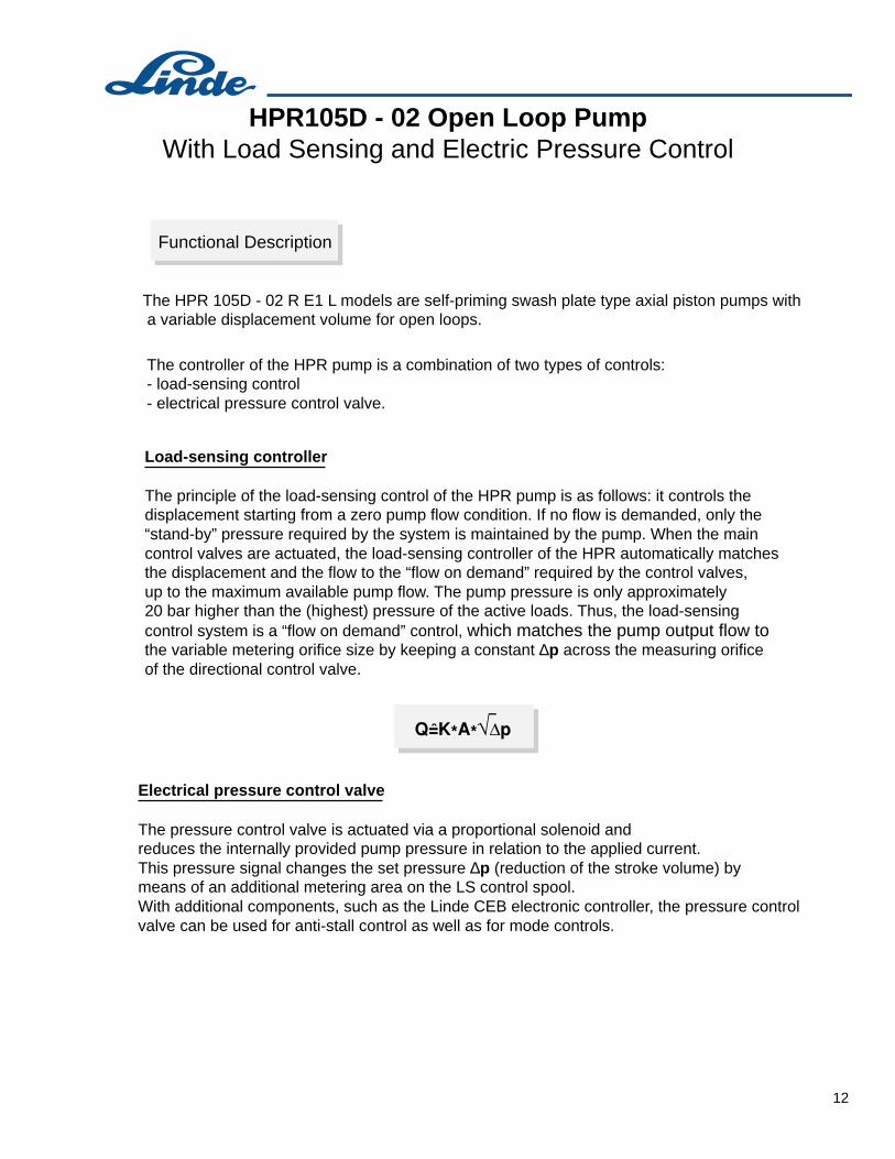
The pressure control valve is actuated via a proportional solenoid andreduces the internally provided pump pressure in relation to the applied current.This pressure signal changes the set pressure ∆p (reduction of the stroke volume) by means of an additional metering area on the LS control spool.With additional components, such as the Linde CEB electronic controller, the pressure controlvalve can be used for anti-stall control as well as for mode controls.
The HPR - 02 R E1 L models are self-priming swash plate type axial piston pumps with a variable displacement volume for open loops.
The controller of the HPR pump is a combination of two types of controls:- load-sensing control- electrical pressure control valve.
Load-sensing controller
The principle of the load-sensing control of the HPR pump is as follows: it controls the displacement starting from a zero pump flow condition. If no flow is demanded, only the “stand-by” pressure required by the system is maintained by the pump. When the main control valves are actuated, the load-sensing controller of the HPR automatically matches the displacement and the flow to the “flow on demand” required by the control valves, up to the maximum available pump flow. The pump pressure is only approximately20 bar higher than the (highest) pressure of the active loads. Thus, the load-sensing control system is a “flow on demand” control, which matches the pump output flow tothe variable metering orifice size by keeping a constant ∆p across the measuring orifice of the directional control valve.
Functional Description

9
HPR - 02 Open Loop PumpWith Load Sensing and Electric Pressure Control
When there is no function activated and when the control spool (1) is in the neutral position (see circuit diagram), then the pump (2) delivers only such a quantity of oil that the pressurein the pump line (3), which acts on the load-sensing controller (4) (LS), maintains the spring on the opposite side of the control spool and the swivel spring (on the displacement piston Vmin) in balance. Every change in pressure P and LS makes the LS spool move and leadsto an immediate change of pump displacement. Upon actuation of the control spool (1), the connection from the pump output (2) to the load port is opened. Essentially, the area which is opened represents a metering orifice.If oil is to flow continuously through this orifice, independent of the load pressure, then the pressure difference at this point must be kept constant. If the controlspool (1) is opened, the pump pressure proceeds up to this function. At the same time, theload pressure acts upon the spring side of the LS spool (4), through the LS line (5), causingthe pump (2) to go on stroke and the pressure in the P line (3) to increase.If the pump pressure exceeds the load pressure, the load starts moving and the following oil flow produces a drop in pressure across the control edge (metering orifice). Balance isachieved when this drop in pressure corresponds to the spring preload of the LS con-troller (4).The pump (2) reacts to each control spool movement, fully stabilizing each variation of the metering orifice and maintaining a constant pressure difference.
Technical description: load-sensing controller
When the solenoid (6) is in the de-energized state, the pilot spool of the pressure control valve (7) is in the position in which the connection channel (3) (pump pressure) to thechannel (8) (metering area on LS pilot) is blocked. The channel (8) is released to the tank(interior of HPR pump housing). If a predetermined current exists in the solenoid (6), then the solenoid pin moves the pilot spool of the pressure control valve (7) to the position in which the channels (3) and (8) are connected. Solenoid force “Fm” is then converted into hydraulic force “Fh” proportionally in relation to the level of the applied current. This signal (control pressure) causes the set pressure difference ∆p to be reduced by means of an additional metering area on the LS control spool (4).Result: A reduction of the displacement of the HPR pump.
Technical description: electrical pressure control valve
Technical Description
10
HPR - 02 Open Loop PumpWith Load Sensing and Electric Pressure Control
1
2 3
54
67
8
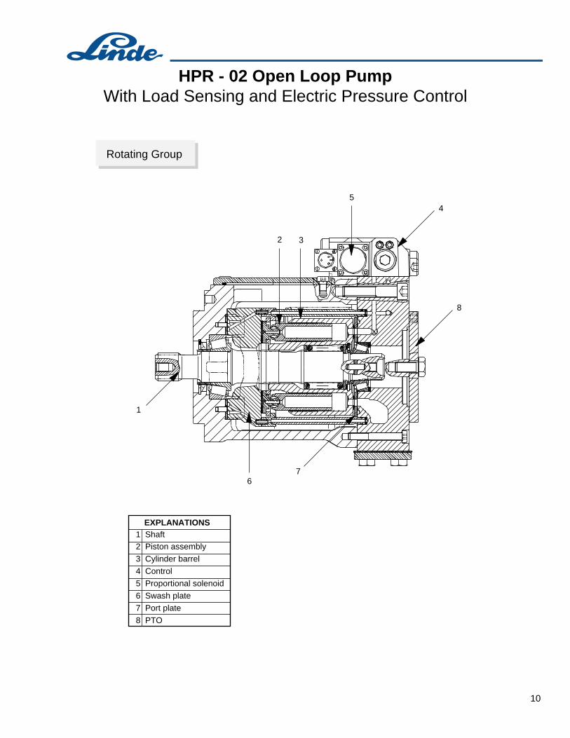
1 Shaft2 Piston assembly
3 Cylinder barrel
4 Control
5 Proportional solenoid
6 Swash plate
7 Port plate
8 PTO
EXPLANATIONS
Rotating Group

11
HPR105D - 02 Open Loop PumpWith Load Sensing and Electric Pressure Control
Solenoid switching operationsM d.c. proportional solenoid12/24 V, according to specification
external connection line
load-sensing line 5
Circuit Diagram
Not component parts of HPR 105D - 02:
external connection lines
Variable throttle ( control valve )
5 9
1
p
4
3
2
76
8
measuring orificein the valve
1
A
0 max
M
1000max
100
GP
GS
to the actuators
2
3
9 9
X
T
P1 P2
L2L1
U1 U2
LS1
LS2
X1
19
EXPLANATIONS
Control pressure port for emergency operation(max. 30 bar) M14x1.5
T Suction port, SAEX1
Gauge port, control pressure M14 x 1.5A
Discharge port pump, SAE P1, P2
Load-sensing connection 2x M14 x 1.5LS1, LS2
Drain (filling, vent) ports Port enabling case to be filed with oil.
Gauge port, actuating pressure M14 x 1.5
Discharge port auxiliary pump
X
L1, L2
U1, U2
GP
GS Suction port auxiliary pump
Drain (filling, vent) ports Port enabling case to be filed with oil.
12
HPR105D - 02 Open Loop PumpWith Load Sensing and Electric Pressure Control
Electrical pressure control valve
The pressure control valve is actuated via a proportional solenoid andreduces the internally provided pump pressure in relation to the applied current.This pressure signal changes the set pressure ∆p (reduction of the stroke volume) by means of an additional metering area on the LS control spool.With additional components, such as the Linde CEB electronic controller, the pressure controlvalve can be used for anti-stall control as well as for mode controls.
The HPR 105D - 02 R E1 L models are self-priming swash plate type axial piston pumps with a variable displacement volume for open loops.
The controller of the HPR pump is a combination of two types of controls:- load-sensing control- electrical pressure control valve.
Load-sensing controller
The principle of the load-sensing control of the HPR pump is as follows: it controls the displacement starting from a zero pump flow condition. If no flow is demanded, only the “stand-by” pressure required by the system is maintained by the pump. When the main control valves are actuated, the load-sensing controller of the HPR automatically matches the displacement and the flow to the “flow on demand” required by the control valves, up to the maximum available pump flow. The pump pressure is only approximately 20 bar higher than the (highest) pressure of the active loads. Thus, the load-sensing control system is a “flow on demand” control, which matches the pump output flow to the variable metering orifice size by keeping a constant ∆p across the measuring orifice of the directional control valve.
Functional Description
13
HPR105D - 02 Open Loop PumpWith Load Sensing and Electric Pressure Control
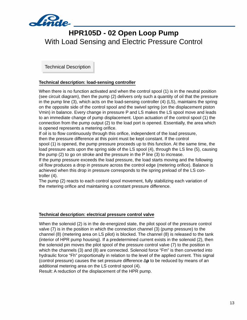
When there is no function activated and when the control spool (1) is in the neutral position (see circuit diagram), then the pump (2) delivers only such a quantity of oil that the pressurein the pump line (3), which acts on the load-sensing controller (4) (LS), maintains the spring on the opposite side of the control spool and the swivel spring (on the displacement piston Vmin) in balance. Every change in pressure P and LS makes the LS spool move and leadsto an immediate change of pump displacement. Upon actuation of the control spool (1) the connection from the pump output (2) to the load port is opened. Essentially, the area which is opened represents a metering orifice.If oil is to flow continuously through this orifice, independent of the load pressure, then the pressure difference at this point must be kept constant. If the controlspool (1) is opened, the pump pressure proceeds up to this function. At the same time, theload pressure acts upon the spring side of the LS spool (4), through the LS line (5), causingthe pump (2) to go on stroke and the pressure in the P line (3) to increase.If the pump pressure exceeds the load pressure, the load starts moving and the following oil flow produces a drop in pressure across the control edge (metering orifice). Balance isachieved when this drop in pressure corresponds to the spring preload of the LS con-troller (4).The pump (2) reacts to each control spool movement, fully stabilizing each variation of the metering orifice and maintaining a constant pressure difference.
Technical description: load-sensing controller
When the solenoid (2) is in the de-energized state, the pilot spool of the pressure control valve (7) is in the position in which the connection channel (3) (pump pressure) to thechannel (8) (metering area on LS pilot) is blocked. The channel (8) is released to the tank(interior of HPR pump housing). If a predetermined current exists in the solenoid (2), then the solenoid pin moves the pilot spool of the pressure control valve (7) to the position in which the channels (3) and (8) are connected. Solenoid force “Fm” is then converted into hydraulic force “Fh” proportionally in relation to the level of the applied current. This signal (control pressure) causes the set pressure difference ∆p to be reduced by means of anadditional metering area on the LS control spool (4).Result: A reduction of the displacement of the HPR pump.
Technical description: electrical pressure control valve
Technical Description

14
HPR105D - 02 Open Loop PumpWith Load Sensing and Electric Pressure Control
Basic Rotating Group
1
2
2
3
3
4
4
5
6
6
7 8
1 Shaft2 Piston assembly
3 Cylinder barrel
4 Port plate5 Gear pump
6 Swash plate
7 Clutch
8 Port plate housing
EXPLANATIONS