HPE StoreEver MSL3040 Tape Library User and …...HPE StoreEver MSL3040 Tape Library User and...
240
HPE StoreEver MSL3040 Tape Library User and Service Guide Part Number: Q6Q62-00056a Published: November 2019 Edition: 7 Abstract This guide provides information on installing, configuring, upgrading, and troubleshooting the library. This guide is intended for system administrators and other users who need physical and functional knowledge of the library.
Transcript of HPE StoreEver MSL3040 Tape Library User and …...HPE StoreEver MSL3040 Tape Library User and...

HPE StoreEver MSL3040 Tape Library User andService Guide
Part Number: Q6Q62-00056aPublished: November 2019Edition: 7
Abstract
This guide provides information on installing, configuring, upgrading, and troubleshooting the library. Thisguide is intended for system administrators and other users who need physical and functional knowledge ofthe library.

© Copyright 2017, 2019 Hewlett Packard Enterprise Development LP
Notices
The information contained herein is subject to change without notice. The only warranties for Hewlett Packard Enterpriseproducts and services are set forth in the express warranty statements accompanying such products and services.Nothing herein should be construed as constituting an additional warranty. Hewlett Packard Enterprise shall not be liablefor technical or editorial errors or omissions contained herein.
Confidential computer software. Valid license from Hewlett Packard Enterprise required for possession, use, or copying.Consistent with FAR 12.211 and 12.212, Commercial Computer Software, Computer Software Documentation, andTechnical Data for Commercial Items are licensed to the U.S. Government under vendor's standard commercial license.
Links to third-party websites take you outside the Hewlett Packard Enterprise website. Hewlett Packard Enterprise has nocontrol over and is not responsible for information outside the Hewlett Packard Enterprise website.
Acknowledgments
Intel®, Itanium®, Optane®, Pentium®, Xeon®, Intel Inside®, and the Intel Inside logo are trademarks of Intel Corporation inthe U.S. and other countries.
Microsoft® and Windows® are either registered trademarks or trademarks of Microsoft Corporation in the United Statesand/or other countries.
Adobe® and Acrobat® are trademarks of Adobe Systems Incorporated.
Java® and Oracle® are registered trademarks of Oracle and/or its affiliates.
UNIX® is a registered trademark of The Open Group.

Contents
Overview.............................................................................................................................9Front panel...........................................................................................................................................................................................................................9Rear panel.........................................................................................................................................................................................................................10USB ports...........................................................................................................................................................................................................................11Tape drive back panels............................................................................................................................................................................................. 11
LTO-6 Fibre Channel tape drive back panel...............................................................................................................................11LTO-6 SAS tape drive back panel.....................................................................................................................................................12LTO-7 and LTO-8 Fibre Channel tape drive back panel.....................................................................................................12LTO-7 and LTO-8 SAS tape drive back panel...........................................................................................................................12
MSL3040 power supply LEDs...............................................................................................................................................................................13Module and tape drive numbering.....................................................................................................................................................................13MSL3040 storage slots.............................................................................................................................................................................................13Encryption.........................................................................................................................................................................................................................14
HPE StoreEver 1/8 G2 Tape Autoloader and MSL Tape Libraries Encryption Kit .............................................15KMIP key manager integration............................................................................................................................................................15
Data cartridges...............................................................................................................................................................................................................15LTO-7 Type M media for LTO-8 drives.........................................................................................................................................16Guidelines for using and maintaining data cartridges...........................................................................................................16Write-protecting data cartridges.......................................................................................................................................................17Read and write compatibility................................................................................................................................................................17Supported media.........................................................................................................................................................................................18
HPE Command View for Tape Libraries..........................................................................................................................................................19HPE StoreEver TapeAssure Advanced..........................................................................................................................................20HPE Data Verification...............................................................................................................................................................................20Connecting cables for Data Verification........................................................................................................................................21
Path failover features.................................................................................................................................................................................................21Secure Manager.............................................................................................................................................................................................................23
Installing the library.......................................................................................................24Planning the installation...........................................................................................................................................................................................24
Location requirements.............................................................................................................................................................................25Module and rack layout guidelines...................................................................................................................................................25FC connection information.....................................................................................................................................................................25SAS connection information.................................................................................................................................................................26Library partition guidelines...................................................................................................................................................................28
Preparing the host....................................................................................................................................................................................................... 28Unpacking the shipping containers................................................................................................................................................................... 29Installing the shelves in the rack..........................................................................................................................................................................30Installing the base module in the rack..............................................................................................................................................................33Preparing the top and bottom modules..........................................................................................................................................................33
Moving the top cover plate...................................................................................................................................................................34Moving the bottom cover plate.......................................................................................................................................................... 35
Installing the expansion modules in a rack....................................................................................................................................................36Aligning and connecting modules.......................................................................................................................................................................36Installing optional power supplies......................................................................................................................................................................38Installing tape drives...................................................................................................................................................................................................38Connecting the Fibre Channel cables............................................................................................................................................................... 39
3

Connecting the SAS cable........................................................................................................................................................................................39Powering on the library.............................................................................................................................................................................................40Initiating the configuration wizard.....................................................................................................................................................................40Verifying the host connections.............................................................................................................................................................................41Configuring the FC interface..................................................................................................................................................................................41Labeling tape cartridges...........................................................................................................................................................................................42Loading tape cartridges............................................................................................................................................................................................42Verifying the installation..........................................................................................................................................................................................43
Downloading product firmware..........................................................................................................................................................43Configuring additional features............................................................................................................................................................................44
Operating the library......................................................................................................45Library user interfaces...............................................................................................................................................................................................45
The MSL3040 RMI.....................................................................................................................................................................................45The MSL3040 OCP....................................................................................................................................................................................45
MSL3040 OCP menu..................................................................................................................................................................................................46Logging in to the library...........................................................................................................................................................................................48
Library users and roles.............................................................................................................................................................................48Resetting the RMI administrator password.................................................................................................................................49Resetting the RMI administrator password and OCP PIN...................................................................................................50
The library RMI main screen...................................................................................................................................................................................50Configuring the library...............................................................................................................................................................................................53
Configuring the simplest configuration..........................................................................................................................................53Using the Initial Configuration Wizard............................................................................................................................................55Managing the library configuration..................................................................................................................................................55Managing the library date and and time.......................................................................................................................................57Configuring media barcode compatibility checking............................................................................................................... 59Using unlabeled media.............................................................................................................................................................................60Managing license keys............................................................................................................................................................................. 60Configuring the RMI timeout................................................................................................................................................................60Configuring the library network settings......................................................................................................................................60Using the Configuration > Network Management screen...................................................................................................61Configuring remote logging..................................................................................................................................................................64Configuring event notification parameters..................................................................................................................................64Configuring tape drives...........................................................................................................................................................................65Enabling or disabling mailslots............................................................................................................................................................67Partition wizards..........................................................................................................................................................................................67Encryption configuration........................................................................................................................................................................73MSL Encryption Kit configuration.....................................................................................................................................................74Using the KMIP wizard.............................................................................................................................................................................77Configuring FIPS Support Mode.........................................................................................................................................................78Secure Mode...................................................................................................................................................................................................79Configuring local user accounts..........................................................................................................................................................80Configuring LDAP user accounts.......................................................................................................................................................83Configuring Command View for Tape Libraries integration..............................................................................................84Enabling Data Verification.....................................................................................................................................................................86Preparing the library for Data Verification .................................................................................................................................86Configuring the library RMI...................................................................................................................................................................87Secure Manager............................................................................................................................................................................................90
Maintaining the library.............................................................................................................................................................................................. 93Performing the system test...................................................................................................................................................................93Performing the slot to slot test...........................................................................................................................................................94Performing the element to element test.......................................................................................................................................94Performing the position test.................................................................................................................................................................95
4

Performing the wellness test................................................................................................................................................................95Performing the robotic test...................................................................................................................................................................96Testing the front panel LEDs...............................................................................................................................................................96Calibrating the front panel.....................................................................................................................................................................96Viewing log files...........................................................................................................................................................................................96Downloading log and trace files.........................................................................................................................................................97Managing library firmware.....................................................................................................................................................................97Managing drive firmware from the RMI.........................................................................................................................................98Downloading a tape drive support ticket......................................................................................................................................98Downloading a library support ticket..............................................................................................................................................99Rebooting the library................................................................................................................................................................................99Rebooting a tape drive.............................................................................................................................................................................99Clearing drive reservations....................................................................................................................................................................99Controlling the UID LED.......................................................................................................................................................................100Moving the robotic assembly to the base module................................................................................................................100Calibrating the library............................................................................................................................................................................100
Operating the library...............................................................................................................................................................................................101MSL3040 storage slots........................................................................................................................................................................ 101Moving media.............................................................................................................................................................................................101Opening a magazine from the RMI................................................................................................................................................102Opening a magazine from the OCP...............................................................................................................................................103Cleaning a tape drive.............................................................................................................................................................................103Rescanning the cartridge inventory..............................................................................................................................................104Forcing a drive to eject a cartridge................................................................................................................................................104
Viewing status information..................................................................................................................................................................................105Viewing library and module status................................................................................................................................................105Viewing library or partition configuration settings..............................................................................................................108Viewing drive status...............................................................................................................................................................................109Viewing network status........................................................................................................................................................................111Command View TL status parameters........................................................................................................................................112Viewing encryption status..................................................................................................................................................................112Viewing Secure Manager status......................................................................................................................................................113
Upgrading and servicing the library......................................................................... 115Identifying the failed component.....................................................................................................................................................................115Powering off the library.........................................................................................................................................................................................116Powering on the library..........................................................................................................................................................................................116Unlocking the magazine from the RMI or OCP.........................................................................................................................................117Unlocking a magazine with the manual release.......................................................................................................................................118Installing or replacing a tape drive..................................................................................................................................................................118
Removing a drive bay cover.............................................................................................................................................................. 118Removing a tape drive..........................................................................................................................................................................119Installing the new tape drive.............................................................................................................................................................119Verifying the tape drive installation..............................................................................................................................................120
Installing an expansion module.........................................................................................................................................................................120Planning the installation......................................................................................................................................................................121Moving a library cover plate..............................................................................................................................................................121Installing a module in the rack..........................................................................................................................................................121Installing optional components........................................................................................................................................................122Verifying the installation and configuration of a newly added module...................................................................122
Installing or replacing a power supply...........................................................................................................................................................124Removing a power supply...................................................................................................................................................................124Removing a power supply bay cover............................................................................................................................................125Installing the new power supply......................................................................................................................................................125
5

Powering on the library........................................................................................................................................................................125Verifying the power supply installation .....................................................................................................................................126
Replacing a magazine............................................................................................................................................................................................. 126Removing the tape cartridges..........................................................................................................................................................127
Replacing the module controller board........................................................................................................................................................127Powering off the library........................................................................................................................................................................127Preparing to remove the controller board.................................................................................................................................128Removing a module controller board...........................................................................................................................................128Installing the new controller board................................................................................................................................................128Completing the module controller replacement....................................................................................................................129Verifying the base or expansion module controller installation...................................................................................129
Replacing the drive power board.....................................................................................................................................................................130Powering off the library........................................................................................................................................................................130Preparing to remove the drive power board............................................................................................................................131Removing the library or expansion controller and drive power boards...................................................................131Installing the new drive power board...........................................................................................................................................132Verifying the drive power board replacement........................................................................................................................133
Replacing a module..................................................................................................................................................................................................133Powering off the library........................................................................................................................................................................135Removing the module cables............................................................................................................................................................135Removing the magazines....................................................................................................................................................................136Removing the tape drives ..................................................................................................................................................................136Removing the power supplies...........................................................................................................................................................137Removing the module from the rack............................................................................................................................................137Moving library cover plates................................................................................................................................................................138Replacing the module components and cables......................................................................................................................139Verifying the base or expansion module replacement.......................................................................................................139Returning the damaged module......................................................................................................................................................140
Replacing the center bezel...................................................................................................................................................................................142Gaining access to remove the front bezel.................................................................................................................................142Removing the front bezel....................................................................................................................................................................143Installing the front bezel......................................................................................................................................................................144Reinstall the module in the library.................................................................................................................................................145Verifying the center bezel replacement......................................................................................................................................145
Replacing the robotic assembly and spooling mechanism................................................................................................................145Powering off the library........................................................................................................................................................................147Preparing to remove the robotic assembly and spooling mechanism......................................................................147Removing the robotic assembly and spooling mechanism from the base module...........................................149Installing the robotic assembly and spooling mechanism into the base module...............................................151Completing the robotic assembly and spooling mechanism installation................................................................152Verifying the replacement procedure..........................................................................................................................................153
Replacing the rack shelves...................................................................................................................................................................................154Removing the module cables............................................................................................................................................................154Removing the module from the rack............................................................................................................................................155Removing the rack shelves from the rack..................................................................................................................................155Installing the shelves in the rack.....................................................................................................................................................155Installing the module in the rack.....................................................................................................................................................155Aligning and connecting modules..................................................................................................................................................155Installing the module cables and magazines........................................................................................................................... 156Verifying the installation......................................................................................................................................................................156
Troubleshooting tools, procedures, and information............................................157Library tests..................................................................................................................................................................................................................157Library & Tape Tools...............................................................................................................................................................................................157
6
Diagnosing problems with Library & Tape Tools..................................................................................................................158L&TT support tickets.............................................................................................................................................................................158Generating an L&TT support ticket or report from L&TT...............................................................................................159Downloading a support ticket from the library......................................................................................................................159Viewing a support ticket with L&TT.............................................................................................................................................160
Finding event information....................................................................................................................................................................................160Fibre Channel connection problems...............................................................................................................................................................160Detection problems after installing a SAS drive......................................................................................................................................160Operation problems..................................................................................................................................................................................................162
The library does not power on.........................................................................................................................................................163No messages on the OCP....................................................................................................................................................................164Cartridge stuck in drive........................................................................................................................................................................164Cartridge stuck in storage slot.........................................................................................................................................................165Cartridge incompatible with drive..................................................................................................................................................165Cannot read or write to data cartridge........................................................................................................................................166The library reports an obstruction in a storage slot or does not see a data cartridge...................................166The attention and cleaning LEDs are illuminated.................................................................................................................166A particular cartridge sets off the cleaning light...................................................................................................................167A cartridge recently imported from a different environment is causing issues..................................................167The attention LED is illuminated but the cleaning LED is not illuminated after a cartridge load............167The cleaning LED is illuminated after using a cleaning cartridge...............................................................................168A particular cartridge sets off the attention LED and possibly the cleaning LED.............................................168The library displays incorrect barcodes......................................................................................................................................168Cannot connect to the RMI.................................................................................................................................................................168Cannot load a cleaning cartridge....................................................................................................................................................169
Performance problems...........................................................................................................................................................................................169Average file size........................................................................................................................................................................................170File storage system ................................................................................................................................................................................170Connection from the backup server to the disk array........................................................................................................170Backup/archive server...........................................................................................................................................................................170Backup/archive software and method.........................................................................................................................................171Connection from the archive/backup host server to the library..................................................................................171Data cartridges..........................................................................................................................................................................................171Tape drive read or write performance seems slow..............................................................................................................171
Locking or unlocking the robotic assembly manually..........................................................................................................................172Returning the robotic assembly to the base module............................................................................................................................172
Returning the robotic assembly to the base module when the robotic assembly is stopped in anexpansion module that is near the base module or is stopped directly between two modules................173Returning the robotic assembly to the base module when the robotic assembly is stopped in anexpansion module that is not near the base module or it cannot move vertically............................................174
Clearing obstructions from the library..........................................................................................................................................................175
Library shipping procedures...................................................................................... 177Shipping a library in a rack with the original packaging.....................................................................................................................178Shipping a library that was field-installed in a square-hole rack...................................................................................................181Shipping a module outside of a rack..............................................................................................................................................................183
Websites......................................................................................................................... 185HPE StoreEver library websites........................................................................................................................................................................185
Support and other resources......................................................................................186Accessing Hewlett Packard Enterprise Support..................................................................................................................................... 186
7

Accessing updates....................................................................................................................................................................................................186Remote support..........................................................................................................................................................................................................187Warranty information..............................................................................................................................................................................................187Regulatory information..........................................................................................................................................................................................187Documentation feedback......................................................................................................................................................................................188
Event codes....................................................................................................................189Error events...................................................................................................................................................................................................................189Warning events...........................................................................................................................................................................................................213Configuration change events..............................................................................................................................................................................228Informational events................................................................................................................................................................................................231
Technical specifications...............................................................................................234Physical specifications............................................................................................................................................................................................234Environmental specifications..............................................................................................................................................................................234Electrical specifications..........................................................................................................................................................................................235Regulatory specifications......................................................................................................................................................................................235Regulatory compliance identification numbers.......................................................................................................................................236Default and restore defaults settings............................................................................................................................................................237
8

Overview
WARNING: Only personnel with technical and product safety training (referred to as users in this document) mayhave access to or operate the HPE StoreEver MSL3040 Tape Library.
• Read all documentation and procedures before installing or operating the library.
• Install the library in a computer rack and verify that the front and rear doors are secure before operating thetape library.
• Do not insert any tools or any part of your body into the tape library while it is operating.
The MSL3040 Tape Library provides a compact, high-capacity, low-cost solution for simple, unattended data backup. Thisunique design houses 32 or 40 tape cartridges in each 3U module, with easy access to tape cartridges through mailslots.The library is customer expandable with expansion modules and exchangeable tape drives.
All library installations begin with a 3U base module, which has capacity for 32 or 40 tape cartridges and up to three half-height LTO tape drives. The library is expandable with 3U expansion modules. Each expansion module adds capacity for40 tape cartridges and up to three LTO tape drives. Up to six expansion modules can be added to the base module, for amaximum library capacity of 272 or 280 tape cartridges and 21 half-height tape drives.
The library is compatible with most operating systems. However, the library requires either direct support from theoperating system or a compatible backup application to take advantage of its many features.
To verify the compatibility of backup applications, HBAs, and other components, see the StoreEver Support Matrix at:
https://www.hpe.com/storage/StoreEverSupportMatrix
Front panel
1 2 3 4 5
8 7
6
11 10 913 1214
1 Left magazine
2 Operator control panel (OCP) display Base module only
3 Navigation button - Left Base module only
4 Navigation button – Up Base module only
5 Navigation button – Right Base module only
6 Right magazine and mailslot access
Table Continued
Overview 9

7 Enter button Base module only
8 Right magazine release button
9 Navigation button – Down Base module only
10 USB port Base module only
11 Back/Return button Base module only
12 OCP LEDs, left to right
• Ready, green
• Unit identification (UID), blue
• Clean, amber
• Attention, amber
• Error, amber
Base module only
13 Power button Base module only
14 Left magazine release button
Rear panel
4 95 6 7821
11 10
3
1 Power supply bay 1
2 Power supply bay 2
3 Half-height tape drive bays
4 Lower expansion module connection port
5 Ethernet MGMT - used for the RMI connection Base module only
6 Ethernet DIAG - used for the CVTL Data Verification connection Base module only
7 USB port Base module only
8 Upper expansion module connection port
9 Module alignment mechanism
Table Continued
10 Overview
10 Module controller LEDs, from top to bottom:
• Health status, green
• Error, amber
• Unit identifier (UID), blue
11 Product serial number tag location
USB portsThe library has two USB ports — one on the OCP and one on the back panel. You can update firmware, save or restoreconfiguration settings, or download support tickets with a USB thumb drive in either USB port.
The encryption kit token, which is part of the MSL Encryption Kit, is fully functional in both USB ports.
Tape drive back panels
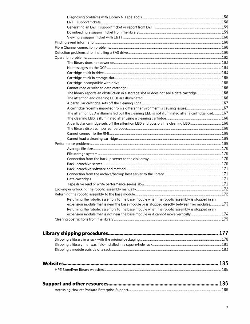
LTO-6 Fibre Channel tape drive back panel
1 2 3 4
1. Tape drive Ethernet port
2. FC port A
3. FC port B
4. Tape drive power LED, green
Overview 11

LTO-6 SAS tape drive back panel
1 2 3 4
1. Tape drive Ethernet port
2. SAS port A
3. SAS port B
4. Tape drive power LED, green
LTO-7 and LTO-8 Fibre Channel tape drive back panel
1 2 3 4
1. Tape drive Ethernet port
2. FC port A
3. FC port B
4. Tape drive power LED, green
LTO-7 and LTO-8 SAS tape drive back panel
1 2 3 4
12 Overview

1. Tape drive Ethernet port
2. SAS port A
3. SAS port B
4. Tape drive power LED, green
MSL3040 power supply LEDs
1 2
LED color Description
1 Green Module is powered on.
2 White AC power is connected.
Module and tape drive numberingModules and tape drives are numbered from the bottom of the library up, starting with the number one.
Example module numbering Example tape drive numbering
Module 3 Drive 5
(empty)
Drive 4
Module 2 (empty)
Drive 3
(empty)
Module 1 (empty)
Drive 2
Drive 1
MSL3040 storage slotsEach MSL3040 module has two magazines of storage slots that can be removed from the front of the library. Eachmagazine has 20 storage slots for tape cartridges.
Overview 13

The mailslot is in the right magazine. When enabled, the mailslot takes the place of storage slots 36-40.
Storage slot access for 40-slot robotic (Q6Q62B)
The robot is able to access all 40 storage slots within each module and there are no usage restrictions on the eight loweststorage slots in the library.
Storage slot access for 32-slot robotic (Q6Q62A)
The robot cannot access the lowest row of storage slots in the library. If the library only has a base module, the library willhave 32 storage slots. Each expansion module adds 40 storage slots.
If an expansion module is installed below the Q6Q62A base module, the inaccessible storage slots will be in the lowestexpansion module and all of the storage slots in the base module will be accessible.
The numbers associated with the inaccessible storage slots are not used. For example, storage slots 1 and 6, and mailslotMS1 are not visible in the RMI.
IMPORTANT: Do not install cartridges in any of the eight lowest storage slots in the library. If the library detectscartridges in the eight lowest slots, the amber Attention LED will flash and the library will post a Warning Eventcode 4126. The library will mark the cartridges as inaccessible and will not use them for backup operations. Removethe cartridges from the eight lowest slots to clear the Warning Event and turn off the flashing Attention LED.
EncryptionEncryption protects data from unauthorized access and use. The data is changed into a form that can only be read withthe key used to encrypt the data.
The LTO-4 and later generation tape drives can encrypt data while writing, and decrypt data when reading. Hardware-based data encryption can be used with or without compression while maintaining the full speed and capacity of the tapedrive and media. LTO tape drives use the 256-bit version of the industry-standard AES encrypting algorithm to protectyour data.
To use the tape drive hardware-based encryption feature, you need all the following:
• The “HPE 1/8 G2 Tape Autoloader and MSL Tape Libraries Encryption Kit” or a supported key server or a backupapplication that supports hardware-based data encryption.
• The KMIP feature license when using a KMIP key manager.
• LTO-4 or later generation media. The tape drive will not encrypt data when writing to LTO-3 or earlier generationmedia.
The tape drives can read encrypted data from and write encrypted data to some earlier generation media. The followingtable shows backward compatibility for encrypted data.
Table 1: Read and write compatibility for encrypted data
Media LTO-6 drive LTO-7 drive LTO-8 drive
LTO-4 media (encrypteddata)
Read only with encryptionkey
Incompatible Incompatible
LTO-5 media (encrypteddata)
Read/Write with encryptionkey
Read only with encryptionkey
Incompatible
LTO-6 media (encrypteddata)
Read/Write with encryptionkey
Read/Write with encryptionkey
Incompatible
Table Continued
14 Overview

Media LTO-6 drive LTO-7 drive LTO-8 drive
LTO-7 media (encrypteddata)
Incompatible Read/Write with encryptionkey
Read/Write with encryptionkey
LTO-8 media (encrypteddata)
Incompatible Incompatible Read/Write with encryptionkey
Your company policy will determine when to use encryption. For example, encryption might be mandatory for companyconfidential and financial data, but not for personal data. Company policy will also define how encryption keys aregenerated and managed. Backup applications that support encryption will generate a key for you.
HPE StoreEver 1/8 G2 Tape Autoloader and MSL Tape Libraries Encryption KitThe encryption kit provides secure generation and storage of encryption keys. The encryption kit can be used with anyStoreEver 1/8 G2 Tape Autoloader or MSL2024, MSL3040, MSL4048, and MSL6480 Tape Library with at least oneLTO-4 or later generation tape drive.
The encryption kit supports your manual security policies and procedures by providing secure storage for encryptionkeys. Access to the key server tokens and their backup files is protected with user-specified passwords. You will need tocreate processes to protect the tokens and secure the passwords.
Before enabling the encryption kit, verify that the library is running the most current firmware to ensure compatibilitybetween the token and library.
To use the encryption kit, insert a key server token in the USB port on the back of the library and then enable theencryption kit and configure the token from the RMI.
IMPORTANT: When encryption is enabled with the encryption kit, the library will not use encryption keys fromother sources, such as a key management system or application software. Disable encryption in applications writingto the library when encryption is enabled with the encryption kit. Applications that attempt to control encryptionwhile encryption is enabled with the encryption kit will not be able to do so, which can cause backups or other writeoperations to fail.
For information about configuring and using the encryption kit, see the HPE StoreEver MSL Tape Libraries EncryptionKey Server Configuration Guide, which is available from the Hewlett Packard Enterprise Information Library at http://www.hpe.com/info/storage/docs.
KMIP key manager integrationThe library supports integration with encryption key management servers using the KMIP standard. These keymanagement servers support sharing encryption keys with different tape libraries, which can be in different physicallocations.
Table 2: KMIP licenses
Part number License description
Q8K98A HPE StoreEver MSL3040 KMIP Key Manager LTU
Q8K98AAE HPE StoreEver MSL3040 KMIP Key Manager E-LTU
Use the Expert Partition Wizard to configure the use of a key manager. The library supports the use of one key managertype at a time. You can enable the configured key manager independently for each partition.
Data cartridgesLTO-3 and later generation tape drives support both rewritable and WORM data cartridges.
Overview 15

• Rewritable data cartridges are useful when you want to erase or overwrite the existing data, such as making periodicbackups or transferring data between libraries in different physical locations.
• WORM data cartridges protect data from accidental or malicious alteration of the data on the cartridge. An applicationcan append data after the existing data to use the full capacity of the data cartridge, but cannot erase or overwrite thedata on the cartridge. WORM data cartridges can be identified by their distinctive, two-tone cartridge color.
To determine whether your backup or archive software application supports WORM cartridges, see the Storage Mediawebsite: http://www.hpe.com/info/storagemedia.
LTO-7 Type M media for LTO-8 drivesThe library supports LTO-7 cartridges initialized as Type M media in LTO-8 tape drives. See the library firmware releasenotes for specific library firmware revisions that support LTO-7 Type M media.
Important notes for LTO-7 Type M media:
• When a new, unused LTO-7 cartridge has an ‘M8’ bar code label applied, it can be initialized as LTO-7 Type M media.
• Once an LTO-7 cartridge has been initialized to LTO-7 Type M media, the format is irreversible. Do not place an 'M8'bar code on an LTO-7 cartridge that has been previously used in an LTO-7 drive. A used LTO-7 cartridge cannot beinitialized as LTO-7 Type M media, even in an LTO-8 drive.
• LTO-7 Type M media provides up to 9 TB native capacity, instead of the 6 TB specified for LTO-7. As such, LTO-7Type M media can provide up to 22.5 TB with 2.5:1 compression (depending on the data being compressed.)
• LTO-7 Type M media support regular LTO features, including encryption, LTFS, and compression. LTO-7 Type Mmedia does not support WORM cartridges.
• LTO-7 Type M media are only compatible with LTO-8 tape drives. They are not compatible with LTO-7 drives and willnot be compatible with LTO-9 drives.
For more information about LTO-7 Type M media, see http://www.hpe.com/storage/storagemedia.
Guidelines for using and maintaining data cartridges
CAUTION: Do not degauss LTO data cartridges! The data cartridges are prerecorded with a magnetic servosignal, which is required to use the cartridges with LTO tape drives. Keep magnetically charged objects away fromdata cartridges.
To ensure the longest possible life for your data cartridges, follow these guidelines:
• Use only data cartridges designated for your library.
• Clean the tape drive when the Clean LED is illuminated.
CAUTION: Use only Ultrium universal cleaning cartridges.
• Do not drop a cartridge. Excessive shock can damage the internal contents of the cartridge or the cartridge case itself,making the cartridge unusable.
• Do not expose data cartridges to direct sunlight or sources of heat, including portable heaters and heating ducts.
• The operating temperature range for the library is 10ºC to 35ºC. The data cartridge storage temperature range is16ºC to 32ºC in a dust-free environment in which relative humidity is between 20% and 80% percent (noncondensing).For archival storage requirements, see the data cartridge specifications.
16 Overview

• If the data cartridge has been exposed to temperatures outside the specified ranges, stabilize the cartridge at roomtemperature for the same length of time it was exposed to extreme temperatures, or for 24 hours, whichever is less.
• Do not place data cartridges near sources of electromagnetic energy or strong magnetic fields such as computermonitors, electric motors, speakers, or x-ray equipment. Exposure to electromagnetic energy or magnetic fields candestroy data and the embedded servo code written on the media by the cartridge manufacturer, which can render thecartridge unusable.
• Place identification labels only in the designated area on the cartridge.
Write-protecting data cartridgesAll rewritable data cartridges have a write-protect switch to prevent accidental erasure or overwriting of data. Beforeloading a cartridge into the library, make sure the write-protect switch on the front of the cartridge is in the desiredposition.
Procedure
1. Slide the switch to the left to allow the library to write data to the cartridge.
1. Write-protect switch in the unlocked position
2. Write-protect switch in the locked position
3. Write-protect switch
4. Barcode label
5. Directional arrow. Insert the cartridge into the magazine with the arrow pointing into the storage slot.
2. Slide the switch to the right to write-protect the cartridge. An indicator, such as a red mark or small padlock, indicatesthat the cartridge is write-protected.
Read and write compatibilityHewlett Packard Enterprise Ultrium data cartridges are fully supported and compatible with all Ultrium tape products.Because Hewlett Packard Enterprise Ultrium media is Ultrium logo compliant, it can be used with any other tape drive thatbears the Ultrium logo.
LTO-6 drive LTO-7 drive LTO-8 drive
LTO-1 media Incompatible Incompatible Incompatible
LTO-2 media Incompatible Incompatible Incompatible
Table Continued
Overview 17

LTO-6 drive LTO-7 drive LTO-8 drive
LTO-3 media Incompatible Incompatible Incompatible
LTO-4 media — unencrypted Read only Incompatible Incompatible
LTO-4 media — encrypted Read only withencryption key
Incompatible Incompatible
LTO-5 media — unencrypted Read/Write Read only Incompatible
LTO-5 media — encrypted Read/Write withencryption key
Read only withencryption key
Incompatible
LTO-6 media — unencrypted Read/Write Read/Write Incompatible
LTO-6 media — encrypted Read/Write withencryption key
Read/Write withencryption key
Incompatible
LTO-7 media — unencrypted Incompatible Read/Write Read/Write
LTO-7 media — encrypted Incompatible Read/Write withencryption key
Read/Write withencryption key
LTO-7 Type M media — unencrypted Incompatible Incompatible Read/Write
LTO-7 Type M media — encrypted Incompatible Incompatible Read/Write withencryption key
LTO-8 media — unencrypted Incompatible Incompatible Read/Write
LTO-8 media — encrypted Incompatible Incompatible Read/Write withencryption key
Supported mediaUse Hewlett Packard Enterprise storage media to prolong the life of the library and tape drives. To learn more about, or topurchase media, see: http://www.hpe.com/storage/storagemedia
Table 3: Cleaning cartridge for all supported tape drives
Cartridge type Part number
HPE Ultrium universal cleaning cartridge (50 cleans), orange C7978A
Table 4: LTO-4 data cartridges
Cartridge type Part number
HPE LTO-4 Ultrium 1.6TB RW Data Cartridge, green C7974A
HPE LTO-4 Ultrium 1.6TB WORM Data Cartridge, two-tone (green and gray) C7974W
Table 5: LTO-5 data cartridges
Cartridge type Part number
HPE LTO-5 Ultrium 3 TB RW Data Cartridge, blue C7975A
HPE LTO-5 Ultrium 3 TB WORM Data Cartridge, two-tone (blue and gray) C7975W
18 Overview

Table 6: LTO-6 data cartridges
Cartridge type Part number
HPE LTO-6 Ultrium 6.25 TB MP RW Data Tape, purple C7976A
HPE LTO-6 Ultrium 6.25 TB BaFe RW Data Tape, purple C7976B
HPE LTO-6 Ultrium 6.25 TB MP WORM Data Tape, two-tone (purple and gray) C7976W
HPE LTO-6 Ultrium 6.25 TB BaFe WORM Data Tape, two-tone (purple and gray) C7976BW
Table 7: LTO-7 data cartridges
Cartridge type Part number
HPE LTO-7 Ultrium 15 TB RW Data Tape, blue C7977A
HPE LTO-7 Ultrium 15 TB WORM Data Tape, two-tone (blue and gray) C7977W
Table 8: LTO-7 Type M media for LTO-8 drives
Cartridge type Part number
HPE LTO-7 Ultrium Type M 22.5 TB RW Custom Labeled Data Cartridges (20 pack) Q2078ML
HPE LTO-7 Ultrium Type M 22.5 TB RW Non-Custom Labeled Data Cartridges (20 pack) Q2078MN
Table 9: LTO-8 data cartridges
Cartridge type Part number
HPE LTO-8 Ultrium 30 TB RW Data Tape, green Q2078A
HPE LTO-8 Ultrium 30 TB WORM Data Tape, two-tone (green and gray) Q2078W
HPE Command View for Tape LibrariesHPE Command View for Tape Libraries (CVTL) is a single pane of glass management platform for users to manage,monitor, and configure all their tape libraries through a single console. It saves time by performing daily management andtroubleshooting tasks from one location. CVTL also provides remote management, diagnostics, and configuration for allMSL Tape Libraries located across the room or across the globe.
Key features:
• View health summaries for the entire library environment
• View library and autoloader utilization by slots, media, and drives
• Search for media by barcode label
• Upgrade firmware for all libraries in an entire library environment
• View persistent event logs and drive support tickets for an entire library environment
Command View for Tape Libraries is also the centralized location for TapeAssure Advanced and Data Verificationfunctionality. For more information, see http://www.hpe.com/support/cvtl.
For information on installing and using CVTL, see the HPE StoreEver Interface Manager and Command View for TapeLibraries user guide, available from the Hewlett Packard Enterprise website at http://www.hpe.com/support/cvtl.
Overview 19
Command View for Tape Libraries support is included in all MSL3040 library firmware. To find and download the most up-to-date firmware revision, visit the Hewlett Packard Enterprise support website at http://www.hpe.com/support/hpesc.
HPE StoreEver TapeAssure AdvancedThe MSL3040 is available with HPE StoreEver TapeAssure Advanced - analytics software with automated, predictivemonitoring of health and performance of tape drives and cartridges. TapeAssure Advanced reporting and analysisfeatures allow users to get the most out of their investment by knowing how their library is being used. HPE StoreEverTapeAssure Advanced Software is fully integrated with HPE StoreEver Command View for Tape Libraries, providing anintuitive, easy-to-use dashboard for analysis of performance, health, and utilization of tape drives and cartridges.
TapeAssure Advanced analytics features use predictive forecasting to anticipate the likelihood of bottlenecks, failures,and load balancing issues in the tape library environment. Analysis of drive and tape utilization helps users understandavailable capacity and performance which helps to plan.
For more information about TapeAssure Advanced, see: http://www.hpe.com/storage/tapeassure
NOTE: HPE StoreEver TapeAssure Advanced Software is licensed by tape library; one license is required for each tapelibrary
HPE Data VerificationHPE StoreEver Data Verification Software proactively validates and scans, nondisruptively, the quality of data stored onLTO tape cartridges. Ensure that critical business data can be restored when needed by scanning and validatinginfrequently accessed tapes.
StoreEver Data Verification Software is fully integrated into the HPE StoreEver Command View for Tape LibrariesSoftware. This integration provides a single-pane-of-glass management platform.
Key features:
• Scan infrequently accessed LTO tapes to verify health of tape cartridges as well as the data stored on those tapes.
• Improve reliability and reduce the risk of restore failure.
• Scanning without interrupting host applications.
• Protect all tape cartridges, active and vaulted archived media, with the same license (per 100 cartridge slots).
• Receive advanced notification for needed media migration.
• Fully integrated with Command View for Tape Libraries.
Business benefits
• Ensures that critical business data can be restored when most needed.
• High Availability - No impact to backup operations.
• Ease of Use - Single license for 100 cartridge slots.
• Save Money - Migrate data only when necessary.
HPE StoreEver Data Verification Software is only supported and licensed on the MSL3040 and MSL6480 tape libraries.One license is required per 100 cartridge slots.
For more information about Data Verification, see http://www.hpe.com/storage/dataverification.
20 Overview

Connecting cables for Data VerificationTo configure the library for Data Verification, create a private network for the library and the tape drives that will be usedfor Data Verification.
Procedure
1. If necessary, install a switch with enough Ethernet ports for the library and the tape drives that will be used for DataVerification.
For example, if two tape drives will be used for Data Verification, the switch must have at least three available ports.
2. Using an Ethernet cable, connect the library DIAG port to the switch.
1 2
3
1. Tape drive Ethernet ports are connected to the private network for the Data Verification feature.
2. Library DIAG port is connected to the private network for the Data Verification feature.
3. Library Ethernet port is connected to the site LAN to provide user access through the RMI.
3. Using Ethernet cables, connect each tape drive that will be used for Data Verification to the switch.
4. Regardless of whether you are using a dedicated switch or a VLAN for the data verification network, ensure that onlythe drive Ethernet ports and the DIAG port are connected to the private network, and that no other hosts or devicesare sharing the network.
5. Verify that the tape drive SAS or FC ports are NOT connected.
Path failover featuresThe library supports data path failover and control path failover with LTO-6 and later generation tape drives.
• Data path failover—Both tape drive ports are connected to the SAN. Only one of the ports is used at any one time andthe second port is a standby port. When a link failure on the active port is detected, the second port is used. Data pathfailover requires a dual-port drive.
• Control path failover—Depending on the drive, one or both ports on the control path drive are configured to present apath to the library controller and a second drive is configured as a standby library control path drive.
Path failover implementations
Path failover uses features built into the library and tape drive firmware and also use operating system drivers. The librarysupports two path failover implementations, which are presented in the library user interface as:
• Advanced failover
Overview 21

◦ Is only supported with LTO-6 FC tape drives.
◦ Requires host driver features, along with tape drive and library firmware features.
◦ Manages multiple paths across multiple SANs, presents a single drive or library path to applications, and transferscommands automatically to the new path if the original path is lost.
◦ The transfer to the failover path is invisible to most applications, avoiding the need for user intervention.
◦ Requires the LTO-6 failover license.
• LTO-7+ failover
◦ Is only supported with LTO-7 and later generation FC tape drives.
◦ Requires host driver features, along with tape drive and library firmware features.
◦ Manages multiple paths across multiple SANs, presents a single drive or library path to applications, and transferscommands automatically to the new path if the original path is lost.
◦ The transfer to the failover path is invisible to most applications, avoiding the need for user intervention.
◦ Requires the LTO-7+ failover license.
Path failover feature licensing
Failover features are licensed and can only be enabled after the applicable license has been added to the library.
• LTO-6 High Availability path failover: Separate licenses are available for control path failover and data path failover.
• LTO-7+ failover: A single license supports both control path failover and data path failover.
Path failover licenses
Table 10: Failover licenses for LTO-6 drives
Part number License name
Q8K96A HPE StoreEver High Availability MSL3040 LTO-6 Control Path Failover LTU
Q8K96AAE HPE StoreEver High Availability MSL3040 LTO-6 Control Path Failover E-LTU
Q8K97A HPE StoreEver High Availability MSL3040 LTO-6 Data Path Failover LTU
Q8K97AAE HPE StoreEver High Availability MSL3040 LTO-6 Data Path Failover E-LTU
Table 11: Failover licenses for LTO-7 and later generation drives
Part number License name
Q8L00A HPE StoreEver MSL3040 LTO-7+ Path Failover LTU
Q8L00AAE HPE StoreEver MSL3040 LTO-7+ Path Failover E-LTU
Path failover configuration and status
Control path and data path failover are configured and enabled with the expert partition wizard.
Control path failover is configured independently for each partition. The configuration settings are displayed on theStatus > Partition Map > Configuration Status screen.
22 Overview

Data path failover is configured for a tape drive. The configuration settings are displayed in the Status > Drive Statusscreen.
Failover documentation
HPE StoreEver Tape Libraries LTO-5 and LTO-6 Failover User Guide and the HPE StoreEver Tape Libraries LTO-7+Failover User Guide on the Hewlett Packard Enterprise website at http://www.hpe.com/info/msl.
Secure ManagerWith Secure Manager, you can configure hosts and drives into access control groups that are managed by the library. WithSecure Manager enabled, the drives are not visible to hosts that are logged in to the SAN and so the host will not see thedrives by default. For the host to see a drive, the host must be configured into an access control group with the drive.
Secure Manager only supports FC drives; SAS drives are not supported. The RMI displays unsupported drives with graytext. The only Secure Manager function you can perform on the unsupported items is to change the name of a SAS host.
To use Secure Manager, you must understand your FC environment and which hosts to group with which drives. OnceSecure Manager is enabled, you will not see drives or libraries from hosts that are outside their group. Without SecureManager enabled, a host will see a drive as soon as the link is up.
Secure Manager is a licensed feature and can only be enabled after the license has been added to the library.
Table 12: Secure Manager licenses
Part number Description
Q8K99A HPE StoreEver MSL3040 Secure Manager LTU
Q8K99AAE HPE StoreEver MSL3040 Secure Manager E-LTU
Overview 23

Installing the library
WARNING: Each library module weighs 20 kg (44 lb) without media or tape drives and at least 35 kg (77 lb) withmedia (40 cartridges) and three tape drives. When moving the library, to reduce the risk of personal injury ordamage to the device:
• Observe local health and safety requirements and guidelines for manual material handling.
• Remove all tapes to reduce the overall weight of the device and to prevent cartridges from falling into therobotic path and damaging the library. Keep the cartridges organized so they can be returned to the samelocations.
• Obtain adequate assistance to lift and stabilize the device during installation or removal.
WARNING: When placing the library into a rack, to reduce the risk of personal injury or damage to equipment:
• Extend the rack leveling jacks to the floor.
• Ensure that the full weight of the rack rests on the leveling jacks.
• Install the rack stabilizer kit on the rack.
• Extend only one rack component at a time. Racks may become unstable if more than one component isextended.
CAUTION: Slide/rail mounted equipment is not to be used as a shelf or a work space.
IMPORTANT: Verify that the rack is level front to back and side to side before installing a module into the rack.Racks that are not level can prevent the modules from aligning properly.
Tools required:
Small flat head and #1 Phillips screwdrivers
Planning the installation
Procedure
1. Choose a location for the library.
Location requirements
2. Plan the rack layout.
Module and rack layout guidelines
3. Plan the SAS or Fibre Channel configuration and obtain the necessary cables.
• FC connection information
• SAS connection information
4. Library partition guidelines
24 Installing the library

Location requirementsThe library must be installed in a supported rack on the provided rack shelves. Select a location with access to the hostserver that meets the location requirements.
Table 13: Location requirements
Criteria Definition
Rack requirements HPE G2 Enterprise Series, Enterprise Series, G2 Advanced Series, Advanced Series,Standard Series, and other HPE square hole or round hole racks
Rack space requirements 3U for the base module and 3U for each expansion module
Room temperature 10-35º C (50-95º F) for the tape library. Some tape drives have a more limitedtemperature range when operating at high altitudes. Verify the tape drive operatingrequirements before installing a tape drive in a high altitude environment.
Power source • AC power voltage: 100-240 VAC
• Line frequency: 50-60 Hz
• Library located near AC outlet(s)
The AC power cord is the library’s main AC disconnect device and must be easilyaccessible at all times.
Air quality • Place the library in an area with minimal sources of particulate contamination.
• Avoid areas near frequently used doors and walkways, stacks of supplies thatcollect dust, printers, and smoke-filled rooms.
• Excessive dust and debris can damage tapes and tape drives.
Humidity 20-80 percent RH non-condensing
Module and rack layout guidelinesWhen possible, install the base module near the middle of the rack at a convenient height for viewing and operating theOCP and accessing the mailslot.
The library supports up to 3 expansion modules above and 3 expansion modules below the base module, for a total of 7modules. Each module occupies 3U.
For maximum library expansion, install the base module as the centered module of the rack, allowing 9U above the top ofthe base module and 9U below the bottom of the base module.
If the library will be sharing the rack with other equipment, place heavy devices, such as disk arrays, in the bottom of therack to reduce the chance of the rack tipping.
FC connection informationConnect the FC tape drive directly to the server with an HBA or indirectly through a SAN with an FC switch.
Installing the library 25

Table 14: FC drive interface speeds
LTO generation Supported speeds
LTO-6, LTO-7, LTO-8 2 Gb, 4 Gb, 8 Gb
Most supported tape drives have two FC ports. Only one port can be used at a time, but both ports can be connected forpath failover or with software that supports multipath. If you are using only one port, you can use either port. Path failoveris a licensed library feature.
Direct connection
The host must have a 2 Gb, 4 Gb, 8 Gb, or 16 Gb FC HBA. A 4 Gb HBA is recommended for LTO-4 tape drives. An 8 Gb orfaster HBA is recommended for LTO-5 and later generation tape drives. To verify that an HBA is supported on yourserver and qualified for the tape drive, see the compatibility matrix at: https://www.hpe.com/storage/StoreEverSupportMatrix
A server that has FC-attached hard drives performs best with at least two FC ports. Using the same FC port for disk andtape drive access can cause performance degradation.
SAN connection
All switches between the host and the tape drive must be of the appropriate type. A 2 Gb switch in the path might causeperformance degradation when backing up highly compressible data.
Configure zoning on the FC switch so that only the backup servers can access the tape drive. For more information, seethe switch documentation.
Cable requirements
An FC cable is required for each FC port you plan to use. The tape drive has an LC-style connector. The maximum cablelength is based on the tape drive and external cable type.
Cable type 2 Gb 4 Gb 8 Gb
OM2 0.5 – 300 m 0.5 – 150 m Not supported
OM3, OM4 0.5 – 500 m 0.5 – 380 m 0.5 – 150 m
SAS connection informationThe server must have a SAS host bus adapter with an external connector.
Table 15: SAS drive interface speeds
LTO generation Supported speeds
LTO-6, LTO-7, LTO-8 1.5 Gb, 3 Gb, 6 Gb
The library uses two SCSI logical unit numbers (LUNs) and requires an HBA with multiple LUN support. Most HewlettPackard Enterprise SAS RAID controllers support tape devices; many other SAS RAID controllers do not support tapedevices. To verify the specifications of your HBA or find a list of compatible HBAs, see the compatibility matrix at: https://www.hpe.com/storage/StoreEverSupportMatrix
CAUTION: Do not connect the library to a SAS RAID controller unless the compatibility matrix shows that thecontroller is qualified with the library. The server might not be able to boot when the library is connected to anunsupported SAS RAID controller.
26 Installing the library

About SAS
SAS is a computer bus technology for transferring data to and from storage devices, including disk drives and tape drives.SAS-1, which is used for LTO-4 tape drives, is designed to transfer data at 3 Gb/s. SAS-2, which is used for LTO-6 andlater generation tape drives, is designed to transfer data at 6 Gb/s.
CAUTION: Reliable data transfer requires high-quality cables and connections.
• Always verify that the SAS cable is rated for the data transfer speed of the HBA and tape drive.
• Do not use adapters or converters between the HBA and the tape drive. SAS signal rates require cleanconnections and a minimum number of connections between the HBA and the tape drive.
• SAS cables described as "equalized" might not support 6 Gb/s data rates. Do not use equalized cables withLTO-6 or later generation tape drives unless these cables are verified for 6 Gb/s data rates.
• For optimal performance, only use cables of the length specified as qualified for your products. Do not use aSAS cable longer than 6 meters.
Cable requirements
SAS uses serial connections, with a direct connection between the host server and each of the storage devices. Thismethod eliminates the need to configure SCSI buses and assign SCSI IDs, as is required for parallel SCSI devices.
Most SAS HBA ports have four SAS channels. A tape drive uses one channel, so each HBA port can support up to fourtape drives. You can use a cable with one connector on each end, but only one channel will be used. The SAS fanout cablerecommended for use with the library can connect up to four SAS tape drives to a single SAS HBA port.
Figure 1: Example SAS fanout cable
Connectors
The host end of the cable must have the same type of connector as the HBA external SAS port.
The tape drive has a mini-SAS connector. The connector is keyed in location 4, which is the standard location for enddevices. If you use a cable other than the one recommended for use with the product, verify that it is keyed in location 4.
CAUTION: Mini SAS connectors are keyed. Do not force a SAS cable mini-SAS connector into the tape drive mini-SAS port because it might be keyed differently.
World Wide identifiers
A unique identifier called a World Wide Name (WWN) or World Wide Identifier (WWID) identifies a SAS tape drive. Thelibrary assigns the World Wide identifier to the drive bay. When a tape drive is replaced, the World Wide identifier isreassigned to the new tape drive.
Installing the library 27

The operating system tracks the World Wide identifier for the drive on each HBA channel. Each of the drive connectors ona fanout cable is associated with an HBA channel. Once a drive has been connected, keep it on the same channel to retainthe association between the HBA channel and World Wide identifier.
Library partition guidelines
Partition constraints
The library has a flexible partitioning scheme with the following constraints:
• Each partition must have at least one tape drive. One tape drive in each partition hosts the library LUN for thepartition.
• The maximum number of partitions is 21.
• Magazine slots are allocated to partitions in five-slot groups, except for a 32-slot library (Q6Q62A), in which case theslots may be in four or five slot groups depending on whether the magazine slots are located in the bottom module ornot.
• Mailslots must be enabled for a module before they can be allocated to a partition.
A partition does not need to have a mailslot. If a partition does not have a mailslot, the magazine must be accessed toimport or export cartridges. Opening a magazine takes the library off line.
Although the mailslot magazine is shared between partitions, the mailslot elements are assigned individually topartitions.
Partition wizards
Wizards guide you through the partition configuration process. The wizards are only accessible from the RMI.
• Basic Partition Wizard – You specify the number of partitions. The wizard removes the current partitionconfiguration and assigns the drives and storage slots as evenly as possible to the partitions. Any extra drives or slotsare assigned to the first partition.
Use the Basic Partition Wizard to configure partitions that will have similar resources. For a library with a singlepartition, use the Basic Partition wizard to configure the number of barcode characters to report to the hostapplication and whether to report them from the left or right end of the label.
• Expert Partition Wizard – You add or remove partitions from the current partition configuration and then edit eachpartition configuration to add or remove library resources.
Use the Expert Partition Wizard to configure partitions that will have different resources or to adjust resourceassignments for existing partitions or partitions created with the Basic Partition Wizard.
CAUTION: The library goes off line while partitions are being configured. Ensure that all host operations are idlebefore running a partition wizard.
Preparing the host
CAUTION: Parts can be damaged by electrostatic discharge. Keep parts in electrostatic containers until needed.Ensure that you are properly grounded when touching static sensitive components.
28 Installing the library
Procedure
• Check with a system administrator before powering off the host computer.
• For a library with SAS drives, confirm availability or install a SAS HBA that supports multiple LUNs.
• For a library with direct-attach Fibre Channel drives, confirm availability or install an FC HBA.
• For a library with Fibre Channel drives connected through a compatible switch, verify that sufficient ports areavailable.
Unpacking the shipping containers
Prerequisites
Before unpacking any modules, clear a level work surface near where you will install the modules.
CAUTION: If the temperature in the room where the module will be installed varies by 15º C (30º F) from the roomwhere it was stored, allow the module to acclimate to the surrounding environment for at least 12 hours beforeunpacking it from the shipping container.
NOTE: If you are installing a library with multiple modules and have limited work space, locate and unpack the basemodule first, along with the rack shelves and accessory kits for all of the expansion modules.
Procedure
1. Before opening and removing a module from the box, inspect the container for shipping damage.
If you notice any damage, report it to the shipping company immediately.
2. Unpack the module and accessories from the box, one layer at a time. Place the module on a work table.
3. Remove the protective foam insert from the base module. This step does not apply to expansion modules.
The robotics is protected during shipment by a foam insert that must be removed before installation.
IMPORTANT: To avoid personal injury or damage to the module, always support the bottom of the modulewhere the rack shelf contacts the module. Do not touch internal mechanical or electrical components whilemoving the module.
Installing the library 29

1 2
3
a. Use two small screwdrivers to unlock the top cover.
b. Lift the cover front end by about 12 cm and pull gently forward to disengage from the pivot point at the modulecenter.
c. Remove the foam insert.
4. If you are installing a base module only without an expansion module or the base module will be the top module in thelibrary, replace the top cover on the base module.
12
5. If you are installing a library with an expansion module above the base module, keep the top cover with the basemodule until the cover is installed on the top expansion module.
6. Save the packaging materials for future use.
Installing the shelves in the rackEach module is supported by a pair of shelves and is secured to the rack with captive fasteners.
30 Installing the library

For easier installation when installing a library with multiple modules, install all the shelves before installing any of themodules.
Prerequisites
• Rackmount accessory kit for each module containing:
◦ Four adapter blocks
◦ Four Phillips screws
◦ Two rack shelves, one for each side of the rack, labeled LHS and RHS
• #3 Phillips screwdriver
Procedure
1. When installing multiple modules, locate the shelf locations for all modules.
a. Locate the bottom of the lowest full U where the lowest module will be installed.
b. Count up the rack 3U for each module until all the module locations are identified.
2. From the front of the rack, mount an adapter block at the appropriate height for each module on the front rack posts.
a. Orient the adapter block for your rack.
1 2
1. Orientation for a square-hole rack. The face with square inserts is installed into the square rack holes.
2. Orientation for a round-hole rack. The face with the round inserts is placed against the rack posts.
b. Align the adapter block in the bottom 2U of the 3U volume that the module will occupy, as shown in theillustration.
Installing the library 31

1
2
c. Secure the adapter block with a Phillips screw from the accessory kit.
3. From the rear of the rack, mount an adapter block at the same height as each corresponding front adapter block.
4. From the front of the rack, starting at the rear adapter, mount the LHS rack shelf for each module into the adapterblocks on the left side of the rack.
3
1
2
5. From the front of the rack, starting at the rear adapter, mount the RHS rack shelf for each module into the adapterblocks on the right side of the rack.
6. Ensure that each rack shelf tab is properly engaged with the front and rear adapters. Verify that the rack shelf cannotmove in the front-to-back axis of the rack.
32 Installing the library

Installing the base module in the rack
Prerequisites
#2 Phillips screwdriver
Procedure
1. If the top cover is not installed on the base module, set it aside on the work table.
2. From the front of the rack and while supporting the bottom of the module in the areas supported by the rack shelves,set the back of the base module on the front of the shelves.
3. Push the base module into the rack until the front of the module contacts the front rack posts.
1
2
4. Use a #2 Phillips screwdriver to tighten the captive fasteners on each side of the base module until they are fingertight. Do not over tighten.
5. Verify that the module is contained within the 3U rack volume.
Preparing the top and bottom modulesSkip this step if you are installing a base module only, without any expansion modules.
The base module has removable top and bottom cover plates.
Procedure
1. If an expansion module will be installed above the base module, move the top cover plate from the base module to thetop of the expansion module that will be installed at the top of the library.
2. If an expansion module will be installed below the base module, move the bottom cover plate from the base module tothe bottom of the expansion module that will be installed at the bottom of the library.
Installing the library 33

Moving the top cover plate
Procedure
1. Remove the top cover plate from the current module.
1 2
3
a. Unlock the top cover using two small screwdrivers.
b. Lift the cover front end by about 12 cm.
c. Gently pull the cover forward to disengage from the pivot point at the module center.
2. Install the cover plate on the other module.
a. With the front of the top cover raised approximately 12 cm, engage the rear of the cover at the module pivot pointlocated at the back of the opening.
12
b. Lower the front of the cover until the latches engage on both sides.
34 Installing the library

Moving the bottom cover plate
Procedure
1. Remove the bottom cover plate from a module.
a. If the module is not installed in a rack with access to the bottom, lift the module front end by about 16 cm, usingthe rear of the module as a pivot point.
You will need someone to hold the module while you remove the bottom cover plate.
b. Support the bottom cover with one hand. Insert a small flathead screwdriver or Torx screwdriver into the slot andslide about 4 mm sideways to unlock the spring loaded lock.
1
2
3
4
c. Lower the cover front end by about 10 cm and pull gently forward to disengage from the cover pivot point atmodule center.
d. Remove the cover from the module.
2. Install the bottom cover plate on the other module.
2
1
Installing the library 35

a. Place the module upside-down on a work table.
b. Insert the back of the cover at the module center.
c. Lower the cover front edge until you feel a hard stop and the cover locks in at the front of the module.
Installing the expansion modules in a rackSkip this step if the library does not have expansion modules.
TIP: When installing multiple expansion modules, work from the base module to the top of the library and then fromthe base module to the bottom of the library.
Prerequisites
• The rack shelves are installed.
• The library cover plates are on the modules that will be on the top and bottom of the library.
Procedure
1. From the front of the rack while supporting the bottom of the module in the areas supported by the rack shelves, setthe back of the expansion module on the front of the rack shelves. Push the module into the rack until the front of themodule contacts the rack posts.
2. Verify that this module has been installed directly above or below its adjacent module and is contained with thecorrect 3U volume.
The gap between modules must be less than 4mm.
3. Use a #2 Phillips screwdriver to tighten the captive fasteners on each side of the expansion module until they arefinger tight. Do not over tighten.
4. Repeat for any other expansion modules.
5. Verify that the top cover plate is at the top of the library and that the bottom cover plate is at the bottom of thelibrary.
Aligning and connecting modulesSkip this step if the library does not have expansion modules.
Procedure
1. From the front of the library, loosen the screws on each of the modules two full turns.
2. From the back of the library, starting with the bottom pair of modules, align each module with the module below.Repeat for each pair of adjacent modules.
a. Lock the alignment mechanism.
If the alignment mechanism has a lock, slide the lock to the left, move the alignment mechanism to the lockedposition, and then release the spring-loaded lock.
36 Installing the library

1
2
If you encounter resistance, adjust the position of the upper module so the pin in the alignment mechanism movesinto the mating hole in the lower module.
3. Verify that the lowest module in the library has its alignment mechanism in the unlocked position.
4. From the front of the library, use a #2 Phillips screwdriver to tighten the captive fasteners on each side of all of themodules until the fasteners are finger tight. Do not over tighten.
5. From the back of the library, connect each adjacent pair of modules with expansion interconnect cables, if not alreadyconnected.
Installing the library 37

Installing optional power suppliesEach module supports up to two power supplies. The base module is shipped with one power supply installed. Expansionmodules are shipped without a power supply.
If an expansion module will have one or more tape drives, it must have a power supply.
When present and connected to a different AC power source, the second power supply in the module providesredundancy.
Procedure
1. Using a #2 Phillips screwdriver, remove the power supply bay cover.
When installing the first power supply in an expansion module, the power supply can be installed in either bay.
2. Position the new power supply on the alignment rails.
3. Slide the power supply into the module until it is flush with the back panel of the module.
1
2
4. Tighten the blue captive thumbscrews with your fingers or a #2 Phillips screwdriver until it is finger tight. Do not overtighten.
Installing tape drivesWhen possible, install all tape drives during the initial library installation process before the library is powered on. Wheninstalling additional tape drives after the library has been powered on, follow the instructions included with the tape drive.
TIP: To assist in aligning the drive, only remove the drive bay covers for one drive at a time.
CAUTION: All drive bays without tape drives installed must have drive bay covers installed.
Procedure
1. Locate an appropriate vacant drive bay on the back of the library.
38 Installing the library

NOTE: A full-height drive can only be installed in the bottom two half-height drive bays. A full-height drive cannot beseated in other locations and will not operate. If the drive will not seat completely, verify that it is located in the correctdrive bays.
2. Remove the face plate covering the drive bay by removing the screws holding it in place.
Remove one drive bay cover to install a half-height tape drive; remove two drive bay covers to install a full-height tapedrive.
3. Holding the tape drive by the handle and supporting it from the bottom, slide the tape drive along the alignment railsinto the drive bay until it is flush with the back of the library.
2
1
4. To secure the tape drive to the chassis, use a torque driver to tighten the blue captive thumbscrews on the drive sledto 6 inch pounds or 0.68 N m.
If a torque driver is not available, use a #2 Phillips screwdriver to tighten the thumbscrews until a low initial thresholdtorque achieves a snug tight condition.
If the thumbscrews cannot be tightened, verify that the tape drive is aligned properly.
Connecting the Fibre Channel cables
NOTE: Using both ports on a dual-port drive requires multipath capability in the host application. For information aboutconfiguring the second port, see the application documentation.
Procedure
1. Remove the FC port caps if necessary. Attach one end of the FC cable to port A on the tape drive.
2. Attach the other end of the FC cable to a switch or HBA.
Connecting the SAS cable
NOTE: SAS signal rates require clean connections between the HBA and tape drive. Do not use adapters or convertersbetween the HBA and the tape drive. For reliable operation, use a maximum SAS cable length of six meters.
Installing the library 39

Procedure
1. Attach the HBA end of the SAS cable into the connector on the HBA. If you are using a SAS fanout cable, the end ofthe cable with only one connector should be plugged into the HBA.
2. Connect the drive end of the cable.
• When using a cable with a single connector on each end, attach the other end into the connector on the tape drive.
• When using a SAS fanout cable, attach one mini-SAS connector into the connector on each tape drive. The unusedends of the SAS fanout cable are single channel and not suitable for use with disk arrays. Use the other ends toconnect tape drives, or coil and secure them to the rack to minimize stress on the connectors.
TIP: When using a SAS cable not specified for the library, do not force a SAS cable's mini-SAS connector into thetape drive mini-SAS connector because it might be keyed differently.
NOTE: Each of the tape drives uses one channel and the fanout cable recommended for use with the library maps eachof the four channels from the HBA to one channel on the drive end.
You can plug any of the four drive connectors into any tape drive.
Powering on the library
Procedure
1. Plug the power cables into the power connectors on each module and into power outlets.
TIP: If a module has two power supplies, plug each power cord into a different AC power circuit to increaseredundancy.
2. To use the RMI, connect an Ethernet cable from MGMT Ethernet port on the base module controller to your network.
3. Power on the library by pressing the power button on the base module just under the OCP. The green light and OCPwill illuminate.
When the library is powered on, it performs the following procedures:
• Inventory the tape cartridges in the magazines
• Check the firmware version on all modules
• Configure the tape drives
• Confirm the presence of the existing modules
• Search for any new modules
Initiating the configuration wizard
Procedure
1. Log in to the OCP as the administrator user.
40 Installing the library

The initial configuration wizard starts upon first login.
2. Follow the instructions in the wizard to configure the network, date, and time settings, and set the INITIAL RMIadministrator password.
The INITIAL RMI administrator password is a four-digit PIN that is set from the OCP.
3. Log in to the RMI as the administrator user.
Use the INITIAL RMI administrator password that was set from the OCP to log in to the RMI the first time.
The library will prompt you to set an actual RMI administrator password. If one person physically installs the libraryand a second person will configure the library using the RMI, share the INITIAL RMI administrator password asappropriate.
4. Navigate to Configuration > Configuration Wizard from the RMI to complete the library configuration.
Verifying the host connections
Procedure
1. Install the application software and/or drivers that are compatible with the library.
Backup software packages might require additional software or licensing to communicate with the robotics.
For compatibility information, see the compatibility matrix at: https://www.hpe.com/storage/StoreEverSupportMatrix
2. Verify the connection between the library and the host using the host server operating system utilities or Library andTape Tools (L&TT).
L&TT verifies that the unit is connected and communicating with the host server. It also verifies that the device isfunctioning and provides diagnostic information. L&TT is available without charge at: http://www.hpe.com/support/TapeTools
Configuring the FC interface
PrerequisitesThe administrator password.
Procedure
1. Log in to the RMI and enter the administrator password if requested.
2. Navigate to the RMI Configuration > Drives screen.
3. Configure the settings for your drive and connection method.
Drives connected to a SAN
Leave the FC port at the default settings of Port Speed: Automatic and Port Type: Automatic. With these settings,the tape drive will use the appropriate configuration.
Drives connected directly to the host
Installing the library 41

• When using LTO-7 and LTO-8 drives with a 32Gb or 16Gb HBA in direct attach mode, Port Type should typicallybe set to Fabric Mode. Early (Gen5) 16Gb and 8Gb/4Gb host adapters may require the topology to be set to LoopMode.
• For LTO-6 drives, leave the FC port at the default settings of Port Speed: Automatic and Port Type: AutoDetect. With these settings, the tape drive will use the appropriate configuration.
4. Click Submit.
Labeling tape cartridgesUsing unlabeled media can significantly increase the inventory scan time and is therefore not recommended for normaloperation.
Procedure
Apply a high-quality preprinted bar code label to each tape cartridge.
LTO tape cartridges have a recessed area on the face of the cartridge next to the write-protect switch. Use this area forattaching the adhesive-backed bar code label.
Loading tape cartridgesThe library will power on without tape cartridges. However, the library needs cartridges before performing data read orwrite operations, or any tests or operations that transfer cartridges.
Procedure
1. Open a magazine.
a. From the OCP, navigate to the Open Magazine/Mailslot > Open Magazine screen.
The library lights the magazine release button for each magazine in the library.
b. Press the magazine release button for the magazine to be opened.
The library will release the lock.
c. Pull the magazine straight out of the library, supporting the bottom with your hand.
NOTE: If the magazine has not been extended or removed from the library within 30 seconds, the library will relockthe magazine.
2. Load the cartridges.
Insert one or more labeled cartridges into the storage slots in the magazine.
NOTE: 32-slot (Q6Q62A) only—Do not install cartridges in any of the eight lowest storage slots in the library. If thelibrary detects cartridges in the eight lowest slots, the amber Attention LED will flash and the library will post aWarning Event code 4126. The library will mark the cartridges as inaccessible and will not use them for backupoperations. Remove the cartridges from the eight lowest slots to clear the Warning Event and flashing Attention LED.
3. Insert the magazine into the magazine slot.
42 Installing the library

When reinstalling the magazines, ensure that the guides at the top and bottom of the magazine are correctly engaged.
The library waits 10 seconds after a magazine has been reinserted before starting the inventory process. During thistime, press a magazine release button to release another magazine. If another magazine release button is not pressedduring those 10 seconds, the library locks all magazines and starts the inventory process.
Verifying the installation
IMPORTANT:
• The library will only operate with both top and bottom library cover plates installed.
• Do not place anything on the top library cover plate, the weight may cause errors in the library operation.
• Do not allow anything to contact the bottom library cover plate, contact may cause errors in the libraryoperation.
Procedure
1. Verify that the library and drives have the current firmware revision.
The library firmware revision is displayed in the top left corner of the OCP and RMI screen.
The drive firmware version is displayed on the RMI Status > Drive Status screen and the OCP Status > Drive screen.
2. If necessary, update the library firmware from the OCP or RMI Maintenance > Firmware Upgrades > SystemFirmware screen.
3. After configuring the library, you can save the configuration settings to a USB flash drive from the OCP Configuration> Save/Restore > Save Configuration File or to a file on your computer from the RMI Configuration > System >Save/Restore screen.
Having a backup of the library configuration is helpful when recovering from a configuration error or if the libraryneeds service.
4. Set the security user password from the Configuration > User Accounts screen.
Downloading product firmware
Procedure
1. Navigate to the HPE Support website: http://www.hpe.com/support/storage
IMPORTANT: Access to some updates might require product entitlement when accessed through the HewlettPackard Enterprise Support Center. You must have an HPE Passport set up with relevant entitlements.
To view and update your entitlements, and to link your contracts and warranties with your profile, navigate to: http://www.hpe.com/support/AccessToSupportMaterials
2. Browse or search for the necessary firmware.
3. Download the firmware.
To upgrade firmware from the OCP, copy the firmware image onto a FAT-32 formatted USB flash drive.
Installing the library 43

Configuring additional featuresThe library has many features to customize it for your organization.
Procedure
• Enabling the mailslot.
• Configuring partitioning and additional library parameters using one of the partitioning wizards.
◦ Basic Partition Wizard — Use the Basic Partition Wizard to configure partitions that will have similar resources orto configure the number of bar code characters to report to the host application and whether to report them fromthe left or right end of the label for a library with a single partition.
◦ Expert Partition Wizard — Use the Expert Partition Wizard to configure partitions that will have different resourcesor to adjust resource assignments for existing partitions or those partitions created with the Basic Partition Wizard.
• Modifying the default tape drive settings.
NOTE: When using LTO-7 and LTO-8 drives with a 32Gb or 16Gb HBA in direct attach mode, Port Type shouldtypically be set to Fabric Mode. Early (Gen5) 16Gb and 8Gb/4Gb host adapters may require the topology to be set toLoop Mode.
• Enabling and configuring SNMP network management.
• Enabling and configuring Command View TL integration and Data Verification.
• Setting up email event notification.
• Using the MSL Encryption Kit.
44 Installing the library

Operating the library
Library user interfacesThe library provides two user interfaces:
• Operator control panel (OCP)—With the OCP, you can monitor, configure, and control the library from the front panel.
• Remote management interface (RMI)—With the RMI, you can monitor, configure, and control the library from a webbrowser. The RMI hosts a dedicated, protected internet site that displays a graphical representation of the library.
The MSL3040 RMIBefore using the RMI, you must configure the library network settings and set the INITIAL RMI administratorpassword with the OCP. You can configure the network settings and set the INITIAL RMI administrator password withthe Initial Configuration Wizard.
Use the INITIAL RMI administrator password to log in to the RMI the FIRST time as the administrator user. The library willprompt you to set an actual RMI administrator password.
If one person physically installs the library and a second person configures the library using the RMI, share the INITIALRMI administrator password as appropriate. If the library is running firmware version 3210 or later, the RMI administratorpassword can be reset from the OCP. After resetting the RMI administrator password from the OCP, share the newINITIAL RMI administrator password with the library administrator.
The security user password can be set once by the administrator from the Configuration > User Accounts screen.
To start the RMI, open a supported HTML browser and enter the IP address of the library in the browser address bar.
Status icons
The green Status OK icon indicates that the library is fully operational and that no user interaction isrequired.
The blue exclamation point Status Warning icon indicates that user attention is necessary, but that thedevice can still perform most operations.
The red X Status Error icon indicates that user intervention is required and that the device is not capable ofperforming some operations.
More information
Resetting the RMI administrator password
The MSL3040 OCPThe OCP has a power button, four navigational buttons, an enter button, a back button, an LCD screen, and five LEDs.With the OCP you can monitor, configure, and operate most library functions from the library front panel. To navigate theOCP, use the navigational, enter, and back buttons.
To power on the library, press the power button. To power off the library, press the power button for 5 seconds and thenrelease it. When prompted, select the parking position for the robotic assembly.
Operating the library 45

Robotic assembly parking positions
• The default parked position — This option is applicable in most cases and best for all service options. With thisoption, the robotic assembly returns to its home position behind the OCP.
If a parking position is not selected within 10 seconds, the library will park the robotic assembly in this location.
• The shipping position—With this option the robotic assembly will move to the bottom of the base module above thebottom cover. Select this option when the base module will be removed from the rack for shipping or when the basemodule is the bottom module in a library that is shipping in a rack.
IMPORTANT: Only select this option when the base module has a bottom cover.
Before moving or shipping a library, see Library shipping procedures.
LED indicators
UID Blue when activated. The unit identification (UID) LEDs are controlled by the user through the OCPOperations > UID LED Control screen and RMI Maintenance > UID LED Control screen. The UIDs on theOCP and back panel are activated and deactivated together. The UIDs are helpful for locating the library ina data center.
Ready Green, steady when power is on, blinking with tape drive or library robotic activity.
Clean Amber when a tape drive cleaning operation is recommended.
Attention Amber if the library has detected a condition for which user attention is necessary, but the library can stillperform most operations.
Error Amber if an unrecoverable tape drive or library error occurs. A corresponding error message is displayedon the LCD screen. User intervention is required; the library is not capable of performing some operations.
MSL3040 OCP menu
• Initial Setup
• Operation
◦ Move Media
◦ Move Cartridge from Drive to Home Slot
◦ Inventory Scan
◦ UID LED Control
• Configuration
◦ Date & Time
◦ Network Settings
◦ Drive Power On/Off
◦ User Accounts
– Change PIN
– Restricted RMI Login
◦ Save/Restore
46 Operating the library

– Save Configuration File
– Restore Configuration File
– Reset Default Settings
– Reset List of Known Drives and Modules
– Reset Default Manufacturing Settings
• Maintenance
◦ Library Tests
– System Test
– Slot to Slot Test
– Robotic Test
– OCP Test
– Wellness Test
◦ View Event Ticket Logs
◦ Drive Support Ticket Download
◦ Library Support Ticket Download
◦ Library Logs Download
◦ Drive Firmware Upgrade
◦ Library Firmware Upgrade
◦ Move Robotic to Base Module
◦ System Reboot
◦ LCD Adjustment
◦ SSH (Secure Shell)
• Open Magazines/Mailslots
• Status
◦ Network Settings
◦ Library
◦ Drive
• About
• Logout
Operating the library 47
Logging in to the library
Prerequisites
TIP: By default, the INITIAL RMI administrator password is unset; all the digits are null. Set the INITIAL RMIadministrator password from the OCP to access the administrator functions on the RMI. Use the INITIAL RMIadministrator password to log in to the RMI the FIRST time as the administrator user. The library will prompt you toset an actual RMI password. If one person physically installs the library and a second person configures the libraryusing the RMI, share the INITIAL RMI administrator password as appropriate. If the library is running firmwareversion 3210 or later, the RMI administrator password can be reset from the OCP. After resetting the RMIadministrator password from the OCP, share the new INITIAL RMI administrator password with the libraryadministrator.
The security password can be set once by the administrator, using the Configuration > User Accounts screen.After that, only the security user can modify the security password. The security user is unable to log in to the OCPand can only access the library from the RMI. The security user password cannot be reset without assistance fromHewlett Packard Enterprise Support.
Procedure
1. Access the user interface.
• OCP—If the OCP screen saver is on, press the Enter button on the front of the library. The OCP dims when notbeing used.
• RMI—Open a supported web browser and enter the IP address of the library in the browser address bar.
2. Select the User.
3. If required, enter the PIN or Password.
4. Select Login.
More information
Resetting the RMI administrator password
Library users and rolesThe library supports three user roles: user, administrator, and security. The library is preconfigured with one user for eachrole. The administrator can add up to 80 additional library user accounts.
• User—The user account provides access to status information, but not configuration, maintenance or operationfunctions.
◦ No PIN or password is required (leave the PIN or Password blank unless the user PIN or password has been set).
• Administrator—The administrator user has access to all functionality except for the security and service features.There are separate administrator user accounts for the OCP and RMI.
◦ The administrator PIN or password is required to log in as the administrator user.
◦ The administrator password is used for the RMI and administrator PIN is used for the OCP.
◦ There is not a default RMI administrator password.
48 Operating the library

◦ The administrator must set the INITIAL RMI administrator password from the OCP before administrator functionscan be used with the RMI.
◦ If the RMI administrator password is lost and the library is running firmware version 3220 or later, reset the RMIadministrator password from the OCP. After resetting the RMI administrator password from the OCP, share thenew INITIAL RMI administrator password if necessary.
If the RMI administrator password AND OCP administrator PIN are both lost, see Resetting the RMI administratorpassword and OCP PIN.
• Security—The security user has access to all administrator functionality and can also configure security features andchange the security user password.
◦ The security password is required to log in as the security user.
◦ The administrator user must set the security password the first time.
◦ Once the security password is set, only the security user can modify it.
◦ If the security password is lost, both the administrator and service passwords are required to change the securitypassword. Changing the security user password requires assistance from Hewlett Packard Enterprise Supportpersonnel.
• Service—Access to the service user is by service personnel only.
◦ The service password is set at the factory and is only available to Hewlett Packard Enterprise Support personnel.
◦ Both the administrator and service passwords are required for a service person to enter the service area.
More information
Resetting the RMI administrator password
Resetting the RMI administrator passwordThe library has two administrator users: the OCP administrator and the RMI administrator. The OCP administratorrequires a PIN to access the OCP functions. The RMI administrator requires a password to access the RMI functions. Theseadministrator users are completely separate, and the OCP PIN and RMI password are independent of each other. Havingtwo administrator users allows for recovery because the OCP administrator can reset the RMI administrator password andthe RMI administrator can reset the OCP administrator PIN.
• If the OCP PIN is known, use this procedure to reset the RMI administrator password.
• If both the RMI administrator password and the OCP administrator PIN are lost or forgotten, see Resetting the RMIadministrator password and OCP PIN.
Prerequisites
The library is running firmware version 3220 or later. If the firmware is older than 3220, upgrade the library firmware fromthe OCP.
Procedure
1. Log in to the OCP as the Administrator using the OCP Administrator PIN.
2. Select Configuration > User Accounts > Reset RMI Passwords.
3. Select user RMI administrator.
4. Enter a PIN to be used as the INITIAL RMI administrator password.
Operating the library 49

5. Repeat the PIN.
6. Read the on-screen directions and then select Submit.
7. On the Update PIN message, click Yes.
8. Use the INITIAL RMI administrator password to log in to the RMI the FIRST time as the administrator user.
The library prompts you to set an actual RMI administrator password. If one person physically installs the library and asecond person accesses the library using the RMI, share the INITIAL RMI administrator password as appropriate.
Resetting the RMI administrator password and OCP PINIf both the RMI administrator password and the OCP administrator PIN are lost or forgotten, use this procedure.
If you have the OCP PIN, see Resetting the RMI administrator password.
Prerequisites
You can see the library OCP while you contact Hewlett Packard Enterprise Support. The temporary administratorpassword is generated based on the current date and time shown on the OCP and is only good for a limited time.
Procedure
1. Obtain a temporary administrator password from Hewlett Packard Enterprise Support.
Hewlett Packard Enterprise Support will request the current date and time shown on the OCP login screen.
2. From the library OCP, select Lost PIN.
3. Enter the temporary administrator password.
4. When prompted, enter a new temporary RMI PIN.
5. Use a browser to access the library RMI and log in using the temporary administrator RMI PIN.
6. When prompted, enter a new RMI administrator password and then repeat the password.
7. Set a new OCP administrator PIN.
a. From the RMI, navigate to the Configuration > User Accounts.
b. Select Modify OCP PINs and then set a new OCP administrator PIN.
The library RMI main screenThe library main screen is organized into the following regions:
• Top banner—Contains the home button and displays the overall status and information about the library and user.
• Left pane—Displays the library identity and module status.
• Center pane—Provides access to operate and configure the library and to view additional status information.
• Right pane—Displays a log of recent events.
50 Operating the library

Figure 2: Main screen
Top banner elements
• Home icon—Returns to the library main screen
• Library health—An icon indicating the overall health status of the library
◦ The green check mark Status OK icon indicates that all library components are fully operational and that nouser intervention is required.
◦ The yellow triangle exclamation point Status Warning icon indicates that user attention is necessary, but thatthe library can still perform most operations. To display the event ticket log, click the icon.
◦ The red circle X Status Error icon indicates that user intervention is required and the library is not capable ofperforming some operations. To display the event ticket log, click the icon.
• Status—The status of the library robotic
◦ Idle—The library robotic is ready to perform an action.
◦ Moving—The library robotic is moving a cartridge.
◦ Scanning—The library robotic is performing an inventory of cartridges.
◦ Offline—The library robotic has been taken off line by the library.
• Library time and date—Setting the date and time to the current local time is helpful when analyzing event logs andsupport tickets. Service or support engineers might request the local time. The time is not updated automatically fordaylight saving time.
• User—The user account for this session.
• Logout—Logs out of this session.
• ?—Accesses online help
Left pane elements
• Library status—Overall library configuration and status
Operating the library 51

◦ Serial #—The base library serial number
◦ Hostname—The library hostname
◦ Network configuration—The IP version (IPv4 or IPv6) and IP address
◦ Firmware—The library firmware version
◦ EK Token—Information about the key server token when using the encryption kit
• Module status overviews—a summary of configuration and health of each module
To select a module, click or tap the module status area.
◦ Module health icon
– The green check mark Status OK icon indicates that the module and each of its components are fullyoperational and that no user intervention is required.
– The yellow triangle explanation point Status Warning icon indicates that user attention is necessary, but thatthe library can still perform most operations.
– The red circle X Status Error icon indicates that user intervention is required and the module is not capable ofperforming some operations.
◦ Module number—Modules are numbered based on their location in the physical library. The bottom module isModule 1. The base library module is annotated with (Base).
◦ Drive status—The number of drives installed in the module and the health of each drive
To display drive configuration and status information in the center pane, click or tap on the drive.
– A black square indicates that the drive is fully operational and that no user intervention is required.
– A yellow square indicates that user attention is necessary, but that the drive can still perform most operations.
– A red square indicates that user intervention is required or the drive is not capable of performing someoperations.
◦ Magazine slot usage—The number of cartridge slots available and the number in use
◦ Drive operation status—The current drive activity for each drive in the module. The drive operation status is onlydisplayed for the selected module.
– Write—the drive is performing a write operation.
– Read—the drive is performing a read operation.
– Idle—a cartridge is in the drive but the drive is not performing an operation.
– Empty—the drive is empty.
– Encryp—the drive is writing encrypted data.
Center pane
• Open Mailslot—(Administrator user only) Click or tap to unlock the mailslot on the selected module. Mailslots must beenabled before the slots can be used as mailslots.
• Open Magazine—(Administrator user only) Click or tap to unlock a magazine in the selected module. Only onemagazine in the library can be open at a time.
• Configuration—(Administrator user only) Click or tap to configure the library.
52 Operating the library

• Maintenance—(Administrator user only) Click or tap to access maintenance functions.
• Operation—(Administrator user only) Click or tap to access operation functions.
• Status—Click or tap to access status information.
• Service Area—(Service user only) Click or tap to access functionality restricted to service engineers. Both the serviceand administrator passwords are required to log in as the service user.
Configuring the libraryWhen the library powers on the first time, it is configured with the default settings. The library must be configured beforeuse.
Configuring the simplest configurationThis procedure results in a simple library configuration with RMI access, one partition, and no mailslots enabled.
Procedure
1. If the INITIAL RMI administrator password has not already been set or the default library network settings need to bemodified, run the Initial Configuration Wizard from the Configuration area of the OCP. You can skip the otherconfigurations and complete them from the RMI.
2. Log in to the RMI as the administrator user.
Use the INITIAL RMI administrator password to log in to the RMI the FIRST time as the administrator user. The librarywill prompt you to set an actual RMI password. If one person physically installs the library and a second personaccesses the library using the RMI, share the INITIAL RMI administrator password as appropriate.
3. On the Home screen, click Configuration.
4. In the right pane, click Partitions and then click Basic Wizard.
The wizard displays the configured partitions. When the library is first powered on and before partitions areconfigured, this list will not have any partitions.
The wizard removes any existing partitions. If you see any partitions listed, verify that they can be removed.
5. In the Information screen, click Proceed and then click Next.
Operating the library 53

The wizard displays the available resources and the default partition settings:
• The library has one partition.
• Eight bar code characters are reported to the host application.
• If a barcode label has more characters than are reported to the host, the characters will be taken from the left endof the bar code label.
• Auto cleaning is not enabled.
6. To accept the default values, click Next.
The Finish Configuration screen displays the proposed allocation of library resources into partitions. If you acceptedthe defaults, all the tape drives and mailslots are assigned to a single partition.
54 Operating the library

7. Click Finish.
You can return to either partition wizard at any time to change the partition configuration.
Using the Initial Configuration WizardThe wizard guides you through setting the administrator password, configuring the timezone, date and time, and librarynetwork settings, and then starting an initial system test. You can skip items and stop the wizard at any time.
Procedure
1. Log in to the OCP as the administrator user.
Upon first login, the initial configuration wizard starts.
2. Use the wizard to configure the network, date and time settings, and set the INITIAL RMI administrator password.
The INITIAL RMI administrator password is set from the OCP.
3. Use the INITIAL RMI administrator password to log in to the RMI the FIRST time as the administrator user.
The library will prompt you to set an actual RMI password. If one person physically installs the library and a secondperson configures the library using the RMI, share the INITIAL RMI administrator password as appropriate.
4. Initiate the configuration wizard from the RMI to complete the remaining configurations.
Managing the library configuration
NOTE: The library only supports FAT-32 formatted USB flash devices. FAT-32 is the most common flash drive format.
Procedure
• Save the library configuration to a file
• Restore the library configuration from a file
Operating the library 55

• Reset the library configuration to the default settings
• Save the library configuration to a file
Saving the library configuration
From the Configuration > System > Save/Restore Configuration screen you can save the library configuration settingsto a file, restore the settings, or reset the library configuration to the default settings. The saved configuration databasewill make it easier to recover the library configuration in the case of a base module or base module controller replacement.
Procedure
1. Navigate to the Configuration > System > Save/Restore Configuration screen.
2. If saving the configuration to a USB device on the library, insert a USB flash drive into one of the USB ports on thebase module.
NOTE: The library only supports FAT-32 formatted USB flash devices. FAT-32 is the most common flash drive format.
3. Select the destination location:
• RMI—(RMI only) Downloads the configuration file to the browser or system running the RMI.
• USB Device Front—Downloads the configuration file to a USB flash drive inserted into the USB port on the frontof the library.
• USB Device Rear—Downloads the configuration file to a USB flash drive inserted into the USB port in the back ofthe library.
4. Click Save.
Restoring the library configuration from a file
From the Configuration > System > Save/Restore Configuration screen you can save the library configuration settingsto a file, restore the settings, or reset the library configuration to the default settings. If the base module or base modulecontroller must be replaced, the saved configuration database will make it easier to recover the library configuration.
NOTE: The library only supports FAT-32 formatted USB flash devices. FAT-32 is the most common flash drive format.
Procedure
1. If restoring the configuration file from a USB device, prepare the files on the USB device.
a. Copy the configuration file you want to restore onto a USB device.
b. Remove any other configuration files from the USB device.
2. Navigate to the Configuration > System > Save/Restore Configuration screen.
3. When restoring the configuration file from a USB device, insert the USB flash drive containing the configuration fileinto a USB port on the base module.
4. Select the source location:
56 Operating the library

• RMI—(RMI only) Restores the configuration file from the computer running the RMI. Click Browse and thennavigate to and select the configuration file.
• USB Device Front—Restores the configuration file from a USB flash drive inserted into the USB port on the frontof the library.
• USB Device Rear—Restores the configuration file from a USB flash drive inserted into the USB port in the back ofthe library.
5. Click Browse.
Resetting the library configuration to the default settings
Procedure
From the Configuration > System > Save/Restore Configuration, click Reset Default Settings. For the default settings,see Default and restore defaults settings.
Resetting the list of known drives and modules
When modules or drives are moved in the library, the library must update its list of known drives and modules. With thisoperation, the library resets its list of known drives and modules quickly and without requiring a reboot.
Procedure
1. Navigate to the Configuration > System > Save/Restore Configuration screen.
2. Expand the Reset the List of Known Drives and Modules area and then click Reset.
NOTE:
This operation will renumber all of the modules and drives, which can impact element addressing to the hosts. After theoperation completes, use one of the partition wizards to verify and update the drive and module assignments asnecessary. Other library settings are not affected by this operation.
Managing the library date and and timeThe library automatically adjusts for daylight saving time (DST) if the selected time zone is in a location or country thatobserves DST clock change events.
Procedure
• Set the timezone
• Set the date and time format
• Set the date and time
• Enable SNTP (Simple Network Time Protocol) synchronization
Operating the library 57

Setting the timezone
Procedure
1. Navigate to the System > Date and Time Format screen.
2. Click Time Zone.
A list of continents, countries, and regions is displayed. When an item preceded with ‘>’, for example > America, isselected, a submenu is displayed in the next column.
3. Expand the timezone list, as necessary, until a location with the appropriate timezone is visible.
4. Select a location with the appropriate timezone.
5. Click Submit.
Setting the date and time format
Procedure
1. Navigate to the System > Date and Time Format screen.
2. Click Date/Time Format.
3. Select a time format.
4. Select a date format:For example, July 30, 2013 is displayed as:
• DD.MM.YYYY—30.07.2013
• MM/DD/YYYY—07/30/2013
• YYYY-MM-DD—2013-07-30
5. Click Submit.
Setting the date and time
The library will automatically adjust for daylight saving time (DST) if the selected time zone is in a location or country thatobserves DST clock change events.
Procedure
1. Navigate to the System > Date and Time Format screen.
2. Click Set Date/Time.
3. Set the time and date.
4. To set the time and date manually:
a. Enter the time in the configured time format.
b. Enter the date or select it from the calendar.
5. To synchronize the time and date with the computer running the browser, click Now.
6. Click Submit.
58 Operating the library

Enabling SNTP (Simple Network Time Protocol) synchronization
The library must have network access to an SNTP server to use this feature.
Procedure
1. Navigate to the System > Date and Time Format screen.
2. Click SNTP.
3. Click SNTP Enabled.
4. Enter the SNTP server address.
5. Click Submit.
Configuring media barcode compatibility checkingWhen Barcode Media ID Restriction is enabled, the library will only allow appropriate data cartridges to be loaded intotape drives. The barcode media ID is the last two characters of the barcode. For example, the library will not move anLTO-6 labeled cartridge into an LTO-4 tape drive.
When disabled, the library will move any data cartridges to any tape drive. If the cartridge is incompatible with the tapedrive, the library displays a message.
NOTE: Barcode labels are recommended on all cartridges in the library. For efficient operation, include the correct mediaID on the label and keep the Barcode Media ID Restriction option enabled (the default setting).
Procedure
• Enable media barcode compatibility checking
• Disable media barcode compatibility checking
Enabling media barcode compatibility checking
When media barcode compatibility checking is enabled, the library will only allow appropriate data cartridges to be loadedinto tape drives.
The barcode media ID is the last two characters of the barcode. For example, the library will not move an LTO-6 labeledcartridge into an LTO-4 tape drive.
Procedure
1. Navigate to the Configuration > System > Media Barcode Compatibility Check screen.
2. Click Barcode Media ID Restriction.
3. Click Submit.
NOTE: Barcode labels are recommended on all cartridges in the library. For efficient operation, include the correct mediaID on the label and keep the Barcode Media ID Restriction option enabled (the default setting).
Disabling media barcode compatibility checking
When Barcode Media ID Restriction is enabled, the library will only allow appropriate data cartridges to be loaded intotape drives. The barcode media ID is the last two characters of the barcode. For example, the library will not move an
Operating the library 59

LTO-6 labeled cartridge into an LTO-4 tape drive. When disabled, the library will move any data cartridges to any tapedrive. If the cartridge is incompatible with the tape drive, the library displays a message.
NOTE: With Barcode Media ID Restriction disabled, the library will allow a single move of an incompatible data cartridge toa tape drive before it will proactively block known incompatible moves that would otherwise fail.
Procedure
1. Navigate to the Configuration > System > Media Barcode Compatibility Check screen.
NOTE: Barcode labels are recommended on all cartridges in the library. For efficient operation, include the correctmedia ID on the label and keep the Barcode Media ID Restriction option enabled (the default setting).
2. Click Barcode Media ID Restriction.
3. Click Submit.
Using unlabeled mediaBy default, the library requires that each data cartridge have a proper barcode label and does not detect unlabeled media.
Detection of unlabeled media can be enabled from the Configuration > System > Allow Unlabeled Media screen.
Using unlabeled media can significantly increase the inventory scan time and is therefore not recommended for normaloperation.
Managing license keysLicense keys register licensed library functionality.
Procedure
1. Navigate to the Configuration > System > License Key Handling screen.
2. In the Add License Key pane, enter the License Key, and then click Add License.
Configuring the RMI timeout
Procedure
1. Navigate to the Configuration > Web Management > Session Timeout screen.
2. Select one of the available settings.
The default is 30 minutes.
3. Click Submit
Configuring the library network settings
NOTE: The RMI uses the standard internet ports—port 80 for HTTP or port 443 for HTTPS. The browser displaying theRMI must have access through any firewalls to the library through at least one of these ports.
60 Operating the library

Procedure
1. Navigate to the Configuration > Network screen.
2. Configure or update the Host Name and Domain Name. The RMI URL is <Host Name>.<Domain Name>.
3. Select the internet protocol for the library.
4. Configure the settings for the selected internet protocol.
To have the library obtain an internet address from a DHCP server, select the DHCP or Stateless method.
5. Configure the Max Link Speed for the base module library controller Ethernet ports. This setting configures themaximum speed to which both ports will automatically negotiate. The default, 1 Gbit, is applicable for most cases.
If the library is in a network with very high broadcast network traffic, setting a lower value can be useful whendiagnosing unexpected network failure events.
6. Click Submit.
Using the Configuration > Network Management screen
Procedure
• Add an SNMP target
• Edit information for an SNMP target
• Delete an SNMP target
• Clear all SNMPv3 options
SNMP options
The library supports both SNMP configuration and SNMP traps.
• SNMP Enabled—When selected, computers listed in the SNMP Target IP Addresses field can manage the library.
• Community Name—A string used to match the SNMP management station and library. It must be set to the samename on both the management station and the library. The default community name is public.
• Notification Level—Select the level of severity of events to be sent as SNMP traps. The default is +Warning.
◦ Inactive—No events are sent as SNMP traps.
◦ Critical—Only Critical events are sent as SNMP traps.
◦ +Warning—Critical and Warning events are sent as SNMP traps.
◦ +Configuration—Critical, Warning, and Configuration events are sent as SNMP traps.
◦ +Informational—All events are sent as SNMP traps.
• SNMP Targets—List of configured SNMP targets.
Adding an SNMP target
If the library is configured to use Command View TL, do not add the CVTL management station as a trap receiver usingthe Configuration > Network Management dialog. The CVTL station will be added automatically as an SNMP trapreceiver during the CVTL registration process. Adding the CVTL station as a duplicate SNMP receiver could cause issueswith SNMP connectivity.
Operating the library 61

Procedure
1. Navigate to the Configuration > Network Management screen.
2. Click Edit next to a target without an IP/Hostname.
3. Enter the target IP address or hostname.
4. Enter the port.
5. Select the SNMP version.
6. Enter the SNMP community string for the target.
7. If any of the targets use SNMPv3, enter the SNMPv3 configurations. These SNMPv3 configuration values requirecorresponding settings on an SNMPv3-enabled trap receiver.
a. Limit all library SNMP communication to SNMPv3—When selected, all SNMP communications must useSNMPv3.
NOTE: If the library is configured to use Command View TL, confirm that the version of Command View TLsupports communication over SNMPv3. When using SNMPv3 communication between the library and CommandView TL, the SNMPv3 settings must be identical on the library and Command View TL management station.
b. SNMPv3 Security Levels
• noAuthnoPriv—Permits communication without authentication or privacy.
• authNoPriv—Permits communication with authentication and without privacy.
• authPriv—Only permits communication with authentication and privacy.
NOTE: Selecting SNMPv3 does not automatically disable SNMPv1 and SNMPv2.
c. Authentication User Name—The user name for authentication on the SNMPv3 trap receiver.
d. Authentication Password—The authentication password is needed for security levels authNoPriv and authPriv.
e. Authentication Protocol—The supported authentication protocols are MD5 and SHA (Secure Hash Algorithm).
f. Privacy/Encryption Protocol—The supported privacy protocols are DES (Data Encryption Standard) and AES(Advanced Encryption Standard).
g. Privacy/Encryption Passphrase—The passphrase is needed for security level authPriv.
8. Click Submit.
Editing information for an SNMP target
Procedure
1. Navigate to the Configuration > Network Management screen.
2. Click Edit for the appropriate SNMP target.
3. Enter the target IP address or hostname.
4. Enter the port.
5. Select the SNMP version.
62 Operating the library

6. Enter the SNMP community string for the target.
7. If any of the targets use SNMPv3, enter the SNMPv3 configurations. These SNMPv3 configuration values requirecorresponding settings on an SNMPv3-enabled trap receiver.
a. Limit all library SNMP communication to SNMPv3—When selected, all SNMP communications must useSNMPv3.
NOTE: If the library is configured to use Command View TL, confirm that the version of Command View TLsupports communication over SNMPv3. When using SNMPv3 communication between the library and CommandView TL, the SNMPv3 settings must be identical on the library and Command View TL management station.
b. SNMPv3 Security Levels
• noAuthnoPriv—Permits communication without authentication or privacy.
• authNoPriv—Permits communication with authentication and without privacy.
• authPriv—Only permits communication with authentication and privacy.
NOTE: Selecting SNMPv3 does not automatically disable SNMPv1 and SNMPv2.
c. Authentication User Name—The user name for authentication on the SNMPv3 trap receiver.
d. Authentication Password—The authentication password is needed for security levels authNoPriv and authPriv.
e. Authentication Protocol—The supported authentication protocols are MD5 and SHA (Secure Hash Algorithm).
f. Privacy/Encryption Protocol—The supported privacy protocols are DES (Data Encryption Standard) and AES(Advanced Encryption Standard).
g. Privacy/Encryption Passphrase—The passphrase is needed for security level authPriv.
8. Click Submit.
Deleting an SNMP target
Procedure
1. Navigate to the Configuration > Network Management screen.
2. Click Delete for the target to be deleted.
3. Click Submit.
Clearing all SNMPv3 options
Procedure
1. Navigate to the Configuration > Network Management screen.
2. Click Clear SNMPv3 Options.
3. Click Submit.
Operating the library 63

Configuring remote loggingThis feature allows for sending library events to a remote syslog server. The data sent only includes the ticket informationgenerated by library software. No low level logs generated by the Linux and other applications will be sent to the remoteserver.
Only non-encrypted remote logging is supported.
Procedure
1. Navigate to the Configuration > Network Management > Remote Logging (rsyslog) screen.
2. Enable remote logging, if necessary, by selecting Remote Logging Enabled.
When Remote Logging Enabled is selected, the library can send library events to the configured Remote LoggingServer server.
3. In Notification Level, select the level of severity of events to be sent as SNMP traps. The default is +Warning.
• Inactive-No events are sent.
• Critical-Only Critical events are sent.
• +Warning-Critical and Warning events are sent.
• +Configuration-Critical, Warning, and Configuration events are sent.
• +Informational-All events are sent.
4. In the Server field, enter the remote syslog server hostname or IP address.
5. Configure the Server Port.
The default port for the selected protocol will be selected. You can choose one of the default ports or configure acustom port.
6. Configure the Transport Protocol.
TCP and UDP are supported. The default is TCP.
7. Click Submit.
Configuring event notification parametersFrom the Configuration > Network Management > SMTP screen, you can enable SMTP (Simple Mail Transfer Protocol)functionality and configure e-mail notification of library events. The library must have network access to an SMTP server.
Procedure
1. Navigate to the Configuration > Network Management > SMTP screen.
2. If SMTP is not enabled, click SMTP Enabled.
3. When enabled, the remaining configurations are active.
4. Configure SMTP options:
a. Notification Level — The types of events for which the library should send e-mail
64 Operating the library

• Inactive—No events are sent.
• Critical—Only critical events are sent.
• + Warnings—Only critical and warning events are sent.
• + Configuration—Only critical, warning, and configuration events are sent.
• + Information—All events are sent.
b. SMTP Server —Hostname or IP address of the SMTP server.
c. Security —Security protocol for accessing the SMTP server.
• None
• SSL/TLS
• STARTTLS
d. SMTP Port —SMTP server port. The default port for the selected protocol will be selected. You can choose one ofthe default ports or configure a custom port.
e. To Email Address —The address to receive the reported events (for example [email protected]).Only one email address can be configured.
f. Mailer Name —Name of the sender of the e-mail.
g. Email Subject —Subject line for the e-mail message.
h. Email Address —Return address to use for the e-mail message.
i. Authentication Required —When selected, a username and password are required to access the SMTP server.
j. Username —User account for logging in to the SMTP server when authentication is required.
k. Password —Password associated with the Username when authentication is required.
5. Click Submit.
Enabling SMTP
The library must have network access to an SMTP server.
Procedure
1. Navigate to the Configuration > Network Management > SMTP screen.
2. Click SMTP Enabled.
Configuring tape drives
Procedure
1. Navigate to the Configuration > Drives > Settings screen.
2. Modify any of the configurable values.
Operating the library 65

• Drive number—Drives are numbered from the bottom of the library up beginning with one. The drive currentlyhosting the SCSI communication for the library is designated with (LUN).
• Serial number—The serial number assigned to the tape drive by the library. This serial number is reported to hostapplications. The serial number cannot be modified.
When a drive is replaced, the library reassigns the serial number and WWN from the drive that was removed to thedrive that is installed. The reassigned the values are based on the new location within the library.
This serial number is not the serial number assigned to the drive by the manufacturer; the serial number assignedby the manufacturer is shown in Manufacturer S/N.
• LTO generation
◦ LTO 6–Ultrium 6250
◦ LTO 7–Ultrium 15000
◦ LTO 8–Ultrium 30750
• Drive form factor
◦ HH—half height
• Drive interface
◦ FC—Fibre Channel
◦ SAS—Serial Attached SCSI
• (Modified)—When present indicates that a setting has been changed. To apply the changes, click Submit. To resetall changed fields to their previously saved values, click Undo.
• Pwr—Indicates whether the drive is powered on or off.
• Firmware—The version of firmware currently installed on the drive.
• Manufacturer S/N—The serial number assigned to the drive when it was manufactured. Use this serial numberwhen working with service.
• Power On—Selected when the drive is powered on.
NOTE: Always power off a tape drive before removing it from the library or moving it to a new location within thelibrary.
• Port configuration (FC only)—Drive port configuration.
◦ Speed—The currently selected speed. The default is Automatic.
◦ Port Type
– Automatic
– Loop—Enables selection of the Addressing Mode.
– Fabric.
66 Operating the library

NOTE: When using LTO-7 and LTO-8 FC drives with a 32Gb or 16Gb HBA in direct attach mode, PortType should typically be set to Fabric Mode. Early (Gen5) 16Gb and 8Gb/4Gb host adapters may requirethe topology to be set to Loop Mode.
◦ Addressing Mode—When Port Type is set to Loop, Addressing Mode can be set to Soft or Hard.
◦ Loop ID / ALPA—When Addressing Mode is set to Hard, you can choose an ALPA address from the drop-down list.
3. Click Submit.
Configuring barcode handling
Use the Basic Partition Wizard or Expert Partition Wizard to configure barcode handling. Configurable settings include:
• The number of barcode characters reported to the host application
• Whether to report barcode characters from the left or right end of the label
Procedure
• Use the basic partition wizard
• Use the expert partition wizard
Enabling or disabling mailslotsThe Configuration > Mailslot screen lists each of the mailslots and shows whether each is enabled or disabled.
Procedure
To change whether a mailslot is enabled or disabled, click the button for the mailslot and then click Submit.
Slots not enabled as mailslots are available as storage slots.
Partition wizardsThe library has a flexible partitioning scheme with a few key constraints:
• Each partition must have at least one tape drive. One drive in each partition will host the library LUN for the partition.
• The maximum number of partitions is 21.
• Magazine slots are allocated in five-slot groups in most library modules. Slots allocated from the bottom module in thelibrary are allocated in four-slot groups.
• Mailslots must be enabled for a module before they can be allocated to a partition.
A partition does not need to have a mailslot. If a partition does not have a mailslot, the magazine must be accessed toimport or export cartridges. Opening a magazine takes the library off line.
Although the mailslot magazine is shared between partitions, the mailslot elements are assigned individually topartitions.
Wizards guide you through the partition configuration process. The wizards are only accessible from the RMI.
Operating the library 67

• Basic Partition Wizard—You specify the number of partitions and the wizard removes the current partitionconfiguration and assigns the drives and storage slots as evenly as possible to the partitions. Any extra drives or slotsare assigned to the first partition.
Use the Basic Partition Wizard to configure partitions that will have similar resources or to configure the number ofbarcode characters to report to the host application and whether to report them from the left or right end of the labelfor a library with a single partition.
• Expert Partition Wizard—You add or remove partitions from the current partitions configuration and then edit eachpartition configuration to add or remove library resources.
Use the Expert Partition Wizard to configure partitions that will have different resources or to adjust resourceassignments for existing partitions or partitions created with the Basic Partition Wizard.
Also use the Expert Partition Wizard to configure Control Path Failover and Data Path Failover.
Using the basic partition wizard
When Data Verification is enabled from Command View TL, Command View TL creates a partition called “DVP” on thelibrary, which is used to import media into the library for Data Verification. Hewlett Packard Enterprise recommends onlydeleting or modifying the DVP partition from the Command View TL user interface rather than from the library RMI. Donot name a partition “DVP” because this name is reserved for Command View TL.
The library will go off line while partitions are being configured. Ensure that all host operations are idle before running apartition wizard.
Procedure
1. From the Configuration area, click Basic Wizard in the Partitions menu to start the wizard.
The Information screen displays the existing partitions, which will be deleted by the wizard.
2. Click Proceed and then click Next.
The Create Partition Scheme screen displays the number of slots, mailslots, tape drives, and maximum availablepartitions for the library.
NOTE: If you want to enable or disable the mailslots, Cancel out of the wizard and update the mailslot configurationbefore configuring partitioning.
3. Select the number of partitions.
4. Select the number of barcode characters reported to the host application. This option provides interchangecompatibility with libraries with more limited barcode reading capabilities. The maximum length is 16 and the defaultis 8.
NOTE: The industry standard length for LTO barcode labels is eight characters. Barcode labels longer than eightcharacters might scan incorrectly, particularly if they are not high-quality labels.
5. Select whether to report the barcode characters from the left or right end of the barcode label to the host applicationwhen reporting fewer than the maximum number of characters. For example, when reporting only six characters of thebarcode label 12345678, if alignment is left, the library will report 123456. If alignment is right, the library willreport 345678. The default is left.
6. To enable the auto cleaning feature, select Auto Clean. When enabled, the library automatically initiates a cleaningoperation when media is unloaded from a drive that requires cleaning instead of creating a warning event when a driverequires cleaning. LTO-7 and later generation tape drives might request cleaning more frequently than earliergeneration tape drives. For reliable operation, enable Auto Clean for each partition with an LTO-7 or later generationtape drive and ensure that the partition has a valid cleaning cartridge.
68 Operating the library

When initiating a cleaning operation, the library will use an unexpired cleaning cartridge from the same partition as thetape drive. If the partition does not contain an unexpired cleaning cartridge, the library will use an unexpired cleaningcartridge from an unpartitioned area of the library. The library will not use a cleaning cartridge from a differentpartition. When enabling auto cleaning, ensure that either each partition has an unexpired cleaning cartridge or placeat least one unexpired cleaning cartridge in an area that is not assigned to a partition.
NOTE: The cleaning cartridge label must begin with the letters “CLN” for the library to recognize it as a cleaningcartridge.
The same LTO Ultrium cleaning cartridges are used for all LTO tape drives. The library does not limit movement of acleaning cartridge based on the LTO generation in the bar code media identifier and will allow moves of cleaningcartridges to any generation tape drive.
All Hewlett Packard Enterprise labels for cleaning cartridges end with “L1” media identifier characters.
7. Click Next.
8. The Finish Configuration screen displays the proposed allocation of library resources into partitions.
a. To update the configuration, click Back.
b. To have the wizard configure partition as shown, click Finish.
After the wizard reconfigures the partition, the library will come on line automatically.
c. To exit the wizard, click Cancel or Exit.
TIP: You can use the Expert Partition Wizard to adjust the allocation of resources after creating the partitionswith the Basic Partition Wizard.
Using the expert partition wizard
When Data Verification is enabled from Command View TL, Command View TL creates a partition called “DVP” on thelibrary, which is used to import media into the library for Data Verification. Hewlett Packard Enterprise recommends onlydeleting or modifying the DVP partition from the Command View TL user interface rather than from the library RMI. Donot name a partition “DVP” because this name is reserved for Command View TL.
CAUTION: The library will go off line while partitions are being configured. Ensure that all host operations are idlebefore running a partition wizard.
NOTE: If you want to enable or disable the mailslots, Cancel out of the wizard and update the mailslot configurationbefore configuring partitioning.
NOTE: Failover features are licensed and can only be enabled when a valid license has been added to the library. If youwant to enable these features and have not added the license to the library, Cancel out of the wizard and add the licenseto the library before configuring partitioning.
Procedure
1. From the Configuration area, click Expert Wizard in the Partitions menu to start the wizard.
The Manage Partitions screen lists the current partitions, if any, and the free resources. Use the wizard to configureone partition at a time.
2. Select a partition.
a. To add a partition, click Add and then click Next.
Operating the library 69

NOTE: The Add button will only be active if there are available resources, such as tape drives, storage slots, ormailslot slots. If there are no available resources, either edit a partition and release resources from it or remove apartition that contains extra resources.
b. To reconfigure a partition, click Edit and then click Next.
3. Enter a name for the partition.
NOTE: Do not name the partition “DVP” because this name is reserved for the use of Command View TL.
4. Select the number of barcode characters reported to the host application.
This option provides interchange compatibility with libraries with more limited barcode reading capabilities. Themaximum length is 16 and the default is 8.
NOTE: The industry standard length for LTO barcode labels is eight characters. Barcode labels longer than eightcharacters might scan incorrectly, particularly if they are not high-quality labels.
5. Select whether to report the barcode characters from the left or right end of the barcode label to the hostapplication when reporting fewer than the maximum number of characters.
For example, when reporting only six characters of the barcode label 12345678 , if alignment is left, the library willreport 123456 . If alignment is right, the library will report 345678 . The default is left.
6. To enable the auto cleaning feature, select Auto Clean.
When enabled, the library automatically initiates a cleaning operation when media is unloaded from a drive thatrequires cleaning instead of creating a warning event when a drive requires cleaning. LTO-7 and later generationtape drives might request cleaning more frequently than earlier generation tape drives. For reliable operation, enableAuto Clean for each partition with an LTO-7 or later generation tape drive and ensure that the partition has a validcleaning cartridge.
When initiating a cleaning operation, the library will use an unexpired cleaning cartridge from the same partition asthe tape drive. If the partition does not contain an unexpired cleaning cartridge, the library will use an unexpiredcleaning cartridge from an unpartitioned area of the library. The library will not use a cleaning cartridge from adifferent partition. When enabling auto cleaning, ensure that either each partition has an unexpired cleaningcartridge or place at least one unexpired cleaning cartridge in an area that is not assigned to a partition.
NOTE: The cleaning cartridge label must begin with the letters “CLN” for the library to recognize it as a cleaningcartridge.
The same LTO Ultrium cleaning cartridges are used for all LTO tape drives. The library does not limit movement of acleaning cartridge based on the LTO generation in the bar code media identifier and will allow moves of cleaningcartridges to any generation tape drive.
All Hewlett Packard Enterprise labels for cleaning cartridges end with “L1” media identifier characters.
7. If only one host will be accessing each LTO-7 or later generation drive in the partition, select LTO7+ Multi-initiatorSCSI Conflict Detection.
LTO-7 and later generation tape drives track which hosts (SCSI initiators) are sending commands to the drive. WhenLTO7+ Multi-initiator SCSI Conflict Detection is enabled for a partition, the library monitors the initiator lists for allof the LTO-7 and later generation drives in that partition. If the library detects more than a single host WWNN for adrive, the library generates an LTO7+ Multi-initiator SCSI Conflict Detection warning event. The event lists all of thehost WWNNs for the given tape drive, so the administrator can remove access to any host that should not besending commands to the drive.
70 Operating the library

The LTO7+ Multi-initiator SCSI Conflict Detection setting only appears if one or more LTO-7 or later generationdrives are detected in the library.
Only enable this setting if you are sure that only one host will access each drive. Do not enable this feature if youruse model or SAN setup requires multiple hosts sending commands to any drive in the partition.
8. Click Next.
9. In the Assign Storage Slots screen, use the >> and << buttons to assign slots to the new partition and then clickNext.
10. In the Assign Mailslots screen, use the >> and << buttons to assign mailslots to the new partition and then clickNext.
Individual mailslot elements cannot be shared between partitions. Importing or exporting cartridges in a partitionwithout an assigned mailslot will require magazine access, which will take the library off line.
11. In the Assign Drives screen, use the >> and << buttons to assign drives to the new partition and then click Next.
12. In the Select Control Path Failover Type screen, select the failover feature for the partition.
• None - Control Path Failover Disabled —When selected, the library will not transfer control to another tapedrive if communication with the active control path drive for the partition is interrupted.
• Enable—LTO6 Advanced Control Path Failover (ACPF)—When selected, the failover driver on the backup hostoperating system and library work together to handle error recovery and path failover for the partition at a levelbelow the backup application. ACPF includes both port-to-port failover on a single control path drive and drive-to-drive failover of the library LUN.
TIP: This option is only selectable when the following requirements are met:
The partition contains at least two LTO-6 FC tape drives. SAS and other FC tape drives can be in the samepartition, but cannot be configured for ACPF.
NOTE: LTO-6 High Availability Path Failover requires a driver to be installed on all backup application serversthat will access the partition. For information about High Availability Path Failover, including installing and usingoperating system drivers, see the LTO-5 and LTO-6 failover user guide.
• Enable-LTO7+ Control Path Failover (LTO7+ CPF) —When selected, the failover driver on the backup hostoperating system and library work together to handle error recovery and path failover for the partition at a levelbelow the backup application. LTO-7+ control path failover includes both port-to-port failover on a single controlpath drive and drive-to-drive failover of the library LUN.
TIP: This option is only selectable when the following requirements are met:
◦ The partition contains at least two LTO-7 or later generation FC tape drives. For example, an LTO-7FC drive can fail over to an LTO-8 FC drive.
SAS and LTO-6 and earlier generation FC tape drives can be in the same partition, but cannot beconfigured for LTO-7+ failover.
◦ The HPE MSL3040 LTO-7+ Path Failover License has been added to the library.
NOTE: LTO-7+ Path Failover requires a driver to be installed on all backup application servers that will accessthe partition. For information about LTO-7+ Path Failover, including installing and using failover software, seethe LTO-7 and later generation failover user guide.
13. In the Select Control Path Settings screen, select the Active Control Path Drive. If CPF or ACPF is enabled, alsoselect the Passive Control Path Drive . Click Next.
Operating the library 71

14. In the Select Data Path Failover Settings screen, select the Data Path Failover settings for each tape drive.
• None —When selected, the drive will not attempt to transfer the data path to the other port if it detects a failureon the primary port.
• LTO6 Adv. DPF—The Advanced Data Path Failover features of LTO-6 drives are enabled. With ADPF, thefailover driver on the backup host operating system and library work together to detect a failed drive port andtransfer the data path to the other drive port as quickly as possible, resulting in most recoveries completingbefore the standard command timeout.
TIP: This option is only selectable when the following requirements are met:
◦ The drive is an LTO-6 dual-ported FC drive.
◦ The HPE MSL3040 LTO-6 Data Path (DataP) Failover License has been added to the library.
• LTO7+ DPF —The LTO-7+ data path failover features are enabled. With LTO-7+ data path failover, the failoverdriver on the backup host operating system and library work together to detect a failed drive port and transferthe data path to the other drive port as quickly as possible, resulting in most recoveries completing before thestandard command timeout.
TIP: This option is only selectable when the following requirements are met:
◦ The drive is an LTO-7 or later generation FC drive.
◦ LTO-6 Advanced Control Path Failover is NOT enabled for the partition containing the drive.
◦ The HPE MSL3040 LTO-7+ Path Failover License has been added to the library.
NOTE: LTO-7+ Path Failover requires a driver to be installed on all backup application servers that will accessthe partition. For information about LTO-7+ Path Failover, including installing and using failover software, seethe LTO-7 and later generation failover user guide.
15. Verify the partition configuration and then click Finish .
16. After the wizard reconfigures the partition, the library will come on line automatically.
Deleting a partition using the expert partition wizard
NOTE: When Data Verification is enabled from Command View TL, Command View TL creates a partition called “DVP” onthe library, which is used to import media into the library for Data Verification. Hewlett Packard Enterprise recommendsonly deleting or modifying the DVP partition from the Command View TL user interface rather than from the library RMI.Do not name a partition “DVP” because this name is reserved for Command View TL.
Procedure
1. Select the partition.
2. Click Remove.
3. Click Next.
4. Verify that you want to remove the partition and then click Finish.
After the wizard removes the partition, the library will come on line automatically.
72 Operating the library

Encryption configurationThe library supports multiple methods of encryption. The encryption method is configured for each partition.
Encryption is configured from the Configuration > Encryption screen.
NOTE: The library goes offline when the encryption configuration is changed.
Setting the default configuration mode for new partitions
PrerequisitesLogged in to the RMI as the security user
Procedure
1. Navigate to the RMI Configuration > Encryption screen.
2. In the Set Default Encryption Mode for new Partitions, select a mode.
3. To update the setting for all existing partitions, click Apply to all existing partitions.
4. Click Submit.
Allowing the administrator to configure encryption with the Expert Partition Wizard
By default, the security user must configure encryption. With this setting, library administrator users can configureencryption with the Expert Partition Wizard.
PrerequisitesLogged in to the RMI as the security user
Procedure
1. Navigate to the Configuration > Encryption screen.
2. Select Allow Administrator encryption configuration during Expert Partition Wizard.
3. Click Submit.
Setting the encryption mode for a partition
PrerequisitesLogged in to the RMI as the security user
Procedure
1. Navigate to the Configuration > Encryption screen.
2. In the Set Encryption Mode per Partition section, select an encryption mode for one or more partitions.
To disable library-managed encryption, set the encryption mode to Controlled by Backup Application. Whenencryption is disabled for a partition, encrypted media in that partition cannot be read until the same encryptionmethod is enabled.
3. Click Submit.
Operating the library 73

MSL Encryption Kit configurationThe Configuration > Encryption > USB—MSL Encryption Kit screen displays information about the key server tokenand provides access to enter the key server token password and configure a new key server token. Access to this screen isonly available to the security user.
For additional information on using the encryption kit, see the HPE StoreEver MSL Encryption Kit User Guide on theHewlett Packard Enterprise Support website: http://www.hpe.com/support/manuals. The terms “token PIN” and “tokenpassword” are used interchangeably in the encryption kit documentation.
Entering the key server token password when using the MSL Encryption Kit
Procedure
1. Navigate to the Configuration > Encryption > USB—MSL Encryption Kit screen.
2. Verify that the correct key server token is available.
3. Enter the Token Password and then click Submit.
Viewing the keys on the key server token when using the MSL Encryption Kit
Procedure
1. Navigate to the Configuration > Encryption > USB—MSL Encryption Kit screen.
2. If the Keys on the Key Server Token area is not visible, click Gather Key Information.
3. Expand the Keys on the Key Server Token area to see the keys on the key server token.
Changing the key server token password when using the MSL Encryption Kit
Procedure
1. Navigate to the Configuration > Encryption > USB—MSL Encryption Kit screen.
2. Expand the Password Management section.
3. Enter the current and new key server token passwords.
4. The key server token password must be at least 8 characters and no longer than 16 characters. The key server tokenpassword must contain at least one lower case letter, one upper case letter, and at least two digits.
5. Click Submit.
CAUTION:
The key server token protects the encryption keys with a password. If you lose the key server token password, youwill not be able to restore data from your encrypted data cartridges using that key server token. Neither you nor aservice engineer can recover a lost key server token password. Keep a copy of the key server token password in asafe place.
74 Operating the library

Changing the key server token name when using the MSL Encryption Kit
Procedure
1. Navigate to the Configuration > Encryption > USB—MSL Encryption Kit screen.
2. Expand the Password Management section.
3. Enter the new key server token name. The name can have up to 126 characters.
TIP:
Using a descriptive name, including the dates when the keys on the key server token were used, could behelpful if your log of data cartridges written with keys on the key server token is lost.
4. Click Submit.
Generating a new write key when using the MSL Encryption Kit
Procedure
1. Navigate to the Configuration > Encryption > USB—MSL Encryption Kit screen.
2. Expand the Key Management section.
3. Click Apply.
Configuring automatic key generation when using the MSL Encryption Kit
When automatic key generation is enabled, the library will automatically request the key server token to generate a newkey periodically, according to the policy you configure. Be aware that when new keys are created automatically they arenot backed up until you do so manually. To avoid only having one copy of the new key, set the automatic key generationpolicy for a time when you can back up the new key before data cartridges are written using the new key.
Procedure
1. Navigate to the Configuration > Encryption > USB—MSL Encryption Kit screen.
2. Expand the Key Management section.
3. Set the policy for the new key generation frequency, and the date and time this will occur.
4. Click Submit to apply your selections.
NOTE:
A key is not generated when the library time is advanced past a time when a new key would have been generated. If youadvance the library time, check the automatic key generation policy to see whether a new key is needed, and if so,manually generate it.
One new key is generated if the library is off at a time when a new key would have been automatically generated. Toprevent a new key from being generated in this case, disable automatic key generation before powering off the autoloaderor library.
Backing up the key server token data to a file when using the MSL Encryption Kit
As a best practice, back up the key server token data to a file each time an encryption key is added.
Operating the library 75

Procedure
1. Navigate to the Configuration > Encryption > USB—MSL Encryption Kit screen.
2. Expand the Key Management section.
3. Enter a password for the backup file.
The password must be at least eight characters and no longer than 16 characters. The password must contain at leastone lower case letter, one upper case letter, and at least two digits.
4. If you are creating a backup file to seed a new key server token, enter the number of keys to include in the backup.
The library will back up the highest-numbered keys, which are normally the most recent.
5. Click Save.
Restoring key server token data from a backup file when using the MSL Encryption Kit
Procedure
1. Navigate to the Configuration > Encryption > USB—MSL Encryption Kit screen.
2. Expand the Key Management section.
3. Enter the key server token restore password.
This password is the password that was created when the key server token backup file was created. It is not usuallythe key server token password.
4. Browse to the location of the key server token backup file on the local computer.
5. Click Restore.
Configuring an automatic key generation policy when using the MSL Encryption Kit
Procedure
1. Navigate to the Configuration > Encryption > USB—MSL Encryption Kit screen.
2. Expand the Key Management section.
3. Set the day of the week, time of day and frequency. A new key can only be generated when no media is in any tapedrive in the library, so when possible select a time when all drives in the library are unloaded.
4. Select Enabled.
5. Click Submit.
Configuring the key server token log in behavior when using the MSL Encryption Kit
By default the security user must provide the key server token password each time the library is powered on or booted.When the Keep Token Logged In Across Reboots option is enabled, the key server token password is only required afterthe library has been powered off or encounters a hard shutdown. The password is not required after a reboot.
76 Operating the library

Procedure
1. Navigate to the Configuration > Encryption > USB—MSL Encryption Kit screen.
2. Click Keep Token Logged In Across Reboots.
3. Click Submit.
Using the KMIP wizardWith the Key Management Interoperability Protocol (KMIP) Wizard, you can configure use of KMIP key managementservers with the library.
For additional information on configuring KMIP servers for use with the library, see the KMIP server documentation.
Prerequisites
• The library configuration is complete, including defining all library partitions.
• The KMIP server is available on the network and has been configured for use with this library.
• The KMIP license has been added from the Configuration > System > License Key Handling screen.
• The security user is logged in to the RMI.
Procedure
1. In the Configuration area, click KMIP Wizard in the Encryption menu to start the wizard.
2. The Wizard Information screen displays information about the wizard. If the library configuration is complete andthe KMIP server is available on the network, click Next.
3. The Certificate Authority Information screen displays prerequisites for using the KMIP certificate. When theprerequisites are met, click Next.
4. The Certificate Authority Certificate Entry screen displays instructions for obtaining the certificate for the KMIPserver. Follow the instructions to copy the certificate from the management console. Paste the certificate into thewizard and then click Next.
5. The Library Certificate Information screen displays information about the next wizard steps. Click Next.
6. The KMIP Client Configuration screen provides options for two types of server authentication.
a. If your KMIP server uses a client username and password for authentication, enter the username and passwordthat were specified on the KMIP management console for the library.
b. If your KMIP server uses only certificate passing for authentication, select Enable KMIP Certificate-onlyauthentication.
Only select this option if you are using a KMIP server that requires it and you do not have a client username andpassword.
7. Click Next.
8. The Certificate Generation screen displays the current library certificate, if one exists.
a. To use the current certificate, select Keep Current Certificate and then click Next.
b. To generate a new certificate, select Generate New Certificate. The wizard will generate and display a newlibrary certificate. Click Select Certificate to copy the new certificate text and then click Next.
Operating the library 77

9. If you selected Generate New Certificate, the Sign Library Certificate screen displays the new certificate for thelibrary. Sign the new library certificate with the certificate authority as a client certificate, paste the new KMIPcertificate in the box, and then click Next.
10. In the KMIP Server Configuration screen, enter the IP address or fully qualified hostname and port number for upto ten KMIP servers. To verify access to the KMIP servers, click Connectivity Check.
11. The Setup Summary screen displays the settings that were collected by the wizard. Verify that the settings arecorrect and that there are no errors in the Done column. If you need to modify any settings or fix any issues, eitherclick Back to reach the applicable screen or Cancel out of the wizard to fix the issues and return later.
12. If the settings are correct and there are no errors, click Finish.
Configuring FIPS Support Mode
IMPORTANT: Once an LTO-6 drive is configured for Secure Mode, this mode can only be disabled when the drive isinstalled in the same library that enabled Secure Mode. LTO-6 tape drives should not be moved between librarieswhen they have Secure Mode enabled. If an LTO-6 drive that still has Secure Mode enabled is placed in anotherlibrary that has FIPS Support Mode Enabled, the drive will not be allowed to read or write encrypted data.
• Disable Secure Mode for an LTO-6 tape drive
• Disable Secure Mode for an LTO-7 or later tape drive
Prerequisites
FIPS Support Mode prerequisites
Procedure
1. Log in to the RMI as the security user.
2. Navigate to Configuration > Encryption > FIPS Support Mode.
3. Read the information screen and then click Next.
The Partition FIPS Support Mode Status screen lists all library partitions. The FIPS Support Mode box is selected ifFIPS Support Mode is enabled for a partition.
4. If a partition is not ready for FIPS Support Mode, its line will have a gray background and a note explaining the issues.If you want to enable FIPS Support Mode for a partition that is not ready, click Cancel to exit the wizard, and thencorrect the issues.
• Verify that all tape drives in the partition are LTO-6 or later generation.
• Verify that all LTO-6 tape drives in the partition are running firmware that supports Secure Mode.
• Verify that all LTO-7 and later generation tape drives in the partition are running Secure Mode firmware.
• Verify that library-managed encryption is configured and enabled for the partition.
5. Select the FIPS Support Mode box for all partitions that should have FIPS Support Mode enabled and unselect theFIPS Support Mode box for any partitions that should NOT have FIPS Support Mode enabled. (If a partition alreadyhas FIPS Support Mode enabled and you want it to continue to have FIPS Support Mode enabled, leave the boxselected.)
78 Operating the library

NOTE: If an LTO-7 or later generation drive has firmware that does NOT support Secure Mode and the partition isconfigured with FIPS Support Mode enabled, the drive ports will be OFFLINE.
If an LTO-7 or later generation drive has firmware that supports Secure Mode and the partition is configured with FIPSSupport Mode disabled, the drive ports will be left configured and all keys will be sent to the drive wrapped. Thelibrary will issue warning events.
For a current list of products that are FIPS 140-2 Validated, see the NIST FIPS 140-2 Crypto Module Validation List. IfFIPS 140-2 Validation is required, verify the validation status before purchasing the product.
6. Click Next.
7. The Finish screen lists each partition that will have a configuration change and whether FIPS Support Mode will beenabled or disabled. To complete FIPS Support Mode configuration, click Finish.
8. The wizard updates the screen as it configures each partition. When the wizard is finished, click Exit.
FIPS Support Mode prerequisites
The Federal Information Processing Standards (FIPS) are standards that are developed and released by the United Statesfederal government for use in computer systems by nonmilitary government agencies and contractors. FIPS 140-2 coversstandards for secure data encryption.
With FIPS Support Mode, the tape drives in a library partition operate in a mode that is compliant with FIPS 140-2requirements. Full compliance requires that the drives are running FIPS 140-2 compliant firmware. When the LTO FIPSSupport Mode wizard configures a partition for FIPS Support Mode, the library enables Secure Mode for all the drives inthat partition. FIPS Support Mode only works with library-managed encryption (such as KMIP or the MSL Encryption Kit);it does not work with application-managed encryption.
Procedure
• All library partitions must be defined.
• Encryption configuration must be complete and encryption enabled for the partition. The partition must use library-managed encryption (such as KMIP or the MSL Encryption Kit).
• All drives in the partition must be LTO-6 or later generation and running a firmware version that supports SecureMode.
1. Remove any LTO-5 or earlier generation tape drives from the partition.
2. For LTO-6 drives: All drive firmware that supports Secure Mode can be used with or without Secure Mode enabled.If necessary, upgrade the drive firmware to a version that supports Secure Mode.
◦ FC—253W or later
◦ SAS—354W or later
3. For LTO-7 and later generation drives: LTO-7 and later generation tape drives have separate firmware images thatenable or disable Secure Mode when the firmware image is loaded onto the drive. If necessary, download andinstall the Secure Mode firmware image.
For a current list of products that are FIPS 140-2 Validated, see the NIST FIPS 140-2 Crypto Module ValidationList. If FIPS 140-2 Validation is required, verify the validation status before purchasing the product.
Secure ModeSecure Mode is a setting in the tape drive that only permits encryption settings to be established by the library thatenabled Secure Mode using secure methods. Once a partition has been configured for FIPS Support Mode, the library will
Operating the library 79

enable Secure Mode for all LTO-6 drives in the partition each time the library is powered on and disable Secure Mode forall the drives in the partition each time the library is powered off via a soft power off. The library also disables SecureMode for a drive when it is powered off from the RMI.
Disabling Secure Mode for an LTO-6 tape drive
To disable Secure Mode for an LTO-6 tape drive, verify that the tape drive is installed in the library that enabled SecureMode and then either power off the drive, or power off or reboot the library.
IMPORTANT: If Secure Mode is enabled for a drive and either the drive is removed from the library withoutpowering it off first or the library has a hard shutdown (for example it loses power or the front panel power buttonis held for more than 10 seconds), the drive could still have Secure Mode enabled. To disable Secure Mode, poweron the drive in the library that enabled Secure Mode and then power off the drive from the RMI or OCP.
Procedure
1. Power off the drive from the OCP or RMI Configuration > Drives > Settings screen.
2. Power off the library from the library OCP by holding the power button on the front panel for five seconds.
3. Reboot the library from the RMI Maintenance > System Reboot screen.
4. To identify the library that enabled Secure Mode, install the tape drive in any MSL6480 tape library with 4.70 or laterfirmware or any MSL3040 tape library. The serial number of the library that enabled Secure Mode is shown in the RMIStatus > Drive Status screen for the drive in the common name (CN) field.
Disabling Secure Mode for an LTO-7 or later tape drive
LTO-7 and later generation tape drives have separate firmware images that enable or disable Secure Mode when thefirmware image is loaded onto the drive.
NOTE: For a current list of products that are FIPS 140-2 Validated, see the NIST FIPS 140-2 Crypto Module ValidationList. If FIPS 140-2 Validation is required, verify the validation status before purchasing the product.
Procedure
Download and install the firmware image without Secure Mode.
Configuring local user accounts
Procedure
• Configure user account settings
• Add a local user account
• Set or modify a user password
• Allow magazine and mailslot access for the “user” user
• Change the OCP PIN from the RMI
• Remove a local user account
80 Operating the library

Configuring user account settings
Procedure
1. Navigate to the Configuration > User Accounts > User Accounts Settings screen.
2. Configure the settings to meet the organization security requirements.
• Minimum number of characters - default is 8
• Minimum number of upper case alphabetic characters (A-Z) - default is 0
• Minimum number of lower case alphabetic characters (a-z) - default is 0
• Minimum number of numeric characters (0-9) - default is 0
• Minimum number of special characters (!@#$%^&**()_+={}|[]\:;"<>?,./) - default is 0
• Maximum number of identical consecutive characters - default is Unlimited
• Maximum number of failed logins before password is locked - default is 7
• Maximum number of days before password must be changed - default is Unlimited
• Number of password changes before an old password can be used again - default is 3
3. Click Enter.
Adding a local user account
The administrator can add a maximum of 80 local users to the library.
Procedure
1. Navigate to the Configuration > User Accounts > Local User Accounts screen.
2. Click Add User.
3. Enter the user account details.
• Name - a series of characters and numbers with a minimum length of 1 and maximum length of 32. Allowedcharacters are a-z, A-Z, and 0-9.
• Role - User or Administrator.
• Password
4. Click Add.
Setting or modifying a user password
Procedure
1. Navigate to the Configuration > User Accounts > Local User Accounts screen.
2. Click Edit next to the user name.
To filter the user list, enter one or more characters in the filter box and then click Filter By Name. For example, thesubstring "tr" will return both "administrator" and "Tristan".
Operating the library 81

3. Enter the user password in both password fields.
4. Click Modify.
Allowing magazine and mailslot access for the “user” user
By default, only the administrator and security users are allowed to open the mailslots or magazines. The administratorand security users can enable the “user” user account to access to the magazines and mailslots.
Procedure
1. Navigate to the Configuration > User Accounts > User Account Settings screen.
2. Configure access.
a. To allow access the magazines, select Allow magazine access by the “user” user account.
b. To allow access to the mailslots, select Allow mailslot access by the “user” user account.
3. Click Submit.
Changing the OCP PIN from the RMI
Procedure
1. Navigate to the Configuration > User Accounts > Local User Accounts screen.
2. In the Modify OCP PINs section, click Modify OCP PINs.
3. Select the user in the Name field.
Only the administrator and user users can log in from the OCP.
4. Enter the new PIN in the PIN and Verify PIN fields.
The PIN must be a number that contains exactly four digits. For example, "1234".
5. Click Modify.
Changing the OCP PIN from the OCP
Procedure
1. After logging in using the OCP, navigate to the Configuration > User Accounts > Change PIN screen.
• OCP User is the User account that is able to login to the OCP
• OCP Administrator is the administrator account for the OCP
• RMI User is the user account for the RMI.
• RMI Administrator is the administrator account for the RMI.
Changing this PIN will require the Administrator to configure a new RMI password upon first login.
2. Select the user whose PIN you wish to change.
82 Operating the library

3. Enter the new PIN in the Enter PIN and Repeat PIN fields. The PIN must be a number that contains exactly four digits.For example, "1234"
4. Click Submit.
Removing a local user account
Procedure
1. Navigate to the Configuration > User Accounts > Local User Accounts screen.
2. In the Local Users section, click Delete next to the user name.
3. Click Yes to confirm.
Configuring LDAP user accounts
Prerequisites
Prerequisites for configuring LDAP user accounts
Procedure
1. Navigate to the Configuration > User Accounts > LDAP screen.
2. If not already listed, add your LDAP servers.
a. In the LDAP Servers area, enter your LDAP server’s IP address or domain name, and then click Add Server.
The RMI displays the Add Server dialog.
b. Enter all of the requested LDAP configuration settings in the Primary Server area.
See your LDAP server documentation or local LDAP administrator for the preferred values for the various LDAPconfiguration settings, such as the port number and distinguished names.
• Host—IP address for the LDAP server
• Port—The default is 389. Use port 3268 if adding users from the Global Catalog.
• User CN (Common Name)— The LDAP user with permission to connect to the LDAP server and perform userqueries. Many environments use the format “Surname, Name” or the email address for a group of libraryadministrators.
• User DN (Distinguished Name)—The DN of the User CN configured to authenticate with the LDAP server.
• Password—LDAP password of the User CN. This might be the User CN’s Windows password or anenvironment-specific password.
• Use SSL—If SSL is required by your organization, select Use SSL and then paste the appropriate CA certificate.
c. Enter the Secondary/Backup Server host address and port number.
d. Enter the Distinguished Names parameters.
Base DN—The LDAP parameters needed to identify the LDAP domain. User queries will be performed as arecursive tree search against this Base DN. For example:
DC=Examplegroup,DC=local
Operating the library 83

e. Enter the Attribute Mapping parameters.
Username/LDAP Server Name—The LDAP name for the specified user account. For example:sAMAccountName.
f. Click Test Connection to verify the configuration.
g. When the library successfully connects to the LDAP server, click OK.
3. In the LDAP User area, click Add User.
4. The RMI displays the Add User dialog.
5. Click Query LDAP Servers to see a list of available users.
6. Select the user name and then assign the user a role (User, Administrator, or Security). Click OK.
Prerequisites for configuring LDAP user accounts
By default the library has three predefined user accounts: administrator, security, and user. When LDAP servers and usersare configured, the RMI and OCP login screens show the LDAP users along with the predefined users.
Each LDAP user is assigned a role based on the predefined user accounts, and this role determines the access level for theLDAP user.
Procedure
• Verify that the passwords for the predefined administrator and security user accounts are set.
• Using LDAP does not disable the predefined user accounts. For library security, ensure that the passwords for thepredefined administrator and security user accounts are always set.
• Setting the administrator password is required for any user with administrator or security roles to log in from the RMI.
• Collect the LDAP server configuration settings.
• LDAP server configuration is dependent on the company IT environment and security model. See your ITadministrator for the settings for your environment. Before using the wizard, you will need to know:
1. IP address and port for the primary and backup LDAP servers
2. Common Name for the library administrator
3. Base Distinguished Name and Domain.
4. Distinguished Name for the library administrator. These are parameters needed to search for potential libraryusers in the LDAP server. For example, OU=lnternal,OU=Users,OU=RW,DC=libgroup,DC=local.
5. Attribute Mapping, Username. For most Windows Active Directory environments, the Username field underAttribute Mapping should bet set to sAMAccountName.
6. If SSL is required for the LDAP server. This field is likely required for newer versions of LDAP servers.
Configuring Command View for Tape Libraries integrationFor more information about Command View TL, see the HPE StoreEver Interface Manager and Command View for TapeLibraries User Guide, available from the Hewlett Packard Enterprise website at http://www.hpe.com/support/cvtl.
84 Operating the library

NOTE: The CVTL Management Station should only be configured using the Configuration > Command View TL screen.Do not add the CVTL Management Station as an SNMP Target using the Configuration > Network Management >SNMP screen.
Procedure
1. Verify that SNMP is enabled.
2. Navigate to the Configuration > Command View TL Configuration screen.
3. Configure the library information.
• Name—The name of the library that will be displayed in the Command View TL interface. The default isHPEMSL3040 <serial number>.
• Serial Number—The serial number of the base module. This cannot be modified.
• Management URL—The URL of the management station, including port. For example: http://192.0.2.24:8099.
4. Configure the product information.
• Name—MSL3040. This cannot be modified.
• Version—Library firmware version.
5. Configure the contact information.
• Name—Name of the person to contact about management of the library.
• Phone—Phone number of the contact person.
• Email—E-mail address of the contact person.
6. If using the Data Verification feature, configure the Data Verification information.
• Enable Data Verification and Library REST Interface—Select to allow Command View TL and other applicationsusing the REST interface to communicate with the library over the SSH protocol. Enabling Data Verification andthe REST interface does not enable full SSH access for the console or other uses.
• Data Verification and Library REST Interface User Name—The user name that the library uses to communicatewith Command View TL and all other applications using the REST Interface. This user name is created in CommandView TL and is always cvtl.
• Data Verification and Library REST Interface Password—This password must be the same as the DataVerification password configured for this library on the Command View TL management station. The samepassword is used for all applications using the REST Interface to access this library.
7. Click Submit.
Operating the library 85

Enabling Data Verification
Procedure
Enable Data Verification from the Data Verification information area of the Configuration > Command View TLConfiguration screen.
Preparing the library for Data VerificationThe Data Verification feature provides an automated process to validate media readability and data integrity of backupdata cartridges. Data Verification is a feature of Command View that is supported by the library and requires a license tobe installed on the Command View TL management station. Data Verification is only supported with Command View TL3.8 and newer versions. For more information on Data Verification, see the HPE Command View for Tape Libraries UserGuide on the Command View TL website.
The Data Verification feature uses a partition called “DVP” for the storage slots and tape drives used for Data Verification.Command View TL moves the cartridges between the storage slots and tape drives in the DVP partition for mediaverification read purposes. When Command View TL is performing move operations, the library RMI and other librarypartitions can still be used. This partition is created and configured from the Command View TL interface.
Before enabling Data Verification with Command View TL, prepare the library by freeing up resources needed for the DVPpartition and creating a private network for the tape drives and library.
Procedure
1. Use the Expert Partition Wizard to prepare the library for the data verification partition.
a. If the library already has a partition named “DVP” that is not used for Data Verification, rename the partition. Thepartition name “DVP” is reserved for use by Command View TL.
b. Unassign the tape drives that will be used for Data Verification from their current partition.
c. Unassign the storage slots that will be used for Data Verification from their current partition.
d. If you want to use a mailslot to import and export media, verify that a free mailslot is available.
e. Verify that each DVP partition has a valid cleaning cartridge with a barcode beginning with “CLN” that can be usedfor cleaning operations.
2. Create a private network for the tape drives and library that will be used for Data Verification.
a. Ensure that each tape drive that will be assigned to the DVP partition has an Ethernet connection to a switch.
NOTE: Use a true switch for the connections from the drives. DO NOT use a hub, which replicates data to all portson the hub.
b. Ensure that the DIAG port of the base module controller has an Ethernet connection to a switch.
NOTE: Use a true switch for the connections from the drives. DO NOT use a hub, which replicates data to all portson the hub.
c. When the private network is cabled correctly, each drive will obtain an IP address from the library on the 16.1.9.Xsubnet.
86 Operating the library

The drive IP address can be viewed on the RMI Status > Drive Status screen. For a cabling diagram, see the userguide.
d. Verify that no other hosts or network connections are included in the private network. Only the drives that areused for Data Verification should have their Ethernet port connected to the same private network as the libraryDIAG port.
IMPORTANT: Do not cable or connect the FC or SAS ports for drives that are used for Data Verification.These ports must be left uncabled to prevent host interference with Data Verification operations.
Configuring the library RMIConfigure the library RMI from the Configuration > Web Management screen.
Procedure
• Enable secure communications
• Manage custom certificates.
1. Add a custom certificate for SSL/TLS connections
2. Back up a custom certificate
3. Restore a custom certificate
• Configure the session timeout
• Enable OCP/RMI session locking
• Restrict RMI access for the administrator and security users
Enabling secure communications
Enable or disable secure access to the RMI using Secure Socket Layer (SSL) or Secure Shell (SSH). The default is disabled.
When SSH is enabled, the library will only accept SSH connections. The default is disabled. A service user login is requiredto enable SSH.
NOTE: When Data Verification is enabled, Command View TL communicates with the library though SSH even when SSHis disabled in this screen. However, when SSH is disabled in this screen, console and remote access for SSH connections isdisabled.
Procedure
1. Navigate to the RMI Configuration > Web Management screen.
2. In the Secure Communications section, select SSL (Secure Socket Layer) to require all connections to the RMI to useHTTPS.
3. Click Submit.
Adding a signed certificate for SSL/TLS connections
Use the Add Signed Certificate Wizard to add a self-signed certificate to the library for use with SSL/TLS connections. Thecertificate will be used by the library for https connections to the RMI and Data Verification connections to CommandView TL.
Operating the library 87

NOTE: KMIP SSL/TLS connections will not use this certificate because they use a different set of certificates that arepaired with the KMIP server.
The certificate will also be used on the client side of the connection and will need to be applied to each server or computerwhere the web browser will be used to access the RMI.
The wizard generates a certificate and then you will need a Certificate Authority to sign the certificate.
Procedure
1. Before starting the wizard, prepare your Certificate Authority to sign the certificate. You will paste the certificategenerated by the wizard into a field in the Certificate Authority for signing.
2. To start the wizard click Start Certificate Wizard from the Configuration > Web Management screen.
3. Read the Information screen and then click Next.
4. In the Certificate Signing Request screen, create the certificate.
a. Enter the information about the library and organization.
b. Click Generate CSR.
The wizard displays the certificate in the lower pane.
c. Click Select CSR.
d. Use a web browser copy command, such as Crtl-c to copy the certificate generated by the wizard is now in yourcomputer copy buffer.
5. Paste the certificate into the appropriate field in your Certificate Authority and then have the Certificate Authoritysign the certificate.
6. In the wizard Certificate Signing Request screen, click Next.
7. In the Signed Certificate screen, paste the signed certificate into the Signed Certificate pane and then click Finish.
8. To verify that the certificate is being used, open an https connection to the library from a server or computer wherethe server-side certificate has been imported.
IMPORTANT: If the server-side signed certificate is not imported correctly, the library will revert to the built-incertificate.
Backing up a custom certificate
Procedure
1. Navigate to the RMI Configuration > Web Management screen.
2. In the Backup Custom Certificate section, click Backup Custom Certificate.
3. Follow the instructions on the screen to save the custom certificate to a folder accessible from the computer runningthe RMI.
88 Operating the library

Restoring a custom certificate
Procedure
1. Navigate to the RMI Configuration > Web Management screen.
2. in the Restore Custom Certification section, click Browse and then select the custom certificate file from the localcomputer.
Configuring the RMI session timeout
Procedure
1. Navigate to the Configuration > Web Management screen.
2. In the Session Timeout section, select the length of time before a user is timed out of an RMI session.
3. Click Submit.
Enabling OCP/RMI session locking
The library only supports one OCP or RMI user session at a time. By default, when a user logs in to the RMI or OCP, theexisting user session is terminated.
When OCP/RMI Session Locking is enabled, a new session will not terminate the current session and the new user will notbe able to log in.
NOTE: When this setting is enabled, always log out of the RMI or OCP when finished with a session. Otherwise, no newsessions will be allowed until the current session times out.
Procedure
1. Navigate to the Configuration > Web Management screen.
2. Click OCP/RMI Session Locking.
3. Click Submit.
Restricting RMI access for the administrator and security users
Restricting RMI access for the administrator and security users can be used in high secure environments where policiesrequire all configuration changes to occur from the physical library front panel. Note that many settings cannot beconfigured from the OCP.
The user and service users will still be able to log in with the RMI. To remove all RMI access, unplug the Ethernet cablefrom the library controller.
Procedure
1. Navigate to the Configuration > Web Management screen.
2. Click Restricted Remote Management Interface (RMI) Login.
3. Click Submit.
Operating the library 89

Secure ManagerSecure Manager is a feature for configuring hosts and drives into access control groups that are managed by the library,without requiring modifications to the SAN layout. Secure Manager is a licensed feature and can only be enabled after thelicense has been added to the library.
Secure Manager only supports LTO-6 and later generation FC tape drives. Hewlett Packard Enterprise recommends onlyincluding supported tape drives in partitions using Secure Manager.
SAS drives are not supported by Secure Manager and remain visible on the SAN to all hosts. If an unsupported drive ishosting the library control path, the library will also be visible on the SAN. The Secure Manager RMI screens display SAShosts and SAS drives with gray text. The only Secure Manager function you can perform on the items is to change thename of a SAS host.
NOTE: When Secure Manager is first enabled, you cannot see the library or any of the Secure Manager-supported tapedrives installed in the library from the host computers until Secure Manager is configured and the library and drives aremade visible to the hosts. The host computers will always see drives that are not supported by Secure Manager.
IMPORTANT: Secure Manager alters the drive device access method programmed into the tape drives to preventaccess by unauthorized hosts on the SAN. With Secure Manager enabled, only hosts that are included in the accesscontrol group for a tape drive can see the drive. Before moving a tape drive to a library that is not using SecureManager, reset the tape drive access method to the default open state by disabling Secure Manager.
NOTE: A host WWPN can only be in one Access Control Group. A library and drive device can be in multiple AccessControl Groups.
Enabling Secure Manager
Procedure
1. Navigate to the Configuration > Secure Manager screen.
2. Select Secure Manager Enabled.
3. Click Finish.
After Secure Manager is enabled, configure the hosts and drives into access groups with the wizards in the SecureManager Configuration area.
Creating an access group when using Secure Manager
Procedure
1. Navigate to the Configuration > Secure Manager screen.
2. Click Edit next to Access Group Configuration and Host(s) selection, read the information on the Welcome screen,and then click Next.
3. In the Select Action to Perform screen, click Create New Host Access Group, and then click Next.
4. In the Access Group Name screen, enter the Group Name, and then click Next.
The library discovers and displays the attached host WWPNs. The SAN switch RMI that is being used can also bereferenced to see the WWPN-to-port association to help determine which servers are attached.
5. In the Access Group Hosts screen, select the hosts for the group.
If no hosts are listed, check the following:
90 Operating the library

• Are all available hosts already assigned to other access groups?
Each host can only be assigned to one group. If necessary, click Back twice and then remove the host from anotheraccess group.
• Is the host configured in the same zone controlled by the FC switch?
Secure Manager creates access groups as a refinement of zones configured by the FC switch. If you are using FCswitch zoning, the host and library must already be in the same zone.
• Is the host not physically connected to into the SAN?
If not, connect the host to the SAN or create a host in the wizard to be connected into the SAN later.
6. Click Finish.
Changing the name of an access group when using Secure Manager
Procedure
1. Navigate to the Configuration > Secure Manager screen.
2. Click Edit next to Access Group Configuration and Host(s) selection and then click Next.
3. Select the group from the list of Existing Groups, click Change Access Group Name, and then click Next.
4. Enter the new group name and then click Finish.
Deleting an access group when using Secure Manager
Procedure
1. Navigate to the Configuration > Secure Manager screen.
2. Click Edit next to Access Group Configuration and Host(s) selection and then click Next.
3. Select the group from the list of Existing Groups, click Delete Host Access Group, and then click Finish.
Adding a host to an access group when using Secure Manager
Procedure
1. Navigate to the Configuration > Secure Manager screen.
2. Click Edit next to Access Group Configuration and Host(s) selection and then click Next.
3. Select the group from the list of Existing Groups, click Add Host to Group, and then click Next.
4. Select one or more available hosts to add to the group and then click Finish.
If no hosts are listed, check the following:
• Are all available hosts already assigned to other access groups?
Each host can only be assigned to one group. If necessary, click Back twice and then remove the host from anotheraccess group.
• Is the host configured in the same zone controlled by the FC switch?
Operating the library 91

Secure Manager creates access groups as a refinement of zones configured by the FC switch. If you are using FCswitch zoning, the host and library must already be in the same zone.
• Is the host not physically connected to into the SAN?
If not, connect the host to the SAN or create a host in the wizard to be connected into the SAN later. .
Removing a host from an access group when using Secure Manager
Procedure
1. Navigate to the Configuration > Secure Manager screen.
2. Click Edit next to Access Group Configuration and Host(s) selection and then click Next.
3. Select the group from the list of Existing Groups, click Remove Host from Group, and then click Next.
4. Select one or more hosts to remove from the group and then click Finish.
Configuring device access when using Secure Manager
Procedure
1. Navigate to the Configuration > Secure Manager screen.
2. Click Edit next to Device Access Configuration.
3. Select one of the groups and then click Next.
4. Expand the partition entries and select the ports that you would like accessible with this group.
NOTE: When an LTO-7 or later generation drive is configured as the control path drive for a partition, the drive mustalso be configured for data access. At least one FC port on the drive must be added to the access group.
5. After configuring each partition, click Finish.
Creating a host when using Secure Manager
IMPORTANT: Once the host is added to the SAN, verify that the WWPN of the host matches the WWPN value thatwas preconfigured.
Procedure
1. Navigate to the Configuration > Secure Manager screen.
2. Click Edit next to Host Configuration.
3. Click Create Host, and then click Next.
4. Enter a name for the host for use within Secure Manager and the WWPN, and then click Finish.
NOTE: The wizard does not verify that the host exists or is accessible.
92 Operating the library

NOTE: Using Modify Host to give a discovered host WWPN a more recognizable name can simplify futureconfiguration changes in a large SAN.
5. Click Submit.
Changing the name of a host when using Secure Manager
Procedure
1. Navigate to the Configuration > Secure Manager screen.
2. Click Edit next to Host Configuration.
3. Select a host from the list of Current Hosts, click Modify Host, and then click Next.
4. Enter a name for the host for use within Secure Manager, and then click Finish.
5. Click Submit.
Deleting a host when using Secure Manager
Procedure
1. Navigate to the Configuration > Secure Manager screen.
2. Click Edit next to Host Configuration.
3. Select a host from the list of Current Hosts, click Delete Host, and then click Finish.
4. Verify that you want to delete the host.
5. Click Submit.
NOTE: Deleted hosts will be readded if they are rediscovered and added to an access control group.
Maintaining the libraryFrom the Home screen, click or tap on Maintenance to access the library maintenance features.
Performing the system testThe system test exercises overall library functionality by moving cartridges within the library.
• During each cycle, the library moves a cartridge from a full slot to an empty slot and then return it to its original slot.You can select the number of cycles for the test. If the test is cancelled, the library will return the cartridge to itsoriginal slot.
• The library will not move cleaning cartridges during the test.
• The test operates over the whole library and does not consider partition configuration.
• During the test, the library is off line.
Operating the library 93

Prerequisites
• The library must contain at least one compatible cartridge for each generation of tape drive in the library.
• The tape drives must be empty before starting the test.
To remove a tape from a tape drive, first try using the backup application or Move Media command from the OCP orRMI. If neither of these methods work, see Forcing a drive to eject a cartridge.
Procedure
1. Navigate to the Maintenance > Library Tests > System Test screen.
2. Select the number of test cycles.
3. Select the media handling option:
• Seating—The cartridge is loaded into the tape drive but is not threaded onto the take up reel. Choose this optionfor a faster test.
• Threading—The cartridge is loaded into the tape drive and threaded in the drive. Choose this option for acomplete test of the tape drive mechanical operation.
4. Click Start Test.
Performing the slot to slot testThe slot to slot test randomly exchanges cartridges between slots to verify that the library is operating correctly. At theend of the test, the cartridges are NOT returned to their original slots. If a data cartridge is moved to an incompatibledrive, the drive will reject the cartridge, as designed.
CAUTION: The test can move cartridges between partitions.
For service and diagnostics, use the robotic test. See Performing the robotic test.
Prerequisites
• The library must have at least one cartridge, which can be in any slot.
• The library must have at least one empty slot.
Procedure
1. Navigate to the Maintenance > Library Tests > Slot to Slot Test screen.
2. Select the number of cycles.
3. Click Start Test.
Performing the element to element testThe element to element test moves a selected cartridge to a selected slot or tape drive, and then returns it to the originalslot. You can select the number of times to move the selected cartridge to the destination location and back.
The element to element test is intended to show that the library is operating correctly. To diagnose problems with therobotic assembly or verify that it has been correctly replaced, use the robotic test.
94 Operating the library

Prerequisites
• The test requires at least one cartridge in the library.
If moving a cartridge to or from a tape drive, the cartridge must be compatible with the generation of the tape drive.
• One of the selected element locations must be empty and one of the selected element locations must be full.
Procedure
1. Navigate to the Maintenance > Library Tests > Element to Element Test screen.
2. Select a cartridge from the Source Elements list.
3. To select from a subset of the cartridges:
a. Click Filter On.
b. Enter characters into the search box and then click Search.
The Source Elements list is updated only to include cartridges with a barcode label including the searchcharacters.
4. Select a location from the Destination Elements list.
5. Select the number of cycles.
6. Click Start Test.
Performing the position testThe position test moves the robotic between two element addresses for the specified number of cycles. The test does notmove cartridges.
Procedure
1. Navigate to the Maintenance > Library Tests > Position Test screen.
2. Select the source and destination element addresses and number of cycles.
3. Click Start.
Performing the wellness testThe wellness test exercises basic library functionality. At the end of the test, cartridges will be in different storage slots.
CAUTION: The test can move cartridges between partitions. Especially if the library is configured for encryption,ensure that all cartridges are returned to their original partitions after the test.
Prerequisites
• At least one drive must be empty.
• At least one cartridge that is compatible with the empty drive must be in a magazine slot or mailslot.
If moving a cartridge to or from a tape drive, the cartridge must be compatible with the generation of the tape drive.
• One of the selected element locations must be empty and one of the selected element locations must be full.
Operating the library 95

• Each library module must have at least one cartridge installed.
• All backup operations are stopped.
The test takes the library offline to hosts for the duration of the test.
Procedure
1. Navigate to the Maintenance > Library Tests > Wellness Test screen.
2. Click Start Test.
Performing the robotic testThe robotic test performs a full inventory and exercises all robotic assembly movements and sensors.
Procedure
1. Navigate to the Maintenance > Library Tests > Robotic Test screen.
2. Click Start Test.
Testing the front panel LEDs
Procedure
1. Navigate to the Maintenance > Library Tests > OCP Test screen.
2. Select LED Test.
3. Click Start.
4. Follow the instructions on the screen.
Calibrating the front panel
Procedure
1. Navigate to the Maintenance > Library Tests > OCP Test screen.
2. Select Reset LCD Adjustment.
3. Click Start.
4. Follow the instructions on the screen.
Viewing log files
Procedure
1. Navigate to the Maintenance > Logs and Traces > View Logs screen.
2. Select one of the logs.
96 Operating the library

a. Event Ticket Log—Records library error and warning events
b. Information Log—Records library information warnings
c. Configuration Log—Records configuration changes
3. Show All—Displays all of the above logs.
The log entries are displayed in order of most recent to oldest. The log entries contain a date and time code, eventcode, severity, component identifier, and event details.
The log entries are formatted as configured in the Configuration > System > Date and Time Format screen.
Downloading log and trace files
NOTE: When possible, download support tickets instead of log and trace files. Support tickets have complete informationabout library events and are more useful for support engineers.
Procedure
1. From the RMI, navigate to the Maintenance > Logs and Traces > Download Logs and Traces screen.
2. Cick Save.
Managing library firmwareThe firmware version currently installed on the library is displayed in the library status area on the Home page. Updatethe library firmware from the Maintenance > Firmware Upgrades > System Firmware screen.
NOTE: The library only supports FAT-32 formatted USB flash devices. FAT-32 is the most common flash drive format.
When you update the library firmware, the library will update the firmware of the expansion modules to a compatibleversion.
Procedure
• Update library firmware from the RMI
• Update library firmware from the OCP
Updating library firmware from the RMI
Procedure
1. Download the firmware file to the system running the browser that is logged into the RMI.
2. In the RMI, navigate to the Maintenance > Firmware Upgrades > System Firmware screen.
3. Click Choose File and select the firmware file from the local computer.
When you update the library firmware, the library will update the firmware of the expansion modules to a compatibleversion.
Operating the library 97

Updating library firmware from the OCP
Procedure
1. Copy the firmware file to a USB flash drive.
2. The library only supports FAT-32 formatted USB flash devices. FAT-32 is the most common flash drive format.
3. In the OCP, navigate to the Maintenance > Firmware Upgrades > System Firmware screen.
4. Insert the USB thumb drive into the USB port on the front of the library.
5. The library detects the USB drive.
6. Select the firmware file.
7. Click Start Upgrade.
When you update the library firmware, the library will update the firmware of the expansion modules to a compatibleversion.
Managing drive firmware from the RMIDrive firmware can be updated on multiple drives of the same type at the same time. Drive firmware can only be updatedfrom the RMI. Each drive will only accept appropriate firmware.
Procedure
1. In the RMI, navigate to the Maintenance > Firmware Upgrades > Drive Firmware screen.
2. The tape drives are organized by drive type.
3. Expand the appropriate drive type and select one or more of the tape drives.
4. Click Choose File, and then select the firmware file from the local computer.
5. Click Submit.
More information
To see the firmware version currently installed on the drives, navigate to the Status > Drive Status screen.
Downloading a tape drive support ticket
Procedure
1. Navigate to the Maintenance > Download Support Ticket screen.
2. Expand the drive support ticket list, if necessary, by clicking the down arrow on the left side. The drive list displays:
• Drive—The drive number. Drives are numbered starting with one from the physical bottom of the library to thetop.
• Type—The drive form factor (half height or full height) and interface
• Firmware—The current drive firmware version
• Serial—The drive serial number
98 Operating the library

• Unit—The module containing the tape drive
• Partition—The logical library associated with the tape drive
3. Select the ticket to download.
• Current Ticket—Pulls and saves a new support ticket from the drive. The Current Ticket contains detailed drivelogs and are useful when working on an issue with a service engineer.
• Last Unload Ticket (LTO-6 and earlier)—Saves the ticket that was pulled automatically after the last cartridgewas unloaded from the drive.
• Health Log (LTO-7 and later)—Pulls and saves a new support ticket with less information than the Current Ticket.The Health Log is faster to download when you only need basic drive health information.
NOTE: Drive support tickets can only be pulled for LTO-4 and later generation tape drives.
4. Select the drive.
5. Click Save.
Downloading a library support ticket
Procedure
1. Navigate to the Maintenance > Download Support Ticket screen.
2. Expand the Library Support Ticket area, if necessary, by clicking the down arrow on the left side.
3. Click Save.
Rebooting the library
Procedure
From the Maintenance > System Reboot screen, click Reboot.
Rebooting a tape drive
Procedure
1. Navigate to the Maintenance > Drives > Drive Reboot screen.
2. Select the drives to be rebooted.
3. Click Submit.
Clearing drive reservationsHosts can reserve drive access or library access for exclusive use by a specific host port. If a connection is lost due to ahost crash, link break, or other failure while a host has a reservation, access to that device from other hosts can beblocked.
Operating the library 99

Prerequisites
• A host is able to connect to a drive or library.
• Commands are rejected with a RESERVATION CONFLICT error or a generic I/O error.
Procedure
1. Navigate to the Maintenance > Drives > Clear Drive Reservation screen.
2. Select the drives for reservation clearing.
Reservations cannot be cleared from LTO-4 and earlier tape drives.
3. Click Submit.
Controlling the UID LEDThe UID LEDs are a pair of blue LEDs—one on the OCP and the other on the base module controller. The UID LEDs areuseful for identifying the library in a data center. The UID LEDs are operated synchronously and controlled by the user.
Procedure
1. Navigate to the Maintenance > UID LED Control screen.
2. To change the LED status, click the On or Off button.
3. Click Submit.
Moving the robotic assembly to the base moduleBefore extending a module from the rack, the robotic assembly must return to its park position in the base module. Undernormal circumstances, when the library is powered off using the front power button the robot automatically parks andlocks into the base module behind the OCP. After powering off the library and before proceeding with extending a modulefrom the rack, look inside the base module window to verify that the robotic assembly is behind the OCP.
If the library did not move the robotic assembly to its park position, you can do so from the screen.
Procedure
1. Navigate to the Maintenance > Move Robotic to Base Module screen.
2. Click Submit.
Calibrating the libraryThe Auto Calibration routine is only needed in some corner case situations. Auto calibration should not be run as part ofnormal setup or configuration. Only run auto calibration if instructed to do so by a service engineer.
NOTE: The Auto Calibration routine can take up to 15 minutes per module. The library will be offline to hosts while theroutine is running.
Procedure
1. Navigate to the Maintenance > Auto Calibration screen.
2. Click Start Auto Calibration Wizard.
100 Operating the library

3. Select the modules for calibration.
4. Click Finish
Operating the libraryClick or tap the Operations button on the Home screen to access the operations features.
MSL3040 storage slotsEach MSL3040 module has two magazines of storage slots that can be removed from the front of the library. Eachmagazine has 20 storage slots for tape cartridges.
The mailslot is in the right magazine. When enabled, the mailslot takes the place of storage slots 36-40.
Storage slot access for 40-slot robotic (Q6Q62B)
The robot is able to access all 40 storage slots within each module and there are no usage restrictions on the eight loweststorage slots in the library.
Storage slot access for 32-slot robotic (Q6Q62A)
The robot cannot access the lowest row of storage slots in the library. If the library only has a base module, the library willhave 32 storage slots. Each expansion module adds 40 storage slots.
If an expansion module is installed below the Q6Q62A base module, the inaccessible storage slots will be in the lowestexpansion module and all of the storage slots in the base module will be accessible.
The numbers associated with the inaccessible storage slots are not used. For example, storage slots 1 and 6, and mailslotMS1 are not visible in the RMI.
IMPORTANT: Do not install cartridges in any of the eight lowest storage slots in the library. If the library detectscartridges in the eight lowest slots, the amber Attention LED will flash and the library will post a Warning Eventcode 4126. The library will mark the cartridges as inaccessible and will not use them for backup operations. Removethe cartridges from the eight lowest slots to clear the Warning Event and turn off the flashing Attention LED.
Moving media
Procedure
1. Navigate to the Operation > Move Media.
2. Select the cartridge from Source Elements.
Available source elements are tape drives, enabled mailslots, and storage slots that contain a data cartridge.
Tape drives are listed at the top of each element list and listed in the order of their drive numbers. Tape drives arenumbered from the physical top of the library starting with Drive (1).
Slots are listed in the order of the slot numbers. Slots are numbered m.s, where m is the module number and s is theslot within the module.
3. To see a subset of the cartridges in the library, click Barcode Filter On, enter some or all of the barcode labelcharacters in the search area and click Search.
The Source Elements list updates to display only the cartridges with labels that include the characters in the searchbox.
4. To perform a different search or display all of the available cartridges, click Barcode Filter Off.
Operating the library 101

5. Select the destination location from Destination Elements.
Available destination elements are tape drives, enabled mailslots, and storage slots that do not contain a datacartridge.
32-slot (Q6Q62A) only
IMPORTANT: Do not install cartridges in any of the eight lowest storage slots in the library. If the librarydetects cartridges in the eight lowest slots, the amber Attention LED will flash and the library will post aWarning Event code 4126. The library will mark the cartridges as inaccessible and will not use them for backupoperations. Remove the cartridges from the eight lowest slots to clear the Warning Event and turn off theflashing Attention LED.
6. Click Submit.
Opening a magazine from the RMI
• Opening a magazine will take the library off line.
• The magazines will relock after 30 seconds.
• If a host application set the Prevent Media Removal (PMR) setting for a magazine, the library displays RemovalPrevented instead of the Open button. If you must open the magazine manually, have the application release thePMR setting for the magazine.
Procedure
1. Navigate to the Operation > Open Magazine screen.
2. Click Open for the magazine.
The library will release the lock and illuminate the magazine release button LED.
The library will release the lock. On the MSL3040, the library will illuminate the magazine release button LED.
3. When the OCP displays a message saying that the magazine has been unlocked, pull the magazine out of the library toaccess the storage slots.
WARNING: To avoid damaging the library, wait until the OCP displays a message saying that the magazine hasbeen unlocked before pulling the handle.
4. Insert the magazine into the magazine slot.
When reinstalling a magazine, ensure that the guides at the top and bottom of the magazine are correctly engaged.
The mailslot cannot be opened
Symptom
The Operation > Open Mailslot does not display an Open button for the mailslot.
Solution 1
Cause
The mailslot is not enabled.
102 Operating the library

Action
The mailslot must be enabled before it can be opened. To enable a mailslot, see Enabling or disabling mailslots.
Solution 2
Cause
A host application set the Prevent Media Removal (PMR) setting for a mailslot. In this case, the library displays RemovalPrevented instead of the Open button.
Action
If you need to open the mailslot, have the application release the PMR setting for the mailslot.
Opening a magazine from the OCP
Procedure
1. Navigate to the Operation > Open Magazine screen.
The library lights an LED for each magazine in the library.
2. Press the magazine release button for the magazine to be opened.
The library will release the lock.
3. Pull the magazine out of the library.
NOTE: The magazine will relock after 30 seconds.
4. Insert the magazine into the magazine slot.
When reinstalling the magazine, ensure the guides at the top and bottom of the magazine are correctly engaged.
Cleaning a tape driveThe tape drive monitors its need for cleaning, reporting a cleaning request as an event. You can either initiate a drivecleaning operation manually from the Operation > Clean Drive screen or configure auto cleaning from one of the partitionwizards.
Procedure
• Configure auto cleaning
The auto cleaning feature
• Initiate a drive cleaning operation
The auto cleaning feature
When auto cleaning is enabled, the library must have an unexpired labeled cleaning cartridge loaded. The label must beginwith the letters “CLN” for the library to recognize it as a cleaning cartridge. The cleaning cartridge can be in a partitionslot or in a slot that is not part of a partition.
The usage count for a cleaning cartridge is maintained in the cartridge memory. The library reads the usage count the firsttime the cartridge is loaded into a tape drive and records the usage count with the cartridge inventory information. Whenmultiple cleaning cartridges are available, the library will choose a cleaning cartridge whose usage count is not available in
Operating the library 103

the cartridge inventory information. If the library knows the usage count for all of the cleaning cartridges, the library willchoose the one with the highest usage count.
Configuring auto cleaning
You can configure auto cleaning with the basic or expert partition wizards. When auto cleaning is enabled, the libraryautomatically initiates a cleaning operation when media is unloaded from a drive that requires cleaning instead of creatinga warning event when a drive requires cleaning.
Procedure
• Use the basic partition wizard
• Use the expert partition wizard
Initiating a drive cleaning operation
Procedure
1. Navigate to the Operation > Clean Drive screen.
2. Select a cleaning cartridge from the Source Elements list. The library uses the barcode label to identify cleaningcartridges.
3. If no cleaning cartridges are available, load one into a mailslot or magazine slot.
4. Select the tape drive to be cleaned from the Destination Elements list.
5. Tape drives currently containing a cartridge are not listed. To clean a tape drive not listed, move the cartridge out ofthe drive.
6. Click Submit
Rescanning the cartridge inventory
Procedure
1. Navigate to the Operation > Rescan Inventory screen.
2. Click Rescan.
The library will change to Scanning status and will be unavailable to perform other operations until the scan iscomplete. The library displays a progress indicator in the top banner while performing a full library inventory.
Forcing a drive to eject a cartridgeThe force drive media eject operation attempts to force the tape drive to eject the cartridge and place it into an open slot.Access to this feature requires the administrator password.
Before performing this operation, attempt to eject the data cartridge using the backup software or using the library movemedia operation through the RMI or OCP. While a drive is being force ejected, a window indicating the process is ongoingshould appear. No operations will be available until the force eject completes.
Procedure
1. Navigate to the Operation > Force Drive Media Eject screen.
2. Select the drive in the Source Elements list.
104 Operating the library

3. Select the destination in the Destination Elements list.
4. Click Submit.
Difficulty ejecting a cartridge
Symptom
A drive has difficulty ejecting a cartridge.
Cause
This problem is usually caused by bad or damaged media.
Action
Remove the cartridge from the media pool,
Viewing status informationTo access the status area, from the Home screen, click or tap Status.
Viewing library and module status
Procedure
1. See summary information and status in the top banner and left side bar.
2. For additional library module configuration and status information, navigate to the Status > Library Status screen.
Status > Library Status screen parameters
Library information
• Vendor—HPE
• Serial Number—Library serial number
• Robotic Hardware Revision
• Barcode Reader Hardware Revision
• Product ID—MSL3040
• Base Firmware Revision—Version of the currently installed base module firmware
• Expansion Firmware Revision—Version of the currently installed expansion module firmware
• Robotic Firmware Revision—Version of the currently installed robotic assembly firmware. The robotic assemblyfirmware is bundled and installed with the library firmware.
• Barcode Reader Firmware Revision—Version of the currently installed barcode reader firmware. The barcode readerfirmware is bundled and installed with the library firmware.
Library status
• Library Status
Operating the library 105

◦ Idle—The library robotic is ready to perform an action.
◦ Moving—The library robotic is moving a cartridge.
◦ Scanning—The library robotic is performing an inventory of cartridges.
◦ Offline—The library robotic has been taken off line by the library.
• Cartridge in Transport—When applicable, displays the barcode label of the cartridge currently in the roboticassembly
• Total Power On Time—Total time that the base module has been powered on since it was manufactured
• Odometer—Robotic assembly move count
• Robotic Location—The module where the robotic assembly is currently located. The home location for the roboticassembly is in base module behind the OCP.
• Shipping Lock—The shipping lock is part of the robotic assembly. Under normal operation, the library will lock andunlock the shipping lock as needed when the robotic assembly is in the base module. For instructions on locking orunlocking the shipping lock manually, see the user guide.
Module status
• Base Controller Revision or Module Controller Revision—Hardware revision of the controller board currentlyinstalled in the module.
• Power Supply Status—Displays the status of power redundancy.
• Lower Power Supply Fan—Displays the status of the lower power supply fan. If a fan is not operating correctly, thelibrary generates a warning event.
• Upper Power Supply Fan—Displays the status of the upper power supply fan. If a fan is not operating correctly, thelibrary generates a warning event.
• Drive Power Board Status—Status of the drive power board (DC-DC converter) for the drive slots in the module.
• Left Magazine Status—Displays the status of the left magazine.
• Right Magazine Status—Displays the status of the right magazine.
• Mailslot Status—Displays the status of the mailslot.
Using the cartridge inventory modular view
Procedure
In the Status > Cartridge Inventory > Graphical View screen, you can see a graphical representation of the cartridges ineach module. Expand the module section to see the inventory for that module. Elements containing media are designatedwith a barcode label. Hover over a cartridge to see information about that cartridge.
Using list views
The inventory lists display each of the elements, such as slots and tape drives, with information about the cartridge storedin the element.
Procedure
1. Navigate to one of the list views.
106 Operating the library

• To see the elements organized by module, navigate to the Status > Cartridge Inventory > List View screen.
• To see the elements organized by logical library or partition, navigate to the Status > Partition Map > List Viewscreen.
2. In the Inventory List you can see:
• Module—The module number
• Slot #—The slot number in the form <module>.<slot>, where module is the module number and slot isthe slot number.
• Barcode—Barcode label
• Full—X if a cartridge is using the element.
• Gen—LTO generation of the cartridge
• Partition—The partition number
3. To filter the list based on barcode label, enter characters in the filter box and then click Search.
a. Click Filter On.
The search box is displayed.
b. Enter characters into the search box and then click Search.
The characters can be anywhere in the barcode label. The search characters are not case-sensitive. There are nowildcards.
4. To disable filtering, click Filter Off.
5. To limit the list to tape drives, click Drives.
6. To limit the list to cartridges, click Cartridges.
7. To see all elements, click Partition or Slots.
8. To change list grouping, click Group on or Group off.
When the list is grouped, you can expand or contract the list for each group by clicking the triangle next to the numberin the first column. Grouping is enabled by default.
To disable grouping, click Group off.
To enable grouping, click Group on.
Using the partition map graphical view
Procedure
1. Navigate to the Status > Partition Map > Graphical View screen.
This screen displays a graphical representation of the cartridges in the storage slots, mailslots, and tape drives foreach module.
2. Expand the module section to see the map for that module.
Operating the library 107

The partition number is shown for each element.
3. Hover over an element for status and configuration information about the partition or drive.
Viewing library or partition configuration settings
NOTE: The configurations listed in this screen can be modified using the Expert Partition Wizard. See Using the expertpartition wizard.
Procedure
1. Navigate to the Status > Partition Map > Configuration Status screen.
The library displays the current configuration settings for a partition.
2. Expand the sections for additional information.
Configuration Status screen parameters
• Partition Number—The partition number assigned by the library
• Partition Name—The partition name assigned with one of the partition wizards
• Partition S/N—The partition serial number assigned by the library
• Partition WWide Node—A worldwide unique identifier that the library reports over SCSI and can be used byoperating systems or software applications to identify and track the partition.
• Number of Drives—The number of tape drives configured for the partition. Expand the section to see informationabout each drive, including the drive number, LTO generation, interface, and serial number.
• Number of Slots—The number of storage slots assigned to the partition
• Number of Mailslots—The number of mailslots assigned to the partition
• Barcode Label Length Rep. to Host—The number of barcode characters reported to the host application.
• Barcode Label Alignment Rep. to Host—The end of the barcode label reported to the host application whenreporting fewer than the maximum number of characters. For example, when reporting only six characters of thebarcode label 12345678, if alignment is left, the library will report 123456. If alignment is right, the library willreport 345678.
• Auto Clean—Indicates whether library-managed cleaning is enabled or disabled.
• Key Manager Type—The type of encryption key manager configured for use with the partition.
• FIPS Support Mode—Indicates whether FIPS support mode is enabled or disabled.
• Control Path Failover
◦ Advanced when LTO-6 advanced control path failover is enabled.
◦ LTO7+ CPF when LTO-7+ control path failover is enabled.
◦ Disabled when control path failover is not enabled.
◦ Unlicensed when a control path failover license has not been added to the library.
108 Operating the library

• Active Control Path Drive—The tape drive that hosts the LUN for the partition.
• LTO-7+ Multi-initiator SCSI Conflict Detection—Indicates whether LTO-7+ Multi-Initiator SCSI Conflict Detection isenabled or disabled.
Viewing drive status
Procedure
In the Status > Drive Status screen, you can see the configuration and status of each drive installed in the library.
Drive Status configuration settings
• Drive number—Drives are numbered starting with one from the bottom of the library up. The drive currently hostingthe SCSI communication for the library is designated with (LUN).
• Serial number— The serial number assigned to the tape drive by the library. This serial number is reported to hostapplications.
• LTO generation
◦ LTO 6—Ultrium 6250
◦ LTO 7—Ultrium 15000
◦ LTO 8—Ultrium 30750
• Drive form factor
◦ HH—Half height
◦ FH—Full height
• Drive interface
◦ FC—Fibre Channel
◦ SAS—Serial Attached SCSI
• Status icon
◦ A green circle with a check mark indicates that the drive is fully operational and that no user intervention isrequired.
◦ A yellow triangle with an explanation point indicates that user attention is necessary, but that the drive can stillperform most operations.
◦ A red circle with an X indicates that user intervention is required or the drive is not capable of performing someoperations.
• Drive status
◦ Write—The drive is performing a write operation.
◦ Read—The drive is performing a read operation.
◦ Idle—A cartridge is in the drive but the drive is not performing an operation.
Operating the library 109

◦ Empty—The drive is empty.
◦ Encryp—The drive is writing encrypted data.
• Power on status—Indicates whether the drive is powered on or off.
• Firmware—The version of firmware currently installed on the drive
• Powered—On or Off
• Vendor—HP or HPE
• Product ID—Indicates the LTO generation
• Temperature—Internal temperature reported by the drive. The normal temperature range is provided for referenceand varies depending on the type of tape drive. The tape drive will send out errors if there is any possibility of errordue to temperature.
NOTE: This temperature is not the temperature of the tape path in the drive nor is this value the operatingenvironment temperature.
• Encryption—Indicates whether the drive is configured for encryption with the encryption kit.
• IP Address—IP address of the drive Ethernet port. When the library is configured for Data Verification and the privatenetwork with the tape drive and library DIAG port is cabled correctly, the drive obtains an IP address from the libraryon the 16.1.9.X subnet.
If Data Verification is configured and the drive does not report an IP address, verify the cabling of the private networkand ensure that the library is running the latest version of firmware.
• Module Loc—Module in which the drive is installed
• Cooling Fan Status—When the drive cooling fan is operating correctly, the status will be Active.
• Personality—A service engineer might request this information.
• Control Path Failover
◦ Disabled—Control path failover is not enabled for the drive.
◦ Unlicensed—A control path failover license has not been added to the library.
◦ Advanced—LTO-6 advanced control path failover is enabled for the drive. The Active and Passive drives aredesignated.
◦ LTO7+ CPF—LTO-7+ control path failover is enabled for the drive. The Active and Passive drives are designated.
• Manufacturer S/N—The serial number assigned to the drive when it was manufactured. Use this serial number whenworking with service.
• WWNN—Worldwide unique number for the drive. The library assigns WWNNs to the drive bays. When a tape drive isreplaced, the WWNN is reassigned to the replacement drive. FC only.
• Partition—Partition to which the drive is assigned.
• Cartridge—Information about the cartridge, if any, currently in the drive.
• Media Removal—Whether the media can be removed from the drive or not. Many host applications prevent mediaremoval while accessing the cartridge in the tape drive.
• Data Compression—Indicates whether the drive is using data compression.
• Data Path Failover
110 Operating the library

◦ Advanced—LTO-6 advanced data path failover is enabled.
◦ LTO7+ DPF—LTO-7+ data path failover is enabled.
◦ Disabled—DPF is not enabled for the drive.
◦ Unlicensed—A Data Path Failover license has not been added to the library.
• Fibre Channel Fabric Log-in Name (LTO-6 only)
• Port configuration (FC only)—Drive port status
◦ WWPN—Displays the worldwide port name, a unique identifier for each FC interface.
◦ Speed—Displays the current interface speed.
◦ Port Type
– Automatic
– Loop—Enables selection of the Addressing Mode.
– Fabric (N/F)
◦ Interface—The status of the port connection.
◦ N-Port ID—Logical port identifier for the FC drive port.
◦ Fibre Channel Fabric Log-in Name (LTO-6 only)
• Secure Mode—Indicates whether the drive is running in Secure Mode.
Viewing network status
Procedure
In the Status > Network screen you can see the status of the library networking.
Network Status screen parameters
• Host Name—Library hostname
• Domain Name
• Protocol—IPV4 or IPv6
• MAC Address— A unique identifier for the library controller network interface
• Link Status—Enabled or disabled
• Link Speed—Speed of the Ethernet connection to the library
• Duplex—Enabled or disabled
IPv4 settings
• DHCP—When Enabled, the library requests an IP address from a DHCP server each time the library is powered on.
• Address—IP address in use by the library. If DHCP is enabled, this address was obtained from the DHCP server. WhenDHCP is not enabled, the address was configured.
Operating the library 111

• Netmask—The network mask of the library controller used when DHCP is not enabled.
• Gateway—The gateway used when DHCP is not enabled.
• DNS 1
• DNS 2
IPv6 settings
• Stateless Addressing—When Enabled, the library will generate an address for itself based on the routing informationobtained from a router advertisement and the MAC address. The library can manage up to five global addresses at thesame time, which can be assigned from different routers.
• Static Addressing—When Enabled, the library will use a statically configured address.
• Static Assigned Address—The IPv6 address when Static Addressing Enabled is On.
Command View TL status parametersLibrary information
• Name—Library name displayed in Command View TL
• Serial Number—Base module serial number reported to Command View TL.
• Management URL—Management station URL, including port. For example: http://192.0.2.24:8099.
Product information
• Name—Product name reported to Command View TL. Will always be MSL3040.
• Version—Library firmware version reported to Command View TL.
Contact information
• Name—Name of the person to contact about management of the library
• Phone—Phone number of the contact person
• Email—E-mail address of the contact person
Viewing encryption status
Procedure
Navigate to the Status > Security screen to see the status of any key servers configured for use with the library, as wellas the encryption status of the tape drives and partitions.
Encryption status parameters
• USB—MSL Encryption Kit—Status of the key server token.
NOTE: The key server token should only be inserted in the rear USB port in the base module.
• KMIP—Status of the connection to the KMIP server.
112 Operating the library

• Key Server Token Status—Identity of the key server token, if any, present in the rear USB port
• Partition Encryption Status—Configured encryption method for each partition. The library only uses one encryptionmethod at a time.
• Drive Encryption Status—Whether each drive is configured to encrypt data with the key server configured for thedrive’s partition.
• FIPS Support Mode Status— Displays the FIPS Support Mode for each partition and its associated drives.
Viewing Secure Manager statusNavigate to the Status > Secure Manager screen to see the currently defined Secure Manager access groups.
Secure Manager status parameters
Hosts
• Name—Host name used with Secure Manager. The name is defined when the host is created in Secure Manager andcan be modified.
• WWPN—World Wide Port Number. The WWPN is defined when the host is created in Secure Manager. To modify theWWPN, remove and then recreate the host.
Drives
• Drive number—The drive number assigned by the library. Drives are numbered starting with one from the bottom ofthe library up.
• LTO generation
◦ LTO6—Ultrium 6250
◦ LTO7—Ultrium 15000
◦ LTO8—Ultrium 30750
• Form factor
◦ HH—Half height
◦ FH—Full height
• Drive interface
◦ FC—Fibre Channel
◦ SAS—Serial Attached SCSI
• Serial#—The serial number assigned to the tape drive by the library.
• Partition—Library partition to which the drive is assigned.
• Available ports—Displays the available ports on the drive.
• WWPN_A, WWPN_B—The worldwide port name, a unique identifier for each FC interface. (FC only)
• Secure Mode—Indicates whether the drive is running in Secure Mode.
Partition Library LUN Device
Operating the library 113

• Name—The partition name assigned with one of the partition wizards.
• Serial#—The serial number of the drive port hosting the LUN, or SCSI communication interface, for the partition.
114 Operating the library

Upgrading and servicing the library
CAUTION: Slide/rail mounted equipment is not to be used as a shelf or a work space.
CAUTION: Parts can be damaged by electrostatic discharge. Keep parts in electrostatic containers until needed.Ensure that you are properly grounded when touching static sensitive components.
WARNING: Each library module weighs 20 kg (44 lb) without media or tape drives and at least 35 kg (77 lb) withmedia (40 cartridges) and three tape drives. When moving the library, to reduce the risk of personal injury ordamage to the device:
• Observe local health and safety requirements and guidelines for manual material handling.
• Remove all tapes to reduce the overall weight of the device and to prevent cartridges from falling into therobotic path and damaging the library. Keep the cartridges organized so they can be returned to the samelocations.
• Obtain adequate assistance to lift and stabilize the device during installation or removal.
WARNING: To reduce the risk of personal injury or damage to equipment:
• Extend the leveling jacks to the floor.
• Ensure that the full weight of the rack rests on the leveling jacks.
• Install the rack stabilizer kit on the rack.
• Extend only one rack component at a time. Racks might become unstable if more than one component isextended.
Identifying the failed component
Procedure
1. See the OCP Maintenance > View Event Ticket Logs screen or RMI Home screen to identify the failed component.
2. Activate the UID LEDs from the OCP Operation > UID LED Control screen or the RMI Maintenance > UID LEDControl screen.
Activating the UID LEDs makes it easier to locate the library from the front or back of the rack.
Upgrading and servicing the library 115

Powering off the library
IMPORTANT: When the library is powered off using the front power button, the robot automatically parks andlocks into the base module behind the OCP.
After powering off the library and before extending the module from the rack, look through the expansion modulewindows to locate the robotic assembly. Verify that it is behind the OCP, with approximately three rows of tapecartridges visible below the robot.
Depending on expansion module placement, you might need to remove a magazine from the base module todetermine the robot position.
If you do not see the robotic assembly completely in the base module, see the instructions for returning the roboticassembly to the base module in the troubleshooting chapter.
Procedure
1. Verify that all host processes are idle.
2. Depress the power button on the front panel for 5 seconds and then release it.
If the library is idle, you can release the button when the Ready LED begins flashing.
If the library does not perform a soft shutdown, press and hold the power button for 10 seconds.
3. If the library has multiple modules, verify that the robotic assembly is in its parked position behind the OCP.
IMPORTANT: Continuing this procedure when the robotic assembly is not in its parked position could damagelibrary components.
a. Look though the expansion module windows to locate the robotic assembly.
b. If you cannot see the robotic assembly through the windows, remove one of the magazines in the base module andlook through the magazine opening.
c. If you cannot locate the robotic assembly or it is not in its parked position behind the OCP, see the user guide fortroubleshooting information.
Powering on the library
Procedure
1. Plug the power cables into the power connectors on each module and into power outlets.
TIP: If a module has two power supplies, plug each power cord into a different AC power circuit to increaseredundancy.
2. To use the RMI, connect an Ethernet cable from MGMT Ethernet port on the base module controller to your network.
3. Power on the library by pressing the power button on the base module just under the OCP. The green light and OCPwill illuminate.
When the library is powered on, it performs the following procedures:
116 Upgrading and servicing the library

• Inventory the tape cartridges in the magazines
• Check the firmware version on all modules
• Configure the tape drives
• Confirm the presence of the existing modules
• Search for any new modules
Unlocking the magazine from the RMI or OCPWhen possible unlock the magazine using the OCP or RMI. If these methods fail or when removing a magazine when thepower to the library is off, you can release the magazine manually.
NOTE: As a best practice, perform this procedure while applications are idle. While the magazine is removed, the libraryrobotic assembly cannot move media.
Procedure
1. Release the magazine lock.
• From the RMI Operation > Open Magazine screen, click Open for the magazine.
• From the OCP, select Open Magazines/Mailslots > Open Magazines. After the library illuminates the LEDs on themagazine access buttons, press the magazine access button for the magazine you are releasing.
1
2
2. Pull the magazine straight out of the module while supporting the bottom of the magazine to remove the magazine.
3. When you have finished accessing the slots, insert the magazine into the magazine slot.
When reinstalling the magazines, ensure that the guides at the top and bottom of the magazines are correctlyengaged.
Upgrading and servicing the library 117

Unlocking a magazine with the manual release
Procedure
1. Insert a small flat head screwdriver or Torx driver into the appropriate magazine release hole and gently push the tabin.
1
2
2. Pull the magazine straight out of the library while supporting it from the bottom.
3. When you are finished accessing the magazine, insert the magazine into the magazine slot.
When reinstalling the magazine, ensure that the guides at the top and bottom of the magazine are correctly engaged.
Installing or replacing a tape drive
WARNING: Only individuals who are informed about the procedures and risks should replace or upgrade this tapedrive assembly. Read all troubleshooting documentation and procedures before proceeding with repair or upgradeprocedures. Hazardous moving parts exist inside this product. Do not insert tools nor any portion of your body intothe drive bay openings.
Procedure
1. Remove the drive bay cover or Remove the tape drive.
2. Install the tape drive.
3. Connect the FC cable or Connect the SAS cable.
4. Configure the FC drive.
5. Verify the tape drive installation.
Removing a drive bay cover
Procedure
1. Identify the location for the tape drive.
118 Upgrading and servicing the library

Install the first tape drive in the bottom drive bay. Install an additional drive in the next higher open drive location.
Only install a full-height tape drive in the bottom two half-height drive bays.
IMPORTANT: If you install a new drive below any existing tape drives, the drive numbering sequence of thecurrent drives might change. In this case, you might need to reconfigure your backup software.
2. Using the correct screwdriver, remove one half-height drive bay cover to install a half-height drive or two half-heightcovers to install a full-height drive.
Removing a tape drive
Procedure
1. Verify that the tape drive does not contain a cartridge.
Use the OCP or the RMI to move the cartridge to a storage slot or mailslot if necessary.
2. Verify that backups are not occurring on the drive you are replacing.
If backups are occurring on another drive and you are replacing the master drive, verify that the library will not beaccessed through this drive while the drive is being replaced.
3. Use the OCP or RMI to power off the drive.
4. Verify that the LED on the tape drive back panel is off.
5. Remove all cables from the tape drive.
6. Loosen the blue captive thumbscrews on the tape drive. Pull straight back on the tape drive handle while supportingthe bottom of the drive to remove it from the library.
CAUTION: Support the bottom of the tape drive when removing it to avoid damaging any of the internalconnections.
Installing the new tape drive
Procedure
1. Align the guides on the side of the drive assembly with the guide rails in the drive bay.
2. Slowly insert the new tape drive into the drive bay while supporting the drive assembly.
The tape drive is fully inserted when its back panel is flush with the back panel of the library.
3. To secure the tape drive to the chassis, use a torque driver to tighten the blue captive thumbscrews on the drive sledto 6 inch pounds or 0.68 N m.
If a torque driver is not available, use a #2 Phillips screwdriver to tighten the thumbscrews until a low initial thresholdtorque achieves a snug tight condition.
If the thumbscrews cannot be tightened, verify that the tape drive is aligned properly.
Upgrading and servicing the library 119

Verifying the tape drive installation
Procedure
1. To ensure proper operation, install a drive bay cover on any unused drive bay.
2. Power on the drive from the OCP or RMI, if necessary.
3. Confirm that the library recognizes the new tape drive by checking the System Status screen on the OCP.
If recognized, the new drive will show Ready, RDY, or Empty status.
4. Use Library & Tape Tools (L&TT) to verify that the host sees the tape drive.
You can download L&TT without charge from:
http://www.hpe.com/support/TapeTools
5. Use the OCP or RMI to verify that the library sees the tape drive and to update the drive firmware, if necessary.
Installing an expansion module
WARNING: Each library module weighs 20 kg (44 lb) without media or tape drives and at least 35 kg (77 lb) withmedia (40 cartridges) and three tape drives. When moving the library, to reduce the risk of personal injury ordamage to the device:
• Observe local health and safety requirements and guidelines for manual material handling.
• Remove all tapes to reduce the overall weight of the device and to prevent cartridges from falling into therobotic path and damaging the library. Keep the cartridges organized so they can be returned to the samelocations.
• Obtain adequate assistance to lift and stabilize the device during installation or removal.
WARNING: To reduce the risk of personal injury or damage to equipment:
• Extend the leveling jacks to the floor.
• Ensure that the full weight of the rack rests on the leveling jacks.
• Install the rack stabilizer kit on the rack.
• Extend only one rack component at a time. Racks might become unstable if more than one component isextended.
CAUTION: If the temperature in the room where the module will be installed varies by 15º C (30º F) from the roomwhere it was stored, allow the module to acclimate to the surrounding environment for at least 12 hours beforeunpacking it from the shipping container.
Prerequisites
Tools required
• Two small flat head screwdrivers or Torx drivers
• #2 Phillips screwdriver
120 Upgrading and servicing the library

Procedure
1. Plan the installation
2. Power off the library and verify that the robotic assembly is in the base module.
For details, see Power off the library.
3. Move a cover to the new module
4. Install the rack shelves. See Installing the shelves in the rack.
5. Install the module in the rack
6. Align and connect the module
7. Optional: Install tape drives and power supplies
8. Power on the library
9. Verify the installation and configuration
Planning the installation
Procedure
1. Decide whether to install this module above or below the current library modules.
The library supports up to three modules above and up to three modules below the base module.
2. Prepare the rack space.
The expansion module requires 3U. If other library modules must be moved to make space for this module, see theuser guide for instructions on moving library modules.
Moving a library cover plateThe library has removable top and bottom cover plates. If this expansion module will become the new top or bottommodule of the library, move the applicable library cover plate.
Procedure
• If this expansion module will be installed as the new library top module, move the top cover plate from the top of thelibrary to the top of this expansion module.
• If this expansion module will be installed as the new library bottom module, move the bottom cover plate from thebottom of the library to the bottom of this expansion module.
Installing a module in the rack
Procedure
1. Ensure that the rack is level front to back and side to side.
Upgrading and servicing the library 121

IMPORTANT: Verify that the rack is level front to back and side to side before installing a module into the rack.Racks that are not level can prevent the modules from aligning properly.
2. From the front of the rack while supporting the bottom of the module in the areas supported by the rack shelves, setthe back of the module on the front of the rack shelves. Push the module into the rack until the front of the modulecontacts the rack posts.
3. Verify that this module has been installed directly above or below its adjacent module and is contained with thecorrect 3U volume.
The gap between modules must be less than 4mm.
4. Use a #2 Phillips screwdriver to tighten the captive fasteners on each side of the module.
• When installing a base module in a library without expansion modules, tighten the captive fasteners until they arefinger tight. Do not over tighten.
• When installing a module in a library with expansion modules, tighten the captive fasteners just until they retainthe module in the rack. Leave them loose enough that the module can be adjusted on the shelves.
5. Verify that the top cover plate is at the top of the library and that the bottom cover plate is at the bottom of thelibrary.
Installing optional componentsEach expansion module supports up to three tape drives and two power supplies. At least one power supply is requiredfor an expansion module with one or more tape drives.
Procedure
1. Install one or more tape drives.
For installation and cabling instructions, see the document that came with the tape drive or the library user guide.
2. Install one or more power supplies.
For installation and cabling instructions, see the document that came with the power supply or the library user guide.
Verifying the installation and configuration of a newly added module
Procedure
1. Verify that the library powers on and initializes correctly, and that the status is Ready.
2. From the RMI, verify that the new module is visible.
3. Review the library configuration settings associated with the additional storage slots, mailslots, and tape drives, andupdate the configuration if necessary.
4. Optional: Label and load cartridges into the storage slots.
a. From the OCP, navigate to the Open Magazine/Mailslot > Open Magazine screen.
The library lights an LED for each magazine in the library.
b. Press the magazine release button for the magazine to be opened.
122 Upgrading and servicing the library

1
2
c. Pull the magazine straight out of the library, supporting the bottom with your hand.
d. Insert one or more labeled cartridges into the storage slots in the magazine.
32-slot (Q6Q62A) only— Do not install cartridges in any of the eight lowest storage slots in the library. If thelibrary detects cartridges in the eight lowest slots, the amber Attention LED will flash and the library will post aWarning Event code 4126. The library will mark the cartridges as inaccessible and will not use them for backupoperations. Remove the cartridges from the eight lowest slots to clear the Warning Event and turn off the flashingAttention LED.
e. When you are finished accessing the magazine, insert the magazine into the magazine slot.
When reinstalling the magazine, ensure that the guides at the top and bottom of the magazine are correctlyengaged.
5. Verify that the library has the current firmware version.
The library firmware revision is displayed in the top left corner of the OCP and RMI screen.
The expansion module will operate using the existing library firmware. It is recommended that you always update thelibrary to the latest firmware version.
You can update firmware from the RMI or OCP Maintenance > Firmware Upgrades > System Firmware screen.
Downloading product firmware
Procedure
1. Navigate to the HPE Support website: http://www.hpe.com/support/storage
IMPORTANT: Access to some updates might require product entitlement when accessed through the HewlettPackard Enterprise Support Center. You must have an HPE Passport set up with relevant entitlements.
To view and update your entitlements, and to link your contracts and warranties with your profile, navigate to: http://www.hpe.com/support/AccessToSupportMaterials
2. Browse or search for the necessary firmware.
3. Download the firmware.
Upgrading and servicing the library 123

To upgrade firmware from the OCP, copy the firmware image onto a FAT-32 formatted USB flash drive.
Installing or replacing a power supply
Prerequisites
Tools required
#2 Phillips screwdriver
Procedure
1. If replacing a failed power supply,
a. Identify the failed component
b. Remove the failed power supply
2. If installing an optional power supply in the module, remove the power supply bay cover.
3. Install the new power supply
4. If necessary, power on the library
5. Verify the power supply installation
Removing a power supply
Procedure
1. Remove the AC power cord, if not done previously.
2. Loosen the two blue captive thumbscrews on the power supply with your fingers or a #2 Phillips screwdriver.
12
124 Upgrading and servicing the library

3. Using the thumbscrews (one on each side), slowly pull the power supply approximately 10 cm (4 inches) from the backof the module.
4. Use one hand to completely remove the power supply from the module while using the other hand to support thebottom.
Removing a power supply bay cover
Procedure
1. Locate an unused power supply bay.
Power supply bays are located on the back of the module on the left side, in the middle and upper bay locations. Theyare secured to the module with #2 Phillips screws. (The bottom cover is riveted in place.)
2. Use a #2 Phillips screwdriver to loosen the two Phillips screws.
3. Remove the cover.
Installing the new power supply
Procedure
1. Position the new power supply on the alignment rails.
2. Slide the power supply into the module until it is flush with the back panel of the module.
1
2
3. Tighten the blue captive thumbscrews with your fingers or a #2 Phillips screwdriver until it is finger tight. Do not overtighten.
4. Attach the AC power cord to the new power supply.
Powering on the library
Procedure
1. Plug the power cables into the power connectors on each module and into power outlets.
Upgrading and servicing the library 125

TIP: If a module has two power supplies, plug each power cord into a different AC power circuit to increaseredundancy.
2. To use the RMI, connect an Ethernet cable from MGMT Ethernet port on the base module controller to your network.
3. Power on the library by pressing the power button on the base module just under the OCP. The green light and OCPwill illuminate.
When the library is powered on, it performs the following procedures:
• Inventory the tape cartridges in the magazines
• Check the firmware version on all modules
• Configure the tape drives
• Confirm the presence of the existing modules
• Search for any new modules
Verifying the power supply installation
Procedure
1. Verify that the new power supply is operating properly by checking the power supply LEDs:
a. The white LED will be illuminated.
b. If the library is powered on, the green LED will be illuminated.
2. When replacing a power supply, verify that the event indicating that the power supply was faulty has been cleared.
3. If the UID LEDs are still illuminated, deactivate them using the OCP or RMI.
Replacing a magazine
Procedure
1. Unlock the magazine from the RMI or OCP and then remove it from the library.
2. If the magazine cannot be unlocked from the RMI or OCP, use the magazine release.
3. Move each tape cartridge from the removed magazine to the same slot in the new magazine.
4. Insert the new magazine into the library.
When reinstalling the magazine, ensure that the guides at the top and bottom of the magazine are correctly engaged.
The library will inventory the tape cartridges in the magazine.
5. From the RMI Status > Cartridge Inventory > List View screen, verify that the inventory is correct.
126 Upgrading and servicing the library

Removing the tape cartridges
Procedure
1. From the back of the magazine, use your finger to nudge the cartridge out of the slot until you can grasp it from thefront of the magazine.
2. Remove the tape cartridge from the front of the slot.
Keep the removed cartridges in order so you can place them in the same locations in the new magazine.
Replacing the module controller board
Prerequisites
Tools required
#2 Phillips screwdriver
Procedure
1. Identify the failed component
2. Save the library configuration
3. Power off the library
4. Prepare to remove the controller board
5. Remove the failed controller board
6. Install the replacement controller board
7. Complete the controller board replacement
8. Power on the library
9. Verify the module controller replacement
Powering off the library
Procedure
1. Verify that all host processes are idle.
2. From the base module front panel, depress the power button and hold it for 5 seconds.
3. If the library does not perform a soft shutdown, depress and hold the power button for 10 seconds.
NOTE: Unless you can confirm that the robot is located in the base module, DO NOT physically separate any of themodules.
Upgrading and servicing the library 127

Preparing to remove the controller board
Procedure
1. Unplug the AC power cables from the module containing the failed controller board.
2. Remove the Ethernet cables, module interconnect cables, and the USB device from the failed module controller board,if present. (An expansion module will not have Ethernet or USB ports.)
Removing a module controller board
Procedure
1. Loosen the two blue captive thumbscrews on the controller board.
1
2
2. Using the thumbscrews, slowly remove the controller board from the module.
Installing the new controller board
Procedure
1. Position the new controller board in the alignment rails.
128 Upgrading and servicing the library

2
1
2. Slide the controller board into the module until firmly seated.
3. Tighten the two thumbscrews with your fingers or a Phillips #2 screwdriver until they are finger tight. Do not overtighten.
Completing the module controller replacement
Procedure
1. If the library has multiple modules, replace the module interconnect cables between the replaced controller board andthe adjacent modules.
2. If you replaced a base module controller, connect the Ethernet cable and insert the USB device if one was removed.
3. Replace the AC power cords for the module with the replaced controller board.
Verifying the base or expansion module controller installation
Procedure
1. Check the overall library status from the RMI Status > Library Status screen.
2. Using the OCP or RMI, check for events; the event that indicated the controller was faulty should be cleared.
3. If replacing the base module controller, upgrade the firmware if necessary.
After replacing the base module controller, the firmware version for the overall library will be the firmware versionshipped on the replacement controller. The firmware version shipped on the replacement controller might be earlierthan the firmware running on the library before the replacement. In this case, update the library firmware to theversion previously installed on the library or the currently available firmware version.
To find the version of firmware installed on the library, check the upper left corner of the RMI or the About screen onthe OCP. Update the firmware from the RMI Maintenance > Firmware Upgrades > System Firmware screen.
4. Verify that the library configuration is correct from the RMI Status > Partition Map > Configuration Status screen.
Upgrading and servicing the library 129

If the library configuration is incorrect after replacing the base module controller, restore the previous settings fromthe RMI Configuration > System > Save/Restore Configuration screen or the OCP Configuration>Save/Restore>Restore Configuration File screen, or reconfigure the library.
If using the MSL Encryption Kit, you might need to enter the token password.
5. If the UID LEDs are still illuminated, deactivate them using the OCP or RMI.
6. Resume host applications.
Downloading product firmware
Procedure
1. Navigate to the HPE Support website: http://www.hpe.com/support/storage
IMPORTANT: Access to some updates might require product entitlement when accessed through the HewlettPackard Enterprise Support Center. You must have an HPE Passport set up with relevant entitlements.
To view and update your entitlements, and to link your contracts and warranties with your profile, navigate to: http://www.hpe.com/support/AccessToSupportMaterials
2. Browse or search for the necessary firmware.
3. Download the firmware.
To upgrade firmware from the OCP, copy the firmware image onto a FAT-32 formatted USB flash drive.
Replacing the drive power board
Procedure
1. Identify the failed component
2. Power off the library
3. Prepare to remove the drive power board
4. Remove the module controller and drive power boards
5. Install the new drive power board
6. Power on the library
7. Verify the drive power board replacement
Powering off the library
Procedure
1. Verify that all host processes are idle.
2. Depress the power button on the front panel for 5 seconds and then release it.
If the library is idle, you can release the button when the Ready LED begins flashing.
If the library does not perform a soft shutdown, depress and hold the power button for 10 seconds.
130 Upgrading and servicing the library

Preparing to remove the drive power boardThe drive power board is located behind the module controller back panel. The module controller board is to the right ofthe tape drives, with blue thumbscrews and cable connectors.
The base module controller has Ethernet ports, a USB port, and module interconnect ports. The expansion modulecontroller only has module interconnect ports.
Procedure
1. Unplug the AC power cords from the module containing the failed drive power board.
2. Unplug any cables connected to the module controller in the module with the failed drive power board.
3. If present, remove the USB device from the module controller USB port.
4. Prepare a static-safe location for the module controller while replacing the drive power board.
Removing the library or expansion controller and drive power boards
Procedure
1. Loosen the two blue captive thumbscrews on the controller board.
1
2
2. Using the thumbscrews, slowly remove the controller board from the module and then place it on a static-safe surface.
3. Unlatch the drive power board and then slowly slide it out of the module and place it on a static-safe surface.
Upgrading and servicing the library 131

1
2
Installing the new drive power board
Procedure
1. Position the new drive power board onto the alignment rails.
2. Slide the drive power board into the module until seated firmly.
1
2
3. Push the latch up until it snaps into place; when the drive power board is installed correctly, the latch will not be loose.
4. Install the module controller board in the module, taking care to align the board in the slot as it is inserted.
132 Upgrading and servicing the library

2
1
5. Tighten the blue captive thumbscrews on the module controller board with your fingers to secure it to the module.
6. Plug in any Ethernet or module interconnect cables disconnected for this procedure.
7. Insert the USB device if it was removed for this procedure.
8. Plug in the AC power cords disconnected for this procedure.
Verifying the drive power board replacement
Procedure
1. Verify that all drives that are present in the module are powered on:
a. Check the OCP or RMI for events.
b. From the back of the library, verify that the green LED on each drive is illuminated.
2. Verify that the new drive power board is operating properly by checking the OCP or RMI; the event that indicated thedrive power board was faulty should be cleared.
3. If you replaced a drive power board on the base module and the library is using the MSL Encryption Kit, you mightneed to enter the key server token password.
4. If the UID LEDs are still illuminated, deactivate them using the OCP or RMI.
5. Resume the host applications.
Replacing a module
CAUTION: Parts can be damaged by electrostatic discharge. Keep parts in electrostatic containers until needed.Ensure that you are properly grounded when touching static sensitive components.
Upgrading and servicing the library 133

WARNING: Each library module weighs 20 kg (44 lb) without media or tape drives and at least 35 kg (77 lb) withmedia (40 cartridges) and three tape drives. When moving the library, to reduce the risk of personal injury ordamage to the device:
• Observe local health and safety requirements and guidelines for manual material handling.
• Remove all tapes to reduce the overall weight of the device and to prevent cartridges from falling into therobotic path and damaging the library. Keep the cartridges organized so they can be returned to the samelocations.
• Obtain adequate assistance to lift and stabilize the device during installation or removal.
WARNING: To reduce the risk of personal injury or damage to equipment:
• Extend the leveling jacks to the floor.
• Ensure that the full weight of the rack rests on the leveling jacks.
• Install the rack stabilizer kit on the rack.
• Extend only one rack component at a time. Racks might become unstable if more than one component isextended.
IMPORTANT: Do not replace both the base chassis and the base module controller with repair components in thesame procedure. The firmware will not allow the library to operate if both components are replaced at the sametime. The library WWID and serial number are saved in the controller and within the chassis. When one is replaced,the data from the original component is transferred to the repair component. If replacing both the base chassis andbase module controller, you must power cycle the library between component replacements.
Prerequisites
Tools required
• Two small flat head or Torx screwdrivers
• #1 Phillips screwdriver
• #2 Phillips screwdriver
CAUTION: If the temperature in the room where the module will be installed varies by 15º C (30º F) from the roomwhere it was stored, allow the module to acclimate to the surrounding environment for at least 12 hours beforeunpacking it from the shipping container.
Procedure
1. Save the library configuration
2. Power off the library and verify that the robotic assembly is parked in the base module.
3. Remove the magazines
4. Remove the module cables
5. Remove the tape drives, if present
6. Remove the power supplies, if present
7. Remove the library or expansion controller and drive power boards
134 Upgrading and servicing the library

8. Remove the module from the rack
9. Move library cover plates
10. Install the module in the rack
11. Align and connect the modules
12. Replace the module components and cables
13. Power on the library
14. Verify the module replacement
15. Return the damaged module
Powering off the library
Procedure
1. Verify that all host processes are idle.
2. Depress the power button on the front panel for 5 seconds and then release it. When prompted for the roboticassembly parking position, select The Shipping Position.
If the library is idle, you can release the button when the Ready LED begins flashing.
If the library does not perform a soft shutdown, depress and hold the power button for 10 seconds.
3. Verify that the robotic assembly is in its shipping position at the bottom of the base module.
IMPORTANT: Continuing this procedure when the robotic assembly is not in the correct position could damagelibrary components.
a. Look though the expansion module windows to locate the robotic assembly.
b. If you cannot see the robotic assembly through the windows, remove one of the magazines in the base module andlook through the magazine opening.
c. If you cannot locate the robotic assembly or it is not in the base module, see the user guide for troubleshootinginformation.
Removing the module cables
Procedure
1. Remove the AC power cords from the module being replaced.
2. In a library with expansion modules, remove the expansion interconnect cables from the module being replaced andfrom the modules connected to it.
NOTE: Completely removing the cables from both ends prevents damaging the expansion interconnect cables duringmodule removal and replacement.
Upgrading and servicing the library 135

3. Remove any SAS, FC, or Ethernet cables from the module being replaced.
4. Remove the USB devices, if present.
Removing the magazines
Procedure
1. Insert a small flat head screwdriver or Torx driver into the appropriate magazine release hole and gently push thelatch in.
1
2
IMPORTANT: Do not exert force once you encounter resistance. Doing so can damage the module.
2. When the magazine is released, pull it straight out of the module while supporting it from the bottom.
3. Repeat the process for the other magazine in the module.
Removing the tape drivesSkip this step if the module does not have tape drives.
Procedure
1. Using your fingers or a #2 Phillips screwdriver, loosen the blue captive thumbscrews on the tape drive.
2. Pull straight back on the tape drive handle while supporting the bottom of the drive to remove it from the module.
CAUTION: Support the bottom of the tape drive when removing it to avoid damaging any of the internalconnections.
3. Place the drive on a static-safe surface, noting its position in the module.
The library tracks the drive locations and will issue events if the drives are not in the expected locations.
4. Repeat this procedure for any other drives in the module.
136 Upgrading and servicing the library

Removing the power suppliesSkip this step if the module does not have power supplies.
Procedure
1. Remove the AC power cords, if not done previously.
2. Loosen the two blue captive thumbscrews on the power supply with your fingers or a #2 Phillips screwdriver.
12
3. Using the thumbscrews (one on each side), slowly pull the power supply approximately 10 cm (4 inches) from the backof the module.
4. Use one hand to completely remove the power supply from the module while using the other hand to support thebottom.
5. If the module had two power supplies, remove the other power supply.
Removing the module from the rackObtain assistance to lift and stabilize the module during removal and replacement.
The module is supported by a pair of rack shelves. The rack shelves do not keep the module in the rack. Be prepared tosupport the weight and control the movement of the module while sliding it out of the rack.
Procedure
1. If you are removing a base module from a library that does not have expansion modules, use a #2 Phillips screwdriverto loosen the captive fasteners until the module is released from the rack.
Upgrading and servicing the library 137

2
1
2. If you are removing a module that has a module immediately above and/or below it:
a. From the front of the library, use a #2 Phillips screwdriver to loosen the captive fasteners until the module beingremoved is released from the rack.
b. Loosen the captive fasteners two full turns on adjacent modules.
c. From the back of the library, unlock the alignment mechanisms connecting the module with the adjacent modules.
3. With assistance and while supporting the bottom of the module in the areas supported by the rack shelves, slide themodule out of the rack and set it on a sturdy static-safe work surface.
Only support the module in the areas that are supported by the rack shelves.
IMPORTANT: To avoid personal injury or damage to the module, always support the bottom of the modulewhere the rack shelf contacts the module. Do not touch internal mechanical or electrical components whilemoving the module.
Moving library cover platesThe library has removable top and bottom cover plates.
• The replacement base module is shipped with top and bottom cover plates.
• The replacement expansion module is shipped without cover plates.
Procedure
1. Unpack the replacement module and place it on a sturdy work surface. Save the packaging materials to return thedamaged module.
2. Move the cover plates as necessary so the replacement module has the cover plates in the same location as thedamaged module.
138 Upgrading and servicing the library

• Moving the top cover plate
• Moving the bottom cover plate
3. When replacing a base module, ensure that the damaged base module is returned with both a top and bottom coverplate installed.
Replacing the module components and cablesReplace the module components by reversing the removal procedures. Align the components carefully in the guide slotsand only tighten thumbscrews with your fingers. If the thumbscrews cannot be tightened easily, verify that the componentis aligned properly.
Procedure
1. Replace the drive power board and module controller.
2. Replace the tape drives in the same locations.
Use a torque driver to tighten both blue captive thumbscrews on the drive sled to 6 inch pounds or 0.68 N m.
If a torque driver is not available, use a #2 Phillips screwdriver to tighten the thumbscrews until a low
initial threshold torque achieves a snug tight condition.
3. Replace the power supplies.
4. Reattach any SAS, FC, and Ethernet cables removed earlier.
5. Insert any USB devices removed earlier.
6. Reattach the AC power cords.
7. Insert the magazines into the magazine slots.
When reinstalling the magazines, ensure that the guides at the top and bottom of the magazines are correctlyengaged.
Verifying the base or expansion module replacement
Procedure
1. Check the overall library status from the RMI Status > Library Status screen.
2. Using the OCP or RMI, check for events; the event that indicated that the module was faulty should be cleared.
3. If replacing the base module, upgrade the firmware if necessary.
To find the version of firmware installed on the library, check the upper left corner of the RMI or the About screen onthe OCP. Update the firmware from the RMI Maintenance > Firmware Upgrades > System Firmware screen.
4. Verify that the library configuration is correct from the RMI Status > Partition Map > Configuration Status screen.
If the library does not see a module, tape drive, or power supply, verify that all of the cables are properly installed
If the library configuration is incorrect after replacing the base module, restore the previous settings from the RMIConfiguration > System > Save/Restore Configuration screen or the OCP Configuration > Save/Restore > RestoreConfiguration File screen, or reconfigure the library.
Upgrading and servicing the library 139
If using the MSL Encryption Kit, you might need to enter the token password.
5. Resume host applications.
Returning the damaged module
CAUTION: Not following this procedure can cause damage to the chassis during shipping and might void thewarranty.
Procedure
1. Set the shipping lock (base modules only)
2. Prepare to return the damaged module
3. Package the damaged module
Setting the shipping lock
This process only applies to base modules.
Setting the shipping lock protects the robotic assembly from damage during transport. When possible, the library willreturn the robotic assembly to the shipping position and set the shipping lock. Otherwise, you can move the roboticassembly into position and set the shipping lock manually.
Procedure
1. Determine whether the shipping lock is set.
a. Remove the top cover plate, if necessary.
b. Check the markings on the robotic assembly; they will indicate if the robot is locked.
c. If the robot appears to be locked, gently attempt to lift the elevator. If the robot is locked, the elevator will notmove up or down.
If the robot is locked and next to the bottom cover plate, skip the rest of this procedure.
2. Unlock the robotic assembly and lower it into the shipping position.
a. Standing at the front of the module, move the lock to the left, then toward you, and then to the right.
b. Carefully lower the robotic until it is next to the bottom cover plate.
The robotic assembly should lower itself into position with gravity. If not, you can apply gentle pressure, but do notforce the robotic assembly down.
3. Set the shipping lock.
Standing at the front of the module, move the lock to the left, then away from you, and then to the right.
140 Upgrading and servicing the library

2
21
4. If the lock will not readily set, adjust the height of the elevator slightly and try again.
5. Check the markings on the robotic assembly; they will indicate if the robot is locked.
6. If the robot appears to be locked, gently attempt to lift the elevator. If the robot is locked, the elevator will not moveup or down.
Preparing to return the damaged module
Procedure
1. Verify that both magazines have been removed.
2. Verify that all tape drives and power supplies have been removed.
3. Verify that the module controller and drive power board have been removed.
4. Verify that all USB devices have been removed.
5. Using a Phillips #1 screwdriver, install drive bay covers on open drive bays.
If you removed drive bay covers from the replacement module, attach them to the module you are returning.
6. When returning a base module, verify that it has both a top and bottom cover plate installed.
Packaging the damaged module
Procedure
1. If packaging a base module, verify that it has both a top and bottom cover plate installed.
2. If the replacement module was received with desiccant, include it in the same location in the damaged module.
3. If the replacement module was received wrapped in a thin protective foam or enclosed in a plastic bag, enclose thedamaged model in the same manner.
4. Put the module in the shipping box, between the foam layers.
Upgrading and servicing the library 141

5. Verify that the box flaps close without bulging and then tape the box closed.
6. Strap the shipping box securely to the pallet.
Replacing the center bezel
Prerequisites
Tools required:
• #2 Phillips screwdriver
• A small flat head or Torx screwdriver
• Small flashlight
Procedure
1. Power off the library. Verify that the robotic assembly is parked in the base module.
2. Remove the magazines
3. Gain access to remove the front bezel
4. Remove the front bezel
5. Install the front bezel
6. Reinstall the module
7. Power on the library
8. Verify the replacement
Gaining access to remove the front bezelIf the damaged module is installed in a rack, extend the module approximately 5 cm (2 inches) out of the rack to accessthe bezel release latches on the bottom of the module.
142 Upgrading and servicing the library

Procedure
1. Loosen the front captive thumbscrews that connect the damaged module to the rack two full turns.
2
1
2. If there are adjacent modules, disconnect the damaged module from the adjacent modules.
a. Loosen the front captive thumbscrews two full turns on the adjacent modules.
b. On the back of the damaged module and the module above it (if present), move the alignment mechanisms intothe unlocked position.
3. Disconnect the cables from the damaged module.
a. Disconnect the power supply cables.
b. Disconnect and completely remove the expansion interconnect cables connecting the damaged module to theadjacent modules.
Removing the expansion interconnect cables prevents damaging the cables when moving the module in and out ofthe rack.
c. Disconnect the Ethernet, SAS, and Fibre Channel cables.
4. Completely loosen the front captive thumbscrews of the damaged module.
5. Slowly extend the damaged module from the front of the rack approximately 5 cm (2 inches).
IMPORTANT: The rack shelves support the module but do not keep the module from sliding out of the rack. Donot extend the damaged module farther from the rack than necessary to access the bezel mounting features.
To avoid personal injury or damage to the module, always support the bottom of the module where the rackshelf contacts the module when removing it from the rack. Do not touch internal mechanical or electricalcomponents while moving the module.
Removing the front bezel
Procedure
1. Insert a small flat head or Torx screwdriver into one of the bezel release holes on the bottom of the module.
Upgrading and servicing the library 143

2
1
2. Push the screwdriver until that side of the bezel is released and then rotate that corner out slightly so the latch doesnot re-engage.
3. Release the other latch and then rotate that corner out slightly.
4. Rotate the bottom of the bezel away from the front of the module.
Installing the front bezel
Procedure
1. Place the top tabs of the bezel into the slots on the top of the module.
2. Rotate the bezel and snap in at the bottom.
144 Upgrading and servicing the library

Reinstall the module in the library
Procedure
1. Slide the module into the rack.
2. If there are adjacent modules:
a. Set the alignment mechanisms to the lock position.
If you encounter resistance, adjust the upper module so the pin in the alignment mechanism moves into the hole inthe lower module.
b. Reconnect the expansion interconnect cables.
3. Use a #2 Phillips screwdriver to tighten the captive fasteners on each side of the repaired module and its adjacentmodules until they are finger tight. Do not over tighten.
4. Insert the magazines.
When reinstalling the magazines, ensure that the guides at the top and bottom of the magazines are correctlyengaged.
5. Reconnect the Ethernet, SAS, and Fibre Channel cables to the module.
6. Reconnect the power supply cables to the module.
Verifying the center bezel replacement
Procedure
1. Check the overall library status from the RMI Status > Library Status screen.
If there are any new events, verify that the cables and cords are properly installed. In a library with multiple modules,verify that the alignment mechanisms between modules are locked and that the bottom alignment mechanism isunlocked.
2. Verify that the library configuration is correct from the RMI Status > Partition Map > Configuration Status screen.
If the library does not see all of the modules, tape drives, and power supplies, check that the cords and cables areproperly inserted.
If using the MSL Encryption Kit, you might need to enter the token password.
3. Resume host applications.
Replacing the robotic assembly and spooling mechanism
CAUTION: Parts can be damaged by electrostatic discharge. Keep parts in electrostatic containers until needed.Ensure that you are properly grounded when touching static sensitive components.
Upgrading and servicing the library 145

WARNING: Each library module weighs 20 kg (44 lb) without media or tape drives and at least 35 kg (77 lb) withmedia (40 cartridges) and three tape drives. When moving the library, to reduce the risk of personal injury ordamage to the device:
• Observe local health and safety requirements and guidelines for manual material handling.
• Remove all tapes to reduce the overall weight of the device and to prevent cartridges from falling into therobotic path and damaging the library. Keep the cartridges organized so they can be returned to the samelocations.
• Obtain adequate assistance to lift and stabilize the device during installation or removal.
WARNING: To reduce the risk of personal injury or damage to equipment:
• Extend the leveling jacks to the floor.
• Ensure that the full weight of the rack rests on the leveling jacks.
• Install the rack stabilizer kit on the rack.
• Extend only one rack component at a time. Racks might become unstable if more than one component isextended.
IMPORTANT: When the library is powered off using the front power button, the robot automatically parks andlocks into the base module behind the OCP.
After powering off the library and before extending the module from the rack, look through the expansion modulewindows to locate the robotic assembly. Verify that it is behind the OCP, with approximately three rows of tapecartridges visible below the robot.
Depending on expansion module placement, you might need to remove a magazine from the base module todetermine the robot position.
If you do not see the robotic assembly completely in the base module, see the instructions for returning the roboticassembly to the base module in the troubleshooting chapter.
Prerequisites
Tools required
• 2 small flathead screwdrivers or Torx drivers
• #2 Phillips screwdriver
Procedure
1. Power off the library
2. Remove the magazines
3. Prepare to remove the robotic assembly and spooling mechanism from the base module
4. Remove the robotic assembly and spooling mechanism from the base module
5. Install the robotic assembly and spooling mechanism into the base module
6. Completing the robotic assembly and spooling mechanism installation
146 Upgrading and servicing the library

7. Power on the library
8. Verify the replacement procedure
Powering off the library
IMPORTANT: When the library is powered off using the front power button, the robot automatically parks andlocks into the base module behind the OCP.
After powering off the library and before extending the module from the rack, look through the expansion modulewindows to locate the robotic assembly. Verify that it is behind the OCP, with approximately three rows of tapecartridges visible below the robot.
Depending on expansion module placement, you might need to remove a magazine from the base module todetermine the robot position.
If you do not see the robotic assembly completely in the base module, see the instructions for returning the roboticassembly to the base module in the troubleshooting chapter.
Procedure
1. Verify that all host processes are idle.
2. Depress the power button on the front panel for 5 seconds and then release it.
If the library is idle, you can release the button when the Ready LED begins flashing.
If the library does not perform a soft shutdown, press and hold the power button for 10 seconds.
3. If the library has multiple modules, verify that the robotic assembly is in its parked position behind the OCP.
IMPORTANT: Continuing this procedure when the robotic assembly is not in its parked position could damagelibrary components.
a. Look though the expansion module windows to locate the robotic assembly.
b. If you cannot see the robotic assembly through the windows, remove one of the magazines in the base module andlook through the magazine opening.
c. If you cannot locate the robotic assembly or it is not in its parked position behind the OCP, see the user guide fortroubleshooting information.
Preparing to remove the robotic assembly and spooling mechanism
Procedure
1. Using a #2 Phillips screwdriver, loosen the front captive fasteners that secure the base module to the rack two fullturns.
2. If there are adjacent expansion modules:
Upgrading and servicing the library 147

a. Loosen the front captive fasteners two full turns on the adjacent expansion modules.
b. On the back of the base module and the module above (if present), move the alignment mechanisms into theunlocked position.
c. Disconnect and completely remove the expansion interconnect cables from the base module and from the adjacentmodules.
Removing the expansion interconnect cables prevent damaging the cables when moving the module in and out ofthe rack.
3. Disconnect the AC power cables from the base module.
4. Disconnect the Ethernet, SAS, and Fibre Channel cables from the base module.
5. Remove any USB devices, if present.
6. Completely loosen the front captive fasteners of the base module.
7. With assistance and while supporting the bottom of the module in the areas supported by the rack shelves, slide themodule out of the rack and set it on a flat, sturdy, static-safe work surface.
IMPORTANT: To avoid personal injury or damage to the module, always support the bottom of the modulewhere the rack shelf contacts the module. Do not touch internal mechanical or electrical components whilemoving the module.
8. Remove the library top cover plate, if present:
1 2
3
a. Unlock the top cover using two small screwdrivers.
b. Lift the cover front end by about 12 cm.
c. Gently pull the cover forward to disengage from the pivot point at the module center.
148 Upgrading and servicing the library

Removing the robotic assembly and spooling mechanism from the base module
Procedure
1. Slide the cartridge carrier toward the center of the robotic assembly to access the robot locking lever.
2. Standing at the front of the module, unlock the robot by moving the blue lever to the left, then toward you, and thento the right.
2
21
3. Place your fingers into the large holes on the robotic assembly and pull up slowly.
NOTE: The robotic assembly will offer resistance. Lift the robotic assembly no faster than 12 mm (0.5 inch) persecond.
4. Lift the robotic assembly gently from the module and place it on top of the module on the right side (opposite thespooling mechanism) and slightly to the front. Take care not to damage the spooling cable.
5. On the top of the robotic assembly where the spooling cable is attached, use a small flat head or Torx screwdriverdriver to press and push the small latch that unlocks the spooling cable.
NOTE: Note where the end of the spooling cable pivots in the robotic assembly. This is important to know when youattach the new spooling cable to the robotic assembly.
Upgrading and servicing the library 149

2 1
3
6. Lift the spooling cable from the robotic assembly and place it in its cradle at the top of the spooling mechanism.
7. Set the robotic assembly on a flat, anti-static work surface.
IMPORTANT: If there is a tape cartridge still in the cartridge carrier, remove the cartridge by lifting it straightup. You might need to move the cartridge slightly from side to side.
8. While pressing the latch near the top of the spooling mechanism, gently push the entire spooling mechanism to theright until it clears the narrow part of the keyhole in the back left of the metal wall. It might help to push right from thebottom with your other hand.
9. Pull the spooling mechanism toward the front of the module until it disconnects and remove it from the module.
2
1
150 Upgrading and servicing the library

Installing the robotic assembly and spooling mechanism into the base module
Procedure
1. Hold the spooling mechanism so that the end of the spooling cable that attaches to the robotic assembly is pointingup.
2. Align the tab on the back of the spooling mechanism with the keyhole in the back left of the metal wall.
3. Push the spooling mechanism in and to the left until it snaps into place.
4. The robotic assembly is shipped with the robot in the unlocked position. Verify that it is unlocked.
If the robot is locked, unlock it by standing at the front of the module and moving the blue lever to the left, thentoward you, and then to the right.
5. Each corner of the robotic assembly has a gear with two protruding pins. Rotate one of the gears on the roboticassembly so that the two pins are aligned horizontally.
6. Place the gears of the robotic assembly into the grooves on the inside corners of the module. Confirm that all of thepins are touching the outside of the grooves.
Upgrading and servicing the library 151

7. Allow the robotic assembly to move down slowly until the top of the robotic assembly is approximately flush with thetop of the module.
CAUTION: Lower the robotic assembly no faster than 12 mm (0.5 inch) per second. If the robotic assembly isnot aligned properly or you push too hard or too quickly, damage to the robotic assembly and the module mayoccur.
NOTE: The robotic assembly is designed to lower smoothly when applying gentle force. If it does not, check thealignment of the gears.
8. Lock the robot. Standing at the front of the module, move the blue lever to the left, then away from you, and then tothe right.
9. Standing at the right side of the module, remove the end of the spooling cable that connects to the robotic assemblyfrom its cradle.
10. Place the spooling cable into the grooves where it attaches to the robotic assembly and rotate it until it snaps intoplace.
2
1
TIP: If the end of the spooling cable drops into the module, unlock the robotic assembly, remove it from themodule, return the end of the spooling cable to its cradle, return the robotic assembly to its previous positionin the module, relock the robotic assembly, and repeat the procedure.
11. Unlock the robotic assembly, allow it to move approximately 25mm into the base module and then lock the roboticassembly.
Completing the robotic assembly and spooling mechanism installation
Procedure
1. Replace the top cover on the base module if you removed one.
2. From the front of the rack and while supporting the bottom of the module in areas supported by the rack shelves, setthe back of the base module on the front of the rack shelves. Push the base module into the rack until the front of themodule contacts the front rack posts.
3. If there are adjacent modules:
152 Upgrading and servicing the library

a. Set the alignment mechanisms to the lock position. If you encounter resistance, adjust the upper module so the pinin the alignment mechanism moves into the hole in the lower module.
b. Reconnect the expansion interconnect cables.
4. Using a #2 Phillips screwdriver, tighten the captive fasteners on the front of the base module and its adjacent modulesuntil they are finger tight. Do not over tighten.
5. Replace the magazines.
When reinstalling the magazines, ensure that the guides at the top and bottom of the magazines are correctlyengaged.
6. Reconnect the Ethernet, SAS, and Fibre Channel cables to the base module.
7. Insert any USB devices removed during this procedure.
8. Reconnect the AC power cables to the base module.
9. Inspect the library top and bottom covers.
• Verify that the top and bottom covers are installed.
The library will only operate with both the top and bottom covers installed.
• Verify that nothing is sitting on the library top cover.
Weight on the library top cover could cause errors in the library operation.
• Verify that nothing is in contact with the bottom library cover plate.
Contact with the bottom cover could cause errors in the library operation.
Verifying the replacement procedure
Procedure
1. Check the overall library status from the RMI Status > Library Status screen.
2. Using the OCP or RMI, check for events. Verify that the event that indicated that the robotic assembly or spoolingmechanism was faulty has been cleared.
If the library reports error event 2089, update the library firmware before performing any other troubleshooting stepsor replacing any components.
3. If replacing the robotic assembly, upgrade the firmware if necessary.
The firmware for the robotic assembly is delivered with the library firmware. The replacement robotic assembly mightrequire a newer firmware version than currently installed on the library.
To find the version of firmware installed on the library, check the upper left corner of the RMI or the About screen onthe OCP. Update the firmware from the RMI Maintenance > Firmware Upgrades > System Firmware screen.
4. Verify that the library detects all of the library components from the RMI Status > Partition Map > ConfigurationStatus screen.
If any expansion modules, power supplies, or tape drives are not detected, verify that all cords and cables have beenproperly installed.
If using the MSL Encryption Kit, you might need to enter the token password.
5. Run the robotic test from the RMI Maintenance > Library Tests > Robotic Test screen.
Upgrading and servicing the library 153

The robotic test performs a full inventory and exercises all robotic assembly movements and sensors.
6. Resume host applications.
Replacing the rack shelves
Prerequisites
Tools required
• Small flat head or Torx screwdriver
• #2 Phillips screwdriver
• #3 Phillips screwdriver
Procedure
1. Power off the library
2. Remove the magazines to lighten the module
3. Remove the module cables
4. Remove the module from the rack
5. Remove the rack shelves from the rack
6. Install the rack shelves in the rack
7. Install the module in the rack
8. Align and connect the library modules
9. Install the module cables and magazines
10. Power on the library
11. Verifying the installation.
Removing the module cablesRemove all of the cables and cords from the module whose rack shelves are being replaced
Procedure
1. Remove any AC power cords.
2. Remove the expansion interconnect cables.
NOTE: Completely removing the cables from both ends prevents damaging the expansion interconnect cables duringmodule removal and replacement.
3. Remove any SAS, FC, or Ethernet cables.
4. Remove any USB devices.
154 Upgrading and servicing the library

Removing the module from the rackObtain assistance to lift and stabilize the module during removal and replacement.
The module is supported by a pair of rack shelves. The rack shelves do not keep the module in the rack. Be prepared tosupport the weight and control the movement of the module while sliding it out of the rack.
Procedure
Remove module from the rack.
For instructions, see Removing the module from the rack.
IMPORTANT: To avoid personal injury or damage to the module, always support the bottom of the module wherethe rack shelf contacts the module. Do not touch internal mechanical or electrical components while moving themodule.
Removing the rack shelves from the rack
Procedure
1. From the front of the rack, rotate the bottom of a rack shelf away from the rack posts to disengage it from bottom ofthe front and rear adapter blocks.
2. Lift the rack shelf to disengage it from the top of the adapter blocks.
3. Repeat for the other rack shelf.
4. Using a #3 Phillips screwdriver, remove the screw holding the adapter block to the rack posts and then remove theadapter block. Repeat for the remaining adapter blocks.
Installing the shelves in the rack
Procedure
Install the adapter blocks on the rack posts and then secure the rack shelves to the adapter blocks.
For instructions, see Installing the shelves in the rack.
Installing the module in the rack
Procedure
Install the module in the rack.
For instructions, see Installing a module in the rack
IMPORTANT: Verify that the rack is level front to back and side to side before installing a module into the rack.Racks that are not level can prevent the modules from aligning properly.
Aligning and connecting modulesSkip this step if the library does not have expansion modules.
Upgrading and servicing the library 155

Procedure
Engage the alignment mechanism and attach the module interconnect cables.
For instructions, see Aligning and connecting modules.
Installing the module cables and magazines
Procedure
1. Reattach any SAS, FC, and Ethernet cables removed earlier.
2. Insert any USB devices removed earlier.
3. Reattach the AC power cords.
4. Insert the magazines in the same locations they were removed from.
When reinstalling the magazines, ensure that the guides at the top and bottom of the magazines are correctlyengaged.
Verifying the installation
Procedure
1. Verify that the library initializes correctly, and that the status is Ready.
2. Verify that the library detects all of the library components from the RMI Status > Partition Map > ConfigurationStatus screen.
If any expansion modules, power supplies, or tape drives are not detected, verify that all cords, cables, and alignmentmechanisms have been properly installed.
3. If using the MSL Encryption Kit, you might need to enter the token password.
For troubleshooting information, see the user guide available from the information library.
4. Resume host operations.
156 Upgrading and servicing the library

Troubleshooting tools, procedures, and information
CAUTION: This library is designed to operate when installed in a rack using the rack shelves. Operating the librarywithout installing it in the enclosed rack shelves, such as on a table or other rack shelf, could result in library errors.Placing any weight on top of the library might also cause errors.
Do not allow anything to contact the bottom library cover plate, contact may cause errors in the library operation.
Library testsThe library provides diagnostic tests to verify library operations. Each diagnostic test has prerequisites noted on the topof the RMI page, in the online help, and in this document. Before starting a test, review the test prerequisites and verifythat they have been met.
• System test—exercises overall library functionality by moving cartridges within the library. Cartridges are returned totheir original locations.
• Wellness test—exercises basic library functionality. Cartridges are NOT returned to their original locations.
• Slot to slot test—randomly exchanges cartridges within the library. Cartridges are NOT returned to their originallocations.
• Element to element—moves a cartridge to a specific element and then returns it to its original location.
• Robotic test—performs a full inventory and exercises all robotic assembly movements and sensors.
• OCP LED test—illuminates each of the front panel LEDs.
Library & Tape ToolsWith Library & Tape Tools (L&TT) installed on the host server you can:
• View detailed configuration, identification, inventory, and drive information for the devices attached to the server.
• Easily update device and drive firmware.
• Run advanced diagnostic tests, including connectivity, read/write, media validation, and testing the functionality of thedevice.
• View device and drive error logs.
• Generate a detailed support ticket that can be e-mailed or faxed to your support representative for analysis.
L&TT is a collection of storage hardware management and diagnostic tools for tape mechanisms, tape automation,magneto-optical and archival products. L&TT assembles these tools into a single, convenient program.
• L&TT 4.26 and newer versions support the library.
•
Troubleshooting tools, procedures, and information 157

Diagnosing problems with Library & Tape Tools
Procedure
1. Install L&TT using the instructions from the L&TT user guide.
L&TT can be downloaded free of charge from http://www.hpe.com/support/TapeTools.
2. Generate a support ticket for the library.
3. See the device analysis results for additional information about the library operation.
L&TT support ticketsAn L&TT support ticket or report contains detailed information about the device configuration, along with errors andwarnings. The support ticket and report contain the same information. The report is easier to read, but must be generatedand read on the host computer. Once downloaded from the device, the support ticket can be viewed on any computer withL&TT installed.
The top of the support ticket contains basic configuration information about the library.
Figure 3: Support ticket in viewer
Expand HP Event Logs to see events divided into three categories:
• Events in the last 24 hours
• Events in the last 31 days
• Events older than 31 days
Set the Current Detail Level to see additional types of events:
158 Troubleshooting tools, procedures, and information

• Normal will only show critical events or hard errors.
• More details will also show warning and configuration events.
• Everything shows all events.
Critical events are designated with a STOP sign icon. Expand an event for more information.
• The time stamp is in the format hours : minutes : seconds. The hours are in 24-hour clock format.
• The date is in the format year/month/day.
• The type of event:
◦ Crit—error events
◦ Warn—warning events
◦ Config—configuration events
◦ Info—informational events
• The event ID is the number on the header line. It uniquely maps to an error code. For error codes, see Event codes
• The text description in the header is the simple text description of the event.
Generating an L&TT support ticket or report from L&TT
Procedure
1. In the L&TT By Product or By Connection tab, select the device from the device list.
2. Click the Health button on the main toolbar to generate and display a standard report or click the Support button onthe main toolbar to display the Support screen for additional report or support ticket options.
Downloading a support ticket from the libraryEach support ticket downloaded from the RMI will only contain information for the library itself or one drive. To capture allsupport information, download a ticket from the library and from each drive. To generate a consolidated support ticketwith all support data in a single compressed file, download the support ticket with L&TT.
Procedure
• Download the support ticket from the RMI.
1. Navigate to the Maintenance > Download Support Ticket screen.
2. Click Download.
• Download the support ticket from the OCP.
1. Insert a FAT-32 formatted USB flash drive into a USB port.
2. Select Maintenance > Download support ticket.
3. Under the Library Support Ticket drop-down, select Save.
4. Once the ticket is saved, remove the USB device.
Troubleshooting tools, procedures, and information 159

Viewing a support ticket with L&TT
Prerequisites
• L&TT is installed on the local computer.
• The support ticket has been downloaded to the local computer.
Procedure
1. From the L&TT File menu, select Load Support Ticket.
2. Select the support ticket file in the browser.
Finding event informationYou can find error codes by viewing log files from the Maintenance > Logs and Traces > View Logs screen ordownloading support tickets from the Maintenance > Download Support Ticket screen.
Fibre Channel connection problemsUse the Status > Drive Status screen to check the link connection for your tape drive.
If the screen shows Logged Out:
• Verify that the correct Fibre speed is selected or is set to Automatic. If you are unsure of the speed of the HBA orswitch that the drive is connected to, try Automatic.
• Check that the correct port type is selected. Loop requires additional configuration. If you are unsure of the correctport type, try Automatic.
If the screen shows No Link, the Speed Status is – and the Link LED on the back of the drive is off:
• The speed is probably set incorrectly. Try setting the speed to Automatic.
• If there are still issues, change the port type to Auto Detect.
If the screen shows No Light:
• The cable is not plugged in correctly. Check that it is connected correctly to Port A of the tape drive.
• The cable is damaged. FC cables are delicate. If the cable has been bent or twisted sharply, it might be broken andmust be replaced.
If the screen shows ALPA Conflict:
There might be a conflict with the ALPA address on Loop ports. Select Soft for the Loop mode to allow the system toselect an available address each time the tape drive connects to the FC fabric. If your server configuration does notsupport changing addresses, try using the Hard Auto-Select option for the Loop mode. This option allows the system toselect an available address when it first connects, and then retain that address for future connections.
Detection problems after installing a SAS driveFrequent causes of SAS detection issues
160 Troubleshooting tools, procedures, and information

• Improper SAS cable connections
• Application software configuration errors
• An incorrectly configured operating system
If the application software or operating system does not communicate with the library after installation, determine theextent of the detection problem:
• Does the application software detect the tape drive?
• Does the application software detect the library?
• Does the operating system detect the tape drive?
• Does the operating system detect the library?
• Does the operating system detect the library, but list it as a generic device?
Based on the extent of the detection problem, check the following:
• If neither the application software or operating system detects the tape drive, or they do not detect both the tapedrive and the library:
◦ Verify that all SAS cables are securely connected on both ends. If the mini-SAS connectors that connect to the tapedrive and some HBAs will not plug in, check the key. The mini-SAS connector on the tape drive is keyed at locationfour, which is the standard location for end devices. If the connector on the cable is keyed in a different location,not only will the connector not plug in, but the cable probably will not work.
◦ Check the length and integrity of your SAS cabling. For reliable operation, do not use a SAS cable longer than 6meters. Do not use a cable adapter or converters between the HBA and the library.
◦ Check the SAS connectors for damage or debris.
◦ Verify that your HBA is supported by the host computer and qualified with the library.
For current HBA compatibility information, see the compatibility matrix at: https://www.hpe.com/storage/StoreEverSupportMatrix
◦ Verify that your HBA has the latest firmware.
• If the application software or operating system detects the tape drive, but not the library:
◦ Verify that multiple LUN support is enabled on the HBA. The library uses two Logical Unit Numbers (LUNs) tocontrol the tape drive (LUN 0) and robotic (LUN 1). The library requires an HBA with multiple LUN support andmultiple LUN support must be enabled on the host computer. When multiple LUN support is not enabled, the hostcomputer can see the tape drive, but not the library.
NOTE: Many RAID or array controllers do not provide multiple LUN support.
• If the application software or operating system does not detect any devices on the HBA:
◦ Verify that the SAS host adapter is installed correctly. For installation and troubleshooting instructions, see themanual that came with your host adapter. Pay particular attention to any steps describing configuration settings.Ensure that the host adapter is properly seated in the motherboard slot and that the operating system correctlydetects the host adapter.
◦ Verify that the proper device driver is installed for the SAS host adapter.
Troubleshooting tools, procedures, and information 161

• If the library is detected by the operating system, but not by the application software:
◦ For instructions verifying proper installation, see the backup application documentation. Some backup softwarepackages require an additional module to communicate with the robotics.
• If the library is detected by the operating system, but is listed as an unknown or generic device:
◦ Make sure that the proper device driver, if applicable, is installed for the device. Check your application providerwebsite for the latest drivers and patches.
NOTE: Many backup applications use their own drivers. Before installing a driver, make sure that it is not in conflictwith the application software.
If you continue to have problems with a SAS library, check the following:
• Ensure that the library is compatible with the SAS host adapter and backup application you plan to use.
For a list of compatible SAS host bus adapters and application software, check with your SAS host adaptermanufacturer or backup application vendor, or see the compatibility matrix at: https://www.hpe.com/storage/StoreEverSupportMatrix
• Verify that your HBA is supported by the host computer and qualified with the library.
For current HBA compatibility information, see the compatibility matrix at: https://www.hpe.com/storage/StoreEverSupportMatrix
• Ensure that you are using a compatible, high-quality cable.
See the product QuickSpecs for a list of supported cables.
Operation problems
• Power problems
◦ The library does not power on
◦ No messages on the OCP
• Tape movement problems
◦ Cartridge stuck in drive
◦ Cartridge stuck in storage slot
• Media problems
◦ Cartridge incompatible with drive
◦ Cannot read or write to data cartridge
◦ The library reports an obstruction in a storage slot or does not see a data cartridge
◦ Cannot load a cleaning cartridge
• Attention LED is illuminated
◦ The attention and cleaning LEDs are illuminated
◦ A particular cartridge sets off the cleaning light
162 Troubleshooting tools, procedures, and information

◦ A cartridge recently imported from a different environment is causing issues
◦ The attention LED is illuminated but the cleaning LED is not illuminated after a cartridge load
◦ A particular cartridge sets off the attention LED and possibly the cleaning LED
• Inventory problems
◦ The library displays incorrect barcodes
• RMI network connection issues
◦ Cannot connect to the RMI
• Data Verification problems
Table 16: Data Verification problems
Problem Solution
A tape drive used for Data Verificationdoes not report an IP address.
• Verify that Ethernet port on the tape drive is connected to the same privatenetwork as the library DIAG port.
• Verify that only the library DIAG port and drives in the DVP partition areconnected to the private network. No other drives or other devices may beconnected to the private network.
The library appears unable tocommunicate with one of the DataVerification drives.
Verify that none of the tape drives in the DVP partition has an FC or SAS portcabled. The drives used for Data Verification should only have an Ethernetcable connected.
The library reports the drive status forone of the Data Verification drives as“configuration failed.”
The library cannot perform anoperation with one of the DataVerification drives, such as pulling asupport ticket or moving media to orfrom the drive.
Command View TL cannotauthenticate to the library
• Verify that the passwords are the same in the RMI and Command View TLGUI.
• Verify that DV is enabled in the RMI.
Command View TL does not pass theconnectivity test
• Verify that SNMP is enabled on the library.
• Check the network connections between the library and Command View TLmanagement station.
The library does not power on
Symptom
The library does not power on.
Troubleshooting tools, procedures, and information 163

Action
1. Check all power cord connections.
2. Check the LEDs on the power supplies.
3. Make sure that the power button on the front panel has been pressed, and the green Ready LED is illuminated.
4. Make sure that the outlet has power. Try another working outlet.
5. Replace the power cord.
No messages on the OCP
Symptom
No messages appear on the OCP display.
Action
1. Verify that the power cord is connected to an active AC source.
2. Verify that the power button on the front panel has been pressed.
3. Verify that the green Ready LED is illuminated.
4. Power cycle the library.
5. If the display is still blank but the library seems to be powered on, check the RMI for library status or error information.
Cartridge stuck in drive
Symptom
A tape cartridge is stuck in a tape drive.
NOTE: The tape drive must rewind the tape before ejecting the cartridge. This process can take as long as five minutes,depending on how much tape must be rewound. Once the tape is rewound, the eject cycle will take fewer than 16 seconds.
The Ready light flashes while the tape rewinds. Wait for the tape to finish rewinding before attempting another operation.
Cause
Either the tape drive or tape cartridge could be faulty. If multiple tape cartridges are having an issue in an individual drive,the drive might be faulty.
If one tape cartridge is having an issue in an individual drive or multiple drives, inspect the cartridge for damage or a looselabel. Discard if necessary.
Use the following actions to remove the cartridge and then continue troubleshooting to determine whether the drive orcartridge need attention.
Action
1. Attempt to unload the cartridge from the backup application.
2. Stop other backup services and then attempt to unload the cartridge from the library RMI or OCP.
164 Troubleshooting tools, procedures, and information

a. Shut down the backup application.
b. Stop the operating system removable storage services.
c. From the Operation > Move Media screen, attempt to unload or move the cartridge to a slot.
3. If the cartridge still cannot be moved with the RMI or OCP, power cycle the drive.
a. Remove the check from the Power On box in the Configuration > Drives Settings screen and submit.
b. Add the check in the Power On box in the Configuration > Drives Settings screen and submit.
c. Wait for the drive to initialize and then retry the move.
4. From the Operation > Force Drive Media Eject screen, attempt a force eject or emergency unload operation.
5. Disconnect the library from the host and then attempt to unload the cartridge from the library RMI or OCP.
a. Power down the library.
b. Disconnect the cable from the drive.
c. Power on the library and wait until the tape drive is idle or ready.
d. From the Operation > Move Media screen, attempt to unload or move the cartridge to a slot.
6. If the move is not successful, attempt a force drive media eject from the Operation > Force Drive Media Eject screen.
Cartridge stuck in storage slot
Symptom
A tape cartridge cannot be removed from a storage slot
Action
1. Unlock the magazine from the Operation > Open Magazine screen and extend it to access the storage slot.
2. Grasp the cartridge and remove it from the storage slot.
Use your finger to push the cartridge from the back of the magazine.
Some cartridges must be inserted and removed several times to condition them for free movement in and out of themagazine.
3. Check the barcode label and verify that it is secure to the cartridge.
4. Check the cartridge for damage.
5. Check the storage slot for damage.
6. Reinstall the magazine.
When reinstalling the magazine, ensure that the guides at the top and bottom of the magazines are correctly engaged.
Cartridge incompatible with drive
Symptom
A data or storage cartridge is incompatible with a tape drive.
Troubleshooting tools, procedures, and information 165

Action
1. To see which cartridge is incompatible, check the event log.
2. Verify that the data and cleaning cartridges in the library are compatible with the drive.
The library automatically unloads incompatible cartridges, the Attention LED flashes. Export the media.
3. Verify that the cartridges in the library are the correct type for the operation
Cannot read or write to data cartridge
Symptom
Cannot write to or read from a data cartridge.
Action
1. Make sure that the cartridge is not a WORM cartridge that has already been used.
2. Make sure that the cartridge is write enabled (move the write-protect switch to the enabled position).
3. Make sure that the data cartridge is compatible with the drive model. LTO tape drives can read data cartridges fromtwo generations back and write to data cartridges one generation back. See Data cartridges.
4. Make sure that you are using an Ultrium cartridge that has not been degaussed. Do not degauss Ultriumcartridges!
5. Verify that the cartridge has not been exposed to harsh environmental or electrical conditions.
6. Inspect the cartridge for physical damage.
7. Many backup applications do not read or write to cartridges that were created using a different backup application.In this case, you may have to perform an erase, format, or label operation on the cartridge.
8. Review any data protection or overwrite protection schemes that your backup application may be using. Theapplication could prevent the tape drive from writing to a given cartridge.
9. Retry the operation with a different, known good cartridge.
10. Clean the tape drive from the Operation > Clean Drive screen.
The library reports an obstruction in a storage slot or does not see a data cartridge
Symptom
The library reports an obstruction in a storage slot or does not see a data cartridge.
Action
The cartridge has a damaged or incorrect label.
All data cartridges must have high-quality labels with valid information.
The attention and cleaning LEDs are illuminated
Symptom
Both the attention and cleaning LEDs are illuminated
166 Troubleshooting tools, procedures, and information

Cause
This issue is most likely caused by a dirty drive that cannot read a data cartridge and marks the cartridge invalid.
Action
1. Log in to the OCP or RMI and check the event log to see which drive has reported that it needs cleaning.
2. Clean the drive with an approved Ultrium cleaning cartridge.
A particular cartridge sets off the cleaning light
Symptom
A particular cartridge sets off the cleaning light.
Action
Remove the cartridge from the library.
A cartridge recently imported from a different environment is causing issues
Symptom
A cartridge recently imported from a different environment is causing issues.
Cause
Media that is moved from one environment to another can cause issues until it has acclimated to the new conditions.
Action
Acclimate a cartridge for at least 24 hours before using it if it has been stored at a substantially different temperature orlevel of humidity than the library.
The attention LED is illuminated but the cleaning LED is not illuminated after a cartridgeload
Symptom
The attention LED is illuminated but the cleaning LED is not illuminated after a cartridge load.
Cause
The library was unable to complete the requested operation with the selected tape cartridge.
Action
• Use only cartridges that are compatible with the drive type.
• Use the correct type of cartridges for the operation. For example, use a cleaning cartridge for cleaning.
• Make sure that you are using a Universal cleaning cartridge
Troubleshooting tools, procedures, and information 167
The cleaning LED is illuminated after using a cleaning cartridge
Symptom
The cleaning LED is illuminated after using a cleaning cartridge.
Cause
The cleaning cartridge is expired. A cleaning cartridge will expire after 50 cleaning cycles.
Action
Replace the cleaning cartridge with a new cartridge.
A particular cartridge sets off the attention LED and possibly the cleaning LED
Symptom
A particular cartridge sets off the attention LED and possibly the cleaning LED.
Action
1. Retry the operation with a different cleaning cartridge.
2. If the attention LED is cleared and the drive has been cleaned, and then immediately redisplays each time a particularcartridge is reloaded, the cartridge is likely defective.
a. Export the cartridge and load a known good cartridge.
In some cases, a cartridge can be worn out, have a defective Cartridge Memory, or have been formatted as aFirmware Upgrade Cartridge.
b. Do NOT reuse any cartridge that is suspected of being defective or contaminated in any drive.
c. If the bad cartridge is a cleaning cartridge, it might be expired.
The library displays incorrect barcodes
Symptom
The library displays incorrect barcodes.
Action
1. Verify that the label is a Hewlett Packard Enterprise label. The barcode reader might not be able to read other labels.
2. Verify that the label is properly applied.
3. Verify that the label is not soiled.
Cannot connect to the RMI
Symptom
You cannot connect to the RMI from a browser.
168 Troubleshooting tools, procedures, and information

Action
1. Verify that the Ethernet cable is connected to the base module controller board and to the LAN.
2. Verify that the link LED on the RJ45 (LAN) connector is illuminated.
The library illuminates the link LED when the library is powered on. If the LED is not illuminated, the library is notcommunicating with the LAN. See your network administrator for help.
3. Verify that the library has been configured with a valid static network address or DHCP has been enabled. The libraryneeds one of these options to obtain a network address.
a. If using DHCP, write down the library network address from the OCP login screen.
b. If the library did not obtain a valid address through DHCP, verify that the DHCP server is up and the library hasnetwork access to it.
c. If necessary, set a static network address instead.
4. Browse to the library IP address from a web browser connected to the same LAN as the library.
a. If the RMI webpage does not display, ping the library IP address.
b. If the ping fails, verify that the library has a valid network address.
c. Verify that there are no firewalls or other obstructions to network traffic between the computer with the webbrowser and the library.
d. See your network administrator for help.
Cannot load a cleaning cartridge
Symptom
A tape drive cannot load a cleaning cartridge.
Action
1. Make sure that you are using an Ultrium cleaning cartridge.
2. Make sure that the cleaning cartridge has not expired.
A cleaning cartridge will expire after 50 cleaning cycles.
3. Power cycle the library.
Performance problemsThe process of backing up files involves many system components, from the files in the file system on the disk, throughthe backup server, and out to the library, all managed by software running on an operating system. The backup processcan only run as fast of the slowest component in the system.
Performance issues are solved by identifying and addressing performance limitations in your system.
Potential performance limitations:
• Average file size
• File storage system
Troubleshooting tools, procedures, and information 169

• Connection from the backup server to the disk array
• Backup/archive server
• Backup/archive software and method
• Connection from the archive/backup host server to the library
• Data cartridges
• Tape drive read or write performance seems slow
You can use the L&TT system performance test to assess the performance of simulated backup and restore operations.For information on downloading and using L&TT, see Diagnosing problems with Library & Tape Tools.
Average file sizeThe hard drive must seek to the position of a file before it can start reading. The more time the disks are seeking to files,the lower the performance. Therefore, if the average file size is small, the read performance will be lower.
To determine the average file size, divide the size of the backup by the number of files.
If the average file size is small (64 KB or less), consider using a sequential, image, or block backup method that backs upthe whole hard drive or LUN image instead of individual files. The trade-off for using one of these methods is that youmight only be able to restore the entire image instead of individual files.
NOTE:
File fragmentation will also cause excessive drive seeking, which lowers performance, so ensure that files are regularlydefragmented.
File storage systemThe file storage system determines the organization of the files on the disks. Using RAID controllers to spread files overmultiple disks can improve performance because some disks can be seeking while others are reading. Storing files on asingle non-RAID disk results in the slowest performance while storing files on a high-end disk array results in the fastestperformance.
Converting standalone disks to RAID can improve performance.
Ensure that the file systems being backed up have no or minimal fragmentation.
Connection from the backup server to the disk arrayThe connection between the host server and the disks determines how much data can be transferred from the disks to thehost computer at a time. A connection with insufficient bandwidth cannot provide enough data for the tape drives to writeat full speed. For optimum performance, the storage subsystem must be able to provide data at the tape drive’s maximumtransfer rate.
Backup systems using a lower speed Ethernet network should use multiple network connections.
Backup/archive serverThe backup server must have enough RAM and processor power to transfer the files from the disk to the tape drive, inaddition to running the backup or archive software and any other processes.
Check the RAM and processor usage during a backup operation. If they are operating at capacity, adding RAM orprocessor capability can improve performance.
170 Troubleshooting tools, procedures, and information

Backup/archive software and methodEach backup method has its own impact on performance, depending on how well it can keep data streaming to the tapedrive. In most cases, native applications do not have the features required to maximize performance for LTO tape drives.Hewlett Packard Enterprise recommends using a full-featured backup or archive application with this library.
File-by-file backup or archive methods provide the best restore performance if you only need to restore individual files.However, if the average file size is small, file-by-file methods will significantly reduce performance.
Disk image, flash, or sequential backup methods provide the fastest performance because they back up an entire disk,partition, or LUN, which minimizes disk seeking. The disadvantage is that backup and restore operations work on an entiredisk, partition, or LUN. You might not be able to back up a subset of files or restore a single file. If you can restore a singlefile, the restore process will be slow.
Database backup performance will vary based on the use model. To improve performance when backing up data from adatabase:
• Use specific backup agents for the database.
• Use the latest versions of the databases.
• Do not back up individual mailboxes.
• Do not back up specific records or do a record-by-record backup.
• Do not back up when the database is in heavy use.
Connection from the archive/backup host server to the libraryFor the best performance, the connection from the host server to the library must have enough bandwidth to provideenough data to keep the tape drive streaming. Current LTO tape drives take advantage of some of the fastest interfacesavailable so the type of interface used to connect the library to the host server is not likely to be the cause of aperformance issue. However, issues with cables and connectors can limit performance.
Verify that the system is using cables that are listed in the QuickSpecs, are in good condition, and do not exceedrecommended cable lengths.
Data cartridgesThe type and condition of the data cartridges also affect backup performance. For best performance, use Hewlett PackardEnterprise cartridges that are the same LTO generation as the tape drives. If you suspect a performance issue related todata cartridges, use the L&TT media assessment test to evaluate the condition of the data cartridges.
Tape drive read or write performance seems slow
Symptom
Tape drive read or write is slower than expected.
Cause
If the tape drive is not properly secured to the chassis or the library is not properly secured to the rack, vibration maycause slow read or write performance. Vibration could come from the cooling fan or external sources.
Action
1. Ensure that the tape drives are securely tightened to the chassis.
Use a torque driver to tighten the thumbscrews on all the tape drives to 6 inch pounds or 0.68 N m.
Troubleshooting tools, procedures, and information 171

If a torque driver is not available, use a #2 Phillips screwdriver to tighten the thumbscrews until a low initial thresholdtorque achieves a snug tight condition. Do not over tighten.
2. Ensure that the chassis is securely tightened to the rack.
From the front of the library, use a torque driver to tighten the captive fasteners to 6 inch pounds or 0.68 N m.
If a torque driver is not available, use a #2 Phillips screwdriver to tighten the captive fasteners until a low initialthreshold torque achieves a snug tight condition. Do not over tighten.
Locking or unlocking the robotic assembly manuallyIn normal operation, the library returns the robotic assembly to its home position in the base module, behind the OCP, andsets the lock when the library is powered off. You do not normally lock or unlock the robotic assembly manually. If therobotic assembly becomes stuck between the locked and unlocked positions, you can set the lock manually.
Prerequisites
The base module has been removed from the rack. For instructions, see the first part of the procedure for replacing amodule: Replacing a module
Procedure
• To lock the assembly, standing at the front of the module, move the blue lever to the left, then away from you, then tothe right.
• To unlock the assembly, move the blue lever to the left, then towards you, then to the right.
Returning the robotic assembly to the base moduleIf you powered off the library and the robotic assembly did not return to its park position in the base module behind theOCP, use this procedure.
172 Troubleshooting tools, procedures, and information

Procedure
1. Power on the library by pressing the power button on the base module.
2. From the RMI, return the robotic assembly to its park position from the Maintenance > Move Robotic to Base Modulescreen.
3. Power off the library from the front panel.
Press the power button for 5 seconds and then release it. If the library is idle, you can release the button when theReady LED begins flashing. If the library does not perform a soft shutdown, press and hold the power button for 10seconds.
4. If the robotic assembly is still not in the base module, try this procedure: Returning the robotic assembly to the basemodule when the robotic assembly is stopped in an expansion module that is near the base module or is stoppeddirectly between two modules
5. If the robotic assembly is still not in the base module, try this procedure: Returning the robotic assembly to the basemodule when the robotic assembly is stopped in an expansion module that is not near the base module or itcannot move vertically
Returning the robotic assembly to the base module when the robotic assembly isstopped in an expansion module that is near the base module or is stopped directlybetween two modules
Procedure
1. Remove the magazines from the base module, the expansion module containing the robotic assembly, and modules inbetween as needed; see Unlocking a magazine with the manual release.
2. If the robotic assembly is stopped in a module, try gently and slowly moving the robotic assembly towards the nextmodule by hand.
3. To move the robotic assembly into the next module, use a small flat head screwdriver to operate the gear train.
a. Insert a small flat head screwdriver into the screwdriver relief on the right rear bearing block of the roboticassembly.
Troubleshooting tools, procedures, and information 173

b. Turn the screwdriver to operate the robotic assembly gear train manually and move the robotic assembly into thenext adjacent module.
If the robotic assembly will not move vertically or if moving it toward the base module with the screwdriver is notfeasible, follow the procedure in Returning the robotic assembly to the base module when the robotic assembly isstopped in an expansion module that is not near the base module or it cannot move vertically.
4. Repeat Steps 2 and 3 until the robotic assembly is in the base module.
5. Lock the robotic assembly from the front of the module.
a. Move the blue lever to the left.
b. Move the blue lever away from you.
c. Move the blue lever to the right.
6. Continue with the repair procedure or replace the magazines in the modules.
When reinstalling the magazines, ensure that the guides at the top and bottom of the magazines are correctlyengaged.
Returning the robotic assembly to the base module when the robotic assembly isstopped in an expansion module that is not near the base module or it cannot movevertically
Procedure
1. Remove the left magazine of the base module; see Unlocking a magazine with the manual release.
2. Disconnect the power supply cables from all the modules.
3. Using plastic-handled scissors, reach through the left magazine opening of the base module and carefully cut thespooling cable.
174 Troubleshooting tools, procedures, and information

NOTE: Use extreme caution to prevent damaging other parts of the module.
A new spooling cable is provided with the replacement robotic assembly.
4. Remove the expansion module containing the robotic assembly while carefully guiding the free spooling cable; see Preparing to remove the robotic assembly and spooling mechanism. While there may be minor differences, theseinstructions for a base module will also apply to an expansion module.
5. Remove the robotic assembly from the expansion module. See the initial steps in Removing the robotic assemblyand spooling mechanism from the base module.
6. Replace the expansion module in the rack; see Installing the base module in the rack. While there may be minordifferences, these instructions for a base module will also apply to an expansion module.
7. Remove the base module from the rack.
8. Remove the spooling mechanism from the base module using the next set of steps in Removing the roboticassembly and spooling mechanism from the base module.
9. Install the new robotic assembly and spooling mechanism; see Installing the robotic assembly and spoolingmechanism into the base module.
10. Replace the base module in the rack; see Completing the robotic assembly and spooling mechanism installation.
The cabling and alignment instructions also apply to the expansion module that was removed.
Clearing obstructions from the libraryFor proper operation, the robotic assembly must be able to reach the bottom of the library.
Procedure
1. Power off the library by pressing the front power button for 5 seconds and then select the Default Park Location.
The library will park the robotic assembly in the base module behind the OCP.
2. Remove the left magazine from the lowest library module.
For instructions on using the manual magazine release, see Unlocking a magazine with the manual release.
3. Look into the lowest module and verify that the entire area of the bottom cover is free of any objects that mightobstruct the robotic assembly path. Clear any obstructions.
4. Replace the magazines in the magazine slots.
When reinstalling the magazines, ensure that the guides at the top and bottom of the magazines are correctlyengaged.
Troubleshooting tools, procedures, and information 175

5. Power on the library.
The library will perform an initialization and inventory.
6. Verify that no further critical events were generated.
If the library still reports an obstruction, continue checking for tape cartridges that are out of place or have looselabels.
• Remove and inspect each magazine.
◦ Check for cartridges that are not seated properly in the storage or mail slots.
◦ Check for loose cartridges.
◦ Check for loose bar code labels.
◦ Check for any other objects out of place on the magazine or in the magazine bay.
• Inspect each tape drive for tape cartridges or barcode labels that might block the path of the robotic.
• Inspect the robotic for loose cartridges or other debris.
176 Troubleshooting tools, procedures, and information

Library shipping procedures
WARNING: Each library module weighs 20 kg (44 lb) without media or tape drives and at least 35 kg (77 lb) withmedia (40 cartridges) and three tape drives. When moving the library, to reduce the risk of personal injury ordamage to the device:
• Observe local health and safety requirements and guidelines for manual material handling.
• Remove all tapes to reduce the overall weight of the device and to prevent cartridges from falling into therobotic path and damaging the library. Keep the cartridges organized so they can be returned to the samelocations.
• Obtain adequate assistance to lift and stabilize the device during installation or removal.
WARNING: To reduce the risk of personal injury or damage to equipment:
• Extend the leveling jacks to the floor.
• Ensure that the full weight of the rack rests on the leveling jacks.
• Install the rack stabilizer kit on the rack.
• Extend only one rack component at a time. Racks might become unstable if more than one component isextended.
When shipping a library module or library, care must be taken to avoid personal injury and damage to the module orlibrary. The necessary precautions and procedures depend on the library configuration, distance, and mode of travel.Select the procedure that most closely fits your situation.
• Shipping a library that was originally shipped by Hewlett Packard Enterprise in a rack and the original shippingmaterials are available, including the shock pallet, two module shipping brackets for each module, and in some cases arobotic shipping bracket.
3
2
1
1, 3. Module shipping brackets—two per module
2. Robotic shipping bracket—one per library, depending on library configuration
If the original shock pallet and module shipping brackets are available, all library modules can be shipped with theirrack. See Shipping a library in a rack with the original packaging.
Library shipping procedures 177

If the library was originally shipped by Hewlett Packard Enterprise in a rack but the shock pallet and module shipmentbrackets cannot be located, follow the process for shipping a field-installed library. See Shipping a library that wasfield-installed in a square-hole rack.
• Shipping a library that was field-installed in a square-hole rack. In this case, all library modules will be shipped withtheir rack. See Shipping a library that was field-installed in a square-hole rack.
• Shipping a library that is installed in a round-hole rack. See Shipping a module outside of a rack.
• Shipping individual modules. See Shipping a module outside of a rack.
When powering off the library from the OCP, choose the robotic assembly parking location that provides the mostprotection to the robotic assembly.
Select the position specified in the shipping procedure.
• The default parked position—The default parked position is in the base module behind the OCP.
Choose this position when shipping a library in a rack that has one or more expansion modules installed under thebase module and the robotic shipping bracket is available.
• The shipping position—The shipping position is near the bottom of the base module. This location can only be usedwhen the base module has a bottom cover properly installed.
Choose this shipping position when the base module is being shipped alone in its normal packaging or when the basemodule is the bottom module in a rack.
WARNING: If the bottom cover is not properly installed on the base module, the robotic assembly can fall out ofthe module and be damaged if the module is shipped with the robotic assembly parked in the shipping position.
Shipping a library in a rack with the original packagingHewlett Packard Enterprise installs shipping brackets before shipping a library in a rack. The shipping brackets ensurethat the library is secure in the rack.
Procedure
1. Locate the module shipping brackets, which might still be mounted on the rear rack columns, and the shock pallet.
If the shipping brackets and shock pallet cannot be located, see Shipping a library that was field-installed in asquare hole rack.
2. If an expansion module is installed under the base module, also locate the robotic shipping bracket. Continue withthis procedure, noting whether the robotic shipping bracket is available or not.
3. Save the library configuration.
For instructions, see Saving the library configuration.
4. Remove the data cartridges from the tape drives and magazines.
For instructions, see Removing the tape cartridges.
5. Power off the library from the front panel. Select the appropriate position for the robotic assembly:
a. If the robotic shipping bracket is available, select The default parked position.
When the library powers off, verify that the robotic assembly is located behind the OCP touch screen.
b. Otherwise, select the The shipping position.
178 Library shipping procedures

When the library powers off, verify that the robotic assembly is located near the bottom of the base module.
6. Remove the expansion module interconnect cables. Remove all cables that exit the rack, including SAS or FC cables,Ethernet cables, and power cords. Remove any USB devices from the front and rear USB ports.
For instructions, see Removing the module cables .
7. Remove the tape drives and place each one in an antistatic bag.
Note the drive locations so the drives can be replaced in the same order and drive bays. The library tracks the drivelocations and will issue events for the drives that are not in the expected locations.
Protect the tape drives in the original product packaging or anti-static bubble wrap.
8. If the robotic shipping bracket is not available, the bottom library cover plate must be installed on the bottom of thebase module. If one or more expansion modules are installed under the base module, move the bottom cover to thebottom of the base module.
a. Move the bottom cover plate to the base module. For instructions, see Moving the bottom cover plate.
b. If a module was removed from the rack, reinstall it in the rack and secure it to the rack.
I. From the front of the rack while supporting the bottom of the module in the areas supported by the rackshelves, set the back of the module on the front of the rack shelves. Push the module into the rack untilthe front of the module contacts the rack posts.
II. Verify that the module has been installed directly above or below its adjacent module and is containedwith the correct 3U volume. The gap between modules must be less than 4mm.
III. Tighten the captive fasteners just until they retain the module in the rack. Leave them loose enough thatthe module can be adjusted on the shelves.
c. Verify that all alignment mechanisms are locked in their proper positions.
I. From the front of the library, use a #2 Phillips screwdriver to loosen the captive thumbscrews on allmodules two full turns.
II. From the back of the library, starting with the bottom module and the one above it, align the modules andlock them together. Repeat for each pair of modules.
i. Lock the alignment mechanism. If the mechanism has a spring lock, move the lock to the left, movethe alignment mechanism to the lock position, and then release the spring-loaded lock.
Library shipping procedures 179

1
2
If you encounter resistance, adjust the upper module position. The pin in the alignment mechanismmust move easily into the hole in the lower module. When the alignment mechanism is in the lockedposition, release the spring-loaded lock if present.
CAUTION: Do not use the alignment mechanism to force the modules into alignment.
The alignment mechanism is designed to hold the modules in position once they are aligned. Itis not intended to adjust the module positions.
III. Verify that the lowest module in the library has its alignment mechanism secured in the unlocked position.
IV. Move to the front of the library. Tighten the captive fasteners on all modules until the fasteners are fingertight. Do not over tighten.
9. If the library has expansion modules under the base module and the robotic shipping bracket is available, install therobotic shipping bracket in the middle drive bay of the base module.
a. Remove the drive bay cover or tape drive from the drive bay, if necessary.
b. Look into the open drive bay and verify that the robotic assembly is visible.
c. Slide the shipping bracket into the middle drive bay until it is fully seated. Secure the bracket with two M3x0.56mm screws, which are stored just under the handle on the bracket.
180 Library shipping procedures

1
2
2
10. If you removed a tape drive, place it in an antistatic bag and then wrap it with antistatic foam or bubble wrap. Attacha note to install the drive in the drive bay occupied by the robotic shipping bracket before powering on the library.
11. Reinstall any available drive bay cover plates over any open drive bays.
12. Reinstall any module shipping brackets on the rear rack columns. Ensure that each module has both module shippingbrackets installed.
13. Move the rack assembly onto the shock pallet and then tighten the rack assembly into place. Cover or wrap the rackwith anti-static plastic. If available, install the outer cardboard for protection.
The rack and library are ready for shipment.
Shipping a library that was field-installed in a square-hole rack
Prerequisites
WARNING: Each library module weighs 20 kg (44 lb) without media or tape drives and at least 35 kg (77 lb) withmedia (40 cartridges) and three tape drives. When moving the library, to reduce the risk of personal injury ordamage to the device:
• Observe local health and safety requirements and guidelines for manual material handling.
• Remove all tapes to reduce the overall weight of the device and to prevent cartridges from falling into therobotic path and damaging the library. Keep the cartridges organized so they can be returned to the samelocations.
• Obtain adequate assistance to lift and stabilize the device during installation or removal.
Procedure
1. Save the library configuration. For instructions, see Saving the library configuration.
2. Power off the library from the front panel. Select The shipping position.
When the library powers off, verify that the robotic assembly is located near the bottom of the base module.
Library shipping procedures 181

3. Remove the expansion module interconnect cables and all cables that exit the rack, including SAS or FC cables,Ethernet cables, and power cords. Remove any USB devices from the front and rear USB ports. For instructions, see Removing the module cables.
4. Remove the tape drives and place each one in an antistatic bag.
Note the drive locations so they can be replaced in the same order and drive bays. The library tracks the drivelocations and will issue events if the drives are not in the expected locations.
Protect the tape drives in the original product packaging or antistatic bubble wrap.
5. If the library has expansion modules below the base module, move the bottom cover to the bottom of the basemodule.
a. Move the bottom cover plate to the base module. For instructions, see Moving the bottom cover plate.
b. If a module was removed from the rack, reinstall it in the rack and secure it to the rack.
I. From the front of the rack while supporting the bottom of the module in the areas supported by the rackshelves, set the back of the module on the front of the rack shelves. Push the module into the rack until thefront of the module contacts the rack posts.
II. Verify that the module has been installed directly above or below its adjacent module and is contained withthe correct 3U volume. The gap between modules must be less than 4mm.
III. Tighten the captive fasteners just until they retain the module in the rack. Leave them loose enough thatthe module can be adjusted on the shelves.
c. Verify that all alignment mechanisms are locked in their proper positions.
I. From the front of the library, use a #2 Phillips screwdriver to loosen the captive thumbscrews on allmodules two full turns.
II. From the back of the library, starting with the bottom module and the one above it, align the modules andlock them together. Repeat for each pair of modules.
i. Engage the alignment mechanism. If necessary, move the lock to the left, move the alignmentmechanism to the lock position, and then release the spring-loaded lock.
1
2
182 Library shipping procedures

If you encounter resistance, adjust the upper module position. The pin in the alignment mechanismmust move easily into the hole in the lower module. When the alignment mechanism is in the lockedposition, release the spring-loaded lock if necessary.
CAUTION: Do not use the alignment mechanism to force the modules into alignment.
The alignment mechanism is designed to hold the modules in position once they are aligned. It isnot intended to adjust the module positions.
III. Verify that the lowest module in the library has its alignment mechanism secured in the unlocked position.
IV. Move to the front of the library. Tighten the captive fasteners on all modules until the fasteners are fingertight. Do not over tighten.
6. Reinstall any available drive bay cover plates over any open drive bays.
7. Cover or wrap the rack with anti-static plastic. If available, install a layer of cardboard for additional protection.
The rack and library are ready for shipment in a padded van.
Shipping a module outside of a rackFollow this procedure when shipping one or more modules without their rack.
WARNING: Each library module weighs 20 kg (44 lb) without media or tape drives and at least 35 kg (77 lb) withmedia (40 cartridges) and three tape drives. When moving the library, to reduce the risk of personal injury ordamage to the device:
• Observe local health and safety requirements and guidelines for manual material handling.
• Remove all tapes to reduce the overall weight of the device and to prevent cartridges from falling into therobotic path and damaging the library. Keep the cartridges organized so they can be returned to the samelocations.
• Obtain adequate assistance to lift and stabilize the device during installation or removal.
Procedure
1. Save the library configuration. For instructions, see Saving the library configuration.
2. Remove the data cartridges from the tape drives and magazines.
3. Power off the library from the front panel. Select The shipping position.
When the library powers off, verify that the robotic assembly is located near the bottom of the base module.
4. Remove all cables attached to the modules being shipped. For instructions, see Removing the module cables.
5. If the base module is being shipped, remove any USB devices from the front or rear USB ports.
6. Remove the tape drives and place each one in an antistatic bag.
Note the drive locations so they can be replaced in the same order and drive bays. The library tracks the drivelocations and will issue events when it detects drives that are not in the expected locations.
Protect the tape drives in the original product packaging or anti-static bubble wrap.
7. Reinstall drive bay cover plates over any open drive bays in the modules being shipped.
Library shipping procedures 183

8. Unlock the alignment mechanisms for the modules being shipped.
9. Remove the modules being shipped from the rack. For instructions, see Removing the module from the rack.
10. If the base module is being shipped, it must have a bottom cover plate installed to avoid damage to the roboticassembly. If the base module does not have a bottom cover plate, remove the bottom cover plate from the lowestexpansion module in the library.
• If an expansion module is being shipped and it has a bottom cover plate, remove it from the expansion module soit can remain with the library.
• If the base module is being shipped, install the library cover plate on the bottom of the base module.
• If the base module is remaining in the rack, install the library cover plate on the lowest module in the library.
For instructions, see Moving the bottom cover plate.
11. If the rack shelves are being shipped, remove them from the rack. The rack shelves can be shipped with the modulein the original packaging. If the original packaging is not available, ship the rack shelves separately to avoid damageto the module.
12. Cover or wrap the module with anti-static plastic. If available, package the module in its original packaging. If theoriginal packaging is not available, pack the module into an oversized box with anti-static bubble wrap or suitablefoam.
13. Secure the packaged module to a sturdy pallet.
14. The module is ready for shipment in a padded van.
184 Library shipping procedures

WebsitesGeneral websites
Hewlett Packard Enterprise Information Library
https://www.hpe.com/info/EIL
Single Point of Connectivity Knowledge (SPOCK) Storage compatibility matrix
https://www.hpe.com/storage/spock
Storage white papers and analyst reports
https://www.hpe.com/storage/whitepapers
For additional websites, see Support and other resources.
HPE StoreEver library websitesFor more information on StoreEver products, see http://www.hpe.com/storage/tape.
For the most current list of supported devices, see the StoreEver Support Matrix at: https://www.hpe.com/storage/StoreEverSupportMatrix.
For more information about Command View for Tape Libraries, see: http://www.hpe.com/storage/cvtl.
Download Command View TL without charge from: http://www.hpe.com/storage/downloads/cvtl.
For more information about TapeAssure Advanced, see http://www.hpe.com/storage/tapeassure.
For more information about Data Verification, see http://www.hpe.com/storage/dataverification.
Download HPE Library & Tape Tools without charge from: http://www.hpe.com/storage/downloads/tapetools.
Websites 185

Support and other resources
Accessing Hewlett Packard Enterprise Support
• For live assistance, go to the Contact Hewlett Packard Enterprise Worldwide website:
https://www.hpe.com/info/assistance
• To access documentation and support services, go to the Hewlett Packard Enterprise Support Center website:
https://www.hpe.com/support/hpesc
Information to collect
• Technical support registration number (if applicable)
• Product name, model or version, and serial number
• Operating system name and version
• Firmware version
• Error messages
• Product-specific reports and logs
• Add-on products or components
• Third-party products or components
Accessing updates
• Some software products provide a mechanism for accessing software updates through the product interface. Reviewyour product documentation to identify the recommended software update method.
• To download product updates:
Hewlett Packard Enterprise Support Center
https://www.hpe.com/support/hpesc
Hewlett Packard Enterprise Support Center: Software downloads
https://www.hpe.com/support/downloads
Software Depot
https://www.hpe.com/support/softwaredepot
• To subscribe to eNewsletters and alerts:
https://www.hpe.com/support/e-updates
• To view and update your entitlements, and to link your contracts and warranties with your profile, go to the HewlettPackard Enterprise Support Center More Information on Access to Support Materials page:
https://www.hpe.com/support/AccessToSupportMaterials
186 Support and other resources

IMPORTANT: Access to some updates might require product entitlement when accessed through the HewlettPackard Enterprise Support Center. You must have an HPE Passport set up with relevant entitlements.
Remote supportRemote support is available with supported devices as part of your warranty or contractual support agreement. Itprovides intelligent event diagnosis, and automatic, secure submission of hardware event notifications to Hewlett PackardEnterprise, which will initiate a fast and accurate resolution based on your product's service level. Hewlett PackardEnterprise strongly recommends that you register your device for remote support.
If your product includes additional remote support details, use search to locate that information.
Remote support and Proactive Care information
HPE Get Connected
https://www.hpe.com/services/getconnected
HPE Proactive Care services
https://www.hpe.com/services/proactivecare
HPE Datacenter Care services
https://www.hpe.com/services/datacentercare
HPE Proactive Care service: Supported products list
https://www.hpe.com/services/proactivecaresupportedproducts
HPE Proactive Care advanced service: Supported products list
https://www.hpe.com/services/proactivecareadvancedsupportedproducts
Proactive Care customer information
Proactive Care central
https://www.hpe.com/services/proactivecarecentral
Proactive Care service activation
https://www.hpe.com/services/proactivecarecentralgetstarted
Warranty informationTo view the warranty information for your product, see the links provided below:
HPE ProLiant and IA-32 Servers and Options
https://www.hpe.com/support/ProLiantServers-Warranties
HPE Enterprise and Cloudline Servers
https://www.hpe.com/support/EnterpriseServers-Warranties
HPE Storage Products
https://www.hpe.com/support/Storage-Warranties
HPE Networking Products
https://www.hpe.com/support/Networking-Warranties
Regulatory informationTo view the regulatory information for your product, view the Safety and Compliance Information for Server, Storage,Power, Networking, and Rack Products, available at the Hewlett Packard Enterprise Support Center:
https://www.hpe.com/support/Safety-Compliance-EnterpriseProducts
Support and other resources 187

Additional regulatory information
Hewlett Packard Enterprise is committed to providing our customers with information about the chemical substances inour products as needed to comply with legal requirements such as REACH (Regulation EC No 1907/2006 of the EuropeanParliament and the Council). A chemical information report for this product can be found at:
https://www.hpe.com/info/reach
For Hewlett Packard Enterprise product environmental and safety information and compliance data, including RoHS andREACH, see:
https://www.hpe.com/info/ecodata
For Hewlett Packard Enterprise environmental information, including company programs, product recycling, and energyefficiency, see:
https://www.hpe.com/info/environment
Documentation feedbackHewlett Packard Enterprise is committed to providing documentation that meets your needs. To help us improve thedocumentation, send any errors, suggestions, or comments to Documentation Feedback ([email protected]). Whensubmitting your feedback, include the document title, part number, edition, and publication date located on the frontcover of the document. For online help content, include the product name, product version, help edition, and publicationdate located on the legal notices page.
188 Support and other resources

Event codes
Error events
Eventcode
Message text and description Details and solution
2000 Failed to move cartridge. 1. Verify the source and destination elements and retry the moveoperation.
• If the source is a magazine slot, manually remove andreplace the tape cartridge several times to ensure it is notstuck. See Cartridge stuck in storage slot.
• If the source is a drive, move the tape cartridge to themagazine slot from the OCP or RMI. See Cartridge stuck indrive.
If the cartridge still cannot be moved with the OCP, powercycle the drive and then retry the move. If the move is notsuccessful, attempt a force drive media eject from theOperation > Force Drive Media Eject screen.
If the cartridge still cannot be moved from the drive, powercycle the library and then retry the move. If the move is notsuccessful, attempt a force drive media eject from theOperation > Force Drive Media Eject screen.
2. Ensure that the library and tape drives are running the latestfirmware version.
2002 The initial module discovery (detectionof expansion modules) failed.
1. Verify that all expansion modules are powered on.
2. Verify that the expansion interconnect cables installedproperly.
3. Ensure that the library is running the latest firmware version.
Table Continued
Event codes 189

Eventcode
Message text and description Details and solution
2003 The library temperature has exceededthe critical limit.
1. Verify that the chassis fan in each module is present andfunctioning.
2. Verify that the drive cover plates are installed in all open drivebays.
3. Verify that all power supplies are installed and workingproperly.
4. Verify that the ambient room temperature is within thespecified limits.
5. Verify that there are no obstructions to airflow through thelibrary.
6. Ensure that the library is running the latest firmware version.
Table Continued
190 Event codes

Eventcode
Message text and description Details and solution
2004 Library startup failed 1. If the robotic assembly fails to move through a certain area ofthe library:
a. Look through the window in the front panel and see ifthere are any obstructions.
b. Verify that both magazines can be removed. Ensure that alltapes are pushed fully into their slots. When reinstalling themagazines, ensure that the guides at the top and bottomof the magazines are correctly engaged.
c. Clear any obstructions from the bottom of the library.
d. Clear any loose tape cartridge from the elevator.
e. Check the tape drives for a loose, uncontrolled or stucktape cartridge.
Return loose or uncontrolled tape cartridges to theappropriate magazine storage slots. For instructions, see Clearing obstructions from the library.
2. Verify that all modules have power.
3. Verify that any expansion modules are cabled correctly withthe expansion interconnect cables.
4. Verify that the top and bottom cover plates are properlyinstalled on the library.
5. Verify that the module alignment mechanisms at the rear ofthe library are locked in the proper positions.
6. Power cycle the library.
7. If the robotic assembly moves front to back, but not vertically,the robot shipping lock could be positioned incorrectly. Movethe lock to the fully locked position.
If the robotic assembly does not unlock the shipping lock afterthe reboot:
a. Move the robotic assembly to the base module from theMaintenance > Move Robotic to Base Module screen. See Moving the robotic assembly to the base module.
b. Power off the library.
c. Remove all cables from the base module and unlock thealignment mechanisms.
d. Extend the base module from the rack.
e. Ensure that the robot shipping lock is left in the fullylocked position
Table Continued
Event codes 191

Eventcode
Message text and description Details and solution
f. Reassemble in reverse order.
g. Power on the library.
8. Power off the library and then verify that the robotic assemblyis level within the module.
If the module was recently moved or the robotic assemblyreplaced, the assembly could be out of alignment.
Correct the robotic assembly level if necessary.
9. If the error persists, review library events for additionalinformation.
2005 Robotic spooling cable failure Ensure that the spooling cable is fully seated in the base moduleand correctly connected to the robotic assembly.
2009 Library test failed due to roboticsproblem
1. Review the test requirements, address any issues, and thenretry the test.
2. Power off the library and then check inside the library for anyobstruction that the robotic assembly could hit.
a. Remove all magazines and ensure that all tapes are pushedfully into their slots.
When reinstalling the magazines, ensure the magazineguides at the top and bottom are correctly engaged.
b. Clear any obstructions from the bottom of the library.
c. Clear any loose tape cartridge from the elevator.
d. Check the tape drives for a loose, uncontrolled, or stucktape cartridge.
Return loose or uncontrolled tape cartridges to theappropriate magazine storage slots. For instructions, see Clearing obstructions from the library.
Power on the library.
3. If the error event reoccurs, check the event log for additionalevents or event detail that provide more specific information.
2010 Library test failed due to spoolingmechanism defect
Ensure that the spooling mechanism is fully seated in the basemodule and installed correctly with the robotic assembly.
2011 A drive power board has failed.Because of this failure, some drivesmight be powered off.
1. Ensure that the drive power board is fully seated in themodule.
2. Reboot or power cycle the library.
Table Continued
192 Event codes

Eventcode
Message text and description Details and solution
2012 Multiple bottom covers detected. • Remove all bottom covers except for the bottom module in thelibrary.
• If the library only has one bottom cover, reset the list of knowndrives and modules.
1. Navigate to the Configuration > System > Save/RestoreConfiguration.
2. Expand the Reset the List of Known Drives and Modulesarea and then click Reset.
2013 Multiple top covers detected. • Remove all top covers except for the top module in the library.
• If the library only has one top cover, reset the list of knowndrives and modules.
1. Navigate to the Configuration > System > Save/RestoreConfiguration.
2. Expand the Reset the List of Known Drives and Modulesarea and then click Reset.
2014 Bottom cover is missing. If the base module cannot detect both a top and bottom cover, therobotic mechanism will not move.
1. Install the bottom cover on the bottom module in the library.
2. Check the module interconnect cabling and module powercords.
2015 Top cover is missing If the base module cannot detect both a top and bottom cover, therobotic mechanism will not move.
1. Install the top cover on the top module in the library.
2. Check the module interconnect cabling and module powercords.
2016 Module alignment mechanism is notlocked properly.
Ensure that the alignment mechanisms for all modules above thebottom module are engaged and locked.
2017 A communication problem betweenmodules was detected.
1. Ensure that all modules are powered on.
2. Ensure that all module interconnect cables are properlyattached.
3. Ensure that the alignment mechanisms for all modules abovethe bottom module are engaged and locked.
Table Continued
Event codes 193

Eventcode
Message text and description Details and solution
2021 Database access error. 1. Ensure that the library and tape drives are running latestfirmware version.
2. Reboot the library.
3. If the error persists, restore the library configuration. See Restoring the library configuration from a file.
2022 Drive has been hot removed while inactive status as LUN master. Tapedrives must be powered off beforeremoving them from the library.
1. Reinsert the removed drive in the same position from which itwas removed.
Make sure the screws on the drive canister are tight.
2. If the error reoccurs, swap the drives between positions.
If the error follows the drive, continue troubleshooting thedrive.
If the error does not follow the drive, troubleshoot the chassis.
2023 Internal software error. Reboot the library.
2024 Exception thrown by application nothandled.
An unrecoverable error occurred. Retry the operation and if theerror persists reboot the library.
2027 Move failed pulling cartridge from slot. • Inspect the cartridge and cartridge labels for physical damagethat could prevent the cartridge from being inserted into orremoved from the slot.
• Clear any obstructions from the bottom of the library. Forinstructions, see Clearing obstructions from the library.
2028 Move failed inserting cartridge to slot.
Table Continued
194 Event codes

Eventcode
Message text and description Details and solution
2029 Initialization failure due to robot frontto back positioning error.
1. Power off the library and then check inside library for anyobstruction the robotic assembly may be hitting.
a. Remove all magazines and ensure that all tapes are pushedfully into their slots.
When reinstalling the magazines, ensure the magazineguides at the top and bottom are correctly engaged.
b. Clear any obstructions from the bottom of the library.
c. Clear any loose tape cartridge from the elevator.
d. Check the tape drives for a loose, uncontrolled, or stucktape cartridge.
Return loose or uncontrolled tape cartridges to theappropriate magazine storage slots. For instructions, see Clearing obstructions from the library.
Power on the library.
2. Ensure that all the alignment mechanisms for all modulesabove the bottom module are engaged and locked.
3. Verify that the rack is level front to back and side to side.
4. If the error event reoccurs, power off the library. Forinstructions, see Locking or unlocking the robotic assemblymanually. Ensure that the robotic assembly is left in the fullylocked position.
Power on the library.
5. If the error event reoccurs, power off the library and thenverify that the robotic assembly is level within the module.
If the module was recently moved or the robotic assemblyreplaced, the assembly could be out of alignment. Correct therobotic assembly level if necessary.
Power on the library.
6. If the error event reoccurs, check the event log for additionalevents or event detail that provide more specific information.
7. If the issue is corrected, continue with the next debugging stepor return the library to normal operation and clear the eventcodes.
8. If the error event reoccurs, replace the robotics assembly.
2032 Initialization failure due to robotrotation positioning error.
1. Power off the library and then check inside library for anyobstruction the robotic assembly may be hitting.
Table Continued
Event codes 195

Eventcode
Message text and description Details and solution
2033 Initialization failure due to robotvertical positioning error.
a. Remove all magazines and ensure that all tapes are pushedfully into their slots.
When reinstalling the magazines, ensure the magazineguides at the top and bottom are correctly engaged.
b. Clear any obstructions from the bottom of the library.
c. Clear any loose tape cartridge from the elevator.
d. Check the tape drives for a loose, uncontrolled, or stucktape cartridge.
Return loose or uncontrolled tape cartridges to theappropriate magazine storage slots. For instructions, see Clearing obstructions from the library.
Power on the library.
2. If the error event reoccurs, power off the library and thenverify that the robotic assembly is level within the module.
If the module was recently moved or the robotic assemblyreplaced, the assembly could be out of alignment, correct ifnecessary.
Power on the library.
3. If the error event reoccurs, power off the library. Forinstructions, see Locking or unlocking the robotic assemblymanually. Ensure that the robotic assembly is left in the fullylocked position.
Power on the library.
4. If the error event reoccurs, check the event log for additionalevents or event detail that provide more specific information.
5. If the issue is corrected, continue with the next debugging stepor return the library to normal operation and clear the eventcodes.
6. If the error event reoccurs, replace the robotics assembly.
2034 Cable to spooling mechanism has failedduring initialization.
Ensure that the spooling mechanism is fully seated in the basemodule and installed correctly with the robotic assembly.
Table Continued
196 Event codes

Eventcode
Message text and description Details and solution
2035 Initialization failure due to robotgripper positioning error.
1. Power off the library and then check inside library for anyobstruction the robotic assembly may be hitting.
a. Remove all magazines and ensure that all tapes are pushedfully into their slots.
When reinstalling the magazines, ensure the magazineguides at the top and bottom are correctly engaged.
b. Clear any obstructions from the bottom of the library.
c. Clear any loose tape cartridge from the elevator.
d. Check the tape drives for a loose, uncontrolled, or stucktape cartridge.
Return loose or uncontrolled tape cartridges to theappropriate magazine storage slots. For instructions, see Clearing obstructions from the library.
Power on the library.
2. If the error event reoccurs, check the event log for additionalevents or event detail that provide more specific information.
3. Power cycle the library and then retry the operation.
2036 Unintended termination of applicationprocess.
Power cycle the library and then retry the operation.
2037 Robotics firmware version upgradefailed.
2038 Lost connection to module. • Ensure that all modules are powered on.
• Ensure that all module interconnect cables are properlyinstalled.
• Reboot the library.
2039 Cartridge left in robot gripper, unableto be moved to any open location.
1. Enable mailslots if necessary. Ensure that some magazine slotsare available. Remove tape cartridges from the library to openslots if necessary.
2. Power cycle the library.
3. Use the OCP to move the cartridge to an open slot.
2040 Wellness test failed with critical error. 1. Check for additional events that might provide an indication ofthe reason for the failure.
2. Retry the wellness test.
Table Continued
Event codes 197

Eventcode
Message text and description Details and solution
2041 Wellness test failed because unit lockfailed.
Ensure that the alignment mechanisms for all modules above thebottom module are engaged and locked.
(The alignment mechanism in the bottom module must be securedin the unlocked position.)
2042 Wellness test failed because top coveris missing.
If the base module cannot detect both a top and bottom cover, therobot will not move.
1. Verify that both the top and bottom covers are properlyinstalled.
2. Verify that the module interconnect cables are properlyconnected.
3. Verify that all modules are powered on.
2043 Wellness test failed because bottomcover is missing.
2044 Wellness test failed because drivepower board failed.
1. Ensure that the drive power board is fully seated in themodule.
2. Reboot or power cycle the library.
2045 Wellness test failed because movemedia test failed.
1. Verify that at least one unloaded drive and one data cartridgecompatible with that unloaded drive are installed in the library.If no drives are unloaded or no compatible cartridge is found,the test will fail and this error event will be generated.
2. Unload all tape drives and then rerun the test.
3. Check for obstructions between the robotic assembly andmagazines.
4. Ensure that the alignment mechanisms for all modules abovethe bottom module are engaged and locked.
5. Verified that the rack is level front to front and back to back.
6. Power off the library. Verify that the robotics assembly is notstuck in the lock mechanism. Move the robotics assembly awayfrom the locking mechanism. For instructions, see Locking orunlocking the robotic assembly manually. Ensure that therobotic assembly is left in the fully locked position.
Power on the library.
2046 Wellness test failed because drivecommunication test failed.
1. Power off the library. Remove and then reinstall the tape driveto ensure the drive is fully seated. Power on the library.
2. Verify that the drive is running the most recent firmwareversion.
3. Use the RMI to pull a drive support ticket and check the deviceanalysis section. L&TT must be installed to view a supportticket.
Table Continued
198 Event codes

Eventcode
Message text and description Details and solution
2047 Wellness test failed because thebarcode scanning test failed.
1. Verify that there is not an obstruction between the roboticassembly and the magazines.
2. Verify that all cartridges have high-quality proper barcodelabels.
3. Clear any obstructions from the bottom of the library. Forinstructions, see Clearing obstructions from the library.
2051 Wellness test failed because therobotic test failed.
1. Check for obstructions in the path of the robotic assembly,such as a cartridge sticking out of a magazine.
2. Ensure that the alignment mechanisms for all modules abovethe bottom module are engaged and locked.
3. Verify that the rack is level front to back and side to side.
4. Reboot the library and check the event logs for any errors.
5. If the robotic assembly moves front to back, but not vertically,the robot shipping lock could be positioned incorrectly. Movethe shipping lock to the fully locked position.
If the robotic assembly does not unlock the shipping lock afterthe reboot:
a. Move the robotic assembly to the base module from theMaintenance > Move Robotic to Base Module screen. See Moving the robotic assembly to the base module.
b. Power off the library.
c. Remove all cables from the base module and unlock thealignment mechanisms.
d. Extend the base module from the rack.
e. Ensure that the robot shipping lock is left in the fullylocked position.
f. Reassemble in reverse order.
g. Power on the library.
6. Ensure that the spooling cable is fully seated in the basemodule and correctly connected to the robotic assembly.
2052 An open magazine was detected in oneor more modules and as a result thesystem was taken offline.
Ensure that all magazines are inserted completely into the libraryand properly locked. Do not open magazines using the emergencyrelease while the library is operating and the robot is moving.
Table Continued
Event codes 199

Eventcode
Message text and description Details and solution
2053 An open top cover was detected and asa result the system was taken offline.
1. Ensure that the top cover is inserted completely and properlylocked.
2. Verify that no items are sitting on top of the library.
3. Do not remove the top cover while the library is powered on.
2054 An open bottom cover was detectedand as a result the system was takenoffline.
1. Ensure that the bottom cover is inserted completely andproperly locked.
2. Do not remove the bottom cover while the library is poweredon.
2055 An open unit lock was detected and asa result the system was taken offline.
1. Ensure that all alignment mechanisms between modules areproperly locked.
2. Do not open the alignment mechanism locks while the library isoperating and the robot is moving.
2056 Initialization failure due to picker pushpull positioning error.
Check for obstructions in the horizontal pathway of the roboticsassembly, such as a cartridge sticking out or a cable impedingmovement of the robotics assembly.
2057 Robotics shipping lock in incorrectposition.
1. Ensure that both the top and bottom covers are installed andthen reboot the library.
2. If the error event reoccurs, power off the library. Forinstructions, see Locking or unlocking the robotic assemblymanually. Ensure that the robotic assembly is left in the fullylocked position.
Power on the library.
3. If the error event reoccurs, check the event log for additionalevents or event detail that provide more specific information.
Table Continued
200 Event codes

Eventcode
Message text and description Details and solution
2061 Move failed pulling cartridge fromdrive.
1. Verify that the drive is completely seated in the library andthat all the thumb screws are tightened.
2. Check for loose bar code labels, cartridge damage, or cartridgemisalignments that would prevent the cartridge from comingout of the drive.
3. Use the OCP or RMI to move the tape cartridge to themagazine slot.
If the cartridge still cannot be moved with the OCP, powercycle the drive and then retry the move. If the move is notsuccessful, attempt a force drive media eject from theOperation > Force Drive Media Eject screen.
If the cartridge still cannot be moved from the drive, powercycle the library, and then retry the move. If the move is notsuccessful, attempt a force drive media eject from theOperation > Force Drive Media Eject screen.
4. Ensure that the library and tape drives are running the latestfirmware version.
2062 Move failed inserting cartridge intodrive.
1. Verify that the drive is completely seated in the library andthat all the thumb screws are tightened.
2. Check for labels or cartridge misalignments that would preventthe cartridge from being inserted into the drive.
3. Use the OCP or RMI to move the tape cartridge to the drive.
If the cartridge still cannot be moved with the OCP, powercycle the drive and then retry the move.
If the cartridge still cannot be moved to the drive, power cyclethe library, and then retry the move.
4. Ensure that the library and tape drives are running the latestfirmware version.
Table Continued
Event codes 201

Eventcode
Message text and description Details and solution
2063 Move failed positioning picker in frontof drive.
1. Check the event log for additional events or event detail thatprovide more specific information.
2. Power off the library and then check inside the library for anyobstruction the robotic assembly may be hitting.
a. Remove all magazines and ensure that all tapes are pushedfully into their slots.
When reinstalling the magazines, ensure the magazineguides at the top and bottom are correctly engaged.
b. Clear any obstructions from the bottom of the library.
c. Clear any loose tape cartridge from the elevator.
d. Check the tape drives for a loose, uncontrolled, or stucktape cartridge.
Return loose or uncontrolled tape cartridges to theappropriate magazine storage slots. For instructions, see Clearing obstructions from the library.
Power on the library.
3. If the error event reoccurs, power off the library and thenverify that the robotic assembly is level within the module.
If the module was recently moved or the robotic assemblyreplaced, the assembly could be out of alignment.
Power on the library,
2064 Library test failed with critical error. 1. Check for additional events that might provide an indication ofthe reason for the failure.
2. Verify that the minimum requirements are met for the test andthen retry the test.
3. To verify robotic movement, perform a slot-to-slot or element-to-element test.
2065 Library startup process failed becauseof robotics initialization issue.
1. Power off the library and then check inside library for anyobstruction the robotic assembly may be hitting.
• Remove all magazines and ensure that all tapes are pushedfully into their slots.
When reinstalling the magazines, ensure the magazineguides at the top and bottom are correctly engaged.
• Clear any obstructions from the bottom of the library.
Table Continued
202 Event codes

Eventcode
Message text and description Details and solution
2066 Library startup process failed duringinventory scan.
• Clear any loose tape cartridge from the elevator.
• Check the tape drives for a loose, uncontrolled, or stucktape cartridge.
Return loose or uncontrolled tape cartridges to theappropriate magazine storage slots. For instructions, see Clearing obstructions from the library.
Power on the library.
2. If the error event reoccurs, power off the library and thenverify that the robotic assembly is level within the module.
If the module was recently moved or the robotic assemblyreplaced, the assembly could be out of alignment, correct ifnecessary.
Power on the library.
3. If the error event reoccurs, power off the library. Forinstructions, see Locking or unlocking the robotic assemblymanually. Ensure that the robotic assembly is left in the fullylocked position.
Power on the library.
4. If the error event reoccurs, check the event log for additionalevents or event detail that provide more specific information.
5. If the issue is corrected, continue with the next debugging stepor return the library to normal operation and clear the eventcodes.
6. If the error event reoccurs, replace the robotics assembly.
2067 For safety reasons, the robotmovement was halted in place.
The library detected a physical opening in the library and stoppedmovement of the robotic assembly.
• Ensure that all magazines are inserted completely into thelibrary and properly locked. Do not open magazines using theemergency release while the library is operating and the robotis moving.
• Ensure that the top and bottom covers are properly installedand locked. Do not unlock or remove the covers while thelibrary is powered on.
• Ensure that all alignment mechanisms between modules areproperly locked. Do not open the alignment mechanism lockswhile the library is operating and the robot is moving.
Table Continued
Event codes 203

Eventcode
Message text and description Details and solution
2068 An emergency stop condition wasdetected in one or more modules andprevented the robotic frominitialization.
• Ensure that all modules are powered on.
• Ensure that all module interconnect cables are properlyattached.
2069 Initialization failure due to barcodereader error.
• Check the event log for additional events that provide morespecific information.
• Run the robotic test.
• Verify that all cartridges have high-quality proper barcodelabels and that the labels are properly applied.
• Verify that the library is running the latest firmware version. Ifnot, update the library firmware.
• Power cycle the library and see if the issue persists.
Table Continued
204 Event codes

Eventcode
Message text and description Details and solution
2070 Inventory scan failed because ofelevator axis problem.
1. Power off the library and then check inside library for anyobstruction the robotic assembly may be hitting.
a. Remove all magazines and ensure that all tapes are pushedfully into their slots.
When reinstalling the magazines, ensure the magazineguides at the top and bottom are correctly engaged.
b. Clear any obstructions from the bottom of the library.
c. Clear any loose tape cartridge from the elevator.
d. Check the tape drives for a loose, uncontrolled, or stucktape cartridge.
Return loose or uncontrolled tape cartridges to theappropriate magazine storage slots. For instructions, see Clearing obstructions from the library.
Power on the library.
2. If the error event reoccurs, power off the library and thenverify that the robotic assembly is level within the module.
If the module was recently moved or the robotic assemblyreplaced, the assembly could be out of alignment, correct ifnecessary.
Power on the library.
3. If the error event reoccurs, power off the library. Forinstructions, see Locking or unlocking the robotic assemblymanually. Ensure that the robotic assembly is left in the fullylocked position.
Power on the library.
4. If the error event reoccurs, check the event log for additionalevents or event detail that provide more specific information.
5. If the issue is corrected, continue with the next debugging stepor return the library to normal operation and clear the eventcodes.
6. If the error event reoccurs, replace the robotics assembly.
Table Continued
Event codes 205

Eventcode
Message text and description Details and solution
2071 Cartridge on picker when trying toscan.
• Check the event log for additional events that provide morespecific information.
• Ensure that the library has an open storage slot or mailslot.
• If a cartridge is in the robotic assembly, remove it manually.
• Inspect the cartridge for damage. Ensure that the cartridge isproperly labeled and that the label is in good condition.
• Ensure that all the tape drives are fully inserted into thelibrary.
• Ensure that each drive is secured with both thumbscrews.
• Run the element-to-element test specifying the same elementsand media that caused the event.
• Run the slot-to-slot test.
2072 Top cover detected at an incorrectposition.
• Ensure that the top and bottom covers are properly installedand locked.
• Ensure that all alignment mechanisms between modules areproperly locked.
• Ensure that all modules are powered on and that all moduleinterconnect cables are properly attached.
2073 Bottom cover detected at an incorrectposition.
2074 The library startup failed due to a GPIOerror.
Power cycle the library.
2075 The library startup failed due to anerror when trying to open the roboticsserial port.
2076 I2C bus signals invalid. 1. Remove all tape drives from the affected module and thenreboot the library.
If the problem persists, the cause is likely to be in the module.
2. Reinstall one drive after another, rebooting after each one.
3. If the problem comes back, the cause could be in the drive thatwas most recently added or in the drive slot.
Try a different drive in the drive slot and then try the suspectdrive in a different slot to see which part is causing theproblem.
4. If the problem appears to be with the tape drive, use the RMIto pull a drive support ticket and check the device analysissection. L&TT must be installed to view a support ticket.
Table Continued
206 Event codes

Eventcode
Message text and description Details and solution
2077 Failed to store calibration data tochassis.
Power cycle the library.
2079 Could not upgrade barcode readerfirmware.
1. Power cycle the library.
2. If the error persists, see if the event log shows events relatedto the spooling mechanism or robotic assembly.
2080 Cartridge lost while inserting it into slotor drive.
A data or cleaning cartridge came loose from the robotic assemblywhile the cartridge was being inserted into a magazine slot or tapedrive.
1. Retrieve the cartridge from inside the library. It is likely on topof the robotic assembly or on the bottom of the library.
2. Inspect the source and destination elements and ensure thatthere are no obstructions in the pathway of the roboticassembly, including at the bottom of the library.
3. Inspect the cartridge for signs of physical damage, and if so,discard it from the media pool.
2082 Drive with Secure Mode enabled hasbeen hot removed while in activestatus as LUN master.
An LTO-6 tape drive with FIPS Secure Mode enabled must bepowered off before removing it from the library. The librarydisables Secure Mode in the tape drive during the power offprocess so the drive can be moved to a different library.
1. Reinsert the tape drive into the same position in the samelibrary from which it was removed.
2. Power off the drive from the Configuration > Drive screen.
The drive can now be safely removed.
2083 The drive power board is notcompatible with this library and doesnot match the installed power supply.
The library supports different drive power board and powersupply revisions. Replace the drive power board or power suppliesin the module to have a consistent set of components.
2087 Error accessing the backplane flashmemory.
Reboot the library.
Table Continued
Event codes 207

Eventcode
Message text and description Details and solution
2089 Incompatible Robotics Assemblydetected
An incompatible robotics assembly has been detected. Therobotics assembly was not powered on to avoid damage of thelibrary.
This event can be produced if a robotics assembly, base modulechassis, or base module controller has been replaced but thelibrary firmware was not properly updated.
1. Verify that the library is running the latest firmware version.
2. If library is running the latest firmware version and the errorevent persists, power cycle the library.
3. If the error event reoccurs, check the event log for additionalevents or event detail that provide more specific information.
4. If the issue is corrected, continue with the next debugging stepor return the library to normal operation and clear the eventcodes.
5. Replace the robotics assembly with a compatible version.
2090 Wellness test failed becauseincompatible drive power boarddetected
Remove incompatible Drive Power Board. Only install Drive PowerBoards that are compatible with the library.
Table Continued
208 Event codes

Eventcode
Message text and description Details and solution
2092 Locking the Robotics Assembly hasfailed during Power Down process
In normal operation, the library returns the robotic assembly to itshome position in the base module, behind the OCP, and sets thelock holding the robotic position when the library is powered off.
This event code will be reported if the robotics was NOT able tolock the mechanism during the NEXT POWER ON process.Meaning after a repair is completed the NEXT power on cycle maythrow the same error code even though the repair might havebeen successful. Therefore TWO library power cycles will berequired after each repair attempt to determine whether the repairwas successful.
1. Verify that the library is running the latest firmware version.
2. If the library is running the latest firmware version, power cyclethe library.
3. If the error event reoccurs, power off the library, ensure thatthe robotic assembly is left in the fully locked position. See Locking or unlocking the robotic assembly manually.
Power on the library.
If the error event reoccurs, after the power-on self test iscomplete, power cycle the library, AGAIN.
4. If the error event reoccurs, power off the library, check insidelibrary for any obstruction the robotic assembly may be hitting.
Remove all magazines and make sure tapes are pushed fullyinto each slot. When reinstalling the magazines, ensure themagazine guides at the top and bottom are correctly engaged.
Clear any obstructions from the bottom of the library. Clearany loose tape cartridge from the elevator.
Check the tape drives for a loose, uncontrolled, or stuck tapecartridge. Return loose or uncontrolled tape cartridges to theappropriate magazine storage slots. For instructions, see Clearing obstructions from the library.
Power on the library.
If the error event reoccurs, after the power-on self test iscomplete, power cycle the library, AGAIN.
5. If the error event reoccurs, check the event log for additionalevents or event detail that provides more specific information.
6. If the issue is corrected, continue with the next debugging stepor return the library to normal operation and clear the eventcodes.
7. If the error event reoccurs, replace the robotics assembly.
Table Continued
Event codes 209

Eventcode
Message text and description Details and solution
2093 Communication to Robotic Controllercould not be established
This event is generated when during startup the communicationto the robotics controller could not be established and has failed.
1. Power off the library, ensure that the spooling mechanism isfully seated in the base module and properly connected to therobotic assembly. Power on the library.
2. If the error event reoccurs, replace the robotics assembly.
2094 An emergency stop condition wasdetected in one or more modules andprevented the robotic from running theinventory scan
This event is generated in case an emergency stop conditionoccurred during inventory scan
• Ensure that all magazines, top or bottom covers and unit locksare completely inserted and properly locked.
• Insert all open magazines and install all necessary covers andunit locks before powering on the library.
• Ensure that all modules are powered and have theinterconnection cable properly attached.
2095 Inventory scan failed because ofrobotic positioning problem
Check for obstructions in the horizontal pathway of the robot suchas a cartridge sticking out or lying on the robotics table.
2096 Initializing a communication interfaceon the library controller failed
This event is generated when during startup a communicationinterface on the library controller could not be initialized
Power cycle the library and if the error persists replace the librarycontroller.
Table Continued
210 Event codes

Eventcode
Message text and description Details and solution
2097 Robotics re-initialization failed 1. Verify that the library is running the latest firmware version.
2. If the library is running the latest firmware version, power cyclethe library.
3. If the error event reoccurs, power off the library and thencheck inside library for any obstruction the robotic assemblymay be hitting.
a. Remove all magazines and ensure that all tapes are pushedfully into their slots.
When reinstalling the magazines, ensure the magazineguides at the top and bottom are correctly engaged.
b. Clear any obstructions from the bottom of the library.
c. Clear any loose tape cartridge from the elevator.
d. Check the tape drives for a loose, uncontrolled, or stucktape cartridge.
Return loose or uncontrolled tape cartridges to theappropriate magazine storage slots. For instructions, see Clearing obstructions from the library.
Power on the library.
4. If the error event reoccurs, power off the library and thenverify that the robotic assembly is in the fully locked position.See Locking or unlocking the robotic assembly manually.
Power on the library.
5. If the error event reoccurs, power off the library, and verifythat the robotic assembly is level within the module.
If the module was recently moved or the robotic assemblyreplaced, the assembly could be out of alignment, correct ifnecessary.
Power on the library.
6. If the error event reoccurs, check the event log for additionalevents or event details that provide more specific information.
7. If the issue is corrected, continue with the next debugging stepor return the library to normal operation and clear the eventcodes.
8. If the error event reoccurs, replace the robotics assembly.
Table Continued
Event codes 211

Eventcode
Message text and description Details and solution
2100 Robotic move to requested positionfailed
1. Power off the library and then check inside library for anyobstruction the robotic assembly may be hitting.
a. Remove all magazines and ensure that all tapes are pushedfully into their slots.
When reinstalling the magazines, ensure the magazineguides at the top and bottom are correctly engaged.
b. Clear any obstructions from the bottom of the library.
c. Clear any loose tape cartridge from the elevator.
d. Check the tape drives for a loose, uncontrolled, or stucktape cartridge.
Return loose or uncontrolled tape cartridges to theappropriate magazine storage slots. For instructions, see Clearing obstructions from the library.
Power on the library.
2. If the error event reoccurs, power off the library and thenverify that the robotic assembly is level within the module.
If the module was recently moved or the robotic assemblyreplaced, the assembly could be out of alignment, correct ifnecessary.
Power on the library.
3. Power off the library. Verify that the robotics assembly is notstuck in the lock mechanism. Move the robotics assembly awayfrom the locking mechanism. See Locking or unlocking therobotic assembly manually. Ensure that the robotic assemblyis left in the fully locked position.
Power on the library.
2103 Incorrect stack assembly, too manyexpansion modules below main library
Ensure that not more than three expansion modules are mountedand connected below or above the base module.
2104 Incorrect stack assembly, too manyexpansion modules above main library
Ensure that no more than three expansion modules are mountedand connected below or above the base module.
212 Event codes

Warning events
Event code Message and description Details and solution
4000 A reported drive canister fan speed is too slow. Ensure that there are no obstructions to the drivefans.
4002 A drive sent a clean request. Clean the drive with an approved cleaningcartridge.
4003 The drive configuration failed. 1. Remove the drive from the library, reinsert itand then retry the operation.
2. If the drive installed is a different LTOgeneration than the drive previously installed,reset the library defaults and then reconfigurethe drive.
3. Use the RMI to pull a drive support ticket andcheck the device analysis section for moreinformation. Use L&TT to view the supportticket.
4004 The drive status request failed. 1. Remove the drive from the library, reinsert itand then retry the operation.
2. If the problem persists, reset the drive.
3. Use the RMI to pull a drive support ticket andcheck the device analysis section for moreinformation. Use L&TT to view the supportticket.
4005 Drive is reporting a critical TapeAlert. 1. Power cycle the drive and then verify whetherthe drive reports the same TapeAlert.
2. Use the RMI to pull a drive support ticket andcheck the device analysis section for moreinformation. Use L&TT to view the supportticket.
4006 A drive temperature reported is above thethreshold.
1. Verify that the drive fan is spinning and notobstructed.
2. Verify that the ambient temperature is withinspecification.
3. Verify that the drive cover plates are installed inall open drive bays. The drive cover plates arerequired for proper airflow within the library.
4007 Cartridge error. 1. Remove the cartridge and inspect it for damage.
2. Retry the operation with another cartridge.
Table Continued
Event codes 213

Event code Message and description Details and solution
4008 Cleaning cartridge expired. Discard the cleaning cartridge and retry thecleaning operation with a new cleaning cartridge.
4009 Firmware upgrade of one or multiple expansionmodules failed.
The base module must be able to communicatewith a powered on and connected expansionmodule to perform the upgrade.
1. Reseat the expansion module controller.
2. Check the module interconnect cable and powerconnections.
3. Retry the firmware upgrade.
4010 Drive is not compatible with this library. Remove the incompatible drive. Only install drivesthat are supported by the library.
4012 Move cartridge operation filed due to drive ormedia issue.
1. Check events occurring at the same time fordrive or media problems.
2. Retry the operation with the same source anddestination. If the problem persists, retry theoperation with a different cartridge in the samedrive
3. If the problem follows the media, remove thecartridge from use.
4. If the problem follows the drive, use the RMI topull a drive support ticket and check the deviceanalysis section for more information. UseL&TT to view the support ticket.
4014 Library test failed due to a drive issue. 1. Verify the test parameters and then retry thetest.
2. Check the library event log for eventsassociated with this drive.
3. Use the RMI to pull a drive support ticket andcheck the device analysis section for moreinformation. Use L&TT to view the supportticket.
Table Continued
214 Event codes

Event code Message and description Details and solution
4015 Power supply has failed. Redundancy is notavailable.
1. Verify that each module has two power suppliesinstalled.
2. Ensure that all power supplies are installedproperly.
3. Verify that all power sources are supplyingpower that is within the product requirements.
4. Verify that all power supplies have the whiteLED on, the amber LED off and the green lighton.
• If the white light is on, verify that the powercords are properly plugged in.
• If the amber LED is on, replace that powersupply.
4016 Backup configuration data to base module failed. 1. If possible, save the library configuration to afile.
2. Power cycle the library and retry the operation.
4017 Restore configuration data from chassis failed. 1. If possible, save the library configuration to afile.
2. Power cycle the library and retry the operation.
4018 Firmware upgrade failed, tape drive reported anerror applying the firmware file.
1. Verify that the firmware file is correct for thedrive.
2. Ensure that the drive is in a healthy state anddoes not have a cartridge.
3. Retry the operation.
4019 General drive firmware bundle upgrade failure.
4020 Database has been reset due to a problem thatprevented the library from powering up.
Restore previously saved configuration data. If youdo not have a saved configuration file, reconfigurethe library.
4021 Drive has been hot removed while in active statusas data transfer device.
Drives must be powered off before removing themfrom the library. Reinsert the removed drive in thesame position from which it was removed.
4025 Library test failed due to a cartridge error. 1. Remove the cartridge and inspect it for damage.
2. Retry the operation with another cartridge.
Table Continued
Event codes 215

Event code Message and description Details and solution
4028 Drive cannot use this media due to it being anunknown or unsupported format. Possibly themedia is the wrong generation of media.
1. Verify that the LTO generation on the barcodelabel media ID matches the LTO generation ofthe data cartridge.
2. Remove cartridges that are incompatible withthe drives in the library.
4029 Incompatible media move operation blocked bymedia barcode ID check.
Verify that the LTO generation on the mediabarcode label matches the LTO generation of thedata cartridge. Replace the label if it is incorrect orremove the incompatible cartridge from the library.
4030 Move cartridge operation failed due to media error. Remove the cartridge and inspect it for damage. Ifthe operation fails again, retry the operation withanother cartridge.
4037 Loss of redundant datapath. Verify that both FC ports are correctly cabled tothe SAN.
4038 The drive configuration failed because ofunsupported ADPF features selected.
Advanced path failover, ADPF and ACPF, are onlysupported on LTO-6 tape drives.
• If the drive is an LTO-6 drive, verify that thedrive is running the latest firmware version andthat all drives in the partition support advancedpath failover. To update the drive configuration,run the Advanced Partition Wizard.
• If the drive is not an LTO-6 drive, either removeit from the partition or disable advanced pathfailover for the partition. Run the AdvancedPartition Wizard to update the partition anddrive configuration.
4039 The drive configuration failed because ofunsupported ACPF features selected.
4040 Data path failover occurred. Check the cabling and all network componentsbetween the affected drive and host computer.
4041 Wellness test failed because power supplyredundancy test failed.
• Ensure that all power supplies are installedproperly.
• Ensure that each power supply is connected toa valid AC power source.
• Verify that all power supplies have the whiteLED on, and the green light on.
• If the white light is off, verify that the powercords are properly plugged in.
Table Continued
216 Event codes

Event code Message and description Details and solution
4043 Control path failover occurred. This event applies to Advanced Control PathFailover.
If the failover was unplanned or unexpected, verifythat the host still sees both the active and passivedrives. If necessary, reconfigure a different passivedrive for the partition.
Check the cabling and all network componentsbetween the affected drive and host computer.
4044 One of the library tests failed because a sourceelement or destination element is not accessible.
The library either could not find the sourcecartridge or the destination element wasunexpectedly full. This error can happen if acartridge in the destination element has anunreadable barcode label.
1. See the event details to find the source anddestination elements.
2. Open the magazine and inspect the source anddestination drives or slots.
3. Unless the library is configured not to usebarcode labels, verify that all cartridges have ahigh-quality proper barcode label.
4046 The drive configuration failed because of missingDPF license.
Disable path failover or install the necessaryfailover license.
4047 The drive configuration failed because of missingCPF license.
4051 A new encryption key could not be created becausemedia is loaded in one or more drives. Unload themedia from all drives and then retry the manual keycreation again.
4052 A new encryption key could not be created becausemedia is loaded in one or more drives. Unload themedia from all drives and then automatic keygeneration will occur during the next scheduledtime frame, or generate a new key server token keymanually.
4059 A drive that does not support encryption isconfigured in a partition with encryption enabled.
A drive that does not support encryption isconfigured as part of a partition with encryptionenabled. The library has taken the drive offline.Replace the drive with an LTO-4 or later generationdrive or disable encryption for the partition.
Table Continued
Event codes 217

Event code Message and description Details and solution
4060 Connection to the KMIP server failed. 1. Verify the username and password configuredto log in to the KMIP server.
2. Verify that all necessary SSL certificates havebeen configured.
3. Verify that the KMIP server is reachable withinthe network.
4. Verify that the configured IP addresses and/orhostnames are correct.
4061 Key not found on KMIP server. Verify that the requested key is available on theKMIP server. Check the KMIP server logs foradditional details.
4062 Key creation on KMIP server failed. Check the KMIP server logs for additional detailsabout why key creation failed.
4063 KMIP configuration invalid. Use the KMIP configuration wizard to verify theKMIP configuration.
4064 KMIP feature is not licensed. Disable the KMIP feature or install the necessarylicense.
4065 A tape alert event was reported by a drive. Check event details for additional information.
4066 Automatic control path failover by disabling LUNdrive failed; partition may be disconnected fromhost.
Check cabling and all network componentsbetween the affected drive and host computer.
4067 Cleaning cartridge will soon be expired and shouldbe replaced.
Replace the cleaning cartridge.
4069 Configuring the drive default map ID was notpossible.
Ensure that the drive is powered on, iscommunicating with the library, and has currentfirmware. If this error persists, disable SecureManager for the library and re-enable it. SecureManager is only supported on LTO-4 and latergeneration FC drives.
Table Continued
218 Event codes

Event code Message and description Details and solution
4072 No cleaning cartridge in partition available for autocleaning.
When initiating a cleaning operation, the library willuse an unexpired cleaning cartridge from the samepartition as the tape drive. If the partition does notcontain an unexpired cleaning cartridge, the librarywill use an unexpired cleaning cartridge from anunpartitioned area of the library. The library will notuse a cleaning cartridge from a different partition.When enabling auto cleaning, ensure that eithereach partition has an unexpired cleaning cartridgeor place at least one unexpired cleaning cartridge inan area that is not assigned to a partition.
The cleaning cartridge label must begin with theletters “CLN” for the library to recognize it as acleaning cartridge. For more information about autocleaning, see Configuring auto cleaning.
1. Verify that a properly labeled unexpiredcleaning cartridge is available in the samepartitions as the drives requesting cleaning orin an unpartitioned area of the library.
2. Perform a load and unload on any drives thatneed cleaning to initiate autocleaning.
4073 Medium source element empty. 1. Visually inspect the source slot and then rescaninventory.
2. Verify that the cartridge has a valid andreadable barcode label.
3. Rescan the inventory from the backupapplication.
4074 Medium source element empty.
4075 Cartridge lost while extracting it from the slot/drive.
1. Inspect the source element and ensure thatthere are not obstructions in the pathway of therobot.
2. Rescan the inventory from the backupapplication.
4076 Secure Manager feature not licensed. Disable Secure Manager or install the necessarySecure Manager license.
4077 Unlocking the right magazine failed. 1. Verify that all magazines are fully inserted inthe library.
2. Power cycle the library and then retry theoperation.
4078 Unlocking the left magazine failed.
Table Continued
Event codes 219

Event code Message and description Details and solution
4079 Unlocking the mailslot failed. 3. If the problem persists, power off the libraryand then release the magazine manually.
4. Check for obstructions or damage near themagazines.
4080 Wellness test failed with warning. 1. Check for additional events that might providean indication of the reason for the failure.
2. Verify that the library meets the requirementsof the test.
3. Retry the wellness test.
4. Run the system test and then check for eventswith additional information.
5. Verify that media is loaded in the library.
4084 Failed reading logged in hosts table. 1. Verify that the drive is powered on and iscommunicating with the library.
2. Verify that the drive is running a firmwareversion that is supported with the libraryfirmware version.
3. If this error persists, disable Secure Manager forthe entire library and then re-enable SecureManager.
4085 Too many retries of drive command neededbecause of Unit Attention or Not Ready condition.
1. Check for additional events that might providean indication of the reason for the failure.
2. Check the data cartridge in the drive fordamage and wear.
3. Wait for drive operation to complete and thenretry the command.
4086 Move operation failed due to inability to access theinternal library database.
1. Verify that the network the library is connectedto is not experiencing abnormal loads, such aspacket storms or excessive polling.
2. Verify that the library is running the latestfirmware version.
3. Power cycle the library.
4087 Key server token is over 90% full. Obtain a new key server token and seed it with thekeys needed for current use. See the encryption kituser guide for instructions.
Table Continued
220 Event codes

Event code Message and description Details and solution
4089 Auto calibration of one or more modules failed.Library not properly calibrated. Lack of calibrationmight cause media movement failures.
Some chassis calibration data does not match theinstalled robotic assembly.
1. Verify that the library is running the currentfirmware version.
2. Power cycle the library. The library initiates thecalibration operation during power-on. If thecalibration operation does not begin during thepower-on or the error persists, initiate the autocalibrate operation from the Maintenance >Auto Calibration RMI screen.
For more information about auto calibration, see Calibrating the library.
NOTE: The Auto Calibration routine can take up to15 minutes per module. The library will be offlineto hosts while the routine is running.
4090 Auto calibration of one or more modules failed.Library not properly calibrated. Lack of calibrationmight cause media movement failures.
4091 Auto calibration of one or more modules failed.Library not properly calibrated. Lack of calibrationmight cause media movement failures.
4093 Could not obtain an IP address from a DHCP server. 1. Check the network configuration settings fromthe Status > Network screen.
2. Verify that the DHCP server is reachable fromthe library.
3. Trigger an automatic reconfiguration of thenetwork interface by changing the networkconfiguration from the Configuration >Network screen or unplugging the networkcable and then plugging it in after a fewseconds.
4094 Drive interface I/O error. Reboot the library to reinitialize the hardware anddevice drivers.
4095 Library test failed. Not enough valid cartridgesavailable for testing.
1. Review the cartridge requirements for the testand then ensure that sufficient cartridges areavailable in the required locations to run thetest.
2. Rerun the test.
4098 System time synchronization through SNTP failed. 1. Verify that the SNTP server address in theConfiguration > System > Date and TimeFormat screen is valid.
2. Ensure that the SNTP server is reachable fromthe library network and not blocked by afirewall.
Table Continued
Event codes 221

Event code Message and description Details and solution
4099 An unexpected reset of robotics has been detected. Verify that the spooling cable is fully seated in thebase module and correctly connected to the roboticassembly.
4100 Drive with FIPS Secure Mode enabled has been hotremoved while in active status as data transferdevice.
LTO-6 tape drives with FIPS Secure Mode enabledmust be powered off before removing them fromthe library. For additional information andinstructions, see Disabling Secure Mode for anLTO-6 tape drive.
4101 The drive configuration failed. FIPS Secure Mode isnot supported.
1. Replace the drive with an LTO-6 or latergeneration drive or disable FIPS Secure Modefor this partition.
2. If the drive is an LTO-6 or later generationdrive, update the drive firmware to the latestversion.
4102 The drive configuration failed due to an errorduring FIPS Secure Mode specific operation.
Retry the operation. If the problem persists, verifythat the drive is running the latest releasedfirmware version and that the partition FIPSSupport Mode settings are correct.
4103 The drive configuration failed during disabling FIPSsecure mode for the tape drive.
An LTO-6 drive probably had Secure Mode enabledin a library and then the drive was removed withoutfirst powering off the drive. For additionalinformation and instructions, see Disabling SecureMode for an LTO-6 tape drive.
4105 Drive configuration failed during enabling FIPSSecure Mode for the tape drive.
An LTO-6 drive probably had Secure Mode enabledin a library and then the drive was removed withoutfirst powering off the drive. For additionalinformation and instructions, see Disabling SecureMode for an LTO-6 tape drive.
4106 The drive configuration failed while enabling FIPSSecure Mode for the tape drive.
Rerun the FIPS Support Mode wizard to generatecertificates or disable FIPS Support Mode. Foradditional information and instructions, see Configuring FIPS Support Mode .
4108 Partition has FIPS Support Mode disabled, but adrive in the partition is running FIPS Secure Mode-enabled firmware.
To correct this configuration mismatch, eitherenable FIPS Support Mode for the specifiedpartition or install the FIPS Secure Mode-disabledfirmware variant on the LTO-7 tape drive.
NOTE: The drive is online and functional,encryption keys will continue to be provided in thecorrect encrypted format, and the drive statusreports FIPS Secure Mode enabled.
Table Continued
222 Event codes

Event code Message and description Details and solution
4109 Partition has FIPS Support Mode enabled, but adrive in the partition is running FIPS Secure Mode-disabled firmware.
To correct this configuration mismatch, eitherdisable FIPS Support Mode for the specifiedpartition or install the FIPS Secure Mode-enabledfirmware variant on the LTO-7 tape drive.
NOTE: The drive primary ports are offline and thedrive status reports FIPS not supported.
4110 Drive disabled due to an incompatible Drive PowerBoard
Remove incompatible Drive Power Board. Onlyinstall Drive Power Boards that are compatible withthe library.
4111 Drive firmware upgrade failed because thespecified image is not FIPS Secure Mode enabled.
This event indicates that an attempt was made toload FIPS Secure Mode-disabled firmware into anLTO-7 drive in a partition that has FIPS SupportMode enabled.
To correct this configuration mismatch, eitherdisable FIPS Support Mode for the specifiedpartition or install the FIPS Secure Mode-enabledfirmware variant on the LTO-7 tape drive.
4112 Move cartridge failed due to cartridge not seatingproperly.
1. Look for surrounding events related to driveproblems.
2. Retry the operation with the same source anddestination combination. If the problem persists,retry the operation with a different cartridge inthe same drive.
3. If the problem follows the cartridge, inspect thecartridge for physical damage and remove itfrom the media pool.
4. If the problem follows the drive, use the libraryRMI to pull a drive support ticket and review theanalysis section for additional information.L&TT must be installed to view the supportticket.
4113 Move cartridge operation failed due to cartridgenot properly taken over from drive.
Inspect the cartridge for labels or physical damagethat would prevent it from being removed easilyfrom the slot or drive.
4117 Drive disabled because no power supply available. 1. Verify all modules containing drives have apower supply installed.
2. Verify power supplies are plugged in andoperating correctly.
3. Remove any affected drives for 10 seconds andre-insert them after verifying power in theprevious steps.
Table Continued
Event codes 223

Event code Message and description Details and solution
4120 No empty drive available for system test Verify that all drives installed in the library areempty.
4121 No compatible media available for system test. Verify the library has properly labeled media that iscompatible with the drives installed in the library.
4122 No cartridge available for slot to slot test. Verify the library has tape media installed.
4123 No empty slot available for slot to slot test. Verify the library has at least one empty tape slot,remove one or more tapes if necessary.
4124 Drive or media statistics could not be retrievedwhen unloading the tape.
1. Check the event log for additional events thatprovide more specific information.
2. If media-related tape alert events are reported,replace the media.
4125 Potential conflict: Tape drive has been accessed bymultiple initiators.
1. View the list of host WWNN addresses listed inthe event text.
• If only one host can have access the tapedrive, ensure that the other hosts are notallowed to access the tape drive.
• If multiple hosts will access the tape drive,disable multi-initiator SCSI detection for thepartition with the drive.
2. Close the event and continue normal use of thetape drive.
4126 Cartridge found in inaccessible slot of lowermostunit.
IMPORTANT: Do not install cartridges inany of the eight lowest storage slots in thelibrary. If the library detects cartridges inthe eight lowest slots, the amber AttentionLED will flash and the library will post aWarning Event code 4126. The library willmark the cartridges as inaccessible and willnot use them for backup operations.
Remove the cartridges from the eight lowest slotsto clear the Warning Event and turn off the flashingAttention LED.
4127 Drive has been restarted because of canister reset. Verify that the drive is completely seated and thescrews tightened.
Table Continued
224 Event codes

Event code Message and description Details and solution
4128 An expansion module has detected an installedpower supply but this power supply does notprovide power.
Ensure that the power supply has a power cordplugged in and is connected to a valid powersource.
An expansion module with tape drives requires apower supply.
An expansion module without a power supply canbe used for tape storage, but cannot host a tapedrive.
4129 Media removal prevented by drive Check backup application how to allow mediaremoval from drive. If unsuccessful try Force DriveMedia Eject option in operations menu.
4130 Wellness test failed because drive not finallyinitialized
Wait until drive initialization completed and runtest again
4131 Wellness test failed because a drive was installed ina module without a power supply
Install a drive power board in the module where theindicated drive is located or move the drive to amodule with a drive power board.
4132 Wellness test failed because serial drive installed toa module without drive power board
A tape drive is installed in a module that does nothave a drive power board.
Install a drive power board in the module where thefailing drive is located or move the drive to amodule with a drive power board.
4133 Protection Foam not removed from Base Module To secure the robotics during shipment aprotection foam is installed prior to shipment. If theprotection foam was not removed prior to the initialstart up of the library, the user is notified by thiswarning event.
To remove the protective foam:
1. Power down the library.
2. Remove top cover.
3. Remove the protection foam.
4. Reinstall the top cover.
5. Restart the library.
4136 The base module has detected an installed powersupply but this power supply does not providepower.
Ensure that the power supply has a power cordplugged in and is connected to a valid powersource.
4140 Personality mismatch detected Replace either the chassis or the library controllerto ensure that all parts in the stack match thepersonality of the main library controller.
Table Continued
Event codes 225

Event code Message and description Details and solution
4141 Drive requires cleaning Clean the drive with an approved cleaningcartridge.
4142 Medium destination element full Ensure that the destination slot or drive is emptyand try again.
4143 Magazine has been removed for more than 15minutes
This alert informs the user that a magazine hasbeen removed for more than 15 minutes and thatthe library is in the offline state.
Note that the library is offline when a magazine isremoved. Reinstall the magazine to get the libraryonline again.
4144 Unit to unit lock of lowermost module is engaged Ensure that the alignment mechanism is notengaged in the lowermost module.
4145 Key not available on MSL Encryption Kit token Verify that the MSL Encryption Kit tokencontaining the requested key is inserted andlogged in.
4146 LTO7 formatted cartridge with a Type M barcodedetected.
Replace cartridge barcode label by correct version.
4147 Type M cartridge without a Type M barcodedetected.
Replace cartridge barcode label by correct version.
4151 Download of drive firmware image completed, butfirmware revision did not change after reboot.
Verify that the uploaded firmware image matchesyour drive type and generation. Ensure that theimage file is not corrupted. Download a new imagefrom the drive vendor web site if you are not sureabout file integrity.
4152 The selected port on the target machine is notopen, the connection is refused.
Verify that the server application is running on thetarget machine and the firewall is not blocking theselected port. Contact your IT Personnel to verifythe port settings.
4153 The authentication on server side fails, because theclient certificate can not be trusted.
Use a client certificate, which is signed by a trustedCertification Authority (CA) or manually select theuntrusted certificate on server side and trust it (notavailable on all servers).
4154 The target machine could not be reached, nonetwork connection possible.
Verify the following:
• The IP address in the settings is correct.
• The target machine is powered and connectedto the network.
• The network cable.
• The Firewall setting on the target machineallows ping requests and responses.
Table Continued
226 Event codes

Event code Message and description Details and solution
4155 The target machine could not be reached, thenetwork route to the machine is not available.
Verify the following:
• The IP settings (IP Address, Gateway andNetmask) and confirm them with your ITpersonnel.
• The Firewall settings on the target machine arecorrect.
4156 The TLS connection could not be establishedbecause of Handshake errors during certificateexchange.
Verify the following:
• The certificates on server and client side forvalid entries and that they are still valid and notexpired.
• That TLS1.2 is enabled on the server. Checkthe client and server date/time for current time.
• Request new and valid certificates from your ITpersonnel.
4157 The server certificate is unknown, because the rootcertificate is missing or not trusted.
Run a new certificate request with your server orcertificate authority and import the resultingcertificate chain.
4158 The host name on the network could not be found.It does not exist or is misspelled.
Verify the entered host name is correct. Verify theDNS address in the network settings. Contact yourIT personnel for the verification of the entereddata.
4159 The TLS server certificate could not be verified as avalid and trusted certificate.
Check if your server root certificate has changed.Create a new certificate request against your serverto generate a new client certificate based on thechanged server certificates.
4163 Drive sled discovery timeout, status of drive sledsnot available in time.
1. Ensure that all modules are powered and havethe inter-connect cable properly attached.
2. If this event is seen on multiple modules or afterensuring all inter-connect cables are properlyattached, also ensure that the network that thebase module is connected to is not experiencingbroadcast storms or other abnormal activity.
3. Reboot or power cycle the system to re-discover the modules.
4164 Inventory has been updated due to an unexpectedempty or full slot
If a move fails due to an unexpected empty or fullslot, the slot is re-scanned and the inventory iscorrected.
Table Continued
Event codes 227

Event code Message and description Details and solution
4165 With the installed robotics, the bottom magazineslots in the lowermost unit are not accessible
The installed robotic assembly does not supportaccess to all 40 slots in the lowermost unit. Thebottom slots in the lowermost unit are notaccessible, so only 32 slots are available.
Install a robotic assembly that supports access toall 40 slots in the lowermost unit.
4174 KMIP CA certificate failure The CA certificate could not be verified as a validand trusted certificate.
• Verify that the correct CA certificate was used.
• Verify that the CA certificate on the encryptionserver is current.
Configuration change events
Event code Message and description
8000 The configuration of a drive changed.
8001 The drive was added or removed from the system.
8002 A partition was added/removed or changed.
8003 A mailslot bank was enabled/disabled.
8004 Drive firmware changed due to firmware upgrade.
8005 The configuration of hostname/domain name has changed.
8006 The email configuration settings have been changed.
8007 The configuration of a date/time format changed.
8009 The timezone configuration has changed.
8011 The network settings have changed.
8012 All expansion modules upgraded. The firmware for all expansion modules has been upgraded.
8013 The NTP time synchronization configuration has changed.
8014 The SSH access was enabled/disabled.
Table Continued
228 Event codes

Event code Message and description
8015 Level of media generation checking has changed.
LTO generation media checking has been enabled or disabled by the user.
8016 Library reset default settings invoked by user. The library settings have been reset to their defaultvalues. See Default and restore defaults settings.
8017 Library firmware changed. The firmware process was initiated by a user.
8018 The Unlabeled Media Support configuration has changed.
8019 Robotics firmware version upgraded.
8020 A new key was created automatically. A new security token key was created through the Encryption Kitautomatic key generation mode.
8021 Secure Manager status changed.
8022 RMI/OCP Timeout configuration changed.
8024 Mailslot / Magazine access control configuration changed.
8026 Robotics assembly change detected. The robotics assembly has been replaced.
8029 The SNMP configuration changed.
8030 An SNMP target has been added.
8031 An SNMP target has been deleted.
8032 The SNMPv3 settings changed.
8033 The OCP module has been changed.
8034 Manual drive reset executed. A drive reboot was requested through the RMI or by the library. Thisprocess could cause side effects if done while the library is operating.
8036 New chassis detected. One of the modules has been replaced.
8037 Chassis has been removed. One of the expansion modules has been removed from the library.
8040 LDAP server has been added.
8041 LDAP server has been modified.
Table Continued
Event codes 229

Event code Message and description
8042 LDAP server has been deleted.
8043 LDAP user has been added.
8044 LDAP user has been modified.
8045 LDAP user has been deleted.
8046 Logout prevention configuration changed.
8047 FIPS Secure Mode configuration changed.
8056 Command View TL configuration changed.
8057New hardware component added to the library.
8058Hardware component removed from the library.
8059 A hardware component of the library has been replaced.
8060 New Expansion Controller detected.
8061 New Base Library Controller detected.
8062Auto calibration successfully finished.
8064 Password rules configuration changed.
8065User has been added.
8066User has been deleted.
8067 Persistent reservations have been removed.
8068 Remote Logging configuration changed.
8069User password has been changed.
8070 Default encryption mode for new partitions has been changed.
8071 The administrator permission for configuring encryption has been changed.
230 Event codes

Informational eventsEvent code Message
9000 A tape alert flag was reported by a drive.
9001 A drive is present in the system but powered off.
9002 The library was powered on.
9003 A move media command was executed.
9004 Inventory scan was performed.
9005 The library was powered down from the front panel.
9006 The network interface was switched on.
9007 The network interface switched off.
9008 The system time was synchronized with an NTP server.
9009 A magazine was unlocked and opened.
9010 A magazine was closed and locked.
9011 A mailslot bank was unlocked and opened.
9012 A mailslot bank was closed and locked.
9013 A user logged in to the RMI interface.
9014 A user logged out of the RMI interface.
9015 A user logged in to the OCP interface.
9016 A user logged out of the OCP interface.
9017 MSL Encryption Kit password has changed.
9018 MSL Encryption Kit password has been requested.
9019 MSL Encryption Kit key has been created.
9020 MSL Encryption Kit password has been set.
9021 MSL Encryption Kit token has been initialized.
9022 MSL Encryption Kit backup has been done. The encryption keys on the key server token have beensaved to a key server token backup file.
9023 MSL Encryption Kit restore has been done. The encryption keys have been restored to the key servertoken from a key server token backup file.
9024 Drive support ticket created.
9025 Library test started.
Table Continued
Event codes 231

Event code Message
9026 Library test successfully finished.
9027 Library test stopped by user.
9028 Configuration backup to base module was successful.
9029 Configuration restore operation from base module was successful.
9031 Library health status changed to status “OK”.
9032 Library health status changed to status “Warning”.
9033 Library health status changed to status “Critical”.
9035 New library chassis detected. The library detected a new expansion module.
9038 The library was rebooted through the user interface.
9039 Token key creation attempt failed due to media being loaded in one or more drives.
9040 Control path switched over from active to passive drive. This event code is used when the user initiatesthe failover from the RMI.
9041 Key on KMIP server created.
9043 Drive cleaning was started. There will not be an additional event generated when cleaning successfullyfinishes. In case of an error, one or more warning events will be generated.
9045 Library configuration data failed to duplicate onto the base module.
1. Attempt to save the library configuration from the Configuration > System, Save/RestoreConfiguration screen. If additional information, see Saving the library configuration.
2. Power cycle the library.
3. Retry the operation.
9047 MSL Encryption Kit backup has been initiated
9048 MSL Encryption Kit restore has been initiated.
9049 MSL Encryption Kit partial backup has been initiated.
9050 More than five invalid MSL Encryption Kit PIN attempts.
9051 MSL Encryption Kit key server token contains keys that have not been backed up.
9052 MSL Encryption Kit key server token is full. Adding or generation new keys is prohibited.
9053 MSL Encryption Kit key provided.
9055 MSL Encryption Kit key server token not present.
9056 MSL Encryption Kit key server token was inserted.
9057 MSL Encryption Kit key server token was removed.
Table Continued
232 Event codes

Event code Message
9060 One or multiple configured DNS servers are not responding.
9061 A user account has been locked due to too many invalid login attempts on RMI.
9062 Invalid password used for login.
9064 Backup of certificate created.
9065 Certificate has been restored.
9067 LTO7 formatted cartridge with a Type M barcode detected.
Replace the cartridge barcode label with a correct media identifier.
9068 Type M cartridge without a Type M barcode detected.
Replace the cartridge barcode label with a correct media identifier.
9071 MSL Encryption Kit has been password set automatically.
Event codes 233

Technical specifications
Physical specifications
Table 17: Physical specifications
Characteristic Product alone Packaged
Height 133 mm 320 mm
Width 482 mm 690 mm
Depth 875 mm 1160 mm
Weight Base module: 20 kg
Expansion module: 14 kg
Base module: 31 kg
Expansion module: 24 kg
Environmental specificationsTable 18: Environmental specifications
Characteristic Specification
LTO-7 and LTO-8 LTO-5 and LTO-6
Temperature
Operating 10° to 35° C up to 3000m
10° to 30° C above 3000m and up to4000m
10° to 35° C
Storage -30° to 60° C
Temperature shock immunity— maximum rate of change
10° C per hour
Miscellaneous
Dust concentration ISO 14644 -1 Class 8 less than 200 microgram / cubic meter
Altitude 4000 meters (see operating temperature) 4000 meters
Humidity
Table Continued
234 Technical specifications

Characteristic Specification
LTO-7 and LTO-8 LTO-5 and LTO-6
Operating 20% to 80% RH (noncondensing, max wet bulb temperature = 26C)
Nonoperating 10% to 90% RH noncondensing 10% to 95% RH noncondensing
Electrical specificationsTable 19: Electrical specifications
Characteristic Specification
Current 3.7 A
Voltage 100—240 V 50/60 Hz
Power 270 W
Regulatory specificationsTable 20: Product safety test conditions
Characteristic Tested condition or value
Equipment mobility Stationary—rack mount
Connection to the mains Pluggable—Type A
Operating condition Continuous
Access location Operator accessible
Over voltage category (OVC) OVC II
Mains supply tolerance (%) or absolute mainssupply values
-10%, +6%
Tested for IT power systems No
IT testing, phase-phase voltage (V) N/A
Class of equipment Class I
Table Continued
Technical specifications 235

Characteristic Tested condition or value
Considered current rating (A) 20 A (branch circuit protection)
Pollution degree (PD) PD 2
IP protection class IPX0
Altitude during operation (m) Max 2000
Altitude of test laboratory (m) 38
Mass of equipment (kg) Max 25 kg
Manufacturer's Declared Ambient (°C) 40 °C
NOTE:
The product safety test conditions might differ from the product specification limits.
Regulatory compliance identification numbersFor the purpose of regulatory compliance certifications and identification, this product has been assigned a uniqueregulatory model number. The regulatory model number can be found on the product nameplate label, along with allrequired approval markings and information. When requesting compliance information for this product, always refer tothis regulatory model number. The regulatory model number is not the marketing name or model number of the product.
The Regulatory Compliance label is located on the bottom of the library. To view this information, from the back of thelibrary, tilt the library up until the label is visible.
Product-specific information:
Regulatory model number: LVLDC-1701
FCC and CISPR classification: Class A
These products contain laser components. See Class 1 laser statement in Safety and Compliance Information for Server,Storage, Power, Networking, and Rack Products, available at http://www.hpe.com/support/Safety-Compliance-EnterpriseProducts
Manufacturer: Hewlett Packard Enterprise Company, Palo Alto, California
Manufacturer’s representative: ZAO Hewlett-Packard A.O.
236 Technical specifications

Default and restore defaults settingsTable 21: Default settings
Parameter Default setting Reset to default?
Users and passwords
Administrator login User: administrator
RMI password: null
OCP PIN: null
No
Security login User: security
Password: null. Must be set byAdministrator the first time
No
User login User: user
Password: null
Network configuration (eth0)
DHCP Enabled
Host name Blank
IP address (obtain from DHCP)
Subnet mask (obtain from DHCP)
Default gateway (obtain from DHCP)
Network configuration
IPv4 Enabled No
DHCPv4 Enabled No
IPv6 Disabled No
Static V6 Disabled No
Stateless V6 Disabled No
DNS configuration Blank No
Network access services
Primary network interface (eth0) Enabled
SSH Disabled
SSL Disabled
Slots
Table Continued
Technical specifications 237

Parameter Default setting Reset to default?
Mailslots Disabled Yes
Administrator password required formailslot removal
Enabled Yes
Reserved slots 0 Yes
Partitions Disabled (no partitions) Yes
Date and Time
NTP/SNTP setting Disabled Disabled with configuration retained
Date Blank or existing
Time Blank or existing
Time zone GMT
E-mail notifications (SMTP) Disabled Disabled with configuration retained
SNMP/SMI-S
SNMP v1, v2, v3 Disabled Disabled with configuration retained
SCSI defaults
Library product ID—INQUIRY productID string (Std Inquiry page)
MSL3040
Library vendor ID—INQUIRY vendor IDstring (Std Inquiry page)
HPE
Library product ID—INQUIRY productID string (INQ page CC)
MSL3040
Library vendor ID—INQUIRY vendor IDstring (INQ page CC)
HPE
Table Continued
238 Technical specifications

Parameter Default setting Reset to default?
SCSI element addressing Starting element addresses in decimal:
• Slot: 1001
• Picker: NA
• Drives: 1
• I/E slots: 101
Values in hex:
• Slot: 0x3E9
• Picker: NA
• Drives: 0x1
• I/E slots: 0x65
Yes
Miscellaneous settings
Return drive serial numbers to host Enabled
Return barcodes to host (RES SCSIdata)
Enabled
Barcode format and length returned tohost
8 digits, left justified Yes
Language settings English Yes
Auto unload (library controlled unload) Enabled
Log tracing Continuous, all levels selected Yes
Ignore barcode media ID Disabled Yes
All licensed features Disabled Disabled, configuration retained wherepossible
Licenses Not applicable Not deleted
OCP
Barcode format displayed on OCP 8 digits, left justified Yes
OCP contrast No
Screen saver Yes
Drive defaults
Drive speed and topology setting Auto speed/Fabric Yes
Drive hosting the library LUN Drive 1 or the lowest numberedexisting drive
Yes
Table Continued
Technical specifications 239

Parameter Default setting Reset to default?
Drive power All drives powered on Yes
Auto clean Disabled Yes
PLR for both drives and library Disabled Yes, Command View TL receiver IPcleared
240 Technical specifications