HP StorageWorks 1U Rackmount Tape Enclosure …h10032.1U Rackmount Tape Enclosure Reference Guide 9...
46
*AE459-96001* HP StorageWorks 1U Rackmount Tape Enclosure Reference Guide Part number: AE459-96001 First Edition May 2006
Transcript of HP StorageWorks 1U Rackmount Tape Enclosure …h10032.1U Rackmount Tape Enclosure Reference Guide 9...

*AE459-96001*
HP StorageWorks1U Rackmount Tape Enclosure Reference Guide
Part number: AE459-96001First Edition May 2006
Legal and notice information
© Copyright 2006 Hewlett-Packard Development Company, L.P.
Hewlett-Packard Company makes no warranty of any kind with regard to this material, including, but not limited to, the implied warranties of merchantability and fitness for a particular purpose. Hewlett-Packard shall not be liable for errors contained herein or for incidental or consequential damages in connection with the furnishing, performance, or use of this material.
This document contains proprietary information, which is protected by copyright. No part of this document may be photocopied, reproduced, or translated into another language without the prior written consent of Hewlett-Packard. The information is provided “as is” without warranty of any kind and is subject to change without notice. The only warranties for HP products and services are set forth in the express warranty statements accompanying such products and services. Nothing herein should be construed as constituting an additional warranty. HP shall not be liable for technical or editorial errors or omissions contained herein.
Adobe® and Acrobat® are trademarks of Adobe Systems Incorporated.
Intel and Itanium are trademarks or registered trademarks of Intel Corporation or its subsidiaries in the United States and other countries.
Microsoft, Windows, Windows NT, and Windows XP are U.S. registered trademarks of Microsoft Corporation.
Oracle® is a registered U.S. trademark of Oracle Corporation, Redwood City, California.
UNIX® is a registered trademark of The Open Group.
Printed in the US
1U Rackmount Tape Enclosure Reference Guide

1U Rackmount Tape Enclosure Reference Guide 3
ContentsAbout this guide . . . . . . . . . . . . . . . . . . . . . . . . . . . . . . . . . . . . . . . . . . . . . . . . . . . . . . . . . . . 5Intended audience . . . . . . . . . . . . . . . . . . . . . . . . . . . . . . . . . . . . . . . . . . . . . . . . . . . . . . . 5Related documentation . . . . . . . . . . . . . . . . . . . . . . . . . . . . . . . . . . . . . . . . . . . . . . . . . . . . 5Document conventions and symbols . . . . . . . . . . . . . . . . . . . . . . . . . . . . . . . . . . . . . . . . . . . 5Rack stability. . . . . . . . . . . . . . . . . . . . . . . . . . . . . . . . . . . . . . . . . . . . . . . . . . . . . . . . . . . 6HP technical support . . . . . . . . . . . . . . . . . . . . . . . . . . . . . . . . . . . . . . . . . . . . . . . . . . . . . 6HP-authorized reseller . . . . . . . . . . . . . . . . . . . . . . . . . . . . . . . . . . . . . . . . . . . . . . . . . . . . 7Helpful web sites . . . . . . . . . . . . . . . . . . . . . . . . . . . . . . . . . . . . . . . . . . . . . . . . . . . . . . . . 7
1 Introduction . . . . . . . . . . . . . . . . . . . . . . . . . . . . . . . . . . . . . . . . . . . . . . . . . . 9Standard features . . . . . . . . . . . . . . . . . . . . . . . . . . . . . . . . . . . . . . . . . . . . . . . . . . . . . . . . . . 9Tape enclosure components . . . . . . . . . . . . . . . . . . . . . . . . . . . . . . . . . . . . . . . . . . . . . . . . . . 10
2 Tape Drive Installation . . . . . . . . . . . . . . . . . . . . . . . . . . . . . . . . . . . . . . . . . . 13SCSI cable configurations . . . . . . . . . . . . . . . . . . . . . . . . . . . . . . . . . . . . . . . . . . . . . . . . . . . 17
Two drives on one SCSI bus . . . . . . . . . . . . . . . . . . . . . . . . . . . . . . . . . . . . . . . . . . . . . . . 17One drive per SCSI bus . . . . . . . . . . . . . . . . . . . . . . . . . . . . . . . . . . . . . . . . . . . . . . . . . . 18
3 Rack Installation . . . . . . . . . . . . . . . . . . . . . . . . . . . . . . . . . . . . . . . . . . . . . . 19Rail mounting kit. . . . . . . . . . . . . . . . . . . . . . . . . . . . . . . . . . . . . . . . . . . . . . . . . . . . . . . . . . 19
Tools required . . . . . . . . . . . . . . . . . . . . . . . . . . . . . . . . . . . . . . . . . . . . . . . . . . . . . . . . . 19Installing the tape enclosure in a rack . . . . . . . . . . . . . . . . . . . . . . . . . . . . . . . . . . . . . . . . . . . 20
Before you begin . . . . . . . . . . . . . . . . . . . . . . . . . . . . . . . . . . . . . . . . . . . . . . . . . . . . . . . 20Installing the component rails . . . . . . . . . . . . . . . . . . . . . . . . . . . . . . . . . . . . . . . . . . . . . . 20Installing the rack rails . . . . . . . . . . . . . . . . . . . . . . . . . . . . . . . . . . . . . . . . . . . . . . . . . . . 21
Installation in racks with round or square holes. . . . . . . . . . . . . . . . . . . . . . . . . . . . . . . . 21Installation in racks with 10-32 threaded holes . . . . . . . . . . . . . . . . . . . . . . . . . . . . . . . . 24
Completing the installation . . . . . . . . . . . . . . . . . . . . . . . . . . . . . . . . . . . . . . . . . . . . . . . . 26
A Regulatory Compliance Notices . . . . . . . . . . . . . . . . . . . . . . . . . . . . . . . . . . . 29Federal Communications Commission Notice. . . . . . . . . . . . . . . . . . . . . . . . . . . . . . . . . . . . . . 29
Class A Equipment. . . . . . . . . . . . . . . . . . . . . . . . . . . . . . . . . . . . . . . . . . . . . . . . . . . . . . 29Class B Equipment . . . . . . . . . . . . . . . . . . . . . . . . . . . . . . . . . . . . . . . . . . . . . . . . . . . . . . 29Modifications . . . . . . . . . . . . . . . . . . . . . . . . . . . . . . . . . . . . . . . . . . . . . . . . . . . . . . . . . 30Cables . . . . . . . . . . . . . . . . . . . . . . . . . . . . . . . . . . . . . . . . . . . . . . . . . . . . . . . . . . . . . . 30Declaration of Conformity for products marked with the FCC logo - United States only . . . . . . . 30
Canadian notice (Avis Canadien). . . . . . . . . . . . . . . . . . . . . . . . . . . . . . . . . . . . . . . . . . . . . . 30Class A equipment. . . . . . . . . . . . . . . . . . . . . . . . . . . . . . . . . . . . . . . . . . . . . . . . . . . . . . 30Class B equipment . . . . . . . . . . . . . . . . . . . . . . . . . . . . . . . . . . . . . . . . . . . . . . . . . . . . . . 30
European Union notice . . . . . . . . . . . . . . . . . . . . . . . . . . . . . . . . . . . . . . . . . . . . . . . . . . . . . 31BSMI notice . . . . . . . . . . . . . . . . . . . . . . . . . . . . . . . . . . . . . . . . . . . . . . . . . . . . . . . . . . . . . 31Japanese notice . . . . . . . . . . . . . . . . . . . . . . . . . . . . . . . . . . . . . . . . . . . . . . . . . . . . . . . . . . 32
Contents

4
Japanese power cord notice . . . . . . . . . . . . . . . . . . . . . . . . . . . . . . . . . . . . . . . . . . . . . . . . . 32Korean notices . . . . . . . . . . . . . . . . . . . . . . . . . . . . . . . . . . . . . . . . . . . . . . . . . . . . . . . . . . . 32
Czechoslovakian notice . . . . . . . . . . . . . . . . . . . . . . . . . . . . . . . . . . . . . . . . . . . . . . . . . . 33Danish notice . . . . . . . . . . . . . . . . . . . . . . . . . . . . . . . . . . . . . . . . . . . . . . . . . . . . . . . . . 33Dutch notice . . . . . . . . . . . . . . . . . . . . . . . . . . . . . . . . . . . . . . . . . . . . . . . . . . . . . . . . . . 33English notice . . . . . . . . . . . . . . . . . . . . . . . . . . . . . . . . . . . . . . . . . . . . . . . . . . . . . . . . . 34Estonian notice . . . . . . . . . . . . . . . . . . . . . . . . . . . . . . . . . . . . . . . . . . . . . . . . . . . . . . . . 34Finnish notice . . . . . . . . . . . . . . . . . . . . . . . . . . . . . . . . . . . . . . . . . . . . . . . . . . . . . . . . . 34French notice . . . . . . . . . . . . . . . . . . . . . . . . . . . . . . . . . . . . . . . . . . . . . . . . . . . . . . . . . 35German notice . . . . . . . . . . . . . . . . . . . . . . . . . . . . . . . . . . . . . . . . . . . . . . . . . . . . . . . . 35Greek notice . . . . . . . . . . . . . . . . . . . . . . . . . . . . . . . . . . . . . . . . . . . . . . . . . . . . . . . . . . 35Hungarian notice. . . . . . . . . . . . . . . . . . . . . . . . . . . . . . . . . . . . . . . . . . . . . . . . . . . . . . . 36Italian notice . . . . . . . . . . . . . . . . . . . . . . . . . . . . . . . . . . . . . . . . . . . . . . . . . . . . . . . . . . 36Latvian notice . . . . . . . . . . . . . . . . . . . . . . . . . . . . . . . . . . . . . . . . . . . . . . . . . . . . . . . . . 36Lihuanian notice . . . . . . . . . . . . . . . . . . . . . . . . . . . . . . . . . . . . . . . . . . . . . . . . . . . . . . . 37Polish notice . . . . . . . . . . . . . . . . . . . . . . . . . . . . . . . . . . . . . . . . . . . . . . . . . . . . . . . . . . 37Portuguese notice . . . . . . . . . . . . . . . . . . . . . . . . . . . . . . . . . . . . . . . . . . . . . . . . . . . . . . 37Slovakian notice . . . . . . . . . . . . . . . . . . . . . . . . . . . . . . . . . . . . . . . . . . . . . . . . . . . . . . . 38Slovenian notice . . . . . . . . . . . . . . . . . . . . . . . . . . . . . . . . . . . . . . . . . . . . . . . . . . . . . . . 38Spanish notice. . . . . . . . . . . . . . . . . . . . . . . . . . . . . . . . . . . . . . . . . . . . . . . . . . . . . . . . . 38Swedish notice . . . . . . . . . . . . . . . . . . . . . . . . . . . . . . . . . . . . . . . . . . . . . . . . . . . . . . . . 38
B Electrostatic Discharge . . . . . . . . . . . . . . . . . . . . . . . . . . . . . . . . . . . . . . . . . . 41 Grounding methods . . . . . . . . . . . . . . . . . . . . . . . . . . . . . . . . . . . . . . . . . . . . . . . . . . . . . . . 41
C Specifications . . . . . . . . . . . . . . . . . . . . . . . . . . . . . . . . . . . . . . . . . . . . . . . . 43
Index . . . . . . . . . . . . . . . . . . . . . . . . . . . . . . . . . . . . . . . . . . . . . . . . . . . . . . . . 45

1U Rackmount Tape Enclosure Reference Guide 5
About this guideThis guide provides information about:
• Rack installation of the HP 1U Storage Enclosure• Tape drive installation
Intended audienceThis guide is intended for:
• System administrators• Field technicians
Related documentation Other HP documents can be found on the HP documents web site: http://www.docs.hp.com.
Document conventions and symbolsTable 1 Document conventions
Convention Element
Medium blue text: Figure 1 Cross-reference links and e-mail addresses
Medium blue, underlined text (http://www.hp.com)
Web site addresses
Bold font • Key names
• Text typed into a GUI element, such as into a box
• GUI elements that are clicked or selected, such as menu and list items, buttons, and check boxes
Italics font Text emphasis
Monospace font • File and directory names
• System output
• Code
• Text typed at the command-line
Monospace, italic font • Code variables
• Command-line variables
Monospace, bold font Emphasis of file and directory names, system output, code, and text typed at the command line

6
WARNING! Indicates that failure to follow directions could result in bodily harm or death.
CAUTION: Indicates that failure to follow directions could result in damage to equipment or data.
IMPORTANT: Provides clarifying information or specific instructions.
NOTE: Provides additional information.
TIP: Provides helpful hints and shortcuts.
Rack stability
WARNING! To reduce the risk of personal injury or damage to equipment:• Extend leveling jacks to the floor.• Ensure that the full weight of the rack rests on the leveling jacks.• Install stabilizing feet on the rack.• In multiple-rack installations, secure racks together.• Extend only one rack component at a time. Racks may become unstable if more than one
component is extended.
HP technical supportTelephone numbers for worldwide technical support are listed on the HP support web site: http://www.hp.com/support/.
Collect the following information before calling:
• Technical support registration number (if applicable)• Product serial numbers• Product model names and numbers• Applicable error messages• Operating system type and revision level• Detailed, specific questions
For continuous quality improvement, calls may be recorded or monitored.

1U Rackmount Tape Enclosure Reference Guide 7
HP strongly recommends that customers sign up online using the Subscriber's choice web site at http://www.hp.com/go/e-updates.
• Subscribing to this service provides you with e-mail updates on the latest product enhancements, newest versions of drivers, and firmware documentation updates as well as instant access to numerous other product resources.
• After signing up, you can quickly locate your products by selecting Business support and then Storage under Product Category.
HP-authorized resellerFor the name of your nearest HP-authorized reseller:
• In the United States, call 1-800-345-1518.• Elsewhere, visit the HP web site: http://www.hp.com. Then click Contact HP to find locations
and telephone numbers.
Helpful web sitesFor third-party product information, see the following HP web sites:
• http://www.hp.com • http://www.hp.com/go/storage • http://www.hp.com/support/ • http://www.docs.hp.com

8

1U Rackmount Tape Enclosure Reference Guide 9
1 IntroductionThe HP StorageWorks 1U Rackmount Tape Enclosure is a rack-mountable storage system capable of holding up to two half-height 5.25 inch tape drives. It is compatible with HP 7000, 9000, & 10000 series, HP Rack System/E, HP AlphaServer, and other standard 19 inch racks.
Figure 1 1U Rackmount Tape Enclosure
Standard featuresThe standard features of the 1U tape enclosure are summarized below:
• Supports one or two 5.25 inch half-height tape drives• Installation in standard 19 inch racks with round, square, or threaded holes
NOTE: Daisy-chaining of two or more SCSI version1U Rackmount Tape Enclosures is not supported.
NOTE: The 1U tape enclosure must be powered up manually after a power interruption. It will not automatically power up.
15100

Introduction10
Tape enclosure components
Figure 2 Tape enclosure front panel components
1 Tape drive2 Expansion drive bay3 Power switch/LED
Figure 3 Tape enclosure rear panel (USB and SCSI models shown)
1 AC Power Connector 2 SCSI Connector (SCSI models)
3 SCSI ID Switch (SCSI mode Only) 4 USB Connector (USB models)
5 SAS Connector (SAS models)
15101
1
3
2
15356
1 24
5
3

1U Rackmount Tape Enclosure Reference Guide 11
Figure 4 Tape enclosure internal components (SAS version shown)
1 Tape drive 2 Tape drive blank
3 Power supply 4 Fan assemblies (2)
5 SAS Repeater Board (SAS Models only)
15355
1 2
43
5

Introduction12

1U Rackmount Tape Enclosure Reference Guide 13
2 Tape Drive InstallationA 3/16” (5mm) flat-blade screwdriver or T-15 Torx driver may be required to install a tape drive in the 1U tape enclosure.
CAUTION: To avoid damaging the equipment due to electrostatic discharge, be sure to review and practice the procedures in Appendix B before handling the tape drives.
To install a tape drive:
1. Remove the top access panel as shown.
Figure 5 Removing top access panel
15107
1
2
3

Tape Drive Installation14
2. Remove the drive blank:
Figure 6 Removing drive blank
3. Remove the mounting brackets from the tape drive blank.
Figure 7 Remove the mounting brackets
1 Pull the spring-loaded button on the right mounting rail up2 Slide the assembly forward and lift up.
15104
2
1
15110

1U Rackmount Tape Enclosure Reference Guide 15
4. Install the mounting brackets to the sides of the tape drive.
Figure 8 Install the mounting brackets
5. Install the tape drive into the enclosure
.
Figure 9 Inserting tape drive in enclosure
1 Position the mounting bracket keyhole slots over the mounting posts2 Slide the drive toward the back of the enclosure3 The spring-loaded button will automatically snap into place
15127
15106
2
1
3
Tape Drive Installation16
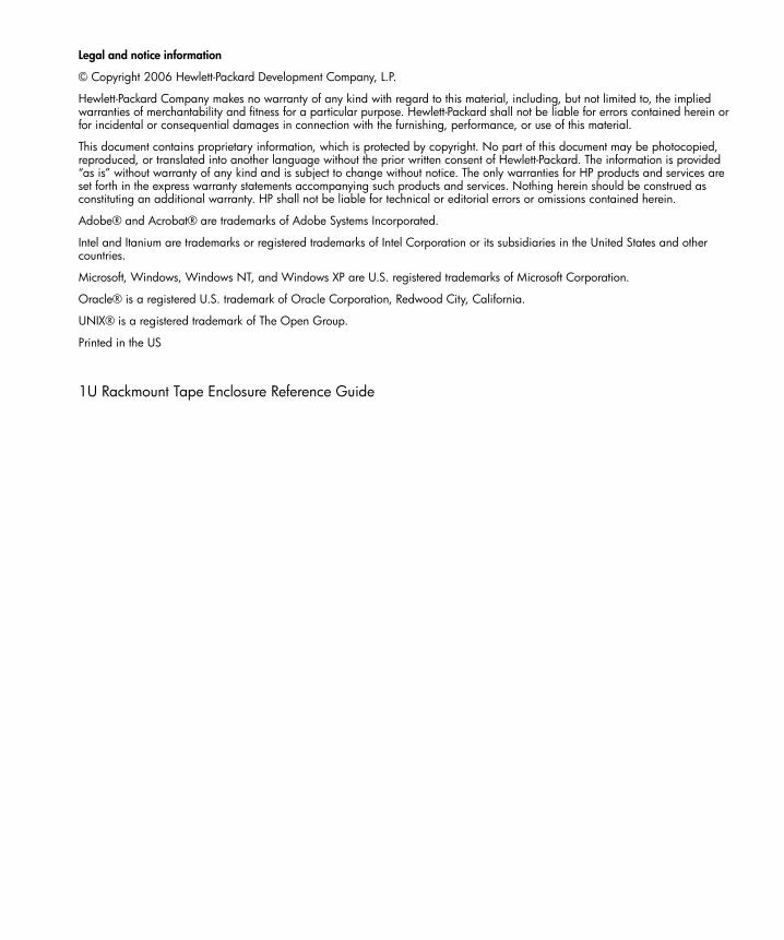
6. Attach the following cables:
Figure 10 Attach cables to the drive
NOTE: Fold excess cable length and secure with the clips provided in the tape enclosure.
7. Replace the top access panel as shown.
Figure 11 Replace access panel
1 signal2 power3 SCSI ID selector switch (SCSI drives only)
15357
1 213 2 21
SCSI USB SAS
15128
3
2
1

1U Rackmount Tape Enclosure Reference Guide 17
SCSI cable configurations The 1U Tape Enclosure supports operation of two tape drives on either 1 or 2 SCSI buses. Two internal 2-port SCSI cables are installed in the enclosure, so completing the drive installations just a matter of connecting the correct SCSI port according to your configuration.
Two drives on one SCSI bus Use the configuration shown in Figure 13 when connecting both tape drives to the same SCSI bus.
Figure 12 Two drives on one SCSI bus
NOTE: When adding a second tape drive for configurations using a single SCSI bus unplug the SCSI cable from drive 1, pass the end of the cable through internal chassis openings, and plug the end port into drive 2. Then plug the middle port into drive 1. The SCSI terminator is at the end of the cable and should be behind drive 2.
NOTE: Each SCSI device on the same SCSI bus must have a unique SCSI ID. Be sure that the SCSI ID is different for each drive and that neither is set to SCSI ID 7
1 Tape drive 1 2 Tape drive 2
3 SCSI bus 1 cable; SCSI connector nearest terminator is used for drive 2, center connector is used for drive 1
4 SCSI bus 2 cable (not used)
5 SCSI ID cables, one for each tape drive
15103
1 2
5
4
3

Tape Drive Installation18
One drive per SCSI bus Use the configuration shown in Figure 14 when connecting each drive to a separate SCSI bus.
Figure 13 One drive per SCSI bus
CAUTION: To prevent possible data errors, when there is only one drive on a SCSI bus that drive must be connected to the SCSI port closest to the terminator.
CAUTION: To avoid damaging the equipment due to electrostatic discharge, be sure to review and practice the procedures in Appendix B before handling the tape drives.
1 Tape drive 1 2 Tape drive 2
3 SCSI bus 1 cable, SCSI connector nearest terminator is used for drive 1
4 SCSI bus 2 cable, SCSI connector nearest terminator is used for drive 2
5 SCSI ID cables, one for each tape drive
15105
1 2
5
4
3

1U Rackmount Tape Enclosure Reference Guide 19
3 Rack Installation
Rail mounting kitThe rack rails supplied with the 1U rackmount tape enclosure can be used to install the unit in racks that have round, square, or threaded holes in the vertical mounting bars. The rails will fit racks with 23 - 34 inches (58 - 86 cm) separation between the front and rear vertical mounting bars. The rails are identical and may be mounted on either the left or the right side.
Figure 14 Rail mounting kit components
1 Outer rack rails2 Inner component rails3 Cable support clips4 Fastners
Tools requiredIf you are installing the tape enclosure in a rack with unmarked holes in the vertical mounting bars the following items will make the rack installation easier:
• Pencil• Tape measure
If you are installing the tape enclosure in a rack with threaded holes in the vertical mounting bars you will need the following tool:
• 3/16” (5mm) flat-blade screwdriver
15121
1
2
3
4

Rack Installation20
Installing the tape enclosure in a rack
WARNING! To reduce the risk of personal injury or equipment damage, be sure that:• The rack leveling jacks are extended to the floor• The full weight of the rack rests on the leveling jacks• The stabilizing feet are attached to the rack if it is a single rack installation• The racks are coupled in multiple rack installations• Only one component is extended at a time. A rack may become unstable if more than one
component is extended for any reason.
When installing the enclosure in a rack:
• Start at the bottom of the rack, or at the top of a previously mounted component, and work upward.
• If possible, install the heaviest components at the bottom and lighter ones toward the top of the rack.
• Make sure that the rack-mounting rails are level from front to back.
Before you beginIf you are installing the tape enclosure in a rack with unmarked holes in the vertical mounting bars, identify and mark the correct mounting holes in the rack before you begin rail installation.
CAUTION: It is important to install rack components level. To ensure that the 1U tape enclosure is installed correctly it may be necessary to measure the height of the correct mounting holes in the front and rear vertical mounting bars.
Installing the component railsComponent rails are the inner portion of the rack rail system that attached to the tape enclosure.
1. Align the slotted holes on the left and right component rails with the three pins on the sides of the enclosure 1. See Figure 15.
1U Rackmount Tape Enclosure Reference Guide 21
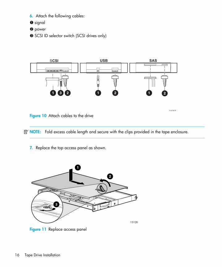
2. Slide the component rails toward the rear of the enclosure 2 until they lock into place.
Figure 15 Attaching the component rails to the enclosure
NOTE: To remove the component rail, pull out the spring-loaded tab 3 on the side of the rail and slide it forward 4.
CAUTION: If you are returning the 1U Rackmount Tape Enclosure for service, be sure to remove and save the component rails.
Installing the rack railsInstallation procedures vary depending on the rack type. The rails are shipped ready for installation in racks with round or square holes. If the rails are to be installed in racks with 10-32 threaded holes, the mounting pins must first be removed. Refer to one of the following sections for installation instructions for your rack.
• ”Installation in racks with round or square holes” on page 21• ”Installation in racks with 10-32 threaded holes” on page 24
Installation in racks with round or square holes
NOTE: The ends of the rack rails are marked FRONT and REAR for proper orientation.
15118
2
3
4 1

Rack Installation22
1. Insert the pins in front mounting plate of the outer rack rails into the previously marked holes in the front vertical mounting bars of the rack. See Figure 16. The rack rails will lock securely into place.
Figure 16 Installing the rack rails in front of rack
NOTE: To remove the rail for repositioning, push the spring-loaded tab 3 on the outside of the rack rail and slide it forward 4.
2. Extend the rack rails past the rear vertical mounting bar and insert the pins in the mounting bracket into the previously marked holes in the rack. See Figure 17. The rack rails will lock securely into place when the end of the rails are pushed forward.
Figure 17 Installing the rack rails in rear of rack
15116
FRONT
1
2
1
1
4
3
15117
FRONT
2
1
3
4
1

1U Rackmount Tape Enclosure Reference Guide 23
NOTE: To remove the rail for repositioning, push the spring-loaded tab 3 on the outside of the rack rail and slide rearward 4.
Rail installation in a rack is complete. Continue with ”Completing the installation” on page 26.

Rack Installation24
Installation in racks with 10-32 threaded holesFor installation in racks with 10-32 threaded holes in the vertical mounting bars the pins supplied on the rails must be removed. The rails will be attached with user-supplied 10-32 x.375 screws.
1. Remove the pins and threaded plates from both ends of each outer rack rail. See Figure 18. These pieces will not be used.
Figure 18 Remove the pins and mounting hardware from the rack rail
NOTE: The ends of the rack rails are marked FRONT and REAR for proper orientation.
2. Attach the front mounting plate of each outer rail to the rack using four 10-32 screws in the previously marked holes in the front vertical mounting bars of the rack. See Figure 19.
Figure 19 Installing the rack rails in front of rack
15114
1
1
1
2
15119
1U Rackmount Tape Enclosure Reference Guide 25
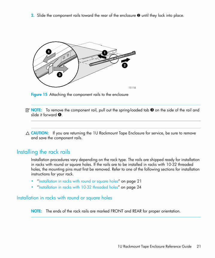
3. Extend the rack rails past the rear vertical mounting bars and attach the back mounting plate of each outer rail to the rack using four 10-32 screws in the previously marked holes. See Figure 20.
Figure 20 Installing the rack rails in rear of rack
Rail installation is complete. Continue with Completing the installation, page 26.
2
1
1
15120

Rack Installation26
Completing the installation1. Extend the stabilizing feet if provided on your rack.2. Extend the left and right rack rails from the front of the rack.3. Align the rear of the component rails on the tape enclosure with the front ends of the rack rails,
then slide the unit fully into the rack. See Figure 21.
Figure 21 Slide 1U tape enclosure into rack
CAUTION: Be sure to keep the enclosure parallel to the floor when sliding the component rails into the rack rails. Tilting the enclosure up or down could damage the rails.
NOTE: To remove the enclosure from the rack, disconnect the cables from the back of the unit. Press the latches on each side 3 and pull the enclosure from the rack 4. See Figure 21 for the location of the latches.
4. Tighten the front panel thumbscrews.5. If used, retract the stabilizing feet of the rack.6. Plug the USB cable from the server into the USB connector(s) on the rear panel of the enclosure.
See Figure 22.
15111
FRONT
3
1
2
4

1U Rackmount Tape Enclosure Reference Guide 27
7. Plug the AC power cord into the power cord connector, then into a grounded outlet. See Figure 22.
Figure 22 Connecting the power and USB cables to the tape enclosure
8. Install the cable support clip(s) at the back of the rack rail(s) on one or both sides of the enclosure. See Figure 23.
Figure 23 Install the cable support clips
9. Turn on the power to the tape enclosure with the front panel power button.
15309
15308

Rack Installation28

1U Rackmount Tape Enclosure Reference Guide 29
A Regulatory Compliance Notices
Federal Communications Commission NoticePart 15 of the Federal Communications Commission (FCC) Rules and Regulations has established Radio Frequency (RF) emission limits to provide an interference-free radio frequency spectrum. Many electronic devices, including computers, generate RF energy incidental to their intended function and are, therefore, covered by these rules. These rules place computers and related peripheral devices into two classes, A and B, depending upon their intended installation. Class A devices are those that may reasonably be expected to be installed in a business or commercial environment. Class B devices are those that may reasonably be expected to be installed in a residential environment (for example, personal computers). The FCC requires devices in both classes to bear a label indicating the interference potential of the device as well as additional operating instructions for the user.
The rating label on the device shows which class (A or B) the equipment falls into. Class B devices have an FCC logo or FCC ID on the label. Class A devices do not have an FCC logo or FCC ID on the label. Once the class of the device is determined, refer to the following corresponding statement.
Class A EquipmentThis equipment has been tested and found to comply with the limits for a Class A digital device, pursuant to Part 15 of the FCC Rules. These limits are designed to provide reasonable protection against harmful interference when the equipment is operated in a commercial environment. This equipment generates, uses, and can radiate radio frequency energy and, if not installed and used in accordance with the instructions, may cause harmful interference to radio communications. Operation of this equipment in a residential area is likely to cause harmful interference, in which case the user will be required to correct the interference at personal expense.
Class B EquipmentThis equipment has been tested and found to comply with the limits for a Class B digital device, pursuant to Part 15 of the FCC Rules. These limits are designed to provide reasonable protection against harmful interference in a residential installation. This equipment generates, uses, and can radiate radio frequency energy and, if not installed and used in accordance with the instructions, may cause harmful interference to radio communications. However, there is no guarantee that interference will not occur in a particular installation. If this equipment does cause harmful interference to radio or television reception, which can be determined by turning the equipment off and on, the user is encouraged to try to correct the interference by one or more of the following measures:
• Reorient or relocate the receiving antenna.• Increase the separation between the equipment and receiver.• Connect the equipment into an outlet on a circuit different from that to which the receiver is
connected.• Consult the dealer or an experienced radio or television technician for help.

Regulatory Compliance Notices30
ModificationsThe FCC requires the user to be notified that any changes or modifications made to this device that are not expressly approved by Hewlett-Packard Company may void the user's authority to operate the equipment.
CablesConnections to this device must be made with shielded cables with metallic RFI/EMI connector hoods in order to maintain compliance with FCC Rules and Regulations.
Declaration of Conformity for products marked with the FCC logo - United States only
This device complies with Part 15 of the FCC Rules. Operation is subject to the following two conditions: (1) this device may not cause harmful interference, and (2) this device must accept any interference received, including interference that may cause undesired operation.
For questions regarding your product, contact:
Hewlett-Packard CompanyP. O. Box 692000, Mail Stop 530113Houston, Texas 77269-2000
Or, call
1-800- 652-6672
For questions regarding this FCC declaration, contact:
Hewlett-Packard CompanyP. O. Box 692000, Mail Stop 510101Houston, Texas 77269-2000
Or, call
(281) 514-3333
To identify this product, refer to the part, series, or model number found on the product.
Canadian notice (Avis Canadien)Class A equipment
This Class A digital apparatus meets all requirements of the Canadian Interference-Causing Equipment Regulations.
Cet appareil numérique de la classe A respecte toutes les exigences du Règlement sur le matériel brouilleur du Canada.
Class B equipmentThis Class B digital apparatus meets all requirements of the Canadian Interference-Causing Equipment Regulations.

1U Rackmount Tape Enclosure Reference Guide 31
Cet appareil numérique de la classe B respecte toutes les exigences du Règlement sur le matériel brouilleur du Canada.
European Union notice
Products bearing the CE marking comply with the EMC Directive (89/336/EEC) and the Low Voltage Directive (73/23/EEC) issued by the Commission of the European Community and if this product has telecommunication functionality, the R&TTE Directive (1999/5/EC).
Compliance with these directives implies conformity to the following European Norms (in parentheses are the equivalent international standards and regulations):
• EN 55022 (CISPR 22) - Electromagnetic Interference • EN55024 (IEC61000-4-2, 3, 4, 5, 6, 8, 11) - Electromagnetic Immunity• EN61000-3-2 (IEC61000-3-2) - Power Line Harmonics• EN61000-3-3 (IEC61000-3-3) - Power Line Flicker• EN 60950 (IEC 60950) - Product Safety
BSMI notice
Regulatory Compliance Notices32
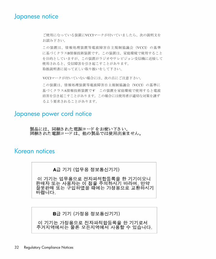
Japanese notice
Japanese power cord notice
Korean notices

1U Rackmount Tape Enclosure Reference Guide 33
Disposal of Waste Equipment by Users in Private Household in the European Union
Czechoslovakian notice
Danish notice
Dutch notice
Bortskaffelse af affald fra husstande i den Europæiske Union
Hvis produktet eller dets emballage er forsynet med dette symbol, angiver det,at produktet ikke må bortskaffes med andet almindeligt husholdningsaffald. I stedet er det dit ansvar at bortskaffe kasseret udstyr ved at aflevere det på den kommunale genbrugsstation, der forestår genvinding af kasseret elektrisk og elektronisk udstyr. Den centrale modtagelse og genvinding af kasseret udstyr i forbindelse med bortskaffelsen bidrager til bevarelse af naturlige ressourcer
og sikrer, at udstyret genvindes på en måde, der beskytter både mennesker og miljø. Yderligere oplysninger om, hvor du kan aflevere kasseret udstyr til genvinding, kan du få hos kommunen, den lokale genbrugsstation eller i den butik, hvor du købte produktet.
Verwijdering van afgedankte apparatuur door privé-gebruikers in de Europese Unie
Dit symbool op het product of de verpakking geeft aan dat dit product niet mag worden gedeponeerd bij het normale huishoudelijke afval. U bent zelf verantwoordelijk voor het inleveren van uw afgedankte apparatuur bij een inzamelingspunt voor het recyclen van oude elektrische en elektronische apparatuur. Door uw oude apparatuur apart aan te bieden en te recyclen, kunnen natuurlijke bronnen worden behouden en kan het materiaal worden
hergebruikt op een manier waarmee de volksgezondheid en het milieu worden beschermd. Neem contact op met uw gemeente, het afvalinzamelingsbedrijf of de winkel waar u het product hebt gekocht voor meer informatie over inzamelingspunten waar u oude apparatuur kunt aanbieden voor recycling.

Regulatory Compliance Notices34
English notice
Estonian notice
Finnish notice
Disposal of waste equipment by users in private household in the European Union
This symbol on the product or on its packaging indicates that this product must not be disposed of with your other household waste. Instead, it is your responsibility to dispose of your waste equipment by handing it over to a designated collection point for recycling of waste electrical and electronic equipment. The separate collection and recycling of your waste equipment at the time of disposal will help to conserve natural resources and ensure that it is recycled in a manner that protects human health
and the environment. For more information about where you can drop off your waste equipment for recycling, please contact your local city office, your household waste disposal service, or the shop where you purchased the product.
Laitteiden hävittäminen kotitalouksissa Euroopan unionin alueella
Jos tuotteessa tai sen pakkauksessa on tämä merkki, tuotetta ei saa hävittää kotitalousjätteiden mukana. Tällöin hävitettävä laite on toimitettava sähkölaitteiden ja elektronisten laitteiden kierrätyspisteeseen. Hävitettävien laitteiden erillinen käsittely ja kierrätys auttavat säästämään luonnonvaroja ja varmistamaan, että laite kierrätetään tavalla, joka estää terveyshaitat ja suojelee luontoa. Lisätietoja paikoista, joihin hävitettävät laitteet voi toimittaa kierrätettäväksi, saa ottamalla
yhteyttä jätehuoltoon tai liikkeeseen, josta tuote on ostettu.
1U Rackmount Tape Enclosure Reference Guide 35
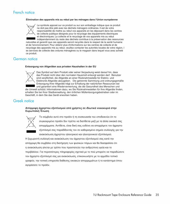
French notice
German notice
Greek notice
Élimination des appareils mis au rebut par les ménages dans l'Union européenne
Le symbole apposé sur ce produit ou sur son emballage indique que ce produit ne doit pas être jeté avec les déchets ménagers ordinaires. Il est de votre responsabilité de mettre au rebut vos appareils en les déposant dans les centres de collecte publique désignés pour le recyclage des équipements électriques et électroniques. La collecte et le recyclage de vos appareils mis au rebut indépendamment du reste des déchets contribue à la préservation des ressources
naturelles et garantit que ces appareils seront recyclés dans le respect de la santé humaine et de l'environnement. Pour obtenir plus d'informations sur les centres de collecte et de recyclage des appareils mis au rebut, veuillez contacter les autorités locales de votre région, les services de collecte des ordures ménagères ou le magasin dans lequel vous avez acheté ce produit.
Entsorgung von Altgeräten aus privaten Haushalten in der EU
Das Symbol auf dem Produkt oder seiner Verpackung weist darauf hin, dass das Produkt nicht über den normalen Hausmüll entsorgt werden darf. Benutzer sind verpflichtet, die Altgeräte an einer Rücknahmestelle für Elektro- und Elektronik-Altgeräte abzugeben. Die getrennte Sammlung und ordnungsgemäße Entsorgung Ihrer Altgeräte trägt zur Erhaltung der natürlichen Ressourcen bei und garantiert eine Wiederverwertung, die die Gesundheit des Menschen und
die Umwelt schützt. Informationen dazu, wo Sie Rücknahmestellen für Ihre Altgeräte finden, erhalten Sie bei Ihrer Stadtverwaltung, den örtlichen Müllentsorgungsbetrieben oder im Geschäft, in dem Sie das Gerät erworben haben.

Regulatory Compliance Notices36
Hungarian notice
Italian notice
Latvian notice
Smaltimento delle apparecchiature da parte di privati nel territorio dell'Unione Europea
Questo simbolo presente sul prodotto o sulla sua confezione indica che il prodotto non può essere smaltito insieme ai rifiuti domestici. È responsabilità dell'utente smaltire le apparecchiature consegnandole presso un punto di raccolta designato al riciclo e allo smaltimento di apparecchiature elettriche ed elettroniche. La raccolta differenziata e il corretto riciclo delle apparecchiature da smaltire permette di proteggere la salute degli individui e l'ecosistema. Per ulteriori informazioni relative
ai punti di raccolta delle apparecchiature, contattare l'ente locale per lo smaltimento dei rifiuti, oppure il negozio presso il quale è stato acquistato il prodotto.

1U Rackmount Tape Enclosure Reference Guide 37
Lihuanian notice
Polish notice
Portuguese notice
Descarte de Lixo Elétrico na Comunidade Européia
Este símbolo encontrado no produto ou na embalagem indica que o produto não deve ser descartado no lixo doméstico comum. É responsabilidade do cliente descartar o material usado (lixo elétrico), encaminhando-o para um ponto de coleta para reciclagem. A coleta e a reciclagem seletivas desse tipo de lixo ajudarão a conservar as reservas naturais; sendo assim, a reciclagem será feita de uma forma segura, protegendo o ambiente e a saúde das pessoas. Para obter
mais informações sobre locais que reciclam esse tipo de material, entre em contato com o escritório da HP em sua cidade, com o serviço de coleta de lixo ou com a loja em que o produto foi adquirido.

Regulatory Compliance Notices38
Slovakian notice
Slovenian notice
Spanish notice
Swedish notice
Eliminación de residuos de equipos eléctricos y electrónicos por parte de usuarios particulares en la Unión Europea
Este símbolo en el producto o en su envase indica que no debe eliminarse junto con los desperdicios generales de la casa. Es responsabilidad del usuario eliminar los residuos de este tipo depositándolos en un "punto limpio" para el reciclado de residuos eléctricos y electrónicos. La recogida y el reciclado selectivos de los residuos de aparatos eléctricos en el momento de su eliminación contribuirá a conservar los recursos naturales y a garantizar el reciclado de estos residuos
de forma que se proteja el medio ambiente y la salud. Para obtener más información sobre los puntos de recogida de residuos eléctricos y electrónicos para reciclado, póngase en contacto con su ayuntamiento, con el servicio de eliminación de residuos domésticos o con el establecimiento en el que adquirió el producto.
Bortskaffande av avfallsprodukter från användare i privathushåll inom Europeiska Unionen
Om den här symbolen visas på produkten eller förpackningen betyder det att produkten inte får slängas på samma ställe som hushållssopor. I stället är det ditt ansvar att bortskaffa avfallet genom att överlämna det till ett uppsamlingsställe avsett för återvinning av avfall från elektriska och elektroniska produkter. Separat insamling och återvinning av avfallet hjälper till att spara på våra naturresurser och gör att avfallet återvinns på ett sätt som skyddar människors hälsa och miljön.
Kontakta ditt lokala kommunkontor, din närmsta återvinningsstation för hushållsavfall eller affären där du köpte produkten för att få mer information om var du kan lämna ditt avfall för återvinning.

1U Rackmount Tape Enclosure Reference Guide 39

Regulatory Compliance Notices40

1U Rackmount Tape Enclosure Reference Guide 41
B Electrostatic DischargeTo prevent damage to the system, be aware of the precautions you need to follow when setting up the system or handling parts. A discharge of static electricity from a finger or other conductor may damage system boards or other static-sensitive devices. This type of damage may reduce the life expectancy of the device.
To prevent electrostatic damage, observe the following precautions:
• Avoid hand contact by transporting and storing products in static-safe containers.• Keep electrostatic-sensitive parts in their containers until they arrive at static-free workstations.• Place parts on a grounded surface before removing them from their containers.• Avoid touching pins, leads, or circuitry.• Always be properly grounded when touching a static-sensitive component or assembly.
Grounding methodsThere are several methods for grounding. Use one or more of the following methods when handling or installing electrostatic-sensitive parts:
• Use a wrist strap connected by a ground cord to a grounded workstation or computer chassis. Wrist straps are flexible straps with a minimum of 1 megohm ± 10 percent resistance in the ground cords. To provide proper grounding, wear the strap snug against the skin.
• Use heel straps, toe straps, or boot straps at standing workstations. Wear the straps on both feet when standing on conductive floors or dissipating floor mats.
• Use conductive field service tools. • Use a portable field service kit with a folding static-dissipating work mat.
If you do not have any of the suggested equipment for proper grounding, have an authorized reseller install the part.
NOTE: For more information on static electricity, or for assistance with product installation, contact your authorized reseller.

Electrostatic Discharge42

1U Rackmount Tape Enclosure Reference Guide 43
C Specifications
Table 2 HP StorageWorkds 1U Rackmount Tape Enclosure
Parameter English MetricDimensions
HeightDepthWidth
1.75 in25.25 in19.0 in
4.44 cm64.1 cm48.3 cm
Weight (1 drive installed) 20 lb 9.07 kgInput power requirements
Rated input voltageRated input currentRated input frequencyInput power (max)
90 to 264 VAC2.4 A47 - 63 Hz140 W*
90 to 264 VAC2.4 A47 - 63 Hz140 W*
Heat Dissipation (max) 478 BTU/hr* 478 BTU/hr*Temperature range
OperatingNon-operating
41° to 104° F-40° to 158° F
5° to 40° C-40° to 70° C
Relative humidityOperating (non-condensing)Non-operating
20% to 80%5% to 95%
20% to 80%5% to 95%
Wet bulb temperature (max) 79° F 26° CAltitude (max)
OperatingNon-operating
0 to 15,000 ft0 to 50,000 ft
0 to 4600 m0 to 15200 m
* Input power and Heat dissipation specifications are maximum values and apply to worst-case conditions at full rated power supply load. The power/heat dissipation for your installation will vary depending on the equipment configuration.

Specifications44

1U Rackmount Tape Enclosure Reference Guide 45
Index
Aaudience 5authorized reseller, HP 7
Ccapacity 9compatibility 9conventions
document 5text symbols 6
Ddisposal
waste equipment for EU private households 34document
conventions 5prerequisites 5related documentation 5
Eelectrostatic discharge 41, 43enclosure
front view 9installing into the rack 20standard features 9
European Union Notice 31
Ffeatures 9front panel components 10
Hhelp, obtaining 6, 7HP
authorized reseller 7storage web site 7Subscriber’s choice web site 7technical support 6
Iinternal components 11
Pprerequisites 5
Rrack stability, warning 6rear panel components 10regulatory compliance notices 29related documentation 5
SSubscriber’s choice, HP 7symbols in text 6
Ttechnical support, HP 6text symbols 6
Wwarning
rack stability 6waste equipment disposal for EU private households
34web sites
HP storage 7HP Subscriber’s choice 7

46