HP ProCurve Wireless 170wl Radio Card External Antenna
14
HP ProCurve Wireless 170wl Radio Card External Antenna User’s Guide
Transcript of HP ProCurve Wireless 170wl Radio Card External Antenna

HP ProCurve Wireless 170wl Radio Card External Antenna
User’s Guide

Hewlett-Packard Company8000 Foothills Boulevard, m/s 5552Roseville, California 95747-5552http://www.hp.com/go/hpprocurve
© Copyright 2004 Hewlett-Packard Development Company,L.P. The information contained herein is subject to change without notice.
This document contains proprietary information, which is protected by copyright. No part of this document may be photocopied, reproduced, or translated into another language without the prior written consent of Hewlett-Packard.
Publication Number
5990-6069May 2004
Applicable Products
HP ProCurve 5 dBi indoor/outdoor omnidirctional antenna (J8441A)HP ProCurve 7 dBi indoor/outdoor directional antenna (J8443A)HP ProCurve 8 dBi outdoor omnidirctional antenna (J8444A)HP ProCurve 11 dBi indoor/outdoor wide angle directional antenna (J8446A)HP ProCurve MC-Card to R-SMA cable (J8447A)HP ProCurve 14 dBi yagi antenna (J8448A)HP ProCurve Wireless AP 520wl (J8133A)HP ProCurve 802.11g 170wl Card (J8430A)HP ProCurve 802.11g 170wl Card (J8431A)HP ProCurve 802.11g 170wl Card (J8432A)
Disclaimer
HEWLETT-PACKARD COMPANY MAKES NO WARRANTY OF ANY KIND WITH REGARD TO THIS MATERIAL, INCLUDING, BUT NOT LIMITED TO, THE IMPLIED WARRANTIES OF MERCHANTABILITY AND FITNESS FOR A PARTICULAR PURPOSE. Hewlett-Packard shall not be liable for errors contained herein or for incidental or consequential damages in connection with the furnishing, performance, or use of this material.
The only warranties for HP products and services are set forth in the express warranty statements accompanying such products and services. Nothing herein should be construed as constituting an additional warranty. HP shall not be liable for technical or editorial errors or omissions contained herein.
Hewlett-Packard assumes no responsibility for the use or reliability of its software on equipment that is not furnished by Hewlett-Packard.
Warranty
See the Customer Support/Warranty booklet included with the product.
A copy of the specific warranty terms applicable to your Hewlett-Packard products and replacement parts can be obtained from your HP Sales and Service Office or authorized dealer.

Using an External Antenna with the 170wl Radio Card
HP provides a variety of external antenna options for extending the radio range and shaping the coverge area of your access point by connecting antennas to your HP ProCurve 802.11g 170wl radio card . These antennas offer a number of different mounting locations, including indoor or outdoor, wall, ceiling, or radio mast.
This guide shows you how to install an external antenna for your 170wl radio card.
P r o f e s s i o n a l I n s t a l l a t i o n R e q u i r e d
Only the HP antennas listed in this guide are permitted to be connected to the 170wl radio card. You must use the appropriate antennas, cables, and where applicable, surge arrestors, for your given region. You are responsible for verifying local regulations or legislation that may impose restrictions on the use of specific antenna and cable combinations. For this reason, HP recom-mends that you consult with a professional installer who is trained in RF installation and knowledgeable in the local regulations prior to connecting an external antenna to your wireless radio product. It is the responsibility of the end user to ensure the antenna installation complies with the local radio regulations.
1

Using an External Antenna with the 170wl Radio CardExternal Antenna Options
External Antenna OptionsThe 170wl radio card external antenna options are outlined in the following table:
Table 1. Summary of External Antennas to Use With the 170wl radio card
Antenna Type Part Number Mounting Horizontal Beamwidth (3dB)
Vertical Beamwidth (3dB)
5 dBi indoor/outdoor omnidirectional
J8441A Ceiling or mast 360 Degrees 31 Degrees
7 dBi indoor/outdoor directional J8443A Flush wall mount withintegrated articulating feature
65 Degrees 50 Degrees
8 dBi outdoor omnidirectional J8444A* Mast 360 Degrees 12 Degrees
11 dBi indoor/outdoor wideangle directional
J8446A* Flush wall mount, tilt mount for mast
120 Degrees 13 Degrees
MC-Card to R-SMA cableThiscable must be used with all the above antennas
J8447A n/a n/a n/a
14 dBi yagiComes with it’s own adapter cable
J8448A* Articulating wall or mast
34 Degrees 30 Degrees
* These antennas are not permitted for use in North America.
2

Using an External Antenna with the 170wl Radio CardPre-Installation Considerations
Pre-Installation Considerations
Planning the Installation
To determine the best location of your wireless access points and antennas, we recommend conducting a site survey before placing the devices in their final locations. For information on how to conduct a site survey, contact your local reseller.
W A R N I N G Never install an antenna or construct a radio mast near overhead
powerlines.
C a u t i o n Never mount the access point outdoors to be near an external antenna. The access point must always be installed indoors.
■ Installation Location - Plan the antenna’s position and orientation. Consider these points:
• Use the antenna’s mounting bracket or other hardware, if included.
• For optimum performance, mount antennas as high as possible above any obstructions, and away from any signal absorbing or reflecting structures (such as those containing metal).
• Be sure there are no other radio antennas mounted within 2 m (6 ft).
• Consider the antenna’s radio coverage pattern so that it can properly cover the intended service area and not interfere with other radios and antennas.
• Because most antenna pigtail cables are a relatively short length, be sure to find a suitable mounting position for the antenna that is not too far from the access point. Alternatively, you may need to relocate the access point to achieve the desired coverage area for the antenna. Use an extension cable to span excessive distance between the antenna and the access point.
■ Omnidirectional Antennas - Consider these factors when selecting a location for these antennas:
• Always mount the antenna in a vertical orientation so that the radio coverage pattern fills the intended horizontal space.
3

Using an External Antenna with the 170wl Radio CardPre-Installation Considerations
• For optimum coverage, mount the antenna at the center of the area with a line-of-sight path to all points within the area.
• Avoid mounting next to or near building support columns or other obstructions that may cause reduced signal or null zones in parts of the coverage area.
• When mounting outdoors using a mast, make sure the antenna extends beyond the top of the mast.
■ Directional Antennas - Consider these factors when selecting a location for these antennas:
• For optimum coverage, mount the antenna above any obstructions, directed at the center of the coverage area sector.
• High-gain directional antennas provide a flattened radio coverage pattern in the horizontal plane. Use the tilting or articulated mounts to point the antennas towards the coverage area.
■ Outdoor Installation - When installing an antenna outdoors, be sure to consider these additional factors:
• Always place the antenna away from power and telephone lines.
• Ensure the antenna, any supporting structure, and cables are all properly grounded.
• For lightning protection, it is highly recommended to use a lightning arrestor immediately before the cable enters the building.
4

Using an External Antenna with the 170wl Radio CardInstallation Procedure
Installation Procedure
1. Mount the Antenna
Install the antenna in its planned location using the mounting hardware included with the antenna.
Refer to documentation included with the antenna for specific information and installation instructions.
2. Connect to the Radio Card
1. Disable the access point radio using the web browser interface, CLI, or SNMP.
2. Remove power to the access point.
3. Connect the antenna pigtail cable to one of the following:
• Adapter cable. This cable connects the antenna pigtail cable to the radio card.
• Appropriate extension cable. This cable connects to the antenna pigtail cable, for an extension of length and/or for a required insertion loss (table 2), then the extension cable connects to the adapter cable, which connects to the radio card. Insertion loss is made up of added cable, connectors, and lightening arrestors.
Radio Card
Adapter Cable
Atenna Pigtail
Access Point 520wl
5

Using an External Antenna with the 170wl Radio CardInstallation Procedure
6
4. Remove the rubber tab from the end of the radio card.
5. Connect the adapter cable to the radio card.
6. Reconnect power to the access point.
N o t e Before enabling the radio with an external antenna attached, be sure to first configure the access point’s antenna mode and transmit power settings.
Adapter Cable
Radio Card
Extension Cable(Variable Length)
Antenna Pigtail
Access Point 520wl

Using an External Antenna with the 170wl Radio CardInstallation Procedure
3. Configure the Radio Transmit Power Control Levels
The access point must be configured for the type of radio card and transmit (TX) power must be limited to conform to local regulations. Use the regional settings for each antenna as provided in the TX Power Control table below. For more information on access point configuration, refer to "Configuring the AP using CLI Commands" section, of Appendix C, of the HP ProCurve Wireless
Access Point 520wl User’s Guide, which is on the Documentation CD-ROM that came with your access point.
C a u t i o n An improper combination of transmit power and antenna gain may result in an EIRP (equivalent isotropically radiated power) power level in excess of the legally imposed limit. The transmit power reduction required for each antenna is listed in the following table. Failure to adhere to these guidelines may violate the radio laws for your region. For additional information on setting radio transmit power, refer to "Configuring the AP using CLI Commands" section, of Appendix C, of the HP ProCurve Wireless Access Point 520wl User’s Guide.
Table 2. TX Power Control Setting and Required Insertin Loss.
Antenna TypeEuropean Union
Power Level Setting (%) Required Insertion Loss (dB)
5 dBi Indoor/Outdoor Omni, J8441A 100%50%
0.7none
7 dBi Indoor/Outdoor Directional, J8443A 100%50%
3none
8 dBi Outdoor Omni, J8444A 100%50%
3.70.7
11 dBi Indoor/Outdoor wide angle directional, J8446A
100%50%
6.73.7
14 dBi yagi, J8448A 100%50%
10.17.1
7

Using an External Antenna with the 170wl Radio CardInstallation Procedure
TX Power Control Limits
N o t e TX Power Control is only supported on the HP ProCurve Wireless 802.11g AP Card 170wl. Do not use the 12.5% and 25% options. Although you can select them, they are not valid for the 170wl.
The TX Power Control feature lets the user configure the transmit power level of the radio card in the access point at one of four levels:
■ 100% of the maximum transmit power level of the radio card.
■ 50%
■ 25%
■ 12.5 %
Configuring TX Power Limits Using the Web Inteface
1. Open the Web browser on a network computer.
N o t e The HTTP interface supports the following Web brouser:
• Microsoft Internet Explorer 6 with Service Pack 1 or later
• Netscape 6.1 or later
2. If necessary, disable the Internet proxy settings. For Internet Explorer users, follow these steps:
• Select Tools > Internet Options....
• Click the Connections tab.
• Click LAN Settings....
• If necessary, remove the check mark from the Use a proxy server box.
• Click OK twice to save your changes and return to Internet Explorer.
3. Enter the Access Point’s IP address in the browser’s Address field and press Enter. The Enter Network Password screen appears.
4. Enter the HTTP password in the Password field and click OK. Leave the User Name field blank. (By default, the HTTP password is "public"). The System Status screen appears.
8

Using an External Antenna with the 170wl Radio CardInstallation Procedure
5. Click the Configure button located on the left side of the screen.
6. Click the tab that corresponds to the parameter you want to configure. For this procedure, click Interfaces.
9
Using an External Antenna with the 170wl Radio CardInstallation Procedure
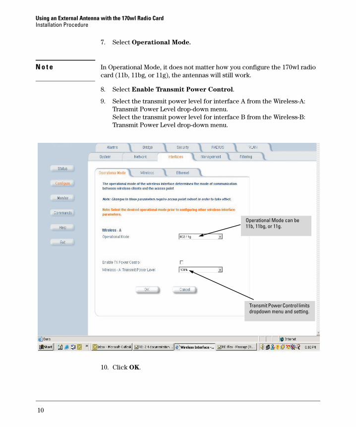
7. Select Operational Mode.
N o t e In Operational Mode, it does not matter how you configure the 170wl radio card (11b, 11bg, or 11g), the antennas will still work.
8. Select Enable Transmit Power Control.
9. Select the transmit power level for interface A from the Wireless-A: Transmit Power Level drop-down menu. Select the transmit power level for interface B from the Wireless-B: Transmit Power Level drop-down menu.
10. Click OK.
g
Operational Mode can be 11b, 11bg, or 11g.
Transmit Power Control limits dropdown menu and setting.
10

Using an External Antenna with the 170wl Radio CardInstallation Procedure
11. Reboot the Access Point for the changes to take effect.
Configuring TX Power Limits Using the CLI
Use the Show and Set commands in the CLI to configure the AP. Refer to "Configuring the AP using CLI Commands" section, of Appendix C, of the "HP
ProCurve Wireless Access Point 520wl User’s Guide," for complete descrip-tions of these commands.
11

Technical information in this document is subject to change without notice.
Copyright Hewlett-Packard Company, 2004. All rights reserved. Reproduction, adaptation, or translation without prior written permission is prohibited except as allowed under the copyright laws.
Product of SingaporeMay 2004
Manual Part Number5990-6069
*5990-6069*