
HP iLO 4 User Guide - lost- home page · PDF...
289
HP iLO 4 User Guide Abstract The HP iLO 4 firmware provides ways to configure, update, and operate HP ProLiant Gen8 servers remotely. This guide describes these features and how to use them with the iLO web interface and iLO RBSU. This guide discusses HP iLO for HP ProLiant servers and HP ProLiant BladeSystem server blades. For information about iLO for Integrity servers and server blades, see the HP website at h t tp://w w w .hp .co m/go/in t egr it y iL O . HP Part Number: 684918-005 Published: September 2013 Edition: 1
Transcript of HP iLO 4 User Guide - lost- home page · PDF...
HP iLO 4 User Guide
AbstractThe HP iLO 4 firmware provides ways to configure, update, and operate HP ProLiant Gen8 servers remotely. This guide describesthese features and how to use them with the iLO web interface and iLO RBSU.
This guide discusses HP iLO for HP ProLiant servers and HP ProLiant BladeSystem server blades. For information about iLO forIntegrity servers and server blades, see the HP website at http://www.hp.com/go/integrityiLO.
HP Part Number: 684918-005Published: September 2013Edition: 1

© Copyright 2011, 2013 Hewlett-Packard Development Company, L.P
Confidential computer software. Valid license from HP required for possession, use or copying. Consistent with FAR 12.211 and 12.212, CommercialComputer Software, Computer Software Documentation, and Technical Data for Commercial Items are licensed to the U.S. Government undervendor's standard commercial license.
The information contained herein is subject to change without notice. The only warranties for HP products and services are set forth in the expresswarranty statements accompanying such products and services. Nothing herein should be construed as constituting an additional warranty. HP shallnot be liable for technical or editorial errors or omissions contained herein.
Acknowledgements
Microsoft®, Windows®, Windows NT® , and Windows Vista® are U.S. registered trademarks of Microsoft Corporation.
Intel is a trademark of Intel Corporation in the U.S. and other countries.
Java is a registered trademark of Oracle and/or its affiliates.
Contents1 Introduction to iLO....................................................................................13
HP iLO features......................................................................................................................13iLO web interface...................................................................................................................14iLO RBSU...............................................................................................................................14iLO Mobile application............................................................................................................14iLO scripting and command line...............................................................................................15
2 Setting up iLO..........................................................................................16Preparing to set up iLO............................................................................................................16Connecting iLO to the network.................................................................................................18Setting up iLO by using iLO RBSU.............................................................................................18
Configuring the network settings (static IP addresses only).......................................................19Setting up iLO user accounts by using iLO RBSU.....................................................................20
Setting up iLO by using the iLO web interface............................................................................21Logging in to iLO for the first time.............................................................................................21Activating iLO licensed features................................................................................................22Installing the iLO drivers...........................................................................................................22
Microsoft device driver support............................................................................................23Linux device driver support..................................................................................................23VMware device driver support.............................................................................................24
3 Configuring iLO.......................................................................................25Updating firmware..................................................................................................................25
Updating firmware by using an online method.......................................................................25Performing an in-band firmware update............................................................................25Performing an out-of-band firmware update.......................................................................26
Updating firmware by using an offline method.......................................................................26Obtaining the iLO firmware image file..................................................................................26Obtaining supported server firmware image files...................................................................27Updating firmware by using a browser.................................................................................27
Using language packs............................................................................................................28Installing a language pack..................................................................................................29Selecting a language pack.................................................................................................30Configuring the default language settings..............................................................................31Configuring the current language settings..............................................................................31Uninstalling a language pack..............................................................................................31
iLO licensing..........................................................................................................................32Free iLO 60-day evaluation license.......................................................................................32Installing an iLO license by using a browser..........................................................................33
Administering users.................................................................................................................33Viewing local users............................................................................................................34Viewing directory groups....................................................................................................35Adding or editing local users..............................................................................................35
IPMI/DCMI users..........................................................................................................37Administering directory groups............................................................................................37Deleting a user or a directory group.....................................................................................39
Configuring iLO access settings................................................................................................39Configuring service settings.................................................................................................39Configuring IPMI/DCMI settings..........................................................................................41Configuring access options.................................................................................................41
Configuring access options by using the iLO web interface.................................................41Configuring iLO access options by using iLO RBSU............................................................43
Contents 3

Configuring global settings by using iLO RBSU.............................................................44Configuring serial CLI options by using iLO RBSU.........................................................44
Logging in to iLO by using an SSH client...............................................................................45Configuring iLO security..........................................................................................................46
General security guidelines.................................................................................................46Passwords....................................................................................................................46iLO RBSU security..........................................................................................................47iLO Security Override Switch administration......................................................................48
TPM support......................................................................................................................49User accounts and access...................................................................................................49
User privileges..............................................................................................................49Login security................................................................................................................49
Administering SSH keys......................................................................................................50About SSH keys............................................................................................................50Authorizing a new key by using the iLO web interface.......................................................51Authorizing a new key by using the CLI............................................................................52Deleting keys................................................................................................................52Authorizing keys from an HP SIM server...........................................................................52
Administering SSL certificates..............................................................................................52Viewing certificate information........................................................................................53Obtaining and importing a certificate..............................................................................53
Configuring directory settings..............................................................................................55Configuring authentication and directory server settings.....................................................56Running directory tests...................................................................................................58
Viewing directory test results......................................................................................60Using the directory test controls .................................................................................62
Using encryption................................................................................................................62Viewing encryption enforcement settings...........................................................................63Modifying the AES/DES encryption setting.......................................................................64
Connecting to iLO by using AES or 3DES encryption.....................................................64Enabling FIPS Mode......................................................................................................64Disabling FIPS Mode.....................................................................................................65
Configuring iLO for HP SSO................................................................................................65Configuring iLO for HP SSO...........................................................................................66Adding trusted certificates..............................................................................................67
Extracting the HP SIM server certificate........................................................................68Viewing trusted certificates.............................................................................................68Removing trusted certificates...........................................................................................69
Configuring Remote Console security settings.........................................................................69Configuring Remote Console Computer Lock settings..........................................................69Configuring Integrated Remote Console Trust settings (.NET IRC)..........................................71
Configuring the Login Security Banner..................................................................................71Configuring iLO network settings..............................................................................................73
Viewing network settings.....................................................................................................73Configuring general network settings....................................................................................76
Using the iLO Shared Network Port..................................................................................78Enabling the iLO Shared Network Port feature..............................................................79Re-enabling the iLO Dedicated Network Port................................................................81
Configuring IPv4 settings....................................................................................................81Configuring IPv6 settings....................................................................................................83Configuring SNTP settings...................................................................................................86
Configuring iLO Management settings.......................................................................................87Installing AMS or the Insight Management Agents..................................................................88
Verifying the AMS installation.........................................................................................89Verifying AMS installation: Windows..........................................................................89
4 Contents
Verifying AMS installation: SUSE and Red Hat.............................................................90Verifying AMS installation: VMware............................................................................90Verifying AMS installation: Ubuntu..............................................................................90
Configuring SNMP settings.................................................................................................90Configuring SNMPv3 Users.................................................................................................92Configuring the SNMPv3 Engine ID.....................................................................................93Configuring SNMP alerts....................................................................................................93
Using the AMS Control Panel to configure SNMP and SNMP alerts (Windows only)..............94SNMP traps..................................................................................................................95
Configuring Insight Management integration.........................................................................97Configuring AlertMail settings.............................................................................................98
Enabling AlertMail........................................................................................................98Disabling AlertMail.......................................................................................................99
Configuring Remote Syslog settings......................................................................................99Enabling iLO Remote Syslog...........................................................................................99Disabling iLO Remote Syslog........................................................................................100
Configuring Remote Support..................................................................................................100Data collected by Insight Remote Support............................................................................101Prerequisites....................................................................................................................102Registering for Insight Remote Support................................................................................102Unregistering from Insight Remote Support .........................................................................104Working with Insight Remote Support service events.............................................................104
Using maintenance mode.............................................................................................104Sending a test service event..........................................................................................105Viewing the Service Event Log.......................................................................................105Clearing the Service Event Log......................................................................................106
Viewing and sending Remote Support data collection information..........................................106Sending Data Collection information..............................................................................106Sending Active Health System reporting information.........................................................107
4 Using iLO..............................................................................................109Using the iLO web interface...................................................................................................109
Browser support...............................................................................................................109Logging in to iLO.............................................................................................................109Handling an unknown authority.........................................................................................110Using the iLO controls.......................................................................................................111Starting a remote management tool....................................................................................111Language pack support....................................................................................................111
Viewing iLO overview information...........................................................................................111Viewing system information...............................................................................................111Viewing status information.................................................................................................113Viewing the active iLO sessions..........................................................................................114
Viewing iLO system information..............................................................................................114Viewing health summary information..................................................................................114Viewing fan information....................................................................................................115Viewing temperature information .......................................................................................117
Viewing the temperature graph.....................................................................................117Viewing temperature sensor data...................................................................................118
Viewing power information...............................................................................................119Viewing processor information...........................................................................................124Viewing memory information.............................................................................................125
Advanced Memory Protection.......................................................................................125Memory Summary.......................................................................................................127Memory Details..........................................................................................................127
Viewing network information.............................................................................................128
Contents 5

Viewing storage information..............................................................................................129Controllers.................................................................................................................131Drive Enclosures..........................................................................................................132Logical Drives.............................................................................................................132Physical Drives............................................................................................................132
Viewing firmware information............................................................................................132Using the iLO Event Log.........................................................................................................133
Viewing the iLO Event Log.................................................................................................133Saving the iLO Event Log...................................................................................................135Clearing the iLO Event Log................................................................................................135
Using the Integrated Management Log....................................................................................136Viewing the IML...............................................................................................................136Marking a log entry as repaired........................................................................................138Adding a maintenance note to the IML...............................................................................138Saving the IML................................................................................................................138Clearing the IML..............................................................................................................139
Using the HP Active Health System..........................................................................................139Downloading the Active Health System log for a date range..................................................139Downloading the entire Active Health System log.................................................................141Extracting the Active Health System log by using curl............................................................141Clearing the Active Health System log................................................................................142
Using iLO diagnostics............................................................................................................142Resetting iLO through the web interface..............................................................................144
Using Location Discovery Services...........................................................................................144Using the HP Insight Management Agents................................................................................146Using the Integrated Remote Console......................................................................................146
.NET IRC requirements......................................................................................................147Microsoft .NET Framework............................................................................................147Microsoft ClickOnce....................................................................................................147
Java IRC requirements......................................................................................................148Recommended client settings........................................................................................148Recommended server settings.......................................................................................149
Starting the Remote Console..............................................................................................149Acquiring the Remote Console...........................................................................................150Using the Remote Console power switch.............................................................................151Using iLO Virtual Media from the Remote Console................................................................152Using Shared Remote Console (.NET IRC only)....................................................................152Using Console Capture (.NET IRC only)..............................................................................153
Viewing Server Startup and Server Prefailure sequences...................................................153Saving Server Startup and Server Prefailure video files.....................................................154Capturing video files...................................................................................................154Viewing saved video files.............................................................................................154
Creating Remote Console hot keys.....................................................................................155Creating a hot key......................................................................................................155Resetting hot keys........................................................................................................156
Using the text-based Remote Console......................................................................................156Using the iLO Virtual Serial Port.........................................................................................157
Configuring the iLO Virtual Serial Port in the host system RBSU..........................................157Configuring the iLO Virtual Serial Port for Linux...............................................................160Configuring the iLO Virtual Serial Port for the Windows EMS Console................................161Viewing the iLO Virtual Serial Port log............................................................................161
Using the Text-based Remote Console (Textcons)..................................................................161Customizing the Text-based Remote Console...................................................................162Using the Text-based Remote Console............................................................................163Using Linux with the Text-based Remote Console..............................................................163
6 Contents

Using iLO Virtual Media........................................................................................................163Virtual Media operating system information.........................................................................165
Operating system USB requirement................................................................................165Using Virtual Media with Windows 7............................................................................165Operating system considerations: Virtual Floppy/USB key................................................165
Changing diskettes.................................................................................................165Operating system considerations: Virtual CD/DVD-ROM..................................................166
Mounting a USB Virtual Media CD/DVD-ROM on Linux systems...................................166Operating system considerations: Virtual Folder .............................................................166
Using iLO Virtual Media from the iLO web interface.............................................................167Viewing and modifying the Virtual Media port................................................................167Viewing and ejecting local media.................................................................................168Connecting scripted media...........................................................................................168Viewing and ejecting scripted media.............................................................................168
Using iLO Virtual Media from the Remote Console................................................................169Using a Virtual Floppy/USB key....................................................................................169
Using a physical floppy disk or USB key drive on a client PC........................................169Using an image file................................................................................................169Using an image file through a URL (IIS/Apache – .NET IRC only)..................................169
Using a Virtual CD/DVD-ROM......................................................................................169Using a physical CD/DVD-ROM drive on a client PC...................................................170Using an image file................................................................................................170Using an image file through a URL (IIS/Apache – .NET IRC only)..................................170
Using the Create Media Image feature (Java IRC only).....................................................170Creating an iLO disk image file................................................................................170Copying data from an image file to a physical disk....................................................171
Using a Virtual Folder (.NET IRC only)............................................................................172Setting up IIS for scripted Virtual Media..............................................................................172
Configuring IIS............................................................................................................172Configuring IIS for read/write access.............................................................................173Inserting Virtual Media with a helper application............................................................173Sample Virtual Media helper application.......................................................................174
Configuring Virtual Media Boot Order................................................................................175Changing the server boot order....................................................................................175Changing the one-time boot status................................................................................176Using the additional options.........................................................................................176
About server power..............................................................................................................176Powering on the server.....................................................................................................176Brownout recovery...........................................................................................................177Graceful shutdown...........................................................................................................177Power efficiency...............................................................................................................177
Using iLO Power Management...............................................................................................177Managing the server power..............................................................................................178Configuring the System Power Restore Settings.....................................................................179Viewing server power usage..............................................................................................180Viewing the current power state.........................................................................................181Viewing the server power history........................................................................................182Configuring power settings................................................................................................182
Configuring Power Regulator settings.............................................................................182Configuring power capping settings..............................................................................184Configuring SNMP alert settings...................................................................................184Configuring the persistent mouse and keyboard..............................................................185
Using iLO with Onboard Administrator....................................................................................185Using the Active Onboard Administrator.............................................................................185Starting the Onboard Administrator GUI.............................................................................186
Contents 7
Toggling the enclosure UID light.........................................................................................186Enclosure bay IP addressing..............................................................................................186Dynamic Power Capping for server blades..........................................................................187iLO virtual fan.................................................................................................................187iLO option.......................................................................................................................187
IPMI server management.......................................................................................................188Using iLO with HP Insight Control server deployment ................................................................189Viewing remote management tool information..........................................................................189
Starting a remote management tool....................................................................................1895 Integrating HP Systems Insight Manager....................................................190
HP SIM features....................................................................................................................190Establishing SSO with HP SIM................................................................................................190iLO identification and association...........................................................................................190
Viewing iLO status in HP SIM.............................................................................................190iLO links in HP SIM..........................................................................................................191Viewing iLO in HP SIM System(s) lists..................................................................................191
Receiving SNMP alerts in HP SIM...........................................................................................191HP SIM port matching...........................................................................................................191Reviewing iLO license information in HP SIM............................................................................192
6 Directory services...................................................................................193Directory integration benefits..................................................................................................193Choosing a directory configuration to use with iLO....................................................................193Kerberos support..................................................................................................................194
Domain controller preparation...........................................................................................194Realm names..............................................................................................................194Computer accounts......................................................................................................194User accounts.............................................................................................................195Generating a keytab...................................................................................................195
Key version number................................................................................................195Windows Vista.......................................................................................................196
Universal and global user groups (for authorization)........................................................196Configuring iLO for Kerberos login.....................................................................................196
Using the iLO web interface..........................................................................................196Using XML configuration and control scripts....................................................................197Using the CLI, CLP, or SSH interface..............................................................................197
Time requirement.............................................................................................................197Configuring single sign-on................................................................................................197
Internet Explorer..........................................................................................................197Firefox.......................................................................................................................198Chrome.....................................................................................................................199
Verifying single sign-on (HP Zero Sign In) configuration.........................................................199Login by name................................................................................................................199
Schema-free directory integration............................................................................................199Setting up schema-free directory integration.........................................................................200
Active Directory prerequisites........................................................................................200Introduction to Certificate Services............................................................................200Installing Certificate Services....................................................................................200Verifying Certificate Services....................................................................................200Configuring Automatic Certificate Request.................................................................200
Schema-free setup using the iLO web interface................................................................201Schema-free setup using scripts.....................................................................................201Schema-free setup with HP Directories Support for ProLiant Management Processors.............201Schema-free setup options............................................................................................202
Minimum login flexibility.........................................................................................202
8 Contents
Better login flexibility..............................................................................................202Maximum login flexibility.........................................................................................202
Schema-free nested groups...........................................................................................202Setting up HP extended schema directory integration................................................................203
Features supported by HP schema directory integration.........................................................203Setting up directory services..............................................................................................203Schema documentation.....................................................................................................204Directory services support.................................................................................................204Schema required software.................................................................................................204
Schema Extender........................................................................................................205Schema Preview window.........................................................................................205Setup window........................................................................................................206Results window......................................................................................................206
Management snap-in installer.......................................................................................207Directory services for Active Directory.................................................................................207
Active Directory installation prerequisites........................................................................207Installing Active Directory.............................................................................................208
For the schema-free configuration.............................................................................208For HP extended schema.........................................................................................208
Snap-in installation and initialization for Active Directory..................................................209Creating and configuring directory objects for use with iLO in Active Directory....................209Directory services objects.............................................................................................210
Active Directory snap-ins.........................................................................................211Role Restrictions tab................................................................................................212
Lights Out Management tab.........................................................................................214Directory services for eDirectory.........................................................................................215
eDirectory installation prerequisites................................................................................215Snap-in installation and initialization for eDirectory..........................................................215Example: Creating and configuring directory objects for use with iLO devices in eDirectory...215Directory services objects for eDirectory.........................................................................219
Role Managed Devices...........................................................................................219Members tab.........................................................................................................219
Role Restrictions tab.....................................................................................................220Time restrictions......................................................................................................221Enforced client IP address or DNS name access.........................................................221
eDirectory Lights-Out Management................................................................................222User login using directory services..........................................................................................223Directory-enabled remote management....................................................................................223
Creating roles to follow organizational structure...................................................................224Using existing groups..................................................................................................224Using multiple roles.....................................................................................................224
How directory login restrictions are enforced.......................................................................225Restricting roles...........................................................................................................226
Role time restrictions...............................................................................................226Role address restrictions..........................................................................................226
User restrictions...........................................................................................................226User address restrictions..........................................................................................226User time restrictions...............................................................................................227
Creating multiple restrictions and roles...........................................................................228Using bulk import tools.....................................................................................................229
HP Directories Support for ProLiant Management Processors utility...............................................229Compatibility..................................................................................................................229HP Directories Support for ProLiant Management Processors package.....................................230Using HP Directories Support for ProLiant Management Processors.........................................230
Finding management processors...................................................................................230
Contents 9

Upgrading firmware on management processors.............................................................232Selecting a directory access method..............................................................................234Naming management processors..................................................................................234Configuring directories when HP extended schema is selected...........................................235Configuring directories when schema-free integration is selected........................................239Setting up management processors for directories............................................................239
7 Troubleshooting......................................................................................241Kernel debugging.................................................................................................................241Event log entries...................................................................................................................242Hardware and software link-related issues................................................................................244Login issues.........................................................................................................................245
Login name and password not accepted.............................................................................245Directory user premature logout.........................................................................................245iLO management port not accessible by name.....................................................................246iLO RBSU unavailable after iLO and server reset...................................................................246Unable to access the login page........................................................................................246Secure Connection Failed error when using Firefox browser...................................................246Unable to return to login page after an iLO flash or reset......................................................247Unable to access Virtual Media or graphical Remote Console................................................247Unable to connect to iLO after changing network settings......................................................247Unable to connect to iLO processor through NIC..................................................................247Unable to log in to iLO after installing iLO certificate............................................................248Unable to connect to iLO IP address...................................................................................248Blocked iLO ports.............................................................................................................248
Troubleshooting alert and trap issues.......................................................................................248Unable to receive HP SIM alarms (SNMP traps) from iLO.......................................................249
Using the iLO Security Override Switch for emergency access.....................................................249Troubleshooting license installation..........................................................................................249Troubleshooting directory issues .............................................................................................249
User contexts do not appear to work..................................................................................250Directory user does not log out after directory timeout has expired.........................................250Problems generating keytab by using ktpass.exe..................................................................250
Troubleshooting Remote Console issues...................................................................................250Java IRC applet displays red X when Firefox is used to run Java IRC on Linux client ..................250Unable to navigate single cursor of Remote Console to corners of Remote Console window.......250Remote Console text window not updated correctly..............................................................250Mouse or keyboard not working in .NET IRC or Java IRC......................................................251.NET IRC sends characters continuously after switching windows ...........................................251Java IRC does not display correct floppy and USB-key device.................................................251Caps Lock out of sync between iLO and Java IRC.................................................................252Num Lock out of sync between iLO and Shared Remote Console............................................253Keystrokes repeat unintentionally during Remote Console session............................................253Session leader does not receive connection request when .NET IRC is in replay mode...............253Keyboard LED does not work correctly................................................................................253Inactive .NET IRC.............................................................................................................253.NET IRC failed to connect to server...................................................................................254File not present after copy from .NET IRC virtual drives to USB key..........................................254.NET IRC takes a long time to verify application requirements................................................254.NET IRC fails to start.......................................................................................................255.NET IRC cannot be shared...............................................................................................255
Troubleshooting SSH issues....................................................................................................256Initial PuTTY input slow.....................................................................................................256PuTTY client unresponsive..................................................................................................256SSH text support from text-based Remote Console session......................................................256
10 Contents
iLO Virtual Floppy media applet unresponsive..........................................................................256Troubleshooting text-based Remote Console issues....................................................................256
Unable to view Linux installer in text-based Remote Console...................................................256Unable to pass data through SSH terminal..........................................................................256VSP-driven selection during the serial timeout window sends output to BIOS redirect instead ofVSP................................................................................................................................257Scrolling and text appear irregular during BIOS redirection...................................................257
Troubleshooting Remote Support issues....................................................................................257SSL Bio Error during Insight RS registration..........................................................................257ProLiant Gen8 server identified in Insight Online as <product name>_<serial number> and inInsight RS as <serial number>............................................................................................257ProLiant Gen8 server OS name and version are not listed in Insight RS or Insight Online...........258
Troubleshooting miscellaneous issues.......................................................................................258Cookie sharing between browser instances and iLO.............................................................258
Shared instances.........................................................................................................259Cookie order..............................................................................................................259Displaying the current session cookie.............................................................................259Preventing cookie-related issues....................................................................................260
Unable to get SNMP information from HP SIM.....................................................................260Unable to upgrade iLO firmware........................................................................................260iLO network Failed Flash Recovery.....................................................................................260Testing SSL......................................................................................................................261Resetting iLO...................................................................................................................262Resetting iLO to the factory default settings by using iLO RBSU...............................................262Server name still present after System Erase Utility is executed................................................262Certificate error when navigating to iLO web interface..........................................................263
Internet Explorer..........................................................................................................263Firefox.......................................................................................................................264
8 Support and other resources....................................................................265Information to collect before you contact HP.............................................................................265How to contact HP................................................................................................................265Registering for Software Technical Support and Update Service..................................................265
How to use Software Technical Support and Update Service..................................................265HP Support Center................................................................................................................265HP authorized resellers..........................................................................................................266Related information...............................................................................................................266
9 Documentation feedback.........................................................................268A iLO license options.................................................................................269B FlexibleLOM support...............................................................................271C Directory services schema.......................................................................273
HP Management Core LDAP OID classes and attributes.............................................................273Core classes....................................................................................................................273Core attributes.................................................................................................................273Core class definitions.......................................................................................................273
hpqTarget..................................................................................................................273hpqRole.....................................................................................................................274hpqPolicy...................................................................................................................274
Core attribute definitions...................................................................................................274hpqPolicyDN..............................................................................................................274hpqRoleMembership....................................................................................................274hpqTargetMembership.................................................................................................275hpqRoleIPRestrictionDefault...........................................................................................275
Contents 11
hpqRoleIPRestrictions...................................................................................................275hpqRoleTimeRestriction.................................................................................................276
Lights-Out Management specific LDAP OID classes and attributes................................................276Lights-Out Management classes.........................................................................................276Lights-Out Management attributes......................................................................................276Lights-Out Management class definitions.............................................................................276
hpqLOMv100.............................................................................................................276Lights-Out Management attribute definitions........................................................................277
hpqLOMRightLogin......................................................................................................277hpqLOMRightRemoteConsole........................................................................................277hpqLOMRightVirtualMedia...........................................................................................277hpqLOMRightServerReset..............................................................................................277hpqLOMRightLocalUserAdmin.......................................................................................278hpqLOMRightConfigureSettings.....................................................................................278
Glossary..................................................................................................279Index.......................................................................................................282
12 Contents

1 Introduction to iLOThe HP iLO Management Engine is a set of embedded management features that support thecomplete life cycle of the server, from initial deployment, to ongoing management, to servicealerting and remote support. HP iLO is one feature of the HP iLO Management Engine.The HP iLO subsystem is a standard component of HP ProLiant servers that simplifies initial serversetup, server health monitoring, power and thermal optimization, and remote server administration.The HP iLO subsystem includes an intelligent microprocessor, secure memory, and a dedicatednetwork interface. This design makes HP iLO independent of the host server and its operatingsystem.HP iLO enables and manages the Active Health System and also features Agentless Management.HP iLO monitors all key internal subsystems. When enabled, SNMP alerts are sent directly by HPiLO, regardless of the host operating system or whether a host operating system is installed.Embedded remote support software is available on HP ProLiant Gen8 servers with iLO 4, regardlessof the operating system software and without installing OS agents on the server.
HP iLO featuresUsing HP iLO, you can do the following:
• Monitor server health. iLO monitors temperatures in the server and sends corrective signals tothe fans to maintain proper server cooling. iLO also monitors firmware versions and the statusof fans, memory, the network, processors, power supplies, and internal storage.
• Download the Active Health System log. You can send the log file to HP when you have anopen support case.
• Access a high-performance and secure Integrated Remote Console to the server from anywherein the world if you have a network connection to the server.There are two versions of the Integrated Remote Console:
◦ .NET IRC
◦ Java IRC
General references to the Remote Console apply to both the .NET IRC and Java IRC, unlessotherwise specified.
• Use the shared .NET IRC to collaborate with up to four server administrators.
• Remotely mount high-performance Virtual Media devices to the server.
• Use Virtual Power and Virtual Media from the GUI, the CLI, or the iLO scripting toolkit formany tasks, including the automation of deployment and provisioning.
• Securely and remotely control the power state of the managed server.
• Monitor the power consumption and server power settings.
• Implement true Agentless Management with SNMP alerts from HP iLO, regardless of the stateof the host server.
• Register a ProLiant Gen8 server for HP Insight Remote Support.
• Use local or directory-based user accounts to log in to iLO.
• Configure Kerberos authentication, which adds the HP Zero Sign In button to the login screen.
• Use iLO language packs to switch between English and another supported language.
• Control iLO by using a remote management tool.
HP iLO features 13
iLO web interfaceThe iLO web interface groups similar tasks for easy navigation and workflow. The interface isorganized in a navigational tree view located on the left side of the page. The top-level branchesare Information, Remote Console, Virtual Media, Power Management, Network, Remote Support,and Administration. If you have a ProLiant server blade, the BL c-Class branch is included. Whena remote management tool is used with iLO, the <Remote Management Tool Name> page isincluded.When using the iLO web interface, note the following:
• Each high-level iLO branch has a submenu that you can display by clicking the + icon to theleft of that branch. Each menu topic displays a page title that describes the information orsettings available on that page. The page title might not reflect the name that is displayed onthe menu option.
• Assistance for all iLO pages is available from the iLO help pages. To access page-specifichelp, click the ? icon on the upper right side of the page.
• Typical administrator tasks are available from the <Remote Management Tool Name>, Network,Remote Support, and Administration branches of the iLO web interface. These tasks aredescribed in “Setting up iLO” (page 16) and “Configuring iLO” (page 25).
• Typical user tasks are available from the Information, Remote Console, Virtual Media, PowerManagement, and BL c-Class branches of the iLO web interface. These tasks are describedin “Using iLO” (page 109).
For more information about iLO functionality and integration, see the following:
• “Integrating HP Systems Insight Manager” (page 190)
• “Directory services” (page 193)
• “Troubleshooting” (page 241)
iLO RBSUYou can use the iLO ROM-based setup utility to configure network parameters, global settings, anduser accounts. iLO RBSU is designed for the initial iLO setup, and is not intended for continuediLO administration. iLO RBSU is available whenever the server is booted, and can be run remotelyusing the Remote Console. Press F8 during POST to enter iLO RBSU.You can disable iLO RBSU in the iLO RBSU Global Settings preferences. Disabling iLO RBSUprevents reconfiguration from the host unless the iLO Security Override Switch is set.For more information about using iLO RBSU, see the following:
• “Setting up iLO by using iLO RBSU” (page 18)
• “iLO RBSU security” (page 47)
iLO Mobile applicationThe HP iLO Mobile application provides access to the Remote Console of your HP ProLiant serverfrom your mobile device. The mobile application interacts directly with the iLO processor on HPProLiant servers, providing total control of the server at all times as long as the server is pluggedin. For example, you can access the server when it is in a healthy state or when it is powered offwith a blank hard drive. As an IT administrator, you can troubleshoot problems and performsoftware deployments from almost anywhere.For more information about the iLO Mobile application, see http://www.hp.com/go/ilo/mobileapp.
14 Introduction to iLO

iLO scripting and command lineYou can use the iLO scripting tools to configure multiple iLO systems, to incorporate a standardconfiguration into the deployment process, and to control servers and subsystems.The HP iLO Scripting and Command Line Guide describes the syntax and tools available to useiLO 4 through a command line or scripted interface.
iLO scripting and command line 15
2 Setting up iLOThe iLO default settings enable you to use most features without additional configuration. However,the configuration flexibility of iLO enables customization for multiple enterprise environments. Thischapter discusses the initial iLO setup steps. For information about additional configuration options,see “Configuring iLO” (page 25).Complete the initial setup steps:1. Decide how you want to handle networking and security.
For more information, see “Preparing to set up iLO” (page 16).2. Connect iLO to the network.
For more information, see “Connecting iLO to the network” (page 18).3. If you are not using dynamic IP addressing, configure a static IP address by using iLO RBSU.
For more information, see “Setting up iLO by using iLO RBSU” (page 18).4. If you are using the local accounts feature, set up your user accounts by using iLO RBSU or
the iLO web interface.For more information, see “Setting up iLO by using iLO RBSU” (page 18) or “Setting up iLOby using the iLO web interface” (page 21).
5. Install an iLO license. For more information, see “Activating iLO licensed features” (page 22).6. If required, install the iLO drivers.
For more information, see “Installing the iLO drivers” (page 22).
Preparing to set up iLOBefore setting up an iLO management processor, you must decide how to handle networking andsecurity. The following questions can help you configure iLO:1. How should iLO connect to the network?
For a graphical representation and explanation of the available connections, see “ConnectingiLO to the network” (page 18).Typically, iLO is connected to the network through one of the following:
• A corporate network that both the NIC and the iLO port are connected to. This connectionenables access to iLO from anywhere on the network and reduces the amount ofnetworking hardware and infrastructure required to support iLO. However, on a corporatenetwork, traffic can hinder iLO performance.
• A dedicated management network with the iLO port on a separate network. A separatenetwork improves performance and security because you can physically control whichworkstations are connected to the network. A separate network also provides redundantaccess to the server when a hardware failure occurs on the corporate network. In thisconfiguration, iLO cannot be accessed directly from the corporate network.
2. How will iLO acquire an IP address?To access iLO after connecting it to the network, the iLO management processor must acquirean IP address and subnet mask by using either a dynamic or static process.
• A dynamic IP address is set by default. iLO obtains the IP address and subnet mask fromDNS or DHCP servers. This method is the simplest.
• A static IP address is used if DNS or DHCP servers are not available on the network. Astatic IP address can be configured by using iLO RBSU. For more information, see“Configuring the network settings (static IP addresses only)” (page 19).
16 Setting up iLO
IMPORTANT: If you plan to use a static IP address, you must have the IP address beforestarting the iLO setup process.
3. What access security is required, and what user accounts and privileges are needed?iLO provides several options to control user access. You must use one of the following methodsto prevent unauthorized access to corporate IT assets:
• Local accounts—Up to 12 user names and passwords can be stored in iLO. This is idealfor small environments such as labs and small-sized or medium-sized businesses.
• Directory services—Use the corporate directory to manage iLO user access. This is idealfor environments that have a large number of users. If you plan to use directory services,consider enabling at least one local administrator account for alternate access.
For more information about iLO access security, see “Configuring iLO security” (page 46).4. How do you want to configure iLO?
iLO supports various interfaces for configuration and operation. This guide discusses thefollowing interfaces:
• Use iLO RBSU when the system environment does not use DHCP, DNS, or WINS. Formore information, see “Setting up iLO by using iLO RBSU” (page 18).
• Use the iLO web interface when you can connect to iLO on the network by using a webbrowser. You can also use this method to reconfigure an iLO management processor.For more information, see “Setting up iLO by using the iLO web interface” (page 21).
Other configuration options not discussed in this guide follow:
• HP Intelligent Provisioning—Press F10 during POST to start HP Intelligent Provisioning.For information about the iLO settings you can configure, see the HP Intelligent ProvisioningUser Guide.
• HP Scripting Toolkit—This toolkit is a server deployment product for IT experts that providesunattended automated installation for high-volume server deployments. For moreinformation, see the HP Scripting Toolkit for Linux User Guide and the HP Scripting Toolkitfor Windows User Guide.
• Scripting—You can use scripting for advanced setup of multiple iLO managementprocessors. Scripts are XML files written for a scripting language called RIBCL. You canuse RIBCL scripts to configure iLO on the network during initial deployment or from analready deployed host.The following methods are available:
◦ HP Lights-Out Configuration Utility (HPQLOCFG)—The HPQLOCFG.EXE utility replacesthe previously used CPQLOCFG.EXE utility. It is a Windows command line utility thatsends XML configuration and control scripts over the network to iLO.
◦ HP Lights-Out Online Configuration Utility (HPONCFG)—A local online scripted setuputility that runs on the host and passes RIBCL scripts to the local iLO. HPONCFGrequires the HP iLO Channel Interface Driver.
◦ Custom scripting environments—The iLO scripting samples include a Perl sample thatcan be used to send RIBCL scripts to iLO over the network.
◦ SMASH CLP—A command-line protocol that can be used when a command line isaccessible through SSH or the physical serial port.
For more information about these methods, see the HP iLO 4 Scripting and CommandLine Guide.
Preparing to set up iLO 17
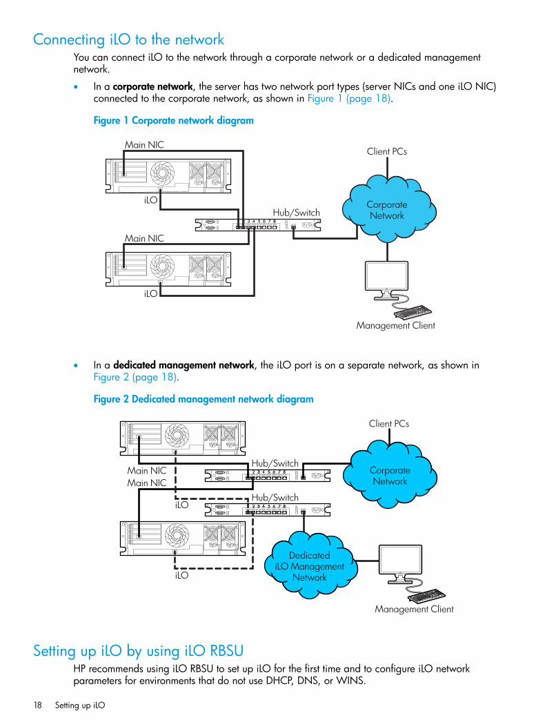
Connecting iLO to the networkYou can connect iLO to the network through a corporate network or a dedicated managementnetwork.
• In a corporate network, the server has two network port types (server NICs and one iLO NIC)connected to the corporate network, as shown in Figure 1 (page 18).
Figure 1 Corporate network diagram
Main NIC
iLO
Main NIC
Hub/Switch
Client PCs
CorporateNetwork
Management Client
iLO
• In a dedicated management network, the iLO port is on a separate network, as shown inFigure 2 (page 18).
Figure 2 Dedicated management network diagram
Hub/SwitchMain NIC
iLO
iLO
Main NICHub/Switch
Client PCs
CorporateNetwork
DedicatediLO Management
Network
Management Client
Setting up iLO by using iLO RBSUHP recommends using iLO RBSU to set up iLO for the first time and to configure iLO networkparameters for environments that do not use DHCP, DNS, or WINS.
18 Setting up iLO
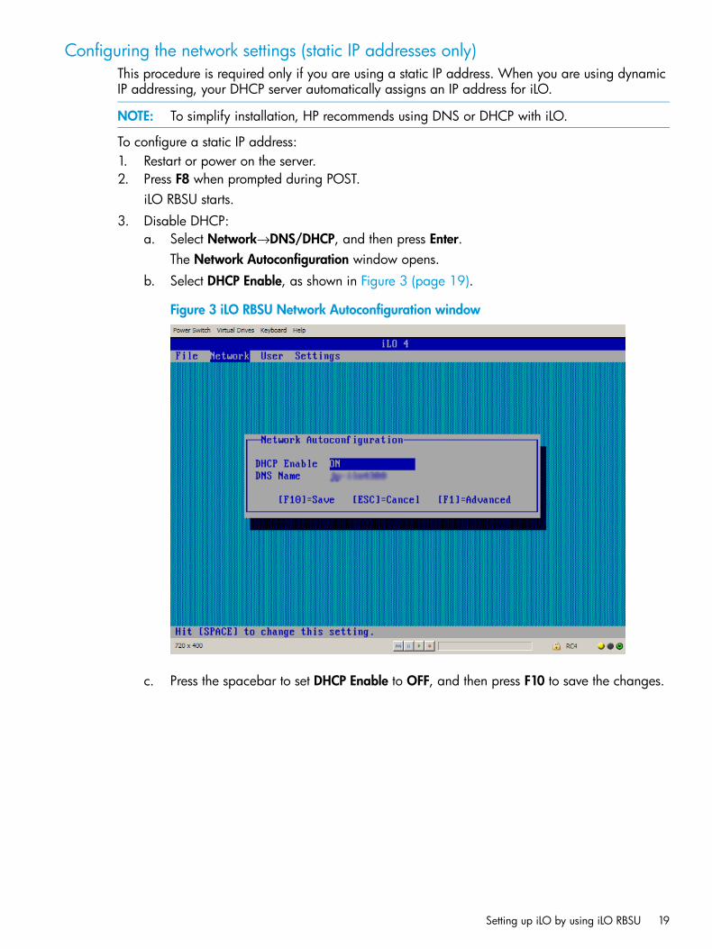
Configuring the network settings (static IP addresses only)This procedure is required only if you are using a static IP address. When you are using dynamicIP addressing, your DHCP server automatically assigns an IP address for iLO.
NOTE: To simplify installation, HP recommends using DNS or DHCP with iLO.
To configure a static IP address:1. Restart or power on the server.2. Press F8 when prompted during POST.
iLO RBSU starts.3. Disable DHCP:
a. Select Network→DNS/DHCP, and then press Enter.The Network Autoconfiguration window opens.
b. Select DHCP Enable, as shown in Figure 3 (page 19).
Figure 3 iLO RBSU Network Autoconfiguration window
c. Press the spacebar to set DHCP Enable to OFF, and then press F10 to save the changes.
Setting up iLO by using iLO RBSU 19
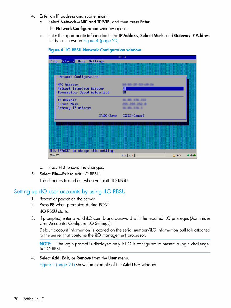
4. Enter an IP address and subnet mask:a. Select Network→NIC and TCP/IP, and then press Enter.
The Network Configuration window opens.b. Enter the appropriate information in the IP Address, Subnet Mask, and Gateway IP Address
fields, as shown in Figure 4 (page 20).
Figure 4 iLO RBSU Network Configuration window
c. Press F10 to save the changes.5. Select File→Exit to exit iLO RBSU.
The changes take effect when you exit iLO RBSU.
Setting up iLO user accounts by using iLO RBSU1. Restart or power on the server.2. Press F8 when prompted during POST.
iLO RBSU starts.3. If prompted, enter a valid iLO user ID and password with the required iLO privileges (Administer
User Accounts, Configure iLO Settings).Default account information is located on the serial number/iLO information pull tab attachedto the server that contains the iLO management processor.
NOTE: The login prompt is displayed only if iLO is configured to present a login challengein iLO RBSU.
4. Select Add, Edit, or Remove from the User menu.Figure 5 (page 21) shows an example of the Add User window.
20 Setting up iLO
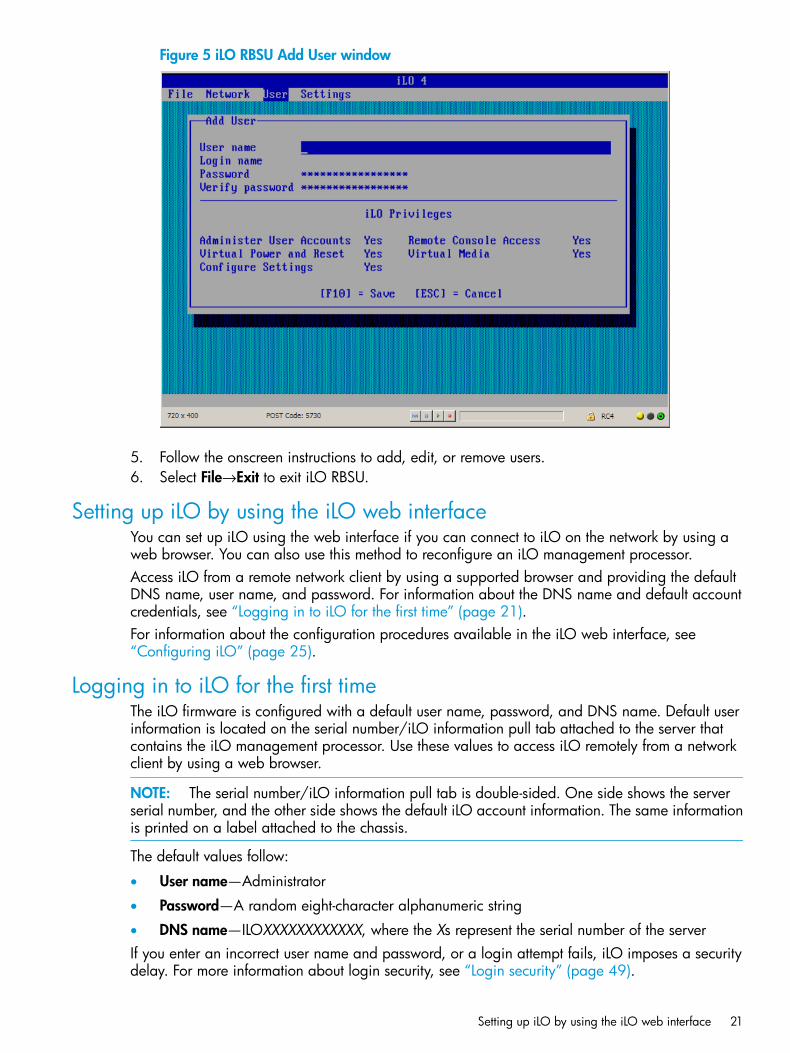
Figure 5 iLO RBSU Add User window
5. Follow the onscreen instructions to add, edit, or remove users.6. Select File→Exit to exit iLO RBSU.
Setting up iLO by using the iLO web interfaceYou can set up iLO using the web interface if you can connect to iLO on the network by using aweb browser. You can also use this method to reconfigure an iLO management processor.Access iLO from a remote network client by using a supported browser and providing the defaultDNS name, user name, and password. For information about the DNS name and default accountcredentials, see “Logging in to iLO for the first time” (page 21).For information about the configuration procedures available in the iLO web interface, see“Configuring iLO” (page 25).
Logging in to iLO for the first timeThe iLO firmware is configured with a default user name, password, and DNS name. Default userinformation is located on the serial number/iLO information pull tab attached to the server thatcontains the iLO management processor. Use these values to access iLO remotely from a networkclient by using a web browser.
NOTE: The serial number/iLO information pull tab is double-sided. One side shows the serverserial number, and the other side shows the default iLO account information. The same informationis printed on a label attached to the chassis.
The default values follow:
• User name—Administrator
• Password—A random eight-character alphanumeric string
• DNS name—ILOXXXXXXXXXXXX, where the Xs represent the serial number of the serverIf you enter an incorrect user name and password, or a login attempt fails, iLO imposes a securitydelay. For more information about login security, see “Login security” (page 49).
Setting up iLO by using the iLO web interface 21
IMPORTANT: HP recommends changing the default values after you log in to iLO for the firsttime. For instructions, see “Administering users” (page 33).
Activating iLO licensed featuresTo activate iLO licensed features, install an HP iLO license. iLO licenses activate functionality suchas graphical Remote Console with multi-user collaboration, video record/playback, and manymore advanced features. For licensing information and installation instructions, see “iLO licensing”(page 32).
Installing the iLO driversiLO is an independent microprocessor running an embedded operating system. The architectureensures that the majority of iLO functionality is available, regardless of the host operating system.The iLO drivers enable software such as HPONCFG and the Agentless Management Service tocommunicate with iLO. Your OS and system configuration determine the driver requirements.The iLO drivers are available from the HP Service Pack for ProLiant (Windows, Red Hat, and SLES)and the HP website (Windows, Linux, and VMware).
• For Windows, Red Hat, and SLES—Download the SPP from http://www.hp.com/go/spp/download and use it to install the iLO drivers.For information about using the SPP, see the SPP documentation.
• For Windows, Red Hat, and SLES—Download the iLO drivers from the HP Support Center:1. Navigate to the technical support page on the HP website: http://www.hp.com/support.2. Select a country or region.
The HP Support page opens.3. Click the Drivers & Downloads link.4. In the search box, enter the server model that you are using (for example, DL360p).
A list of servers is displayed.5. Click the link for your server.
The HP Support Center page for the server opens.6. Click the link for the server operating system.7. Download the iLO drivers.
• For VMware—Download the iLO drivers from the vibsdepot section of the Software DeliveryRepository website at http://downloads.linux.hp.com/SDR/index.html.
• For Ubuntu—Download the iLO drivers from the mcp section of the Software Delivery Repositoryat http://downloads.linux.hp.com/SDR/index.html.
Follow the installation instructions provided with the downloaded software.For OS-specific driver information, see the following:
• “Microsoft device driver support” (page 23)
• “Linux device driver support” (page 23)
• “VMware device driver support” (page 24)
22 Setting up iLO
Microsoft device driver supportWhen you are using Windows with iLO, the following drivers are available:
• HP ProLiant iLO 3/4 Channel Interface Driver for Windows—This driver is required for theoperating system to communicate with iLO. Install this driver in all configurations.
• HP ProLiant iLO 3/4 Management Controller Driver Package for Windows—This packageincludes the following components:
◦ hpqilo3core.sys provides iLO Management Controller Driver support.
◦ ProLiantMonitor.exe provides the HP ProLiant Health Monitor Service and HPProLiant System Shutdown Service.
◦ hpqilo3whea.sys is a helper service for Windows Hardware Error Architecture, whichpasses information between iLO and the operating system in the event of a hardwarefault.
IMPORTANT: The Management Controller Driver Package is required to support AutomaticServer Recovery and the HP Insight Management Agents or HP Insight Management WBEMProviders (if installed). For more information, see “Configuring iLO Management settings”(page 87).
Linux device driver supportWhen you are using Linux with iLO, the following drivers are available:
• HP ProLiant Channel Interface Device Driver (hpilo)—This driver manages agent and toolapplication access to iLO.
• HP System Health Application and Command Line Utilities (hp-health)—A collection ofapplications and tools that enables monitoring of fans, power supplies, temperature sensors,and other management events. This RPM contains the hpasmd, hpasmlited, hpasmpld,and hpasmxld daemons.
Loading and removing SLES and Red Hat drivers:
IMPORTANT: These drivers are standard for SLES 11, Red Hat 5, and Red Hat 6.
Use the following commands to load the iLO drivers:rpm -ivh hpilo-<d.vv.v-pp.Linux_version.arch>.rpm
rpm -ivh hp-health-<d.vv.v-pp.Linux_version.arch>.rpm
Where d is the Linux distribution and version, <vv.v-pp> are version numbers, and <arch> is thearchitecture (i386 or x86_64).Use the following commands to remove the iLO drivers:rpm -e hpilo
rpm -e hp-health
Loading and removing Ubuntu drivers:HP recommends subscribing to the Management Component Pack repository to ensure that yourUbuntu systems have the latest HP software.
IMPORTANT: For open-source Linux distributions (Ubuntu, Debian, Fedora, and others), thehpilo driver is part of the Linux kernel, so the driver is loaded automatically at startup.Use the following procedure to load the HP System Health Application and Command Line Utilities:
Installing the iLO drivers 23
1. Subscribe to the MCP.For instructions, see the following HP website: http://downloads.linux.hp.com/SDR/project/mcp/.
2. Enter the following command to update the repository cache: apt-get update.3. Enter the following command to install the HP System Health Application and Command Line
Utilities: apt-get install hp-health.Use the following command to remove the HP System Health Application and Command LineUtilities:apt-get remove hp-health
VMware device driver supportWhen you are using VMware with iLO, the following driver is available:HP ProLiant Channel Interface Device Driver (hpilo)—This driver manages agent, WBEM provider,and tool application access to iLO. It is included in the customized HP VMware images. For rawVMware images, the driver must be installed manually.
24 Setting up iLO
3 Configuring iLOTypically, an advanced or administrative user who manages users and configures global andnetwork settings configures iLO. This guide provides information about configuring iLO by usingthe iLO web interface and iLO RBSU.
TIP: You can also perform many iLO configuration tasks by using XML configuration and controlscripts or SMASH CLP. For information about using these methods, see the HP iLO 4 Scripting andCommand Line Guide, HP Scripting Toolkit for Linux User Guide, and HP Scripting Toolkit forWindows User Guide.
Updating firmwareFirmware updates enhance server and iLO functionality with new features, improvements, andsecurity updates.Users who have the Configure iLO Settings privilege or host operating system Administrator/rootprivileges can update firmware. If the iLO Security Override Switch is set, any out-of-band usercan update firmware.You can update the following types of firmware on the Firmware Update page:
• iLO
• HP ProLiant System ROM
• System Programmable Logic Device
• SL Chassis FirmwareYou can update firmware by using an online or offline method. For more information, see “Updatingfirmware by using an online method” (page 25) or “Updating firmware by using an offline method”(page 26)
Updating firmware by using an online methodWhen you use an online method to update the firmware, no server reboot is required. You canupdate the firmware and reset iLO without affecting the availability of the server host operatingsystem. The online update method can be performed in-band or out-of-band.
Performing an in-band firmware updateWhen you use this method to update the iLO firmware, the iLO firmware is sent to iLO directlyfrom the server host operating system. The HP ProLiant Channel Interface Driver is required forhost-based iLO firmware updates. During a host-based firmware update, the iLO firmware doesnot verify login credentials or user privileges because the host-based utilities require a root login(Linux and VMware) or Administrator login (Windows).You can use the following in-band firmware update methods:
• iLO Online ROM Flash Component—Use an executable file to update iLO while the server isoperating. The executable file contains the installer and the firmware package. You candownload an iLO Online ROM Flash Component from the following HP website: http://www.hp.com/support/ilo4.
• HPONCFG—Use the HP Lights-Out Online Configuration Utility to configure iLO by using XMLscripts. Download the iLO firmware image and the Update_Firmware.xml sample script.Edit the sample script with your setup details, and then run the script.Sample scripts are available at http://www.hp.com/support/ilo4. For more information aboutscripting, see the HP iLO 4 Scripting and Command Line Guide.
Updating firmware 25
For instructions about obtaining the iLO firmware image, see “Obtaining the iLO firmwareimage file” (page 26).
Performing an out-of-band firmware updateWhen you use this method to update the iLO firmware, you use a network connection tocommunicate with iLO directly.You can use the following out-of-band firmware update methods:
• iLO web interface—Download the iLO Online ROM Flash Component and install it by usingthe iLO web interface. For instructions, see “Updating firmware by using a browser” (page 27).
• HPQLOCFG—Use the HP Lights-Out Configuration Utility to configure iLO by using XML scripts.Download the iLO firmware image and the Update_Firmware.xml sample script. Edit thesample script with your setup details, and then run the script.Sample scripts are available at http://www.hp.com/support/ilo4. For more information aboutscripting, see the HP iLO 4 Scripting and Command Line Guide.For instructions about obtaining the iLO firmware image, see “Obtaining the iLO firmwareimage file” (page 26).
• HPLOMIG (also called HP Directories Support for Management Processors)—Download theHP Directories Support for Management Processors executable file to access the directorysupport components. One of the components, HPLOMIG, can be used to discover multipleiLO processors and update their firmware in one step. You do not need to use directoryintegration to take advantage of this feature. For more information, see “Upgrading firmwareon management processors” (page 232).
• SMASH CLP—Access SMASH CLP through the SSH port, and use standard commands to viewfirmware information and update the firmware.For more information about SMASH CLP, see the HP iLO 4 Scripting and Command LineGuide.
Updating firmware by using an offline methodWhen you use an offline method to update the firmware, you must reboot the server by using anoffline utility. Examples of offline firmware updates include the following:
• HP Service Pack for ProLiant—Use the HP Service Pack for ProLiant to install the firmwareupdate. For more information, see the following website: http://www.hp.com/go/spp.
• Windows or Linux Scripting Toolkit—Use the Scripting Toolkit to configure several settingswithin the server and update firmware. This method is useful for deploying to multiple servers.For instructions, see the HP Scripting Toolkit for Linux User Guide or HP Scripting Toolkit forWindows User Guide.
Obtaining the iLO firmware image fileThe .bin file from the iLO Online ROM Flash Component is required for some of the methods youcan use to update the iLO firmware.To download the iLO Online ROM Flash Component file, and then extract the .bin file:1. Navigate to the technical support page on the HP website: http://www.hp.com/support.2. Select a country or region.
The HP Support page opens.3. Click the Drivers & Downloads link.4. In the search box, enter the server model that you are using (for example, DL360p).
A list of servers is displayed.
26 Configuring iLO
5. Click the link for your server.The HP Support Center page for the server opens.
6. Click the link for your server operating system.7. Follow the onscreen instructions to download the iLO Online ROM Flash Component file.8. Double-click the downloaded file, and then click the Extract button.9. Select a location for the extracted files, and then click OK.
The firmware image is a file similar to ilo4_<yyy>.bin, where <yyy> represents thefirmware version.
Obtaining supported server firmware image filesTo obtain the server firmware files to use for updating the server firmware by using a web browser:1. Navigate to the technical support page on the HP website: http://www.hp.com/support.2. Select a country or region.
The HP Support page opens.3. Click the Drivers & Downloads link.4. In the search box, enter the server model that you are using (for example, DL360p).
A list of servers is displayed.5. Click the link for your server.
The HP Support Center page for the server opens.6. Click the link for the server operating system.7. Follow the onscreen instructions to download the firmware Online ROM Flash Component
file.8. Double-click the downloaded file, and then click the Extract button.9. Select a location for the extracted files, and then click OK.
Updating firmware by using a browserYou can update firmware from any network client by using a supported browser. For a list ofsupported browsers, see “Using the iLO web interface” (page 109).To update the server or iLO firmware:1. Obtain the firmware image file. For instructions, see “Obtaining the iLO firmware image file”
(page 26) or “Obtaining supported server firmware image files” (page 27).2. Navigate to the Administration→Firmware page.
The Firmware Update page opens, as shown in Figure 6 (page 28).
Updating firmware 27
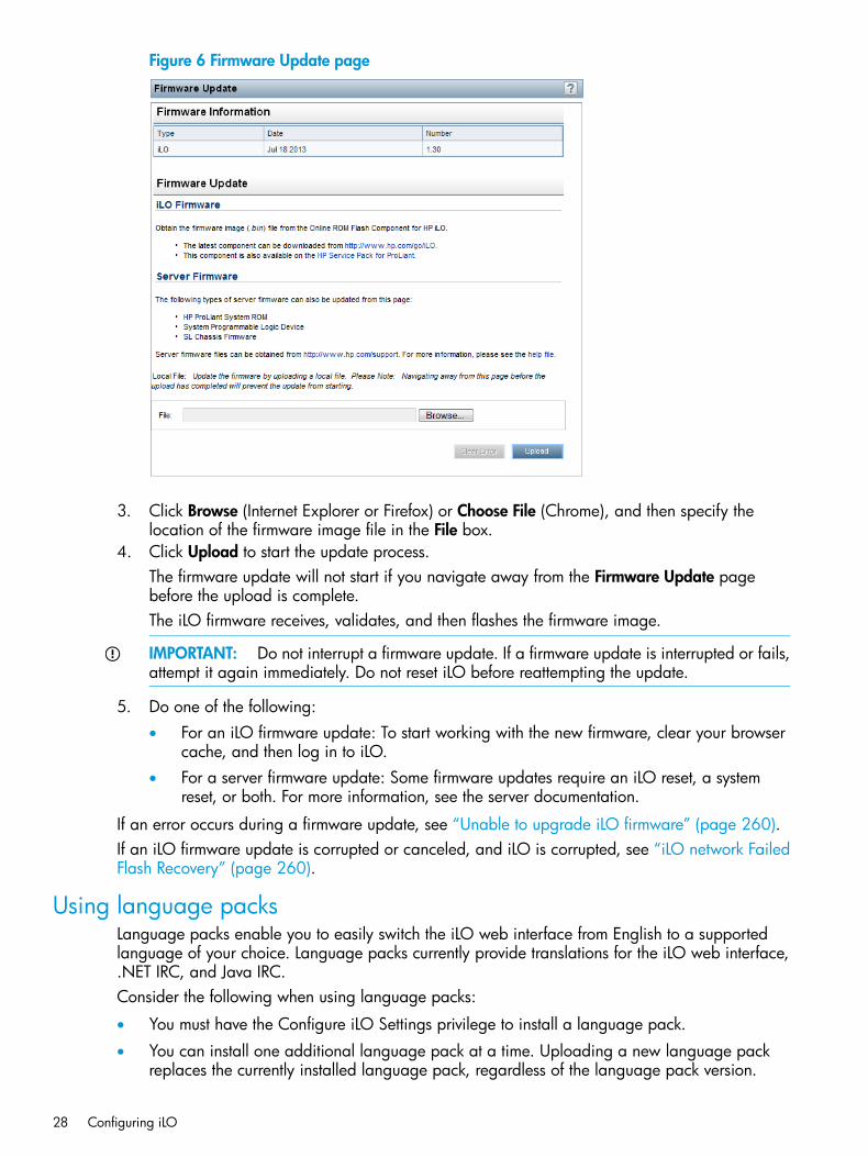
Figure 6 Firmware Update page
3. Click Browse (Internet Explorer or Firefox) or Choose File (Chrome), and then specify thelocation of the firmware image file in the File box.
4. Click Upload to start the update process.The firmware update will not start if you navigate away from the Firmware Update pagebefore the upload is complete.The iLO firmware receives, validates, and then flashes the firmware image.
IMPORTANT: Do not interrupt a firmware update. If a firmware update is interrupted or fails,attempt it again immediately. Do not reset iLO before reattempting the update.
5. Do one of the following:• For an iLO firmware update: To start working with the new firmware, clear your browser
cache, and then log in to iLO.• For a server firmware update: Some firmware updates require an iLO reset, a system
reset, or both. For more information, see the server documentation.
If an error occurs during a firmware update, see “Unable to upgrade iLO firmware” (page 260).If an iLO firmware update is corrupted or canceled, and iLO is corrupted, see “iLO network FailedFlash Recovery” (page 260).
Using language packsLanguage packs enable you to easily switch the iLO web interface from English to a supportedlanguage of your choice. Language packs currently provide translations for the iLO web interface,.NET IRC, and Java IRC.Consider the following when using language packs:
• You must have the Configure iLO Settings privilege to install a language pack.
• You can install one additional language pack at a time. Uploading a new language packreplaces the currently installed language pack, regardless of the language pack version.
28 Configuring iLO

• The language pack firmware is independent of the iLO firmware. Setting iLO to the factorydefault settings does not remove an installed language pack.
• The Java IRC and .NET IRC use the language of the current iLO session.
• For localization support with the Java IRC on Windows systems, you must select the correctlanguage in the Regional and Language Options Control Panel.
• For localization support with the Java IRC on Linux systems, make sure that the fonts for thespecified language are installed and available to the JRE.
• If an installed language pack does not include the translation for a text string, the text isdisplayed in English.
• When you update the iLO firmware, HP recommends downloading the latest language packto ensure that the language pack contents match iLO web interface.iLO 4 firmware version 1.20 or later requires version 1.20 or later of the iLO language pack.
• iLO uses the following process to determine the language of your session:1. If you previously logged in to the iLO web interface on the same computer using the same
browser, and you have not cleared the cookies, the language setting of the last sessionwith that iLO processor is used.
2. If there is no cookie, the current browser language is used if it is supported by iLO andthe required language pack is installed. The supported languages are English (en),Japanese (ja), and Simplified Chinese (zh).
3. Internet Explorer only: If the browser language is not supported, the OS language is usedif the language is supported by iLO, and the required language pack is installed.
4. If there is no cookie, and the browser or OS language is not supported, iLO uses theconfigured default language. For more information, see “Configuring the default languagesettings” (page 31).
Installing a language pack1. Navigate to the iLO software download website: http://www.hp.com/support/ilo4.2. Download the language pack to your local computer.3. Navigate to the Administration→Access Settings→Language page, as shown in Figure 7
(page 30).
Using language packs 29
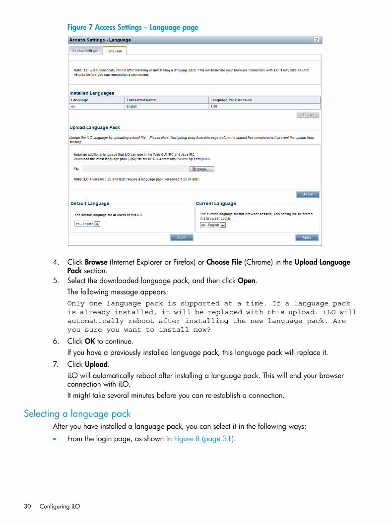
Figure 7 Access Settings – Language page
4. Click Browse (Internet Explorer or Firefox) or Choose File (Chrome) in the Upload LanguagePack section.
5. Select the downloaded language pack, and then click Open.The following message appears:Only one language pack is supported at a time. If a language packis already installed, it will be replaced with this upload. iLO willautomatically reboot after installing the new language pack. Areyou sure you want to install now?
6. Click OK to continue.If you have a previously installed language pack, this language pack will replace it.
7. Click Upload.iLO will automatically reboot after installing a language pack. This will end your browserconnection with iLO.It might take several minutes before you can re-establish a connection.
Selecting a language packAfter you have installed a language pack, you can select it in the following ways:
• From the login page, as shown in Figure 8 (page 31).
30 Configuring iLO
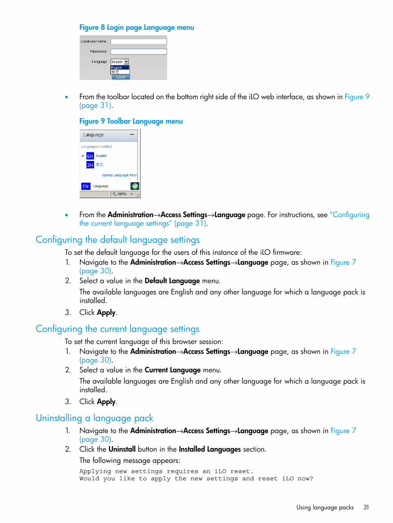
Figure 8 Login page Language menu
• From the toolbar located on the bottom right side of the iLO web interface, as shown in Figure 9(page 31).
Figure 9 Toolbar Language menu
• From the Administration→Access Settings→Language page. For instructions, see “Configuringthe current language settings” (page 31).
Configuring the default language settingsTo set the default language for the users of this instance of the iLO firmware:1. Navigate to the Administration→Access Settings→Language page, as shown in Figure 7
(page 30).2. Select a value in the Default Language menu.
The available languages are English and any other language for which a language pack isinstalled.
3. Click Apply.
Configuring the current language settingsTo set the current language of this browser session:1. Navigate to the Administration→Access Settings→Language page, as shown in Figure 7
(page 30).2. Select a value in the Current Language menu.
The available languages are English and any other language for which a language pack isinstalled.
3. Click Apply.
Uninstalling a language pack1. Navigate to the Administration→Access Settings→Language page, as shown in Figure 7
(page 30).2. Click the Uninstall button in the Installed Languages section.
The following message appears:Applying new settings requires an iLO reset. Would you like to apply the new settings and reset iLO now?
Using language packs 31
3. Click OK to continue.iLO resets and closes your browser connection.It might take several minutes before you can re-establish a connection.
iLO licensingHP iLO standard features are included in every HP ProLiant server to simplify server setup, engagehealth monitoring, monitor power and thermal control, and promote remote administration.HP iLO licenses activate functionality such as graphical Remote Console with multiuser collaboration,video record/playback, and many more advanced features.Unlocking iLO licensed features has never been easier. Simply choose and install the license thatbest suits your company's infrastructure.The following license types are available:
• iLO Advanced—Enables the full set of iLO features. iLO Advanced is available for all HPProLiant Gen8 servers.
◦ iLO Advanced Single Server License
◦ iLO Advanced Electronic License
◦ iLO Advanced Flexible Quantity License
◦ iLO Advanced Volume License
• iLO Essentials—Enables the iLO Integrated Remote Console, Virtual Media, and email alerts.HP iLO Essentials is available on all HP ProLiant Gen8 e-series servers.
• iLO Scale-Out—Enables the following iLO remote management features: Textcons, PowerManagement, Virtual Serial Port log, e-mail alerts, and Remote Syslog. HP iLO Scale-Out isavailable on all HP ProLiant Gen8 SL and BL servers.
For details on purchasing licenses, see the following website: http://www.hp.com/go/ilo/licensing.For a list of the features that are included with each license, see “iLO license options” (page 269).Consider the following about iLO licenses:
• iLO licenses are versionless, meaning, regardless of the version of iLO you have enabled (iLO2, iLO 3, or iLO 4), an iLO license can be applied. For features that are specific to the versionof iLO on your ProLiant server, see “iLO license options” (page 269).
• If you purchase an iLO license with any Insight Control software suite, HP provides the TechnicalSupport and Update Service. For more information, see “Support and other resources”(page 265).
• If you purchase an iLO license as a one-time activation of licensed features, you must purchasefuture functional upgrades.
• One iLO license is required for each server on which the product is installed and used. Licensesare not transferable. You cannot license an HP ProLiant SL/ML/DL server by using aBladeSystem license.
• HP will continue to provide maintenance releases with fixes, as well as iLO standard featureenhancements, at no extra charge.
Free iLO 60-day evaluation licenseA free iLO evaluation license is available for download from the following HP website: http://www.hp.com/go/tryinsightcontrol .
32 Configuring iLO
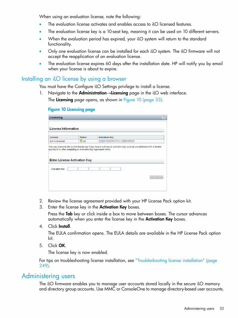
When using an evaluation license, note the following:
• The evaluation license activates and enables access to iLO licensed features.
• The evaluation license key is a 10-seat key, meaning it can be used on 10 different servers.
• When the evaluation period has expired, your iLO system will return to the standardfunctionality.
• Only one evaluation license can be installed for each iLO system. The iLO firmware will notaccept the reapplication of an evaluation license.
• The evaluation license expires 60 days after the installation date. HP will notify you by emailwhen your license is about to expire.
Installing an iLO license by using a browserYou must have the Configure iLO Settings privilege to install a license.1. Navigate to the Administration→Licensing page in the iLO web interface.
The Licensing page opens, as shown in Figure 10 (page 33).
Figure 10 Licensing page
2. Review the license agreement provided with your HP License Pack option kit.3. Enter the license key in the Activation Key boxes.
Press the Tab key or click inside a box to move between boxes. The cursor advancesautomatically when you enter the license key in the Activation Key boxes.
4. Click Install.The EULA confirmation opens. The EULA details are available in the HP License Pack optionkit.
5. Click OK.The license key is now enabled.
For tips on troubleshooting license installation, see “Troubleshooting license installation” (page249).
Administering usersThe iLO firmware enables you to manage user accounts stored locally in the secure iLO memoryand directory group accounts. Use MMC or ConsoleOne to manage directory-based user accounts.
Administering users 33
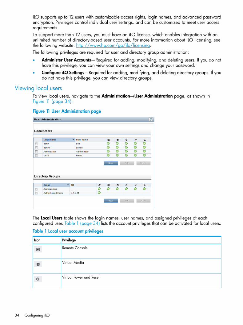
iLO supports up to 12 users with customizable access rights, login names, and advanced passwordencryption. Privileges control individual user settings, and can be customized to meet user accessrequirements.To support more than 12 users, you must have an iLO license, which enables integration with anunlimited number of directory-based user accounts. For more information about iLO licensing, seethe following website: http://www.hp.com/go/ilo/licensing.The following privileges are required for user and directory group administration:
• Administer User Accounts—Required for adding, modifying, and deleting users. If you do nothave this privilege, you can view your own settings and change your password.
• Configure iLO Settings—Required for adding, modifying, and deleting directory groups. If youdo not have this privilege, you can view directory groups.
Viewing local usersTo view local users, navigate to the Administration→User Administration page, as shown inFigure 11 (page 34).
Figure 11 User Administration page
The Local Users table shows the login names, user names, and assigned privileges of eachconfigured user. Table 1 (page 34) lists the account privileges that can be activated for local users.
Table 1 Local user account privileges
PrivilegeIcon
Remote Console
Virtual Media
Virtual Power and Reset
34 Configuring iLO
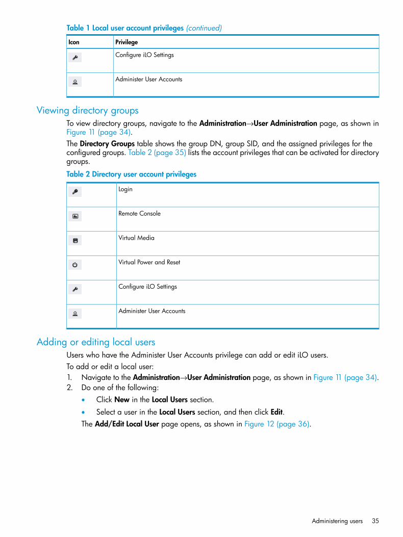
Table 1 Local user account privileges (continued)
PrivilegeIcon
Configure iLO Settings
Administer User Accounts
Viewing directory groupsTo view directory groups, navigate to the Administration→User Administration page, as shown inFigure 11 (page 34).The Directory Groups table shows the group DN, group SID, and the assigned privileges for theconfigured groups. Table 2 (page 35) lists the account privileges that can be activated for directorygroups.
Table 2 Directory user account privileges
Login
Remote Console
Virtual Media
Virtual Power and Reset
Configure iLO Settings
Administer User Accounts
Adding or editing local usersUsers who have the Administer User Accounts privilege can add or edit iLO users.To add or edit a local user:1. Navigate to the Administration→User Administration page, as shown in Figure 11 (page 34).2. Do one of the following:
• Click New in the Local Users section.
• Select a user in the Local Users section, and then click Edit.The Add/Edit Local User page opens, as shown in Figure 12 (page 36).
Administering users 35
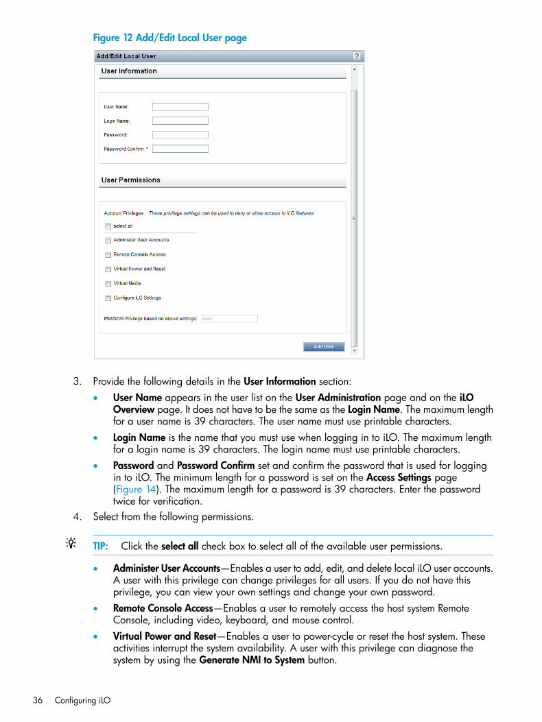
Figure 12 Add/Edit Local User page
3. Provide the following details in the User Information section:• User Name appears in the user list on the User Administration page and on the iLO
Overview page. It does not have to be the same as the Login Name. The maximum lengthfor a user name is 39 characters. The user name must use printable characters.
• Login Name is the name that you must use when logging in to iLO. The maximum lengthfor a login name is 39 characters. The login name must use printable characters.
• Password and Password Confirm set and confirm the password that is used for loggingin to iLO. The minimum length for a password is set on the Access Settings page(Figure 14). The maximum length for a password is 39 characters. Enter the passwordtwice for verification.
4. Select from the following permissions.
TIP: Click the select all check box to select all of the available user permissions.
• Administer User Accounts—Enables a user to add, edit, and delete local iLO user accounts.A user with this privilege can change privileges for all users. If you do not have thisprivilege, you can view your own settings and change your own password.
• Remote Console Access—Enables a user to remotely access the host system RemoteConsole, including video, keyboard, and mouse control.
• Virtual Power and Reset—Enables a user to power-cycle or reset the host system. Theseactivities interrupt the system availability. A user with this privilege can diagnose thesystem by using the Generate NMI to System button.
36 Configuring iLO
• Virtual Media—Enables a user to use the Virtual Media feature on the host system.
• Configure iLO Settings—Enables a user to configure most iLO settings, including securitysettings, and to remotely update the iLO firmware. This privilege does not enable localuser account administration.After iLO is configured, revoking this privilege from all users prevents reconfigurationusing the web interface, HPQLOCFG, or the CLI. Users who have access to iLO RBSUand HPONCFG can still reconfigure iLO. Only a user who has the Administer UserAccounts privilege can enable or disable this privilege.
5. Do one of the following:• Click Add User to add a new user.
• Click Update User to edit a user.
IPMI/DCMI usersThe iLO firmware follows the IPMI 2.0 specification. When you are adding IPMI/DCMI users, thelogin name must be a maximum of 16 characters, and the password must be a maximum of 20characters.When you select iLO user permissions, the equivalent IPMI/DCMI user privilege is displayed inthe IPMI/DCMI Privilege based on above settings box.
• User—A user has read-only access. A user cannot configure or write to iLO, or perform systemactions.For IPMI User privileges: Disable all privileges. Any combination of privileges that does notmeet the Operator level is an IPMI User.
• Operator—An operator can perform system actions, but cannot configure iLO or manage useraccounts.For IPMI Operator privileges: Enable Remote Console Access, Virtual Power and Reset, andVirtual Media. Any combination of privileges greater than Operator that does not meet theAdministrator level is an IPMI Operator.
• Administrator—An administrator has read and write access to all features.For IPMI Administrator privileges: Enable all privileges.
Administering directory groupsiLO enables you to view iLO groups and modify settings for those groups. You must have theConfigure iLO Settings privilege to add or edit directory groups. Use the Add/Edit Directory Grouppage to add or edit iLO directory groups.To add or edit a directory group:1. Navigate to the Administration→User Administration page, as shown in Figure 11 (page 34).2. Do one of the following:
• Click New in the Directory Groups section.
• Select a group in the Directory Groups section, and then click Edit.The Add/Edit Directory Group page opens, as shown in Figure 13 (page 38).
Administering users 37
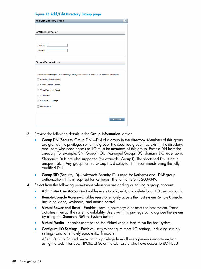
Figure 13 Add/Edit Directory Group page
3. Provide the following details in the Group Information section:• Group DN (Security Group DN)—DN of a group in the directory. Members of this group
are granted the privileges set for the group. The specified group must exist in the directory,and users who need access to iLO must be members of this group. Enter a DN from thedirectory (for example, CN=Group1, OU=Managed Groups, DC=domain, DC=extension).Shortened DNs are also supported (for example, Group1). The shortened DN is not aunique match. Any group named Group1 is displayed. HP recommends using the fullyqualified DN.
• Group SID (Security ID)—Microsoft Security ID is used for Kerberos and LDAP groupauthorization. This is required for Kerberos. The format is S-1-5-2039349.
4. Select from the following permissions when you are adding or editing a group account:• Administer User Accounts—Enables users to add, edit, and delete local iLO user accounts.
• Remote Console Access—Enables users to remotely access the host system Remote Console,including video, keyboard, and mouse control.
• Virtual Power and Reset—Enables users to power-cycle or reset the host system. Theseactivities interrupt the system availability. Users with this privilege can diagnose the systemby using the Generate NMI to System button.
• Virtual Media—Enables users to use the Virtual Media feature on the host system.
• Configure iLO Settings—Enables users to configure most iLO settings, including securitysettings, and to remotely update iLO firmware.After iLO is configured, revoking this privilege from all users prevents reconfigurationusing the web interface, HPQLOCFG, or the CLI. Users who have access to iLO RBSU
38 Configuring iLO
and HPONCFG can still reconfigure iLO. Only a user who has the Administer UserAccounts privilege can enable or disable this privilege.
• Login Privilege—Enables members of a group to log in to iLO.5. Do one of the following:
• Click Add Group to add a new group.
• Click Update Group to edit a group.
Deleting a user or a directory groupThe privilege required for this procedure depends on the user account type.
• To delete a local account, the Administer User Accounts privilege is required.
• To delete a directory group, the Configure iLO Settings privilege is required.To delete an existing user or group:1. Navigate to the Administration→User Administration page, as shown in Figure 11 (page 34).2. Select the check box next to the user or group that you want to delete.3. Click Delete.
A pop-up window opens with one of the following messages:
• Local user: Are you sure you want to delete the selected user(s)?Warning: Always leave at least one administrator.
• Directory group: Are you sure you want to delete the selectedgroup(s)?
4. Click OK.
Configuring iLO access settingsYou can modify iLO access settings, including service, IPMI/DCMI, and access options. The valuesthat you enter on the Access Settings page apply to all iLO users. You must have the Configure iLOSettings privilege to modify access settings.The default configuration is suitable for most operating environments. The values that you canmodify on the Access Settings page allow complete customization of the iLO external access methodsfor specialized environments.
Configuring service settingsThe Service section on the Access Settings page shows the Secure Shell (SSH) Access and SNMPAccess settings and the TCP/IP port values.The TCP/IP ports used by iLO are configurable, which enables compliance with any site requirementsor security initiatives for port settings. These settings do not affect the host system.Changing these settings usually requires configuration of the web browser used for standard andSSL communication. When these settings are changed, iLO initiates a reset to activate the changes.To configure Service settings:
Configuring iLO access settings 39
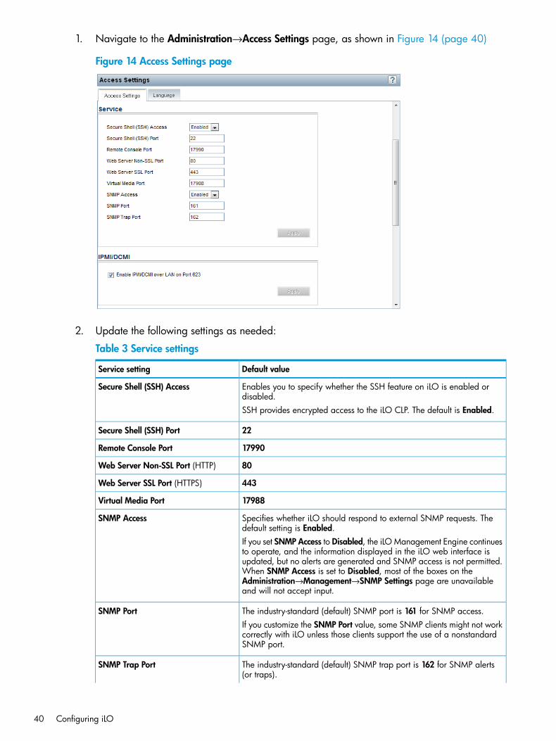
1. Navigate to the Administration→Access Settings page, as shown in Figure 14 (page 40)
Figure 14 Access Settings page
2. Update the following settings as needed:
Table 3 Service settings
Default valueService setting
Enables you to specify whether the SSH feature on iLO is enabled ordisabled.
Secure Shell (SSH) Access
SSH provides encrypted access to the iLO CLP. The default is Enabled.
22Secure Shell (SSH) Port
17990Remote Console Port
80Web Server Non-SSL Port (HTTP)
443Web Server SSL Port (HTTPS)
17988Virtual Media Port
Specifies whether iLO should respond to external SNMP requests. Thedefault setting is Enabled.
SNMP Access
If you set SNMP Access to Disabled, the iLO Management Engine continuesto operate, and the information displayed in the iLO web interface isupdated, but no alerts are generated and SNMP access is not permitted.When SNMP Access is set to Disabled, most of the boxes on theAdministration→Management→SNMP Settings page are unavailableand will not accept input.
The industry-standard (default) SNMP port is 161 for SNMP access.SNMP PortIf you customize the SNMP Port value, some SNMP clients might not workcorrectly with iLO unless those clients support the use of a nonstandardSNMP port.
The industry-standard (default) SNMP trap port is 162 for SNMP alerts(or traps).
SNMP Trap Port
40 Configuring iLO
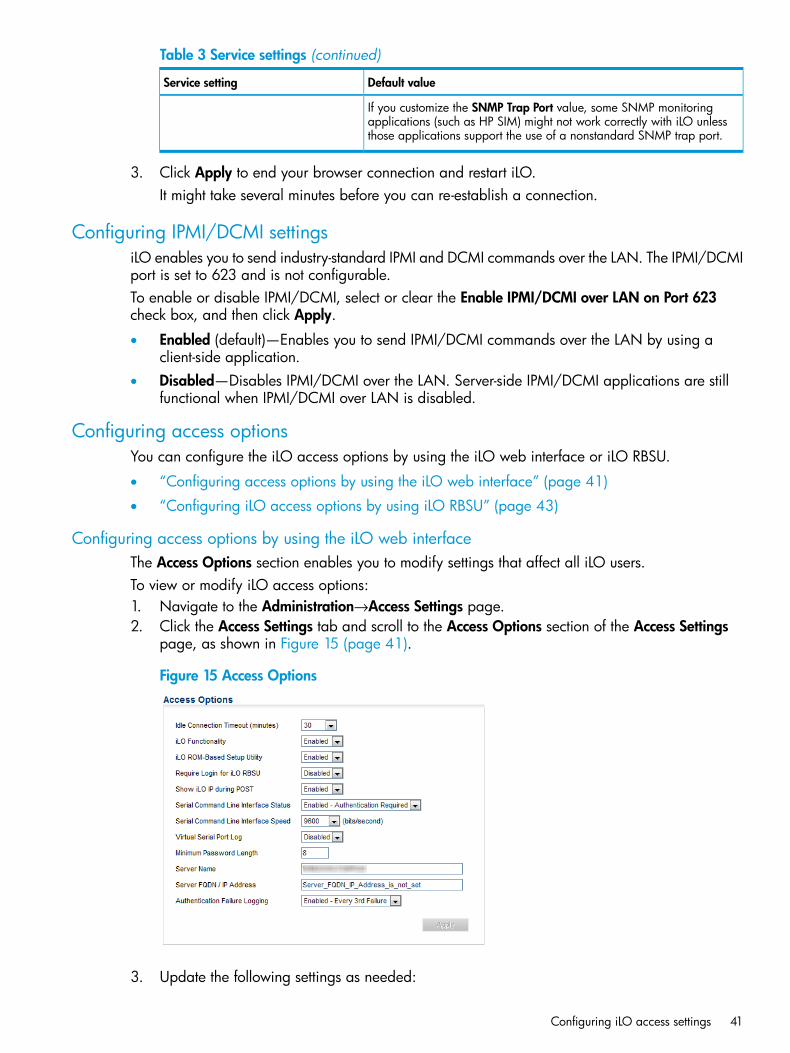
Table 3 Service settings (continued)
Default valueService setting
If you customize the SNMP Trap Port value, some SNMP monitoringapplications (such as HP SIM) might not work correctly with iLO unlessthose applications support the use of a nonstandard SNMP trap port.
3. Click Apply to end your browser connection and restart iLO.It might take several minutes before you can re-establish a connection.
Configuring IPMI/DCMI settingsiLO enables you to send industry-standard IPMI and DCMI commands over the LAN. The IPMI/DCMIport is set to 623 and is not configurable.To enable or disable IPMI/DCMI, select or clear the Enable IPMI/DCMI over LAN on Port 623check box, and then click Apply.
• Enabled (default)—Enables you to send IPMI/DCMI commands over the LAN by using aclient-side application.
• Disabled—Disables IPMI/DCMI over the LAN. Server-side IPMI/DCMI applications are stillfunctional when IPMI/DCMI over LAN is disabled.
Configuring access optionsYou can configure the iLO access options by using the iLO web interface or iLO RBSU.
• “Configuring access options by using the iLO web interface” (page 41)
• “Configuring iLO access options by using iLO RBSU” (page 43)
Configuring access options by using the iLO web interfaceThe Access Options section enables you to modify settings that affect all iLO users.To view or modify iLO access options:1. Navigate to the Administration→Access Settings page.2. Click the Access Settings tab and scroll to the Access Options section of the Access Settings
page, as shown in Figure 15 (page 41).
Figure 15 Access Options
3. Update the following settings as needed:
Configuring iLO access settings 41
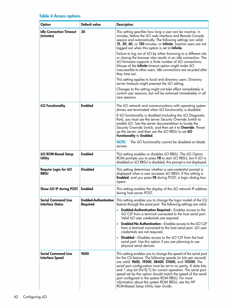
Table 4 Access options
DescriptionDefault valueOption
This setting specifies how long a user can be inactive, inminutes, before the iLO web interface and Remote Console
30Idle Connection Timeout(minutes)
session end automatically. The following settings are valid:15, 30, 60, or 120 minutes, or Infinite. Inactive users are notlogged out when this option is set to Infinite.Failure to log out of iLO by either browsing to a different siteor closing the browser also results in an idle connection. TheiLO firmware supports a finite number of iLO connections.Misuse of the Infinite timeout option might make iLOinaccessible to other users. Idle connections are recycled afterthey time out.This setting applies to local and directory users. Directoryserver timeouts might preempt the iLO setting.Changes to the setting might not take effect immediately incurrent user sessions, but will be enforced immediately in allnew sessions.
The iLO network and communications with operating systemdrivers are terminated when iLO functionality is disabled.
EnablediLO Functionality
If iLO functionality is disabled (including the iLO DiagnosticPort), you must use the server Security Override Switch toenable iLO. See the server documentation to locate theSecurity Override Switch, and then set it to Override. Powerup the server, and then use the iLO RBSU to set iLOFunctionality to Enabled.
NOTE: The iLO functionality cannot be disabled on bladeservers.
This setting enables or disables iLO RBSU. The iLO OptionROM prompts you to press F8 to start iLO RBSU, but if iLO isdisabled or iLO RBSU is disabled, this prompt is not displayed.
EnablediLO ROM-Based SetupUtility
This setting determines whether a user-credential prompt isdisplayed when a user accesses iLO RBSU. If this setting is
DisabledRequire Login for iLORBSU
Enabled, and you press F8 during POST, a login dialog boxopens.
This setting enables the display of the iLO network IP addressduring host server POST.
EnabledShow iLO IP during POST
This setting enables you to change the login model of the CLIfeature through the serial port. The following settings are valid:
Enabled-AuthenticationRequired
Serial Command LineInterface Status
• Enabled-Authentication Required—Enables access to theiLO CLP from a terminal connected to the host serial port.Valid iLO user credentials are required.
• Enabled-No Authentication—Enables access to the iLO CLPfrom a terminal connected to the host serial port. iLO usercredentials are not required.
• Disabled—Disables access to the iLO CLP from the hostserial port. Use this option if you are planning to usephysical serial devices.
This setting enables you to change the speed of the serial portfor the CLI feature. The following speeds (in bits per second)
9600Serial Command LineInterface Speed
are valid: 9600, 19200, 38400, 57600, and 115200. Theserial port configuration must be set to no parity, 8 data bits,and 1 stop bit (N/8/1) for correct operation. The serial portspeed set by this option should match the speed of the serialport configured in the system ROM RBSU. For moreinformation about the system ROM RBSU, see the HPROM-Based Setup Utility User Guide.
42 Configuring iLO
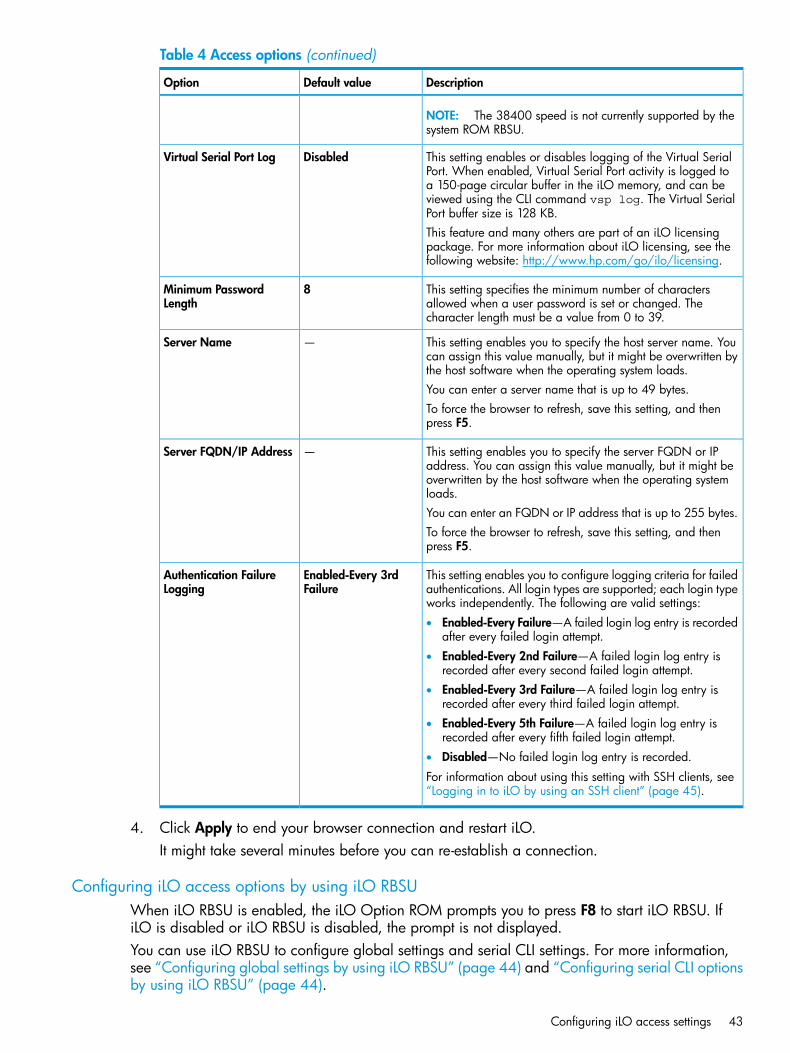
Table 4 Access options (continued)
DescriptionDefault valueOption
NOTE: The 38400 speed is not currently supported by thesystem ROM RBSU.
This setting enables or disables logging of the Virtual SerialPort. When enabled, Virtual Serial Port activity is logged to
DisabledVirtual Serial Port Log
a 150-page circular buffer in the iLO memory, and can beviewed using the CLI command vsp log. The Virtual SerialPort buffer size is 128 KB.This feature and many others are part of an iLO licensingpackage. For more information about iLO licensing, see thefollowing website: http://www.hp.com/go/ilo/licensing.
This setting specifies the minimum number of charactersallowed when a user password is set or changed. Thecharacter length must be a value from 0 to 39.
8Minimum PasswordLength
This setting enables you to specify the host server name. Youcan assign this value manually, but it might be overwritten bythe host software when the operating system loads.
—Server Name
You can enter a server name that is up to 49 bytes.To force the browser to refresh, save this setting, and thenpress F5.
This setting enables you to specify the server FQDN or IPaddress. You can assign this value manually, but it might be
—Server FQDN/IP Address
overwritten by the host software when the operating systemloads.You can enter an FQDN or IP address that is up to 255 bytes.To force the browser to refresh, save this setting, and thenpress F5.
This setting enables you to configure logging criteria for failedauthentications. All login types are supported; each login typeworks independently. The following are valid settings:
Enabled-Every 3rdFailure
Authentication FailureLogging
• Enabled-Every Failure—A failed login log entry is recordedafter every failed login attempt.
• Enabled-Every 2nd Failure—A failed login log entry isrecorded after every second failed login attempt.
• Enabled-Every 3rd Failure—A failed login log entry isrecorded after every third failed login attempt.
• Enabled-Every 5th Failure—A failed login log entry isrecorded after every fifth failed login attempt.
• Disabled—No failed login log entry is recorded.
For information about using this setting with SSH clients, see“Logging in to iLO by using an SSH client” (page 45).
4. Click Apply to end your browser connection and restart iLO.It might take several minutes before you can re-establish a connection.
Configuring iLO access options by using iLO RBSUWhen iLO RBSU is enabled, the iLO Option ROM prompts you to press F8 to start iLO RBSU. IfiLO is disabled or iLO RBSU is disabled, the prompt is not displayed.You can use iLO RBSU to configure global settings and serial CLI settings. For more information,see “Configuring global settings by using iLO RBSU” (page 44) and “Configuring serial CLI optionsby using iLO RBSU” (page 44).
Configuring iLO access settings 43
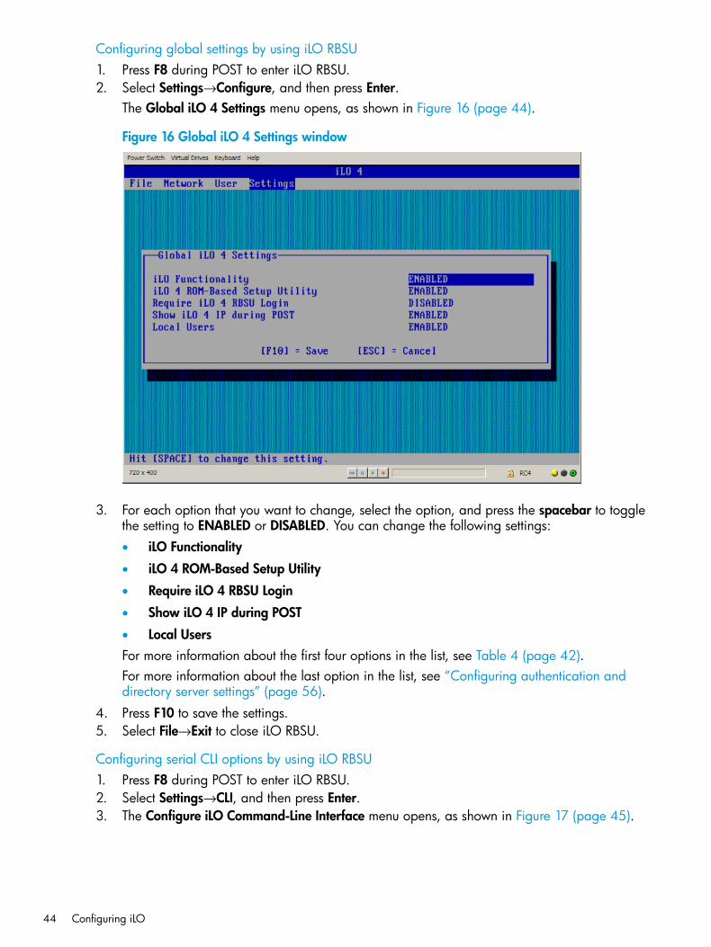
Configuring global settings by using iLO RBSU1. Press F8 during POST to enter iLO RBSU.2. Select Settings→Configure, and then press Enter.
The Global iLO 4 Settings menu opens, as shown in Figure 16 (page 44).
Figure 16 Global iLO 4 Settings window
3. For each option that you want to change, select the option, and press the spacebar to togglethe setting to ENABLED or DISABLED. You can change the following settings:• iLO Functionality
• iLO 4 ROM-Based Setup Utility
• Require iLO 4 RBSU Login
• Show iLO 4 IP during POST
• Local UsersFor more information about the first four options in the list, see Table 4 (page 42).For more information about the last option in the list, see “Configuring authentication anddirectory server settings” (page 56).
4. Press F10 to save the settings.5. Select File→Exit to close iLO RBSU.
Configuring serial CLI options by using iLO RBSU1. Press F8 during POST to enter iLO RBSU.2. Select Settings→CLI, and then press Enter.3. The Configure iLO Command-Line Interface menu opens, as shown in Figure 17 (page 45).
44 Configuring iLO
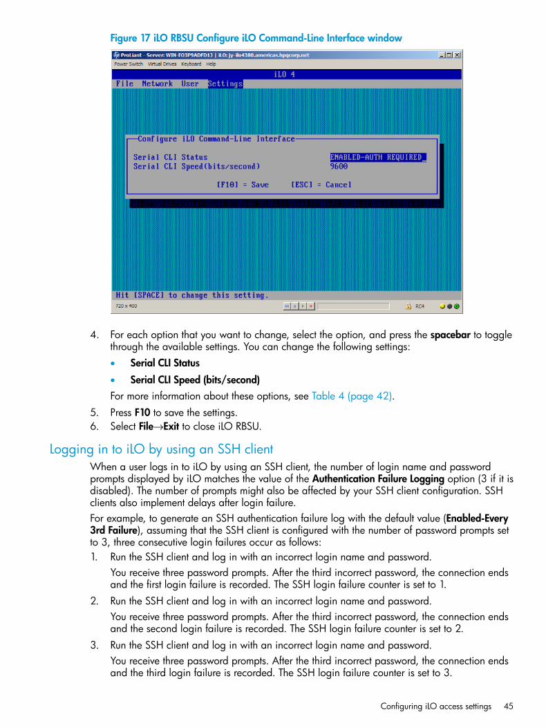
Figure 17 iLO RBSU Configure iLO Command-Line Interface window
4. For each option that you want to change, select the option, and press the spacebar to togglethrough the available settings. You can change the following settings:• Serial CLI Status
• Serial CLI Speed (bits/second)For more information about these options, see Table 4 (page 42).
5. Press F10 to save the settings.6. Select File→Exit to close iLO RBSU.
Logging in to iLO by using an SSH clientWhen a user logs in to iLO by using an SSH client, the number of login name and passwordprompts displayed by iLO matches the value of the Authentication Failure Logging option (3 if it isdisabled). The number of prompts might also be affected by your SSH client configuration. SSHclients also implement delays after login failure.For example, to generate an SSH authentication failure log with the default value (Enabled-Every3rd Failure), assuming that the SSH client is configured with the number of password prompts setto 3, three consecutive login failures occur as follows:1. Run the SSH client and log in with an incorrect login name and password.
You receive three password prompts. After the third incorrect password, the connection endsand the first login failure is recorded. The SSH login failure counter is set to 1.
2. Run the SSH client and log in with an incorrect login name and password.You receive three password prompts. After the third incorrect password, the connection endsand the second login failure is recorded. The SSH login failure counter is set to 2.
3. Run the SSH client and log in with an incorrect login name and password.You receive three password prompts. After the third incorrect password, the connection endsand the third login failure is recorded. The SSH login failure counter is set to 3.
Configuring iLO access settings 45
The iLO firmware records an SSH failed login log entry, and sets the SSH login failure counter to0.
Configuring iLO securityiLO provides the following security features:
• User-defined TCP/IP ports. For more information, see “Configuring iLO access settings”(page 39).
• User actions logged in the iLO Event Log. For more information, see “Using the iLO Event Log”(page 133).
• Progressive delays for failed login attempts. For more information, see “Login security”(page 49).
• Support for X.509 CA signed certificates. For more information, see “Administering SSLcertificates” (page 52).
• Support for securing iLO RBSU. For more information, see “iLO RBSU security” (page 47).
• Encrypted communication that uses SSL certificate administration. For more information, see“Administering SSL certificates” (page 52).
• Support for optional LDAP-based directory services. For more information, see “Directoryservices” (page 193).
Some of these options are licensed features. For more information, see “iLO licensing” (page 32).
General security guidelinesGeneral security guidelines for iLO follow:
• For maximum security, configure iLO on a separate management network. For more information,see “Connecting iLO to the network” (page 18).
• Do not connect iLO directly to the Internet.
• Use a browser that has a 128-bit cipher strength.
PasswordsHP recommends that you follow these password guidelines:
• Passwords should:
Never be written down or recorded◦◦ Never be shared with others
◦ Not be words found in a dictionary
◦ Not be obvious words, such as the company name, product name, user name, or loginname
• Passwords should have at least three of the following characteristics:
One numeric character◦◦ One special character
◦ One lowercase character
◦ One uppercase character
46 Configuring iLO
Depending on the Minimum Password Length setting on the Access Settings page, the passwordcan have a minimum of zero characters (no password) and a maximum of 39 characters. Thedefault Minimum Password Length is eight characters.
IMPORTANT: HP does not recommend setting the Minimum Password Length to fewer than eightcharacters unless you have a physically secure management network that does not extend outsidethe secure data center. For information about setting the Minimum Password Length, see“Configuring access options by using the iLO web interface” (page 41).
iLO RBSU securityiLO RBSU enables you to view and modify the iLO configuration. You can configure iLO RBSUaccess settings by using iLO RBSU, a web browser, RIBCL scripts, or the iLO Security OverrideSwitch.
• For information about using a web browser to configure iLO RBSU access settings, see“Configuring access options by using the iLO web interface” (page 41).
• For information about using iLO RBSU to configure iLO RBSU access settings, see “ConfiguringiLO access options by using iLO RBSU” (page 43).
• For information about using RIBCL scripts to configure iLO RBSU, see the HP iLO 4 Scriptingand Command Line Guide.
• For information about using the iLO Security Override Switch to configure iLO RBSU, see “iLOSecurity Override Switch administration” (page 48).
iLO RBSU has the following security levels:
• RBSU Login Not Required (default)Anyone who has access to the host during POST can enter iLO RBSU to view and modifyconfiguration settings. This is an acceptable setting if host access is controlled. If host accessis not controlled, any user can make changes by using the active configuration menus.To change this setting:
◦ Use the iLO web interface to edit the Require Login for iLO RBSU setting. For instructions,see “Configuring access options by using the iLO web interface” (page 41).
◦ Use the iLO RBSU to edit the Require iLO 4 RBSU Login setting. For instructions, see“Configuring iLO access options by using iLO RBSU” (page 43).
• RBSU Login Required (more secure)If iLO RBSU login is required, the active configuration menus are controlled by the authenticateduser access rights.To change this setting:
◦ Use the iLO web interface to edit the Require Login for iLO RBSU setting. For instructions,see “Configuring access options by using the iLO web interface” (page 41).
◦ Use the iLO RBSU to edit the Require iLO 4 RBSU Login setting. For instructions, see“Configuring iLO access options by using iLO RBSU” (page 43).
• RBSU Disabled (most secure)If iLO RBSU is disabled, user access is prohibited. This prevents modification using the iLORBSU interface.
Configuring iLO security 47
To change this setting:
◦ Use the iLO web interface to edit the iLO ROM-Based Setup Utility setting. For instructions,see “Configuring access options by using the iLO web interface” (page 41).
◦ Use the iLO RBSU to edit the iLO 4 ROM-Based Setup Utility setting. For instructions, see“Configuring iLO access options by using iLO RBSU” (page 43).
iLO Security Override Switch administrationThe iLO Security Override Switch grants the administrator full access to the iLO processor. Thisaccess might be necessary for any of the following conditions:
• iLO has been disabled and must be re-enabled.
• All user accounts that have the Administer User Accounts privilege are locked out.
• An invalid configuration prevents iLO from being displayed on the network, and iLO RBSU isdisabled.
• The boot block must be flashed.
• The iLO NIC is turned off, and running iLO RBSU to turn it back on is not possible or convenient.
• Only one user name is configured, and the password is forgotten.Ramifications of setting the iLO Security Override Switch include the following:
• All security authorization verifications are disabled when the switch is set.
• iLO RBSU runs if the host server is reset.
• iLO is not disabled and might be displayed on the network as configured.
• iLO, if disabled when the switch is set, does not log out the user and complete the disableprocess until the power is cycled on the server.
• The boot block is exposed for programming.
• A warning message is displayed on iLO web interface pages, indicating that the switch iscurrently in use.
• An iLO log entry records the use of the switch.When iLO boots after you set or clear the iLO Security Override Switch, an SNMP alert is sent ifan SNMP Alert Destination is configured.Setting the iLO Security Override Switch enables you to flash the iLO boot block. HP does notanticipate that you will need to update the boot block. However, if an update is required, you mustbe physically present at the server to reprogram the boot block and reset iLO. The boot block isexposed until iLO is reset. For maximum security, HP recommends disconnecting iLO from thenetwork until the reset is complete. You must open the server enclosure to access the iLO SecurityOverride Switch.To set the iLO Security Override Switch:1. Power off the server.2. Set the switch.3. Power on the server.Reverse this procedure to clear the iLO Security Override Switch.The iLO Security Override Switch uses switch #1 on the DIP switch panel. For information aboutaccessing the iLO Security Override Switch, see the server documentation or use the diagrams onthe server access panel.
48 Configuring iLO
TPM supportA TPM is a computer chip that securely stores artifacts used to authenticate the platform. Theseartifacts can include passwords, certificates, or encryption keys. You can also use a TPM to storeplatform measurements to make sure that the platform remains trustworthy.On a supported system, iLO decodes the TPM record and passes the configuration status to iLO,the CLP, and the XML interface. The iLO Overview page displays the following TPM statusinformation:
• Not Supported—A TPM is not supported.
• Not Present—A TPM is not installed.
• Present—This indicates one of the following statuses:
A TPM is installed but is disabled.◦◦ A TPM is installed and enabled.
◦ A TPM is installed and enabled, and Expansion ROM measuring is enabled. If ExpansionROM measuring is enabled, the Update Firmware page displays a legal warning messagewhen you click Upload.
User accounts and accessiLO supports the configuration of up to 12 local user accounts. Each account can be managedthrough the following features:
• Privileges
• Login securityYou can configure iLO to use a directory to authenticate and authorize its users. This configurationenables an unlimited number of users and easily scales to the number of iLO devices in an enterprise.The directory also provides a central point of administration for iLO devices and users, and thedirectory can enforce a stronger password policy. iLO enables you to use local users, directoryusers, or both.The following directory configuration options are available:
• A directory extended with HP schema
• The directory default schemaFor more information about using directory authentication, see “Directory services” (page 193).
User privilegesiLO allows you to control user account access to iLO features through the use of privileges. Whena user attempts to use a feature, iLO verifies that the user has the proper privilege to use thatfeature.You can control access to iLO features by using the following privileges: Administer User Accounts,Remote Console Access, Virtual Power and Reset, Virtual Media, and Configure iLO Settings. Userprivileges are configured on the Administration→User Administration page. For more information,see “Administering users” (page 33).
NOTE: User accounts can also be configured by using iLO RBSU. For more information, see“Setting up iLO user accounts by using iLO RBSU” (page 20).
Login securityiLO provides several login security features. After an initial failed login attempt, iLO imposes adelay of ten seconds. Each subsequent failed attempt increases the delay by ten seconds. An
Configuring iLO security 49
information page is displayed during each delay; this continues until a valid login occurs. Thisfeature helps to prevent dictionary attacks against the browser login port.iLO saves a detailed log entry for failed login attempts. You can configure the Authentication FailureLogging frequency on the Administration→Access Settings page. For more information, see“Configuring access options by using the iLO web interface” (page 41).
Administering SSH keysThe Secure Shell Key page (Figure 18) displays the hash of the SSH public key associated witheach user. Each user can have only one key assigned. Use this page to view, add, or delete SSHkeys.You must have the Administer User Accounts privilege to add and delete SSH keys.
About SSH keysWhen you add an SSH key to iLO, you paste the SSH key file into iLO as described in “Authorizinga new key by using the iLO web interface” (page 51) and “Authorizing a new key by using theCLI” (page 52). The file must contain the user-generated public key. The iLO firmware associateseach key with the selected local user account. If a user is removed after an SSH key is authorizedfor that user, the SSH key is removed.The following SSH key formats are supported:
• RFC 4716---- BEGIN SSH2 PUBLIC KEY ---- Comment: "Administrator" AAAAB3NzaC1kc3MAAACAT27C04Dy2zr7fWhUL7TwHDKQdEdyuAlNLIivLFP3IoKZ ZtzF0VInP5x2VFVYmTvdVjD92CTlxxAtarOPON2qUqoOajKRtBWLmxcfqsLCT3wI 3ldxQvPYnhTYyhPQuoeJ/vYhoam+y0zi8D03pDv9KaeNA3H/zEL5mf9Ktgts8/UA AAAVAJ4efo8ffq0hg4a/eTGEuHPCb3INAAAAgCbnhADYXu+Mv4xuXccXWP0Pcj47 7YiZgos3jt/Z0ezFX6/cN/RwwZwPC1HCsMuwsVBIqi7bvn1XczFPKOt06gVWcjFt eBY3/bKpQkn61SGPC8AhSu8ui0KjyUZrxL4LdBrtp/K2+lm1fqXHnzDIEJ0RHg8Z JazhY920PpkD4hNbAAAAgDN3lba1qFVl0UlRjj21MjXgr6em9TETSOO5b7SQ8hX/ Z/axobbrHCj/2s66VA/554chkVimJT2IDRRKVkcV8OVC3nb4ckpfFEZvKkAWYaiF DLqRbHhh4qyRBIfBKQpvvhDj1aecdFbaO2UvZltMir4n8/E0hh19nfi3tjXAtSTV ---- END SSH2 PUBLIC KEY ----
• OpenSSH key format—This format must be one line only.ssh-dss AAAAB3NzaC1kc3MAAACAYjEd8Rk8HLCLqDIlI+RkA1UXjVS28hNSk8YDljTaJpw1VOlBirrLGPdSt0avNSz0DNQuU7gTPfjj/8c XyHe3y95Oa3Rics1fARyLiNFGqFjr7w2ByQuoYUaXBzzghIYMQcmpc/W/kDMC0dVOf2XnfcLpcVDIm3ahVPRkxFV9WKkAAAAVAI 3J61F+oVKrbNovhoHh8pFfUa9LAAAAgA8pU5/M9F0s5QxqkEWPD6+FVz9cZ0GfwIbiuAI/9ARsizkbwRtpAlxAp6eDZKFvj3ZIy NjcQODeYYqOvVU45AkSkLBMGjpF05cVtnWEGEvrW7mAvtG2zwMEDFSREw/V526/jR9TKzSNXTH/wqRtTc/oLotHeyV2jFZFGpxD OvNWAAAAgFf6pvWaco3CDELmH0jT3yUkRSaDztpqtoo4D7ev7VrNPPjnKKKmpzHPmAKRxz3g5S80SfWSnWM3n/pekBa9QI9lH1r 3Lx4JoOVwTpkbwb0by4eZ2cqDw20KQ0A5J84iQE9TbPNecJ0HJtZH/K8YnFNwwYy2NSJyjLwA0TSmQEOW Administrator
• iLO legacy format—OpenSSH keys surrounded by BEGIN/END headers needed for RIBCL.This format must be one line between the BEGIN and END.-----BEGIN SSH KEY----- ssh-dss AAAAB3NzaC1kc3MAAACBANA45qXo9cM1asav6ApuCREt1UvP7qcMbw+sTDrx9lV22XvonwijdFiOM/0VvuzVhM9oKdGMC7sCGQr FV3zWDMJcIb5ZdYQSDt44X6bvlsQcAR0wNGBN9zHL6YsbXvNAsXN7uBM7jXwHwrApWVuGAI0QnwUYvN/dsE8fbEYtGZCRAAAAFQ DofA47q8pIRdr6epnJXSNrwJRvaQAAAIBY7MKa2uH82I0KKYTbNMi0o5mOqmqy+tg5s9GC+HvvYy/S7agpIdfJzqkpHF5EPhm0j KzzVxmsanO+pjju7lrE3xUxojevlokTERSCM xLa+OVVbNcgTe0xpvc/cF6ZvsHs0UWz6gXIMCQ9Pk118VMOw/tyLp42YXOaLZzG fi5pKAAAAIEAl7FsO7sDbPj02a5jO3qFXa762lWvu5iPRZ9cEt5WJEYwMO/ICaJVDWVOpqF9spoNb53Wl1pUARJg1ss8Ruy7YBv 8Z1urWWAF3fYy7R/SlQqrsRYDPLM5eBkkLO28B8C6++HjLuc+hBvj90tsqeNVhpCfO9qrjYomYwnDC4m1IT4= ASmith -----END SSH KEY-----
Note the following when working with SSH keys:
• The previously listed sample formats are supported with the iLO web interface and the CLI.Only the iLO legacy format is supported with RIBCL scripts.
• Any SSH connection authenticated through the corresponding private key is authenticated asthe owner of the key and has the same privileges.
50 Configuring iLO
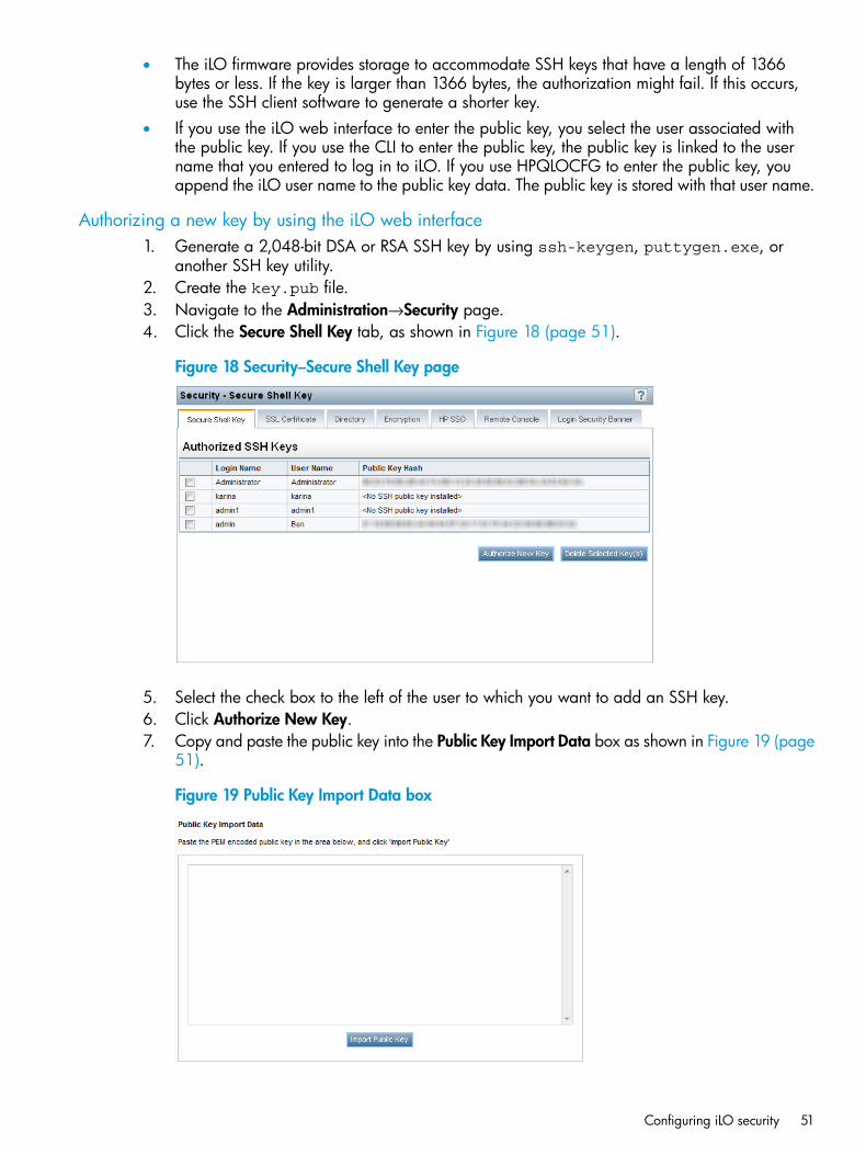
• The iLO firmware provides storage to accommodate SSH keys that have a length of 1366bytes or less. If the key is larger than 1366 bytes, the authorization might fail. If this occurs,use the SSH client software to generate a shorter key.
• If you use the iLO web interface to enter the public key, you select the user associated withthe public key. If you use the CLI to enter the public key, the public key is linked to the username that you entered to log in to iLO. If you use HPQLOCFG to enter the public key, youappend the iLO user name to the public key data. The public key is stored with that user name.
Authorizing a new key by using the iLO web interface1. Generate a 2,048-bit DSA or RSA SSH key by using ssh-keygen, puttygen.exe, or
another SSH key utility.2. Create the key.pub file.3. Navigate to the Administration→Security page.4. Click the Secure Shell Key tab, as shown in Figure 18 (page 51).
Figure 18 Security–Secure Shell Key page
5. Select the check box to the left of the user to which you want to add an SSH key.6. Click Authorize New Key.7. Copy and paste the public key into the Public Key Import Data box as shown in Figure 19 (page
51).
Figure 19 Public Key Import Data box
Configuring iLO security 51
The key must be a 2,048-bit DSA or RSA key.8. Click Import Public Key.
Authorizing a new key by using the CLI1. Generate a 2,048-bit DSA or RSA SSH key by using ssh-keygen, puttygen.exe, or
another SSH key utility.2. Create the key.pub file.3. Verify that Secure Shell (SSH) Access is enabled on the Access Settings page.
For more information, see “Configuring iLO access settings” (page 39).4. Use Putty.exe to open an SSH session using port 22.5. Change to the cd /Map1/Config1 directory.6. Enter the following command:
load sshkey type "oemhp_loadSSHkey -source<protocol://username:password@hostname:port/filename>"
When you use this command:• The protocol value is required and must be HTTP or HTTPS.
• The hostname and filename values are required.
• The username:password and port values are optional.
• oemhp_loadSSHkey is case-sensitive.
The CLI performs a cursory syntax verification of the values you enter. You must visually verify thatthe URL is valid. The following example shows the command structure:oemhp_loadSSHkey -source http://192.168.1.1/images/path/sshkey.pub
Deleting keys1. Navigate to the Administration→Security page.2. Click the Secure Shell Key tab, as shown in Figure 18 (page 51).3. Select the check box to the left of the user for which you want to delete an SSH key.4. Click Delete Selected Key(s).
The selected SSH key is removed from iLO. When an SSH key is deleted from iLO, an SSHclient cannot authenticate to iLO by using the corresponding private key.
Authorizing keys from an HP SIM serverThe mxagentconfig utility enables you to authorize SSH keys from an HP SIM server.
• SSH must be enabled on iLO before you use mxagentconfig to authorize a key.
• The user name and password entered in mxagentconfig must correspond to an iLO userwho has the Configure iLO Settings privilege. The user can be a directory user or a local user.
• The key is authorized on iLO and corresponds to the user name specified in themxagentconfig command.
For more information about mxagentconfig, see the HP iLO 4 Scripting and Command LineGuide.
Administering SSL certificatesSSL is a standard for encrypting data so that it cannot be viewed or modified while in transit onthe network. SSL uses a key to encrypt and decrypt the data. The longer the key, the better theencryption.
52 Configuring iLO
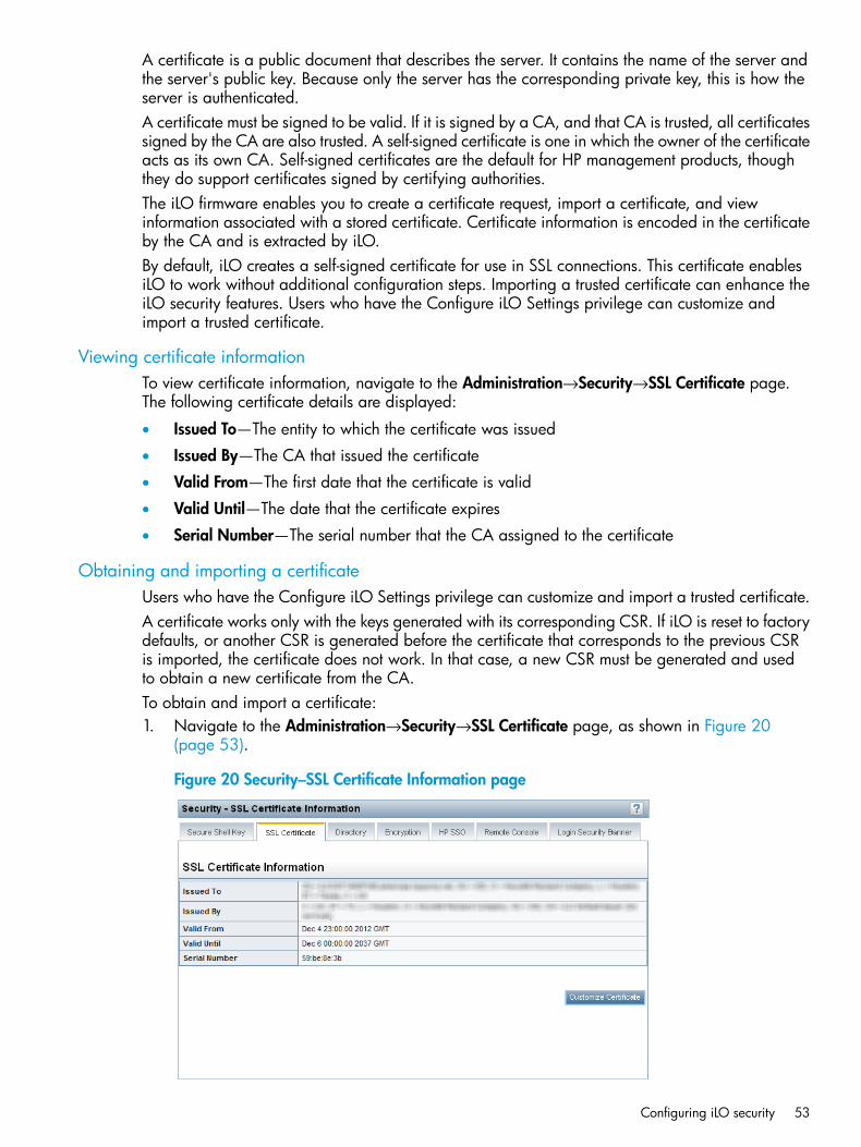
A certificate is a public document that describes the server. It contains the name of the server andthe server's public key. Because only the server has the corresponding private key, this is how theserver is authenticated.A certificate must be signed to be valid. If it is signed by a CA, and that CA is trusted, all certificatessigned by the CA are also trusted. A self-signed certificate is one in which the owner of the certificateacts as its own CA. Self-signed certificates are the default for HP management products, thoughthey do support certificates signed by certifying authorities.The iLO firmware enables you to create a certificate request, import a certificate, and viewinformation associated with a stored certificate. Certificate information is encoded in the certificateby the CA and is extracted by iLO.By default, iLO creates a self-signed certificate for use in SSL connections. This certificate enablesiLO to work without additional configuration steps. Importing a trusted certificate can enhance theiLO security features. Users who have the Configure iLO Settings privilege can customize andimport a trusted certificate.
Viewing certificate informationTo view certificate information, navigate to the Administration→Security→SSL Certificate page.The following certificate details are displayed:
• Issued To—The entity to which the certificate was issued
• Issued By—The CA that issued the certificate
• Valid From—The first date that the certificate is valid
• Valid Until—The date that the certificate expires
• Serial Number—The serial number that the CA assigned to the certificate
Obtaining and importing a certificateUsers who have the Configure iLO Settings privilege can customize and import a trusted certificate.A certificate works only with the keys generated with its corresponding CSR. If iLO is reset to factorydefaults, or another CSR is generated before the certificate that corresponds to the previous CSRis imported, the certificate does not work. In that case, a new CSR must be generated and usedto obtain a new certificate from the CA.To obtain and import a certificate:1. Navigate to the Administration→Security→SSL Certificate page, as shown in Figure 20
(page 53).
Figure 20 Security–SSL Certificate Information page
Configuring iLO security 53
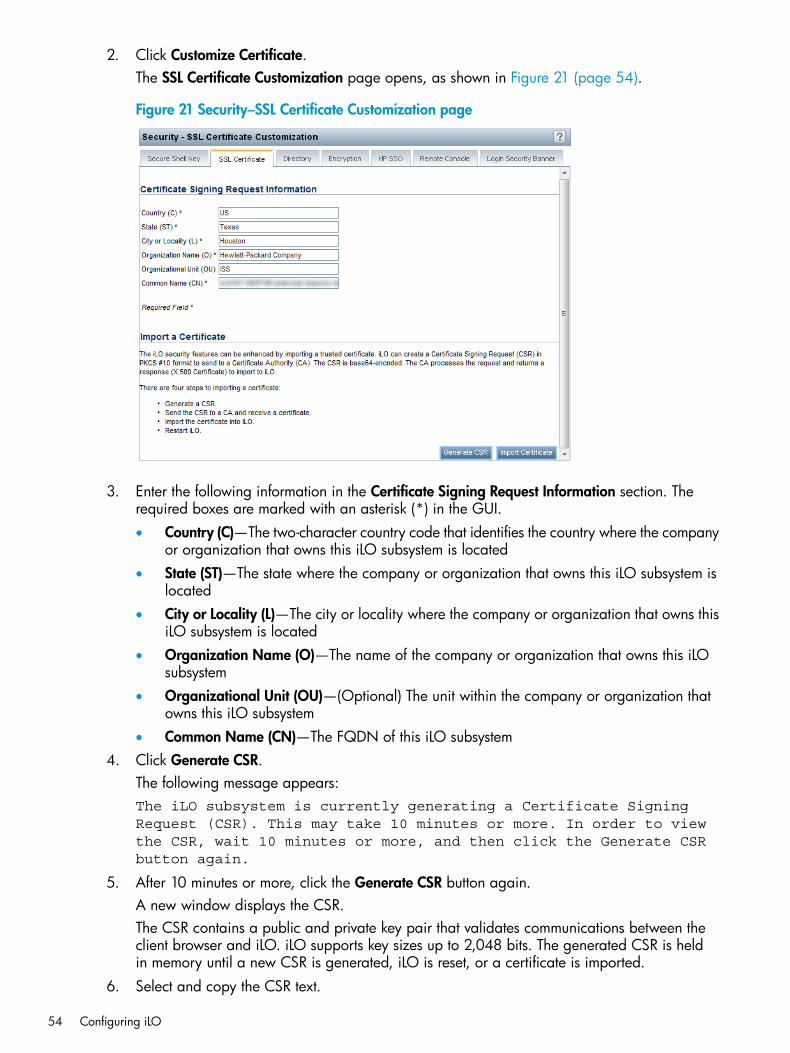
2. Click Customize Certificate.The SSL Certificate Customization page opens, as shown in Figure 21 (page 54).
Figure 21 Security–SSL Certificate Customization page
3. Enter the following information in the Certificate Signing Request Information section. Therequired boxes are marked with an asterisk (*) in the GUI.• Country (C)—The two-character country code that identifies the country where the company
or organization that owns this iLO subsystem is located• State (ST)—The state where the company or organization that owns this iLO subsystem is
located• City or Locality (L)—The city or locality where the company or organization that owns this
iLO subsystem is located• Organization Name (O)—The name of the company or organization that owns this iLO
subsystem• Organizational Unit (OU)—(Optional) The unit within the company or organization that
owns this iLO subsystem• Common Name (CN)—The FQDN of this iLO subsystem
4. Click Generate CSR.The following message appears:The iLO subsystem is currently generating a Certificate SigningRequest (CSR). This may take 10 minutes or more. In order to viewthe CSR, wait 10 minutes or more, and then click the Generate CSRbutton again.
5. After 10 minutes or more, click the Generate CSR button again.A new window displays the CSR.The CSR contains a public and private key pair that validates communications between theclient browser and iLO. iLO supports key sizes up to 2,048 bits. The generated CSR is heldin memory until a new CSR is generated, iLO is reset, or a certificate is imported.
6. Select and copy the CSR text.
54 Configuring iLO
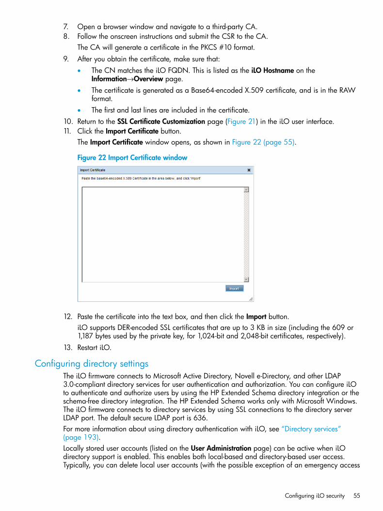
7. Open a browser window and navigate to a third-party CA.8. Follow the onscreen instructions and submit the CSR to the CA.
The CA will generate a certificate in the PKCS #10 format.9. After you obtain the certificate, make sure that:
• The CN matches the iLO FQDN. This is listed as the iLO Hostname on theInformation→Overview page.
• The certificate is generated as a Base64-encoded X.509 certificate, and is in the RAWformat.
• The first and last lines are included in the certificate.10. Return to the SSL Certificate Customization page (Figure 21) in the iLO user interface.11. Click the Import Certificate button.
The Import Certificate window opens, as shown in Figure 22 (page 55).
Figure 22 Import Certificate window
12. Paste the certificate into the text box, and then click the Import button.iLO supports DER-encoded SSL certificates that are up to 3 KB in size (including the 609 or1,187 bytes used by the private key, for 1,024-bit and 2,048-bit certificates, respectively).
13. Restart iLO.
Configuring directory settingsThe iLO firmware connects to Microsoft Active Directory, Novell e-Directory, and other LDAP3.0-compliant directory services for user authentication and authorization. You can configure iLOto authenticate and authorize users by using the HP Extended Schema directory integration or theschema-free directory integration. The HP Extended Schema works only with Microsoft Windows.The iLO firmware connects to directory services by using SSL connections to the directory serverLDAP port. The default secure LDAP port is 636.For more information about using directory authentication with iLO, see “Directory services”(page 193).Locally stored user accounts (listed on the User Administration page) can be active when iLOdirectory support is enabled. This enables both local-based and directory-based user access.Typically, you can delete local user accounts (with the possible exception of an emergency access
Configuring iLO security 55
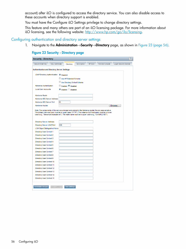
account) after iLO is configured to access the directory service. You can also disable access tothese accounts when directory support is enabled.You must have the Configure iLO Settings privilege to change directory settings.This feature and many others are part of an iLO licensing package. For more information aboutiLO licensing, see the following website: http://www.hp.com/go/ilo/licensing.
Configuring authentication and directory server settings1. Navigate to the Administration→Security→Directory page, as shown in Figure 23 (page 56).
Figure 23 Security - Directory page
56 Configuring iLO
2. Configure the following options:• LDAP Directory Authentication—Enables or disables directory authentication. If directory
authentication is enabled and configured correctly, users can log in by using directorycredentials.Choose from the following options:
◦ Disabled—User credentials are not validated using the directory.
◦ Use HP Extended Schema—Selects directory authentication and authorization byusing directory objects created with the HP Extended Schema. Select this optionwhen the directory has been extended with the HP Extended Schema.
◦ Use Directory Default Schema—Selects directory authentication and authorizationby using user accounts in the directory. Select this option when the directory is notextended with the HP Extended Schema. User accounts and group memberships areused to authenticate and authorize users. After you enter and save the directorynetwork information, click Administer Groups, and then enter one or more validdirectory DNs and privileges to grant users access to iLO.
• Kerberos Authentication—Enables Kerberos login. If Kerberos login is enabled andconfigured correctly, the HP Zero Sign In button appears on the login page.
• Local User Accounts—Enables or disables local user account access.
Enabled—A user can log in by using locally stored user credentials. HP recommendsenabling this option and configuring a user account with administrator privileges.This account can be used if iLO cannot communicate with the directory server.
◦
◦ Disabled—User access is limited to valid directory credentials.
Access through local user accounts is enabled when directory support is disabled or aniLO license is revoked. You cannot disable local user access when you are logged inthrough a local user account.
• Kerberos Realm—The name of the Kerberos realm in which the iLO processor is operating.This string can be up to 128 characters. A realm name is usually the DNS name convertedto uppercase. Realm names are case sensitive.
• Kerberos KDC Server Address—The IP address or DNS name of the KDC server. Thisstring can be up to 128 characters. Each realm must have at least one KDC that containsan authentication server and a ticket grant server. These servers can be combined.
• Kerberos KDC Server Port—The TCP or UDP port number on which the KDC is listening.The default KDC port is 88.
• Kerberos Keytab—A binary file that contains pairs of service principal names andencrypted passwords. In the Windows environment, the keytab file is generated by thektpass utility. Click Browse (Internet Explorer or Firefox) or Choose File (Chrome), andthen follow the onscreen instructions to select a file.
IMPORTANT: The components of the service principal name stored in the Kerberoskeytab file are case sensitive. The primary (service type) must be in uppercase letters, forexample, (HTTP). The instance (iLO host name) must be in lowercase letters, for example,iloexample.example.net. The realm name must be in uppercase, for example,EXAMPLE.NET.
3. Enter the directory server settings.iLO directory server settings enable you to identify the directory server address and LDAP port.• Directory Server Address—Specifies the network DNS name or IP address of the directory
server. The directory server address can be up to 127 characters.
Configuring iLO security 57
IMPORTANT: HP recommends using DNS round-robin when you are defining thedirectory server.
• Directory Server LDAP Port—Specifies the port number for the secure LDAP service on theserver. The default value is 636. You can specify a different value if your directory serviceis configured to use a different port.
• LOMObject Distinguished Name—Specifies where this iLO instance is listed in the directorytree (for example, cn=iLO Mail Server,ou=Management Devices,o=hp). Thisoption is available when Use HP Extended Schema is selected.User search contexts are not applied to the LOM object DN when iLO accesses thedirectory server.
• Directory User Contexts—These boxes enable you to specify common directory subcontextsso that users do not need to enter their full DNs at login. Directory user contexts can beup to 128 characters.You can identify the objects listed in a directory by using unique DNs. However, DNscan be long, and users might not know their DNs or might have accounts in differentdirectory contexts. iLO attempts to contact the directory service by DN, and then appliesthe search contexts in order until successful.
◦ Example 1—If you enter the search context ou=engineering,o=hp, you can login as user instead of logging in as cn=user,ou=engineering,o=hp.
◦ Example 2—If a system is managed by Information Management, Services, andTraining, search contexts such as the following enable users in any of theseorganizations to log in by using their common names:Directory User Context 1:ou=IM,o=hpDirectory User Context 2:ou=Services,o=hpDirectory User Context 3:ou=Training,o=hp
If a user exists in both the IM organizational unit and the Training organizationalunit, login is first attempted as cn=user,ou=IM,o=hp.
◦ Example 3 (Active Directory only)—Microsoft Active Directory allows an alternateuser credential format. A user can log in as [email protected], in whichcase a search context of @domain.example.com allows the user to log in as user.Only a successful login attempt can test search contexts in this format.
4. Click Apply Settings.5. To test the communication between the directory server and iLO, click Test Settings.
For more information, see “Running directory tests” (page 58).6. Optional: Click Administer Groups to navigate to the User Administration page.
For information about group administration, see “Administering directory groups” (page 37).
Running directory testsDirectory tests enable you to validate the configured directory settings. The directory test resultsare reset when directory settings are saved, or when the directory tests are started.To validate the configured directory settings:
58 Configuring iLO
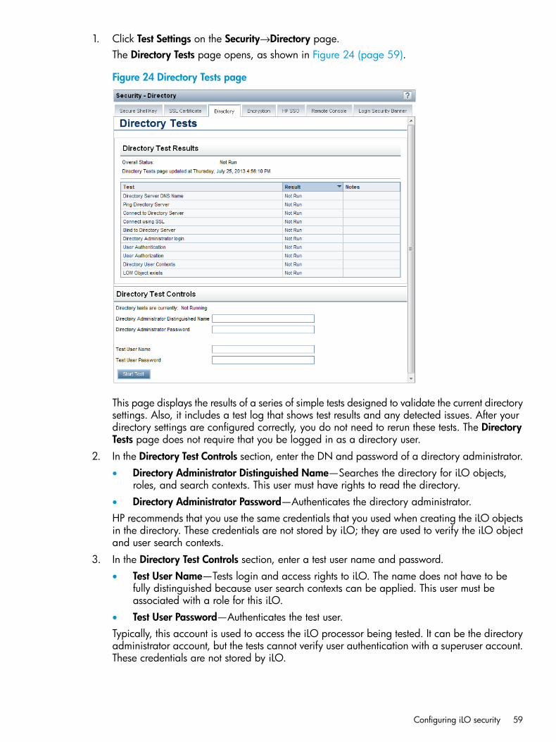
1. Click Test Settings on the Security→Directory page.The Directory Tests page opens, as shown in Figure 24 (page 59).
Figure 24 Directory Tests page
This page displays the results of a series of simple tests designed to validate the current directorysettings. Also, it includes a test log that shows test results and any detected issues. After yourdirectory settings are configured correctly, you do not need to rerun these tests. The DirectoryTests page does not require that you be logged in as a directory user.
2. In the Directory Test Controls section, enter the DN and password of a directory administrator.• Directory Administrator Distinguished Name—Searches the directory for iLO objects,
roles, and search contexts. This user must have rights to read the directory.• Directory Administrator Password—Authenticates the directory administrator.HP recommends that you use the same credentials that you used when creating the iLO objectsin the directory. These credentials are not stored by iLO; they are used to verify the iLO objectand user search contexts.
3. In the Directory Test Controls section, enter a test user name and password.• Test User Name—Tests login and access rights to iLO. The name does not have to be
fully distinguished because user search contexts can be applied. This user must beassociated with a role for this iLO.
• Test User Password—Authenticates the test user.Typically, this account is used to access the iLO processor being tested. It can be the directoryadministrator account, but the tests cannot verify user authentication with a superuser account.These credentials are not stored by iLO.
Configuring iLO security 59
4. Click Start Test.Several tests begin in the background, starting with a network ping of the directory user byestablishing an SSL connection to the server and evaluating user privileges.
While the tests are running, the page refreshes periodically. You can stop the tests or manuallyrefresh the page at any time.
Viewing directory test resultsThe Directory Test Results section shows the directory test status with the date and time of the lastupdate.
• Overall Status—Summarizes the results of the tests.
Not Run—No tests were run.◦◦ Inconclusive—No results were reported.
◦ Passed—No failures were reported.
◦ Problem Detected—A problem was reported.
◦ Failed—A specific subtest failed. Check the onscreen log to identify the problem.
◦ Warning—One or more of the directory tests reported a Warning status.
• Test—The name of each test.Table 5 (page 60) provides details about each directory test.
Table 5 Directory tests
DescriptionTest
If the directory server is defined in FQDN format (directory.company.com), iLOresolves the name from FQDN format to IP format, and queries the configured DNSserver.
Directory Server DNSName
If the test is successful, iLO obtained an IP address for the configured directory server. IfiLO cannot obtain an IP address for the directory server, this test and all subsequent testsfail.If the directory server is configured with an IP address, iLO skips this test.If a failure occurs:1. Verify that the DNS server configured in iLO is correct.2. Verify that the directory server FQDN is correct.3. As a troubleshooting tool, use an IP address instead of the FQDN.4. If the problem persists, check the DNS server records and network routing.
iLO initiates a ping to the configured directory server.Ping Directory ServerThe test is successful if iLO receives the ping response; it is unsuccessful if the directoryserver does not reply to iLO.If the test fails, iLO will continue with the subsequent tests.If a failure occurs:1. Check to see if a firewall is active on the directory server.2. Check for network routing issues.
iLO attempts to negotiate an LDAP connection with the directory server.Connect to DirectoryServer If the test is successful, iLO was able to initiate the connection.
If the test fails, iLO was not able to initiate an LDAP connection with the specified directoryserver. Subsequent tests will stop.If a failure occurs:
60 Configuring iLO
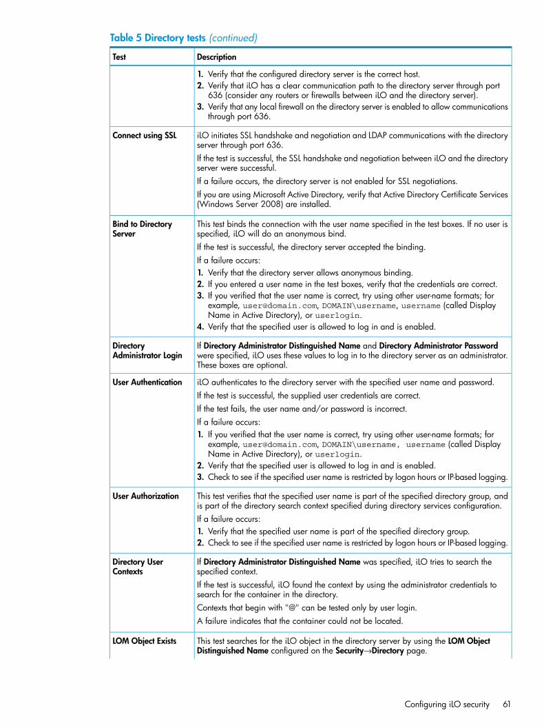
Table 5 Directory tests (continued)
DescriptionTest
1. Verify that the configured directory server is the correct host.2. Verify that iLO has a clear communication path to the directory server through port
636 (consider any routers or firewalls between iLO and the directory server).3. Verify that any local firewall on the directory server is enabled to allow communications
through port 636.
iLO initiates SSL handshake and negotiation and LDAP communications with the directoryserver through port 636.
Connect using SSL
If the test is successful, the SSL handshake and negotiation between iLO and the directoryserver were successful.If a failure occurs, the directory server is not enabled for SSL negotiations.If you are using Microsoft Active Directory, verify that Active Directory Certificate Services(Windows Server 2008) are installed.
This test binds the connection with the user name specified in the test boxes. If no user isspecified, iLO will do an anonymous bind.
Bind to DirectoryServer
If the test is successful, the directory server accepted the binding.If a failure occurs:1. Verify that the directory server allows anonymous binding.2. If you entered a user name in the test boxes, verify that the credentials are correct.3. If you verified that the user name is correct, try using other user-name formats; for
example, [email protected], DOMAIN\username, username (called DisplayName in Active Directory), or userlogin.
4. Verify that the specified user is allowed to log in and is enabled.
If Directory Administrator Distinguished Name and Directory Administrator Passwordwere specified, iLO uses these values to log in to the directory server as an administrator.These boxes are optional.
DirectoryAdministrator Login
iLO authenticates to the directory server with the specified user name and password.User AuthenticationIf the test is successful, the supplied user credentials are correct.If the test fails, the user name and/or password is incorrect.If a failure occurs:1. If you verified that the user name is correct, try using other user-name formats; for
example, [email protected], DOMAIN\username, username (called DisplayName in Active Directory), or userlogin.
2. Verify that the specified user is allowed to log in and is enabled.3. Check to see if the specified user name is restricted by logon hours or IP-based logging.
This test verifies that the specified user name is part of the specified directory group, andis part of the directory search context specified during directory services configuration.
User Authorization
If a failure occurs:1. Verify that the specified user name is part of the specified directory group.2. Check to see if the specified user name is restricted by logon hours or IP-based logging.
If Directory Administrator Distinguished Name was specified, iLO tries to search thespecified context.
Directory UserContexts
If the test is successful, iLO found the context by using the administrator credentials tosearch for the container in the directory.Contexts that begin with "@" can be tested only by user login.A failure indicates that the container could not be located.
This test searches for the iLO object in the directory server by using the LOM ObjectDistinguished Name configured on the Security→Directory page.
LOM Object Exists
Configuring iLO security 61
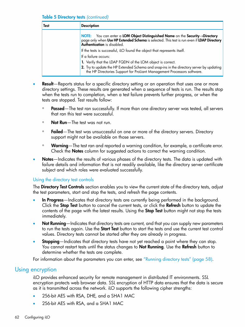
Table 5 Directory tests (continued)
DescriptionTest
NOTE: You can enter a LOM Object Distinguished Name on the Security→Directorypage only when Use HP Extended Schema is selected. This test is run even if LDAP DirectoryAuthentication is disabled.If the tests is successful, iLO found the object that represents itself.If a failure occurs:1. Verify that the LDAP FQDN of the LOM object is correct.2. Try to update the HP Extended Schema and snap-ins in the directory server by updating
the HP Directories Support for ProLiant Management Processors software.
• Result—Reports status for a specific directory setting or an operation that uses one or moredirectory settings. These results are generated when a sequence of tests is run. The results stopwhen the tests run to completion, when a test failure prevents further progress, or when thetests are stopped. Test results follow:
◦ Passed—The test ran successfully. If more than one directory server was tested, all serversthat ran this test were successful.
◦ Not Run—The test was not run.
◦ Failed—The test was unsuccessful on one or more of the directory servers. Directorysupport might not be available on those servers.
◦ Warning—The test ran and reported a warning condition, for example, a certificate error.Check the Notes column for suggested actions to correct the warning condition.
• Notes—Indicates the results of various phases of the directory tests. The data is updated withfailure details and information that is not readily available, like the directory server certificatesubject and which roles were evaluated successfully.
Using the directory test controlsThe Directory Test Controls section enables you to view the current state of the directory tests, adjustthe test parameters, start and stop the tests, and refresh the page contents.
• In Progress—Indicates that directory tests are currently being performed in the background.Click the Stop Test button to cancel the current tests, or click the Refresh button to update thecontents of the page with the latest results. Using the Stop Test button might not stop the testsimmediately.
• Not Running—Indicates that directory tests are current, and that you can supply new parametersto run the tests again. Use the Start Test button to start the tests and use the current test controlvalues. Directory tests cannot be started after they are already in progress.
• Stopping—Indicates that directory tests have not yet reached a point where they can stop.You cannot restart tests until the status changes to Not Running. Use the Refresh button todetermine whether the tests are complete.
For information about the parameters you can enter, see “Running directory tests” (page 58).
Using encryptioniLO provides enhanced security for remote management in distributed IT environments. SSLencryption protects web browser data. SSL encryption of HTTP data ensures that the data is secureas it is transmitted across the network. iLO supports the following cipher strengths:
• 256-bit AES with RSA, DHE, and a SHA1 MAC
• 256-bit AES with RSA, and a SHA1 MAC
62 Configuring iLO
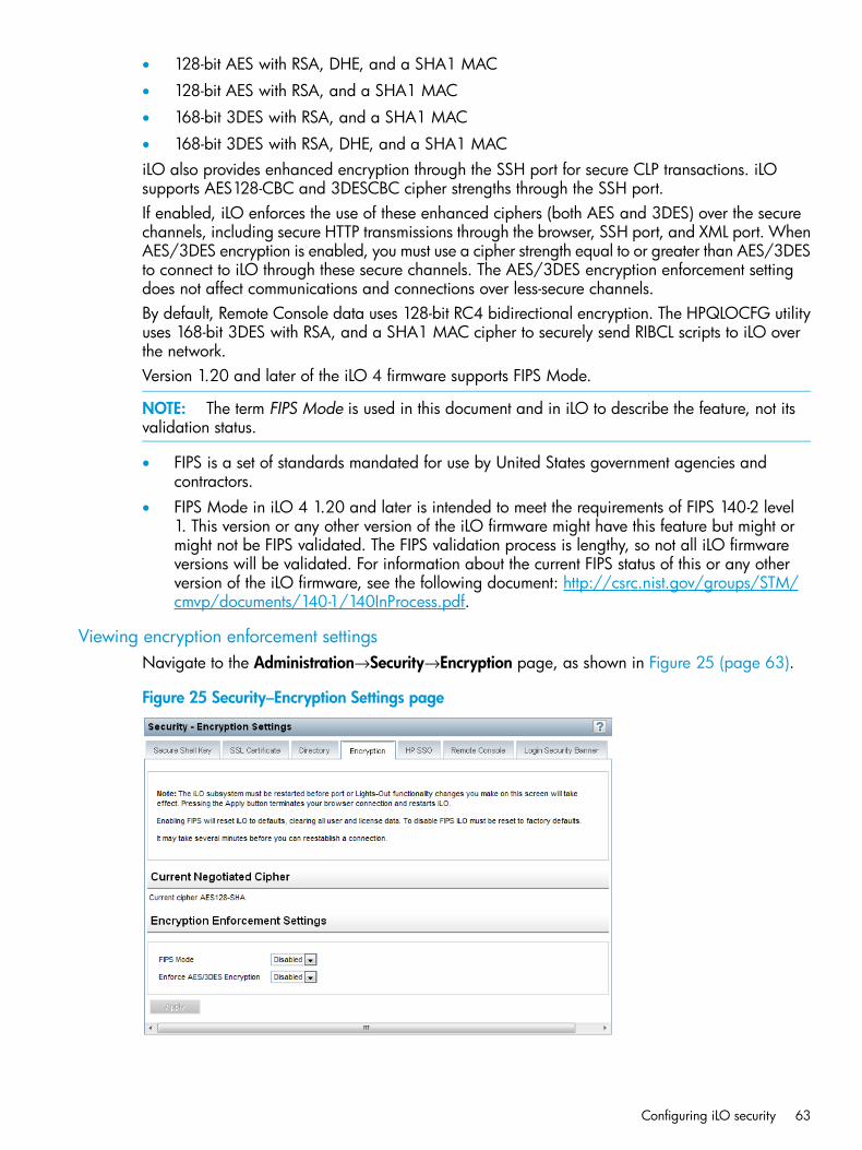
• 128-bit AES with RSA, DHE, and a SHA1 MAC
• 128-bit AES with RSA, and a SHA1 MAC
• 168-bit 3DES with RSA, and a SHA1 MAC
• 168-bit 3DES with RSA, DHE, and a SHA1 MACiLO also provides enhanced encryption through the SSH port for secure CLP transactions. iLOsupports AES128-CBC and 3DESCBC cipher strengths through the SSH port.If enabled, iLO enforces the use of these enhanced ciphers (both AES and 3DES) over the securechannels, including secure HTTP transmissions through the browser, SSH port, and XML port. WhenAES/3DES encryption is enabled, you must use a cipher strength equal to or greater than AES/3DESto connect to iLO through these secure channels. The AES/3DES encryption enforcement settingdoes not affect communications and connections over less-secure channels.By default, Remote Console data uses 128-bit RC4 bidirectional encryption. The HPQLOCFG utilityuses 168-bit 3DES with RSA, and a SHA1 MAC cipher to securely send RIBCL scripts to iLO overthe network.Version 1.20 and later of the iLO 4 firmware supports FIPS Mode.
NOTE: The term FIPS Mode is used in this document and in iLO to describe the feature, not itsvalidation status.
• FIPS is a set of standards mandated for use by United States government agencies andcontractors.
• FIPS Mode in iLO 4 1.20 and later is intended to meet the requirements of FIPS 140-2 level1. This version or any other version of the iLO firmware might have this feature but might ormight not be FIPS validated. The FIPS validation process is lengthy, so not all iLO firmwareversions will be validated. For information about the current FIPS status of this or any otherversion of the iLO firmware, see the following document: http://csrc.nist.gov/groups/STM/cmvp/documents/140-1/140InProcess.pdf.
Viewing encryption enforcement settingsNavigate to the Administration→Security→Encryption page, as shown in Figure 25 (page 63).
Figure 25 Security–Encryption Settings page
Configuring iLO security 63
The Encryption Settings page displays the current encryption settings for iLO.
• Current Negotiated Cipher—The cipher in use for the current browser session. After you login to iLO through the browser, the browser and iLO negotiate a cipher setting to use duringthe session.
• Encryption Enforcement Settings—The current encryption settings for iLO:
FIPS Mode—Indicates whether FIPS Mode is enabled or disabled for this iLO system.◦◦ Enforce AES/3DES Encryption—Indicates whether AES/3DES encryption is enforced for
this iLO.When enabled, iLO accepts only those connections through the browser and SSH interfacethat meet the minimum cipher strength. A cipher strength of at least AES or 3DES mustbe used to connect to iLO when this setting is enabled.
Modifying the AES/DES encryption settingYou must have the Configure iLO Settings privilege to change the encryption settings.To modify the AES/DES encryption setting:1. Navigate to the Administration→Security→Encryption page, as shown in Figure 25 (page 63).2. Change the Enforce AES/3DES Encryption setting to Enabled or Disabled.3. Click Apply to end your browser connection and restart iLO.
It might take several minutes before you can re-establish a connection.When changing the Enforce AES/3DES Encryption setting to Enabled, close all open browsersafter clicking Apply. Any browsers that remain open might continue to use a non-AES/3DEScipher.
Connecting to iLO by using AES or 3DES encryptionAfter you enable the Enforce AES/3DES Encryption setting, iLO requires that you connect throughsecure channels (web browser, SSH connection, or XML channel) by using a cipher strength of atleast AES or 3DES.
• Web browser—You must configure the browser with a cipher strength of at least AES or 3DES.If the browser is not using AES or 3DES ciphers, iLO displays an error message. The error textvaries depending on the installed browser.Different browsers use different methods for selecting a negotiated cipher. For more information,see your browser documentation. You must log out of iLO through the current browser beforechanging the browser cipher setting. Any changes made to the browser cipher setting whileyou are logged in to iLO might enable the browser to continue using a non-AES/3DES cipher.
• SSH connection—For instructions on setting the cipher strength, see the SSH utilitydocumentation.
• XML channel—HPQLOCFG uses a secure 3DES cipher by default. For example, HPQLOCFGdisplays the following cipher strength in the XML output:Connecting to Server...Negotiated cipher: 168-bit Triple DES with RSA and a SHA1 MAC
Enabling FIPS ModeYou must have the Configure iLO Settings privilege to change the encryption settings.To enable FIPS Mode for iLO:1. Optional: Capture the current iLO configuration by using HPONCFG.
For more information, see the HP iLO 4 Scripting and Command Line Guide.
64 Configuring iLO
2. Verify that a trusted certificate is installed.Using iLO in FIPS Mode with the default self-signed certificate is not FIPS compliant. Forinstructions, see “Obtaining and importing a certificate” (page 53).
IMPORTANT: Some interfaces to iLO, such as supported versions of IPMI and SNMP, arenot FIPS compliant and cannot be made FIPS compliant. For information about the iLO firmwareversions that are FIPS validated, see the following document: http://csrc.nist.gov/groups/STM/cmvp/documents/140-1/140-1val.zip
3. Power off the server.4. Navigate to the Administration→Security→Encryption page, as shown in Figure 25 (page 63).5. Set FIPS Mode to Enabled.
CAUTION: Enabling FIPS Mode resets iLO to the factory default settings, and clears all userand license data.
6. Click Apply.iLO reboots in FIPS Mode. Wait at least 90 seconds before attempting to re-establish aconnection.
7. Optional: Restore the iLO configuration by using HPONCFG.For more information, see the HP iLO 4 Scripting and Command Line Guide.
TIP: You can use the Login Security Banner feature to notify iLO users that a system is using FIPSMode. For more information, see “Configuring the Login Security Banner” (page 71).
Disabling FIPS ModeIf you want to disable FIPS Mode for iLO (for example, if a server is decommissioned), you mustuse iLO RBSU or XML configuration and control scripts to reset iLO to the factory default settings.For instructions, see “Resetting iLO to the factory default settings by using iLO RBSU” (page 262) orthe HP iLO 4 Scripting and Command Line Guide.When you disable FIPS Mode, all potentially sensitive data is erased, including all logs and settings.
Configuring iLO for HP SSOHP SSO enables you to browse directly from an HP SSO-compliant application (such as HP SIM)to iLO, bypassing an intermediate login step. To use SSO, you must have a supported version ofan HP SSO-compliant application, you might need iLO 4 1.20 or later, and you must configurethe iLO processor to trust the SSO-compliant application.This feature and many others are part of an iLO licensing package. For more information aboutiLO licensing, see the following website: http://www.hp.com/go/ilo/licensing.Some HP SSO-compliant applications automatically import trust certificates when they connect toiLO. For applications that do not do this automatically, use the HP SSO page to configure the SSOsettings through the iLO web interface. You must have the Configure iLO Settings privilege tochange these settings.
Configuring iLO security 65
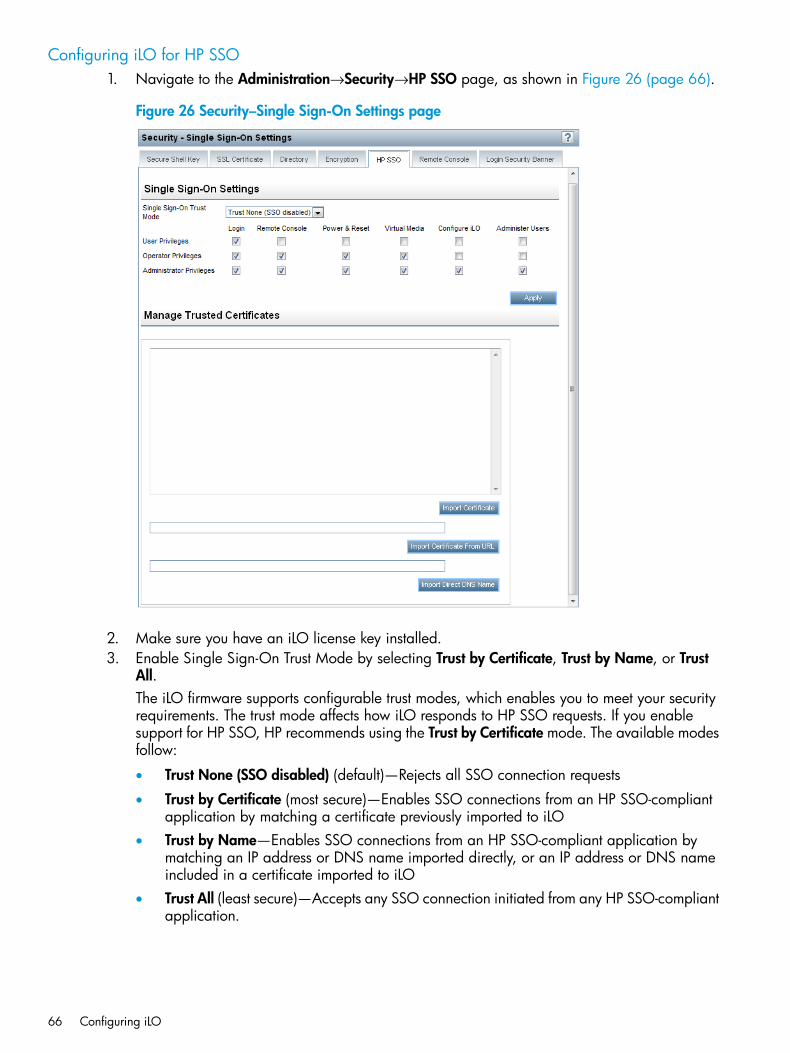
Configuring iLO for HP SSO1. Navigate to the Administration→Security→HP SSO page, as shown in Figure 26 (page 66).
Figure 26 Security–Single Sign-On Settings page
2. Make sure you have an iLO license key installed.3. Enable Single Sign-On Trust Mode by selecting Trust by Certificate, Trust by Name, or Trust
All.The iLO firmware supports configurable trust modes, which enables you to meet your securityrequirements. The trust mode affects how iLO responds to HP SSO requests. If you enablesupport for HP SSO, HP recommends using the Trust by Certificate mode. The available modesfollow:
• Trust None (SSO disabled) (default)—Rejects all SSO connection requests
• Trust by Certificate (most secure)—Enables SSO connections from an HP SSO-compliantapplication by matching a certificate previously imported to iLO
• Trust by Name—Enables SSO connections from an HP SSO-compliant application bymatching an IP address or DNS name imported directly, or an IP address or DNS nameincluded in a certificate imported to iLO
• Trust All (least secure)—Accepts any SSO connection initiated from any HP SSO-compliantapplication.
66 Configuring iLO
4. Configure iLO privileges for each role in the Single Sign-On Settings section.When you log in to an HP SSO-compliant application, you are authorized based on your HPSSO-compliant application role assignment. The role assignment is passed to iLO when SSOis attempted. For more information about each privilege, see “Administering users” (page 33).SSO attempts to receive only the privileges assigned in this section. iLO directory settings donot apply. Default privilege assignments are as follows:
• User—Login only
• Operator—Login, Remote Console, Power and Reset, and Virtual Media
• Administrator—Login, Remote Console, Power and Reset, Virtual Media, Configure iLO,and Administer Users
5. Click Apply to save the SSO settings.6. If you selected Trust by Certificate or Trust by Name, add the trusted certificate or DNS name
to iLO.For more information about adding certificates and DNS names, see “Adding trustedcertificates” (page 67).The certificate repository can hold five typical certificates. However, if typical certificates arenot issued, certificate sizes might vary. When all of the allocated storage is used, no moreimports are accepted.
7. After you configure SSO in iLO, log in to an HP SSO-compliant application and browse toiLO. For example, log in to HP SIM, navigate to the System page for the iLO processor, andthen click the iLO link in the More Information section.
NOTE: Although a system might be registered as a trusted server, SSO might be refusedbecause of the current trust mode or certificate status. For example, if an HP SIM server nameis registered, and the trust mode is Trust by Certificate, but the certificate is not imported, SSOis not allowed from that server. Likewise, if an HP SIM server certificate is imported, but thecertificate has expired, SSO is not allowed from that server. The list of trusted servers is notused when SSO is disabled. iLO does not enforce SSO server certificate revocation.
Adding trusted certificatesiLO users who have the Configure iLO Settings privilege can install trusted certificates or add directDNS names.The Base64-encoded X.509 certificate data resembles the following:-----BEGIN CERTIFICATE-----
. . . several lines of encoded data . . .-----END CERTIFICATE-----
To add trusted HP SSO records by using the iLO web interface:1. Navigate to the Administration→Security→HP SSO page, as shown in Figure 26 (page 66).2. Use one of the following methods to add a trusted certificate:
• To directly import a trusted certificate, copy the Base64-encoded certificate X.509 data,paste it into the text box above the Import Certificate button, and then click the button.
• To indirectly import a trusted certificate, type the DNS name or IP address in the text boxabove the Import Certificate from URL button, and then click the button. iLO contacts theHP SSO-compliant application over the network, retrieves the certificate, and then savesit.
• To import the direct DNS name, enter the DNS name in the text box above the ImportDirect DNS Name button, and then click the button.
Configuring iLO security 67
For information about how to extract an HP SIM certificate, see “Extracting the HP SIM servercertificate” (page 68).For information about how to extract certificates from other HP SSO-compliant applications, seeyour HP SSO-compliant application documentation.
Extracting the HP SIM server certificateYou can use the following methods to extract HP SIM certificates.
NOTE: iLO 4 1.20 or later might be required to install the larger certificates used with recentversions of HP SIM.
• Enter one of the following links in a web browser:
For HP SIM versions earlier than 7.0:http://<HP SIM name or network address>:280/GetCertificate
◦
https://<HP SIM name or network address>:50000/GetCertificate
◦ For HP SIM 7.0 or later:http://<HP SIM name or networkaddress>:280/GetCertificate?certtype=sso
https://<HP SIM name or networkaddress>:50000/GetCertificate?certtype=sso
NOTE: All request parameters are case-sensitive. If you capitalize the lowercasecerttype parameter, the parameter will not be read, and HP SIM will return the defaultHP SIM server certificate instead of a trust certificate.
• Export the certificate from HP SIM:
For HP SIM versions earlier than 7.0:Select Options→Security→Certificates→Server Certificate.
◦
◦ For HP SIM 7.0 or later:Select Options→Security→HP Systems Insight Manager Server Certificate, and then clickExport.
• Use the HP SIM command-line tools. For example, using the alias tomcat for the HP SIMcertificate, enter mxcert -l tomcat.
For more information, see the HP SIM documentation.
Viewing trusted certificatesThe Manage Trusted Certificates table on the Single Sign-On Settings page displays the status ofthe trusted certificates configured to use SSO with the current iLO management processor.
• Status—The status of the record (if any are installed).
68 Configuring iLO
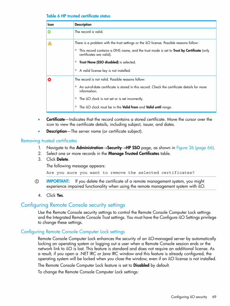
Table 6 HP trusted certificate status
DescriptionIcon
The record is valid.
There is a problem with the trust settings or the iLO license. Possible reasons follow:
◦ This record contains a DNS name, and the trust mode is set to Trust by Certificate (onlycertificates are valid).
◦ Trust None (SSO disabled) is selected.
◦ A valid license key is not installed.
The record is not valid. Possible reasons follow:
◦ An out-of-date certificate is stored in this record. Check the certificate details for moreinformation.
◦ The iLO clock is not set or is set incorrectly.
◦ The iLO clock must be in the Valid from and Valid until range.
• Certificate—Indicates that the record contains a stored certificate. Move the cursor over theicon to view the certificate details, including subject, issuer, and dates.
• Description—The server name (or certificate subject).
Removing trusted certificates1. Navigate to the Administration→Security→HP SSO page, as shown in Figure 26 (page 66).2. Select one or more records in the Manage Trusted Certificates table.3. Click Delete.
The following message appears:Are you sure you want to remove the selected certificates?
IMPORTANT: If you delete the certificate of a remote management system, you mightexperience impaired functionality when using the remote management system with iLO.
4. Click Yes.
Configuring Remote Console security settingsUse the Remote Console security settings to control the Remote Console Computer Lock settingsand the Integrated Remote Console Trust settings. You must have the Configure iLO Settings privilegeto change these settings.
Configuring Remote Console Computer Lock settingsRemote Console Computer Lock enhances the security of an iLO-managed server by automaticallylocking an operating system or logging out a user when a Remote Console session ends or thenetwork link to iLO is lost. This feature is standard and does not require an additional license. Asa result, if you open a .NET IRC or Java IRC window and this feature is already configured, theoperating system will be locked when you close the window, even if an iLO license is not installed.The Remote Console Computer Lock feature is set to Disabled by default.To change the Remote Console Computer Lock settings:
Configuring iLO security 69
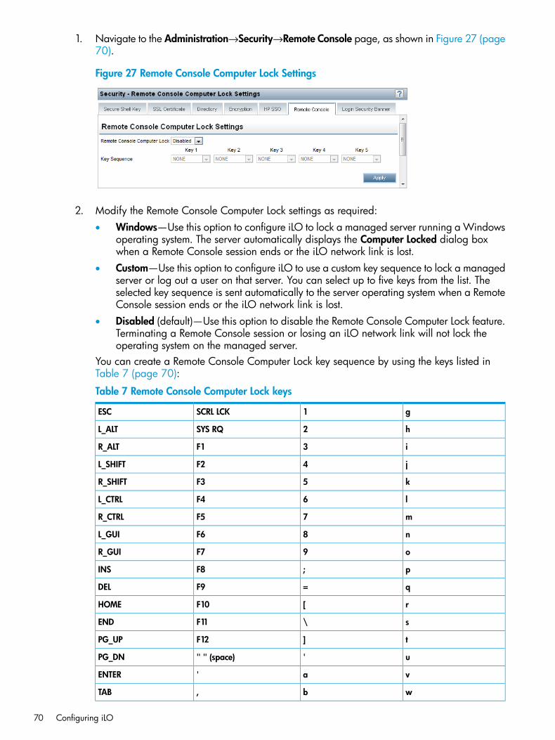
1. Navigate to the Administration→Security→Remote Console page, as shown in Figure 27 (page70).
Figure 27 Remote Console Computer Lock Settings
2. Modify the Remote Console Computer Lock settings as required:• Windows—Use this option to configure iLO to lock a managed server running a Windows
operating system. The server automatically displays the Computer Locked dialog boxwhen a Remote Console session ends or the iLO network link is lost.
• Custom—Use this option to configure iLO to use a custom key sequence to lock a managedserver or log out a user on that server. You can select up to five keys from the list. Theselected key sequence is sent automatically to the server operating system when a RemoteConsole session ends or the iLO network link is lost.
• Disabled (default)—Use this option to disable the Remote Console Computer Lock feature.Terminating a Remote Console session or losing an iLO network link will not lock theoperating system on the managed server.
You can create a Remote Console Computer Lock key sequence by using the keys listed inTable 7 (page 70):
Table 7 Remote Console Computer Lock keys
g1SCRL LCKESC
h2SYS RQL_ALT
i3F1R_ALT
j4F2L_SHIFT
k5F3R_SHIFT
l6F4L_CTRL
m7F5R_CTRL
n8F6L_GUI
o9F7R_GUI
p;F8INS
q=F9DEL
r[F10HOME
s\F11END
t]F12PG_UP
u'" " (space)PG_DN
va'ENTER
wb,TAB
70 Configuring iLO
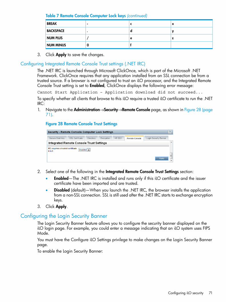
Table 7 Remote Console Computer Lock keys (continued)
xc-BREAK
yd.BACKSPACE
ze/NUM PLUS
f0NUM MINUS
3. Click Apply to save the changes.
Configuring Integrated Remote Console Trust settings (.NET IRC)The .NET IRC is launched through Microsoft ClickOnce, which is part of the Microsoft .NETFramework. ClickOnce requires that any application installed from an SSL connection be from atrusted source. If a browser is not configured to trust an iLO processor, and the Integrated RemoteConsole Trust setting is set to Enabled, ClickOnce displays the following error message:Cannot Start Application – Application download did not succeed...
To specify whether all clients that browse to this iLO require a trusted iLO certificate to run the .NETIRC:1. Navigate to the Administration→Security→Remote Console page, as shown in Figure 28 (page
71).
Figure 28 Remote Console Trust Settings
2. Select one of the following in the Integrated Remote Console Trust Settings section:• Enabled—The .NET IRC is installed and runs only if this iLO certificate and the issuer
certificate have been imported and are trusted.• Disabled (default)—When you launch the .NET IRC, the browser installs the application
from a non-SSL connection. SSL is still used after the .NET IRC starts to exchange encryptionkeys.
3. Click Apply.
Configuring the Login Security BannerThe Login Security Banner feature allows you to configure the security banner displayed on theiLO login page. For example, you could enter a message indicating that an iLO system uses FIPSMode.You must have the Configure iLO Settings privilege to make changes on the Login Security Bannerpage.To enable the Login Security Banner:
Configuring iLO security 71
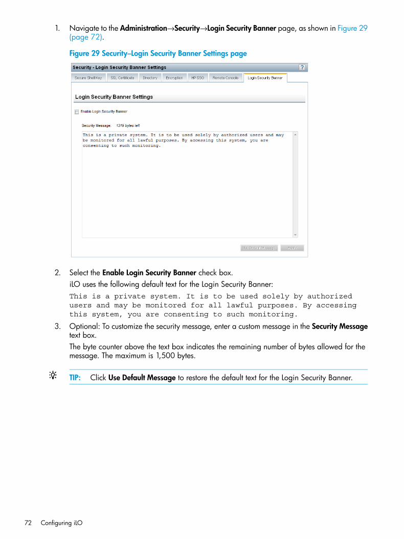
1. Navigate to the Administration→Security→Login Security Banner page, as shown in Figure 29(page 72).
Figure 29 Security–Login Security Banner Settings page
2. Select the Enable Login Security Banner check box.iLO uses the following default text for the Login Security Banner:This is a private system. It is to be used solely by authorizedusers and may be monitored for all lawful purposes. By accessingthis system, you are consenting to such monitoring.
3. Optional: To customize the security message, enter a custom message in the Security Messagetext box.The byte counter above the text box indicates the remaining number of bytes allowed for themessage. The maximum is 1,500 bytes.
TIP: Click Use Default Message to restore the default text for the Login Security Banner.
72 Configuring iLO
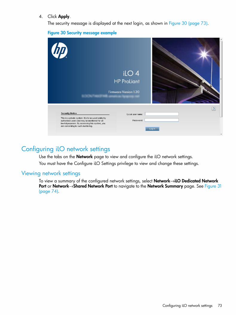
4. Click Apply.The security message is displayed at the next login, as shown in Figure 30 (page 73).
Figure 30 Security message example
Configuring iLO network settingsUse the tabs on the Network page to view and configure the iLO network settings.You must have the Configure iLO Settings privilege to view and change these settings.
Viewing network settingsTo view a summary of the configured network settings, select Network→iLO Dedicated NetworkPort or Network→Shared Network Port to navigate to the Network Summary page. See Figure 31(page 74).
Configuring iLO network settings 73
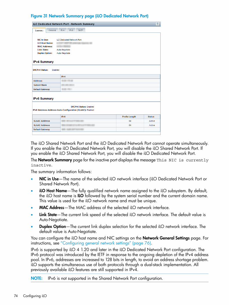
Figure 31 Network Summary page (iLO Dedicated Network Port)
The iLO Shared Network Port and the iLO Dedicated Network Port cannot operate simultaneously.If you enable the iLO Dedicated Network Port, you will disable the iLO Shared Network Port. Ifyou enable the iLO Shared Network Port, you will disable the iLO Dedicated Network Port.The Network Summary page for the inactive port displays the message This NIC is currentlyinactive.The summary information follows:
• NIC in Use—The name of the selected iLO network interface (iLO Dedicated Network Port orShared Network Port).
• iLO Host Name—The fully qualified network name assigned to the iLO subsystem. By default,the iLO host name is ILO followed by the system serial number and the current domain name.This value is used for the iLO network name and must be unique.
• MAC Address—The MAC address of the selected iLO network interface.
• Link State—The current link speed of the selected iLO network interface. The default value isAuto-Negotiate.
• Duplex Option—The current link duplex selection for the selected iLO network interface. Thedefault value is Auto-Negotiate.
You can configure the iLO host name and NIC settings on the Network General Settings page. Forinstructions, see “Configuring general network settings” (page 76).IPv6 is supported by iLO 4 1.20 and later in the iLO Dedicated Network Port configuration. TheIPv6 protocol was introduced by the IETF in response to the ongoing depletion of the IPv4 addresspool. In IPv6, addresses are increased to 128 bits in length, to avoid an address shortage problem.iLO supports the simultaneous use of both protocols through a dual-stack implementation. Allpreviously available iLO features are still supported in IPv4.
NOTE: IPv6 is not supported in the Shared Network Port configuration.
74 Configuring iLO
The following features support the use of IPv6:
• IPv6 Static Address Assignment
• IPv6 SLAAC Address Assignment
• IPv6 Static Route Assignment
• iLO Remote Console
• OA Single Sign-On
• Web Server
• SSH Server
• NTP Client
• DDNS Client
• DHCPv6 Client
• HP SSO
• RIBCL
• SNMPIPv6 support for the iLO scripting interfaces requires the following versions of the iLO utilities:
• HPQLOCFG 1.0 or later
• HP Lights-Out XML Scripting Sample bundle 4.2.0 or later
• HPONCFG 4.2.0 or later
• LOCFG.PL 4.2.0 or later
• HPLOMIG 4.2.0 or laterThe IPv4 Summary section displays the following information:
• DHCPv4 Status—Indicates whether DHCP is enabled for IPv4.
• Address—The IPv4 address currently in use. If the value is 0.0.0.0, the IPv4 address is notconfigured.
• Subnet Mask—The subnet mask of the IPv4 address currently in use. If the value is 0.0.0.0,no address is configured.
• Default Gateway—The default gateway address in use for the IPv4 protocol. If the value is0.0.0.0, the gateway is not configured.
The IPv6 Summary section displays the following information:
• DHCPv6 Status—Indicates whether DHCP is enabled for IPv6. The following values are possible:
Enabled—Stateless and Stateful DHCPv6 are enabled.◦◦ Enabled (Stateless)—Only Stateless DHCPv6 is enabled.
◦ Disabled—DHCPv6 is disabled.
• IPv6 Stateless Address Auto-Configuration (SLAAC)—Indicates whether SLAAC is enabled forIPv6. When SLAAC is disabled, the SLAAC link-local address for iLO is still configured becauseit is required.
• Address list—This table shows the currently configured IPv6 addresses for iLO. It provides thefollowing information:
◦ Source—Indicates whether the address is a static or SLAAC address.
◦ IPv6—The IPv6 address.
Configuring iLO network settings 75
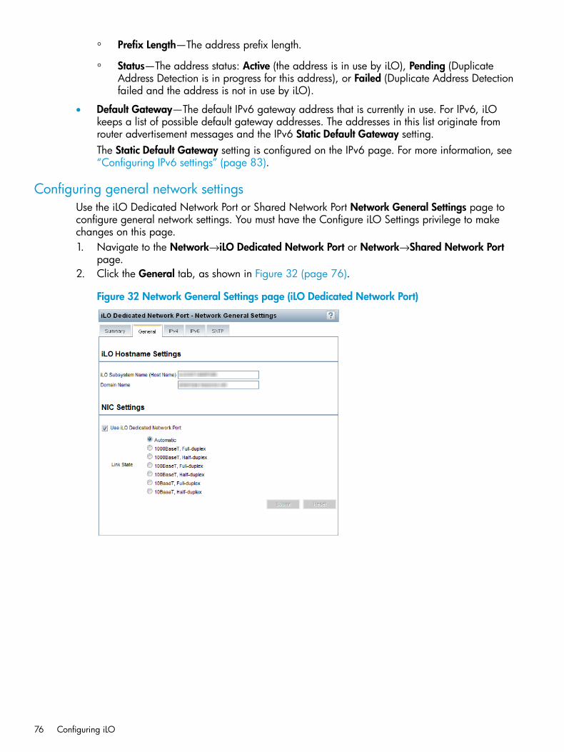
◦ Prefix Length—The address prefix length.
◦ Status—The address status: Active (the address is in use by iLO), Pending (DuplicateAddress Detection is in progress for this address), or Failed (Duplicate Address Detectionfailed and the address is not in use by iLO).
• Default Gateway—The default IPv6 gateway address that is currently in use. For IPv6, iLOkeeps a list of possible default gateway addresses. The addresses in this list originate fromrouter advertisement messages and the IPv6 Static Default Gateway setting.The Static Default Gateway setting is configured on the IPv6 page. For more information, see“Configuring IPv6 settings” (page 83).
Configuring general network settingsUse the iLO Dedicated Network Port or Shared Network Port Network General Settings page toconfigure general network settings. You must have the Configure iLO Settings privilege to makechanges on this page.1. Navigate to the Network→iLO Dedicated Network Port or Network→Shared Network Port
page.2. Click the General tab, as shown in Figure 32 (page 76).
Figure 32 Network General Settings page (iLO Dedicated Network Port)
76 Configuring iLO
3. Enter the following information in the iLO Hostname Settings section:• iLO Subsystem Name (Host Name)—The DNS name of the iLO subsystem (for example,
ilo instead of ilo.example.com). This name can be used only if DHCP and DNSare configured to connect to the iLO subsystem name instead of the IP address.iLO subsystem-name limitations follow:
◦ Name service limitations—The subsystem name is used as part of the DNS name.DNS allows alphanumeric characters and hyphens.–
– Name service limitations also apply to the Domain Name.
◦ Namespace issues—To avoid these issues:– Do not use the underscore character.
– Limit subsystem names to 15 characters.
– Verify that you can ping iLO by IP address and by DNS/WINS name.
– Verify that NSLOOKUP resolves the iLO network address correctly and that nonamespace conflicts exist.
– If you are using both DNS and WINS, verify that they resolve the iLO networkaddress correctly.
– Flush the DNS name if you make any namespace changes.
• Domain Name—The iLO domain name. If DHCP is not used, enter a domain name.4. Enter the following information in the NIC Settings section:
• Select the Use iLO Dedicated Network Port, Use Shared Network Port – LOM, or UseShared Network Port – Flexible LOM check box to enable or disable the iLO DedicatedNetwork Port or Shared Network Port.
◦ iLO Dedicated Network Port—Uses a NIC with a jack on the back of the server. TheNIC handles iLO traffic only.
◦ Shared Network Port – LOM—Uses a NIC that is built into the server. The NIC handlesserver network traffic and can, if iLO is configured to do so, handle iLO traffic at thesame time.
◦ Shared Network Port – Flexible LOM—Uses an optional NIC that plugs into a specialslot on the server. The NIC handles server network traffic and can, if iLO is configuredto do so, handle iLO traffic at the same time. Not all servers support a FlexibleLOM.For the list of servers that support the Shared Network Port – FlexibleLOM option,see “FlexibleLOM support” (page 271).
On systems that have more than one Shared Network Port option, select the check box,and then select the LOM or FlexibleLOM option.For more information about using the Shared Network Port, see “Using the iLO SharedNetwork Port” (page 78).
• Select a Link State (iLO Dedicated Network Port only).The link setting controls the speed and duplex settings of the iLO network transceiver.
NOTE: This setting is not available on blade servers.
Configuring iLO network settings 77
The available settings follow:
◦ Automatic (default)—Enables iLO to negotiate the highest supported link speed andduplex settings when connected to the network
◦ 1000BaseT, Full-duplex—Forces a 1 Gb connection that uses full duplex (notsupported for BL c-Class servers)
◦ 1000BaseT, Half-duplex—Forces a 1 Gb connection that uses half duplex (notsupported for BL c-Class servers)
◦ 100BaseT, Full-duplex—Forces a 100 Mb connection using full duplex
◦ 100BaseT, Half-duplex—Forces a 100 Mb connection using half duplex
◦ 10BaseT, Full-duplex—Forces a 10 Mb connection using full duplex
◦ 10BaseT, Half-duplex—Forces a 10 Mb connection using half duplex
If the Shared Network Port is enabled, you cannot modify the link state or duplex option.In Shared Network Port configurations, link settings must be managed in the operatingsystem.
• Select or clear the Enable VLAN check box to enable or disable VLAN (Shared NetworkPort only).When the Shared Network Port is active and VLAN is enabled, the iLO Shared NetworkPort becomes part of a VLAN. All network devices with different VLAN tags will appearto be on separate LANs, even if they are physically connected to the same LAN.
• If you enabled VLAN, enter a VLAN Tag (Shared Network Port only). All network devicesthat you want to communicate with each other must have the same VLAN tag. The VLANtag can be any number between 1 and 4094.
5. Click Submit to save the changes.6. If you are finished configuring the iLO network settings on the General, IPv4, IPv6, and SNTP
tabs, click Reset to restart iLO.It might take several minutes before you can re-establish a connection.
Using the iLO Shared Network PortThe iLO Shared Network Port feature enables you to choose between the Shared Network PortLOM, FlexibleLOM, and the iLO Dedicated Network Port for server management. When you enablethe iLO Shared Network Port, regular network traffic and iLO network traffic pass through theselected Shared Network Port NIC. The iLO Shared Network Port does not incur an iLO performancepenalty. Peak iLO traffic is less than 2 Mb/s on a NIC capable of a speed of 1 GB/s or 10 GB/s.iLO traffic volume is low unless the Virtual Media or Remote Console feature is in use.On servers that do not have an iLO Dedicated Network Port, the standard hardware configurationprovides iLO network connectivity only through the iLO Shared Network Port connection. The iLOfirmware automatically defaults to the Shared Network Port.The iLO Shared Network Port uses the network port labeled NIC 1 on the rear panel of the serverwhen Use Shared Network Port – LOM is selected, and uses the network port labeled 1 on theFlexibleLOM adapter if Use Shared Network Port – Flexible LOM is selected. NIC numbering inthe operating system can be different from system numbering.When using the iLO Shared Network Port, observe the following:
• The iLO Shared Network Port is supported on all nonblade servers.
• For the list of servers that support the iLO Shared Network Port FlexibleLOM feature, see“FlexibleLOM support” (page 271).
78 Configuring iLO
• You can use the iLO Shared Network Port and the iLO Dedicated Network Port only for iLOserver management.
• The iLO Shared Network Port is not an availability feature. Its purpose is to allow managednetwork port consolidation.
• Due to server auxiliary-power budget limitations, some 1Gb/s copper network adapters usedfor iLO Shared Network Port functionality might only run at 10/100 speed when the serveris powered off. To avoid this issue, HP recommends configuring the switch the iLO SharedNetwork Port is connected to for autonegotiation.If you want to configure the iLO switch for a speed of 1Gb/s, be aware that some copperiLO Shared Network Port adapters might lose connectivity when the server is powered off.Connectivity will return when the server is powered back on.
• The iLO Shared Network Port and iLO Dedicated Network Port cannot operate simultaneously.If you enable the iLO Dedicated Network Port, you will disable the iLO Shared Network Port.If you enable the iLO Shared Network Port, you will disable the iLO Dedicated Network Port.
• Disabling the iLO Shared Network Port does not completely disable the system NIC—networktraffic still passes through the NIC. When the iLO Shared Network Port is disabled, any trafficgoing to or originating from iLO will not pass through the iLO Shared Network Port becausethat port is no longer shared with iLO.
• Using the iLO Shared Network Port can create a single failure point. If the port fails or isunplugged, both the host and iLO become unavailable to the network.
Enabling the iLO Shared Network Port featureThe iLO Shared Network Port feature is disabled by default on servers that are shipped with aDedicated iLO Management NIC. You can enable it by using the following methods:
• iLO RBSU—For more information, see “Enabling the iLO Shared Network Port feature throughiLO RBSU” (page 79).
• iLO web interface—For more information, see “Enabling the iLO Shared Network Port featurethrough the iLO web interface” (page 80).
• XML configuration and control scripts—For more information, see the HP iLO 4 Scripting andCommand Line Guide.
• SMASH CLP—For more information, see the HP iLO 4 Scripting and Command Line Guide.
Enabling the iLO Shared Network Port feature through iLO RBSU
1. Connect the Shared Network Port LOM or FlexibleLOM port 1 to a LAN.2. Press F8 during POST to enter iLO RBSU.3. Select Network→NIC and TCP/IP, and then press Enter.4. On the Network Configuration menu, press the spacebar to toggle the Network Interface
Adapter setting to Shared Network Port – LOM or Shared Network Port – FlexibleLOM, asshown in Figure 33 (page 80).
NOTE: The Shared Network Port option is available only on supported servers.
Configuring iLO network settings 79
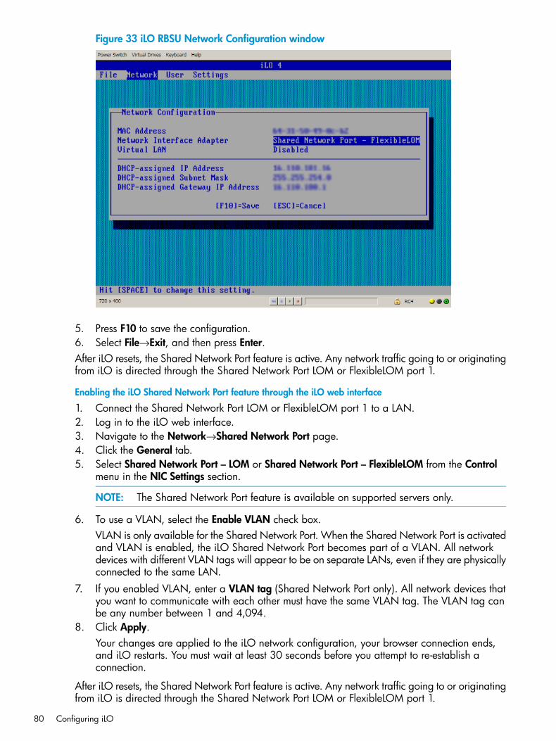
Figure 33 iLO RBSU Network Configuration window
5. Press F10 to save the configuration.6. Select File→Exit, and then press Enter.After iLO resets, the Shared Network Port feature is active. Any network traffic going to or originatingfrom iLO is directed through the Shared Network Port LOM or FlexibleLOM port 1.
Enabling the iLO Shared Network Port feature through the iLO web interface
1. Connect the Shared Network Port LOM or FlexibleLOM port 1 to a LAN.2. Log in to the iLO web interface.3. Navigate to the Network→Shared Network Port page.4. Click the General tab.5. Select Shared Network Port – LOM or Shared Network Port – FlexibleLOM from the Control
menu in the NIC Settings section.
NOTE: The Shared Network Port feature is available on supported servers only.
6. To use a VLAN, select the Enable VLAN check box.VLAN is only available for the Shared Network Port. When the Shared Network Port is activatedand VLAN is enabled, the iLO Shared Network Port becomes part of a VLAN. All networkdevices with different VLAN tags will appear to be on separate LANs, even if they are physicallyconnected to the same LAN.
7. If you enabled VLAN, enter a VLAN tag (Shared Network Port only). All network devices thatyou want to communicate with each other must have the same VLAN tag. The VLAN tag canbe any number between 1 and 4,094.
8. Click Apply.Your changes are applied to the iLO network configuration, your browser connection ends,and iLO restarts. You must wait at least 30 seconds before you attempt to re-establish aconnection.
After iLO resets, the Shared Network Port feature is active. Any network traffic going to or originatingfrom iLO is directed through the Shared Network Port LOM or FlexibleLOM port 1.
80 Configuring iLO
Re-enabling the iLO Dedicated Network PortOnly the Shared Network Port or the iLO Dedicated Network Port is active for server management.They cannot be enabled at the same time. If you enabled the Shared Network Port, use one of thefollowing methods if you want to re-enable the iLO Dedicated Network Port:
• iLO RBSU—For more information, see “Enabling the iLO Dedicated Network Port through iLORBSU” (page 81).
• iLO web interface—For more information, see “Enabling the iLO Dedicated Network Portthrough the web interface” (page 81).
• XML scripting—For more information, see the HP iLO 4 Scripting and Command Line Guide.
Enabling the iLO Dedicated Network Port through iLO RBSU
1. Connect the iLO Dedicated Network Port to a LAN from which the server is managed.2. Reboot the server.3. Press F8 during POST to enter iLO RBSU.4. Select Network→NIC and TCP/IP, and then press Enter.5. On the Network Configuration menu, press the spacebar to toggle the Network Interface
Adapter setting to On.6. Press F10 to save the configuration.7. Select File→Exit, and then press Enter.
After iLO resets, the iLO Dedicated Network Port is active.
Enabling the iLO Dedicated Network Port through the web interface
1. Connect the iLO Dedicated Network Port to a LAN from which the server is managed.2. Log in to the iLO web interface.3. Navigate to the Network→iLO Dedicated Network Port page.4. Click the General tab.5. Select the Use iLO Dedicated Network Port check box.6. Select a Link State.
For more information, see “Configuring general network settings” (page 76).7. Click Apply.
Your changes are applied to the iLO network configuration, your browser connection ends,and iLO restarts. You must wait at least 30 seconds before you attempt to re-establish aconnection.
Configuring IPv4 settingsUse the iLO Dedicated Network Port or Shared Network Port IPv4 Settings page to configure IPv4settings for iLO. You must have the Configure iLO Settings privilege to make changes on this page.1. Navigate to the Network→iLO Dedicated Network Port or Network→Shared Network Port
page.2. Click the IPv4 tab, as shown in Figure 34 (page 82).
Configuring iLO network settings 81
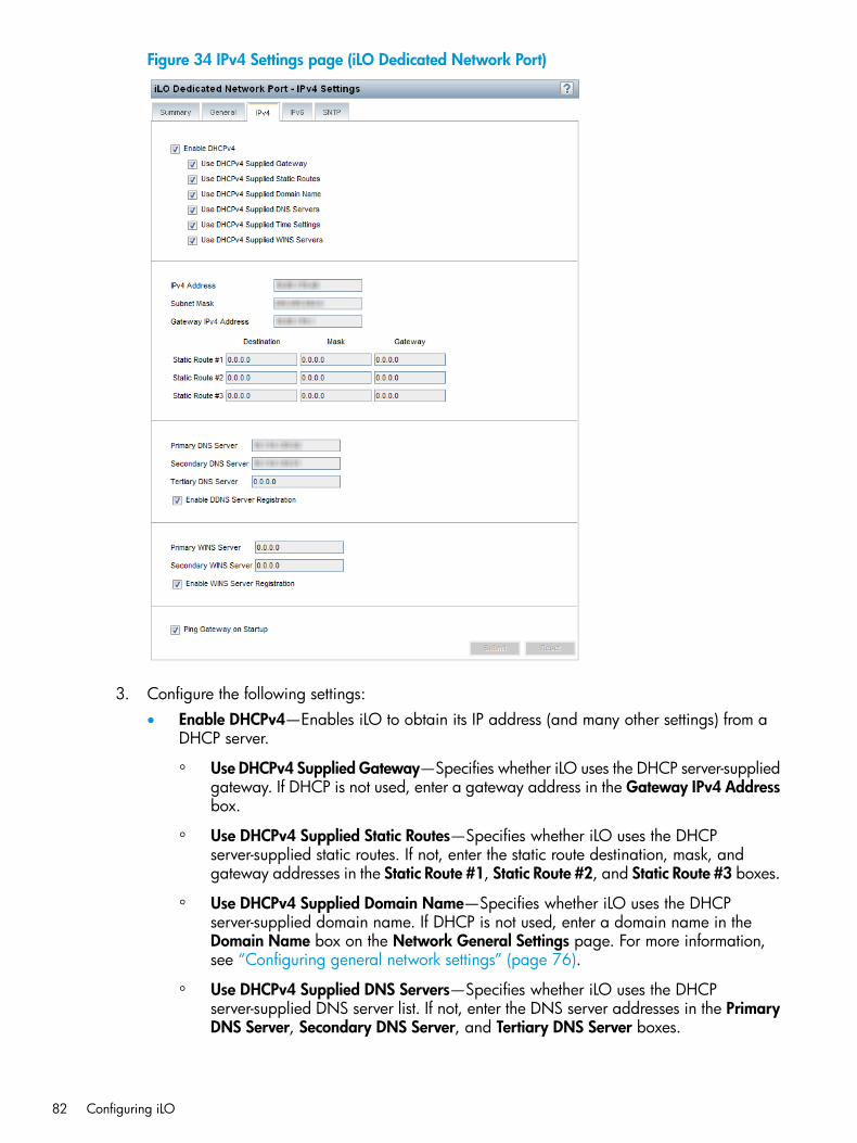
Figure 34 IPv4 Settings page (iLO Dedicated Network Port)
3. Configure the following settings:• Enable DHCPv4—Enables iLO to obtain its IP address (and many other settings) from a
DHCP server.
◦ Use DHCPv4 Supplied Gateway—Specifies whether iLO uses the DHCP server-suppliedgateway. If DHCP is not used, enter a gateway address in the Gateway IPv4 Addressbox.
◦ Use DHCPv4 Supplied Static Routes—Specifies whether iLO uses the DHCPserver-supplied static routes. If not, enter the static route destination, mask, andgateway addresses in the Static Route #1, Static Route #2, and Static Route #3 boxes.
◦ Use DHCPv4 Supplied Domain Name—Specifies whether iLO uses the DHCPserver-supplied domain name. If DHCP is not used, enter a domain name in theDomain Name box on the Network General Settings page. For more information,see “Configuring general network settings” (page 76).
◦ Use DHCPv4 Supplied DNS Servers—Specifies whether iLO uses the DHCPserver-supplied DNS server list. If not, enter the DNS server addresses in the PrimaryDNS Server, Secondary DNS Server, and Tertiary DNS Server boxes.
82 Configuring iLO
◦ Use DHCPv4 Supplied Time Settings—Specifies whether iLO uses the DHCPv4-suppliedNTP service locations.
◦ Use DHCPv4 Supplied WINS Servers—Specifies whether iLO uses the DHCPserver-supplied WINS server list. If not, enter the WINS server addresses in thePrimary WINS Server and Secondary WINS Server boxes.
• IPv4 Address—The iLO IP address. If DHCP is used, the iLO IP address is suppliedautomatically. If DHCP is not used, enter a static IP address.
• Subnet Mask—The subnet mask of the iLO IP network. If DHCP is used, the subnet maskis supplied automatically. If DHCP is not used, enter a subnet mask for the network.
• Gateway IPv4 Address—The iLO gateway IP address. If DHCP is used, the iLO gatewayIP address is supplied automatically. If DHCP is not used, enter the iLO gateway IP address.
• Static Route #1, Static Route #2, and Static Route #3—The iLO static route destination,mask, and gateway addresses. If Use DHCPv4 Supplied Static Routes is used, these valuesare supplied automatically. If not, enter the static route values.
• DNS server information—Enter the following information:
Primary DNS Server—If Use DHCPv4 Supplied DNS Servers is enabled, this value issupplied automatically. If not, enter the Primary DNS Server address.
◦
◦ Secondary DNS Server—If Use DHCPv4 Supplied DNS Servers is enabled, this valueis supplied automatically. If not, enter the Secondary DNS Server address.
◦ Tertiary DNS Server—If Use DHCPv4 Supplied DNS Servers is enabled, this value issupplied automatically. If not, enter the Tertiary DNS Server address.
◦ Enable DDNS Server Registration—Select or clear this check box to specify whetheriLO registers its IPv4 address and name with a DNS server.
• WINS server information—Enter the following information:
Primary WINS Server—If Use DHCPv4 Supplied WINS Servers is enabled, this valueis supplied automatically. If not, enter the Primary WINS Server address.
◦
◦ Secondary WINS Server—If Use DHCPv4 Supplied WINS Servers is enabled, thisvalue is supplied automatically. If not, enter the Secondary WINS Server address.
◦ Enable WINS Server Registration—Specifies whether iLO registers its name with aWINS server.
• Ping Gateway on Startup—Causes iLO to send four ICMP echo request packets to thegateway when iLO initializes. This ensures that the ARP cache entry for iLO is up-to-dateon the router responsible for routing packets to and from iLO.
4. Click Submit to save the changes you made on the IPv4 Settings page.5. If you are finished configuring the iLO network settings on the General, IPv4, IPv6, and SNTP
tabs, click Reset to restart iLO.It might take several minutes before you can re-establish a connection.
Configuring IPv6 settingsUse the iLO Dedicated Network Port IPv6 Settings page to configure IPv6 settings for iLO. Youmust have the Configure iLO Settings privilege to make changes on this page.
Configuring iLO network settings 83
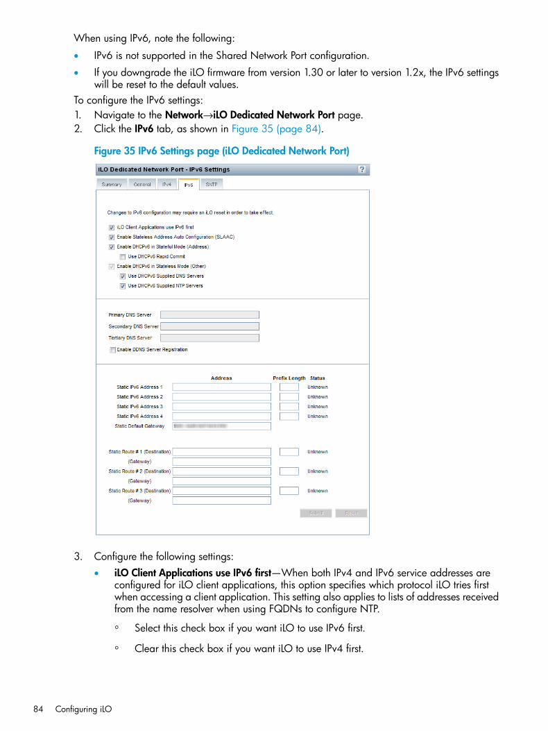
When using IPv6, note the following:
• IPv6 is not supported in the Shared Network Port configuration.
• If you downgrade the iLO firmware from version 1.30 or later to version 1.2x, the IPv6 settingswill be reset to the default values.
To configure the IPv6 settings:1. Navigate to the Network→iLO Dedicated Network Port page.2. Click the IPv6 tab, as shown in Figure 35 (page 84).
Figure 35 IPv6 Settings page (iLO Dedicated Network Port)
3. Configure the following settings:• iLO Client Applications use IPv6 first—When both IPv4 and IPv6 service addresses are
configured for iLO client applications, this option specifies which protocol iLO tries firstwhen accessing a client application. This setting also applies to lists of addresses receivedfrom the name resolver when using FQDNs to configure NTP.
◦ Select this check box if you want iLO to use IPv6 first.
◦ Clear this check box if you want iLO to use IPv4 first.
84 Configuring iLO
If communication fails using the first protocol, iLO automatically tries the second protocol.
• Enable Stateless Address Auto Configuration (SLAAC)—Select this check box to enableiLO to create IPv6 addresses for itself from router advertisement messages.
NOTE: iLO will create its own link-local address even when this option is not selected.
• Enable DHCPv6 in Stateful Mode (Address)—Select this check box to allow iLO to requestand configure IPv6 addresses provided by a DHCPv6 server.
◦ Use DHCPv6 Rapid Commit—Select this check box to instruct iLO to use the RapidCommit messaging mode with the DHCPv6 server. This mode reduces DHCPv6network traffic, but might cause problems if it is used in networks where more thanone DHCPv6 server can respond and provide addresses.
• Enable DHCPv6 in Stateless Mode (Other)—Select this check box to enable iLO to requestsettings for NTP and DNS service location from the DHCPv6 server.
◦ Use DHCPv6 Supplied DNS Servers—Select this check box to use IPv6 addressesprovided by the DHCPv6 server for DNS server locations. This setting can be enabledin addition to the IPv4 DNS server location options.
◦ Use DHCPv6 Supplied NTP Servers—Select this check box to use IPv6 addressesprovided by the DHCPv6 server for NTP server locations. This setting can be enabledin addition to the IPv4 NTP server location options.
NOTE: When Enable DHCPv6 in Stateful Mode (Address) is selected, Enable DHCPv6in Stateless Mode (Other) is always selected by default, because it is implicit in the DHCPv6Stateful messages required between iLO and the DHCPv6 server.
• Primary DNS Server, Secondary DNS Server, and Tertiary DNS Server—Enter the IPv6addresses for the DNS service.When DNS server locations are configured in both IPv4 and IPv6, both sources are used,with preference given according to the iLO Client Applications use IPv6 first configurationoption, primary sources, then secondary, and then tertiary.
• Enable DDNS Server Registration—Specify whether iLO registers its IPv6 address andname with a DNS server.
• Static IPv6 Address 1, Static IPv6 Address 2, Static IPv6 Address 3, and Static IPv6 Address4—Enter up to four static IPv6 addresses and prefix lengths for iLO. Do not enter link-localaddresses.
• Static Default Gateway—Enter a default IPv6 gateway address for cases in which norouter advertisement messages are present in the network.
• Static Route #1, Static Route #2, and Static Route #3—Enter static IPv6 route destinationprefix and gateway address pairs. You must specify the prefix length for the destination.Link-local addresses are not allowed for the destination, but are allowed for the gateway.
4. Click Submit to save the changes you made on the IPv6 Settings page.5. If you are finished configuring the iLO network settings on the General, IPv4, IPv6, and SNTP
tabs, click Reset to restart iLO.It might take several minutes before you can re-establish a connection.
Configuring iLO network settings 85
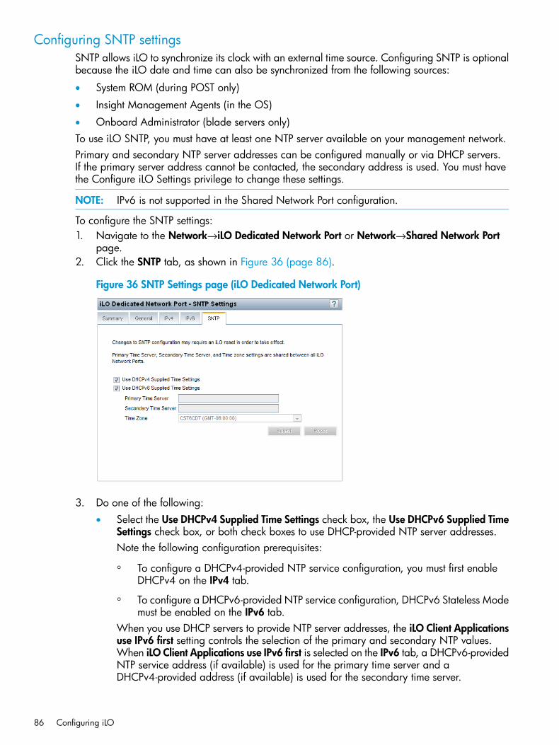
Configuring SNTP settingsSNTP allows iLO to synchronize its clock with an external time source. Configuring SNTP is optionalbecause the iLO date and time can also be synchronized from the following sources:
• System ROM (during POST only)
• Insight Management Agents (in the OS)
• Onboard Administrator (blade servers only)To use iLO SNTP, you must have at least one NTP server available on your management network.Primary and secondary NTP server addresses can be configured manually or via DHCP servers.If the primary server address cannot be contacted, the secondary address is used. You must havethe Configure iLO Settings privilege to change these settings.
NOTE: IPv6 is not supported in the Shared Network Port configuration.
To configure the SNTP settings:1. Navigate to the Network→iLO Dedicated Network Port or Network→Shared Network Port
page.2. Click the SNTP tab, as shown in Figure 36 (page 86).
Figure 36 SNTP Settings page (iLO Dedicated Network Port)
3. Do one of the following:• Select the Use DHCPv4 Supplied Time Settings check box, the Use DHCPv6 Supplied Time
Settings check box, or both check boxes to use DHCP-provided NTP server addresses.Note the following configuration prerequisites:
◦ To configure a DHCPv4-provided NTP service configuration, you must first enableDHCPv4 on the IPv4 tab.
◦ To configure a DHCPv6-provided NTP service configuration, DHCPv6 Stateless Modemust be enabled on the IPv6 tab.
When you use DHCP servers to provide NTP server addresses, the iLO Client Applicationsuse IPv6 first setting controls the selection of the primary and secondary NTP values.When iLO Client Applications use IPv6 first is selected on the IPv6 tab, a DHCPv6-providedNTP service address (if available) is used for the primary time server and aDHCPv4-provided address (if available) is used for the secondary time server.
86 Configuring iLO
To change the protocol-based priority behavior to use DHCPv4 first, clear the iLO ClientApplications use IPv6 first check box.If a DHCPv6 address is not available for the primary or secondary address, a DHCPv4address (if available) is used.
• Enter NTP server addresses in the Primary Time Server and Secondary Time Server boxes.You can enter the server addresses by using the server FQDN, IPv4 address, or IPv6address.
4. If you selected only Use DHCPv6 Supplied Time Settings, or if you entered a primary andsecondary time server, select the server time zone from the Time zone list.This setting determines how iLO adjusts UTC time to obtain the local time, and how it adjustsfor Daylight Savings Time (Summer Time). In order for the entries in the iLO Event Log andIML to display the correct local time, you must specify the time zone in which the server islocated.If you want iLO to use the time the SNTP server provides, without adjustment, configure iLOto use a time zone that does not apply an adjustment to UTC time. In addition, that time zonemust not apply a Daylight Savings Time (Summer Time) adjustment. There are several timezones that fit this requirement. One example is the Atlantic/Reykjavik time zone, which isneither east or west of the Prime Meridian, and in which the time does not change in thespring or fall. If you select the Atlantic/Reykjavik time zone, iLO web pages and log entrieswill display the exact time provided by the SNTP server.
NOTE: Configure the NTP servers to use Coordinated Universal Time (GMT).
5. Click Submit to save the changes you made on the SNTP Settings page.6. If you are finished configuring the iLO network settings on the General, IPv4, IPv6, and SNTP
tabs, click Reset to restart iLO.It might take several minutes before you can re-establish a connection.
TIP: If you notice that iLO Event Log entries have the incorrect date or time, check these settingsfirst. Make sure that the NTP server addresses and time zone are correct. The iLO Event Log includesentries that indicate success or failure when contacting the NTP server(s).
Configuring iLO Management settingsWith iLO 3 and earlier, SNMP management used the HP Insight Management Agents running onthe server operating system. With iLO 4, you can use either Agentless Management or the InsightManagement Agents. The default configuration is to use Agentless Management.iLO 4 Agentless Management uses out-of-band communication for increased security and stability.With Agentless Management, health monitoring and alerting is built into the system and beginsworking the moment a power cord is connected to the server. This feature runs on the iLO hardware,independent of the operating system and processor. Additional operating system data is collectedwhen AMS is installed.The Management – SNMP Settings page allows you to configure the iLO settings for SNMP, SNMPalerts, and Insight Manager integration.You must have the Configure iLO Settings privilege to change these settings.Depending on your configuration, you might need to install additional software. For moreinformation, see “Installing AMS or the Insight Management Agents” (page 88).Table 8 (page 88) provides a comparison of the information provided by the different Gen8 serverconfigurations.
Configuring iLO Management settings 87
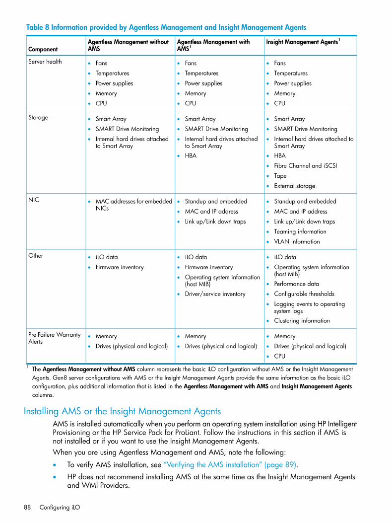
Table 8 Information provided by Agentless Management and Insight Management Agents
Insight Management Agents1Agentless Management withAMS1
Agentless Management withoutAMSComponent
Server health • Fans• Fans• Fans
• ••Temperatures TemperaturesTemperatures
•• •Power suppliesPower supplies Power supplies
••• MemoryMemoryMemory
• ••CPU CPUCPU
Storage • Smart Array• Smart Array• Smart Array
• ••SMART Drive Monitoring SMART Drive MonitoringSMART Drive Monitoring
•• •Internal hard drives attachedto Smart Array
Internal hard drives attachedto Smart Array
Internal hard drives attached toSmart Array
•• HBAHBA
• Fibre Channel and iSCSI
• Tape
• External storage
• MAC addresses for embeddedNICs
NIC • Standup and embedded• Standup and embedded
• •MAC and IP address MAC and IP address
•• Link up/Link down trapsLink up/Link down traps
• Teaming information
• VLAN information
Other • iLO data• iLO data• iLO data
• ••Firmware inventory Operating system information(host MIB)
Firmware inventory
• Operating system information(host MIB) • Performance data
• •Driver/service inventory Configurable thresholds
• Logging events to operatingsystem logs
• Clustering information
Pre-Failure WarrantyAlerts
• Memory• Memory• Memory
• ••Drives (physical and logical) Drives (physical and logical)Drives (physical and logical)
• CPU
1 The Agentless Management without AMS column represents the basic iLO configuration without AMS or the Insight ManagementAgents. Gen8 server configurations with AMS or the Insight Management Agents provide the same information as the basic iLOconfiguration, plus additional information that is listed in the Agentless Management with AMS and Insight Management Agentscolumns.
Installing AMS or the Insight Management AgentsAMS is installed automatically when you perform an operating system installation using HP IntelligentProvisioning or the HP Service Pack for ProLiant. Follow the instructions in this section if AMS isnot installed or if you want to use the Insight Management Agents.When you are using Agentless Management and AMS, note the following:
• To verify AMS installation, see “Verifying the AMS installation” (page 89).
• HP does not recommend installing AMS at the same time as the Insight Management Agentsand WMI Providers.
88 Configuring iLO
• If you must run AMS with the Insight Management Agents on Linux systems, start the hp-amsdaemon process first, and then decrease the number of traditional agents (for example,cmasm2d) running on the system. For more information about AMS on Linux systems, see themanpage for hpHelper, the AMS daemon process.
• When you install AMS on Windows systems, the Agentless Management Service ControlPanel is installed. You can use the Control Panel to configure SNMP settings, to enable ordisable AMS, and to remove AMS.
• AMS writes operating system configuration information and critical events to the Active HealthSystem Log.
• Use one of the following methods to obtain the AMS software or the Insight ManagementAgents:
◦ HP Service Pack for ProLiant (Windows, Red Hat, SLES)—Navigate to the following websiteto download the SPP: http://www.hp.com/go/spp.For instructions on using the HP Service Pack for ProLiant to install AMS or the InsightManagement Agents, see the Service Pack for ProLiant documentation.
◦ HP Support Center (Windows, Red Hat, SLES, VMware)1. Navigate to the technical support page on the HP website: http://www.hp.com/
support.2. Select a country or region.
The HP Support page opens.3. Click the Drivers & Downloads link.
In the search box, enter the server model that you are using (for example, DL360p).A list of servers is displayed.
4. Click the link for your server.The HP Support Center page for the server opens.
5. Click the link for the server operating system.6. Download the software.7. Follow the installation instructions provided with the downloaded software.
◦ Software Delivery Repository (Ubuntu)—Download AMS or the Insight ManagementAgents from the mcp section of the Software Delivery Repository at http://downloads.linux.hp.com/SDR/index.html.
◦ Software Delivery Repository (VMware)—Download AMS or the Insight ManagementAgents from the vibsdepot section of the Software Delivery Repository website at http://downloads.linux.hp.com/SDR/index.html.AMS is also included in the customized HP VMware ISO images that are released on HPSoftware Depot (http://www.hp.com/go/softwaredepot).
Verifying the AMS installationUse the following procedures to verify the AMS installation on Windows, Linux, and VMwaresystems.
Verifying AMS installation: WindowsTo verify that AMS is enabled on a Windows system:1. Open the Windows Control Panel.
If the Agentless Management Service Control Panel is present, then AMS is installed.
Configuring iLO Management settings 89
2. Open the Agentless Management Service Control Panel.3. Click the Service tab.
If AMS is enabled, the following message appears:Agentless Management Service (AMS) is enabled.
Verifying AMS installation: SUSE and Red HatTo verify that AMS is installed on a SUSE or Red Hat system, enter the following command:rpm –qi hp-ams
To verify that AMS is running on a SUSE or Red Hat system, enter the following command:service hp-ams status
Verifying AMS installation: VMwareTo verify that AMS is installed on a VMware system:1. Access the VMware host from the VMware vSphere Client.2. Navigate to the server’s Inventory→Configuration→Health Status tab.3. Click the plus sign (+) next to Software Components.
The software installed on the host is listed. The AMS component includes the string hp-ams.
NOTE: The full name of the AMS component is different for each supported version ofESX/ESXi.
To verify that AMS is running on a VMware system, enter the following command:service hp-ams status
Verifying AMS installation: UbuntuTo verify that AMS is installed on an Ubuntu system, enter the following command:dpkg –l hp-ams
To verify that AMS is running on an Ubuntu system, enter the following command:sudo service hp-ams status
Configuring SNMP settings1. Navigate to the Administration→Management page.2. Click the SNMP Settings tab, as shown in Figure 37 (page 91).
90 Configuring iLO
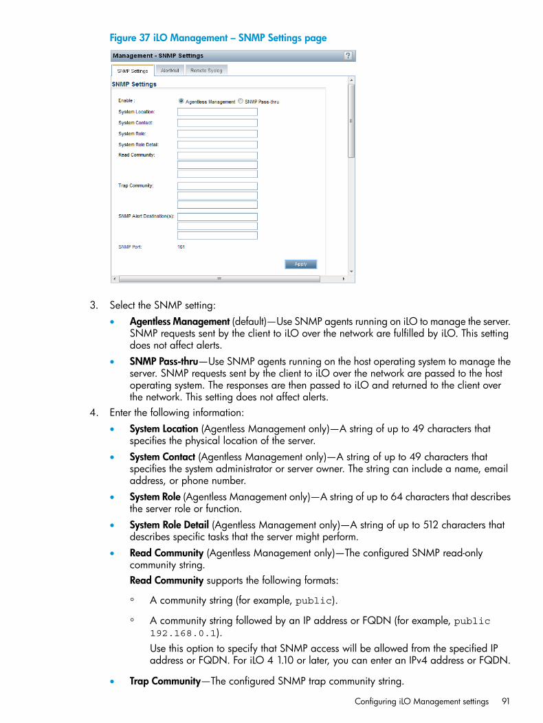
Figure 37 iLO Management – SNMP Settings page
3. Select the SNMP setting:• Agentless Management (default)—Use SNMP agents running on iLO to manage the server.
SNMP requests sent by the client to iLO over the network are fulfilled by iLO. This settingdoes not affect alerts.
• SNMP Pass-thru—Use SNMP agents running on the host operating system to manage theserver. SNMP requests sent by the client to iLO over the network are passed to the hostoperating system. The responses are then passed to iLO and returned to the client overthe network. This setting does not affect alerts.
4. Enter the following information:• System Location (Agentless Management only)—A string of up to 49 characters that
specifies the physical location of the server.• System Contact (Agentless Management only)—A string of up to 49 characters that
specifies the system administrator or server owner. The string can include a name, emailaddress, or phone number.
• System Role (Agentless Management only)—A string of up to 64 characters that describesthe server role or function.
• System Role Detail (Agentless Management only)—A string of up to 512 characters thatdescribes specific tasks that the server might perform.
• Read Community (Agentless Management only)—The configured SNMP read-onlycommunity string.Read Community supports the following formats:
◦ A community string (for example, public).
◦ A community string followed by an IP address or FQDN (for example, public192.168.0.1).Use this option to specify that SNMP access will be allowed from the specified IPaddress or FQDN. For iLO 4 1.10 or later, you can enter an IPv4 address or FQDN.
• Trap Community—The configured SNMP trap community string.
Configuring iLO Management settings 91
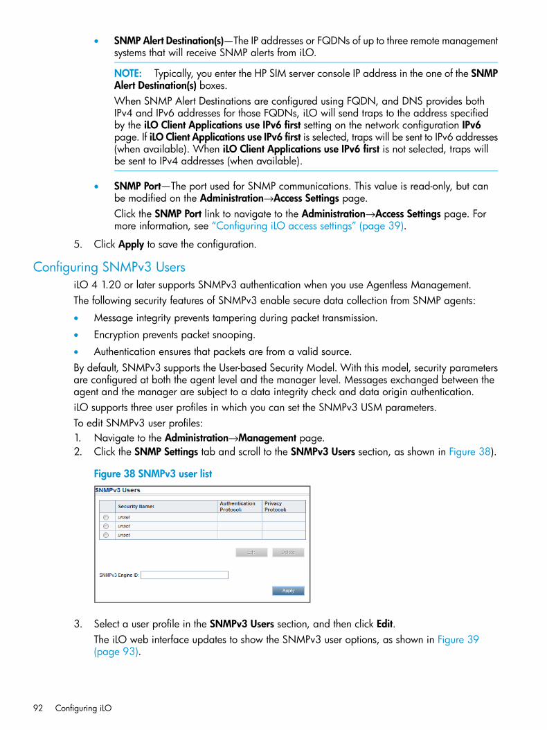
• SNMP Alert Destination(s)—The IP addresses or FQDNs of up to three remote managementsystems that will receive SNMP alerts from iLO.
NOTE: Typically, you enter the HP SIM server console IP address in the one of the SNMPAlert Destination(s) boxes.When SNMP Alert Destinations are configured using FQDN, and DNS provides bothIPv4 and IPv6 addresses for those FQDNs, iLO will send traps to the address specifiedby the iLO Client Applications use IPv6 first setting on the network configuration IPv6page. If iLO Client Applications use IPv6 first is selected, traps will be sent to IPv6 addresses(when available). When iLO Client Applications use IPv6 first is not selected, traps willbe sent to IPv4 addresses (when available).
• SNMP Port—The port used for SNMP communications. This value is read-only, but canbe modified on the Administration→Access Settings page.Click the SNMP Port link to navigate to the Administration→Access Settings page. Formore information, see “Configuring iLO access settings” (page 39).
5. Click Apply to save the configuration.
Configuring SNMPv3 UsersiLO 4 1.20 or later supports SNMPv3 authentication when you use Agentless Management.The following security features of SNMPv3 enable secure data collection from SNMP agents:
• Message integrity prevents tampering during packet transmission.
• Encryption prevents packet snooping.
• Authentication ensures that packets are from a valid source.By default, SNMPv3 supports the User-based Security Model. With this model, security parametersare configured at both the agent level and the manager level. Messages exchanged between theagent and the manager are subject to a data integrity check and data origin authentication.iLO supports three user profiles in which you can set the SNMPv3 USM parameters.To edit SNMPv3 user profiles:1. Navigate to the Administration→Management page.2. Click the SNMP Settings tab and scroll to the SNMPv3 Users section, as shown in Figure 38).
Figure 38 SNMPv3 user list
3. Select a user profile in the SNMPv3 Users section, and then click Edit.The iLO web interface updates to show the SNMPv3 user options, as shown in Figure 39(page 93).
92 Configuring iLO
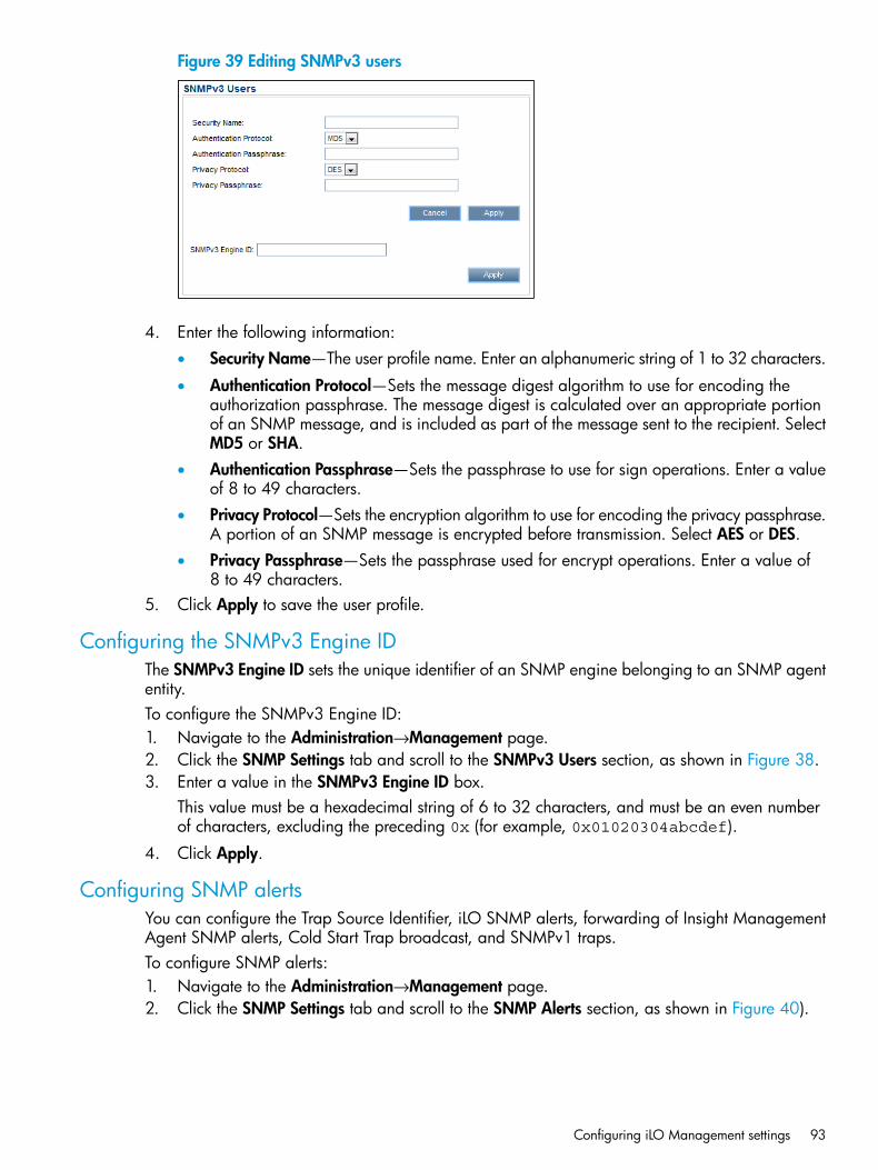
Figure 39 Editing SNMPv3 users
4. Enter the following information:• Security Name—The user profile name. Enter an alphanumeric string of 1 to 32 characters.
• Authentication Protocol—Sets the message digest algorithm to use for encoding theauthorization passphrase. The message digest is calculated over an appropriate portionof an SNMP message, and is included as part of the message sent to the recipient. SelectMD5 or SHA.
• Authentication Passphrase—Sets the passphrase to use for sign operations. Enter a valueof 8 to 49 characters.
• Privacy Protocol—Sets the encryption algorithm to use for encoding the privacy passphrase.A portion of an SNMP message is encrypted before transmission. Select AES or DES.
• Privacy Passphrase—Sets the passphrase used for encrypt operations. Enter a value of8 to 49 characters.
5. Click Apply to save the user profile.
Configuring the SNMPv3 Engine IDThe SNMPv3 Engine ID sets the unique identifier of an SNMP engine belonging to an SNMP agententity.To configure the SNMPv3 Engine ID:1. Navigate to the Administration→Management page.2. Click the SNMP Settings tab and scroll to the SNMPv3 Users section, as shown in Figure 38.3. Enter a value in the SNMPv3 Engine ID box.
This value must be a hexadecimal string of 6 to 32 characters, and must be an even numberof characters, excluding the preceding 0x (for example, 0x01020304abcdef).
4. Click Apply.
Configuring SNMP alertsYou can configure the Trap Source Identifier, iLO SNMP alerts, forwarding of Insight ManagementAgent SNMP alerts, Cold Start Trap broadcast, and SNMPv1 traps.To configure SNMP alerts:1. Navigate to the Administration→Management page.2. Click the SNMP Settings tab and scroll to the SNMP Alerts section, as shown in Figure 40).
Configuring iLO Management settings 93
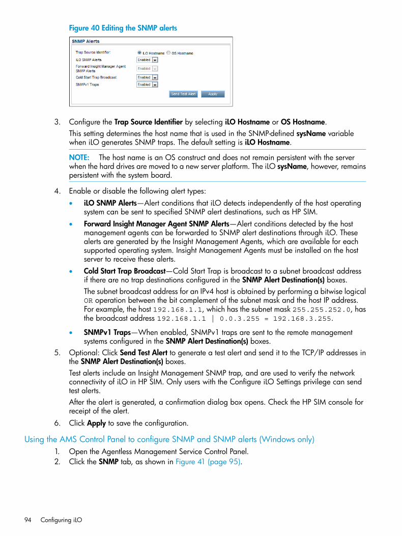
Figure 40 Editing the SNMP alerts
3. Configure the Trap Source Identifier by selecting iLO Hostname or OS Hostname.This setting determines the host name that is used in the SNMP-defined sysName variablewhen iLO generates SNMP traps. The default setting is iLO Hostname.
NOTE: The host name is an OS construct and does not remain persistent with the serverwhen the hard drives are moved to a new server platform. The iLO sysName, however, remainspersistent with the system board.
4. Enable or disable the following alert types:• iLO SNMP Alerts—Alert conditions that iLO detects independently of the host operating
system can be sent to specified SNMP alert destinations, such as HP SIM.• Forward Insight Manager Agent SNMP Alerts—Alert conditions detected by the host
management agents can be forwarded to SNMP alert destinations through iLO. Thesealerts are generated by the Insight Management Agents, which are available for eachsupported operating system. Insight Management Agents must be installed on the hostserver to receive these alerts.
• Cold Start Trap Broadcast—Cold Start Trap is broadcast to a subnet broadcast addressif there are no trap destinations configured in the SNMP Alert Destination(s) boxes.The subnet broadcast address for an IPv4 host is obtained by performing a bitwise logicalOR operation between the bit complement of the subnet mask and the host IP address.For example, the host 192.168.1.1, which has the subnet mask 255.255.252.0, hasthe broadcast address 192.168.1.1 | 0.0.3.255 = 192.168.3.255.
• SNMPv1 Traps—When enabled, SNMPv1 traps are sent to the remote managementsystems configured in the SNMP Alert Destination(s) boxes.
5. Optional: Click Send Test Alert to generate a test alert and send it to the TCP/IP addresses inthe SNMP Alert Destination(s) boxes.Test alerts include an Insight Management SNMP trap, and are used to verify the networkconnectivity of iLO in HP SIM. Only users with the Configure iLO Settings privilege can sendtest alerts.After the alert is generated, a confirmation dialog box opens. Check the HP SIM console forreceipt of the alert.
6. Click Apply to save the configuration.
Using the AMS Control Panel to configure SNMP and SNMP alerts (Windows only)1. Open the Agentless Management Service Control Panel.2. Click the SNMP tab, as shown in Figure 41 (page 95).
94 Configuring iLO
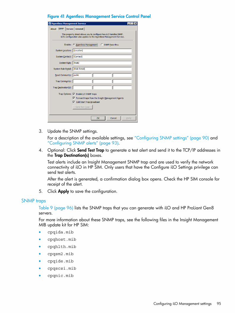
Figure 41 Agentless Management Service Control Panel
3. Update the SNMP settings.For a description of the available settings, see “Configuring SNMP settings” (page 90) and“Configuring SNMP alerts” (page 93).
4. Optional: Click Send Test Trap to generate a test alert and send it to the TCP/IP addresses inthe Trap Destination(s) boxes.Test alerts include an Insight Management SNMP trap and are used to verify the networkconnectivity of iLO in HP SIM. Only users that have the Configure iLO Settings privilege cansend test alerts.After the alert is generated, a confirmation dialog box opens. Check the HP SIM console forreceipt of the alert.
5. Click Apply to save the configuration.
SNMP trapsTable 9 (page 96) lists the SNMP traps that you can generate with iLO and HP ProLiant Gen8servers.For more information about these SNMP traps, see the following files in the Insight ManagementMIB update kit for HP SIM:• cpqida.mib
• cpqhost.mib
• cpqhlth.mib
• cpqsm2.mib
• cpqide.mib
• cpqscsi.mib
• cpqnic.mib
Configuring iLO Management settings 95
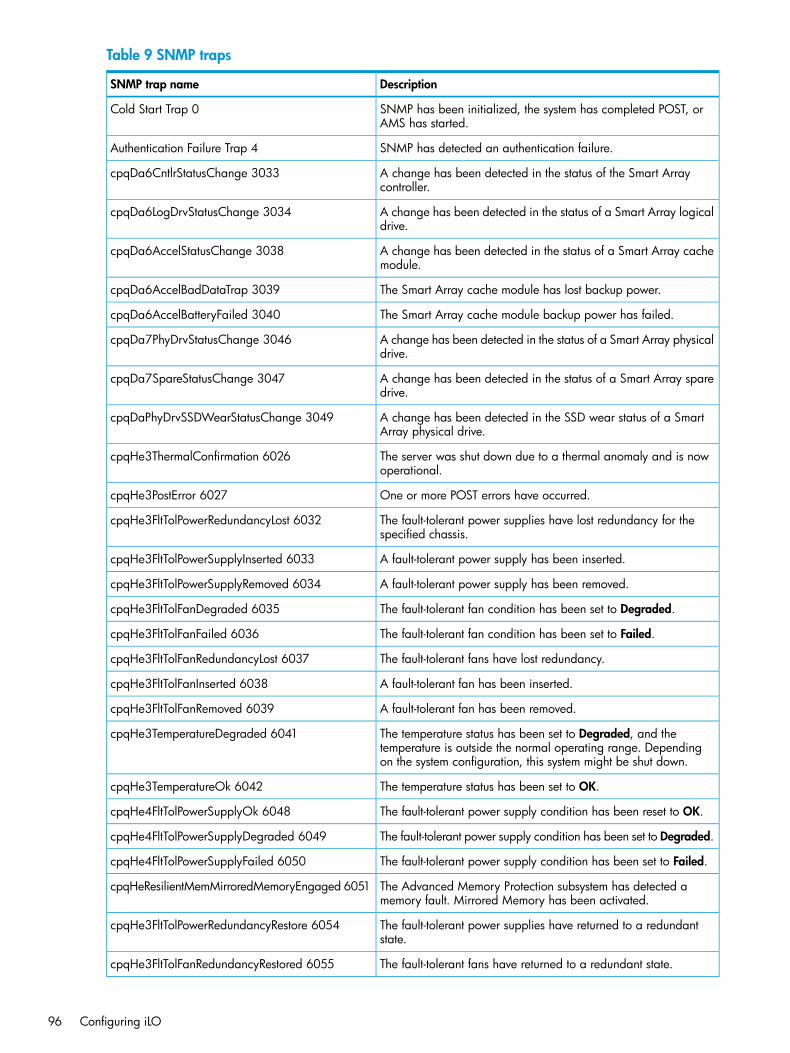
Table 9 SNMP traps
DescriptionSNMP trap name
SNMP has been initialized, the system has completed POST, orAMS has started.
Cold Start Trap 0
SNMP has detected an authentication failure.Authentication Failure Trap 4
A change has been detected in the status of the Smart Arraycontroller.
cpqDa6CntlrStatusChange 3033
A change has been detected in the status of a Smart Array logicaldrive.
cpqDa6LogDrvStatusChange 3034
A change has been detected in the status of a Smart Array cachemodule.
cpqDa6AccelStatusChange 3038
The Smart Array cache module has lost backup power.cpqDa6AccelBadDataTrap 3039
The Smart Array cache module backup power has failed.cpqDa6AccelBatteryFailed 3040
A change has been detected in the status of a Smart Array physicaldrive.
cpqDa7PhyDrvStatusChange 3046
A change has been detected in the status of a Smart Array sparedrive.
cpqDa7SpareStatusChange 3047
A change has been detected in the SSD wear status of a SmartArray physical drive.
cpqDaPhyDrvSSDWearStatusChange 3049
The server was shut down due to a thermal anomaly and is nowoperational.
cpqHe3ThermalConfirmation 6026
One or more POST errors have occurred.cpqHe3PostError 6027
The fault-tolerant power supplies have lost redundancy for thespecified chassis.
cpqHe3FltTolPowerRedundancyLost 6032
A fault-tolerant power supply has been inserted.cpqHe3FltTolPowerSupplyInserted 6033
A fault-tolerant power supply has been removed.cpqHe3FltTolPowerSupplyRemoved 6034
The fault-tolerant fan condition has been set to Degraded.cpqHe3FltTolFanDegraded 6035
The fault-tolerant fan condition has been set to Failed.cpqHe3FltTolFanFailed 6036
The fault-tolerant fans have lost redundancy.cpqHe3FltTolFanRedundancyLost 6037
A fault-tolerant fan has been inserted.cpqHe3FltTolFanInserted 6038
A fault-tolerant fan has been removed.cpqHe3FltTolFanRemoved 6039
The temperature status has been set to Degraded, and thetemperature is outside the normal operating range. Dependingon the system configuration, this system might be shut down.
cpqHe3TemperatureDegraded 6041
The temperature status has been set to OK.cpqHe3TemperatureOk 6042
The fault-tolerant power supply condition has been reset to OK.cpqHe4FltTolPowerSupplyOk 6048
The fault-tolerant power supply condition has been set to Degraded.cpqHe4FltTolPowerSupplyDegraded 6049
The fault-tolerant power supply condition has been set to Failed.cpqHe4FltTolPowerSupplyFailed 6050
The Advanced Memory Protection subsystem has detected amemory fault. Mirrored Memory has been activated.
cpqHeResilientMemMirroredMemoryEngaged 6051
The fault-tolerant power supplies have returned to a redundantstate.
cpqHe3FltTolPowerRedundancyRestore 6054
The fault-tolerant fans have returned to a redundant state.cpqHe3FltTolFanRedundancyRestored 6055
96 Configuring iLO
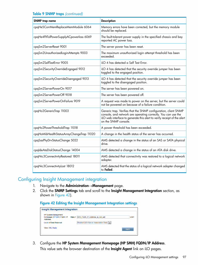
Table 9 SNMP traps (continued)
DescriptionSNMP trap name
Memory errors have been corrected, but the memory moduleshould be replaced.
cpqHe5CorrMemReplaceMemModule 6064
The fault-tolerant power supply in the specified chassis and bayreported AC power loss.
cpqHe4FltTolPowerSupplyACpowerloss 6069
The server power has been reset.cpqSm2ServerReset 9001
The maximum unauthorized login attempt threshold has beenexceeded.
cpqSm2UnauthorizedLoginAttempts 9003
iLO 4 has detected a Self Test Error.cpqSm2SelfTestError 9005
iLO 4 has detected that the security override jumper has beentoggled to the engaged position.
cpqSm2SecurityOverrideEngaged 9012
iLO 4 has detected that the security override jumper has beentoggled to the disengaged position.
cpqSm2SecurityOverrideDisengaged 9013
The server has been powered on.cpqSm2ServerPowerOn 9017
The server has been powered off.cpqSm2ServerPowerOff 9018
A request was made to power on the server, but the server couldnot be powered on because of a failure condition.
cpqSm2ServerPowerOnFailure 9019
Generic trap. Verifies that the SNMP configuration, client SNMPconsole, and network are operating correctly. You can use the
cpqHo2GenericTrap 11003
iLO web interface to generate this alert to verify receipt of the alerton the SNMP console.
A power threshold has been exceeded.cpqHo2PowerThresholdTrap 11018
A change in the health status of the server has occurred.cpqHoMibHealthStatusArrayChangeTrap 11020
AMS detected a change in the status of an SAS or SATA physicaldrive.
cpqSasPhyDrvStatusChange 5022
AMS detected a change in the status of an ATA disk drive.cpqIdeAtaDiskStatusChange 14004
AMS detected that connectivity was restored to a logical networkadapter.
cpqNic3ConnectivityRestored 18011
AMS detected that the status of a logical network adapter changedto Failed.
cpqNic3ConnectivityLost 18012
Configuring Insight Management integration1. Navigate to the Administration→Management page.2. Click the SNMP Settings tab and scroll to the Insight Management Integration section, as
shown in Figure 42).
Figure 42 Editing the Insight Management Integration settings
3. Configure the HP System Management Homepage (HP SMH) FQDN/IP Address.This value sets the browser destination of the Insight Agent link on iLO pages.
Configuring iLO Management settings 97
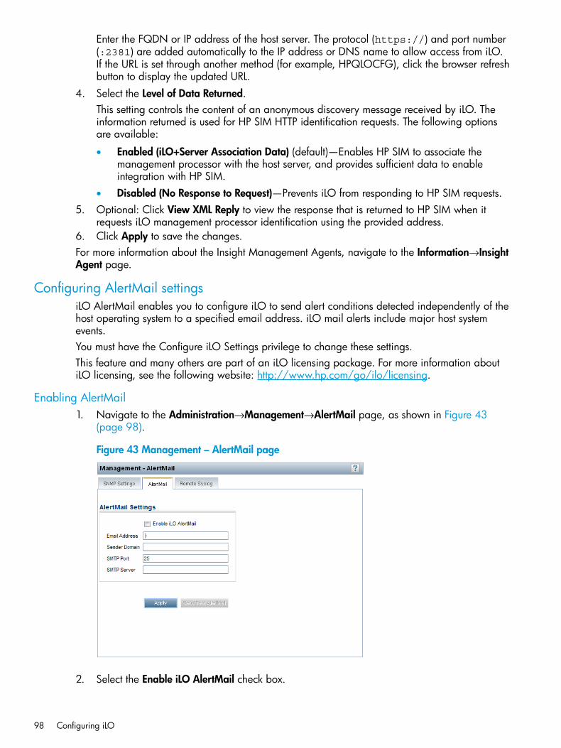
Enter the FQDN or IP address of the host server. The protocol (https://) and port number(:2381) are added automatically to the IP address or DNS name to allow access from iLO.If the URL is set through another method (for example, HPQLOCFG), click the browser refreshbutton to display the updated URL.
4. Select the Level of Data Returned.This setting controls the content of an anonymous discovery message received by iLO. Theinformation returned is used for HP SIM HTTP identification requests. The following optionsare available:
• Enabled (iLO+Server Association Data) (default)—Enables HP SIM to associate themanagement processor with the host server, and provides sufficient data to enableintegration with HP SIM.
• Disabled (No Response to Request)—Prevents iLO from responding to HP SIM requests.5. Optional: Click View XML Reply to view the response that is returned to HP SIM when it
requests iLO management processor identification using the provided address.6. Click Apply to save the changes.For more information about the Insight Management Agents, navigate to the Information→InsightAgent page.
Configuring AlertMail settingsiLO AlertMail enables you to configure iLO to send alert conditions detected independently of thehost operating system to a specified email address. iLO mail alerts include major host systemevents.You must have the Configure iLO Settings privilege to change these settings.This feature and many others are part of an iLO licensing package. For more information aboutiLO licensing, see the following website: http://www.hp.com/go/ilo/licensing.
Enabling AlertMail1. Navigate to the Administration→Management→AlertMail page, as shown in Figure 43
(page 98).
Figure 43 Management – AlertMail page
2. Select the Enable iLO AlertMail check box.
98 Configuring iLO
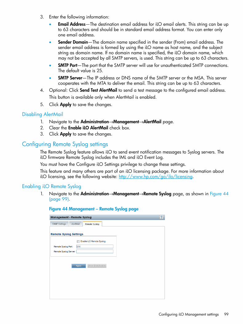
3. Enter the following information:• Email Address—The destination email address for iLO email alerts. This string can be up
to 63 characters and should be in standard email address format. You can enter onlyone email address.
• Sender Domain—The domain name specified in the sender (From) email address. Thesender email address is formed by using the iLO name as host name, and the subjectstring as domain name. If no domain name is specified, the iLO domain name, whichmay not be accepted by all SMTP servers, is used. This string can be up to 63 characters.
• SMTP Port—The port that the SMTP server will use for unauthenticated SMTP connections.The default value is 25.
• SMTP Server—The IP address or DNS name of the SMTP server or the MSA. This servercooperates with the MTA to deliver the email. This string can be up to 63 characters.
4. Optional: Click Send Test AlertMail to send a test message to the configured email address.This button is available only when AlertMail is enabled.
5. Click Apply to save the changes.
Disabling AlertMail1. Navigate to the Administration→Management→AlertMail page.2. Clear the Enable iLO AlertMail check box.3. Click Apply to save the changes.
Configuring Remote Syslog settingsThe Remote Syslog feature allows iLO to send event notification messages to Syslog servers. TheiLO firmware Remote Syslog includes the IML and iLO Event Log.You must have the Configure iLO Settings privilege to change these settings.This feature and many others are part of an iLO licensing package. For more information aboutiLO licensing, see the following website: http://www.hp.com/go/ilo/licensing.
Enabling iLO Remote Syslog1. Navigate to the Administration→Management→Remote Syslog page, as shown in Figure 44
(page 99).
Figure 44 Management – Remote Syslog page
Configuring iLO Management settings 99
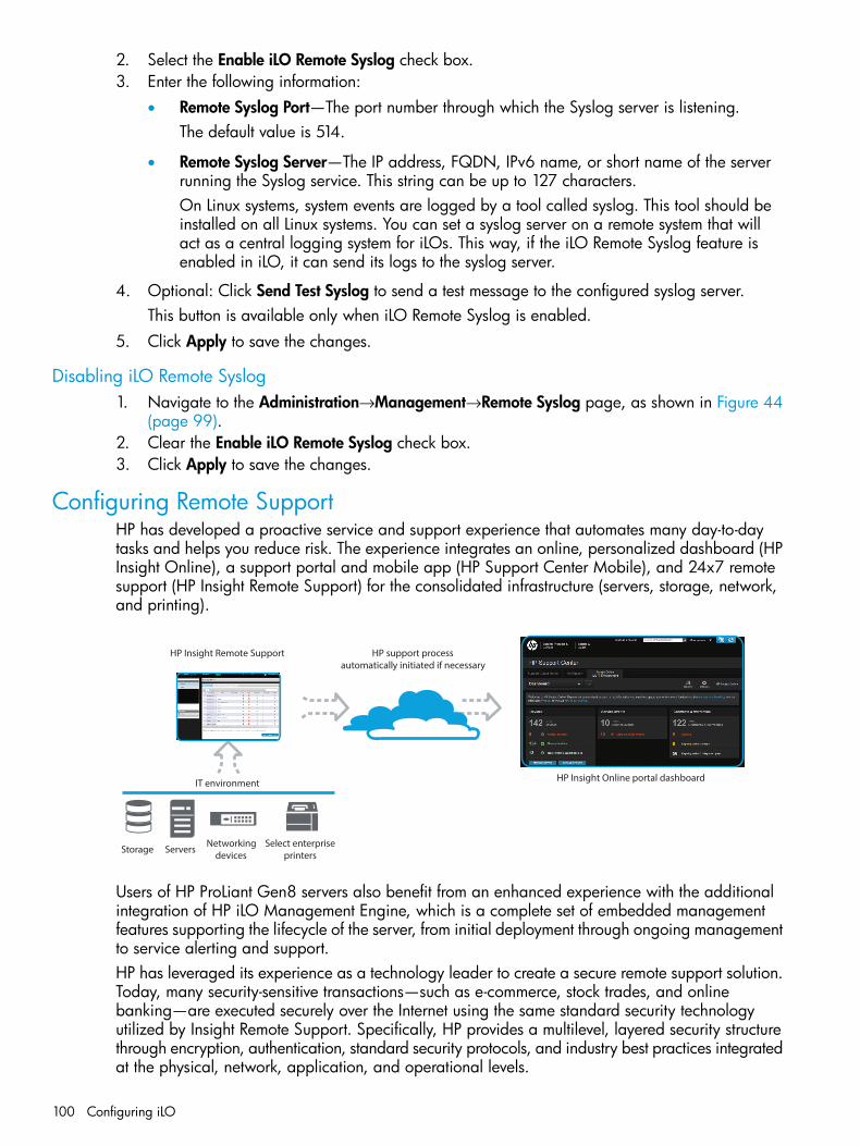
2. Select the Enable iLO Remote Syslog check box.3. Enter the following information:
• Remote Syslog Port—The port number through which the Syslog server is listening.The default value is 514.
• Remote Syslog Server—The IP address, FQDN, IPv6 name, or short name of the serverrunning the Syslog service. This string can be up to 127 characters.On Linux systems, system events are logged by a tool called syslog. This tool should beinstalled on all Linux systems. You can set a syslog server on a remote system that willact as a central logging system for iLOs. This way, if the iLO Remote Syslog feature isenabled in iLO, it can send its logs to the syslog server.
4. Optional: Click Send Test Syslog to send a test message to the configured syslog server.This button is available only when iLO Remote Syslog is enabled.
5. Click Apply to save the changes.
Disabling iLO Remote Syslog1. Navigate to the Administration→Management→Remote Syslog page, as shown in Figure 44
(page 99).2. Clear the Enable iLO Remote Syslog check box.3. Click Apply to save the changes.
Configuring Remote SupportHP has developed a proactive service and support experience that automates many day-to-daytasks and helps you reduce risk. The experience integrates an online, personalized dashboard (HPInsight Online), a support portal and mobile app (HP Support Center Mobile), and 24x7 remotesupport (HP Insight Remote Support) for the consolidated infrastructure (servers, storage, network,and printing).
HP support process automatically initiated if necessary
HP Insight Online portal dashboardIT environment
HP Insight Remote Support
Storage Servers Networkingdevices
Select enterpriseprinters
Users of HP ProLiant Gen8 servers also benefit from an enhanced experience with the additionalintegration of HP iLO Management Engine, which is a complete set of embedded managementfeatures supporting the lifecycle of the server, from initial deployment through ongoing managementto service alerting and support.HP has leveraged its experience as a technology leader to create a secure remote support solution.Today, many security-sensitive transactions—such as e-commerce, stock trades, and onlinebanking—are executed securely over the Internet using the same standard security technologyutilized by Insight Remote Support. Specifically, HP provides a multilevel, layered security structurethrough encryption, authentication, standard security protocols, and industry best practices integratedat the physical, network, application, and operational levels.
100 Configuring iLO
Interactions between HP and your enterprise network are restricted and tightly controlled througha single, secure access point. HP’s remote monitoring and support capabilities, along with anysupport information collected, are used only to provide you with world-class HP support. Thisinformation is managed according to HP’s strict privacy policies. These policies have been reviewedby TRUSTe, an independent industry privacy organization, and have achieved their Web Privacy– Cloud Certification.
Data collected by Insight Remote SupportBy registering for Insight Remote Support, you agree to send registration, service events,configuration, and Active Health System data to HP. All data collected and sent to HP will be usedto provide remote support and quality improvement. The collected data is managed according tothe HP privacy statement, available at http://www.hp.com/go/privacy.When a server is registered for Insight Remote Support, Active Health System information is sentto HP every 7 days, and configuration information is sent every 30 days. You can change thefrequency by using the Insight RS software. The following information is sent to HP:
• Registration—During server registration, iLO sends data to uniquely identify the serverhardware.Registration data includes the following:
◦ Server model
◦ Serial number
◦ iLO NIC address
For more information about registering for Remote Support, see “Registering for Insight RemoteSupport” (page 102).
• Service events—When service events are recorded, iLO sends data to uniquely identify therelevant hardware component.Service event data includes the following:
◦ Server model
◦ Serial number
◦ Part number of the hardware component
◦ Description, location, and other identifying characteristics of the hardware component
For more information, see “Working with Insight Remote Support service events” (page 104).
• Configuration—During data collection, iLO sends information to HP to enable proactive adviceand consulting.Configuration data includes the following:
◦ Server model
◦ Serial number
◦ Processor model, speed, and utilization
◦ Storage capacity, speed, and utilization
◦ Memory capacity, speed, and utilization
◦ Firmware/BIOS
◦ Installed drivers, services, and applications (if AMS is installed)
Configuring Remote Support 101

For more information, see “Viewing and sending Remote Support data collection information”(page 106).
PrerequisitesBefore registering, verify that the following prerequisites are met:
• Version 1.10 or later of the iLO firmware is installed.For instructions, see “Updating firmware” (page 25).
• The iLO time zone is set.If the time zone is not set, service events and data collection details are displayed with a GMToffset in the Insight RS Console.For instructions, see “Configuring SNTP settings” (page 86).
• The RIBCL protocol credentials for the ProLiant Gen8 server are configured in the Insight RSConsole.For more information about the RIBCL protocol credentials, see the HP Insight Remote SupportInstallation and Configuration Guide at http://www.hp.com/go/insightremotesupport/docs.
• Insight RS version 7.0.5 or later is installed and configured on the Insight RS Hosting Device.You must be running Insight RS software version 7.0.5 or later to use the built-in ProLiant Gen8embedded Remote Support feature.
• Optional: AMS is installed and the operating system is running on the ProLiant Gen8 serverthat you want to register.For more information about AMS, see “Installing AMS or the Insight Management Agents”(page 88).If you do not install AMS, your server will be identified in Insight RS by its serial number insteadof the host name or IP address.
• The HP ProLiant iLO 3/4 Channel Interface Driver is installed.For more information, see “Installing the iLO drivers” (page 22).
Registering for Insight Remote SupportUse the following procedure to register a ProLiant Gen8 server for Insight Remote Support.You must have the Configure iLO Settings privilege to modify the iLO Remote Support settings.1. Verify that the system meets the prerequisites for using Insight Remote Support.
For more information, see “Prerequisites” (page 102).2. Navigate to the Remote Support→Registration page, as shown in Figure 45 (page 103).
102 Configuring iLO
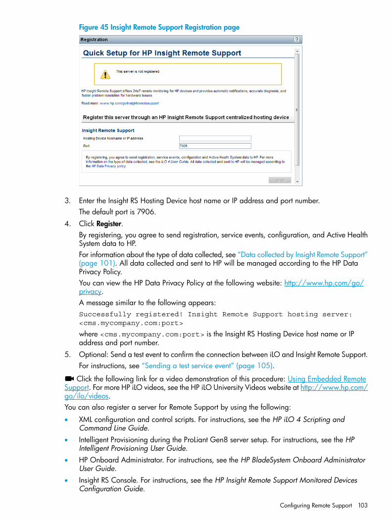
Figure 45 Insight Remote Support Registration page
3. Enter the Insight RS Hosting Device host name or IP address and port number.The default port is 7906.
4. Click Register.By registering, you agree to send registration, service events, configuration, and Active HealthSystem data to HP.For information about the type of data collected, see “Data collected by Insight Remote Support”(page 101). All data collected and sent to HP will be managed according to the HP DataPrivacy Policy.You can view the HP Data Privacy Policy at the following website: http://www.hp.com/go/privacy.A message similar to the following appears:Successfully registered! Insight Remote Support hosting server:<cms.mycompany.com:port>
where <cms.mycompany.com:port> is the Insight RS Hosting Device host name or IPaddress and port number.
5. Optional: Send a test event to confirm the connection between iLO and Insight Remote Support.For instructions, see “Sending a test service event” (page 105).
Click the following link for a video demonstration of this procedure: Using Embedded RemoteSupport. For more HP iLO videos, see the HP iLO University Videos website at http://www.hp.com/go/ilo/videos.You can also register a server for Remote Support by using the following:
• XML configuration and control scripts. For instructions, see the HP iLO 4 Scripting andCommand Line Guide.
• Intelligent Provisioning during the ProLiant Gen8 server setup. For instructions, see the HPIntelligent Provisioning User Guide.
• HP Onboard Administrator. For instructions, see the HP BladeSystem Onboard AdministratorUser Guide.
• Insight RS Console. For instructions, see the HP Insight Remote Support Monitored DevicesConfiguration Guide.
Configuring Remote Support 103
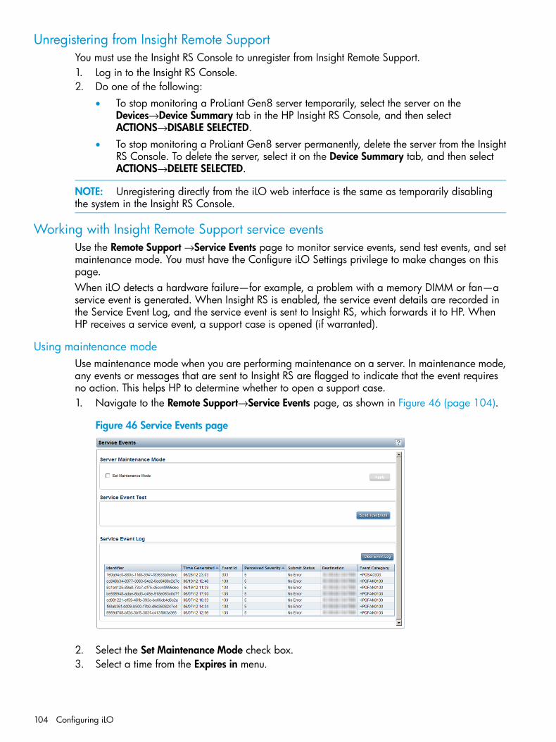
Unregistering from Insight Remote SupportYou must use the Insight RS Console to unregister from Insight Remote Support.1. Log in to the Insight RS Console.2. Do one of the following:
• To stop monitoring a ProLiant Gen8 server temporarily, select the server on theDevices→Device Summary tab in the HP Insight RS Console, and then selectACTIONS→DISABLE SELECTED.
• To stop monitoring a ProLiant Gen8 server permanently, delete the server from the InsightRS Console. To delete the server, select it on the Device Summary tab, and then selectACTIONS→DELETE SELECTED.
NOTE: Unregistering directly from the iLO web interface is the same as temporarily disablingthe system in the Insight RS Console.
Working with Insight Remote Support service eventsUse the Remote Support →Service Events page to monitor service events, send test events, and setmaintenance mode. You must have the Configure iLO Settings privilege to make changes on thispage.When iLO detects a hardware failure—for example, a problem with a memory DIMM or fan—aservice event is generated. When Insight RS is enabled, the service event details are recorded inthe Service Event Log, and the service event is sent to Insight RS, which forwards it to HP. WhenHP receives a service event, a support case is opened (if warranted).
Using maintenance modeUse maintenance mode when you are performing maintenance on a server. In maintenance mode,any events or messages that are sent to Insight RS are flagged to indicate that the event requiresno action. This helps HP to determine whether to open a support case.1. Navigate to the Remote Support→Service Events page, as shown in Figure 46 (page 104).
Figure 46 Service Events page
2. Select the Set Maintenance Mode check box.3. Select a time from the Expires in menu.
104 Configuring iLO
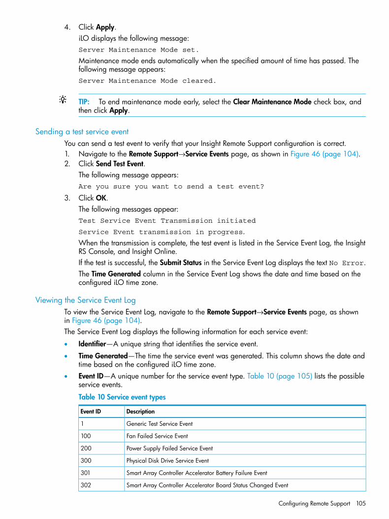
4. Click Apply.iLO displays the following message:Server Maintenance Mode set.
Maintenance mode ends automatically when the specified amount of time has passed. Thefollowing message appears:Server Maintenance Mode cleared.
TIP: To end maintenance mode early, select the Clear Maintenance Mode check box, andthen click Apply.
Sending a test service eventYou can send a test event to verify that your Insight Remote Support configuration is correct.1. Navigate to the Remote Support→Service Events page, as shown in Figure 46 (page 104).2. Click Send Test Event.
The following message appears:Are you sure you want to send a test event?
3. Click OK.The following messages appear:Test Service Event Transmission initiated
Service Event transmission in progress.When the transmission is complete, the test event is listed in the Service Event Log, the InsightRS Console, and Insight Online.If the test is successful, the Submit Status in the Service Event Log displays the text No Error.The Time Generated column in the Service Event Log shows the date and time based on theconfigured iLO time zone.
Viewing the Service Event LogTo view the Service Event Log, navigate to the Remote Support→Service Events page, as shownin Figure 46 (page 104).The Service Event Log displays the following information for each service event:
• Identifier—A unique string that identifies the service event.
• Time Generated—The time the service event was generated. This column shows the date andtime based on the configured iLO time zone.
• Event ID—A unique number for the service event type. Table 10 (page 105) lists the possibleservice events.
Table 10 Service event types
DescriptionEvent ID
Generic Test Service Event1
Fan Failed Service Event100
Power Supply Failed Service Event200
Physical Disk Drive Service Event300
Smart Array Controller Accelerator Battery Failure Event301
Smart Array Controller Accelerator Board Status Changed Event302
Configuring Remote Support 105
Table 10 Service event types (continued)
DescriptionEvent ID
Smart Array Controller Status Changed Event303
Memory Module Failed or Predicted to Fail Event400
• Perceived Severity—The severity of the event indication (for example, 5-Major, 7-Fatal).
• Submit Status—The status of the event submission. If the status is No error, the event wassubmitted successfully.
• Destination—The host name or IP address and port of the Insight RS Hosting Device thatreceived the service event.
• Event Category—The category of the event that matches the Message ID description in themessage registry.
Clearing the Service Event Log1. Navigate to the Remote Support→Service Events page, as shown in Figure 46 (page 104).2. Click Clear Event Log.
The following message appears:Are you sure you want to clear the Service Event Log?
3. Click OK.The following message appears:Service Event Log has been cleared.
Viewing and sending Remote Support data collection informationUse the Remote Support→Data Collections page to view information about the data and ActiveHealth System information that is sent to HP when a server is registered for Insight Remote Support.You can also send data collection information manually from this page.
Sending Data Collection informationInsight RS collects data from iLO and sends information about the server configuration to HP foranalysis and proactive services that are consistent with your warranty and existing serviceagreements. The data transmission frequency is configured in the Insight RS user interface on theInsight RS Hosting Device. For information about configuring the data collection schedule, see theHP Insight RS online help.The Data Collection Information section displays the following information:
• Last Data Collection Transmission—The date and time of the last data collection.
• Last Data Collection Transmission Status—The status of the last data transmission.Use the following procedure to send data collection information immediately:
106 Configuring iLO
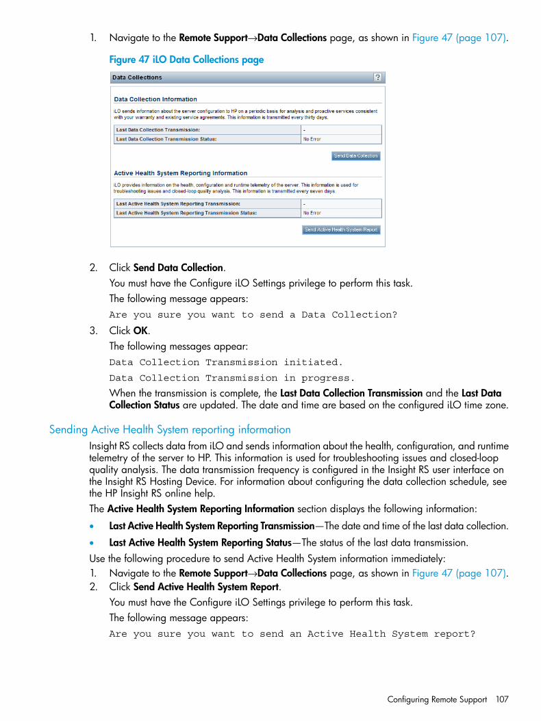
1. Navigate to the Remote Support→Data Collections page, as shown in Figure 47 (page 107).
Figure 47 iLO Data Collections page
2. Click Send Data Collection.You must have the Configure iLO Settings privilege to perform this task.The following message appears:Are you sure you want to send a Data Collection?
3. Click OK.The following messages appear:Data Collection Transmission initiated.
Data Collection Transmission in progress.
When the transmission is complete, the Last Data Collection Transmission and the Last DataCollection Status are updated. The date and time are based on the configured iLO time zone.
Sending Active Health System reporting informationInsight RS collects data from iLO and sends information about the health, configuration, and runtimetelemetry of the server to HP. This information is used for troubleshooting issues and closed-loopquality analysis. The data transmission frequency is configured in the Insight RS user interface onthe Insight RS Hosting Device. For information about configuring the data collection schedule, seethe HP Insight RS online help.The Active Health System Reporting Information section displays the following information:
• Last Active Health System Reporting Transmission—The date and time of the last data collection.
• Last Active Health System Reporting Status—The status of the last data transmission.Use the following procedure to send Active Health System information immediately:1. Navigate to the Remote Support→Data Collections page, as shown in Figure 47 (page 107).2. Click Send Active Health System Report.
You must have the Configure iLO Settings privilege to perform this task.The following message appears:Are you sure you want to send an Active Health System report?
Configuring Remote Support 107

3. Click OK.The following messages appear:Active Health System Transmission initiated
Active Health System Transmission in progress
The collected data includes Active Health System information from the last 7 days.When the transmission is complete, the Last Active Health System Reporting Transmission andthe Last Active Health System Reporting Status are updated. The date and time are based onthe configured iLO time zone.
NOTE: You can also download Active Health System information manually and send it to HP.For instructions, see “Using the HP Active Health System” (page 139).
108 Configuring iLO
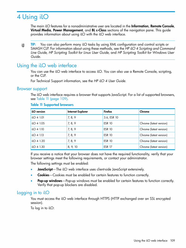
4 Using iLOThe main iLO features for a nonadministrative user are located in the Information, Remote Console,Virtual Media, Power Management, and BL c-Class sections of the navigation pane. This guideprovides information about using iLO with the iLO web interface.
TIP: You can also perform many iLO tasks by using XML configuration and control scripts orSMASH CLP. For information about using these methods, see the HP iLO 4 Scripting and CommandLine Guide, HP Scripting Toolkit for Linux User Guide, and HP Scripting Toolkit for Windows UserGuide.
Using the iLO web interfaceYou can use the iLO web interface to access iLO. You can also use a Remote Console, scripting,or the CLP.For Technical Support information, see the HP iLO 4 User Guide.
Browser supportThe iLO web interface requires a browser that supports JavaScript. For a list of supported browsers,see Table 11 (page 109).
Table 11 Supported browsers
ChromeFirefoxInternet ExploreriLO version
3.6, ESR 107, 8, 9iLO 4 1.01
Chrome (latest version)ESR 107, 8, 9iLO 4 1.05
Chrome (latest version)ESR 107, 8, 9iLO 4 1.10
Chrome (latest version)ESR 107, 8, 9iLO 4 1.13
Chrome (latest version)ESR 107, 8, 9iLO 4 1.20
Chrome (latest version)ESR 178, 9, 10iLO 4 1.30
If you receive a notice that your browser does not have the required functionality, verify that yourbrowser settings meet the following requirements, or contact your administrator.The following settings must be enabled:
• JavaScript—The iLO web interface uses client-side JavaScript extensively.
• Cookies—Cookies must be enabled for certain features to function correctly.
• Pop-up windows—Pop-up windows must be enabled for certain features to function correctly.Verify that pop-up blockers are disabled.
Logging in to iLOYou must access the iLO web interface through HTTPS (HTTP exchanged over an SSL encryptedsession).To log in to iLO:
Using the iLO web interface 109
1. Enter https://<iLO host name or IP address>.The iLO login page opens.If iLO is configured to use the Login Security Banner feature, a security message is displayedon the login page.For information about configuring the Login Security Banner, see “Configuring the LoginSecurity Banner” (page 71).
2. Enter an HP iLO user name and password, and then click Log In.Login problems might occur for the following reasons:
• You have recently upgraded the iLO firmware. You might need to clear your browser cachebefore attempting to log in again.
• You are not entering the login information correctly.
Passwords are case sensitive.◦◦ User names are not case sensitive. Uppercase and lowercase characters are treated the
same (for example, Administrator is treated as the same user as administrator).
• The account you are entering is not a valid iLO account.
• The account you are entering has been deleted, disabled, or locked out.
• The password for the account must be changed.
• You are attempting to sign in from an IP address that is not valid for the specified account.Contact the administrator if you continue to have problems.
If iLO is configured for Kerberos network authentication, the HP Zero Sign In button is displayedbelow the Log In button. Clicking the HP Zero Sign In button logs the user in to iLO without requiringthe user to enter a user name and password. If the Kerberos login fails, the user can log in byusing a user name and password.A failed Kerberos login might be due to one of the following reasons:• The client does not have a ticket or has an invalid ticket. Press Ctrl+Alt+Del to lock the client
PC and get a new ticket.• The browser is not configured correctly. The browser might display a dialog box requesting
credentials.• The Kerberos realm that the client PC is logged in to does not match the Kerberos realm for
which iLO is configured.• The computer account in Active Directory for iLO does not exist or is disabled.
• The user logged in to the client PC is not a member of a universal or global directory groupauthorized to access iLO.
• The key in the Kerberos keytab stored in iLO does not match the key in Active Directory.
• The KDC server address for which iLO is configured is incorrect.
• The date and time do not match between the client PC, the KDC server, and iLO.
• The DNS server is not working correctly. iLO requires a functioning DNS server for Kerberossupport.
Handling an unknown authorityIf the message Website Certified by an Unknown Authority is displayed, take thefollowing action:
110 Using iLO
1. View the certificate to ensure that you are browsing to the correct management server (not animposter).• Verify that the Issued To name is your management server. Perform any other steps you
feel necessary to verify the identity of the management server.• If you are not sure that this is the correct management server, do not proceed. You might
be browsing to an imposter and giving your sign-in credentials to that imposter when yousign in. Contact the administrator. Exit the certificate window, and then click No or Cancelto cancel the connection.
2. After verifying the items in Step 1, you have the following options:• Accept the certificate temporarily for this session.
• Accept the certificate permanently.
• Stop now and import the certificate into your browser from a file provided by youradministrator.
Using the iLO controlsWhen you log in to the iLO web interface, the controls at the bottom of the browser window areavailable from any iLO page.
• POWER—Use this menu to access the iLO Virtual Power features.
• UID—Use this button to turn the UID light on and off.
• Language—Use this menu to select a language or to navigate to the Access Settings→Languagepage, where you can install a language pack and configure other language-related settings.
• Health icon—Use this icon to view the overall health status for the server fans, temperaturesensors, and other monitored subsystems. Click the icon to view the status of the monitoredcomponents. Select a component to view more information about the component status.
Starting a remote management toolWhen iLO is under the control of a remote management tool, the iLO web interface displays amessage similar to the following on the iLO login page:Warning! Some iLO settings are managed by <remote management tool name>.Changes made directly in iLO will be out of sync with the centralizedsettings.
The name of the remote management tool is a link. Click the link to start the remote managementtool.
Language pack supportIf a language pack is currently installed in iLO, a language menu is available on the login screenfor you to select the language for the iLO session. This selection is saved in a browser cookie forfuture use.
Viewing iLO overview informationThe iLO Overview page displays high-level details about the server and iLO subsystem, as well aslinks to commonly used features.
Viewing system informationTo view iLO overview information, navigate to the Information→Overview page, as shown inFigure 48 (page 112).
Viewing iLO overview information 111
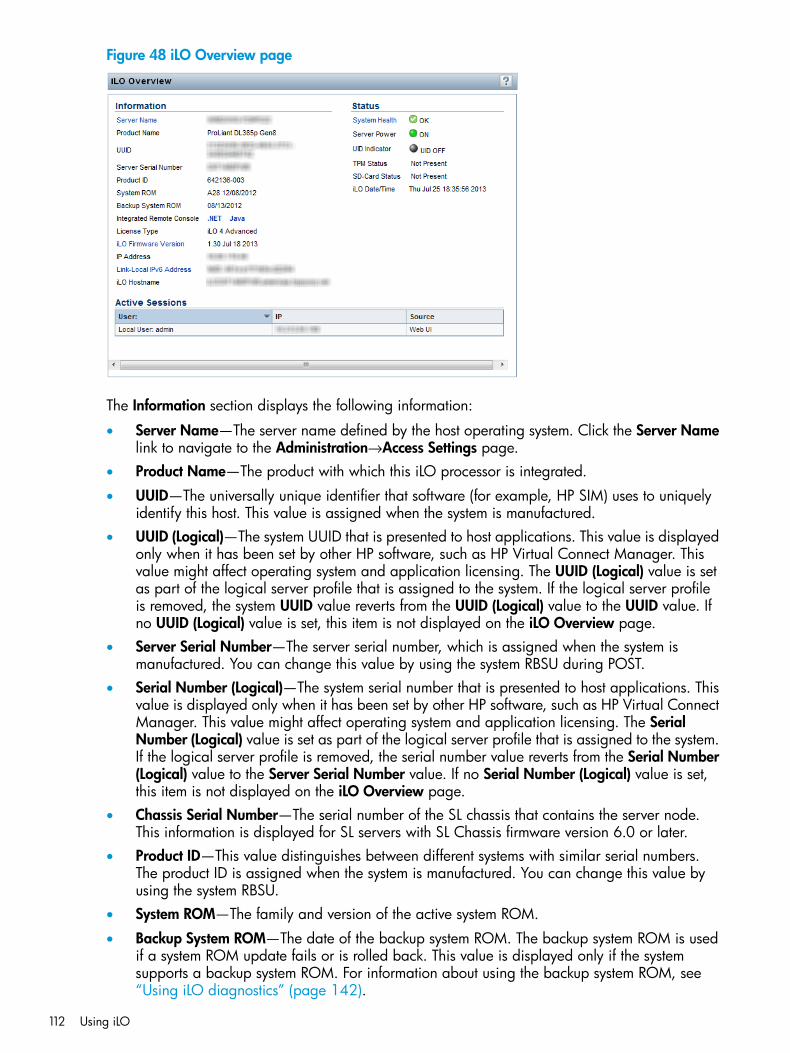
Figure 48 iLO Overview page
The Information section displays the following information:
• Server Name—The server name defined by the host operating system. Click the Server Namelink to navigate to the Administration→Access Settings page.
• Product Name—The product with which this iLO processor is integrated.
• UUID—The universally unique identifier that software (for example, HP SIM) uses to uniquelyidentify this host. This value is assigned when the system is manufactured.
• UUID (Logical)—The system UUID that is presented to host applications. This value is displayedonly when it has been set by other HP software, such as HP Virtual Connect Manager. Thisvalue might affect operating system and application licensing. The UUID (Logical) value is setas part of the logical server profile that is assigned to the system. If the logical server profileis removed, the system UUID value reverts from the UUID (Logical) value to the UUID value. Ifno UUID (Logical) value is set, this item is not displayed on the iLO Overview page.
• Server Serial Number—The server serial number, which is assigned when the system ismanufactured. You can change this value by using the system RBSU during POST.
• Serial Number (Logical)—The system serial number that is presented to host applications. Thisvalue is displayed only when it has been set by other HP software, such as HP Virtual ConnectManager. This value might affect operating system and application licensing. The SerialNumber (Logical) value is set as part of the logical server profile that is assigned to the system.If the logical server profile is removed, the serial number value reverts from the Serial Number(Logical) value to the Server Serial Number value. If no Serial Number (Logical) value is set,this item is not displayed on the iLO Overview page.
• Chassis Serial Number—The serial number of the SL chassis that contains the server node.This information is displayed for SL servers with SL Chassis firmware version 6.0 or later.
• Product ID—This value distinguishes between different systems with similar serial numbers.The product ID is assigned when the system is manufactured. You can change this value byusing the system RBSU.
• System ROM—The family and version of the active system ROM.
• Backup System ROM—The date of the backup system ROM. The backup system ROM is usedif a system ROM update fails or is rolled back. This value is displayed only if the systemsupports a backup system ROM. For information about using the backup system ROM, see“Using iLO diagnostics” (page 142).
112 Using iLO
• Integrated Remote Console—Provides links to start the .NET IRC or Java IRC application forremote, out-of-band communication with the server console. For information about RemoteConsole requirements and features, see “Using the Integrated Remote Console” (page 146).
• License Type—The level of licensed iLO functionality.
• iLO Firmware Version—The version and date of the installed iLO firmware. Click the iLOFirmware Version link to navigate to the Administration→Firmware page. For more informationabout firmware, see “Updating firmware” (page 25).
• IP Address—The network IP address of the iLO subsystem.
• Link-Local IPv6 Address—The SLAAC link-local address for iLO, followed by the address prefixlength. Click the Link-Local IPv6 Address link to navigate to the Network Summary page.
• iLO Hostname—The fully qualified network name assigned to the iLO subsystem. By default,the iLO host name is ILO, followed by the system serial number and the current domain name.This value is used for the network name and must be unique. You can change this name onthe Network General Settings page for the iLO Dedicated Network Port or Shared NetworkPort.
Viewing status informationTo view general status information, navigate to the Information→Overview page, as shown inFigure 48 (page 112).The Status section displays the following information:
• System Health—The server health indicator. This value summarizes the condition of themonitored subsystems, including overall status and redundancy (ability to handle a failure).Click the System Health link to navigate to the System Information→Health Summary page.For more information about the Health Summary page, see “Viewing health summaryinformation” (page 114).
• Server Power—The server power state (ON or OFF).
• UID Indicator—The state of the UID. The UID helps you identify and locate a system, especiallyin high-density rack environments. The possible states are UID ON, UID OFF, and UID BLINK.You can change the UID state to UID ON or UID OFF by using the UID buttons on the serverchassis or the UID control at the bottom of the browser window.
CAUTION: The UID blinks automatically to indicate that a critical operation is underway onthe host, such as Remote Console access or a firmware update. Do not remove power froma server when the UID is blinking.
When the UID is blinking, the UID Indicator displays the status UID BLINK. When the UID stopsblinking, the status reverts to the previous value (UID ON or UID OFF). If a new state is selectedwhile the UID is blinking, that state takes effect when the UID stops blinking.
• TPM Status—The current status of the TPM. If the host system or system ROM does not supportTPM, the value Not Supported is displayed.
• SD-Card Status—The current status of the internal SD card. If present, the number of blocks inthe SD card is displayed.On nonblade servers, SD cards are not hot-pluggable. Use the following procedure to insertan SD card:1. Power down the server.2. Remove the top cover.3. Insert or remove the SD card.
• iLO Date/Time—The internal clock of the iLO subsystem. The iLO clock can be synchronizedautomatically with the network.
Viewing iLO overview information 113
Viewing the active iLO sessionsTo view the active iLO sessions, navigate to the Information→Overview page, as shown in Figure 48(page 112).The Active Sessions section displays the following information for all users logged in to iLO:• User name
• IP address
• Source (for example, iLO web interface, Remote Console, or SSH)
Viewing iLO system informationThe iLO System Information page displays the health of the monitored subsystems and devices.The information that you can view depends on whether you are using Agentless Management orSNMP Pass-thru, and whether AMS is installed. For more information, see “Configuring iLOManagement settings” (page 87).The System Information page includes the following embedded health tabs: Summary, Fans,Temperatures, Power, Processors, Memory, Network, Storage, and Firmware.
Viewing health summary informationThe Health Summary page displays the status of monitored subsystems and devices. Dependingon the server type, the information on this page varies.To view health summary information, navigate to the Information→System Information page, andthen click the Summary tab, as shown in Figure 49 (page 115).Redundancy information is available for the following:
• Fans
• Power statusSummarized status information is available for the following:
• BIOS/Hardware Health
• Fans
• Memory
• Network
• Power Supplies
• Processors
• Storage
• Temperatures
114 Using iLO
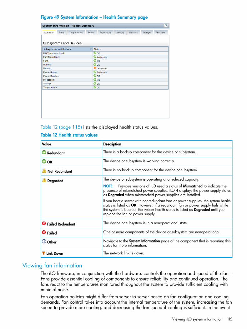
Figure 49 System Information – Health Summary page
Table 12 (page 115) lists the displayed health status values.
Table 12 Health status values
DescriptionValue
There is a backup component for the device or subsystem.Redundant
The device or subsystem is working correctly.OK
There is no backup component for the device or subsystem.Not Redundant
The device or subsystem is operating at a reduced capacity.DegradedNOTE: Previous versions of iLO used a status of Mismatched to indicate thepresence of mismatched power supplies. iLO 4 displays the power supply statusas Degraded when mismatched power supplies are installed.If you boot a server with nonredundant fans or power supplies, the system healthstatus is listed as OK. However, if a redundant fan or power supply fails whilethe system is booted, the system health status is listed as Degraded until youreplace the fan or power supply.
The device or subsystem is in a nonoperational state.Failed Redundant
One or more components of the device or subsystem are nonoperational.Failed
Navigate to the System Information page of the component that is reporting thisstatus for more information.
Other
The network link is down.Link Down
Viewing fan informationThe iLO firmware, in conjunction with the hardware, controls the operation and speed of the fans.Fans provide essential cooling of components to ensure reliability and continued operation. Thefans react to the temperatures monitored throughout the system to provide sufficient cooling withminimal noise.Fan operation policies might differ from server to server based on fan configuration and coolingdemands. Fan control takes into account the internal temperature of the system, increasing the fanspeed to provide more cooling, and decreasing the fan speed if cooling is sufficient. In the event
Viewing iLO system information 115
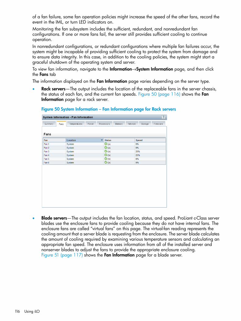
of a fan failure, some fan operation policies might increase the speed of the other fans, record theevent in the IML, or turn LED indicators on.Monitoring the fan subsystem includes the sufficient, redundant, and nonredundant fanconfigurations. If one or more fans fail, the server still provides sufficient cooling to continueoperation.In nonredundant configurations, or redundant configurations where multiple fan failures occur, thesystem might be incapable of providing sufficient cooling to protect the system from damage andto ensure data integrity. In this case, in addition to the cooling policies, the system might start agraceful shutdown of the operating system and server.To view fan information, navigate to the Information→System Information page, and then clickthe Fans tabThe information displayed on the Fan Information page varies depending on the server type.
• Rack servers—The output includes the location of the replaceable fans in the server chassis,the status of each fan, and the current fan speeds. Figure 50 (page 116) shows the FanInformation page for a rack server.
Figure 50 System Information – Fan Information page for Rack servers
• Blade servers—The output includes the fan location, status, and speed. ProLiant c-Class serverblades use the enclosure fans to provide cooling because they do not have internal fans. Theenclosure fans are called “virtual fans” on this page. The virtual-fan reading represents thecooling amount that a server blade is requesting from the enclosure. The server blade calculatesthe amount of cooling required by examining various temperature sensors and calculating anappropriate fan speed. The enclosure uses information from all of the installed server andnonserver blades to adjust the fans to provide the appropriate enclosure cooling.Figure 51 (page 117) shows the Fan Information page for a blade server.
116 Using iLO
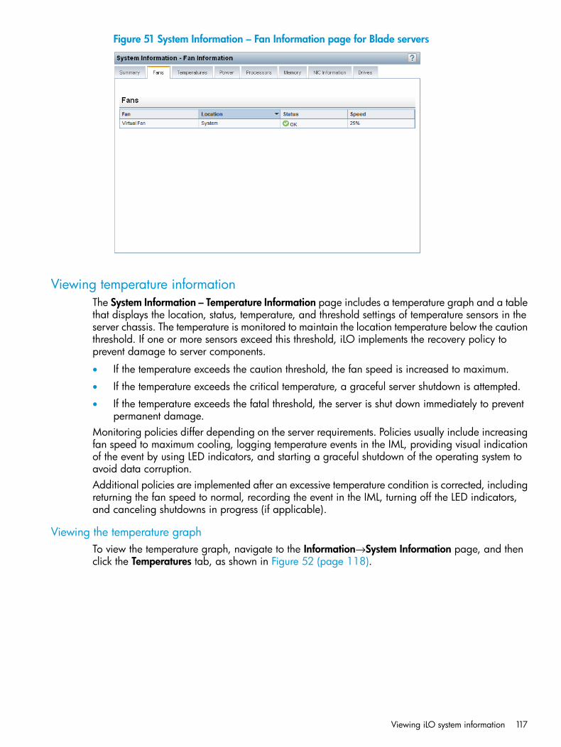
Figure 51 System Information – Fan Information page for Blade servers
Viewing temperature informationThe System Information – Temperature Information page includes a temperature graph and a tablethat displays the location, status, temperature, and threshold settings of temperature sensors in theserver chassis. The temperature is monitored to maintain the location temperature below the cautionthreshold. If one or more sensors exceed this threshold, iLO implements the recovery policy toprevent damage to server components.
• If the temperature exceeds the caution threshold, the fan speed is increased to maximum.
• If the temperature exceeds the critical temperature, a graceful server shutdown is attempted.
• If the temperature exceeds the fatal threshold, the server is shut down immediately to preventpermanent damage.
Monitoring policies differ depending on the server requirements. Policies usually include increasingfan speed to maximum cooling, logging temperature events in the IML, providing visual indicationof the event by using LED indicators, and starting a graceful shutdown of the operating system toavoid data corruption.Additional policies are implemented after an excessive temperature condition is corrected, includingreturning the fan speed to normal, recording the event in the IML, turning off the LED indicators,and canceling shutdowns in progress (if applicable).
Viewing the temperature graphTo view the temperature graph, navigate to the Information→System Information page, and thenclick the Temperatures tab, as shown in Figure 52 (page 118).
Viewing iLO system information 117

Figure 52 Viewing the temperature graph
Viewing the graph:
• The circles on the graph correspond to the sensors listed in the Sensor Data table.
• Move the mouse over a circle on the graph to view the sensor ID, reading, and status. Forexample, Figure 52 (page 118) shows sensor 01-Inlet Ambient on the temperature graph andin the Sensor Data table.
• The color on the graph is a gradient that ranges from green to red. Green represents atemperature of 0°C and red represents the critical threshold. As the temperature of a sensorincreases, the graph color changes from green to amber, and then to red when the temperatureapproaches the critical threshold.
Customizing the graph display:
• Select the 3D check box to display a three-dimensional graph.
• Clear the 3D check box to display a two-dimensional graph.
• Select Front View or Back View to display the sensors located at the front or back of the server.
Viewing temperature sensor dataTo view temperature sensor data, navigate to the Information→System Information page, and thenclick the Temperatures tab, as shown in Figure 53 (page 119).When temperatures are displayed in Celsius, you can click the Show values in Fahrenheit buttonto change the display to Fahrenheit. When temperatures are displayed in Fahrenheit, you canclick the Show values in Celsius button to change the display to Celsius.By default, missing sensors are hidden. To view the missing sensors, click the show missing sensorstext. When missing sensors are displayed, click the hide missing sensors text to hide them.
118 Using iLO
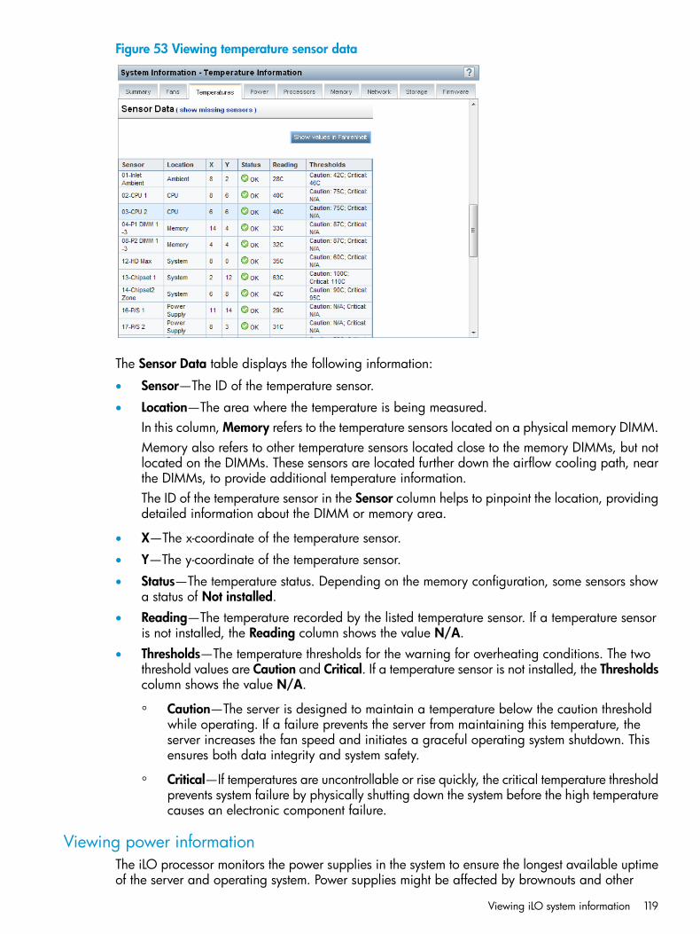
Figure 53 Viewing temperature sensor data
The Sensor Data table displays the following information:
• Sensor—The ID of the temperature sensor.
• Location—The area where the temperature is being measured.In this column, Memory refers to the temperature sensors located on a physical memory DIMM.Memory also refers to other temperature sensors located close to the memory DIMMs, but notlocated on the DIMMs. These sensors are located further down the airflow cooling path, nearthe DIMMs, to provide additional temperature information.The ID of the temperature sensor in the Sensor column helps to pinpoint the location, providingdetailed information about the DIMM or memory area.
• X—The x-coordinate of the temperature sensor.
• Y—The y-coordinate of the temperature sensor.
• Status—The temperature status. Depending on the memory configuration, some sensors showa status of Not installed.
• Reading—The temperature recorded by the listed temperature sensor. If a temperature sensoris not installed, the Reading column shows the value N/A.
• Thresholds—The temperature thresholds for the warning for overheating conditions. The twothreshold values are Caution and Critical. If a temperature sensor is not installed, the Thresholdscolumn shows the value N/A.
◦ Caution—The server is designed to maintain a temperature below the caution thresholdwhile operating. If a failure prevents the server from maintaining this temperature, theserver increases the fan speed and initiates a graceful operating system shutdown. Thisensures both data integrity and system safety.
◦ Critical—If temperatures are uncontrollable or rise quickly, the critical temperature thresholdprevents system failure by physically shutting down the system before the high temperaturecauses an electronic component failure.
Viewing power informationThe iLO processor monitors the power supplies in the system to ensure the longest available uptimeof the server and operating system. Power supplies might be affected by brownouts and other
Viewing iLO system information 119
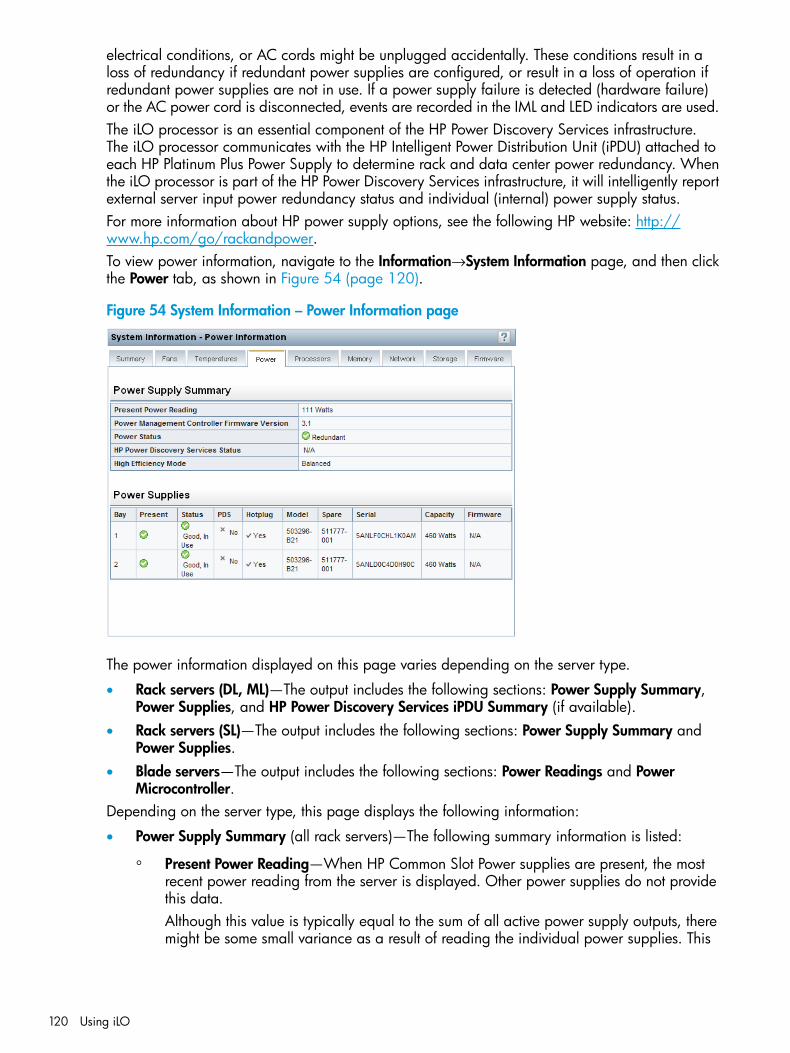
electrical conditions, or AC cords might be unplugged accidentally. These conditions result in aloss of redundancy if redundant power supplies are configured, or result in a loss of operation ifredundant power supplies are not in use. If a power supply failure is detected (hardware failure)or the AC power cord is disconnected, events are recorded in the IML and LED indicators are used.The iLO processor is an essential component of the HP Power Discovery Services infrastructure.The iLO processor communicates with the HP Intelligent Power Distribution Unit (iPDU) attached toeach HP Platinum Plus Power Supply to determine rack and data center power redundancy. Whenthe iLO processor is part of the HP Power Discovery Services infrastructure, it will intelligently reportexternal server input power redundancy status and individual (internal) power supply status.For more information about HP power supply options, see the following HP website: http://www.hp.com/go/rackandpower.To view power information, navigate to the Information→System Information page, and then clickthe Power tab, as shown in Figure 54 (page 120).
Figure 54 System Information – Power Information page
The power information displayed on this page varies depending on the server type.
• Rack servers (DL, ML)—The output includes the following sections: Power Supply Summary,Power Supplies, and HP Power Discovery Services iPDU Summary (if available).
• Rack servers (SL)—The output includes the following sections: Power Supply Summary andPower Supplies.
• Blade servers—The output includes the following sections: Power Readings and PowerMicrocontroller.
Depending on the server type, this page displays the following information:
• Power Supply Summary (all rack servers)—The following summary information is listed:
Present Power Reading—When HP Common Slot Power supplies are present, the mostrecent power reading from the server is displayed. Other power supplies do not providethis data.Although this value is typically equal to the sum of all active power supply outputs, theremight be some small variance as a result of reading the individual power supplies. This
◦
120 Using iLO

value is a guideline value and is not as accurate as the values presented on the PowerManagement pages. For more information, see “Viewing server power usage” (page 180).
◦ Power Management Controller Firmware Version—The firmware version of the powermanagement controller. The server must be powered on for iLO to determine the firmwareversion. This feature is not available on all servers.
◦ Power Status—Indicates the overall status of the power supplied to the server.If the server power supplies are connected to a nonintelligent power source, this boxdisplays the status of the internal server power supplies.
–
– If the server power supplies are connected to HP Discovery Services through an HPiPDU, this box displays the status of the power supplied to the internal server powersupplies.
Possible values follow:
– Redundant—Indicates whether the power supplies are in a redundant state. If HPPower Discovery Services is integrated into the infrastructure, the Power Status boxindicates whether the externally supplied power to the internal power supplies isredundant.
– Not Redundant—Indicates that at least one of the power supplies or iPDUs (in thecase of HP Power Discovery Services) is not supplying power to the server. The mostcommon reason for this status is a loss of input power to the power supply. Anotherreason for this status is a configuration with multiple power supplies connected tothe same iPDU. In this case, the individual power supply status is Good, In Use, butthe Power Status value is Not Redundant because the loss of input power to the iPDUwould lead to a total loss of power to the server.
– N/A—This server does not have redundant power supply capability.
◦ HP Power Discovery Services Status—Possible values follow:Redundant—The server is configured for a redundant iPDU configuration.–
– Not Redundant—There are not sufficient iPDUs to support redundancy, or the server’spower supplies are connected to the same iPDU.
– N/A—No iPDUs were discovered.
NOTE: When the iLO processor or the server is reset, the iPDU discovery process cantake a few minutes to complete.
◦ High Efficiency Mode—The redundant power supply mode that will be used if redundantpower supplies are configured.High Efficiency Mode improves the power efficiency of the system by placing the secondarypower supplies in standby mode. When the secondary power supplies are in standbymode, primary power provides all DC power to the system. The power supplies are moreefficient (more DC output watts for each watt of AC input) at higher output levels, andthe overall power efficiency improves.High Efficiency Mode does not affect power redundancy. If the primary power suppliesfail, the secondary power supplies immediately begin supplying DC power to the system,preventing any downtime. You can configure redundant power supply modes only throughthe system RBSU. You cannot modify these settings through iLO. For more information,see the HP ROM-Based Setup Utility User Guide.
NOTE: If High Efficiency Mode is in an unsupported mode, you might experiencedecreased efficiency of your power supplies.
Viewing iLO system information 121
The redundant power supply modes follow:
– N/A—Not applicable.
– Balanced Mode—Delivers power equally across all installed power supplies.
– High Efficiency Mode (Auto)—Delivers full power to one of the power supplies, andplaces the other power supplies on standby at a lower power-usage level. Asemi-random distribution is achieved, because the Auto option chooses between theodd or even power supply based on the server serial number.
– High Efficiency Mode (Even Supply Standby)—Delivers full power to the odd-numberedpower supplies, and places the even-numbered power supplies on standby at a lowerpower-usage level.
– High Efficiency Mode (Odd Supply Standby)—Delivers full power to the even-numberedpower supplies, and places the odd-numbered power supplies on standby at a lowerpower-usage level.
– Not Supported—The installed power supplies do not support High Efficiency Mode.
• Power Supplies (ML and DL servers only)—The following information is displayed for eachpower supply.
◦ Bay—The bay number of the power supply.
◦ Present—Whether a power supply is installed.
◦ Status—The status of the power supply.
◦ PDS—Whether the installed power supply is enabled for HP Power Discovery Services.PDS is an enhancement to the HP iPDU technology. If the server power supply is connectedto an iPDU, an additional summary table on this page displays the linked iPDUs. Formore information about HP Power Discovery Services and iPDUs, see http://www.hp.com/go/ipd.
NOTE: Some power supplies do not provide information for all of the values on thispage. If a power supply does not provide information for a value, N/A is displayed.
◦ Hotplug—Whether the power supply bay supports swapping the power supply when theserver is powered on. If the value is Yes, and the power supplies are redundant, thepower supply can be removed or replaced when the server is powered on.
◦ Model—The model number of the power supply.
◦ Spare—The part number of the spare power supply.
◦ Serial—The serial number of the power supply.
◦ Capacity—The capacity of the power supply (watts).
◦ Firmware—The installed power supply firmware.
• Power Supplies (SL servers only)—The name, location, and status of the installed powersupplies.
◦ OK—Indicates that the power supply is installed and operational.
◦ Not Installed—Indicates that the power supply is not installed. Power is not redundant.
122 Using iLO
◦ Failed—Indicates that the power supply is not functioning. Make sure that the power cordis plugged in.
◦ Mismatched Supply Types—Indicates that multiple types of power supplies are installed,and that this power supply is not in use. If mismatched power supply types are installed,only one type is used. For correct operation at the power subsystem, make sure that thepower supplies are the same type, wattage, and part number.
• HP Power Discovery Services iPDU Summary (ML and DL servers only)—This section is displayedon the System Information – Power Information page only if the server power supplies areconnected to an iPDU.For more information about the state-of-the-art technology features that HP brings to the IntelligentData Center, see the following website: http://www.hp.com/go/ipd.After iLO is reset, or when the iPDU is attached, it takes approximately 2 minutes for the iLOweb interface to display the HP Power Discovery Services iPDU Summary table. This delay iscaused by the iPDU discovery process. The following information is displayed in the table:
◦ Bay—The power supply bay number.
◦ Status—The overall communication-link status and rack input power redundancy, asdetermined by the iPDU. Possible values follow:– iPDU Redundant—This Good status indicates that the server is connected to at least
two different iPDUs.– iPDU Not Redundant—This Caution status indicates that the server is not connected
to at least two different iPDUs. Typically, this status is displayed when one of thefollowing conditions occurs:– An iPDU link is not established for all power supplies.
– Two or more power supplies are connected to the same iPDU.
– The iPDU MAC Address and iPDU Serial Number are identical for power supplieswhose input power comes from the same iPDU. If one power supply is waitingfor a connection to be established, the iPDU is listed as Not Redundant.
– Waiting for connection—This Informational status indicates one or more of thefollowing conditions:– The wrong power cord was used to connect the power supply to the iPDU.
– The iPDU and the iLO processor are in the process of connecting. This processcan take up to 2 minutes after the iLO processor or the iPDU is reset.
– The iPDU module does not have a network (or IP) address.
◦ Part Number—The iPDU part number.
◦ Serial—The iPDU serial number.
◦ MAC Address—The MAC address of the iPDU network port. This box helps you to uniquelyidentify each connected iPDU, because each iPDU has a unique MAC address.
◦ iPDU Link—The iPDU HTTP address (if available). Click the link in this column to open theHP Intelligent Modular PDU web interface.
Viewing iLO system information 123
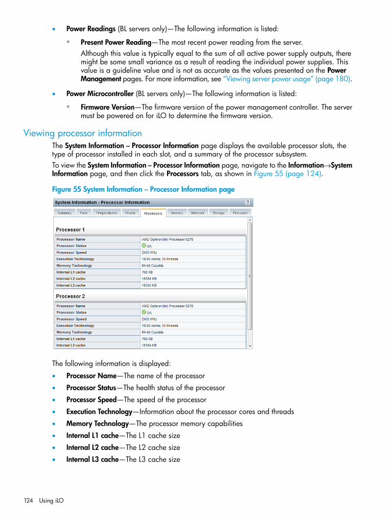
• Power Readings (BL servers only)—The following information is listed:
◦ Present Power Reading—The most recent power reading from the server.Although this value is typically equal to the sum of all active power supply outputs, theremight be some small variance as a result of reading the individual power supplies. Thisvalue is a guideline value and is not as accurate as the values presented on the PowerManagement pages. For more information, see “Viewing server power usage” (page 180).
• Power Microcontroller (BL servers only)—The following information is listed:
◦ Firmware Version—The firmware version of the power management controller. The servermust be powered on for iLO to determine the firmware version.
Viewing processor informationThe System Information – Processor Information page displays the available processor slots, thetype of processor installed in each slot, and a summary of the processor subsystem.To view the System Information – Processor Information page, navigate to the Information→SystemInformation page, and then click the Processors tab, as shown in Figure 55 (page 124).
Figure 55 System Information – Processor Information page
The following information is displayed:
• Processor Name—The name of the processor
• Processor Status—The health status of the processor
• Processor Speed—The speed of the processor
• Execution Technology—Information about the processor cores and threads
• Memory Technology—The processor memory capabilities
• Internal L1 cache—The L1 cache size
• Internal L2 cache—The L2 cache size
• Internal L3 cache—The L3 cache size
124 Using iLO
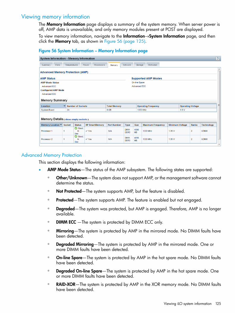
Viewing memory informationThe Memory Information page displays a summary of the system memory. When server power isoff, AMP data is unavailable, and only memory modules present at POST are displayed.To view memory information, navigate to the Information→System Information page, and thenclick the Memory tab, as shown in Figure 56 (page 125).
Figure 56 System Information – Memory Information page
Advanced Memory ProtectionThis section displays the following information:
• AMP Mode Status—The status of the AMP subsystem. The following states are supported:
Other/Unknown—The system does not support AMP, or the management software cannotdetermine the status.
◦
◦ Not Protected—The system supports AMP, but the feature is disabled.
◦ Protected—The system supports AMP. The feature is enabled but not engaged.
◦ Degraded—The system was protected, but AMP is engaged. Therefore, AMP is no longeravailable.
◦ DIMM ECC —The system is protected by DIMM ECC only.
◦ Mirroring—The system is protected by AMP in the mirrored mode. No DIMM faults havebeen detected.
◦ Degraded Mirroring—The system is protected by AMP in the mirrored mode. One ormore DIMM faults have been detected.
◦ On-line Spare—The system is protected by AMP in the hot spare mode. No DIMM faultshave been detected.
◦ Degraded On-line Spare—The system is protected by AMP in the hot spare mode. Oneor more DIMM faults have been detected.
◦ RAID-XOR—The system is protected by AMP in the XOR memory mode. No DIMM faultshave been detected.
Viewing iLO system information 125
◦ Degraded RAID-XOR—The system is protected by AMP in the XOR memory mode. Oneor more DIMM faults have been detected.
◦ Advanced ECC—The system is protected by AMP in the Advanced ECC mode.
◦ Degraded Advanced ECC—The system is protected by AMP in the Advanced ECC mode.One or more DIMM faults have been detected.
◦ LockStep—The system is protected by AMP in the LockStep mode.
◦ Degraded LockStep—The system is protected by AMP in the LockStep mode. One or moreDIMM faults have been detected.
• Configured AMP Mode—The active AMP mode. The following modes are supported:
None/Unknown—The management software cannot determine the AMP fault tolerance,or the system is not configured for AMP.
◦
◦ On-line Spare—A single spare bank of memory is set aside at boot time. If enough ECCerrors occur, the spare memory is activated and the memory that is experiencing theerrors is disabled.
◦ Mirroring—The system is configured for mirrored memory protection. All memory banksare duplicated in mirrored memory, as opposed to only one for online spare memory. Ifenough ECC errors occur, the spare memory is activated and the memory that isexperiencing the errors is disabled.
◦ RAID-XOR—The system is configured for AMP with the XOR engine.
◦ Advanced ECC—The system is configured for AMP with the Advanced ECC engine.
◦ LockStep—The system is configured for AMP with the LockStep engine.
• Supported AMP Modes—The following modes are supported:
RAID-XOR—The system can be configured for AMP using the XOR engine.◦◦ Dual Board Mirroring—The system can be configured for mirrored advanced memory
protection in a dual memory board configuration. The mirrored memory can be swappedwith memory on the same memory board or with memory on the second memory board.
◦ Single Board Mirroring—The system can be configured for mirrored advanced memoryprotection in a single memory board.
◦ Advanced ECC—The system can be configured for Advanced ECC.
◦ Mirroring—The system can be configured for mirrored AMP.
◦ On-line Spare—The system can be configured for online spare AMP.
◦ LockStep—The system can be configured for LockStep AMP.
◦ None—The system cannot be configured for AMP.
126 Using iLO

Memory SummaryThis section shows a summary of the memory installed and operational at POST.
• Location—The slot or processor on which the memory board, cartridge, or riser is installed.Possible values follow:
◦ System Board—There is no separate memory board slot. All DIMMs are installed on themotherboard.
◦ Board Number—There is a memory board slot available. All DIMMs are installed on thememory board.
◦ Processor Number—The processor on which the memory DIMMs are installed.
◦ Riser Number—The riser on which the memory DIMMs are installed.
• Number of Sockets—The number of memory module sockets present on the memory board,cartridge, or riser.
• Total Memory—The size of the memory for this board, cartridge, or riser, including memoryrecognized by the operating system and memory used for spare, mirrored, or XORconfigurations.
• Operating Frequency—The frequency at which the memory on the memory board, cartridge,or riser operates.
• Operating Voltage—The voltage at which the memory on the memory board, cartridge, orriser operates.
Memory DetailsThis section shows the memory modules on the host that are installed and operational at POST.Unpopulated module positions are also listed. Various resilient memory configurations can changethe actual memory inventory from what was sampled at POST. In systems that have a high numberof memory modules, all module positions might not be listed.By default, empty memory slots are hidden. To view the empty memory slots, click the show emptysockets text. When empty memory slots are displayed, click the hide empty sockets text to hidethem.
• Memory Location—The slot or processor on which the memory module is installed.
• Socket—The memory module socket number.
• Status—The memory module status and whether the module is in use.
• HP SmartMemory—Whether the memory module is HP SmartMemory. Possible values are Yesand No. If no memory module is installed, the value N/A is displayed.If the value No is displayed, the listed module is not an HP SmartMemory module. The memorymodule will function, but it has no warranty, and it might not perform as well as an HPSmartMemory module.For more information about HP SmartMemory, see http://www.hp.com/products/memory.
• Part Number—The memory module part number.
NOTE: This value is displayed only for HP SmartMemory modules.
• Type—The type of memory installed. Possible values follow:
Other—Memory type cannot be determined.◦◦ Board—Memory module is permanently mounted (not modular) on a system board or
memory expansion board.
Viewing iLO system information 127
◦ CPQ single width module
◦ CPQ double width module
◦ SIMM
◦ PCMCIA
◦ Compaq-specific
◦ DIMM
◦ Small outline DIMM
◦ RIMM
◦ SRIMM
◦ FB-DIMM
◦ DIMM DDR
◦ DIMM DDR2
◦ DIMM DDR3
◦ FB-DIMM DDR2
◦ FB-DIMM DDR3
◦ N/A—Memory module is not present.
• Size—The size of the memory module, in MB.
• Maximum Frequency—The maximum frequency at which the memory module can operate.
• Minimum Voltage—The minimum voltage at which the memory module can operate.
• Ranks—The number of ranks in the memory module.
• Technology—The memory module technology. Possible values follow:
Unknown—Memory technology cannot be determined.◦◦ N/A—Memory module is not present.
◦ Fast Page
◦ EDO
◦ Burst EDO
◦ Synchronous
◦ RDRAM
◦ RDIMM
◦ UDIMM
◦ LRDIMM
Viewing network informationThe NIC Information page displays read-only information about the integrated NICs.
128 Using iLO
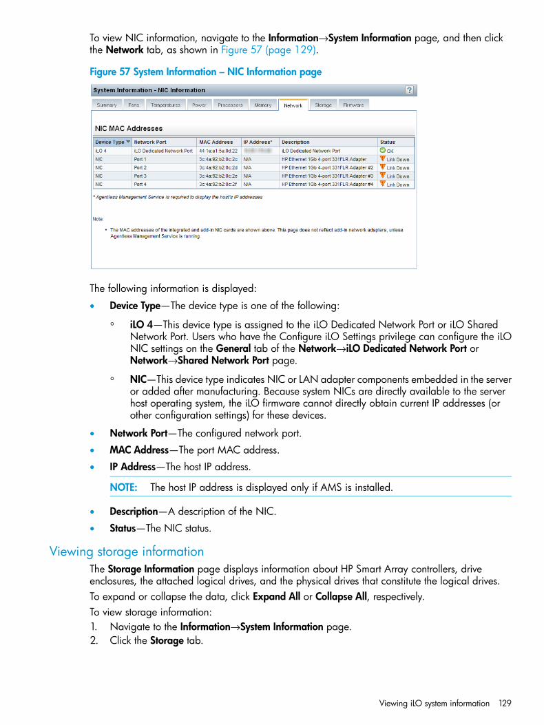
To view NIC information, navigate to the Information→System Information page, and then clickthe Network tab, as shown in Figure 57 (page 129).
Figure 57 System Information – NIC Information page
The following information is displayed:
• Device Type—The device type is one of the following:
iLO 4—This device type is assigned to the iLO Dedicated Network Port or iLO SharedNetwork Port. Users who have the Configure iLO Settings privilege can configure the iLO
◦
NIC settings on the General tab of the Network→iLO Dedicated Network Port orNetwork→Shared Network Port page.
◦ NIC—This device type indicates NIC or LAN adapter components embedded in the serveror added after manufacturing. Because system NICs are directly available to the serverhost operating system, the iLO firmware cannot directly obtain current IP addresses (orother configuration settings) for these devices.
• Network Port—The configured network port.
• MAC Address—The port MAC address.
• IP Address—The host IP address.
NOTE: The host IP address is displayed only if AMS is installed.
• Description—A description of the NIC.
• Status—The NIC status.
Viewing storage informationThe Storage Information page displays information about HP Smart Array controllers, driveenclosures, the attached logical drives, and the physical drives that constitute the logical drives.To expand or collapse the data, click Expand All or Collapse All, respectively.To view storage information:1. Navigate to the Information→System Information page.2. Click the Storage tab.
Viewing iLO system information 129
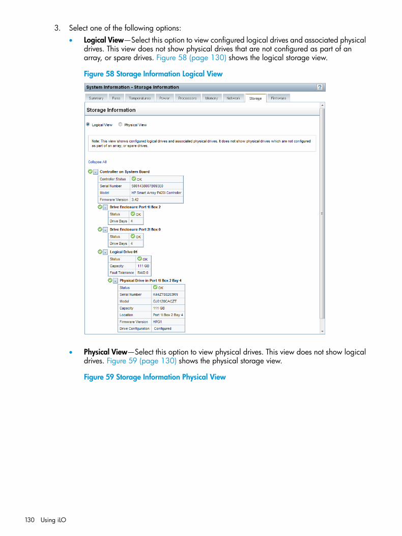
3. Select one of the following options:• Logical View—Select this option to view configured logical drives and associated physical
drives. This view does not show physical drives that are not configured as part of anarray, or spare drives. Figure 58 (page 130) shows the logical storage view.
Figure 58 Storage Information Logical View
• Physical View—Select this option to view physical drives. This view does not show logicaldrives. Figure 59 (page 130) shows the physical storage view.
Figure 59 Storage Information Physical View
130 Using iLO
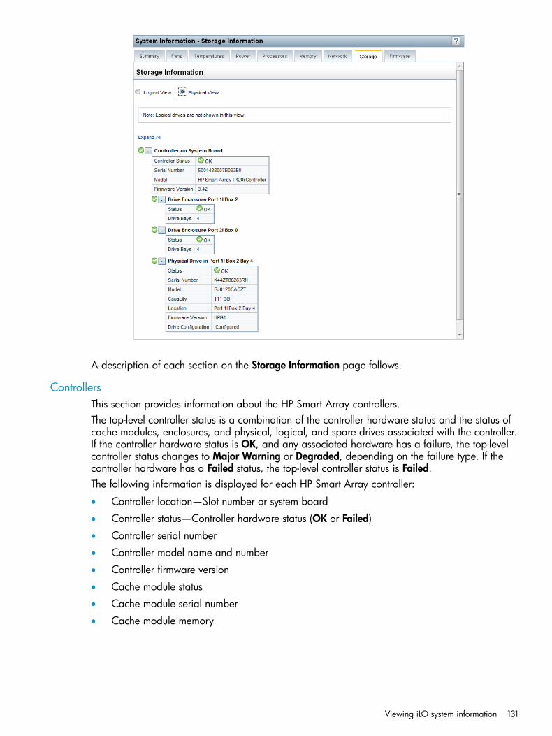
A description of each section on the Storage Information page follows.
ControllersThis section provides information about the HP Smart Array controllers.The top-level controller status is a combination of the controller hardware status and the status ofcache modules, enclosures, and physical, logical, and spare drives associated with the controller.If the controller hardware status is OK, and any associated hardware has a failure, the top-levelcontroller status changes to Major Warning or Degraded, depending on the failure type. If thecontroller hardware has a Failed status, the top-level controller status is Failed.The following information is displayed for each HP Smart Array controller:
• Controller location—Slot number or system board
• Controller status—Controller hardware status (OK or Failed)
• Controller serial number
• Controller model name and number
• Controller firmware version
• Cache module status
• Cache module serial number
• Cache module memory
Viewing iLO system information 131
Drive EnclosuresThis section provides the following information about the drive enclosures attached to an HP SmartArray controller:
• Enclosure port and box numbers
• Enclosure status
• Number of drive bays
• Serial number
• Model number
• Firmware versionSome enclosures do not have all of the listed properties, and some storage configurations do nothave drive enclosures.
Logical DrivesThis section is available when the Logical View option is selected on the System Information –Storage Information page. The following information is listed for the logical drives attached to anHP Smart Array controller:
• Logical drive number
• Logical drive status
• Logical drive capacity
• Fault tolerance
NOTE: Logical drives must be configured through the HP Smart Storage Administrator softwarebefore they can be displayed on the System Information – Storage Information page. For moreinformation, see the HP Smart Storage Administrator documentation.
Physical DrivesThe information listed in this section depends on whether the Logical View or Physical View optionis selected. When using Logical View, physical drives that are configured as part of an array arelisted. When using Physical View, all physical drives are listed.When a physical drive has a Failed status, this status does not affect the overall storage healthstatus. Only logical drives affect the storage health status.The following information is listed for the physical drives attached to an HP Smart Array controller:
• Physical drive port, box, and bay numbers
• Physical drive status
• Physical drive serial number
• Physical drive model number
• Physical drive capacity
• Physical drive location
• Physical drive firmware version
• Physical drive configuration
Viewing firmware informationThe Firmware Information page displays firmware information for various server components. Foreach component, the page shows the firmware name and the installed firmware version.
132 Using iLO
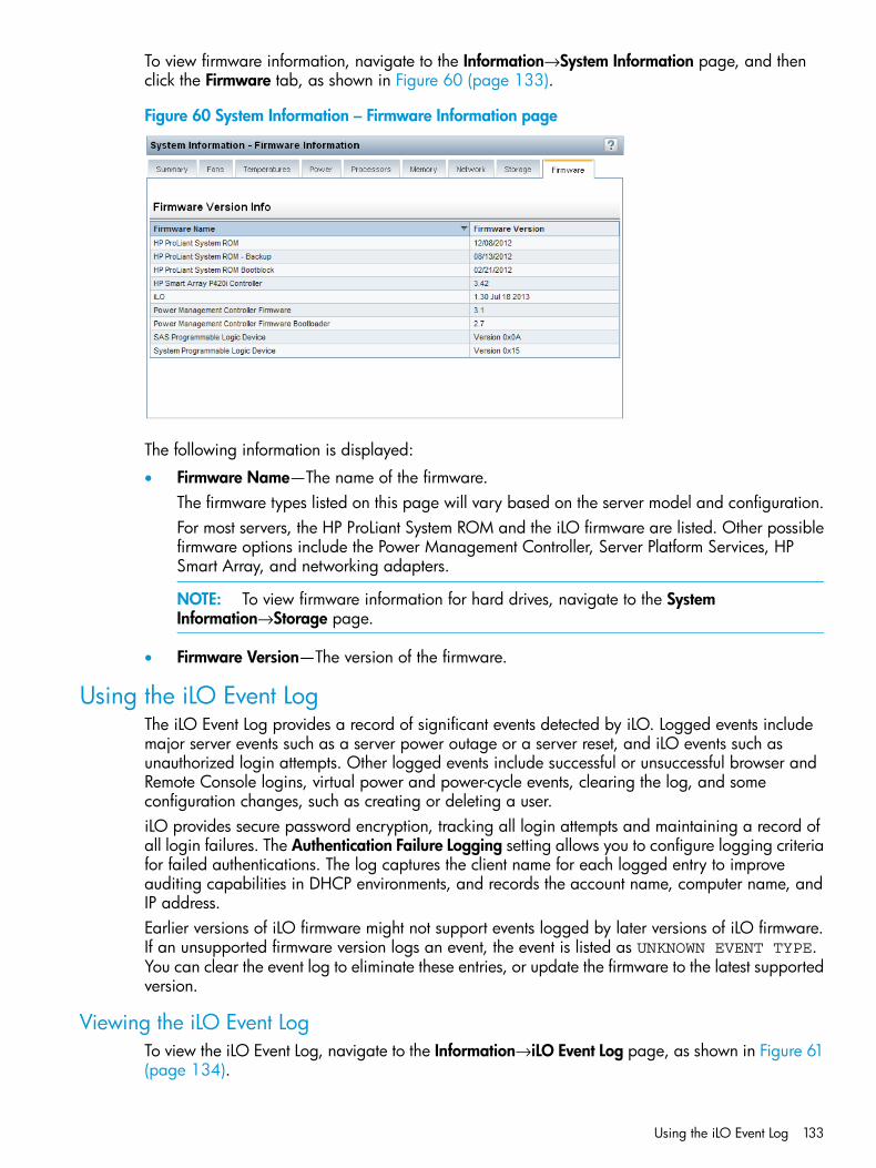
To view firmware information, navigate to the Information→System Information page, and thenclick the Firmware tab, as shown in Figure 60 (page 133).
Figure 60 System Information – Firmware Information page
The following information is displayed:
• Firmware Name—The name of the firmware.The firmware types listed on this page will vary based on the server model and configuration.For most servers, the HP ProLiant System ROM and the iLO firmware are listed. Other possiblefirmware options include the Power Management Controller, Server Platform Services, HPSmart Array, and networking adapters.
NOTE: To view firmware information for hard drives, navigate to the SystemInformation→Storage page.
• Firmware Version—The version of the firmware.
Using the iLO Event LogThe iLO Event Log provides a record of significant events detected by iLO. Logged events includemajor server events such as a server power outage or a server reset, and iLO events such asunauthorized login attempts. Other logged events include successful or unsuccessful browser andRemote Console logins, virtual power and power-cycle events, clearing the log, and someconfiguration changes, such as creating or deleting a user.iLO provides secure password encryption, tracking all login attempts and maintaining a record ofall login failures. The Authentication Failure Logging setting allows you to configure logging criteriafor failed authentications. The log captures the client name for each logged entry to improveauditing capabilities in DHCP environments, and records the account name, computer name, andIP address.Earlier versions of iLO firmware might not support events logged by later versions of iLO firmware.If an unsupported firmware version logs an event, the event is listed as UNKNOWN EVENT TYPE.You can clear the event log to eliminate these entries, or update the firmware to the latest supportedversion.
Viewing the iLO Event LogTo view the iLO Event Log, navigate to the Information→iLO Event Log page, as shown in Figure 61(page 134).
Using the iLO Event Log 133
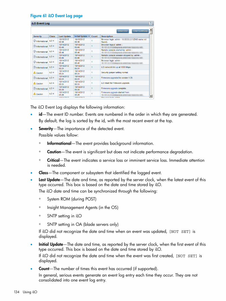
Figure 61 iLO Event Log page
The iLO Event Log displays the following information:
• id—The event ID number. Events are numbered in the order in which they are generated.By default, the log is sorted by the id, with the most recent event at the top.
• Severity—The importance of the detected event.Possible values follow:
◦ Informational—The event provides background information.
◦ Caution—The event is significant but does not indicate performance degradation.
◦ Critical—The event indicates a service loss or imminent service loss. Immediate attentionis needed.
• Class—The component or subsystem that identified the logged event.
• Last Update—The date and time, as reported by the server clock, when the latest event of thistype occurred. This box is based on the date and time stored by iLO.The iLO date and time can be synchronized through the following:
◦ System ROM (during POST)
◦ Insight Management Agents (in the OS)
◦ SNTP setting in iLO
◦ SNTP setting in OA (blade servers only)
If iLO did not recognize the date and time when an event was updated, [NOT SET] isdisplayed.
• Initial Update—The date and time, as reported by the server clock, when the first event of thistype occurred. This box is based on the date and time stored by iLO.If iLO did not recognize the date and time when the event was first created, [NOT SET] isdisplayed.
• Count—The number of times this event has occurred (if supported).In general, serious events generate an event log entry each time they occur. They are notconsolidated into one event log entry.
134 Using iLO
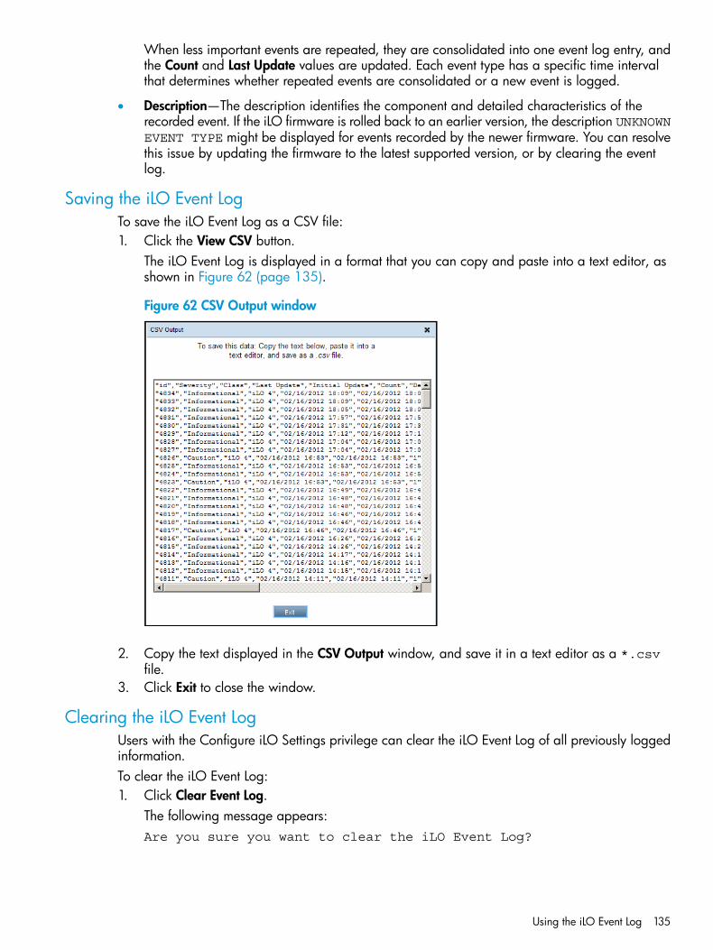
When less important events are repeated, they are consolidated into one event log entry, andthe Count and Last Update values are updated. Each event type has a specific time intervalthat determines whether repeated events are consolidated or a new event is logged.
• Description—The description identifies the component and detailed characteristics of therecorded event. If the iLO firmware is rolled back to an earlier version, the description UNKNOWNEVENT TYPE might be displayed for events recorded by the newer firmware. You can resolvethis issue by updating the firmware to the latest supported version, or by clearing the eventlog.
Saving the iLO Event LogTo save the iLO Event Log as a CSV file:1. Click the View CSV button.
The iLO Event Log is displayed in a format that you can copy and paste into a text editor, asshown in Figure 62 (page 135).
Figure 62 CSV Output window
2. Copy the text displayed in the CSV Output window, and save it in a text editor as a *.csvfile.
3. Click Exit to close the window.
Clearing the iLO Event LogUsers with the Configure iLO Settings privilege can clear the iLO Event Log of all previously loggedinformation.To clear the iLO Event Log:1. Click Clear Event Log.
The following message appears:Are you sure you want to clear the iLO Event Log?
Using the iLO Event Log 135
2. Click OK.The following event is recorded:Event log cleared by <user name>.
Using the Integrated Management LogThe IML provides a record of historical events that have occurred on the server. Events are generatedby the system ROM and by services such as the iLO health driver. Logged events include allserver-specific events recorded by the system health driver, including operating system informationand ROM-based POST codes.Entries in the IML can help you diagnose issues or identify potential issues. Preventative actionmight help to avoid disruption of service. iLO manages the IML, which you can access through asupported browser, even when the server is off. The ability to view the log when the server is offcan be helpful when troubleshooting remote host server issues.Examples of the types of information that the iLO processor records in the IML follow:
• Fan inserted
• Fan removed
• Fan failure
• Fan degraded
• Fan repaired
• Fan redundancy lost
• Fans redundant
• Power supply inserted
• Power supply removed
• Power supply failure
• Power supplies redundancy lost
• Power supplies redundant
• Temperature over threshold
• Temperature normal
• Automatic shutdown started
• Automatic shutdown canceled
• Drive failure
Viewing the IMLTo view the IML, navigate to the Information→Integrated Management Log page, as shown inFigure 63 (page 137).
136 Using iLO
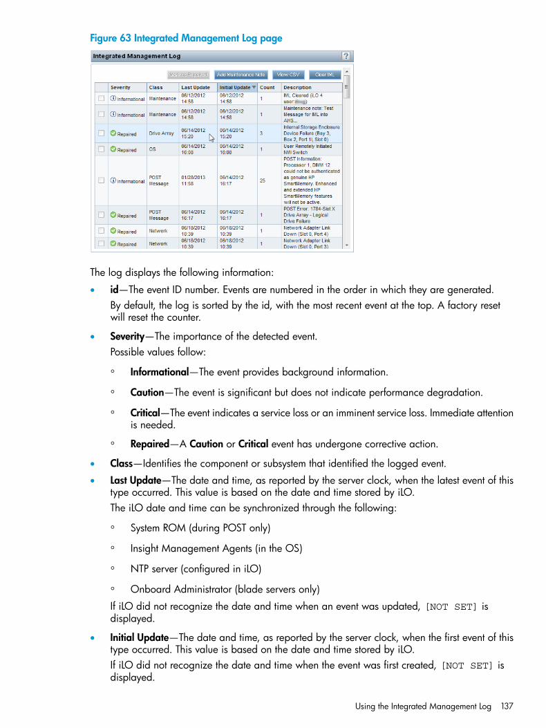
Figure 63 Integrated Management Log page
The log displays the following information:
• id—The event ID number. Events are numbered in the order in which they are generated.By default, the log is sorted by the id, with the most recent event at the top. A factory resetwill reset the counter.
• Severity—The importance of the detected event.Possible values follow:
◦ Informational—The event provides background information.
◦ Caution—The event is significant but does not indicate performance degradation.
◦ Critical—The event indicates a service loss or an imminent service loss. Immediate attentionis needed.
◦ Repaired—A Caution or Critical event has undergone corrective action.
• Class—Identifies the component or subsystem that identified the logged event.
• Last Update—The date and time, as reported by the server clock, when the latest event of thistype occurred. This value is based on the date and time stored by iLO.The iLO date and time can be synchronized through the following:
◦ System ROM (during POST only)
◦ Insight Management Agents (in the OS)
◦ NTP server (configured in iLO)
◦ Onboard Administrator (blade servers only)
If iLO did not recognize the date and time when an event was updated, [NOT SET] isdisplayed.
• Initial Update—The date and time, as reported by the server clock, when the first event of thistype occurred. This value is based on the date and time stored by iLO.If iLO did not recognize the date and time when the event was first created, [NOT SET] isdisplayed.
Using the Integrated Management Log 137
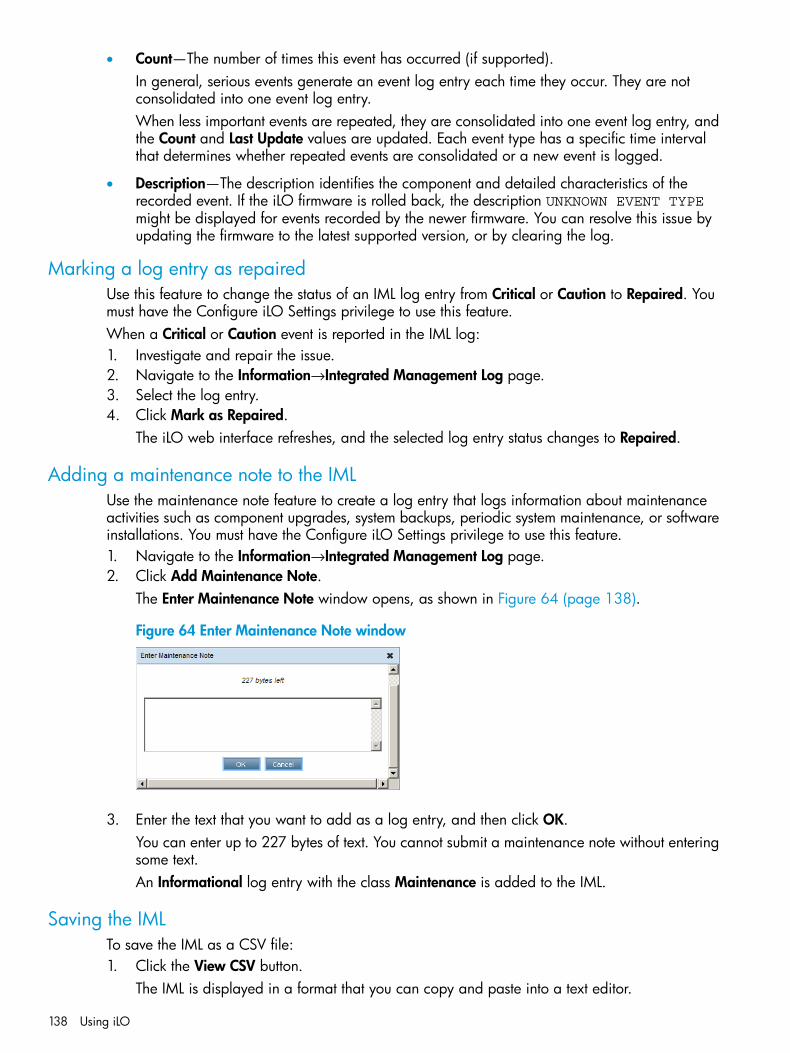
• Count—The number of times this event has occurred (if supported).In general, serious events generate an event log entry each time they occur. They are notconsolidated into one event log entry.When less important events are repeated, they are consolidated into one event log entry, andthe Count and Last Update values are updated. Each event type has a specific time intervalthat determines whether repeated events are consolidated or a new event is logged.
• Description—The description identifies the component and detailed characteristics of therecorded event. If the iLO firmware is rolled back, the description UNKNOWN EVENT TYPEmight be displayed for events recorded by the newer firmware. You can resolve this issue byupdating the firmware to the latest supported version, or by clearing the log.
Marking a log entry as repairedUse this feature to change the status of an IML log entry from Critical or Caution to Repaired. Youmust have the Configure iLO Settings privilege to use this feature.When a Critical or Caution event is reported in the IML log:1. Investigate and repair the issue.2. Navigate to the Information→Integrated Management Log page.3. Select the log entry.4. Click Mark as Repaired.
The iLO web interface refreshes, and the selected log entry status changes to Repaired.
Adding a maintenance note to the IMLUse the maintenance note feature to create a log entry that logs information about maintenanceactivities such as component upgrades, system backups, periodic system maintenance, or softwareinstallations. You must have the Configure iLO Settings privilege to use this feature.1. Navigate to the Information→Integrated Management Log page.2. Click Add Maintenance Note.
The Enter Maintenance Note window opens, as shown in Figure 64 (page 138).
Figure 64 Enter Maintenance Note window
3. Enter the text that you want to add as a log entry, and then click OK.You can enter up to 227 bytes of text. You cannot submit a maintenance note without enteringsome text.An Informational log entry with the class Maintenance is added to the IML.
Saving the IMLTo save the IML as a CSV file:1. Click the View CSV button.
The IML is displayed in a format that you can copy and paste into a text editor.
138 Using iLO

2. Copy the text displayed in the CSV Output window, and save it in a text editor as a *.csvfile.
3. Click Exit to close the window.
Clearing the IMLTo clear the IML of all previously logged information:1. Click Clear IML.
The following message appears:Are you sure you want to clear the Integrated Management Log?
2. To confirm that you want to clear the IML, click OK.The following event is recorded:IML Cleared by <user name>.
You can also clear the IML from the server HP System Management Homepage.
Using the HP Active Health SystemThe HP Active Health System monitors and records changes in the server hardware and systemconfiguration. It assists in diagnosing problems and delivering rapid resolution when system failuresoccur. HP Active Health System does not collect information about your operations, finances,customers, employees, partners, or data center (for example, IP addresses, host names, user names,and passwords).By downloading and sending the Active Health System data to HP, you agree to have HP use thedata for analysis, technical resolution, and quality improvements. The data that is collected ismanaged according to the HP Privacy Statement, available at http://www.hp.com/go/privacy.Examples of data that is collected follow:
• Server model
• Serial number
• Processor model and speed
• Storage capacity and speed
• Memory capacity and speed
• Firmware/BIOS
NOTE: The HP Active Health System does not parse or change operating system data fromthird-party error event log activities (for example, content created or passed through the operatingsystem).
The Active Health System log holds up to 1 GB of data. When this limit is reached, new dataoverwrites the oldest data in the log.You can download the Active Health System log manually and send it to HP. To download thelog, use iLO, Intelligent Provisioning, or the Active Health System download CLI tool. For moreinformation, see “Downloading the Active Health System log for a date range” (page 139), the HPIntelligent Provisioning User Guide, or the HP ProLiant Gen8 Troubleshooting Guide, Volume I:Troubleshooting.Any user can download the Active Health System log. The Configure iLO Settings privilege isrequired to modify the Active Health System settings or to clear the log.
Downloading the Active Health System log for a date rangeUse the following procedure to download the Active Health System log for a date range.
Using the HP Active Health System 139
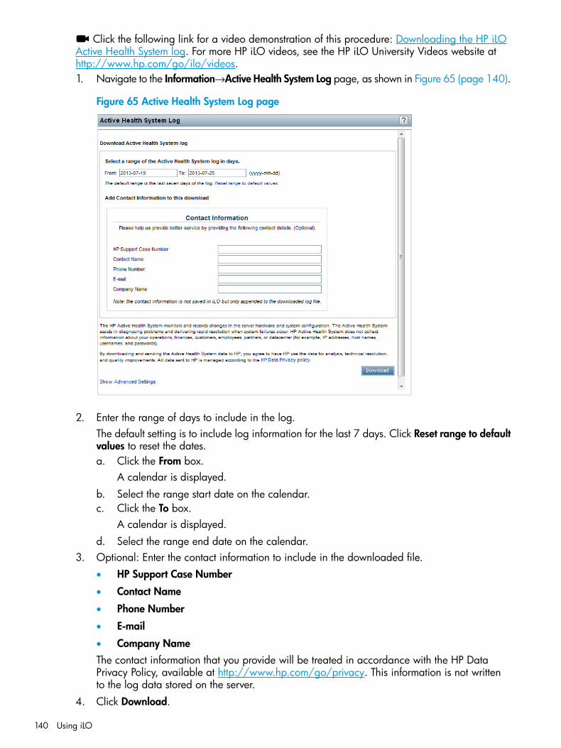
Click the following link for a video demonstration of this procedure: Downloading the HP iLOActive Health System log. For more HP iLO videos, see the HP iLO University Videos website athttp://www.hp.com/go/ilo/videos.1. Navigate to the Information→Active Health System Log page, as shown in Figure 65 (page 140).
Figure 65 Active Health System Log page
2. Enter the range of days to include in the log.The default setting is to include log information for the last 7 days. Click Reset range to defaultvalues to reset the dates.a. Click the From box.
A calendar is displayed.b. Select the range start date on the calendar.c. Click the To box.
A calendar is displayed.d. Select the range end date on the calendar.
3. Optional: Enter the contact information to include in the downloaded file.• HP Support Case Number
• Contact Name
• Phone Number
• Company NameThe contact information that you provide will be treated in accordance with the HP DataPrivacy Policy, available at http://www.hp.com/go/privacy. This information is not writtento the log data stored on the server.
4. Click Download.
140 Using iLO

5. Save the file.The default file name is HP_<server_serial_number>_date.ahs.
6. If you have an open case with HP Support, you can email the log file [email protected] the following convention for the email subject: CASE: <HP support case number>.
NOTE: Files that are larger than 15 MB must be compressed and uploaded to an FTP site.If needed, contact HP Support for FTP site information.
Downloading the entire Active Health System logUse the following procedure to download the entire Active Health System log.It might take a long time to download the entire Active Health System log. If you must upload theActive Health System log for a technical issue, HP recommends downloading the log for the specificrange of dates in which the problem occurred. For instructions, see “Downloading the Active HealthSystem log for a date range” (page 139).
Click the following link for a video demonstration of this procedure: Downloading the HP iLOActive Health System log. For more HP iLO videos, see the HP iLO University Videos website athttp://www.hp.com/go/ilo/videos.1. Navigate to the Information→Active Health System Log page, as shown in Figure 65 (page 140).2. Click Show Advanced Settings.3. Optional: Enter the contact information to include in the downloaded file.
• HP Support Case Number
• Contact Name
• Phone Number
• Company NameThe contact information that you provide will be treated in accordance with the HP DataPrivacy Policy, available at http://www.hp.com/go/privacy. This information is not writtento the log data stored on the server.
4. Click Download Entire Log.5. Save the file.6. If you have an open case with HP Support, you can email the log file to
[email protected] the following convention for the email subject: CASE: <HP support case number>.
NOTE: Files that are larger than 15 MB must be compressed and uploaded to an FTP site.If needed, contact HP Support for FTP site information.
Extracting the Active Health System log by using curliLO 4 1.30 and later supports extracting the Active Health System log with the curl commandline tool.You can download curl from the following website: http://curl.haxx.se/.To download the Active Health System log by using curl:1. Install curl.2. Open a command window.3. Enter the following command to download the Active Health System log for a range of dates:
Using the HP Active Health System 141
curl "https://<iLO IP address>/ahsdata/ahs.ahs?from=<yyyy-mm-dd>&to=<yyyy-mm-dd>" -k -v -u <username>:<password> -o <filename>.ahs
Where:
• <iLO IP address> is the iLO IP address.
• from=<yyyy-mm-dd>&to=<yyyy-mm-dd> represents the start and end date of therange of dates to include in the log. Enter dates in the format year-month-day, forexample, 2013-07-29 for July 29, 2013.
• –k specifies that HTTPS warnings will be ignored.
• –v specifies verbose output.
• -u <username>:<password> specifies your iLO user account credentials.
• –o <filename> specifies the output file name and path.
NOTE: To download the entire log, omit the from and to parameters and use the followingcommand: curl "https://<iLO IP address>/ahsdata/ahs.ahs" -k -v -u<username>:<password> -o <filename>.ahs
The file is saved to the path you specified.4. Close the command window.
Clearing the Active Health System logIf the log file is corrupted, or if you want to clear and restart logging, use the following procedureto clear the Active Health System log. You must have the Configure iLO Settings privilege to performthis procedure.1. Navigate to the Information→Active Health System log page, as shown in Figure 65 (page 140).2. Click Show Advanced Settings.3. Click the Clear button.
The following message appears:Are you sure that you want to clear the entire Active Health Systemlog?
4. Click OK.The following message appears at the top of the page:The AHS Log is being cleared and it may take several minutes. Pleasepress the Refresh button to reload this page.
5. Reset iLO.For instructions, see “Using iLO diagnostics” (page 142).You must reset iLO after clearing the Active Health System log. Some Active Health Systemdata is recorded to the log only during iLO startup. Resetting iLO ensures that a complete setof data is available in the log.
Using iLO diagnosticsThe Diagnostics page displays iLO self-test results and allows you to reset iLO, generate an NMIto the system, or configure redundant ROM.To view iLO diagnostics information, navigate to the Information→Diagnostics page, as shown inFigure 66 (page 143).
142 Using iLO
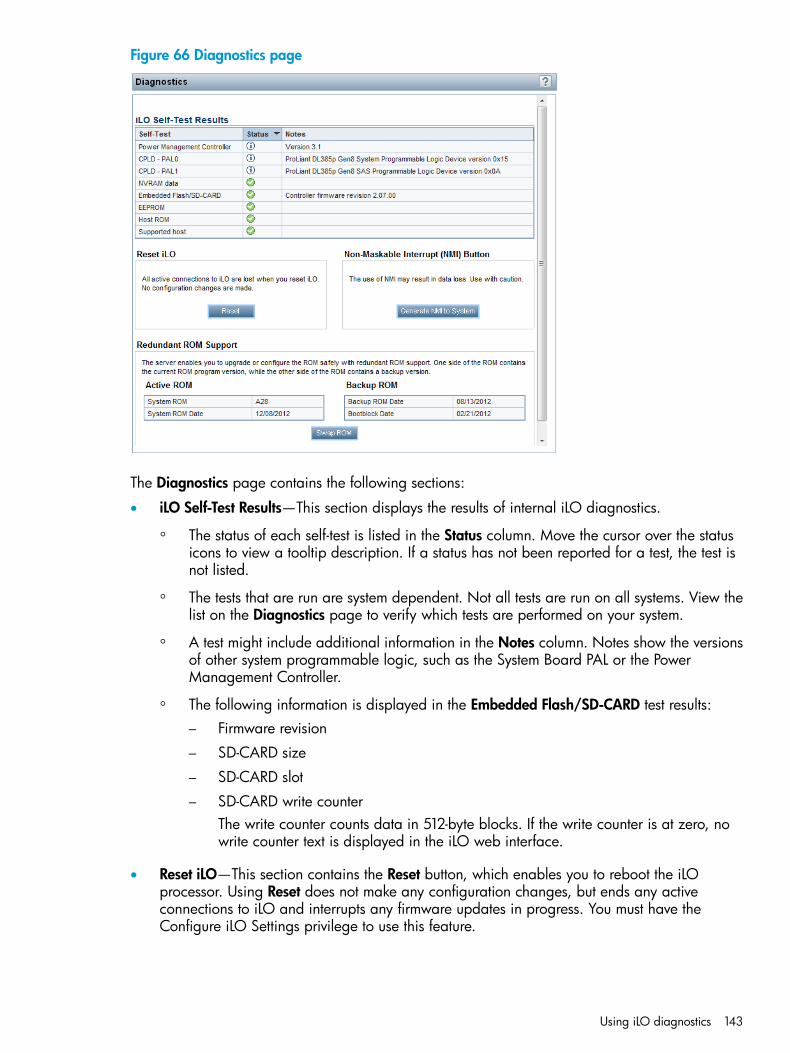
Figure 66 Diagnostics page
The Diagnostics page contains the following sections:
• iLO Self-Test Results—This section displays the results of internal iLO diagnostics.
The status of each self-test is listed in the Status column. Move the cursor over the statusicons to view a tooltip description. If a status has not been reported for a test, the test isnot listed.
◦
◦ The tests that are run are system dependent. Not all tests are run on all systems. View thelist on the Diagnostics page to verify which tests are performed on your system.
◦ A test might include additional information in the Notes column. Notes show the versionsof other system programmable logic, such as the System Board PAL or the PowerManagement Controller.
◦ The following information is displayed in the Embedded Flash/SD-CARD test results:– Firmware revision
– SD-CARD size
– SD-CARD slot
– SD-CARD write counterThe write counter counts data in 512-byte blocks. If the write counter is at zero, nowrite counter text is displayed in the iLO web interface.
• Reset iLO—This section contains the Reset button, which enables you to reboot the iLOprocessor. Using Reset does not make any configuration changes, but ends any activeconnections to iLO and interrupts any firmware updates in progress. You must have theConfigure iLO Settings privilege to use this feature.
Using iLO diagnostics 143
• Non-Maskable Interrupt (NMI) button—This section contains the Generate NMI to Systembutton, which enables you to stop the operating system for debugging. The Virtual Power andReset privilege is required to generate an NMI.
CAUTION: Generating an NMI as a diagnostic and debugging tool is used primarily whenthe operating system is no longer available. NMI is not used during normal operation of theserver. Generating an NMI does not gracefully shut down the operating system, but causesthe operating system to crash, resulting in lost service and data. Use the Generate NMI toSystem button only in extreme cases in which the operating system is not functioning properlyand an experienced support organization has recommended that you proceed with an NMI.
Note the following:
◦ Use the Debug feature if a software application hangs the system. Use the Generate NMIto System button to engage the operating system debugger.
◦ Initiate the dump of an unresponsive host if you want to capture the server context.
• Redundant ROM Support—You can safely upgrade or configure the server ROM with redundantROM support.
◦ The Active ROM table shows the current version and the release date of the system ROMon the local machine.
◦ The Backup ROM table shows the release date of the backup ROM and the release dateof the backup ROM bootblock. The backup ROM is typically the previously installedversion.
Click the Swap ROM button to swap the active ROM and backup ROM. The change will takeeffect after the next system reboot.
Resetting iLO through the web interfaceIf iLO is slow to respond, you might need to perform a reset.1. Navigate to the Information→Diagnostics page in the iLO web interface.2. Click Reset.
Clicking Reset iLO does not make any configuration changes, but it ends any active connectionsto iLO and completes any firmware updates in progress. You must have the Configure iLOSettings privilege to reset iLO using this method.
Click the following link for a video demonstration of this procedure: Resetting iLO. For moreHP iLO videos, see the HP iLO University Videos website at http://www.hp.com/go/ilo/videos.For other reset methods, see “Resetting iLO” (page 262).
Using Location Discovery ServicesLocation Discovery Services is a component of HP Discovery Services. Location Discovery Servicesautomatically reports server locations to HP SIM and Insight Control, eliminating this manual taskfor server administrators. Administrators can use the location information and system data with HPAsset Manager to obtain more precise and complete asset data.Location Discovery Services is a rack U location discovery solution for G3 and later racks. It enablesHP iLO, BL Onboard Administrator, and SL Chassis firmware to report and display the rack ID andthe server U position in the rack. Supported racks are programmed with unique U values in 7Uand/or 8U modules, and are installed with the tag version number, rack identifier, part number,product name, rack height, and U position. Location Discovery Services supports 14U, 22U, 36U,42U, and 47U racks.
144 Using iLO
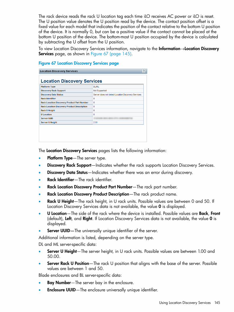
The rack device reads the rack U location tag each time iLO receives AC power or iLO is reset.The U position value denotes the U position read by the device. The contact position offset is afixed value for each model that indicates the position of the contact relative to the bottom U positionof the device. It is normally 0, but can be a positive value if the contact cannot be placed at thebottom U position of the device. The bottom-most U position occupied by the device is calculatedby subtracting the U offset from the U position.To view Location Discovery Services information, navigate to the Information→Location DiscoveryServices page, as shown in Figure 67 (page 145).
Figure 67 Location Discovery Services page
The Location Discovery Services pages lists the following information:
• Platform Type—The server type.
• Discovery Rack Support—Indicates whether the rack supports Location Discovery Services.
• Discovery Data Status—Indicates whether there was an error during discovery.
• Rack Identifier—The rack identifier.
• Rack Location Discovery Product Part Number—The rack part number.
• Rack Location Discovery Product Description—The rack product name.
• Rack U Height—The rack height, in U rack units. Possible values are between 0 and 50. IfLocation Discovery Services data is not available, the value 0 is displayed.
• U Location—The side of the rack where the device is installed. Possible values are Back, Front(default), Left, and Right. If Location Discovery Services data is not available, the value 0 isdisplayed.
• Server UUID—The universally unique identifier of the server.Additional information is listed, depending on the server type.DL and ML server-specific data:• Server U Height—The server height, in U rack units. Possible values are between 1.00 and
50.00.• Server Rack U Position—The rack U position that aligns with the base of the server. Possible
values are between 1 and 50.Blade enclosures and BL server-specific data:
• Bay Number—The server bay in the enclosure.
• Enclosure UUID—The enclosure universally unique identifier.
Using Location Discovery Services 145
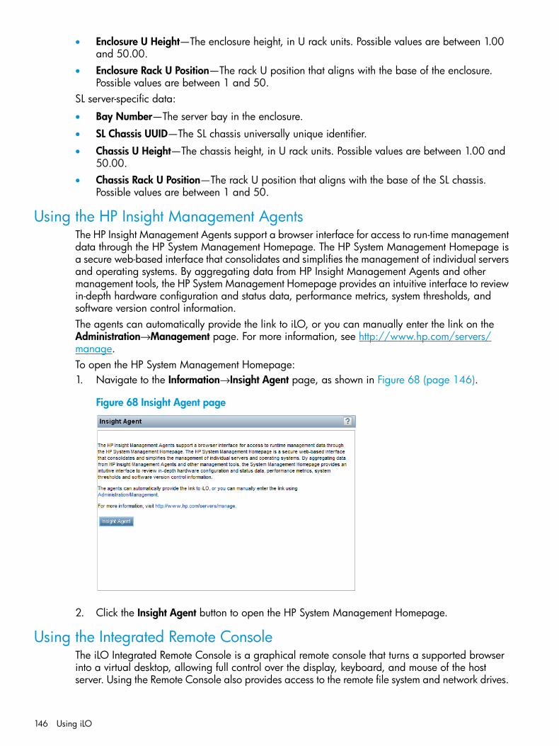
• Enclosure U Height—The enclosure height, in U rack units. Possible values are between 1.00and 50.00.
• Enclosure Rack U Position—The rack U position that aligns with the base of the enclosure.Possible values are between 1 and 50.
SL server-specific data:
• Bay Number—The server bay in the enclosure.
• SL Chassis UUID—The SL chassis universally unique identifier.
• Chassis U Height—The chassis height, in U rack units. Possible values are between 1.00 and50.00.
• Chassis Rack U Position—The rack U position that aligns with the base of the SL chassis.Possible values are between 1 and 50.
Using the HP Insight Management AgentsThe HP Insight Management Agents support a browser interface for access to run-time managementdata through the HP System Management Homepage. The HP System Management Homepage isa secure web-based interface that consolidates and simplifies the management of individual serversand operating systems. By aggregating data from HP Insight Management Agents and othermanagement tools, the HP System Management Homepage provides an intuitive interface to reviewin-depth hardware configuration and status data, performance metrics, system thresholds, andsoftware version control information.The agents can automatically provide the link to iLO, or you can manually enter the link on theAdministration→Management page. For more information, see http://www.hp.com/servers/manage.To open the HP System Management Homepage:1. Navigate to the Information→Insight Agent page, as shown in Figure 68 (page 146).
Figure 68 Insight Agent page
2. Click the Insight Agent button to open the HP System Management Homepage.
Using the Integrated Remote ConsoleThe iLO Integrated Remote Console is a graphical remote console that turns a supported browserinto a virtual desktop, allowing full control over the display, keyboard, and mouse of the hostserver. Using the Remote Console also provides access to the remote file system and network drives.
146 Using iLO
With Integrated Remote Console access, you can observe POST boot messages as the remote hostserver restarts, and initiate ROM-based setup routines to configure the remote host server hardware.When you are installing operating systems remotely, the Integrated Remote Console (if licensed)enables you to view and control the host server monitor throughout the installation process.iLO provides the following Integrated Remote Console access options:
• .NET IRC—Provides access to the system KVM, allowing control of Virtual Power and VirtualMedia from a single console through a supported browser on a Windows client. In additionto the standard features, the .NET IRC supports Console Capture, Shared Console, VirtualFolder, and Scripted Media.
• Java IRC—Provides access to the system KVM, allowing control of Virtual Power and VirtualMedia from a Java-based console. In addition to the standard features, the Java IRC includesthe iLO disk image tool.
• Standalone IRC (HPLOCONS)—Provides full iLO Integrated Remote Console functionality directlyfrom your Windows desktop, without going through the iLO web interface. HPLOCONS hasthe same functionality and requirements as the .NET IRC application that is launched from theiLO web interface. Download HPLOCONS from the HP website: http://www.hp.com/go/ilo.
Click the following link for a video demonstration of this feature: Using the StandaloneRemote Console. For more HP iLO videos, see the HP iLO University Videos website at http://www.hp.com/go/ilo/videos.
• iLO Mobile Application for iOS and Android devices—Provides Integrated Remote Consoleaccess from your supported mobile phone or tablet. For more information, see http://www.hp.com/go/ilo/mobileapp.
For a list of supported browsers, see the “Browser support” (page 109).
.NET IRC requirementsThis section lists the requirements for using the .NET IRC.
Microsoft .NET FrameworkThe .NET IRC requires one of the following versions of the Microsoft .NET Framework. You canuse Windows Update to install the .NET Framework.
• .NET Framework 3.5 Full (SP1 recommended)
• .NET Framework 4.0 Full
• .NET Framework 4.5The .NET Framework versions 3.5 and 4.0 have two deployment options: Full and Client Profile.The Client Profile is a subset of the Full framework. The .NET IRC is supported with the Full frameworkonly; the Client Profile is not supported. Version 4.5 of the .NET Framework does not have theClient Profile option.For Internet Explorer users only: The .NET Framework Detection table on the iLO Integrated RemoteConsole page lists the compatible .NET versions and indicates whether the installed version iscompatible with the .NET IRC. If the installed version is compatible, the status OK is listed in theStatus column.
Microsoft ClickOnceThe .NET IRC is launched using Microsoft ClickOnce, which is part of the .NET Framework.ClickOnce requires that any application installed from an SSL connection be from a trusted source.If a browser is not configured to trust an iLO system, and the IRC requires a trusted certificate iniLO setting is set to Enabled, ClickOnce displays the following error message:Cannot Start Application - Application download did not succeed....
Using the Integrated Remote Console 147
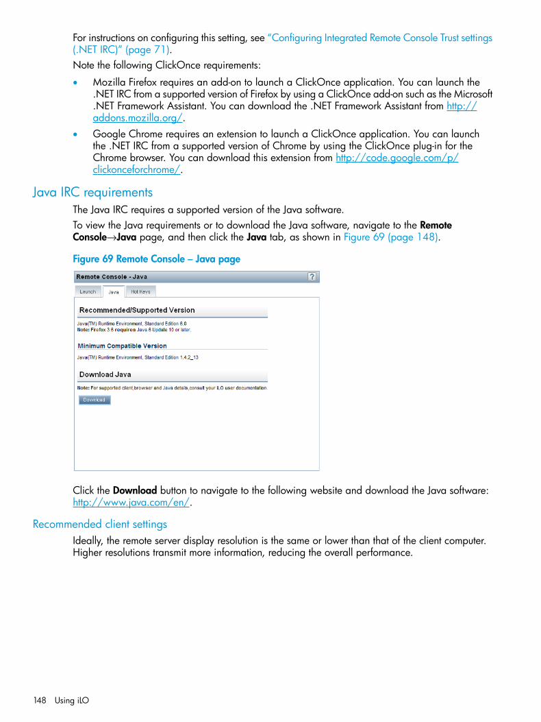
For instructions on configuring this setting, see “Configuring Integrated Remote Console Trust settings(.NET IRC)” (page 71).Note the following ClickOnce requirements:
• Mozilla Firefox requires an add-on to launch a ClickOnce application. You can launch the.NET IRC from a supported version of Firefox by using a ClickOnce add-on such as the Microsoft.NET Framework Assistant. You can download the .NET Framework Assistant from http://addons.mozilla.org/.
• Google Chrome requires an extension to launch a ClickOnce application. You can launchthe .NET IRC from a supported version of Chrome by using the ClickOnce plug-in for theChrome browser. You can download this extension from http://code.google.com/p/clickonceforchrome/.
Java IRC requirementsThe Java IRC requires a supported version of the Java software.To view the Java requirements or to download the Java software, navigate to the RemoteConsole→Java page, and then click the Java tab, as shown in Figure 69 (page 148).
Figure 69 Remote Console – Java page
Click the Download button to navigate to the following website and download the Java software:http://www.java.com/en/.
Recommended client settingsIdeally, the remote server display resolution is the same or lower than that of the client computer.Higher resolutions transmit more information, reducing the overall performance.
148 Using iLO
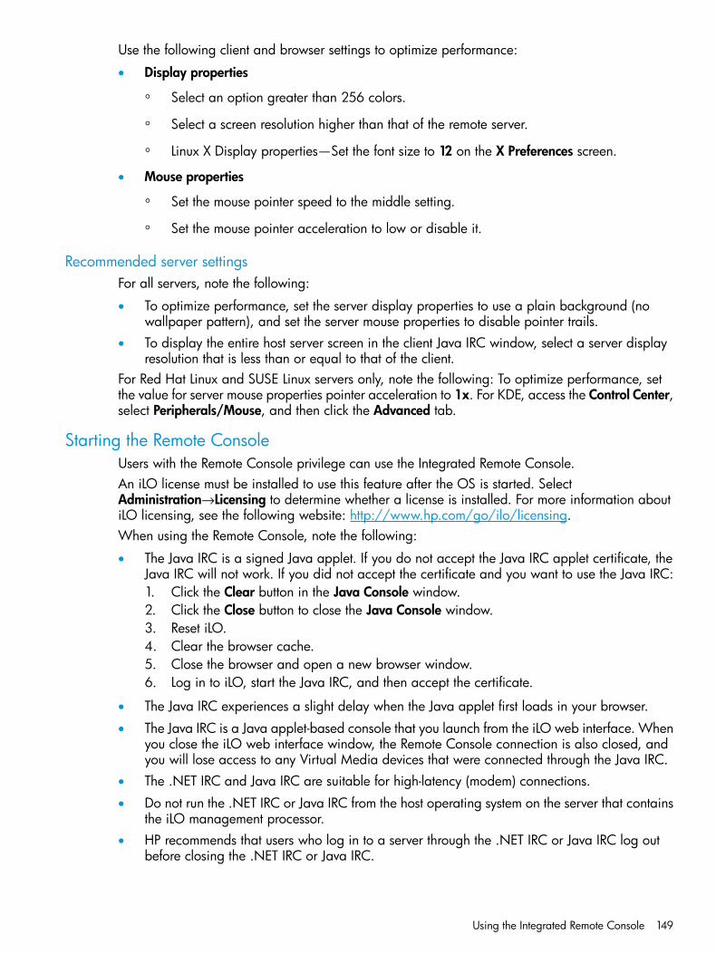
Use the following client and browser settings to optimize performance:
• Display properties
Select an option greater than 256 colors.◦◦ Select a screen resolution higher than that of the remote server.
◦ Linux X Display properties—Set the font size to 12 on the X Preferences screen.
• Mouse properties
Set the mouse pointer speed to the middle setting.◦◦ Set the mouse pointer acceleration to low or disable it.
Recommended server settingsFor all servers, note the following:
• To optimize performance, set the server display properties to use a plain background (nowallpaper pattern), and set the server mouse properties to disable pointer trails.
• To display the entire host server screen in the client Java IRC window, select a server displayresolution that is less than or equal to that of the client.
For Red Hat Linux and SUSE Linux servers only, note the following: To optimize performance, setthe value for server mouse properties pointer acceleration to 1x. For KDE, access the Control Center,select Peripherals/Mouse, and then click the Advanced tab.
Starting the Remote ConsoleUsers with the Remote Console privilege can use the Integrated Remote Console.An iLO license must be installed to use this feature after the OS is started. SelectAdministration→Licensing to determine whether a license is installed. For more information aboutiLO licensing, see the following website: http://www.hp.com/go/ilo/licensing.When using the Remote Console, note the following:
• The Java IRC is a signed Java applet. If you do not accept the Java IRC applet certificate, theJava IRC will not work. If you did not accept the certificate and you want to use the Java IRC:1. Click the Clear button in the Java Console window.2. Click the Close button to close the Java Console window.3. Reset iLO.4. Clear the browser cache.5. Close the browser and open a new browser window.6. Log in to iLO, start the Java IRC, and then accept the certificate.
• The Java IRC experiences a slight delay when the Java applet first loads in your browser.
• The Java IRC is a Java applet-based console that you launch from the iLO web interface. Whenyou close the iLO web interface window, the Remote Console connection is also closed, andyou will lose access to any Virtual Media devices that were connected through the Java IRC.
• The .NET IRC and Java IRC are suitable for high-latency (modem) connections.
• Do not run the .NET IRC or Java IRC from the host operating system on the server that containsthe iLO management processor.
• HP recommends that users who log in to a server through the .NET IRC or Java IRC log outbefore closing the .NET IRC or Java IRC.
Using the Integrated Remote Console 149
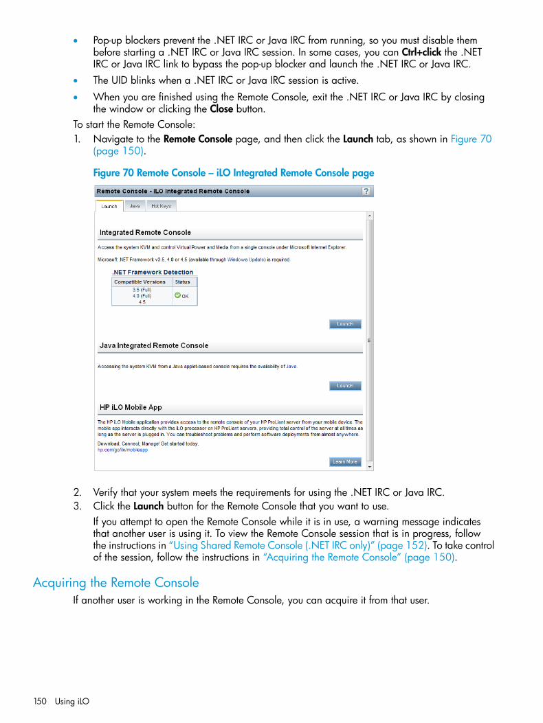
• Pop-up blockers prevent the .NET IRC or Java IRC from running, so you must disable thembefore starting a .NET IRC or Java IRC session. In some cases, you can Ctrl+click the .NETIRC or Java IRC link to bypass the pop-up blocker and launch the .NET IRC or Java IRC.
• The UID blinks when a .NET IRC or Java IRC session is active.
• When you are finished using the Remote Console, exit the .NET IRC or Java IRC by closingthe window or clicking the Close button.
To start the Remote Console:1. Navigate to the Remote Console page, and then click the Launch tab, as shown in Figure 70
(page 150).
Figure 70 Remote Console – iLO Integrated Remote Console page
2. Verify that your system meets the requirements for using the .NET IRC or Java IRC.3. Click the Launch button for the Remote Console that you want to use.
If you attempt to open the Remote Console while it is in use, a warning message indicatesthat another user is using it. To view the Remote Console session that is in progress, followthe instructions in “Using Shared Remote Console (.NET IRC only)” (page 152). To take controlof the session, follow the instructions in “Acquiring the Remote Console” (page 150).
Acquiring the Remote ConsoleIf another user is working in the Remote Console, you can acquire it from that user.
150 Using iLO
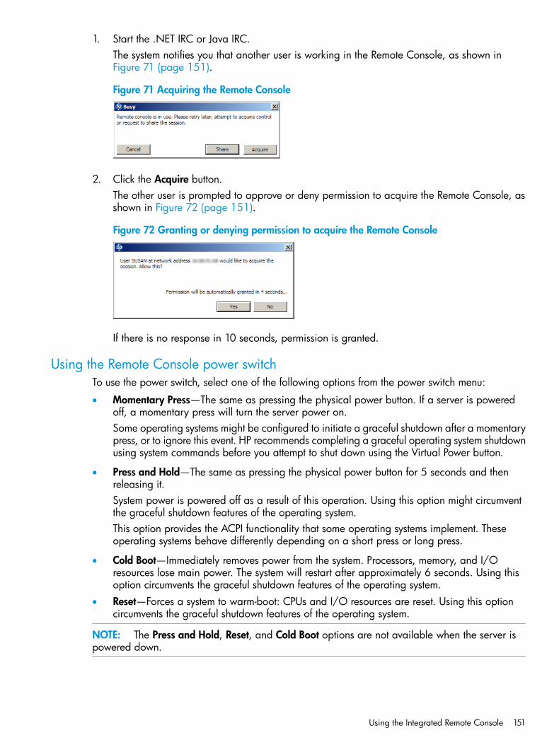
1. Start the .NET IRC or Java IRC.The system notifies you that another user is working in the Remote Console, as shown inFigure 71 (page 151).
Figure 71 Acquiring the Remote Console
2. Click the Acquire button.The other user is prompted to approve or deny permission to acquire the Remote Console, asshown in Figure 72 (page 151).
Figure 72 Granting or denying permission to acquire the Remote Console
If there is no response in 10 seconds, permission is granted.
Using the Remote Console power switchTo use the power switch, select one of the following options from the power switch menu:
• Momentary Press—The same as pressing the physical power button. If a server is poweredoff, a momentary press will turn the server power on.Some operating systems might be configured to initiate a graceful shutdown after a momentarypress, or to ignore this event. HP recommends completing a graceful operating system shutdownusing system commands before you attempt to shut down using the Virtual Power button.
• Press and Hold—The same as pressing the physical power button for 5 seconds and thenreleasing it.System power is powered off as a result of this operation. Using this option might circumventthe graceful shutdown features of the operating system.This option provides the ACPI functionality that some operating systems implement. Theseoperating systems behave differently depending on a short press or long press.
• Cold Boot—Immediately removes power from the system. Processors, memory, and I/Oresources lose main power. The system will restart after approximately 6 seconds. Using thisoption circumvents the graceful shutdown features of the operating system.
• Reset—Forces a system to warm-boot: CPUs and I/O resources are reset. Using this optioncircumvents the graceful shutdown features of the operating system.
NOTE: The Press and Hold, Reset, and Cold Boot options are not available when the server ispowered down.
Using the Integrated Remote Console 151
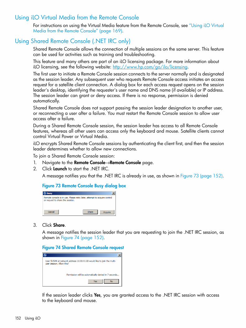
Using iLO Virtual Media from the Remote ConsoleFor instructions on using the Virtual Media feature from the Remote Console, see “Using iLO VirtualMedia from the Remote Console” (page 169).
Using Shared Remote Console (.NET IRC only)Shared Remote Console allows the connection of multiple sessions on the same server. This featurecan be used for activities such as training and troubleshooting.This feature and many others are part of an iLO licensing package. For more information aboutiLO licensing, see the following website: http://www.hp.com/go/ilo/licensing.The first user to initiate a Remote Console session connects to the server normally and is designatedas the session leader. Any subsequent user who requests Remote Console access initiates an accessrequest for a satellite client connection. A dialog box for each access request opens on the sessionleader's desktop, identifying the requester's user name and DNS name (if available) or IP address.The session leader can grant or deny access. If there is no response, permission is deniedautomatically.Shared Remote Console does not support passing the session leader designation to another user,or reconnecting a user after a failure. You must restart the Remote Console session to allow useraccess after a failure.During a Shared Remote Console session, the session leader has access to all Remote Consolefeatures, whereas all other users can access only the keyboard and mouse. Satellite clients cannotcontrol Virtual Power or Virtual Media.iLO encrypts Shared Remote Console sessions by authenticating the client first, and then the sessionleader determines whether to allow new connections.To join a Shared Remote Console session:1. Navigate to the Remote Console→Remote Console page.2. Click Launch to start the .NET IRC.
A message notifies you that the .NET IRC is already in use, as shown in Figure 73 (page 152).
Figure 73 Remote Console Busy dialog box
3. Click Share.A message notifies the session leader that you are requesting to join the .NET IRC session, asshown in Figure 74 (page 152).
Figure 74 Shared Remote Console request
If the session leader clicks Yes, you are granted access to the .NET IRC session with accessto the keyboard and mouse.
152 Using iLO
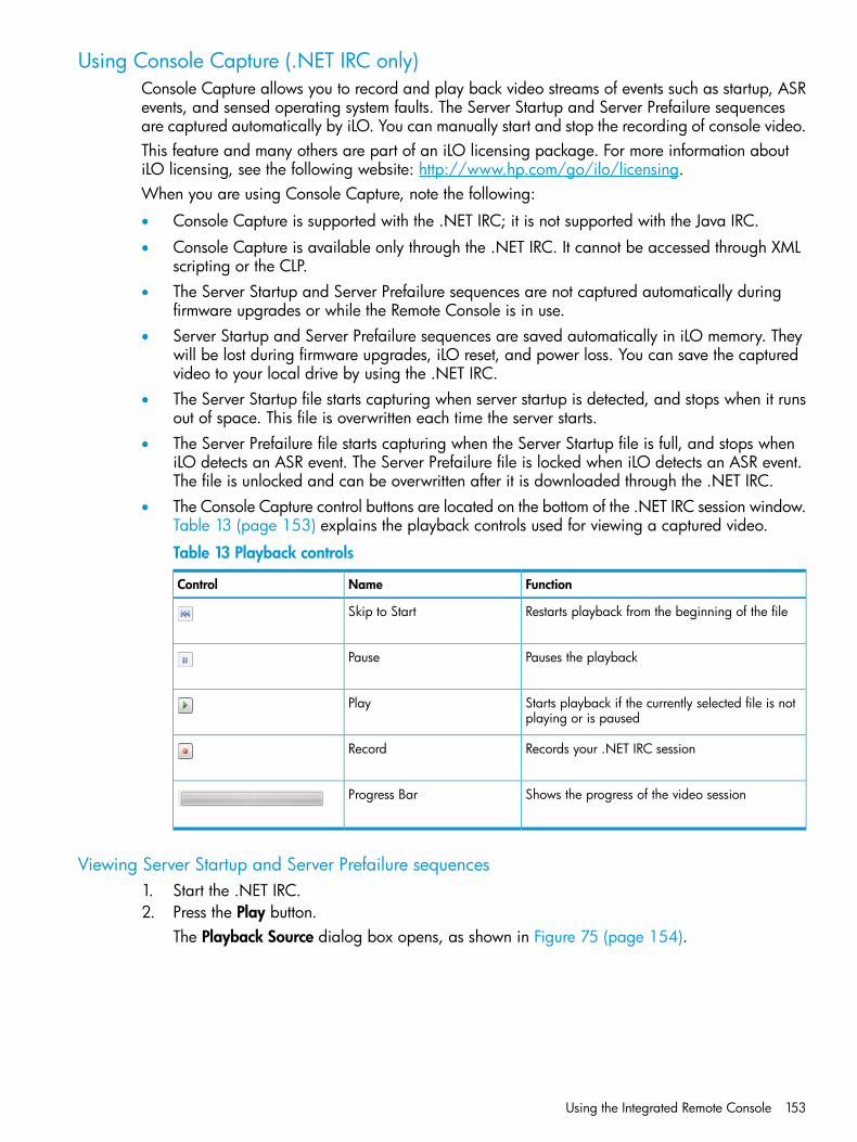
Using Console Capture (.NET IRC only)Console Capture allows you to record and play back video streams of events such as startup, ASRevents, and sensed operating system faults. The Server Startup and Server Prefailure sequencesare captured automatically by iLO. You can manually start and stop the recording of console video.This feature and many others are part of an iLO licensing package. For more information aboutiLO licensing, see the following website: http://www.hp.com/go/ilo/licensing.When you are using Console Capture, note the following:
• Console Capture is supported with the .NET IRC; it is not supported with the Java IRC.
• Console Capture is available only through the .NET IRC. It cannot be accessed through XMLscripting or the CLP.
• The Server Startup and Server Prefailure sequences are not captured automatically duringfirmware upgrades or while the Remote Console is in use.
• Server Startup and Server Prefailure sequences are saved automatically in iLO memory. Theywill be lost during firmware upgrades, iLO reset, and power loss. You can save the capturedvideo to your local drive by using the .NET IRC.
• The Server Startup file starts capturing when server startup is detected, and stops when it runsout of space. This file is overwritten each time the server starts.
• The Server Prefailure file starts capturing when the Server Startup file is full, and stops wheniLO detects an ASR event. The Server Prefailure file is locked when iLO detects an ASR event.The file is unlocked and can be overwritten after it is downloaded through the .NET IRC.
• The Console Capture control buttons are located on the bottom of the .NET IRC session window.Table 13 (page 153) explains the playback controls used for viewing a captured video.
Table 13 Playback controls
FunctionNameControl
Restarts playback from the beginning of the fileSkip to Start
Pauses the playbackPause
Starts playback if the currently selected file is notplaying or is paused
Play
Records your .NET IRC sessionRecord
Shows the progress of the video sessionProgress Bar
Viewing Server Startup and Server Prefailure sequences1. Start the .NET IRC.2. Press the Play button.
The Playback Source dialog box opens, as shown in Figure 75 (page 154).
Using the Integrated Remote Console 153
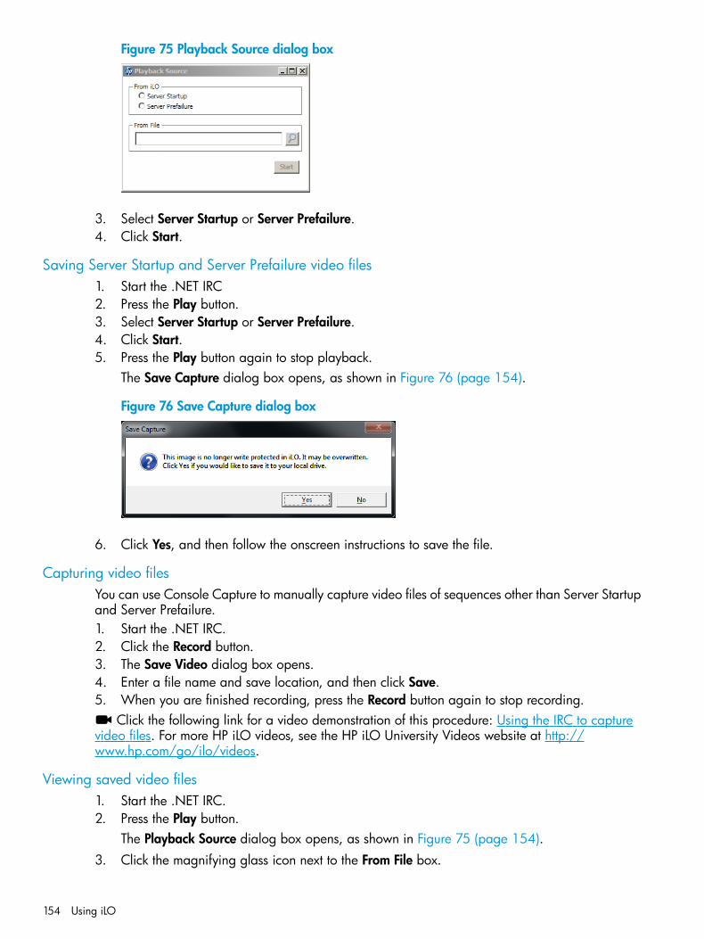
Figure 75 Playback Source dialog box
3. Select Server Startup or Server Prefailure.4. Click Start.
Saving Server Startup and Server Prefailure video files1. Start the .NET IRC2. Press the Play button.3. Select Server Startup or Server Prefailure.4. Click Start.5. Press the Play button again to stop playback.
The Save Capture dialog box opens, as shown in Figure 76 (page 154).
Figure 76 Save Capture dialog box
6. Click Yes, and then follow the onscreen instructions to save the file.
Capturing video filesYou can use Console Capture to manually capture video files of sequences other than Server Startupand Server Prefailure.1. Start the .NET IRC.2. Click the Record button.3. The Save Video dialog box opens.4. Enter a file name and save location, and then click Save.5. When you are finished recording, press the Record button again to stop recording.
Click the following link for a video demonstration of this procedure: Using the IRC to capturevideo files. For more HP iLO videos, see the HP iLO University Videos website at http://www.hp.com/go/ilo/videos.
Viewing saved video files1. Start the .NET IRC.2. Press the Play button.
The Playback Source dialog box opens, as shown in Figure 75 (page 154).3. Click the magnifying glass icon next to the From File box.
154 Using iLO
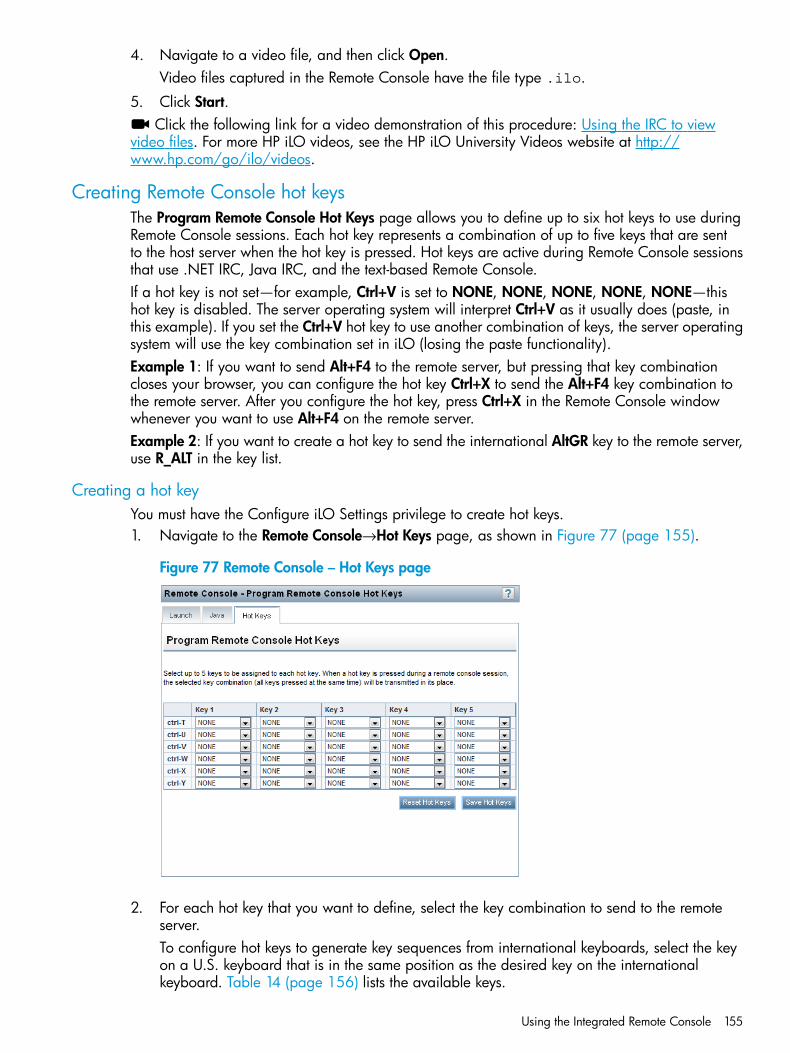
4. Navigate to a video file, and then click Open.Video files captured in the Remote Console have the file type .ilo.
5. Click Start.Click the following link for a video demonstration of this procedure: Using the IRC to view
video files. For more HP iLO videos, see the HP iLO University Videos website at http://www.hp.com/go/ilo/videos.
Creating Remote Console hot keysThe Program Remote Console Hot Keys page allows you to define up to six hot keys to use duringRemote Console sessions. Each hot key represents a combination of up to five keys that are sentto the host server when the hot key is pressed. Hot keys are active during Remote Console sessionsthat use .NET IRC, Java IRC, and the text-based Remote Console.If a hot key is not set—for example, Ctrl+V is set to NONE, NONE, NONE, NONE, NONE—thishot key is disabled. The server operating system will interpret Ctrl+V as it usually does (paste, inthis example). If you set the Ctrl+V hot key to use another combination of keys, the server operatingsystem will use the key combination set in iLO (losing the paste functionality).Example 1: If you want to send Alt+F4 to the remote server, but pressing that key combinationcloses your browser, you can configure the hot key Ctrl+X to send the Alt+F4 key combination tothe remote server. After you configure the hot key, press Ctrl+X in the Remote Console windowwhenever you want to use Alt+F4 on the remote server.Example 2: If you want to create a hot key to send the international AltGR key to the remote server,use R_ALT in the key list.
Creating a hot keyYou must have the Configure iLO Settings privilege to create hot keys.1. Navigate to the Remote Console→Hot Keys page, as shown in Figure 77 (page 155).
Figure 77 Remote Console – Hot Keys page
2. For each hot key that you want to define, select the key combination to send to the remoteserver.To configure hot keys to generate key sequences from international keyboards, select the keyon a U.S. keyboard that is in the same position as the desired key on the internationalkeyboard. Table 14 (page 156) lists the available keys.
Using the Integrated Remote Console 155
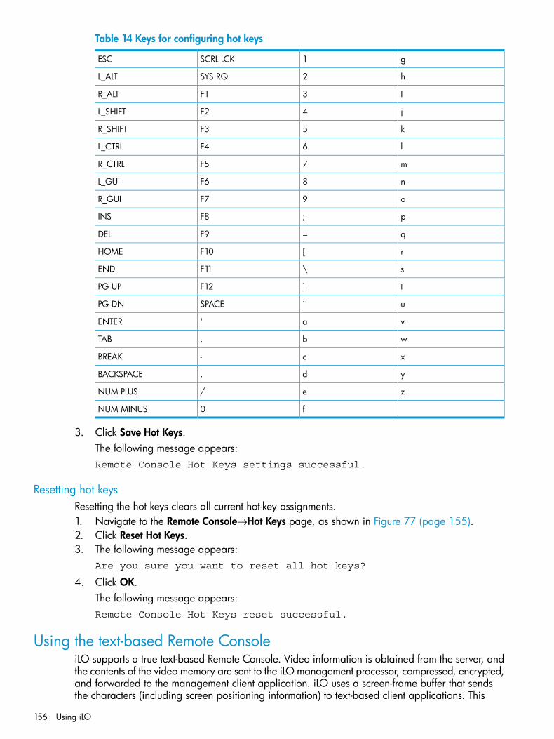
Table 14 Keys for configuring hot keys
g1SCRL LCKESC
h2SYS RQL_ALT
I3F1R_ALT
j4F2L_SHIFT
k5F3R_SHIFT
l6F4L_CTRL
m7F5R_CTRL
n8F6L_GUI
o9F7R_GUI
p;F8INS
q=F9DEL
r[F10HOME
s\F11END
t]F12PG UP
u`SPACEPG DN
va'ENTER
wb,TAB
xc-BREAK
yd.BACKSPACE
ze/NUM PLUS
f0NUM MINUS
3. Click Save Hot Keys.The following message appears:Remote Console Hot Keys settings successful.
Resetting hot keysResetting the hot keys clears all current hot-key assignments.1. Navigate to the Remote Console→Hot Keys page, as shown in Figure 77 (page 155).2. Click Reset Hot Keys.3. The following message appears:
Are you sure you want to reset all hot keys?
4. Click OK.The following message appears:Remote Console Hot Keys reset successful.
Using the text-based Remote ConsoleiLO supports a true text-based Remote Console. Video information is obtained from the server, andthe contents of the video memory are sent to the iLO management processor, compressed, encrypted,and forwarded to the management client application. iLO uses a screen-frame buffer that sendsthe characters (including screen positioning information) to text-based client applications. This
156 Using iLO

method ensures compatibility with standard text-based clients, good performance, and simplicity.However, you cannot display non-ASCII or graphical information, and screen positioning information(displayed characters) might be sent out of order.iLO uses the video adapter DVO port to access video memory directly. This method increases iLOperformance significantly. However, the digital video stream does not contain useful text data.This data cannot be rendered by a text-based client application such as SSH.There are two text-based console options, as described in the following sections:
• “Using the iLO Virtual Serial Port” (page 157)
• “Using the Text-based Remote Console (Textcons)” (page 161)
Using the iLO Virtual Serial PortYou can access a text-based console from iLO using a standard license and the iLO Virtual SerialPort.The iLO Virtual Serial Port is one type of iLO text-based remote console. The iLO Virtual Serial Portgives you a bidirectional data flow with a server serial port. Using the remote console, you canoperate as if a physical serial connection exists on the remote server serial port.The iLO Virtual Serial Port is displayed as a text-based console, but the information is renderedthrough graphical video data. iLO displays this information through an SSH client when the serveris in a pre-operating-system state, enabling a nonlicensed iLO to observe and interact with theserver during POST activities.By using the iLO Virtual Serial Port, the remote user can perform operations such as the following:
• Interact with the server POST sequence and the operating system boot sequence.
• Establish a login session with the operating system, interact with the operating system; andexecute and interact with applications on the operating system.
• For an iLO running Linux in a graphical format, you can configure getty() on the serverserial port, and then use the iLO Virtual Serial Port to view a login session to the Linux operatingsystem. For more information, see “Configuring the iLO Virtual Serial Port for Linux” (page 160).
• Use the EMS Console through the iLO Virtual Serial Port. EMS is useful for debugging Windowsboot issues and kernel-level issues. For more information, see “Configuring the iLO VirtualSerial Port for the Windows EMS Console” (page 161).
Click the following link for a video demonstration of this feature: Using the iLO Virtual SerialPort. For more HP iLO videos, see the HP iLO University Videos website at http://www.hp.com/go/ilo/videos.
Configuring the iLO Virtual Serial Port in the host system RBSUThe following procedure describes the settings you must configure before you can use the iLOVirtual Serial Port. This procedure is required for both Windows and Linux systems.1. Press F9 during the server startup sequence to start the system RBSU.2. Select System Options, and then press Enter.3. Select Serial Port Options, and then press Enter.4. Select Virtual Serial Port, and then press Enter.5. Select the COM port you want to use, and then press Enter, as shown in Figure 78 (page 158).
Using the text-based Remote Console 157
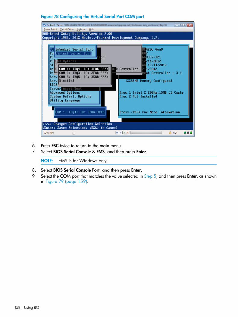
Figure 78 Configuring the Virtual Serial Port COM port
6. Press ESC twice to return to the main menu.7. Select BIOS Serial Console & EMS, and then press Enter.
NOTE: EMS is for Windows only.
8. Select BIOS Serial Console Port, and then press Enter.9. Select the COM port that matches the value selected in Step 5, and then press Enter, as shown
in Figure 79 (page 159).
158 Using iLO
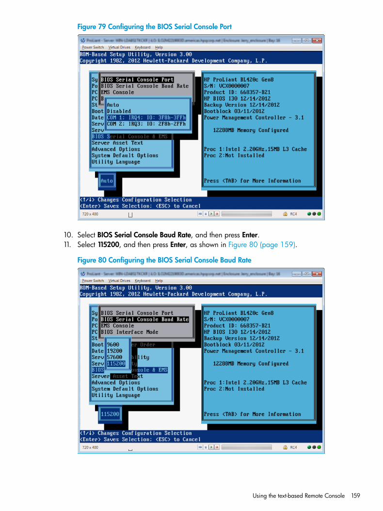
Figure 79 Configuring the BIOS Serial Console Port
10. Select BIOS Serial Console Baud Rate, and then press Enter.11. Select 115200, and then press Enter, as shown in Figure 80 (page 159).
Figure 80 Configuring the BIOS Serial Console Baud Rate
Using the text-based Remote Console 159
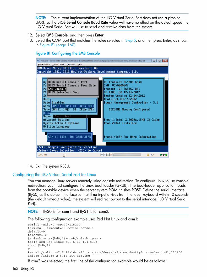
NOTE: The current implementation of the iLO Virtual Serial Port does not use a physicalUART, so the BIOS Serial Console Baud Rate value will have no effect on the actual speed theiLO Virtual Serial Port will use to send and receive data from the system.
12. Select EMS Console, and then press Enter.13. Select the COM port that matches the value selected in Step 5, and then press Enter, as shown
in Figure 81 (page 160).
Figure 81 Configuring the EMS Console
14. Exit the system RBSU.
Configuring the iLO Virtual Serial Port for LinuxYou can manage Linux servers remotely using console redirection. To configure Linux to use consoleredirection, you must configure the Linux boot loader (GRUB). The boot-loader application loadsfrom the bootable device when the server system ROM finishes POST. Define the serial interface(ttyS0) as the default interface so that if no input arrives from the local keyboard within 10 seconds(the default timeout value), the system will redirect output to the serial interface (iLO Virtual SerialPort).
NOTE: ttyS0 is for com1 and ttyS1 is for com2.
The following configuration example uses Red Hat Linux and com1:serial -unit=0 -speed=115200terminal -timeout=10 serial consoledefault=0timeout=10#splashimage=(hd0,2)/grub/splash.xpm.gztitle Red Hat Linux (2. 6.18-164.e15)root (hd0,2)9kernel /vmlinux-2.6.18-164.e15 ro root=/dev/sda9 console=tty0 console=ttyS1,115200initrd /initrd-2.6.18-164.e15.img
If com2 was selected, the first line of the configuration example would be as follows:
160 Using iLO
serial -unit=1 -speed=115200
After Linux is fully booted, a login console can be redirected to the serial port.
• If configured, the /dev/ttyS0 and /dev/ttyS1 devices enable you to obtain serial TTYsessions through the iLO Virtual Serial Port. To begin a shell session on a configured serialport, add the following line to the /etc/inittab file to start the login process automaticallyduring system boot.The following example initiates the login console on /dev/ttyS0:S0:2345:respawn:/sbin/agetty 115200 ttyS0 vt100
The following example initiates the login console on dev/ttys1:
S1:2345:respawn:/sbin/agetty 115200 ttyS1 vt100
• Use SSH to connect to iLO, and then use the iLO CLP command start/system1/oemhp_vsp1 to view a login session to the Linux operating system.
Configuring the iLO Virtual Serial Port for the Windows EMS ConsoleiLO enables you to use the Windows EMS Console over the network through a web browser. EMSenables you to perform emergency management services when video, device drivers, or otheroperating system features prevent normal operation and normal corrective actions from beingperformed.When using the Windows EMS Console with ILO, note the following:
• You must configure the Windows EMS console within the operating system before you canuse the iLO Virtual Serial Port. For information about how to enable the EMS console, seeyour operating system documentation. If the EMS console is not enabled in the operatingsystem, iLO displays an error message when you try to access the iLO Virtual Serial Port.
• The Windows EMS serial port must be enabled through the host system RBSU. The configurationallows you to enable or disable the EMS port, and select the COM port. iLO automaticallydetects whether the EMS port is enabled or disabled, and detects the selection of the COMport. For more information about enabling the Windows EMS serial port, see “Configuringthe iLO Virtual Serial Port in the host system RBSU” (page 157).
• You can use the Windows EMS Console and the iLO Remote Console at the same time.
• To display the SAC> prompt, you might have to press Enter after connecting through the iLOVirtual Serial Port.
Viewing the iLO Virtual Serial Port logIf the iLO Virtual Serial Port log is enabled, you can view iLO Virtual Serial Port activity by usingthe vsp log command.1. Verify that an iLO Advanced or iLO Scale-Out license is installed.2. Enable Secure Shell (SSH) Access and Virtual Serial Port Log on the Access Settings page.
For instructions, see “Configuring iLO access settings” (page 39).3. Connect to the CLI through SSH.4. Use the vsp command to view iLO Virtual Serial Port activity.5. Enter ESC ( to exit.6. Enter vsp log to view the iLO Virtual Serial Port log.
Using the Text-based Remote Console (Textcons)You can access the Text-based Remote Console (Textcons) using a licensed iLO system and SSH.When you use SSH, the data stream, including authentication credentials, is protected by theencryption method that the SSH client and iLO use.
Using the text-based Remote Console 161
NOTE: For more information about iLO licensing, see the following website: http://www.hp.com/go/ilo/licensing.
When you use the Text-based Remote Console, the presentation of colors, characters, and screencontrols depends on the client you are using, which can be any standard SSH client compatiblewith iLO. Features and support include the following:
• Display of text-mode screens that are 80x25 (standard color configurations), including:
System boot process (POST)◦◦ Standard option ROMs
◦ Text boot loaders (LILO or GRUB)
◦ Linux operating system in VGA 80x25 mode
◦ DOS
◦ Other text-based operating systems
• International language keyboards (if the server and client systems have a similar configuration)
• Line-drawing characters when the correct font and code page are selected in the clientapplication
Customizing the Text-based Remote ConsoleYou can use the textcons command options and arguments to customize the Text-based RemoteConsole display. In general, you do not need to change these options.
• To control the sampling rate:Use the textcons speed option to indicate, in ms, the time between each sampling period.A sampling period is when the iLO firmware examines screen changes and updates theText-based Remote Console. Adjusting the speed can alleviate unnecessary traffic on long orslow network links, reduce bandwidth use, and reduce iLO CPU time. HP recommends thatyou specify a value between 1 and 5,000 (1 ms to 5 seconds). For example:textcons speed 500
• To control smoothing:iLO attempts to transmit data only when it changes and becomes stable on the screen. If aline of the text screen is changing faster than iLO can sample the change, the line is nottransmitted until it becomes stable.When a Text-based Remote Console session is active, the data is displayed rapidly and isessentially indecipherable. If the data is transmitted by iLO across the network, it consumesbandwidth. The default behavior is smoothing (delay 0), which transmits data only whenthe changes become stable on the screen. You can control or disable smoothing by using thedelay option. For example:textcons speed 500 delay 10
• To configure character mapping:In the ASCII character set, CONTROL characters (ASCII characters less than 32) are notprintable and are not displayed. These characters can be used to represent items such asarrows, stars, or circles. Some of the characters are mapped to equivalent ASCIIrepresentations. Table 15 (page 163) lists the supported equivalents.
162 Using iLO
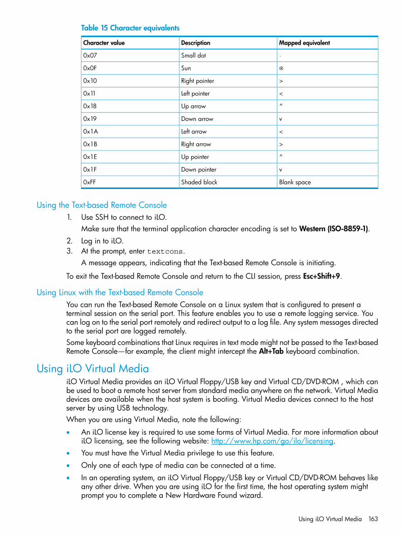
Table 15 Character equivalents
Mapped equivalentDescriptionCharacter value
Small dot0x07
Sun0x0F
>Right pointer0x10
<Left pointer0x11
^Up arrow0x18
vDown arrow0x19
<Left arrow0x1A
>Right arrow0x1B
^Up pointer0x1E
vDown pointer0x1F
Blank spaceShaded block0xFF
Using the Text-based Remote Console1. Use SSH to connect to iLO.
Make sure that the terminal application character encoding is set to Western (ISO-8859-1).2. Log in to iLO.3. At the prompt, enter textcons.
A message appears, indicating that the Text-based Remote Console is initiating.
To exit the Text-based Remote Console and return to the CLI session, press Esc+Shift+9.
Using Linux with the Text-based Remote ConsoleYou can run the Text-based Remote Console on a Linux system that is configured to present aterminal session on the serial port. This feature enables you to use a remote logging service. Youcan log on to the serial port remotely and redirect output to a log file. Any system messages directedto the serial port are logged remotely.Some keyboard combinations that Linux requires in text mode might not be passed to the Text-basedRemote Console—for example, the client might intercept the Alt+Tab keyboard combination.
Using iLO Virtual MediaiLO Virtual Media provides an iLO Virtual Floppy/USB key and Virtual CD/DVD-ROM , which canbe used to boot a remote host server from standard media anywhere on the network. Virtual Mediadevices are available when the host system is booting. Virtual Media devices connect to the hostserver by using USB technology.When you are using Virtual Media, note the following:
• An iLO license key is required to use some forms of Virtual Media. For more information aboutiLO licensing, see the following website: http://www.hp.com/go/ilo/licensing.
• You must have the Virtual Media privilege to use this feature.
• Only one of each type of media can be connected at a time.
• In an operating system, an iLO Virtual Floppy/USB key or Virtual CD/DVD-ROM behaves likeany other drive. When you are using iLO for the first time, the host operating system mightprompt you to complete a New Hardware Found wizard.
Using iLO Virtual Media 163
• When virtual devices are connected, they are available to the host server until you disconnectthem. When you are finished using a Virtual Media device and you disconnect it, you mightreceive a warning message from the host operating system regarding unsafe removal of adevice. You can avoid this warning by using the operating system feature to stop the devicebefore disconnecting it.
• The iLO Virtual Floppy/USB key or Virtual CD/DVD-ROM is available at server boot time forsupported operating systems. Booting from an iLO Virtual Floppy/USB key or VirtualCD/DVD-ROM enables you to perform tasks such as deploying an operating system fromnetwork drives and performing disaster recovery of failed operating systems.
• If the host server operating system supports USB mass storage devices or secure digital devices,the iLO Virtual Floppy/USB key is available after the host server operating system loads.
◦ You can use the iLO Virtual Floppy/USB key when the host server operating system isrunning to upgrade device drivers, create an emergency repair disk, and perform othertasks.
◦ Having the iLO Virtual Floppy/USB key available when the server is running can be usefulif you must diagnose and repair the NIC driver.
◦ The iLO Virtual Floppy/USB key can be the physical floppy disk, USB key, or securedigital drive on which the web browser is running, or an image file stored on your localhard drive or network drive.
◦ For optimal performance, HP recommends using image files stored on the hard drive ofyour client PC or on a network drive accessible through a high-speed network link.
• If the host server operating system supports USB mass storage devices, the iLO VirtualCD/DVD-ROM is available after the host server operating system loads.
◦ You can use the iLO Virtual CD/DVD-ROM when the host server operating system isrunning to upgrade device drivers, install software, and perform other tasks.
◦ Having the iLO Virtual CD/DVD-ROM available when the server is running can be usefulif you must diagnose and repair the NIC driver.
◦ The iLO Virtual CD/DVD-ROM can be the physical CD/DVD-ROM drive on which theweb browser is running, or an image file stored on your local hard drive or networkdrive.
◦ For optimal performance, HP recommends using image files stored on the hard drive ofyour client PC or on a network drive accessible through a high-speed network link.
• You can use the .NET IRC to mount a Virtual Folder to access and copy files between a clientand a managed server.
• Before you use the iLO Virtual Media feature, review the operating system considerations in“Virtual Media operating system information” (page 165).
• You can also access the Virtual Media feature using the .NET IRC or Java IRC, XMLconfiguration and control scripts, or the SMASH CLP.
• If the Virtual Floppy/USB key or Virtual CD/DVD-ROM capability is enabled, you cannottypically access the floppy drive or CD/DVD-ROM drive from the client operating system.
CAUTION: To prevent file and data corruption, do not access the local media when youare using it as iLO Virtual Media.
164 Using iLO
Virtual Media operating system informationThis section describes the operating system requirements to consider when you are using the iLOVirtual Media features.
Operating system USB requirementTo use Virtual Media devices, your operating system must support USB devices, including USBmass storage devices. For more information, see your operating system documentation.During system boot, the ROM BIOS provides USB support until the operating system loads. BecauseMS-DOS uses the BIOS to communicate with storage devices, utility diskettes that boot DOS willalso function with Virtual Media.
Using Virtual Media with Windows 7By default, Windows 7 powers off the iLO virtual hub when no Virtual Media devices are enabledor connected during boot. To change this setting, use the following procedure:1. Open Device Manager.2. Select View→Devices by connection.3. Expand Standard Universal PCI to USB Host Controller to display the USB devices, including
the Generic USB Hub.The Generic USB Hub option is the iLO virtual USB hub controller.
4. Right-click Generic USB Hub and select Properties.5. Click the Power Management tab.6. Clear the Allow the computer to turn off this device to save power check box.
Operating system considerations: Virtual Floppy/USB key
• Boot process and DOS sessions—During the boot process and DOS sessions, the virtual floppydevice appears as a standard BIOS floppy drive (drive A). If a physically attached floppydrive exists, it is unavailable at this time. You cannot use a physical local floppy drive and avirtual floppy drive simultaneously.
• Windows Server 2008 or later—Virtual Floppy/USB key drives appear automatically afterWindows recognizes the USB device. Use the virtual device as you would use a locally attacheddevice.To use a Virtual Floppy as a driver diskette during a Windows installation, disable theintegrated diskette drive in the host RBSU, which forces the virtual floppy disk to appear asdrive A.To use a virtual USB key as a driver diskette during a Windows installation, change the bootorder of the USB key drive. HP recommends placing the USB key drive first in the boot order.
• Windows Vista—Virtual Media does not work correctly on Windows Vista if you are usingInternet Explorer 7 with Protected Mode enabled. If you attempt to use Virtual Media withProtected Mode enabled, various error messages appear. To use Virtual Media, selectTools→Internet Options→Security, clear Enable Protected Mode, and then click Apply. Afteryou disable Protected Mode, close all open browser instances and restart the browser.
• Red Hat and SUSE Linux—Linux supports the use of USB diskette and key drives.
Changing diskettesWhen you are using a Virtual Floppy/USB key on a client machine with a physical USB disk drive,disk-change operations are not recognized. For example, if a directory listing is obtained from afloppy disk, and then the disk is changed, a subsequent directory listing shows the directory listingfor the first disk. If disk changes are necessary when you are using a Virtual Floppy/USB key,make sure that the client machine contains a non-USB disk drive.
Using iLO Virtual Media 165
Operating system considerations: Virtual CD/DVD-ROM
• MS-DOS—The Virtual CD/DVD-ROM is not supported in MS-DOS.
• Windows Server 2008—The Virtual CD/DVD-ROM appears automatically after Windowsrecognizes the mounting of the device. Use it as you would use a locally attachedCD/DVD-ROM device.
• Linux—The requirements for Red Hat Linux and SLES follow:
Red Hat LinuxOn servers that have a locally attached IDE CD/DVD-ROM, the Virtual CD/DVD-ROMdevice is accessible at /dev/cdrom1. However, on servers that do not have a locally
◦
attached CD/DVD-ROM, such as BL c-Class blade systems, the Virtual CD/DVD-ROM isthe first CD/DVD-ROM accessible at /dev/cdrom.You can mount the Virtual CD/DVD-ROM as a normal CD/DVD-ROM device by usingthe following command:mount /mnt/cdrom1
◦ SLESThe Virtual CD/DVD-ROM can be found at /dev/scd0, unless a USB-connected localCD/DVD-ROM is present. In that case, the Virtual CD/DVD-ROM uses /dev/scd1.You can mount the Virtual CD/DVD-ROM as a normal CD/DVD-ROM device by usingthe following command:mount /dev/scd0 /media/cdrom11
For instructions, see “Mounting a USB Virtual Media CD/DVD-ROM on Linux systems”(page 166).
Mounting a USB Virtual Media CD/DVD-ROM on Linux systems1. Log in to iLO through the web interface.2. Start the .NET IRC or Java IRC.3. Select the Virtual Drives menu.4. Select the CD/DVD-ROM to use.5. Mount the drive by using the following commands:
For Red Hat Linux:mount /dev/cdrom1 /mnt/cdrom1
For SLES:mount /dev/scd0 /media/cdrom1
Operating system considerations: Virtual Folder
• Boot process and DOS sessions—The Virtual Folder device appears as a standard BIOS floppydrive (drive A). If a physically attached floppy drive exists, it is unavailable at this time. Youcannot use a physical local floppy drive and the Virtual Folder simultaneously.
• Windows—A Virtual Folder appears automatically after Windows recognizes the mountingof the virtual USB device. You can use the folder the same way that you use a locally attacheddevice. Virtual Folders are nonbootable. Attempting to boot from the Virtual Folder mightprevent the server from starting.
• Red Hat and SLES—Linux supports the use of the Virtual Folder feature, which uses a FAT 16file system format.
166 Using iLO
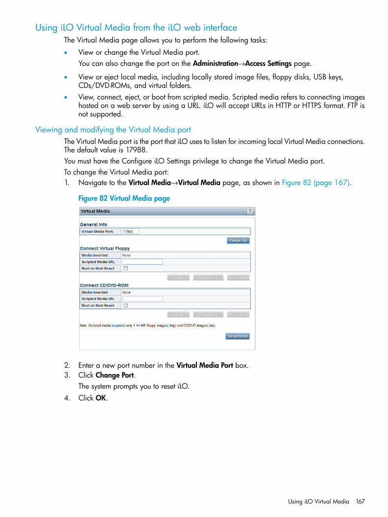
Using iLO Virtual Media from the iLO web interfaceThe Virtual Media page allows you to perform the following tasks:
• View or change the Virtual Media port.You can also change the port on the Administration→Access Settings page.
• View or eject local media, including locally stored image files, floppy disks, USB keys,CDs/DVD-ROMs, and virtual folders.
• View, connect, eject, or boot from scripted media. Scripted media refers to connecting imageshosted on a web server by using a URL. iLO will accept URLs in HTTP or HTTPS format. FTP isnot supported.
Viewing and modifying the Virtual Media portThe Virtual Media port is the port that iLO uses to listen for incoming local Virtual Media connections.The default value is 17988.You must have the Configure iLO Settings privilege to change the Virtual Media port.To change the Virtual Media port:1. Navigate to the Virtual Media→Virtual Media page, as shown in Figure 82 (page 167).
Figure 82 Virtual Media page
2. Enter a new port number in the Virtual Media Port box.3. Click Change Port.
The system prompts you to reset iLO.4. Click OK.
Using iLO Virtual Media 167
Viewing and ejecting local mediaWhen local Virtual Media is connected, the details are listed in the following sections:
• Virtual Floppy/USB Key/Virtual Folder Status
Image Inserted—The Virtual Media type that is connected. Local media is displayed whenlocal media is connected.
◦
◦ Connected—Indicates whether a Virtual Media device is connected.
• Virtual CD/DVD-ROM Status
Image Inserted—The Virtual Media type that is connected. Local media is displayed whenlocal media is connected.
◦
◦ Connected—Indicates whether a Virtual Media device is connected.
To eject local Virtual Media devices, click the Force Eject Media button in the Virtual Floppy/USBKey/Virtual Folder Status section or Virtual CD/DVD-ROM Status section.
NOTE: For blade servers without an iLO license that grants full Virtual Media privileges, youcannot use the Force Eject Media option with a virtual media image that was mounted via URL. Inthis case, the connection is most likely the HP BladeSystem Onboard Administrator DVD Drive.This connection must be disconnected through the Onboard Administrator. An iLO reset will alsoclose the connection.
Connecting scripted mediaYou can connect scripted media from the Virtual Media page. Use the .NET IRC or Java IRC,RIBCL/XML, or the iLO CLI to connect other types of Virtual Media. Scripted media supports only1.44 MB floppy images (.img) and CD/DVD-ROM images (.iso). The image must be locatedon a web server on the same network as iLO.To connect scripted media:1. Navigate to the Virtual Media→Virtual Media page, as shown in Figure 82 (page 167).2. Enter the URL for the scripted media in the Scripted Media URL box in the Connect Virtual
Floppy section (.img files) or the Connect CD/DVD-ROM section (.iso files).3. Select the Boot on Next Reset check box if the server should boot to this image only on the
next server reboot.The image will be ejected automatically on the second server reboot so that the server doesnot boot to this image twice.If this check box is not selected, the image will remain connected until it is manually ejected,and the server will boot to it on all subsequent server resets, if the system boot options areconfigured accordingly.
4. Click Insert Media.5. Optional: To boot to the connected image now, click Server Reset to initiate a server reset.
Viewing and ejecting scripted mediaWhen scripted Virtual Media is connected, the following details are listed in the VirtualFloppy/Virtual Folder Status section and Virtual CD/DVD-ROM Status section:
• Image Inserted—The Virtual Media type that is connected. Scripted media is displayed whenscripted media is connected.
• Connected—Indicates whether a Virtual Media device is connected.
• Image URL—The URL that points to the connected scripted media.
168 Using iLO
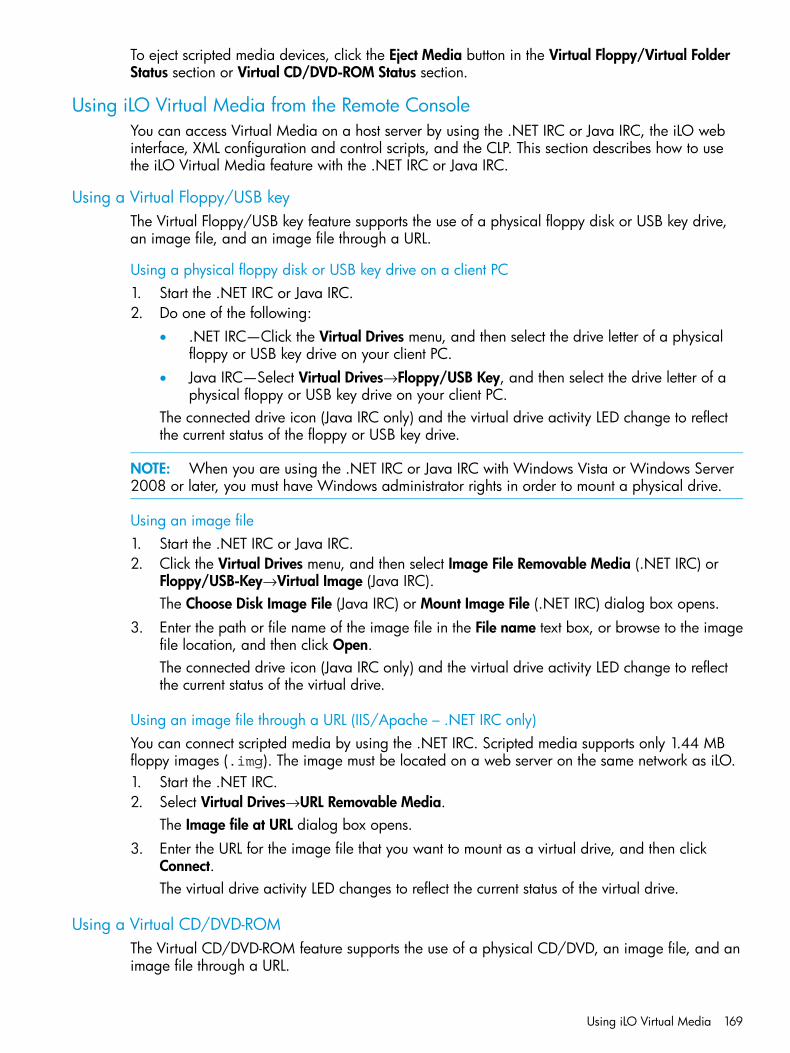
To eject scripted media devices, click the Eject Media button in the Virtual Floppy/Virtual FolderStatus section or Virtual CD/DVD-ROM Status section.
Using iLO Virtual Media from the Remote ConsoleYou can access Virtual Media on a host server by using the .NET IRC or Java IRC, the iLO webinterface, XML configuration and control scripts, and the CLP. This section describes how to usethe iLO Virtual Media feature with the .NET IRC or Java IRC.
Using a Virtual Floppy/USB keyThe Virtual Floppy/USB key feature supports the use of a physical floppy disk or USB key drive,an image file, and an image file through a URL.
Using a physical floppy disk or USB key drive on a client PC1. Start the .NET IRC or Java IRC.2. Do one of the following:
• .NET IRC—Click the Virtual Drives menu, and then select the drive letter of a physicalfloppy or USB key drive on your client PC.
• Java IRC—Select Virtual Drives→Floppy/USB Key, and then select the drive letter of aphysical floppy or USB key drive on your client PC.
The connected drive icon (Java IRC only) and the virtual drive activity LED change to reflectthe current status of the floppy or USB key drive.
NOTE: When you are using the .NET IRC or Java IRC with Windows Vista or Windows Server2008 or later, you must have Windows administrator rights in order to mount a physical drive.
Using an image file1. Start the .NET IRC or Java IRC.2. Click the Virtual Drives menu, and then select Image File Removable Media (.NET IRC) or
Floppy/USB-Key→Virtual Image (Java IRC).The Choose Disk Image File (Java IRC) or Mount Image File (.NET IRC) dialog box opens.
3. Enter the path or file name of the image file in the File name text box, or browse to the imagefile location, and then click Open.The connected drive icon (Java IRC only) and the virtual drive activity LED change to reflectthe current status of the virtual drive.
Using an image file through a URL (IIS/Apache – .NET IRC only)You can connect scripted media by using the .NET IRC. Scripted media supports only 1.44 MBfloppy images (.img). The image must be located on a web server on the same network as iLO.1. Start the .NET IRC.2. Select Virtual Drives→URL Removable Media.
The Image file at URL dialog box opens.3. Enter the URL for the image file that you want to mount as a virtual drive, and then click
Connect.The virtual drive activity LED changes to reflect the current status of the virtual drive.
Using a Virtual CD/DVD-ROMThe Virtual CD/DVD-ROM feature supports the use of a physical CD/DVD, an image file, and animage file through a URL.
Using iLO Virtual Media 169
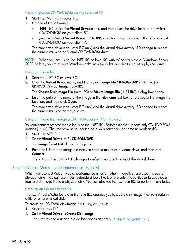
Using a physical CD/DVD-ROM drive on a client PC1. Start the .NET IRC or Java IRC.2. Do one of the following:
• .NET IRC—Click the Virtual Drives menu, and then select the drive letter of a physicalCD/DVD-ROM on your client PC.
• Java IRC—Select Virtual Drives→CD/DVD, and then select the drive letter of a physicalCD/DVD-ROM on your client PC.
The connected drive icon (Java IRC only) and the virtual drive activity LED change to reflectthe current status of the Virtual CD/DVD-ROM drive.
NOTE: When you are using the .NET IRC or Java IRC with Windows Vista or Windows Server2008 or later, you must have Windows administrator rights in order to mount a physical drive.
Using an image file1. Start the .NET IRC or Java IRC.2. Click the Virtual Drives menu, and then select Image File CD-ROM/DVD (.NET IRC) or
CD/DVD→Virtual Image (Java IRC).The Choose Disk Image File (Java IRC) or Mount Image File (.NET IRC) dialog box opens.
3. Enter the path or file name of the image in the File name text box, or browse to the image filelocation, and then click Open.The connected drive icon (Java IRC only) and the virtual drive activity LED change to reflectthe current status of the virtual drive.
Using an image file through a URL (IIS/Apache – .NET IRC only)You can connect scripted media by using the .NET IRC. Scripted media supports only CD/DVD-ROMimages (.iso). The image must be located on a web server on the same network as iLO.1. Start the .NET IRC.2. Select Virtual Drives→URL CD-ROM/DVD.
The Image file at URL dialog box opens.3. Enter the URL for the image file that you want to mount as a virtual drive, and then click
Connect.The virtual drive activity LED changes to reflect the current status of the virtual drive.
Using the Create Media Image feature (Java IRC only)When you use iLO Virtual Media, performance is fastest when image files are used instead ofphysical disks. You can use industry-standard tools like DD to create image files or to copy datafrom a disk image file to a physical disk. You can also use the iLO Java IRC to perform these tasks.
Creating an iLO disk image fileThe iLO Virtual Media feature in the Java IRC enables you to create disk image files from data ina file or on a physical disk.To create an ISO-9660 disk image file (.img or .iso):1. Start the Java IRC.2. Select Virtual Drives →Create Disk Image.
The Create Media Image dialog box opens as shown in Figure 83 (page 171).
170 Using iLO
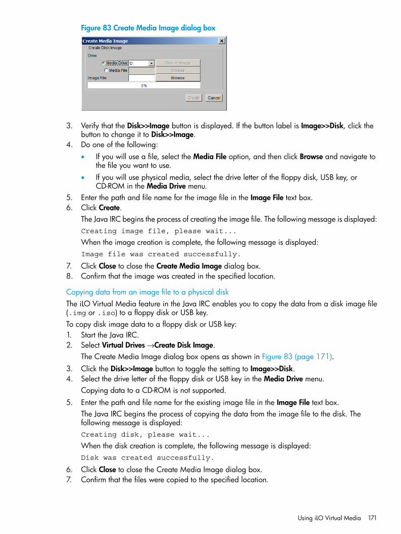
Figure 83 Create Media Image dialog box
3. Verify that the Disk>>Image button is displayed. If the button label is Image>>Disk, click thebutton to change it to Disk>>Image.
4. Do one of the following:• If you will use a file, select the Media File option, and then click Browse and navigate to
the file you want to use.• If you will use physical media, select the drive letter of the floppy disk, USB key, or
CD-ROM in the Media Drive menu.5. Enter the path and file name for the image file in the Image File text box.6. Click Create.
The Java IRC begins the process of creating the image file. The following message is displayed:Creating image file, please wait...
When the image creation is complete, the following message is displayed:Image file was created successfully.
7. Click Close to close the Create Media Image dialog box.8. Confirm that the image was created in the specified location.
Copying data from an image file to a physical diskThe iLO Virtual Media feature in the Java IRC enables you to copy the data from a disk image file(.img or .iso) to a floppy disk or USB key.To copy disk image data to a floppy disk or USB key:1. Start the Java IRC.2. Select Virtual Drives →Create Disk Image.
The Create Media Image dialog box opens as shown in Figure 83 (page 171).3. Click the Disk>>Image button to toggle the setting to Image>>Disk.4. Select the drive letter of the floppy disk or USB key in the Media Drive menu.
Copying data to a CD-ROM is not supported.5. Enter the path and file name for the existing image file in the Image File text box.
The Java IRC begins the process of copying the data from the image file to the disk. Thefollowing message is displayed:Creating disk, please wait...
When the disk creation is complete, the following message is displayed:Disk was created successfully.
6. Click Close to close the Create Media Image dialog box.7. Confirm that the files were copied to the specified location.
Using iLO Virtual Media 171
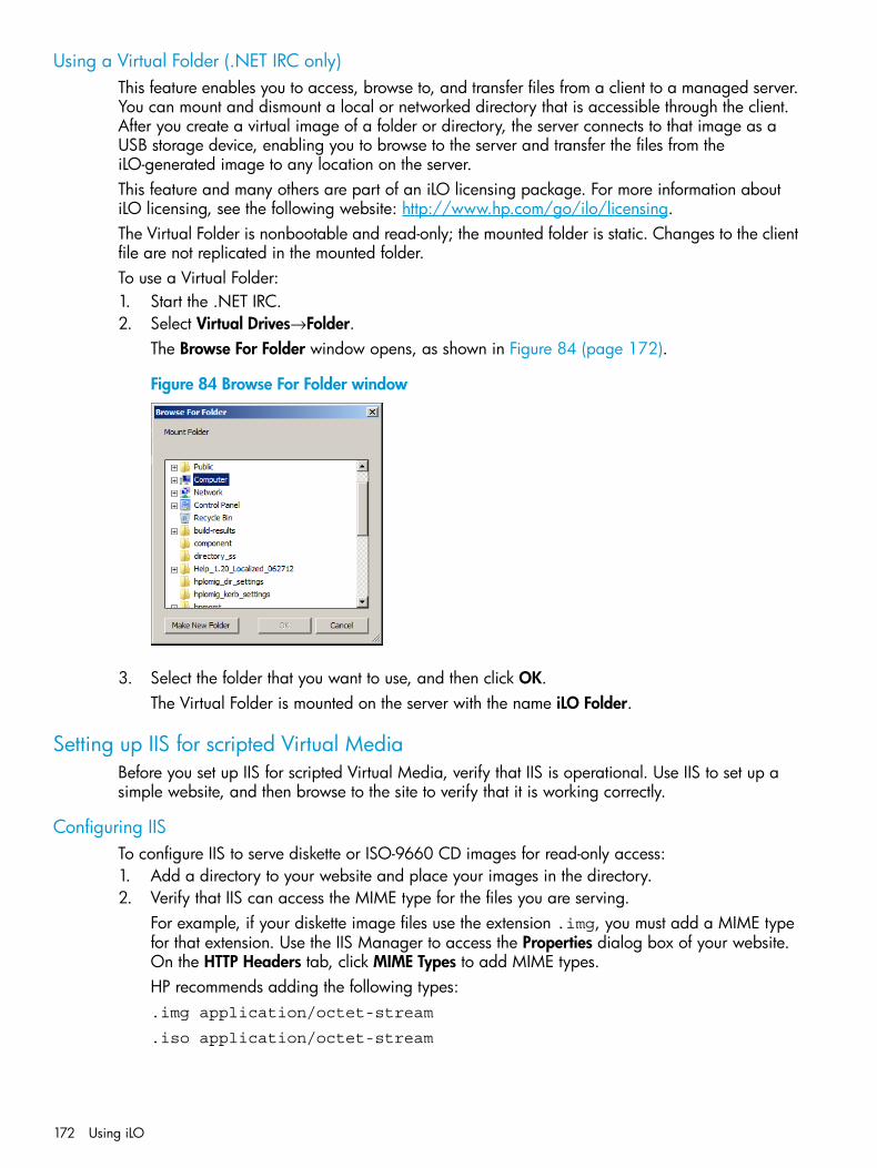
Using a Virtual Folder (.NET IRC only)This feature enables you to access, browse to, and transfer files from a client to a managed server.You can mount and dismount a local or networked directory that is accessible through the client.After you create a virtual image of a folder or directory, the server connects to that image as aUSB storage device, enabling you to browse to the server and transfer the files from theiLO-generated image to any location on the server.This feature and many others are part of an iLO licensing package. For more information aboutiLO licensing, see the following website: http://www.hp.com/go/ilo/licensing.The Virtual Folder is nonbootable and read-only; the mounted folder is static. Changes to the clientfile are not replicated in the mounted folder.To use a Virtual Folder:1. Start the .NET IRC.2. Select Virtual Drives→Folder.
The Browse For Folder window opens, as shown in Figure 84 (page 172).
Figure 84 Browse For Folder window
3. Select the folder that you want to use, and then click OK.The Virtual Folder is mounted on the server with the name iLO Folder.
Setting up IIS for scripted Virtual MediaBefore you set up IIS for scripted Virtual Media, verify that IIS is operational. Use IIS to set up asimple website, and then browse to the site to verify that it is working correctly.
Configuring IISTo configure IIS to serve diskette or ISO-9660 CD images for read-only access:1. Add a directory to your website and place your images in the directory.2. Verify that IIS can access the MIME type for the files you are serving.
For example, if your diskette image files use the extension .img, you must add a MIME typefor that extension. Use the IIS Manager to access the Properties dialog box of your website.On the HTTP Headers tab, click MIME Types to add MIME types.HP recommends adding the following types:.img application/octet-stream
.iso application/octet-stream
172 Using iLO
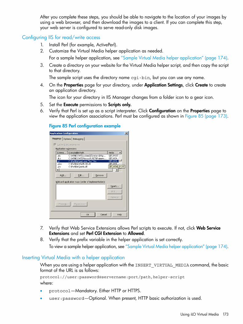
After you complete these steps, you should be able to navigate to the location of your images byusing a web browser, and then download the images to a client. If you can complete this step,your web server is configured to serve read-only disk images.
Configuring IIS for read/write access1. Install Perl (for example, ActivePerl).2. Customize the Virtual Media helper application as needed.
For a sample helper application, see “Sample Virtual Media helper application” (page 174).3. Create a directory on your website for the Virtual Media helper script, and then copy the script
to that directory.The sample script uses the directory name cgi-bin, but you can use any name.
4. On the Properties page for your directory, under Application Settings, click Create to createan application directory.The icon for your directory in IIS Manager changes from a folder icon to a gear icon.
5. Set the Execute permissions to Scripts only.6. Verify that Perl is set up as a script interpreter. Click Configuration on the Properties page to
view the application associations. Perl must be configured as shown in Figure 85 (page 173).
Figure 85 Perl configuration example
7. Verify that Web Service Extensions allows Perl scripts to execute. If not, click Web ServiceExtensions and set Perl CGI Extension to Allowed.
8. Verify that the prefix variable in the helper application is set correctly.To view a sample helper application, see “Sample Virtual Media helper application” (page 174).
Inserting Virtual Media with a helper applicationWhen you are using a helper application with the INSERT_VIRTUAL_MEDIA command, the basicformat of the URL is as follows:protocol://user:password@servername:port/path,helper-script
where:
• protocol—Mandatory. Either HTTP or HTTPS.
• user:password—Optional. When present, HTTP basic authorization is used.
Using iLO Virtual Media 173

• servername—Mandatory. Either the host name or the IP address of the web server.
• port—Optional. A web server on a nonstandard port.
• path—Mandatory. The image file that is being accessed.
• helper-script—Optional. The location of the helper script on IIS web servers.For detailed information about the INSERT_VIRTUAL_MEDIA command, see the HP iLO 4 Scriptingand Command Line Guide.
Sample Virtual Media helper applicationThe following Perl script is an example of a CGI helper application that allows diskette writes onweb servers that cannot perform partial writes. A helper application can be used in conjunctionwith the INSERT_VIRTUAL_MEDIA command to mount a writable disk.When you are using the helper application, the iLO firmware posts a request to this applicationusing the following parameters:
• The file parameter contains the name of the file provided in the original URL.
• The range parameter contains an inclusive range (in hexadecimal) that designates where towrite the data.
• The data parameter contains a hexadecimal string that represents the data to be written.The helper script must transform the file parameter into a path relative to its working directory.This might involve prefixing it with "../," or transforming an aliased URL path into the true path onthe file system. The helper script requires write access to the target file. Diskette image files musthave the appropriate permissions.Example:#!/usr/bin/perl
use CGI;use Fcntl;
## The prefix is used to get from the current working directory to the# location of the image file that you are trying to write#my ($prefix) = "c:/inetpub/wwwroot";my ($start, $end, $len, $decode);
my $q = new CGI(); # Get CGI data
my $file = $q->param('file'); # File to be writtenmy $range = $q->param('range'); # Byte range to be writtenmy $data = $q->param('data'); # Data to be written
## Change the file name appropriately#$file = $prefix . "/" . $file;
## Decode the range#if ($range =~ m/([0-9A-Fa-f]+)-([0-9A-Fa-f]+)/) { $start = hex($1); $end = hex($2); $len = $end - $start + 1;}
#
174 Using iLO
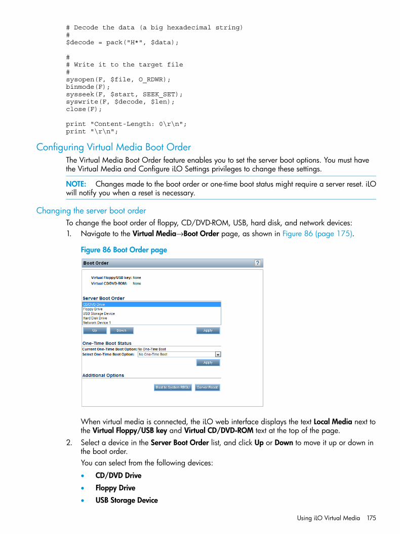
# Decode the data (a big hexadecimal string)#$decode = pack("H*", $data);
## Write it to the target file#sysopen(F, $file, O_RDWR);binmode(F);sysseek(F, $start, SEEK_SET);syswrite(F, $decode, $len);close(F);
print "Content-Length: 0\r\n";print "\r\n";
Configuring Virtual Media Boot OrderThe Virtual Media Boot Order feature enables you to set the server boot options. You must havethe Virtual Media and Configure iLO Settings privileges to change these settings.
NOTE: Changes made to the boot order or one-time boot status might require a server reset. iLOwill notify you when a reset is necessary.
Changing the server boot orderTo change the boot order of floppy, CD/DVD-ROM, USB, hard disk, and network devices:1. Navigate to the Virtual Media→Boot Order page, as shown in Figure 86 (page 175).
Figure 86 Boot Order page
When virtual media is connected, the iLO web interface displays the text Local Media next tothe Virtual Floppy/USB key and Virtual CD/DVD-ROM text at the top of the page.
2. Select a device in the Server Boot Order list, and click Up or Down to move it up or down inthe boot order.You can select from the following devices:
• CD/DVD Drive
• Floppy Drive
• USB Storage Device
Using iLO Virtual Media 175
• Hard Disk Drive
• Network Device <number>, where the server Ethernet card is Network Device 1, andadditional NIC/ALOM cards are Network Device 2, Network Device 3, and so on.
3. Click Apply.
Changing the one-time boot statusTo set the type of media to boot on the next server reset, without changing the predefined bootorder:1. Navigate to the Virtual Media→Boot Order page, as shown in Figure 86 (page 175).2. Select an option from the Select One-Time Boot Option list.
The following options are available:
• No One-Time Boot
• CD/DVD Drive
• Floppy Drive
• USB Storage Device
• Hard Disk Drive
• Network Device3. Click Apply.
The following message appears:Successfully set one-time boot option.The Current One-Time Boot Option value is updated to show the selection.
Using the additional optionsNavigate to the Virtual Media→Boot Order page, as shown in Figure 86 (page 175).
• Click Boot to System RBSU to load the system RBSU on the next server reset.
• Click Server Reset to reboot the server. If a one-time boot option is specified, this setting takesprecedence over the Server Boot Order value.
About server power
Powering on the serverBefore the introduction of the HP ProLiant Gen8 servers, some HP ProLiant servers (particularly MLand DL) could be powered on through the power button within a few seconds after AC power wasconnected. If an AC power loss occurs on HP ProLiant Gen8 servers with iLO 4, approximately30 seconds must elapse before the servers can power on again. The power button will blink,indicating a pending request, if it is pressed during that time.This delay is a result of the iLO firmware loading, authenticating, and booting. iLO processespending power-button requests when initialization is complete. If the server does not lose power,there is no delay. A 30-second delay occurs only during an iLO reset. The power button is disableduntil iLO is ready to manage power.A power-button watchdog allows the user to power on the system using the power button wheniLO does not boot successfully.The iLO firmware monitors and configures power thresholds to support managed-power systems(for example, using HP power capping technology). Multiple system brownout, blackout, andthermal overloads might result when systems are allowed to boot before iLO can manage power.
176 Using iLO
The managed-power state is lost because of AC power loss, so iLO must first boot to a restore stateand allow power-on.
Brownout recoveryA brownout condition occurs when power to a running server is lost momentarily. A brownoutinterrupts the operating system, but does not interrupt the iLO firmware unless it lasts more than 4seconds.iLO detects and recovers from power brownouts. If iLO detects that a brownout has occurred,server power is restored after the power-on delay unless Auto-Power On is set to Always RemainOff. After the brownout recovery, iLO firmware records a Brown-out recovery event in theiLO Event Log.
Graceful shutdownThe ability of the iLO processor to perform a graceful shutdown requires cooperation from theoperating system. To perform a graceful shutdown, the iLO health driver must be loaded. iLOcommunicates with the health driver and uses the appropriate operating system method of shuttingdown the system safely to ensure that data integrity is preserved.If the health driver is not loaded, the iLO processor attempts to use the operating system to performa graceful shutdown through the power button. iLO emulates a physical power-button press (iLOmomentary press) in order to prompt the operating system to shut down gracefully. The behaviorof the operating system depends on its configuration and settings for a power-button press.For more information about the iLO drivers, see “Installing the iLO drivers” (page 22).The Thermal Shutdown option in the system RBSU allows you to disable the automatic shutdownfeature. This configuration allows the disabling of automatic shutdown except in the most extremeconditions where physical damage might result.
Power efficiencyiLO enables you to improve power usage by using High Efficiency Mode. HEM improves the powerefficiency of the system by placing the secondary power supplies in step-down mode. When thesecondary supplies are in step-down mode, the primary supplies provide all DC power to thesystem. The power supplies are more efficient because there are more DC output watts for eachwatt of AC input"
NOTE: HEM is available on nonblade servers only.
When the system draws more than 70% of the maximum power output of the primary supplies,the secondary supplies return to normal operation (that is, they exit step-down mode). When poweruse drops below 60% capacity of the primary supplies, the secondary supplies return to step-downmode. HEM enables you to achieve power consumption equal to the maximum power output ofthe primary and secondary power supplies, while maintaining improved efficiency at lowerpower-usage levels.HEM does not affect power redundancy. If the primary supplies fail, the secondary suppliesimmediately begin supplying DC power to the system, preventing any downtime.You must configure HEM through the RBSU. You cannot modify these settings through iLO. Formore information, see the HP ROM-Based Setup Utility User Guide.The configured HEM settings are displayed on the System Information→Server Power page.
Using iLO Power ManagementiLO Power Management enables you to view and control the power state of the server, monitorpower usage, and modify power settings. The Power Management menu has three options: ServerPower, Power Meter, and Power Settings.
Using iLO Power Management 177
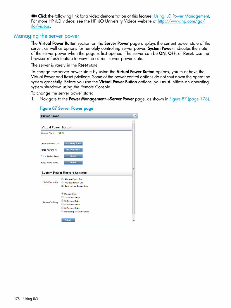
Click the following link for a video demonstration of this feature: Using iLO Power Management.For more HP iLO videos, see the HP iLO University Videos website at http://www.hp.com/go/ilo/videos.
Managing the server powerThe Virtual Power Button section on the Server Power page displays the current power state of theserver, as well as options for remotely controlling server power. System Power indicates the stateof the server power when the page is first opened. The server can be ON, OFF, or Reset. Use thebrowser refresh feature to view the current server power state.The server is rarely in the Reset state.To change the server power state by using the Virtual Power Button options, you must have theVirtual Power and Reset privilege. Some of the power control options do not shut down the operatingsystem gracefully. Before you use the Virtual Power Button options, you must initiate an operatingsystem shutdown using the Remote Console.To change the server power state:1. Navigate to the Power Management→Server Power page, as shown in Figure 87 (page 178).
Figure 87 Server Power page
178 Using iLO

2. Click one of the following buttons:• Momentary Press—The same as pressing the physical power button. If a server is powered
off, a momentary press will turn the server power on.Some operating systems might be configured to initiate a graceful shutdown after amomentary press, or to ignore this event. HP recommends completing a graceful operatingsystem shutdown using system commands before you attempt to shut down using theVirtual Power button.
• Press and Hold—The same as pressing the physical power button for 5 seconds and thenreleasing it.System power is powered off as a result of this operation. Using this option mightcircumvent the graceful shutdown features of the operating system.This option provides the ACPI functionality that some operating systems implement. Theseoperating systems behave differently depending on a short press or long press.
• Reset—Forces a system to warm-boot: CPUs and I/O resources are reset. Using this optioncircumvents the graceful shutdown features of the operating system.
• Cold Boot—Immediately removes power from the system. Processors, memory, and I/Oresources lose main power. The system will restart after approximately 6 seconds. Usingthis option circumvents the graceful shutdown features of the operating system.
NOTE: The Press and Hold, Reset, and Cold Boot options are not available when the serveris powered down.
Configuring the System Power Restore SettingsThe System Power Restore Settings section enables you to control system behavior after power islost. You can also configure these settings using the system RBSU during POST. You must have theConfigure iLO Settings privilege to change the System Power Restore Settings.To change the System Power Restore Settings:1. Navigate to the Power Management→Server Power page, as shown in Figure 87 (page 178).2. Select an Auto Power-On value.
This setting determines how iLO behaves after power is restored—for example, when theserver is plugged in or when a UPS is activated after a power outage.The following options are available:
• Always Power On—Power on the system after the power-on delay (default for BL servers).
• Always Remain Off—The system remains off until directed to power on.
• Restore Last Power State—Return to the server power state when power was lost. If theserver was on, it powers on; if the server was off, it remains off (default for ML, DL, andSL servers).
3. Select a Power-On Delay value.This setting staggers server automatic power-on in a data center. It does not interfere with thepower button. The power-on delay occurs before iLO powers on the server. The iLO firmwarerequires approximately 30 seconds before the server powers on with the minimum delay.The following options are available:
• Minimum Delay—Power-on is delayed by approximately 30 seconds.
• 15 Second Delay—Power-on is delayed by 15 seconds.
• 30 Second Delay—Power-on is delayed by 30 seconds.
• 45 Second Delay—Power-on is delayed by 45 seconds.
Using iLO Power Management 179
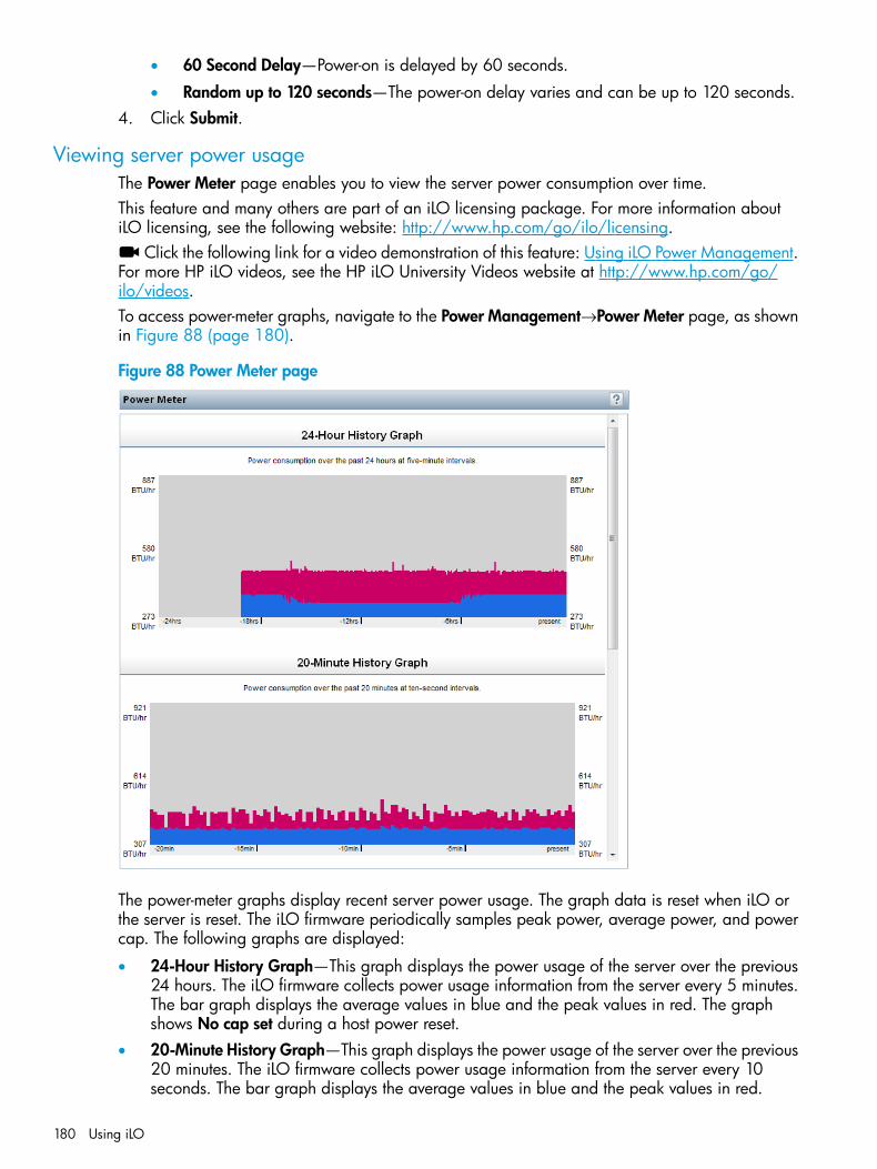
• 60 Second Delay—Power-on is delayed by 60 seconds.
• Random up to 120 seconds—The power-on delay varies and can be up to 120 seconds.4. Click Submit.
Viewing server power usageThe Power Meter page enables you to view the server power consumption over time.This feature and many others are part of an iLO licensing package. For more information aboutiLO licensing, see the following website: http://www.hp.com/go/ilo/licensing.
Click the following link for a video demonstration of this feature: Using iLO Power Management.For more HP iLO videos, see the HP iLO University Videos website at http://www.hp.com/go/ilo/videos.To access power-meter graphs, navigate to the Power Management→Power Meter page, as shownin Figure 88 (page 180).
Figure 88 Power Meter page
The power-meter graphs display recent server power usage. The graph data is reset when iLO orthe server is reset. The iLO firmware periodically samples peak power, average power, and powercap. The following graphs are displayed:
• 24-Hour History Graph—This graph displays the power usage of the server over the previous24 hours. The iLO firmware collects power usage information from the server every 5 minutes.The bar graph displays the average values in blue and the peak values in red. The graphshows No cap set during a host power reset.
• 20-Minute History Graph—This graph displays the power usage of the server over the previous20 minutes. The iLO firmware collects power usage information from the server every 10seconds. The bar graph displays the average values in blue and the peak values in red.
180 Using iLO
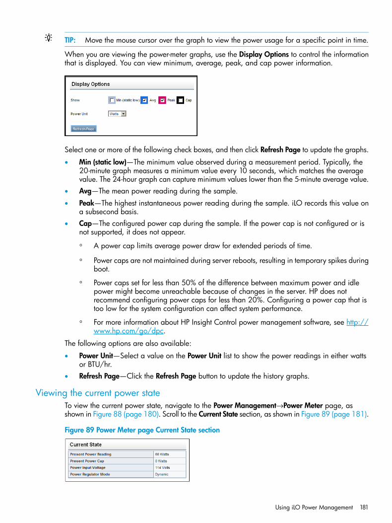
TIP: Move the mouse cursor over the graph to view the power usage for a specific point in time.
When you are viewing the power-meter graphs, use the Display Options to control the informationthat is displayed. You can view minimum, average, peak, and cap power information.
Select one or more of the following check boxes, and then click Refresh Page to update the graphs.
• Min (static low)—The minimum value observed during a measurement period. Typically, the20-minute graph measures a minimum value every 10 seconds, which matches the averagevalue. The 24-hour graph can capture minimum values lower than the 5-minute average value.
• Avg—The mean power reading during the sample.
• Peak—The highest instantaneous power reading during the sample. iLO records this value ona subsecond basis.
• Cap—The configured power cap during the sample. If the power cap is not configured or isnot supported, it does not appear.
◦ A power cap limits average power draw for extended periods of time.
◦ Power caps are not maintained during server reboots, resulting in temporary spikes duringboot.
◦ Power caps set for less than 50% of the difference between maximum power and idlepower might become unreachable because of changes in the server. HP does notrecommend configuring power caps for less than 20%. Configuring a power cap that istoo low for the system configuration can affect system performance.
◦ For more information about HP Insight Control power management software, see http://www.hp.com/go/dpc.
The following options are also available:
• Power Unit—Select a value on the Power Unit list to show the power readings in either wattsor BTU/hr.
• Refresh Page—Click the Refresh Page button to update the history graphs.
Viewing the current power stateTo view the current power state, navigate to the Power Management→Power Meter page, asshown in Figure 88 (page 180). Scroll to the Current State section, as shown in Figure 89 (page 181).
Figure 89 Power Meter page Current State section
Using iLO Power Management 181

The values displayed in the Current State table vary depending on the server type:
• Present Power Reading—The current power reading from the server. This value is displayedfor all HP ProLiant server types.
• Present Power Cap—The configured power cap for the server. This value is 0 if the powercap is not configured. This value is displayed for HP ProLiant ML, DL, and blade servers.
• Power Input Voltage—The supplied input voltage for the server. This value is displayed for HPProLiant ML and DL servers.
• Power Regulator Mode—The configured HP Power Regulator for ProLiant mode. This value isdisplayed for all HP ProLiant server types. For information about the possible settings, see“Configuring power settings” (page 182).
• Power Supply Capacity—The server power capacity. This value is displayed for HP ProLiantSL servers.
• Peak Measured Power—The highest measured power reading. This value is displayed for HPProLiant SL servers.
Viewing the server power historyTo view the server power history, navigate to the Power Management→Power Meter page, asshown in Figure 88 (page 180). Scroll to the Power History section, as shown in Figure 89 (page 181).
Figure 90 Power Meter page Power History section
The Power History table shows power readings from three time periods: 5 minutes, 20 minutes,and 24 hours.
• Average Power—The average of the power readings for the specified time period. If the serverhas not been running for the specified time period, the value is the average of all readingssince the server booted.
• Maximum Power—The maximum power reading from the server for the specified time period.If the server has not been running for the specified time period, the value is the maximum ofall readings since the server booted.
• Minimum Power—The minimum power reading from the server for the specified time period.If the server has not been running for the specified time period, the value is the minimum ofall readings since the server booted.
Configuring power settingsThe Power Settings page enables you to view and control the power management features of theserver. The power management features on this page vary based on the server configuration. Youmust have the Configure iLO Settings privilege to change the values on this page.
Click the following link for a video demonstration of this feature: Using iLO Power Management.For more HP iLO videos, see the HP iLO University Videos website at http://www.hp.com/go/ilo/videos.
Configuring Power Regulator settingsThe HP Power Regulator for ProLiant feature enables iLO to dynamically modify processor frequencyand voltage levels, based on operating conditions, to provide power savings with minimal effect
182 Using iLO
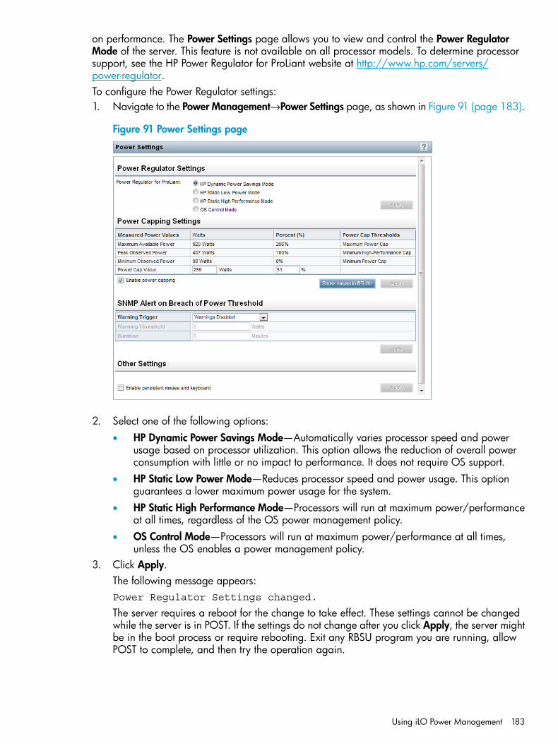
on performance. The Power Settings page allows you to view and control the Power RegulatorMode of the server. This feature is not available on all processor models. To determine processorsupport, see the HP Power Regulator for ProLiant website at http://www.hp.com/servers/power-regulator.To configure the Power Regulator settings:1. Navigate to the Power Management→Power Settings page, as shown in Figure 91 (page 183).
Figure 91 Power Settings page
2. Select one of the following options:• HP Dynamic Power Savings Mode—Automatically varies processor speed and power
usage based on processor utilization. This option allows the reduction of overall powerconsumption with little or no impact to performance. It does not require OS support.
• HP Static Low Power Mode—Reduces processor speed and power usage. This optionguarantees a lower maximum power usage for the system.
• HP Static High Performance Mode—Processors will run at maximum power/performanceat all times, regardless of the OS power management policy.
• OS Control Mode—Processors will run at maximum power/performance at all times,unless the OS enables a power management policy.
3. Click Apply.The following message appears:Power Regulator Settings changed.
The server requires a reboot for the change to take effect. These settings cannot be changedwhile the server is in POST. If the settings do not change after you click Apply, the server mightbe in the boot process or require rebooting. Exit any RBSU program you are running, allowPOST to complete, and then try the operation again.
Using iLO Power Management 183

Configuring power capping settingsThe Power Capping Settings section enables you to view measured power values, set a powercap, and disable power capping.
• The Measured Power Values section lists the following:
Maximum Available Power—The power supply capacity for a nonblade server, or theinitial power-on request value for a blade server
◦
◦ Peak Observed Power—The maximum observed power for the server
◦ Minimum Observed Power—The minimum observed power for the serverDuring POST, the ROM runs two power tests that determine the peak and minimum observedpower values.
• Power capping settings are disabled when the server is part of an Enclosure Dynamic PowerCap. These values are set and modified through using either OA or Insight Control powermanagement.
• Use the Power Cap Thresholds as guidelines for configuring a power cap.
Maximum Power Cap—The maximum power available for the server. The server must notexceed this value.
◦
◦ Minimum High-Performance Cap—The maximum power that the server uses in the currentconfiguration. A power cap set to this value does not affect server performance.
◦ Minimum Power Cap—The minimum power that the server users. A power cap set to thisvalue reduces the server power usage to the minimum, which results in server performancedegradation.
• When a power cap is set, the average power reading of the server must be at or below thepower cap value.
• You cannot use the iLO web interface to configure the power capping settings for SL servers.Use one of the following tools to configure the power capping settings for SL servers:
◦ Power Interface Control Utility—This utility is available at the following website: http://h20000.www2.hp.com/bizsupport/TechSupport/SoftwareDescription.jsp?prodTypeId=15351&prodSeriesId=4324034&swItem=MTX-cb0c48d305d24a4dbe80e5eecc&prodNameId=5037746.
◦ HP ProLiant SL Advanced Power Manager—For more information, see the HP ProLiant SLAdvanced Power Manager User Guide.
To configure a power cap:1. Navigate to the Power Management→Power Settings page, as shown in Figure 91 (page 183).2. Select the Enable power capping check box.3. Enter the Power Cap Value in watts or as a percentage.
Click Show values in BTU/hr to toggle the display between watts and BTU/hr. The percentageis the difference between the maximum and minimum power values. The power cap valuecannot be set below the server minimum power value.
4. Click Apply.
Configuring SNMP alert settingsThe SNMP Alert on Breach of Power Threshold section enables the sending of an SNMP alert whenpower consumption exceeds a defined threshold.To configure the SNMP alert settings:1. Navigate to the Power Management→Power Settings page, as shown in Figure 91 (page 183).
184 Using iLO
2. Select a value in the Warning Trigger list.The warning trigger determines whether warnings are based on peak power consumption,average power consumption, or if they are disabled.
3. Enter a value in the Warning Threshold box.This value sets the power consumption threshold, in watts. If power consumption exceeds thisvalue for the specified time duration, an SNMP alert is triggered.
4. Enter a value in the Duration box.This value sets the length of time, in minutes, that power consumption must remain above thewarning threshold before an SNMP alert is triggered. The maximum duration is 240 minutes,and the duration must be a multiple of 5.
5. Click Apply to save the configuration.
Configuring the persistent mouse and keyboardThe Other Settings section on the Power Settings page allows you to enable or disable the persistentkeyboard and mouse feature.When this feature is enabled, the iLO virtual keyboard and mouse are always connected to theiLO UHCI USB controller. When this feature is disabled, the iLO virtual keyboard and mouse areconnected dynamically to the iLO UHCI controller only when a Remote Console application isopen and connected to iLO. Disabling the feature allows some HP servers to increase power savingsby 15 watts when the server operating system is idle and no virtual USB keyboard and mouse areconnected.For example, the power savings for a 24–hour period might be 15 watts x 24 hours, or 360 watthours (.36 kilowatt-hours).The persistent mouse and keyboard feature is disabled by default.To change the persistent mouse and keyboard setting:1. Navigate to the Power Management→Power Settings page, as shown in Figure 91 (page 183).2. Select or clear the Enable persistent mouse and keyboard check box.3. Click Apply to save the configuration.
Using iLO with Onboard AdministratorOA is the enclosure management processor, subsystem, and firmware base that supports the HPBladeSystem and all managed devices in the enclosure.
Using the Active Onboard AdministratorThe BL c-Class→Active Onboard Administrator page provides general information about the primaryOA in the enclosure in which the iLO processor is located. This page is displayed only when thereis an enclosure. Figure 92 (page 186) shows an example of the page.
Using iLO with Onboard Administrator 185
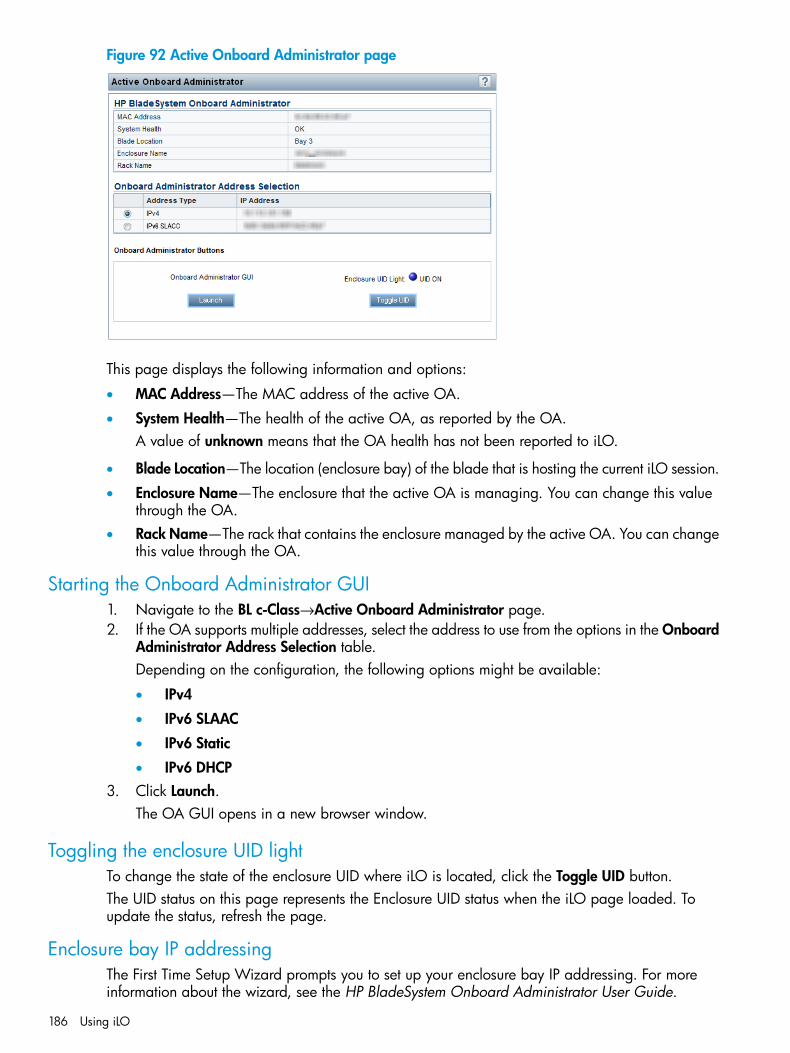
Figure 92 Active Onboard Administrator page
This page displays the following information and options:
• MAC Address—The MAC address of the active OA.
• System Health—The health of the active OA, as reported by the OA.A value of unknown means that the OA health has not been reported to iLO.
• Blade Location—The location (enclosure bay) of the blade that is hosting the current iLO session.
• Enclosure Name—The enclosure that the active OA is managing. You can change this valuethrough the OA.
• Rack Name—The rack that contains the enclosure managed by the active OA. You can changethis value through the OA.
Starting the Onboard Administrator GUI1. Navigate to the BL c-Class→Active Onboard Administrator page.2. If the OA supports multiple addresses, select the address to use from the options in the Onboard
Administrator Address Selection table.Depending on the configuration, the following options might be available:
• IPv4
• IPv6 SLAAC
• IPv6 Static
• IPv6 DHCP3. Click Launch.
The OA GUI opens in a new browser window.
Toggling the enclosure UID lightTo change the state of the enclosure UID where iLO is located, click the Toggle UID button.The UID status on this page represents the Enclosure UID status when the iLO page loaded. Toupdate the status, refresh the page.
Enclosure bay IP addressingThe First Time Setup Wizard prompts you to set up your enclosure bay IP addressing. For moreinformation about the wizard, see the HP BladeSystem Onboard Administrator User Guide.
186 Using iLO
Dynamic Power Capping for server bladesDynamic Power Capping is an iLO feature available for c-Class server blades, and is accessedthrough OA. Dynamic Power Capping is available only if your system hardware platform, BIOS(ROM), and power microcontroller firmware version support this feature. If your system supportsDynamic Power Capping, iLO automatically runs in Dynamic Power Capping mode.For information about the power setting options for c-Class server blades, see the HP BladeSystemOnboard Administrator User Guide.
iLO virtual fanIn c-Class blade servers, OA controls the enclosure fans (also called virtual fans). The iLO firmwarecannot detect these enclosure fans. Instead, the iLO firmware monitors an ambient temperaturesensor located on the blade server. This information is displayed on the iLO web interface, and isretrieved by OA periodically. OA uses the sensor information collected from all iLO processors inthe enclosure to determine enclosure fan speeds.
iLO optionThe iLO - Device Bay <XX> page in OA provides the following links:• Web Administration—Starts the iLO web interface
• Integrated Remote Console—Starts the .NET IRC
• Remote Console—Starts the Java IRCClicking a link on this page opens the requested iLO session in a new window that uses SSO,which does not require an iLO user name or password. If your browser settings prevent newwindows from opening, these links do not work correctly.
Using iLO with Onboard Administrator 187
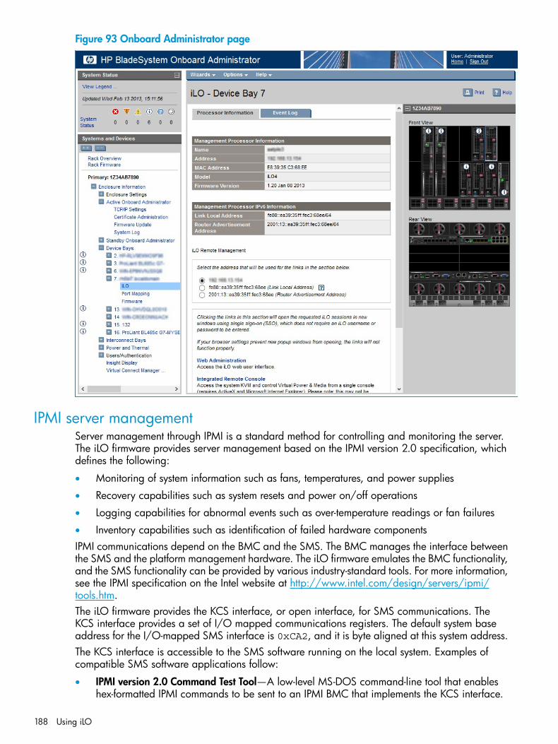
Figure 93 Onboard Administrator page
IPMI server managementServer management through IPMI is a standard method for controlling and monitoring the server.The iLO firmware provides server management based on the IPMI version 2.0 specification, whichdefines the following:
• Monitoring of system information such as fans, temperatures, and power supplies
• Recovery capabilities such as system resets and power on/off operations
• Logging capabilities for abnormal events such as over-temperature readings or fan failures
• Inventory capabilities such as identification of failed hardware componentsIPMI communications depend on the BMC and the SMS. The BMC manages the interface betweenthe SMS and the platform management hardware. The iLO firmware emulates the BMC functionality,and the SMS functionality can be provided by various industry-standard tools. For more information,see the IPMI specification on the Intel website at http://www.intel.com/design/servers/ipmi/tools.htm.The iLO firmware provides the KCS interface, or open interface, for SMS communications. TheKCS interface provides a set of I/O mapped communications registers. The default system baseaddress for the I/O-mapped SMS interface is 0xCA2, and it is byte aligned at this system address.The KCS interface is accessible to the SMS software running on the local system. Examples ofcompatible SMS software applications follow:
• IPMI version 2.0 Command Test Tool—A low-level MS-DOS command-line tool that enableshex-formatted IPMI commands to be sent to an IPMI BMC that implements the KCS interface.
188 Using iLO
You can download this tool from the Intel website at http://www.intel.com/design/servers/ipmi/tools.htm.
• IPMItool—A utility for managing and configuring devices that support the IPMI version 1.5and version 2.0 specifications. IPMItool can be used in a Linux environment. You can downloadthis tool from the IPMItool website at http://ipmitool.sourceforge.net/index.html.
When emulating a BMC for the IPMI interface, iLO supports all mandatory commands listed in theIPMI version 2.0 specification. The SMS should use the methods described in the specification fordetermining which IPMI features are enabled or disabled in the BMC (for example, using the GetDevice ID command).If the server operating system is running, and the iLO health driver is enabled, any IPMI trafficthrough the KCS interface can affect health driver performance and overall system health. Do notissue any IPMI commands through the KCS interface that might have a negative effect on healthdriver monitoring. This restriction includes any command that sets or changes IPMI parameters,such as Set Watchdog Timer and Set BMC Global Enabled. Any IPMI command thatsimply returns data is safe to use, such as Get Device ID and Get Sensor Reading.
Using iLO with HP Insight Control server deploymentHP Insight Control server deployment is integrated with iLO to enable the management of remoteservers and the performance of Remote Console operations, regardless of the state of the operatingsystem or hardware.The deployment server enables you to use the power management features of iLO to power on,power off, or cycle power on the target server. Each time a server connects to the deploymentserver, the deployment server polls the target server to verify that an iLO device is installed. Ifinstalled, the server gathers information, including the DNS name, IP address, and user login name.Security is maintained by requiring the user to enter the correct password for that user name.For more information about HP Insight Control server deployment, see the documentation on theHP Insight Control website at http://www.hp.com/go/insightcontrol.
Viewing remote management tool informationiLO 4 1.30 and later allows remote management through supported tools.The association between iLO 4 and a remote management tool is configured by using the remotemanagement tool. For instructions, see your remote management tool documentation.When iLO is under the control of a remote management tool, the iLO GUI includes the followingenhancements:
• A message similar to the following is displayed on the iLO login page:Warning! Some iLO settings are managed by <Remote Management ToolName>.
Changes made directly in iLO will be out of sync with the centralizedsettings.
• A page called <Remote Management Tool Name> is added to the iLO navigation tree.
Starting a remote management toolWhen iLO is under the control of a remote management tool, use the following procedure to startthe remote manager GUI from iLO.1. Navigate to the <Remote Management Tool Name> page.2. Click Launch.
The remote management tool starts in a separate browser window.
Using iLO with HP Insight Control server deployment 189
5 Integrating HP Systems Insight ManagerThe iLO firmware is integrated with HP SIM in key operating environments, providing a singlemanagement console from a standard web browser. While the operating system is running, youcan establish a connection to iLO by using HP SIM.Integration with HP SIM provides the following:
• Support for SNMP trap delivery to an HP SIM console—The HP SIM console can be configuredto forward SNMP traps to a pager or email address.
• Support for management processors—All iLO devices installed in servers on the network arediscovered in HP SIM as management processors.
• Grouping of iLO management processors—All iLO devices can be grouped logically anddisplayed on one page.
• HP Management Agents or Agentless Management—iLO, combined with AgentlessManagement or the HP Management Agents, provides remote access to system managementinformation through the iLO web interface.
• Support for SNMP management—HP SIM can access Insight Management Agent informationthrough iLO.
HP SIM featuresHP SIM enables you to do the following:
• Identify iLO processors.
• Create an association between an iLO processor and its server.
• Create links between an iLO processor and its server.
• View iLO and server information and status.
• Control the amount of information displayed for iLO.The following sections summarize these features. For detailed information, see the HP SystemsInsight Manager User Guide.
Establishing SSO with HP SIM1. Configure iLO for HP SIM SSO and add HP SIM trusted servers.
For instructions, see “Configuring iLO for HP SSO” (page 65).2. Log in to the HP SIM server that you specified in Step 1, and discover the iLO processor.
After you complete the discovery process, SSO is enabled for iLO.For more information about HP SIM discovery tasks, see the HP Systems Insight Manager UserGuide.
iLO identification and associationHP SIM can identify an iLO processor and create an association between iLO and a server. Youcan configure iLO to respond to HP SIM identification requests by setting the Level of Data Returnedvalue on the Administration→Management page. For more information, see “Configuring InsightManagement integration” (page 97).
Viewing iLO status in HP SIMHP SIM identifies iLO as a management processor. HP SIM displays the management processorstatus on the All Systems page.
190 Integrating HP Systems Insight Manager
The iLO management processor is displayed as an icon on the same row as its host server. Thecolor of the icon represents the status of the management processor.For a list of device statuses, see the HP Systems Insight Manager User Guide.
iLO links in HP SIMFor ease of management, HP SIM creates links to the following:
• iLO and the host server from any System(s) list
• The server from the System page for iLO
• iLO from the System page for the serverThe System(s) list pages display iLO, the server, and the relationship between iLO and the server.
• Click a status icon to display the iLO web interface.
• Click the iLO or server name to display the System page of the device.
Viewing iLO in HP SIM System(s) listsiLO management processors can be viewed in HP SIM. A user who has full configuration rightscan create and use customized system collections to group management processors. For moreinformation, see the HP Systems Insight Manager User Guide.
Receiving SNMP alerts in HP SIMYou can configure iLO to forward alerts from the management agents of the host operating systemand to send iLO alerts to HP SIM.HP SIM supports full SNMP management. iLO supports SNMP trap delivery to HP SIM. You canview the event log, select the event, and view additional information about the alert.Configuring the receipt of SNMP alerts in HP SIM:1. To enable iLO to send SNMP traps, navigate to the Administration→Management page and
configure the settings for SNMP, SNMP alerting, and Insight Management Integration. Enterthe IP address of the HP SIM computer in the SNMP Alert Destination(s) box.For more information, see “Configuring iLO Management settings” (page 87).
2. To discover iLO in HP SIM, configure iLO as a managed device for HP SIM.This enables the NIC interface on iLO to function as a dedicated management port, isolatingmanagement traffic from the NIC interface for the remote host server. For instructions, see theHP Systems Insight Manager User Guide.For major events that are not cleared, iLO traps appear in All Events. To obtain moreinformation about the event, click Event Type.
HP SIM port matchingHP SIM is configured to start an HTTP session to check for iLO at port 80. If you want to changethe port number, you must change it in both iLO and HP SIM.
• To change the port in iLO, navigate to the Administration→Access Settings page, and thenenter the new port number in the Web Server Non-SSL Port box.
• To change the port number in HP SIM, add the port to the config\identification\additionalWsDisc.props file in the HP SIM installation directory. If iLO uses the defaultport (80), you do not need to edit this file.The port entry must be on a single line with the port number first, and with all other itemsidentical to the following example (including capitalization). This example shows the correctentry for discovering iLO at port 55000.
Receiving SNMP alerts in HP SIM 191

55000=iLO 4,,true,false,com.hp.mx.core.tools.identification.mgmtproc.MgmtProcessorParser
Reviewing iLO license information in HP SIMHP SIM displays the license status of the iLO management processors. You can use this informationto determine how many and which iLO devices have an optional license installed.To view license information, select Deploy→License Manager. To ensure that the displayed datais current, run the Identify Systems task for your management processors. For more information,see the HP Systems Insight Manager User Guide.
192 Integrating HP Systems Insight Manager
6 Directory servicesThis chapter describes how to configure iLO to use Kerberos login, schema-free directoryauthentication, and HP extended schema directory authentication.
Directory integration benefitsDirectory integration with iLO provides the following benefits:
• Scalability—The directory can be leveraged to support thousands of users on thousands ofiLO processors.
• Security—Robust user-password policies are inherited from the directory. User-passwordcomplexity, rotation frequency, and expiration are policy examples.
• User accountability—In some environments, users share iLO accounts, which makes it difficultto determine who performed an operation.
• Role-based administration—You can create roles (for example, clerical, remote control of thehost, complete control) and associate users or user groups with those roles. A change to asingle role applies to all users and iLO devices associated with that role.
• Single point of administration—You can use native administrative tools like MMC andConsoleOne to administer iLO users.
• Immediacy—A single change in the directory rolls out immediately to associated iLO processors.This eliminates the need to script this process.
• Simpler credentials—You can use existing user accounts and passwords in the directory withouthaving to record a new set of credentials for iLO.
• Flexibility—You can create a single role for a single user on a single iLO processor, a singlerole for multiple users on multiple iLO processors, or a combination of roles as suited to yourenterprise.
• Compatibility—iLO directory integration supports Active Directory and eDirectory.
• Standards—iLO directory support is based on the LDAP 2.0 standard for secure directoryaccess.
Choosing a directory configuration to use with iLOSome directory configuration practices work better with iLO than others. Before you configure iLOfor directories, you must decide whether to use the schema-free directory integration method orthe HP extended schema directory integration method. Answer the following questions to helpevaluate your directory integration requirements:1. Can you apply schema extensions to your directory?
• No—You are using Active Directory, and your company policy prohibits applyingextensions.No—Directory integration does not fit your environment. Consider deploying an evaluationserver to assess the benefits of directory integration.Use group-based schema-free directory integration. For more information, see “Schema-freedirectory integration” (page 199).
• Yes—Proceed to question 2.
Directory integration benefits 193
2. Is your configuration scalable?• No—Deploy an instance of the schema-free directory integration to evaluate whether this
method meets your policy and procedural requirements. If necessary, you can deploy HPschema directory integration later. For more information, see “Schema-free directoryintegration” (page 199).
• Yes—Use HP schema directory integration. For more information, see “Setting up HPextended schema directory integration” (page 203).
The following questions can help you determine whether your configuration is scalable:
• Are you likely to change the rights or privileges for a group of directory users?
• Will you regularly script iLO changes?
• Do you use more than five groups to control iLO privileges?
For more information, see the comprehensive list of benefits in “Directory integration benefits”(page 193). “Directory-enabled remote management” (page 223) explains how roles, groups, andsecurity are enabled and enforced through directories.
Kerberos supportKerberos support enables a user to log in to iLO without supplying a user name and password ifthe client workstation is logged in to the domain and the user is a member of a directory groupfor which iLO is configured. If the workstation is not logged in to the domain, the user can alsolog in to iLO by using the Kerberos user name and domain password. Kerberos support can beconfigured through the web interface, XML (RIBCL), or SSH (partial support for CLI).Because a trust relationship between iLO and the domain is established by a system administratorbefore user sign-on, any form of authentication (including two-factor authentication) is supported.For instructions on configuring a user to support two-factor authentication, see the server operatingsystem documentation.
Click the following link for a video demonstration of this feature: Setting up Kerberos with iLO4. For more HP iLO videos, see the HP iLO University Videos website: http://www.hp.com/go/ilo/videos.
Domain controller preparationIn a Windows Server environment, Kerberos support is part of the domain controller.
Realm namesThe Kerberos realm name for a DNS domain is usually the domain name converted to uppercase.For example:• Parent domain name: example.net
• Kerberos realm name: EXAMPLE.NET
Computer accountsA computer account must be present and enabled in the domain directory for each iLO account.In Windows, create the user account in the Active Directory Users and Computers snap-in. Forexample:• iLO host name: iloname
• Parent domain name: example.net
• iLO domain name (fully qualified): iloname.example.net
194 Directory services
User accountsA user account must be present and enabled in the domain directory for each user who is allowedto log in to iLO.
Generating a keytabThis section describes how to generate a keytab file for iLO in a Windows environment.The iLO host name that you use for keytab generation must be identical to the configured iLO hostname. iLO host names are case sensitive.1. Use the ktpass command to generate a keytab and set the shared secret.
The command is case sensitive and has special characters.ktpass -out iloname.keytab +rndPass -ptype KRB5_NT_SRV_HST [email protected] -princ HTTP/[email protected]
The output should be similar to the following:
Targeting domain controller: domaincontroller.example.net Using legacy password setting method Successfully mapped HTTP/iloname.example.net to iloname. WARNING: pType and account type do not match. This might cause problems.Key created. Output keytab to iloname.keytab: Keytab version: 0x502 keysize 69 HTTP/[email protected] ptype 3 (KRB5 _NT_SRV_HST) vno 3 etype 0x17 (RC4-HMAC) keylength 16 (0x5a5c7c18ae23559acc2 9d95e0524bf23)
NOTE: The ktpass command might display a message about not being able to set theUPN. This is acceptable because iLO is a service, not a user. You might be prompted toconfirm the password change on the computer object. Click OK to close the window andcontinue creating the keytab file. Do not use the -kvno option of the ktpass command. Thisoption causes the knvo in the keytab file to be out of sync with the kvno in Active Directory.
2. Use the SetSPN command to assign the Kerberos SPN to the computer object. For example:SetSPN -A HTTP/iloname.example.net iloname
If the SetSPN command displays an error message, do the following:a. Use MMC with the ADSIEdit snap-in and find the computer object for iLO.b. Set the DNSHostName property to the iLO DNS name. For example:
cn=iloname,ou=us,ou=clients,dc=example,dc=net
3. Use the SetSPN -L iloname command to display the SPNs and DN for the iLO.Verify that the HTTP/iloname.example.net service is displayed.
NOTE: The SetSPN command might display a message about not being able to set theUPN. This is acceptable because iLO is a service, not a user. You might be prompted toconfirm the password change on the computer object. Click OK to close the window andcontinue creating the keytab file.
Key version numberIf a domain controller OS is reinstalled, the key version number sequence resets. You must regenerateand reinstall the keytab files that iLO uses for devices associated with that domain controller.
Kerberos support 195
Windows VistaTo generate keytab files on Windows Vista, use Microsoft hotfix KB960830 and ktpass.exeversion 6.0.6001.22331 or later.
Universal and global user groups (for authorization)To set permissions in iLO, you must create a group in the domain directory. Users who log in toiLO are granted the sum of the permissions for all groups of which they are a member. Onlyuniversal and global user groups can be used to set permissions. Domain local groups are notsupported.
Configuring iLO for Kerberos loginThis section describes the iLO requirements for Kerberos login. You can configure iLO for Kerberoslogin using the iLO web interface, XML configuration and control scripts, or the CLI, CLP, or SSHinterface.
Using the iLO web interfaceTo configure the iLO parameters by using the web interface:1. Navigate to the Network→iLO Dedicated Network Port or Shared Network Port→General
page to configure the iLO Hostname parameter in the iLO Subsystem Name (Host Name) box.The case of the iLO host name used for keytab generation must be identical to the case of theconfigured iLO host name.For more information, see “Configuring general network settings” (page 76).
2. Navigate to the Administration→Security→Directory page to configure the followingKerberos-specific parameters:• Kerberos Authentication
• Kerberos Realm
• Kerberos KDC Server Address
• Kerberos KDC Server Port
• Kerberos KeytabFor more information about the Kerberos-specific parameters, see “Configuring directorysettings” (page 55).
3. Navigate to the Administration→User Administration page to configure directory groups.Each Directory Group includes a DN, SID, and permissions. For Kerberos login, the SIDs ofgroups of which the user is a member are compared to the SIDs for directory groups for whichiLO is configured. The user is granted the sum of the permissions for all groups of which theuser is a member of.You can only use global and universal groups to set permissions. Domain local groups arenot supported.For more information, see “Administering users” (page 33).
4. Navigate to the Information→Overview page to check the Current iLO Date/Time.For more information, see “Viewing iLO overview information” (page 111).
196 Directory services
5. Navigate to the Administration→Network→SNTP Settings page if you want to change thedate and time.For Kerberos authentication to function properly, the date and time must be synchronizedbetween the iLO processor, the KDC, and the client workstation. Set the date and time in iLOwith the server, or obtain the date and time from the network by enabling the SNTP Settingsfeature in iLO.For more information, see “Configuring SNTP settings” (page 86).
Using XML configuration and control scriptsThe following sample scripts show how to set the iLO parameters for directories:
• Set_Server_Name.xml shows how to set the iLO host name.
• Mod_Schemaless_Directory.xml shows how to configure directory groups.
• Mod_Network_Settings.xml shows how to configure SNTP settings.
• Mod_Kerberos_Config.xml shows how to configure Kerberos-specific parameters.
NOTE: You can download sample XML scripts from http://www.hp.com/support/ilo4. For moreinformation, see the HP iLO 4 Scripting and Command Line Guide.
Using the CLI, CLP, or SSH interfaceTo configure the iLO parameters by using the CLI, CLP, or SSH interface:
• iLO Hostname—You can change the iLO host name in the Hostname property of the/map1/dnsendpt1 target.
• Directory groups—You can configure directory group names and permissions in the propertiesof the /map1/oemhp_dircfg1 target. The group SIDs cannot be configured through thisinterface.
• iLO Date/Time, SNTP Settings—The current date and time and the SNTP settings cannot bedisplayed through this interface.
• Kerberos-specific configuration parameters—You can configure Kerberos parameters in theproperties of the oemhp_dircfg1, target.
NOTE: For more information about configuring the iLO parameters by using the CLI, CLP, orSSH, see the HP iLO 4 Scripting and Command Line Guide.
Time requirementTo log in to Kerberos successfully, the date and time of the iLO server, the client running the webbrowser, and the servers that are performing the authentication must be within 5 minutes of oneanother. To do this, synchronize the times of all servers.
Configuring single sign-onUsers who are allowed to log in to iLO must be members of the groups for which permissions areassigned. For Windows clients, locking and unlocking the workstation refreshes the credentialsthat are used to log in to iLO. Home versions of the Windows operating system do not supportKerberos login.
Internet ExplorerThis section describes the procedure for enabling single sign-on with Internet Explorer. The followingsteps enable login if Active Directory is configured correctly for iLO, and iLO is configured correctlyfor Kerberos login.
Kerberos support 197
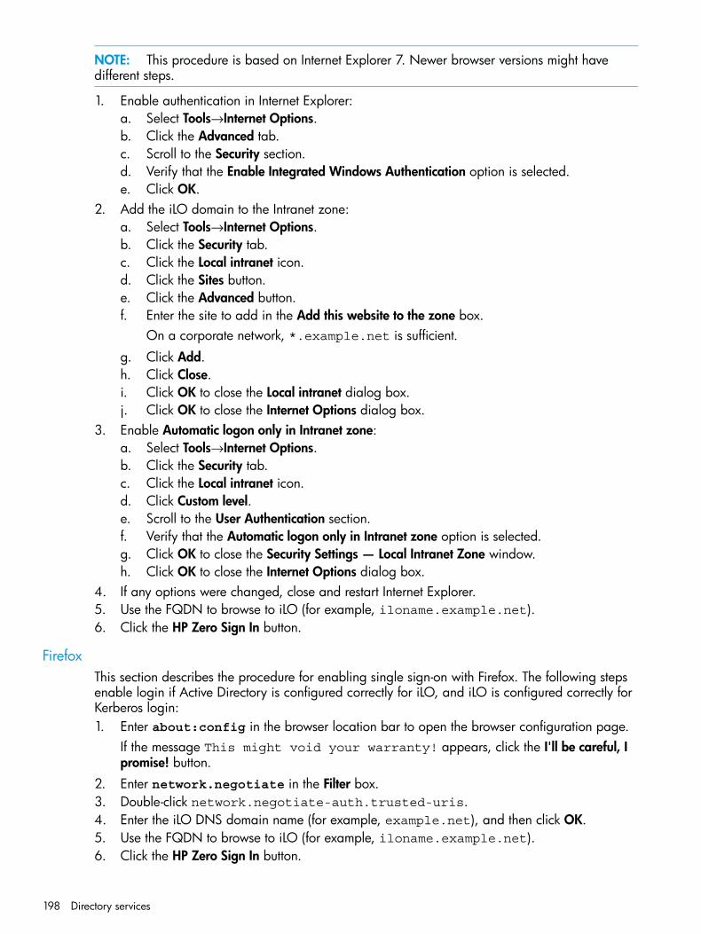
NOTE: This procedure is based on Internet Explorer 7. Newer browser versions might havedifferent steps.
1. Enable authentication in Internet Explorer:a. Select Tools→Internet Options.b. Click the Advanced tab.c. Scroll to the Security section.d. Verify that the Enable Integrated Windows Authentication option is selected.e. Click OK.
2. Add the iLO domain to the Intranet zone:a. Select Tools→Internet Options.b. Click the Security tab.c. Click the Local intranet icon.d. Click the Sites button.e. Click the Advanced button.f. Enter the site to add in the Add this website to the zone box.
On a corporate network, *.example.net is sufficient.
g. Click Add.h. Click Close.i. Click OK to close the Local intranet dialog box.j. Click OK to close the Internet Options dialog box.
3. Enable Automatic logon only in Intranet zone:a. Select Tools→Internet Options.b. Click the Security tab.c. Click the Local intranet icon.d. Click Custom level.e. Scroll to the User Authentication section.f. Verify that the Automatic logon only in Intranet zone option is selected.g. Click OK to close the Security Settings — Local Intranet Zone window.h. Click OK to close the Internet Options dialog box.
4. If any options were changed, close and restart Internet Explorer.5. Use the FQDN to browse to iLO (for example, iloname.example.net).6. Click the HP Zero Sign In button.
FirefoxThis section describes the procedure for enabling single sign-on with Firefox. The following stepsenable login if Active Directory is configured correctly for iLO, and iLO is configured correctly forKerberos login:1. Enter about:config in the browser location bar to open the browser configuration page.
If the message This might void your warranty! appears, click the I'll be careful, Ipromise! button.
2. Enter network.negotiate in the Filter box.3. Double-click network.negotiate-auth.trusted-uris.4. Enter the iLO DNS domain name (for example, example.net), and then click OK.5. Use the FQDN to browse to iLO (for example, iloname.example.net).6. Click the HP Zero Sign In button.
198 Directory services
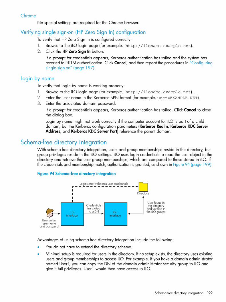
ChromeNo special settings are required for the Chrome browser.
Verifying single sign-on (HP Zero Sign In) configurationTo verify that HP Zero Sign In is configured correctly:1. Browse to the iLO login page (for example, http://iloname.example.net).2. Click the HP Zero Sign In button.
If a prompt for credentials appears, Kerberos authentication has failed and the system hasreverted to NTLM authentication. Click Cancel, and then repeat the procedures in “Configuringsingle sign-on” (page 197).
Login by nameTo verify that login by name is working properly:1. Browse to the iLO login page (for example, http://iloname.example.net).2. Enter the user name in the Kerberos SPN format (for example, [email protected]).3. Enter the associated domain password.
If a prompt for credentials appears, Kerberos authentication has failed. Click Cancel to closethe dialog box.Login by name might not work correctly if the computer account for iLO is part of a childdomain, but the Kerberos configuration parameters (Kerberos Realm, Kerberos KDC ServerAddress, and Kerberos KDC Server Port) reference the parent domain.
Schema-free directory integrationWith schema-free directory integration, users and group memberships reside in the directory, butgroup privileges reside in the iLO settings. iLO uses login credentials to read the user object in thedirectory and retrieve the user group memberships, which are compared to those stored in iLO. Ifthe credentials and membership match, authorization is granted, as shown in Figure 94 (page 199).
Figure 94 Schema-free directory integration
User entersuser name
and password
iLOinterface
Credentialstranslatedto a DN
Login script validates user credentials
User found inthe directory
and verified inthe iLO groups
Directory
iLOinterface
Advantages of using schema-free directory integration include the following:
• You do not have to extend the directory schema.
• Minimal setup is required for users in the directory. If no setup exists, the directory uses existingusers and group memberships to access iLO. For example, if you have a domain administratornamed User1, you can copy the DN of the domain administrator security group to iLO andgive it full privileges. User1 would then have access to iLO.
Schema-free directory integration 199
Using schema-free directory integration has the following disadvantage:
• Group privileges are administered on each iLO. However, this disadvantage has minimalimpact because group privileges rarely change, and the task of changing group membershipis administered in the directory and not on each iLO. HP provides tools that enable you tomake changes to a large number of iLOs at the same time.
Setting up schema-free directory integrationIf you want to use the schema-free directory integration method, your system must meet theprerequisites described in “Active Directory prerequisites” (page 200).
Active Directory prerequisitesSSL must be enabled at the directory level. To enable SSL, install a certificate for the domain inActive Directory. iLO communicates with the directory only over a secure SSL connection.To validate the setup, you must have the directory DN of at least one user and the DN of a securitygroup that the user is a member of.
Introduction to Certificate ServicesCertificate Services is used to issue signed digital certificates to network hosts. The certificates areused to establish SSL connections with the host and verify the authenticity of the host.Installing Certificate Services enables Active Directory to receive a certificate that allows iLOprocessors to connect to the directory service. Without a certificate, iLO cannot connect to thedirectory service.Each directory service that you want iLO to connect to must be issued a certificate. If you installan Enterprise Certificate Service, Active Directory can automatically request and install certificatesfor all Active Directory controllers on the network.
Installing Certificate ServicesUse the following procedure for Windows Server 2008:1. Navigate to Server Manager.2. Click Roles in the left pane.3. Click Add Roles.4. Select Active Directory Certificate Services.5. Follow the onscreen instructions. If you are not sure what values to use, accept the default
values.
Verifying Certificate ServicesBecause management processors communicate with Active Directory by using SSL, you must createa certificate or install Certificate Services. You must install an enterprise CA because you will issuecertificates to objects in your organizational domain.To verify that Certificate Services is installed, select Start→Programs→AdministrativeTools→Certification Authority. An error message appears if Certificate Services is not installed.
Configuring Automatic Certificate RequestTo specify that a certificate be issued to the server:1. Select Start→Run, and then enter mmc.2. Select File→Add/Remove Snap-in.3. To add the snap-in to MMC, select Group Policy Object, and then click Add.4. Click Browse, and then select the Default Domain Policy object. Click OK.5. Click Finish, and then click Close and OK to close the remaining dialog boxes.6. Expand Computer Configuration→Windows Settings→Security Settings→Public Key.
200 Directory services
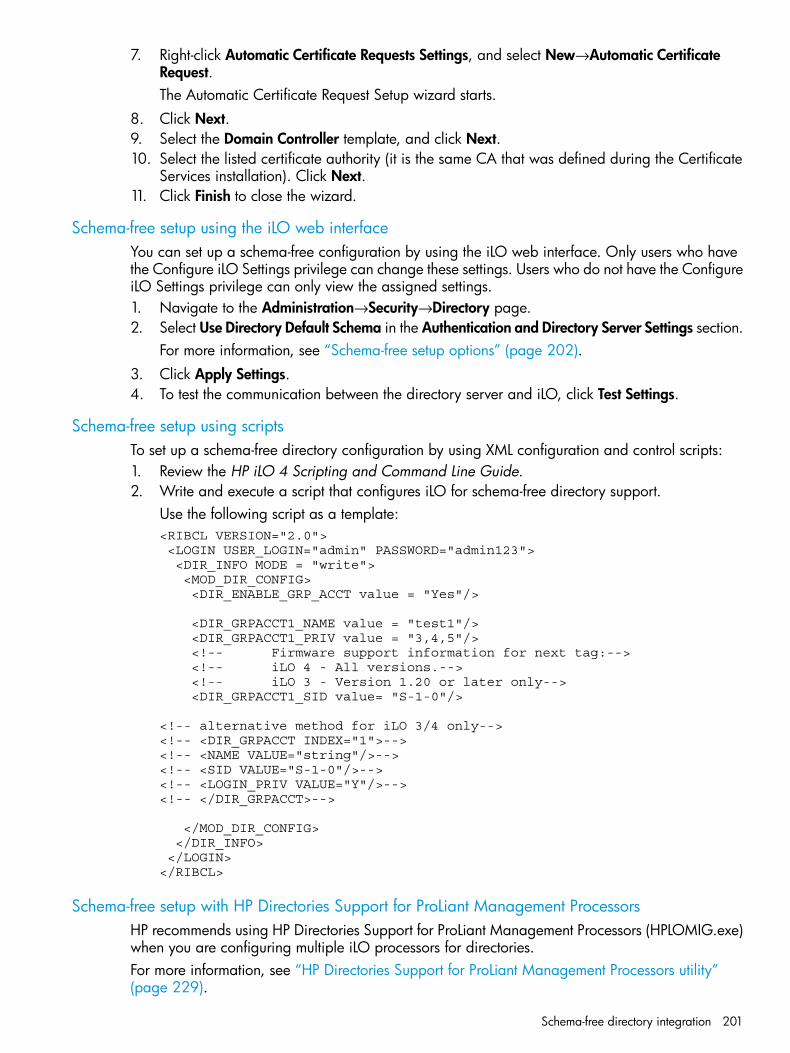
7. Right-click Automatic Certificate Requests Settings, and select New→Automatic CertificateRequest.The Automatic Certificate Request Setup wizard starts.
8. Click Next.9. Select the Domain Controller template, and click Next.10. Select the listed certificate authority (it is the same CA that was defined during the Certificate
Services installation). Click Next.11. Click Finish to close the wizard.
Schema-free setup using the iLO web interfaceYou can set up a schema-free configuration by using the iLO web interface. Only users who havethe Configure iLO Settings privilege can change these settings. Users who do not have the ConfigureiLO Settings privilege can only view the assigned settings.1. Navigate to the Administration→Security→Directory page.2. Select Use Directory Default Schema in the Authentication and Directory Server Settings section.
For more information, see “Schema-free setup options” (page 202).3. Click Apply Settings.4. To test the communication between the directory server and iLO, click Test Settings.
Schema-free setup using scriptsTo set up a schema-free directory configuration by using XML configuration and control scripts:1. Review the HP iLO 4 Scripting and Command Line Guide.2. Write and execute a script that configures iLO for schema-free directory support.
Use the following script as a template:<RIBCL VERSION="2.0"> <LOGIN USER_LOGIN="admin" PASSWORD="admin123"> <DIR_INFO MODE = "write"> <MOD_DIR_CONFIG> <DIR_ENABLE_GRP_ACCT value = "Yes"/>
<DIR_GRPACCT1_NAME value = "test1"/> <DIR_GRPACCT1_PRIV value = "3,4,5"/> <!-- Firmware support information for next tag:--> <!-- iLO 4 - All versions.--> <!-- iLO 3 - Version 1.20 or later only--> <DIR_GRPACCT1_SID value= "S-1-0"/>
<!-- alternative method for iLO 3/4 only--><!-- <DIR_GRPACCT INDEX="1">--><!-- <NAME VALUE="string"/>--><!-- <SID VALUE="S-1-0"/>--><!-- <LOGIN_PRIV VALUE="Y"/>--><!-- </DIR_GRPACCT>-->
</MOD_DIR_CONFIG> </DIR_INFO> </LOGIN></RIBCL>
Schema-free setup with HP Directories Support for ProLiant Management ProcessorsHP recommends using HP Directories Support for ProLiant Management Processors (HPLOMIG.exe)when you are configuring multiple iLO processors for directories.For more information, see “HP Directories Support for ProLiant Management Processors utility”(page 229).
Schema-free directory integration 201
Schema-free setup optionsThe schema-free setup options are the same, regardless of the method you use to configure thedirectory.To review the available methods, see “Schema-free setup using the iLO web interface” (page 201),“Schema-free setup using scripts” (page 201), and “Schema-free setup with HP Directories Supportfor ProLiant Management Processors” (page 201).After you enable directories and select the schema-free option, you have the following options:
Minimum login flexibility
• Enter the directory server DNS name or IP address and LDAP port. Typically, the LDAP portfor an SSL connection is 636.
• Enter the DN for at least one group. This group can be a security group (for example,CN=Administrators,CN=Builtin,DC=HP,DC=com) or any other group as long as theintended iLO users are members of the group.With a minimum configuration, you can log in to iLO by using your full DN and password.You must be a member of a group that iLO recognizes.
Better login flexibilityIn addition to the minimum settings, enter at least one directory user context.At login time, the login name and user context are combined to make the user DN. For example,if the user logs in as JOHN.SMITH, and a user context is set up as CN=USERS,DC=HP,DC=COM,the DN that iLO tries is CN=JOHN.SMITH,CN=USERS,DC=HP,DC=COM.
Maximum login flexibilityConfigure iLO with a DNS name, and not an IP address, for the directory server network address.The DNS name must be resolvable to an IP address from both iLO and the client system.Configuring iLO with maximum login flexibility enables you to log in using your full DN andpassword, your name as it appears in the directory, NetBIOS format (domain/login_name), oremail format (login_name@domain).In some cases, the maximum login flexibility option might not work. For example, if the client andiLO are in different DNS domains, one of the two might not be able to resolve the directory servername to an IP address.
Schema-free nested groupsMany organizations have users and administrators arranged in groups. This arrangement of existinggroups is convenient because you can associate them with one or more iLO management roleobjects. When iLO devices are associated with the role objects, you can use the administratorcontrols to access the devices associated with the role by adding or deleting members from thegroups.When using Microsoft Active Directory, you can place one group in another group to create anested group. Role objects are considered groups and can include other groups directly. You canadd the existing nested group directly to the role and assign the appropriate rights and restrictions.You can add new users to either the existing group or the role.In schema-free integration, users who are indirect members (a member of a group that is a nestedgroup of the primary group) are allowed to log in to iLO.When you are using trustee or directory rights assignments to extend role membership, users mustbe able to read the object that represents the iLO device. Some environments require that thetrustees of a role also be read trustees of the object to successfully authenticate users.
202 Directory services
Setting up HP extended schema directory integrationWhen you are using HP schema directory integration, iLO supports both Active Directory andeDirectory. However, these directory services require that the schema be extended.
Features supported by HP schema directory integrationUsing the HP schema enables you to do the following:
• Authenticate users from a shared, consolidated, scalable user database.
• Control user privileges (authorization) by using the directory service.
• Use roles in the directory service for group-level administration of iLO management processorsand iLO users.
A schema administrator must complete the task of extending the schema. The local user databaseis retained. You can decide not to use directories, to use a combination of directories and localaccounts, or to use directories exclusively for authentication.
NOTE: When you are connected through the Diagnostics Port, the directory server is not available.You log in using a local account.
Advantages of using the HP extended schema include the following:
• There is more flexibility in controlling access. For example, access can be limited to a time ofday or a certain range of IP addresses.
• Groups are maintained in the directory, not on each iLO.
Setting up directory servicesTo successfully implement directory-enabled management on any iLO management processor:1. Plan
Review the following sections:
• Directory services. For more information, see “Directory services” (page 193).
• Directory-enabled remote management. For more information, see “Directory-enabledremote management” (page 223).
• Directory services schema. For more information, see “Directory services schema”(page 273).
2. Installa. Download the HP Directories Support for ProLiant Management Processors package that
contains the schema installer, the management snap-in installer, and the migration utilitiesfrom http://www.hp.com/support/ilo4.
b. Run the schema installer once to extend the schema.c. Run the management snap-in installer and install the appropriate snap-in for your directory
service on one or more management workstations.3. Update
a. Set directory server settings and the DN of the management processor objects on theDirectory Settings page in the iLO web interface. For more information, see “Configuringdirectory settings” (page 55).
b. If you are using the schema-free integration or Kerberos Zero Sign In, configure directorygroups. For more information, see “Administering users” (page 33).
Setting up HP extended schema directory integration 203
4. Managea. Create a management device object and a role object by using the snap-in.b. Assign rights to the role object, as necessary, and associate the role with the management
device object.c. Add users to the role object.For more information about managing the directory service, see “Directory-enabled remotemanagement” (page 223). Examples are available in “Directory services for Active Directory”(page 207) and “Directory services for eDirectory” (page 215).
5. Handle exceptionsiLO migration utilities are easier to use with a single role. If you plan to create multiple rolesin the directory, you might need to use directory scripting utilities, like LDIFDE or VBScriptutilities. These utilities create complex role associations. For more information, see “Using bulkimport tools” (page 229).
After the schema has been extended, you can complete the directory services setup by using HPmigration utilities, which are included in the HP Directories Support for ProLiant ManagementProcessors package.
Schema documentationTo assist with the planning and approval process, HP provides documentation about the changesmade to the schema during the schema setup process. To review the changes made to your existingschema, see “Directory services schema” (page 273).
Directory services supportiLO software is designed to run with the Microsoft Active Directory Users and Computers snap-inor the Novell ConsoleOne management tools, enabling you to manage user accounts through thedirectory.iLO supports the following directory services for HP schema directory integration:
• Microsoft Active Directory
• Microsoft Windows Server 2008 Active Directory
• Novell eDirectoryThis solution makes no distinction between eDirectory running on Linux or eDirectory runningon Windows. eDirectory schema extension requires Java 1.4.0 or later for SSL authentication.
Schema required softwareiLO requires specific software that extends the schema and provides snap-ins to manage the iLOnetwork. The HP Directories Support for ProLiant Management Processors package contains theschema installer and the management snap-in installer, as shown in Figure 95 (page 205). You candownload the software from http://www.hp.com/support/ilo4.
204 Directory services
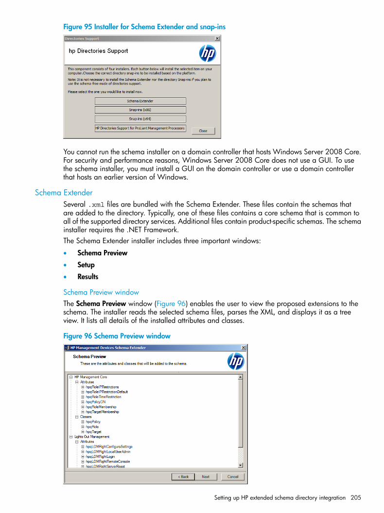
Figure 95 Installer for Schema Extender and snap-ins
You cannot run the schema installer on a domain controller that hosts Windows Server 2008 Core.For security and performance reasons, Windows Server 2008 Core does not use a GUI. To usethe schema installer, you must install a GUI on the domain controller or use a domain controllerthat hosts an earlier version of Windows.
Schema ExtenderSeveral .xml files are bundled with the Schema Extender. These files contain the schemas thatare added to the directory. Typically, one of these files contains a core schema that is common toall of the supported directory services. Additional files contain product-specific schemas. The schemainstaller requires the .NET Framework.The Schema Extender installer includes three important windows:
• Schema Preview
• Setup
• Results
Schema Preview windowThe Schema Preview window (Figure 96) enables the user to view the proposed extensions to theschema. The installer reads the selected schema files, parses the XML, and displays it as a treeview. It lists all details of the installed attributes and classes.
Figure 96 Schema Preview window
Setting up HP extended schema directory integration 205
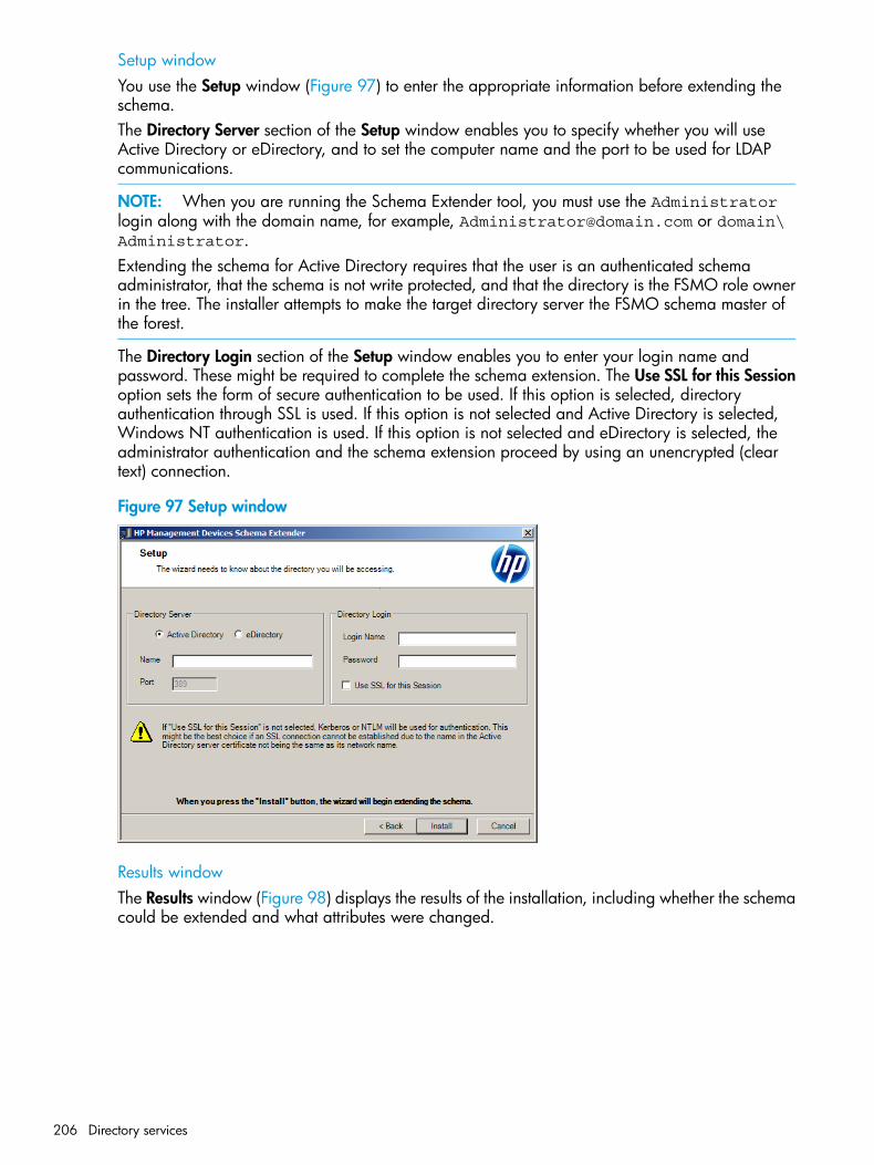
Setup windowYou use the Setup window (Figure 97) to enter the appropriate information before extending theschema.The Directory Server section of the Setup window enables you to specify whether you will useActive Directory or eDirectory, and to set the computer name and the port to be used for LDAPcommunications.
NOTE: When you are running the Schema Extender tool, you must use the Administratorlogin along with the domain name, for example, [email protected] or domain\Administrator.Extending the schema for Active Directory requires that the user is an authenticated schemaadministrator, that the schema is not write protected, and that the directory is the FSMO role ownerin the tree. The installer attempts to make the target directory server the FSMO schema master ofthe forest.
The Directory Login section of the Setup window enables you to enter your login name andpassword. These might be required to complete the schema extension. The Use SSL for this Sessionoption sets the form of secure authentication to be used. If this option is selected, directoryauthentication through SSL is used. If this option is not selected and Active Directory is selected,Windows NT authentication is used. If this option is not selected and eDirectory is selected, theadministrator authentication and the schema extension proceed by using an unencrypted (cleartext) connection.
Figure 97 Setup window
Results windowThe Results window (Figure 98) displays the results of the installation, including whether the schemacould be extended and what attributes were changed.
206 Directory services
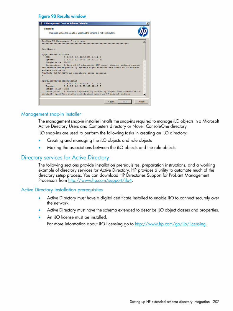
Figure 98 Results window
Management snap-in installerThe management snap-in installer installs the snap-ins required to manage iLO objects in a MicrosoftActive Directory Users and Computers directory or Novell ConsoleOne directory.iLO snap-ins are used to perform the following tasks in creating an iLO directory:
• Creating and managing the iLO objects and role objects
• Making the associations between the iLO objects and the role objects
Directory services for Active DirectoryThe following sections provide installation prerequisites, preparation instructions, and a workingexample of directory services for Active Directory. HP provides a utility to automate much of thedirectory setup process. You can download HP Directories Support for ProLiant ManagementProcessors from http://www.hp.com/support/ilo4.
Active Directory installation prerequisites
• Active Directory must have a digital certificate installed to enable iLO to connect securely overthe network.
• Active Directory must have the schema extended to describe iLO object classes and properties.
• An iLO license must be installed.For more information about iLO licensing go to http://www.hp.com/go/ilo/licensing.
Setting up HP extended schema directory integration 207
• Installing directory services for iLO requires extending the Active Directory schema. An ActiveDirectory schema administrator must extend the schema.
• directory services for iLO uses LDAP over SSL to communicate with the directory servers. Beforeyou install snap-ins and schema for Active Directory, read and have available the followingdocumentation:
◦ Microsoft Knowledge Base ArticlesThese articles are available at http://support.microsoft.com/.
– 321051 Enabling LDAP over SSL with a Third-Party Certificate Authority
– 299687 MS01-036: Function Exposed By Using LDAP over SSL Could EnablePasswords to Be Changed
◦ iLO requires a secure connection to communicate with the directory service. This connectionrequires the installation of the Microsoft CA. For more information, see the MicrosoftKnowledge Base Article 321051: How to Enable LDAP over SSL with a Third-PartyCertification Authority.
Installing Active Directory
For the schema-free configuration1. Disable IPv6, and then install Active Directory, DNS, and the root CA to Windows Server
2008.2. Log in to iLO and enter the directory settings and directory user contexts on the
Administration→Security→Directory page.For more information, see “Configuring directory settings” (page 55).
3. Click Apply Settings to save the changes.4. Click the Administer Groups button, and then create directory groups for the iLO users.
For more information, see “Administering users” (page 33).5. Navigate to the iLO Dedicated Network Port or Shared Network Port General Settings page,
and then enter the environment settings in the Domain Name and Primary DNS server boxes.For more information, see “Configuring IPv4 settings” (page 81).
For HP extended schema1. Disable IPv6, and then install Active Directory, DNS, and the root CA to Windows Server
2008.2. Verify that version 2.0 or later of the .NET Framework is installed. This software is required
by the iLO LDAP component.3. Install the latest HP Directories Support for ProLiant Management Processors software from
http://www.hp.com/support/ilo4.4. Extend the schema by using the Schema Extender.
For more information, see “Schema required software” (page 204).5. Install the HP LDAP component snap-ins.
For more information, see “Schema required software” (page 204).6. Create the HP device and HP role.7. Log in to iLO and enter the directory settings and directory user contexts on the
Administration→Security→Directory page.For more information, see “Configuring directory settings” (page 55).
208 Directory services
8. Navigate to the iLO Dedicated Network Port or Shared Network Port General Settings page,and then enter the environment settings in the Domain Name and Primary DNS server boxes.For more information, see “Configuring iLO network settings” (page 73).
NOTE: The LDAP component does not work with a Windows Server 2008 Core installation.
Snap-in installation and initialization for Active Directory1. Run the snap-in installation application to install the snap-ins.2. Configure the directory service to have the appropriate objects and relationships for iLO
management.a. Use the management snap-ins from HP to create iLO, policy, admin, and user role objects.b. Use the management snap-ins from HP to build associations between the iLO object, the
policy object, and the role object.c. Point the iLO object to the admin and user role objects. (Admin and user roles automatically
point back to the iLO object.)For more information about iLO objects, see “Directory services objects” (page 210).
At a minimum, you must create the following:
• One role object that contains one or more users and one or more iLO objects
• One iLO object that corresponds to each iLO management processor that uses the directory
Creating and configuring directory objects for use with iLO in Active DirectoryThe following example describes how to set up roles and HP devices in an enterprise directorywith the domain testdomain.local. This domain consists of two organizational units, Rolesand iLOs.
TIP: For more information about using the Active Directory snap-ins, see “Active Directory snap-ins”(page 211).
Create an organizational unit that contains the iLO devices managed by the domain.1. Use the HP-provided Active Directory Users and Computers snap-ins to create Lights-Out
Management objects in the iLOs organizational unit for several iLO devices.a. Right-click the iLOs organizational unit in the testdomain.local domain, and then
select New HP Object.The Create New HP Management Object dialog box opens.
b. Select Device.c. Enter an appropriate name in the Name box.
In this example, the DNS host name of the iLO device, rib-email-server, is used asthe name of the Lights-Out Management object.
d. Click OK.2. Use the HP-provided Active Directory Users and Computers snap-ins to create HP role objects
in the Roles organizational unit.a. Right-click the Roles organizational unit, and then select New HP Object.
The Create New HP Management Object dialog box opens.b. Select Role.c. Enter an appropriate name in the Name box.
In this example, the role contains users trusted for remote server administration and iscalled remoteAdmins.
Setting up HP extended schema directory integration 209
d. Click OK.e. Repeat the process, creating a role for remote server monitors called remoteMonitors.
3. Use the HP-provided Active Directory Users and Computers snap-ins to assign rights to theroles and associate the roles with users and devices.a. Right-click the remoteAdmins role in the Roles organizational unit in the
testdomain.local domain, and then select Properties.The remoteAdmins Properties dialog box opens.
b. Click the HP Devices tab, and then click Add.The Select Users dialog box opens.
c. Enter the Lights-Out Management object created in step 2, rib-email-server in foldertestdomain.local/iLOs.
d. Click OK to close the dialog box, and then click Apply to save the list.e. Click the Members tab (Figure 100, and add users by using the Add button.f. Click OK to close the dialog box, and then click Apply to save the list.
The devices and users are now associated.g. Click the Lights Out Management tab (Figure 104) to set the rights for the role.
All users and groups within a role will have the rights assigned to the role on all of theiLO devices that the role manages. In this example, the users in the remoteAdmins rolewill receive full access to the iLO functionality.
h. Select the check box next to each right, and then click Apply. Click OK to close the dialogbox.
4. By using the procedure in step 3, edit the properties of the remoteMonitors role as follows:a. Add the rib-email-server device to the list on the HP Devices tab.b. Add users to the remoteMonitors role on the Members tab.c. Select the Login right on the Lights Out Management tab.
With this right, members of the remoteMonitors role will be able to authenticate andview the server status.
5. To configure iLO and associate it with a Lights-Out Management object, use settings similarto the following on the Administration→Security→Directory page.LOM Object Distinguished Name =cn=rib-email-server,ou=ILOs,dc=testdomain,dc=local Directory UserContext 1 = cn=Users,dc=testdomain,dc=local
Directory services objectsOne of the keys to directory-based management is proper virtualization of the managed devicesin the directory service. This virtualization allows the administrator to build relationships betweenthe managed device and users or groups within the directory service. User management of iLOrequires the following basic objects in the directory service:
• Lights-Out Management object
• Role object
• User objectsEach object represents a device, user, or relationship that is required for directory-basedmanagement.
210 Directory services
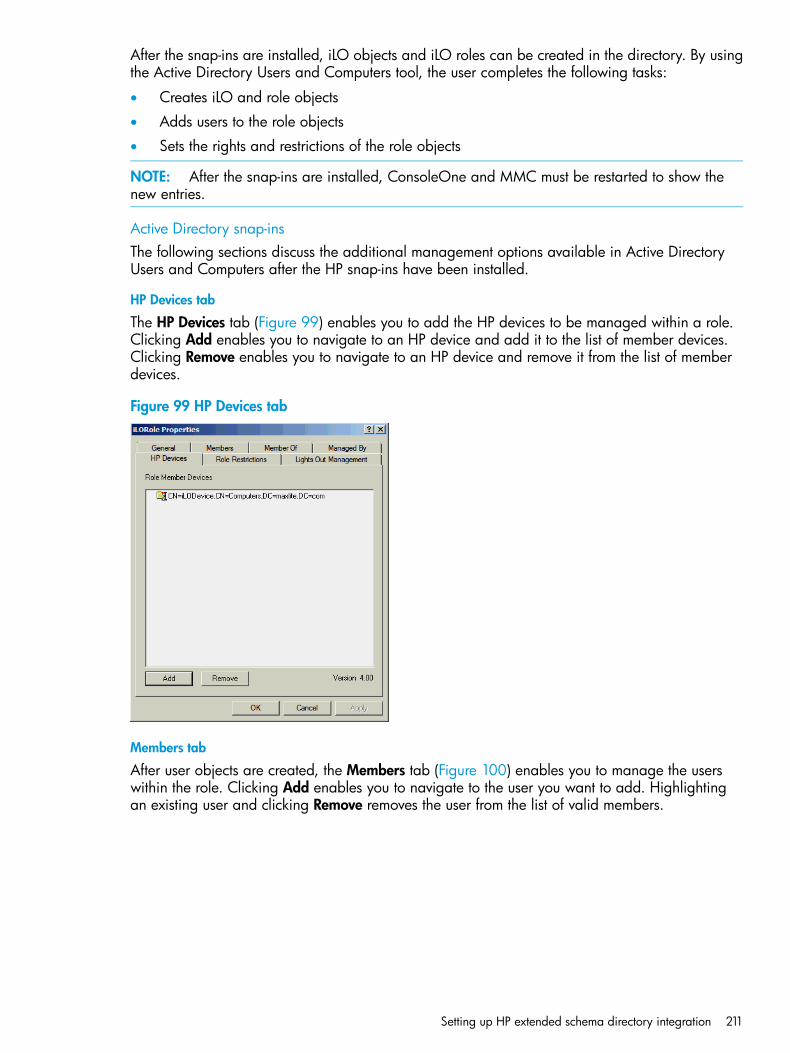
After the snap-ins are installed, iLO objects and iLO roles can be created in the directory. By usingthe Active Directory Users and Computers tool, the user completes the following tasks:
• Creates iLO and role objects
• Adds users to the role objects
• Sets the rights and restrictions of the role objects
NOTE: After the snap-ins are installed, ConsoleOne and MMC must be restarted to show thenew entries.
Active Directory snap-insThe following sections discuss the additional management options available in Active DirectoryUsers and Computers after the HP snap-ins have been installed.
HP Devices tab
The HP Devices tab (Figure 99) enables you to add the HP devices to be managed within a role.Clicking Add enables you to navigate to an HP device and add it to the list of member devices.Clicking Remove enables you to navigate to an HP device and remove it from the list of memberdevices.
Figure 99 HP Devices tab
Members tab
After user objects are created, the Members tab (Figure 100) enables you to manage the userswithin the role. Clicking Add enables you to navigate to the user you want to add. Highlightingan existing user and clicking Remove removes the user from the list of valid members.
Setting up HP extended schema directory integration 211
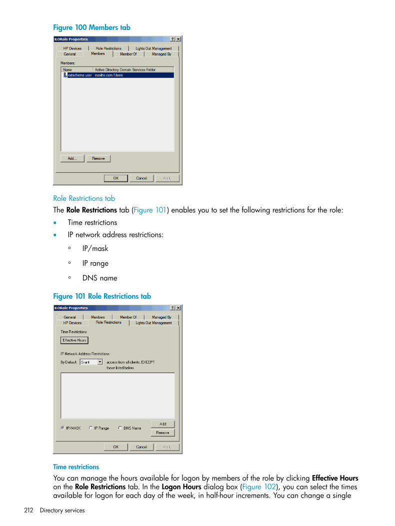
Figure 100 Members tab
Role Restrictions tabThe Role Restrictions tab (Figure 101) enables you to set the following restrictions for the role:
• Time restrictions
• IP network address restrictions:
IP/mask◦◦ IP range
◦ DNS name
Figure 101 Role Restrictions tab
Time restrictions
You can manage the hours available for logon by members of the role by clicking Effective Hourson the Role Restrictions tab. In the Logon Hours dialog box (Figure 102), you can select the timesavailable for logon for each day of the week, in half-hour increments. You can change a single
212 Directory services
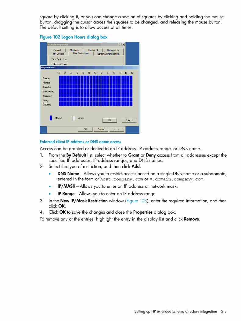
square by clicking it, or you can change a section of squares by clicking and holding the mousebutton, dragging the cursor across the squares to be changed, and releasing the mouse button.The default setting is to allow access at all times.
Figure 102 Logon Hours dialog box
Enforced client IP address or DNS name access
Access can be granted or denied to an IP address, IP address range, or DNS name.1. From the By Default list, select whether to Grant or Deny access from all addresses except the
specified IP addresses, IP address ranges, and DNS names.2. Select the type of restriction, and then click Add.
• DNS Name—Allows you to restrict access based on a single DNS name or a subdomain,entered in the form of host.company.com or *.domain.company.com.
• IP/MASK—Allows you to enter an IP address or network mask.
• IP Range—Allows you to enter an IP address range.3. In the New IP/Mask Restriction window (Figure 103), enter the required information, and then
click OK.4. Click OK to save the changes and close the Properties dialog box.To remove any of the entries, highlight the entry in the display list and click Remove.
Setting up HP extended schema directory integration 213
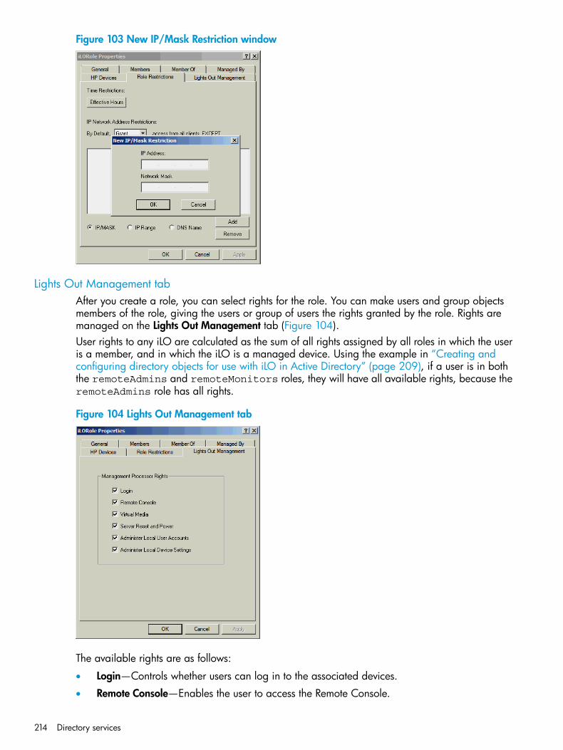
Figure 103 New IP/Mask Restriction window
Lights Out Management tabAfter you create a role, you can select rights for the role. You can make users and group objectsmembers of the role, giving the users or group of users the rights granted by the role. Rights aremanaged on the Lights Out Management tab (Figure 104).User rights to any iLO are calculated as the sum of all rights assigned by all roles in which the useris a member, and in which the iLO is a managed device. Using the example in “Creating andconfiguring directory objects for use with iLO in Active Directory” (page 209), if a user is in boththe remoteAdmins and remoteMonitors roles, they will have all available rights, because theremoteAdmins role has all rights.
Figure 104 Lights Out Management tab
The available rights are as follows:
• Login—Controls whether users can log in to the associated devices.
• Remote Console—Enables the user to access the Remote Console.
214 Directory services
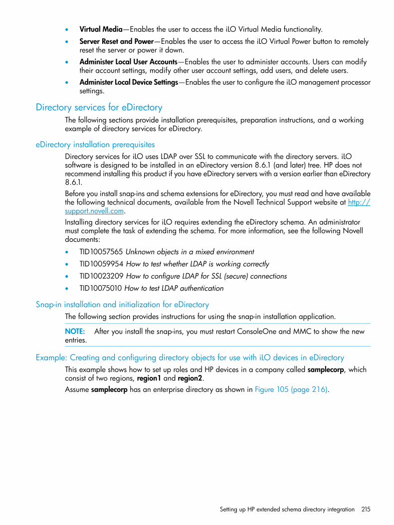
• Virtual Media—Enables the user to access the iLO Virtual Media functionality.
• Server Reset and Power—Enables the user to access the iLO Virtual Power button to remotelyreset the server or power it down.
• Administer Local User Accounts—Enables the user to administer accounts. Users can modifytheir account settings, modify other user account settings, add users, and delete users.
• Administer Local Device Settings—Enables the user to configure the iLO management processorsettings.
Directory services for eDirectoryThe following sections provide installation prerequisites, preparation instructions, and a workingexample of directory services for eDirectory.
eDirectory installation prerequisitesDirectory services for iLO uses LDAP over SSL to communicate with the directory servers. iLOsoftware is designed to be installed in an eDirectory version 8.6.1 (and later) tree. HP does notrecommend installing this product if you have eDirectory servers with a version earlier than eDirectory8.6.1.Before you install snap-ins and schema extensions for eDirectory, you must read and have availablethe following technical documents, available from the Novell Technical Support website at http://support.novell.com.Installing directory services for iLO requires extending the eDirectory schema. An administratormust complete the task of extending the schema. For more information, see the following Novelldocuments:
• TID10057565 Unknown objects in a mixed environment
• TID10059954 How to test whether LDAP is working correctly
• TID10023209 How to configure LDAP for SSL (secure) connections
• TID10075010 How to test LDAP authentication
Snap-in installation and initialization for eDirectoryThe following section provides instructions for using the snap-in installation application.
NOTE: After you install the snap-ins, you must restart ConsoleOne and MMC to show the newentries.
Example: Creating and configuring directory objects for use with iLO devices in eDirectoryThis example shows how to set up roles and HP devices in a company called samplecorp, whichconsist of two regions, region1 and region2.Assume samplecorp has an enterprise directory as shown in Figure 105 (page 216).
Setting up HP extended schema directory integration 215
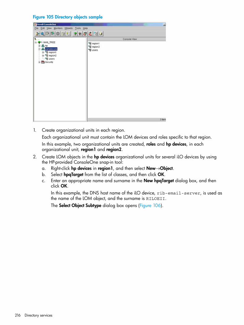
Figure 105 Directory objects sample
1. Create organizational units in each region.Each organizational unit must contain the LOM devices and roles specific to that region.In this example, two organizational units are created, roles and hp devices, in eachorganizational unit, region1 and region2.
2. Create LOM objects in the hp devices organizational units for several iLO devices by usingthe HP-provided ConsoleOne snap-in tool:a. Right-click hp devices in region1, and then select New→Object.b. Select hpqTarget from the list of classes, and then click OK.c. Enter an appropriate name and surname in the New hpqTarget dialog box, and then
click OK.In this example, the DNS host name of the iLO device, rib-email-server, is used asthe name of the LOM object, and the surname is RILOEII.The Select Object Subtype dialog box opens (Figure 106).
216 Directory services
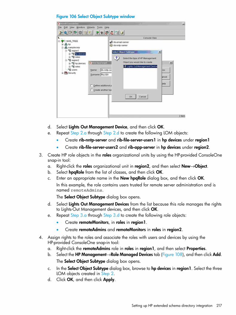
Figure 106 Select Object Subtype window
d. Select Lights Out Management Device, and then click OK.e. Repeat Step 2.a through Step 2.d to create the following LOM objects:
• Create rib-nntp-server and rib-file-server-users1 in hp devices under region1
• Create rib-file-server-users2 and rib-app-server in hp devices under region2.
3. Create HP role objects in the roles organizational units by using the HP-provided ConsoleOnesnap-in tool:a. Right-click the roles organizational unit in region2, and then select New→Object.b. Select hpqRole from the list of classes, and then click OK.c. Enter an appropriate name in the New hpqRole dialog box, and then click OK.
In this example, the role contains users trusted for remote server administration and isnamed remoteAdmins.The Select Object Subtype dialog box opens.
d. Select Lights Out Management Devices from the list because this role manages the rightsto Lights-Out Management devices, and then click OK.
e. Repeat Step 3.a through Step 3.d to create the following role objects:• Create remoteMonitors, in roles in region1.
• Create remoteAdmins and remoteMonitors in roles in region2.
4. Assign rights to the roles and associate the roles with users and devices by using theHP-provided ConsoleOne snap-in tool:a. Right-click the remoteAdmins role in roles in region1, and then select Properties.b. Select the HP Management→Role Managed Devices tab (Figure 108), and then click Add.
The Select Object Subtype dialog box opens.c. In the Select Object Subtype dialog box, browse to hp devices in region1. Select the three
LOM objects created in Step 2.d. Click OK, and then click Apply.
Setting up HP extended schema directory integration 217
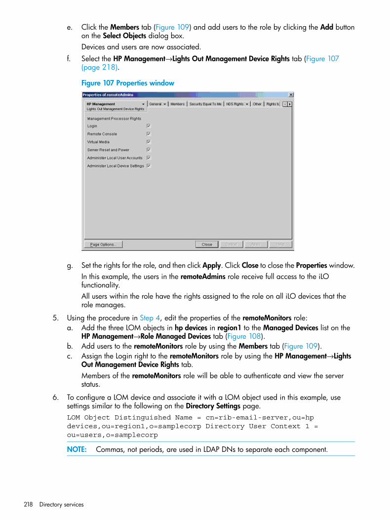
e. Click the Members tab (Figure 109) and add users to the role by clicking the Add buttonon the Select Objects dialog box.Devices and users are now associated.
f. Select the HP Management→Lights Out Management Device Rights tab (Figure 107(page 218).
Figure 107 Properties window
g. Set the rights for the role, and then click Apply. Click Close to close the Properties window.In this example, the users in the remoteAdmins role receive full access to the iLOfunctionality.All users within the role have the rights assigned to the role on all iLO devices that therole manages.
5. Using the procedure in Step 4, edit the properties of the remoteMonitors role:a. Add the three LOM objects in hp devices in region1 to the Managed Devices list on the
HP Management→Role Managed Devices tab (Figure 108).b. Add users to the remoteMonitors role by using the Members tab (Figure 109).c. Assign the Login right to the remoteMonitors role by using the HP Management→Lights
Out Management Device Rights tab.Members of the remoteMonitors role will be able to authenticate and view the serverstatus.
6. To configure a LOM device and associate it with a LOM object used in this example, usesettings similar to the following on the Directory Settings page.LOM Object Distinguished Name = cn=rib-email-server,ou=hpdevices,ou=region1,o=samplecorp Directory User Context 1 =ou=users,o=samplecorp
NOTE: Commas, not periods, are used in LDAP DNs to separate each component.
218 Directory services
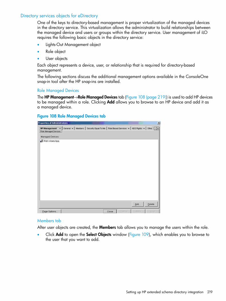
Directory services objects for eDirectoryOne of the keys to directory-based management is proper virtualization of the managed devicesin the directory service. This virtualization allows the administrator to build relationships betweenthe managed device and users or groups within the directory service. User management of iLOrequires the following basic objects in the directory service:
• Lights-Out Management object
• Role object
• User objectsEach object represents a device, user, or relationship that is required for directory-basedmanagement.The following sections discuss the additional management options available in the ConsoleOnesnap-in tool after the HP snap-ins are installed.
Role Managed DevicesThe HPManagement→Role Managed Devices tab (Figure 108 (page 219)) is used to add HP devicesto be managed within a role. Clicking Add allows you to browse to an HP device and add it asa managed device.
Figure 108 Role Managed Devices tab
Members tabAfter user objects are created, the Members tab allows you to manage the users within the role.
• Click Add to open the Select Objects window (Figure 109), which enables you to browse tothe user that you want to add.
Setting up HP extended schema directory integration 219
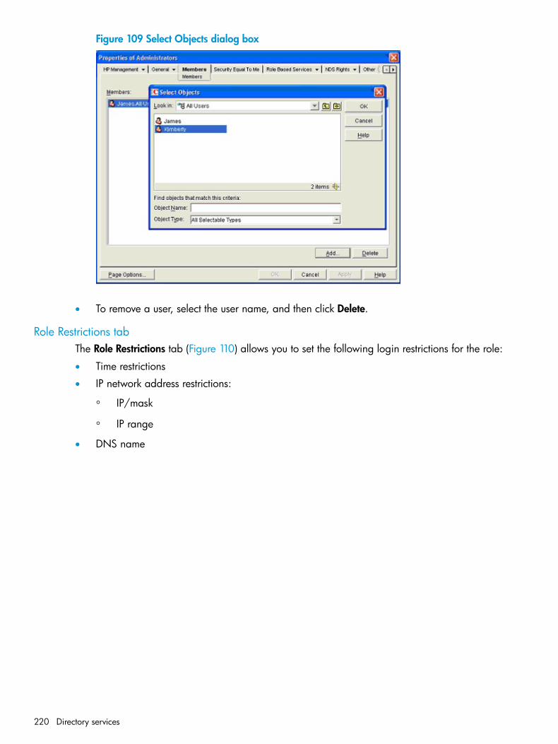
Figure 109 Select Objects dialog box
• To remove a user, select the user name, and then click Delete.
Role Restrictions tabThe Role Restrictions tab (Figure 110) allows you to set the following login restrictions for the role:
• Time restrictions
• IP network address restrictions:
IP/mask◦◦ IP range
• DNS name
220 Directory services
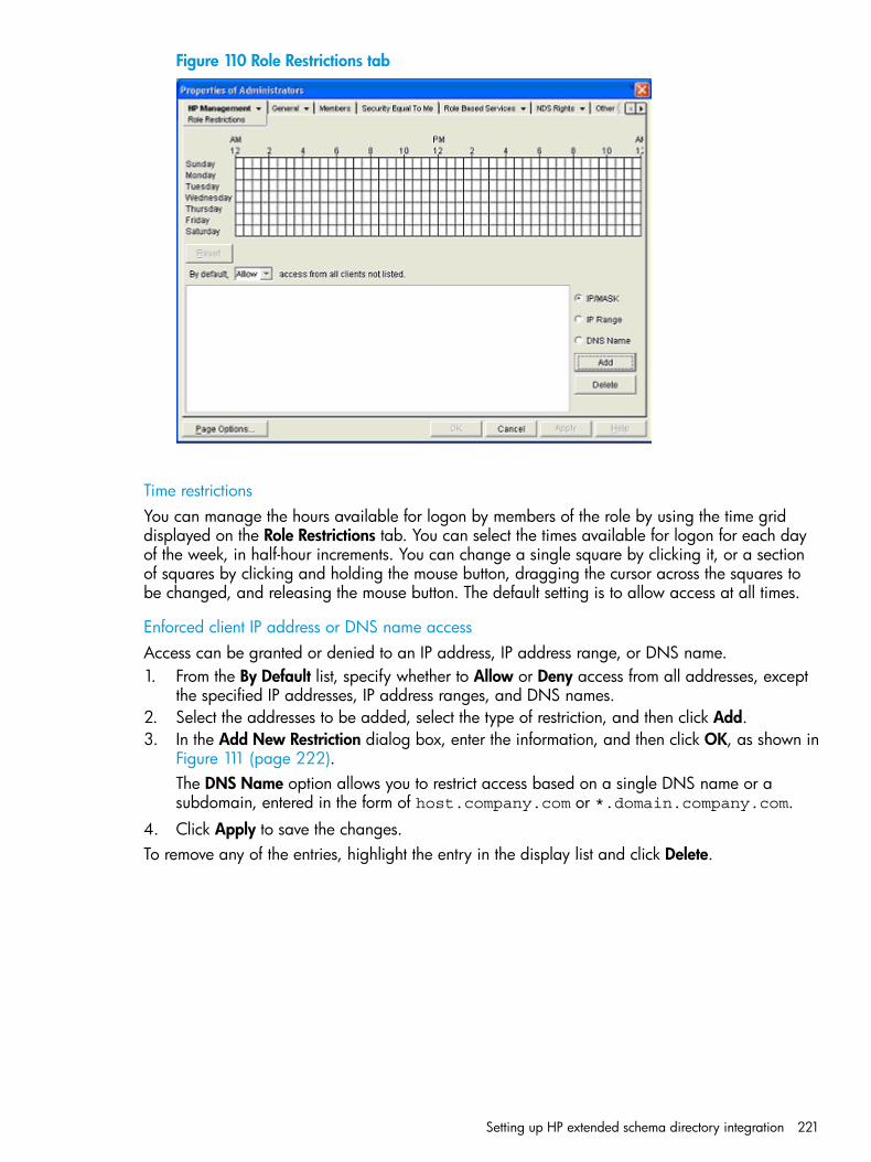
Figure 110 Role Restrictions tab
Time restrictionsYou can manage the hours available for logon by members of the role by using the time griddisplayed on the Role Restrictions tab. You can select the times available for logon for each dayof the week, in half-hour increments. You can change a single square by clicking it, or a sectionof squares by clicking and holding the mouse button, dragging the cursor across the squares tobe changed, and releasing the mouse button. The default setting is to allow access at all times.
Enforced client IP address or DNS name accessAccess can be granted or denied to an IP address, IP address range, or DNS name.1. From the By Default list, specify whether to Allow or Deny access from all addresses, except
the specified IP addresses, IP address ranges, and DNS names.2. Select the addresses to be added, select the type of restriction, and then click Add.3. In the Add New Restriction dialog box, enter the information, and then click OK, as shown in
Figure 111 (page 222).The DNS Name option allows you to restrict access based on a single DNS name or asubdomain, entered in the form of host.company.com or *.domain.company.com.
4. Click Apply to save the changes.To remove any of the entries, highlight the entry in the display list and click Delete.
Setting up HP extended schema directory integration 221
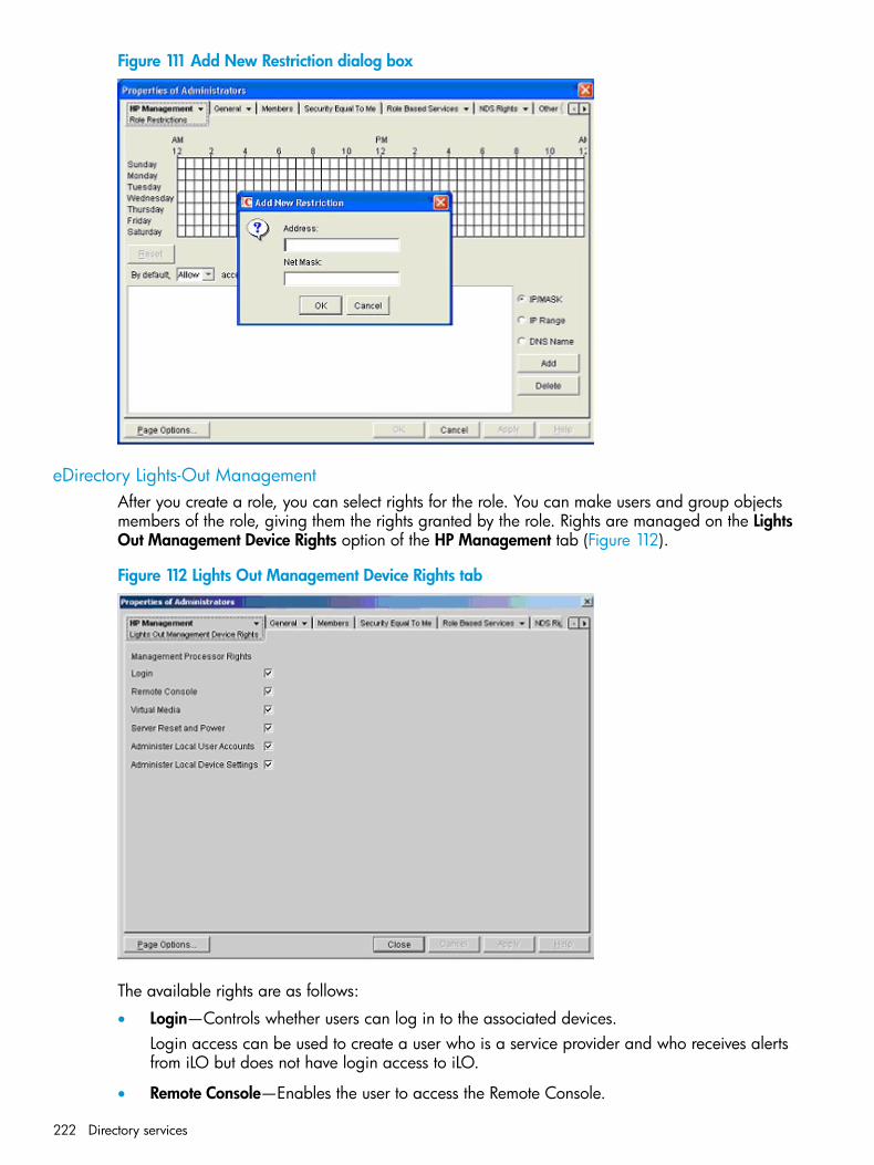
Figure 111 Add New Restriction dialog box
eDirectory Lights-Out ManagementAfter you create a role, you can select rights for the role. You can make users and group objectsmembers of the role, giving them the rights granted by the role. Rights are managed on the LightsOut Management Device Rights option of the HP Management tab (Figure 112).
Figure 112 Lights Out Management Device Rights tab
The available rights are as follows:
• Login—Controls whether users can log in to the associated devices.Login access can be used to create a user who is a service provider and who receives alertsfrom iLO but does not have login access to iLO.
• Remote Console—Enables the user to access the Remote Console.
222 Directory services
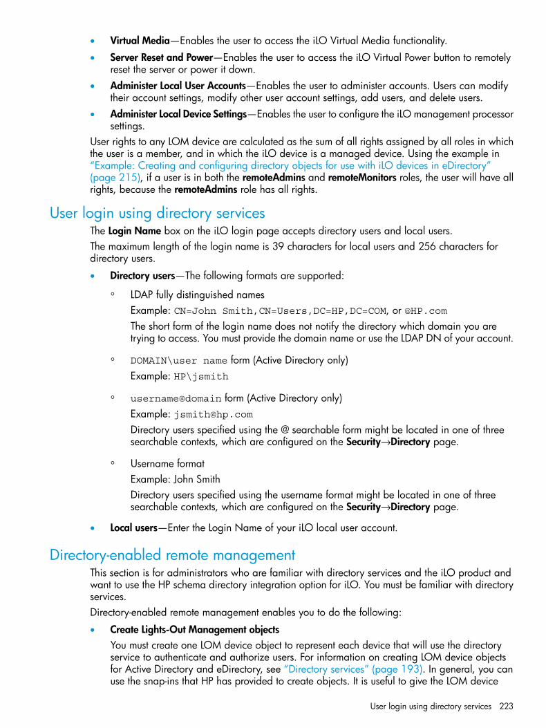
• Virtual Media—Enables the user to access the iLO Virtual Media functionality.
• Server Reset and Power—Enables the user to access the iLO Virtual Power button to remotelyreset the server or power it down.
• Administer Local User Accounts—Enables the user to administer accounts. Users can modifytheir account settings, modify other user account settings, add users, and delete users.
• Administer Local Device Settings—Enables the user to configure the iLO management processorsettings.
User rights to any LOM device are calculated as the sum of all rights assigned by all roles in whichthe user is a member, and in which the iLO device is a managed device. Using the example in“Example: Creating and configuring directory objects for use with iLO devices in eDirectory”(page 215), if a user is in both the remoteAdmins and remoteMonitors roles, the user will have allrights, because the remoteAdmins role has all rights.
User login using directory servicesThe Login Name box on the iLO login page accepts directory users and local users.The maximum length of the login name is 39 characters for local users and 256 characters fordirectory users.
• Directory users—The following formats are supported:
LDAP fully distinguished namesExample: CN=John Smith,CN=Users,DC=HP,DC=COM, or @HP.com
◦
The short form of the login name does not notify the directory which domain you aretrying to access. You must provide the domain name or use the LDAP DN of your account.
◦ DOMAIN\user name form (Active Directory only)Example: HP\jsmith
◦ username@domain form (Active Directory only)Example: [email protected] users specified using the @ searchable form might be located in one of threesearchable contexts, which are configured on the Security→Directory page.
◦ Username formatExample: John SmithDirectory users specified using the username format might be located in one of threesearchable contexts, which are configured on the Security→Directory page.
• Local users—Enter the Login Name of your iLO local user account.
Directory-enabled remote managementThis section is for administrators who are familiar with directory services and the iLO product andwant to use the HP schema directory integration option for iLO. You must be familiar with directoryservices.Directory-enabled remote management enables you to do the following:
• Create Lights-Out Management objectsYou must create one LOM device object to represent each device that will use the directoryservice to authenticate and authorize users. For information on creating LOM device objectsfor Active Directory and eDirectory, see “Directory services” (page 193). In general, you canuse the snap-ins that HP has provided to create objects. It is useful to give the LOM device
User login using directory services 223
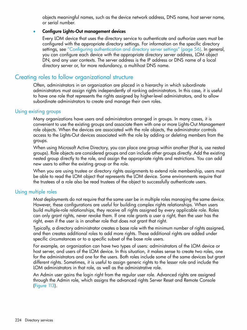
objects meaningful names, such as the device network address, DNS name, host server name,or serial number.
• Configure Lights-Out management devicesEvery LOM device that uses the directory service to authenticate and authorize users must beconfigured with the appropriate directory settings. For information on the specific directorysettings, see “Configuring authentication and directory server settings” (page 56). In general,you can configure each device with the appropriate directory server address, LOM objectDN, and any user contexts. The server address is the IP address or DNS name of a localdirectory server or, for more redundancy, a multihost DNS name.
Creating roles to follow organizational structureOften, administrators in an organization are placed in a hierarchy in which subordinateadministrators must assign rights independently of ranking administrators. In this case, it is usefulto have one role that represents the rights assigned by higher-level administrators, and to allowsubordinate administrators to create and manage their own roles.
Using existing groupsMany organizations have users and administrators arranged in groups. In many cases, it isconvenient to use the existing groups and associate them with one or more Lights-Out Managementrole objects. When the devices are associated with the role objects, the administrator controlsaccess to the Lights-Out devices associated with the role by adding or deleting members from thegroups.When using Microsoft Active Directory, you can place one group within another (that is, use nestedgroups). Role objects are considered groups and can include other groups directly. Add the existingnested group directly to the role, and assign the appropriate rights and restrictions. You can addnew users to either the existing group or the role.When you are using trustee or directory rights assignments to extend role membership, users mustbe able to read the LOM object that represents the LOM device. Some environments require thatthe trustees of a role also be read trustees of the object to successfully authenticate users.
Using multiple rolesMost deployments do not require that the same user be in multiple roles managing the same device.However, these configurations are useful for building complex rights relationships. When usersbuild multiple-role relationships, they receive all rights assigned by every applicable role. Rolescan only grant rights, never revoke them. If one role grants a user a right, then the user has theright, even if the user is in another role that does not grant that right.Typically, a directory administrator creates a base role with the minimum number of rights assigned,and then creates additional roles to add more rights. These additional rights are added underspecific circumstances or to a specific subset of the base role users.For example, an organization can have two types of users: administrators of the LOM device orhost server, and users of the LOM device. In this situation, it makes sense to create two roles, onefor the administrators and one for the users. Both roles include some of the same devices but grantdifferent rights. Sometimes, it is useful to assign generic rights to the lesser role and include theLOM administrators in that role, as well as the administrative role.An Admin user gains the login right from the regular user role. Advanced rights are assignedthrough the Admin role, which assigns the advanced rights Server Reset and Remote Console(Figure 113).
224 Directory services
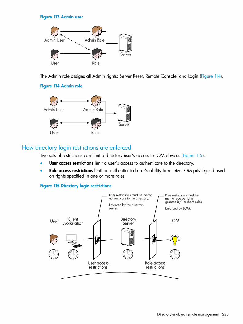
Figure 113 Admin user
Admin User
User
Admin Role
Role
Server
The Admin role assigns all Admin rights: Server Reset, Remote Console, and Login (Figure 114).
Figure 114 Admin role
Admin User
User
Admin Role
Role
Server
How directory login restrictions are enforcedTwo sets of restrictions can limit a directory user's access to LOM devices (Figure 115).
• User access restrictions limit a user's access to authenticate to the directory.
• Role access restrictions limit an authenticated user's ability to receive LOM privileges basedon rights specified in one or more roles.
Figure 115 Directory login restrictions
User LOMClientWorkstation
DirectoryServer
User restrictions must be met to authenticate to the directory.
Enforced by the directoryserver.
Role restrictions must bemet to receive rightsgranted by 1 or more roles.
Enforced by LOM.
Role accessrestrictions
User accessrestrictions
Directory-enabled remote management 225
Restricting rolesRestrictions allow administrators to limit the scope of a role. A role grants rights only to users whosatisfy the role restrictions. Using restricted roles results in users who have dynamic rights that canchange based on the time of day or network address of the client.
NOTE: When directories are enabled, access to a particular iLO is based on whether the userhas read access to a role object that contains the corresponding iLO object. This includes, but isnot limited to, the members listed in the role object. If the role is configured to allow inheritablepermissions to propagate from a parent, members of the parent that have read access privilegeswill also have access to iLO. To view the access control list, navigate to Active Directory Users andComputers, open the Properties page for the role object, and then click the Security tab. TheAdvanced View must be enabled in MMC in order to view the Security tab.
For instructions on how to create network and time restrictions for a role, see “Role Restrictionstab” (page 212) or “Role Restrictions tab” (page 220).
Role time restrictionsAdministrators can place time restrictions on LOM roles. Users are granted the rights specified forthe LOM devices listed in the role only if they are members of the role and meet the time restrictionsfor the role. LOM devices use local host time to enforce time restrictions. If the LOM device clockis not set, the role time restriction fails unless no time restrictions are specified for the role.Role-based time restrictions can be met only if the time is set on the LOM device. The time is normallyset when the host is booted. The time setting can be maintained by configuring SNTP, which allowsthe LOM device to compensate for leap years and minimize clock drift with respect to the host.Events, such as unexpected power loss or flashing LOM firmware, can cause the LOM device clockto not be set. Also, the host time must be correct for the LOM device to preserve time across firmwareflashes.
Role address restrictionsRole address restrictions are enforced by the LOM firmware, based on the client IP network address.When the address restrictions are met for a role, the rights granted by the role apply.Address restrictions can be difficult to manage if access is attempted across firewalls or throughnetwork proxies. Either of these mechanisms can change the apparent network address of theclient, causing the address restrictions to be enforced in an unexpected manner.
User restrictionsYou can restrict access using address or time restrictions.
User address restrictionsAdministrators can place network address restrictions on a directory user account, which areenforced by the directory server. For information about the enforcement of address restrictions onLDAP clients, such as a user logging in to a LOM device, see the documentation for the directoryservice.Network address restrictions placed on the user in the directory might not be enforced in theexpected manner if the directory user logs in through a proxy server. When a user logs in to aLOM device as a directory user, the LOM device attempts authentication to the directory as thatuser, which means that address restrictions placed on the user account apply when the user isaccessing the LOM device. However, because the user is proxied at the LOM device, the networkaddress of the authentication attempt is that of the LOM device, not that of the client workstation.
IP address range restrictions
IP address range restrictions enable the administrator to specify network addresses that are grantedor denied access. The address range is typically specified in a low-to-high range format. An address
226 Directory services
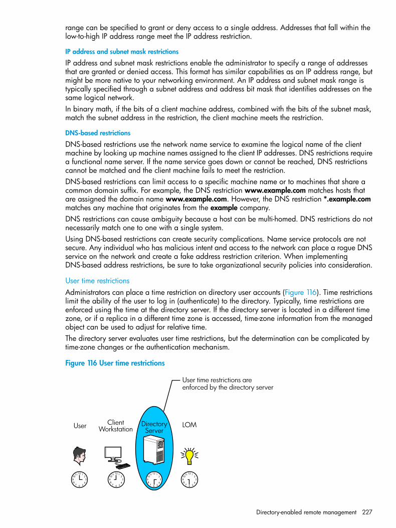
range can be specified to grant or deny access to a single address. Addresses that fall within thelow-to-high IP address range meet the IP address restriction.
IP address and subnet mask restrictions
IP address and subnet mask restrictions enable the administrator to specify a range of addressesthat are granted or denied access. This format has similar capabilities as an IP address range, butmight be more native to your networking environment. An IP address and subnet mask range istypically specified through a subnet address and address bit mask that identifies addresses on thesame logical network.In binary math, if the bits of a client machine address, combined with the bits of the subnet mask,match the subnet address in the restriction, the client machine meets the restriction.
DNS-based restrictions
DNS-based restrictions use the network name service to examine the logical name of the clientmachine by looking up machine names assigned to the client IP addresses. DNS restrictions requirea functional name server. If the name service goes down or cannot be reached, DNS restrictionscannot be matched and the client machine fails to meet the restriction.DNS-based restrictions can limit access to a specific machine name or to machines that share acommon domain suffix. For example, the DNS restriction www.example.com matches hosts thatare assigned the domain name www.example.com. However, the DNS restriction *.example.commatches any machine that originates from the example company.DNS restrictions can cause ambiguity because a host can be multi-homed. DNS restrictions do notnecessarily match one to one with a single system.Using DNS-based restrictions can create security complications. Name service protocols are notsecure. Any individual who has malicious intent and access to the network can place a rogue DNSservice on the network and create a fake address restriction criterion. When implementingDNS-based address restrictions, be sure to take organizational security policies into consideration.
User time restrictionsAdministrators can place a time restriction on directory user accounts (Figure 116). Time restrictionslimit the ability of the user to log in (authenticate) to the directory. Typically, time restrictions areenforced using the time at the directory server. If the directory server is located in a different timezone, or if a replica in a different time zone is accessed, time-zone information from the managedobject can be used to adjust for relative time.The directory server evaluates user time restrictions, but the determination can be complicated bytime-zone changes or the authentication mechanism.
Figure 116 User time restrictions
User LOMClientWorkstation
DirectoryServer
User time restrictions areenforced by the directory server
Directory-enabled remote management 227
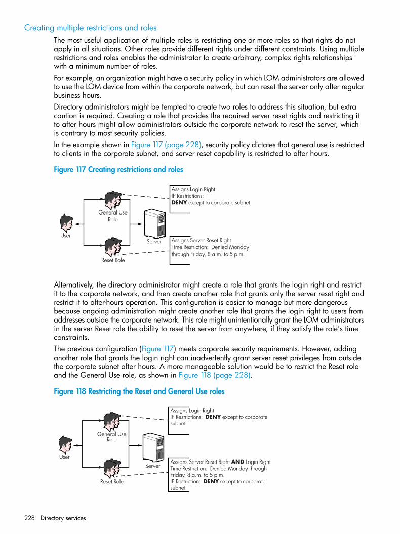
Creating multiple restrictions and rolesThe most useful application of multiple roles is restricting one or more roles so that rights do notapply in all situations. Other roles provide different rights under different constraints. Using multiplerestrictions and roles enables the administrator to create arbitrary, complex rights relationshipswith a minimum number of roles.For example, an organization might have a security policy in which LOM administrators are allowedto use the LOM device from within the corporate network, but can reset the server only after regularbusiness hours.Directory administrators might be tempted to create two roles to address this situation, but extracaution is required. Creating a role that provides the required server reset rights and restricting itto after hours might allow administrators outside the corporate network to reset the server, whichis contrary to most security policies.In the example shown in Figure 117 (page 228), security policy dictates that general use is restrictedto clients in the corporate subnet, and server reset capability is restricted to after hours.
Figure 117 Creating restrictions and roles
User
General UseRole
Reset Role
Assigns Login RightIP Restrictions:DENY except to corporate subnet
Server Assigns Server Reset RightTime Restriction: Denied Mondaythrough Friday, 8 a.m. to 5 p.m.
Alternatively, the directory administrator might create a role that grants the login right and restrictit to the corporate network, and then create another role that grants only the server reset right andrestrict it to after-hours operation. This configuration is easier to manage but more dangerousbecause ongoing administration might create another role that grants the login right to users fromaddresses outside the corporate network. This role might unintentionally grant the LOM administratorsin the server Reset role the ability to reset the server from anywhere, if they satisfy the role's timeconstraints.The previous configuration (Figure 117) meets corporate security requirements. However, addinganother role that grants the login right can inadvertently grant server reset privileges from outsidethe corporate subnet after hours. A more manageable solution would be to restrict the Reset roleand the General Use role, as shown in Figure 118 (page 228).
Figure 118 Restricting the Reset and General Use roles
User
General UseRole
Reset Role
Assigns Login RightIP Restrictions: DENY except to corporate subnet
ServerAssigns Server Reset Right AND Login RightTime Restriction: Denied Monday throughFriday, 8 a.m. to 5 p.m.IP Restriction: DENY except to corporatesubnet
228 Directory services
Using bulk import toolsAdding and configuring large numbers of LOM objects is time consuming. HP provides severalutilities to assist with these tasks.
• HP Lights-Out Migration utilityThe HP Lights-Out Migration utility imports and configures multiple LOM devices. It includesa GUI that provides a step-by-step approach to implementing or upgrading large numbers ofmanagement processors. HP recommends using this GUI method when upgrading severalmanagement processors. For more information, see “Using HP Directories Support for ProLiantManagement Processors” (page 230).
• HP SIM utilitiesThe HP SIM utilities enable you to perform the following tasks:
◦ Manage multiple LOM devices.
◦ Discover the LOM devices as management processors by using HPQLOCFG to send aRIBCL XML script file to a group of LOM devices. The LOM devices perform the actionsdesignated by the RIBCL file and send a response to the HPQLOCFG log file. For moreinformation, see the HP iLO 4 Scripting and Command Line Guide.
• Traditional import utilitiesAdministrators familiar with tools such as LDIFDE or the NDS Import/Export Wizard can usethese utilities to import or create many LOM device objects in the directory. Administratorsmust still configure the devices manually, as described earlier, but can do so at any time.Programmatic or scripting interfaces can also be used to create the LOM device objects inthe same way as users or other objects. For information about attributes and attribute dataformats when you are creating LOM objects, see “Directory services schema” (page 273).
HP Directories Support for ProLiant Management Processors utilityYou can download this utility from http://www.hp.com/support/ilo4.The HP Directories Support for ProLiant Management Processors utility (HPLOMIG.exe) is forcustomers who installed management processors and want to simplify the migration of theseprocessors to management by directories. The utility automates some of the migration steps necessaryfor the management processors to support directory services. The utility can do the following:
• Discover management processors on the network.
• Upgrade the management processor firmware.
• Name the management processors to identify them in the directory.
• Create objects in the directory that correspond to each management processor, and associatethem with a role.
• Configure the management processors to enable them to communicate with the directory.
CompatibilityThe HP Directories Support for ProLiant Management Processors utility operates on MicrosoftWindows and requires the Microsoft .NET Framework. The utility supports the following operatingsystems:
• Windows Server 2003 32-bit, 64-bit
• Windows Server 2008 32-bit, 64-bit
• Windows Server 2008 R2
• Windows Vista
HP Directories Support for ProLiant Management Processors utility 229
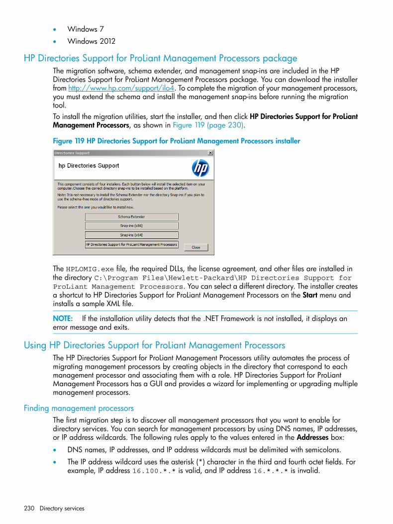
• Windows 7
• Windows 2012
HP Directories Support for ProLiant Management Processors packageThe migration software, schema extender, and management snap-ins are included in the HPDirectories Support for ProLiant Management Processors package. You can download the installerfrom http://www.hp.com/support/ilo4. To complete the migration of your management processors,you must extend the schema and install the management snap-ins before running the migrationtool.To install the migration utilities, start the installer, and then click HP Directories Support for ProLiantManagement Processors, as shown in Figure 119 (page 230).
Figure 119 HP Directories Support for ProLiant Management Processors installer
The HPLOMIG.exe file, the required DLLs, the license agreement, and other files are installed inthe directory C:\Program Files\Hewlett-Packard\HP Directories Support forProLiant Management Processors. You can select a different directory. The installer createsa shortcut to HP Directories Support for ProLiant Management Processors on the Start menu andinstalls a sample XML file.
NOTE: If the installation utility detects that the .NET Framework is not installed, it displays anerror message and exits.
Using HP Directories Support for ProLiant Management ProcessorsThe HP Directories Support for ProLiant Management Processors utility automates the process ofmigrating management processors by creating objects in the directory that correspond to eachmanagement processor and associating them with a role. HP Directories Support for ProLiantManagement Processors has a GUI and provides a wizard for implementing or upgrading multiplemanagement processors.
Finding management processorsThe first migration step is to discover all management processors that you want to enable fordirectory services. You can search for management processors by using DNS names, IP addresses,or IP address wildcards. The following rules apply to the values entered in the Addresses box:
• DNS names, IP addresses, and IP address wildcards must be delimited with semicolons.
• The IP address wildcard uses the asterisk (*) character in the third and fourth octet fields. Forexample, IP address 16.100.*.* is valid, and IP address 16.*.*.* is invalid.
230 Directory services
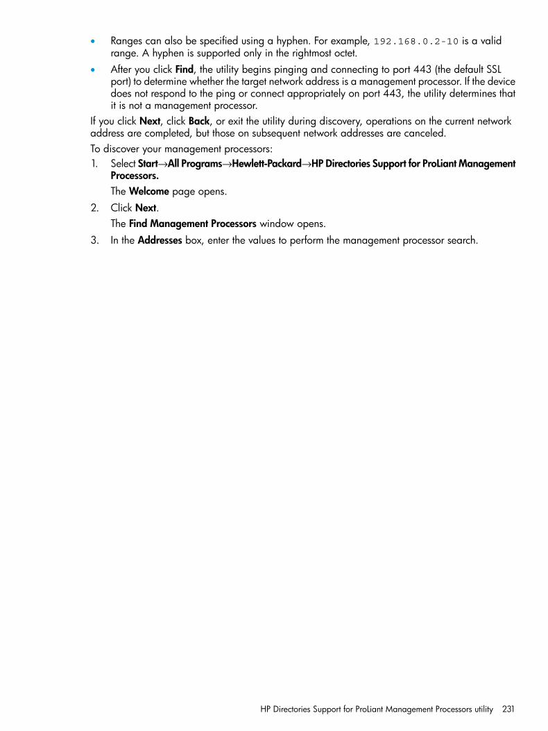
• Ranges can also be specified using a hyphen. For example, 192.168.0.2-10 is a validrange. A hyphen is supported only in the rightmost octet.
• After you click Find, the utility begins pinging and connecting to port 443 (the default SSLport) to determine whether the target network address is a management processor. If the devicedoes not respond to the ping or connect appropriately on port 443, the utility determines thatit is not a management processor.
If you click Next, click Back, or exit the utility during discovery, operations on the current networkaddress are completed, but those on subsequent network addresses are canceled.To discover your management processors:1. Select Start→All Programs→Hewlett-Packard→HP Directories Support for ProLiant Management
Processors.The Welcome page opens.
2. Click Next.The Find Management Processors window opens.
3. In the Addresses box, enter the values to perform the management processor search.
HP Directories Support for ProLiant Management Processors utility 231
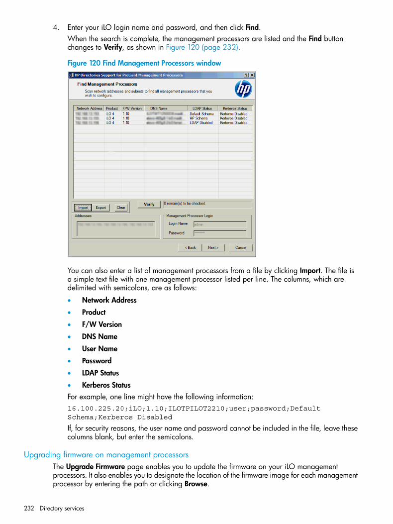
4. Enter your iLO login name and password, and then click Find.When the search is complete, the management processors are listed and the Find buttonchanges to Verify, as shown in Figure 120 (page 232).
Figure 120 Find Management Processors window
You can also enter a list of management processors from a file by clicking Import. The file isa simple text file with one management processor listed per line. The columns, which aredelimited with semicolons, are as follows:
• Network Address
• Product
• F/W Version
• DNS Name
• User Name
• Password
• LDAP Status
• Kerberos StatusFor example, one line might have the following information:16.100.225.20;iLO;1.10;ILOTPILOT2210;user;password;DefaultSchema;Kerberos Disabled
If, for security reasons, the user name and password cannot be included in the file, leave thesecolumns blank, but enter the semicolons.
Upgrading firmware on management processorsThe Upgrade Firmware page enables you to update the firmware on your iLO managementprocessors. It also enables you to designate the location of the firmware image for each managementprocessor by entering the path or clicking Browse.
232 Directory services
NOTE: Binary images of the firmware for the management processors must be accessible fromthe system that is running the migration utility. These binary images can be downloaded fromhttp://www.hp.com/support/ilo4.
The upgrade process might take a long time, depending on the number of management processorsselected. The firmware upgrade of a single management processor can take as long as 5 minutesto complete. If an upgrade fails, a message is displayed in the Results column, and the utilitycontinues to upgrade the other discovered management processors.
IMPORTANT: HP recommends that you test the upgrade process and verify the results in a testenvironment before running the utility on a production network. An incomplete transfer of thefirmware image to a management processor might result in having to locally reprogram themanagement processor.
To upgrade the firmware on your management processors:1. Navigate to the Upgrade Firmware on Management Processors window, as shown in
Figure 121 (page 233).
Figure 121 Upgrade Firmware on Management Processors window
2. Select the management processors to upgrade.3. For each discovered management processor type, enter the correct pathname to the firmware
image or browse to the image.4. Click Upgrade Firmware.
The selected management processors are upgraded. Although this utility enables you toupgrade hundreds of management processors, only 25 management processors are upgradedsimultaneously. Network activity is considerable during this process.
5. After the upgrade is complete, click Next.During the firmware upgrade process, all buttons are deactivated to prevent navigation. You canstill close the application by clicking the X at the top right of the page. If the GUI is closed during
HP Directories Support for ProLiant Management Processors utility 233
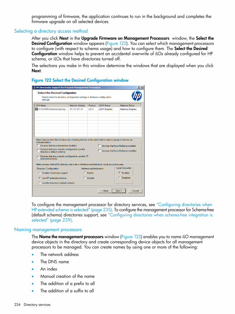
programming of firmware, the application continues to run in the background and completes thefirmware upgrade on all selected devices.
Selecting a directory access methodAfter you click Next in the Upgrade Firmware on Management Processors window, the Select theDesired Configuration window appears (Figure 122). You can select which management processorsto configure (with respect to schema usage) and how to configure them. The Select the DesiredConfiguration window helps to prevent an accidental overwrite of iLOs already configured for HPschema, or iLOs that have directories turned off.The selections you make in this window determine the windows that are displayed when you clickNext.
Figure 122 Select the Desired Configuration window
To configure the management processor for directory services, see “Configuring directories whenHP extended schema is selected” (page 235). To configure the management processor for Schema-free(default schema) directories support, see “Configuring directories when schema-free integration isselected” (page 239).
Naming management processorsThe Name the management processors window (Figure 123) enables you to name iLO managementdevice objects in the directory and create corresponding device objects for all managementprocessors to be managed. You can create names by using one or more of the following:
• The network address
• The DNS name
• An index
• Manual creation of the name
• The addition of a prefix to all
• The addition of a suffix to all
234 Directory services
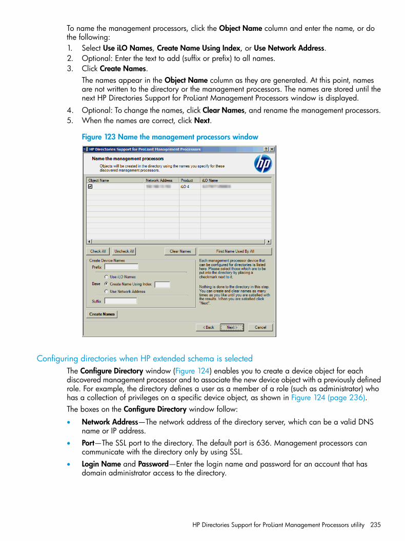
To name the management processors, click the Object Name column and enter the name, or dothe following:1. Select Use iLO Names, Create Name Using Index, or Use Network Address.2. Optional: Enter the text to add (suffix or prefix) to all names.3. Click Create Names.
The names appear in the Object Name column as they are generated. At this point, namesare not written to the directory or the management processors. The names are stored until thenext HP Directories Support for ProLiant Management Processors window is displayed.
4. Optional: To change the names, click Clear Names, and rename the management processors.5. When the names are correct, click Next.
Figure 123 Name the management processors window
Configuring directories when HP extended schema is selectedThe Configure Directory window (Figure 124) enables you to create a device object for eachdiscovered management processor and to associate the new device object with a previously definedrole. For example, the directory defines a user as a member of a role (such as administrator) whohas a collection of privileges on a specific device object, as shown in Figure 124 (page 236).The boxes on the Configure Directory window follow:
• Network Address—The network address of the directory server, which can be a valid DNSname or IP address.
• Port—The SSL port to the directory. The default port is 636. Management processors cancommunicate with the directory only by using SSL.
• Login Name and Password—Enter the login name and password for an account that hasdomain administrator access to the directory.
HP Directories Support for ProLiant Management Processors utility 235
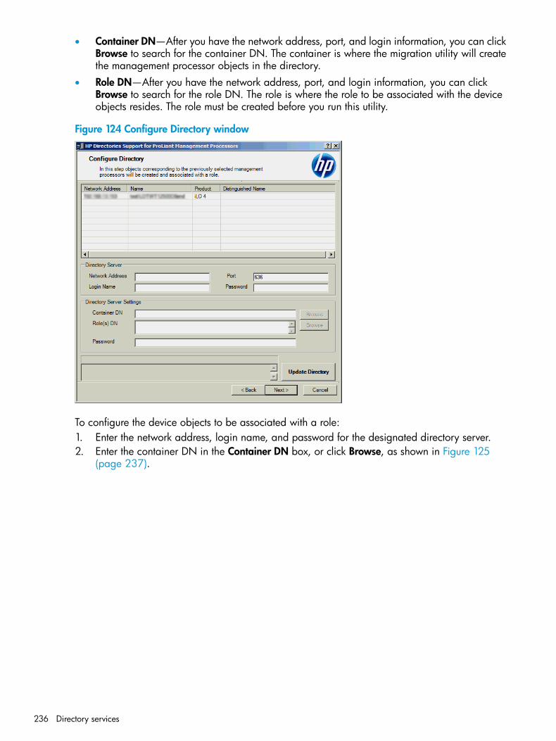
• Container DN—After you have the network address, port, and login information, you can clickBrowse to search for the container DN. The container is where the migration utility will createthe management processor objects in the directory.
• Role DN—After you have the network address, port, and login information, you can clickBrowse to search for the role DN. The role is where the role to be associated with the deviceobjects resides. The role must be created before you run this utility.
Figure 124 Configure Directory window
To configure the device objects to be associated with a role:1. Enter the network address, login name, and password for the designated directory server.2. Enter the container DN in the Container DN box, or click Browse, as shown in Figure 125
(page 237).
236 Directory services
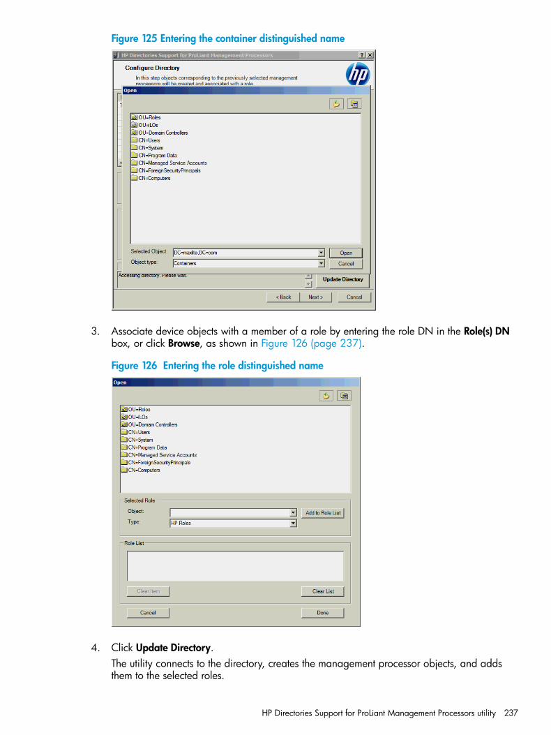
Figure 125 Entering the container distinguished name
3. Associate device objects with a member of a role by entering the role DN in the Role(s) DNbox, or click Browse, as shown in Figure 126 (page 237).
Figure 126 Entering the role distinguished name
4. Click Update Directory.The utility connects to the directory, creates the management processor objects, and addsthem to the selected roles.
HP Directories Support for ProLiant Management Processors utility 237
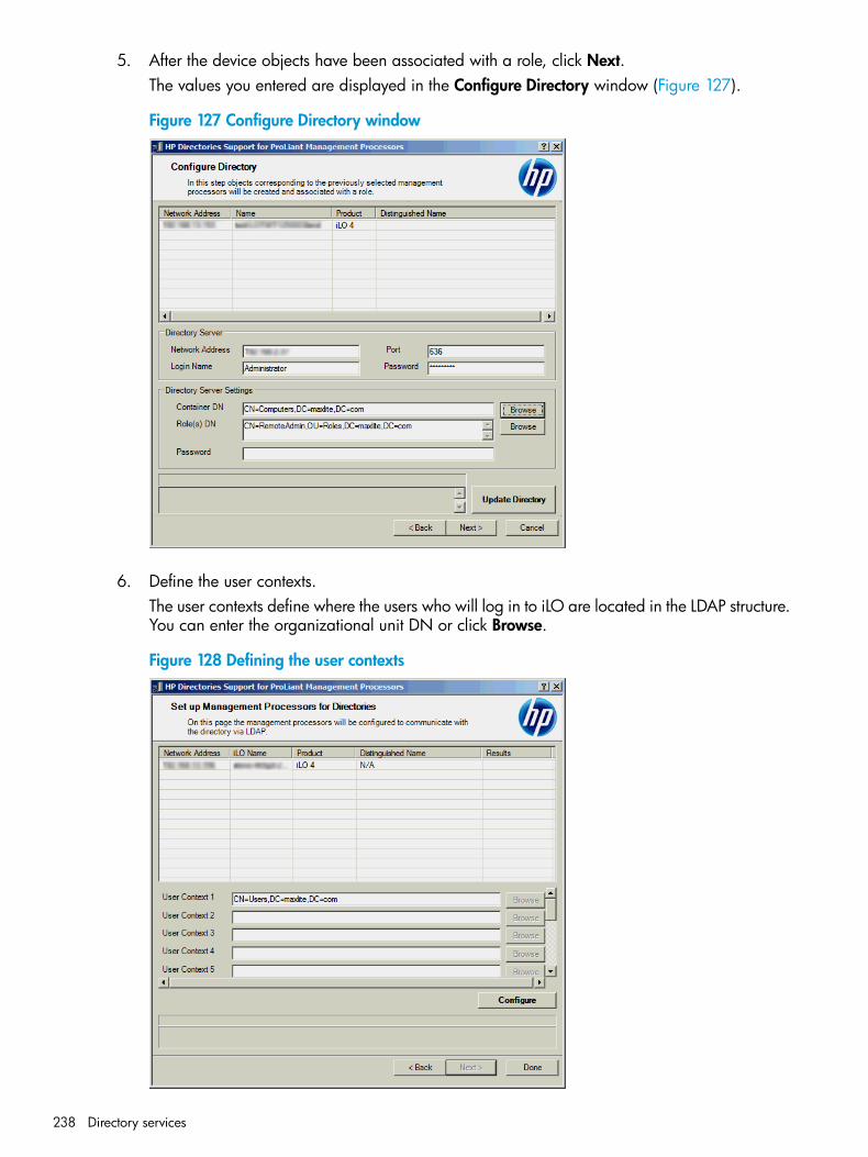
5. After the device objects have been associated with a role, click Next.The values you entered are displayed in the Configure Directory window (Figure 127).
Figure 127 Configure Directory window
6. Define the user contexts.The user contexts define where the users who will log in to iLO are located in the LDAP structure.You can enter the organizational unit DN or click Browse.
Figure 128 Defining the user contexts
238 Directory services
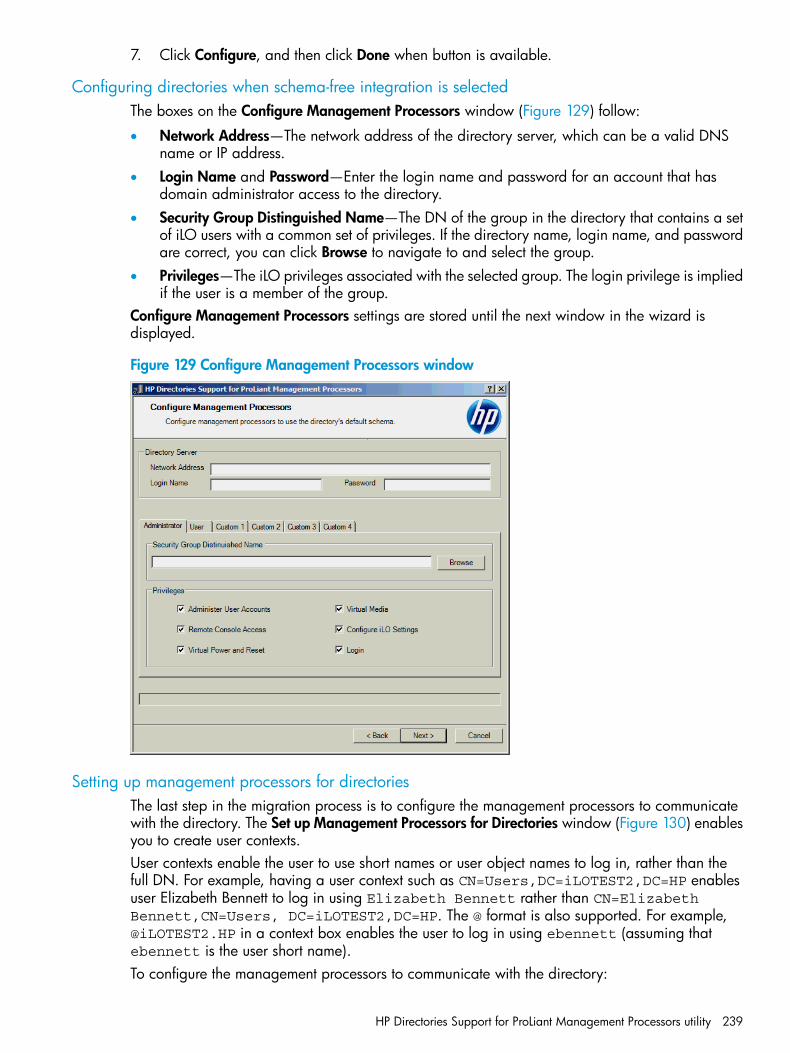
7. Click Configure, and then click Done when button is available.
Configuring directories when schema-free integration is selectedThe boxes on the Configure Management Processors window (Figure 129) follow:
• Network Address—The network address of the directory server, which can be a valid DNSname or IP address.
• Login Name and Password—Enter the login name and password for an account that hasdomain administrator access to the directory.
• Security Group Distinguished Name—The DN of the group in the directory that contains a setof iLO users with a common set of privileges. If the directory name, login name, and passwordare correct, you can click Browse to navigate to and select the group.
• Privileges—The iLO privileges associated with the selected group. The login privilege is impliedif the user is a member of the group.
Configure Management Processors settings are stored until the next window in the wizard isdisplayed.
Figure 129 Configure Management Processors window
Setting up management processors for directoriesThe last step in the migration process is to configure the management processors to communicatewith the directory. The Set up Management Processors for Directories window (Figure 130) enablesyou to create user contexts.User contexts enable the user to use short names or user object names to log in, rather than thefull DN. For example, having a user context such as CN=Users,DC=iLOTEST2,DC=HP enablesuser Elizabeth Bennett to log in using Elizabeth Bennett rather than CN=ElizabethBennett,CN=Users, DC=iLOTEST2,DC=HP. The @ format is also supported. For example,@iLOTEST2.HP in a context box enables the user to log in using ebennett (assuming thatebennett is the user short name).To configure the management processors to communicate with the directory:
HP Directories Support for ProLiant Management Processors utility 239
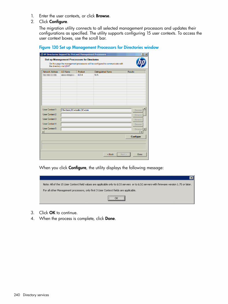
1. Enter the user contexts, or click Browse.2. Click Configure.
The migration utility connects to all selected management processors and updates theirconfigurations as specified. The utility supports configuring 15 user contexts. To access theuser context boxes, use the scroll bar.
Figure 130 Set up Management Processors for Directories window
When you click Configure, the utility displays the following message:
3. Click OK to continue.4. When the process is complete, click Done.
240 Directory services
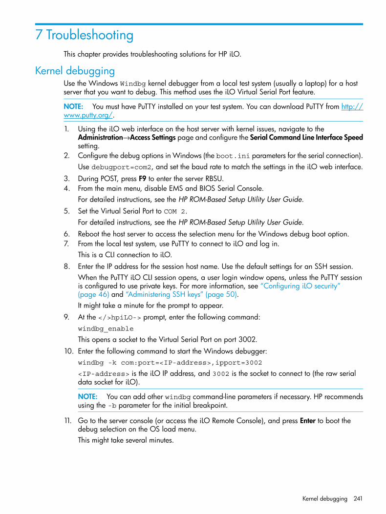
7 TroubleshootingThis chapter provides troubleshooting solutions for HP iLO.
Kernel debuggingUse the Windows Windbg kernel debugger from a local test system (usually a laptop) for a hostserver that you want to debug. This method uses the iLO Virtual Serial Port feature.
NOTE: You must have PuTTY installed on your test system. You can download PuTTY from http://www.putty.org/.
1. Using the iLO web interface on the host server with kernel issues, navigate to theAdministration→Access Settings page and configure the Serial Command Line Interface Speedsetting.
2. Configure the debug options in Windows (the boot.ini parameters for the serial connection).Use debugport=com2, and set the baud rate to match the settings in the iLO web interface.
3. During POST, press F9 to enter the server RBSU.4. From the main menu, disable EMS and BIOS Serial Console.
For detailed instructions, see the HP ROM-Based Setup Utility User Guide.5. Set the Virtual Serial Port to COM 2.
For detailed instructions, see the HP ROM-Based Setup Utility User Guide.6. Reboot the host server to access the selection menu for the Windows debug boot option.7. From the local test system, use PuTTY to connect to iLO and log in.
This is a CLI connection to iLO.8. Enter the IP address for the session host name. Use the default settings for an SSH session.
When the PuTTY iLO CLI session opens, a user login window opens, unless the PuTTY sessionis configured to use private keys. For more information, see “Configuring iLO security”(page 46) and “Administering SSH keys” (page 50).It might take a minute for the prompt to appear.
9. At the </>hpiLO-> prompt, enter the following command:windbg_enable
This opens a socket to the Virtual Serial Port on port 3002.10. Enter the following command to start the Windows debugger:
windbg -k com:port=<IP-address>,ipport=3002
<IP-address> is the iLO IP address, and 3002 is the socket to connect to (the raw serialdata socket for iLO).
NOTE: You can add other windbg command-line parameters if necessary. HP recommendsusing the -b parameter for the initial breakpoint.
11. Go to the server console (or access the iLO Remote Console), and press Enter to boot thedebug selection on the OS load menu.This might take several minutes.
Kernel debugging 241
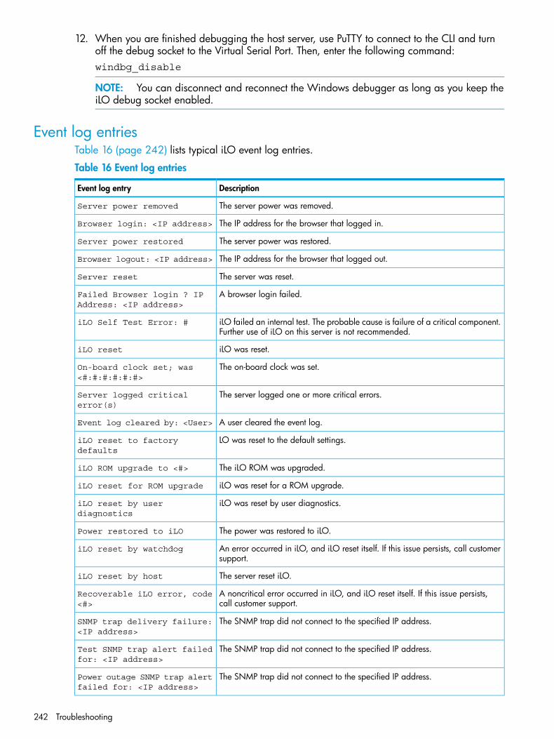
12. When you are finished debugging the host server, use PuTTY to connect to the CLI and turnoff the debug socket to the Virtual Serial Port. Then, enter the following command:windbg_disable
NOTE: You can disconnect and reconnect the Windows debugger as long as you keep theiLO debug socket enabled.
Event log entriesTable 16 (page 242) lists typical iLO event log entries.
Table 16 Event log entries
DescriptionEvent log entry
The server power was removed.Server power removed
The IP address for the browser that logged in.Browser login: <IP address>
The server power was restored.Server power restored
The IP address for the browser that logged out.Browser logout: <IP address>
The server was reset.Server reset
A browser login failed.Failed Browser login ? IPAddress: <IP address>
iLO failed an internal test. The probable cause is failure of a critical component.Further use of iLO on this server is not recommended.
iLO Self Test Error: #
iLO was reset.iLO reset
The on-board clock was set.On-board clock set; was<#:#:#:#:#:#>
The server logged one or more critical errors.Server logged criticalerror(s)
A user cleared the event log.Event log cleared by: <User>
LO was reset to the default settings.iLO reset to factorydefaults
The iLO ROM was upgraded.iLO ROM upgrade to <#>
iLO was reset for a ROM upgrade.iLO reset for ROM upgrade
iLO was reset by user diagnostics.iLO reset by userdiagnostics
The power was restored to iLO.Power restored to iLO
An error occurred in iLO, and iLO reset itself. If this issue persists, call customersupport.
iLO reset by watchdog
The server reset iLO.iLO reset by host
A noncritical error occurred in iLO, and iLO reset itself. If this issue persists,call customer support.
Recoverable iLO error, code<#>
The SNMP trap did not connect to the specified IP address.SNMP trap delivery failure:<IP address>
The SNMP trap did not connect to the specified IP address.Test SNMP trap alert failedfor: <IP address>
The SNMP trap did not connect to the specified IP address.Power outage SNMP trap alertfailed for: <IP address>
242 Troubleshooting
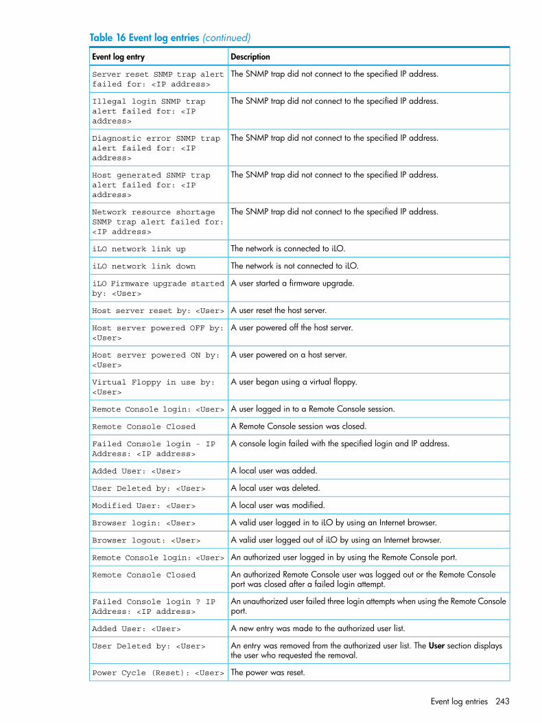
Table 16 Event log entries (continued)
DescriptionEvent log entry
The SNMP trap did not connect to the specified IP address.Server reset SNMP trap alertfailed for: <IP address>
The SNMP trap did not connect to the specified IP address.Illegal login SNMP trapalert failed for: <IPaddress>
The SNMP trap did not connect to the specified IP address.Diagnostic error SNMP trapalert failed for: <IPaddress>
The SNMP trap did not connect to the specified IP address.Host generated SNMP trapalert failed for: <IPaddress>
The SNMP trap did not connect to the specified IP address.Network resource shortageSNMP trap alert failed for:<IP address>
The network is connected to iLO.iLO network link up
The network is not connected to iLO.iLO network link down
A user started a firmware upgrade.iLO Firmware upgrade startedby: <User>
A user reset the host server.Host server reset by: <User>
A user powered off the host server.Host server powered OFF by:<User>
A user powered on a host server.Host server powered ON by:<User>
A user began using a virtual floppy.Virtual Floppy in use by:<User>
A user logged in to a Remote Console session.Remote Console login: <User>
A Remote Console session was closed.Remote Console Closed
A console login failed with the specified login and IP address.Failed Console login - IPAddress: <IP address>
A local user was added.Added User: <User>
A local user was deleted.User Deleted by: <User>
A local user was modified.Modified User: <User>
A valid user logged in to iLO by using an Internet browser.Browser login: <User>
A valid user logged out of iLO by using an Internet browser.Browser logout: <User>
An authorized user logged in by using the Remote Console port.Remote Console login: <User>
An authorized Remote Console user was logged out or the Remote Consoleport was closed after a failed login attempt.
Remote Console Closed
An unauthorized user failed three login attempts when using the Remote Consoleport.
Failed Console login ? IPAddress: <IP address>
A new entry was made to the authorized user list.Added User: <User>
An entry was removed from the authorized user list. The User section displaysthe user who requested the removal.
User Deleted by: <User>
The power was reset.Power Cycle (Reset): <User>
Event log entries 243
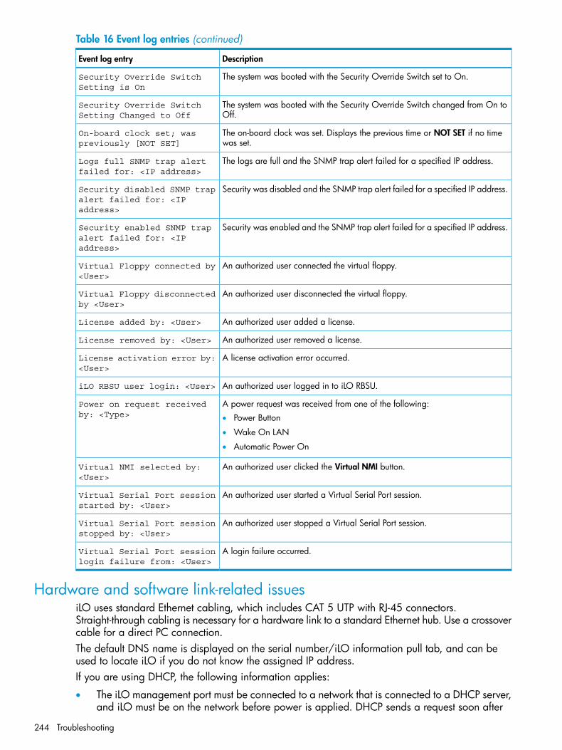
Table 16 Event log entries (continued)
DescriptionEvent log entry
The system was booted with the Security Override Switch set to On.Security Override SwitchSetting is On
The system was booted with the Security Override Switch changed from On toOff.
Security Override SwitchSetting Changed to Off
The on-board clock was set. Displays the previous time or NOT SET if no timewas set.
On-board clock set; waspreviously [NOT SET]
The logs are full and the SNMP trap alert failed for a specified IP address.Logs full SNMP trap alertfailed for: <IP address>
Security was disabled and the SNMP trap alert failed for a specified IP address.Security disabled SNMP trapalert failed for: <IPaddress>
Security was enabled and the SNMP trap alert failed for a specified IP address.Security enabled SNMP trapalert failed for: <IPaddress>
An authorized user connected the virtual floppy.Virtual Floppy connected by<User>
An authorized user disconnected the virtual floppy.Virtual Floppy disconnectedby <User>
An authorized user added a license.License added by: <User>
An authorized user removed a license.License removed by: <User>
A license activation error occurred.License activation error by:<User>
An authorized user logged in to iLO RBSU.iLO RBSU user login: <User>
A power request was received from one of the following:Power on request receivedby: <Type> • Power Button
• Wake On LAN
• Automatic Power On
An authorized user clicked the Virtual NMI button.Virtual NMI selected by:<User>
An authorized user started a Virtual Serial Port session.Virtual Serial Port sessionstarted by: <User>
An authorized user stopped a Virtual Serial Port session.Virtual Serial Port sessionstopped by: <User>
A login failure occurred.Virtual Serial Port sessionlogin failure from: <User>
Hardware and software link-related issuesiLO uses standard Ethernet cabling, which includes CAT 5 UTP with RJ-45 connectors.Straight-through cabling is necessary for a hardware link to a standard Ethernet hub. Use a crossovercable for a direct PC connection.The default DNS name is displayed on the serial number/iLO information pull tab, and can beused to locate iLO if you do not know the assigned IP address.If you are using DHCP, the following information applies:
• The iLO management port must be connected to a network that is connected to a DHCP server,and iLO must be on the network before power is applied. DHCP sends a request soon after
244 Troubleshooting
power is applied. If the DHCP request is not answered when iLO first boots, it will reissue therequest at 90-second intervals.
• The DHCP server must be configured to provide DNS and WINS name resolution.
• In the iLO RBSU, you can press F1 on the Network Autoconfiguration page for advancedoptions for viewing the status of iLO DHCP requests.
If you are using a static IP address, the following information applies:
• If you have a direct PC connection then you must use a static IP address because no DHCPserver is present on the link.
• You can configure iLO to work with a static IP address by using iLO RBSU or the iLO webinterface. For more information, see “Setting up iLO by using iLO RBSU” (page 18) and “Settingup iLO by using the iLO web interface” (page 21).
Login issuesUse the following information when attempting to resolve login issues:
• Try using the default account information, which is located on the serial number/iLO informationpull tab.
• If you forget your password, it can be reset by an administrator who has the Administer UserAccounts privilege.
• If an administrator forgets the administrator account password, the administrator must use theSecurity Override Switch or use HPONCFG to establish an administrator account and password.For instructions, see the HP iLO 4 Scripting and Command Line Guide.
• Check for standard issues, such as the following:
Does the password comply with password restrictions? For example, does the passwordcontain case-sensitive characters?
◦
◦ Is an unsupported browser being used?
Login name and password not acceptedSolution: Verify that your login information is configured correctly. Have a user with the AdministerUser Accounts privilege log in and change your password. If you still cannot connect, have theuser log in again and delete and re-add your user account. For instructions, see “Administeringusers” (page 33).
NOTE: The RBSU can also be used to configure user accounts. For instructions, see “Setting upiLO user accounts by using iLO RBSU” (page 20).
Directory user premature logoutSolution: To recover from a premature session timeout, log back in and continue using iLO. If thedirectory server is unavailable, you must use a local account.Network errors can cause iLO to conclude that a directory connection is no longer valid. If iLOcannot detect the directory, it ends the directory connection. Any attempt to continue using theterminated connection redirects the browser to the login page.A premature session timeout can occur during an active session if:
• The network connection is terminated.
• The directory server is shut down.
Login issues 245
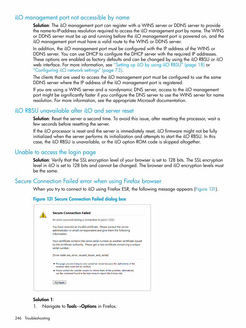
iLO management port not accessible by nameSolution: The iLO management port can register with a WINS server or DDNS server to providethe name-to-IP-address resolution required to access the iLO management port by name. The WINSor DDNS server must be up and running before the iLO management port is powered on, and theiLO management port must have a valid route to the WINS or DDNS server.In addition, the iLO management port must be configured with the IP address of the WINS orDDNS server. You can use DHCP to configure the DHCP server with the required IP addresses.These options are enabled as factory defaults and can be changed by using the iLO RBSU or iLOweb interface. For more information, see “Setting up iLO by using iLO RBSU” (page 18) or“Configuring iLO network settings” (page 73).The clients that are used to access the iLO management port must be configured to use the sameDDNS server where the IP address of the iLO management port is registered.If you are using a WINS server and a nondynamic DNS server, access to the iLO managementport might be significantly faster if you configure the DNS server to use the WINS server for nameresolution. For more information, see the appropriate Microsoft documentation.
iLO RBSU unavailable after iLO and server resetSolution: Reset the server a second time. To avoid this issue, after resetting the processor, wait afew seconds before resetting the server.If the iLO processor is reset and the server is immediately reset, iLO firmware might not be fullyinitialized when the server performs its initialization and attempts to start the iLO RBSU. In thiscase, the iLO RBSU is unavailable, or the iLO option ROM code is skipped altogether.
Unable to access the login pageSolution: Verify that the SSL encryption level of your browser is set to 128 bits. The SSL encryptionlevel in iLO is set to 128 bits and cannot be changed. The browser and iLO encryption levels mustbe the same.
Secure Connection Failed error when using Firefox browserWhen you try to connect to iLO using Firefox ESR, the following message appears (Figure 131).
Figure 131 Secure Connection Failed dialog box
Solution 1:1. Navigate to Tools→Options in Firefox.
246 Troubleshooting
2. Click Advanced.3. Click the Encryption tab.4. Click View Certificates.
Click the Servers tab, and then delete any certificates related to iLO.5. Click the Others tab, and then delete any certificates related to iLO.6. Click OK.7. Start Firefox and connect to iLO.
NOTE: The steps in Solution 1 are based on Firefox ESR 17. The procedure to use might varydepending on the installed version of Firefox.
Solution 2:1. Close the Firefox application.2. Navigate to the Firefox AppData folder, and then delete all of the *.db files in all of the
Firefox directories.The AppData folder is typically in the following location: C:\\Users\<user name>\AppData\Local\Mozilla\Firefox\
Unable to return to login page after an iLO flash or resetSolution: Clear the browser cache and restart the browser.
Unable to access Virtual Media or graphical Remote ConsoleSolution: You enable the iLO Virtual Media and graphical Remote Console features by installingan optional iLO license. If a license is not installed, a message informs you that these features arenot available without a license.For details on purchasing licenses, and for a list of licensed features, see the following website:http://www.hp.com/go/ilo/licensing.
Unable to connect to iLO after changing network settingsSolution: Verify that both sides of the connection (the NIC and the switch) have the same settingsfor transceiver speed autoselect, speed, and duplex. For example, if one side is autoselecting theconnection, the other side must use the same setting. For information about configuring the iLOnetwork settings, see “Configuring iLO network settings” (page 73).
Unable to connect to iLO processor through NICSolution: If you cannot connect to the iLO processor through the NIC, try the following solutions:
• Confirm that the green LED indicator (link status) on the iLO RJ-45 connector is on. This conditionindicates a good connection between the PCI NIC and the network hub.
• Look for intermittent flashes of the green LED indicator, which indicates normal network traffic.
• Run the iLO RBSU to confirm that the NIC is enabled, and verify the assigned IP address andsubnet mask.
• Run the iLO RBSU, and use the Advanced option on the Network Autoconfiguration page toview the status of DHCP requests.
• Ping the IP address of the NIC from a separate network workstation.
• Attempt to connect with a browser by entering the IP address of the NIC as the URL. You cansee the iLO home page from this address.
• Reset iLO.
Login issues 247
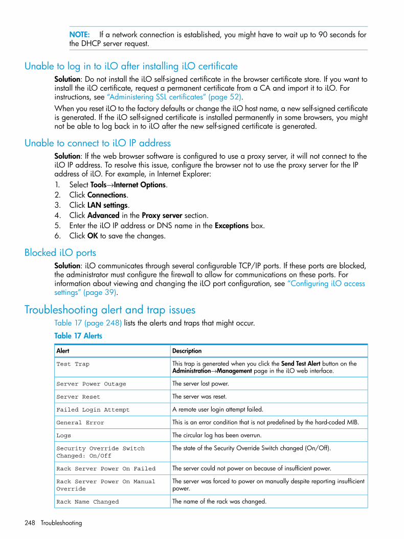
NOTE: If a network connection is established, you might have to wait up to 90 seconds forthe DHCP server request.
Unable to log in to iLO after installing iLO certificateSolution: Do not install the iLO self-signed certificate in the browser certificate store. If you want toinstall the iLO certificate, request a permanent certificate from a CA and import it to iLO. Forinstructions, see “Administering SSL certificates” (page 52).When you reset iLO to the factory defaults or change the iLO host name, a new self-signed certificateis generated. If the iLO self-signed certificate is installed permanently in some browsers, you mightnot be able to log back in to iLO after the new self-signed certificate is generated.
Unable to connect to iLO IP addressSolution: If the web browser software is configured to use a proxy server, it will not connect to theiLO IP address. To resolve this issue, configure the browser not to use the proxy server for the IPaddress of iLO. For example, in Internet Explorer:1. Select Tools→Internet Options.2. Click Connections.3. Click LAN settings.4. Click Advanced in the Proxy server section.5. Enter the iLO IP address or DNS name in the Exceptions box.6. Click OK to save the changes.
Blocked iLO portsSolution: iLO communicates through several configurable TCP/IP ports. If these ports are blocked,the administrator must configure the firewall to allow for communications on these ports. Forinformation about viewing and changing the iLO port configuration, see “Configuring iLO accesssettings” (page 39).
Troubleshooting alert and trap issuesTable 17 (page 248) lists the alerts and traps that might occur.
Table 17 Alerts
DescriptionAlert
This trap is generated when you click the Send Test Alert button on theAdministration→Management page in the iLO web interface.
Test Trap
The server lost power.Server Power Outage
The server was reset.Server Reset
A remote user login attempt failed.Failed Login Attempt
This is an error condition that is not predefined by the hard-coded MIB.General Error
The circular log has been overrun.Logs
The state of the Security Override Switch changed (On/Off).Security Override SwitchChanged: On/Off
The server could not power on because of insufficient power.Rack Server Power On Failed
The server was forced to power on manually despite reporting insufficientpower.
Rack Server Power On ManualOverride
The name of the rack was changed.Rack Name Changed
248 Troubleshooting
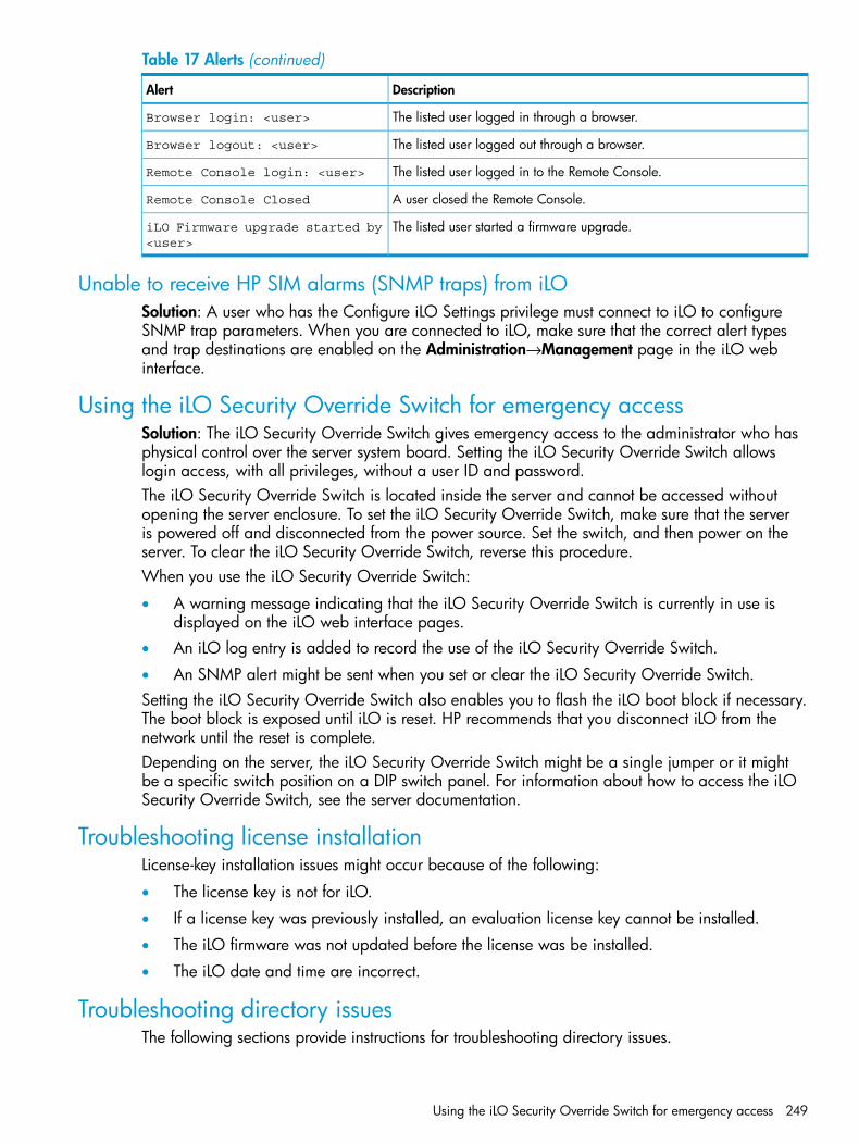
Table 17 Alerts (continued)
DescriptionAlert
The listed user logged in through a browser.Browser login: <user>
The listed user logged out through a browser.Browser logout: <user>
The listed user logged in to the Remote Console.Remote Console login: <user>
A user closed the Remote Console.Remote Console Closed
The listed user started a firmware upgrade.iLO Firmware upgrade started by<user>
Unable to receive HP SIM alarms (SNMP traps) from iLOSolution: A user who has the Configure iLO Settings privilege must connect to iLO to configureSNMP trap parameters. When you are connected to iLO, make sure that the correct alert typesand trap destinations are enabled on the Administration→Management page in the iLO webinterface.
Using the iLO Security Override Switch for emergency accessSolution: The iLO Security Override Switch gives emergency access to the administrator who hasphysical control over the server system board. Setting the iLO Security Override Switch allowslogin access, with all privileges, without a user ID and password.The iLO Security Override Switch is located inside the server and cannot be accessed withoutopening the server enclosure. To set the iLO Security Override Switch, make sure that the serveris powered off and disconnected from the power source. Set the switch, and then power on theserver. To clear the iLO Security Override Switch, reverse this procedure.When you use the iLO Security Override Switch:
• A warning message indicating that the iLO Security Override Switch is currently in use isdisplayed on the iLO web interface pages.
• An iLO log entry is added to record the use of the iLO Security Override Switch.
• An SNMP alert might be sent when you set or clear the iLO Security Override Switch.Setting the iLO Security Override Switch also enables you to flash the iLO boot block if necessary.The boot block is exposed until iLO is reset. HP recommends that you disconnect iLO from thenetwork until the reset is complete.Depending on the server, the iLO Security Override Switch might be a single jumper or it mightbe a specific switch position on a DIP switch panel. For information about how to access the iLOSecurity Override Switch, see the server documentation.
Troubleshooting license installationLicense-key installation issues might occur because of the following:
• The license key is not for iLO.
• If a license key was previously installed, an evaluation license key cannot be installed.
• The iLO firmware was not updated before the license was be installed.
• The iLO date and time are incorrect.
Troubleshooting directory issuesThe following sections provide instructions for troubleshooting directory issues.
Using the iLO Security Override Switch for emergency access 249
User contexts do not appear to workSolution: Check with your network administrator. The full DN of your user object must be in thedirectory. Your login name appears after the first CN=. The remainder of the DN must appear inone of the user context boxes. User contexts are not case sensitive, and any other characters,including spaces, are part of the user context. For information about entering directory user contexts,see “Configuring directory settings” (page 55).
Directory user does not log out after directory timeout has expiredSolution: If you set the iLO Idle Connection Timeout to Infinite, the Remote Console periodicallypings the firmware to verify that the connection exists. When the ping occurs, the iLO firmwarequeries the directory for user permissions. This periodic query keeps the directory connection active,preventing a timeout and logging the user.
Problems generating keytab by using ktpass.exe
Solution: If you use ktpass.exe to generate a keytab, you must specify a principal name byusing the -princ argument.Principal names are case sensitive and must be entered as follows:HTTP/[email protected]
• The first part is uppercase (HTTP).
• The middle part is lowercase (myilo.somedomain.net).
• The last part is uppercase (@SOMEDOMAIN.NET).If you do not format the command exactly as shown, it will not work.Here is an example of the full ktpass.exe command:ktpass +rndPass -ptype KRB5_NT_SRV_HST -mapuser [email protected] HTTP/[email protected] -out myilo.keytab
Troubleshooting Remote Console issuesThe following sections discuss troubleshooting Remote Console issues.
IMPORTANT: Pop-up blocking applications, which prevent the automatic opening of new windows,prevent the Remote Console from running. Disable any pop-up blocking programs before you startthe Remote Console.
Java IRC applet displays red X when Firefox is used to run Java IRC on Linux clientSolution: Firefox browsers must be configured to accept cookies. For instructions on configuringFirefox, see the Firefox documentation.
Unable to navigate single cursor of Remote Console to corners of Remote Consolewindow
In some cases, you might not be able to navigate the mouse cursor to the corners of the RemoteConsole window.Solution: Right-click and drag the mouse cursor outside the Remote Console window, and thendrag it back inside.
Remote Console text window not updated correctlyWhen you are using the Remote Console to display text windows that scroll at a high rate of speed,the text window might not be updated correctly. This error is caused by video updates occurring
250 Troubleshooting
faster than the iLO firmware can detect and display them. Typically, only the upper left corner ofthe text window is updated while the rest of the text window remains static.Solution: After the scrolling is complete, click Refresh to update the text window.
Mouse or keyboard not working in .NET IRC or Java IRCSolution 1: When you open the .NET IRC or Java IRC and notice that the mouse or keyboard isnot working, perform the following steps:1. Close the .NET IRC or Java IRC.2. Navigate to the Power Management→Power Settings page.3. Clear the Enable persistent mouse and keyboard check box, and then click Apply.4. Start the .NET IRC or Java IRC again.Solution 2 (.NET IRC only): Some monitors do not support DirectDraw. For example, some USBVGA device drivers might disable DirectDraw on all monitors for Windows Vista and Windows7 clients.The .NET IRC requires DirectDraw support.Solution 2 (Java IRC only):1. Shut down and exit your browser.2. Open the Java Control Panel.3. Navigate to the Java Runtime Environment Settings dialog box.4. Add the following runtime parameter:
-Dsun.java2d.noddraw=true
5. Click OK and close the Java Runtime Environment Settings window.6. Click Apply, and then click OK to close the Java Control Panel.
NOTE: Viewing your changes before you click Apply might reset the Runtime Parametersdialog box, causing your edits to be lost.
.NET IRC sends characters continuously after switching windowsSolution: If you have a key pressed during a .NET IRC session, and you inadvertently switchwindows, the key can remain pressed in the .NET IRC session, causing the character to repeatcontinuously. To stop the character from repeating, click the .NET IRC session screen to bring it tothe front of your desktop.
Java IRC does not display correct floppy and USB-key deviceThis issue occurs only with the Firefox browser.Solution:1. Make sure that Red Hat Enterprise Linux 5 or later is installed on the local client system.2. Install the latest version of Java and configure it to connect through the Firefox browser.3. Log in to the iLO web interface by using Firefox.4. Insert a USB key or floppy disk on the local client system.5. Verify that you can access the USB key or floppy disk.6. Open a Java IRC session.7. Select Virtual Drives→Floppy/USB-Key, and then select Virtual Image.
The Choose Disk Image File dialog box opens (Figure 132).
Troubleshooting Remote Console issues 251
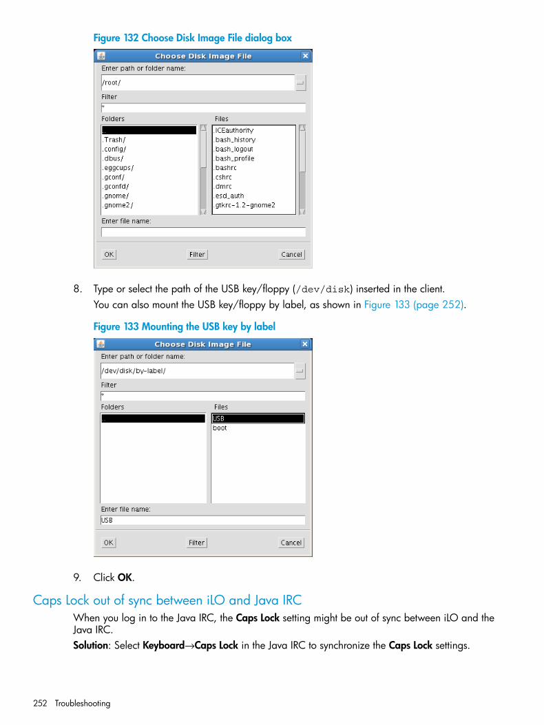
Figure 132 Choose Disk Image File dialog box
8. Type or select the path of the USB key/floppy (/dev/disk) inserted in the client.You can also mount the USB key/floppy by label, as shown in Figure 133 (page 252).
Figure 133 Mounting the USB key by label
9. Click OK.
Caps Lock out of sync between iLO and Java IRCWhen you log in to the Java IRC, the Caps Lock setting might be out of sync between iLO and theJava IRC.Solution: Select Keyboard→Caps Lock in the Java IRC to synchronize the Caps Lock settings.
252 Troubleshooting
Num Lock out of sync between iLO and Shared Remote ConsoleWhen you log in to a Shared Remote Console session, the Num Lock setting might be out of syncbetween iLO and some of the Remote Console sessions.Solution: Select Keyboard→Num Lock in the Remote Console to synchronize the Num Lock settings.
Keystrokes repeat unintentionally during Remote Console sessionWhen you are using the .NET IRC or Java IRC, a keystroke might repeat unintentionally during aRemote Console session.Solution 1: Identify and fix problems that might cause network latency.Solution 2: Adjust the following settings on the remote machine:
• Increase the typematic delay—This setting controls the delay before a character repeats whenyou press and hold a key on the keyboard.
• Decrease the typematic rate—This setting controls the rate at which a character repeats whenyou press and hold a key on the keyboard.
NOTE: The exact name of the setting varies depending on the OS you are using. For moreinformation about changing the typematic delay and rate, see your OS documentation.
Session leader does not receive connection request when .NET IRC is in replay modeSolution: When a Remote Console session leader plays captured video data, the .NET IRC doesnot display the Deny or Accept message when another user attempts to access or share the .NETIRC. Instead, the new .NET IRC session waits and eventually times out. If you require access to the.NET IRC, and your request times out, contact the other user or use the Remote Console Acquirefeature to take control of the IRC. For instructions, see “Acquiring the Remote Console” (page 150).
Keyboard LED does not work correctlyThe client keyboard LED does not reflect the true state of the keyboard lock keys. The Caps Lock,Num Lock, and Scroll Lock keys are fully functional when you are using the keyboard options inthe Remote Console.
Inactive .NET IRCThe iLO .NET IRC might become inactive or disconnect during periods of high activity. .NET IRCactivity slows before becoming inactive. Symptoms of an affected .NET IRC include the following:
• The .NET IRC display is not updated.
• Keyboard and mouse activity is not recorded.
• Shared Remote Console requests do not register.Although you can replay a captured file on an inactive .NET IRC, the active state of the .NET IRCis not restored.This issue might occur when multiple users are logged in to iLO, a Virtual Media session is connectedand is performing a continuous copy operation, or a .NET IRC session is open. The Virtual Mediacontinuous copy operation takes priority and, consequently, the .NET IRC loses synchronization.Eventually, the Virtual Media connection resets multiple times and causes the USB media drive forthe OS to lose synchronization with the Virtual Media client.Solution: Reconnect to the .NET IRC and the Virtual Media. If possible, reduce the number ofsimultaneous iLO user sessions. If necessary, reset iLO. (The server does not need to be reset.)
Troubleshooting Remote Console issues 253
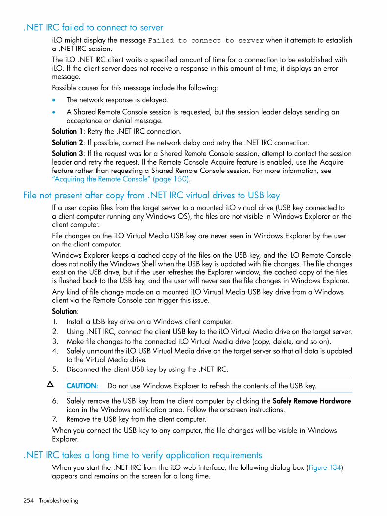
.NET IRC failed to connect to serveriLO might display the message Failed to connect to server when it attempts to establisha .NET IRC session.The iLO .NET IRC client waits a specified amount of time for a connection to be established withiLO. If the client server does not receive a response in this amount of time, it displays an errormessage.Possible causes for this message include the following:
• The network response is delayed.
• A Shared Remote Console session is requested, but the session leader delays sending anacceptance or denial message.
Solution 1: Retry the .NET IRC connection.Solution 2: If possible, correct the network delay and retry the .NET IRC connection.Solution 3: If the request was for a Shared Remote Console session, attempt to contact the sessionleader and retry the request. If the Remote Console Acquire feature is enabled, use the Acquirefeature rather than requesting a Shared Remote Console session. For more information, see“Acquiring the Remote Console” (page 150).
File not present after copy from .NET IRC virtual drives to USB keyIf a user copies files from the target server to a mounted iLO virtual drive (USB key connected toa client computer running any Windows OS), the files are not visible in Windows Explorer on theclient computer.File changes on the iLO Virtual Media USB key are never seen in Windows Explorer by the useron the client computer.Windows Explorer keeps a cached copy of the files on the USB key, and the iLO Remote Consoledoes not notify the Windows Shell when the USB key is updated with file changes. The file changesexist on the USB drive, but if the user refreshes the Explorer window, the cached copy of the filesis flushed back to the USB key, and the user will never see the file changes in Windows Explorer.Any kind of file change made on a mounted iLO Virtual Media USB key drive from a Windowsclient via the Remote Console can trigger this issue.Solution:1. Install a USB key drive on a Windows client computer.2. Using .NET IRC, connect the client USB key to the iLO Virtual Media drive on the target server.3. Make file changes to the connected iLO Virtual Media drive (copy, delete, and so on).4. Safely unmount the iLO USB Virtual Media drive on the target server so that all data is updated
to the Virtual Media drive.5. Disconnect the client USB key by using the .NET IRC.
CAUTION: Do not use Windows Explorer to refresh the contents of the USB key.
6. Safely remove the USB key from the client computer by clicking the Safely Remove Hardwareicon in the Windows notification area. Follow the onscreen instructions.
7. Remove the USB key from the client computer.When you connect the USB key to any computer, the file changes will be visible in WindowsExplorer.
.NET IRC takes a long time to verify application requirementsWhen you start the .NET IRC from the iLO web interface, the following dialog box (Figure 134)appears and remains on the screen for a long time.
254 Troubleshooting
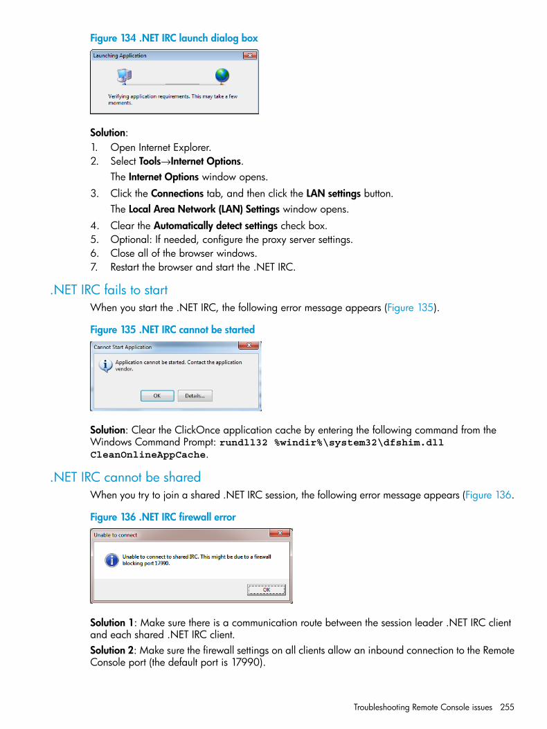
Figure 134 .NET IRC launch dialog box
Solution:1. Open Internet Explorer.2. Select Tools→Internet Options.
The Internet Options window opens.3. Click the Connections tab, and then click the LAN settings button.
The Local Area Network (LAN) Settings window opens.4. Clear the Automatically detect settings check box.5. Optional: If needed, configure the proxy server settings.6. Close all of the browser windows.7. Restart the browser and start the .NET IRC.
.NET IRC fails to startWhen you start the .NET IRC, the following error message appears (Figure 135).
Figure 135 .NET IRC cannot be started
Solution: Clear the ClickOnce application cache by entering the following command from theWindows Command Prompt: rundll32 %windir%\system32\dfshim.dllCleanOnlineAppCache.
.NET IRC cannot be sharedWhen you try to join a shared .NET IRC session, the following error message appears (Figure 136.
Figure 136 .NET IRC firewall error
Solution 1: Make sure there is a communication route between the session leader .NET IRC clientand each shared .NET IRC client.Solution 2: Make sure the firewall settings on all clients allow an inbound connection to the RemoteConsole port (the default port is 17990).
Troubleshooting Remote Console issues 255
Troubleshooting SSH issuesThe following sections discuss troubleshooting SSH issues.
Initial PuTTY input slowDuring the initial connection to iLO through a PuTTY client, input is accepted slowly for approximately5 seconds.Solution: Change the configuration options in the client. Clear the Disable Nagle's algorithm checkbox in the low-level TCP connection options.
PuTTY client unresponsiveWhen you are using a PuTTY client with the Shared Network Port, the PuTTY session might becomeunresponsive when a large amount of data is transferred or when you are using a Virtual SerialPort and Remote Console.Solution: Close the PuTTY client and restart the session.
SSH text support from text-based Remote Console sessionSSH access from the text-based Remote Console supports the standard 80 x 25 configuration ofthe text screen. This mode is compatible for the text-based Remote Console for most text-modeinterfaces. Extended text configuration beyond the 80 x 25 configuration is not displayed correctlywhen using SSH. HP recommends configuring the text application in 80 x 25 mode or using thegraphical Remote Console.
iLO Virtual Floppy media applet unresponsiveThe iLO Virtual Floppy media applet can become unresponsive if the physical floppy diskettecontains media errors.Solution: To prevent the iLO Virtual Floppy media applet from becoming unresponsive, run a utilitysuch as CHKDSK.EXE to check the physical floppy disk media for errors. If the physical mediacontains errors, load the floppy disk image onto a new physical floppy diskette.
Troubleshooting text-based Remote Console issuesThe following sections discuss items to be aware of when attempting to resolve text-based RemoteConsole issues.
Unable to view Linux installer in text-based Remote ConsoleWhen installing Linux from the text console, the initial installation screen might not appear becausethe screen is in graphics mode.Solution: To correct this and proceed with the installation, do one of the following:
• For most versions of Linux, enter linux text nofb.The characters that you enter do not appear.After you enter the command, the screen changes from graphics mode to text mode, displayingthe screen.
• For SLES, press F2 and the down arrow from the text console. The text mode is selected andthe screen appears.
Unable to pass data through SSH terminalIf you use an SSH terminal to access the text console, SSH might intercept keystroke data and notpass the action to the text-based Remote Console. When this occurs, it appears as if the keystrokedid not perform its function.
256 Troubleshooting

Solution: Disable any SSH terminal shortcuts.
VSP-driven selection during the serial timeout window sends output to BIOS redirectinstead of VSP
The /etc/grub.conf file includes an option for a serial timeout window (terminal--timeout=10 serial console). This setting provides a window of time to select a key strokeon the VSP or on the VGA console, and then the menu is output to the corresponding device. TheBIOS serial redirect intercepts VSP keystrokes during this timeout window.Solution: To work around this issue, do not press a key for a VSP-driven selection during the10-second timeout or turn off BIOS redirection to the VSP.
Scrolling and text appear irregular during BIOS redirectionDuring BIOS redirection, the scrolling might not work properly. When you enter commands inRBSU, the text might overwrite itself on the bottom line of the terminal window.Solution: The BIOS expects and controls a fixed 80x24 character window. When redirected tothe serial port, the BIOS still expects and controls a fixed 80x24 character window. If the VSPclient being used (SSH, HyperTerminal, or other terminal emulator) can resize the window to asize other than 80x24, scrolling becomes confused and the screen output appears garbled. Toavoid this issue, configure the terminal emulator for a window size of exactly 80x24.
Troubleshooting Remote Support issuesThe following sections discuss troubleshooting Remote Support issues.
SSL Bio Error during Insight RS registrationIssue: The following error occurs when you try to register a ProLiant Gen8 server with Insight RS:SSL Bio Error.Suggested action: Navigate to the Information→Diagnostics page in the iLO web interface, andthen click the Reset iLO button. When the reset is finished, log in to the iLO web interface and retrythe registration procedure.Clicking Reset iLO does not make any configuration changes, but it terminates any active connectionsto iLO and completes any firmware updates in progress. You must have the Configure iLO Settingsprivilege to reset iLO by using this option.
ProLiant Gen8 server identified in Insight Online as <product name>_<serial number>and in Insight RS as <serial number>
Issue: If a server is registered for Remote Support before the iLO is aware of the server name,Insight Online assigns a server name in the format <product name>_<serial number>, and InsightRS identifies the server by its serial number. To update the server name with a user-friendly servername, iLO must be made aware of the server name.Suggested action: Complete the following procedure.1. Do one of the following:
• Verify that AMS is enabled and the operating system is running.
• Update the Server Name on the Administration→Access Settings page in the iLO webinterface.
Troubleshooting Remote Support issues 257
2. Depending on your configuration, do one of the following:• For configurations with iLO firmware 1.30 or later and Insight RS 7.0.8 or later, no
additional action is required. iLO automatically detects the server name and forwards itto Insight RS and Insight Online for display.
• For configurations with iLO firmware versions earlier than 1.30, and Insight RS 7.0.8 orlater, no additional action is required. iLO automatically detects the server name duringthe next data collection. Data collection occurs automatically every 30 days, and can beinitiated immediately from the Remote Support→Data Collections page in the iLO webinterface. For instructions, see “Sending Data Collection information” (page 106). Theserver name is forwarded to Insight RS and Insight Online during the data collectionprocess.
• For configurations with Insight RS 7.0.5: Unregister the Gen8 server, and then re-registerthe server.
ProLiant Gen8 server OS name and version are not listed in Insight RS or InsightOnline
Issue: If a server is registered for Remote Support when the OS and AMS are not running (forexample, during an Intelligent Provisioning registration), iLO is unable to determine what OS wasinstalled. To update the Insight RS and Insight Online OS information, iLO must acquire the OSinformation from AMS.Suggested action: Complete the following procedure.1. Verify the following:
• iLO firmware 1.20 or later is installed.
• AMS is enabled and the operating system is running.
• Verify that Insight RS 7.0.8 or later is installed on the Hosting Device.
• Verify that the RIBCL credentials for the server are entered in the Insight RS Console andare associated with the ProLiant Gen8 server.If you did not enter the RIBCL credentials in the Insight RS Console before registering aProLiant Gen8 server, follow the procedure in the HP Insight Remote Support and InsightOnline Setup Guide for ProLiant Gen8 Servers and BladeSystem c-Class Enclosures.
2. Initiate a data collection from the Remote Support→Data Collections page in the iLO webinterface. For instructions, see “Sending Data Collection information” (page 106). The OSname and version are forwarded to Insight RS and Insight Online during the data collectionprocess.
When you use Insight Online, the OS name and version are always listed on the DeviceConfiguration Details page if AMS is installed and the OS was running during the most recent datacollection transmission.
Troubleshooting miscellaneous issuesThe following sections discuss troubleshooting miscellaneous hardware or software issues.
Cookie sharing between browser instances and iLOiLO uses browser session cookies to distinguish between individual logins—each browser windowappears as a separate user login—while sharing the same active session with iLO. Multiple loginscan confuse the browser. This may appear to be an iLO issue, but it is typical browser behavior.Several processes can cause a browser to open additional windows. Browser windows openedfrom an open browser represent different aspects of the same program in memory. Consequently,each browser window shares properties with the parent, including cookies.
258 Troubleshooting
Shared instancesWhen iLO opens another browser window (for example, the Remote Console or a help file), thiswindow shares the same connection to iLO and the session cookie.The iLO web server makes URL decisions based on each request received. For example, if a requestdoes not have access rights, it is redirected to the login page, regardless of the original request.Web server-based redirection, selecting File→New→Window, or pressing Ctrl+N opens a duplicateinstance of the original browser.
Cookie orderDuring login, the login page builds a browser session cookie that links the window to the appropriatesession in the iLO firmware. The firmware tracks browser logins as separate sessions listed in theActive Sessions section of the iLO Overview page.For example, when User1 logs in, the web server builds the initial frames view, with User1 listedin the top pane, menu items in the left pane, and page data in the lower right pane. When User1clicks from link to link, only the menu items and page data are updated.While User1 is logged in, if User2, opens a browser window on the same client and logs in, thesecond login overwrites the cookie generated in the original User1 session. Assuming that User2is a different user account, a different current frame is built, and a new session is granted. Thesecond session appears in the Active Sessions section of the iLO Overview page as User2.The second login has effectively orphaned the first session by overriding the cookie generatedduring the User1 login. This behavior is the same as closing the User1 browser without clickingthe Sign Out button. The User1 orphaned session is reclaimed when the session timeout expires.Because the current user frame is not refreshed unless the browser is forced to refresh the entirepage, User1 can continue navigating by using the browser window. However, the browser is nowoperating by using the User2 session cookie settings, even though it may not be readily apparent.If User1 continues to navigate in this mode (User1 and User2 sharing the same process becauseUser2 logged in and reset the session cookie), the following can occur:
• User1 session behaves consistently with the privileges assigned to User2.
• User1 activity keeps User2 session alive, but User1 session can time out unexpectedly.
• Logging out of either window causes both sessions to end. The next activity in the other windowcan redirect the user to the login page as if a session timeout or premature timeout occurred.
• Clicking Sign Out from the second session (User2) results in the following warning message:Logging out: unknown page to display before redirecting the user tothe login page.
• If User2 logs out and then logs back in as User3, User1 assumes the User3 session.
• If User1 is at login, and User2 is logged in, User1 can alter the URL to redirect to the indexpage. It appears as if User1 has accessed iLO without logging in.
These behaviors continue as long as the duplicate windows are open. All activities are attributedto the same user, using the last session cookie set.
Displaying the current session cookieAfter logging in, you can force the browser to display the current session cookie by entering thefollowing in the URL navigation bar:javascript:alert(document.cookie)
The first field visible is the session ID. If the session ID is the same among the different browserwindows, these windows are sharing the same iLO session.You can force the browser to refresh and reveal your true identity by pressing F5, selectingView→Refresh, or clicking the Refresh button.
Troubleshooting miscellaneous issues 259
Preventing cookie-related issuesTo prevent these issues:
• Start a new browser for each login by double-clicking the browser icon or shortcut.
• Click the Sign Out button to close the iLO session before you close the browser window.
Unable to get SNMP information from HP SIMSolution: The agents running on the managed server supply SNMP information to HP SIM. Foragents to pass information through iLO, iLO device drivers must be installed. For installationinstructions, see “Installing the iLO drivers” (page 22).If you have installed the drivers and agents for iLO, verify that iLO and the management PC areon the same subnet. You can verify this quickly by pinging iLO from the management PC. Consultyour network administrator for proper routes to access the iLO network interface.
Unable to upgrade iLO firmware• Solution 1: If you attempt to upgrade the iLO firmware by using the iLO web interface, and it
does not respond, does not accept the firmware upgrade, or is stopped before a successfulupgrade, try reinstalling the firmware after you complete the following diagnostic steps:1. Attempt to connect to iLO through the web browser. If you cannot connect, there is a
communication issue.2. Attempt to ping iLO. If you are successful, the network is working.
• Solution 2: If an incorrect file is used to flash the iLO firmware by using the iLO web interface,the following error message is displayed:The last firmware update attempt was not successful. Ready for thenext update.
If this error occurs, click the Clear Error button to reset the flash process, and then try thefirmware update again with the correct firmware file. If you do not clear the error, the sameerror might occur even when you use the correct firmware file.
• Solution 3: If a connection error occurs after you install a firmware update by using the iLOweb interface, clear the browser cache.
• Solution 4: Try a different firmware update method. For information about the methods thatyou can use to update the firmware, see “Updating firmware” (page 25).
iLO network Failed Flash RecoveryMost firmware upgrades finish successfully. In the unlikely event of server power loss during aniLO firmware upgrade, iLO might be recoverable when power is restored.When the computer is booting, the kernel performs image validation on the main image. If theimage is corrupted or incomplete, the kernel enters Failed Flash Recovery. Failed Flash Recoveryactivates an FTP server within iLO. The FTP server enables you to send an image to iLO forprogramming. The FTP server does not provide any other services.A network client can connect to the FTP server. The user name for the connection is test, and thepassword is flash. To send a firmware image to iLO, use the FTP client PUT command. Afterreceiving the image, iLO validates the image. If the image is a complete, signed, and valid firmwareimage, the kernel begins programming the FLASH partition.After the image is completely programmed into the FLASH partition, reset iLO by issuing the RESETcommand to the iLO FTP server.Example:F:\ilo>ftp 192.168.1.2Connected to 192.168.1.2.
260 Troubleshooting
220 FTP Recovery server ready.User (192.168.1.2:(none)): ftp331 Password required.Password:231 Logged in.ftp> put iLO.bin200 Ok.150 ready for file226-Checking file226-File acceptable226-Flashing 3% complete226-Flashing 4% complete226-Flashing 6% complete...226-Flashing 97% complete226-Flashing 99% complete226-Flashing 100% complete226-Flashing completed226 Closing fileftp: 8388608 bytes sent in 1.38Seconds 6100.81 Kbytes/sec.ftp> quote reset221 Goodbye (reset).Connection closed by remote host.ftp> quit
Testing SSLThe following test checks for the correct security prompt. A nonworking server will proceed to aPage cannot be displayed message. If this test fails, your domain controller is not acceptingSSL connections and probably has not been issued a certificate.1. Open a browser and navigate to https://<domain controller>:636.
You can use <domain> instead of <domain controller>, which accesses the DNS anddetermines which domain controller is handling requests for the domain. Test multiple domaincontrollers to verify that all of them have been issued a certificate.
2. If SSL is operating correctly on the domain controller (a certificate has been issued), you areprompted with a security message that asks whether you want to proceed with accessing thesite or view the server certificate. Clicking Yes does not display a webpage, which is normal.This process is automatic, but might require rebooting. To avoid rebooting:a. Open the MMC.b. Add the certificates snap-in.c. When prompted, select Computer Account for the type of certificates you want to view.d. Click OK to return to the certificates snap-in.e. Select the Personal→Certificates folder.f. Right-click the folder and select Request New Certificate.g. Verify that the Type is domain controller, and click Next until a certificate is issued.
You can also use the Microsoft Ldp.exe tool to verify SSL connections. For more information aboutthe LDP tool, see your Microsoft documentation.An old certificate can cause issues with SSL on the domain controller when it points to a previouslytrusted CA with the same name. This situation is rare but might happen if a certificate service isadded and removed, and then added again on the domain controller. To remove old certificatesand issue a new one, follow the instructions in step 2.
Troubleshooting miscellaneous issues 261
Resetting iLOIn some cases, it might be necessary to reset iLO; for example, if iLO is not responding to thebrowser.iLO might reset itself in certain instances. For example, an internal iLO watchdog timer resets if thefirmware detects an iLO issue. If a firmware upgrade is completed or a network setting is changed,iLO also resets.To reset iLO, use one of the following methods:
• Click Reset on the Information→Diagnostics page in the iLO web interface. For moreinformation, see “Using iLO diagnostics” (page 142).
• Use the CLI or HPONCFG. For instructions, see the HP iLO 4 Scripting and Command LineGuide.
• The HP Insight Management Agents 5.40 and later have the ability to reset iLO. Select theReset iLO option on the HP Management Agent page in the iLO section.
• Click Apply on the Network→iLO Dedicated Network Port or Shared Network Port→Generalpage to manually force the iLO management processor to reset. If the Apply button is notavailable, change a setting, change it back, and then click Apply to reset iLO without changingthe configuration.
Click the following link for a video demonstration of this feature: Resetting iLO. For more HPiLO videos, see the HP iLO University Videos website: http://www.hp.com/go/ilo/videos.If none of these methods is available or working as expected, you must power down the serverand disconnect the power supplies completely.
Resetting iLO to the factory default settings by using iLO RBSU1. Restart or power on the server.2. Press F8 when prompted during POST.
iLO RBSU starts.3. Select File→Set Defaults.
iLO RBSU prompts you to confirm the request.4. Press F10 to continue.
iLO RBSU displays the following message:After setting to factory defaults, iLO 4 will be reset and this utility will exit.
5. Press Enter.iLO resets and the server boot process finishes.
Server name still present after System Erase Utility is executedThe server name, as shown on the iLO Overview page, is the installed host operating system name.If the Insight Management Agents are installed on the server, the agents will obtain the host nameand update it on the iLO web interface page.To remove the server name after the redeployment of a server, do one of the following:
• Load the HP Insight Management Agents to update the server name.
• Use the iLO RBSU Reset to Factory Defaults feature to clear the server name.
CAUTION: This procedure clears all iLO configuration information, not just the Server Nameinformation.
• Change the server name on the Administration→Access Settings→Access Options page in theiLO web interface.
262 Troubleshooting
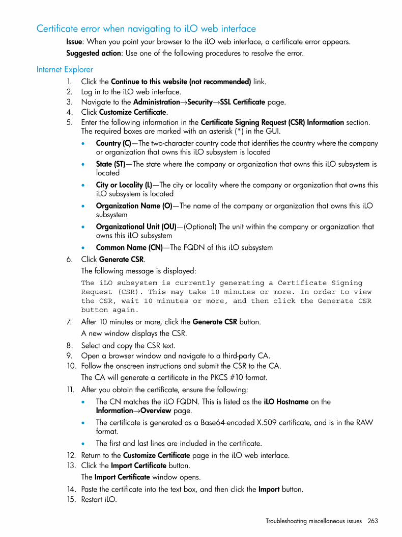
Certificate error when navigating to iLO web interfaceIssue: When you point your browser to the iLO web interface, a certificate error appears.Suggested action: Use one of the following procedures to resolve the error.
Internet Explorer1. Click the Continue to this website (not recommended) link.2. Log in to the iLO web interface.3. Navigate to the Administration→Security→SSL Certificate page.4. Click Customize Certificate.5. Enter the following information in the Certificate Signing Request (CSR) Information section.
The required boxes are marked with an asterisk (*) in the GUI.• Country (C)—The two-character country code that identifies the country where the company
or organization that owns this iLO subsystem is located• State (ST)—The state where the company or organization that owns this iLO subsystem is
located• City or Locality (L)—The city or locality where the company or organization that owns this
iLO subsystem is located• Organization Name (O)—The name of the company or organization that owns this iLO
subsystem• Organizational Unit (OU)—(Optional) The unit within the company or organization that
owns this iLO subsystem• Common Name (CN)—The FQDN of this iLO subsystem
6. Click Generate CSR.The following message is displayed:The iLO subsystem is currently generating a Certificate SigningRequest (CSR). This may take 10 minutes or more. In order to viewthe CSR, wait 10 minutes or more, and then click the Generate CSRbutton again.
7. After 10 minutes or more, click the Generate CSR button.A new window displays the CSR.
8. Select and copy the CSR text.9. Open a browser window and navigate to a third-party CA.10. Follow the onscreen instructions and submit the CSR to the CA.
The CA will generate a certificate in the PKCS #10 format.11. After you obtain the certificate, ensure the following:
• The CN matches the iLO FQDN. This is listed as the iLO Hostname on theInformation→Overview page.
• The certificate is generated as a Base64-encoded X.509 certificate, and is in the RAWformat.
• The first and last lines are included in the certificate.12. Return to the Customize Certificate page in the iLO web interface.13. Click the Import Certificate button.
The Import Certificate window opens.14. Paste the certificate into the text box, and then click the Import button.15. Restart iLO.
Troubleshooting miscellaneous issues 263

Firefox1. Click the I Understand the Risks link to expand the section, and then click Add Exception.2. In the Add Security Exception dialog box, enter https://<iLO hostname or IP
address> in the Location box.3. Click Confirm Security Exception to resolve the security warning.
264 Troubleshooting
8 Support and other resourcesInformation to collect before you contact HP
Be sure to have the following information available before you contact HP:
• Software product name
• Hardware product model number
• Operating system type and version
• Applicable error message
• Third-party hardware or software
• Technical support registration number (if applicable)
• Active Health System logFor more information, see “Using the HP Active Health System” (page 139).
How to contact HPUse the following methods to contact HP technical support:
• See the Contact HP worldwide website:http://www.hp.com/go/assistance
• Use the Contact hp link on the HP Support Center website:http://www.hp.com/go/hpsc
• In the United States, call +1 800 334 5144 to contact HP by telephone. This service is available24 hours a day, 7 days a week. For continuous quality improvement, conversations might berecorded or monitored.
Registering for Software Technical Support and Update ServiceInsight Management software products include 1 year of 24 x 7 HP Software Technical Supportand Update Service. This service provides access to HP technical resources for assistance inresolving software implementation or operations problems.The service also provides access to software updates and reference manuals in electronic format.With this service, iLO Advanced and iLO Advanced for BladeSystem customers benefit fromexpedited problem resolution as well as proactive notification and delivery of software updates.For more information about this service, see the following website: http://www.hp.com/services/insight.If you received a license entitlement certificate, registration for this service occurs after onlineredemption of the license certificate or key.
How to use Software Technical Support and Update ServiceAfter you are registered, you will receive a service contract in the mail. The contract contains theCustomer Service phone number and your SAID. You will need your SAID when you call fortechnical support. By using your SAID, you can also go to the HP Support Center website to viewyour contract online.
HP Support CenterJoin the discussion. The HP Support Center at http://www.hp.com/go/hpsc is a community-based,user-supported tool for HP customers to participate in discussions among the customer community
Information to collect before you contact HP 265
about HP products. For discussions related to iLO Advanced and iLO Advanced for BladeSystemsoftware, see the Management Software and System Tools area.
HP authorized resellersFor the name of the nearest HP authorized reseller, see the following sources:
• In the United States, see the HP U.S. service locator website:http://www.hp.com/service_locator
• In other locations, see the Contact HP worldwide website:http://www.hp.com/go/assistance
Related information
Documents• HP iLO 4 Scripting and Command Line Guide
• HP iLO 4 Release Notes
• HP ROM-Based Setup Utility User Guide
• HP Intelligent Provisioning User Guide
• HP Scripting Toolkit for Linux User Guide
• HP Scripting Toolkit for Windows User Guide
• HP Smart Update Firmware DVD User Guide
• HP Smart Update Manager User Guide
• HP Service Pack for ProLiant User Guide
• HP Insight Management Agents User Guide
• HP Insight Management Agents Installation Guide
• HP Systems Insight Manager User Guide
• HP BladeSystem Onboard Administrator User Guide
• HP ProLiant Gen8 Troubleshooting Guide, Volume I: Troubleshooting
• HP Insight Remote Support Installation and Configuration Guide
• HP Insight Remote Support Monitored Devices Configuration Guide
• HP Insight Remote Support and Insight Online Setup Guide for ProLiant Gen8 Servers
Websites• HP ProLiant Gen8 Server Management: http://www.hp.com/go/proliantgen8/docs
• HP iLO Management Engine: http://www.hp.com/go/ilomgmtengine/docs
• HP Intelligent Provisioning: http://www.hp.com/go/intelligentprovisioning/docs
• HP Insight Remote Support: www.hp.com/go/insightremotesupport/docs
• HP SUM: http://www.hp.com/go/hpsum
• HP Service Pack for ProLiant: http://www.hp.com/go/spp/documentation
• HP iLO 4: http://www.hp.com/go/ilo/docs
• HP iLO University videos: http://www.hp.com/go/ilo/videos
• HP Systems Insight Manager: http://www.hp.com/go/hpsim
266 Support and other resources

• HP Onboard Administrator: http://www.hp.com/go/oa
• HP VMware Vibs Depot:http://vibsdepot.hp.com
Related information 267

9 Documentation feedbackHP is committed to providing documentation that meets your needs. To help us improve thedocumentation, send any errors, suggestions, or comments to Documentation Feedback([email protected]). Include the document title and part number, version number, or the URLwhen submitting your feedback.
268 Documentation feedback
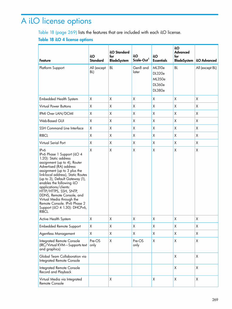
A iLO license optionsTable 18 (page 269) lists the features that are included with each iLO license.
Table 18 iLO 4 license options
iLO Advanced
iLOAdvanced
iLOEssentials
iLOScale-Out1
iLO StandardforBladeSystem
iLOStandardFeature
forBladeSystem
All (except BL)BLML310eGen8 andlater
BLAll (exceptBL)
Platform SupportDL320eML350eDL360eDL380e
XXXXXXEmbedded Health System
XXXXXXVirtual Power Buttons
XXXXXXIPMI Over LAN/DCMI
XXXXXXWeb-Based GUI
XXXXXXSSH Command Line Interface
XXXXXXRIBCL
XXXXXXVirtual Serial Port
XXXXXXIPv6IPv6 Phase 1 Support (iLO 41.20): Static addressassignment (up to 4), RouterAdvertised (RA) addressassignment (up to 3 plus thelink-local address), Static Routes(up to 3), Default Gateway (1),enables the following iLOapplications/clients:HTTP/HTTPS, SSH, SNTP,DDNS, Remote Console, andVirtual Media through theRemote Console. IPv6 Phase 2Support (iLO 4 1.30): DHCPv6,RIBCL.
XXXXXXActive Health System
XXXXXXEmbedded Remote Support
XXXXXXAgentless Management
XXXPre-OSonly
XPre-OSonly
Integrated Remote Console(IRC/Virtual KVM—Supports textand graphics)
XXGlobal Team Collaboration viaIntegrated Remote Console
XXIntegrated Remote ConsoleRecord and Playback
XXXXVirtual Media via IntegratedRemote Console
269
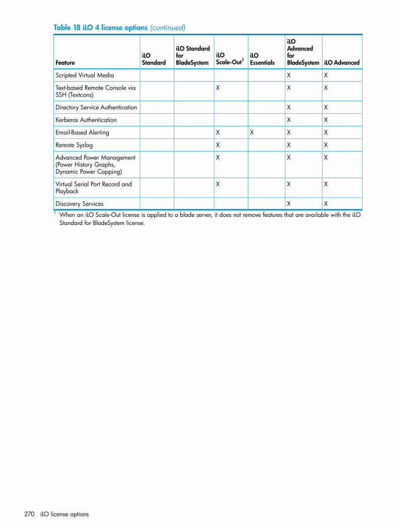
Table 18 iLO 4 license options (continued)
iLO Advanced
iLOAdvancedforBladeSystem
iLOEssentials
iLOScale-Out1
iLO StandardforBladeSystem
iLOStandardFeature
XXScripted Virtual Media
XXXText-based Remote Console viaSSH (Textcons)
XXDirectory Service Authentication
XXKerberos Authentication
XXXXEmail-Based Alerting
XXXRemote Syslog
XXXAdvanced Power Management(Power History Graphs,Dynamic Power Capping)
XXXVirtual Serial Port Record andPlayback
XXDiscovery Services1 When an iLO Scale-Out license is applied to a blade server, it does not remove features that are available with the iLO
Standard for BladeSystem license.
270 iLO license options
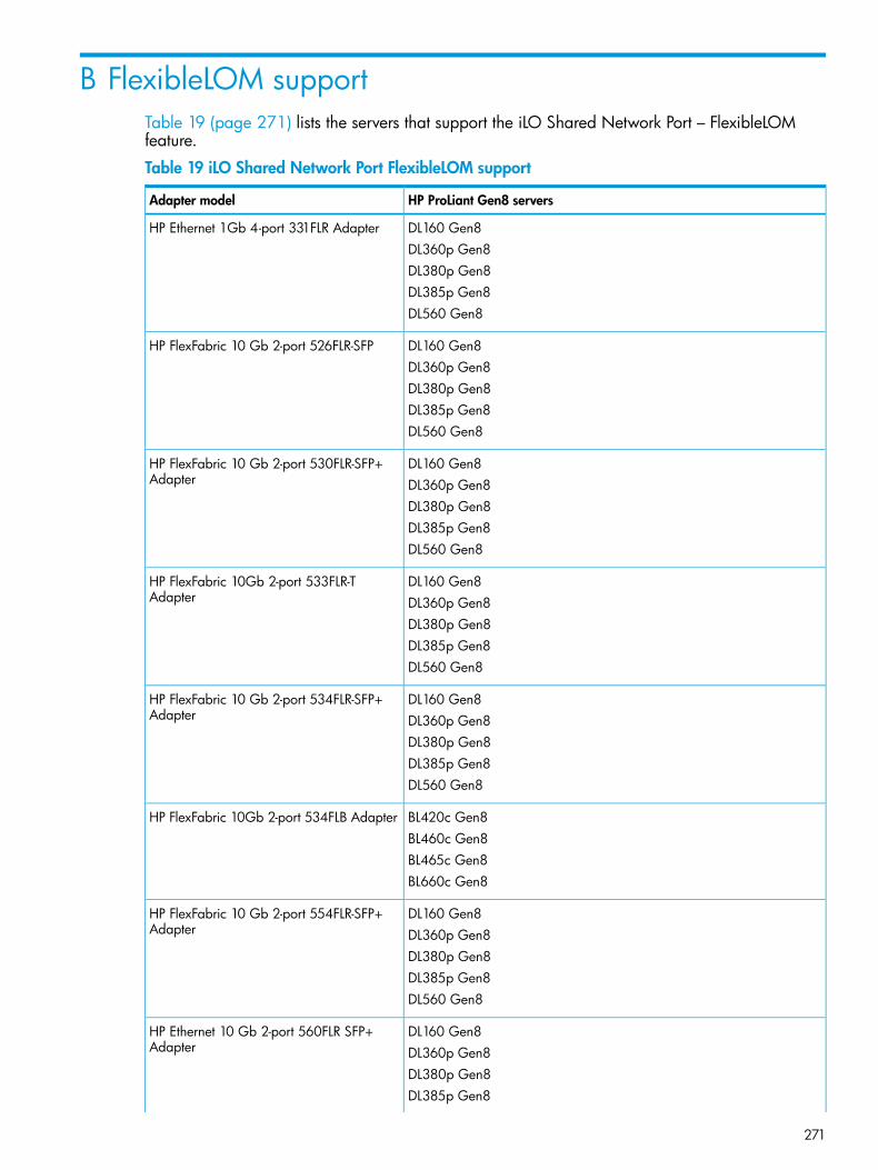
B FlexibleLOM supportTable 19 (page 271) lists the servers that support the iLO Shared Network Port – FlexibleLOMfeature.
Table 19 iLO Shared Network Port FlexibleLOM support
HP ProLiant Gen8 serversAdapter model
DL160 Gen8HP Ethernet 1Gb 4-port 331FLR AdapterDL360p Gen8DL380p Gen8DL385p Gen8DL560 Gen8
DL160 Gen8HP FlexFabric 10 Gb 2-port 526FLR-SFPDL360p Gen8DL380p Gen8DL385p Gen8DL560 Gen8
DL160 Gen8HP FlexFabric 10 Gb 2-port 530FLR-SFP+Adapter DL360p Gen8
DL380p Gen8DL385p Gen8DL560 Gen8
DL160 Gen8HP FlexFabric 10Gb 2-port 533FLR-TAdapter DL360p Gen8
DL380p Gen8DL385p Gen8DL560 Gen8
DL160 Gen8HP FlexFabric 10 Gb 2-port 534FLR-SFP+Adapter DL360p Gen8
DL380p Gen8DL385p Gen8DL560 Gen8
BL420c Gen8HP FlexFabric 10Gb 2-port 534FLB AdapterBL460c Gen8BL465c Gen8BL660c Gen8
DL160 Gen8HP FlexFabric 10 Gb 2-port 554FLR-SFP+Adapter DL360p Gen8
DL380p Gen8DL385p Gen8DL560 Gen8
DL160 Gen8HP Ethernet 10 Gb 2-port 560FLR SFP+Adapter DL360p Gen8
DL380p Gen8DL385p Gen8
271
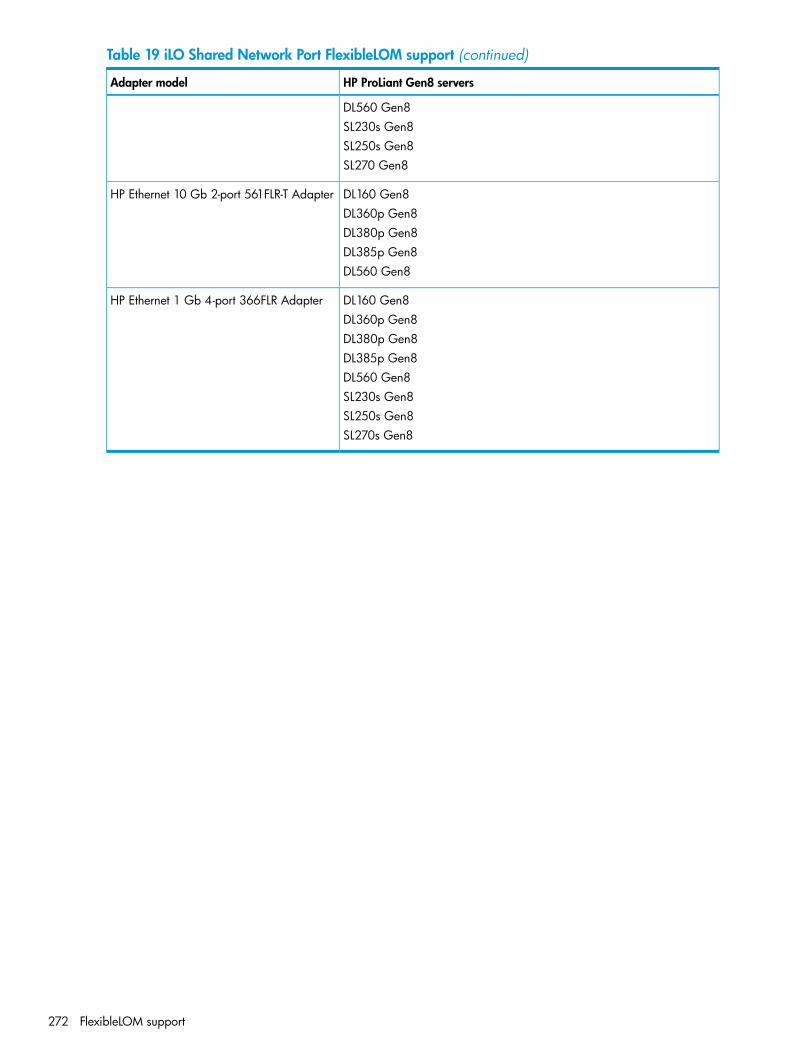
Table 19 iLO Shared Network Port FlexibleLOM support (continued)
HP ProLiant Gen8 serversAdapter model
DL560 Gen8SL230s Gen8SL250s Gen8SL270 Gen8
DL160 Gen8HP Ethernet 10 Gb 2-port 561FLR-T AdapterDL360p Gen8DL380p Gen8DL385p Gen8DL560 Gen8
DL160 Gen8HP Ethernet 1 Gb 4-port 366FLR AdapterDL360p Gen8DL380p Gen8DL385p Gen8DL560 Gen8SL230s Gen8SL250s Gen8SL270s Gen8
272 FlexibleLOM support
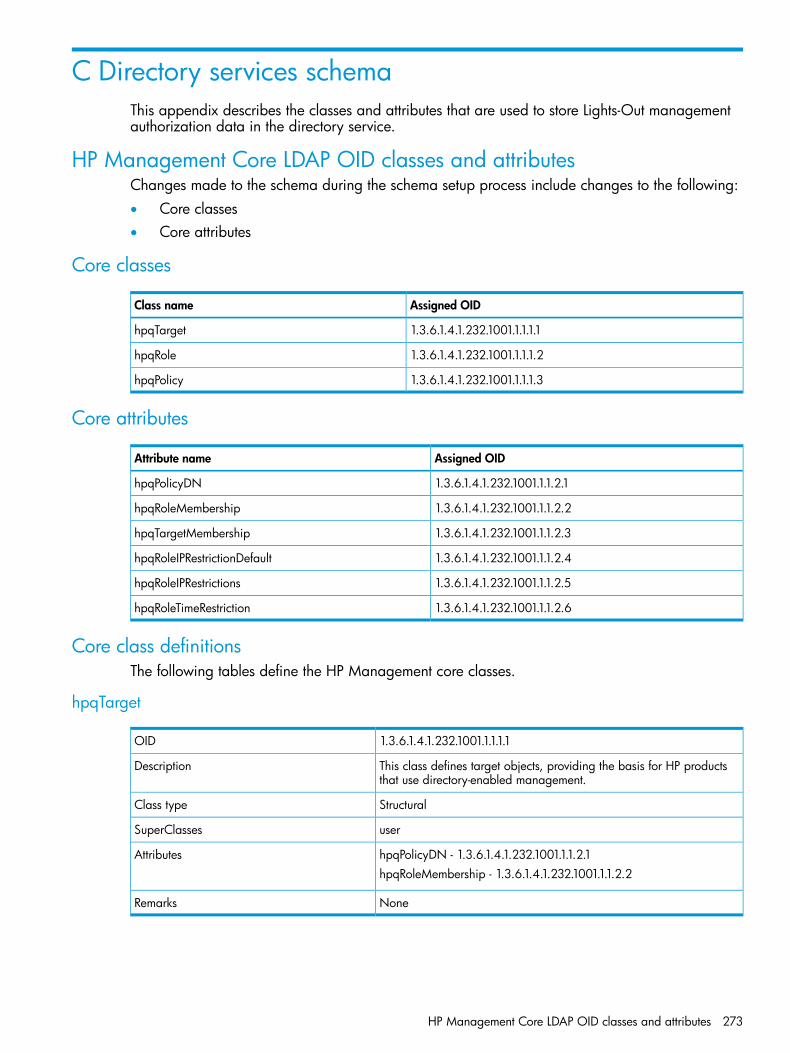
C Directory services schemaThis appendix describes the classes and attributes that are used to store Lights-Out managementauthorization data in the directory service.
HP Management Core LDAP OID classes and attributesChanges made to the schema during the schema setup process include changes to the following:• Core classes• Core attributes
Core classes
Assigned OIDClass name
1.3.6.1.4.1.232.1001.1.1.1.1hpqTarget
1.3.6.1.4.1.232.1001.1.1.1.2hpqRole
1.3.6.1.4.1.232.1001.1.1.1.3hpqPolicy
Core attributes
Assigned OIDAttribute name
1.3.6.1.4.1.232.1001.1.1.2.1hpqPolicyDN
1.3.6.1.4.1.232.1001.1.1.2.2hpqRoleMembership
1.3.6.1.4.1.232.1001.1.1.2.3hpqTargetMembership
1.3.6.1.4.1.232.1001.1.1.2.4hpqRoleIPRestrictionDefault
1.3.6.1.4.1.232.1001.1.1.2.5hpqRoleIPRestrictions
1.3.6.1.4.1.232.1001.1.1.2.6hpqRoleTimeRestriction
Core class definitionsThe following tables define the HP Management core classes.
hpqTarget
1.3.6.1.4.1.232.1001.1.1.1.1OID
This class defines target objects, providing the basis for HP productsthat use directory-enabled management.
Description
StructuralClass type
userSuperClasses
hpqPolicyDN - 1.3.6.1.4.1.232.1001.1.1.2.1AttributeshpqRoleMembership - 1.3.6.1.4.1.232.1001.1.1.2.2
NoneRemarks
HP Management Core LDAP OID classes and attributes 273
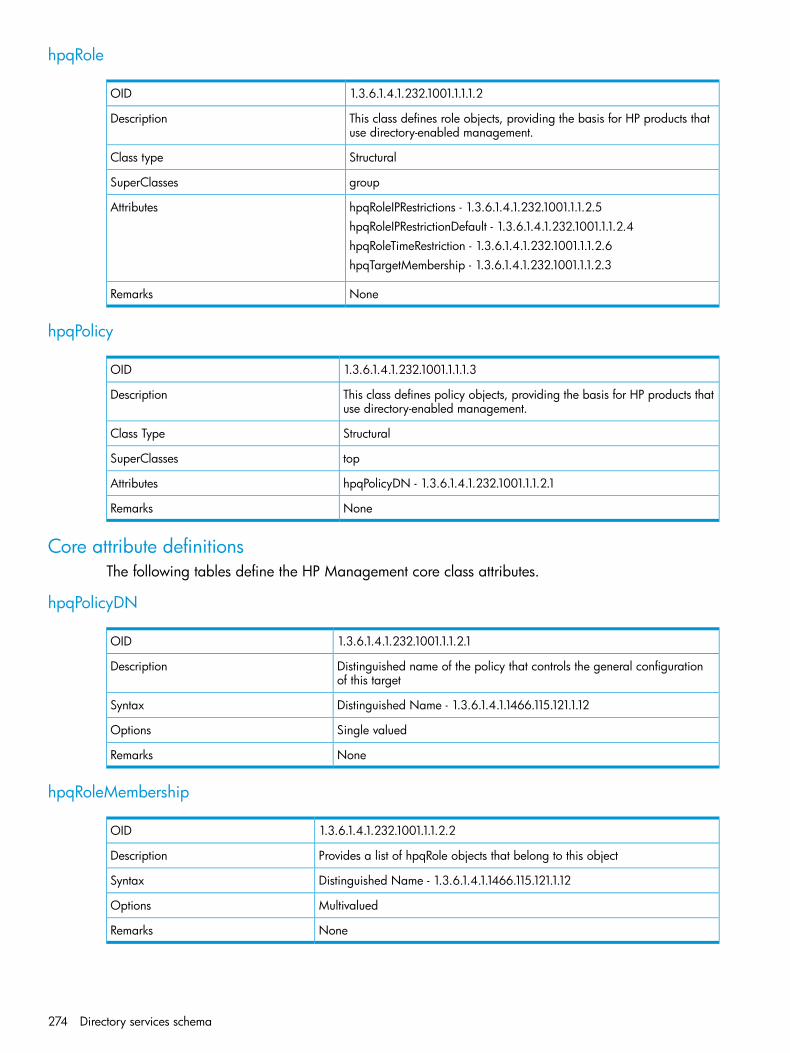
hpqRole
1.3.6.1.4.1.232.1001.1.1.1.2OID
This class defines role objects, providing the basis for HP products thatuse directory-enabled management.
Description
StructuralClass type
groupSuperClasses
hpqRoleIPRestrictions - 1.3.6.1.4.1.232.1001.1.1.2.5AttributeshpqRoleIPRestrictionDefault - 1.3.6.1.4.1.232.1001.1.1.2.4hpqRoleTimeRestriction - 1.3.6.1.4.1.232.1001.1.1.2.6hpqTargetMembership - 1.3.6.1.4.1.232.1001.1.1.2.3
NoneRemarks
hpqPolicy
1.3.6.1.4.1.232.1001.1.1.1.3OID
This class defines policy objects, providing the basis for HP products thatuse directory-enabled management.
Description
StructuralClass Type
topSuperClasses
hpqPolicyDN - 1.3.6.1.4.1.232.1001.1.1.2.1Attributes
NoneRemarks
Core attribute definitionsThe following tables define the HP Management core class attributes.
hpqPolicyDN
1.3.6.1.4.1.232.1001.1.1.2.1OID
Distinguished name of the policy that controls the general configurationof this target
Description
Distinguished Name - 1.3.6.1.4.1.1466.115.121.1.12Syntax
Single valuedOptions
NoneRemarks
hpqRoleMembership
1.3.6.1.4.1.232.1001.1.1.2.2OID
Provides a list of hpqRole objects that belong to this objectDescription
Distinguished Name - 1.3.6.1.4.1.1466.115.121.1.12Syntax
MultivaluedOptions
NoneRemarks
274 Directory services schema
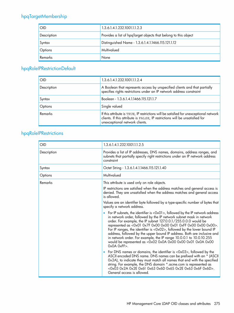
hpqTargetMembership
1.3.6.1.4.1.232.1001.1.1.2.3OID
Provides a list of hpqTarget objects that belong to this objectDescription
Distinguished Name - 1.3.6.1.4.1.1466.115.121.1.12Syntax
MultivaluedOptions
NoneRemarks
hpqRoleIPRestrictionDefault
1.3.6.1.4.1.232.1001.1.1.2.4OID
A Boolean that represents access by unspecified clients and that partiallyspecifies rights restrictions under an IP network address constraint
Description
Boolean - 1.3.6.1.4.1.1466.115.121.1.7Syntax
Single valuedOptions
If this attribute is TRUE, IP restrictions will be satisfied for unexceptional networkclients. If this attribute is FALSE, IP restrictions will be unsatisfied forunexceptional network clients.
Remarks
hpqRoleIPRestrictions
1.3.6.1.4.1.232.1001.1.1.2.5OID
Provides a list of IP addresses, DNS names, domains, address ranges, andsubnets that partially specify right restrictions under an IP network addressconstraint
Description
Octet String - 1.3.6.1.4.1.1466.115.121.1.40Syntax
MultivaluedOptions
This attribute is used only on role objects.RemarksIP restrictions are satisfied when the address matches and general access isdenied. They are unsatisfied when the address matches and general accessis allowed.Values are an identifier byte followed by a type-specific number of bytes thatspecify a network address.
• For IP subnets, the identifier is <0x01>, followed by the IP network addressin network order, followed by the IP network subnet mask in networkorder. For example, the IP subnet 127.0.0.1/255.0.0.0 would berepresented as <0x01 0x7F 0x00 0x00 0x01 0xFF 0x00 0x00 0x00>.For IP ranges, the identifier is <0x02>, followed by the lower bound IPaddress, followed by the upper bound IP address. Both are inclusive andin network order. For example, the IP range 10.0.0.1 to 10.0.10.255would be represented as <0x02 0x0A 0x00 0x00 0x01 0x0A 0x000x0A 0xFF>.
• For DNS names or domains, the identifier is <0x03>, followed by theASCII encoded DNS name. DNS names can be prefixed with an * (ASCII0x2A), to indicate they must match all names that end with the specifiedstring. For example, the DNS domain *.acme.com is represented as<0x03 0x2A 0x2E 0x61 0x63 0x6D 0x65 0x2E 0x63 0x6F 0x6D>.General access is allowed.
HP Management Core LDAP OID classes and attributes 275
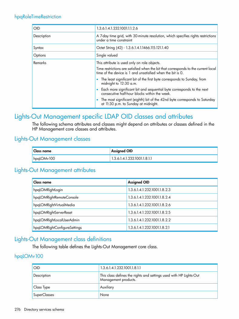
hpqRoleTimeRestriction
1.3.6.1.4.1.232.1001.1.1.2.6OID
A 7-day time grid, with 30-minute resolution, which specifies rights restrictionsunder a time constraint
Description
Octet String {42} - 1.3.6.1.4.1.1466.115.121.1.40Syntax
Single valuedOptions
This attribute is used only on role objects.RemarksTime restrictions are satisfied when the bit that corresponds to the current localtime of the device is 1 and unsatisfied when the bit is 0.
• The least significant bit of the first byte corresponds to Sunday, frommidnight to 12:30 a.m.
• Each more significant bit and sequential byte corresponds to the nextconsecutive half-hour blocks within the week.
• The most significant (eighth) bit of the 42nd byte corresponds to Saturdayat 11:30 p.m. to Sunday at midnight.
Lights-Out Management specific LDAP OID classes and attributesThe following schema attributes and classes might depend on attributes or classes defined in theHP Management core classes and attributes.
Lights-Out Management classes
Assigned OIDClass name
1.3.6.1.4.1.232.1001.1.8.1.1hpqLOMv100
Lights-Out Management attributes
Assigned OIDClass name
1.3.6.1.4.1.232.1001.1.8.2.3hpqLOMRightLogin
1.3.6.1.4.1.232.1001.1.8.2.4hpqLOMRightRemoteConsole
1.3.6.1.4.1.232.1001.1.8.2.6hpqLOMRightVirtualMedia
1.3.6.1.4.1.232.1001.1.8.2.5hpqLOMRightServerReset
1.3.6.1.4.1.232.1001.1.8.2.2hpqLOMRightLocalUserAdmin
1.3.6.1.4.1.232.1001.1.8.2.1hpqLOMRightConfigureSettings
Lights-Out Management class definitionsThe following table defines the Lights-Out Management core class.
hpqLOMv100
1.3.6.1.4.1.232.1001.1.8.1.1OID
This class defines the rights and settings used with HP Lights-OutManagement products.
Description
AuxiliaryClass Type
NoneSuperClasses
276 Directory services schema
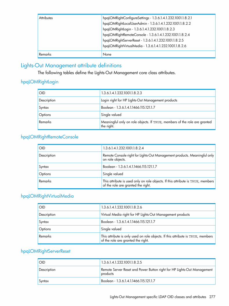
hpqLOMRightConfigureSettings - 1.3.6.1.4.1.232.1001.1.8.2.1AttributeshpqLOMRightLocalUserAdmin - 1.3.6.1.4.1.232.1001.1.8.2.2hpqLOMRightLogin - 1.3.6.1.4.1.232.1001.1.8.2.3hpqLOMRightRemoteConsole - 1.3.6.1.4.1.232.1001.1.8.2.4hpqLOMRightServerReset - 1.3.6.1.4.1.232.1001.1.8.2.5hpqLOMRightVirtualMedia - 1.3.6.1.4.1.232.1001.1.8.2.6
NoneRemarks
Lights-Out Management attribute definitionsThe following tables define the Lights-Out Management core class attributes.
hpqLOMRightLogin
1.3.6.1.4.1.232.1001.1.8.2.3OID
Login right for HP Lights-Out Management productsDescription
Boolean - 1.3.6.1.4.1.1466.115.121.1.7Syntax
Single valuedOptions
Meaningful only on role objects. If TRUE, members of the role are grantedthe right.
Remarks
hpqLOMRightRemoteConsole
1.3.6.1.4.1.232.1001.1.8.2.4OID
Remote Console right for Lights-Out Management products. Meaningful onlyon role objects.
Description
Boolean - 1.3.6.1.4.1.1466.115.121.1.7Syntax
Single valuedOptions
This attribute is used only on role objects. If this attribute is TRUE, membersof the role are granted the right.
Remarks
hpqLOMRightVirtualMedia
1.3.6.1.4.1.232.1001.1.8.2.6OID
Virtual Media right for HP Lights-Out Management productsDescription
Boolean - 1.3.6.1.4.1.1466.115.121.1.7Syntax
Single valuedOptions
This attribute is only used on role objects. If this attribute is TRUE, membersof the role are granted the right.
Remarks
hpqLOMRightServerReset
1.3.6.1.4.1.232.1001.1.8.2.5OID
Remote Server Reset and Power Button right for HP Lights-Out Managementproducts
Description
Boolean - 1.3.6.1.4.1.1466.115.121.1.7Syntax
Lights-Out Management specific LDAP OID classes and attributes 277
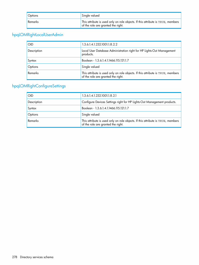
Single valuedOptions
This attribute is used only on role objects. If this attribute is TRUE, membersof the role are granted the right.
Remarks
hpqLOMRightLocalUserAdmin
1.3.6.1.4.1.232.1001.1.8.2.2OID
Local User Database Administration right for HP Lights-Out Managementproducts.
Description
Boolean - 1.3.6.1.4.1.1466.115.121.1.7Syntax
Single valuedOptions
This attribute is used only on role objects. If this attribute is TRUE, membersof the role are granted the right.
Remarks
hpqLOMRightConfigureSettings
1.3.6.1.4.1.232.1001.1.8.2.1OID
Configure Devices Settings right for HP Lights-Out Management products.Description
Boolean - 1.3.6.1.4.1.1466.115.121.1.7Syntax
Single valuedOptions
This attribute is used only on role objects. If this attribute is TRUE, membersof the role are granted the right.
Remarks
278 Directory services schema
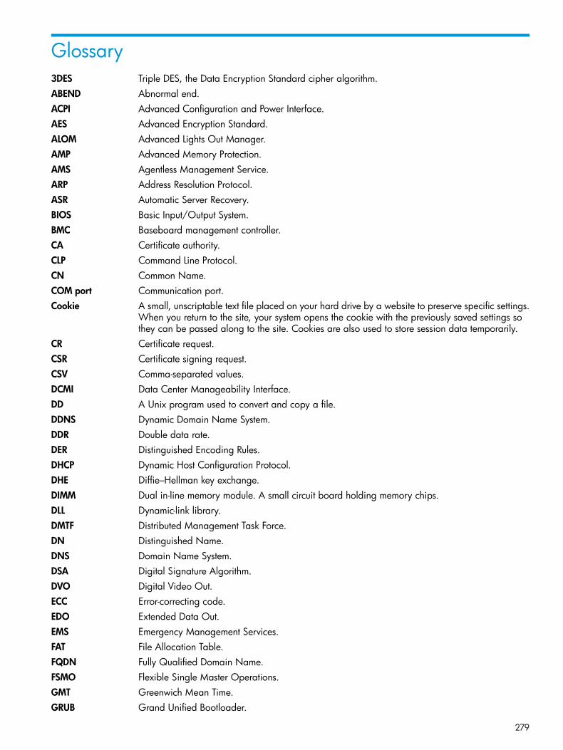
Glossary3DES Triple DES, the Data Encryption Standard cipher algorithm.ABEND Abnormal end.ACPI Advanced Configuration and Power Interface.AES Advanced Encryption Standard.ALOM Advanced Lights Out Manager.AMP Advanced Memory Protection.AMS Agentless Management Service.ARP Address Resolution Protocol.ASR Automatic Server Recovery.BIOS Basic Input/Output System.BMC Baseboard management controller.CA Certificate authority.CLP Command Line Protocol.CN Common Name.COM port Communication port.Cookie A small, unscriptable text file placed on your hard drive by a website to preserve specific settings.
When you return to the site, your system opens the cookie with the previously saved settings sothey can be passed along to the site. Cookies are also used to store session data temporarily.
CR Certificate request.CSR Certificate signing request.CSV Comma-separated values.DCMI Data Center Manageability Interface.DD A Unix program used to convert and copy a file.DDNS Dynamic Domain Name System.DDR Double data rate.DER Distinguished Encoding Rules.DHCP Dynamic Host Configuration Protocol.DHE Diffie–Hellman key exchange.DIMM Dual in-line memory module. A small circuit board holding memory chips.DLL Dynamic-link library.DMTF Distributed Management Task Force.DN Distinguished Name.DNS Domain Name System.DSA Digital Signature Algorithm.DVO Digital Video Out.ECC Error-correcting code.EDO Extended Data Out.EMS Emergency Management Services.FAT File Allocation Table.FQDN Fully Qualified Domain Name.FSMO Flexible Single Master Operations.GMT Greenwich Mean Time.GRUB Grand Unified Bootloader.
279
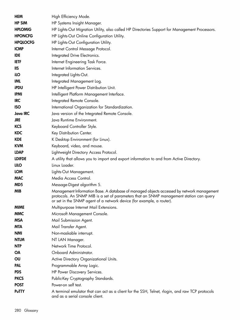
HEM High Efficiency Mode.HP SIM HP Systems Insight Manager.HPLOMIG HP Lights-Out Migration Utility, also called HP Directories Support for Management Processors.HPONCFG HP Lights-Out Online Configuration Utility.HPQLOCFG HP Lights-Out Configuration Utility.ICMP Internet Control Message Protocol.IDE Integrated Drive Electronics.IETF Internet Engineering Task Force.IIS Internet Information Services.iLO Integrated Lights-Out.IML Integrated Management Log.iPDU HP Intelligent Power Distribution Unit.IPMI Intelligent Platform Management Interface.IRC Integrated Remote Console.ISO International Organization for Standardization.Java IRC Java version of the Integrated Remote Console.JRE Java Runtime Environment.KCS Keyboard Controller Style.KDC Key Distribution Center.KDE K Desktop Environment (for Linux).KVM Keyboard, video, and mouse.LDAP Lightweight Directory Access Protocol.LDIFDE A utility that allows you to import and export information to and from Active Directory.LILO Linux Loader.LOM Lights-Out Management.MAC Media Access Control.MD5 Message-Digest algorithm 5.MIB Management Information Base. A database of managed objects accessed by network management
protocols. An SNMP MIB is a set of parameters that an SNMP management station can queryor set in the SNMP agent of a network device (for example, a router).
MIME Multipurpose Internet Mail Extensions.MMC Microsoft Management Console.MSA Mail Submission Agent.MTA Mail Transfer Agent.NMI Non-maskable interrupt.NTLM NT LAN Manager.NTP Network Time Protocol.OA Onboard Administrator.OU Active Directory Organizational Units.PAL Programmable Array Logic.PDS HP Power Discovery Services.PKCS Public-Key Cryptography Standards.POST Power-on self test.PuTTY A terminal emulator that can act as a client for the SSH, Telnet, rlogin, and raw TCP protocols
and as a serial console client.
280 Glossary
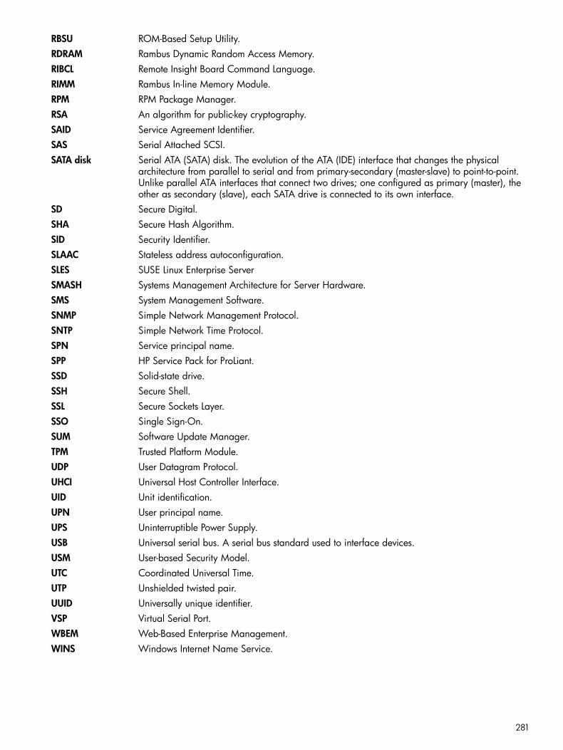
RBSU ROM-Based Setup Utility.RDRAM Rambus Dynamic Random Access Memory.RIBCL Remote Insight Board Command Language.RIMM Rambus In-line Memory Module.RPM RPM Package Manager.RSA An algorithm for public-key cryptography.SAID Service Agreement Identifier.SAS Serial Attached SCSI.SATA disk Serial ATA (SATA) disk. The evolution of the ATA (IDE) interface that changes the physical
architecture from parallel to serial and from primary-secondary (master-slave) to point-to-point.Unlike parallel ATA interfaces that connect two drives; one configured as primary (master), theother as secondary (slave), each SATA drive is connected to its own interface.
SD Secure Digital.SHA Secure Hash Algorithm.SID Security Identifier.SLAAC Stateless address autoconfiguration.SLES SUSE Linux Enterprise ServerSMASH Systems Management Architecture for Server Hardware.SMS System Management Software.SNMP Simple Network Management Protocol.SNTP Simple Network Time Protocol.SPN Service principal name.SPP HP Service Pack for ProLiant.SSD Solid-state drive.SSH Secure Shell.SSL Secure Sockets Layer.SSO Single Sign-On.SUM Software Update Manager.TPM Trusted Platform Module.UDP User Datagram Protocol.UHCI Universal Host Controller Interface.UID Unit identification.UPN User principal name.UPS Uninterruptible Power Supply.USB Universal serial bus. A serial bus standard used to interface devices.USM User-based Security Model.UTC Coordinated Universal Time.UTP Unshielded twisted pair.UUID Universally unique identifier.VSP Virtual Serial Port.WBEM Web-Based Enterprise Management.WINS Windows Internet Name Service.
281

Index
Symbols.NET IRC see Remote Console
Aaccess options
Authentication Failure Logging, 43, 45configuring, 41configuring with iLO RBSU, 43configuring with web interface, 41Idle Connection Timeout, 42iLO Functionality, 42, 44iLO ROM-Based Setup Utility, 42, 44Minimum Password Length, 43Require Login for iLO RBSU, 42, 44Serial Command Line Interface Speed, 42, 44Serial Command Line Interface Status, 42, 44Server FQDN/IP Address, 43Server Name, 43Show iLO IP during POST, 42, 44Virtual Serial Port Log, 43
access settingsaccess options, 41configuring, 39IPMI/DCMI settings, 41service settings, 39
accessing iLOtroubleshooting, 246
Active Directoryautomatic certificate request, 200certificate services, 200directory objects, 209directory services , 207directory services objects, 210installation prerequisites, 207installing, 208integration, 55preparation, 200Snap-in installation and initialization for Active
Directory, 209verifying certificate services, 200
Active Health Systemclearing the log, 142data collection, 101downloading the log, 139, 141overview, 139
active iLO sessionsviewing, 114
AES/3DESconfiguring, 64connecting to iLO, 64overview, 62viewing, 63
Agentless Managementconfiguring, 90overview, 87
Agentless Management Servicecontrol panel, 88, 89, 94downloading, 88guidelines, 88installing, 88Linux, 89Ubuntu, 89verifying installation, 89VMware, 89Windows, 89
AlertMaildisabling, 99enabling, 98overview, 98
alertsAlertMail, 98Remote Syslog, 99SNMP, 93SNMP alert destinations, 90troubleshooting, 248, 249
Authentication Failure Loggingconfiguring, 43using with SSH clients, 45
Authentication PassphraseSNMPv3, 92
Authentication ProtocolSNMPv3, 92
authorized resellerTechnical support, 265
Bblocked ports
troubleshooting, 248brown-out recovery, 177browser support
web interface, 109
Ccertificates see SSL certificatesCLI
access setting, 44authentication, 42serial port speed, 42, 44Virtual Serial Port log, 43
compatibility, directory migration, 229connecting to iLO
troubleshooting, 247, 248Console Capture, 153control panel, 89
Agentless Management Service, 88, 94cookie behavior
troubleshooting, 258
Ddata collection
Active Health System, 101
282 Index

privacy, 101Remote Support, 101system configuration, 101
Dedicated Network Portenabling with iLO RBSU, 81enabling with iLO web interface, 81
DHCPIPv4 settings, 81IPv6 settings, 83
diagnostic toolsusing, 142
Directories Support for ProLiant Management Processors,230configuring directories with HP extended schema, 235Configuring directories with schema-free integration,
239installing, 230naming management processors, 234Selecting a directory access method, 234Setting up management processors for directories, 239updating iLO firmware, 232using, 230
directory groupsadding, 37deleting, 39editing, 37viewing, 35
directory integrationbenefits, 193Kerberos, 194migration, 229overview, 193setting up schema free directories, 200troubleshooting, 245, 249troubleshooting logout, 250troubleshooting user contexts, 250
directory settingsauthentication, 56configuring, 55directory server settings, 56directory test controls, 62Kerberos, 56test results, 60verifying, 58
directory testsresults, 60running, 58test controls, 62
Directory-enabled remote managementconfiguring, 223overview, 223requirements, 223
DNS namedefault value, 21
DNS serversIPv4, 81IPv6, 83
documentationproviding feedback on, 268
domain nameconfiguring, 76
downloadingActive Health System log, 141
drivers see iLO drivers
Ee-Directory
integration, 55eDirectory integration
directory services, 215eDirectory Lights-Out Management, 222prerequisites, 215Snap-in installation and initialization for eDirectory, 215
Emergency Management ServicesWindows EMS Console, 161
enclosurefan control, 187temperature, 187
encryptionAES/3DES, 62configuring, 64, 65connecting to iLO, 64FIPS Mode, 62overview, 62viewing, 63
evaluation license, 32event log
clearing, 135overview, 133saving, 135troubleshooting, 242viewing, 133
Ffans
iLO Virtual Fan, 187viewing, 115
features, 13FIPS Mode
disabling, 65enabling, 64overview, 62viewing, 63
Firefoxtroubleshooting with Remote Console, 250
firmware, 25see also iLO firmwareviewing installed firmware, 132
FQDNconfiguring, 43
Ggateway IP address
IPv4, 81Global iLO 4 Settings see access optionsgraceful shutdown
power, 177
283

Hhardware and software links
troubleshooting, 244health status
viewing, 113health summary
viewing, 114hostname
configuring, 76hot keys
Remote Console, 155HP Insight Control software
integration, 189HP schema directory integration
configuring, 203overview, 203requirements, 204
HP Zero Sign InKerberos, 197, 199
HPLOMIG see Directories Support for ProLiantManagement Processors
IIdle Connection Timeout
configuring, 42iLO
configuring, 25iLO controls
web interface, 111iLO Dedicated Network Port see network
link state, 81iLO drivers
downloading, 22installing, 22Linux, 23VMware, 24Windows, 23
iLO firmwaredownloading, 26offline update, 26online update, 25
in-band update, 25out-of-band update, 26
troubleshooting firmware updates, 260updating, 25, 27, 232
iLO Functionalityconfiguring, 42, 44
iLO Mobile applicationoverview, 14
iLO RBSU, 262access setting, 42, 44configuring access options, 43configuring local user accounts, 44configuring user accounts, 20enabling the Dedicated Network Port, 81enabling the Shared Network Port, 79Global iLO 4 Settings, 44login requirement, 42, 44network settings, 19
overview, 14security, 47setting up iLO, 18troubleshooting, 246
iLO Security Override Switch see Security Override SwitchiLO Shared Network Port see networkiLO web interface see web interfaceInsight Management Agents
downloading, 88installing, 88integration, 97overview, 87using, 146
Insight Onlineserver identification, 257
Insight RSserver identification, 257
Integrated Management Log, 138clearing, 139maintenance note, 138overview, 136saving, 138viewing, 136
integrationSystems Insight Manager, 190
IP addressconfiguring, 43configuring a static IP address, 19IP address and subnet mask restrictions, 227IPv4, 81IPv6, 83viewing during POST, 42, 44
IPMI/DCMIconfiguring, 41server management, 188user privileges, 37
IPv4, 73see also networkconfiguring, 81DHCP, 81DNS servers, 81gateway address, 81IP address, 81ping gateway on startup, 81static routes, 81subnet mask, 81, 83WINS servers, 81
IPv6, 73see also networkconfiguring, 83DHCP, 83DNS servers, 83gateway address, 83static routes, 83
JJava IRC see Remote Console
284 Index

KKerberos, 55
computer accounts, 194configuring, 196configuring with CLI, 197configuring with iLO scripts, 197directory integration, 194generating a keytab, 195HP Zero Sign In, 197, 199iLO configuration, 196login by name, 199realm names, 194single sign-on, 197, 199time requirement, 197two-factor authentication, 194user accounts, 195user groups, 196
kernel debuggingtroubleshooting, 241
keyboardconfiguring persistent mouse and keyboard, 185
Llanguage packs, 111
configuring the current language, 31configuring the default language, 31installing, 29overview, 28selecting, 30uninstalling, 31
licensingevaluation license, 32installation, 33license types, 32options, 269troubleshooting, 249viewing in Systems Insight Manager, 192
LinuxAgentless Management Service, 89configuring the Virtual Serial Port, 160iLO drivers, 23Text-based Remote Console, 163
login, 109authentication failure, 43default user account, 21security, 49security banner, 71troubleshooting, 245, 246, 247, 248unknown authority message, 110
logsiLO Event Log, 133Remote Syslog, 99Virtual Serial Port, 43
Mmaintenance note
Integrated Management Log, 138memory information
viewing, 125
Microsoft ClickOncerequirement, 71
Microsoft softwaredirectory services for Active Directory, 207
migration utilities, 229Minimum Password Length
configuring, 43mobile application
overview, 14mouse
configuring persistent mouse and keyboard, 185
Nnetwork, 76
configuration summary, 73configuring, 76configuring a VLAN, 80configuring IPv4 settings, 81configuring IPv6 settings, 83configuring NIC settings, 76connecting iLO, 18enabling the Dedicated Network Port with iLO RBSU,
81enabling the Dedicated Network Port with iLO web
interface, 81enabling the Shared Network Port with iLO RBSU, 79enabling the Shared Network Port with iLO web
interface, 80IPv4 summary, 73IPv6 Summary, 73link state, 76, 81name service limitations, 76namespace issues, 76Shared Network Port, 78SNTP, 86troubleshooting, 247, 248
network failed flash recovery, 260NIC information
viewing, 128NIC settings
configuring, 76
OOnboard Administrator
iLO option, 187using with iLO, 185
overview page, 111
Ppassword
minimum length, 43security, 46
ping gateway on startupIPv4, 81
port matchingSystems Insight Manager, 191
ports, 248IPMI/DCMI, 41SSH, 39
285

Systems Insight Manager, 191power
brown-out recovery, 177configuring persistent mouse and keyboard, 185configuring threshold alerts, 184Dynamic Power Capping for server blades, 187efficiency, 177graceful shutdown, 177iLO power management, 177managing server power, 178overview, 176power capping, 184Power Regulator for ProLiant, 182server, 176system power restore setting, 179usage, 180viewing the current power state, 181viewing the server power history, 182
power cappingconfiguring, 184
power informationviewing, 119
Power Regulator for ProLiantconfiguring, 182Dynamic Power Capping for server blades, 187
power settingsconfiguring, 182
power switchRemote Console, 151
Privacy PassphraseSNMPv3, 92
Privacy ProtocolSNMPv3, 92
processor informationviewing, 124
proxy serverusing with iLO, 248
RRBSU, 14
see also iLO RBSURemote Console
.NET IRC requirements, 147acquiring, 150computer lock settings, 69configuring trust settings (.NET IRC), 71Console Capture, 153creating hot keys, 155idle connection timeout, 42Inactive .NET IRC, 253Java IRC requirements, 148port, 39power switch, 151sharing, 152starting, 149text-based, 156troubleshooting, 247, 250using .NET IRC and Java IRC, 146using Virtual Media, 152
Remote Console Portconfiguring, 39
remote management toolstarting, 111, 189viewing, 189
Remote Supportdata collection, 101overview, 100prerequisites, 102registering, 102service events, 101system configuration, 101
Remote Syslogconfiguring, 99disabling, 100enabling, 99
Require Login for iLO RBSUconfiguring, 42, 44
requirementsHP schema directory integration, 204Virtual Media, 165
Reset to Factory Defaults, 262resetting to defaults, 262restoring, 262
factory presets, 262
Sschema documentation, 273
Core attribute definitions, 274hpqPolicyDN, 274hpqRoleIPRestrictionDefault, 275hpqRoleIPRestrictions, 275hpqRoleMembership, 274hpqRoleTimeRestriction, 276hpqTargetMembership, 275
Core attributes, 273Core class definitions, 273
hpqPolicy, 274hpqRole, 274hpqTarget, 273
Core classes, 273Lights-Out Management attributes, LDAP, 276, 277
hpqLOMRightConfigureSettings, 278hpqLOMRightLocalUserAdmin, 278hpqLOMRightLogin, 277hpqLOMRightRemoteConsole, 277hpqLOMRightServerReset, 277hpqLOMRightVirtualMedia, 277
Lights-Out Management classes, LDAP, 276hpqLOMv100, 276
Lights-Out Management specific LDAP OID classes andattributes, 276
Schema Extenderinstaller, 205
schema free directoriesconfiguration options, 202configuring, 201nested groups, 202setting up, 200
286 Index

scripting and command lineoverview, 15
Secure Shell (SSH) Accessconfiguring, 39
Secure Shell (SSH) Portconfiguring, 39
securityconfiguring, 46guidelines, 46iLO RBSU, 47login, 49login security banner, 71passwords, 46Remote Console computer lock, 69TPM support, 49user account privileges, 49user accounts, 49
Security NameSNMPv3, 92
Security Override Switch, 42emergency access, 249overview, 48
Serial Command Line Interface Speedconfiguring, 42, 44
Serial Command Line Interface Statusconfiguring, 42, 44
serial number/iLO information pull tab, 21server
configuring FQDN/IP Address, 43configuring Server Name, 43managing power, 178managing with IPMI, 188powering on, 176
server firmwaredownloading, 27
Server FQDN/IP Addressconfiguring, 43
Server Nameclearing, 262configuring, 43
service eventsRemote Support, 101
service settings, 39Remote Console Port, 39Secure Shell (SSH) Access, 39Secure Shell (SSH) Port, 39SNMP Access, 39SNMP Port, 39SNMP Trap Port, 39Virtual Media Port, 39Web Server Non-SSL Port, 39Web Server SSL Port, 39
setting up iLOnetwork connection, 18overview, 16preparation, 16static IP address, 19user accounts, 20, 49using iLO RBSU, 18
web interface, 21Shared Network Port
enabling with iLO RBSU, 79enabling with iLO web interface, 80FlexibleLOM, 76LOM, 76overview, 78
Show iLO IP during POSTconfiguring, 42, 44
single sign-onconfiguring, 65, 66Kerberos, 197, 199privileges, 66removing trusted certificates, 69trust mode, 66trusted certificates, 67viewing trusted certificates, 68
SNMP, 93see also SNMP alertsaccess, 39configuring, 90configuring alerts, 93, 94configuring SNMPv3 users, 92overview, 87ports, 39Receiving alerts in Systems Insight Manager, 191trap definitions, 95
SNMP Accessconfiguring, 39
SNMP alertsCold Start Trap Broadcast, 93Forward Insight Manager Agent SNMP Alerts, 93iLO SNMP Alerts, 93sending test alerts, 93SNMPv1 Traps, 93Trap Source Identifier, 93
SNMP Pass-thruconfiguring, 90
SNMP Portconfiguring, 39
SNMP Trap Portconfiguring, 39
SNMPv3Authentication Passphrase, 92Authentication Protocol, 92configuring the engine ID, 93Privacy Passphrase, 92Privacy Protocol, 92Security Name, 92
SNTPconfiguring, 86
SSHauthentication failure logging, 45authorizing keys, 51, 52authorizing keys from Systems Insight Manager, 52configuring access, 39deleting keys, 52key administration, 50key requirements, 50
287

port, 39troubleshooting, 256
SSLcertificates, 52, 110importing certificates, 53obtaining certificates, 53troubleshooting, 261troubleshooting certificates, 248viewing certificates, 53
SSL Bio Error during registrationtroubleshooting, 257
SSOconfiguring with Systems Insight Manager, 190
static routesIPv4, 81IPv6, 83
status informationviewing, 113
storage informationviewing, 129
subnet maskIPv4, 81
supportTechnical support, 265
system informationviewing, 111, 114
System Management Homepage, 97Systems Insight Manager
authorizing SSH keys, 52configuring single sign-on, 190iLO identification, 190iLO license, 192iLO links, 191integrating with iLO, 190overview, 190port matching, 191single sign-on, 68SNMP alerts, 191troubleshooting, 249viewing iLO, 191viewing iLO status, 190
Ttechnical support
Technical support, 265telephone numbers
Technical support, 265temperature information
viewing, 117Text-based Remote Console, 163
customizing, 162Linux sessions, 163overview, 156Textcons, 161troubleshooting, 256
Textcons see Text-based Remote Consoletime zone
SNTP, 86TPM
using, 49traps
troubleshooting, 248troubleshooting, 241
alerts and traps, 248blocked ports, 248certificate error, 263cookies, 258directory integration, 245, 250directory logout, 250event log, 242hardware and software links, 244iLO access, 246iLO firmware update, 260iLO RBSU, 246Inactive .NET IRC, 253IRC failed to connect to server error message, 254kernel debugging, 241ktpass utility, 250license, 249login, 245, 246, 247, 248login credentials, 245network failed flash recovery, 260Remote Console, 247, 250Security Override Switch, 249server identification, 257SNMP and Systems Insight Manager, 260SSH, 256SSL Bio Error, 257Systems Insight Manager alarms, 249testing SSL, 261text-based Remote Console, 256unable to connect to iLO, 247, 248Virtual Media, 247, 254, 256
trust settingsRemote Console, 71
two-factor authenticationKerberos, 194
UUbuntu
Agentless Management Service, 89unknown authority message
logging in to iLO, 110user accounts
adding, 20, 35default user account, 21deleting, 39directory authentication, 55editing, 35enabling local accounts, 44, 56IPMI/DCMI, 37overview, 33privileges, 33, 49security, 49viewing, 34
user rolesIP address and subnet mask restrictions, 227
User-based Security Model
288 Index

SNMPv3, 92
Vvirtual fan, 187Virtual Media
IIS, scripted media, 172OS information, 165overview, 163port, 39scripting, IIS requirements, 172troubleshooting, 247, 254, 256using from web interface, 167using with Remote Console, 152
Virtual Media Portconfiguring, 39
Virtual Serial PortLinux configuration, 160overview, 157Windows configuration, 161
Virtual Serial Port Logconfiguring, 43
VLANconfiguring, 80
VMwareAgentless Management Service, 89iLO drivers, 24
Wweb interface
browser support, 109enabling the Dedicated Network Port, 81enabling the Shared Network Port, 80idle connection timeout, 42iLO controls, 111overview, 14using, 109
Web Server Non-SSL Portconfiguring, 39port, 39
Web Server SSLport, 39
Web Server SSL Portconfiguring, 39
WindowsAgentless Management Service, 89enabling EMS Console, 161iLO drivers, 23
WINS serversIPv4, 81
289