
HP Archive · I. : HP Archive .. . This vintage Hewlett Packard document was preserved and...
19
I. : HP Archive .. . This vintage Hewlett Packard document was preserved and distributed by www. hparchive.com ' Please visit us on the web ! .. On-line curator: Tony Gerbic
Transcript of HP Archive · I. : HP Archive .. . This vintage Hewlett Packard document was preserved and...

I . : HP Archive
.. .
This vintage Hewlett Packard document was preserved and distributed by
www. hparchive.com
' Please visit us on the web ! . .
On-line curator: Tony Gerbic

O P E R A T I N G A N D S E R V I C E M A N U A L
MODEL 2 9 7 A SERIALS PREFIXED: 139 -
SWEEP DRIVE
1961 Copyrieht H E W L E T T - P A C K A R D COMCANV 1501 PAGE M I L L ROAD, P A L 0 ALTO, C A L I F O R N I A . U.S.A.
01163-2

Model 297A Table of Contents Lis ts of Illustrations and Tables
TABLE OF CONTENTS
Section I GENERAL INFORMATION . . . . . . . .
1.1 . General Description . . . . . . . . 1.3 . Uses . . . . . . . . . . . . . . . . . 1.5 . Instrument Identification . . . . . . 1.7 . Power Cable . . . . . . . . . . . .
11 INSTALLATION . . . . . . . . . . . . . . 2.1 . General Information . . . . . . . . 2.3 . Mechanical Inspection . . . . . . . 2.5 . Mounting . . . . . . . . . . . . . . 2.6 .
Analyzer . . . . . . . . . . . . . 2.8 . Mounting on the Bench Stand . . . 2- 10 . Power Requirements . . . . . . . . 2.12 . In-Cabinet Performance Check . . . 2- 14 . Reshipment . . . . . . . . . . . . .
111 OPERATION . . . . . . . . . . . . . . . . 3- 1 . General Information . . . . . . . . 3.3 . Operating Controls . . . . . . . . . 3.5 . Sweep Sector Operation . . . . . . . 3.6 . 3.8 .
Mounting on the 302A Wave
Sweep Sector Operation with Model 302A . . . . . . . . . . . . Sweep Sector Operation with De- vices other than the Model 302A .
3.10 . Sweep Voltage Output . . . . . . . .
Page Section Page
1-1 IV PRINCIPLES OF OPERATION . . . . . . . 4-1 1-1 4.1 . Introduction . . . . . . . . . . . . . 4-1 1-1 4.3 . Power Supply . . . . . . . . . . . . 4-1 1-1 4.5 . Motor . . . . . . . . . . . . . . . . . 4-1 1-1
2-1 v 2- 1 2- 1 2- 1
2-1 2- 1 2-2 2-2 2-2
3- 1 3- 1 3- 1 3- 1
MAINTENANCE . . . . . . . . . . . . . . 5-1 5.1 . Introduction . . . . . . . . . . . . . 5-1 5.3 . Cabinet Removal . . . . . . . . . . . 5-1 5.5 . Lubrication . . . . . . . . . . . . . 5-1 5.7 . Test Equipment . . . . . . . . . . . . 5-1 5.9 . Troubleshooting . . . . . . . . . . . 5-1 5.10 . Power Supply . . . . . . . . . . . 5-1 5.12 . Gear Trains . . . . . . . . . . . . 5-1 5.14 . Motor and Gear Replacement . . . . 5.15 . Motor Replacement . . . . . . . . 5-2 5- 17 . Gear Replacement 5-2 5.18 . In-Cabinet Performance Check . . . 5.20 . RPM Check . . . . . . . . . . . . 5-2 5.22 . Torque Check . . . . . . . . . . . 5-2 5.24 . Power Supply Check . . . . . . . . 5-2
5-2
. . . . . . . . . 5-2
3- 1 VI REPLACEABLEPARTS . . . . . . . . . . 6-1 .
3- 1 6.1 . Introduction . . . . . . . . . . . . . 6-1 3- 1 6.4 . Ordering Information . . . . . . . . 6-1
LIST OF ILLUSTRATIONS
Number Title
1.1 . Model 297A Sweep Drive . . . . . . . . . . . 2.1 . Model 297A Mounted on 302A . . . . . . . . 2.2 . Assembled Bench Stand . . . . . . . . . . . 2.3 . Model 297A Mounted on Bench Stand . . . . 3- 1 . Operating Controls 5.1 Schematic Diagram 6.1 . Exploded View. Model 297A . . . . . . . . .
. . . . . . . . . . . . . . . . . . . . . . . . . . . . .
LIST OF TABLES
Page
1-0 2-0 2- 1 2-2 3-2 5-3 6-4
Number Title Page
1.1 . Specifications . . . . . . . . . . . . . . . . . 1-1 5.1 . Tes t Equipment . . . . . . . . . . . . . . . . 5-1 6.1 . Replaceable Parts. Electrical . . . . . . . . 6-1 6.2 . Replaceable Parts. Mechanical . . . . . . . 6-3
01163-1

Section I Figure 1-1
1-0
Figure 1-1. Model 297A Sweep Drive
Model 297A
01163-1

I ’-
Model 297A
S E C T I O N I GENERAL I N F O R M A T I O N
Section I Paragraphs 1-1 to 1-9
1-1. GENERAL DESCRIPTION. 1-2. The Model 297A, formerly called the Model AC-97C, is a two-speed motor driven unit designed to sweep oscillators and other tunable devices through their ranges automatically. The Model 297A reverses automatically when i t reaches a preset clockwise or counterclockwise limit. The limits can be se t for a very narrow or broad range. The Model 297A has two speeds: HIGH SPEED gives an output shaft rota- tion of 10 rpm, LOW SPEED gives an output shaft speed of 1.0 rpm. An output voltage, useful for driving x-y recorders, oscilloscopes, or other de- vices, is supplied to output terminals. The output voltage is proportional to output shaft rotation. Figure 1-1 illustrates the Model 297A, with brackets for mounting on the Model 302A.
1-3. USES. 1-4. The Model 297A was designed primarily for use with the @ Model 302A Wave Analyzer andis supplied with necessary hardware to mount on the Model 302A. The Model 297A can be used with other devices that do not require excessive torque. For applications other than with the Model 302A, the Model 297Ais available with a bench stand. When the benchstand is used; the Model 297A can be adjusted between 4 and 12 inches in
height. The Model 297A is supplied with two flexible couplers so that it may be used with either ($9 Model 302A o r 31QA.
1-5. INSTRUMENT I D E N T I F I C A T I O N . 1-6. Hewlett-Packard uses a two-section eight-digit ser ia l number (000-00000). If- the first three digits of the serial number on your instrument do not agree with those on the title. page of this manual, change sheets supplied with the manual will define differences between your instrument and the Model 297A described in this manual.
1-7. P O W E R CABLE. 1-8. For the protection of operating personnel, the National Electrical Manufacturers’ Association (NEMA) recommends that the instrument panel and cabinet be grounded. This instrument is equipped with a three-conductor power cable which, when plugged into an appropriate receptacle, grounds the instrument. The offset pin on the power cable three-prong connector is the ground pin.
1-9. To preserve the protection feature when opera- ting the instrument from a two-contact outlet, use a three-prong to two-prong adapter and connect the green pigtail on the adapter to ground.
Table 1-1. Specifications
SWEEP RANGE: 64 revolutions (see Sweep Voltage Output specifications).
SWEEP LIMITS: Any interval from 64 revolutions to 10 degrees.
SWEEP SPEED WITH @ 302A: 170 cps persecond and 17 cps per second.
SHAFT SPEED: 10 rpm, 1 rpm, and neutra1;quick change speed transfer without stopping. Neutral permits manual operation.
STARTING AND RUNNING TORQUE: 9 oz-in a t 10 rpm. Friction clutch limits torque a t 1 rpm to approximately 12 oz-in.
MOTOR: Reversible synchronous capacitor type reluctance motor; may be stalled indefinitely.
OUTPUT SHAFT: 1/4 inch diameter with 7/16 coupler inch for ($9 Model 302A.
POWER: 115 volts lo%, 50 to 60 cps, 12 watts, running or stalled.
SWEEP OUTPUT: 15 volts maximum. Change of MOUNT: Mounts on front panel of ($9 Model 302A. output proportional to change in shaft position and zero output may be set for any shaft posi- DIMENSIONS:’ 3-1/2 inches high, 7 inches wide, tion. Full output may be obtained with either 5-1/4 inches deep, shaft extends 13/16 inch 2.1 revolutions or with 50 revolutions of the behind case. output shaft. When shaft speed control is in High Speed, sweep output control cannot be set ACCESSORIES AVAILABLE: Bench stand(ll505A) to Short Sweep. Adjust shaft height from 4 to 12 inches.
01163-2 1-1

Section I1 Figure 2-1
2-0
Model 297A
T
Figure 2-1. Model 297A Mounted on 302A
. -
01163-1

Model 297A Section I1 Paragraphs 2-1 to 2-9
SECTION II
INSTALLATION
2-1. GENERAL I N F O R M A T I O N . 2-2. The Model297Ais shipped from the factory with two flexible couplers. One is suitable for connecting the 297A to the 302A; it has a 1/4-inch adapter on one end anda7/16-inch adapter on the other end. The other is suitable for connecting the 297A to the 310A; it has a 1/4-inch adapter on both ends.
2-3. MECHANICAL INSPECTION. 2-4. Unpack the instrument upon receipt and inspect it for signs of physical damage such as scratched panel surfaces, broken knobs, etc. If there is any apparent damage, file a claim with the carrier and refer to the warranty page in this manual.
2-5. M O U N T I N G .
2-6. MOUNTING ON THE 302A WAVE ANALYZER. . 2-7. To mount the Model 297A on the Model 302A,
proceed a s follows: a. Remove the fine vernier knob on theModel302A.
b. Set the Model 302A on its back so controls a r e
c. Counting from right to left on the 302A, remove second and third screws nearest the top of the 302A. These screws will be the twonearest the FREQUENCY dial (see figure 2-1).
d. Carefully slide the 297A output shaft coupler over the 302A vernier drive shaft. Tighten the output shaft coupler screws.
e. Align holes in the two mounting lugs with holes made by removal of two screws on the Model 302A.
f. Carefully insert screws in holes of mounting lugs and finger tighten. Be careful. There may be three shims under each screw-hole of the Model 302A. If jarred, they may fall into themechanism. Be su re the output shaft rotates freely before tightening the screws.
, facing upwards.
2-8. MOUNTING ON THE BENCH STAND. 2-9. To mount the Model 297A on the 11505A bench stand, proceed as follows:
a. Remove the four screws at the r ea r that secure the mounting bars to the back of the Model 297A.
b. Attach the two bench stand brackets to the back of the Model 297A, using the four extra screws sup- plied with the bench stand.
c. Insert the two rods supplied with the benchstand into the holes in the stand. Tighten the screws at the r e a r of the stand to secure the rods (see figure 2-2).
d. Slide the Model 297A mounting brackets over and down on the rods (see figure 2-3). Adjust the Model 297A to the proper height (make sure the output shaft
-
01163-2
rotates freely when coupled to the instrument to be driven), then tighten the screws on the mounting bars to hold the Model 297A in place.
Note
The 297A drive shaft has a bushing -band friction clutch: care is required in mounting the flexible coupler on the 297A drive shaft to ensure that the friction clutchperformsprop- erly. The appropriate coupler should be mounted as follows:
a. Place coupler on shaft and align one of setscrews with openingin steel band on shaft and tighten aligned setscrew moderately.
b. Tighten other setscrews.
CAUTION: When mounting flexible clutch on @ Model 310A shaft, setscrews must be flat- rather than cup-ended.
c . Torque required for slippage in friction clutch should be approximately 20 inch- ounces. Readjustment of aligned setscrew may be necessary
f , 1 ; I ' i
' I
i
!
Figure 2-2. Assembled 11505A Bench Stand
2-1

Model 297A Section I1 Paragraphs 2-10 to 2-15
2-10. POWER REQUIREMENTS.
2- 11. The Model 297A operates from a 50- to 60-cycle, 115-volt power source. If 230-volt operation is de- sired, a suitable 230- to 115-volt step-down trans- former, such as the @ 9100-0007 can be used.
2-12 . I N - C A B I N E T P E R F O R M A N C E CHECK. 2-13. If an in-cabinet performance check is desired, refer to section V of this manual.
2-14 . RESHIPMENT. 2- 15. To protect electronic equipment during storage o r shipment, always use the best packaging methods available. Contract packaging companies in many cities can provide dependable packing on short notice. The following packaging methods a r e recommended:
a. Original. Place instrument i n original container. Replace all packing pads and fillers in theexact posi- tion they originally occupied.
b. Rubberized Hair. Cover painted surfaces of instrument with protective wrapping paper. Pack instrument securely in strong corrugated container (350 lb/square inch bursting test) with 2-inch rubber- ized hair pads placed along all surfaces of the instru- ment. Insert filler between pads and container to insure a snug f i t on all surfaces of the instrument.
c. Excelsior. Cover painted surfaces with protec- tive wrapping paper. Pack instrument in a strong corrugated container (350 lb/square inch bursting test) with a layer of excelsior about 6 inches thick, packed firmly against all surfaces of the instrument.
i
7
Figure 2-3. Model 297AMounted on 11505A Bench Stand
2-2
-
01 163- 2

Model 297A
SECTION 111
OPERATION
Section I11 Paragraphs 3- 1 to 3- 13
Note 3-1. GENERAL I N F O R M A T I O N . 3-2. The Model 297A supplies power for driving such instruments a s signal generators, potentiometers, and other devices to give a constant change or frequency, resistance, or some other parameter. The rate and amount of change can be controlled toclose tolerances with the panel controls. An output voltage proportional to the amount of rotation is supplied to output ter- minals. The output voltage can be connected to any kind of indicating device having a relatively high input impedance. The remainder of section 111 fully de- scribes the operation of the Model 297A.
3-3. O P E R A T I N G CONTROLS.
3-4. For a description of the operating controls, re- fer to figure 3-1.
3-5. SWEEP SECTOR O P E R A T I O N .
3-6. SWEEP SECTOR OPERATION WITH MODEL 302A.
3-7. To set the Model 297A for sweep sector opera- tion with a Model 302A, proceed a s follows:
a. Set all switches of the Model 297A to the OFF position.
b. Set the speed-change lever at the left side of the Model 297A to NEUTRAL and pull the CW LIMIT and CCW LIMIT knobs to the disengaged position.
Note A s the Model 302A (CPS) FINE control is rotated in a clockwise direction, dial fre- quency decreases.
c. Using the Manual Sweep knob on the 297A, ro- tate the frequency dial in a clockwise direction until the desired lower frequency limit is reached. Then rotate the CW LIMIT knob in a clockwise position un- til i t reaches the mechanical stop. Then push the CW LIMIT knob “in” to the engaged position.
d. Using the Manual Sweep knob, rotate the output shaft counterclockwise until the desired upper fre- quency limit is reached.
e. Rotate the CCW LIMIT knob in a counterclock- wise direction until i t reaches the mechanical stop.
f. Push the CCW LIMIT knob “in” to the engaged position.
g. Set the speed-change lever at the left side to LOW SPEED, and the POWER switch to ON.
When using the Model 297A with the Model 302A, the speed changer must be set to LOW SPEED. The Model 302A has verynarrow pass-band, and if the dial frequency is rapidly changed, the output circuits wil l not respond to changes.
h. Set both the CW and CCW switches to the SWEEP position. The Model 297A will continuously rotate the frequency dial from the lower to upper frequency position.
i. If only a clockwise sweep is desired, s e t the CCW switch to the OFF position. If a counterclock- wise sweep is desired, set the CW SWEEP switch to the OFF position, CCW switch to ON position.
j. Setting the speed-change lever to LOW SPEED will cause the output shaft to rotate a t 1.0 rpm. HIGH SPEED causes the output shaft to rotate at 10 rpm.
3-8. SWEEP SECTOR OPERATION WITH DEVICES OTHER THAN THE MODEL 302A.
3-9. Sweep operation of other devices is similar to operation with the 302A, but the bench stand must be used. When the bench stand is used, be su re the out- put shaft rotates freely when the Model 297A is con- nected to the device. The sector to be swept is set the same a s when the Model 297A is used with the 302A.
3-10. SWEEP V O L T A G E O U T P U T . 3-11. The sweep voltage output can be used to drive recorders, oscilloscopes, and other devices used to define coordinates of a point. The OUTPUT LEVEL control sets the voltage to any level between 0 and 15 volts. This adjustment allows the operator to estab- lish a reference level or zero a recorder. The adjust- ment is made by holding firm the Manual Sweep (center knob) and rotating the OUTPUT LEVEL control.
3-12. When rotating the OUTPUT LEVEL knob in either direction and the potentiometer limits a r e reached, the knob will continue to turn, but the poten- tiometer wiper wil l stop because the knob is connected to the potentiometer through a slip clutch.
3-13. Maximum output impedance is 25K ohms. This will decrease as OUTPUT LEVEL is varied. To ob- tain best linearity, use highest load impedance prac- tical. For example, a load impedance of 2.5 megohms with OUTPUT LEVEL set to mid-position would give a tracking e r r o r of approximately 1.0%.
01163-2 3- 1

Section 111 Model 297A Figure 3-1
T ? ? ? -.
1. POWER ON applies power to the 297A.
2. CW SWEEP allows clockwise sweep.
3. CCW SWEEP allows counterclockwise sweep.
4. CW LIMIT limits amount of clockwise rotation of the output shaft.
5. CCW LIMIT limits amount of counterclockwise rotation of the output shaft.
6. Manual Sweep permits manual rotation of output shaft (speed changer in NEUTRAL).
7. Speed Changer: Permits output shaft rotation of 10 rpm when in HIGH SPEED, output shaft rotation of 1 rpm in LOW SPEED.
,
MP-S-964
/ .:..** ..-+-a .,..:*l ._ _I..
. _..-.:
8. Potentiometer Speed Changer: Uses the full range of the OUTPUT LEVEL PO- tentiometer for 50 rotations of the output shaft when in FULL SWEEP. SHORT SWEEP gives a much larger change of sweep voltage for a given output shaft rotation. Potentiometer Speed Changer cannot be set to SHORT SWEEP when Speed Changer (7) is in HIGH SPEED.
9. SWEEP OUTPUT provides the sweep output voltage for use with a recorder or other instru- ment.
10. OUTPUT LEVEL adjusts the output voltage to any value between 0 and 15 volts for any output shaft position. Allows the operator to set a reference level.
Figure 3-1. Operating Controls
3-2 01163-1

Model 297A
Use
check shaft rotation
voltage and resistance measurements
SECTION I V
Instrument Recommended
@ 410B and @ 400D
PRINCIPLES OF O P E R A T I O N
Section IV and V Paragraphs 4-1 to 5-13
4-1. I N T R O D U CTl 0 N 4-2. Section IV contains informatioa relating to the theory of operation for theModel297A. Al l references will be to the schematic diagram in figure 5-1.
4-3. P O W E R SUPPLY.
4-4. The power supply consists of transformer T1, diodes CR1 and CR2, filter C1, R2 and R3, and CR3. The output of T1 is rectified by CR1 and CR2, then filtered by C1 and applied to breakdown diode CR3. The sweep-voltage potentiometer R3 is connected directly across CR3. The voltage drop across CR2 is 15 volts and is constant because of the breakdown
characteristics of the diode. This supplies the SWEEP OUTPUT potentiometer with a constant 15 volts.
4-5. MOTOR. 4-6. Motor B1 is a reversible synchronous capacitor- type motor. It uses a capacitor to obtain a phase- shifted voltage to give a rotating magnetic field. The motor is reversed by changing the position of micro- switch S4. This causes the current in one-half of the stator winding to either .lead or lag the current in the other half of the stator winding. Themicroswitch de- termines the side of the stator winding that has the leading or lagging current, which in turn determines the motor rotation.
SECTION V M A I N T E N A N C E
5-1. I N T R O D U C T I 0 Ne 5-2. Section V contains information relating to lubri- cation, mechanical parts replacement, and an in- cabinet performance check.
5-3. CABINET R E M O V A L .
5-4. To remove the cabinet, proceed a s follows:
a. Remove the Model 297A from the Model 302A o r other driven device.
b. Remove the screws at the corners (screws sec- uring the mounting bars to the r e a r of the Model 297A).
c. Unloosen the allen screws securing the output shaft coupler, then slide off the output shaft coupler.
d. Lift off the cabinet.
5-5. L U B R I C A T I O N . 5-6. Lubrication is required only between bearings and rotating shafts. Do not lubricate the gear teeth.
Instrument Type I Stop watch
Vacuum Tube Voltmeter
Torque screwdriver with 1/4 in. insert
I
Lubricate the be rings annually with one drop each of light machine oil.
5-7. TEST EQUIPMENT.
5-8. The test equipment o r its equivalent listed in table 5-1 is recommended for an in-cabinet perform- ance check and troubleshooting of the Model 297A.
5-9. TROUBLESHOOTING.
5-10. POWER SUPPLY. 5-11. Troubles in the power supply can be found by using the vacuum tube voltmeter listed in table 5-1, and making voltage and resistance measurements. The dc voltage at the SWEEP OUTPUT terminals should be 15 1 volt with the OUTPUT LEVEL control fully counterclockwise. Maximum ripple present should not exceed 10 mv.
5-12. GEAR TRAINS.
5-13. Troubles in the gear trains can be found by studying gear action, then referring to the exploded
Table 5-1. Test Equipment
Required Characteristics
0-2 min, 1 sec divisions
0-15 vdc 0-10 mv ac
0-9 oz-in. check torque @ 8730-0012 and 8830-0013 I I
4- 5- 01163-1

Section V Paragraphs 5-14 to 5-25
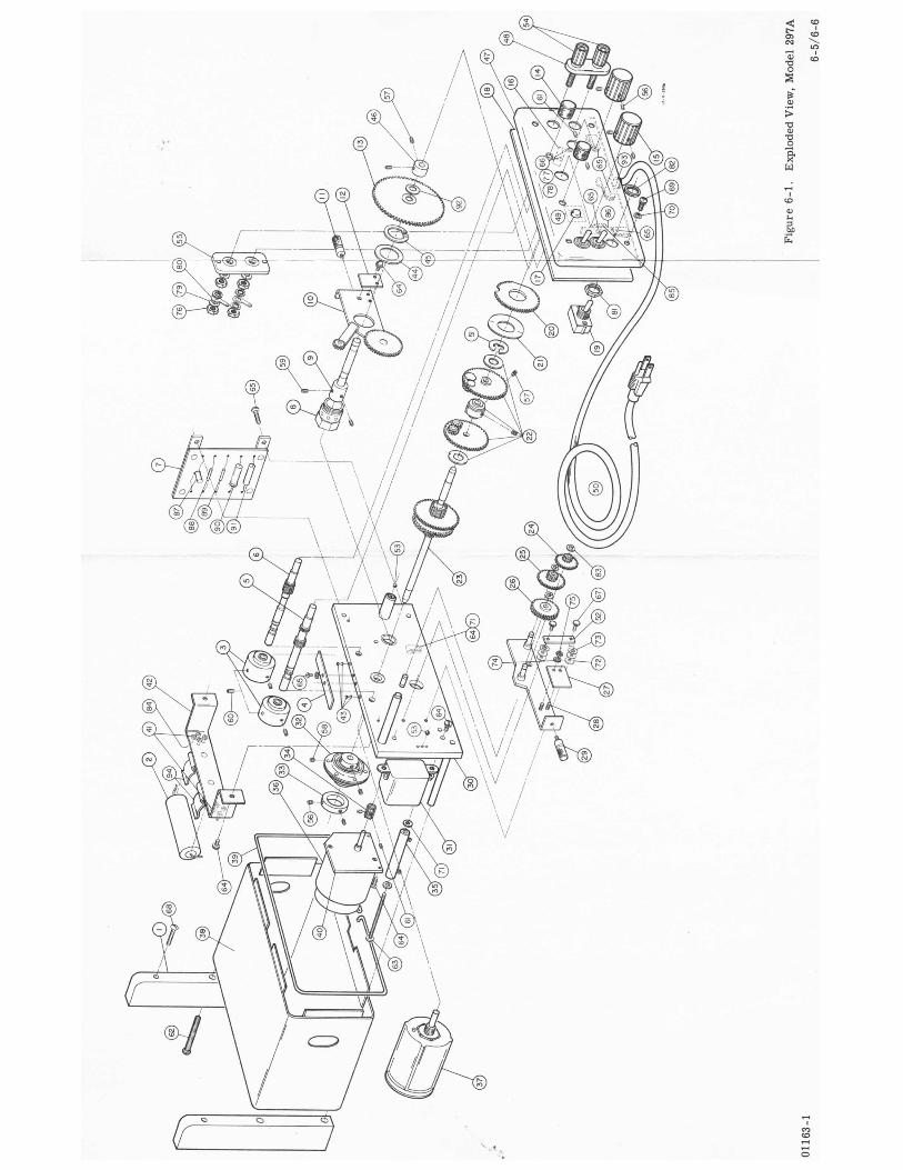
view in figure 6-1. Gears that show excessive wear should be replaced. If a particular gear does not have a reference number on the exploded view, then the gear must be replaced as an assembly.
5-14. M O T O R A N D GEAR REPLACEMENT. 5-15. MOTOR REPLACEMENT. 5-16. The motor has a sealed gear box attached, If motor replacement becomes necessary, the motor and gear box a r e replaced a s a unit. U s e the exploded view i n figure 6-1 for location, disassembly, assembly, and reference to @ stock numbers. 5-17. GEAR REPLACEMENT.
5-18. If gear replacement becomes necessary, refer to the exploded view in figure 6-1 to location, dis- assembly, and assembly. Any combination of gears that has one reference number must be replaced as an assembly. The numbers on the exploded view a r e referenced to @ stock numbers in the table of Re- placeable Parts.
5-19. IN-CABINET PERFORMANCE CHECK. 5-20. RPM CHECK. 5-21. To determine if the Model 297A has thecorrect rpm, set the speed changer at the left of the Model 297A to the HIGH SPEED position. Put a mark on the output shaft, for a reference point. Adjust the CW SWEEP knob for longest clockwise sweep. SettheCW SWEEP
Model 297A
switch to the ON position. Set the POWER ON switch to the ON position, at the same time s tar t the stop watch. Allow the output shaft to rotate for exactly two minutes. A s the output shaft is rotating, count the number of revolutions using the mark a s a refer- ence. At the end of two minutes, the output shaft should have completed 20 rotations.
Note The line frequency must be 60 cps, a s the motor speed will increase or decrease as line frequency increases o r decreases.
5-22. TORQUE CHECK. 5-23. To check the torque of the Model 297A, con- nect a torque gauge to the output shaft. Set the speed changer to HIGH SPEED. Apply power to the Model 297A. The torque gauge must register at least 9 oz-in.
5-24. POWER SUPPLY CHECK. 5-25. To check the power supply, set the OUTPUT LEVEL control fully counterclockwise. Apply power to the Model 297A. Measure the dc output voltage. The voltage should be 14 to 16 volts. The ripple volt- age should be 10 mv o r less. Adjust the OUTPUT LEVEL control slowly in a clockwise direction. The dc output should decrease steadily to zero. Theout- put should be zero when the OUTPUT LEVEL control is fully clockwise.
5-2 01163- 2

Mo&l 297A Section V Figure 5-1
I n I
-U V 3
0 N
01163-2 5-3/54

Model 297A Section VI Paragraphs 6-1 to 6-6
SECTION V I
REPLACEABLE PARTS
6-1. INTRODUCTION.
6-2. This section contains information for ordering replacement parts. Table 6-1 lists electronic parts in order of reference designator. Table 6-2 l ists mechanical parts in order of item number shown in Figure 6-1. The tables give the following information:
a. Description of the part(see list of abbreviations below).
b. Typical manufacturer of the part in a five-digit code; see list of manufacturers in appendix.
c. Manufacturer's stock number.
d. Total quantity used in the instrument (TQ column).
e . Recommended spare part quantity for complete maintenance during one year of isolated service (RS column).
6-3. ORDERING I N F O R M A T I O N .
6-4. To order a replacement part, address order o r inquiry to your local Hewlett-Packard field office (see r ea r of manual).
6-5. Specify the following information for each part:
a. Model and complete serialnumber of instrument.
b. Hewlett-Packard stock number.
c. Circuit reference designator or item number, referring to Figure 6-1.
d. Description.
6-6. To order a part not listed in Tables 6-1 and 6-2 give a complete description of the part and include its function and location.
A = assembly B = motor C = capacitor CR = diode DL = delay line DS = device signaling (lamp) E = mise electronic part
A = amperes A.F.C = automatic frequency control AMP = amplifier
B. F.O. BE CU BH BP BRS BWO
CER CMO COEF COM COMP CONN CP CRT DEPC EL4
= beat frequency oscillator = beryllium copper = binder head = bandpass = brass = backward wave oscillator
= ceramic = cabinet mount only = coefficient = common = composition = connector = cadmium plate = cathode-ray tube = deposited carton = Tubes o r transistors
meeting Electronic Industries' Associa- tion standards will normally result in instrument operating within specifications; tubes and transistors selected for best performance will be sup lied if ordered by stock numbers.
REFERENCE DESIGNATORS
F = fuse P = plug FL = filter Q = transistor J = jack R = resistor K = relay RT = thermistor L = inductor S = switch M = meter T = transformer MP = mechanical part
ABBREVIATIONS
ELECT = electrolytic ENCAP = encapsulated
F = farads F'H = flat head FIL H = fillister head FXD = fixed
GE = germanium GL = glass GRD = ground(ed)
H = henries HEX = hexagonal HG = mercury HR = hour@)
IMPG = impregnated INCD = incandescent INS = insulation(ed)
K = kilo = 1000
LIN = linear taper LK = lock LOG = logarithmic taper LPF = low pass filter
M = milu = 10-3 MEG = meg=106 METFLM = metal film MFR = manufacturer MINAT = miniature
MOM = momentary MTG = mounting MY = mylar
NC = normally closed NE = n e o n NI PL = nickel plate NO = normally open NPO = negative positive zero
(zero temperature coefficient)
replaceable NSR = not separately
OBD = order by description OH = oven head OX =oxide
P = p e a k PC = printed circuit board P F = picofarads =
10-12 farads PH BRZ = phosphor bronze PIV = peak inverse voltage POLY = polystyrene FOR = porcelain POS = position(s) POT = potentiometer P P = peak-to-peak PT = point
RECT = rectifier RF = radio frequency
V = vacuumtube, neon
W = cable X = socket Y = crystal 2 = network
bulb, photocell, etc.
RH = round head RMO = rack mount only RMS = rwt-mean-square ROT = rotary
S-B = slow-blow SE = selenium SECT = section(s) SEMICON = semiconductor SI = silicon SIL = silver SL = slide SPL = special S T = stainless steel
TA TD TI TOG TOL TRIM TWT
U
= tantalum = time delay = titanium = toggle = tolerance = = trimmer traveling wave tube
= micro =
VAC = vacuum VAR = variable
W = watts w/ = with W/O = without WW = wirewound
01 163 -2 6- 1

Section VI Table 6-1
Table 6-1. Replaceable Parts, Electrical
Ref Desb
B1 c 1 c2 C R 1 CR2
CR3 D S 1 J1
R 1
R2 R 3 R 4 s 1 s2 s3
s4 T 1 w 1
--
3140-0029 0180-0049 0169-0003
191 0-0004
1902-01yC 1450-003 9 0510-0007
1910-OOW
0510-0006 0687-3931
0690-1031 2100-0264 0816-0004 3101-0001
3102-0009
8120-0037 9100-0120
MOTOR :SYNCHRONOUS 115v
SEMI CON DEVICE :D I ODE GE 1 ~ 9 0
C:FXD ELECT 20 UF 5OVDCW C:FXD MY 1 UF l @ j 4OOVDCW
SEIA I CUI:' DE I VCE :D I ODE GE l N 9 O
SEMI CON DEVICE :D I ODE 15v LAhZP :NEON, RED, NE-2H B I N D I N G P0ST:BLACK B I N D I N G P0ST:RED R:FXD COMP 39K OHM 10% 1/2W
R:FXD COMP 10K OHM 1V,% 1 W
R:FXD WW 800 OHM 1@? 1OW
SW1TCH:TOGGLE SPST
SWI TCH :SENS I T I VE SPDT TRANSFORMER :POWER CORD :POWER
R :VAR ww 5 0 ~ OHM 3% 5w
Mfr.
Q771 ,6289 j6289 '3293 73293
!8480 )E 71 7 E480 !8480 n121
n121 !8480 i 5434
~ 0 0 9
10207 !8480 '0903
-
Model 297A
Mfr. Part No.
MODEL 830 30D198A1 118P10594S2 lN90 mgo 1902-01yC 1450-003 5 0510-0007 0510-0006 EB 3931
GB 1031 2100-0264 TYPE C10
80994-H
USMW 9100-0120 8120-003 7
- T6 -
1 1 1 2
1 1 1 1 1
1 1 1
3
1 1 1
-
- R8 -
1 1 1 2
1 1 0 0 1
1 1 1
1
1 1 1
-
.
c
# See introduction to this section
6-2 01163-2

Model 297A Section VI Table 6-2
Table 6-2. Replaceable Parts, Mechanical, Figure 6-1
Description #
I '
Mfr. - Iter No
1 2 3 4 5 6 7 8 9 10
11 12 13 14 15
16 17 18 19 20 21
22
23 24 25 26 27
28 29 30 3 1 32
33
34 35 36 37 38
39 40 41 42 43
w 45 46 47 48
-
-
28480
28480 28480 28480
28480 2848 0 28480 28480 2G40C
28480 28480 28480 28480 28480
28480
28480
28480 28480
28480 28480 28480 28480
28480
28480
28480 28480 28480
28480
28480
28480 28480 08145 28480 76210
28480 90970 28480
@ Stock No.
2 9 7 A - 1 2 8
2 9 7 A - 1 0 4 8 2 9 7 A - 9 1 B 297A-95L
297A-95K
2 9 7 A - 5 7 297A-3 70 297A-95G
297A-65A
297A-74A 297A-91A 297A-95C 297A-74B 03 70-0025
2 9 7 A - 9 5 J
2 9 7 A - 2 4 T 3050-0024
297A-95H
2 9 7 A - 9 5 8 2 9 7 A - 9 5 0 297A-95E 297A-24E
297A-95F
297A-95A
5040-0225
5020-02 71
297A-24A
5040-0210
297A-44A
6990-0003 297A-12C 0340-0039 1600-0002 1410-0063
3050-0163
5040-0013 2 9 7 A - 2 0340-0090
0510-0122
BRACKET:MOUNTING C:FXD (REFER TO C2) FLYWHEEL SPR I NG :LEAF ASSY :CW STOP-SET SHAFT
ASSY:CCW STOP-SET SHAFT ASSY:RECTIFIER BOARD NUT:POTENT I OMETER HUB :HEL I POT ASSY :POTENT I OMETER SH I F T PLATE
KNOB :SH I F T SPR I NG:DETENT ASSY :POTENTI OMETER GEAR KNOB :L I h'! I T SET KNOB:BLACK,3/LCtt
SWITCH:SENSITIVE(REFER TO S 4 ) LAMP : I ND I CATOR( REFER TO O S l ) ASSY :FRONT PLATE SVJl TCH :TOGGLE( REFER TO S3) CAM :STOP WASHER:SPRING, l7 /32" ID X 1/1/4"OD BE CU (NOTE 1) ASSY :s-rw GEARS
ASSY :MA I N SHAFT ASSY : DR I VE GEAR ASSY :SLO'.'.-SFEED GEAR HUB :SE/iR,4-5-TOOTI-I SAI..:E AS ITEM 12
ASSY :TRANSI.I I SS I ON PLATE SAt.1E AS ITEM 11 ASSY :BACK PLATE TRANSFORMER :POWER(REFER TO T I )
ZOUPLER :FLEX I BLE(F0R 3 l O A j ADAPTER:RING,FLEX COUPLER
21NION:P!OTOR,18 TOOTH I E S I STOR(REFER TO R4) WOTOR :SYNCHRONOUS(REFER TO 61) IESISTOR(REFER TO R 3 ) 4SSY :CAB I NET
TRIM :WIRE 3RACKET :MOTOR MOUNT I NG INSULAT0R:TERMINAL POST 4SSY:CAPACITOR BRACKET 3ALL:STEEL,1/8" D I A
? I NG :RETA I NER,F I TS 11/16" D I A SHAFT :OLLAR:SET,l/LCtt I D 'ANEL :FRONT 1NSULATOR:BINDING POST DOUBLE
ZOUPLER :FLEX I BLE(FOR 3 0 2 ~
YASHER :SH I M ,LAM I NATED( NOTE 2)
Mfr. Part No.
297A-126
2 9 7 A - 1 0 4 8 2 9 7 A - 9 1 B 2 9 7 A - 9 5 L
297A-95K 297A-65A 297A-57 297A-37p 25? 7 A -9 5 G
297A-74A 297A-qlA 297A-95C 297A-746 03 70-0025
297A-95J
2 9 7 A - 2 4 T
3050-0024 297A-95H
297A-956 297A-95D 2 3 7 A - 9 5 E 2 9 7 A - 2 4 E
2 9 7 A - 9 5 F
297A-95A
5040-0210 5040-0225
5020-0271
29 7A-24A
297A-44A
6990-0003 297A-12C 0340-0039 1600-0002 1410-0063
3050-0163 0510-0122 5040-0013 297A-2 0340-0090
- r( -
2
2 1 1
1 1 1 1 1
2 2 1 2 2
1
1
1 1
1 1 1 1
1
1
1 1 1
1
1
1 1 3
1
-
- RE -
0
0 1 1
1 0 1 0 1
1 1 1 1 1
0
1
1 1
1 1 1 1
0
0
1 1 1
1
0
1 0 2 1 1
1 1 1 0 1
-
01163-2 # See introduction to this section
6-3

Section VI Model 297A Table 6-2
Table 6-2. Replaceable Parts, Mechanical, Figure 6-1 (Cont'd)
Description #
FASTENER CORD :PGY;ER(REFER TO W l ) R I I S :RCTA I I.ER ,F I TS 1/2" i iAR :RETA I N I NG B A L L :STEEL, 5/32" 0 I A
S'-iAFT
- Iten No. -
49 50 5 1 52 53
54 55 56 57 58
59 60 61 62 63
64 65 66 67 68
69 70 71 72 73
74 75 76 77 78
79 80 8 1 82 83
84 85 86 87 88
89 90 91 92 93 94
Mfr.
78553
254c0 28480 75210
@ Stock No.
SCRC.V:StT,8-32 X 3/16 ALLEN CUP P T
SCRE!Y:SET,8-32 X 3/16 ALLEN F L A T P T SCRE'.I:SET,8-32 X 1/8 ALLEN CI'P P T
0510-0123
o~ lo -ooco 297~-107 1410-0075
70276
70276 70276
5040-c313 3030-00~1 3 C 3 0 - 0 0 0 5 3030-0020
3030-0022
3 03 0-0051
2360-0020
2390-0007 2470-0001 0520-0022 2390-0009 2920-0007
3030-0033
2540-0003
2510-0001 3050-0021 3050-0066 3050-0016 2190-0007
2190-0008 2420-0001 2820-0002 '2 19 0- 0014 0610-0002
2190-0011 0360-0007 2950-0035 0590-0012 0510-cw5
0340-0037
4360-0015
70319 73 734 73734
5000-0206 woo-0010 1400-0042
SCRE\/v':SET,6-32 X 1/8 ALLEN CUP P T
SCRE".':SET,4-40 X SCRE!.':FILL H,8-32 X 1 1/4 SST SC"E!Y:RH,6-32 X 2 SST
SCREW:SET,6-32 X 3/16 ALLEN CUP P T 3/52 ALLEF! CUP P T
SCREYi:BIiVD H,6-32 X 5/16 SST VI/LK SCRE:'::BIND ~ , 6 - 3 2 x i / 4 BRS,NI PL SCREY::RH,2-56 X 1/2, SST SCRE\:::3 ll'\O H,6-32 X 3/8 SST I:/LK SCREW:RH,10-24 X 1 3/4 SST
SCREW:PHL H,8-32 X 5/8 SST WASHER:FIBER,3/8 OD WASHER:FLAT, #6 X 3/8 OD WASHER:FLAT, #6 X 9/32 OD IVASHER: I NT LK, #6
WASHER:EXT LK , #6
WASHER : I NT LK, #2
WASHER:INT LK, # l O LUG :SOLDER, #10
RING:RET,F IL 3/16" SHAFT
TERhl I NAL POST :TURRET TYPE RESISTOR(REFER TO R1) T I E POINT:2 SOLDER LUG, ONE GROUND DIODE(REFER TO CR3) DIODE(REFER TO CR1)
D IODE (REFER TO CR2) CAPACITOR(REFER TO C l ) RESISTOR(REFER TO R2) WASHER :SPR I NG, 1/4" I D GROMMET : V I NYL 3/8" C L I P :CAPACITOR
NUT:HEX,6-32 X 5/16 W/LK NUT:HEX,10-32 X 5/16
NUT:HEX,2-56 X 3/16
YUT:SV!, 15/32 x 32 R I t,S:S'?i, 15/32 X 32
128480
73076 73 734 73 734 73076 77075
Mfr. Part No.
0510-0123
051 0- ooe 0 2 9 7 A - 1 0 7 1410-0075
5040-0013 3030-0001 3030-0005 3030-0020
3030-0022 3050-0033 3030-0051 2540-0003 2360-0020
2390-0007 4132 0520-0022 2 390-0009 2920-0007
2 51 0-0001 3050-0021 3 050-0066 3050-0016 2190-0007
2-618-BC 2420-0001 8041 1902-00-00-2480 061 0-0002
2190-0011 ?lO 29 50-003 5
0340-0037
4360-0015
5000-0206
21368-1 #375
dOTE 1: BEND S L I G H T L Y TO FORhl C0I:'PRESSION BET'!/EEN ITEMS 20 AND 51. VOTE 2: T R I M TO THICKNESS AS REQUIRED TO M I N I M I Z E END PLAY OF ITEM 10.
1
1 2
1
4 2
0
2 4 6 4 1
9 8 2 2 2
4 4 6 4 2
2 11 4 2 2
4 2 3 3 4
8
1
1 1 2
1
1 1
1 2 1 0
2 2 1 1 1
1 1 2 1 1
1 3 1 1 1
1 1 1
1 1 1
# See introduction to this section
6-4 01 163 -2
-.

M A N U A L
297A (230V Model)
C H A N G E S
1
MODEL 297A
SWEEP DRIVE
Manual Serial Prefixed 139- Manual Printed 11/61
CHANGE 1 The 297A manual applies to the H03-297A with the following changes: B1: Change to Motor, synchronous, 220V 50 cps @ Stock No. 3140-0032 C2: Change to Capacitor, fixed, mylar, 0.27 pf @ Stock No. 0160-0041 R1: Change to Resistor, fixed, composition, 150K ohms *lo% 1/2 W,
R4: Change to Resistor, fixed, wirewound, 3K ohms +IO% 10 W,
R5: Add Resistor, fixed, composition, 39K ohms *lo% 2 W
@ Stock No. 0687-1541
@ Stock NO. 0816-0002
@ Stock No. 0693-3931. Connect R5 in series with black lead of T1 and the junction of S1, R1, and S4.
I 12/19/63
i
Supplement A for 297A-901


