HP EliteBook 8530p Notebook PC HP EliteBook 8530w …tim.id.au/laptops/hp/hp elitebook 8530p...
170
HP EliteBook 8530p Notebook PC HP EliteBook 8530w Mobile Workstation Maintenance and Service Guide
Transcript of HP EliteBook 8530p Notebook PC HP EliteBook 8530w …tim.id.au/laptops/hp/hp elitebook 8530p...
HP EliteBook 8530p Notebook PCHP EliteBook 8530w Mobile Workstation
Maintenance and Service Guide

© Copyright 2008, 2009 Hewlett-PackardDevelopment Company, L.P.
Bluetooth is a trademark owned by itsproprietor and used by Hewlett-PackardCompany under license. Intel and Core aretrademarks or registered trademarks of IntelCorporation in the United States and othercountries. Microsoft, Windows, and WindowsVista are either trademarks or registeredtrademarks of Microsoft Corporation in theUnited States and/or other countries. SDLogo is a trademark of its proprietor.
The information contained herein is subjectto change without notice. The onlywarranties for HP products and services areset forth in the express warranty statementsaccompanying such products and services.Nothing herein should be construed asconstituting an additional warranty. HP shallnot be liable for technical or editorial errorsor omissions contained herein.
Second Edition: May 2009
First Edition: September 2008
Document Part Number: 469429-002
MSG revision history
Revision Publication date Description
A September 2009 Corrected system board spare partdescription error.
Updated spare parts throughout MSG.
iii

iv MSG revision history

Safety warning noticeWARNING! To reduce the possibility of heat-related injuries or of overheating the computer, do notplace the computer directly on your lap or obstruct the computer air vents. Use the computer only on ahard, flat surface. Do not allow another hard surface, such as an adjoining optional printer, or a softsurface, such as pillows or rugs or clothing, to block airflow. Also, do not allow the AC adapter to contactthe skin or a soft surface, such as pillows or rugs or clothing, during operation. The computer and theAC adapter comply with the user-accessible surface temperature limits defined by the InternationalStandard for Safety of Information Technology Equipment (IEC 60950).
v

vi Safety warning notice
Table of contents
1 Product description
2 External component identificationDisplay components ............................................................................................................................. 9Top components ................................................................................................................................. 10
Pointing devices ................................................................................................................. 10Buttons, switches, and fingerprint reader .......................................................................... 11Keys ................................................................................................................................... 12Lights ................................................................................................................................. 13
Front components .............................................................................................................................. 15Left-side components ......................................................................................................................... 16Rear components ............................................................................................................................... 17Right-side components ....................................................................................................................... 17Bottom components ........................................................................................................................... 18
3 Illustrated parts catalogService tag ......................................................................................................................................... 19Computer major components ............................................................................................................. 20Plastics Kit .......................................................................................................................................... 26Cable Kit ............................................................................................................................................. 27Mass storage devices ......................................................................................................................... 28Miscellaneous parts ............................................................................................................................ 29Sequential part number listing ............................................................................................................ 30
4 Removal and replacement proceduresPreliminary replacement requirements ............................................................................................... 37
Tools required .................................................................................................................... 37Service considerations ....................................................................................................... 37
Plastic parts ....................................................................................................... 37Cables and connectors ..................................................................................... 38Drive handling ................................................................................................... 38
Grounding guidelines ......................................................................................................... 39Electrostatic discharge damage ........................................................................ 39
vii
Packaging and transporting guidelines ............................................. 40Workstation guidelines ..................................................................... 40Equipment guidelines ....................................................................... 41
Component replacement procedures ................................................................................................. 42Service tag ......................................................................................................................... 42Computer feet .................................................................................................................... 43Battery ............................................................................................................................... 44SIM .................................................................................................................................... 45Optical drive ....................................................................................................................... 46Display inverter .................................................................................................................. 48Hard drive .......................................................................................................................... 50Bluetooth module ............................................................................................................... 53RTC battery ....................................................................................................................... 54Memory modules ............................................................................................................... 56WWAN module .................................................................................................................. 58Keyboard ........................................................................................................................... 60Modem module .................................................................................................................. 63WLAN module .................................................................................................................... 64Switch cover ...................................................................................................................... 65Display assembly ............................................................................................................... 68Top cover ........................................................................................................................... 74TouchPad .......................................................................................................................... 77Fan ..................................................................................................................................... 79Heat sink ............................................................................................................................ 81Processor ........................................................................................................................... 84Graphics card .................................................................................................................... 85Speaker assembly ............................................................................................................. 87System board ..................................................................................................................... 88RJ-11 connector cable ....................................................................................................... 91ExpressCard assembly ...................................................................................................... 92USB/audio board ............................................................................................................... 94
5 Computer SetupStarting Computer Setup .................................................................................................................... 96Using Computer Setup ....................................................................................................................... 97
Navigating and selecting in Computer Setup ..................................................................... 97Restoring factory settings in Computer Setup ................................................................... 97
Computer Setup menus ..................................................................................................................... 98File menu ........................................................................................................................... 98Security menu .................................................................................................................... 98Diagnostics menu ............................................................................................................ 100System Configuration menu ............................................................................................ 101
viii
6 SpecificationsComputer specifications ................................................................................................................... 10415.4-in, WUXGA display specifications ............................................................................................ 10515.4-in, WSXGA+ display specifications .......................................................................................... 10615.4-in, WXGA display specifications ............................................................................................... 107Hard drive specifications .................................................................................................................. 108DVD±RW and CD-RW SuperMulti DL Combo Drive specifications ................................................. 109Blu-ray Disc ROM Drive with SuperMulti DVD±R/RW Double Layer ............................................... 110DVD-ROM Drive specifications ........................................................................................................ 111System DMA specifications .............................................................................................................. 112System interrupt specifications ......................................................................................................... 113System I/O address specifications ................................................................................................... 114System memory map specifications ................................................................................................. 116
7 Screw listingPhillips PM2.0×5.0 captive screw ..................................................................................................... 118Phillips PM2.5×11.0 captive screw ................................................................................................... 119Phillips PM3.0×5.0 screw ................................................................................................................. 120Torx T8M2.5×8.0 screw ................................................................................................................... 121Phillips PM2.5×9.0 captive screw ..................................................................................................... 124Black Torx 8M2.0×7.0 captive screw ............................................................................................... 125Silver Torx 8M2.5×12.0 captive screw ............................................................................................. 126Phillips PM2.5×5.0 screw ................................................................................................................. 127Phillips PM2.5×3.0 screw ................................................................................................................. 129Phillips PM2.0×3.0 broadhead screw ............................................................................................... 130Black Phillips PM2.0×3.0 screw ....................................................................................................... 131Black Phillips PM2.5×7.0 screw ....................................................................................................... 132Black Phillips PM2.0×4.0 barrel screw ............................................................................................. 133Silver HM2.5×6.0 hex screw locks ................................................................................................... 134Black Phillips PM2.0×5.0 screw ....................................................................................................... 135
8 Backup and recoveryBackup and recovery in Windows Vista ........................................................................................... 136
Overview .......................................................................................................................... 136Backing up your information ............................................................................................ 136Performing a recovery ..................................................................................................... 137
Using the Windows recovery tools .................................................................. 138Using f11 ......................................................................................................... 138Using a Windows Vista operating system DVD (purchased separately) ........ 139
Backup and Recovery in Windows XP ............................................................................................. 139Backing up your information ............................................................................................ 139
When to back up ............................................................................................. 140Backup suggestions ........................................................................................ 140
ix
Backing up individual files or folders ............................................................... 140Backing up all files and folders ........................................................................ 141Creating recovery points ................................................................................. 141Scheduling backups ........................................................................................ 142
Performing a recovery ..................................................................................................... 142Initiating a recovery in Windows ...................................................................... 142
9 Connector pin assignmentsAudio-out (headphone) ..................................................................................................................... 143Audio-in (microphone) ...................................................................................................................... 143External monitor ............................................................................................................................... 144RJ-11 (modem) ................................................................................................................................ 145RJ-45 (network) ................................................................................................................................ 145Universal Serial Bus ......................................................................................................................... 146
10 Power cord set requirementsRequirements for all countries and regions ...................................................................................... 147Requirements for specific countries and regions ............................................................................. 148
11 RecyclingBattery .............................................................................................................................................. 149Display .............................................................................................................................................. 149
Index ................................................................................................................................................................. 155
x
1 Product description
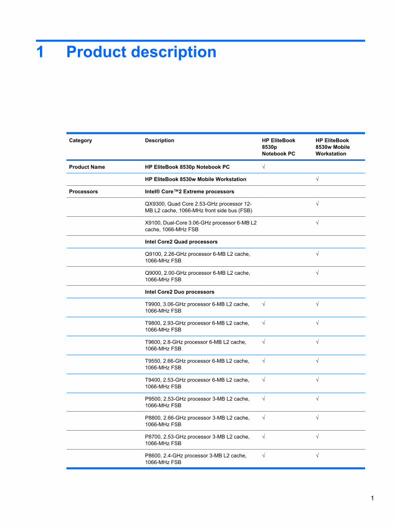
Category Description HP EliteBook8530pNotebook PC
HP EliteBook8530w MobileWorkstation
Product Name HP EliteBook 8530p Notebook PC √
HP EliteBook 8530w Mobile Workstation √
Processors Intel® Core™2 Extreme processors
QX9300, Quad Core 2.53-GHz processor 12-MB L2 cache, 1066-MHz front side bus (FSB)
√
X9100, Dual-Core 3.06-GHz processor 6-MB L2cache, 1066-MHz FSB
√
Intel Core2 Quad processors
Q9100, 2.26-GHz processor 6-MB L2 cache,1066-MHz FSB
√
Q9000, 2.00-GHz processor 6-MB L2 cache,1066-MHz FSB
√
Intel Core2 Duo processors
T9900, 3.06-GHz processor 6-MB L2 cache,1066-MHz FSB
√ √
T9800, 2.93-GHz processor 6-MB L2 cache,1066-MHz FSB
√ √
T9600, 2.8-GHz processor 6-MB L2 cache,1066-MHz FSB
√ √
T9550, 2.66-GHz processor 6-MB L2 cache,1066-MHz FSB
√ √
T9400, 2.53-GHz processor 6-MB L2 cache,1066-MHz FSB
√ √
P9500, 2.53-GHz processor 3-MB L2 cache,1066-MHz FSB
√ √
P8800, 2.66-GHz processor 3-MB L2 cache,1066-MHz FSB
√ √
P8700, 2.53-GHz processor 3-MB L2 cache,1066-MHz FSB
√ √
P8600, 2.4-GHz processor 3-MB L2 cache,1066-MHz FSB
√ √
1
Category Description HP EliteBook8530pNotebook PC
HP EliteBook8530w MobileWorkstation
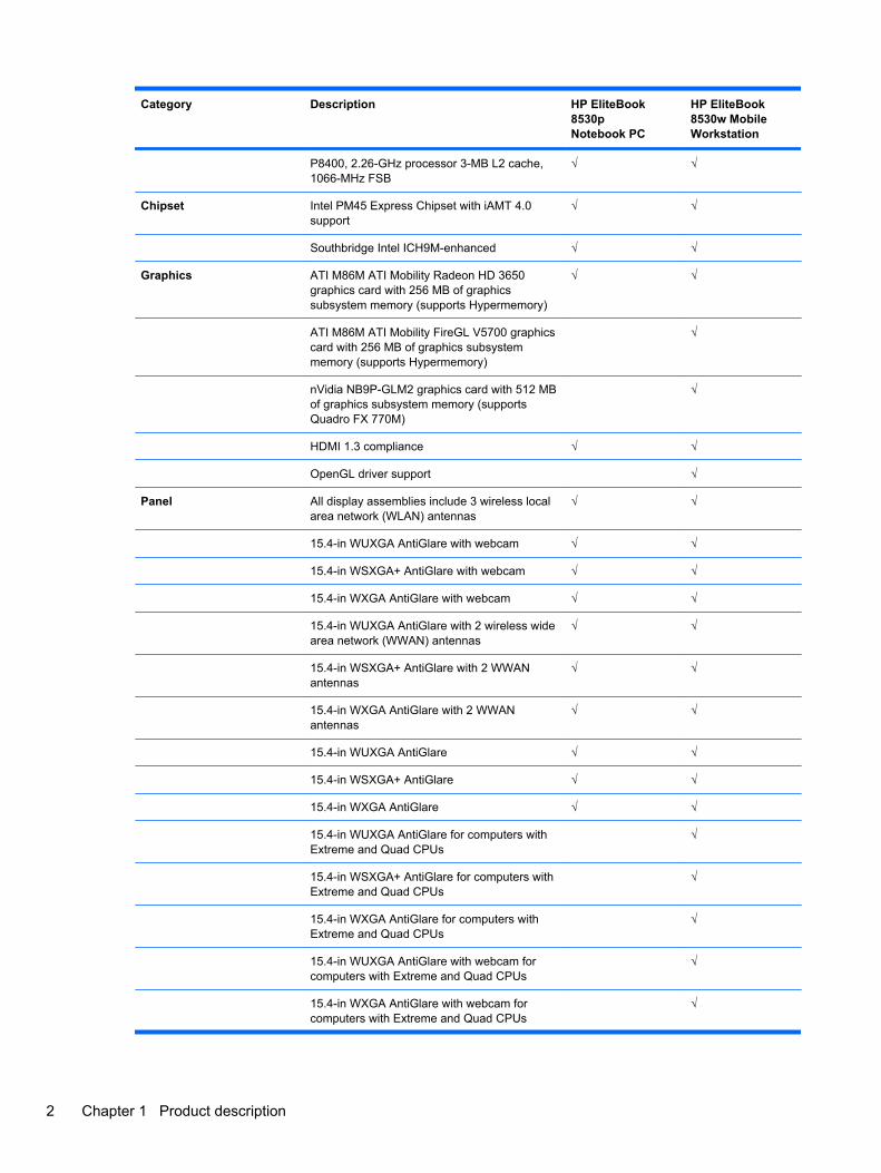
P8400, 2.26-GHz processor 3-MB L2 cache,1066-MHz FSB
√ √
Chipset Intel PM45 Express Chipset with iAMT 4.0support
√ √
Southbridge Intel ICH9M-enhanced √ √
Graphics ATI M86M ATI Mobility Radeon HD 3650graphics card with 256 MB of graphicssubsystem memory (supports Hypermemory)
√ √
ATI M86M ATI Mobility FireGL V5700 graphicscard with 256 MB of graphics subsystemmemory (supports Hypermemory)
√
nVidia NB9P-GLM2 graphics card with 512 MBof graphics subsystem memory (supportsQuadro FX 770M)
√
HDMI 1.3 compliance √ √
OpenGL driver support √
Panel All display assemblies include 3 wireless localarea network (WLAN) antennas
√ √
15.4-in WUXGA AntiGlare with webcam √ √
15.4-in WSXGA+ AntiGlare with webcam √ √
15.4-in WXGA AntiGlare with webcam √ √
15.4-in WUXGA AntiGlare with 2 wireless widearea network (WWAN) antennas
√ √
15.4-in WSXGA+ AntiGlare with 2 WWANantennas
√ √
15.4-in WXGA AntiGlare with 2 WWANantennas
√ √
15.4-in WUXGA AntiGlare √ √
15.4-in WSXGA+ AntiGlare √ √
15.4-in WXGA AntiGlare √ √
15.4-in WUXGA AntiGlare for computers withExtreme and Quad CPUs
√
15.4-in WSXGA+ AntiGlare for computers withExtreme and Quad CPUs
√
15.4-in WXGA AntiGlare for computers withExtreme and Quad CPUs
√
15.4-in WUXGA AntiGlare with webcam forcomputers with Extreme and Quad CPUs
√
15.4-in WXGA AntiGlare with webcam forcomputers with Extreme and Quad CPUs
√
2 Chapter 1 Product description
Category Description HP EliteBook8530pNotebook PC
HP EliteBook8530w MobileWorkstation
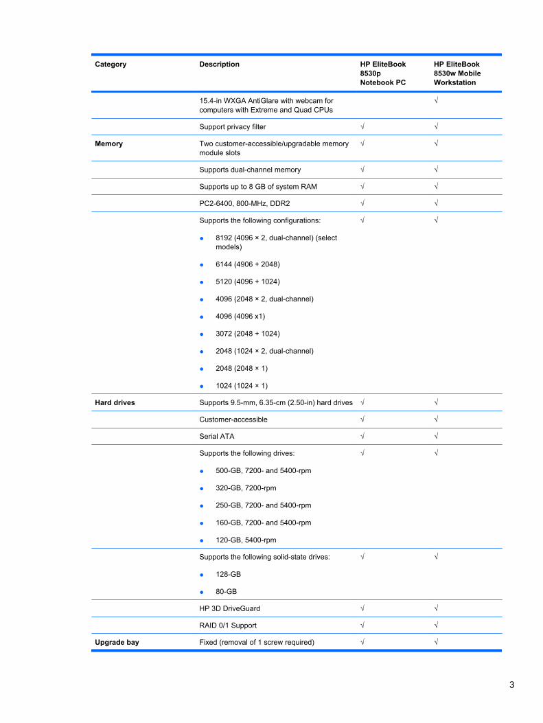
15.4-in WXGA AntiGlare with webcam forcomputers with Extreme and Quad CPUs
√
Support privacy filter √ √
Memory Two customer-accessible/upgradable memorymodule slots
√ √
Supports dual-channel memory √ √
Supports up to 8 GB of system RAM √ √
PC2-6400, 800-MHz, DDR2 √ √
Supports the following configurations:
● 8192 (4096 × 2, dual-channel) (selectmodels)
● 6144 (4906 + 2048)
● 5120 (4096 + 1024)
● 4096 (2048 × 2, dual-channel)
● 4096 (4096 x1)
● 3072 (2048 + 1024)
● 2048 (1024 × 2, dual-channel)
● 2048 (2048 × 1)
● 1024 (1024 × 1)
√ √
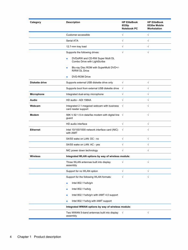
Hard drives Supports 9.5-mm, 6.35-cm (2.50-in) hard drives √ √
Customer-accessible √ √
Serial ATA √ √
Supports the following drives:
● 500-GB, 7200- and 5400-rpm
● 320-GB, 7200-rpm
● 250-GB, 7200- and 5400-rpm
● 160-GB, 7200- and 5400-rpm
● 120-GB, 5400-rpm
√ √
Supports the following solid-state drives:
● 128-GB
● 80-GB
√ √
HP 3D DriveGuard √ √
RAID 0/1 Support √ √
Upgrade bay Fixed (removal of 1 screw required) √ √
3
Category Description HP EliteBook8530pNotebook PC
HP EliteBook8530w MobileWorkstation
Customer-accessible √ √
Serial ATA √ √
12.7-mm tray load √ √
Supports the following drives:
● DVD±RW and CD-RW Super Multi DLCombo Drive with LightScribe
● Blu-ray Disc ROM with SuperMulti DVD+/-R/RW DL Drive
● DVD-ROM Drive
√ √
Diskette drive Supports external USB diskette drive only √ √
Supports boot from external USB diskette drive √ √
Microphone Integrated dual-array microphone √ √
Audio HD audio - ADI 1984A √ √
Webcam Integrated 2.1-megpixel webcam with businesscard reader support
√ √
Modem 56K V.92 1.5-in data/fax modem with digital lineguard
√ √
HD audio interface √ √
Ethernet Intel 10/100/1000 network interface card (NIC)with iAMT
√ √
S4/S5 wake on LAN: DC - no √ √
S4/S5 wake on LAN: AC - yes √ √
NIC power down technology √ √
Wireless Integrated WLAN options by way of wireless module:
Three WLAN antennas built into displayassembly
√ √
Support for no WLAN option √ √
Support for the following WLAN formats:
● Intel 802.11a/b/g/n
● Intel 802.11a/b/g
● Intel 802.11a/b/g/n with iAMT 4.0 support
● Intel 802.11a/b/g with iAMT support
√ √
Integrated WWAN options by way of wireless module:
Two WWAN 5-band antennas built into displayassembly
√ √
4 Chapter 1 Product description
Category Description HP EliteBook8530pNotebook PC
HP EliteBook8530w MobileWorkstation
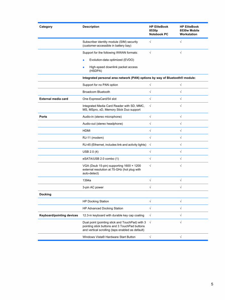
Subscriber identity module (SIM) security(customer-accessible in battery bay)
√ √
Support for the following WWAN formats:
● Evolution-data optimized (EVDO)
● High-speed downlink packet access(HSDPA)
√ √
Integrated personal area network (PAN) options by way of Bluetooth® module:
Support for no PAN option √ √
Broadcom Bluetooth √ √
External media card One ExpressCard/54 slot √ √
Integrated Media Card Reader with SD, MMC,MS, MSpro, xD, Memory Stick Duo support
√ √
Ports Audio-in (stereo microphone) √ √
Audio-out (stereo headphone) √ √
HDMI √ √
RJ-11 (modem) √ √
RJ-45 (Ethernet, includes link and activity lights) √ √
USB 2.0 (4) √ √
eSATA/USB 2.0 combo (1) √ √
VGA (Dsub 15-pin) supporting 1600 × 1200external resolution at 75-GHz (hot plug withauto-detect)
√ √
1394a √ √
3-pin AC power √ √
Docking
HP Docking Station √ √
HP Advanced Docking Station √ √
Keyboard/pointing devices 12.3-in keyboard with durable key cap coating √ √
Dual point (pointing stick and TouchPad) with 3pointing stick buttons and 3 TouchPad buttonsand vertical scrolling (taps enabled as default)
√ √
Windows Vista® Hardware Start Button √ √
5
Category Description HP EliteBook8530pNotebook PC
HP EliteBook8530w MobileWorkstation
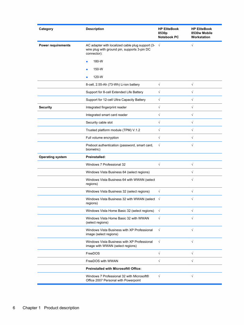
Power requirements AC adapter with localized cable plug support (3-wire plug with ground pin, supports 3-pin DCconnector):
● 180-W
● 150-W
● 120-W
√ √
8-cell, 2.55-Ah (73-Wh) Li-ion battery √ √
Support for 8-cell Extended Life Battery √ √
Support for 12-cell Ultra Capacity Battery √ √
Security Integrated fingerprint reader √ √
Integrated smart card reader √ √
Security cable slot √ √
Trusted platform module (TPM) V.1.2 √ √
Full volume encryption √ √
Preboot authentication (password, smart card,biometric)
√ √
Operating system Preinstalled:
Windows 7 Professional 32 √ √
Windows Vista Business 64 (select regions) √
Windows Vista Business 64 with WWAN (selectregions)
√
Windows Vista Business 32 (select regions) √ √
Windows Vista Business 32 with WWAN (selectregions)
√ √
Windows Vista Home Basic 32 (select regions) √ √
Windows Vista Home Basic 32 with WWAN(select regions)
√ √
Windows Vista Business with XP Professionalimage (select regions)
√ √
Windows Vista Business with XP Professionalimage with WWAN (select regions)
√ √
FreeDOS √ √
FreeDOS with WWAN √ √
Preinstalled with Microsoft® Office:
Windows 7 Professional 32 with Microsoft®Office 2007 Personal with Powerpoint
√ √
6 Chapter 1 Product description
Category Description HP EliteBook8530pNotebook PC
HP EliteBook8530w MobileWorkstation
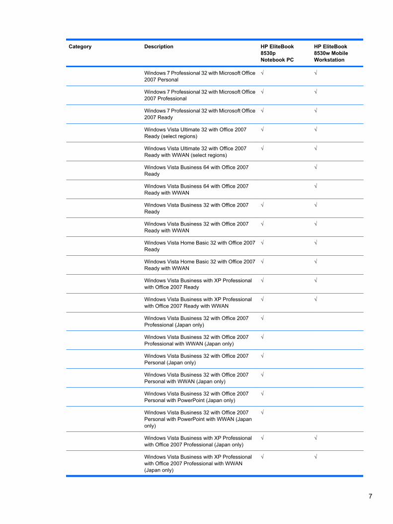
Windows 7 Professional 32 with Microsoft Office2007 Personal
√ √
Windows 7 Professional 32 with Microsoft Office2007 Professional
√ √
Windows 7 Professional 32 with Microsoft Office2007 Ready
√ √
Windows Vista Ultimate 32 with Office 2007Ready (select regions)
√ √
Windows Vista Ultimate 32 with Office 2007Ready with WWAN (select regions)
√ √
Windows Vista Business 64 with Office 2007Ready
√
Windows Vista Business 64 with Office 2007Ready with WWAN
√
Windows Vista Business 32 with Office 2007Ready
√ √
Windows Vista Business 32 with Office 2007Ready with WWAN
√ √
Windows Vista Home Basic 32 with Office 2007Ready
√ √
Windows Vista Home Basic 32 with Office 2007Ready with WWAN
√ √
Windows Vista Business with XP Professionalwith Office 2007 Ready
√ √
Windows Vista Business with XP Professionalwith Office 2007 Ready with WWAN
√ √
Windows Vista Business 32 with Office 2007Professional (Japan only)
√
Windows Vista Business 32 with Office 2007Professional with WWAN (Japan only)
√
Windows Vista Business 32 with Office 2007Personal (Japan only)
√
Windows Vista Business 32 with Office 2007Personal with WWAN (Japan only)
√
Windows Vista Business 32 with Office 2007Personal with PowerPoint (Japan only)
√
Windows Vista Business 32 with Office 2007Personal with PowerPoint with WWAN (Japanonly)
√
Windows Vista Business with XP Professionalwith Office 2007 Professional (Japan only)
√ √
Windows Vista Business with XP Professionalwith Office 2007 Professional with WWAN(Japan only)
√ √
7
Category Description HP EliteBook8530pNotebook PC
HP EliteBook8530w MobileWorkstation
Windows Vista Business with XP Professionalwith Office 2007 Personal (Japan only)
√ √
Windows Vista Business with XP Professionalwith Office 2007 Personal with WWAN (Japanonly)
√ √
Windows Vista Business with XP Professionalwith Office 2007 Personal with PowerPoint(Japan only)
√ √
Windows Vista Business with XP Professionalwith Office 2007 Personal with PowerPoint withWWAN (Japan only)
√ √
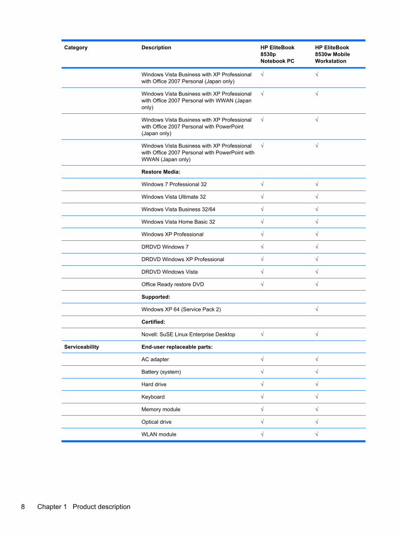
Restore Media:
Windows 7 Professional 32 √ √
Windows Vista Ultimate 32 √ √
Windows Vista Business 32/64 √ √
Windows Vista Home Basic 32 √ √
Windows XP Professional √ √
DRDVD Windows 7 √ √
DRDVD Windows XP Professional √ √
DRDVD Windows Vista √ √
Office Ready restore DVD √ √
Supported:
Windows XP 64 (Service Pack 2) √
Certified:
Novell: SuSE Linux Enterprise Desktop √ √
Serviceability End-user replaceable parts:
AC adapter √ √
Battery (system) √ √
Hard drive √ √
Keyboard √ √
Memory module √ √
Optical drive √ √
WLAN module √ √
8 Chapter 1 Product description
2 External component identification
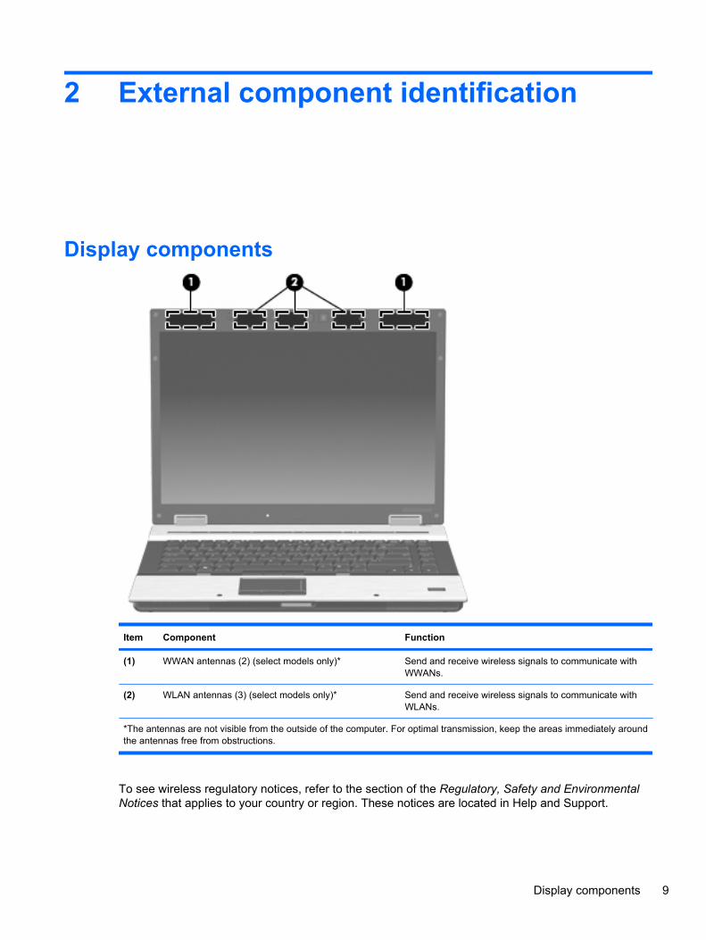
Display components
Item Component Function
(1) WWAN antennas (2) (select models only)* Send and receive wireless signals to communicate withWWANs.
(2) WLAN antennas (3) (select models only)* Send and receive wireless signals to communicate withWLANs.
*The antennas are not visible from the outside of the computer. For optimal transmission, keep the areas immediately aroundthe antennas free from obstructions.
To see wireless regulatory notices, refer to the section of the Regulatory, Safety and EnvironmentalNotices that applies to your country or region. These notices are located in Help and Support.
Display components 9
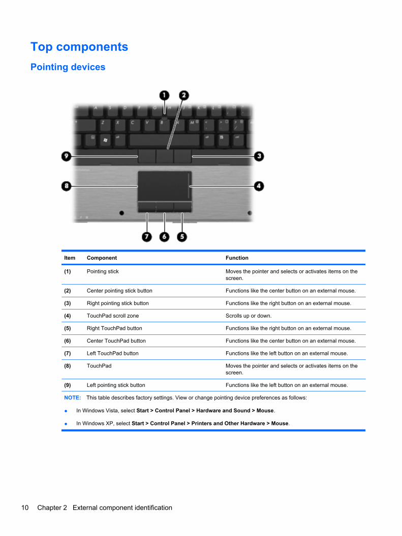
Top componentsPointing devices
Item Component Function
(1) Pointing stick Moves the pointer and selects or activates items on thescreen.
(2) Center pointing stick button Functions like the center button on an external mouse.
(3) Right pointing stick button Functions like the right button on an external mouse.
(4) TouchPad scroll zone Scrolls up or down.
(5) Right TouchPad button Functions like the right button on an external mouse.
(6) Center TouchPad button Functions like the center button on an external mouse.
(7) Left TouchPad button Functions like the left button on an external mouse.
(8) TouchPad Moves the pointer and selects or activates items on thescreen.
(9) Left pointing stick button Functions like the left button on an external mouse.
NOTE: This table describes factory settings. View or change pointing device preferences as follows:
● In Windows Vista, select Start > Control Panel > Hardware and Sound > Mouse.
● In Windows XP, select Start > Control Panel > Printers and Other Hardware > Mouse.
10 Chapter 2 External component identification

Buttons, switches, and fingerprint reader
Item Component Function
(1) Power button ● When the computer is off, press the button to turn onthe computer.
● When the computer is on, press the button to shutdown the computer.
● When the computer is in the Sleep state (WindowsVista) or in Standby (Windows XP), press the buttonbriefly to exit the Sleep state or Standby.
● When the computer is in Hibernation, press the buttonbriefly to exit Hibernation.
If the computer has stopped responding and Windows®shutdown procedures are ineffective, press and hold thepower button for at least 5 seconds to turn off the computer.
To learn more about power settings, follow these steps:
● In Windows Vista, select Start > Control Panel >System and Maintenance > Power Options.
● In Windows XP, select Start > Control Panel >System and Maintenance > Power Options.
(2) Info button Launches Info Center, which enables you to open varioussoftware solutions.
Top components 11
Item Component Function
(3) Wireless button Turns the wireless feature on or off, but does not establisha wireless connection.
NOTE: A wireless network must be set up in order toestablish a wireless connection.
(4) Internal display switch Turns off the display if the display is closed while the poweris on.
(5) Presentation button Starts the presentation feature.
(6) Volume mute button Mutes and restores speaker sound.
(7) Volume scroll zone Adjusts speaker volume. Slide your finger to the left todecrease volume and to the right to increase volume. Youcan also press the left side of the volume scroll zone todecrease volume, or press the right side of the volumescroll zone to increase volume.
(8) HP Fingerprint Sensor (finger print reader) Allows a fingerprint logon to Windows, instead of apassword logon.
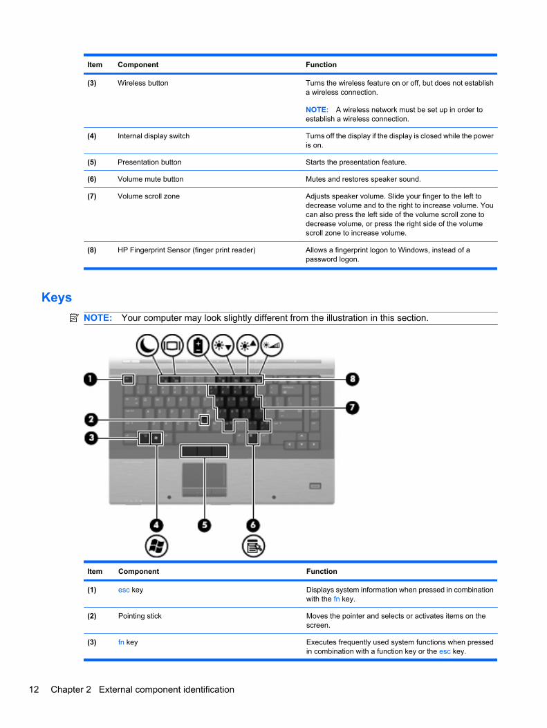
KeysNOTE: Your computer may look slightly different from the illustration in this section.
Item Component Function
(1) esc key Displays system information when pressed in combinationwith the fn key.
(2) Pointing stick Moves the pointer and selects or activates items on thescreen.
(3) fn key Executes frequently used system functions when pressedin combination with a function key or the esc key.
12 Chapter 2 External component identification
Item Component Function
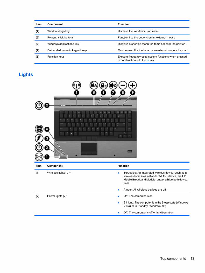
(4) Windows logo key Displays the Windows Start menu.
(5) Pointing stick buttons Function like the buttons on an external mouse
(6) Windows applications key Displays a shortcut menu for items beneath the pointer.
(7) Embedded numeric keypad keys Can be used like the keys on an external numeric keypad.
(8) Function keys Execute frequently used system functions when pressedin combination with the fn key.
Lights
Item Component Function
(1) Wireless lights (2)† ● Turquoise: An integrated wireless device, such as awireless local area network (WLAN) device, the HPMobile Broadband Module, and/or a Bluetooth device,is on.
● Amber: All wireless devices are off.
(2) Power lights (2)* ● On: The computer is on.
● Blinking: The computer is in the Sleep state (WindowsVista) or in Standby (Windows XP).
● Off: The computer is off or in Hibernation.
Top components 13
Item Component Function
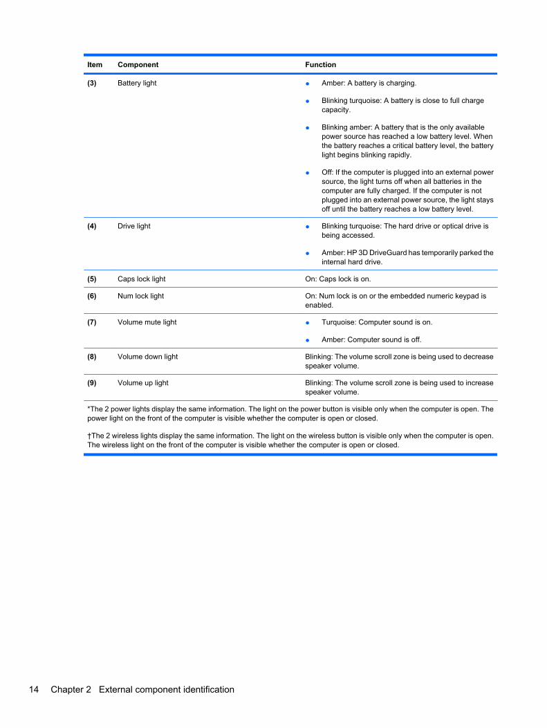
(3) Battery light ● Amber: A battery is charging.
● Blinking turquoise: A battery is close to full chargecapacity.
● Blinking amber: A battery that is the only availablepower source has reached a low battery level. Whenthe battery reaches a critical battery level, the batterylight begins blinking rapidly.
● Off: If the computer is plugged into an external powersource, the light turns off when all batteries in thecomputer are fully charged. If the computer is notplugged into an external power source, the light staysoff until the battery reaches a low battery level.
(4) Drive light ● Blinking turquoise: The hard drive or optical drive isbeing accessed.
● Amber: HP 3D DriveGuard has temporarily parked theinternal hard drive.
(5) Caps lock light On: Caps lock is on.
(6) Num lock light On: Num lock is on or the embedded numeric keypad isenabled.
(7) Volume mute light ● Turquoise: Computer sound is on.
● Amber: Computer sound is off.
(8) Volume down light Blinking: The volume scroll zone is being used to decreasespeaker volume.
(9) Volume up light Blinking: The volume scroll zone is being used to increasespeaker volume.
*The 2 power lights display the same information. The light on the power button is visible only when the computer is open. Thepower light on the front of the computer is visible whether the computer is open or closed.
†The 2 wireless lights display the same information. The light on the wireless button is visible only when the computer is open.The wireless light on the front of the computer is visible whether the computer is open or closed.
14 Chapter 2 External component identification
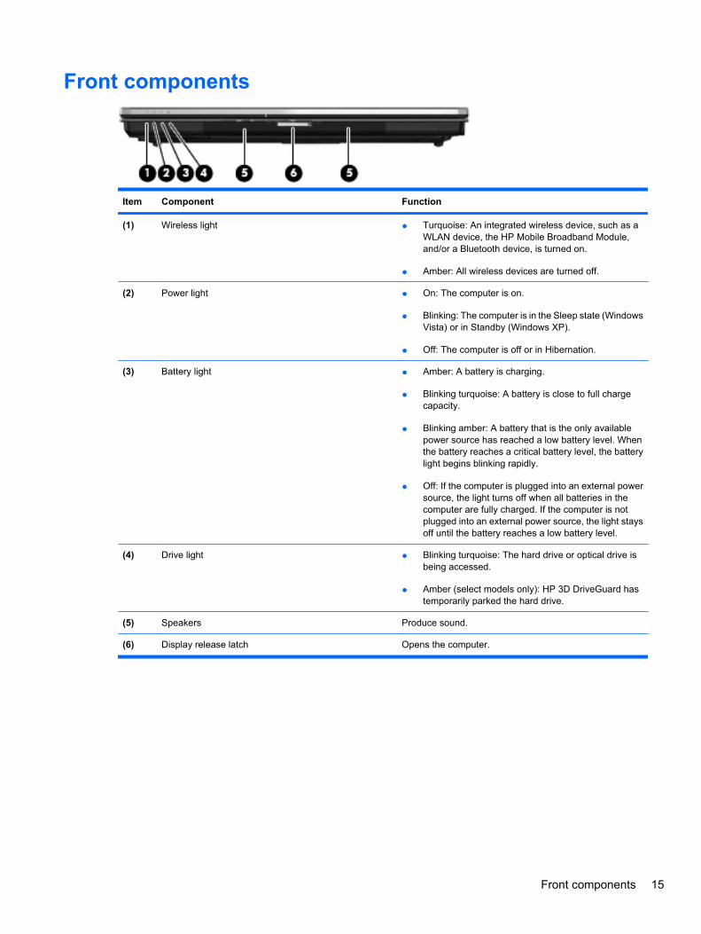
Front components
Item Component Function
(1) Wireless light ● Turquoise: An integrated wireless device, such as aWLAN device, the HP Mobile Broadband Module,and/or a Bluetooth device, is turned on.
● Amber: All wireless devices are turned off.
(2) Power light ● On: The computer is on.
● Blinking: The computer is in the Sleep state (WindowsVista) or in Standby (Windows XP).
● Off: The computer is off or in Hibernation.
(3) Battery light ● Amber: A battery is charging.
● Blinking turquoise: A battery is close to full chargecapacity.
● Blinking amber: A battery that is the only availablepower source has reached a low battery level. Whenthe battery reaches a critical battery level, the batterylight begins blinking rapidly.
● Off: If the computer is plugged into an external powersource, the light turns off when all batteries in thecomputer are fully charged. If the computer is notplugged into an external power source, the light staysoff until the battery reaches a low battery level.
(4) Drive light ● Blinking turquoise: The hard drive or optical drive isbeing accessed.
● Amber (select models only): HP 3D DriveGuard hastemporarily parked the hard drive.
(5) Speakers Produce sound.
(6) Display release latch Opens the computer.
Front components 15
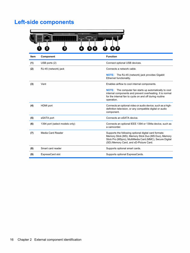
Left-side components
Item Component Function
(1) USB ports (2) Connect optional USB devices.
(2) RJ-45 (network) jack Connects a network cable.
NOTE: The RJ-45 (network) jack provides GigabitEthernet functionality.
(3) Vent Enables airflow to cool internal components.
NOTE: The computer fan starts up automatically to coolinternal components and prevent overheating. It is normalfor the internal fan to cycle on and off during routineoperation.
(4) HDMI port Connects an optional video or audio device, such as a high-definition television, or any compatible digital or audiocomponent.
(5) eSATA port Connects an eSATA device.
(6) 1394 port (select models only) Connects an optional IEEE 1394 or 1394a device, such asa camcorder.
(7) Media Card Reader Supports the following optional digital card formats:Memory Stick (MS), Memory Stick Duo (MS Duo), MemoryStick Pro (MSpro), MultiMedia Card (MMC), Secure Digital(SD) Memory Card, and xD-Picture Card.
(8) Smart card reader Supports optional smart cards.
(9) ExpressCard slot Supports optional ExpressCards.
16 Chapter 2 External component identification
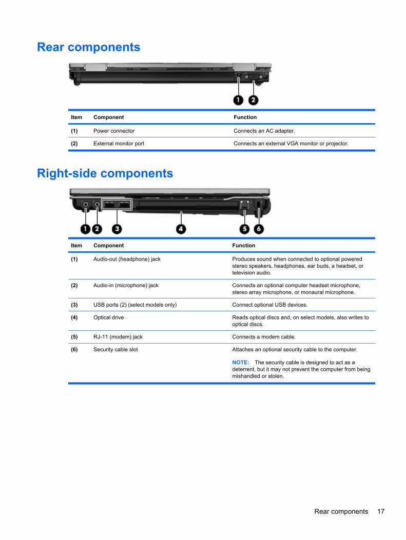
Rear components
Item Component Function
(1) Power connector Connects an AC adapter.
(2) External monitor port Connects an external VGA monitor or projector.
Right-side components
Item Component Function
(1) Audio-out (headphone) jack Produces sound when connected to optional poweredstereo speakers, headphones, ear buds, a headset, ortelevision audio.
(2) Audio-in (microphone) jack Connects an optional computer headset microphone,stereo array microphone, or monaural microphone.
(3) USB ports (2) (select models only) Connect optional USB devices.
(4) Optical drive Reads optical discs and, on select models, also writes tooptical discs.
(5) RJ-11 (modem) jack Connects a modem cable.
(6) Security cable slot Attaches an optional security cable to the computer.
NOTE: The security cable is designed to act as adeterrent, but it may not prevent the computer from beingmishandled or stolen.
Rear components 17
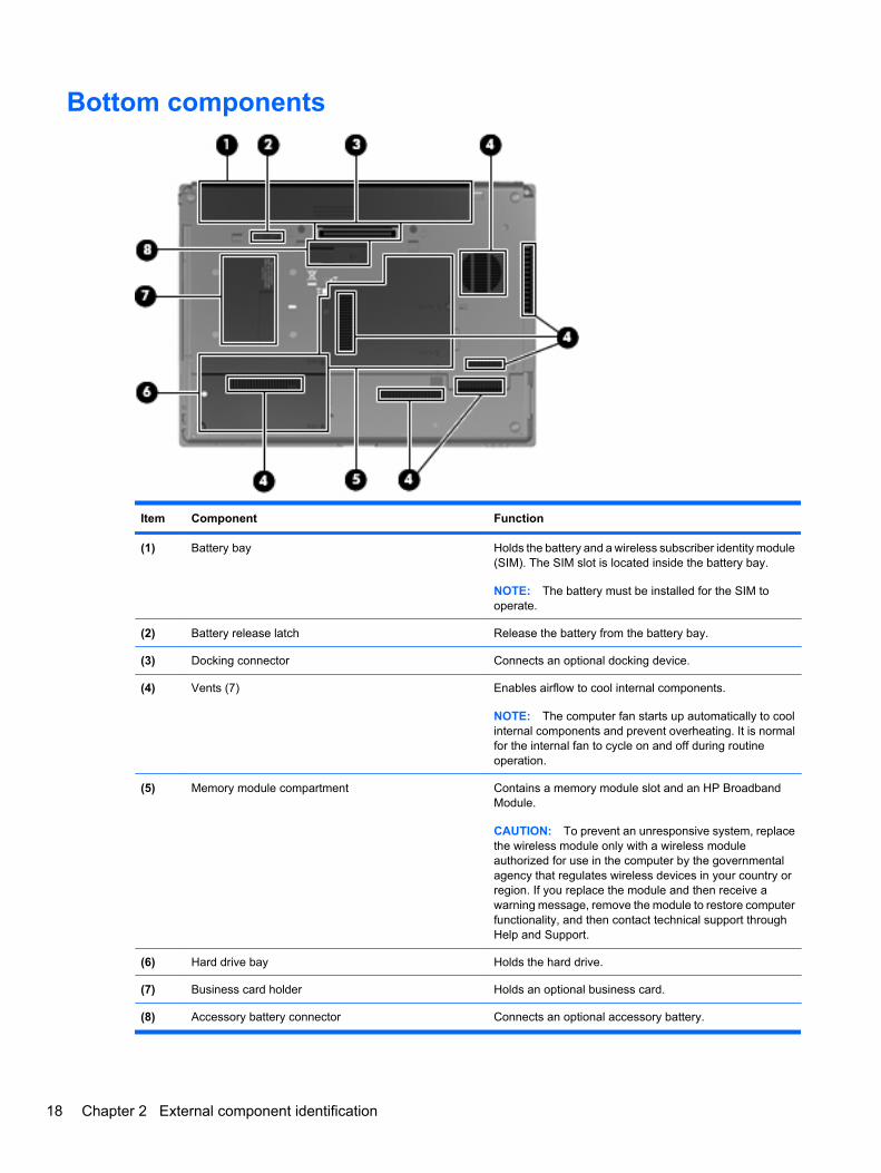
Bottom components
Item Component Function
(1) Battery bay Holds the battery and a wireless subscriber identity module(SIM). The SIM slot is located inside the battery bay.
NOTE: The battery must be installed for the SIM tooperate.
(2) Battery release latch Release the battery from the battery bay.
(3) Docking connector Connects an optional docking device.
(4) Vents (7) Enables airflow to cool internal components.
NOTE: The computer fan starts up automatically to coolinternal components and prevent overheating. It is normalfor the internal fan to cycle on and off during routineoperation.
(5) Memory module compartment Contains a memory module slot and an HP BroadbandModule.
CAUTION: To prevent an unresponsive system, replacethe wireless module only with a wireless moduleauthorized for use in the computer by the governmentalagency that regulates wireless devices in your country orregion. If you replace the module and then receive awarning message, remove the module to restore computerfunctionality, and then contact technical support throughHelp and Support.
(6) Hard drive bay Holds the hard drive.
(7) Business card holder Holds an optional business card.
(8) Accessory battery connector Connects an optional accessory battery.
18 Chapter 2 External component identification
3 Illustrated parts catalog
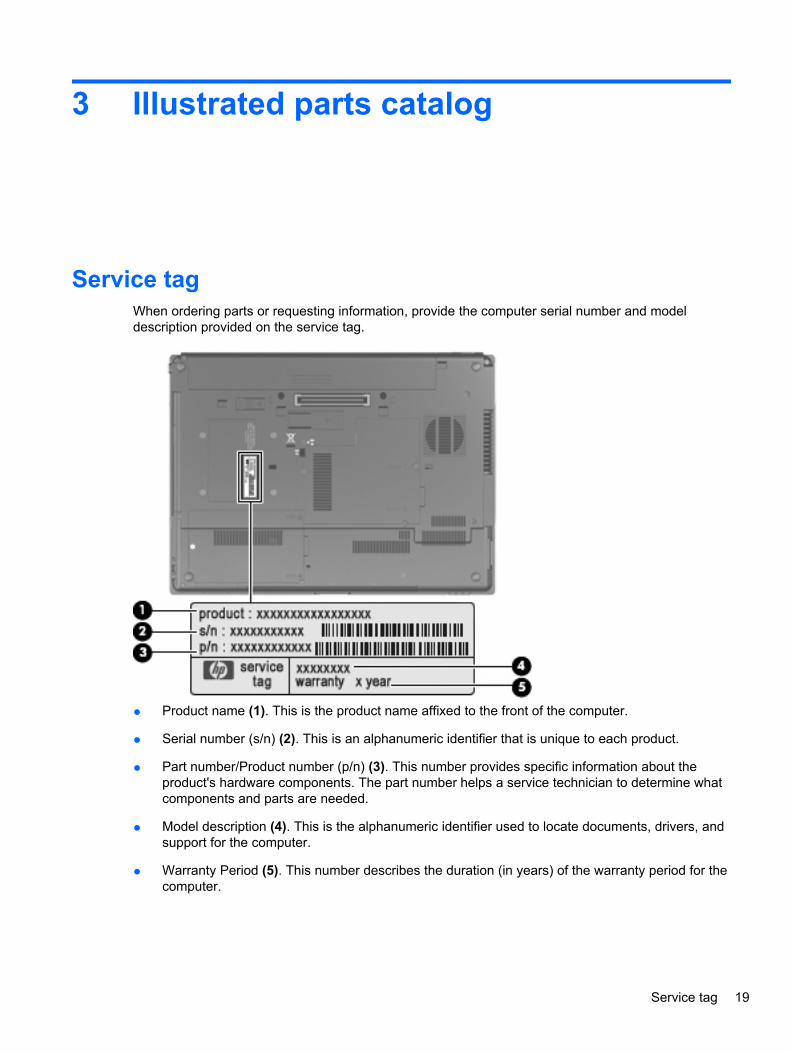
Service tagWhen ordering parts or requesting information, provide the computer serial number and modeldescription provided on the service tag.
● Product name (1). This is the product name affixed to the front of the computer.
● Serial number (s/n) (2). This is an alphanumeric identifier that is unique to each product.
● Part number/Product number (p/n) (3). This number provides specific information about theproduct's hardware components. The part number helps a service technician to determine whatcomponents and parts are needed.
● Model description (4). This is the alphanumeric identifier used to locate documents, drivers, andsupport for the computer.
● Warranty Period (5). This number describes the duration (in years) of the warranty period for thecomputer.
Service tag 19
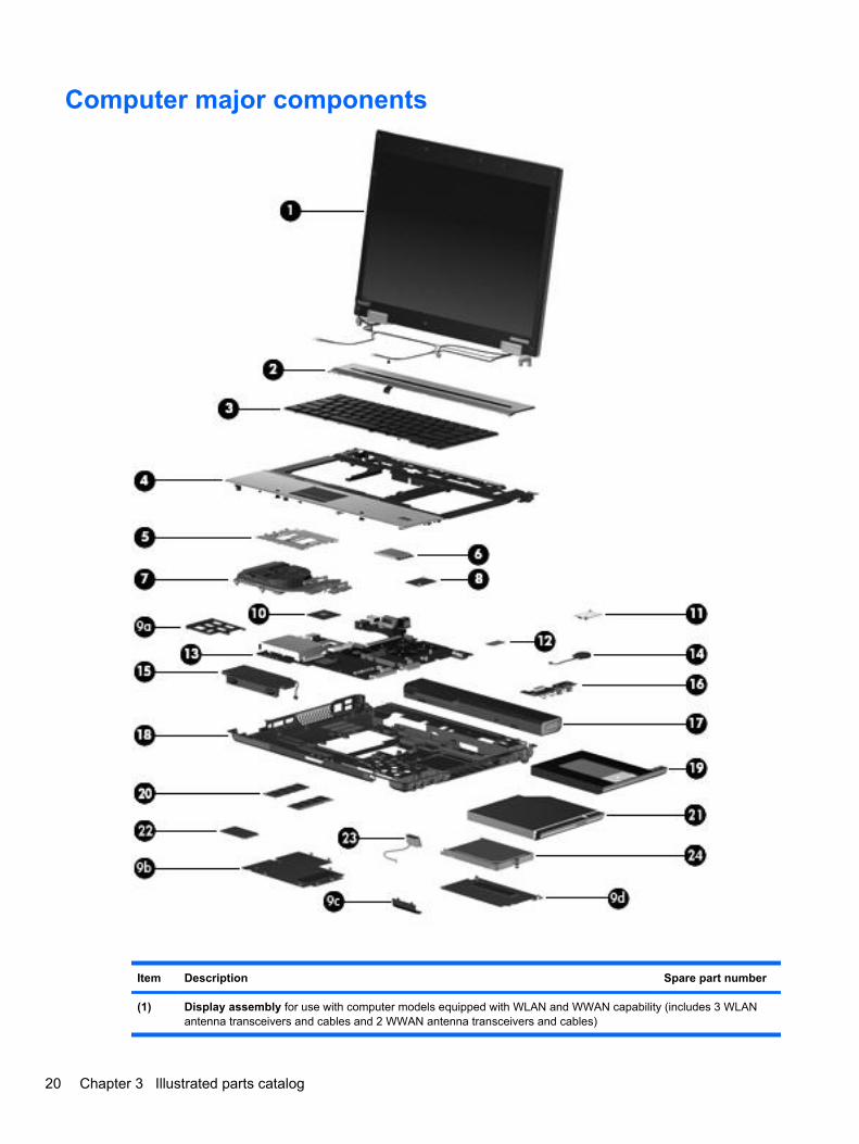
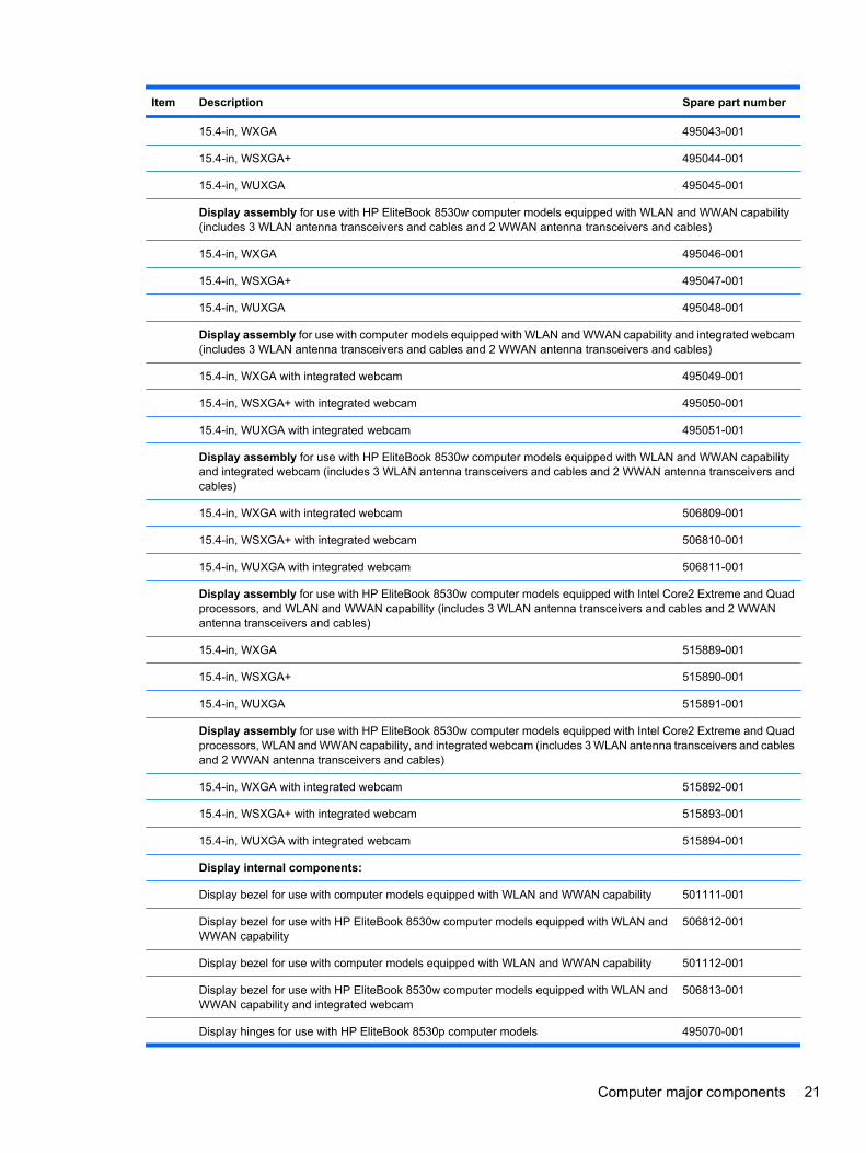
Computer major components
Item Description Spare part number
(1) Display assembly for use with computer models equipped with WLAN and WWAN capability (includes 3 WLANantenna transceivers and cables and 2 WWAN antenna transceivers and cables)
20 Chapter 3 Illustrated parts catalog
Item Description Spare part number
15.4-in, WXGA 495043-001
15.4-in, WSXGA+ 495044-001
15.4-in, WUXGA 495045-001
Display assembly for use with HP EliteBook 8530w computer models equipped with WLAN and WWAN capability(includes 3 WLAN antenna transceivers and cables and 2 WWAN antenna transceivers and cables)
15.4-in, WXGA 495046-001
15.4-in, WSXGA+ 495047-001
15.4-in, WUXGA 495048-001
Display assembly for use with computer models equipped with WLAN and WWAN capability and integrated webcam(includes 3 WLAN antenna transceivers and cables and 2 WWAN antenna transceivers and cables)
15.4-in, WXGA with integrated webcam 495049-001
15.4-in, WSXGA+ with integrated webcam 495050-001
15.4-in, WUXGA with integrated webcam 495051-001
Display assembly for use with HP EliteBook 8530w computer models equipped with WLAN and WWAN capabilityand integrated webcam (includes 3 WLAN antenna transceivers and cables and 2 WWAN antenna transceivers andcables)
15.4-in, WXGA with integrated webcam 506809-001
15.4-in, WSXGA+ with integrated webcam 506810-001
15.4-in, WUXGA with integrated webcam 506811-001
Display assembly for use with HP EliteBook 8530w computer models equipped with Intel Core2 Extreme and Quadprocessors, and WLAN and WWAN capability (includes 3 WLAN antenna transceivers and cables and 2 WWANantenna transceivers and cables)
15.4-in, WXGA 515889-001
15.4-in, WSXGA+ 515890-001
15.4-in, WUXGA 515891-001
Display assembly for use with HP EliteBook 8530w computer models equipped with Intel Core2 Extreme and Quadprocessors, WLAN and WWAN capability, and integrated webcam (includes 3 WLAN antenna transceivers and cablesand 2 WWAN antenna transceivers and cables)
15.4-in, WXGA with integrated webcam 515892-001
15.4-in, WSXGA+ with integrated webcam 515893-001
15.4-in, WUXGA with integrated webcam 515894-001
Display internal components:
Display bezel for use with computer models equipped with WLAN and WWAN capability 501111-001
Display bezel for use with HP EliteBook 8530w computer models equipped with WLAN andWWAN capability
506812-001
Display bezel for use with computer models equipped with WLAN and WWAN capability 501112-001
Display bezel for use with HP EliteBook 8530w computer models equipped with WLAN andWWAN capability and integrated webcam
506813-001
Display hinges for use with HP EliteBook 8530p computer models 495070-001
Computer major components 21
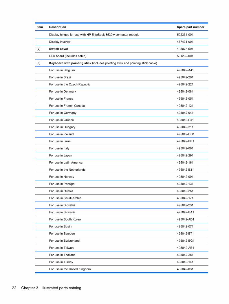
Item Description Spare part number
Display hinges for use with HP EliteBook 8530w computer models 502334-001
Display inverter 487431-001
(2) Switch cover 495073-001
LED board (includes cable) 501232-001
(3) Keyboard with pointing stick (includes pointing stick and pointing stick cable)
For use in Belgium 495042-A41
For use in Brazil 495042-201
For use in the Czech Republic 495042-221
For use in Denmark 495042-081
For use in France 495042-051
For use in French Canada 495042-121
For use in Germany 495042-041
For use in Greece 495042-DJ1
For use in Hungary 495042-211
For use in Iceland 495042-DD1
For use in Israel 495042-BB1
For use in Italy 495042-061
For use in Japan 495042-291
For use in Latin America 495042-161
For use in the Netherlands 495042-B31
For use in Norway 495042-091
For use in Portugal 495042-131
For use in Russia 495042-251
For use in Saudi Arabia 495042-171
For use in Slovakia 495042-231
For use in Slovenia 495042-BA1
For use in South Korea 495042-AD1
For use in Spain 495042-071
For use in Sweden 495042-B71
For use in Switzerland 495042-BG1
For use in Taiwan 495042-AB1
For use in Thailand 495042-281
For use in Turkey 495042-141
For use in the United Kingdom 495042-031
22 Chapter 3 Illustrated parts catalog
Item Description Spare part number
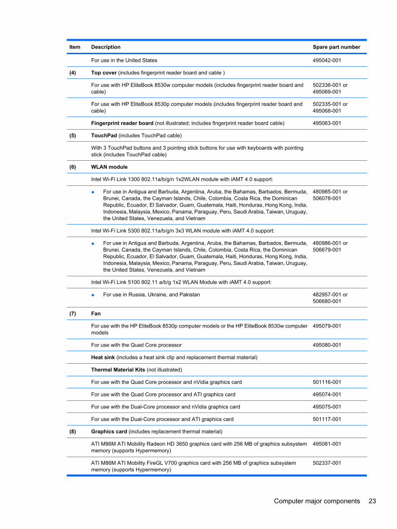
For use in the United States 495042-001
(4) Top cover (includes fingerprint reader board and cable )
For use with HP EliteBook 8530w computer models (includes fingerprint reader board andcable)
502336-001 or495069-001
For use with HP EliteBook 8530p computer models (includes fingerprint reader board andcable)
502335-001 or495068-001
Fingerprint reader board (not illustrated; includes fingerprint reader board cable) 495063-001
(5) TouchPad (includes TouchPad cable)
With 3 TouchPad buttons and 3 pointing stick buttons for use with keyboards with pointingstick (includes TouchPad cable)
(6) WLAN module
Intel Wi-Fi Link 1300 802.11a/b/g/n 1x2WLAN module with iAMT 4.0 support:
● For use in Antigua and Barbuda, Argentina, Aruba, the Bahamas, Barbados, Bermuda,Brunei, Canada, the Cayman Islands, Chile, Colombia, Costa Rica, the DominicanRepublic, Ecuador, El Salvador, Guam, Guatemala, Haiti, Honduras, Hong Kong, India,Indonesia, Malaysia, Mexico, Panama, Paraguay, Peru, Saudi Arabia, Taiwan, Uruguay,the United States, Venezuela, and Vietnam
480985-001 or506078-001
Intel Wi-Fi Link 5300 802.11a/b/g/n 3x3 WLAN module with iAMT 4.0 support:
● For use in Antigua and Barbuda, Argentina, Aruba, the Bahamas, Barbados, Bermuda,Brunei, Canada, the Cayman Islands, Chile, Colombia, Costa Rica, the DominicanRepublic, Ecuador, El Salvador, Guam, Guatemala, Haiti, Honduras, Hong Kong, India,Indonesia, Malaysia, Mexico, Panama, Paraguay, Peru, Saudi Arabia, Taiwan, Uruguay,the United States, Venezuela, and Vietnam
480986-001 or506679-001
Intel Wi-Fi Link 5100 802.11 a/b/g 1x2 WLAN Module with iAMT 4.0 support:
● For use in Russia, Ukraine, and Pakistan 482957-001 or506680-001
(7) Fan
For use with the HP EliteBook 8530p computer models or the HP EliteBook 8530w computermodels
495079-001
For use with the Quad Core processor 495080-001
Heat sink (includes a heat sink clip and replacement thermal material)
Thermal Material Kits (not illustrated)
For use with the Quad Core processor and nVidia graphics card 501116-001
For use with the Quad Core processor and ATI graphics card 495074-001
For use with the Dual-Core processor and nVidia graphics card 495075-001
For use with the Dual-Core processor and ATI graphics card 501117-001
(8) Graphics card (includes replacement thermal material)
ATI M86M ATI Mobility Radeon HD 3650 graphics card with 256 MB of graphics subsystemmemory (supports Hypermemory)
495081-001
ATI M86M ATI Mobility FireGL V700 graphics card with 256 MB of graphics subsystemmemory (supports Hypermemory)
502337-001
Computer major components 23
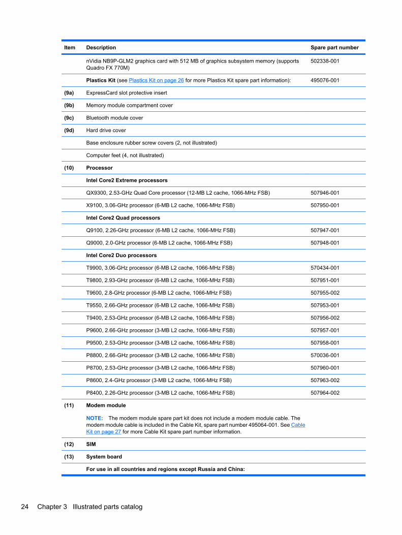
Item Description Spare part number
nVidia NB9P-GLM2 graphics card with 512 MB of graphics subsystem memory (supportsQuadro FX 770M)
502338-001
Plastics Kit (see Plastics Kit on page 26 for more Plastics Kit spare part information): 495076-001
(9a) ExpressCard slot protective insert
(9b) Memory module compartment cover
(9c) Bluetooth module cover
(9d) Hard drive cover
Base enclosure rubber screw covers (2, not illustrated)
Computer feet (4, not illustrated)
(10) Processor
Intel Core2 Extreme processors
QX9300, 2.53-GHz Quad Core processor (12-MB L2 cache, 1066-MHz FSB) 507946-001
X9100, 3.06-GHz processor (6-MB L2 cache, 1066-MHz FSB) 507950-001
Intel Core2 Quad processors
Q9100, 2.26-GHz processor (6-MB L2 cache, 1066-MHz FSB) 507947-001
Q9000, 2.0-GHz processor (6-MB L2 cache, 1066-MHz FSB) 507948-001
Intel Core2 Duo processors
T9900, 3.06-GHz processor (6-MB L2 cache, 1066-MHz FSB) 570434-001
T9800, 2.93-GHz processor (6-MB L2 cache, 1066-MHz FSB) 507951-001
T9600, 2.8-GHz processor (6-MB L2 cache, 1066-MHz FSB) 507955-002
T9550, 2.66-GHz processor (6-MB L2 cache, 1066-MHz FSB) 507953-001
T9400, 2.53-GHz processor (6-MB L2 cache, 1066-MHz FSB) 507956-002
P9600, 2.66-GHz processor (3-MB L2 cache, 1066-MHz FSB) 507957-001
P9500, 2.53-GHz processor (3-MB L2 cache, 1066-MHz FSB) 507958-001
P8800, 2.66-GHz processor (3-MB L2 cache, 1066-MHz FSB) 570036-001
P8700, 2.53-GHz processor (3-MB L2 cache, 1066-MHz FSB) 507960-001
P8600, 2.4-GHz processor (3-MB L2 cache, 1066-MHz FSB) 507963-002
P8400, 2.26-GHz processor (3-MB L2 cache, 1066-MHz FSB) 507964-002
(11) Modem module
NOTE: The modem module spare part kit does not include a modem module cable. Themodem module cable is included in the Cable Kit, spare part number 495064-001. See CableKit on page 27 for more Cable Kit spare part number information.
(12) SIM
(13) System board
For use in all countries and regions except Russia and China:
24 Chapter 3 Illustrated parts catalog
Item Description Spare part number
● For use in HP EliteBook 8530w models with Intel Core2 Extreme Quad-Core processors 500906-001
● For use in HP EliteBook 8530w models with Intel Core2 Extreme Dual-Core processors 500905-001
● For use in HP EliteBook 8530p and 8530w models with Intel Core2 Duo processors 500907-001
For use only in Russia and China:
● For use in HP EliteBook 8530w models with Intel Core2 Extreme Dual-Core processorsonly in Russia and China
510349-001
● For use in HP EliteBook 8530w models with Intel Core2 Extreme Quad-Core processorsonly in Russia and China
510350-001
● For use in HP EliteBook 8530p and 8530w models with Intel Core2 Duo processors onlyin Russia and China
510348-001
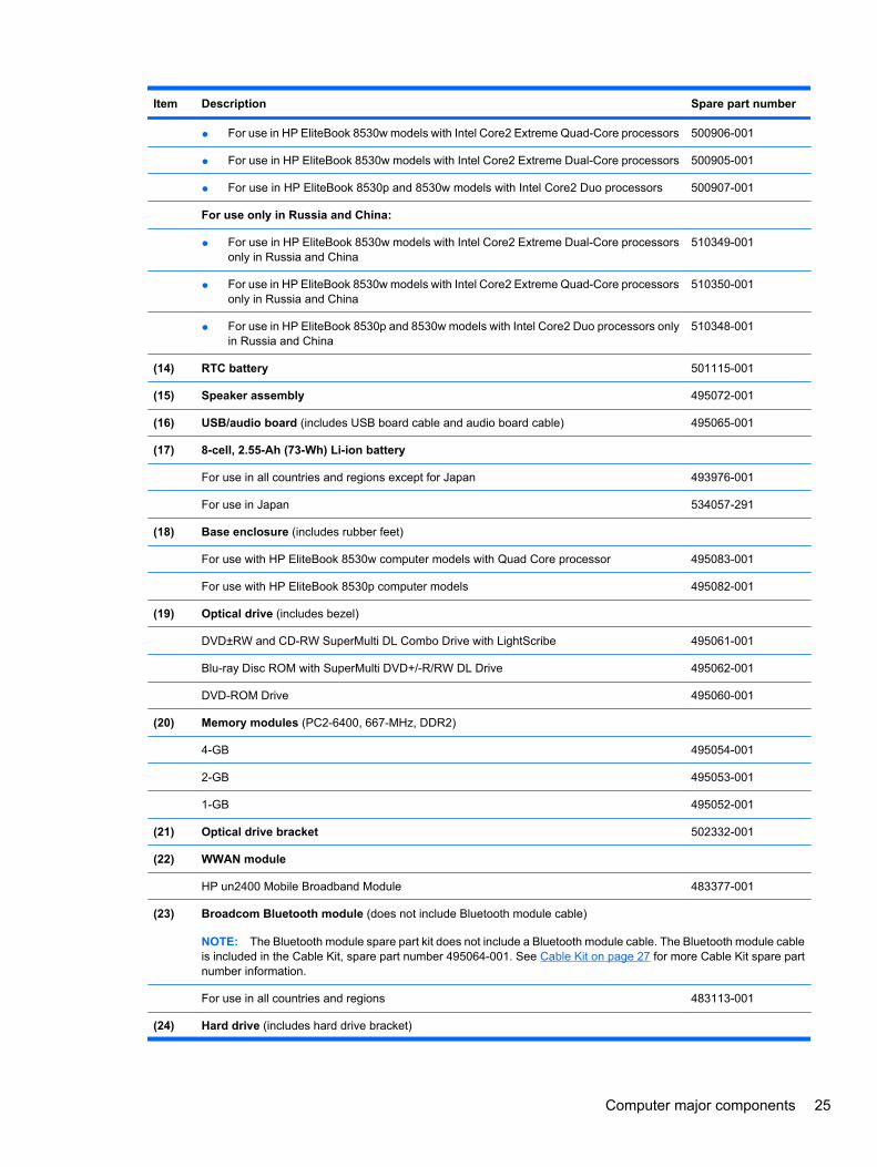
(14) RTC battery 501115-001
(15) Speaker assembly 495072-001
(16) USB/audio board (includes USB board cable and audio board cable) 495065-001
(17) 8-cell, 2.55-Ah (73-Wh) Li-ion battery
For use in all countries and regions except for Japan 493976-001
For use in Japan 534057-291
(18) Base enclosure (includes rubber feet)
For use with HP EliteBook 8530w computer models with Quad Core processor 495083-001
For use with HP EliteBook 8530p computer models 495082-001
(19) Optical drive (includes bezel)
DVD±RW and CD-RW SuperMulti DL Combo Drive with LightScribe 495061-001
Blu-ray Disc ROM with SuperMulti DVD+/-R/RW DL Drive 495062-001
DVD-ROM Drive 495060-001
(20) Memory modules (PC2-6400, 667-MHz, DDR2)
4-GB 495054-001
2-GB 495053-001
1-GB 495052-001
(21) Optical drive bracket 502332-001
(22) WWAN module
HP un2400 Mobile Broadband Module 483377-001
(23) Broadcom Bluetooth module (does not include Bluetooth module cable)
NOTE: The Bluetooth module spare part kit does not include a Bluetooth module cable. The Bluetooth module cableis included in the Cable Kit, spare part number 495064-001. See Cable Kit on page 27 for more Cable Kit spare partnumber information.
For use in all countries and regions 483113-001
(24) Hard drive (includes hard drive bracket)
Computer major components 25
Item Description Spare part number
500-GB, 7200-rpm hard drive 532108-001
500-GB, 5400-rpm hard drive 519893-001
320-GB, 7200-rpm 501118-001
250-GB, 7200-rpm 495059-001
250-GB, 5400-rpm 495058-001
160-GB, 7200-rpm 483186-001
160-GB, 7200-rpm hard drive (Seagate only) 580297-001
160-GB, 5400-rpm 514071-001
128-GB solid-state drive 574721-001
80-GB solid-state drive 501113-001
Cable Kit (not illustrated; see Cable Kit on page 27 for more Cable Kit spare part numberinformation)
495064-001
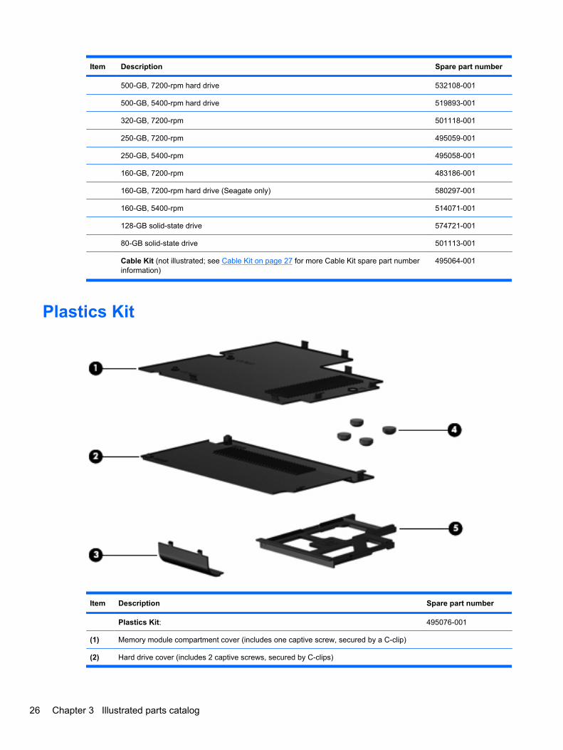
Plastics Kit
Item Description Spare part number
Plastics Kit: 495076-001
(1) Memory module compartment cover (includes one captive screw, secured by a C-clip)
(2) Hard drive cover (includes 2 captive screws, secured by C-clips)
26 Chapter 3 Illustrated parts catalog
Item Description Spare part number
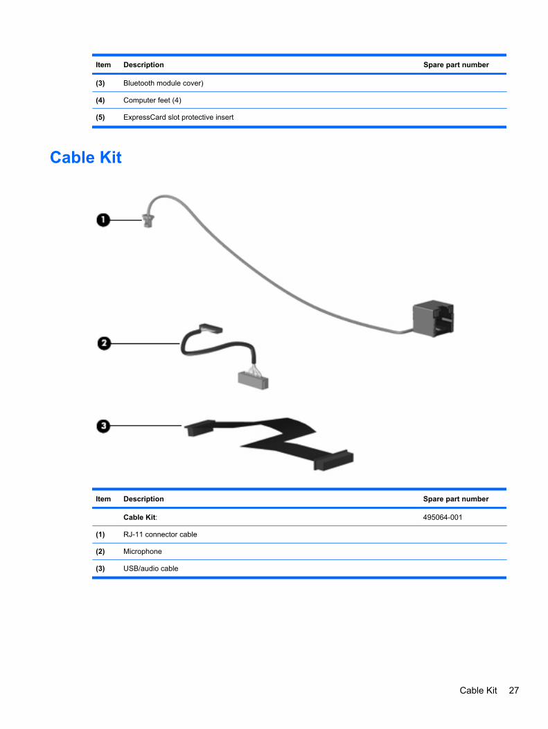
(3) Bluetooth module cover)
(4) Computer feet (4)
(5) ExpressCard slot protective insert
Cable Kit
Item Description Spare part number
Cable Kit: 495064-001
(1) RJ-11 connector cable
(2) Microphone
(3) USB/audio cable
Cable Kit 27
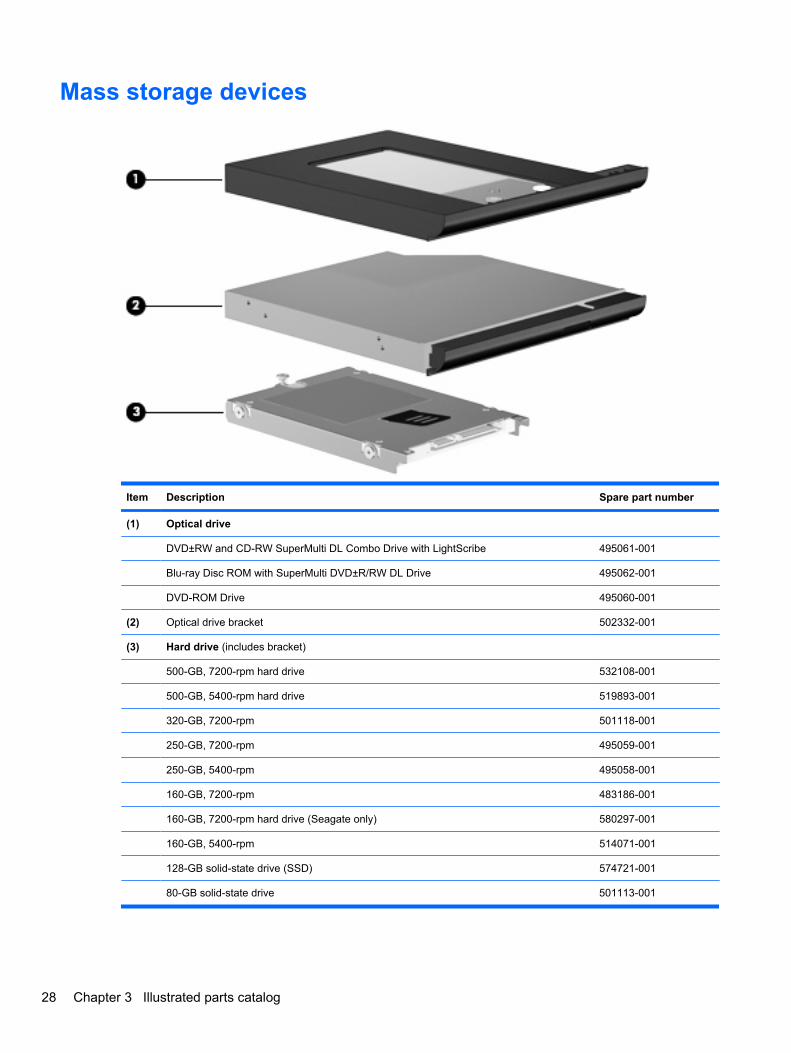
Mass storage devices
Item Description Spare part number
(1) Optical drive
DVD±RW and CD-RW SuperMulti DL Combo Drive with LightScribe 495061-001
Blu-ray Disc ROM with SuperMulti DVD±R/RW DL Drive 495062-001
DVD-ROM Drive 495060-001
(2) Optical drive bracket 502332-001
(3) Hard drive (includes bracket)
500-GB, 7200-rpm hard drive 532108-001
500-GB, 5400-rpm hard drive 519893-001
320-GB, 7200-rpm 501118-001
250-GB, 7200-rpm 495059-001
250-GB, 5400-rpm 495058-001
160-GB, 7200-rpm 483186-001
160-GB, 7200-rpm hard drive (Seagate only) 580297-001
160-GB, 5400-rpm 514071-001
128-GB solid-state drive (SSD) 574721-001
80-GB solid-state drive 501113-001
28 Chapter 3 Illustrated parts catalog
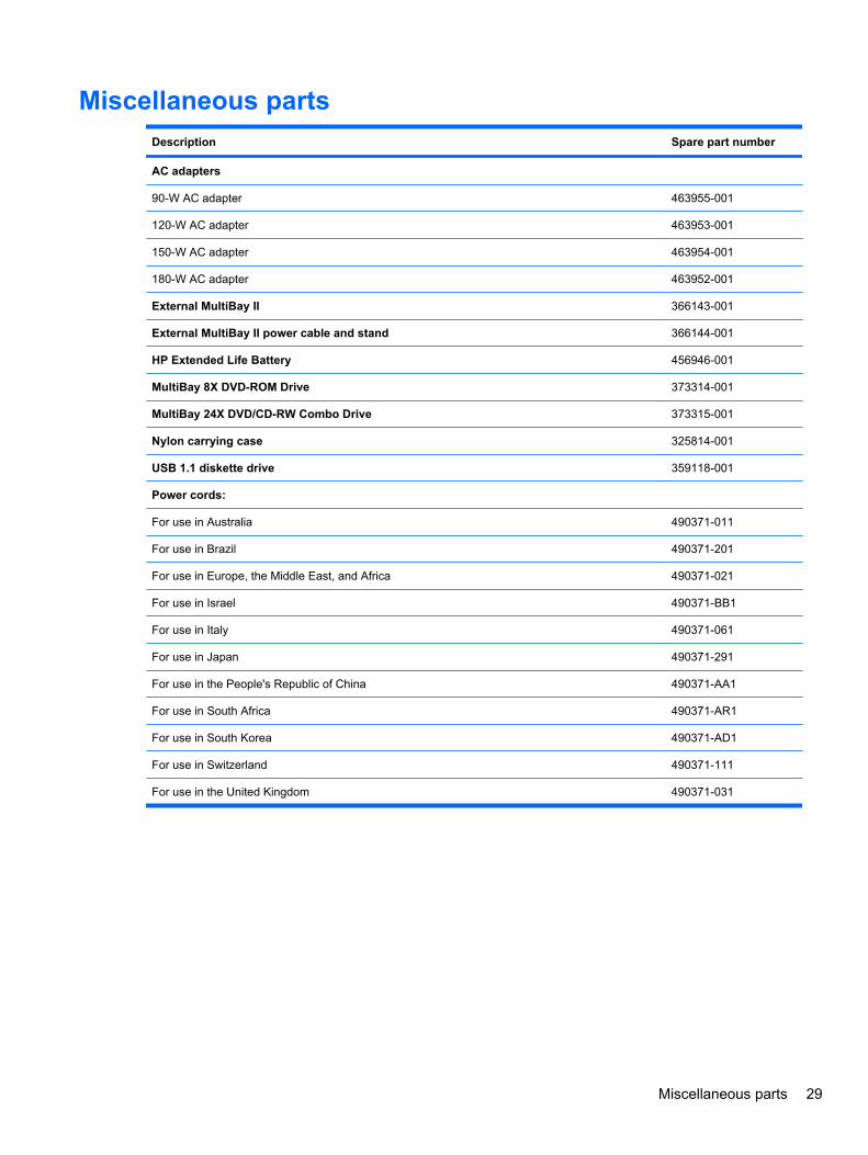
Miscellaneous partsDescription Spare part number
AC adapters
90-W AC adapter 463955-001
120-W AC adapter 463953-001
150-W AC adapter 463954-001
180-W AC adapter 463952-001
External MultiBay II 366143-001
External MultiBay II power cable and stand 366144-001
HP Extended Life Battery 456946-001
MultiBay 8X DVD-ROM Drive 373314-001
MultiBay 24X DVD/CD-RW Combo Drive 373315-001
Nylon carrying case 325814-001
USB 1.1 diskette drive 359118-001
Power cords:
For use in Australia 490371-011
For use in Brazil 490371-201
For use in Europe, the Middle East, and Africa 490371-021
For use in Israel 490371-BB1
For use in Italy 490371-061
For use in Japan 490371-291
For use in the People's Republic of China 490371-AA1
For use in South Africa 490371-AR1
For use in South Korea 490371-AD1
For use in Switzerland 490371-111
For use in the United Kingdom 490371-031
Miscellaneous parts 29
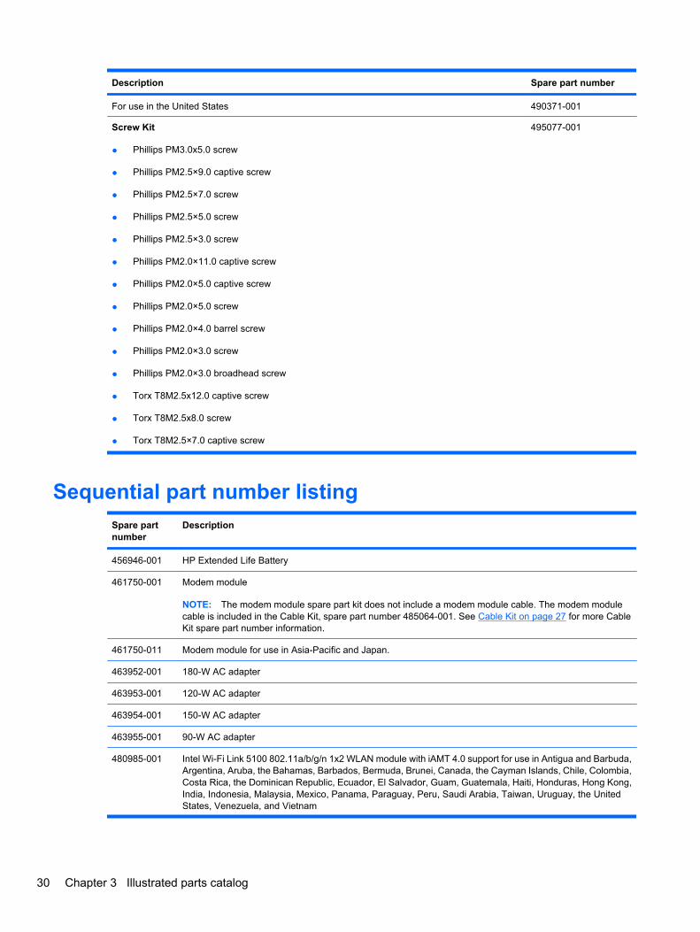
Description Spare part number
For use in the United States 490371-001
Screw Kit
● Phillips PM3.0x5.0 screw
● Phillips PM2.5×9.0 captive screw
● Phillips PM2.5×7.0 screw
● Phillips PM2.5×5.0 screw
● Phillips PM2.5×3.0 screw
● Phillips PM2.0×11.0 captive screw
● Phillips PM2.0×5.0 captive screw
● Phillips PM2.0×5.0 screw
● Phillips PM2.0×4.0 barrel screw
● Phillips PM2.0×3.0 screw
● Phillips PM2.0×3.0 broadhead screw
● Torx T8M2.5x12.0 captive screw
● Torx T8M2.5x8.0 screw
● Torx T8M2.5×7.0 captive screw
495077-001
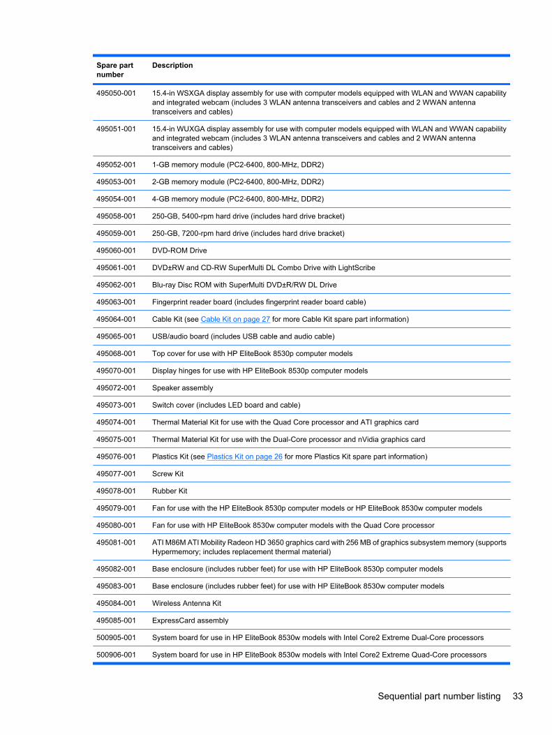
Sequential part number listingSpare partnumber
Description
456946-001 HP Extended Life Battery
461750-001 Modem module
NOTE: The modem module spare part kit does not include a modem module cable. The modem modulecable is included in the Cable Kit, spare part number 485064-001. See Cable Kit on page 27 for more CableKit spare part number information.
461750-011 Modem module for use in Asia-Pacific and Japan.
463952-001 180-W AC adapter
463953-001 120-W AC adapter
463954-001 150-W AC adapter
463955-001 90-W AC adapter
480985-001 Intel Wi-Fi Link 5100 802.11a/b/g/n 1x2 WLAN module with iAMT 4.0 support for use in Antigua and Barbuda,Argentina, Aruba, the Bahamas, Barbados, Bermuda, Brunei, Canada, the Cayman Islands, Chile, Colombia,Costa Rica, the Dominican Republic, Ecuador, El Salvador, Guam, Guatemala, Haiti, Honduras, Hong Kong,India, Indonesia, Malaysia, Mexico, Panama, Paraguay, Peru, Saudi Arabia, Taiwan, Uruguay, the UnitedStates, Venezuela, and Vietnam
30 Chapter 3 Illustrated parts catalog
Spare partnumber
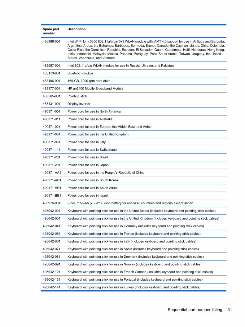
Description
480986-001 Intel Wi-Fi Link 5300 802.11a/b/g/n 3x3 WLAN module with iAMT 4.0 support for use in Antigua and Barbuda,Argentina, Aruba, the Bahamas, Barbados, Bermuda, Brunei, Canada, the Cayman Islands, Chile, Colombia,Costa Rica, the Dominican Republic, Ecuador, El Salvador, Guam, Guatemala, Haiti, Honduras, Hong Kong,India, Indonesia, Malaysia, Mexico, Panama, Paraguay, Peru, Saudi Arabia, Taiwan, Uruguay, the UnitedStates, Venezuela, and Vietnam
482957-001 Intel 802.11a/b/g WLAN module for use in Russia, Ukraine, and Pakistan
483113-001 Bluetooth module
483186-001 160-GB, 7200-rpm hard drive
483377-001 HP un2400 Mobile Broadband Module
486565-001 Pointing stick
487431-001 Display inverter
490371-001 Power cord for use in North America
490371-011 Power cord for use in Australia
490371-021 Power cord for use in Europe, the Middle East, and Africa
490371-031 Power cord for use in the United Kingdom
490371-061 Power cord for use in Italy
490371-111 Power cord for use in Switzerland
490371-201 Power cord for use in Brazil
490371-291 Power cord for use in Japan
490371-AA1 Power cord for use in the People's Republic of China
490371-AD1 Power cord for use in South Korea
490371-AR1 Power cord for use in South Africa
490371-BB1 Power cord for use in Israel
493976-001 8-cell, 2.55-Ah (73-Wh) Li-ion battery for use in all countries and regions except Japan
495042-001 Keyboard with pointing stick for use in the United States (includes keyboard and pointing stick cables)
495042-031 Keyboard with pointing stick for use in the United Kingdom (includes keyboard and pointing stick cables)
495042-041 Keyboard with pointing stick for use in Germany (includes keyboard and pointing stick cables)
495042-051 Keyboard with pointing stick for use in France (includes keyboard and pointing stick cables)
495042-061 Keyboard with pointing stick for use in Italy (includes keyboard and pointing stick cables)
495042-071 Keyboard with pointing stick for use in Spain (includes keyboard and pointing stick cables)
495042-081 Keyboard with pointing stick for use in Denmark (includes keyboard and pointing stick cables)
495042-091 Keyboard with pointing stick for use in Norway (includes keyboard and pointing stick cables)
495042-121 Keyboard with pointing stick for use in French Canada (includes keyboard and pointing stick cables)
495042-131 Keyboard with pointing stick for use in Portugal (includes keyboard and pointing stick cables)
495042-141 Keyboard with pointing stick for use in Turkey (includes keyboard and pointing stick cables)
Sequential part number listing 31
Spare partnumber
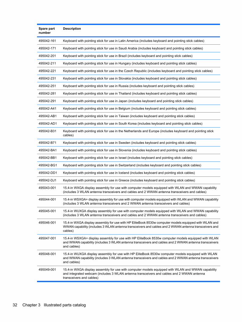
Description
495042-161 Keyboard with pointing stick for use in Latin America (includes keyboard and pointing stick cables)
495042-171 Keyboard with pointing stick for use in Saudi Arabia (includes keyboard and pointing stick cables)
495042-201 Keyboard with pointing stick for use in Brazil (includes keyboard and pointing stick cables)
495042-211 Keyboard with pointing stick for use in Hungary (includes keyboard and pointing stick cables)
495042-221 Keyboard with pointing stick for use in the Czech Republic (includes keyboard and pointing stick cables)
495042-231 Keyboard with pointing stick for use in Slovakia (includes keyboard and pointing stick cables)
495042-251 Keyboard with pointing stick for use in Russia (includes keyboard and pointing stick cables)
495042-281 Keyboard with pointing stick for use in Thailand (includes keyboard and pointing stick cables)
495042-291 Keyboard with pointing stick for use in Japan (includes keyboard and pointing stick cables)
495042-A41 Keyboard with pointing stick for use in Belgium (includes keyboard and pointing stick cables)
495042-AB1 Keyboard with pointing stick for use in Taiwan (includes keyboard and pointing stick cables)
495042-AD1 Keyboard with pointing stick for use in South Korea (includes keyboard and pointing stick cables)
495042-B31 Keyboard with pointing stick for use in the Netherlands and Europe (includes keyboard and pointing stickcables)
495042-B71 Keyboard with pointing stick for use in Sweden (includes keyboard and pointing stick cables)
495042-BA1 Keyboard with pointing stick for use in Slovenia (includes keyboard and pointing stick cables)
495042-BB1 Keyboard with pointing stick for use in Israel (includes keyboard and pointing stick cables)
495042-BG1 Keyboard with pointing stick for use in Switzerland (includes keyboard and pointing stick cables)
495042-DD1 Keyboard with pointing stick for use in Iceland (includes keyboard and pointing stick cables)
495042-DJ1 Keyboard with pointing stick for use in Greece (includes keyboard and pointing stick cables)
495043-001 15.4-in WXGA display assembly for use with computer models equipped with WLAN and WWAN capability(includes 3 WLAN antenna transceivers and cables and 2 WWAN antenna transceivers and cables)
495044-001 15.4-in WSXGA+ display assembly for use with computer models equipped with WLAN and WWAN capability(includes 3 WLAN antenna transceivers and 2 WWAN antenna transceivers and cables)
495045-001 15.4-in WUXGA display assembly for use with computer models equipped with WLAN and WWAN capability(includes 3 WLAN antenna transceivers and cables and 2 WWAN antenna transceivers and cables)
495046-001 15.4-in WXGA display assembly for use with HP EliteBook 8530w computer models equipped with WLAN andWWAN capability (includes 3 WLAN antenna transceivers and cables and 2 WWAN antenna transceivers andcables)
495047-001 15.4-in WSXGA+ display assembly for use with HP EliteBook 8530w computer models equipped with WLANand WWAN capability (includes 3 WLAN antenna transceivers and cables and 2 WWAN antenna transceiversand cables)
495048-001 15.4-in WUXGA display assembly for use with HP EliteBook 8530w computer models equipped with WLANand WWAN capability (includes 3 WLAN antenna transceivers and cables and 2 WWAN antenna transceiversand cables)
495049-001 15.4-in WXGA display assembly for use with computer models equipped with WLAN and WWAN capabilityand integrated webcam (includes 3 WLAN antenna transceivers and cables and 2 WWAN antennatransceivers and cables)
32 Chapter 3 Illustrated parts catalog
Spare partnumber
Description
495050-001 15.4-in WSXGA display assembly for use with computer models equipped with WLAN and WWAN capabilityand integrated webcam (includes 3 WLAN antenna transceivers and cables and 2 WWAN antennatransceivers and cables)
495051-001 15.4-in WUXGA display assembly for use with computer models equipped with WLAN and WWAN capabilityand integrated webcam (includes 3 WLAN antenna transceivers and cables and 2 WWAN antennatransceivers and cables)
495052-001 1-GB memory module (PC2-6400, 800-MHz, DDR2)
495053-001 2-GB memory module (PC2-6400, 800-MHz, DDR2)
495054-001 4-GB memory module (PC2-6400, 800-MHz, DDR2)
495058-001 250-GB, 5400-rpm hard drive (includes hard drive bracket)
495059-001 250-GB, 7200-rpm hard drive (includes hard drive bracket)
495060-001 DVD-ROM Drive
495061-001 DVD±RW and CD-RW SuperMulti DL Combo Drive with LightScribe
495062-001 Blu-ray Disc ROM with SuperMulti DVD±R/RW DL Drive
495063-001 Fingerprint reader board (includes fingerprint reader board cable)
495064-001 Cable Kit (see Cable Kit on page 27 for more Cable Kit spare part information)
495065-001 USB/audio board (includes USB cable and audio cable)
495068-001 Top cover for use with HP EliteBook 8530p computer models
495070-001 Display hinges for use with HP EliteBook 8530p computer models
495072-001 Speaker assembly
495073-001 Switch cover (includes LED board and cable)
495074-001 Thermal Material Kit for use with the Quad Core processor and ATI graphics card
495075-001 Thermal Material Kit for use with the Dual-Core processor and nVidia graphics card
495076-001 Plastics Kit (see Plastics Kit on page 26 for more Plastics Kit spare part information)
495077-001 Screw Kit
495078-001 Rubber Kit
495079-001 Fan for use with the HP EliteBook 8530p computer models or HP EliteBook 8530w computer models
495080-001 Fan for use with HP EliteBook 8530w computer models with the Quad Core processor
495081-001 ATI M86M ATI Mobility Radeon HD 3650 graphics card with 256 MB of graphics subsystem memory (supportsHypermemory; includes replacement thermal material)
495082-001 Base enclosure (includes rubber feet) for use with HP EliteBook 8530p computer models
495083-001 Base enclosure (includes rubber feet) for use with HP EliteBook 8530w computer models
495084-001 Wireless Antenna Kit
495085-001 ExpressCard assembly
500905-001 System board for use in HP EliteBook 8530w models with Intel Core2 Extreme Dual-Core processors
500906-001 System board for use in HP EliteBook 8530w models with Intel Core2 Extreme Quad-Core processors
Sequential part number listing 33
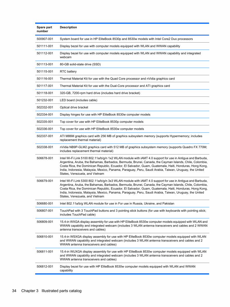
Spare partnumber
Description
500907-001 System board for use in HP EliteBook 8530p and 8530w models with Intel Core2 Duo processors
501111-001 Display bezel for use with computer models equipped with WLAN and WWAN capability
501112-001 Display bezel for use with computer models equipped with WLAN and WWAN capability and integratedwebcam
501113-001 80-GB solid-state drive (SSD)
501115-001 RTC battery
501116-001 Thermal Material Kit for use with the Quad Core processor and nVidia graphics card
501117-001 Thermal Material Kit for use with the Dual-Core processor and ATI graphics card
501118-001 320-GB, 7200-rpm hard drive (includes hard drive bracket)
501232-001 LED board (includes cable)
502332-001 Optical drive bracket
502334-001 Display hinges for use with HP EliteBook 8530w computer models
502335-001 Top cover for use with HP EliteBook 8530p computer models
502336-001 Top cover for use with HP EliteBook 8530w computer models
502337-001 ATI M86M graphics card with 256 MB of graphics subsystem memory (supports Hypermemory; includesreplacement thermal material)
502338-001 nVidia NB9P-GLM2 graphics card with 512 MB of graphics subsystem memory (supports Quadro FX 770M;includes replacement thermal material)
506678-001 Intel Wi-Fi Link 5100 802.11a/b/g/n 1x2 WLAN module with iAMT 4.0 support for use in Antigua and Barbuda,Argentina, Aruba, the Bahamas, Barbados, Bermuda, Brunei, Canada, the Cayman Islands, Chile, Colombia,Costa Rica, the Dominican Republic, Ecuador, El Salvador, Guam, Guatemala, Haiti, Honduras, Hong Kong,India, Indonesia, Malaysia, Mexico, Panama, Paraguay, Peru, Saudi Arabia, Taiwan, Uruguay, the UnitedStates, Venezuela, and Vietnam
506679-001 Intel Wi-Fi Link 5300 802.11a/b/g/n 3x3 WLAN module with iAMT 4.0 support for use in Antigua and Barbuda,Argentina, Aruba, the Bahamas, Barbados, Bermuda, Brunei, Canada, the Cayman Islands, Chile, Colombia,Costa Rica, the Dominican Republic, Ecuador, El Salvador, Guam, Guatemala, Haiti, Honduras, Hong Kong,India, Indonesia, Malaysia, Mexico, Panama, Paraguay, Peru, Saudi Arabia, Taiwan, Uruguay, the UnitedStates, Venezuela, and Vietnam
506680-001 Intel 802.11a/b/g WLAN module for use in For use in Russia, Ukraine, and Pakistan
506807-001 TouchPad with 3 TouchPad buttons and 3 pointing stick buttons (for use with keyboards with pointing stick;includes TouchPad cable)
506809-001 15.4-in WXGA display assembly for use with HP EliteBook 8530w computer models equipped with WLAN andWWAN capability and integrated webcam (includes 3 WLAN antenna transceivers and cables and 2 WWANantenna transceivers and cables)
506810-001 15.4-in WSXGA display assembly for use with HP EliteBook 8530w computer models equipped with WLANand WWAN capability and integrated webcam (includes 3 WLAN antenna transceivers and cables and 2WWAN antenna transceivers and cables)
506811-001 15.4-in WUXGA display assembly for use with HP EliteBook 8530w computer models equipped with WLANand WWAN capability and integrated webcam (includes 3 WLAN antenna transceivers and cables and 2WWAN antenna transceivers and cables)
506812-001 Display bezel for use with HP EliteBook 8530w computer models equipped with WLAN and WWANcapability
34 Chapter 3 Illustrated parts catalog
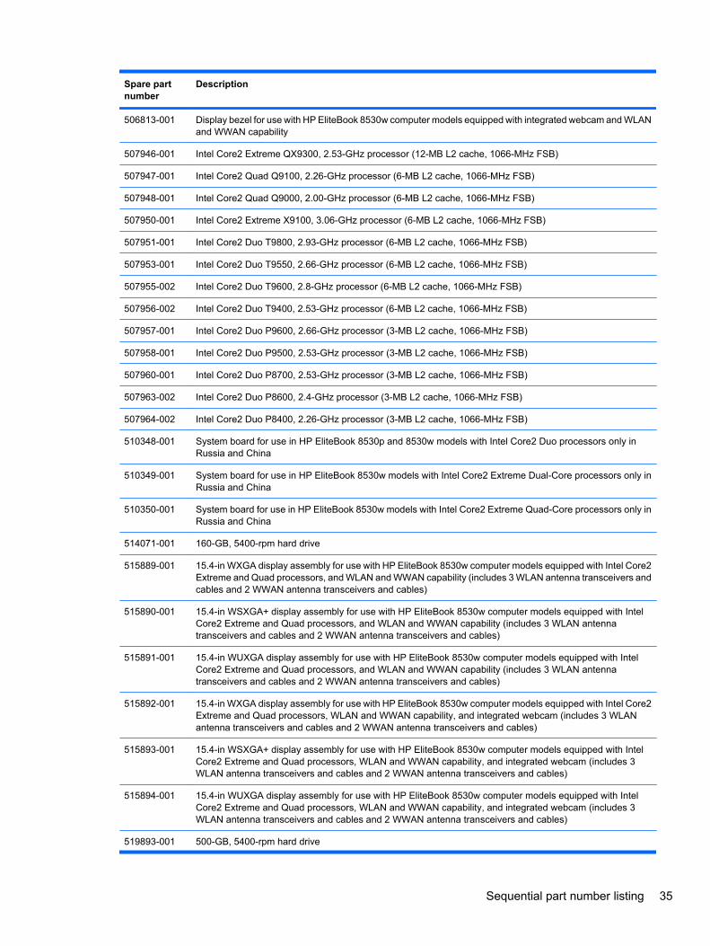
Spare partnumber
Description
506813-001 Display bezel for use with HP EliteBook 8530w computer models equipped with integrated webcam and WLANand WWAN capability
507946-001 Intel Core2 Extreme QX9300, 2.53-GHz processor (12-MB L2 cache, 1066-MHz FSB)
507947-001 Intel Core2 Quad Q9100, 2.26-GHz processor (6-MB L2 cache, 1066-MHz FSB)
507948-001 Intel Core2 Quad Q9000, 2.00-GHz processor (6-MB L2 cache, 1066-MHz FSB)
507950-001 Intel Core2 Extreme X9100, 3.06-GHz processor (6-MB L2 cache, 1066-MHz FSB)
507951-001 Intel Core2 Duo T9800, 2.93-GHz processor (6-MB L2 cache, 1066-MHz FSB)
507953-001 Intel Core2 Duo T9550, 2.66-GHz processor (6-MB L2 cache, 1066-MHz FSB)
507955-002 Intel Core2 Duo T9600, 2.8-GHz processor (6-MB L2 cache, 1066-MHz FSB)
507956-002 Intel Core2 Duo T9400, 2.53-GHz processor (6-MB L2 cache, 1066-MHz FSB)
507957-001 Intel Core2 Duo P9600, 2.66-GHz processor (3-MB L2 cache, 1066-MHz FSB)
507958-001 Intel Core2 Duo P9500, 2.53-GHz processor (3-MB L2 cache, 1066-MHz FSB)
507960-001 Intel Core2 Duo P8700, 2.53-GHz processor (3-MB L2 cache, 1066-MHz FSB)
507963-002 Intel Core2 Duo P8600, 2.4-GHz processor (3-MB L2 cache, 1066-MHz FSB)
507964-002 Intel Core2 Duo P8400, 2.26-GHz processor (3-MB L2 cache, 1066-MHz FSB)
510348-001 System board for use in HP EliteBook 8530p and 8530w models with Intel Core2 Duo processors only inRussia and China
510349-001 System board for use in HP EliteBook 8530w models with Intel Core2 Extreme Dual-Core processors only inRussia and China
510350-001 System board for use in HP EliteBook 8530w models with Intel Core2 Extreme Quad-Core processors only inRussia and China
514071-001 160-GB, 5400-rpm hard drive
515889-001 15.4-in WXGA display assembly for use with HP EliteBook 8530w computer models equipped with Intel Core2Extreme and Quad processors, and WLAN and WWAN capability (includes 3 WLAN antenna transceivers andcables and 2 WWAN antenna transceivers and cables)
515890-001 15.4-in WSXGA+ display assembly for use with HP EliteBook 8530w computer models equipped with IntelCore2 Extreme and Quad processors, and WLAN and WWAN capability (includes 3 WLAN antennatransceivers and cables and 2 WWAN antenna transceivers and cables)
515891-001 15.4-in WUXGA display assembly for use with HP EliteBook 8530w computer models equipped with IntelCore2 Extreme and Quad processors, and WLAN and WWAN capability (includes 3 WLAN antennatransceivers and cables and 2 WWAN antenna transceivers and cables)
515892-001 15.4-in WXGA display assembly for use with HP EliteBook 8530w computer models equipped with Intel Core2Extreme and Quad processors, WLAN and WWAN capability, and integrated webcam (includes 3 WLANantenna transceivers and cables and 2 WWAN antenna transceivers and cables)
515893-001 15.4-in WSXGA+ display assembly for use with HP EliteBook 8530w computer models equipped with IntelCore2 Extreme and Quad processors, WLAN and WWAN capability, and integrated webcam (includes 3WLAN antenna transceivers and cables and 2 WWAN antenna transceivers and cables)
515894-001 15.4-in WUXGA display assembly for use with HP EliteBook 8530w computer models equipped with IntelCore2 Extreme and Quad processors, WLAN and WWAN capability, and integrated webcam (includes 3WLAN antenna transceivers and cables and 2 WWAN antenna transceivers and cables)
519893-001 500-GB, 5400-rpm hard drive
Sequential part number listing 35
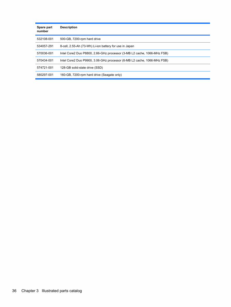
Spare partnumber
Description
532108-001 500-GB, 7200-rpm hard drive
534057-291 8-cell, 2.55-Ah (73-Wh) Li-ion battery for use in Japan
570036-001 Intel Core2 Duo P8800, 2.66-GHz processor (3-MB L2 cache, 1066-MHz FSB)
570434-001 Intel Core2 Duo P9900, 3.06-GHz processor (6-MB L2 cache, 1066-MHz FSB)
574721-001 128-GB solid-state drive (SSD)
580297-001 160-GB, 7200-rpm hard drive (Seagate only)
36 Chapter 3 Illustrated parts catalog
4 Removal and replacement procedures
Preliminary replacement requirementsTools required
You will need the following tools to complete the removal and replacement procedures:
● Flat-bladed screwdriver
● Phillips P0 and P1 screwdrivers
● Torx T8 screwdriver
Service considerationsThe following sections include some of the considerations that you must keep in mind duringdisassembly and assembly procedures.
NOTE: As you remove each subassembly from the computer, place the subassembly (and allaccompanying screws) away from the work area to prevent damage.
Plastic partsCAUTION: Using excessive force during disassembly and reassembly can damage plastic parts. Usecare when handling the plastic parts. Apply pressure only at the points designated in the maintenanceinstructions.
Preliminary replacement requirements 37
Cables and connectorsCAUTION: When servicing the computer, be sure that cables are placed in their proper locationsduring the reassembly process. Improper cable placement can damage the computer.
Cables must be handled with extreme care to avoid damage. Apply only the tension required to unseator seat the cables during removal and insertion. Handle cables by the connector whenever possible. Inall cases, avoid bending, twisting, or tearing cables. Be sure that cables are routed in such a way thatthey cannot be caught or snagged by parts being removed or replaced. Handle flex cables with extremecare; these cables tear easily.
Drive handlingCAUTION: Drives are fragile components that must be handled with care. To prevent damage to thecomputer, damage to a drive, or loss of information, observe these precautions:
Before removing or inserting a hard drive, shut down the computer. If you are unsure whether thecomputer is off or in Hibernation, turn the computer on, and then shut it down through the operatingsystem.
Before handling a drive, be sure that you are discharged of static electricity. While handling a drive,avoid touching the connector.
Before removing a diskette drive or optical drive, be sure that a diskette or disc is not in the drive andbe sure that the optical drive tray is closed.
Handle drives on surfaces covered with at least one inch of shock-proof foam.
Avoid dropping drives from any height onto any surface.
After removing a hard drive, an optical drive, or a diskette drive, place it in a static-proof bag.
Avoid exposing a hard drive to products that have magnetic fields, such as monitors or speakers.
Avoid exposing a drive to temperature extremes or liquids.
If a drive must be mailed, place the drive in a bubble pack mailer or other suitable form of protectivepackaging and label the package “FRAGILE.”
38 Chapter 4 Removal and replacement procedures
Grounding guidelines
Electrostatic discharge damageElectronic components are sensitive to electrostatic discharge (ESD). Circuitry design and structuredetermine the degree of sensitivity. Networks built into many integrated circuits provide some protection,but in many cases, ESD contains enough power to alter device parameters or melt silicon junctions.
A discharge of static electricity from a finger or other conductor can destroy static-sensitive devices ormicrocircuitry. Even if the spark is neither felt nor heard, damage may have occurred.
An electronic device exposed to ESD may not be affected at all and can work perfectly throughout anormal cycle. Or the device may function normally for a while, then degrade in the internal layers,reducing its life expectancy.
CAUTION: To prevent damage to the computer when you are removing or installing internalcomponents, observe these precautions:
Keep components in their electrostatic-safe containers until you are ready to install them.
Use nonmagnetic tools.
Before touching an electronic component, discharge static electricity by using the guidelines describedin this section.
Avoid touching pins, leads, and circuitry. Handle electronic components as little as possible.
If you remove a component, place it in an electrostatic-safe container.
The following table shows how humidity affects the electrostatic voltage levels generated by differentactivities.
CAUTION: A product can be degraded by as little as 700 V.
Typical electrostatic voltage levels
Relative humidity
Event 10% 40% 55%
Walking across carpet 35,000 V 15,000 V 7,500 V
Walking across vinyl floor 12,000 V 5,000 V 3,000 V
Motions of bench worker 6,000 V 800 V 400 V
Removing DIPS from plastic tube 2,000 V 700 V 400 V
Removing DIPS from vinyl tray 11,500 V 4,000 V 2,000 V
Removing DIPS from Styrofoam 14,500 V 5,000 V 3,500 V
Removing bubble pack from PCB 26,500 V 20,000 V 7,000 V
Packing PCBs in foam-lined box 21,000 V 11,000 V 5,000 V
Preliminary replacement requirements 39
Packaging and transporting guidelines
Follow these grounding guidelines when packaging and transporting equipment:
● To avoid hand contact, transport products in static-safe tubes, bags, or boxes.
● Protect ESD-sensitive parts and assemblies with conductive or approved containers or packaging.
● Keep ESD-sensitive parts in their containers until the parts arrive at static-free workstations.
● Place items on a grounded surface before removing items from their containers.
● Always be properly grounded when touching a component or assembly.
● Store reusable ESD-sensitive parts from assemblies in protective packaging or nonconductivefoam.
● Use transporters and conveyors made of antistatic belts and roller bushings. Be sure thatmechanized equipment used for moving materials is wired to ground and that proper materials areselected to avoid static charging. When grounding is not possible, use an ionizer to dissipateelectric charges.
Workstation guidelines
Follow these grounding workstation guidelines:
● Cover the workstation with approved static-shielding material.
● Use a wrist strap connected to a properly grounded work surface and use properly grounded toolsand equipment.
● Use conductive field service tools, such as cutters, screwdrivers, and vacuums.
● When fixtures must directly contact dissipative surfaces, use fixtures made only of static-safematerials.
● Keep the work area free of nonconductive materials, such as ordinary plastic assembly aids andStyrofoam.
● Handle ESD-sensitive components, parts, and assemblies by the case or PCM laminate. Handlethese items only at static-free workstations.
● Avoid contact with pins, leads, or circuitry.
● Turn off power and input signals before inserting or removing connectors or test equipment.
40 Chapter 4 Removal and replacement procedures
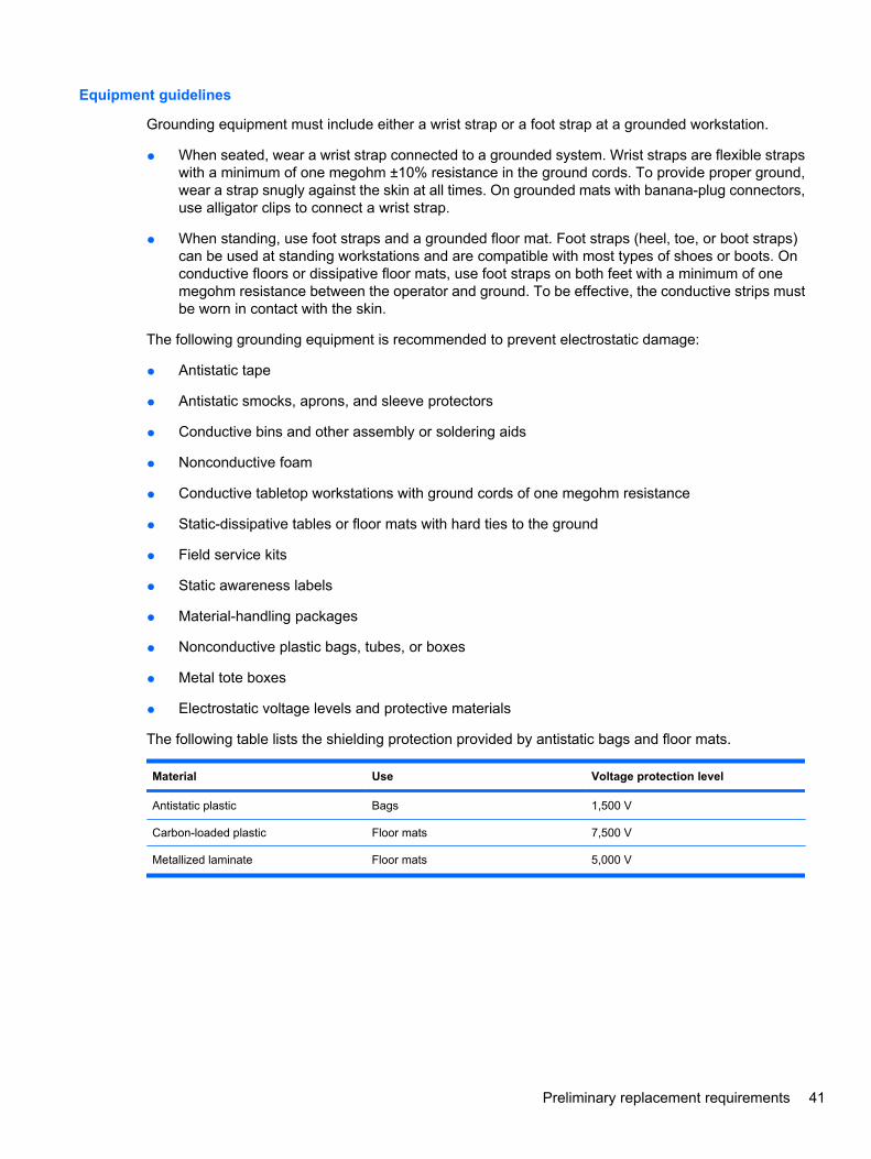
Equipment guidelines
Grounding equipment must include either a wrist strap or a foot strap at a grounded workstation.
● When seated, wear a wrist strap connected to a grounded system. Wrist straps are flexible strapswith a minimum of one megohm ±10% resistance in the ground cords. To provide proper ground,wear a strap snugly against the skin at all times. On grounded mats with banana-plug connectors,use alligator clips to connect a wrist strap.
● When standing, use foot straps and a grounded floor mat. Foot straps (heel, toe, or boot straps)can be used at standing workstations and are compatible with most types of shoes or boots. Onconductive floors or dissipative floor mats, use foot straps on both feet with a minimum of onemegohm resistance between the operator and ground. To be effective, the conductive strips mustbe worn in contact with the skin.
The following grounding equipment is recommended to prevent electrostatic damage:
● Antistatic tape
● Antistatic smocks, aprons, and sleeve protectors
● Conductive bins and other assembly or soldering aids
● Nonconductive foam
● Conductive tabletop workstations with ground cords of one megohm resistance
● Static-dissipative tables or floor mats with hard ties to the ground
● Field service kits
● Static awareness labels
● Material-handling packages
● Nonconductive plastic bags, tubes, or boxes
● Metal tote boxes
● Electrostatic voltage levels and protective materials
The following table lists the shielding protection provided by antistatic bags and floor mats.
Material Use Voltage protection level
Antistatic plastic Bags 1,500 V
Carbon-loaded plastic Floor mats 7,500 V
Metallized laminate Floor mats 5,000 V
Preliminary replacement requirements 41

Component replacement proceduresThis chapter provides removal and replacement procedures.
There are as many as 97 screws and screw locks, in 17 different sizes, that must be removed, replaced,or loosened when servicing the computer. Make special note of each screw and screw lock size andlocation during removal and replacement.
Service tagWhen ordering parts or requesting information, provide the computer serial number and modeldescription provided on the service tag.
● Product name (1). This is the product name affixed to the front of the computer.
● Serial number (s/n) (2). This is an alphanumeric identifier that is unique to each product.
● Part number/Product number (p/n) (3). This number provides specific information about theproduct's hardware components. The part number helps a service technician to determine whatcomponents and parts are needed.
● Model description (4). This is the alphanumeric identifier used to locate documents, drivers, andsupport for the computer.
● Warranty period (5). This number describes the duration (in years) of the warranty period for thecomputer.
42 Chapter 4 Removal and replacement procedures
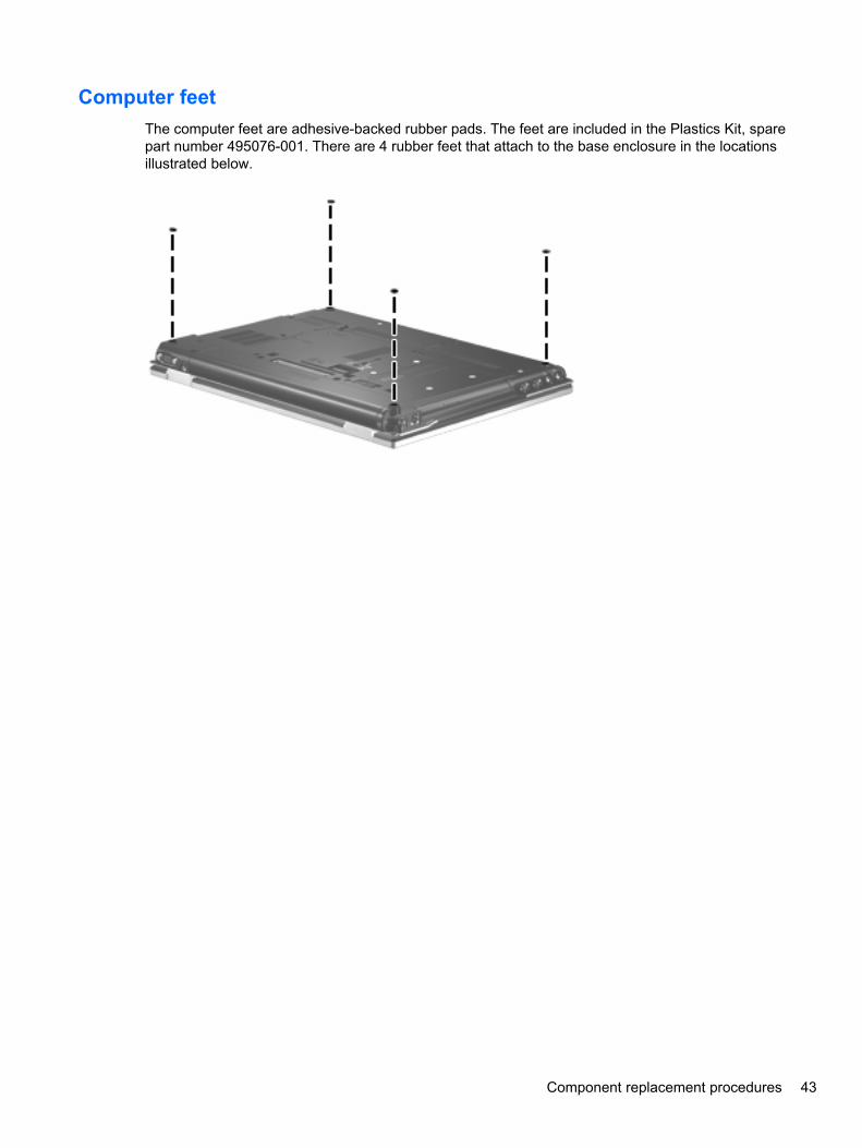
Computer feetThe computer feet are adhesive-backed rubber pads. The feet are included in the Plastics Kit, sparepart number 495076-001. There are 4 rubber feet that attach to the base enclosure in the locationsillustrated below.
Component replacement procedures 43
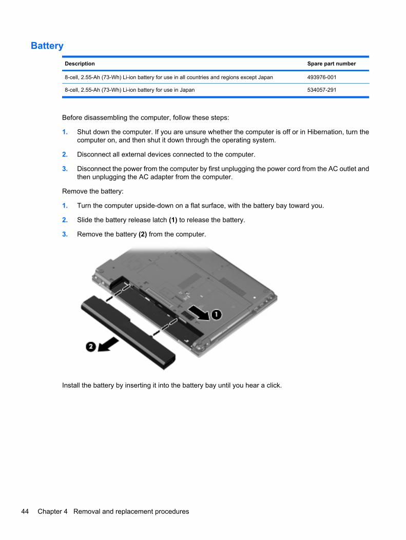
Battery
Description Spare part number
8-cell, 2.55-Ah (73-Wh) Li-ion battery for use in all countries and regions except Japan 493976-001
8-cell, 2.55-Ah (73-Wh) Li-ion battery for use in Japan 534057-291
Before disassembling the computer, follow these steps:
1. Shut down the computer. If you are unsure whether the computer is off or in Hibernation, turn thecomputer on, and then shut it down through the operating system.
2. Disconnect all external devices connected to the computer.
3. Disconnect the power from the computer by first unplugging the power cord from the AC outlet andthen unplugging the AC adapter from the computer.
Remove the battery:
1. Turn the computer upside-down on a flat surface, with the battery bay toward you.
2. Slide the battery release latch (1) to release the battery.
3. Remove the battery (2) from the computer.
Install the battery by inserting it into the battery bay until you hear a click.
44 Chapter 4 Removal and replacement procedures
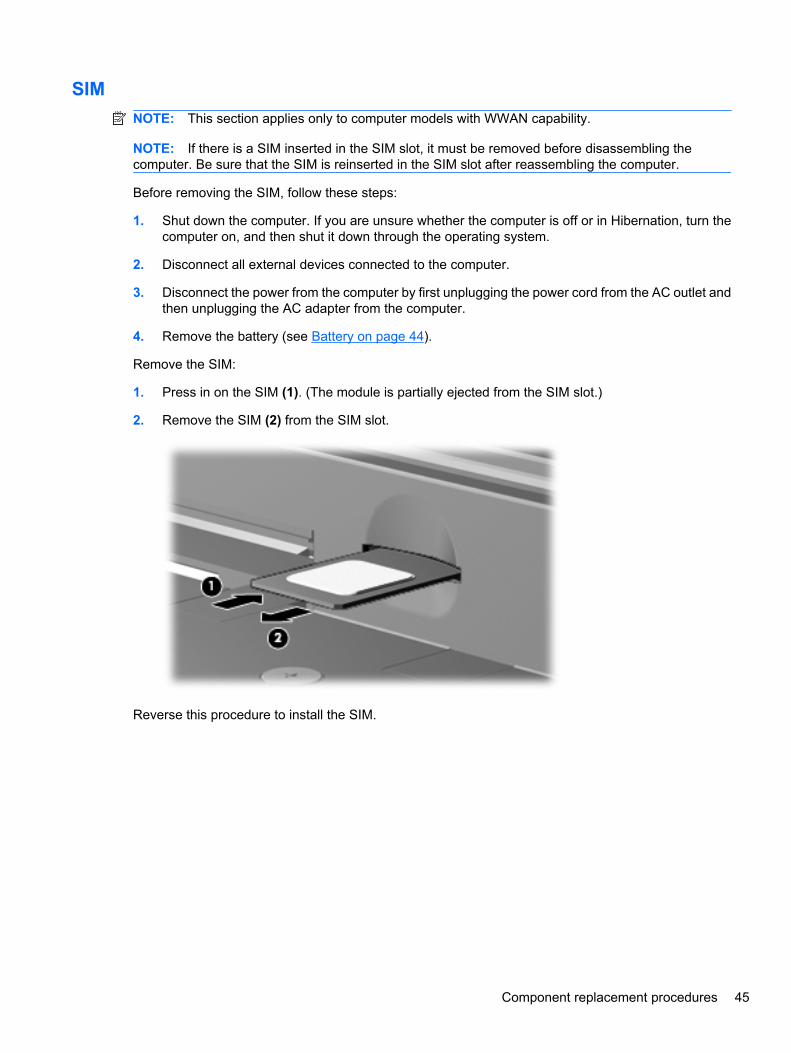
SIMNOTE: This section applies only to computer models with WWAN capability.
NOTE: If there is a SIM inserted in the SIM slot, it must be removed before disassembling thecomputer. Be sure that the SIM is reinserted in the SIM slot after reassembling the computer.
Before removing the SIM, follow these steps:
1. Shut down the computer. If you are unsure whether the computer is off or in Hibernation, turn thecomputer on, and then shut it down through the operating system.
2. Disconnect all external devices connected to the computer.
3. Disconnect the power from the computer by first unplugging the power cord from the AC outlet andthen unplugging the AC adapter from the computer.
4. Remove the battery (see Battery on page 44).
Remove the SIM:
1. Press in on the SIM (1). (The module is partially ejected from the SIM slot.)
2. Remove the SIM (2) from the SIM slot.
Reverse this procedure to install the SIM.
Component replacement procedures 45
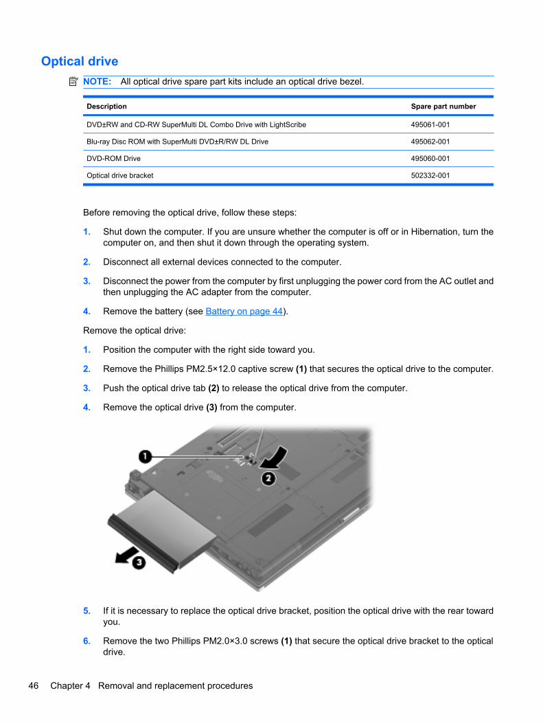
Optical driveNOTE: All optical drive spare part kits include an optical drive bezel.
Description Spare part number
DVD±RW and CD-RW SuperMulti DL Combo Drive with LightScribe 495061-001
Blu-ray Disc ROM with SuperMulti DVD±R/RW DL Drive 495062-001
DVD-ROM Drive 495060-001
Optical drive bracket 502332-001
Before removing the optical drive, follow these steps:
1. Shut down the computer. If you are unsure whether the computer is off or in Hibernation, turn thecomputer on, and then shut it down through the operating system.
2. Disconnect all external devices connected to the computer.
3. Disconnect the power from the computer by first unplugging the power cord from the AC outlet andthen unplugging the AC adapter from the computer.
4. Remove the battery (see Battery on page 44).
Remove the optical drive:
1. Position the computer with the right side toward you.
2. Remove the Phillips PM2.5×12.0 captive screw (1) that secures the optical drive to the computer.
3. Push the optical drive tab (2) to release the optical drive from the computer.
4. Remove the optical drive (3) from the computer.
5. If it is necessary to replace the optical drive bracket, position the optical drive with the rear towardyou.
6. Remove the two Phillips PM2.0×3.0 screws (1) that secure the optical drive bracket to the opticaldrive.
46 Chapter 4 Removal and replacement procedures
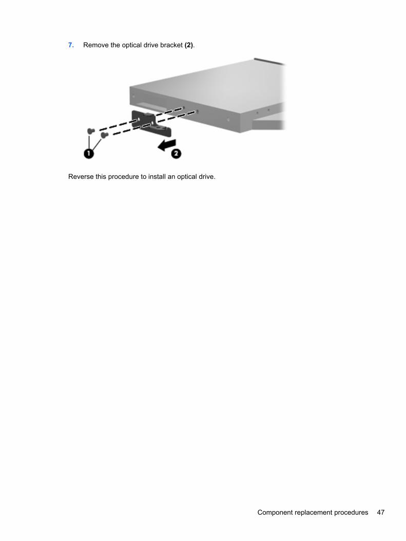
7. Remove the optical drive bracket (2).
Reverse this procedure to install an optical drive.
Component replacement procedures 47
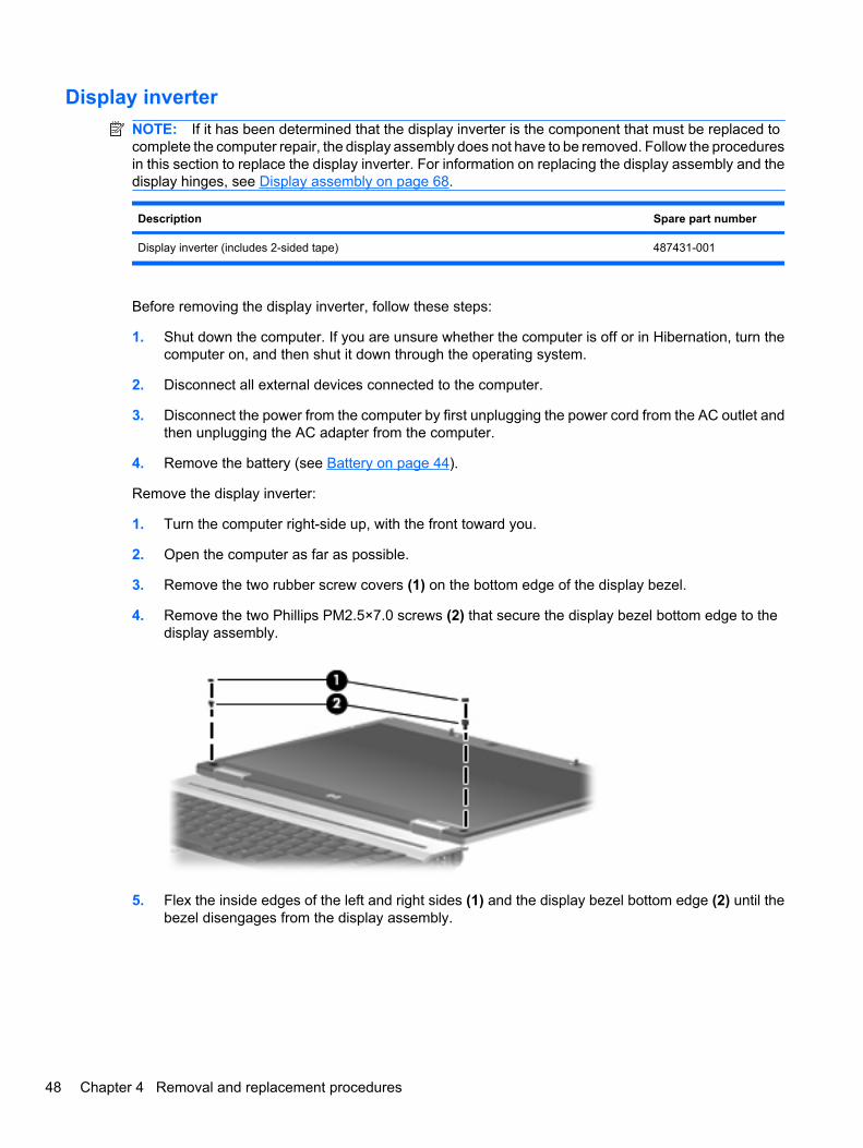
Display inverterNOTE: If it has been determined that the display inverter is the component that must be replaced tocomplete the computer repair, the display assembly does not have to be removed. Follow the proceduresin this section to replace the display inverter. For information on replacing the display assembly and thedisplay hinges, see Display assembly on page 68.
Description Spare part number
Display inverter (includes 2-sided tape) 487431-001
Before removing the display inverter, follow these steps:
1. Shut down the computer. If you are unsure whether the computer is off or in Hibernation, turn thecomputer on, and then shut it down through the operating system.
2. Disconnect all external devices connected to the computer.
3. Disconnect the power from the computer by first unplugging the power cord from the AC outlet andthen unplugging the AC adapter from the computer.
4. Remove the battery (see Battery on page 44).
Remove the display inverter:
1. Turn the computer right-side up, with the front toward you.
2. Open the computer as far as possible.
3. Remove the two rubber screw covers (1) on the bottom edge of the display bezel.
4. Remove the two Phillips PM2.5×7.0 screws (2) that secure the display bezel bottom edge to thedisplay assembly.
5. Flex the inside edges of the left and right sides (1) and the display bezel bottom edge (2) until thebezel disengages from the display assembly.
48 Chapter 4 Removal and replacement procedures
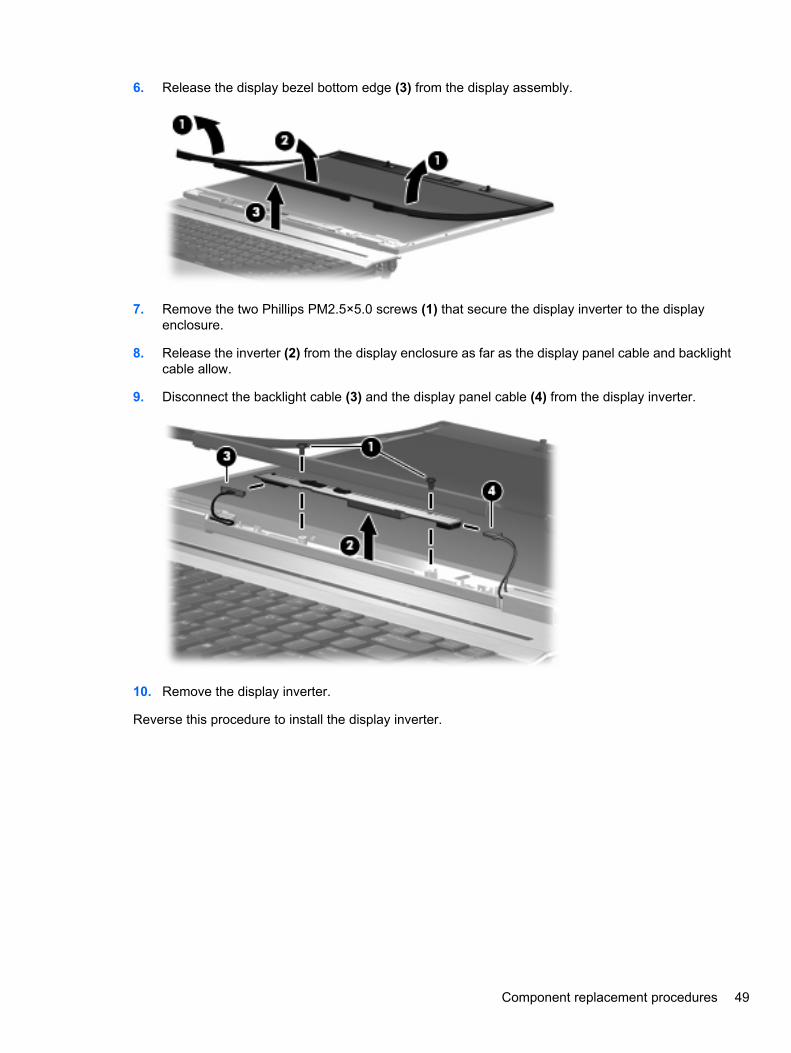
6. Release the display bezel bottom edge (3) from the display assembly.
7. Remove the two Phillips PM2.5×5.0 screws (1) that secure the display inverter to the displayenclosure.
8. Release the inverter (2) from the display enclosure as far as the display panel cable and backlightcable allow.
9. Disconnect the backlight cable (3) and the display panel cable (4) from the display inverter.
10. Remove the display inverter.
Reverse this procedure to install the display inverter.
Component replacement procedures 49
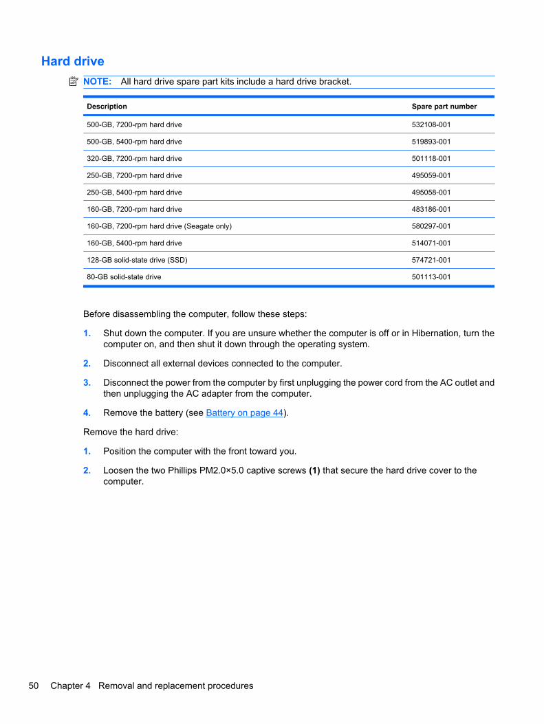
Hard driveNOTE: All hard drive spare part kits include a hard drive bracket.
Description Spare part number
500-GB, 7200-rpm hard drive 532108-001
500-GB, 5400-rpm hard drive 519893-001
320-GB, 7200-rpm hard drive 501118-001
250-GB, 7200-rpm hard drive 495059-001
250-GB, 5400-rpm hard drive 495058-001
160-GB, 7200-rpm hard drive 483186-001
160-GB, 7200-rpm hard drive (Seagate only) 580297-001
160-GB, 5400-rpm hard drive 514071-001
128-GB solid-state drive (SSD) 574721-001
80-GB solid-state drive 501113-001
Before disassembling the computer, follow these steps:
1. Shut down the computer. If you are unsure whether the computer is off or in Hibernation, turn thecomputer on, and then shut it down through the operating system.
2. Disconnect all external devices connected to the computer.
3. Disconnect the power from the computer by first unplugging the power cord from the AC outlet andthen unplugging the AC adapter from the computer.
4. Remove the battery (see Battery on page 44).
Remove the hard drive:
1. Position the computer with the front toward you.
2. Loosen the two Phillips PM2.0×5.0 captive screws (1) that secure the hard drive cover to thecomputer.
50 Chapter 4 Removal and replacement procedures
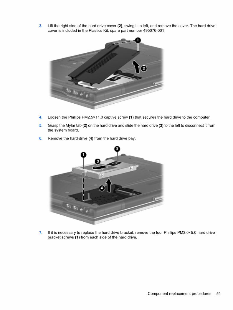
3. Lift the right side of the hard drive cover (2), swing it to left, and remove the cover. The hard drivecover is included in the Plastics Kit, spare part number 495076-001
4. Loosen the Phillips PM2.5×11.0 captive screw (1) that secures the hard drive to the computer.
5. Grasp the Mylar tab (2) on the hard drive and slide the hard drive (3) to the left to disconnect it fromthe system board.
6. Remove the hard drive (4) from the hard drive bay.
7. If it is necessary to replace the hard drive bracket, remove the four Phillips PM3.0×5.0 hard drivebracket screws (1) from each side of the hard drive.
Component replacement procedures 51
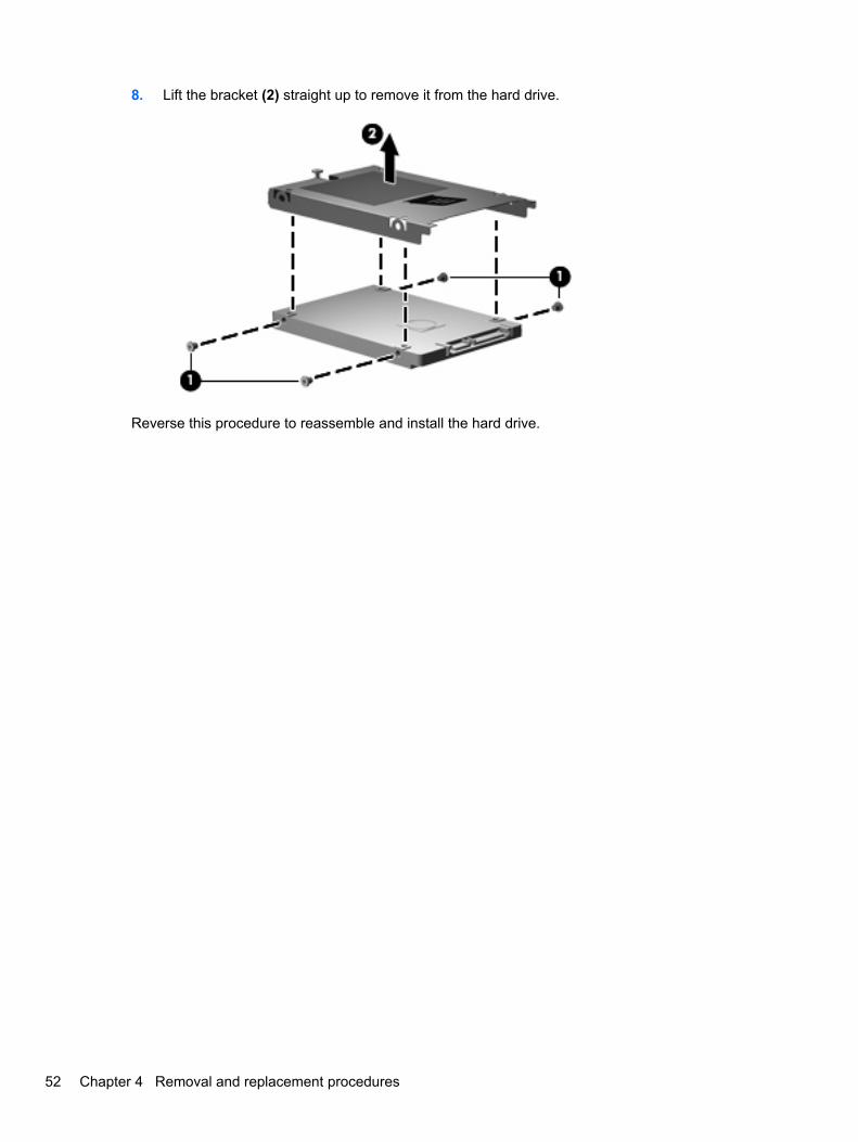
8. Lift the bracket (2) straight up to remove it from the hard drive.
Reverse this procedure to reassemble and install the hard drive.
52 Chapter 4 Removal and replacement procedures
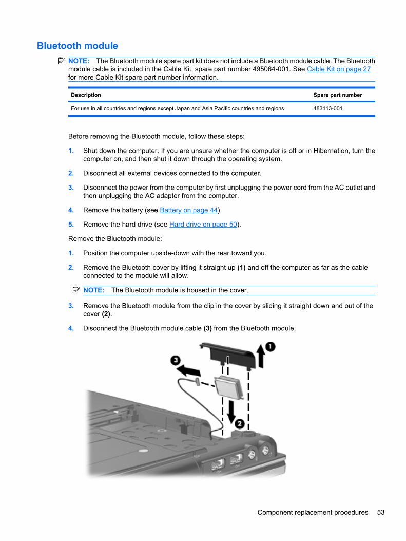
Bluetooth moduleNOTE: The Bluetooth module spare part kit does not include a Bluetooth module cable. The Bluetoothmodule cable is included in the Cable Kit, spare part number 495064-001. See Cable Kit on page 27for more Cable Kit spare part number information.
Description Spare part number
For use in all countries and regions except Japan and Asia Pacific countries and regions 483113-001
Before removing the Bluetooth module, follow these steps:
1. Shut down the computer. If you are unsure whether the computer is off or in Hibernation, turn thecomputer on, and then shut it down through the operating system.
2. Disconnect all external devices connected to the computer.
3. Disconnect the power from the computer by first unplugging the power cord from the AC outlet andthen unplugging the AC adapter from the computer.
4. Remove the battery (see Battery on page 44).
5. Remove the hard drive (see Hard drive on page 50).
Remove the Bluetooth module:
1. Position the computer upside-down with the rear toward you.
2. Remove the Bluetooth cover by lifting it straight up (1) and off the computer as far as the cableconnected to the module will allow.
NOTE: The Bluetooth module is housed in the cover.
3. Remove the Bluetooth module from the clip in the cover by sliding it straight down and out of thecover (2).
4. Disconnect the Bluetooth module cable (3) from the Bluetooth module.
Component replacement procedures 53
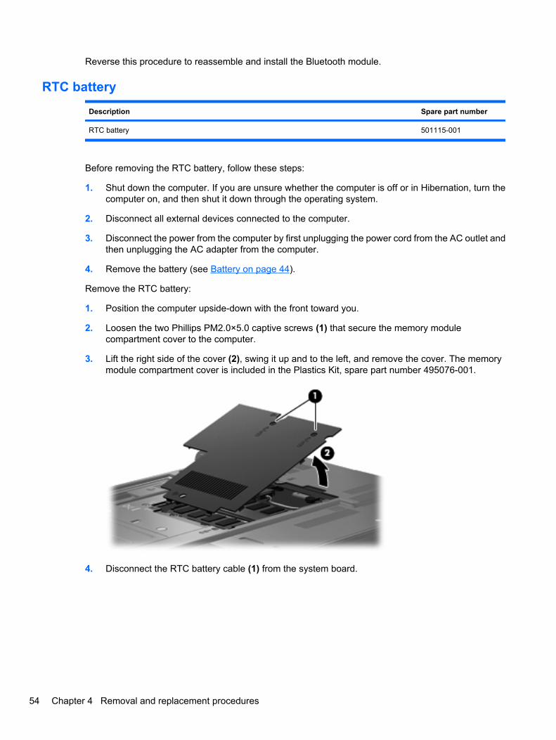
Reverse this procedure to reassemble and install the Bluetooth module.
RTC battery
Description Spare part number
RTC battery 501115-001
Before removing the RTC battery, follow these steps:
1. Shut down the computer. If you are unsure whether the computer is off or in Hibernation, turn thecomputer on, and then shut it down through the operating system.
2. Disconnect all external devices connected to the computer.
3. Disconnect the power from the computer by first unplugging the power cord from the AC outlet andthen unplugging the AC adapter from the computer.
4. Remove the battery (see Battery on page 44).
Remove the RTC battery:
1. Position the computer upside-down with the front toward you.
2. Loosen the two Phillips PM2.0×5.0 captive screws (1) that secure the memory modulecompartment cover to the computer.
3. Lift the right side of the cover (2), swing it up and to the left, and remove the cover. The memorymodule compartment cover is included in the Plastics Kit, spare part number 495076-001.
4. Disconnect the RTC battery cable (1) from the system board.
54 Chapter 4 Removal and replacement procedures
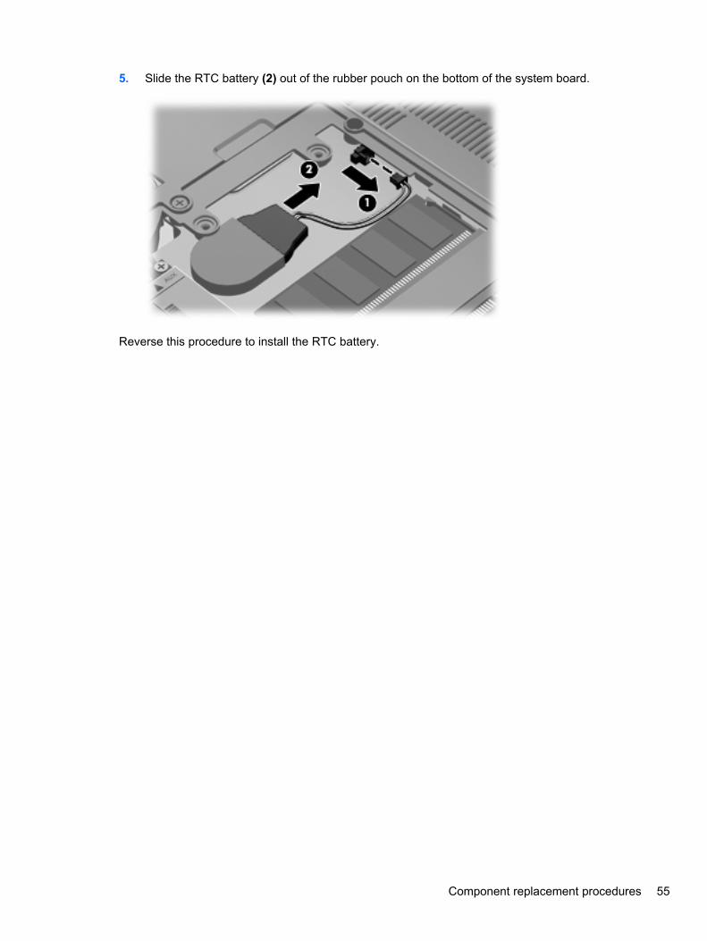
5. Slide the RTC battery (2) out of the rubber pouch on the bottom of the system board.
Reverse this procedure to install the RTC battery.
Component replacement procedures 55
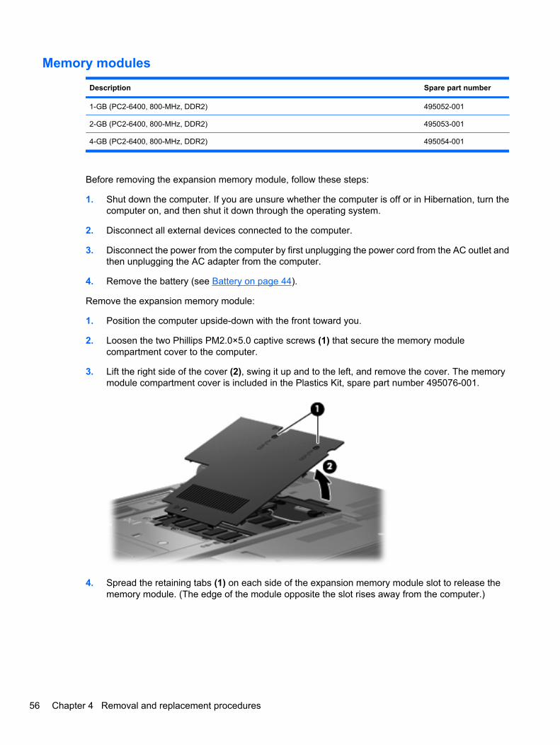
Memory modules
Description Spare part number
1-GB (PC2-6400, 800-MHz, DDR2) 495052-001
2-GB (PC2-6400, 800-MHz, DDR2) 495053-001
4-GB (PC2-6400, 800-MHz, DDR2) 495054-001
Before removing the expansion memory module, follow these steps:
1. Shut down the computer. If you are unsure whether the computer is off or in Hibernation, turn thecomputer on, and then shut it down through the operating system.
2. Disconnect all external devices connected to the computer.
3. Disconnect the power from the computer by first unplugging the power cord from the AC outlet andthen unplugging the AC adapter from the computer.
4. Remove the battery (see Battery on page 44).
Remove the expansion memory module:
1. Position the computer upside-down with the front toward you.
2. Loosen the two Phillips PM2.0×5.0 captive screws (1) that secure the memory modulecompartment cover to the computer.
3. Lift the right side of the cover (2), swing it up and to the left, and remove the cover. The memorymodule compartment cover is included in the Plastics Kit, spare part number 495076-001.
4. Spread the retaining tabs (1) on each side of the expansion memory module slot to release thememory module. (The edge of the module opposite the slot rises away from the computer.)
56 Chapter 4 Removal and replacement procedures
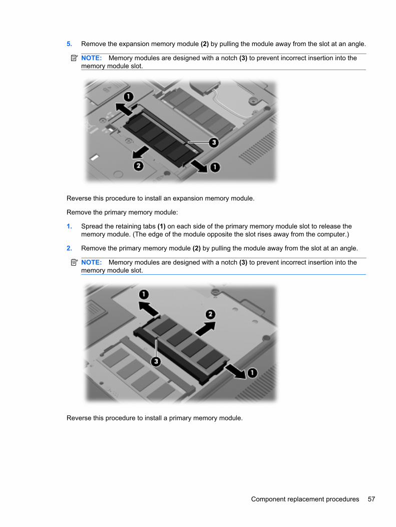
5. Remove the expansion memory module (2) by pulling the module away from the slot at an angle.
NOTE: Memory modules are designed with a notch (3) to prevent incorrect insertion into thememory module slot.
Reverse this procedure to install an expansion memory module.
Remove the primary memory module:
1. Spread the retaining tabs (1) on each side of the primary memory module slot to release thememory module. (The edge of the module opposite the slot rises away from the computer.)
2. Remove the primary memory module (2) by pulling the module away from the slot at an angle.
NOTE: Memory modules are designed with a notch (3) to prevent incorrect insertion into thememory module slot.
Reverse this procedure to install a primary memory module.
Component replacement procedures 57
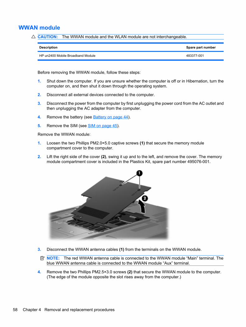
WWAN moduleCAUTION: The WWAN module and the WLAN module are not interchangeable.
Description Spare part number
HP un2400 Mobile Broadband Module 483377-001
Before removing the WWAN module, follow these steps:
1. Shut down the computer. If you are unsure whether the computer is off or in Hibernation, turn thecomputer on, and then shut it down through the operating system.
2. Disconnect all external devices connected to the computer.
3. Disconnect the power from the computer by first unplugging the power cord from the AC outlet andthen unplugging the AC adapter from the computer.
4. Remove the battery (see Battery on page 44).
5. Remove the SIM (see SIM on page 45).
Remove the WWAN module:
1. Loosen the two Phillips PM2.0×5.0 captive screws (1) that secure the memory modulecompartment cover to the computer.
2. Lift the right side of the cover (2), swing it up and to the left, and remove the cover. The memorymodule compartment cover is included in the Plastics Kit, spare part number 495076-001.
3. Disconnect the WWAN antenna cables (1) from the terminals on the WWAN module.
NOTE: The red WWAN antenna cable is connected to the WWAN module “Main” terminal. Theblue WWAN antenna cable is connected to the WWAN module “Aux” terminal.
4. Remove the two Phillips PM2.5×3.0 screws (2) that secure the WWAN module to the computer.(The edge of the module opposite the slot rises away from the computer.)
58 Chapter 4 Removal and replacement procedures
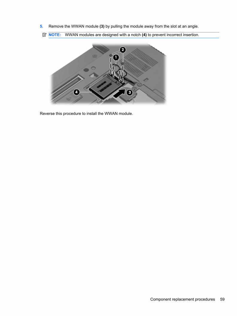
5. Remove the WWAN module (3) by pulling the module away from the slot at an angle.
NOTE: WWAN modules are designed with a notch (4) to prevent incorrect insertion.
Reverse this procedure to install the WWAN module.
Component replacement procedures 59
Keyboard
For use in: Spare part number For use in: Spare part number
Keyboards with pointing stick (includes pointing stick cable):
Belgium
Brazil
The Czech Republic
Denmark
France
French Canada
Germany
Greece
Hungary
Iceland
Israel
Italy
Japan
South Korea
Latin America
495042-A41
495042-201
495042-221
495042-081
495042-051
495042-121
495042-041
495042-DJ1
495042-211
495042-DD1
495042-BB1
495042-061
495042-291
495042-AD1
495042-161
The Netherlands and Europe
Norway
Portugal
Russia
Saudi Arabia
Slovakia
Slovenia
Spain
Sweden and Finland
Switzerland
Taiwan
Thailand
Turkey
The United Kingdom
The United States
495042-B31
495042-091
495042-131
495042-251
495042-171
495042-231
495042-BA1
495042-071
495042-B71
495042-BG1
495042-AB1
495042-281
495042-141
495042-031
495042-001
Before removing the keyboard, follow these steps:
1. Shut down the computer. If you are unsure whether the computer is off or in Hibernation, turn thecomputer on, and then shut it down through the operating system.
2. Disconnect all external devices connected to the computer.
3. Disconnect the power from the computer by first unplugging the power cord from the AC outlet andthen unplugging the AC adapter from the computer.
4. Remove the battery (see Battery on page 44).
Remove the keyboard:
1. Turn the computer upside-down, with the rear toward you.
60 Chapter 4 Removal and replacement procedures
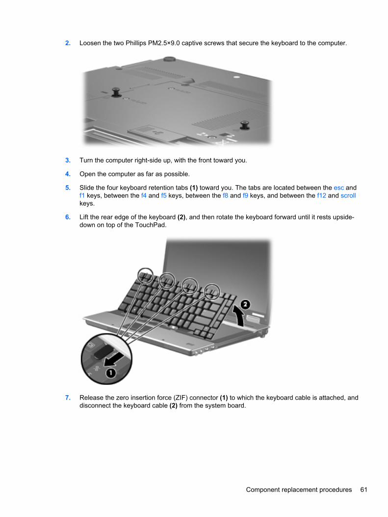
2. Loosen the two Phillips PM2.5×9.0 captive screws that secure the keyboard to the computer.
3. Turn the computer right-side up, with the front toward you.
4. Open the computer as far as possible.
5. Slide the four keyboard retention tabs (1) toward you. The tabs are located between the esc andf1 keys, between the f4 and f5 keys, between the f8 and f9 keys, and between the f12 and scrollkeys.
6. Lift the rear edge of the keyboard (2), and then rotate the keyboard forward until it rests upside-down on top of the TouchPad.
7. Release the zero insertion force (ZIF) connector (1) to which the keyboard cable is attached, anddisconnect the keyboard cable (2) from the system board.
Component replacement procedures 61
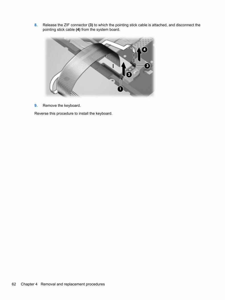
8. Release the ZIF connector (3) to which the pointing stick cable is attached, and disconnect thepointing stick cable (4) from the system board.
9. Remove the keyboard.
Reverse this procedure to install the keyboard.
62 Chapter 4 Removal and replacement procedures
Modem moduleNOTE: The modem module spare part kit does not include a modem module cable. The modemmodule cable is included in the Cable Kit, spare part number 495064-001. See Cable Kit on page 27for more Cable Kit spare part number information.
Description Spare part number
Modem module 461750-001
Modem module for use in Asia Pacific and Japan 461750-011
Before removing the modem module, follow these steps:
1. Shut down the computer. If you are unsure whether the computer is off or in Hibernation, turn thecomputer on, and then shut it down through the operating system.
2. Disconnect all external devices connected to the computer.
3. Disconnect the power from the computer by first unplugging the power cord from the AC outlet andthen unplugging the AC adapter from the computer.
4. Remove the battery (see Battery on page 44).
5. Remove the following components:
a. Hard drive (see Hard drive on page 50)
b. Optical drive (see Optical drive on page 46)
c. Keyboard (see Keyboard on page 60)
Remove the modem module:
1. Turn the computer right-side up, with the front toward you.
2. Remove the Phillips PM2.0×4.0 barrel screws (1) that secure the modem module to the systemboard.
3. Disconnect the modem module (2) from the system board by lifting it straight up.
Component replacement procedures 63

4. Disconnect the modem module cable (3) from the modem module.
Reverse this procedure to install the modem module.
WLAN moduleCAUTION: The WLAN module and the WWAN module are not interchangeable.
Description Spare part number
Intel Wi-Fi Link 5100 802.11a/b/g/n 1x2 WLAN module with iAMT 4.0 support:
● For use in Antigua and Barbuda, Argentina, Aruba, the Bahamas, Barbados, Bermuda, Brunei,Canada, the Cayman Islands, Chile, Colombia, Costa Rica, the Dominican Republic, Ecuador,El Salvador, Guam, Guatemala, Haiti, Honduras, Hong Kong, India, Indonesia, Malaysia,Mexico, Panama, Paraguay, Peru, Saudi Arabia, Taiwan, Uruguay, the United States,Venezuela, and Vietnam
480985-001 or506678-001
Intel Wi-Fi Link 5300 802.11a/b/g/n 3x3 WLAN module with iAMT 4.0 support:
● For use in Antigua and Barbuda, Argentina, Aruba, the Bahamas, Barbados, Bermuda, Brunei,Canada, the Cayman Islands, Chile, Colombia, Costa Rica, the Dominican Republic, Ecuador,El Salvador, Guam, Guatemala, Haiti, Honduras, Hong Kong, India, Indonesia, Malaysia,Mexico, Panama, Paraguay, Peru, Saudi Arabia, Taiwan, Uruguay, the United States,Venezuela, and Vietnam
480986-001 or506679-001
Intel Wi-Fi Link 5100 802.11 a/b/g 1x2 WLAN Module with iAMT 4.0 support:
● For use in Russia, Ukraine, and Pakistan 482957-001 or506808-001
Before removing the WLAN module, follow these steps:
1. Shut down the computer. If you are unsure whether the computer is off or in Hibernation, turn thecomputer on, and then shut it down through the operating system.
2. Disconnect all external devices connected to the computer.
3. Disconnect the power from the computer by first unplugging the power cord from the AC outlet andthen unplugging the AC adapter from the computer.
64 Chapter 4 Removal and replacement procedures
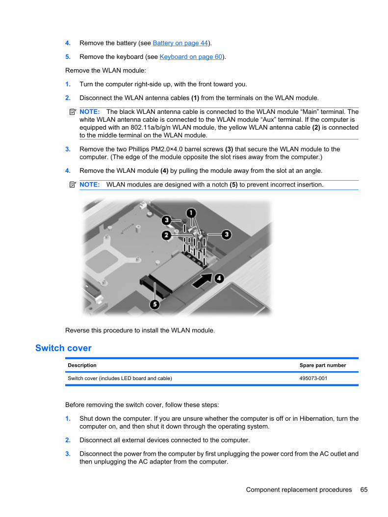
4. Remove the battery (see Battery on page 44).
5. Remove the keyboard (see Keyboard on page 60).
Remove the WLAN module:
1. Turn the computer right-side up, with the front toward you.
2. Disconnect the WLAN antenna cables (1) from the terminals on the WLAN module.
NOTE: The black WLAN antenna cable is connected to the WLAN module “Main” terminal. Thewhite WLAN antenna cable is connected to the WLAN module “Aux” terminal. If the computer isequipped with an 802.11a/b/g/n WLAN module, the yellow WLAN antenna cable (2) is connectedto the middle terminal on the WLAN module.
3. Remove the two Phillips PM2.0×4.0 barrel screws (3) that secure the WLAN module to thecomputer. (The edge of the module opposite the slot rises away from the computer.)
4. Remove the WLAN module (4) by pulling the module away from the slot at an angle.
NOTE: WLAN modules are designed with a notch (5) to prevent incorrect insertion.
Reverse this procedure to install the WLAN module.
Switch cover
Description Spare part number
Switch cover (includes LED board and cable) 495073-001
Before removing the switch cover, follow these steps:
1. Shut down the computer. If you are unsure whether the computer is off or in Hibernation, turn thecomputer on, and then shut it down through the operating system.
2. Disconnect all external devices connected to the computer.
3. Disconnect the power from the computer by first unplugging the power cord from the AC outlet andthen unplugging the AC adapter from the computer.
Component replacement procedures 65
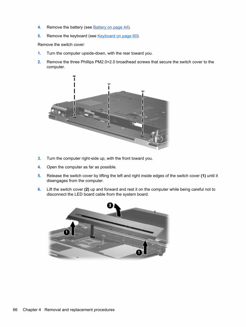
4. Remove the battery (see Battery on page 44).
5. Remove the keyboard (see Keyboard on page 60).
Remove the switch cover:
1. Turn the computer upside-down, with the rear toward you.
2. Remove the three Phillips PM2.0×2.0 broadhead screws that secure the switch cover to thecomputer.
3. Turn the computer right-side up, with the front toward you.
4. Open the computer as far as possible.
5. Release the switch cover by lifting the left and right inside edges of the switch cover (1) until itdisengages from the computer.
6. Lift the switch cover (2) up and forward and rest it on the computer while being careful not todisconnect the LED board cable from the system board.
66 Chapter 4 Removal and replacement procedures
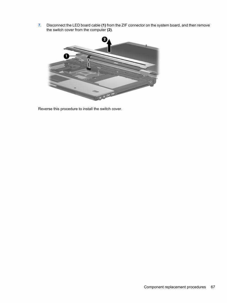
7. Disconnect the LED board cable (1) from the ZIF connector on the system board, and then removethe switch cover from the computer (2).
Reverse this procedure to install the switch cover.
Component replacement procedures 67
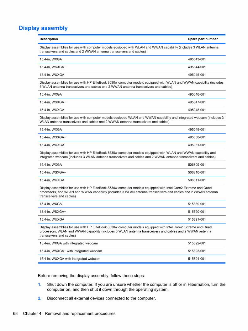
Display assembly
Description Spare part number
Display assemblies for use with computer models equipped with WLAN and WWAN capability (includes 3 WLAN antennatransceivers and cables and 2 WWAN antenna transceivers and cables)
15.4-in, WXGA 495043-001
15.4-in, WSXGA+ 495044-001
15.4-in, WUXGA 495045-001
Display assemblies for use with HP EliteBook 8530w computer models equipped with WLAN and WWAN capability (includes3 WLAN antenna transceivers and cables and 2 WWAN antenna transceivers and cables)
15.4-in, WXGA 495046-001
15.4-in, WSXGA+ 495047-001
15.4-in, WUXGA 495048-001
Display assemblies for use with computer models equipped WLAN and WWAN capability and integrated webcam (includes 3WLAN antenna transceivers and cables and 2 WWAN antenna transceivers and cables)
15.4-in, WXGA 495049-001
15.4-in, WSXGA+ 495050-001
15.4-in, WUXGA 495051-001
Display assemblies for use with HP EliteBook 8530w computer models equipped with WLAN and WWAN capability andintegrated webcam (includes 3 WLAN antenna transceivers and cables and 2 WWAN antenna transceivers and cables)
15.4-in, WXGA 506809-001
15.4-in, WSXGA+ 506810-001
15.4-in, WUXGA 506811-001
Display assemblies for use with HP EliteBook 8530w computer models equipped with Intel Core2 Extreme and Quadprocessors, and WLAN and WWAN capability (includes 3 WLAN antenna transceivers and cables and 2 WWAN antennatransceivers and cables)
15.4-in, WXGA 515889-001
15.4-in, WSXGA+ 515890-001
15.4-in, WUXGA 515891-001
Display assemblies for use with HP EliteBook 8530w computer models equipped with Intel Core2 Extreme and Quadprocessors, WLAN and WWAN capability (includes 3 WLAN antenna transceivers and cables and 2 WWAN antennatransceivers and cables)
15.4-in, WXGA with integrated webcam 515892-001
15.4-in, WSXGA+ with integrated webcam 515893-001
15.4-in, WUXGA with integrated webcam 515894-001
Before removing the display assembly, follow these steps:
1. Shut down the computer. If you are unsure whether the computer is off or in Hibernation, turn thecomputer on, and then shut it down through the operating system.
2. Disconnect all external devices connected to the computer.
68 Chapter 4 Removal and replacement procedures
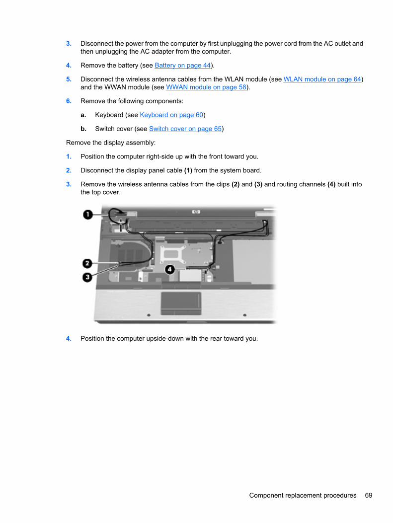
3. Disconnect the power from the computer by first unplugging the power cord from the AC outlet andthen unplugging the AC adapter from the computer.
4. Remove the battery (see Battery on page 44).
5. Disconnect the wireless antenna cables from the WLAN module (see WLAN module on page 64)and the WWAN module (see WWAN module on page 58).
6. Remove the following components:
a. Keyboard (see Keyboard on page 60)
b. Switch cover (see Switch cover on page 65)
Remove the display assembly:
1. Position the computer right-side up with the front toward you.
2. Disconnect the display panel cable (1) from the system board.
3. Remove the wireless antenna cables from the clips (2) and (3) and routing channels (4) built intothe top cover.
4. Position the computer upside-down with the rear toward you.
Component replacement procedures 69
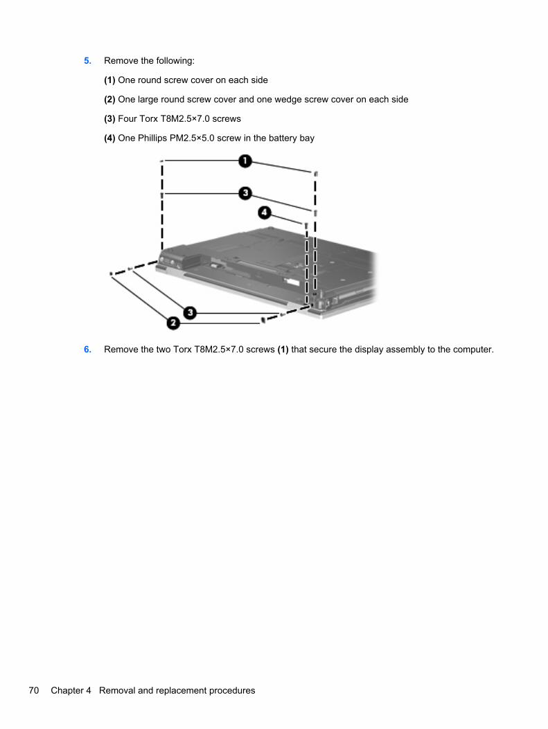
5. Remove the following:
(1) One round screw cover on each side
(2) One large round screw cover and one wedge screw cover on each side
(3) Four Torx T8M2.5×7.0 screws
(4) One Phillips PM2.5×5.0 screw in the battery bay
6. Remove the two Torx T8M2.5×7.0 screws (1) that secure the display assembly to the computer.
70 Chapter 4 Removal and replacement procedures
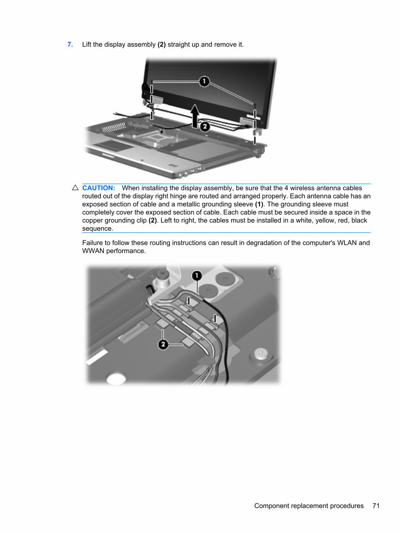
7. Lift the display assembly (2) straight up and remove it.
CAUTION: When installing the display assembly, be sure that the 4 wireless antenna cablesrouted out of the display right hinge are routed and arranged properly. Each antenna cable has anexposed section of cable and a metallic grounding sleeve (1). The grounding sleeve mustcompletely cover the exposed section of cable. Each cable must be secured inside a space in thecopper grounding clip (2). Left to right, the cables must be installed in a white, yellow, red, blacksequence.
Failure to follow these routing instructions can result in degradation of the computer's WLAN andWWAN performance.
Component replacement procedures 71
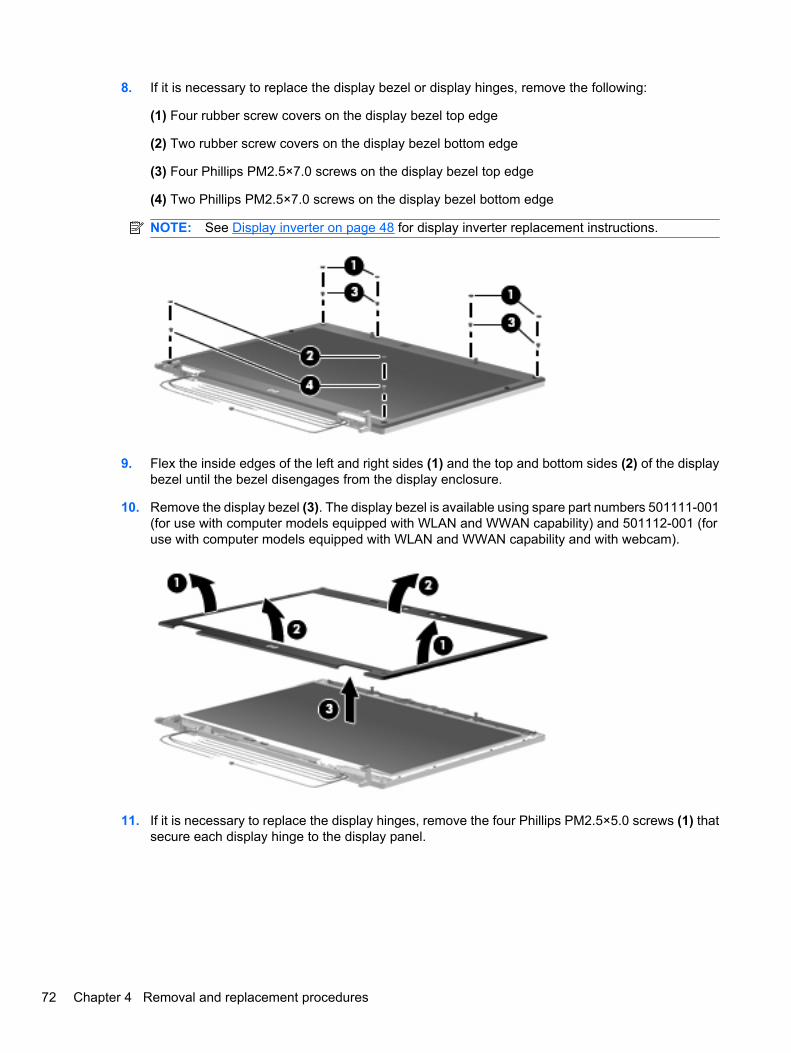
8. If it is necessary to replace the display bezel or display hinges, remove the following:
(1) Four rubber screw covers on the display bezel top edge
(2) Two rubber screw covers on the display bezel bottom edge
(3) Four Phillips PM2.5×7.0 screws on the display bezel top edge
(4) Two Phillips PM2.5×7.0 screws on the display bezel bottom edge
NOTE: See Display inverter on page 48 for display inverter replacement instructions.
9. Flex the inside edges of the left and right sides (1) and the top and bottom sides (2) of the displaybezel until the bezel disengages from the display enclosure.
10. Remove the display bezel (3). The display bezel is available using spare part numbers 501111-001(for use with computer models equipped with WLAN and WWAN capability) and 501112-001 (foruse with computer models equipped with WLAN and WWAN capability and with webcam).
11. If it is necessary to replace the display hinges, remove the four Phillips PM2.5×5.0 screws (1) thatsecure each display hinge to the display panel.
72 Chapter 4 Removal and replacement procedures
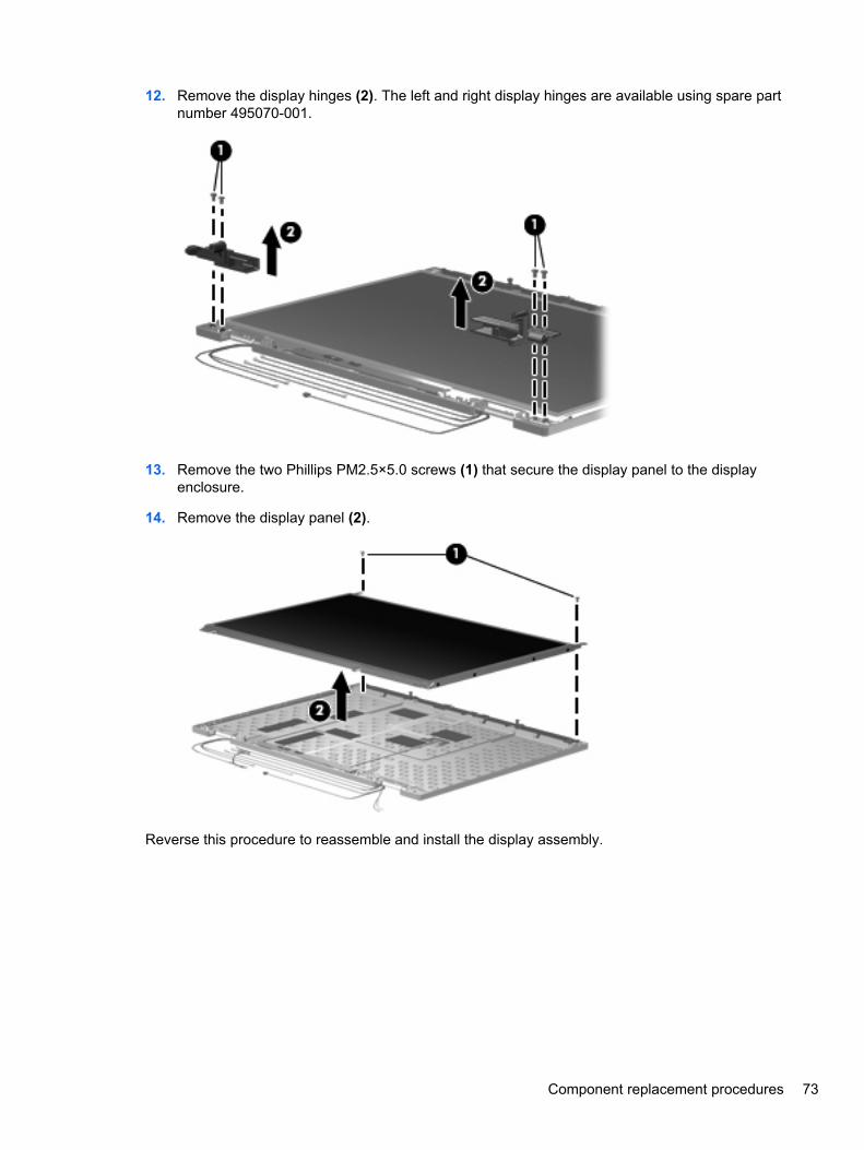
12. Remove the display hinges (2). The left and right display hinges are available using spare partnumber 495070-001.
13. Remove the two Phillips PM2.5×5.0 screws (1) that secure the display panel to the displayenclosure.
14. Remove the display panel (2).
Reverse this procedure to reassemble and install the display assembly.
Component replacement procedures 73
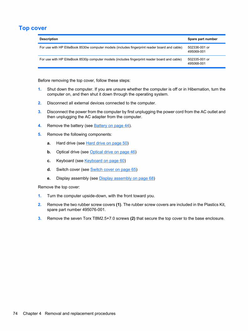
Top cover
Description Spare part number
For use with HP EliteBook 8530w computer models (includes fingerprint reader board and cable) 502336-001 or495069-001
For use with HP EliteBook 8530p computer models (includes fingerprint reader board and cable) 502335-001 or495068-001
Before removing the top cover, follow these steps:
1. Shut down the computer. If you are unsure whether the computer is off or in Hibernation, turn thecomputer on, and then shut it down through the operating system.
2. Disconnect all external devices connected to the computer.
3. Disconnect the power from the computer by first unplugging the power cord from the AC outlet andthen unplugging the AC adapter from the computer.
4. Remove the battery (see Battery on page 44).
5. Remove the following components:
a. Hard drive (see Hard drive on page 50)
b. Optical drive (see Optical drive on page 46)
c. Keyboard (see Keyboard on page 60)
d. Switch cover (see Switch cover on page 65)
e. Display assembly (see Display assembly on page 68)
Remove the top cover:
1. Turn the computer upside-down, with the front toward you.
2. Remove the two rubber screw covers (1). The rubber screw covers are included in the Plastics Kit,spare part number 495076-001.
3. Remove the seven Torx T8M2.5×7.0 screws (2) that secure the top cover to the base enclosure.
74 Chapter 4 Removal and replacement procedures
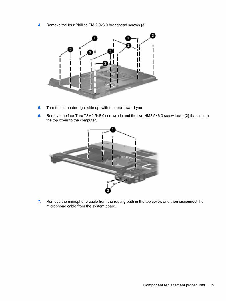
4. Remove the four Phillips PM 2.0x3.0 broadhead screws (3)
5. Turn the computer right-side up, with the rear toward you.
6. Remove the four Torx T8M2.5×8.0 screws (1) and the two HM2.5×6.0 screw locks (2) that securethe top cover to the computer.
7. Remove the microphone cable from the routing path in the top cover, and then disconnect themicrophone cable from the system board.
Component replacement procedures 75
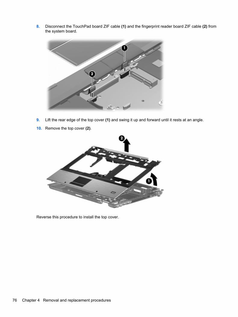
8. Disconnect the TouchPad board ZIF cable (1) and the fingerprint reader board ZIF cable (2) fromthe system board.
9. Lift the rear edge of the top cover (1) and swing it up and forward until it rests at an angle.
10. Remove the top cover (2).
Reverse this procedure to install the top cover.
76 Chapter 4 Removal and replacement procedures
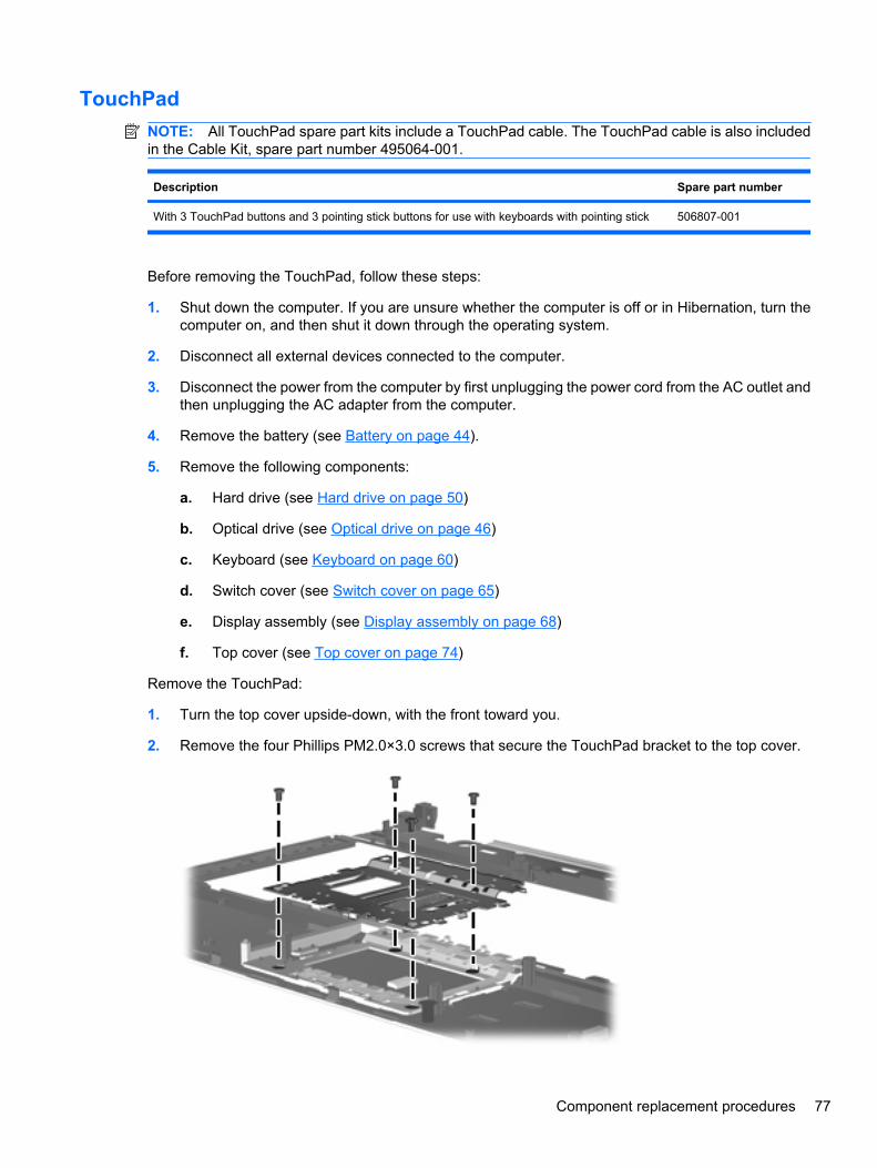
TouchPadNOTE: All TouchPad spare part kits include a TouchPad cable. The TouchPad cable is also includedin the Cable Kit, spare part number 495064-001.
Description Spare part number
With 3 TouchPad buttons and 3 pointing stick buttons for use with keyboards with pointing stick 506807-001
Before removing the TouchPad, follow these steps:
1. Shut down the computer. If you are unsure whether the computer is off or in Hibernation, turn thecomputer on, and then shut it down through the operating system.
2. Disconnect all external devices connected to the computer.
3. Disconnect the power from the computer by first unplugging the power cord from the AC outlet andthen unplugging the AC adapter from the computer.
4. Remove the battery (see Battery on page 44).
5. Remove the following components:
a. Hard drive (see Hard drive on page 50)
b. Optical drive (see Optical drive on page 46)
c. Keyboard (see Keyboard on page 60)
d. Switch cover (see Switch cover on page 65)
e. Display assembly (see Display assembly on page 68)
f. Top cover (see Top cover on page 74)
Remove the TouchPad:
1. Turn the top cover upside-down, with the front toward you.
2. Remove the four Phillips PM2.0×3.0 screws that secure the TouchPad bracket to the top cover.
Component replacement procedures 77
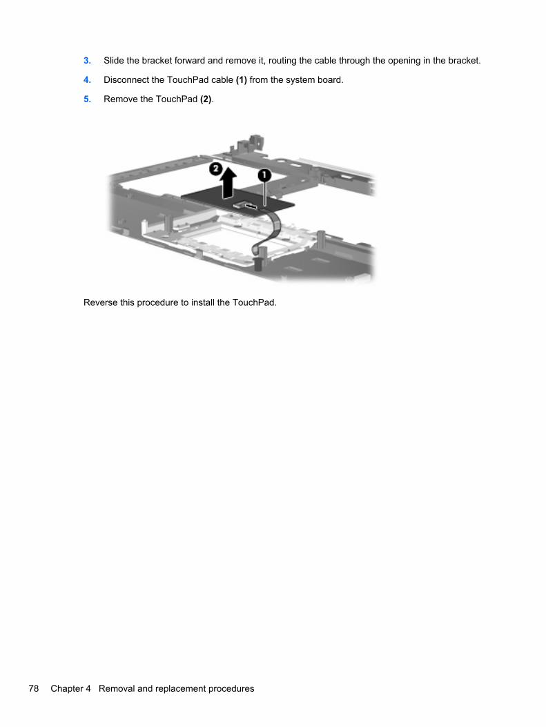
3. Slide the bracket forward and remove it, routing the cable through the opening in the bracket.
4. Disconnect the TouchPad cable (1) from the system board.
5. Remove the TouchPad (2).
Reverse this procedure to install the TouchPad.
78 Chapter 4 Removal and replacement procedures
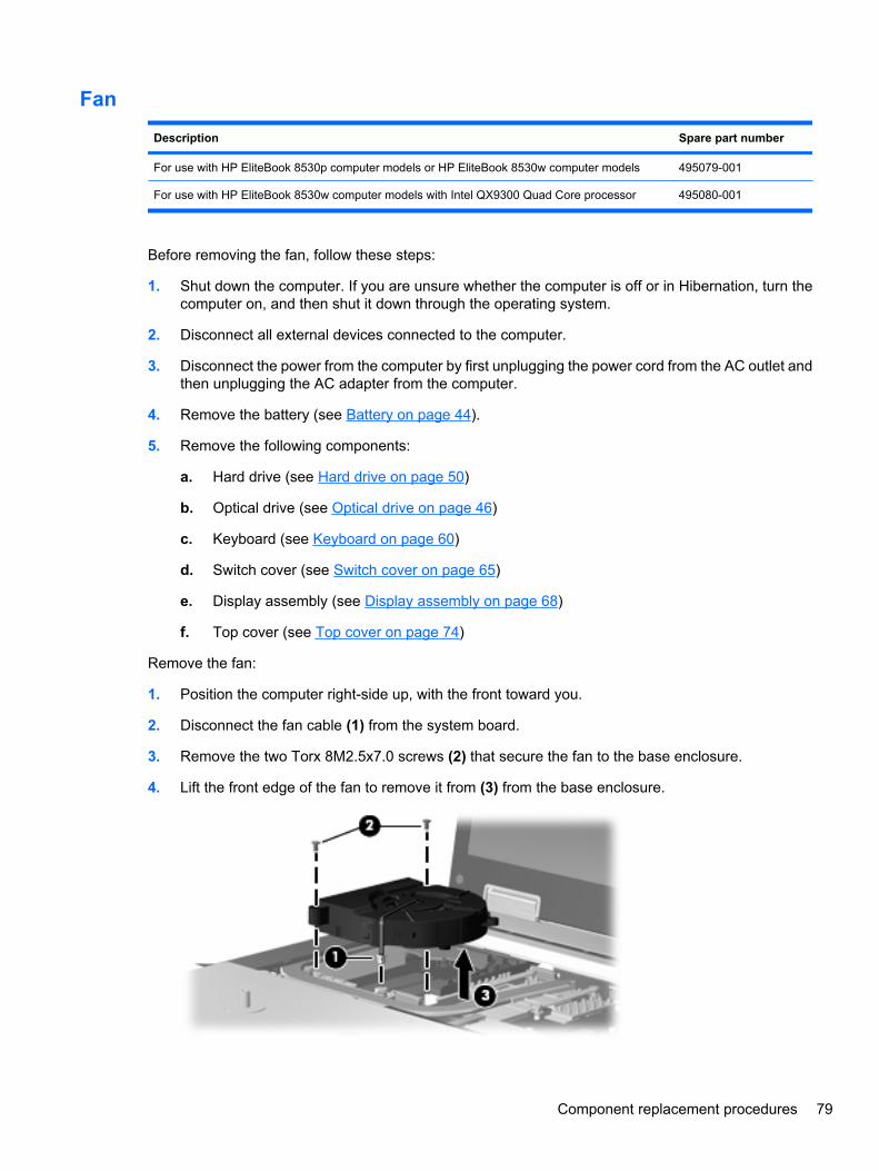
Fan
Description Spare part number
For use with HP EliteBook 8530p computer models or HP EliteBook 8530w computer models 495079-001
For use with HP EliteBook 8530w computer models with Intel QX9300 Quad Core processor 495080-001
Before removing the fan, follow these steps:
1. Shut down the computer. If you are unsure whether the computer is off or in Hibernation, turn thecomputer on, and then shut it down through the operating system.
2. Disconnect all external devices connected to the computer.
3. Disconnect the power from the computer by first unplugging the power cord from the AC outlet andthen unplugging the AC adapter from the computer.
4. Remove the battery (see Battery on page 44).
5. Remove the following components:
a. Hard drive (see Hard drive on page 50)
b. Optical drive (see Optical drive on page 46)
c. Keyboard (see Keyboard on page 60)
d. Switch cover (see Switch cover on page 65)
e. Display assembly (see Display assembly on page 68)
f. Top cover (see Top cover on page 74)
Remove the fan:
1. Position the computer right-side up, with the front toward you.
2. Disconnect the fan cable (1) from the system board.
3. Remove the two Torx 8M2.5x7.0 screws (2) that secure the fan to the base enclosure.
4. Lift the front edge of the fan to remove it from (3) from the base enclosure.
Component replacement procedures 79

Reverse this procedure to install the fan.
NOTE: To properly ventilate the computer, allow at least a 7.6-cm (3-in) clearance on the left side ofthe computer.
The computer uses an electric fan for ventilation. The fan is controlled by a temperature sensor and isdesigned to turn on automatically when high temperature conditions exist. These conditions are affectedby high external temperatures, system power consumption, power management/battery conservationconfigurations, battery fast charging, and software requirements. Exhaust air is displaced through theventilation grill located on the left side of the computer.
80 Chapter 4 Removal and replacement procedures
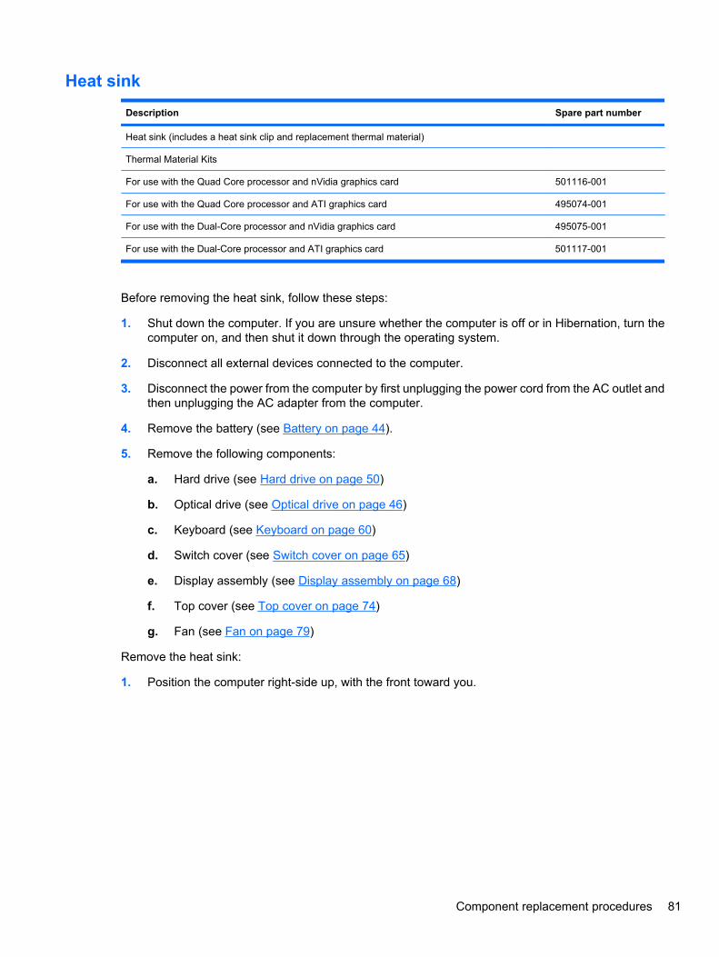
Heat sink
Description Spare part number
Heat sink (includes a heat sink clip and replacement thermal material)
Thermal Material Kits
For use with the Quad Core processor and nVidia graphics card 501116-001
For use with the Quad Core processor and ATI graphics card 495074-001
For use with the Dual-Core processor and nVidia graphics card 495075-001
For use with the Dual-Core processor and ATI graphics card 501117-001
Before removing the heat sink, follow these steps:
1. Shut down the computer. If you are unsure whether the computer is off or in Hibernation, turn thecomputer on, and then shut it down through the operating system.
2. Disconnect all external devices connected to the computer.
3. Disconnect the power from the computer by first unplugging the power cord from the AC outlet andthen unplugging the AC adapter from the computer.
4. Remove the battery (see Battery on page 44).
5. Remove the following components:
a. Hard drive (see Hard drive on page 50)
b. Optical drive (see Optical drive on page 46)
c. Keyboard (see Keyboard on page 60)
d. Switch cover (see Switch cover on page 65)
e. Display assembly (see Display assembly on page 68)
f. Top cover (see Top cover on page 74)
g. Fan (see Fan on page 79)
Remove the heat sink:
1. Position the computer right-side up, with the front toward you.
Component replacement procedures 81
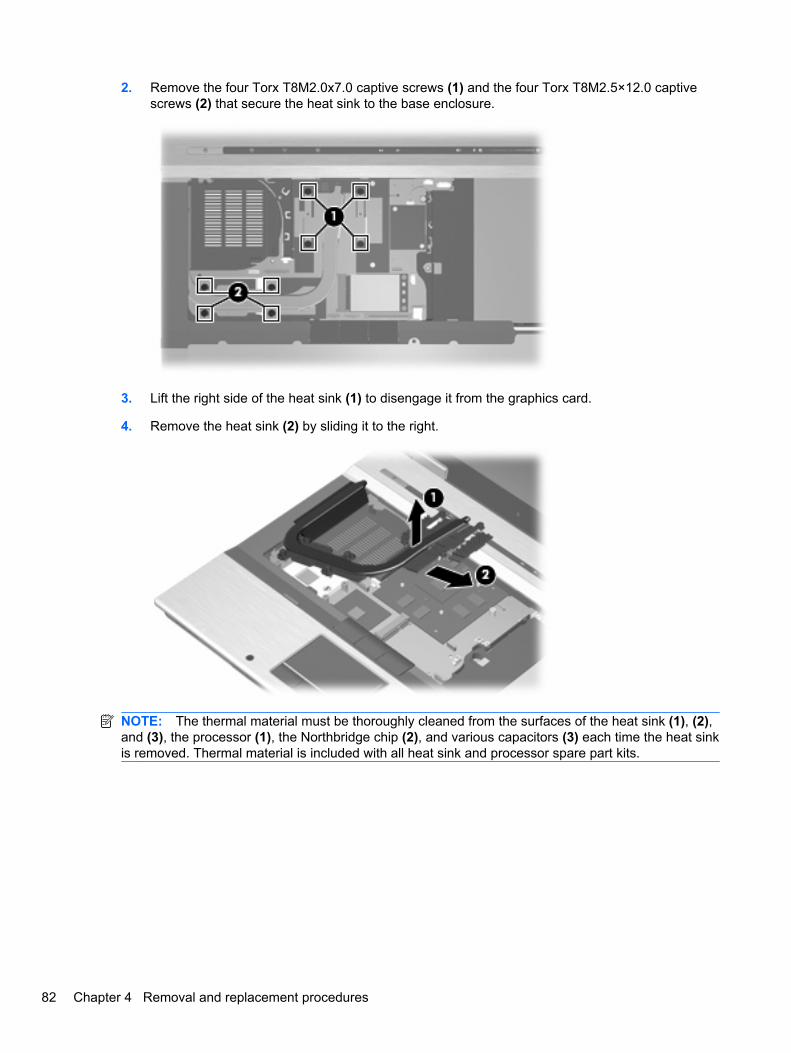
2. Remove the four Torx T8M2.0x7.0 captive screws (1) and the four Torx T8M2.5×12.0 captivescrews (2) that secure the heat sink to the base enclosure.
3. Lift the right side of the heat sink (1) to disengage it from the graphics card.
4. Remove the heat sink (2) by sliding it to the right.
NOTE: The thermal material must be thoroughly cleaned from the surfaces of the heat sink (1), (2),and (3), the processor (1), the Northbridge chip (2), and various capacitors (3) each time the heat sinkis removed. Thermal material is included with all heat sink and processor spare part kits.
82 Chapter 4 Removal and replacement procedures
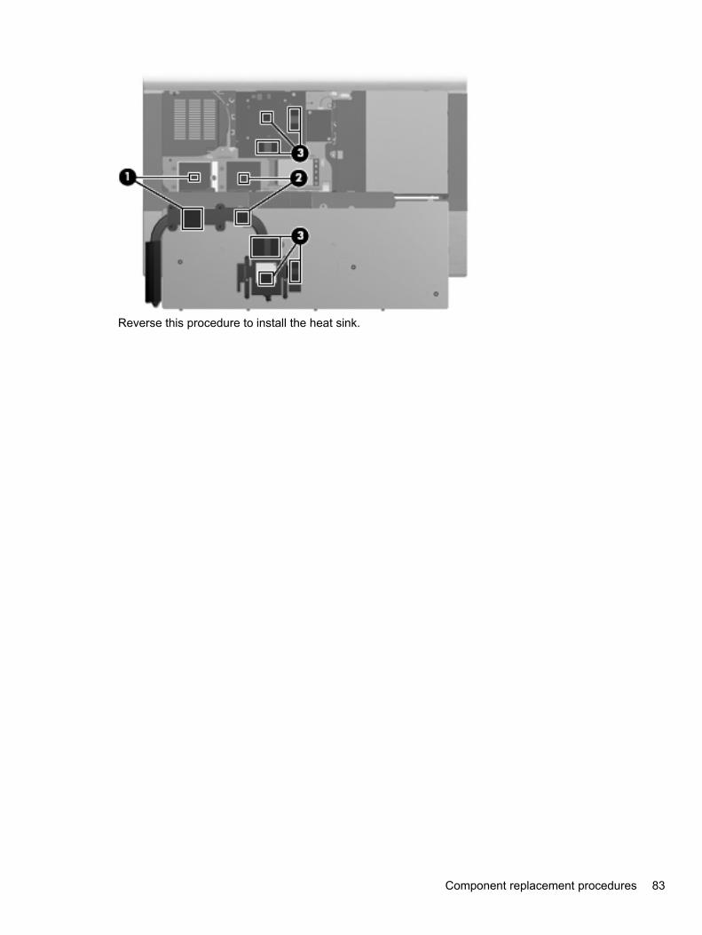
Reverse this procedure to install the heat sink.
Component replacement procedures 83
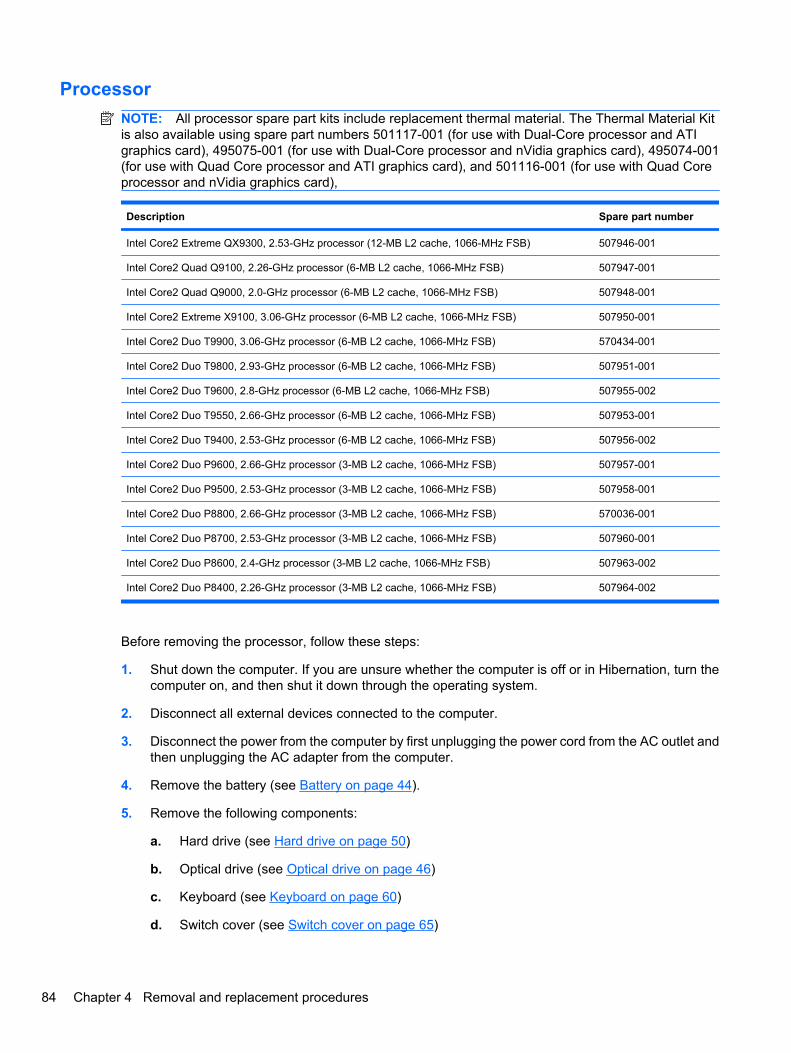
ProcessorNOTE: All processor spare part kits include replacement thermal material. The Thermal Material Kitis also available using spare part numbers 501117-001 (for use with Dual-Core processor and ATIgraphics card), 495075-001 (for use with Dual-Core processor and nVidia graphics card), 495074-001(for use with Quad Core processor and ATI graphics card), and 501116-001 (for use with Quad Coreprocessor and nVidia graphics card),
Description Spare part number
Intel Core2 Extreme QX9300, 2.53-GHz processor (12-MB L2 cache, 1066-MHz FSB) 507946-001
Intel Core2 Quad Q9100, 2.26-GHz processor (6-MB L2 cache, 1066-MHz FSB) 507947-001
Intel Core2 Quad Q9000, 2.0-GHz processor (6-MB L2 cache, 1066-MHz FSB) 507948-001
Intel Core2 Extreme X9100, 3.06-GHz processor (6-MB L2 cache, 1066-MHz FSB) 507950-001
Intel Core2 Duo T9900, 3.06-GHz processor (6-MB L2 cache, 1066-MHz FSB) 570434-001
Intel Core2 Duo T9800, 2.93-GHz processor (6-MB L2 cache, 1066-MHz FSB) 507951-001
Intel Core2 Duo T9600, 2.8-GHz processor (6-MB L2 cache, 1066-MHz FSB) 507955-002
Intel Core2 Duo T9550, 2.66-GHz processor (6-MB L2 cache, 1066-MHz FSB) 507953-001
Intel Core2 Duo T9400, 2.53-GHz processor (6-MB L2 cache, 1066-MHz FSB) 507956-002
Intel Core2 Duo P9600, 2.66-GHz processor (3-MB L2 cache, 1066-MHz FSB) 507957-001
Intel Core2 Duo P9500, 2.53-GHz processor (3-MB L2 cache, 1066-MHz FSB) 507958-001
Intel Core2 Duo P8800, 2.66-GHz processor (3-MB L2 cache, 1066-MHz FSB) 570036-001
Intel Core2 Duo P8700, 2.53-GHz processor (3-MB L2 cache, 1066-MHz FSB) 507960-001
Intel Core2 Duo P8600, 2.4-GHz processor (3-MB L2 cache, 1066-MHz FSB) 507963-002
Intel Core2 Duo P8400, 2.26-GHz processor (3-MB L2 cache, 1066-MHz FSB) 507964-002
Before removing the processor, follow these steps:
1. Shut down the computer. If you are unsure whether the computer is off or in Hibernation, turn thecomputer on, and then shut it down through the operating system.
2. Disconnect all external devices connected to the computer.
3. Disconnect the power from the computer by first unplugging the power cord from the AC outlet andthen unplugging the AC adapter from the computer.
4. Remove the battery (see Battery on page 44).
5. Remove the following components:
a. Hard drive (see Hard drive on page 50)
b. Optical drive (see Optical drive on page 46)
c. Keyboard (see Keyboard on page 60)
d. Switch cover (see Switch cover on page 65)
84 Chapter 4 Removal and replacement procedures
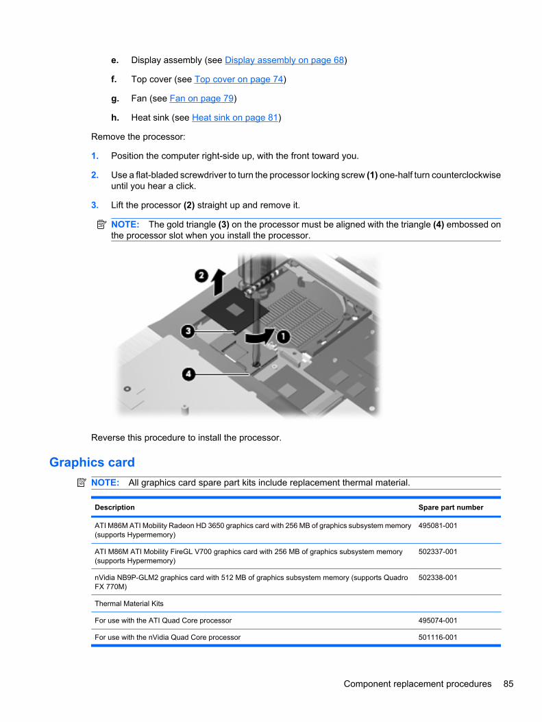
e. Display assembly (see Display assembly on page 68)
f. Top cover (see Top cover on page 74)
g. Fan (see Fan on page 79)
h. Heat sink (see Heat sink on page 81)
Remove the processor:
1. Position the computer right-side up, with the front toward you.
2. Use a flat-bladed screwdriver to turn the processor locking screw (1) one-half turn counterclockwiseuntil you hear a click.
3. Lift the processor (2) straight up and remove it.
NOTE: The gold triangle (3) on the processor must be aligned with the triangle (4) embossed onthe processor slot when you install the processor.
Reverse this procedure to install the processor.
Graphics cardNOTE: All graphics card spare part kits include replacement thermal material.
Description Spare part number
ATI M86M ATI Mobility Radeon HD 3650 graphics card with 256 MB of graphics subsystem memory(supports Hypermemory)
495081-001
ATI M86M ATI Mobility FireGL V700 graphics card with 256 MB of graphics subsystem memory(supports Hypermemory)
502337-001
nVidia NB9P-GLM2 graphics card with 512 MB of graphics subsystem memory (supports QuadroFX 770M)
502338-001
Thermal Material Kits
For use with the ATI Quad Core processor 495074-001
For use with the nVidia Quad Core processor 501116-001
Component replacement procedures 85
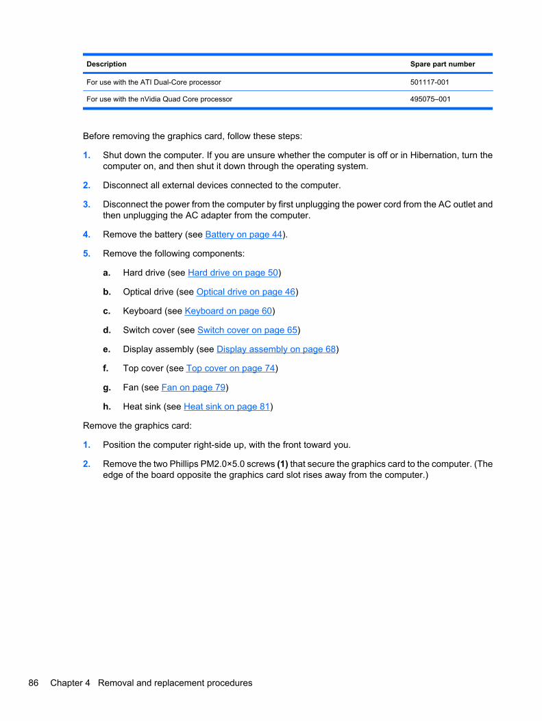
Description Spare part number
For use with the ATI Dual-Core processor 501117-001
For use with the nVidia Quad Core processor 495075–001
Before removing the graphics card, follow these steps:
1. Shut down the computer. If you are unsure whether the computer is off or in Hibernation, turn thecomputer on, and then shut it down through the operating system.
2. Disconnect all external devices connected to the computer.
3. Disconnect the power from the computer by first unplugging the power cord from the AC outlet andthen unplugging the AC adapter from the computer.
4. Remove the battery (see Battery on page 44).
5. Remove the following components:
a. Hard drive (see Hard drive on page 50)
b. Optical drive (see Optical drive on page 46)
c. Keyboard (see Keyboard on page 60)
d. Switch cover (see Switch cover on page 65)
e. Display assembly (see Display assembly on page 68)
f. Top cover (see Top cover on page 74)
g. Fan (see Fan on page 79)
h. Heat sink (see Heat sink on page 81)
Remove the graphics card:
1. Position the computer right-side up, with the front toward you.
2. Remove the two Phillips PM2.0×5.0 screws (1) that secure the graphics card to the computer. (Theedge of the board opposite the graphics card slot rises away from the computer.)
86 Chapter 4 Removal and replacement procedures
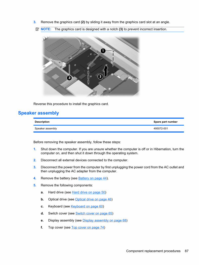
3. Remove the graphics card (2) by sliding it away from the graphics card slot at an angle.
NOTE: The graphics card is designed with a notch (3) to prevent incorrect insertion.
Reverse this procedure to install the graphics card.
Speaker assembly
Description Spare part number
Speaker assembly 495072-001
Before removing the speaker assembly, follow these steps:
1. Shut down the computer. If you are unsure whether the computer is off or in Hibernation, turn thecomputer on, and then shut it down through the operating system.
2. Disconnect all external devices connected to the computer.
3. Disconnect the power from the computer by first unplugging the power cord from the AC outlet andthen unplugging the AC adapter from the computer.
4. Remove the battery (see Battery on page 44).
5. Remove the following components:
a. Hard drive (see Hard drive on page 50)
b. Optical drive (see Optical drive on page 46)
c. Keyboard (see Keyboard on page 60)
d. Switch cover (see Switch cover on page 65)
e. Display assembly (see Display assembly on page 68)
f. Top cover (see Top cover on page 74)
Component replacement procedures 87
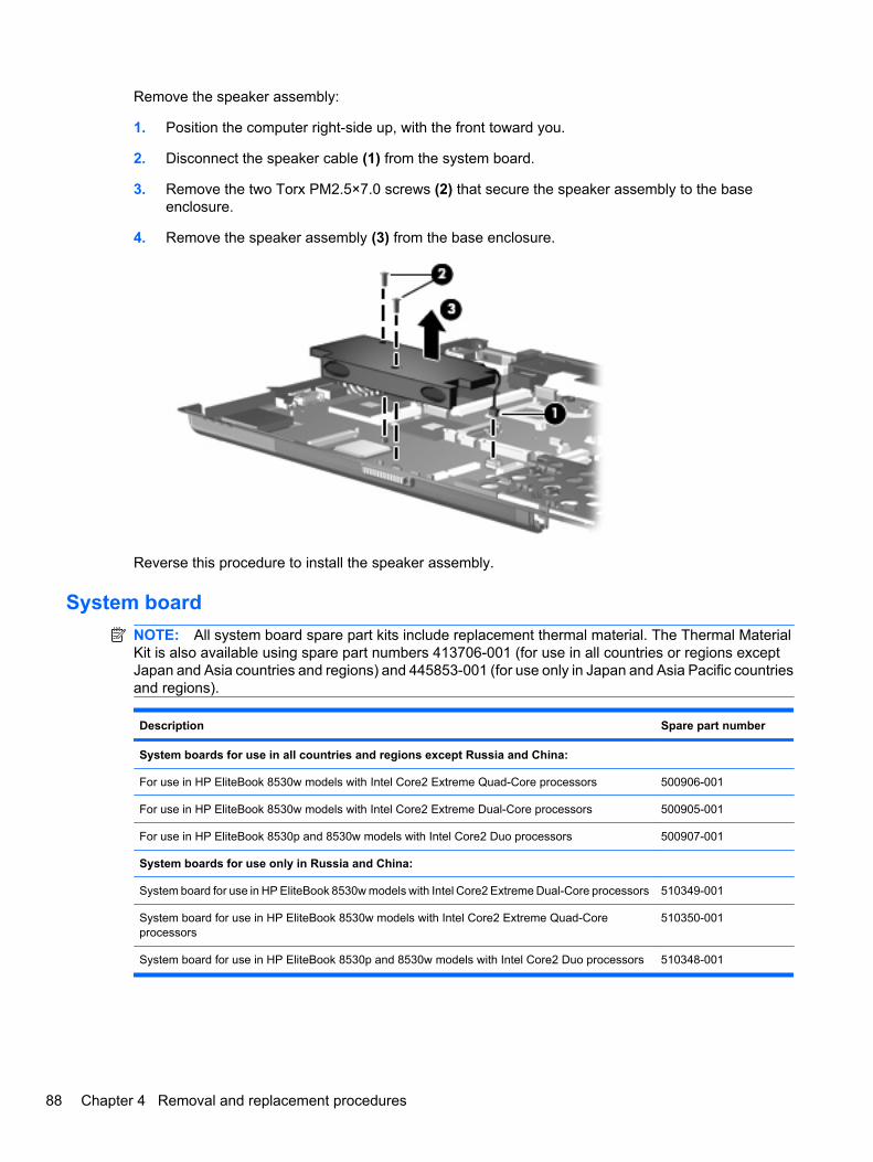
Remove the speaker assembly:
1. Position the computer right-side up, with the front toward you.
2. Disconnect the speaker cable (1) from the system board.
3. Remove the two Torx PM2.5×7.0 screws (2) that secure the speaker assembly to the baseenclosure.
4. Remove the speaker assembly (3) from the base enclosure.
Reverse this procedure to install the speaker assembly.
System boardNOTE: All system board spare part kits include replacement thermal material. The Thermal MaterialKit is also available using spare part numbers 413706-001 (for use in all countries or regions exceptJapan and Asia countries and regions) and 445853-001 (for use only in Japan and Asia Pacific countriesand regions).
Description Spare part number
System boards for use in all countries and regions except Russia and China:
For use in HP EliteBook 8530w models with Intel Core2 Extreme Quad-Core processors 500906-001
For use in HP EliteBook 8530w models with Intel Core2 Extreme Dual-Core processors 500905-001
For use in HP EliteBook 8530p and 8530w models with Intel Core2 Duo processors 500907-001
System boards for use only in Russia and China:
System board for use in HP EliteBook 8530w models with Intel Core2 Extreme Dual-Core processors 510349-001
System board for use in HP EliteBook 8530w models with Intel Core2 Extreme Quad-Coreprocessors
510350-001
System board for use in HP EliteBook 8530p and 8530w models with Intel Core2 Duo processors 510348-001
88 Chapter 4 Removal and replacement procedures
Before removing the system board, follow these steps:
1. Shut down the computer. If you are unsure whether the computer is off or in Hibernation, turn thecomputer on, and then shut it down through the operating system.
2. Disconnect all external devices connected to the computer.
3. Disconnect the power from the computer by first unplugging the power cord from the AC outlet andthen unplugging the AC adapter from the computer.
4. Remove the battery (see Battery on page 44).
5. Remove the following components:
a. Hard drive (see Hard drive on page 50)
b. Optical drive (see Optical drive on page 46)
c. Keyboard (see Keyboard on page 60)
d. Switch cover (see Switch cover on page 65)
e. Display assembly (see Display assembly on page 68)
f. Top cover (see Top cover on page 74)
g. Fan (see Fan on page 79)
h. Heat sink (see Heat sink on page 81)
i. Speaker assembly (see Speaker assembly on page 87)
j. Modem module (see Modem module on page 63)
When replacing the system board, be sure that the following components are removed from the defectivesystem board and installed on the replacement system board:
● SIM (see SIM on page 45)
● Memory module (see Memory modules on page 56)
● WLAN module (see WLAN module on page 64)
● WWAN module (see WWAN module on page 58)
● Processor (see Processor on page 84)
● Graphics card (see Graphics card on page 85)
● ExpressCard assembly (see ExpressCard assembly on page 92)
Remove the system board:
1. Position the computer right-side up, with the front toward you.
Component replacement procedures 89
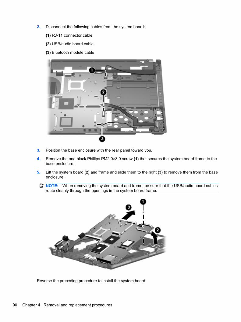
2. Disconnect the following cables from the system board:
(1) RJ-11 connector cable
(2) USB/audio board cable
(3) Bluetooth module cable
3. Position the base enclosure with the rear panel toward you.
4. Remove the one black Phillips PM2.0×3.0 screw (1) that secures the system board frame to thebase enclosure.
5. Lift the system board (2) and frame and slide them to the right (3) to remove them from the baseenclosure.
NOTE: When removing the system board and frame, be sure that the USB/audio board cablesroute cleanly through the openings in the system board frame.
Reverse the preceding procedure to install the system board.
90 Chapter 4 Removal and replacement procedures
RJ-11 connector cableNOTE: The RJ-11 connector cable is included in the Cables Kit, spare part number 452198-001.
Before removing the RJ-11 connector cable, follow these steps:
1. Shut down the computer. If you are unsure whether the computer is off or in Hibernation, turn thecomputer on, and then shut it down through the operating system.
2. Disconnect all external devices connected to the computer.
3. Disconnect the power from the computer by first unplugging the power cord from the AC outlet andthen unplugging the AC adapter from the computer.
4. Remove the battery (see Battery on page 44).
5. Remove the following components:
a. Hard drive (see Hard drive on page 50)
b. Optical drive (see Optical drive on page 46)
c. Keyboard (see Keyboard on page 60)
d. Switch cover (see Switch cover on page 65)
e. Display assembly (see Display assembly on page 68)
f. Top cover (see Top cover on page 74)
g. Fan (see Fan on page 79)
h. Heat sink (see Heat sink on page 81)
i. Modem module (see Modem module on page 63)
j. System board (see System board on page 88)
Remove the RJ-11 connector cable:
1. Position the computer right-side up, with the front toward you.
2. Remove the RJ-11 connector (1) from the clip built into the base enclosure.
Component replacement procedures 91
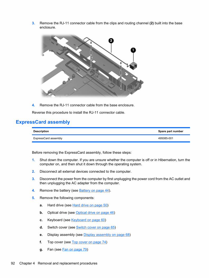
3. Remove the RJ-11 connector cable from the clips and routing channel (2) built into the baseenclosure.
4. Remove the RJ-11 connector cable from the base enclosure.
Reverse this procedure to install the RJ-11 connector cable.
ExpressCard assembly
Description Spare part number
ExpressCard assembly 495085-001
Before removing the ExpressCard assembly, follow these steps:
1. Shut down the computer. If you are unsure whether the computer is off or in Hibernation, turn thecomputer on, and then shut it down through the operating system.
2. Disconnect all external devices connected to the computer.
3. Disconnect the power from the computer by first unplugging the power cord from the AC outlet andthen unplugging the AC adapter from the computer.
4. Remove the battery (see Battery on page 44).
5. Remove the following components:
a. Hard drive (see Hard drive on page 50)
b. Optical drive (see Optical drive on page 46)
c. Keyboard (see Keyboard on page 60)
d. Switch cover (see Switch cover on page 65)
e. Display assembly (see Display assembly on page 68)
f. Top cover (see Top cover on page 74)
g. Fan (see Fan on page 79)
92 Chapter 4 Removal and replacement procedures
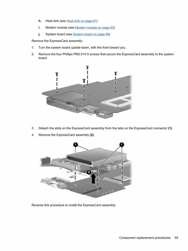
h. Heat sink (see Heat sink on page 81)
i. Modem module (see Modem module on page 63)
j. System board (see System board on page 88)
Remove the ExpressCard assembly:
1. Turn the system board upside-down, with the front toward you.
2. Remove the four Phillips PM2.0×5.0 screws that secure the ExpressCard assembly to the systemboard.
3. Detach the slots on the ExpressCard assembly from the tabs on the ExpressCard connector (1).
4. Remove the ExpressCard assembly (2).
Reverse this procedure to install the ExpressCard assembly.
Component replacement procedures 93
USB/audio board
Description Spare part number
USB/audio board (includes USB cable and audio cable) 495065-001
Before removing the USB/audio board, follow these steps:
1. Shut down the computer. If you are unsure whether the computer is off or in Hibernation, turn thecomputer on, and then shut it down through the operating system.
2. Disconnect all external devices connected to the computer.
3. Disconnect the power from the computer by first unplugging the power cord from the AC outlet andthen unplugging the AC adapter from the computer.
4. Remove the battery (see Battery on page 44).
5. Remove the following components:
a. Hard drive (see Hard drive on page 50)
b. Optical drive (see Optical drive on page 46)
c. Keyboard (see Keyboard on page 60)
d. Switch cover (see Switch cover on page 65)
e. Display assembly (see Display assembly on page 68)
f. Top cover (see Top cover on page 74)
g. Fan (see Fan on page 79)
h. Heat sink (see Heat sink on page 81)
i. Modem module (see Modem module on page 63)
j. System board (see System board on page 88)
Remove the USB/audio board:
1. Position the computer right-side up, with the front toward you.
2. Disconnect the cable from the USB/audio board (1).
3. Remove the Torx T82.5×8.0 screw (2) that secures the USB/audio board to the base enclosure.
94 Chapter 4 Removal and replacement procedures
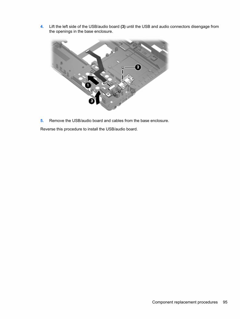
4. Lift the left side of the USB/audio board (3) until the USB and audio connectors disengage fromthe openings in the base enclosure.
5. Remove the USB/audio board and cables from the base enclosure.
Reverse this procedure to install the USB/audio board.
Component replacement procedures 95
5 Computer Setup
Starting Computer SetupComputer Setup is a preinstalled, ROM-based utility that can be used even when the operating systemis not working or will not load.
NOTE: Some of the Computer Setup menu items listed in this guide may not be supported by yourcomputer.
NOTE: An external keyboard or mouse connected to a USB port can be used with Computer Setuponly if USB legacy support is enabled.
To start Computer Setup, follow these steps:
1. Turn on or restart the computer, and then press esc while the “Press the ESC key for Startup Menu”message is displayed at the bottom of the screen.
2. Press f10 to enter BIOS Setup.
96 Chapter 5 Computer Setup
Using Computer SetupNavigating and selecting in Computer Setup
The information and settings in Computer Setup are accessed from the File, Security, Diagnostics, andSystem Configuration menus.
To navigate and select in Computer Setup, follow these steps:
1. Turn on or restart the computer, and then press esc while the “Press the ESC key for Startup Menu”message is displayed at the bottom of the screen.
● To select a menu or a menu item, use the keyboard arrow keys and then press enter, or usea pointing device to click the item.
● To scroll up and down, click the up arrow or the down arrow in the upper-right corner of thescreen.
● To close open dialog boxes and return to the main Computer Setup screen, press esc, andthen follow the on-screen instructions.
NOTE: You can use either a pointing device (TouchPad, pointing stick, or USB mouse) or thekeyboard to navigate and make selections in Computer Setup.
2. Press f10 to enter BIOS Setup.
3. Select the File, Security, Diagnostics, or System Configuration menu.
To exit Computer Setup menus, choose one of the following methods:
● To exit Computer Setup menus without saving your changes, click the Exit icon in the lower-leftcorner of the screen, and then follow the on-screen instructions.
– or –
Use the arrow keys to select File > Ignore changes and exit, and then press enter.
– or –
● To save your changes and exit Computer Setup menus, click the Save icon in the lower-left cornerof the screen, and then follow the on-screen instructions.
– or –
Use the arrow keys to select File > Save changes and exit, and then press enter.
Your changes go into effect when the computer restarts.
Restoring factory settings in Computer SetupNOTE: Restoring defaults will not change the hard drive mode.
To return all settings in Computer Setup to the values that were set at the factory, follow these steps:
1. Turn on or restart the computer, and then press esc while the “Press the ESC key for Startup Menu”message is displayed at the bottom of the screen.
2. Press f10 to enter BIOS Setup.
Using Computer Setup 97
3. Use a pointing device or the arrow keys to select File > Restore defaults.
4. Follow the on-screen instructions.
5. To save your changes and exit, click the Save icon in the lower-left corner of the screen, and thenfollow the on-screen instructions.
– or –
Use the arrow keys to select File > Save changes and exit, and then press enter.
Your changes go into effect when the computer restarts.
NOTE: Your password settings and security settings are not changed when you restore the factorysettings.
Computer Setup menusThe menu tables in this section provide an overview of Computer Setup options.
NOTE: Some of the Computer Setup menu items listed in this chapter may not be supported by yourcomputer.
File menu
Select To do this
System Information ● View identification information for the computer and thebatteries in the system.
● View specification information for the processor, cacheand memory size, system ROM, video revision, andkeyboard controller version.
Set System Date and Time Set or change the date and time on the computer.
Restore defaults Replace the configuration settings in Computer Setup with theoriginal factory settings. (Hard drive mode, password settings,and security settings are not changed when you restore thefactory settings.)
Ignore changes and exit Cancel any changes entered during the current session. Thenexit and restart the computer.
Save changes and exit Save any changes entered during the current session. Thenexit and restart the computer. Your changes go into effectwhen the computer restarts.
Security menuNOTE: Some of the menu items listed in this section may not be supported by your computer.
Select To do this
Setup BIOS Administrator Password Set up a BIOS administrator password.
98 Chapter 5 Computer Setup
Select To do this
User Management (requires a BIOS administrator password) ● Create a new BIOS user account.
● View a list of ProtectTools users.
Password Policy (requires a BIOS administrator password) Revise password policy criteria.
HP SpareKey Enable/disable HP SpareKey (enabled by default).
Always Prompt for HP SpareKey Enrollment Enable/disable HP SpareKey enrollment (enabled by default).
Fingerprint Reset on Reboot (If Present) Reset/clear the fingerprint reader ownership (select modelsonly; disabled by default).
Allow Reset of HP ProtectTools security keys Enable/disable reset of HP ProtectTools security keys.
Change Password Enter, change, or delete a BIOS administrator password.
HP SpareKey Enrollment Enroll or reset HP SpareKey, which is a set of securityquestions and answers used if you forget your password.
DriveLock Passwords ● Enable/disable DriveLock on any computer hard drive(enabled by default).
● Change a DriveLock user password or master password.
NOTE: DriveLock settings are accessible only when youenter Computer Setup by turning on (not restarting) thecomputer.
TPM Embedded Security Enable/disable support for Trusted Platform Module (TPM)Embedded Security, which protects the computer fromunauthorized access to owner functions available inEmbedded Security for ProtectTools. For more information,refer to the ProtectTools software Help.
NOTE: You must have a setup password to change thissetting.
Automatic DriveLock Enable/disable Automatic DriveLock support.
Disk Sanitizer Run Disk Sanitizer to destroy all existing data on the primaryhard drive or the drive in the upgrade bay.
CAUTION: If you run Disk Sanitizer, the data on the selecteddrive is destroyed permanently.
System IDs Enter a user-defined computer asset tracking number andownership tag.
Computer Setup menus 99
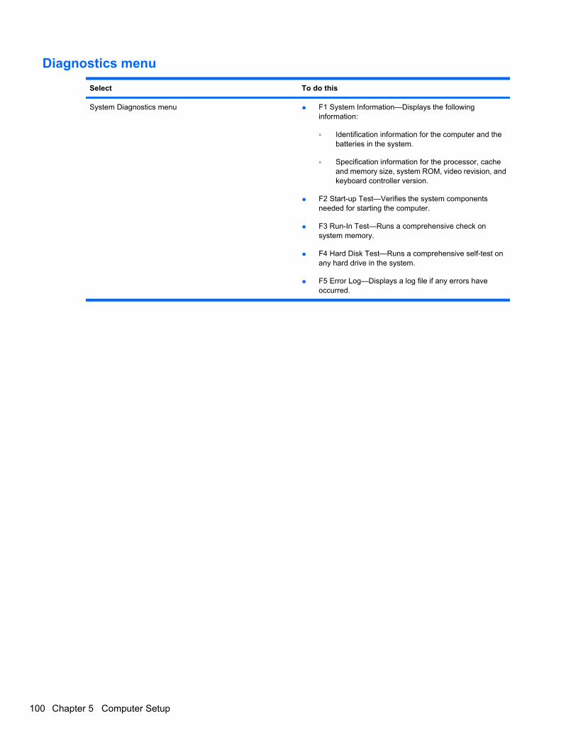
Diagnostics menu
Select To do this
System Diagnostics menu ● F1 System Information—Displays the followinginformation:
◦ Identification information for the computer and thebatteries in the system.
◦ Specification information for the processor, cacheand memory size, system ROM, video revision, andkeyboard controller version.
● F2 Start-up Test—Verifies the system componentsneeded for starting the computer.
● F3 Run-In Test—Runs a comprehensive check onsystem memory.
● F4 Hard Disk Test—Runs a comprehensive self-test onany hard drive in the system.
● F5 Error Log—Displays a log file if any errors haveoccurred.
100 Chapter 5 Computer Setup
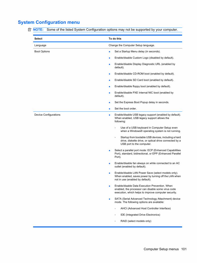
System Configuration menuNOTE: Some of the listed System Configuration options may not be supported by your computer.
Select To do this
Language Change the Computer Setup language.
Boot Options ● Set a Startup Menu delay (in seconds).
● Enable/disable Custom Logo (disabled by default).
● Enable/disable Display Diagnostic URL (enabled bydefault).
● Enable/disable CD-ROM boot (enabled by default).
● Enable/disable SD Card boot (enabled by default).
● Enable/disable floppy boot (enabled by default).
● Enable/disable PXE Internal NIC boot (enabled bydefault).
● Set the Express Boot Popup delay in seconds.
● Set the boot order.
Device Configurations ● Enable/disable USB legacy support (enabled by default).When enabled, USB legacy support allows thefollowing:
◦ Use of a USB keyboard in Computer Setup evenwhen a Windows® operating system is not running.
◦ Startup from bootable USB devices, including a harddrive, diskette drive, or optical drive connected by aUSB port to the computer.
● Select a parallel port mode: ECP (Enhanced CapabilitiesPort), standard, bidirectional, or EPP (Enhanced ParallelPort).
● Enable/disable fan always on while connected to an ACoutlet (enabled by default).
● Enable/disable LAN Power Save (select models only).When enabled, saves power by turning off the LAN whennot in use (enabled by default).
● Enable/disable Data Execution Prevention. Whenenabled, the processor can disable some virus codeexecution, which helps to improve computer security.
● SATA (Serial Advanced Technology Attachment) devicemode. The following options are available:
◦ AHCI (Advanced Host Controller Interface)
◦ IDE (Integrated Drive Electronics)
◦ RAID (select models only)
Computer Setup menus 101
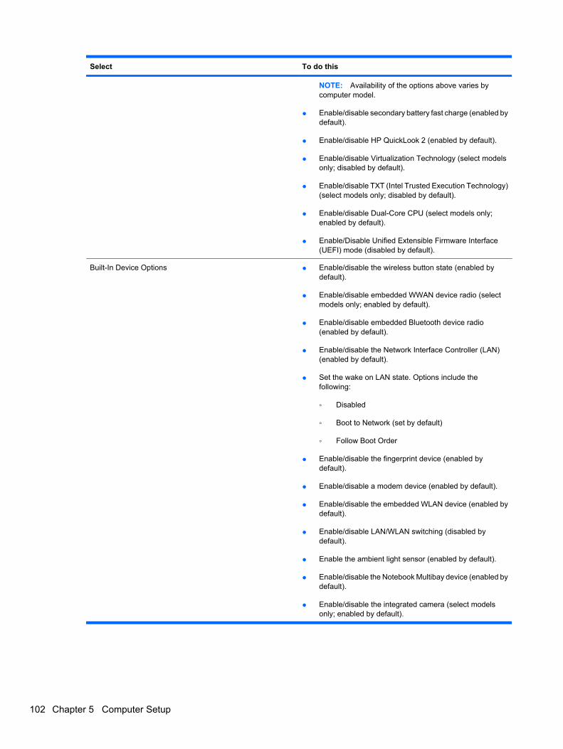
Select To do this
NOTE: Availability of the options above varies bycomputer model.
● Enable/disable secondary battery fast charge (enabled bydefault).
● Enable/disable HP QuickLook 2 (enabled by default).
● Enable/disable Virtualization Technology (select modelsonly; disabled by default).
● Enable/disable TXT (Intel Trusted Execution Technology)(select models only; disabled by default).
● Enable/disable Dual-Core CPU (select models only;enabled by default).
● Enable/Disable Unified Extensible Firmware Interface(UEFI) mode (disabled by default).
Built-In Device Options ● Enable/disable the wireless button state (enabled bydefault).
● Enable/disable embedded WWAN device radio (selectmodels only; enabled by default).
● Enable/disable embedded Bluetooth device radio(enabled by default).
● Enable/disable the Network Interface Controller (LAN)(enabled by default).
● Set the wake on LAN state. Options include thefollowing:
◦ Disabled
◦ Boot to Network (set by default)
◦ Follow Boot Order
● Enable/disable the fingerprint device (enabled bydefault).
● Enable/disable a modem device (enabled by default).
● Enable/disable the embedded WLAN device (enabled bydefault).
● Enable/disable LAN/WLAN switching (disabled bydefault).
● Enable the ambient light sensor (enabled by default).
● Enable/disable the Notebook Multibay device (enabled bydefault).
● Enable/disable the integrated camera (select modelsonly; enabled by default).
102 Chapter 5 Computer Setup
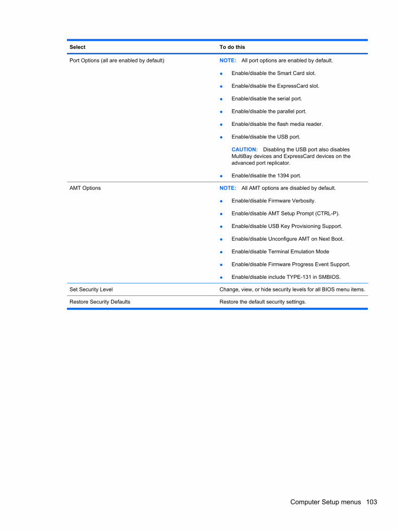
Select To do this
Port Options (all are enabled by default) NOTE: All port options are enabled by default.
● Enable/disable the Smart Card slot.
● Enable/disable the ExpressCard slot.
● Enable/disable the serial port.
● Enable/disable the parallel port.
● Enable/disable the flash media reader.
● Enable/disable the USB port.
CAUTION: Disabling the USB port also disablesMultiBay devices and ExpressCard devices on theadvanced port replicator.
● Enable/disable the 1394 port.
AMT Options NOTE: All AMT options are disabled by default.
● Enable/disable Firmware Verbosity.
● Enable/disable AMT Setup Prompt (CTRL-P).
● Enable/disable USB Key Provisioning Support.
● Enable/disable Unconfigure AMT on Next Boot.
● Enable/disable Terminal Emulation Mode
● Enable/disable Firmware Progress Event Support.
● Enable/disable include TYPE-131 in SMBIOS.
Set Security Level Change, view, or hide security levels for all BIOS menu items.
Restore Security Defaults Restore the default security settings.
Computer Setup menus 103
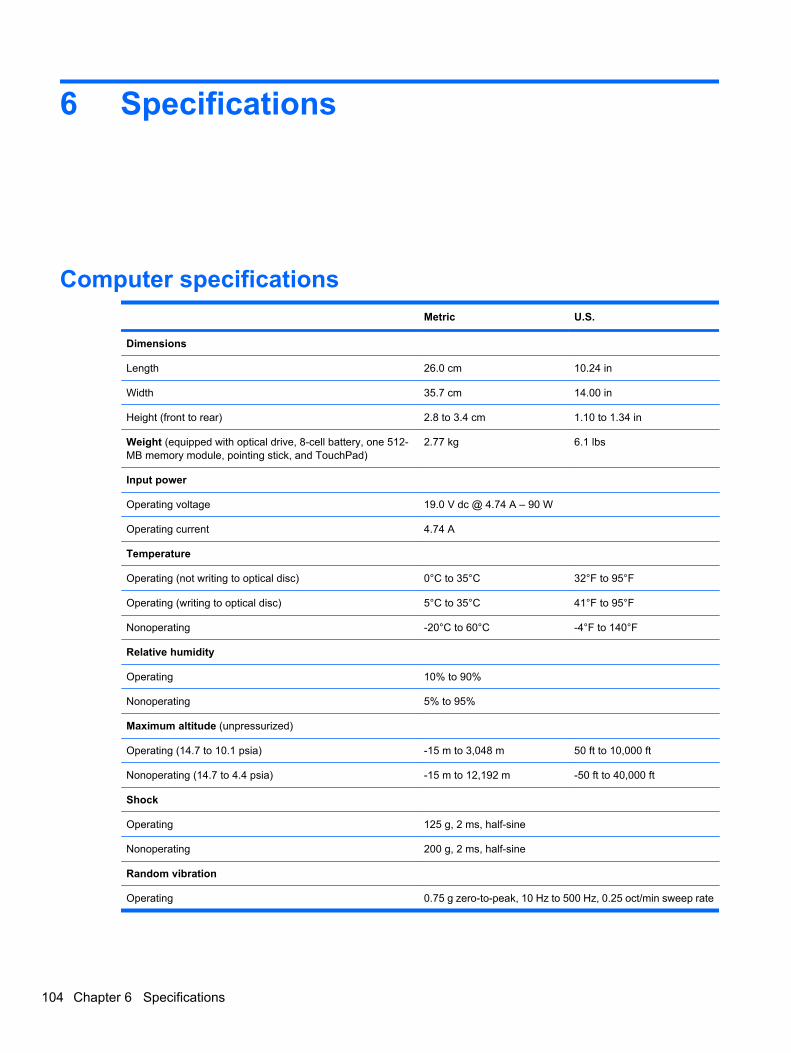
6 Specifications
Computer specifications Metric U.S.
Dimensions
Length 26.0 cm 10.24 in
Width 35.7 cm 14.00 in
Height (front to rear) 2.8 to 3.4 cm 1.10 to 1.34 in
Weight (equipped with optical drive, 8-cell battery, one 512-MB memory module, pointing stick, and TouchPad)
2.77 kg 6.1 lbs
Input power
Operating voltage 19.0 V dc @ 4.74 A – 90 W
Operating current 4.74 A
Temperature
Operating (not writing to optical disc) 0°C to 35°C 32°F to 95°F
Operating (writing to optical disc) 5°C to 35°C 41°F to 95°F
Nonoperating -20°C to 60°C -4°F to 140°F
Relative humidity
Operating 10% to 90%
Nonoperating 5% to 95%
Maximum altitude (unpressurized)
Operating (14.7 to 10.1 psia) -15 m to 3,048 m 50 ft to 10,000 ft
Nonoperating (14.7 to 4.4 psia) -15 m to 12,192 m -50 ft to 40,000 ft
Shock
Operating 125 g, 2 ms, half-sine
Nonoperating 200 g, 2 ms, half-sine
Random vibration
Operating 0.75 g zero-to-peak, 10 Hz to 500 Hz, 0.25 oct/min sweep rate
104 Chapter 6 Specifications
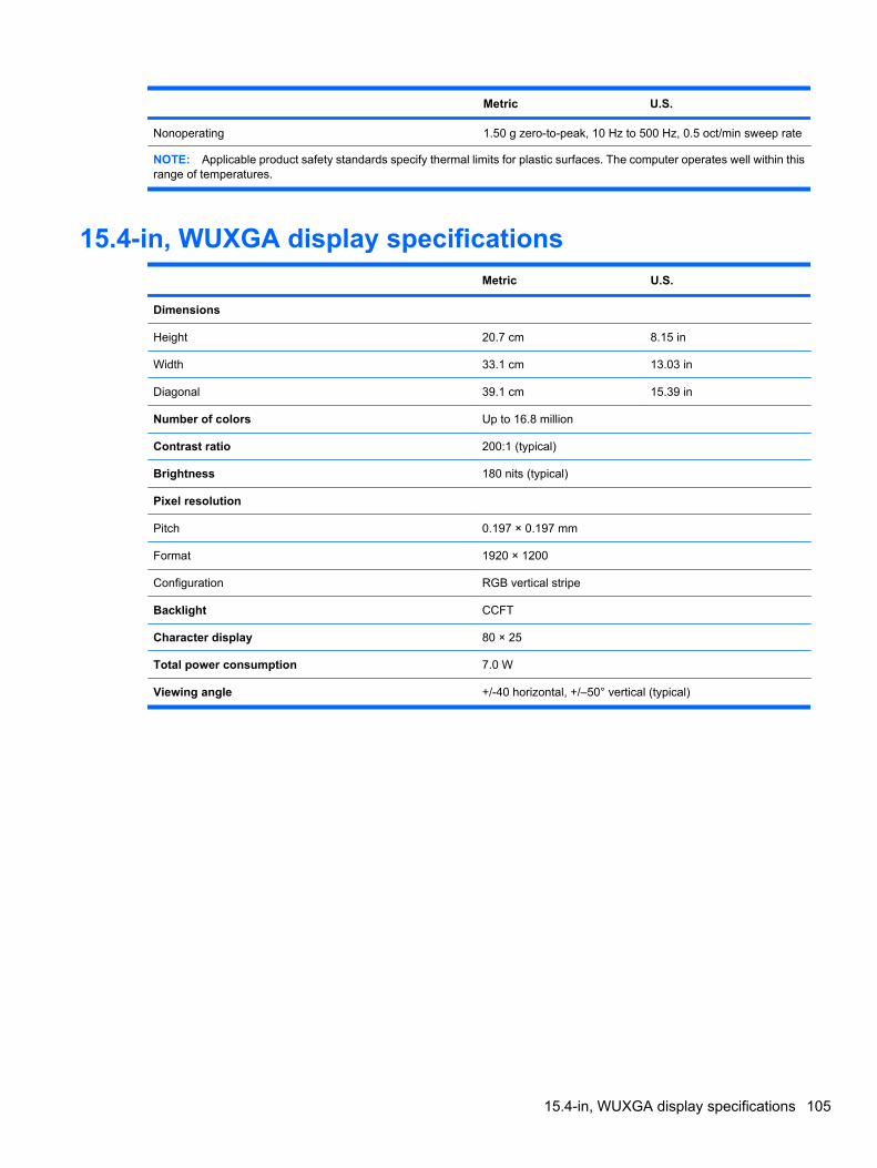
Metric U.S.
Nonoperating 1.50 g zero-to-peak, 10 Hz to 500 Hz, 0.5 oct/min sweep rate
NOTE: Applicable product safety standards specify thermal limits for plastic surfaces. The computer operates well within thisrange of temperatures.
15.4-in, WUXGA display specifications Metric U.S.
Dimensions
Height 20.7 cm 8.15 in
Width 33.1 cm 13.03 in
Diagonal 39.1 cm 15.39 in
Number of colors Up to 16.8 million
Contrast ratio 200:1 (typical)
Brightness 180 nits (typical)
Pixel resolution
Pitch 0.197 × 0.197 mm
Format 1920 × 1200
Configuration RGB vertical stripe
Backlight CCFT
Character display 80 × 25
Total power consumption 7.0 W
Viewing angle +/-40 horizontal, +/–50° vertical (typical)
15.4-in, WUXGA display specifications 105
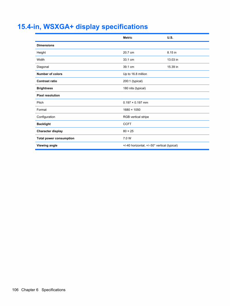
15.4-in, WSXGA+ display specifications Metric U.S.
Dimensions
Height 20.7 cm 8.15 in
Width 33.1 cm 13.03 in
Diagonal 39.1 cm 15.39 in
Number of colors Up to 16.8 million
Contrast ratio 200:1 (typical)
Brightness 180 nits (typical)
Pixel resolution
Pitch 0.197 × 0.197 mm
Format 1680 × 1050
Configuration RGB vertical stripe
Backlight CCFT
Character display 80 × 25
Total power consumption 7.0 W
Viewing angle +/-40 horizontal, +/–50° vertical (typical)
106 Chapter 6 Specifications
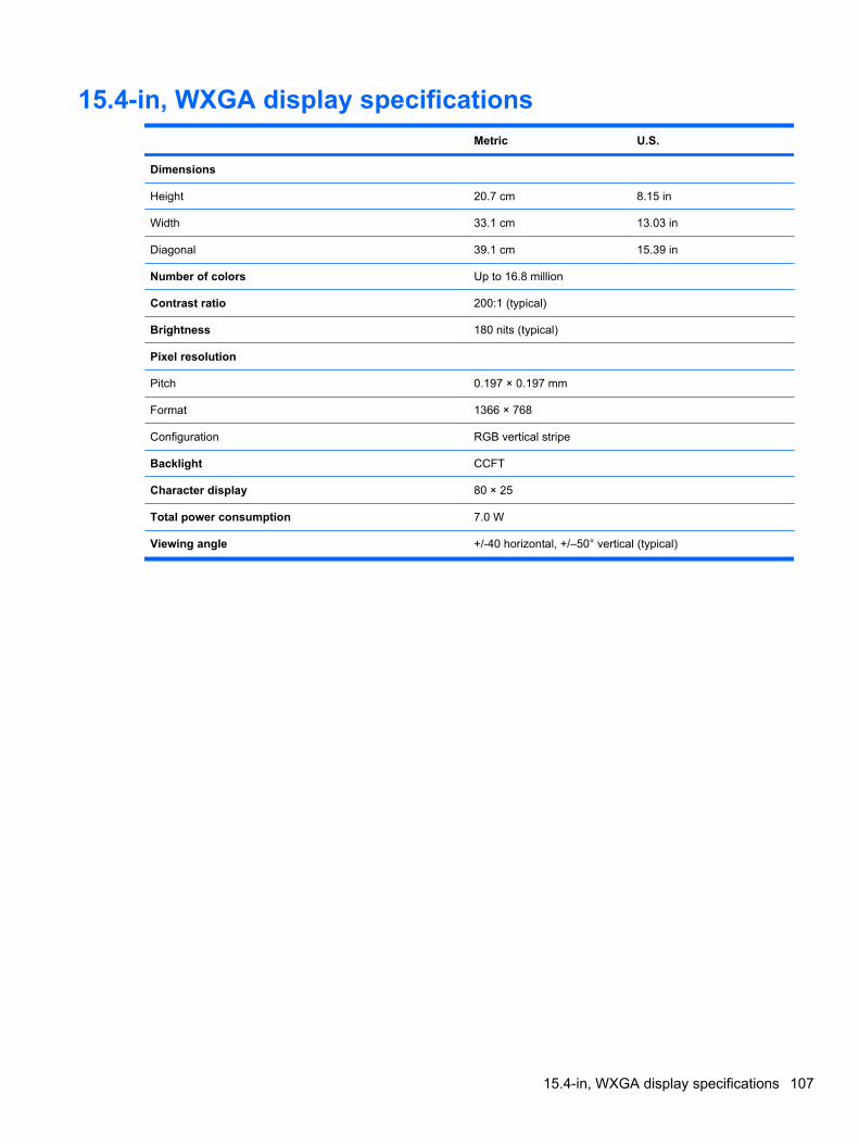
15.4-in, WXGA display specifications Metric U.S.
Dimensions
Height 20.7 cm 8.15 in
Width 33.1 cm 13.03 in
Diagonal 39.1 cm 15.39 in
Number of colors Up to 16.8 million
Contrast ratio 200:1 (typical)
Brightness 180 nits (typical)
Pixel resolution
Pitch 0.197 × 0.197 mm
Format 1366 × 768
Configuration RGB vertical stripe
Backlight CCFT
Character display 80 × 25
Total power consumption 7.0 W
Viewing angle +/-40 horizontal, +/–50° vertical (typical)
15.4-in, WXGA display specifications 107
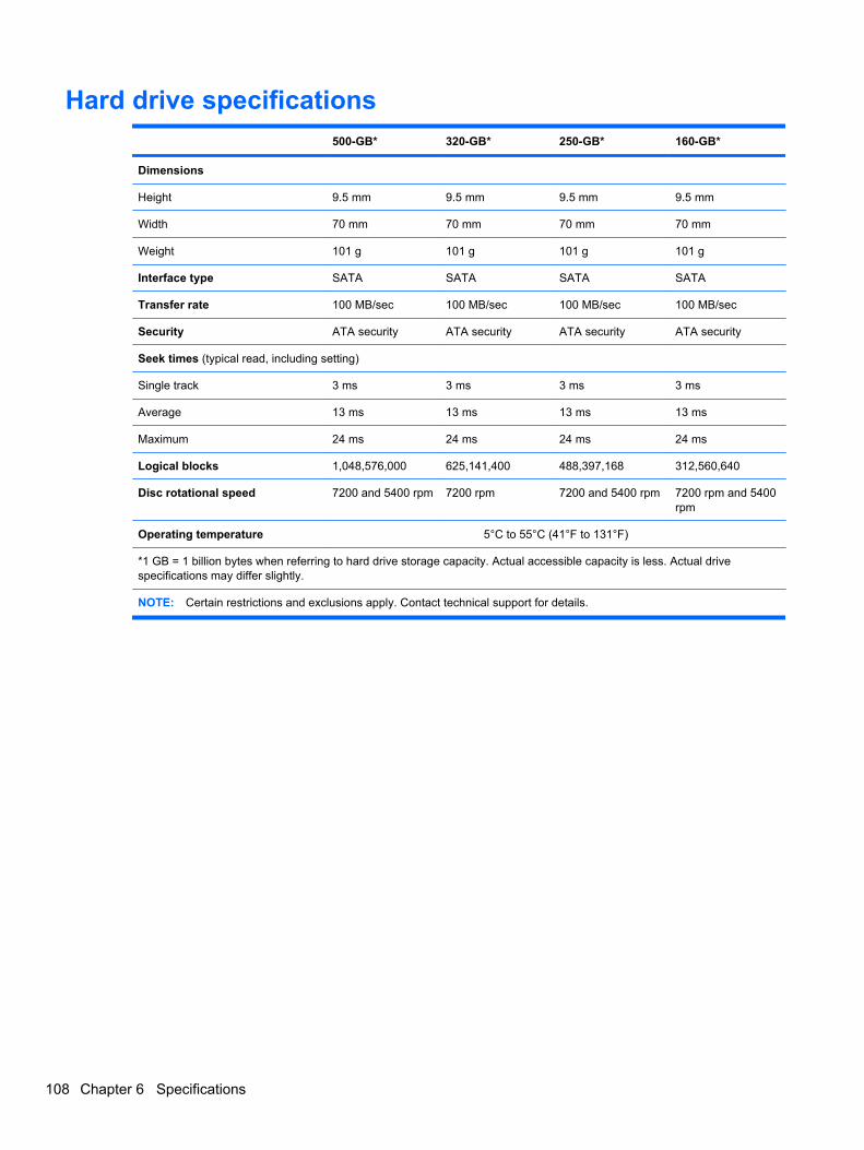
Hard drive specifications 500-GB* 320-GB* 250-GB* 160-GB*
Dimensions
Height 9.5 mm 9.5 mm 9.5 mm 9.5 mm
Width 70 mm 70 mm 70 mm 70 mm
Weight 101 g 101 g 101 g 101 g
Interface type SATA SATA SATA SATA
Transfer rate 100 MB/sec 100 MB/sec 100 MB/sec 100 MB/sec
Security ATA security ATA security ATA security ATA security
Seek times (typical read, including setting)
Single track 3 ms 3 ms 3 ms 3 ms
Average 13 ms 13 ms 13 ms 13 ms
Maximum 24 ms 24 ms 24 ms 24 ms
Logical blocks 1,048,576,000 625,141,400 488,397,168 312,560,640
Disc rotational speed 7200 and 5400 rpm 7200 rpm 7200 and 5400 rpm 7200 rpm and 5400rpm
Operating temperature 5°C to 55°C (41°F to 131°F)
*1 GB = 1 billion bytes when referring to hard drive storage capacity. Actual accessible capacity is less. Actual drivespecifications may differ slightly.
NOTE: Certain restrictions and exclusions apply. Contact technical support for details.
108 Chapter 6 Specifications
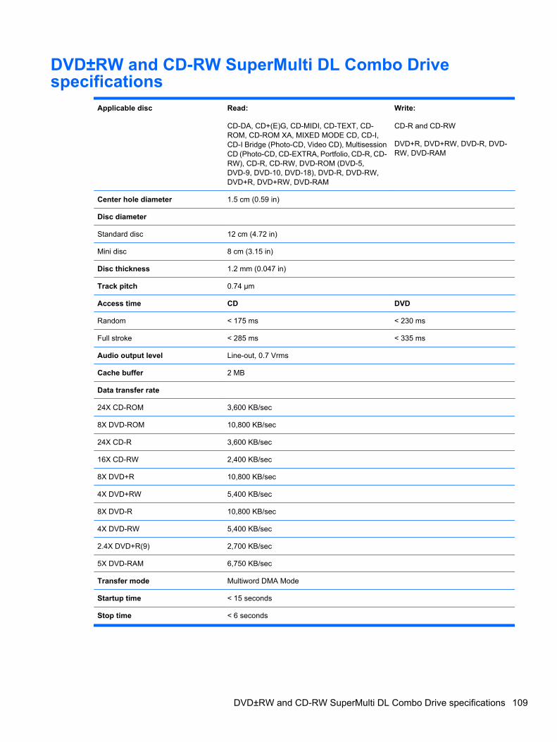
DVD±RW and CD-RW SuperMulti DL Combo Drivespecifications
Applicable disc Read:
CD-DA, CD+(E)G, CD-MIDI, CD-TEXT, CD-ROM, CD-ROM XA, MIXED MODE CD, CD-I,CD-I Bridge (Photo-CD, Video CD), MultisessionCD (Photo-CD, CD-EXTRA, Portfolio, CD-R, CD-RW), CD-R, CD-RW, DVD-ROM (DVD-5,DVD-9, DVD-10, DVD-18), DVD-R, DVD-RW,DVD+R, DVD+RW, DVD-RAM
Write:
CD-R and CD-RW
DVD+R, DVD+RW, DVD-R, DVD-RW, DVD-RAM
Center hole diameter 1.5 cm (0.59 in)
Disc diameter
Standard disc 12 cm (4.72 in)
Mini disc 8 cm (3.15 in)
Disc thickness 1.2 mm (0.047 in)
Track pitch 0.74 µm
Access time CD DVD
Random < 175 ms < 230 ms
Full stroke < 285 ms < 335 ms
Audio output level Line-out, 0.7 Vrms
Cache buffer 2 MB
Data transfer rate
24X CD-ROM 3,600 KB/sec
8X DVD-ROM 10,800 KB/sec
24X CD-R 3,600 KB/sec
16X CD-RW 2,400 KB/sec
8X DVD+R 10,800 KB/sec
4X DVD+RW 5,400 KB/sec
8X DVD-R 10,800 KB/sec
4X DVD-RW 5,400 KB/sec
2.4X DVD+R(9) 2,700 KB/sec
5X DVD-RAM 6,750 KB/sec
Transfer mode Multiword DMA Mode
Startup time < 15 seconds
Stop time < 6 seconds
DVD±RW and CD-RW SuperMulti DL Combo Drive specifications 109
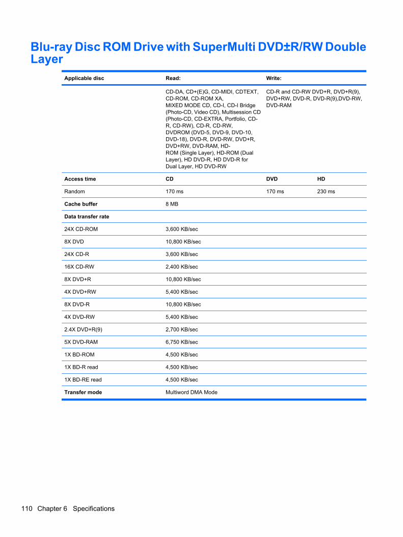
Blu-ray Disc ROM Drive with SuperMulti DVD±R/RW DoubleLayer
Applicable disc Read: Write:
CD-DA, CD+(E)G, CD-MIDI, CDTEXT,CD-ROM, CD-ROM XA,MIXED MODE CD, CD-I, CD-I Bridge(Photo-CD, Video CD), Multisession CD(Photo-CD, CD-EXTRA, Portfolio, CD-R, CD-RW), CD-R, CD-RW,DVDROM (DVD-5, DVD-9, DVD-10,DVD-18), DVD-R, DVD-RW, DVD+R,DVD+RW, DVD-RAM, HD-ROM (Single Layer), HD-ROM (DualLayer), HD DVD-R, HD DVD-R forDual Layer, HD DVD-RW
CD-R and CD-RW DVD+R, DVD+R(9),DVD+RW, DVD-R, DVD-R(9),DVD-RW,DVD-RAM
Access time CD DVD HD
Random 170 ms 170 ms 230 ms
Cache buffer 8 MB
Data transfer rate
24X CD-ROM 3,600 KB/sec
8X DVD 10,800 KB/sec
24X CD-R 3,600 KB/sec
16X CD-RW 2,400 KB/sec
8X DVD+R 10,800 KB/sec
4X DVD+RW 5,400 KB/sec
8X DVD-R 10,800 KB/sec
4X DVD-RW 5,400 KB/sec
2.4X DVD+R(9) 2,700 KB/sec
5X DVD-RAM 6,750 KB/sec
1X BD-ROM 4,500 KB/sec
1X BD-R read 4,500 KB/sec
1X BD-RE read 4,500 KB/sec
Transfer mode Multiword DMA Mode
110 Chapter 6 Specifications
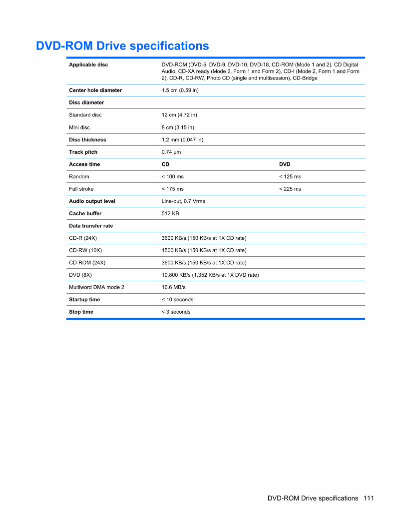
DVD-ROM Drive specificationsApplicable disc DVD-ROM (DVD-5, DVD-9, DVD-10, DVD-18, CD-ROM (Mode 1 and 2), CD Digital
Audio, CD-XA ready (Mode 2, Form 1 and Form 2), CD-I (Mode 2, Form 1 and Form2), CD-R, CD-RW, Photo CD (single and multisession), CD-Bridge
Center hole diameter 1.5 cm (0.59 in)
Disc diameter
Standard disc
Mini disc
12 cm (4.72 in)
8 cm (3.15 in)
Disc thickness 1.2 mm (0.047 in)
Track pitch 0.74 µm
Access time CD DVD
Random < 100 ms < 125 ms
Full stroke < 175 ms < 225 ms
Audio output level Line-out, 0.7 Vrms
Cache buffer 512 KB
Data transfer rate
CD-R (24X) 3600 KB/s (150 KB/s at 1X CD rate)
CD-RW (10X) 1500 KB/s (150 KB/s at 1X CD rate)
CD-ROM (24X) 3600 KB/s (150 KB/s at 1X CD rate)
DVD (8X) 10,800 KB/s (1,352 KB/s at 1X DVD rate)
Multiword DMA mode 2 16.6 MB/s
Startup time < 10 seconds
Stop time < 3 seconds
DVD-ROM Drive specifications 111
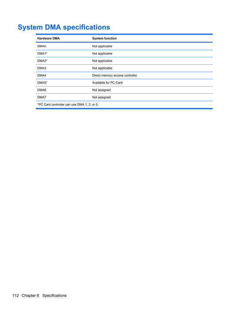
System DMA specificationsHardware DMA System function
DMA0 Not applicable
DMA1* Not applicable
DMA2* Not applicable
DMA3 Not applicable
DMA4 Direct memory access controller
DMA5* Available for PC Card
DMA6 Not assigned
DMA7 Not assigned
*PC Card controller can use DMA 1, 2, or 5.
112 Chapter 6 Specifications
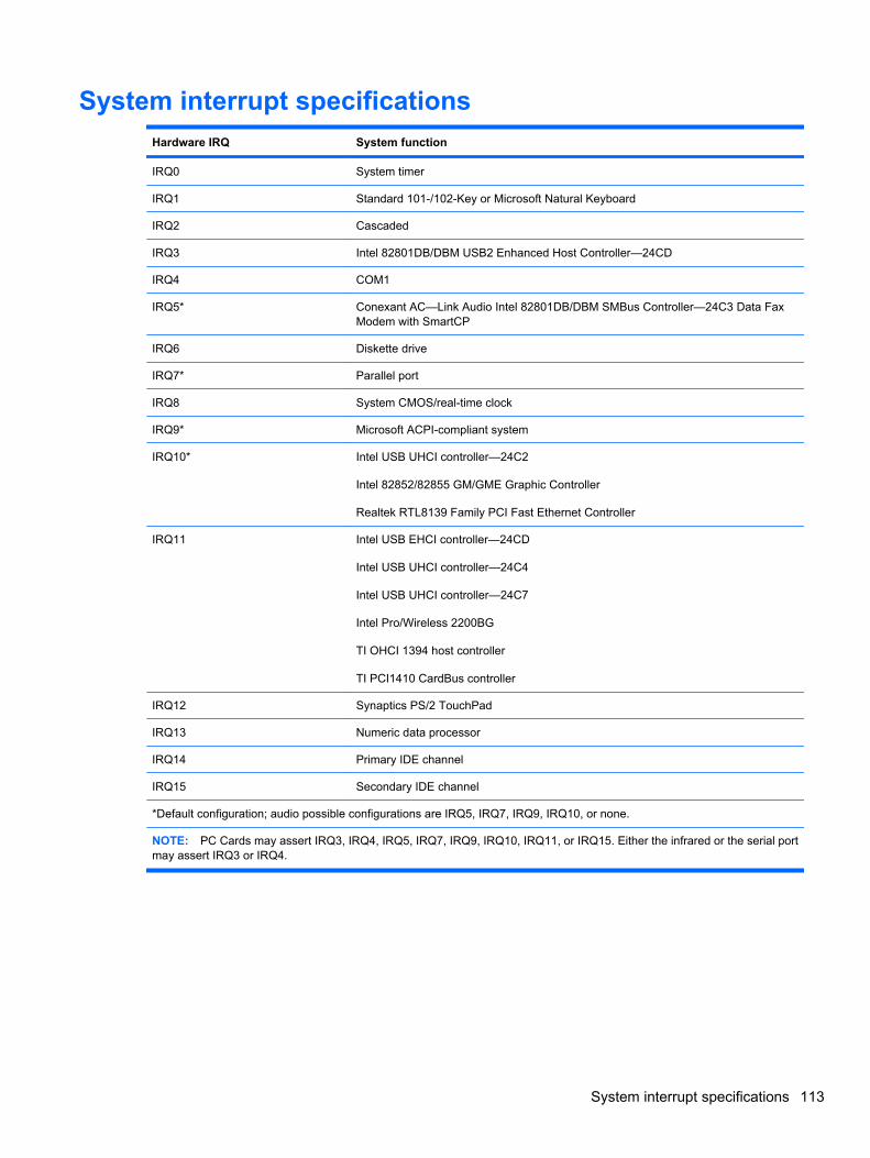
System interrupt specificationsHardware IRQ System function
IRQ0 System timer
IRQ1 Standard 101-/102-Key or Microsoft Natural Keyboard
IRQ2 Cascaded
IRQ3 Intel 82801DB/DBM USB2 Enhanced Host Controller—24CD
IRQ4 COM1
IRQ5* Conexant AC—Link Audio Intel 82801DB/DBM SMBus Controller—24C3 Data FaxModem with SmartCP
IRQ6 Diskette drive
IRQ7* Parallel port
IRQ8 System CMOS/real-time clock
IRQ9* Microsoft ACPI-compliant system
IRQ10* Intel USB UHCI controller—24C2
Intel 82852/82855 GM/GME Graphic Controller
Realtek RTL8139 Family PCI Fast Ethernet Controller
IRQ11 Intel USB EHCI controller—24CD
Intel USB UHCI controller—24C4
Intel USB UHCI controller—24C7
Intel Pro/Wireless 2200BG
TI OHCI 1394 host controller
TI PCI1410 CardBus controller
IRQ12 Synaptics PS/2 TouchPad
IRQ13 Numeric data processor
IRQ14 Primary IDE channel
IRQ15 Secondary IDE channel
*Default configuration; audio possible configurations are IRQ5, IRQ7, IRQ9, IRQ10, or none.
NOTE: PC Cards may assert IRQ3, IRQ4, IRQ5, IRQ7, IRQ9, IRQ10, IRQ11, or IRQ15. Either the infrared or the serial portmay assert IRQ3 or IRQ4.
System interrupt specifications 113
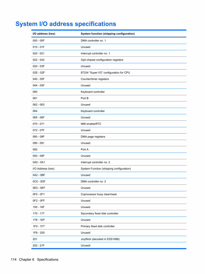
System I/O address specificationsI/O address (hex) System function (shipping configuration)
000 - 00F DMA controller no. 1
010 - 01F Unused
020 - 021 Interrupt controller no. 1
022 - 024 Opti chipset configuration registers
025 - 03F Unused
02E - 02F 87334 “Super I/O” configuration for CPU
040 - 05F Counter/timer registers
044 - 05F Unused
060 Keyboard controller
061 Port B
062 - 063 Unused
064 Keyboard controller
065 - 06F Unused
070 - 071 NMI enable/RTC
072 - 07F Unused
080 - 08F DMA page registers
090 - 091 Unused
092 Port A
093 - 09F Unused
0A0 - 0A1 Interrupt controller no. 2
I/O Address (hex) System Function (shipping configuration)
0A2 - 0BF Unused
0C0 - 0DF DMA controller no. 2
0E0 - 0EF Unused
0F0 - 0F1 Coprocessor busy clear/reset
0F2 - 0FF Unused
100 - 16F Unused
170 - 177 Secondary fixed disk controller
178 - 1EF Unused
1F0 - 1F7 Primary fixed disk controller
1F8 - 200 Unused
201 JoyStick (decoded in ESS1688)
202 - 21F Unused
114 Chapter 6 Specifications
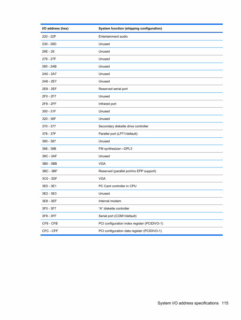
I/O address (hex) System function (shipping configuration)
220 - 22F Entertainment audio
230 - 26D Unused
26E - 26 Unused
278 - 27F Unused
280 - 2AB Unused
2A0 - 2A7 Unused
2A8 - 2E7 Unused
2E8 - 2EF Reserved serial port
2F0 - 2F7 Unused
2F8 - 2FF Infrared port
300 - 31F Unused
320 - 36F Unused
370 - 377 Secondary diskette drive controller
378 - 37F Parallel port (LPT1/default)
380 - 387 Unused
388 - 38B FM synthesizer—OPL3
38C - 3AF Unused
3B0 - 3BB VGA
3BC - 3BF Reserved (parallel port/no EPP support)
3C0 - 3DF VGA
3E0 - 3E1 PC Card controller in CPU
3E2 - 3E3 Unused
3E8 - 3EF Internal modem
3F0 - 3F7 “A” diskette controller
3F8 - 3FF Serial port (COM1/default)
CF8 - CFB PCI configuration index register (PCIDIVO-1)
CFC - CFF PCI configuration data register (PCIDIVO-1)
System I/O address specifications 115
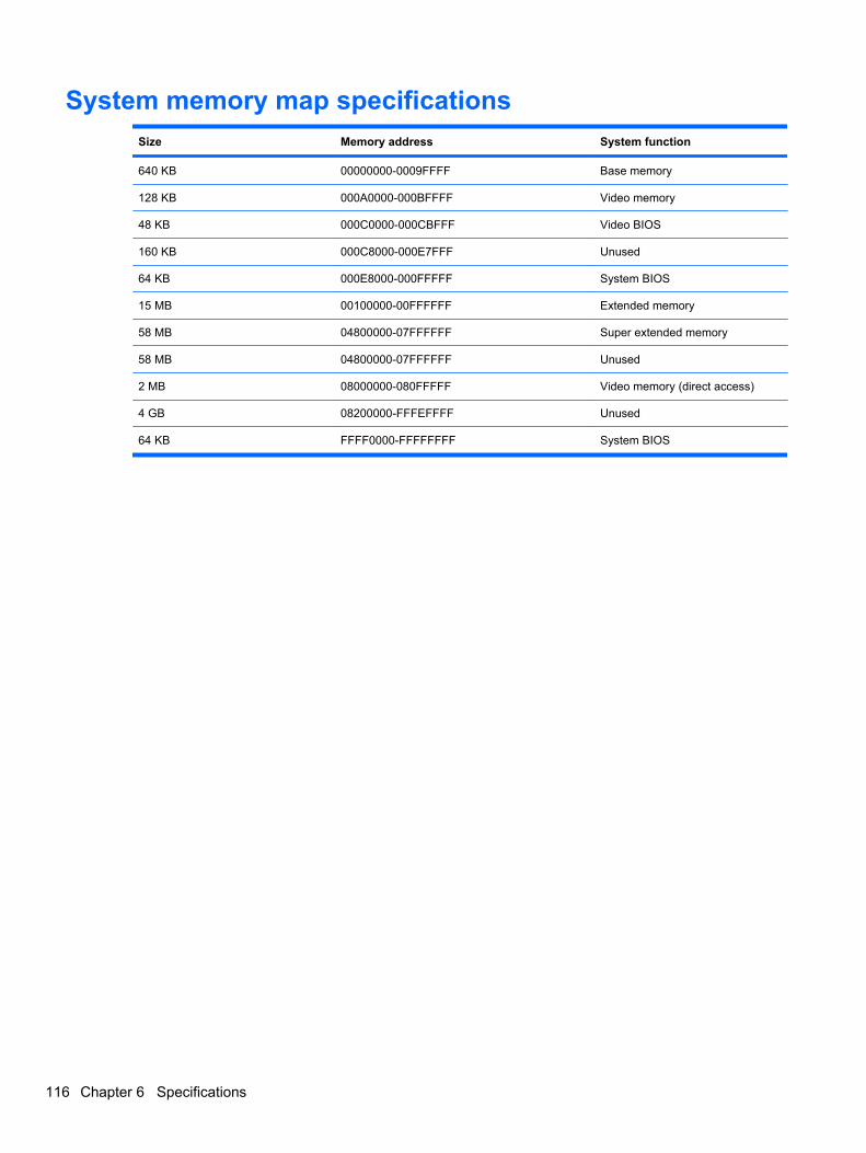
System memory map specificationsSize Memory address System function
640 KB 00000000-0009FFFF Base memory
128 KB 000A0000-000BFFFF Video memory
48 KB 000C0000-000CBFFF Video BIOS
160 KB 000C8000-000E7FFF Unused
64 KB 000E8000-000FFFFF System BIOS
15 MB 00100000-00FFFFFF Extended memory
58 MB 04800000-07FFFFFF Super extended memory
58 MB 04800000-07FFFFFF Unused
2 MB 08000000-080FFFFF Video memory (direct access)
4 GB 08200000-FFFEFFFF Unused
64 KB FFFF0000-FFFFFFFF System BIOS
116 Chapter 6 Specifications
7 Screw listing
This section provides specification and reference information for the screws and screw locks used inthe computer. All screws listed in this section are available in the Screw Kit, spare part number495077-001.
117
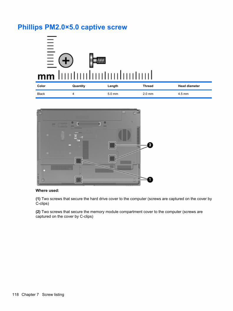
Phillips PM2.0×5.0 captive screw
Color Quantity Length Thread Head diameter
Black 4 5.0 mm 2.0 mm 4.5 mm
Where used:
(1) Two screws that secure the hard drive cover to the computer (screws are captured on the cover byC-clips)
(2) Two screws that secure the memory module compartment cover to the computer (screws arecaptured on the cover by C-clips)
118 Chapter 7 Screw listing
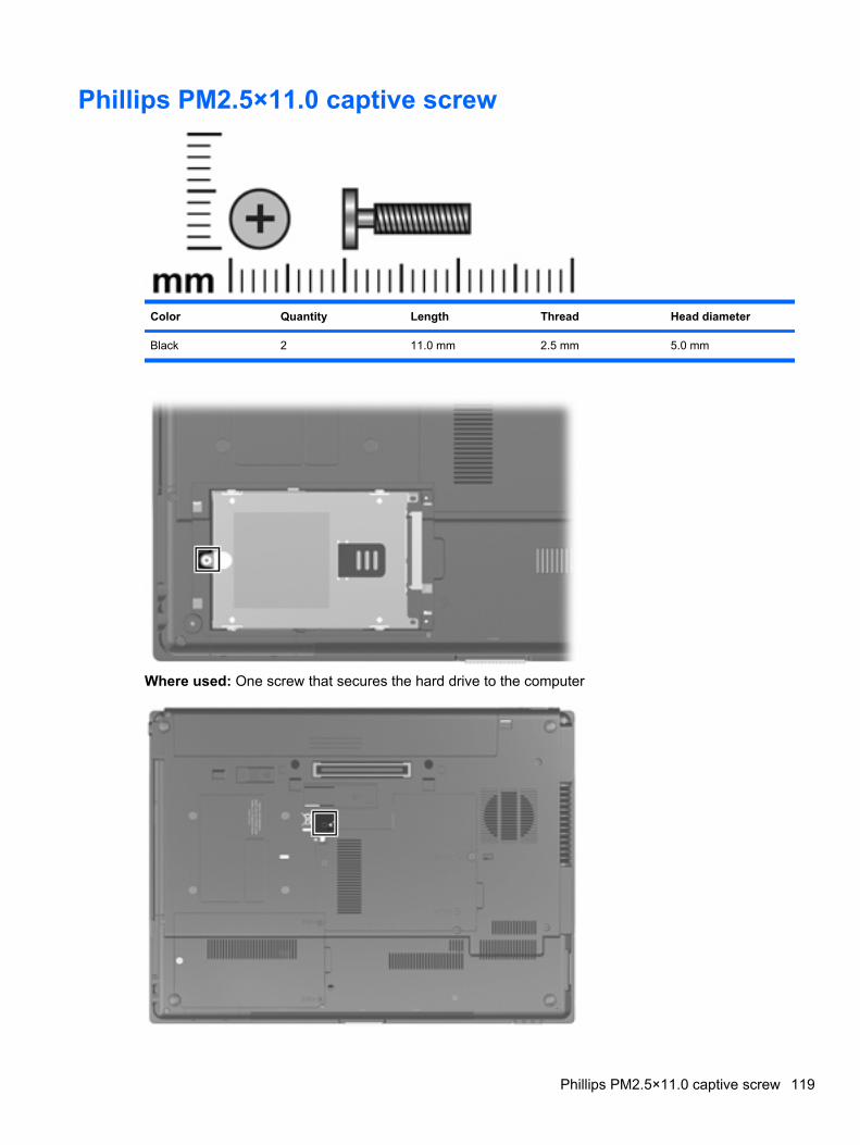
Phillips PM2.5×11.0 captive screw
Color Quantity Length Thread Head diameter
Black 2 11.0 mm 2.5 mm 5.0 mm
Where used: One screw that secures the hard drive to the computer
Phillips PM2.5×11.0 captive screw 119
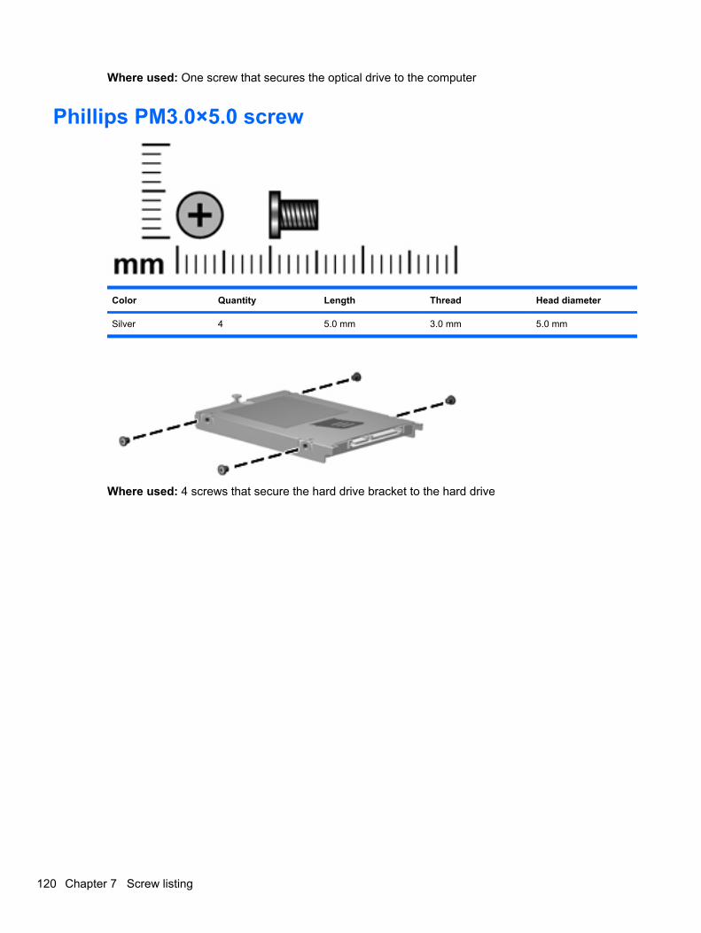
Where used: One screw that secures the optical drive to the computer
Phillips PM3.0×5.0 screw
Color Quantity Length Thread Head diameter
Silver 4 5.0 mm 3.0 mm 5.0 mm
Where used: 4 screws that secure the hard drive bracket to the hard drive
120 Chapter 7 Screw listing
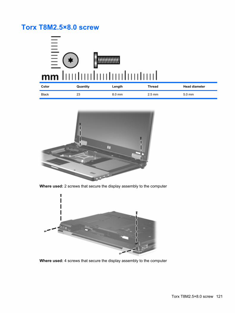
Torx T8M2.5×8.0 screw
Color Quantity Length Thread Head diameter
Black 23 8.0 mm 2.5 mm 5.0 mm
Where used: 2 screws that secure the display assembly to the computer
Where used: 4 screws that secure the display assembly to the computer
Torx T8M2.5×8.0 screw 121
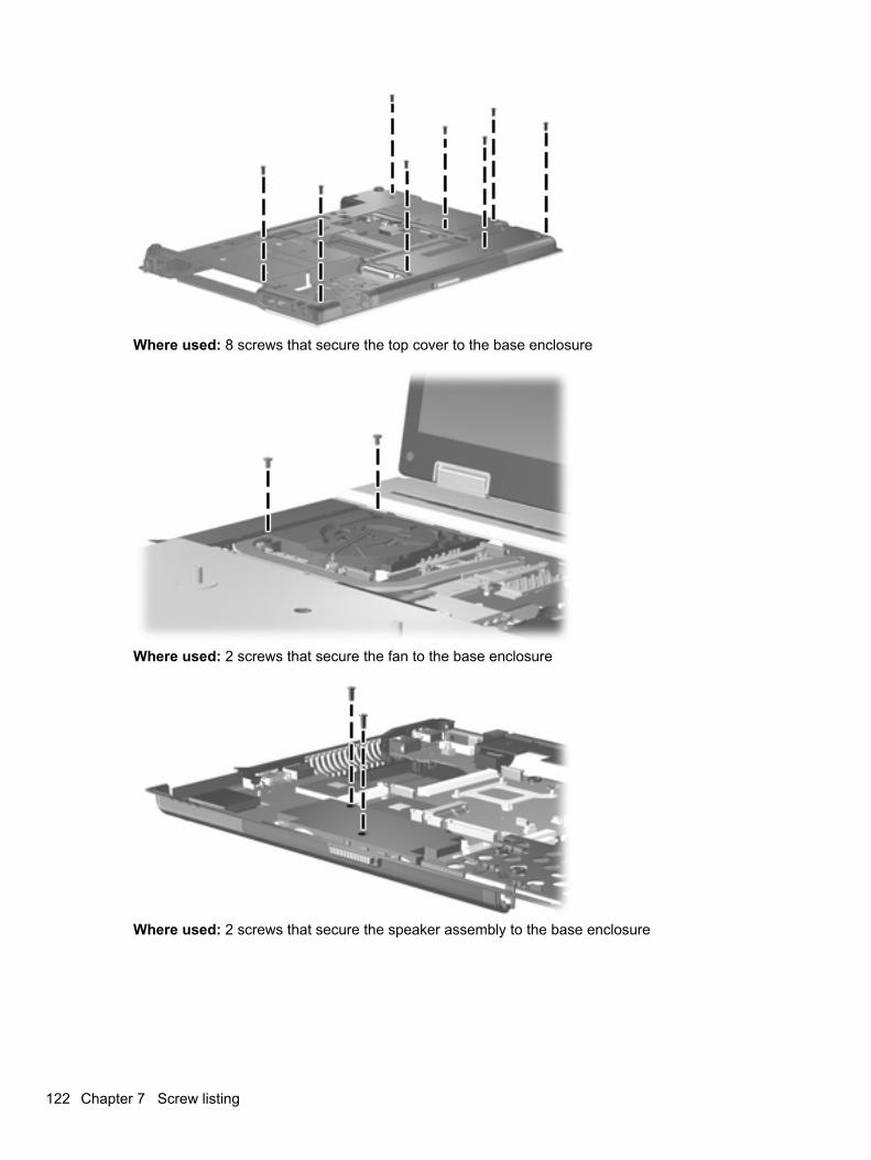
Where used: 8 screws that secure the top cover to the base enclosure
Where used: 2 screws that secure the fan to the base enclosure
Where used: 2 screws that secure the speaker assembly to the base enclosure
122 Chapter 7 Screw listing
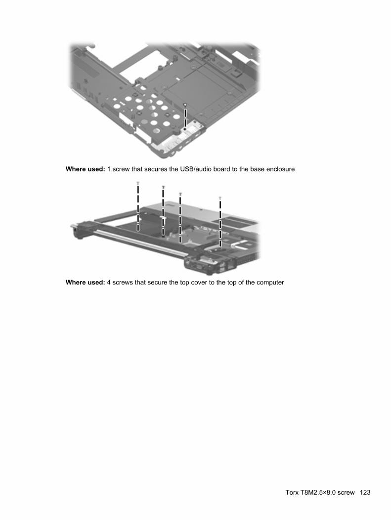
Where used: 1 screw that secures the USB/audio board to the base enclosure
Where used: 4 screws that secure the top cover to the top of the computer
Torx T8M2.5×8.0 screw 123
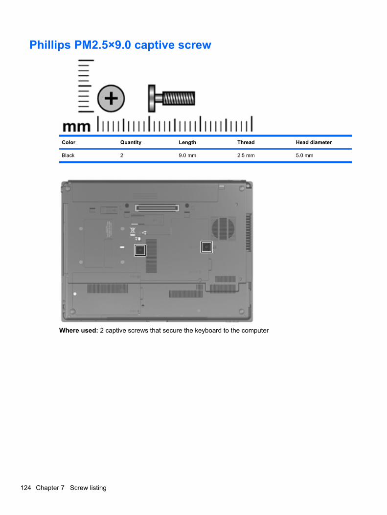
Phillips PM2.5×9.0 captive screw
Color Quantity Length Thread Head diameter
Black 2 9.0 mm 2.5 mm 5.0 mm
Where used: 2 captive screws that secure the keyboard to the computer
124 Chapter 7 Screw listing
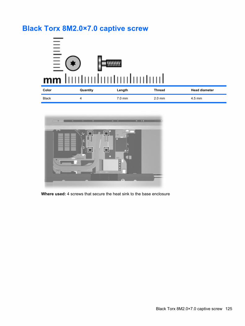
Black Torx 8M2.0×7.0 captive screw
Color Quantity Length Thread Head diameter
Black 4 7.0 mm 2.0 mm 4.5 mm
Where used: 4 screws that secure the heat sink to the base enclosure
Black Torx 8M2.0×7.0 captive screw 125
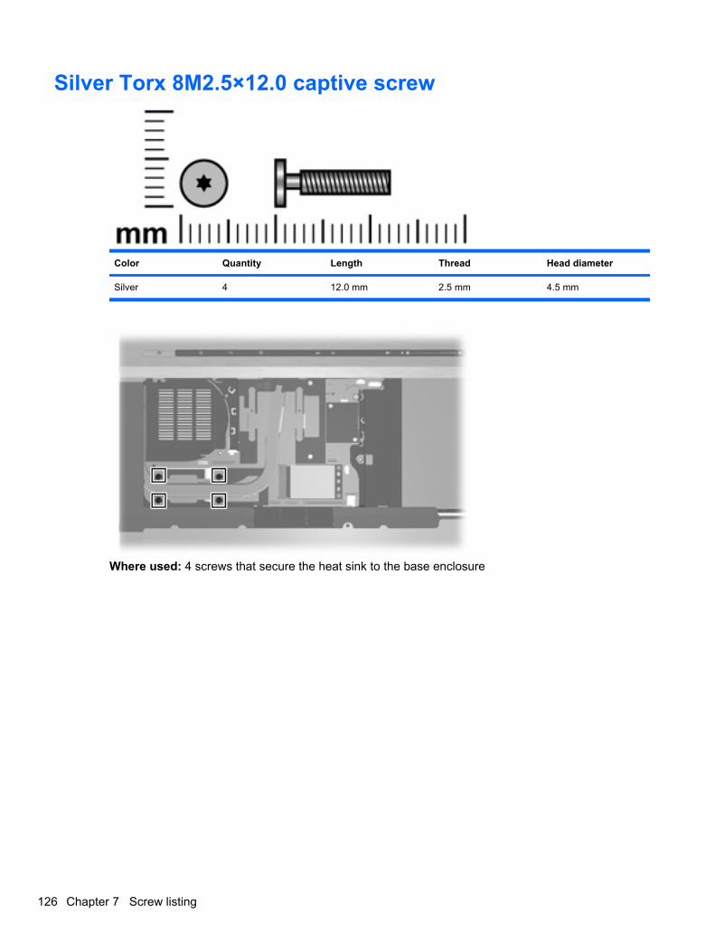
Silver Torx 8M2.5×12.0 captive screw
Color Quantity Length Thread Head diameter
Silver 4 12.0 mm 2.5 mm 4.5 mm
Where used: 4 screws that secure the heat sink to the base enclosure
126 Chapter 7 Screw listing
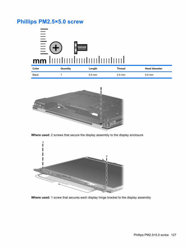
Phillips PM2.5×5.0 screw
Color Quantity Length Thread Head diameter
Black 7 5.0 mm 2.5 mm 5.0 mm
Where used: 2 screws that secure the display assembly to the display enclosure
Where used: 1 screw that secures each display hinge bracket to the display assembly
Phillips PM2.5×5.0 screw 127
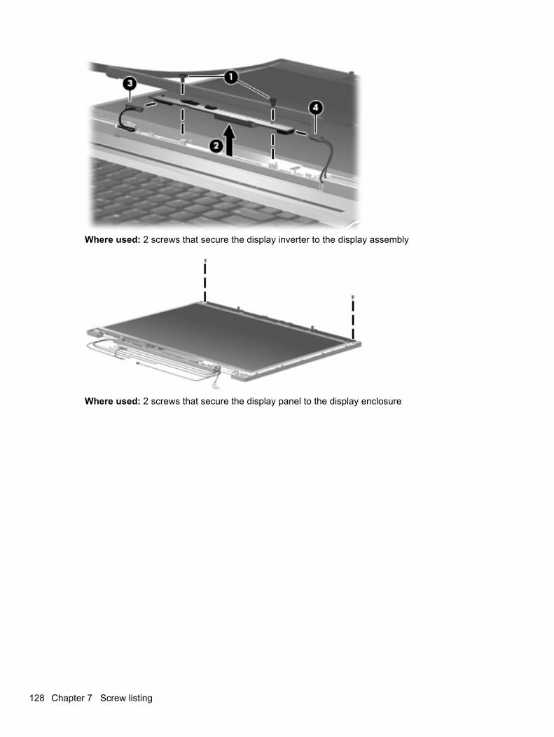
Where used: 2 screws that secure the display inverter to the display assembly
Where used: 2 screws that secure the display panel to the display enclosure
128 Chapter 7 Screw listing
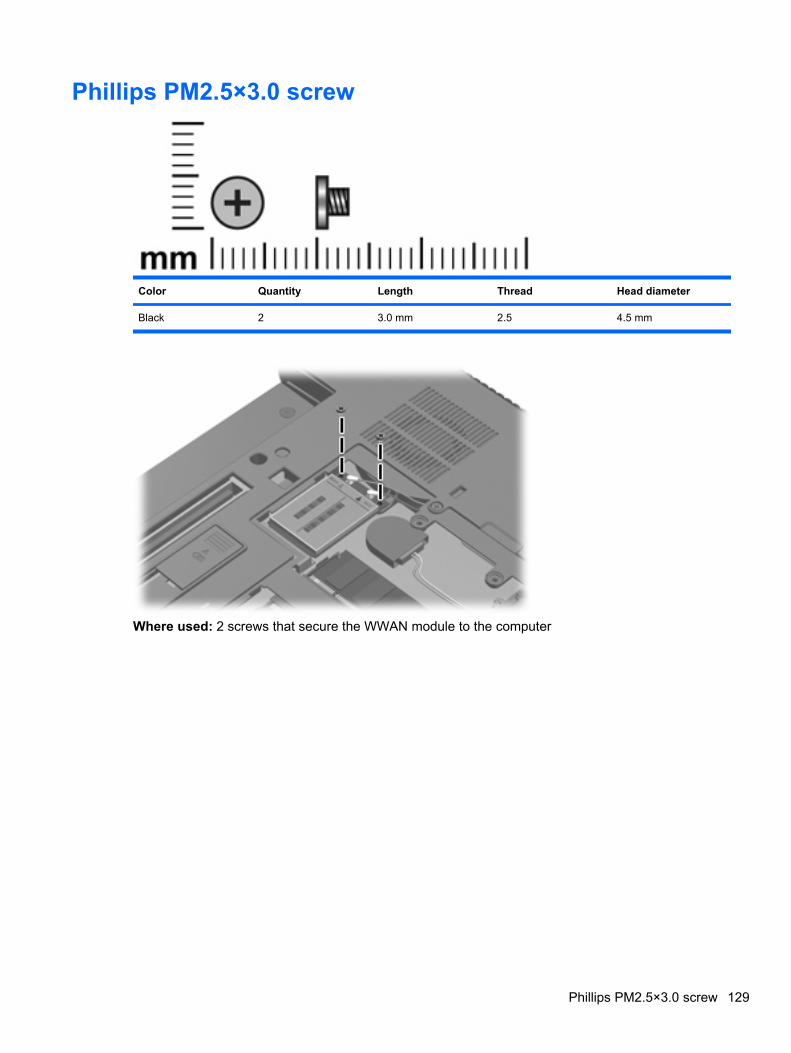
Phillips PM2.5×3.0 screw
Color Quantity Length Thread Head diameter
Black 2 3.0 mm 2.5 4.5 mm
Where used: 2 screws that secure the WWAN module to the computer
Phillips PM2.5×3.0 screw 129
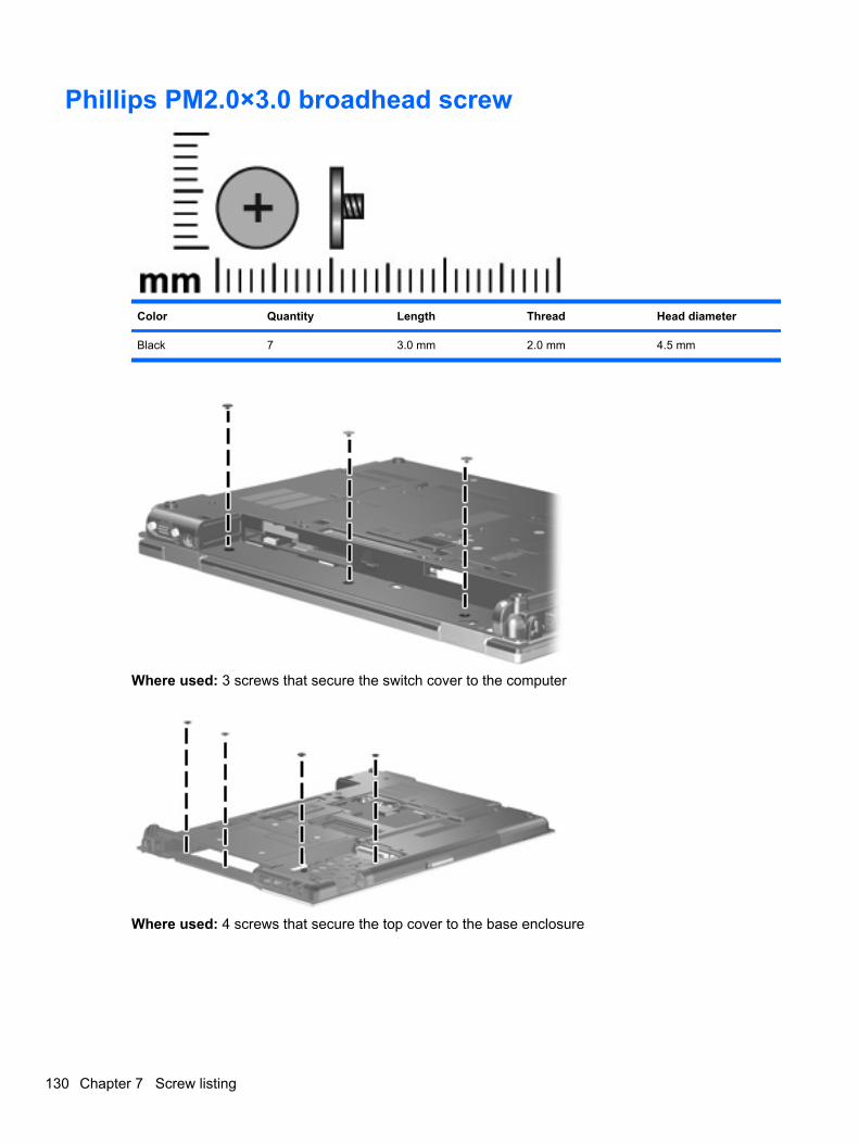
Phillips PM2.0×3.0 broadhead screw
Color Quantity Length Thread Head diameter
Black 7 3.0 mm 2.0 mm 4.5 mm
Where used: 3 screws that secure the switch cover to the computer
Where used: 4 screws that secure the top cover to the base enclosure
130 Chapter 7 Screw listing
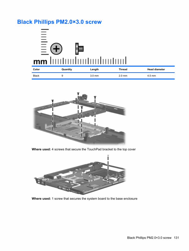
Black Phillips PM2.0×3.0 screw
Color Quantity Length Thread Head diameter
Black 9 3.0 mm 2.0 mm 4.5 mm
Where used: 4 screws that secure the TouchPad bracket to the top cover
Where used: 1 screw that secures the system board to the base enclosure
Black Phillips PM2.0×3.0 screw 131
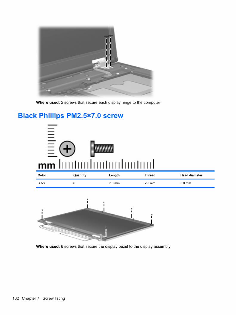
Where used: 2 screws that secure each display hinge to the computer
Black Phillips PM2.5×7.0 screw
Color Quantity Length Thread Head diameter
Black 6 7.0 mm 2.5 mm 5.0 mm
Where used: 6 screws that secure the display bezel to the display assembly
132 Chapter 7 Screw listing
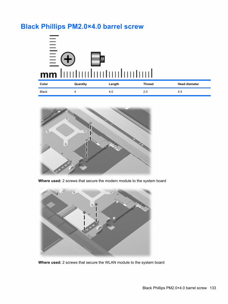
Black Phillips PM2.0×4.0 barrel screw
Color Quantity Length Thread Head diameter
Black 4 4.0 2.0 4.5
Where used: 2 screws that secure the modem module to the system board
Where used: 2 screws that secure the WLAN module to the system board
Black Phillips PM2.0×4.0 barrel screw 133
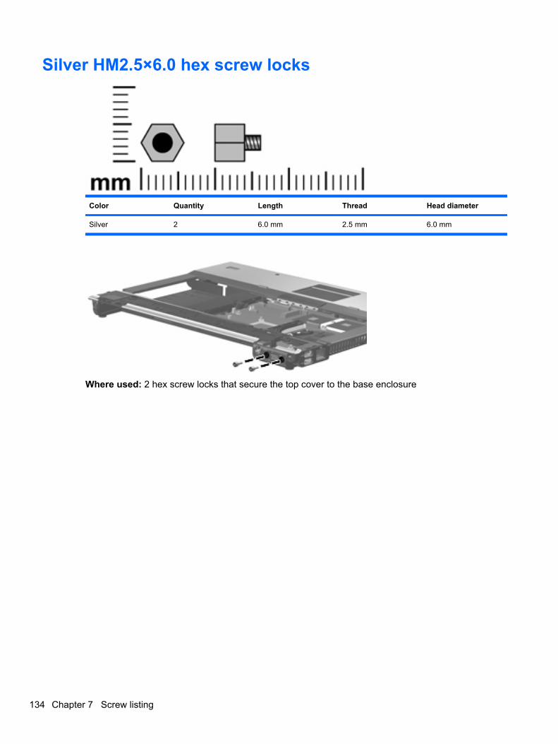
Silver HM2.5×6.0 hex screw locks
Color Quantity Length Thread Head diameter
Silver 2 6.0 mm 2.5 mm 6.0 mm
Where used: 2 hex screw locks that secure the top cover to the base enclosure
134 Chapter 7 Screw listing
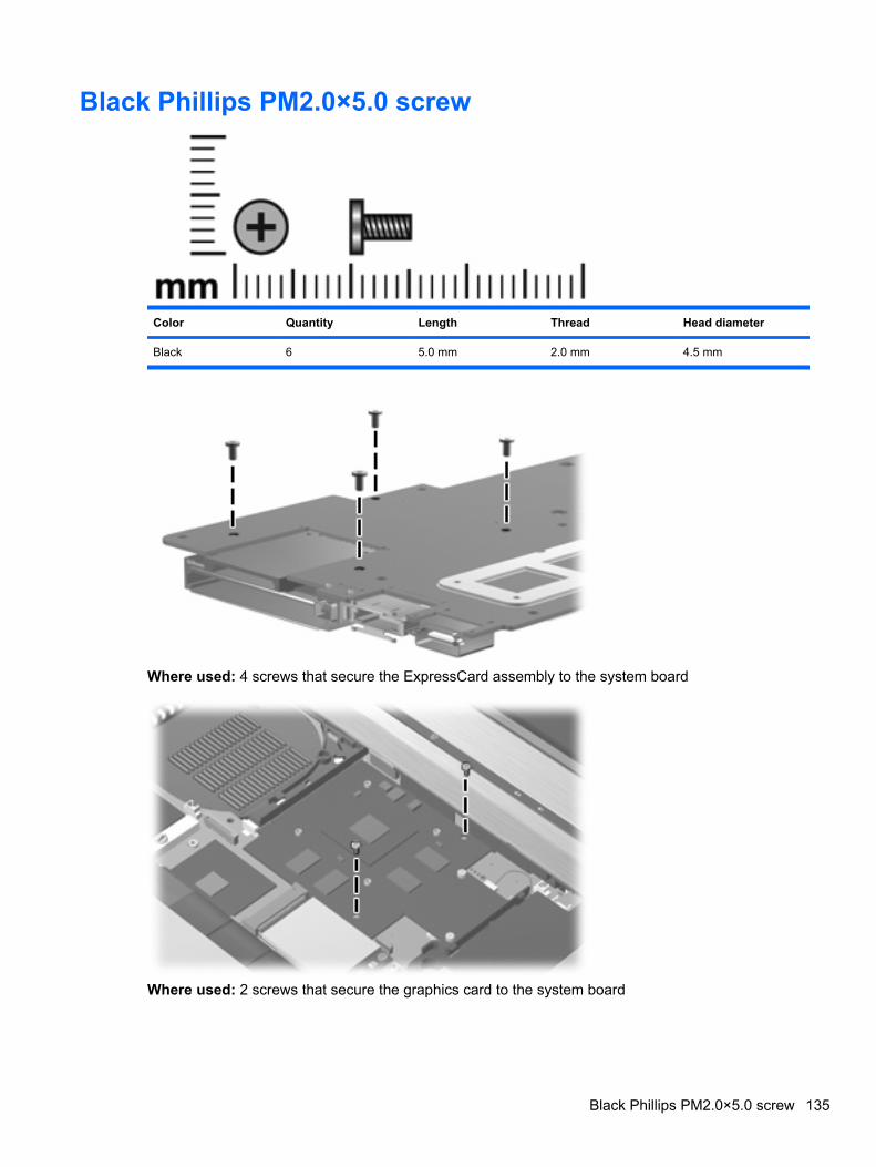
Black Phillips PM2.0×5.0 screw
Color Quantity Length Thread Head diameter
Black 6 5.0 mm 2.0 mm 4.5 mm
Where used: 4 screws that secure the ExpressCard assembly to the system board
Where used: 2 screws that secure the graphics card to the system board
Black Phillips PM2.0×5.0 screw 135
8 Backup and recovery
Backup and recovery in Windows VistaOverview
To protect your information, use the Backup and Restore Center to back up individual files and folders,back up your entire hard drive (select models only), or create system restore points. In case of systemfailure, you can use the backup files to restore the contents of your computer.
The Backup and Restore Center provides the following options:
● Backing up individual files and folders
● Backing up the entire hard drive (select models only)
● Scheduling automatic backups (select models only)
● Creating system restore points
● Recovering individual files
● Restoring the computer to a previous state
● Recovering information using recovery tools
NOTE: For detailed instructions, perform a search for these topics in Help and Support.
NOTE: In case of system instability, HP recommends that you print the recovery procedures and savethem for later use.
Backing up your informationRecovery after a system failure is as complete as your most current backup. You should create yourinitial backup immediately after software setup. As you add new software and data files, you shouldcontinue to back up your system on a regular basis to maintain a reasonably current backup.
You can back up your information to an optional external hard drive, a network drive, or discs.
Note the following when backing up:
● Store personal files in the Documents folder, and back it up regularly.
● Back up templates that are stored in their associated programs.
● Save customized settings that appear in a window, toolbar, or menu bar by taking a screen shotof your settings. The screen shot can be a time-saver if you have to reset your preferences.
136 Chapter 8 Backup and recovery
To create a screen shot:
1. Display the screen you want to save.
2. Copy the screen image:
To copy only the active window, press alt+fn+prt sc.
To copy the entire screen, press fn+prt sc.
3. Open a word-processing document, and then select Edit > Paste.
The screen image is added to the document.
4. Save the document.
● When backing up to discs, use any of the following types of discs (purchased separately): CD-R,CD-RW, DVD+R, DVD+R DL, DVD-R, DVD-R DL, or DVD±RW. The discs you use will depend onthe type of optical drive installed in your computer.
NOTE: DVDs and DVDs with double-layer (DL) support store more information than CDs, sousing them for backup reduces the number of recovery discs required.
● When backing up to discs, number each disc before inserting it into the optical drive of the computer.
To create a backup using Backup and Restore Center, follow these steps:
NOTE: Be sure that the computer is connected to AC power before you start the backup process.
NOTE: The backup process may take over an hour, depending on file size and the speed of thecomputer.
1. Select Start > All Programs > Maintenance > Backup and Restore Center.
2. Follow the on-screen instructions to back up your entire computer (select models only) or your files.
NOTE: Windows® includes the User Account Control feature to improve the security of yourcomputer. You may be prompted for your permission or password for tasks such as installingsoftware, running utilities, or changing Windows settings. Refer to Help and Support for moreinformation.
Performing a recoveryIn case of system failure or instability, the computer provides the following tools to recover your files:
● Windows recovery tools: You can use the Backup and Restore Center to recover information youhave previously backed up. You can also use Windows Startup Repair to fix problems that mightprevent Windows from starting correctly.
● f11 recovery tools: You can use the f11 recovery tools to recover your original hard drive image.The image includes the Windows operating system and software programs installed at the factory.
NOTE: If you are unable to boot (start up) your computer, you must purchase a Windows Vistaoperating system DVD to reboot the computer and repair the operating system. For additionalinformation, refer to the “Using a Windows Vista operating system DVD (purchased separately)” sectionin this guide.
Backup and recovery in Windows Vista 137
Using the Windows recovery toolsTo recover information you previously backed up, follow these steps:
1. Click Start > All Programs > Maintenance > Backup and Restore Center.
2. Follow the on-screen instructions to recover your entire computer (select models only) or your files.
NOTE: Windows includes the User Account Control feature to improve the security of your computer.You may be prompted for your permission or password for tasks such as installing software, runningutilities, or changing Windows settings. Refer to Help and Support for more information.
To recover your information using Startup Repair, follow these steps:
CAUTION: Using Startup Repair completely erases hard drive contents and reformats the hard drive.All files you have created and any software installed on the computer are permanently removed. Whenreformatting is complete, the recovery process restores the operating system, as well as the drivers,software, and utilities from the backup used for recovery.
1. If possible, back up all personal files.
2. If possible, check for the presence of the Windows partition and the HP Recovery partition. To findthe partitions, select Start > Computer.
NOTE: If the Windows partition and the HP Recovery partition have been deleted, you mustrecover your operating system and programs using the Windows Vista operating system DVD andthe Driver Recovery disc (both purchased separately). For additional information, refer to the “Usinga Windows Vista operating system DVD (purchased separately)” section in this guide.
3. Restart the computer, and then press f8 before the Windows operating system loads.
4. Select Repair your computer.
5. Follow the on-screen instructions.
NOTE: For additional information on recovering information using the Windows tools, perform a searchfor these topics in Help and Support.
Using f11CAUTION: Using f11 completely erases hard drive contents and reformats the hard drive. All files youhave created and any software installed on the computer are permanently removed. The f11 recoverytool reinstalls the operating system and HP programs and drivers that were installed at the factory.Software not installed at the factory must be reinstalled.
To recover the original hard drive image using f11, follow these steps:
1. If possible, back up all personal files.
2. If possible, check for the presence of the HP Recovery partition. To find the partition, selectStart > Computer.
NOTE: If the HP Recovery partition has been deleted, you must recover your operating systemand programs using the Windows Vista operating system DVD and the Driver Recovery disc (bothpurchased separately). For additional information, refer to the “Using a Windows Vista operatingsystem DVD (purchased separately)” section in this guide.
3. Turn on or restart the computer, and then press esc while the “Press the ESC key for Startup Menu”message is displayed at the bottom of the screen.
138 Chapter 8 Backup and recovery
4. Press f11 while the “Press <F11> for recovery” message is displayed on the screen.
5. Follow the on-screen instructions.
Using a Windows Vista operating system DVD (purchased separately)If you are unable to boot (start up) your computer, you must purchase a Windows Vista operating systemDVD to reboot the computer and repair the operating system. Make sure that your most recent backup(stored on discs or on an external drive) is easily accessible. To order a Windows Vista operating systemDVD, go to http://www.hp.com/support, select your country or region, and follow the on-screeninstructions. You can also order the DVD by calling technical support. For contact information, refer tothe Worldwide Telephone Numbers booklet included with the computer.
CAUTION: Using a Windows Vista operating system DVD completely erases hard drive contents andreformats the hard drive. All files you have created and any software installed on the computer arepermanently removed. When reformatting is complete, the recovery process helps you restore theoperating system, as well as drivers, software, and utilities.
To initiate recovery using a Windows Vista operating system DVD, follow these steps:
NOTE: This process takes several minutes.
1. If possible, back up all personal files.
2. Restart the computer, and then insert the Windows Vista operating system DVD into the opticaldrive before the Windows operating system loads.
3. When prompted, press any keyboard key.
4. Follow the on-screen instructions.
5. Click Next.
6. Select Repair your computer.
7. Follow the on-screen instructions.
Backup and Recovery in Windows XPBacking up your information
NOTE: You can recover only the files that you have previously backed up. HP recommends that youuse the Windows backup utility to create a hard drive backup as soon as you set up your computer.
With the Windows backup utility, you can perform the following tasks:
● Backing up your information regularly to protect your important system files
● Creating system recovery points that allow you to reverse undesirable changes to your computerby restoring the computer to an earlier state
● Scheduling backups at specific intervals or events
NOTE: The Windows backup utility backs up only data files. The operating system, drivers, andprograms are located on the operating system disc and System Recovery disc that are included withthe computer.
Backup and Recovery in Windows XP 139
When to back up
● On a regularly scheduled basis
NOTE: Set reminders to back up your information periodically.
● Before the computer is repaired or restored
● Before you add or modify hardware or software
Backup suggestions
● Connect the computer to external power before performing backup and recovery procedures.
● Create system recovery points.
● Store personal files in the My Documents folder and back up these folders periodically.
● Back up templates stored in their associated programs.
● Save customized settings that appear in a window, toolbar, or menu bar by taking a screen shotof your settings. The screen shot can be a time saver if you have to reset your preferences.
To copy the screen and paste it into a word-processing document:
a. Display the screen you want to save.
b. Copy the screen image:
To copy only the active window, press alt+fn+prt sc.
To copy the entire screen, press fn+prt sc.
c. Open a word-processing document, click Edit > Paste.
The screen image is added to the document.
d. Save the document.
Backing up individual files or foldersYou can back up individual files or folders to an optional external hard drive or to a network drive.
NOTE: This process will take several minutes, depending on the file size and the speed of thecomputer.
To back up individual files or folders:
1. Select Start > All Programs > Accessories > System Tools > Backup.
The Backup or Restore Wizard page opens.
2. Click Next.
3. Click Backup files and settings, and then click Next.
4. Follow the on-screen instructions.
140 Chapter 8 Backup and recovery
Backing up all files and foldersWhen you back up all files and folders, you are saving all personal files and folders, all system files, andconfiguration settings at one time.
NOTE: When you back up all files and folders, this does not include the operating system or programs.
NOTE: This process may take over an hour, depending on your computer speed and the amount ofdata being stored.
NOTE: A copy of the backup files can be stored on an optional external hard drive or on a networkdrive.
To back up all files and folders:
1. Select Start > All Programs > Accessories > System Tools > Backup.
The Backup or Restore Wizard page opens.
2. Click Next.
3. Click Backup files and settings, and then click Next.
4. Click All information on this computer, and then click Next.
5. Follow the on-screen instructions.
Creating recovery pointsWhen you back up system modifications since your last backup, you are creating system recoverypoints. This allows you to save a snapshot of your hard drive at a specific point in time. You can thenrecover back to that point if you want to reverse subsequent changes made to your system.
NOTE: The first system recovery point, a snapshot of the entire image, is automatically created thefirst time you perform a backup. Subsequent recovery points make copies of changes made after thattime.
HP recommends that you create recovery points at the following times:
● Before you add or extensively modify software or hardware
● Periodically, whenever the system is performing optimally
NOTE: Recovering to an earlier recovery point does not affect data files or e-mails created since thatrecovery point.
To create a system recovery point:
1. Select Start > All Programs > Accessories > System Tools > System Restore.
The System Restore window opens.
2. Click Create a new restore point, and then click Next.
3. Type a short description of the restore point. This will be used as the name of the restore point.
4. Click Create.
5. Follow the on-screen instructions.
Backup and Recovery in Windows XP 141
Scheduling backupsYou can schedule backups for the entire system, for recovery points, or for specific files and folders.Backups can be scheduled at specific intervals (daily, weekly, or monthly) or at specific events, such asat system restart or when you log on.
To schedule backups:
1. Select Start > All Programs > Accessories > System Tools > Schedule Tasks.
The Schedule Tasks window opens.
2. Double-click Add Scheduled Task, and then click Next.
3. Select Backup in the Application list, and then click Next.
4. Type a name for the backup, select when you want the backup to be performed, and then clickNext.
5. Enter your user name, password, and password again to confirm. Click Next, and then clickFinish.
Performing a recoveryThe Windows backup utility helps you recover important files that you have previously backed up incase of system failure.
NOTE: To recover the operating system and programs, use the operating system disc and SystemRestore disc that are included with the computer.
Initiating a recovery in WindowsTo initiate a recovery in Windows, follow these steps:
1. If possible, back up all personal files.
2. Select Start > All Programs > Accessories > System Tools > Backup.
The Backup or Restore Wizard page opens.
3. Click Restore files and settings, and the click Next.
4. Follow the on-screen instructions.
142 Chapter 8 Backup and recovery
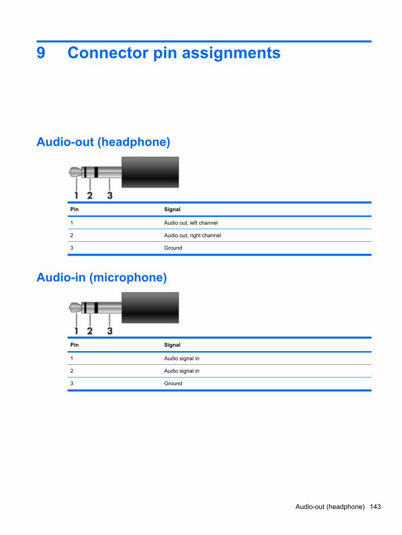
9 Connector pin assignments
Audio-out (headphone)
Pin Signal
1 Audio out, left channel
2 Audio out, right channel
3 Ground
Audio-in (microphone)
Pin Signal
1 Audio signal in
2 Audio signal in
3 Ground
Audio-out (headphone) 143

External monitor
Pin Signal
1 Red analog
2 Green analog
3 Blue analog
4 Not connected
5 Ground
6 Ground analog
7 Ground analog
8 Ground analog
9 +5 VDC
10 Ground
11 Monitor detect
12 DDC 2B data
13 Horizontal sync
14 Vertical sync
15 DDC 2B clock
144 Chapter 9 Connector pin assignments
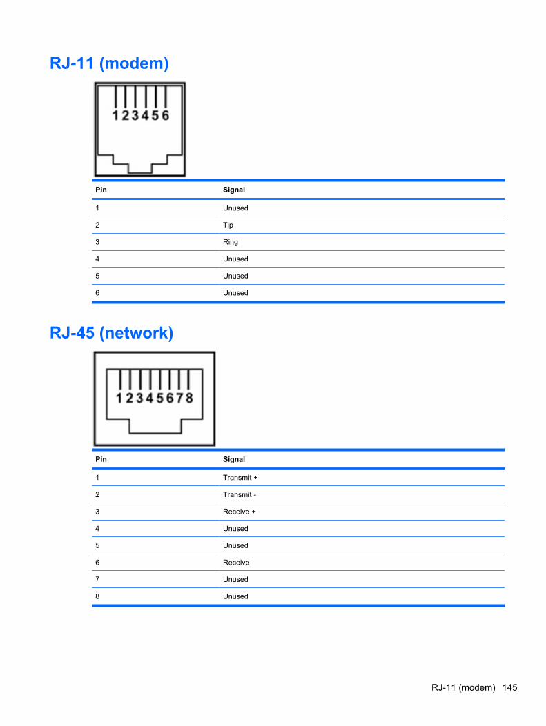
RJ-11 (modem)
Pin Signal
1 Unused
2 Tip
3 Ring
4 Unused
5 Unused
6 Unused
RJ-45 (network)
Pin Signal
1 Transmit +
2 Transmit -
3 Receive +
4 Unused
5 Unused
6 Receive -
7 Unused
8 Unused
RJ-11 (modem) 145
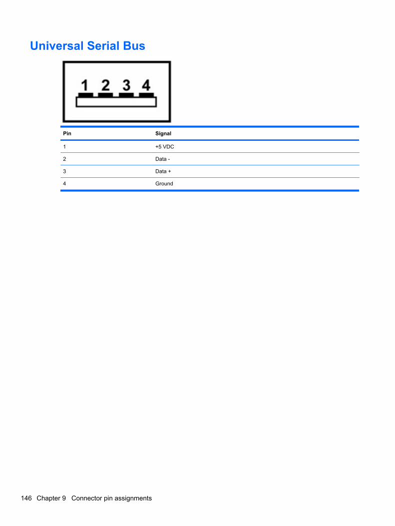
Universal Serial Bus
Pin Signal
1 +5 VDC
2 Data -
3 Data +
4 Ground
146 Chapter 9 Connector pin assignments

10 Power cord set requirements
The wide range input feature of the computer permits it to operate from any line voltage from 100 to 120volts AC or from 220 to 240 volts AC.
The 3-conductor power cord set included with the computer meets the requirements for use in thecountry or region where the equipment is purchased.
Power cord sets for use in other countries and regions must meet the requirements of the country orregion where the computer is used.
Requirements for all countries and regionsThe requirements listed below are applicable to all countries and regions:
● The length of the power cord set must be at least 1.5 m (5.0 ft) and no more than 2.0 m (6.5 ft).
● All power cord sets must be approved by an acceptable accredited agency responsible forevaluation in the country or region where the power cord set will be used.
● The power cord sets must have a minimum current capacity of 10 amps and a nominal voltagerating of 125 or 250 V AC, as required by the power system of each country or region.
● The appliance coupler must meet the mechanical configuration of an EN 60 320/IEC 320 StandardSheet C13 connector for mating with the appliance inlet on the back of the computer.
Requirements for all countries and regions 147
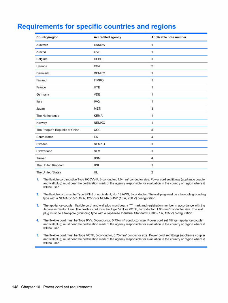
Requirements for specific countries and regionsCountry/region Accredited agency Applicable note number
Australia EANSW 1
Austria OVE 1
Belgium CEBC 1
Canada CSA 2
Denmark DEMKO 1
Finland FIMKO 1
France UTE 1
Germany VDE 1
Italy IMQ 1
Japan METI 3
The Netherlands KEMA 1
Norway NEMKO 1
The People's Republic of China CCC 5
South Korea EK 4
Sweden SEMKO 1
Switzerland SEV 1
Taiwan BSMI 4
The United Kingdom BSI 1
The United States UL 2
1. The flexible cord must be Type HO5VV-F, 3-conductor, 1.0-mm² conductor size. Power cord set fittings (appliance couplerand wall plug) must bear the certification mark of the agency responsible for evaluation in the country or region where itwill be used.
2. The flexible cord must be Type SPT-3 or equivalent, No. 18 AWG, 3-conductor. The wall plug must be a two-pole groundingtype with a NEMA 5-15P (15 A, 125 V) or NEMA 6-15P (15 A, 250 V) configuration.
3. The appliance coupler, flexible cord, and wall plug must bear a “T” mark and registration number in accordance with theJapanese Dentori Law. The flexible cord must be Type VCT or VCTF, 3-conductor, 1.00-mm² conductor size. The wallplug must be a two-pole grounding type with a Japanese Industrial Standard C8303 (7 A, 125 V) configuration.
4. The flexible cord must be Type RVV, 3-conductor, 0.75-mm² conductor size. Power cord set fittings (appliance couplerand wall plug) must bear the certification mark of the agency responsible for evaluation in the country or region where itwill be used.
5. The flexible cord must be Type VCTF, 3-conductor, 0.75-mm² conductor size. Power cord set fittings (appliance couplerand wall plug) must bear the certification mark of the agency responsible for evaluation in the country or region where itwill be used.
148 Chapter 10 Power cord set requirements
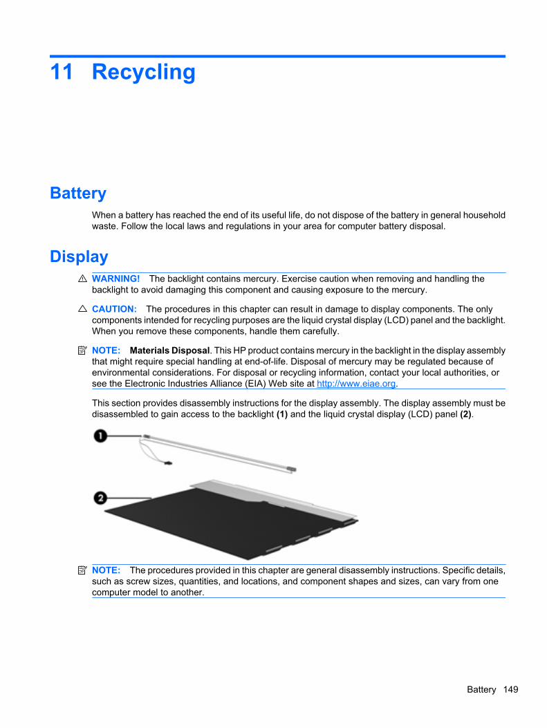
11 Recycling
BatteryWhen a battery has reached the end of its useful life, do not dispose of the battery in general householdwaste. Follow the local laws and regulations in your area for computer battery disposal.
DisplayWARNING! The backlight contains mercury. Exercise caution when removing and handling thebacklight to avoid damaging this component and causing exposure to the mercury.
CAUTION: The procedures in this chapter can result in damage to display components. The onlycomponents intended for recycling purposes are the liquid crystal display (LCD) panel and the backlight.When you remove these components, handle them carefully.
NOTE: Materials Disposal. This HP product contains mercury in the backlight in the display assemblythat might require special handling at end-of-life. Disposal of mercury may be regulated because ofenvironmental considerations. For disposal or recycling information, contact your local authorities, orsee the Electronic Industries Alliance (EIA) Web site at http://www.eiae.org.
This section provides disassembly instructions for the display assembly. The display assembly must bedisassembled to gain access to the backlight (1) and the liquid crystal display (LCD) panel (2).
NOTE: The procedures provided in this chapter are general disassembly instructions. Specific details,such as screw sizes, quantities, and locations, and component shapes and sizes, can vary from onecomputer model to another.
Battery 149
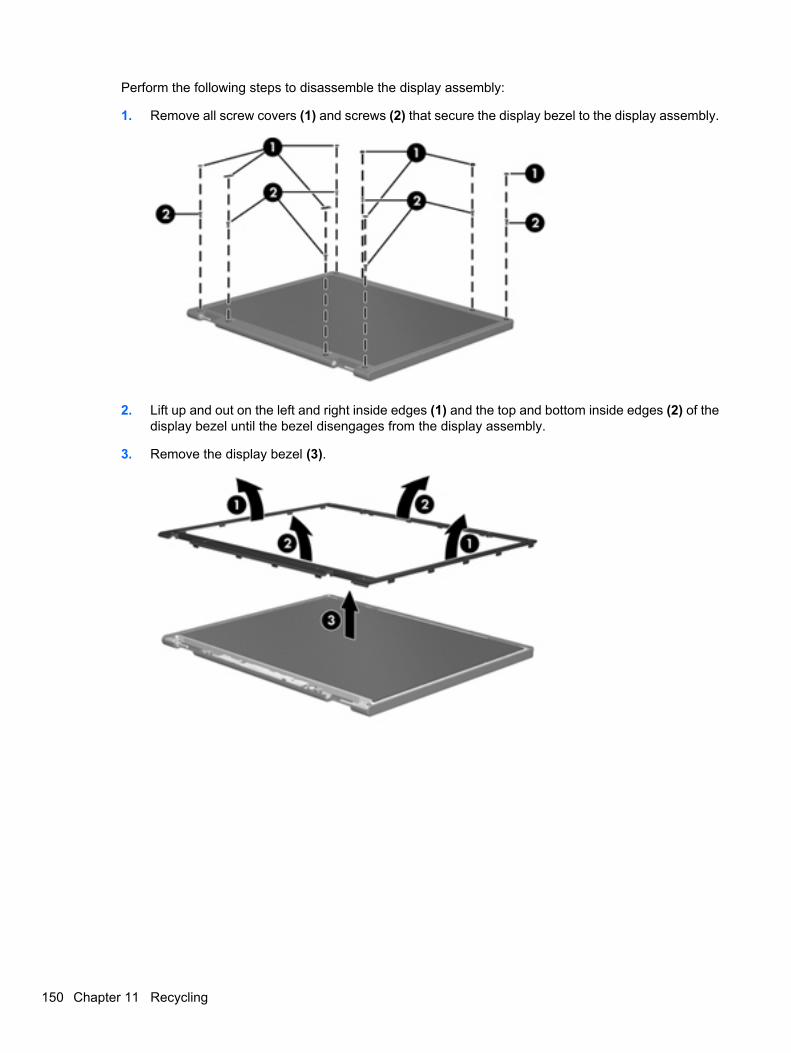
Perform the following steps to disassemble the display assembly:
1. Remove all screw covers (1) and screws (2) that secure the display bezel to the display assembly.
2. Lift up and out on the left and right inside edges (1) and the top and bottom inside edges (2) of thedisplay bezel until the bezel disengages from the display assembly.
3. Remove the display bezel (3).
150 Chapter 11 Recycling
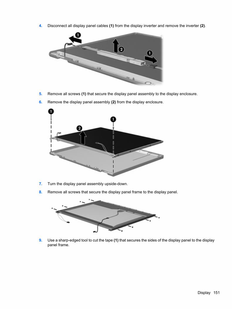
4. Disconnect all display panel cables (1) from the display inverter and remove the inverter (2).
5. Remove all screws (1) that secure the display panel assembly to the display enclosure.
6. Remove the display panel assembly (2) from the display enclosure.
7. Turn the display panel assembly upside-down.
8. Remove all screws that secure the display panel frame to the display panel.
9. Use a sharp-edged tool to cut the tape (1) that secures the sides of the display panel to the displaypanel frame.
Display 151
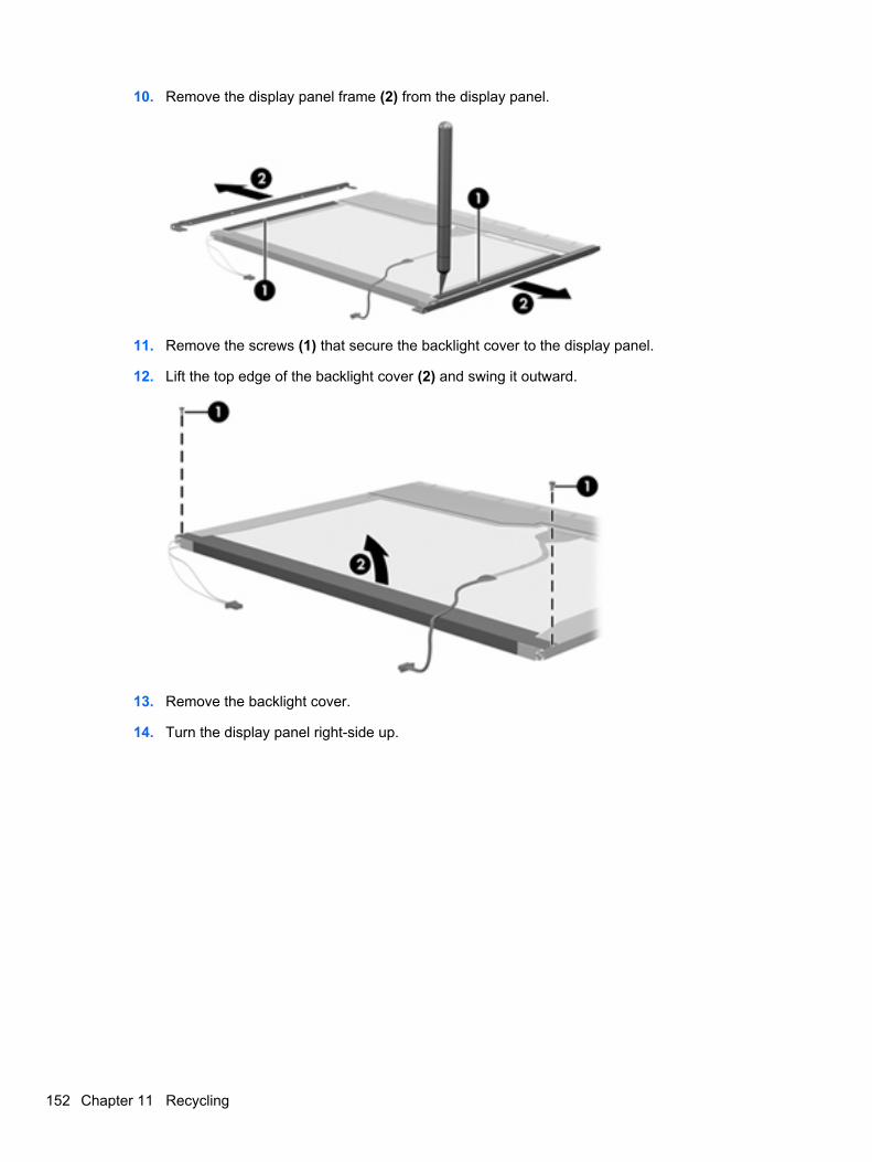
10. Remove the display panel frame (2) from the display panel.
11. Remove the screws (1) that secure the backlight cover to the display panel.
12. Lift the top edge of the backlight cover (2) and swing it outward.
13. Remove the backlight cover.
14. Turn the display panel right-side up.
152 Chapter 11 Recycling
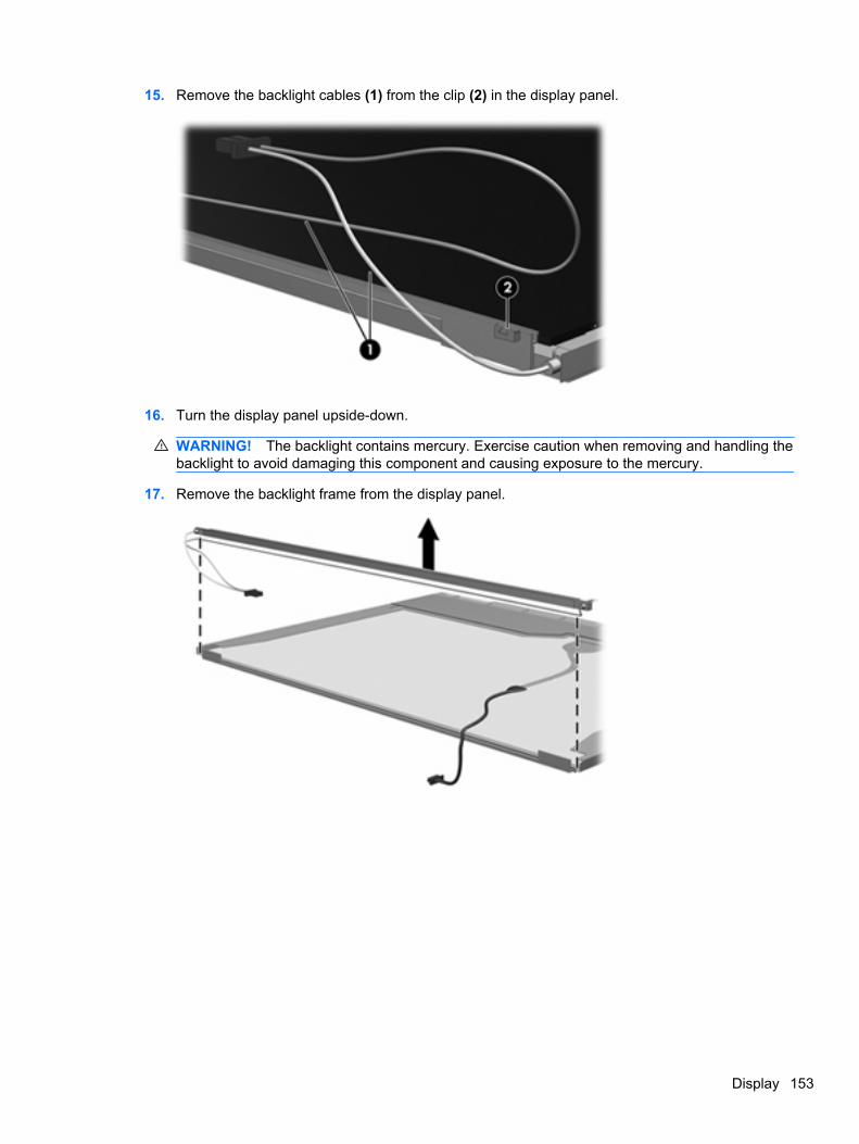
15. Remove the backlight cables (1) from the clip (2) in the display panel.
16. Turn the display panel upside-down.
WARNING! The backlight contains mercury. Exercise caution when removing and handling thebacklight to avoid damaging this component and causing exposure to the mercury.
17. Remove the backlight frame from the display panel.
Display 153
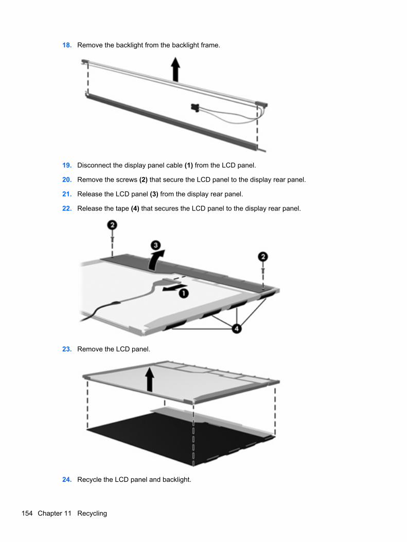
18. Remove the backlight from the backlight frame.
19. Disconnect the display panel cable (1) from the LCD panel.
20. Remove the screws (2) that secure the LCD panel to the display rear panel.
21. Release the LCD panel (3) from the display rear panel.
22. Release the tape (4) that secures the LCD panel to the display rear panel.
23. Remove the LCD panel.
24. Recycle the LCD panel and backlight.
154 Chapter 11 Recycling
Index
Symbols/Numerics1394 port 16
AAC adapter, spare part
numbers 29, 30accessory battery connectort 18AMT options
AMT setup prompt(CTRL-P) 103
firmware progress eventsupporty 103
firmware verbosity 103terminal emulation mode 103TYPE-131 in SMBIOS 103unconfigure AMT on next
boot 103USB key provisioning
support 103antennas, disconnecting 58, 65audio, product description 4audio-in jack
location 17pin assignments 143
audio-out jacklocation 17pin assignments 143
Bbacking up files 136backup
files and folders 140hard drive 141modifications made to
system 141scheduling 142
Backup and Restore Center 136,137
base enclosure, spare partnumber 25, 33
batterylocation 18removal 44spare part number 25, 30,
36, 44battery bay 18battery latch 18battery light 14, 15BIOS Administrator password 98Blu-ray Disc ROM Drive
specifications 110Blu-ray Disc ROM with SuperMulti
DVD±R/RW DL Driveremoval 46spare part number 25, 28,
33, 46Bluetooth module
removal 53spare part number 31spare part numbers 25, 53
Bluetooth module cover,illustrated 27
boot options 101boot order 101bottom components 18built-in device
ambient light sensor 102Bluetooth device radio 102embedded WLAN 102fingerprint reader 102integrated camera 102LAN/WLAN switching 102modem 102Network Interface Controller
(LAN) 102Notebook Multibay 102Wake on LAN 102wireless button 102WWAN device radio 102
built-in device options 102buttons
info 11pointing stick 10, 13power 11presentation 12TouchPad 10volume mute 12wireless 12
CCable Kit
contents 27spare part number 26, 27,
33cables, service considerations 38caps lock light 14carrying case, spare part
number 29chipset, product description 2components
bottom 18buttons 11display 9fingerprint reader 11front 15keys 12left-side 16lights 13pointing devices 10rear 17right-side 17switch 11top 10
computer feetillustrated 27locations 43spare part number 43
Computer Setupaccessing 96
Index 155
Diagnostics menu 100File menu 98navigating and selecting 97restoring factory settings 97Security menu 98System Configuration
menu 101using 97
computer specifications 104connectors
docking 18power 17service considerations 38
creating a backup 136creating recovery points 141
Ddevice configurations 101Diagnostics menu 100Disk Sanitizer 99diskette drive
precautions 38product description 4spare part number 29
display assemblyremoval 48spare part numbers 20, 21,
32, 35, 48display assembly with integrated
webcamspare part numbers 32, 34,
35display bezel
release 48removal 72spare part numbers 21, 34,
35, 72display bezel with integrated
webcam, spare part number 34display component recycling 149display components 9display hinge
removal 72spare part number 21, 33,
34, 73display inverter
removal 48spare part number 22, 48
display panelproduct description 2removal 73
display release latch 15display specifications 105, 106,
107display switch 12docking connector 18docking support, product
description 5drive light 14, 15DriveLock password 99DriveLock, automatic 99drives
boot order 101preventing damage 38
Dual-Core CPU 102DVD-ROM Drive
precautions 38removal 46spare part number 25, 28,
29, 33, 46specifications 111
DVD/CD-RW Combo Driveprecautions 38spare part number 29
DVD±RW and CD-RW SuperMultiDL Combo Drive with LightScribe
removal 46spare part number 25, 28,
33, 46
Eelectrostatic discharge 39eSATA port 16esc key 12Ethernet, product description 4Execution Disable 101ExpressCard assembly
removal 89spare part number 33, 89
ExpressCard slot 16ExpressCard slot insert,
illustrated 27extended life battery, spare part
number 30external media cards, product
description 5
external monitor portlocation 17pin assignments 144
External MultiBay II power cableand stand, spare partnumber 29
External MultiBay II, spare partnumber 29
Ff11 recovery 138fan
removal 79spare part number 23, 79spare part numbers 33
feetillustrated 27locations 43spare part number 43
File menu 98fingerprint reader board, spare part
number 23, 33fn key 12front components 15function keys 13
Ggraphics card
removal 85spare part numbers 23, 33,
34, 85graphics, product description 2grounding equipment and
methods 41
Hhard disk test 100hard drive
location 18precautions 38product description 3removal 50spare part number 34spare part numbers 25, 28,
33, 35, 50specifications 108
hard drive backup 141hard drive bay 18hard drive bracket, removal 52
156 Index

hard drive coverillustrated 26removal 51
hard drive recovery 138, 142HDMI port 16headphone jack
location 17pin assignments 143
heat sinkremoval 81spare part number 23, 81
hingeremoval 72spare part number 21, 33,
34, 73HP Extended Life Battery, spare
part number 29HP Fingerprint Sensor 12HP QuickLook 2 102HP SpareKey enrollment 99HP un2400 Mobile Broadband
Modulespare part number 25, 58
HP un2400 Mobile BroadbandModule, spare part number 31
II/O address specifications 114info button 11interrupt specifications 113inverter
removal 48spare part number 31, 48
Jjacks
audio-in 17audio-out 17headphone 17microphone 17modem 17network 16RJ-11 17RJ-45 16
Kkeyboard
product description 5removal 60spare part numbers 22, 31,
60
keypad keys 13keys
esc 12fn 12function 13keypad 13pointing stick 12Windows applications 13Windows logo 13
LLAN Power Save 101language, changing in Computer
Setup 101LED board
spare part number 22spare part numbers 34
left-side components 16legacy support, USB 96, 101lights
battery 14, 15caps lock 14drive 14, 15num lock 14power 13, 15volume down 14volume mute 14volume up 14wireless 13, 15
Mmass storage devices, spare part
numbers 28Media Card Reader 16memory map specifications 116memory module
product description 3removal 56spare part numbers 25, 33,
56memory module compartment 18memory module compartment
coverillustrated 26removal 54, 56, 58
microphoneillustrated 27product description 4
microphone jacklocation 17pin assignments 143
model name 1modem jack
location 17pin assignments 145
modem moduleproduct description 4removal 63spare part number 24, 30,
63monitor port
location 17pin assignments 144
Nnetwork jack
location 16pin assignments 145
num lock light 14
Ooperating system, product
description 6optical drive
location 17precautions 38product description 3removal 46spare part numbers 25, 28,
46specifications 109, 110, 111
optical drive bracketspart part number 28, 34, 46
Ppacking guidelines 40parallel port mode 101passwords 98pin assignments
audio-in jack 143audio-out jack 143external monitor port 144headphone jack 143microphone jack 143modem jack 145monitor port 144network jack 145RJ-11 145
Index 157
RJ-45 jack 145Universal Serial Bus (USB)
port 146plastic parts 37Plastics Kit
contents 26spare part number 24, 26,
33pointing device
components 10illustrated 10product description 5
pointing device componentspointing stick 10pointing stick buttons 10TouchPad 10TouchPad buttons 10TouchPad scroll zone 10
pointing stick 10, 12pointing stick buttons 10, 13pointing stick, spare part
number 31port options
1394 port 103ExpressCard slot 103flash media reader 103parallel port 103serial port 103Smart Card slot 103USB port 103
ports1394 16eSATA 16external monitor 17HDMI 16monitor 17product description 5Universal Serial Bus
(USB) 16, 17power button 11power connector 17power cord
set requirements 147spare part numbers 29, 31
power light 13, 15power requirements, product
description 6presentation button 12processor
product description 1
removal 84spare part numbers 24, 35,
84product description
audio 4chipset 2diskette drive 4display panel 2docking support 5Ethernet 4external media cards 5graphics 2hard drives 3keyboard 5memory module 3microphone 4modem module 4operating system 6optical drives 3pointing devices 5ports 5power requirements 6processors 1product name 1security 6serviceability 8webcam 4wireless 4
product name 1
RRAID (Redundant Array of
Independent Disks)devices 101
rear components 17recovering information 137recovery partition 138recovery points 141removal/replacement
preliminaries 37procedures 42
restore security defaults 103restore the factory settings 98restoring the hard drive 138right-side components 17RJ-11 connector cable
illustrated 27removal 91
RJ-11 jacklocation 17pin assignments 145
RJ-45 jacklocation 16pin assignments 145
RTC batteryremoval 54spare part number 25, 34,
54Rubber Kit
spare part numbers 33run-in test 100
SSATA (Serial Advanced
Technology Attachment) devicesAHCI (Advanced Host Controller
Interface) 101IDE (Integrated Drive
Electronics) 101scheduling backups 142Screw Kit
contents 117spare part number 30, 33
screw listing 117Secondary Battery Fast
Charge 102security cable slot 17Security menu
allow reset of HP ProtectToolssecurity keys 99
always prompt for HP SpareKeyenrollment 99
Automatic DriveLock 99change password 99Disk Sanitizer 99DriveLock 99fingerprint reader reset 99HP Sparekey 99HP Sparekey enrollment 99password policy 99set up BIOS Administrator
password 98System IDs 99user management 99
security, product description 6service considerations 37service tag 19, 42
158 Index
serviceability, productdescription 8
set security level 103setup utility
Diagnostics menu 100File menu 98navigating and selecting 97restoring factory settings 97Security menu 98System Configuration
menu 101SIM
removal 45spare part number 24
smart card reader 16solid-state drive, spare part
numbers 26, 28, 34, 36, 50speaker assembly
removal 87spare part number 25, 33,
87speakers 15specifications
Blu-ray Disc ROM Drive 110computer 104display 105, 106, 107DVD-ROM Drive 111DVD±RW and CD-RW
SuperMulti DL ComboDrive 109
hard drive 108I/O addresses 114interrupts 113memory map 116optical drive 109, 110, 111system DMA 112
start-up test 100static-shielding materials 41switch cover
removal 65spare part number 22, 33,
65system backup 141system board
removal 88spare part number 24spare part numbers 33, 34,
88System Configuration menu 101system date and time 98
System Diagnostics menu 100system DMA 112system fan 101system IDs 99system information 98system memory map 116system recovery points 141
TThermal Material Kit, spare part
numbers 23, 33, 34, 81, 85thermal material, replacement 82tools required 37top components 10top cover
removal 74spare part number 23, 74spare part numbers 33, 34
TouchPadremoval 77spare part numbers 23, 34,
77TouchPad buttons 10TouchPad scroll zone 10transporting guidelines 40TXT (Intel® Trusted Execution
Technology) 102
UUnified Extensible Firmware
Interface (UEFI) mode 102Universal Serial Bus (USB) port
location 16, 17pin assignments 146
USB legacy support 96, 101USB/audio board
removal 94spare part number 25, 94spare part numbers 33
USB/audio cable, illustrated 27
Vvents 16, 18Virtualization Technology 102volume down light 14volume mute button 12volume mute light 14volume scroll zone 12volume up light 14
Wwebcam, product description 4Windows applications key 13Windows logo key 13Windows Vista operating system
DVD 139Wireless Antenna Kit, spare part
number 33wireless antennas,
disconnecting 58, 65wireless button 12wireless light 13, 15wireless, product description 4WLAN antennas, locations 9WLAN module
removal 64spare part number 30, 31,
34, 64spare part numbers 23
workstation guidelines 40WWAN antennas, locations 9WWAN module
removal 58spare part number 25, 31,
58
Index 159