HP Disk Drive Replacement Instructions.pdf
6
HP Disk Drive Replacement Instructions Abstract These instructions apply to Fibre Channel and SAS disk drives. © Copyright 2012 Hewlett-Packard Development Company, L.P. Printed in Puerto Rico *5697-1679* HP Part Number: 5697-1679 Published: June 2012 Edition: 2 About this document For the latest documentation, go to h t tp:// w w w .hp .co m/su ppo r t/man uals , and select your product. The information contained herein is subject to change without notice. The only warranties for HP products and services are set forth in the express warranty statements accompanying such products and services. Nothing herein should be construed as constituting an additional warranty. HP shall not be liable for technical or editorial errors or omissions contained herein. WARRANTY STATEMENT: To obtain a copy of the warranty for this product, see the warranty information website: h t tp://w w w .hp .co m/go/s t o r age w ar r an t y Before you begin Observe the following precautions when replacing the disk drive: • Ensure you have a replacement part available before removing the failed component. Removing a component impacts cooling within the enclosure. Use a drive blank if a new drive is not available. • HP recommends that the replacement drive matches the capacity and speed of the original drive. For example, if the original drive was a 300 GB, 15K RPM drive, the replacement would be a 300 GB, 15K RPM drive. • P63x0 and P65x0 storage systems support SAS disk drives with EVA on the front identification label. Other SAS drives are not supported. • Do not remove more than one disk drive at a time from the enclosure. Doing so would impact cooling of the enclosure and can cause data loss. • Parts can be damaged by electrostatic discharge. Use proper antistatic protection. • Have a copy of the product user guide available for reference. You can download a copy of the user guide from the product support page on the HP website. Figure 1 (page 2) shows the numbering of Fibre Channel disk drives in the disk enclosure used with the EVA. Page 1
Transcript of HP Disk Drive Replacement Instructions.pdf

HP Disk Drive ReplacementInstructions
AbstractThese instructions apply to Fibre Channel and SAS diskdrives.
© Copyright 2012 Hewlett-Packard Development Company, L.P.Printed in Puerto Rico
*5697-1679*HP Part Number: 5697-1679Published: June 2012Edition: 2
About this documentFor the latest documentation, go to http://www.hp.com/support/manuals, and select yourproduct.The information contained herein is subject to changewithout notice. The only warranties for HP productsand services are set forth in the express warrantystatements accompanying such products and services.Nothing herein should be construed as constituting anadditional warranty. HP shall not be liable for technicalor editorial errors or omissions contained herein.WARRANTY STATEMENT: To obtain a copy of thewarranty for this product, see the warranty informationwebsite:http://www.hp.com/go/storagewarranty
Before you beginObserve the following precautions when replacing thedisk drive:• Ensure you have a replacement part available
before removing the failed component. Removinga component impacts cooling within the enclosure.Use a drive blank if a new drive is not available.
• HP recommends that the replacement drivematches the capacity and speed of the originaldrive. For example, if the original drive was a300 GB, 15K RPM drive, the replacement wouldbe a 300 GB, 15K RPM drive.
• P63x0 and P65x0 storage systems support SASdisk drives with EVA on the front identificationlabel. Other SAS drives are not supported.
• Do not remove more than one disk drive at a timefrom the enclosure. Doing so would impactcooling of the enclosure and can cause data loss.
• Parts can be damaged by electrostatic discharge.Use proper antistatic protection.
• Have a copy of the product user guide availablefor reference. You can download a copy of theuser guide from the product support page on theHP website.
Figure 1 (page 2) shows the numbering of FibreChannel disk drives in the disk enclosure used withthe EVA.
Page 1

Figure 1 FC disk drive numbering
Figure 2 (page 2) shows the numbering of SAS smallform factor (SFF) disk drives and Figure 3 (page 2)shows the numbering of large form factor (LFF) diskdrives in the disk enclosure used with theP63x0/P65x0 EVA.
Figure 2 SAS SFF disk drive numbering
Figure 3 SAS LFF disk drive numbering
Types of disk drive failuresThere are two types of disk drive failures:• Hard failure: The disk drive is no longer
functioning properly and has been assigned afailed status. This type of failure is indicated byan operational state of (Failed) in HP P6000Command View. The amber fault status indicatoron the disk is typically on.
• Impending failure: Although the disk drive is stillfunctioning, errors have been detected thatindicate an impending failure. This type of failureis not accompanied by a failed status.
CAUTION: A disk drive with animpending failure appears to be operatingnormally in HP P6000 Command View,and the fault light on the disk is off.Therefore, it is important that you positivelyidentify the disk drive before performingthe replacement. Work with the HP SolutionCenter to ensure you identify the correctdisk drive for replacement.
Verifying system redundancyBefore replacing a disk, examine the redundancy statusof the entire storage system to ensure a disk can beremoved without impacting data availability.1. Open HP P6000 Command View and click the
icon of the storage system you want to view(Figure 4 (page 2)).
Figure 4 Selecting a storage system
2. On the Initialized Storage System Propertieswindow, click Check Redundancy (Figure 5 (page2)).
Figure 5 Checking redundancy
3. If the system is redundant, continue with “Verifyingcomponent failure” (page 3).If the system is not redundant, information isdisplayed indicating the cause of the lack ofredundancy. See the HP P6000 Command Viewonline help to interpret the information that isdisplayed. In this situation, work with your HP callcenter agent to determine how to proceed.
CAUTION: Do not proceed with the disk drivereplacement until you are certain the storagesystem is redundant.
Page 2

Verifying component failureBefore replacing a disk drive, use the followingmethods to verify component failure:
CAUTION: If HP P6000 Command View doesnot present a status consistent with the disk statusindicators, or if HP P6000 Command View oryour system monitoring tool indicates multiplehardware failures, contact HP support forassistance (http://www.hp.com/support).
• Analyze all failure messages received. Errormessages identify each disk drive by its rack,enclosure, bay, and UUID (World Wide Name).Record this information to assist you in identifyingthe correct disk before replacing it.The following is a sample of the disk identificationinformation:FRU List: Storage System Name: EVA_1Storage System World Wide ID: 5000-1FE1-0015-42A0
Disk Drive UUID: 2000-0000-871D-FE60
Drive Location --- Enclosure ID: 8 Bay ID: 1 Rack Number: 0
NOTE: The Disk Drive UUID correspondsto the disk Node World Wide Namedisplayed in HP P6000 Command View.
• Observe the disk status indicators (Figure 6 (page3) for Fibre Channel disk drives andFigure 7 (page 3) for SAS disk drives;Table 1 (page 3) describes the LEDs). If a hardfailure has occurred, the amber indicator will beon solid.
Figure 6 FC disk drive status indicators
2. Status1. Locate/Fault
Figure 7 SAS disk drive status indicators
2. Status1. Locate/Fault
Table 1 Disk drive status indicator LED descriptions
DescriptionLED statusLED colorLED
Locate driveSlowblinking (0.5Hz)
Blue1.Locate/Fault
Drive faultSolidAmber
Drive isspinning up
Blinking (1Hz)
Green2. Status
or down andis not ready
Drive activityFast blinking(4 Hz)
Ready foractivity
Solid
• Verify the disk status using HP P6000 CommandView:1. In the Navigation pane, select Storage
system→Hardware→Disk enclosure→Bay.Use the information from the error messageto guide you to the correct disk.
2. In the Content pane, select the Disk Drivetab.
3. Compare the disk Node World Wide Namewith the error message UUID informationrecorded earlier to ensure you have selectedthe correct disk (Figure 8 (page 3)).
Figure 8 Identifying NodeWorld Wide Name
Page 3

4. Verify the disk operational state. If a hardfailure has occurred, the operational stateappears as (Failed). A disk with animpending failure indicates Good status untilthe condition of the disk drive degradesenough to become a hard failure.
5. Verify that the Requested usage and Actualusage boxes display Ungrouped(Figure 9 (page 4)).
Figure 9 Verifying disk group status
CAUTION: Both fields must displayUngrouped before you remove thedisk drive.
If both fields display Ungrouped, proceedto Step 7.Otherwise, continue with Step 6.
6. For an impending failure, you must ungroupthe disk before you remove it:Only ungroup one disk at a time. Before youungroup a disk, verify that leveling is not inprogress and that sufficient free space isavailable. After you ungroup the disk, verifythe status of the disk group before continuing.For more information about leveling and freespace, see the Enterprise Virtual Arrayconfiguration best practices white paper foryour array model.a. Click Ungroup.b. Click Ungroup in background.
A dialog box indicates that theOperation succeeded. This indicates thatthe ungroup operation has beeninitiated. You can monitor the progressof the ungroup on the Disk DriveProperties window.
c. Click the Disk Drive tab and monitor theungroup progress in the Migrationprogress box (Figure 10 (page 4)).
Figure 10 Monitoring ungroup progress
When the ungroup is complete, continuewith Step 7.
The ungrouping process can take up toseveral hours to complete. The durationdepends on the capacity of the disk and thelevel of storage system activity.If, after attempting to ungroup the disk, theRequested usage and Actual usage boxes donot display Ungrouped or the Migrationprogress box does not display 100%, contactyour HP-authorized service representative forassistance.
7. Click Remove to prepare the disk forremoval. The status indicators on the disk willflash to help you locate the disk. You cannow proceed to “Removing a disk drive”(page 5).
Page 4
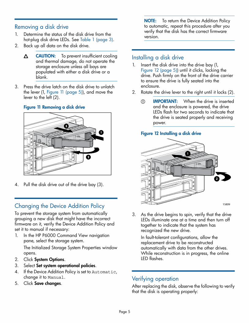
Removing a disk drive1. Determine the status of the disk drive from the
hot-plug disk drive LEDs. See Table 1 (page 3).2. Back up all data on the disk drive.
CAUTION: To prevent insufficient coolingand thermal damage, do not operate thestorage enclosure unless all bays arepopulated with either a disk drive or ablank.
3. Press the drive latch on the disk drive to unlatchthe lever (1, Figure 11 (page 5)), and move thelever to the left (2).
Figure 11 Removing a disk drive
4. Pull the disk drive out of the drive bay (3).
Changing the Device Addition PolicyTo prevent the storage system from automaticallygrouping a new disk that might have the incorrectfirmware on it, verify the Device Addition Policy andset it to manual if necessary:1. In the HP P6000 Command View navigation
pane, select the storage system.The Initialized Storage System Properties windowopens.
2. Click System Options.3. Select Set system operational policies.4. If the Device Addition Policy is set to Automatic,
change it to Manual.5. Click Save changes.
NOTE: To return the Device Addition Policyto automatic, repeat this procedure after youverify that the disk has the correct firmwareversion.
Installing a disk drive1. Insert the disk drive into the drive bay (1,
Figure 12 (page 5)) until it clicks, locking thedrive. Push firmly on the front of the drive carrierto ensure the drive is fully seated into theenclosure.
2. Rotate the drive lever to the right until it locks (2).
IMPORTANT: When the drive is insertedand the enclosure is powered, the driveLEDs flash for two seconds to indicate thatthe drive is seated properly and receivingpower.
Figure 12 Installing a disk drive
3. As the drive begins to spin, verify that the driveLEDs illuminate one at a time and then turn offtogether to indicate that the system hasrecognized the new drive.In fault-tolerant configurations, allow thereplacement drive to be reconstructedautomatically with data from the other drives.While reconstruction is in progress, the onlineLED flashes.
Verifying operationAfter replacing the disk, observe the following to verifythat the disk is operating properly:
Page 5

NOTE: It can take up to 10 minutes for thecomponent to display good status.
• Observe the disk status indicators (Table 1 (page3)). The green indicator should be on or flashing.
• Verify the following using HP P6000 CommandView:
◦ Navigate back to the component and verifythe operational state. It should be (Good).
◦ Ensure that the disk drive is running the correctfirmware. Record the Model number and theFirmware version of the disk (Figure 13 (page6)). Compare the firmware version with thesupported disk drive firmware in the HP P6000Enterprise Virtual Array Disk Drive FirmwareSupport document, which is available at thefollowing website:http://www.hp.com/support/manualsClick Disk Storage Systems under Storage,and then select your product underP6000/EVA Disk Arrays.If the disk is running an unsupported versionof firmware, download the firmware from thefollowing website and install it using theinstructions included with the firmware file. Donot add the disk to a disk group if it is runningan unsupported firmware version.http://www.hp.com/support/evadiskfirmware
NOTE: When downloading thefirmware, use the disk drive modelnumber to locate the correct firmwarefile. If you have difficulty locating thefirmware, contact your HP-authorizedservice representative for assistance.
Figure 13 Verifying model number and firmwareversion
Adding the disk to a disk groupAfter replacing the disk drive, add the disk to a diskgroup. The disk is typically added back into its originaldisk group.1. In the navigation pane, select Storage
system→Hardware→Disk Enclosure→Bay.2. In the content pane, select the Disk Drive tab.3. Click Group to initiate the process for adding the
disk to a disk group.Operation Successful is displayedindicating the disk is now grouped and levelinghas been initiated. The storage system beginsimmediately using the disk.
NOTE: If the Device Addition Policy is set toautomatic, the disk is automatically added to adisk group. In this case, the Group option willnot be available.
Returning the failed componentFollow the return instructions provided with the newcomponent.
Documentation feedbackHP is committed to providing documentation that meetsyour needs. To help us improve the documentation,send any errors, suggestions, or comments toDocumentation Feedback ([email protected]).Include the document title and part number, versionnumber, or the URL when submitting your feedback.
Page 6