HP Compaq 8000f Elite Business PC Ultra-slim Desktopcontent.etilize.com/User-Manual/1016784798.pdfHP...
166
Maintenance and Service Guide HP Compaq 8000f Elite Business PC Ultra-slim Desktop
-
Upload
truonglien -
Category
Documents
-
view
221 -
download
2
Transcript of HP Compaq 8000f Elite Business PC Ultra-slim Desktopcontent.etilize.com/User-Manual/1016784798.pdfHP...

Maintenance and Service Guide
HP Compaq 8000f Elite Business PCUltra-slim Desktop

© Copyright 2010 Hewlett-PackardDevelopment Company, L.P. Theinformation contained herein is subject tochange without notice.
Microsoft and Windows are trademarks ofMicrosoft Corporation in the U.S. and othercountries.
The only warranties for HP products andservices are set forth in the expresswarranty statements accompanying suchproducts and services. Nothing hereinshould be construed as constituting anadditional warranty. HP shall not be liablefor technical or editorial errors or omissionscontained herein.
This document contains proprietaryinformation that is protected by copyright.No part of this document may bephotocopied, reproduced, or translated toanother language without the prior writtenconsent of Hewlett-Packard Company.
HP Compaq 8000f Elite Business PC
Ultra-slim Desktop
First Edition (February 2010)
Document Part Number: 605648-001

About This BookWARNING! Text set off in this manner indicates that failure to follow directions could result in bodilyharm or loss of life.
CAUTION: Text set off in this manner indicates that failure to follow directions could result indamage to equipment or loss of information.
NOTE: Text set off in this manner provides important supplemental information.
iii

iv About This Book

Table of contents
1 Product Features ............................................................................................................................................ 1Front Panel Components ..................................................................................................................... 1Rear Panel Components ...................................................................................................................... 2
2 Installing and Customizing the Software ...................................................................................................... 3Installing the Windows Operating System ............................................................................................ 3Downloading Microsoft Windows Updates ........................................................................................... 3Installing or Upgrading Device Drivers (Windows systems) ................................................................. 4Customizing the Monitor Display (Windows systems) .......................................................................... 4Launching Windows XP from Windows 7 ............................................................................................. 4Accessing Disk Image (ISO) Files ........................................................................................................ 4
3 Computer Setup (F10) Utility ......................................................................................................................... 6Computer Setup (F10) Utilities ............................................................................................................. 6
Using Computer Setup (F10) Utilities .................................................................................. 7Computer Setup—File ......................................................................................................... 8Computer Setup—Storage .................................................................................................. 9Computer Setup—Security ................................................................................................ 10Computer Setup—Power ................................................................................................... 15Computer Setup—Advanced ............................................................................................. 16
Recovering the Configuration Settings ............................................................................................... 19
4 Serial ATA (SATA) Drive Guidelines and Features .................................................................................... 20SATA Hard Drives .............................................................................................................................. 20SATA Hard Drive Cables .................................................................................................................... 20
SATA Data Cable .............................................................................................................. 20SMART ATA Drives ............................................................................................................................ 21Hard Drive Capacities ........................................................................................................................ 21
5 Identifying the Chassis, Routine Care, and Disassembly Preparation .................................................... 22Chassis Designations ......................................................................................................................... 22
Ultra-Slim Desktop (USDT) ................................................................................................ 22Electrostatic Discharge Information .................................................................................................... 23
v

Generating Static ............................................................................................................... 23Preventing Electrostatic Damage to Equipment ................................................................ 23Personal Grounding Methods and Equipment ................................................................... 24Grounding the Work Area .................................................................................................. 24Recommended Materials and Equipment .......................................................................... 24
Operating Guidelines .......................................................................................................................... 25Routine Care ...................................................................................................................................... 26
General Cleaning Safety Precautions ................................................................................ 26Cleaning the Computer Case ............................................................................................ 26Cleaning the Keyboard ...................................................................................................... 26Cleaning the Monitor .......................................................................................................... 27Cleaning the Mouse ........................................................................................................... 27
Service Considerations ...................................................................................................................... 27Power Supply Fan ............................................................................................................. 27Tools and Software Requirements .................................................................................... 28Screws ............................................................................................................................... 28Cables and Connectors ..................................................................................................... 28Hard Drives ........................................................................................................................ 28Lithium Coin Cell Battery ................................................................................................... 29
6 Removal and Replacement Procedures ..................................................................................................... 30Preparation for Disassembly .............................................................................................................. 30Serial Number Location ...................................................................................................................... 31Security Lock Provisions .................................................................................................................... 32
Installing a Security Lock ................................................................................................... 32HP/Kensington MicroSaver Security Cable Lock .............................................. 32Padlock ............................................................................................................. 33HP Business PC Security Lock ......................................................................... 33Front Bezel Security .......................................................................................... 36
Computer Access Panel ..................................................................................................................... 38Front Bezel ......................................................................................................................................... 39Bezel Blank ........................................................................................................................................ 40Installing Additional Memory .............................................................................................................. 41
SODIMMs .......................................................................................................................... 41DDR3-SDRAM SODIMMs ................................................................................................. 41Populating SODIMM Sockets ............................................................................................ 42Installing SODIMMs ........................................................................................................... 43
Cable Management ............................................................................................................................ 45Replacing the Optical Drive ................................................................................................................ 46
Removing the Existing Optical Drive ................................................................................. 46Preparing the New Optical Drive ....................................................................................... 47Installing the New Optical Drive ......................................................................................... 48
Hard Drive .......................................................................................................................................... 49
vi

Hard Drive Cage ................................................................................................................................. 53Port Cover .......................................................................................................................................... 54Front Fan ............................................................................................................................................ 55Card Reader ....................................................................................................................................... 56Speaker .............................................................................................................................................. 57Heat sink ............................................................................................................................................ 58Processor ........................................................................................................................................... 59System Board ..................................................................................................................................... 61Rear Fan ............................................................................................................................................ 62Battery ................................................................................................................................................ 63Changing from Desktop to Tower Configuration ................................................................................ 65Power Supply, External ...................................................................................................................... 66
Appendix A Connector Pin Assignments ...................................................................................................... 67Keyboard ............................................................................................................................................ 67Mouse ................................................................................................................................................. 67Ethernet BNC ..................................................................................................................................... 67Ethernet RJ-45 ................................................................................................................................... 68Serial Interface, Powered and Non-Powered ..................................................................................... 68USB .................................................................................................................................................... 68Microphone ......................................................................................................................................... 69Headphone ......................................................................................................................................... 69Line-in Audio ...................................................................................................................................... 69Line-out Audio .................................................................................................................................... 69Monitor ............................................................................................................................................... 70DisplayPort ......................................................................................................................................... 704-Pin Power (for CPU) ........................................................................................................................ 716-Pin Power (for CPU) (CMT, SFF) .................................................................................................... 71SATA Data and Power ....................................................................................................................... 71PCI Express ....................................................................................................................................... 72PCI Express ....................................................................................................................................... 73
Appendix B Power Cord Set Requirements .................................................................................................. 74General Requirements ....................................................................................................................... 74Japanese Power Cord Requirements ................................................................................................ 74Country-Specific Requirements .......................................................................................................... 75
Appendix C Backup and Recovery ................................................................................................................ 76Windows 7 – Backup and Recovery ................................................................................................... 76
Backing up your information .............................................................................................. 76Performing a recovery ....................................................................................................... 77
Using the Windows recovery tools .................................................................... 78Using F11 .......................................................................................................... 78
vii

Using a Windows 7 operating system DVD (purchased separately) ................. 79Windows Vista – Backup and Recovery ............................................................................................. 80
Backing up your information .............................................................................................. 80Performing a recovery ....................................................................................................... 81
Using the Windows recovery tools .................................................................... 81Using F11 .......................................................................................................... 82Using a Windows Vista operating system DVD (purchased separately) ........... 82
Appendix D Computer Diagnostic Features .................................................................................................. 84Hewlett-Packard Vision Diagnostics ................................................................................................... 84
Accessing HP Vision Diagnostics ...................................................................................... 84Survey Tab ........................................................................................................................ 85Test Tab ............................................................................................................................. 85Status Tab ......................................................................................................................... 86History Tab ........................................................................................................................ 87Errors Tab .......................................................................................................................... 87Help Tab ............................................................................................................................ 87Saving and Printing Information in HP Vision Diagnostics ................................................ 88Downloading the Latest Version of HP Vision Diagnostics ................................................ 88
Protecting the Software ...................................................................................................................... 89
Appendix E Troubleshooting Without Diagnostics ...................................................................................... 90Safety and Comfort ............................................................................................................................ 90Before You Call for Technical Support ............................................................................................... 90Helpful Hints ....................................................................................................................................... 91Solving General Problems .................................................................................................................. 93Solving Power Problems .................................................................................................................... 97Solving Diskette Problems ................................................................................................................. 98Solving Hard Drive Problems ........................................................................................................... 101Solving Media Card Reader Problems ............................................................................................. 104Solving Display Problems ................................................................................................................. 106Solving Audio Problems ................................................................................................................... 110Solving Printer Problems .................................................................................................................. 113Solving Keyboard and Mouse Problems .......................................................................................... 114Solving Hardware Installation Problems ........................................................................................... 116Solving Network Problems ............................................................................................................... 118Solving Memory Problems ............................................................................................................... 122Solving Processor Problems ............................................................................................................ 124Solving CD-ROM and DVD Problems .............................................................................................. 125Solving USB Flash Drive Problems .................................................................................................. 128Solving Front Panel Component Problems ...................................................................................... 129Solving Internet Access Problems .................................................................................................... 130Solving Software Problems .............................................................................................................. 133
viii

Contacting Customer Support .......................................................................................................... 134
Appendix F POST Error Messages ............................................................................................................... 135POST Numeric Codes and Text Messages ..................................................................................... 136Interpreting POST Diagnostic Front Panel LEDs and Audible Codes .............................................. 143
Appendix G Password Security and Resetting CMOS ............................................................................... 146Resetting the Password Jumper ...................................................................................................... 147Clearing and Resetting the CMOS ................................................................................................... 148
Appendix H Drive Protection System (DPS) ................................................................................................ 150Accessing DPS Through Computer Setup ....................................................................................... 151
Appendix I Specifications ............................................................................................................................. 152
Index ................................................................................................................................................................. 154
ix

x

1 Product Features
Front Panel ComponentsDrive configuration may vary by model.
Figure 1-1 Front Panel Components
Table 1-1 Front Panel Components
1 Optical Drive 5 Microphone/Headphone Connector
2 System Power LED 6 USB (Universal Serial Bus) Ports
3 SD Media Card Reader (optional) 7 Hard Drive Activity Light
4 Headphone Connector 8 Dual-State Power Button
NOTE: When a device is plugged into the Microphone/Headphone Connector, a dialog box will pop upasking if you want to use the connector for a microphone line Line-In device or a headphone. You canreconfigure the connector at any time by double-clicking the Realtek HD Audio Manager icon in the Windowstaskbar.
NOTE: The Power On Light is normally green when the power is on. If it is flashing red, there is a problemwith the computer and it is displaying a diagnostic code.
Front Panel Components 1

Rear Panel ComponentsFigure 1-2 Rear Panel Components
Table 1-2 Rear Panel Components
1 Line-Out Connector for powered audiodevices (green)
6 Power Cord Connector
2 PS/2 Keyboard Connector (purple) 7 Line-In Audio Connector (blue)
3 Universal Serial Bus (USB) (6) 8 PS/2 Mouse Connector (green)
4 DisplayPort Monitor Connector 9 RJ-45 Network Connector
5 VGA Monitor Connector (blue)
NOTE: Arrangement and number of connectors may vary by model.
When a device is plugged into the blue Line-In Audio Connector, a dialog box will pop up asking if you want to use theconnector for a line-in device or a microphone. You can reconfigure the connector at any time by double-clicking the RealtekHD Audio Manager icon in the Windows taskbar.
2 Chapter 1 Product Features

2 Installing and Customizing theSoftware
If your computer was not shipped with a Microsoft operating system, some portions of thisdocumentation do not apply. Additional information is available in online help after you install theoperating system.
NOTE: If the computer was shipped with Windows Vista or Windows 7 loaded, you will be promptedto register the computer with HP Total Care before installing the operating system. You will see abrief movie followed by an online registration form. Fill out the form, click the Begin button, and followthe instructions on the screen.
CAUTION: Do not add optional hardware or third-party devices to the computer until the operatingsystem is successfully installed. Doing so may cause errors and prevent the operating system frominstalling properly.
NOTE: Be sure there is a 10.2-cm (4-inch) clearance at the back of the unit and above the monitorto permit the required airflow.
Installing the Windows Operating SystemThe first time you turn on the computer, the operating system is installed automatically. This processtakes about 5 to 10 minutes, depending on which operating system is being installed. Carefully readand follow the instructions on the screen to complete the installation.
CAUTION: Once the automatic installation has begun, DO NOT TURN OFF THE COMPUTERUNTIL THE PROCESS IS COMPLETE. Turning off the computer during the installation process maydamage the software that runs the computer or prevent its proper installation.
NOTE: If the computer shipped with more than one operating system language on the hard drive,the installation process could take up to 60 minutes.
If your computer was not shipped with a Microsoft operating system, some portions of thisdocumentation do not apply. Additional information is available in online help after you install theoperating system.
Downloading Microsoft Windows Updates1. To set up your Internet connection, click Start > Internet Explorer and follow the instructions on
the screen.
2. Once an Internet connection has been established, click the Start button.
3. Select the All Programs menu.
Installing the Windows Operating System 3

4. Click on the Windows Update link.
In Windows Vista and Windows 7, the Windows Update screen appears. Click view availableupdates and make sure all critical updates are selected. Click the Install button and follow theinstructions on the screen.
In Windows XP, you will be directed to the Microsoft Windows Update Web site. If you seeone or more pop-up windows that ask you to install a program from http://www.microsoft.com,click Yes to install the program. Follow the instructions on the Microsoft Web site to scan forupdates and install critical updates and service packs.
It is recommended that you install all of the critical updates and service packs.
5. After the updates have been installed, Windows will prompt you to reboot the machine. Be sureto save any files or documents that you may have open before rebooting. Then select Yes toreboot the machine.
Installing or Upgrading Device Drivers (Windowssystems)
When installing optional hardware devices after the operating system installation is complete, youmust also install the drivers for each of the devices.
If prompted for the i386 directory, replace the path specification with C:\i386, or use the Browsebutton in the dialog box to locate the i386 folder. This action points the operating system to theappropriate drivers.
Obtain the latest support software, including support software for the operating system fromhttp://www.hp.com/support. Select your country and language, select Download drivers andsoftware (and firmware), enter the model number of the computer, and press Enter.
Customizing the Monitor Display (Windows systems)If you wish, you can select or change the monitor model, refresh rates, screen resolution, colorsettings, font sizes, and power management settings. To do so, right-click on the Windows Desktop,then click Personalize in Windows Vista and Windows 7 or Properties in Windows XP to changedisplay settings. For more information, refer to the online documentation provided with the graphicscontroller utility or the documentation that came with your monitor.
Launching Windows XP from Windows 7Windows XP Mode for Windows 7 allows you to install and launch Windows XP applications from theWindows 7 taskbar. This feature is available on some computer models only.
To set up from a pre-installed Windows 7 desktop, click Start > Windows Virtual PC > VirtualWindows XP and follow the instructions on the screen.
Accessing Disk Image (ISO) FilesThere are disk image files (ISO files) included on your PC that contain the installation software foradditional software. These CD image files are located in the folder C:\SWSetup\ISOs. Each .iso filecan be burned to CD media to create an installation CD. It is recommended that these disks be
4 Chapter 2 Installing and Customizing the Software

created and the software installed in order to get the most from your PC. The software and image filenames are:
● Corel WinDVD SD and BD – installation software for WinDVD – used to play DVD movies
● HP Insight Diagnostics OR Vision Diagnostics – software to perform diagnostic activities on yourPC
Accessing Disk Image (ISO) Files 5

3 Computer Setup (F10) Utility
Computer Setup (F10) UtilitiesUse Computer Setup (F10) Utility to do the following:
● Change factory default settings.
● Set the system date and time.
● Set, view, change, or verify the system configuration, including settings for processor, graphics,memory, audio, storage, communications, and input devices.
● Modify the boot order of bootable devices such as hard drives, diskette drives, optical drives, orUSB flash media devices.
● Enable Quick Boot, which is faster than Full Boot but does not run all of the diagnostic tests runduring a Full Boot. You can set the system to:
❑ always Quick Boot (default);
❑ periodically Full Boot (from every 1 to 30 days); or
❑ always Full Boot.
● Select Post Messages Enabled or Disabled to change the display status of Power-On Self-Test(POST) messages. Post Messages Disabled suppresses most POST messages, such asmemory count, product name, and other non-error text messages. If a POST error occurs, theerror is displayed regardless of the mode selected. To manually switch to Post MessagesEnabled during POST, press any key (except F1 through F12).
● Establish an Ownership Tag, the text of which is displayed each time the system is turned on orrestarted.
● Enter the Asset Tag or property identification number assigned by the company to this computer.
● Enable the power-on password prompt during system restarts (warm boots) as well as duringpower-on.
● Establish a setup password that controls access to the Computer Setup (F10) Utility and thesettings described in this section.
● Secure integrated I/O functionality, including the serial, USB, or parallel ports, audio, orembedded NIC, so that they cannot be used until they are unsecured.
● Enable or disable removable media boot ability.
● Enable or disable legacy diskette write ability (when supported by hardware).
6 Chapter 3 Computer Setup (F10) Utility

● Solve system configuration errors detected but not automatically fixed during the Power-On Self-Test (POST).
● Replicate the system setup by saving system configuration information on diskette and restoringit on one or more computers.
● Execute self-tests on a specified ATA hard drive (when supported by drive).
● Enable or disable DriveLock security (when supported by drive).
Using Computer Setup (F10) UtilitiesComputer Setup can be accessed only by turning the computer on or restarting the system.To access the Computer Setup Utilities menu, complete the following steps:
1. Turn on or restart the computer. If you are in Microsoft Windows, click Start > Shut Down >Restart.
2. As soon as the computer is turned on, press F10 when the monitor light turns green to enterComputer Setup. Press Enter to bypass the title screen, if necessary.
NOTE: If you do not press F10 at the appropriate time, you must restart the computer andagain press F10 when the monitor light turns green to access the utility.
3. Select your language from the list and press Enter.
4. A choice of five headings appears in the Computer Setup Utilities menu: File, Storage, Security,Power, and Advanced.
5. Use the arrow (left and right) keys to select the appropriate heading. Use the arrow (up anddown) keys to select the option you want, then press Enter. To return to the Computer SetupUtilities menu, press Esc.
6. To apply and save changes, select File > Save Changes and Exit.
● If you have made changes that you do not want applied, select Ignore Changes and Exit.
● To reset to factory settings or previously saved default settings (some models), selectApply Defaults and Exit. This option will restore the original factory system defaults.
CAUTION: Do NOT turn the computer power OFF while the BIOS is saving the Computer Setup(F10) changes because the CMOS could become corrupted. It is safe to turn off the computer onlyafter exiting the F10 Setup screen.
Table 3-1 Computer Setup (F10) Utility
Heading Table
File Computer Setup—File on page 8
Storage Computer Setup—Storage on page 9
Security Computer Setup—Security on page 10
Power Computer Setup—Power on page 15
Advanced Computer Setup—Advanced on page 16
Computer Setup (F10) Utilities 7

Computer Setup—FileNOTE: Support for specific Computer Setup options may vary depending on the hardwareconfiguration.
Table 3-2 Computer Setup—File
Option Description
System Information Lists:
● Product name
● SKU number (some models)
● Processor type/speed/stepping
● Cache size (L1/L2) (dual core processors have this listed twice)
● Installed memory size/speed, number of channels (single or dual) (if applicable)
● Integrated MAC address for embedded, enabled NIC (if applicable)
● System BIOS (includes family name and version)
● Chassis serial number
● Asset tracking number
● ME firmware version
● Management mode
About Displays copyright notice.
Set Time and Date Allows you to set system time and date.
Flash System ROM Allows you to update the system ROM with a BIOS image file located on a USB flash mediadevice or CD-ROM.
Replicated Setup Save to Removable Media
Saves system configuration, including CMOS, to a formatted 1.44-MB diskette, a USB flash mediadevice, or a diskette-like device (a storage device set to emulate a diskette drive).
Restore from Removable Media
Restores system configuration from a diskette, a USB flash media device, or a diskette-likedevice.
Default Setup Save Current Settings as Default
Saves the current system configuration settings as the default.
Restore Factory Settings as Default
Restores the factory system configuration settings as the default.
Apply Defaults andExit
Applies the currently selected default settings and clears any established passwords.
Ignore Changesand Exit
Exits Computer Setup without applying or saving any changes.
Save Changes andExit
Saves changes to system configuration or default settings and exits Computer Setup.
8 Chapter 3 Computer Setup (F10) Utility

Computer Setup—StorageNOTE: Support for specific Computer Setup options may vary depending on the hardwareconfiguration.
Table 3-3 Computer Setup—Storage
Option Description
Device Configuration Lists all installed BIOS-controlled storage devices.
When a device is selected, detailed information and options are displayed. The following optionsmay be presented:
CD-ROM: No emulation options available.
Hard Disk: Size, model, serial number, connector color, SMART, emulation type.
● None (prevents BIOS data accesses and disables it as a boot device)
● Hard Disk (treated as a hard disk)
Translation Mode (ATA disks only)
Lets you select the translation mode to be used for the device. This enables the BIOS to accessdisks partitioned and formatted on other systems and may be necessary for users of olderversions of UNIX (e.g., SCO UNIX version 3.2). Options are Automatic, Bit-Shift, LBA Assisted,User, and Off.
CAUTION: Ordinarily, the translation mode selected automatically by the BIOS should not bechanged. If the selected translation mode is not compatible with the translation mode that wasactive when the disk was partitioned and formatted, the data on the disk will be inaccessible.
Default Values (ATA disks only)
NOTE: This feature appears only when User translation mode is selected.
Allows you to specify the parameters (logical cylinders, heads, and sectors per track) used by theBIOS to translate disk I/O requests (from the operating system or an application) into terms thehard drive can accept. Logical cylinders may not exceed 1024. The number of heads may notexceed 256. The number of sectors per track may not exceed 63. These fields are only visibleand changeable when the drive translation mode is set to User.
SATA Defaults
Translation Mode (ATA disks only)
Lets you select the translation mode to be used for the device. This enables the BIOS to accessdisks partitioned and formatted on other systems and may be necessary for users of olderversions of UNIX (e.g., SCO UNIX version 3.2). Options are Automatic, Bit-Shift, LBA Assisted,User, and Off.
CAUTION: Ordinarily, the translation mode selected automatically by the BIOS should not bechanged. If the selected translation mode is not compatible with the translation mode that wasactive when the disk was partitioned and formatted, the data on the disk will be inaccessible.
Computer Setup (F10) Utilities 9

Storage Options Removable Media Boot
Enables/disables ability to boot the system from removable media.
SATA Emulation
Allows you to choose how the SATA controller and devices are accessed by the operatingsystem. There are three supported options: IDE, RAID, and AHCI.
IDE - This is the most backwards-compatible setting of the three options. Operating systemsusually do not require additional driver support in IDE mode.
AHCI (default option) - Allows operating systems with AHCI device drivers loaded to takeadvantage of more advanced features of the SATA controller.
DPS Self-Test Allows you to execute self-tests on ATA hard drives capable of performing the Drive ProtectionSystem (DPS) self-tests.
NOTE: This selection will only appear when at least one drive capable of performing the DPSself-tests is attached to the system.
Boot Order Allows you to:
● Specify the order in which attached devices (such as a USB flash media device, hard drive,optical drive, or network interface card) are checked for a bootable operating system image.Each device on the list may be individually excluded from or included for consideration as abootable operating system source.
● Specify the order of attached hard drives. The first hard drive in the order will have priority inthe boot sequence and will be recognized as drive C (if any devices are attached).
NOTE: MS-DOS drive lettering assignments may not apply after a non-MS-DOS operatingsystem has started.
Shortcut to Temporarily Override Boot Order
To boot one time from a device other than the default device specified in Boot Order, restart thecomputer and press F9 when the monitor light turns green. After POST is completed, a list ofbootable devices is displayed. Use the arrow keys to select the preferred bootable device andpress Enter. The computer then boots from the selected non-default device for this one time.
Computer Setup—SecurityNOTE: Support for specific Computer Setup options may vary depending on the hardwareconfiguration.
Table 3-4 Computer Setup—Security
Option Description
Setup Password Allows you to set and enable a setup (administrator) password.
NOTE: If the setup password is set, it is required to change Computer Setup options, flash theROM, and make changes to certain plug and play settings under Windows.
See the Desktop Management Guide for more information.
Table 3-3 Computer Setup—Storage (continued)
10 Chapter 3 Computer Setup (F10) Utility

Power-On Password Allows you to set and enable a power-on password. The power-on password prompt appearsafter a power cycle. If the user does not enter the correct power-on password, the unit will notboot.
NOTE: This password does not appear on warm boots , such as Ctrl+Alt+Delete or Restartfrom Windows, unless enabled in Password Options (see below).
See the Desktop Management Guide for more information.
Password Options
(This selection appearsonly if a power-onpassword or setuppassword is set.)
Allows you to enable/disable:
● Lock Legacy Resources (appears if a setup password is set)
● Network Server Mode (appears if a power-on password is set)
● Password Prompt on Warm Boot (Ctrl+Alt+Delete) (appears if a power-on password is set)
● Setup Browse Mode (appears if a setup password is set) (allows viewing, but not changing,the F10 Setup Options without entering setup password)
● Stringent Password (appears if a power-on password is set), which when enabled bypassesthe onboard password jumper to disable the power-on password.
● Password prompt on F9, F11, & F12 (allows access to menus without entering setuppassword)
See the Desktop Management Guide for more information.
Smart Cover (somemodels)
Allows you to:
● Lock/unlock the Cover Lock.
● Set the Cover Removal Sensor to Disable/Notify User/Setup Password.
NOTE: Notify User alerts the user that the sensor has detected that the cover has beenremoved. Setup Password requires that the setup password be entered to boot the computer ifthe sensor detects that the cover has been removed.
This feature is supported on some models only. See the Desktop Management Guide for moreinformation.
Device Security Allows you to set Device Available/Device Hidden for:
● Serial ports
● Parallel port
● System audio
● Network controllers (some models)
● Embedded security device (some models)
● SATA0
● SATA1 (some models)
● SATA2 (some models)
● SATA3 (some models)
● eSATA (some models)
Table 3-4 Computer Setup—Security (continued)
Computer Setup (F10) Utilities 11

USB Security Allows you to set Device Available/Device Hidden for:
● Front USB Ports
◦ USB Port 3
◦ USB Port 4
◦ USB Port 5
◦ USB Port 6
● Rear USB Ports
◦ USB Port 7
◦ USB Port 8
◦ USB Port 9
◦ USB Port 10
◦ USB Port 11
◦ USB Port 12
● Accessory USB Ports
◦ USB Port 1
◦ USB Port 2
Slot Security Allows you to disable any PCI or PCI Express slot
Network Service Boot Enables/disables the computer’s ability to boot from an operating system installed on a networkserver. (Feature available on NIC models only; the network controller must be either a PCIexpansion card or embedded on the system board.)
System IDs Allows you to set:
● Asset tag (18-byte identifier), a property identification number assigned by the company tothe computer.
● Ownership tag (80-byte identifier) displayed during POST.
● Chassis serial number or Universal Unique Identifier (UUID) number. The UUID can only beupdated if the current chassis serial number is invalid. (These ID numbers are normally set inthe factory and are used to uniquely identify the system.)
● Keyboard locale setting (for example, English or German) for System ID entry.
DriveLock Security Allows you to assign or modify a master or user password for hard drives. When this feature isenabled, the user is prompted to provide one of the DriveLock passwords during POST. If neitheris successfully entered, the hard drive will remain inaccessible until one of the passwords issuccessfully provided during a subsequent cold-boot sequence.
NOTE: This selection will only appear when at least one drive that supports the DriveLockfeature is attached to the system.
See the Desktop Management Guide for more information.
Table 3-4 Computer Setup—Security (continued)
12 Chapter 3 Computer Setup (F10) Utility

System Security(some models: theseoptions are hardwaredependent)
Data Execution Prevention (some models) (enable/disable) - Helps prevent operating systemsecurity breaches.
PAVP (Models with Blu-ray drives) (disabled/min/max) - PAVP enables the Protected Audio VideoPath in the Chipset. This may allow viewing of some protected high definition content that wouldotherwise be prohibited from playback. Selecting Max will assign 96 Megabytes of systemmemory exclusively to PAVP.
Virtualization Technology (some models) (enable/disable) - Controls the virtualization features ofthe processor. Changing this setting requires turning the computer off and then back on.
Virtualization Technology Directed I/O (some models) (enable/disable) - Controls virtualizationDMA remapping features of the chipset. Changing this setting requires turning the computer offand then back on.
Trusted Execution Technology (some models) (enable/disable) - Controls the underlyingprocessor and chipset features needed to support a virtual appliance. Changing this settingrequires turning the computer off and then back on. To enable this feature you must enable thefollowing features:
● Embedded Security Device Support
● Virtualization Technology
● Virtualization Technology Directed I/O
Embedded Security Device Support (some models) (enable/disable) - Permits activation anddeactivation of the Embedded Security Device. Changing this setting requires turning thecomputer off and then back on.
NOTE: To configure the Embedded Security Device, a Setup password must be set.
● Reset to Factory Settings (some models) (Do not reset/Reset) - Resetting to factory defaultswill erase all security keys. Changing this setting requires turning the computer off and thenback on.
CAUTION: The embedded security device is a critical component of many securityschemes. Erasing the security keys will prevent access to data protected by the EmbeddedSecurity Device. Choosing Reset to Factory Settings may result in significant data loss.
OS management of Embedded Security Device (some models) (enable/disable) - This optionallows the user to limit operating system control of the Embedded Security Device. Changing thissetting requires turning the computer off and then back on. This option allows the user to limit OScontrol of the Embedded Security Device.
● Reset of Embedded Security Device through OS (some models) (enable/disable) - Thisoption allows the user to limit the operating system ability to request a Reset to FactorySettings of the Embedded Security Device. Changing this setting requires turning thecomputer off and then back on.
NOTE: To enable this option, a Setup password must be set.
Table 3-4 Computer Setup—Security (continued)
Computer Setup (F10) Utilities 13

Master Boot RecordSecurity
Protects the master boot record from viruses or other corruption. Saves of copy of the currentmaster boot record.
Setup Security Level Provides a method to allow end-users limited access to change specified setup options, withouthaving to know the Setup Password.
This feature allows the administrator the flexibility to protect changes to essential setup options,while allowing the user to view system settings and configure nonessential options. Theadministrator specifies access rights to individual setup options on a case-by-case basis via theSetup Security Level menu. By default, all setup options are assigned Setup Password, indicatingthe user must enter the correct Setup Password during POST to make changes to any of theoptions. The administrator may set individual items to None, indicating the user can makechanges to the specified options when setup has been accessed with invalid passwords. Thechoice, None, is replaced by Power-On Password if a Power-On Password is enabled.
NOTE: Setup Browse Mode must be set to Enable in order for the user to enter Setup withoutknowing the setup password.
Table 3-4 Computer Setup—Security (continued)
14 Chapter 3 Computer Setup (F10) Utility
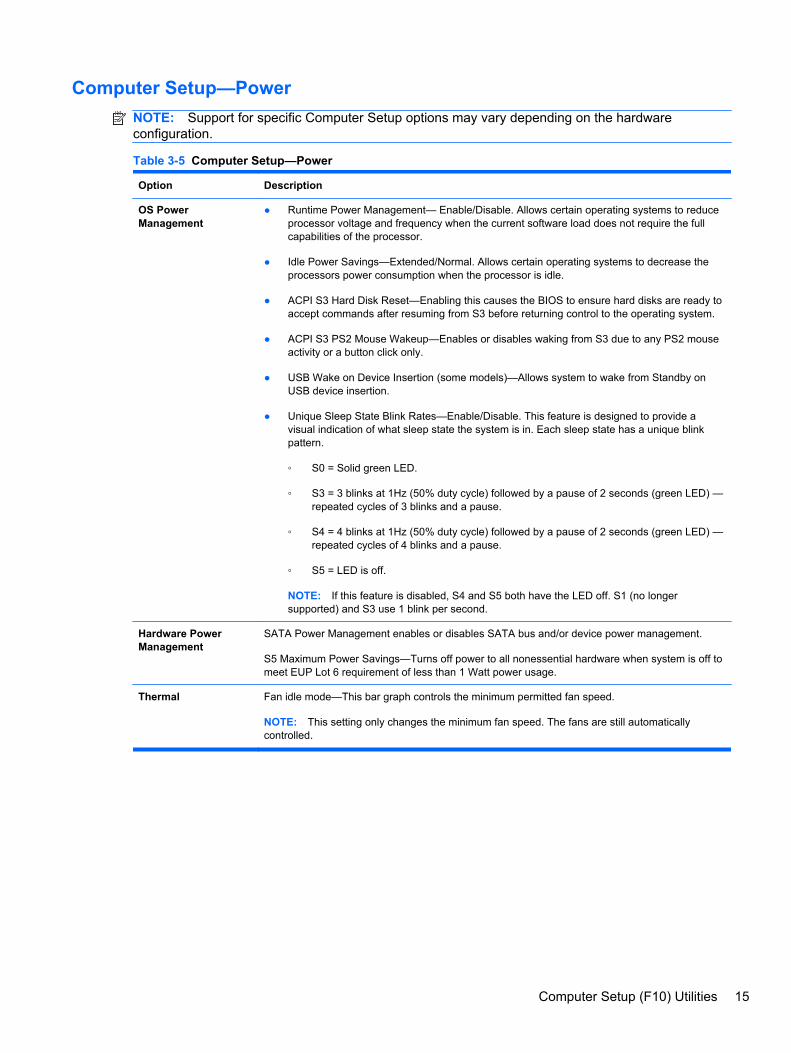
Computer Setup—PowerNOTE: Support for specific Computer Setup options may vary depending on the hardwareconfiguration.
Table 3-5 Computer Setup—Power
Option Description
OS PowerManagement
● Runtime Power Management— Enable/Disable. Allows certain operating systems to reduceprocessor voltage and frequency when the current software load does not require the fullcapabilities of the processor.
● Idle Power Savings—Extended/Normal. Allows certain operating systems to decrease theprocessors power consumption when the processor is idle.
● ACPI S3 Hard Disk Reset—Enabling this causes the BIOS to ensure hard disks are ready toaccept commands after resuming from S3 before returning control to the operating system.
● ACPI S3 PS2 Mouse Wakeup—Enables or disables waking from S3 due to any PS2 mouseactivity or a button click only.
● USB Wake on Device Insertion (some models)—Allows system to wake from Standby onUSB device insertion.
● Unique Sleep State Blink Rates—Enable/Disable. This feature is designed to provide avisual indication of what sleep state the system is in. Each sleep state has a unique blinkpattern.
◦ S0 = Solid green LED.
◦ S3 = 3 blinks at 1Hz (50% duty cycle) followed by a pause of 2 seconds (green LED) —repeated cycles of 3 blinks and a pause.
◦ S4 = 4 blinks at 1Hz (50% duty cycle) followed by a pause of 2 seconds (green LED) —repeated cycles of 4 blinks and a pause.
◦ S5 = LED is off.
NOTE: If this feature is disabled, S4 and S5 both have the LED off. S1 (no longersupported) and S3 use 1 blink per second.
Hardware PowerManagement
SATA Power Management enables or disables SATA bus and/or device power management.
S5 Maximum Power Savings—Turns off power to all nonessential hardware when system is off tomeet EUP Lot 6 requirement of less than 1 Watt power usage.
Thermal Fan idle mode—This bar graph controls the minimum permitted fan speed.
NOTE: This setting only changes the minimum fan speed. The fans are still automaticallycontrolled.
Computer Setup (F10) Utilities 15
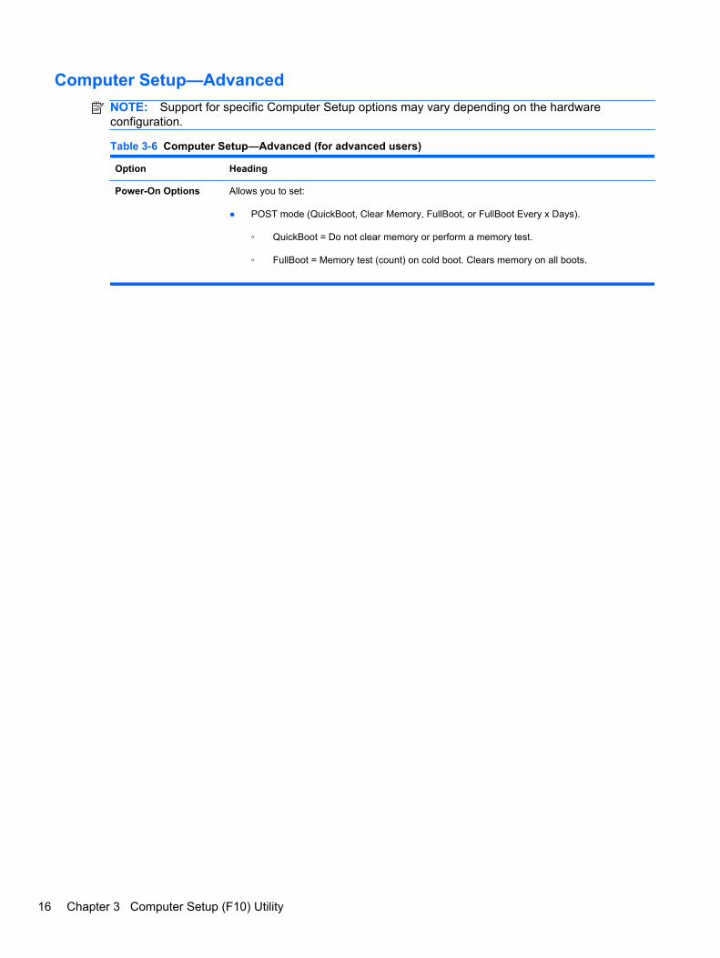
Computer Setup—AdvancedNOTE: Support for specific Computer Setup options may vary depending on the hardwareconfiguration.
Table 3-6 Computer Setup—Advanced (for advanced users)
Option Heading
Power-On Options Allows you to set:
● POST mode (QuickBoot, Clear Memory, FullBoot, or FullBoot Every x Days).
◦ QuickBoot = Do not clear memory or perform a memory test.
◦ FullBoot = Memory test (count) on cold boot. Clears memory on all boots.
16 Chapter 3 Computer Setup (F10) Utility

◦ Clear Memory = No memory count on cold boot. Clears memory on all boots.
◦ FullBoot Every x Days = Memory count on 1st cold boot on or after the xth day. Nomore memory counts until 1st cold boot on or after x days. Clears memory on all boots.
● POST messages (enable/disable).
● F9 prompt (hidden/displayed). Enabling this feature will display the text F9 = Boot Menuduring POST. Disabling this feature prevents the text from being displayed. However,pressing F9 will still access the Shortcut Boot [Order] Menu screen. See Storage > BootOrder for more information.
● F10 prompt (hidden/displayed). Enabling this feature will display the text F10 = Setup duringPOST. Disabling this feature prevents the text from being displayed. However, pressing F10will still access the Setup screen.
● F11 prompt (hidden/displayed). Setting this feature to displayed will display the text F11 =Recovery during POST. Hiding the feature prevents the text from being displayed. However,pressing F11 will still attempt to boot to the HP Backup and Recovery partition. See FactoryRecovery Boot Support for more information.
● F12 prompt (hidden/displayed). Enabling this feature will display the text F12 = Networkduring POST. Disabling this feature prevents the text from being displayed. However,pressing F12 will still force the system to attempt booting from the network.
● Factory Recovery Boot Support (enable/disable). Enabling this feature will cause anadditional prompt, F11 = Recovery, to be displayed during POST on systems withHP Backup and Recovery software installed and configured with a recovery partition on theboot hard drive. Pressing F11 causes the system to boot to the recovery partition and launchHP Backup and Recovery. The F11 = Recovery prompt can be hidden with the F11 prompt(hidden/displayed) option (see above).
● Option ROM Prompt (enable/disable). Enabling this feature will cause the system to displaya message before loading option ROMs. (This feature is supported on some models only.)
● Remote Wakeup Boot Source (remote server/local hard drive).
● After Power Loss (off/on/previous state): Setting this option to:
◦ Off—causes the computer to remain powered off when power is restored.
◦ On—causes the computer to power on automatically as soon as power is restored.
◦ Previous state—causes the computer to power on automatically as soon as power isrestored, if it was on when power was lost.
NOTE: If you turn off power to the computer using the switch on a power strip, you will not beable to use the suspend/sleep feature or the Remote Management features.
● POST Delay (None, 5, 10 15, or 20 seconds). Enabling this feature will add a user-specifieddelay to the POST process. This delay is sometimes needed for hard disks on some PCIcards that spin up very slowly, so slowly that they are not ready to boot by the time POST isfinished. The POST delay also gives you more time to select F10 to enter Computer (F10)Setup.
● Bypass F1 Prompt on Configuration Changes (Enable/Disable). Allows you to set thecomputer not to confirm when changes were made.
Execute Memory Test(some models)
Restarts the computer and executes the POST memory test/logging.
BIOS Power-On Allows you to set the computer to turn on automatically at a time you specify.
Onboard Devices Allows you to set resources for or disable onboard system devices (diskette controller, serial port,or parallel port).
Table 3-6 Computer Setup—Advanced (for advanced users) (continued)
Computer Setup (F10) Utilities 17

PCI Devices ● Lists currently installed PCI devices and their IRQ settings.
● Allows you to reconfigure IRQ settings for these devices or to disable them entirely. Thesesettings have no effect under an ACPI-based operating system.
PCI VGAConfiguration
Displayed only if there are multiple PCI video adapters in the system. Allows you to specify whichVGA controller will be the “boot” or primary VGA controller.
NOTE: In order to see this entry, you must enable Integrated Video (Advanced > DeviceOptions) and Save Changes and Exit.
Bus Options On some models, allows you to enable or disable:
● PCI SERR# Generation.
● PCI VGA Palette Snooping, which sets the VGA palette snooping bit in PCI configurationspace; only needed when more than one graphics controller is installed.
Device Options Allows you to set:
● Printer mode (Bi-Directional, EPP + ECP, Output Only).
● Num Lock State at Power-On (off/on).
● S5 Wake on LAN (enable/disable).
◦ To disable Wake on LAN during the off state (S5), use the arrow (left and right) keys toselect the Advanced > Device Options menu and set the S5 Wake on LAN feature toDisable. This obtains the lowest power consumption available on the computer duringS5. It does not affect the ability of the computer to Wake on LAN from suspend orhibernation, but will prevent it from waking from S5 via the network. It does not affectoperation of the network connection while the computer is on.
◦ If a network connection is not required, completely disable the network controller (NIC)by using the arrow (left and right) keys to select the Security > Device Security menu.Set the Network Controller option to Device Hidden. This prevents the networkcontroller from being used by the operating system and reduces the power used by thecomputer in S5.
● Multi-Processor (enable/disable). This option may be used to disable multi-processor supportunder the OS.
● Internal Speaker (some models) (does not affect external speakers).
● NIC PXE Option ROM Download (enable/disable). The BIOS contains an embedded NICoption ROM to allow the unit to boot through the network to a PXE server. This is typicallyused to download a corporate image to a hard drive. The NIC option ROM takes up memoryspace below 1MB commonly referred to as DOS Compatibility Hole (DCH) space. Thisspace is limited. This F10 option will allow users to disable the downloading of thisembedded NIC option ROM thus giving more DCH space for additional PCI cards which mayneed option ROM space. The default will be to have the NIC option-ROM-enabled.
Table 3-6 Computer Setup—Advanced (for advanced users) (continued)
18 Chapter 3 Computer Setup (F10) Utility

Management Devices The Management Devices menu will only be displayed in the Advanced menu when the BIOSdetects multiple management options.
This option is for installed NIC cards that support ASF or DASH. Use the Management Devicesmenu to select if the BIOS management operations will be through the embedded solution or oneof the installed NIC cards.
ManagementOperations
Allows you to set:
● MEBx Setup Prompt (enable/disable). Enabling this feature displays the CTRL+P promptduring POST. Disabling this feature prevents the prompt from being displayed. However,pressing Ctrl+P still accesses the utility used to configure manageability settings.
The CTRL+P function activates the MEBx Setup menu. If the Setup Password is configured,the user will be prompted to correctly enter it before being allowed to enter the MEBx Setup.It the password is entered incorrectly three times, the MEBx Setup will not be activated.
● Intel Remote PC Assist Prompt (Hidden/Displayed). Displaying this feature displays theCTRL+ALT+F1 prompt during POST. Hiding this feature prevents the prompt from beingdisplayed. However, pressing Ctrl+Alt+F1 still accesses the utility used to attempt to connectto remote help server or services.
● Intel PC Assist Timeout (5, 10, 15, 20, 30, 40, 50, 60, 120, 180, 240 seconds). Allows theuser/administrator is set a time limit for Remote Help to establish contact with a remoteserver when initiated.
● SOL Terminal Emulation Mode. Selects between VT100 and ANSI SOL terminal emulation.SOL terminal emulation mode is only activated during remote AMT redirection operations.The emulation options allow administrators to select which mode works best with theirconsole.
● SOL Local Keyboard (enable/disable). Disable or enable client keyboard during SOLsessions. Some remote remediation may involve having the local client boot a remote imageprovided by an administrator. This option determines if the BIOS will keep the local keyboardenabled or disabled for possible local client interaction. If the local keyboard is disabled, allkeyboard input is only accepted from the remote source.
● Unprovision AMT on next boot. Allows reset of AMT settings.
Recovering the Configuration SettingsThis method of recovery requires that you first perform the Save to Removable Media commandwith the Computer Setup (F10) Utility before Restore is needed. (See Save to Removable Mediaon page 8 in the Computer Setup—File table.)
NOTE: It is recommended that you save any modified computer configuration settings to a diskette,a USB flash media device, or a diskette-like device (a storage device set to emulate a diskette drive)and save the diskette or device for possible future use.
To restore the configuration, insert the diskette, USB flash media device, or other storage mediaemulating a diskette with the saved configuration and perform the Restore from Removable Mediacommand with the Computer Setup (F10) Utility. (See Restore from Removable Media on page 8 inthe Computer Setup—File table.)
Table 3-6 Computer Setup—Advanced (for advanced users) (continued)
Recovering the Configuration Settings 19
4 Serial ATA (SATA) Drive Guidelinesand Features
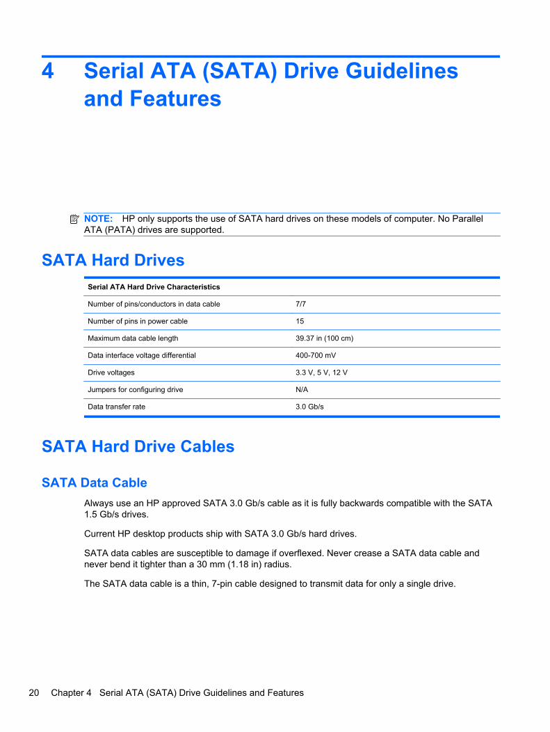
NOTE: HP only supports the use of SATA hard drives on these models of computer. No ParallelATA (PATA) drives are supported.
SATA Hard DrivesSerial ATA Hard Drive Characteristics
Number of pins/conductors in data cable 7/7
Number of pins in power cable 15
Maximum data cable length 39.37 in (100 cm)
Data interface voltage differential 400-700 mV
Drive voltages 3.3 V, 5 V, 12 V
Jumpers for configuring drive N/A
Data transfer rate 3.0 Gb/s
SATA Hard Drive Cables
SATA Data CableAlways use an HP approved SATA 3.0 Gb/s cable as it is fully backwards compatible with the SATA1.5 Gb/s drives.
Current HP desktop products ship with SATA 3.0 Gb/s hard drives.
SATA data cables are susceptible to damage if overflexed. Never crease a SATA data cable andnever bend it tighter than a 30 mm (1.18 in) radius.
The SATA data cable is a thin, 7-pin cable designed to transmit data for only a single drive.
20 Chapter 4 Serial ATA (SATA) Drive Guidelines and Features

SMART ATA DrivesThe Self Monitoring Analysis and Recording Technology (SMART) ATA drives for the HP PersonalComputers have built-in drive failure prediction that warns the user or network administrator of animpending failure or crash of the hard drive. The SMART drive tracks fault prediction and failureindication parameters such as reallocated sector count, spin retry count, and calibration retry count. Ifthe drive determines that a failure is imminent, it generates a fault alert.
Hard Drive CapacitiesThe combination of the file system and the operating system used in the computer determines themaximum usable size of a drive partition. A drive partition is the largest segment of a drive that maybe properly accessed by the operating system. A single hard drive may therefore be subdivided into anumber of unique drive partitions in order to make use of all of its space.
Because of the differences in the way that drive sizes are calculated, the size reported by theoperating system may differ from that marked on the hard drive or listed in the computer specification.Drive size calculations by drive manufacturers are bytes to the base 10 while calculations byMicrosoft are bytes to the base 2.
Drive/Partition Capacity Limits
Maximum Size
File System Controller Type Operating System Partition Drive
FAT 32 ATA Windows XP/Windows Vista/Windows 7 32 GB 2 TB
NTFS ATA Windows XP/Windows Vista/Windows 7 2 TB 2 TB
SMART ATA Drives 21

5 Identifying the Chassis, Routine Care,and Disassembly Preparation
This chapter provides general service information for the computer. Adherence to the procedures andprecautions described in this chapter is essential for proper service.
CAUTION: When the computer is plugged into an AC power source, voltage is always applied tothe system board. You must disconnect the power cord from the power source before opening thecomputer to prevent system board or component damage.
Chassis Designations
Ultra-Slim Desktop (USDT)Figure 5-1 Ultra-Slim Desktop chassis
22 Chapter 5 Identifying the Chassis, Routine Care, and Disassembly Preparation

Electrostatic Discharge InformationA sudden discharge of static electricity from your finger or other conductor can destroy static-sensitivedevices or microcircuitry. Often the spark is neither felt nor heard, but damage occurs. An electronicdevice exposed to electrostatic discharge (ESD) may not appear to be affected at all and can workperfectly throughout a normal cycle. The device may function normally for a while, but it has beendegraded in the internal layers, reducing its life expectancy.
Networks built into many integrated circuits provide some protection, but in many cases, thedischarge contains enough power to alter device parameters or melt silicon junctions.
Generating StaticThe following table shows that:
● Different activities generate different amounts of static electricity.
● Static electricity increases as humidity decreases.
Relative Humidity
Event 55% 40% 10%
Walking across carpet
Walking across vinyl floor
Motions of bench worker
Removing DIPs from plastic tube
7,500 V
3,000 V
400 V
400 V
15,000 V
5,000 V
800 V
700 V
35,000 V
12,000 V
6,000 V
2,000 V
Removing DIPs from vinyl tray
Removing DIPs from Styrofoam
Removing bubble pack from PCB
Packing PCBs in foam-lined box
2,000 V
3,500 V
7,000 V
5,000 V
4,000 V
5,000 V
20,000 V
11,000 V
11,500 V
14,500 V
26,500 V
21,000 V
These are then multi-packaged inside plastic tubes, trays, or Styrofoam.
NOTE: 700 volts can degrade a product.
Preventing Electrostatic Damage to EquipmentMany electronic components are sensitive to ESD. Circuitry design and structure determine thedegree of sensitivity. The following packaging and grounding precautions are necessary to preventdamage to electric components and accessories.
● To avoid hand contact, transport products in static-safe containers such as tubes, bags, orboxes.
● Protect all electrostatic parts and assemblies with conductive or approved containers orpackaging.
● Keep electrostatic sensitive parts in their containers until they arrive at static-free stations.
● Place items on a grounded surface before removing them from their container.
Electrostatic Discharge Information 23
● Always be properly grounded when touching a sensitive component or assembly.
● Avoid contact with pins, leads, or circuitry.
● Place reusable electrostatic-sensitive parts from assemblies in protective packaging orconductive foam.
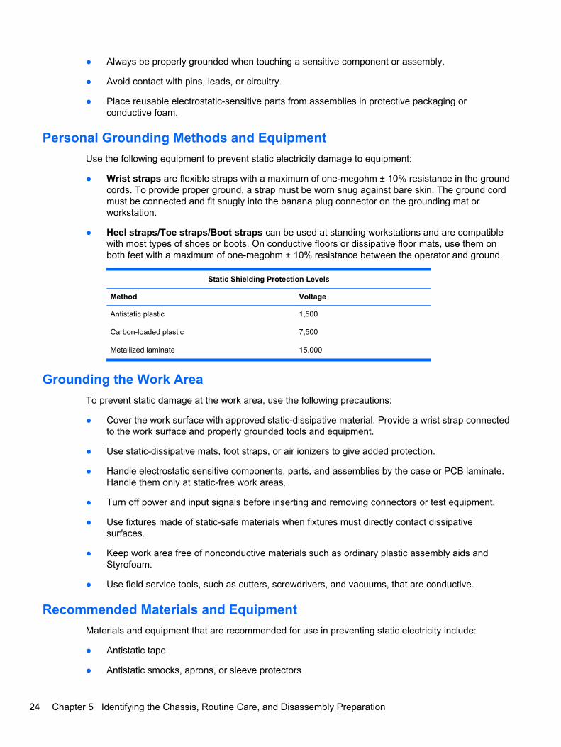
Personal Grounding Methods and EquipmentUse the following equipment to prevent static electricity damage to equipment:
● Wrist straps are flexible straps with a maximum of one-megohm ± 10% resistance in the groundcords. To provide proper ground, a strap must be worn snug against bare skin. The ground cordmust be connected and fit snugly into the banana plug connector on the grounding mat orworkstation.
● Heel straps/Toe straps/Boot straps can be used at standing workstations and are compatiblewith most types of shoes or boots. On conductive floors or dissipative floor mats, use them onboth feet with a maximum of one-megohm ± 10% resistance between the operator and ground.
Static Shielding Protection Levels
Method Voltage
Antistatic plastic
Carbon-loaded plastic
Metallized laminate
1,500
7,500
15,000
Grounding the Work AreaTo prevent static damage at the work area, use the following precautions:
● Cover the work surface with approved static-dissipative material. Provide a wrist strap connectedto the work surface and properly grounded tools and equipment.
● Use static-dissipative mats, foot straps, or air ionizers to give added protection.
● Handle electrostatic sensitive components, parts, and assemblies by the case or PCB laminate.Handle them only at static-free work areas.
● Turn off power and input signals before inserting and removing connectors or test equipment.
● Use fixtures made of static-safe materials when fixtures must directly contact dissipativesurfaces.
● Keep work area free of nonconductive materials such as ordinary plastic assembly aids andStyrofoam.
● Use field service tools, such as cutters, screwdrivers, and vacuums, that are conductive.
Recommended Materials and EquipmentMaterials and equipment that are recommended for use in preventing static electricity include:
● Antistatic tape
● Antistatic smocks, aprons, or sleeve protectors
24 Chapter 5 Identifying the Chassis, Routine Care, and Disassembly Preparation

● Conductive bins and other assembly or soldering aids
● Conductive foam
● Conductive tabletop workstations with ground cord of one-megohm +/- 10% resistance
● Static-dissipative table or floor mats with hard tie to ground
● Field service kits
● Static awareness labels
● Wrist straps and footwear straps providing one-megohm +/- 10% resistance
● Material handling packages
● Conductive plastic bags
● Conductive plastic tubes
● Conductive tote boxes
● Opaque shielding bags
● Transparent metallized shielding bags
● Transparent shielding tubes
Operating GuidelinesTo prevent overheating and to help prolong the life of the computer:
● Keep the computer away from excessive moisture, direct sunlight, and extremes of heat andcold.
● Operate the computer on a sturdy, level surface. Leave a 10.2-cm (4-inch) clearance on allvented sides of the computer and above the monitor to permit the required airflow.
● Never restrict the airflow into the computer by blocking any vents or air intakes. Do not place thekeyboard, with the keyboard feet down, directly against the front of the desktop unit as this alsorestricts airflow.
● Occasionally clean the air vents on all vented sides of the computer. Lint, dust, and other foreignmatter can block the vents and limit the airflow. Be sure to unplug the computer before cleaningthe air vents.
● Never operate the computer with the cover or side panel removed.
● Do not stack computers on top of each other or place computers so near each other that theyare subject to each other’s re-circulated or preheated air.
● If the computer is to be operated within a separate enclosure, intake and exhaust ventilationmust be provided on the enclosure, and the same operating guidelines listed above will stillapply.
● Keep liquids away from the computer and keyboard.
Operating Guidelines 25

● Never cover the ventilation slots on the monitor with any type of material.
● Install or enable power management functions of the operating system or other software,including sleep states.
Routine Care
General Cleaning Safety Precautions1. Never use solvents or flammable solutions to clean the computer.
2. Never immerse any parts in water or cleaning solutions; apply any liquids to a clean cloth andthen use the cloth on the component.
3. Always unplug the computer when cleaning with liquids or damp cloths.
4. Always unplug the computer before cleaning the keyboard, mouse, or air vents.
5. Disconnect the keyboard before cleaning it.
6. Wear safety glasses equipped with side shields when cleaning the keyboard.
Cleaning the Computer CaseFollow all safety precautions in General Cleaning Safety Precautions on page 26 before cleaning thecomputer.
To clean the computer case, follow the procedures described below:
● To remove light stains or dirt, use plain water with a clean, lint-free cloth or swab.
● For stronger stains, use a mild dishwashing liquid diluted with water. Rinse well by wiping it witha cloth or swab dampened with clear water.
● For stubborn stains, use isopropyl (rubbing) alcohol. No rinsing is needed as the alcohol willevaporate quickly and not leave a residue.
● After cleaning, always wipe the unit with a clean, lint-free cloth.
● Occasionally clean the air vents on the computer. Lint and other foreign matter can block thevents and limit the airflow.
Cleaning the KeyboardFollow all safety precautions in General Cleaning Safety Precautions on page 26 before cleaning thekeyboard.
To clean the tops of the keys or the keyboard body, follow the procedures described in Cleaning theComputer Case on page 26.
When cleaning debris from under the keys, review all rules in General Cleaning Safety Precautionson page 26 before following these procedures:
26 Chapter 5 Identifying the Chassis, Routine Care, and Disassembly Preparation

CAUTION: Use safety glasses equipped with side shields before attempting to clean debris fromunder the keys.
● Visible debris underneath or between the keys may be removed by vacuuming or shaking.
● Canned, pressurized air may be used to clean debris from under the keys. Caution should beused as too much air pressure can dislodge lubricants applied under the wide keys.
● If you remove a key, use a specially designed key puller to prevent damage to the keys. Thistool is available through many electronic supply outlets.
CAUTION: Never remove a wide leveled key (like the space bar) from the keyboard. If thesekeys are improperly removed or installed, the keyboard may not function properly.
● Cleaning under a key may be done with a swab moistened with isopropyl alcohol and squeezedout. Be careful not to wipe away lubricants necessary for proper key functions. Use tweezers toremove any fibers or dirt in confined areas. Allow the parts to air dry before reassembly.
Cleaning the Monitor● Wipe the monitor screen with a clean cloth moistened with water or with a towelette designed for
cleaning monitors. Do not use sprays or aerosols directly on the screen; the liquid may seep intothe housing and damage a component. Never use solvents or flammable liquids on the monitor.
● To clean the monitor body follow the procedures in Cleaning the Computer Case on page 26.
Cleaning the MouseBefore cleaning the mouse, ensure that the power to the computer is turned off.
● Clean the mouse ball by first removing the retaining plate and the ball from the housing. Pull outany debris from the ball socket and wipe the ball with a clean, dry cloth before reassembly.
● To clean the mouse body, follow the procedures in Cleaning the Computer Case on page 26.
Service ConsiderationsListed below are some of the considerations that you should keep in mind during the disassembly andassembly of the computer.
Power Supply FanThe power supply fan is a variable-speed fan based on the temperature in the power supply.
CAUTION: The cooling fan is always on when the computer is in the “On” mode. The cooling fan isoff when the computer is in “Standby,” “Suspend,” or “Off” modes.
You must disconnect the power cord from the power source before opening the computer to preventsystem board or component damage.
Service Considerations 27

Tools and Software RequirementsTo service the computer, you need the following:
● Torx T-15 screwdriver (HP screwdriver with bits, PN 161946-001)
● Torx T-15 screwdriver with small diameter shank (for certain front bezel removal)
● Flat-bladed screwdriver (may sometimes be used in place of the Torx screwdriver)
● Phillips #2 screwdriver
● Diagnostics software
● HP tamper-resistant T-15 wrench (Smart Cover FailSafe Key, PN 166527-001) or HP tamper-resistant bits (Smart Cover FailSafe Key, PN 166527-002)
ScrewsThe screws used in the computer are not interchangeable. They may have standard or metric threadsand may be of different lengths. If an incorrect screw is used during the reassembly process, it candamage the unit. HP strongly recommends that all screws removed during disassembly be kept withthe part that was removed, then returned to their proper locations.
CAUTION: Metric screws have a black finish. U.S. screws have a silver finish and are used on harddrives only.
CAUTION: As each subassembly is removed from the computer, it should be placed away from thework area to prevent damage.
Cables and ConnectorsMost cables used throughout the unit are flat, flexible cables. These cables must be handled withcare to avoid damage. Apply only the tension required to seat or unseat the cables during insertion orremoval from the connector. Handle cables by the connector whenever possible. In all cases, avoidbending or twisting the cables, and ensure that the cables are routed in such a way that they cannotbe caught or snagged by parts being removed or replaced.
CAUTION: When servicing this computer, ensure that cables are placed in their proper locationduring the reassembly process. Improper cable placement can damage the computer.
Hard DrivesHandle hard drives as delicate, precision components, avoiding all physical shock and vibration. Thisapplies to failed drives as well as replacement spares.
● If a drive must be mailed, place the drive in a bubble-pack mailer or other suitable protectivepackaging and label the package “Fragile: Handle With Care.”
● Do not remove hard drives from the shipping package for storage. Keep hard drives in theirprotective packaging until they are actually mounted in the CPU.
● Avoid dropping drives from any height onto any surface.
● If you are inserting or removing a hard drive, turn off the computer. Do not remove a hard drivewhile the computer is on or in standby mode.
28 Chapter 5 Identifying the Chassis, Routine Care, and Disassembly Preparation

● Before handling a drive, ensure that you are discharged of static electricity. While handling adrive, avoid touching the connector. For more information about preventing electrostaticdamage, refer to Electrostatic Discharge Information on page 23
● Do not use excessive force when inserting a drive.
● Avoid exposing a hard drive to liquids, temperature extremes, or products that have magneticfields such as monitors or speakers.
Lithium Coin Cell BatteryThe battery that comes with the computer provides power to the real-time clock and has a minimumlifetime of about three years.
See the appropriate removal and replacement chapter for the chassis you are working on in thisguide for instructions on the replacement procedures.
WARNING! This computer contains a lithium battery. There is a risk of fire and chemical burn if thebattery is handled improperly. Do not disassemble, crush, puncture, short external contacts, disposein water or fire, or expose it to temperatures higher than 140ºF (60ºC). Do not attempt to recharge thebattery.
NOTE: Batteries, battery packs, and accumulators should not be disposed of together with thegeneral household waste. In order to forward them to recycling or proper disposal, please use thepublic collection system or return them to HP, their authorized partners, or their agents.
Service Considerations 29
6 Removal and Replacement Procedures
Adherence to the procedures and precautions described in this chapter is essential for proper service.After completing all necessary removal and replacement procedures, run the Diagnostics utility toverify that all components operate properly.
NOTE: Not all features listed in this guide are available on all computers.
Preparation for DisassemblySee Identifying the Chassis, Routine Care, and Disassembly Preparation on page 22 for initial safetyprocedures.
1. Remove/disengage any security devices that prohibit opening the computer (Security LockProvisions on page 32).
2. Close any open software applications.
3. Exit the operating system.
4. Remove any compact disc from the computer.
5. Turn off the computer and any peripheral devices that are connected to it.
CAUTION: Turn off the computer before disconnecting any cables.
Regardless of the power-on state, voltage is always present on the system board as long as thesystem is plugged into an active AC outlet. In some systems the cooling fan is on even when thecomputer is in the “Standby,” or “Suspend” modes. The power cord should always bedisconnected before servicing a unit.
6. Disconnect the power cord from the electrical outlet and then from the computer.
7. Disconnect all peripheral device cables from the computer.
NOTE: During disassembly, label each cable as you remove it, noting its position and routing.Keep all screws with the units removed.
CAUTION: The screws used in the computer are of different thread sizes and lengths; usingthe wrong screw in an application may damage the unit.
8. If the PC is mounted in the accessory mounting stand, remove it from the stand.
30 Chapter 6 Removal and Replacement Procedures
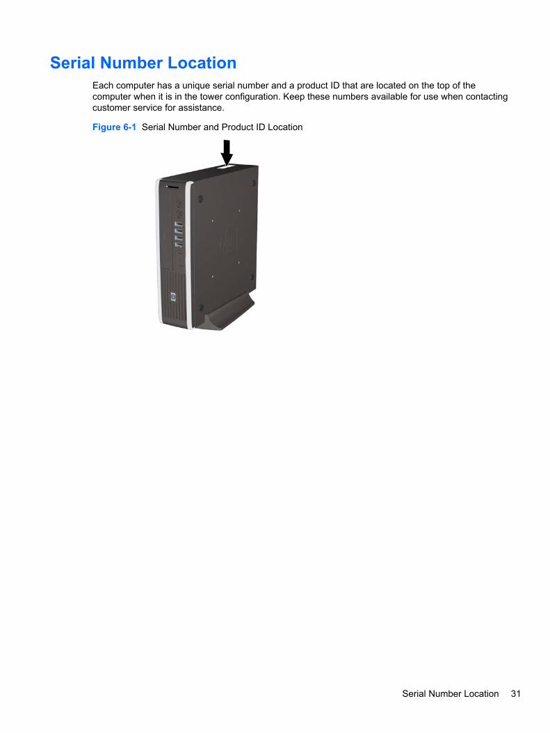
Serial Number LocationEach computer has a unique serial number and a product ID that are located on the top of thecomputer when it is in the tower configuration. Keep these numbers available for use when contactingcustomer service for assistance.
Figure 6-1 Serial Number and Product ID Location
Serial Number Location 31

Security Lock ProvisionsNOTE: For information on data security features, refer to the Desktop Management Guide and theHP ProtectTools Security Manager Guide (some models) at http://www.hp.com.
The security locks displayed below and on the following pages can be used to secure the computer.
Installing a Security Lock
HP/Kensington MicroSaver Security Cable LockThere are two cable lock slots on the rear of the computer. The slot next to the thumbscrew should beused when there is no port cover. The slot on the far right should be used when a port cover isinstalled.
Figure 6-2 Installing a Cable Lock with No Port Cover
Figure 6-3 Installing a Cable with a Port Cover Installed
32 Chapter 6 Removal and Replacement Procedures

PadlockFigure 6-4 Installing a Padlock
HP Business PC Security Lock1. Fasten the security cable by looping it around a stationary object.
Figure 6-5 Securing the Cable to a Fixed Object
Security Lock Provisions 33

2. Thread the keyboard and mouse cables through the lock.
Figure 6-6 Threading the Keyboard and Mouse Cables
3. Screw the lock to the chassis using the screw provided.
Figure 6-7 Attaching the Lock to the Chassis
34 Chapter 6 Removal and Replacement Procedures

4. Insert the plug end of the security cable into the lock (1) and push the button in (2) to engage thelock. Use the key provided to disengage the lock.
Figure 6-8 Engaging the Lock
Security Lock Provisions 35
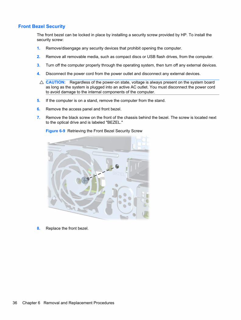
Front Bezel SecurityThe front bezel can be locked in place by installing a security screw provided by HP. To install thesecurity screw:
1. Remove/disengage any security devices that prohibit opening the computer.
2. Remove all removable media, such as compact discs or USB flash drives, from the computer.
3. Turn off the computer properly through the operating system, then turn off any external devices.
4. Disconnect the power cord from the power outlet and disconnect any external devices.
CAUTION: Regardless of the power-on state, voltage is always present on the system boardas long as the system is plugged into an active AC outlet. You must disconnect the power cordto avoid damage to the internal components of the computer.
5. If the computer is on a stand, remove the computer from the stand.
6. Remove the access panel and front bezel.
7. Remove the black screw on the front of the chassis behind the bezel. The screw is located nextto the optical drive and is labeled "BEZEL."
Figure 6-9 Retrieving the Front Bezel Security Screw
8. Replace the front bezel.
36 Chapter 6 Removal and Replacement Procedures

9. Install the security screw through the middle front bezel release tab and into the chassis tosecure the front bezel in place.
Figure 6-10 Installing the Front Bezel Security Screw
10. Replace the access panel.
11. If the computer was on a stand, replace the stand.
12. Reconnect the power cord and turn on the computer.
13. Lock any security devices that were disengaged when the access panel was removed.
Security Lock Provisions 37

Computer Access PanelTo access internal components, you must remove the access panel:
1. Prepare the computer for disassembly (Preparation for Disassembly on page 30).
2. Loosen the thumbscrew on the rear of the computer (1), slide the access panel toward the frontof the computer, and then lift it off (2).
Figure 6-11 Removing the Computer Access Panel
To install the access panel, reverse the removal procedure.
38 Chapter 6 Removal and Replacement Procedures

Front Bezel1. Prepare the computer for disassembly (Preparation for Disassembly on page 30).
2. Remove the computer access panel (Computer Access Panel on page 38).
3. Lift up the three tabs on the side of the bezel (1), then rotate the bezel off the chassis (2).
Figure 6-12 Removing the Front Bezel
To install the front bezel, reverse the removal procedure.
Front Bezel 39

Bezel BlankOn some models, there is a bezel blank covering the external drive bay that needs to be removedbefore installing a drive. To remove a bezel blank:
1. Remove the computer access panel (Computer Access Panel on page 38).
2. Remove the front bezel (Front Bezel on page 39).
3. Push the two retaining tabs that hold the bezel blank in place towards the outer right edge of thebezel (1) and pull the bezel blank inwards to remove it (2).
Figure 6-13 Removing a Bezel Blank
40 Chapter 6 Removal and Replacement Procedures

Installing Additional MemoryThe computer comes with double data rate 3 synchronous dynamic random access memory (DDR3-SDRAM) small outline dual inline memory modules (SODIMMs).
SODIMMsThe memory sockets on the system board can be populated with up to two industry-standardSODIMMs. These memory sockets are populated with at least one preinstalled SODIMM. To achievethe maximum memory support, you can populate the system board with up to 8-GB of memory.
DDR3-SDRAM SODIMMsFor proper system operation, the SODIMMs must be:
● industry-standard 204-pin
● unbuffered non-ECC PC3-8500 DDR3-1066 MHz-compliant or PC3-10600 DDR3-1333 MHz-compliant
● 1.5 volt DDR3-SDRAM SODIMMs
The DDR3-SDRAM SODIMMs must also:
● support CAS latency 7 DDR3 1066 MHz (7-7-7 timing) and CAS latency 9 DDR3 1333 MHz(9-9-9 timing)
● contain the mandatory Joint Electronic Device Engineering Council (JEDEC) specification
In addition, the computer supports:
● 512-Mbit, 1-Gbit, and 2-Gbit non-ECC memory technologies
● single-sided and double-sided SODIMMS
● SODIMMs constructed with x8 and x16 devices; SODIMMs constructed with x4 SDRAM are notsupported
NOTE: The system will not operate properly if you install unsupported SODIMMs.
Installing Additional Memory 41

Populating SODIMM SocketsThere are two SODIMM sockets on the system board, with one socket per channel. The sockets arelabeled XMM1 and XMM3. The XMM1 socket operates in memory channel A. The XMM3 socketoperates in memory channel B.
Figure 6-14 SODIMM Socket Locations
Table 6-1 SODIMM Socket Locations
Item Description Socket Color
1 SODIMM1 socket, Channel A Black
2 SODIMM3 socket, Channel B White
NOTE: A SODIMM must occupy the black XMM1 socket. Otherwise, thesystem will display a POST error message indicating that a memory modulemust be installed in the black socket.
The system will automatically operate in single channel mode, dual channel mode, or flex mode,depending on how the SODIMMs are installed.
● The system will operate in single channel mode if the SODIMM sockets are populated in onechannel only.
● The system will operate in a higher-performing dual channel mode if the memory capacity of theSODIMM in Channel A is equal to the memory capacity of the SODIMM in Channel B.
● The system will operate in flex mode if the memory capacity of the SODIMM in Channel A is notequal to the memory capacity of the SODIMM in Channel B. In flex mode, the channel populatedwith the least amount of memory describes the total amount of memory assigned to dualchannel and the remainder is assigned to single channel. If one channel will have more memorythan the other, the larger amount should be assigned to channel A.
● In any mode, the maximum operational speed is determined by the slowest SODIMM in thesystem.
42 Chapter 6 Removal and Replacement Procedures
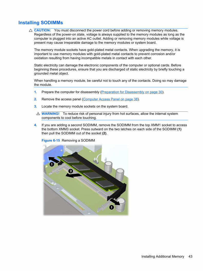
Installing SODIMMsCAUTION: You must disconnect the power cord before adding or removing memory modules.Regardless of the power-on state, voltage is always supplied to the memory modules as long as thecomputer is plugged into an active AC outlet. Adding or removing memory modules while voltage ispresent may cause irreparable damage to the memory modules or system board.
The memory module sockets have gold-plated metal contacts. When upgrading the memory, it isimportant to use memory modules with gold-plated metal contacts to prevent corrosion and/oroxidation resulting from having incompatible metals in contact with each other.
Static electricity can damage the electronic components of the computer or optional cards. Beforebeginning these procedures, ensure that you are discharged of static electricity by briefly touching agrounded metal object.
When handling a memory module, be careful not to touch any of the contacts. Doing so may damagethe module.
1. Prepare the computer for disassembly (Preparation for Disassembly on page 30).
2. Remove the access panel (Computer Access Panel on page 38).
3. Locate the memory module sockets on the system board.
WARNING! To reduce risk of personal injury from hot surfaces, allow the internal systemcomponents to cool before touching.
4. If you are adding a second SODIMM, remove the SODIMM from the top XMM1 socket to accessthe bottom XMM3 socket. Press outward on the two latches on each side of the SODIMM (1)then pull the SODIMM out of the socket (2).
Figure 6-15 Removing a SODIMM
Installing Additional Memory 43

5. Slide the new SODIMM into the socket at approximately a 30° angle (1) then press the SODIMMdown (2) so that the latches lock it in place.
Figure 6-16 Installing a SODIMM
NOTE: A memory module can be installed in only one way. Match the notch on the modulewith the tab on the memory socket.
A SODIMM must occupy the XMM1 (top) socket.
6. Replace the SODIMM in the DIMM1 socket if it was removed.
7. Replace the access panel.
8. If the computer was on a stand, replace the stand.
9. Reconnect the power cord and turn on the computer.
10. Lock any security devices that were disengaged when the computer cover or access panel wasremoved.
The computer automatically recognizes the additional memory when you turn on the computer.
44 Chapter 6 Removal and Replacement Procedures

Cable ManagementAlways follow good cable management practices when working inside the computer.
● Keep cables away from major heat sources like the heat sink.
● Do not jam cables on top of expansion cards or memory modules. Printed circuit cards like theseare not designed to take excessive pressure on them.
● Keep cables clear of sliding or moveable parts to prevent their being cut or crimped when theparts are moved.
● Do not bend any cable sharply. A sharp bend can break the internal wires.
● Never bend a SATA data cable tighter than a 30 mm (1.18 in) radius.
● Never crease a SATA data cable.
● Do not rely on components like the drive cage, power supply, or computer cover to push cablesdown into the chassis. Always position the cables to lay properly by themselves.
System board connectors are color-coded to make it easier to find the proper connection.
Connector Name Connector Color Description
CHFAN Maroon Front chassis fan
CHFAN2 Brown Rear chassis fan
SPKR White Internal speaker
SATA0 Black Hard drive data and power
SATA1 White Optical drive data
SATA PWR1 White Optical drive power
Cable Management 45

Replacing the Optical DriveThe Ultra-Slim Desktop uses a slimline Serial ATA (SATA) optical drive.
Removing the Existing Optical Drive1. Prepare the computer for disassembly (Preparation for Disassembly on page 30).
2. If the computer is on a stand, remove the computer from the stand and lay the computer down.
3. Remove the computer access panel (Computer Access Panel on page 38).
4. Disconnect the cable on the rear of the optical drive (1), push the green release latch on the rightrear side of the drive toward the center of the drive (2), then slide the drive forward and out ofthe bay through the front bezel (3).
Figure 6-17 Removing the Optical Drive
46 Chapter 6 Removal and Replacement Procedures

Preparing the New Optical DriveBefore the new optical drive can be used, the release latch must be attached.
1. Peel the backing off the adhesive on the release latch.
2. Without allowing the release latch to touch the optical drive, carefully align the holes on therelease latch with the pins on the side of the optical drive. Make sure the release latch isoriented properly.
3. Insert the pin at the front of the optical drive into the hole at the end of the release latch, andpress firmly.
4. Insert the second pin, and press the entire release latch firmly to fasten the latch securely to theoptical drive.
Figure 6-18 Aligning the Release Latch
Replacing the Optical Drive 47
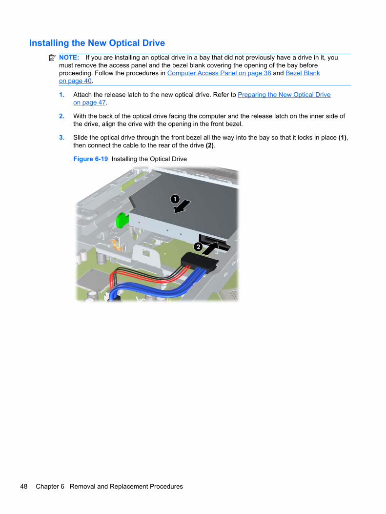
Installing the New Optical DriveNOTE: If you are installing an optical drive in a bay that did not previously have a drive in it, youmust remove the access panel and the bezel blank covering the opening of the bay beforeproceeding. Follow the procedures in Computer Access Panel on page 38 and Bezel Blankon page 40.
1. Attach the release latch to the new optical drive. Refer to Preparing the New Optical Driveon page 47.
2. With the back of the optical drive facing the computer and the release latch on the inner side ofthe drive, align the drive with the opening in the front bezel.
3. Slide the optical drive through the front bezel all the way into the bay so that it locks in place (1),then connect the cable to the rear of the drive (2).
Figure 6-19 Installing the Optical Drive
48 Chapter 6 Removal and Replacement Procedures
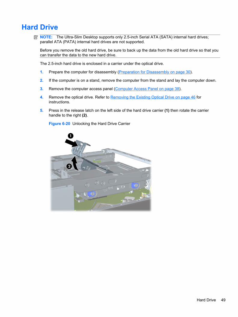
Hard DriveNOTE: The Ultra-Slim Desktop supports only 2.5-inch Serial ATA (SATA) internal hard drives;parallel ATA (PATA) internal hard drives are not supported.
Before you remove the old hard drive, be sure to back up the data from the old hard drive so that youcan transfer the data to the new hard drive.
The 2.5-inch hard drive is enclosed in a carrier under the optical drive.
1. Prepare the computer for disassembly (Preparation for Disassembly on page 30).
2. If the computer is on a stand, remove the computer from the stand and lay the computer down.
3. Remove the computer access panel (Computer Access Panel on page 38).
4. Remove the optical drive. Refer to Removing the Existing Optical Drive on page 46 forinstructions.
5. Press in the release latch on the left side of the hard drive carrier (1) then rotate the carrierhandle to the right (2).
Figure 6-20 Unlocking the Hard Drive Carrier
Hard Drive 49

6. Lift the hard drive carrier straight up and out of the chassis.
Figure 6-21 Removing the Hard Drive Carrier
7. Remove the four guide screws from the sides of the hard drive carrier.
Figure 6-22 Removing the Guide Screws
8. Lift the hard drive up to the top of the carrier (1) and slide the drive out of the carrier (2).
Figure 6-23 Removing the Hard Drive from the Carrier
50 Chapter 6 Removal and Replacement Procedures

9. Position the hard drive so that the top of the hard drive is up against the top of the carrier (1) sothat the circuit board on the bottom of the hard drive does not come in contact wit the tabs on thebottom of the carrier, then slide the new hard drive into the carrier (2).
CAUTION: Do not allow the circuit board on the bottom of the hard drive to scrape along thetabs on the bottom of the carrier when sliding the hard drive into the carrier. Doing so can causeirreparable damage to the hard drive.
Figure 6-24 Sliding the Hard Drive into the Carrier
10. Set the hard drive down into the bottom of the carrier (1), then replace the four guide screws onthe sides of the carrier to secure the drive in the carrier (2).
Figure 6-25 Lowering the Hard Drive and Replacing the Guide Screws
Hard Drive 51

11. To place the hard drive carrier back in the chassis, align the guide screws with the slots on thedrive bay, drop the carrier straight down into the drive bay (1), and press the handle on thecarrier all the way down (2) so that the drive is properly seated and locked in place.
Figure 6-26 Installing the Hard Drive Carrier
12. Replace the optical drive and reconnect the cable on the back of the optical drive.
13. Replace the computer access panel.
14. If the computer was on a stand, replace the stand.
15. Reconnect the power cord and turn on the computer.
16. Lock any security devices that were disengaged when the computer cover or access panel wasremoved.
NOTE: No configuration of the SATA hard drive is necessary; the computer automaticallyrecognizes it the next time you turn on the computer.
52 Chapter 6 Removal and Replacement Procedures

Hard Drive CageThe drive cage sits behind the USB ports on the front of the chassis.
1. Prepare the computer for disassembly (Preparation for Disassembly on page 30).
2. Remove the computer access panel (Computer Access Panel on page 38).
3. Remove the optical drive and connector (Removing the Existing Optical Drive on page 46).
4. Remove the hard drive (Hard Drive on page 49).
5. Remove the two Torx T15 screws that secure the cage to the chassis (1), lift the tab (2) on thehard drive cage, slide the cage toward the rear of the unit (3), and then pull the cage up and outof the chassis.
Figure 6-27 Removing the hard drive cage
To install the hard drive cage, reverse the removal procedures.
Hard Drive Cage 53

Port CoverAn optional rear port cover is available for the computer.
To install the port cover:
1. Thread the cables through the bottom hole on the port cover (1) and connect the cables to therear ports on the computer.
2. Insert the hooks on the port cover into the slots on the rear of the chassis, then slide the cover tothe right to secure it in place (2).
Figure 6-28 Installing a Port Cover
NOTE: For security purposes, you can install an optional cable lock to the chassis that locks theport cover and secures the computer. See Installing a Security Lock on page 32.
The port cover is secured in place by a retention lever just inside the port cover opening. To removethe port cover, pull the lever back towards the port cover opening (1), then slide the cover to the leftand off the computer (2).
Figure 6-29 Removing a Port Cover
54 Chapter 6 Removal and Replacement Procedures
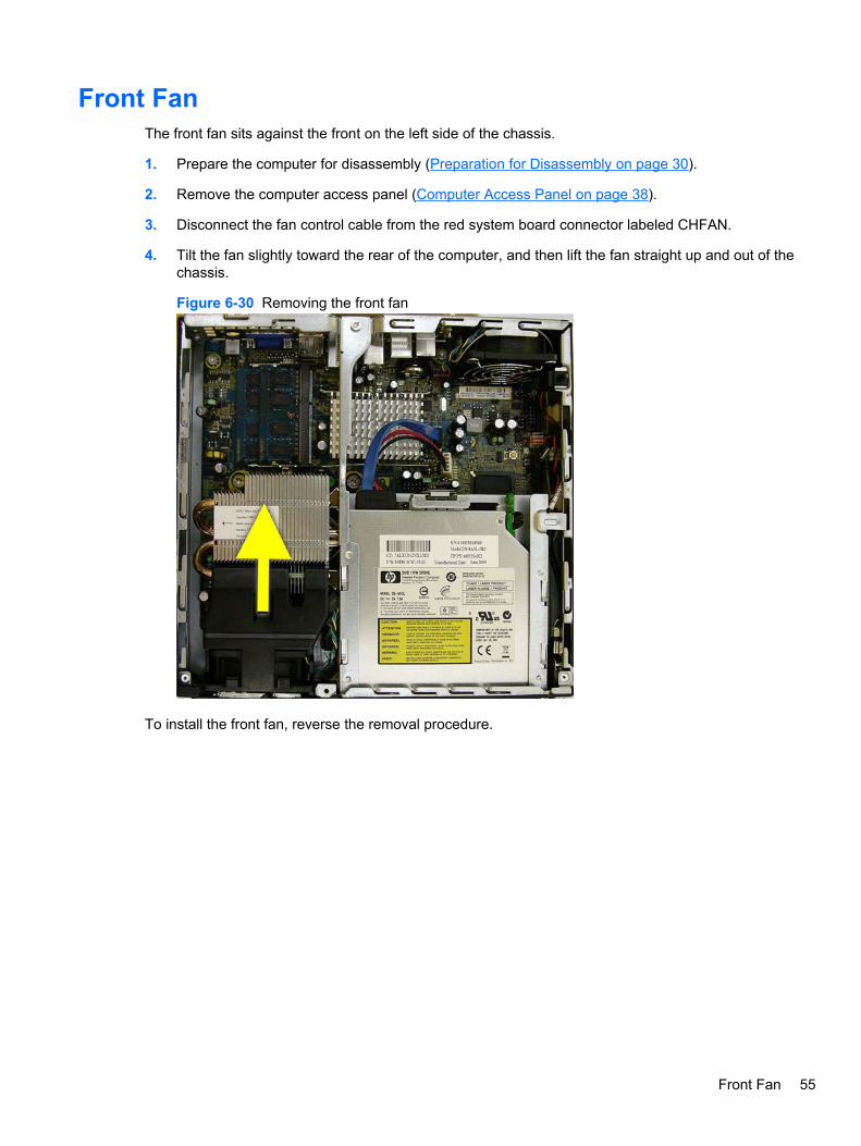
Front FanThe front fan sits against the front on the left side of the chassis.
1. Prepare the computer for disassembly (Preparation for Disassembly on page 30).
2. Remove the computer access panel (Computer Access Panel on page 38).
3. Disconnect the fan control cable from the red system board connector labeled CHFAN.
4. Tilt the fan slightly toward the rear of the computer, and then lift the fan straight up and out of thechassis.
Figure 6-30 Removing the front fan
To install the front fan, reverse the removal procedure.
Front Fan 55

Card ReaderThe card reader is secured to the front right corner of the chassis.
1. Prepare the computer for disassembly (Preparation for Disassembly on page 30).
2. Remove the computer access panel (Computer Access Panel on page 38).
3. Remove the front bezel (Front Bezel on page 39).
4. Disconnect the cable from the black system board connector labeled MEDIA.
5. On the outside of the chassis, remove the one torx T15 screw that secures the card reader tothe chassis.
Figure 6-31 Removing the card reader
6. Pull the reader away from the front of the chassis while threading the cable through the slot inthe front of the chassis.
To install the card reader, reverse the removal procedure.
56 Chapter 6 Removal and Replacement Procedures

SpeakerThe speaker is secured to the front of the chassis between the fan and the I/O ports.
1. Prepare the computer for disassembly (Preparation for Disassembly on page 30).
2. Remove the computer access panel (Computer Access Panel on page 38).
3. Remove the front bezel (Front Bezel on page 39).
4. Disconnect the speaker cable from the white system board connector labeled SPKR.
5. From the outside of the chassis, remove the two torx T8 screws that secure the speaker to thechassis, and then from the inside of the chassis, slide the speaker up and lift it out.
Figure 6-32 Removing the speaker
To install the speaker, reverse the removal procedure.
Speaker 57

Heat sinkThe heat sink is secured by four Torx T15 screws. It does not have an attached fan.
1. Prepare the computer for disassembly (Preparation for Disassembly on page 30).
2. Remove the computer access panel (Computer Access Panel on page 38).
3. Lift the front fan up and place it on top of the optical drive to access the front bezel release tabs.You do not need to disconnect the fan cable from the system board.
4. Loosen the four Torx T15 screws that secure the heat sink to the system board, and then lift theheat sink from the system board.
Figure 6-33 Removing the heat sink
CAUTION: Heat sink retaining screws should be removed in diagonally opposite pairs (as inan X) to even the downward forces on the processor to avoid damage that could requirereplacing the system board.
5. Lay the heat sink on its top in a safe area to prevent the thermal grease from contaminating thework surface.
If reusing the existing heat sink go to step 1.
If using a new heat sink, go to step 3.
1. If reusing the existing heat sink, clean bottom of the heat sink and apply the thermal greaseprovided in the spares kit to the top of the processor.
2. Position the heat sink atop the processor.
3. If using a new heat sink, remove the protective covering from the bottom of the heat sink andplace it in position atop the processor.
4. Secure the heat sink to the system board and system board tray with the 4 captive screws andattach the heat sink control cable and the thermal sensor cable to the system board.
58 Chapter 6 Removal and Replacement Procedures
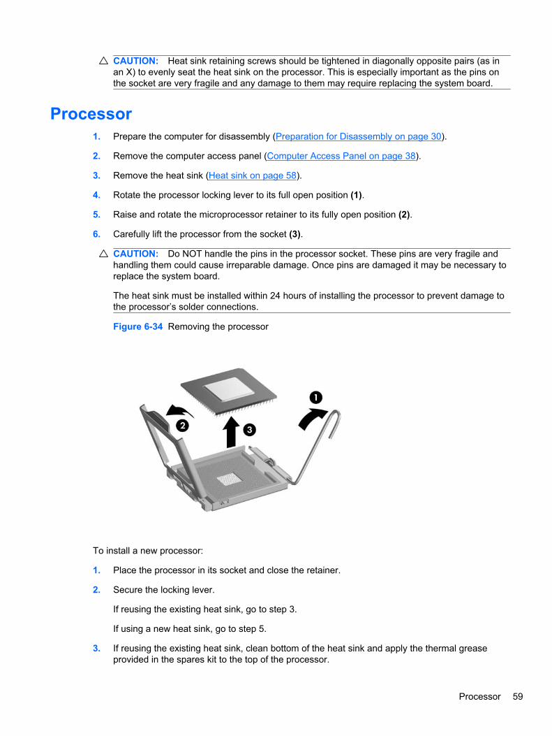
CAUTION: Heat sink retaining screws should be tightened in diagonally opposite pairs (as inan X) to evenly seat the heat sink on the processor. This is especially important as the pins onthe socket are very fragile and any damage to them may require replacing the system board.
Processor1. Prepare the computer for disassembly (Preparation for Disassembly on page 30).
2. Remove the computer access panel (Computer Access Panel on page 38).
3. Remove the heat sink (Heat sink on page 58).
4. Rotate the processor locking lever to its full open position (1).
5. Raise and rotate the microprocessor retainer to its fully open position (2).
6. Carefully lift the processor from the socket (3).
CAUTION: Do NOT handle the pins in the processor socket. These pins are very fragile andhandling them could cause irreparable damage. Once pins are damaged it may be necessary toreplace the system board.
The heat sink must be installed within 24 hours of installing the processor to prevent damage tothe processor’s solder connections.
Figure 6-34 Removing the processor
To install a new processor:
1. Place the processor in its socket and close the retainer.
2. Secure the locking lever.
If reusing the existing heat sink, go to step 3.
If using a new heat sink, go to step 5.
3. If reusing the existing heat sink, clean bottom of the heat sink and apply the thermal greaseprovided in the spares kit to the top of the processor.
Processor 59

4. Position the heat sink atop the processor.
5. If using a new heat sink, remove the protective covering from the bottom of the heat sink andplace it in position atop the processor.
6. Secure the heat sink to the system board and system board tray with the 4 captive screws andattach the heat sink control cable to the system board.
CAUTION: Heat sink retaining screws should be tightened in diagonally opposite pairs (as inan X) to evenly seat the heat sink on the processor. This is especially important as the pins onthe socket are very fragile and any damage to them may require replacing the system board.
NOTE: After installing a new processor onto the system board, always update the system ROM toensure that the latest version of the BIOS is being used on the computer. The latest system BIOS canbe found on the Web at: http://h18000.www1.hp.com/support/files.
60 Chapter 6 Removal and Replacement Procedures
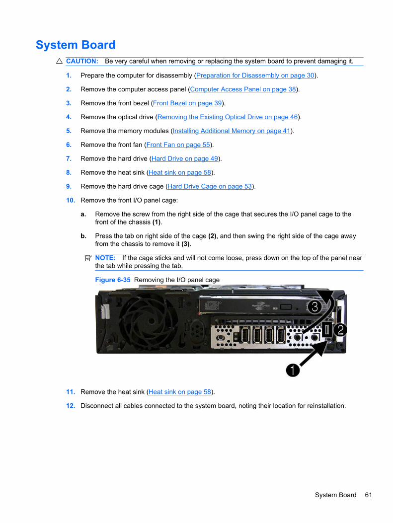
System BoardCAUTION: Be very careful when removing or replacing the system board to prevent damaging it.
1. Prepare the computer for disassembly (Preparation for Disassembly on page 30).
2. Remove the computer access panel (Computer Access Panel on page 38).
3. Remove the front bezel (Front Bezel on page 39).
4. Remove the optical drive (Removing the Existing Optical Drive on page 46).
5. Remove the memory modules (Installing Additional Memory on page 41).
6. Remove the front fan (Front Fan on page 55).
7. Remove the hard drive (Hard Drive on page 49).
8. Remove the heat sink (Heat sink on page 58).
9. Remove the hard drive cage (Hard Drive Cage on page 53).
10. Remove the front I/O panel cage:
a. Remove the screw from the right side of the cage that secures the I/O panel cage to thefront of the chassis (1).
b. Press the tab on right side of the cage (2), and then swing the right side of the cage awayfrom the chassis to remove it (3).
NOTE: If the cage sticks and will not come loose, press down on the top of the panel nearthe tab while pressing the tab.
Figure 6-35 Removing the I/O panel cage
11. Remove the heat sink (Heat sink on page 58).
12. Disconnect all cables connected to the system board, noting their location for reinstallation.
System Board 61
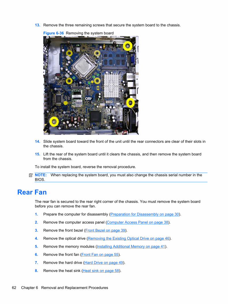
13. Remove the three remaining screws that secure the system board to the chassis.
Figure 6-36 Removing the system board
14. Slide system board toward the front of the unit until the rear connectors are clear of their slots inthe chassis.
15. Lift the rear of the system board until it clears the chassis, and then remove the system boardfrom the chassis.
To install the system board, reverse the removal procedure.
NOTE: When replacing the system board, you must also change the chassis serial number in theBIOS.
Rear FanThe rear fan is secured to the rear right corner of the chassis. You must remove the system boardbefore you can remove the rear fan.
1. Prepare the computer for disassembly (Preparation for Disassembly on page 30).
2. Remove the computer access panel (Computer Access Panel on page 38).
3. Remove the front bezel (Front Bezel on page 39).
4. Remove the optical drive (Removing the Existing Optical Drive on page 46).
5. Remove the memory modules (Installing Additional Memory on page 41).
6. Remove the front fan (Front Fan on page 55).
7. Remove the hard drive (Hard Drive on page 49).
8. Remove the heat sink (Heat sink on page 58).
62 Chapter 6 Removal and Replacement Procedures

9. Remove the hard drive cage (Hard Drive Cage on page 53).
10. Remove the system board (System Board on page 61).
11. Disconnect the fan control cable from the red/brown system board connector labeled CHFAN2.
12. From the outside of the chassis, remove the four Phillips screws that secure the fan to thechassis, then from the inside of the chassis, slide the fan forward and lift it up and out of thechassis.
Figure 6-37 Removing the rear fan
To install the rear fan, reverse the removal procedure.
BatteryThe battery that comes with your computer provides power to the real-time clock and has a lifetime ofabout three years. When replacing the battery, use a battery equivalent to the battery originallyinstalled on the computer. The computer comes with a 3-volt lithium coin cell battery.
NOTE: The lifetime of the lithium battery can be extended by plugging the computer into a live ACwall socket. The lithium battery is only used when the computer is NOT connected to AC power.
WARNING! This computer contains an internal lithium manganese dioxide battery. There is a risk offire and burns if the battery is not handled properly. To reduce the risk of personal injury:
Do not attempt to recharge the battery.
Do not expose to temperatures higher than 140°F (60°C).
Do not disassemble, crush, puncture, short external contacts, or dispose of in fire or water.
Replace the battery only with the HP spare designated for this product.
CAUTION: Before replacing the battery, it is important to back up the computer CMOS settings.When the battery is removed or replaced, the CMOS settings will be cleared. Refer to ComputerSetup (F10) Utility on page 6 for information on backing up the CMOS settings.
NOTE: HP encourages customers to recycle used electronic hardware, HP original print cartridges,and rechargeable batteries. For more information about recycling programs, go to http://www.hp.com/recycle.
Battery 63

CAUTION: Static electricity can damage the electronic components of the computer or optionalequipment. Before beginning these procedures, ensure that you are discharged of static electricity bybriefly touching a grounded metal object.
1. Prepare the computer for disassembly (Preparation for Disassembly on page 30).
2. Remove the computer access panel (Computer Access Panel on page 38).
3. Pull back on the clip (1) that holds the battery in place, then remove the battery (2).
4. Insert the new battery and position the clip back in place.
Figure 6-38 Removing the battery
5. After the battery has been replaced, reverse the disassembly procedure.
6. Plug in the computer and turn on power to the computer.
7. Reset the date and time, your passwords, and any special system setups, using ComputerSetup. Refer to the Computer Setup (F10) Utility Guide.
64 Chapter 6 Removal and Replacement Procedures

Changing from Desktop to Tower Configuration1. Prepare the computer for disassembly (Preparation for Disassembly on page 30).
2. Place the computer firmly down into the stand.
Figure 6-39 Placing the Computer on the Stand
3. Reconnect the external equipment, plug the power cord into a power outlet, and turn thecomputer on.
4. Lock any security devices that were disengaged when the computer cover or access panel wasremoved.
To change from the tower configuration to the desktop configuration, reverse the previous steps.
NOTE: An optional Quick Release mounting bracket is available from HP for mounting the computerto a wall, desk, or swing arm.
Changing from Desktop to Tower Configuration 65

Power Supply, ExternalThe USDT chassis uses an external power supply.
WARNING! To reduce potential safety issues, only the power supply provided with the computer, areplacement power supply provided by HP, or a power supply purchased as an accessory from HPshould be used with the computer.
66 Chapter 6 Removal and Replacement Procedures

A Connector Pin Assignments
This appendix contains the pin assignments for many computer and workstation connectors. Some ofthese connectors may not be used on the product being serviced.
KeyboardConnector and Icon Pin Signal
1
2
3
Data
Unused
Ground
4
5
6
+5 VDC
Clock
Unused
MouseConnector and Icon Pin Signal
1
2
3
Data
Unused
Ground
4
5
6
+5 VDC
Clock
Unused
Ethernet BNCConnector and Icon Pin Signal
1
2
Data
Ground
Keyboard 67

Ethernet RJ-45Connector and Icon Pin Signal
1
2
3
4
(+) Transmit Data
(-) Transmit Data
(+) Receive Data
Unused
5
6
7
8
Unused
(-) Receive Data
Unused
Unused
Serial Interface, Powered and Non-PoweredConnector and Icon Pin Signal
1
2
3
Carrier Detect (12V if powered)
Receive Data
Transmit Data
4
5
6
Data Terminal Ready
Signal Ground
Data Set Ready
7
8
9
Request to Send
Clear to Send
Ring Indicator (5V if powered)
USBConnector and Icon Pin Signal
1
2
3
4
+5 VDC
- Data
+ Data
Ground
68 Appendix A Connector Pin Assignments
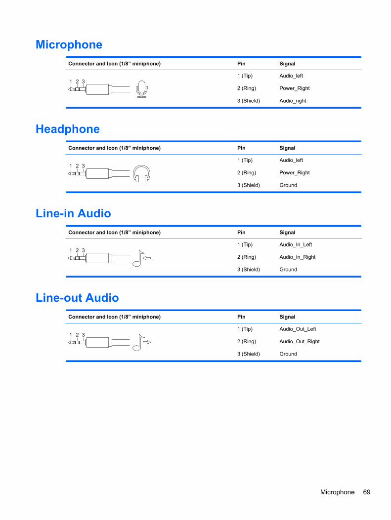
MicrophoneConnector and Icon (1/8” miniphone) Pin Signal
1 2 31 (Tip)
2 (Ring)
3 (Shield)
Audio_left
Power_Right
Audio_right
HeadphoneConnector and Icon (1/8” miniphone) Pin Signal
1 2 31 (Tip)
2 (Ring)
3 (Shield)
Audio_left
Power_Right
Ground
Line-in AudioConnector and Icon (1/8” miniphone) Pin Signal
1 2 31 (Tip)
2 (Ring)
3 (Shield)
Audio_In_Left
Audio_In_Right
Ground
Line-out AudioConnector and Icon (1/8” miniphone) Pin Signal
1 2 31 (Tip)
2 (Ring)
3 (Shield)
Audio_Out_Left
Audio_Out_Right
Ground
Microphone 69

MonitorConnector and Icon
Pin Signal Pin Signal
1
2
3
4
Red Analog
Green Analog
Blue Analog
Not used
9
10
11
12
+5V (fused)
Ground
Not used
DDC Serial Data
5
6
7
8
Ground
Ground
Ground
Ground
13
14
15
Horizontal Sync
Vertical Sync
DDC Serial Clock
DisplayPortConnector and Icon
TOP ROW BOTTOM ROW
Pin Signal Type Pin Name Pin Signal Type Pin Name
1
3
5
7
9
Ground
Out
Out
Ground
Out
Ground
GND
ML Lane 0 (p)
ML Lane 0 (n)
GND
ML Lane 1 (p)
2
4
6
8
10
In
CONFIG
CONFIG
GND
Out
Hot Plug Detect
CONFIG 1
CONFIG 2
GND
ML Lane 3 (p)
11
13
15
17
19
Out
Ground
Out
Out
Ground
ML Lane 1 (n)
GND
ML Lane 2 (p)
ML Lane 2 (n)
GND
12
14
16
18
20
Out
GND
I/O
I/O
PWR Out
ML Lane 3 (n)
GND
AUX CH (p)
AUX CH (n)
DP_PWR
70 Appendix A Connector Pin Assignments

4-Pin Power (for CPU)Connector and Icon Pin Signal
1
2
3
4
GND
GND
+12V CPU
-12V CPU
6-Pin Power (for CPU) (CMT, SFF)Connector and Icon Pin Signal
64
1
2
3
4
5
6
GND
GND
GND
12V CPU
12V CPU
+12V
SATA Data and PowerDrive Connector
Pin Signal Pin Signal Pin Signal Pin Signal
S1
S5
Ground
B-
S2
S6
A+
B+
S3
S7
A-
Ground
S4 Ground
P1
P5
P9
P13
Ground
B-
V 5
V 12
P2
P6
P10
P14
V 3.3
Ground
Ground
V12
P3
P7
P11
P15
V 3.3
V 5
Reserved
V 12
P4
P8
P12
Ground
V 5
Ground
S = Data, P = Power
4-Pin Power (for CPU) 71

PCI Expressx1, x4, x8, and x16 PCI Express Connector
Pin A
Pin Signal Pin Signal Pin Signal Pin Signal Pin Signal
1
2
3
4
5
PRSNT1
+12V
+12V
GND
JTAG2
6
7
8
9
10
JTAG3
JTAG4
JTAG5
+3.3V
+3.3V
11
12
13
14
15
PERST#
GND
REFCLK+
REFCLK-
GND
16
17
18
19
20
PERp0
PERn0
GND
RSVD
GND
21
22
23
24
25
PERp1
PERn1
GND
GND
PERp2
26
27
28
29
30
PERn(2)
GND
GND
PERp3
PERn3
31
32
33
34
35
GND
RSVD
RSVD
GND
PERp4
36
37
38
39
40
PERn4
GND
GND
PERp5
PERn5
41
42
43
44
45
GND
GND
PERp6
PERn6
GND
46
47
48
49
50
GND
PERp7
PERn7
GND
RSVD
51
52
53
54
55
GND
PERp8
PERN8
GND
GND
56
57
58
59
60
PERp9
PERn9
GND
GND
PERp10
61
62
63
64
65
PERn10
GND
GND
PERp11
PERn11
66
67
68
69
70
GND
GND
PERp12
PERn12
GND
71
72
73
74
75
GND
PERp13
PERn13
GND
GND
76
77
78
79
80
PERp14
PERn14
GND
GND
PERp15
81
82
PERn15
GND
NOTE: x1 PCI Express uses pins 1-18
x4 PCI Express uses pins 1-32
x8 PCI Express uses pins 1-49
x16 PCI Express uses pins 1-8
72 Appendix A Connector Pin Assignments

PCI Expressx1, x4, x8, and x16 PCI Express Connector
Pin B
Pin Signal Pin Signal Pin Signal Pin Signal Pin Signal
1
2
3
4
5
+12V
+12V
RSVD
GND
SMCLK
6
7
8
9
10
SMDAT
GND
+3.3 V
JTAG1
3.3vAux
11
12
13
14
15
WAKE#
RSVD
GND
PETp0
PETn0
16
17
18
19
20
GND
GND
GND
PETp1
PETn1
21
22
23
24
25
GND
GND
PETp2
PETn2
GND
26
27
28
29
30
GND
PETp3
PETn3
GND
RSVD
31
32
33
34
35
PRSNT2#
GND
PETp4
PETn4
GND
36
37
38
39
40
GND
PETp5
PETn5
GND
GND
41
42
43
44
45
PETp6
PRTn6
GND
GND
PETp7
46
47
48
49
50
PETn7
GND
PRSNT2#
GND
PETp8
51
52
53
54
55
PETn8
GND
GND
PETp9
PETn9
56
57
58
59
60
GND
GND
PETp10
PETn10
GND
61
62
63
64
65
GND
PETp11
PETn11
GND
GND
66
67
68
69
70
PETp12
PETn12
GND
GND
PETp13
71
72
73
74
75
PETn13
GND
GND
PETp14
PETn14
76
77
78
79
80
GND
GND
PETp15
PETn15
GND
81
82
PRSNT2#
RSVD
NOTE: x1 PCI Express uses pins 1-18
x4 PCI Express uses pins 1-32
x8 PCI Express uses pins 1-49
x16 PCI Express uses pins 1-8
PCI Express 73
B Power Cord Set Requirements
The power supplies on some computers have external power switches. The voltage select switchfeature on the computer permits it to operate from any line voltage between 100-120 or 220-240 voltsAC. Power supplies on those computers that do not have external power switches are equipped withinternal switches that sense the incoming voltage and automatically switch to the proper voltage.
The power cord set received with the computer meets the requirements for use in the country whereyou purchased the equipment.
Power cord sets for use in other countries must meet the requirements of the country where you usethe computer.
General RequirementsThe requirements listed below are applicable to all countries:
1. The power cord must be approved by an acceptable accredited agency responsible forevaluation in the country where the power cord set will be installed.
2. The power cord set must have a minimum current capacity of 10A (7A Japan only) and anominal voltage rating of 125 or 250 volts AC, as required by each country’s power system.
3. The diameter of the wire must be a minimum of 0.75 mm2 or 18AWG, and the length of the cordmust be between 1.8 m (6 feet) and 3.6 m (12 feet).
The power cord should be routed so that it is not likely to be walked on or pinched by items placedupon it or against it. Particular attention should be paid to the plug, electrical outlet, and the pointwhere the cord exits from the product.
WARNING! Do not operate this product with a damaged power cord set. If the power cord set isdamaged in any manner, replace it immediately.
Japanese Power Cord RequirementsFor use in Japan, use only the power cord received with this product.
CAUTION: Do not use the power cord received with this product on any other products.
74 Appendix B Power Cord Set Requirements

Country-Specific RequirementsAdditional requirements specific to a country are shown in parentheses and explained below.
Country Accrediting Agency Country Accrediting Agency
Australia (1)
Austria (1)
Belgium (1)
Canada (2)
EANSW
OVE
CEBC
CSA
Italy (1)
Japan (3)
Norway (1)
Sweden (1)
IMQ
METI
NEMKO
SEMKO
Denmark (1)
Finland (1)
France (1)
Germany (1)
DEMKO
SETI
UTE
VDE
Switzerland (1)
United Kingdom (1)
United States (2)
SEV
BSI
UL
1. The flexible cord must be Type HO5VV-F, 3-conductor, 0.75mm2 conductor size. Power cord set fittings (appliancecoupler and wall plug) must bear the certification mark of the agency responsible for evaluation in the country where itwill be used.
2. The flexible cord must be Type SVT or equivalent, No. 18 AWG, 3-conductor. The wall plug must be a two-polegrounding type with a NEMA 5-15P (15A, 125V) or NEMA 6-15P (15A, 250V) configuration.
3. Appliance coupler, flexible cord, and wall plug must bear a “T” mark and registration number in accordance with theJapanese Dentori Law. Flexible cord must be Type VCT or VCTF, 3-conductor, 0.75 mm2 conductor size. Wall plugmust be a two-pole grounding type with a Japanese Industrial Standard C8303 (7A, 125V) configuration.
Country-Specific Requirements 75

C Backup and Recovery
Windows 7 – Backup and RecoveryTo protect your information, use Windows Backup and Restore to back up individual files and folders,back up your entire hard drive (select models only), create system repair discs (select models only),or create system restore points. In case of system failure, you can use the backup files to restore thecontents of your computer.
Windows Backup and Restore provides the following options:
● Creating a system repair disc (select models only)
● Backing up individual files and folders
● Creating a system image (select models only)
● Scheduling automatic backups (select models only)
● Creating system restore points
● Recovering individual files
● Restoring the computer to a previous state
● Recovering information using recovery tools
NOTE: For detailed instructions, perform a search for these topics in Help and Support.
NOTE: In case of system instability, HP recommends that you print the recovery procedures andsave them for later use.
Backing up your informationRecovery after a system failure is as complete as your most current backup. You should createsystem repair discs (select models only) and your initial backup immediately after software setup. Asyou add new software and data files, you should continue to back up your system on a regular basisto maintain a reasonably current backup. The system repair discs (select models only) are used tostart up (boot) the computer and repair the operating system in case of system instability or failure.Your initial and subsequent backups allow you to restore your data and settings if a failure occurs.
You can back up your information to an optional external hard drive, a network drive, or discs.
Note the following when backing up:
● Store personal files in the Documents library, and back it up regularly.
● Back up templates that are stored in their associated programs.
76 Appendix C Backup and Recovery

● Save customized settings that appear in a window, toolbar, or menu bar by taking a screen shotof your settings. The screen shot can be a time-saver if you have to reset your preferences.
To create a screen shot:
1. Display the screen you want to save.
2. Copy the screen image:
To copy only the active window, press Alt+Print Scrn.
To copy the entire screen, press Print Scrn.
3. Open a word-processing document, and then select Edit > Paste.
The screen image is added to the document.
4. Save the document.
● When backing up to discs, use any of the following types of discs (purchased separately): CD-R,CD-RW, DVD+R, DVD+R DL, DVD-R, DVD-R DL, or DVD±RW. The discs you use will dependon the type of optical drive installed in your computer.
NOTE: DVDs and DVDs with double-layer (DL) support store more information than CDs, sousing them for backup reduces the number of recovery discs required.
● When backing up to discs, number each disc before inserting it into the optical drive of thecomputer.
To create a backup using Backup and Restore, follow these steps:
NOTE: The backup process may take over an hour, depending on file size and the speed of thecomputer.
1. Select Start > All Programs > Maintenance > Backup and Restore.
2. Follow the on-screen instructions to set up your backup, create a system image (select modelsonly), or create a system repair disc (select models only).
NOTE: Windows includes the User Account Control feature to improve the security of yourcomputer. You may be prompted for your permission or password for tasks such as installingsoftware, running utilities, or changing Windows settings. Refer to Help and Support for moreinformation.
Performing a recoveryIn case of system failure or instability, the computer provides the following tools to recover your files:
● Windows recovery tools: You can use Windows Backup and Restore to recover information youhave previously backed up. You can also use Windows Startup Repair to fix problems that mightprevent Windows from starting correctly.
● F11 recovery tools: You can use the F11 recovery tools to recover your original hard driveimage. The image includes the Windows operating system and software programs installed atthe factory.
Windows 7 – Backup and Recovery 77

NOTE: If you are unable to boot (start up) your computer and you cannot use the system repairdiscs you previously created (select models only), you must purchase a Windows 7 operating systemDVD to reboot the computer and repair the operating system. For additional information, refer to the“Using a Windows 7 operating system DVD (purchased separately)” section in this guide.
Using the Windows recovery toolsTo recover information you previously backed up, follow these steps:
1. Select Start > All Programs > Maintenance > Backup and Restore.
2. Follow the on-screen instructions to recover your system settings, your computer (select modelsonly), or your files.
NOTE: Windows includes the User Account Control feature to improve the security of yourcomputer. You may be prompted for your permission or password for tasks such as installingsoftware, running utilities, or changing Windows settings. Refer to Help and Support for moreinformation.
To recover your information using Startup Repair, follow these steps:
CAUTION: Using Startup Repair completely erases hard drive contents and reformats the harddrive. All files you have created and any software installed on the computer are permanentlyremoved. When reformatting is complete, the recovery process restores the operating system, as wellas the drivers, software, and utilities from the backup used for recovery.
1. If possible, back up all personal files.
2. If possible, check for the presence of the Windows partition and the HP Recovery partition.
To check for the Windows partition, select Start > Computer.
To check for the HP Recovery partition, select Start, right-click Computer, click Manage, andthen click Disk Management.
NOTE: If the Windows partition and the HP Recovery partition are not listed, you must recoveryour operating system and programs using the Windows 7 operating system DVD and the DriverRecovery disc (both purchased separately). For additional information, refer to the “Using aWindows 7 operating system DVD (purchased separately)” section in this guide.
3. If the Windows partition and the HP Recovery partition are listed, restart the computer, and thenpress F8 before the Windows operating system loads.
4. Select Startup Repair.
5. Follow the on-screen instructions.
NOTE: For additional information on recovering information using the Windows tools, perform asearch for these topics in Help and Support.
Using F11CAUTION: Using F11 completely erases hard drive contents and reformats the hard drive. All filesyou have created and any software installed on the computer are permanently removed. The F11recovery tool reinstalls the operating system and HP programs and drivers that were installed at thefactory. Software not installed at the factory must be reinstalled.
78 Appendix C Backup and Recovery
To recover the original hard drive image using F11, follow these steps:
1. If possible, back up all personal files.
2. If possible, check for the presence of the HP Recovery partition: select Start, right-clickComputer, click Manage, and then click Disk Management.
NOTE: If the HP Recovery partition is not listed, you must recover your operating system andprograms using the Windows 7 operating system DVD and the Driver Recovery disc (bothpurchased separately). For additional information, refer to the “Using a Windows 7 operatingsystem DVD (purchased separately)” section in this guide.
3. Turn on or restart the computer, and then press F11 while the “<F11 = Recovery>” message isdisplayed at the bottom of the screen.
4. Follow the on-screen instructions.
Using a Windows 7 operating system DVD (purchased separately)If you are unable to boot (start up) your computer and you cannot use the system repair discs youpreviously created (select models only), you must purchase a Windows 7 operating system DVD toreboot the computer and repair the operating system. Make sure that your most recent backup(stored on discs or on an external drive) is easily accessible.
CAUTION: Using a Windows 7 operating system DVD completely erases hard drive contents andreformats the hard drive. All files you have created and any software installed on the computer arepermanently removed. When reformatting is complete, the recovery process helps you restore theoperating system, as well as drivers, software, and utilities.
To initiate recovery using a Windows 7 operating system DVD, follow these steps:
NOTE: This process takes several minutes.
1. If possible, back up all personal files.
2. Restart the computer, and then insert the Windows 7 operating system DVD into the opticaldrive before the Windows operating system loads.
3. When prompted, press any keyboard key.
4. Follow the on-screen instructions.
5. Click Next.
6. Select Repair your computer.
7. Follow the on-screen instructions.
Windows 7 – Backup and Recovery 79

Windows Vista – Backup and RecoveryTo protect your information, use the Backup and Restore Center to back up individual files andfolders, back up your entire hard drive (select models only), or create system restore points. In caseof system failure, you can use the backup files to restore the contents of your computer.
The Backup and Restore Center provides the following options:
● Backing up individual files and folders
● Backing up the entire hard drive (select models only)
● Scheduling automatic backups (select models only)
● Creating system restore points
● Recovering individual files
● Restoring the computer to a previous state
● Recovering information using recovery tools
NOTE: For detailed instructions, perform a search for these topics in Help and Support.
NOTE: In case of system instability, HP recommends that you print the recovery procedures andsave them for later use.
Backing up your informationRecovery after a system failure is as complete as your most current backup. You should create yourinitial backup immediately after software setup. As you add new software and data files, you shouldcontinue to back up your system on a regular basis to maintain a reasonably current backup.
You can back up your information to an optional external hard drive, a network drive, or discs.
Note the following when backing up:
● Store personal files in the Documents folder, and back it up regularly.
● Back up templates that are stored in their associated programs.
● Save customized settings that appear in a window, toolbar, or menu bar by taking a screen shotof your settings. The screen shot can be a time-saver if you have to reset your preferences.
To create a screen shot:
1. Display the screen you want to save.
2. Copy the screen image:
To copy only the active window, press Alt+Print Scrn.
To copy the entire screen, press Print Scrn.
3. Open a word-processing document, and then select Edit > Paste.
The screen image is added to the document.
4. Save the document.
80 Appendix C Backup and Recovery

● When backing up to discs, use any of the following types of discs (purchased separately): CD-R,CD-RW, DVD+R, DVD+R DL, DVD-R, DVD-R DL, or DVD±RW. The discs you use will dependon the type of optical drive installed in your computer.
NOTE: DVDs and DVDs with double-layer (DL) support store more information than CDs, sousing them for backup reduces the number of recovery discs required.
● When backing up to discs, number each disc before inserting it into the optical drive of thecomputer.
To create a backup using Backup and Restore Center, follow these steps:
NOTE: The backup process may take over an hour, depending on file size and the speed of thecomputer.
1. Select Start > All Programs > Maintenance > Backup and Restore Center.
2. Follow the on-screen instructions to back up your entire computer (select models only) or yourfiles.
NOTE: Windows includes the User Account Control feature to improve the security of yourcomputer. You may be prompted for your permission or password for tasks such as installingsoftware, running utilities, or changing Windows settings. Refer to Help and Support for moreinformation.
Performing a recoveryIn case of system failure or instability, the computer provides the following tools to recover your files:
● Windows recovery tools: You can use the Backup and Restore Center to recover informationyou have previously backed up. You can also use Windows Startup Repair to fix problems thatmight prevent Windows from starting correctly.
● F11 recovery tools: You can use the F11 recovery tools to recover your original hard driveimage. The image includes the Windows operating system and software programs installed atthe factory.
NOTE: If you are unable to boot (start up) your computer, you must purchase a Windows Vistaoperating system DVD to reboot the computer and repair the operating system. For additionalinformation, refer to the “Using a Windows Vista operating system DVD (purchased separately)”section in this guide.
Using the Windows recovery toolsTo recover information you previously backed up, follow these steps:
1. Click Start > All Programs > Maintenance > Backup and Restore Center.
2. Follow the on-screen instructions to recover your entire computer (select models only) or yourfiles.
NOTE: Windows includes the User Account Control feature to improve the security of yourcomputer. You may be prompted for your permission or password for tasks such as installingsoftware, running utilities, or changing Windows settings. Refer to Help and Support for moreinformation.
To recover your information using Startup Repair, follow these steps:
Windows Vista – Backup and Recovery 81

CAUTION: Using Startup Repair completely erases hard drive contents and reformats the harddrive. All files you have created and any software installed on the computer are permanentlyremoved. When reformatting is complete, the recovery process restores the operating system, as wellas the drivers, software, and utilities from the backup used for recovery.
1. If possible, back up all personal files.
2. If possible, check for the presence of the Windows partition and the HP Recovery partition. Tofind the partitions, select Start > Computer.
NOTE: If the Windows partition and the HP Recovery partition have been deleted, you mustrecover your operating system and programs using the Windows Vista operating system DVDand the Driver Recovery disc (both purchased separately). For additional information, refer tothe “Using a Windows Vista operating system DVD (purchased separately)” section in this guide.
3. Restart the computer, and then press F8 before the Windows operating system loads.
4. Select Repair your computer.
5. Follow the on-screen instructions.
NOTE: For additional information on recovering information using the Windows tools, perform asearch for these topics in Help and Support.
Using F11CAUTION: Using F11 completely erases hard drive contents and reformats the hard drive. All filesyou have created and any software installed on the computer are permanently removed. The F11recovery tool reinstalls the operating system and HP programs and drivers that were installed at thefactory. Software not installed at the factory must be reinstalled.
To recover the original hard drive image using F11, follow these steps:
1. If possible, back up all personal files.
2. If possible, check for the presence of the HP Recovery partition: select Start, right-clickComputer, click Manage, and then click Disk Management.
NOTE: If the HP Recovery partition has been deleted, you must recover your operating systemand programs using the Windows Vista operating system DVD and the Driver Recovery disc(both purchased separately). For additional information, refer to the “Using a Windows Vistaoperating system DVD (purchased separately)” section in this guide.
3. Turn on or restart the computer, and then press F11 while the “<F11 = Recovery>” message isdisplayed at the bottom of the screen.
4. Follow the on-screen instructions.
Using a Windows Vista operating system DVD (purchased separately)If you are unable to boot (start up) your computer, you must purchase a Windows Vista operatingsystem DVD to reboot the computer and repair the operating system. Make sure that your mostrecent backup (stored on discs or on an external drive) is easily accessible.
CAUTION: Using a Windows Vista operating system DVD completely erases hard drive contentsand reformats the hard drive. All files you have created and any software installed on the computerare permanently removed. When reformatting is complete, the recovery process helps you restore theoperating system, as well as drivers, software, and utilities.
82 Appendix C Backup and Recovery

To initiate recovery using a Windows Vista operating system DVD, follow these steps:
NOTE: This process takes several minutes.
1. If possible, back up all personal files.
2. Restart the computer, and then insert the Windows Vista operating system DVD into the opticaldrive before the Windows operating system loads.
3. When prompted, press any keyboard key.
4. Follow the on-screen instructions.
5. Click Next.
6. Select Repair your computer.
7. Follow the on-screen instructions.
Windows Vista – Backup and Recovery 83

D Computer Diagnostic Features
Hewlett-Packard Vision DiagnosticsNOTE: HP Vision Diagnostics is included on CD with some computer models only.
The Hewlett-Packard Vision Diagnostics utility allows you to view information about the hardwareconfiguration of the computer and perform hardware diagnostic tests on the subsystems of thecomputer. The utility simplifies the process of effectively identifying, diagnosing, and isolatinghardware issues.
The Survey tab is displayed when you invoke HP Vision Diagnostics. This tab shows the currentconfiguration of the computer. From the Survey tab, there is access to several categories ofinformation about the computer. Other tabs provide additional information, including diagnostic testoptions and test results. The information in each screen of the utility can be saved as an html file andstored on a USB flash drive.
Use HP Vision Diagnostics to determine if all the devices installed on the computer are recognized bythe system and functioning properly. Running tests is optional but recommended after installing orconnecting a new device.
You should run tests, save the test results, and print them so that you have printed reports availablebefore placing a call to the Customer Support Center.
NOTE: Third party devices may not be detected by HP Vision Diagnostics.
Accessing HP Vision DiagnosticsTo access HP Vision Diagnostics, you must create a Recovery Disc Set then boot to the CDcontaining the utility. It can also be downloaded from http://www.hp.com and either burned to CD orinstalled to a USB flash drive. See Downloading the Latest Version of HP Vision Diagnosticson page 88 for more information.
NOTE: HP Vision Diagnostics is included as part of the Recovery Disk Set with some computermodels only.
If you have already downloaded HP Vision Diagnostics to either CD or USB Flash drive, then beginthe following procedure at step 2.
1. In Windows Explorer, go to C:\SWSetup\ISOs and burn the file Vision Diagnostics.ISO to aCD or copy it to a USB flash drive.
2. While the computer is on, insert the CD in the Optical Drive or USB flash drive in a USB port onthe computer.
3. Shut down the operating system and turn off the computer.
84 Appendix D Computer Diagnostic Features

4. Turn on the computer. The system will boot into HP Vision Diagnostics.
NOTE: If the system does not boot to the CD in the optical drive or to the USB flash drive, youmay need to change the boot order in the Computer Setup (F10) utility.
5. At the boot menu, select either the HP Vision Diagnostics utility to test the various hardwarecomponents in the computer or the HP Memory Test utility to test memory only.
NOTE: The HP Memory Test is a comprehensive memory diagnostic utility that is run as astand-alone application, outside of HP Vision Diagnostics.
6. If running HP Vision Diagnostics, select the appropriate language and click Continue.
7. In the End User License Agreement page, select Agree if you agree with the terms. The HPVision Diagnostics utility launches with the Survey tab displayed.
Survey TabThe Survey tab displays important system configuration information.
In the View level field, you can select the Summary view to see limited configuration data or selectthe Advanced view to see all the data in the selected category. By default, the View Level is set toOverview which displays general information about all of the component categories.
In the Category field, you can select the following categories of information to display:
All—Gives a listing of all categories of information about the computer.
Architecture—Provides system BIOS and PCI device information.
Asset Control—Shows product name, system serial number, asset tag and universal unique IDinformation.
Audio—Displays information about the audio controllers present in the system, including PCI audiocards.
Communication—Shows information about the computer parallel (LPT) and serial (COM) portsettings, plus USB and network controller information.
Graphics—Shows information about the graphics controller of the computer.
Input Devices—Shows information about the keyboard, mouse, and other input devices connectedto the computer.
Memory—Shows information about all memory in the computer. This includes memory slots on thesystem board and any memory modules installed.
Processors—Shows information about the processor(s) installed in the computer, including clockspeeds and cache sizes.
Storage—Shows information about storage media connected to the computer. This list includes allhard drives and optical drives.
System—Shows information about the computer model, internal fans, chassis, and BIOS.
Test TabThe Test tab allows you to choose various parts of the system to test. You can also choose the typeof test and testing mode.
Hewlett-Packard Vision Diagnostics 85

There are three types of tests to choose from:
● Quick Test—Provides a predetermined script where a sample of each hardware component isexercised. You may further modify which of the Quick tests are executed by selecting ordeselecting individual tests in the hardware component check list.
● Complete Test—Provides a predetermined script where each hardware component is fullytested. You may further modify which of the Complete tests are executed by selecting ordeselecting individual tests in the hardware component check list.
● Custom Test—Provides the most flexibility in controlling the testing of a system. The CustomTest mode allows you to specifically select which devices, tests, and test parameters are run.
By default, the three test modes do not display prompts and require no interaction. If errors are found,they are displayed when testing is complete.
However, for each test type, you may also optionally add interactive tests by clicking the Includeinteractive tests box under Test mode. Selecting interactive tests provides the maximum controlover the testing process. The diagnostic software will prompt you for input during tests.
NOTE: Memory can not be tested from within the HP Vision Diagnostics application. To test thememory in your computer, you must exit HP Vision Diagnostics, boot to either the CD or USB flashdrive and select HP Memory Test from the boot menu.
To begin testing:
1. Select the Test tab.
2. Select the type of tests you want to run: Quick, Complete, or Custom.
3. Include optional interactive tests by selecting Include interactive tests.
4. Choose how you want the test to be executed, either Number of Loops or Total Test Time.When choosing to run the test over a specified number of loops, enter the number of loops toperform. If you want the diagnostic test for a specified time period, enter the amount of time inminutes.
5. Click the Start Test button to start the testing. The Status tab, which allows you to monitor theprogress of the tests, is automatically displayed during the testing process. When the tests arecomplete, the Status tab shows whether the devices passed or failed.
6. If errors are found, go to the Errors tab to display detailed information and recommendedactions.
Status TabThe Status tab displays the status of the selected tests. The main progress bar displays the percentcomplete of the current set of tests. While testing is in progress, a Cancel Testing button is displayedfor use if you want to cancel the test.
The Status tab also shows:
● The devices being tested
● The test status (running, waiting, passed, or failed) of each device being tested
● The overall test progress of all devices being tested
86 Appendix D Computer Diagnostic Features

● The test progress for each device being tested
● The elapsed test times for each device being tested
History TabThe History tab contains information on past test executions.
The History Log displays all tests that have been executed, the number of times of execution, thenumber of times failed, the date each test was executed, and the time it took to complete each test.The Clear History button will clear the contents of the History Log.
The contents of the History Log may be saved as a HTML file to USB flash drive by clicking the Savebutton.
Errors TabThe Errors tab displays detailed information about any errors found, as well as any recommendedactions.
The Error Log displays the tests for devices that have failed during the diagnostic testing and includesthe following columns of information.
● The Device section displays the device tested.
● The Test section displays the type of test run.
● The Times Failed is the number of times the device has failed a test.
● The Defect Code provides a numerical code for the failure. The error codes are defined in theHelp tab.
● The Description section describes the error that the diagnostic test found.
● The Reason section describes the likely cause of the error.
● The Recommended Repair will give a recommended action that should be performed toresolve the failed hardware.
● The Warranty ID is a unique error code associated with the specific error on your computer.When contacting the HP Support Center for assistance with a hardware failure, please beprepared to provide the Warranty ID.
The Clear Errors button will clear the contents of the Error Log.
The contents of the Error Log may be saved as a HTML file to USB flash drive by clicking the Savebutton.
Help TabThe Help tab contains a Vision Help section, and a Test Components section. This tab includessearch and index features. You may also review the HP End User License Agreement (EULA), aswell as the HP Vision Diagnostic application version information on this tab.
The Vision Help section contains information on the major functions of Hewlett-Packard VisionDiagnostics.
Hewlett-Packard Vision Diagnostics 87
The Test Components section provides a description of each test, as well as the parameters thatmay be adjusted when running in Custom test mode.
The Defect codes section contains information on the numerical error code that may appear in theErrors tab.
The Memory test tab section provides information on the HP Memory Test application that may belaunched from the boot menu.
The HP Support section provides information on obtaining technical support from HP.
Saving and Printing Information in HP Vision DiagnosticsYou can save the information displayed in the HP Vision Diagnostics Survey, History and Errorstabs to a USB flash drive. You can not save to the hard drive. The system will automatically create anhtml file that has the same appearance as the information displayed on the screen.
1. Insert a USB flash drive if running HP Vision Diagnostics from CD.
2. Click Save in the bottom on any of the Survey, History or Errors tabs. All three log files will besaved regardless of from which tab the Save button was clicked.
3. Select the drive onto which you will save the log files and click the Save button. Three html fileswill be saved to the inserted USB flash drive.
NOTE: Do not remove the USB flash drive until you see a message indicating that the htmlfiles have been written to the media.
4. Print the desired information from the storage device used to save it.
NOTE: To exit HP Vision Diagnostics, click the Exit Diagnostics button at the bottom of the screen.Be sure to remove the USB flash drive or CD from the optical drive.
Downloading the Latest Version of HP Vision Diagnostics1. Go to http://www.hp.com.
2. Click the Software & Drivers link.
3. Select Download drivers and software (and firmware).
4. Enter your product name in the text box and press the Enter key.
5. Select your specific computer model.
6. Select your OS.
7. Click the Diagnostic link.
8. Click the Hewlett-Packard Vision Diagnostics link.
9. Click the Download button.
NOTE: The download includes instructions on how to create the bootable CD or the bootable USBflash drive.
88 Appendix D Computer Diagnostic Features

Protecting the SoftwareTo protect software from loss or damage, you should keep a backup copy of all system software,applications, and related files stored on the hard drive. See the operating system or backup utilitydocumentation for instructions on making backup copies of data files.
Protecting the Software 89

E Troubleshooting Without Diagnostics
This chapter provides information on how to identify and correct minor problems, such as diskettedrive, hard drive, optical drive, graphics, audio, memory, and software problems. If you encounterproblems with the computer, refer to the tables in this chapter for probable causes and recommendedsolutions.
NOTE: For information on specific error messages that may appear on the screen during Power-OnSelf-Test (POST) at startup, refer to Appendix A, POST Error Messages on page 135.
Safety and ComfortWARNING! Misuse of the computer or failure to establish a safe and comfortable work environmentmay result in discomfort or serious injury. Refer to the Safety & Comfort Guide at http://www.hp.com/ergo for more information on choosing a workspace and creating a safe and comfortable workenvironment. For more information, refer to the Safety & Regulatory Information guide.
Before You Call for Technical SupportIf you are having problems with the computer, try the appropriate solutions below to try to isolate theexact problem before calling for technical support.
● Run the HP diagnostic tool.
● Run the hard drive self-test in Computer Setup.
● Check the Power LED on the front of the computer to see if it is flashing red. The flashing lightsare error codes that will help you diagnose the problem. Refer to Appendix A, POST ErrorMessages on page 135 for more information.
● If the screen is blank, plug the monitor into a different video port on the computer if one isavailable. Or, replace the monitor with a monitor that you know is functioning properly.
● If you are working on a network, plug another computer with a different cable into the networkconnection. There may be a problem with the network plug or cable.
● If you recently added new hardware, remove the hardware and see if the computer functionsproperly.
● If you recently installed new software, uninstall the software and see if the computer functionsproperly.
● Boot the computer to the Safe Mode to see if it will boot without all of the drivers loaded. Whenbooting the operating system, use “Last Known Configuration.”
90 Appendix E Troubleshooting Without Diagnostics

● Refer to the comprehensive online technical support at http://www.hp.com/support.
● Refer to Helpful Hints on page 91 in this guide.
To assist you in resolving problems online, HP Instant Support Professional Edition provides you withself-solve diagnostics. If you need to contact HP support, use HP Instant Support ProfessionalEdition's online chat feature. Access HP Instant Support Professional Edition at: http://www.hp.com/go/ispe.
Access the Business Support Center (BSC) at http://www.hp.com/go/bizsupport for the latest onlinesupport information, software and drivers, proactive notification, and worldwide community of peersand HP experts.
If it becomes necessary to call for technical assistance, be prepared to do the following to ensure thatyour service call is handled properly:
● Be in front of your computer when you call.
● Write down the computer serial number, product ID number, and monitor serial number beforecalling.
● Spend time troubleshooting the problem with the service technician.
● Remove any hardware that was recently added to your system.
● Remove any software that was recently installed.
● Restore the system from backups that you created or restore the system to its original factorycondition. Refer to Backup and Recovery on page 76 for more information.
CAUTION: Restoring the system will erase all data on the hard drive. Be sure to back up all datafiles before running the restore process.
NOTE: For sales information and warranty upgrades (Care Packs), call your local authorizedservice provider or dealer.
Helpful HintsIf you encounter problems with the computer, monitor, or software, see the following list of generalsuggestions before taking further action:
● Check that the computer and monitor are plugged into a working electrical outlet.
● Check that the voltage select switch (some models) is set to the appropriate voltage for yourregion (115V or 230V).
● Check that the computer is turned on and the green power light is on.
● Check that the monitor is turned on and the green monitor light is on.
● Check the Power LED on the front of the computer to see if it is flashing red. The flashing lightsare error codes that will help you diagnose the problem. Refer to Appendix A, POST ErrorMessages on page 135 for more information.
● Turn up the brightness and contrast controls of the monitor if the monitor is dim.
● Press and hold any key. If the system beeps, then the keyboard should be operating correctly.
● Check all cable connections for loose connections or incorrect connections.
Helpful Hints 91

● Wake the computer by pressing any key on the keyboard or pressing the power button. If thesystem remains in suspend mode, shut down the computer by pressing and holding the powerbutton for at least four seconds then press the power button again to restart the computer. If thesystem will not shut down, unplug the power cord, wait a few seconds, then plug it in again. Thecomputer will restart if it is set to power on automatically as soon as power is restored inComputer Setup. If it does not restart, press the power button to start the computer.
● Reconfigure the computer after installing a non-plug and play expansion board or other option.See Solving Hardware Installation Problems on page 116 for instructions.
● Be sure that all the needed device drivers have been installed. For example, if you are using aprinter, you need a driver for that model printer.
● Remove all bootable media (diskette, CD, or USB device) from the system before turning it on.
● If you have installed an operating system other than the factory-installed operating system,check to be sure that it is supported on the system.
● If the system has multiple video sources (embedded, PCI, or PCI-Express adapters) installed(embedded video on some models only) and a single monitor, the monitor must be plugged intothe monitor connector on the source selected as the primary VGA adapter. During boot, theother monitor connectors are disabled and if the monitor is connected into these ports, themonitor will not function. You can select which source will be the default VGA source inComputer Setup.
CAUTION: When the computer is plugged into an AC power source, there is always voltage appliedto the system board. You must disconnect the power cord from the power source before opening thecomputer to prevent system board or component damage.
92 Appendix E Troubleshooting Without Diagnostics

Solving General ProblemsYou may be able to easily resolve the general problems described in this section. If a problempersists and you are unable to resolve it yourself or if you feel uncomfortable about performing theoperation, contact an authorized dealer or reseller.
WARNING! When the computer is plugged into an AC power source, voltage is always applied tothe system board. To reduce the risk of personal injury from electrical shock and/or hot surfaces, besure to disconnect the power cord from the wall outlet and allow the internal system components tocool before touching.
Table E-1 Solving General Problems
Computer appears locked up and will not turn off when the power button is pressed.
Cause Solution
Software control of the power switch is not functional. 1. Press and hold the power button for at least fourseconds until the computer turns off.
2. Disconnect the power cord from the electrical outlet.
Computer will not respond to USB keyboard or mouse.
Cause Solution
Computer is in standby mode. To resume from standby mode, press the power button orpress any key.
CAUTION: When attempting to resume from standbymode, do not hold down the power button for more than fourseconds. Otherwise, the computer will shut down and youwill lose any unsaved data.
System has locked up. Restart computer.
Computer date and time display is incorrect.
Cause Solution
RTC (real-time clock) battery may need to be replaced.
NOTE: Connecting the computer to a live AC outletprolongs the life of the RTC battery.
First, reset the date and time under Control Panel(Computer Setup can also be used to update the RTC dateand time). If the problem persists, replace the RTC battery.See the Hardware Reference Guide for instructions oninstalling a new battery, or contact an authorized dealer orreseller for RTC battery replacement.
Cursor will not move using the arrow keys on the keypad.
Cause Solution
The Num Lock key may be on. Press the Num Lock key. The Num Lock light should not beon if you want to use the arrow keys. The Num Lock key canbe disabled (or enabled) in Computer Setup.
Solving General Problems 93
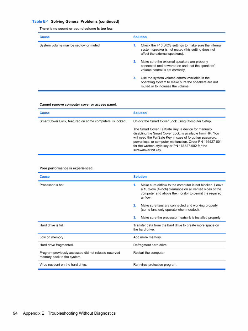
There is no sound or sound volume is too low.
Cause Solution
System volume may be set low or muted. 1. Check the F10 BIOS settings to make sure the internalsystem speaker is not muted (this setting does notaffect the external speakers).
2. Make sure the external speakers are properlyconnected and powered on and that the speakers'volume control is set correctly.
3. Use the system volume control available in theoperating system to make sure the speakers are notmuted or to increase the volume.
Cannot remove computer cover or access panel.
Cause Solution
Smart Cover Lock, featured on some computers, is locked. Unlock the Smart Cover Lock using Computer Setup.
The Smart Cover FailSafe Key, a device for manuallydisabling the Smart Cover Lock, is available from HP. Youwill need the FailSafe Key in case of forgotten password,power loss, or computer malfunction. Order PN 166527-001for the wrench-style key or PN 166527-002 for thescrewdriver bit key.
Poor performance is experienced.
Cause Solution
Processor is hot. 1. Make sure airflow to the computer is not blocked. Leavea 10.2-cm (4-inch) clearance on all vented sides of thecomputer and above the monitor to permit the requiredairflow.
2. Make sure fans are connected and working properly(some fans only operate when needed).
3. Make sure the processor heatsink is installed properly.
Hard drive is full. Transfer data from the hard drive to create more space onthe hard drive.
Low on memory. Add more memory.
Hard drive fragmented. Defragment hard drive.
Program previously accessed did not release reservedmemory back to the system.
Restart the computer.
Virus resident on the hard drive. Run virus protection program.
Table E-1 Solving General Problems (continued)
94 Appendix E Troubleshooting Without Diagnostics

Poor performance is experienced.
Cause Solution
Too many applications running. 1. Close unnecessary applications to free up memory.
2. Add more memory. Some applications run in thebackground and can be closed by right-clicking on theircorresponding icons in the task tray. To prevent theseapplications from launching at startup, go to Start >Run (Windows XP) or Start > All Programs >Accessories > Run (Windows Vista and Windows 7)and type msconfig. On the Startup tab of the SystemConfiguration Utility, clear applications that you do notwant to launch automatically.
Some software applications, especially games, are stressfulon the graphics subsystem
1. Lower the display resolution for the current applicationor consult the documentation that came with theapplication for suggestions on how to improveperformance by adjusting parameters in the application.
2. Add more memory.
3. Upgrade the graphics solution.
Cause unknown. Restart the computer.
Computer powered off automatically and the Power LED flashes Red two times, once every second, followed by atwo second pause, and the computer beeps two times. (Beeps stop after fifth iteration but LEDs continue flashing).
Cause Solution
Processor thermal protection activated:
A fan may be blocked or not turning.
OR
The heatsink is not properly attached to the processor.
1. Ensure that the computer air vents are not blocked andthe processor cooling fan is running.
2. Open hood, press power button, and see if theprocessor fan spins. If the processor fan is not spinning,make sure the fan's cable is plugged onto the systemboard header.
3. If fan is plugged in, but is not spinning, then replace theheatsink/fan assembly.
4. Contact an authorized reseller or service provider.
Table E-1 Solving General Problems (continued)
Solving General Problems 95

System does not power on and the LEDs on the front of the computer are not flashing.
Cause Solution
System unable to power on. Press and hold the power button for less than 4 seconds. Ifthe hard drive LED turns green, then:
1. Check that the voltage selector, located on the rear ofthe power supply on some models, is set to theappropriate voltage. Proper voltage setting depends onyour region.
2. Remove the expansion cards one at a time until the5V_aux light on the system board turns on.
3. Replace the system board.
OR
Press and hold the power button for less than 4 seconds. Ifthe hard drive LED does not turn on green then:
1. Check that the unit is plugged into a working AC outlet.
2. Open hood and check that the power button harness isproperly connected to the system board.
3. Check that both power supply cables are properlyconnected to the system board.
4. Check to see if the 5V_aux light on the system board isturned on. If it is turned on, then replace the powerbutton harness.
5. If the 5V_aux light on the system board is off, thenreplace the power supply.
6. Replace the system board.
Table E-1 Solving General Problems (continued)
96 Appendix E Troubleshooting Without Diagnostics

Solving Power ProblemsCommon causes and solutions for power problems are listed in the following table.
Table E-2 Solving Power Problems
Power supply shuts down intermittently.
Cause Solution
Voltage selector switch on rear of computer chassis (somemodels) not switched to correct line voltage (115V or 230V).
Select the proper AC voltage using the selector switch.
Power supply will not turn on because of internal powersupply fault.
Contact an authorized service provider to replace the powersupply.
Computer powered off automatically and the Power LED flashes Red two times, once every second, followed by atwo second pause, and the computer beeps two times. (Beeps stop after fifth iteration but LEDs continue flashing.)
Cause Solution
Processor thermal protection activated:
A fan may be blocked or not turning.
OR
The heatsink is not properly attached to the processor.
1. Ensure that the computer air vents are not blocked andthe processor cooling fan is running.
2. Open hood, press power button, and see if theprocessor fan spins. If the processor fan is not spinning,make sure the fan's cable is plugged onto the systemboard header.
3. If fan is plugged in, but is not spinning, then replace theheatsink/fan assembly.
4. Contact an authorized reseller or service provider.
Power LED flashes Red four times, once every second, followed by a two second pause, and the computer beepsfour times. (Beeps stop after fifth iteration but LEDs continue flashing.)
Cause Solution
The incorrect external power supply adapter is being used onthe USDT.
The USDT power supply adapter must be at 135W and usethe Smart ID technology before the system will power up.Replace the power supply adapter with the HP-suppliedUSDT power supply adapter.
Solving Power Problems 97

Solving Diskette ProblemsCommon causes and solutions for diskette problems are listed in the following table.
NOTE: The computer does not support internal diskette drives. Only USB diskette drives aresupported.
NOTE: You may need to reconfigure the computer when you add or remove hardware, such as anadditional diskette drive. See Solving Hardware Installation Problems on page 116 for instructions.
Table E-3 Solving Diskette Problems
Diskette drive light stays on.
Cause Solution
Diskette is damaged. In Microsoft Windows XP, right-click Start, click Explore,and select a drive. Select File > Properties > Tools. UnderError-checking click Check Now.
In Microsoft Windows Vista and Windows 7, right-click Start,click Explore, and right-click on a drive. SelectProperties then select the Tools tab. Under Error-checkingclick Check Now.
Diskette is incorrectly inserted. Remove diskette and reinsert.
Drive cable is not properly connected. Reconnect drive cable. Ensure that all four pins on thediskette power cable are connected to the drive.
Drive not found.
Cause Solution
Cable is loose. Reseat diskette drive data and power cable.
Removable drive is not seated properly. Reseat the drive.
Diskette drive cannot write to a diskette.
Cause Solution
Diskette is not formatted. Format the diskette.
1. From Windows Explorer select the disk (A) drive.
2. Right-click the drive letter and select Format.
3. Select the desired options, and click Start to beginformatting the diskette.
Diskette is write-protected. Use another diskette or remove the write protection.
Writing to the wrong drive. Check the drive letter in the path statement.
Not enough space is left on the diskette. 1. Use another diskette.
2. Delete unneeded files from diskette.
Diskette is damaged. Replace the damaged disk.
98 Appendix E Troubleshooting Without Diagnostics
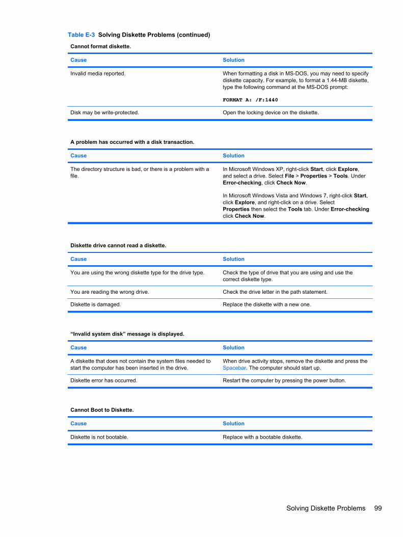
Cannot format diskette.
Cause Solution
Invalid media reported. When formatting a disk in MS-DOS, you may need to specifydiskette capacity. For example, to format a 1.44-MB diskette,type the following command at the MS-DOS prompt:
FORMAT A: /F:1440
Disk may be write-protected. Open the locking device on the diskette.
A problem has occurred with a disk transaction.
Cause Solution
The directory structure is bad, or there is a problem with afile.
In Microsoft Windows XP, right-click Start, click Explore,and select a drive. Select File > Properties > Tools. UnderError-checking, click Check Now.
In Microsoft Windows Vista and Windows 7, right-click Start,click Explore, and right-click on a drive. SelectProperties then select the Tools tab. Under Error-checkingclick Check Now.
Diskette drive cannot read a diskette.
Cause Solution
You are using the wrong diskette type for the drive type. Check the type of drive that you are using and use thecorrect diskette type.
You are reading the wrong drive. Check the drive letter in the path statement.
Diskette is damaged. Replace the diskette with a new one.
“Invalid system disk” message is displayed.
Cause Solution
A diskette that does not contain the system files needed tostart the computer has been inserted in the drive.
When drive activity stops, remove the diskette and press theSpacebar. The computer should start up.
Diskette error has occurred. Restart the computer by pressing the power button.
Cannot Boot to Diskette.
Cause Solution
Diskette is not bootable. Replace with a bootable diskette.
Table E-3 Solving Diskette Problems (continued)
Solving Diskette Problems 99
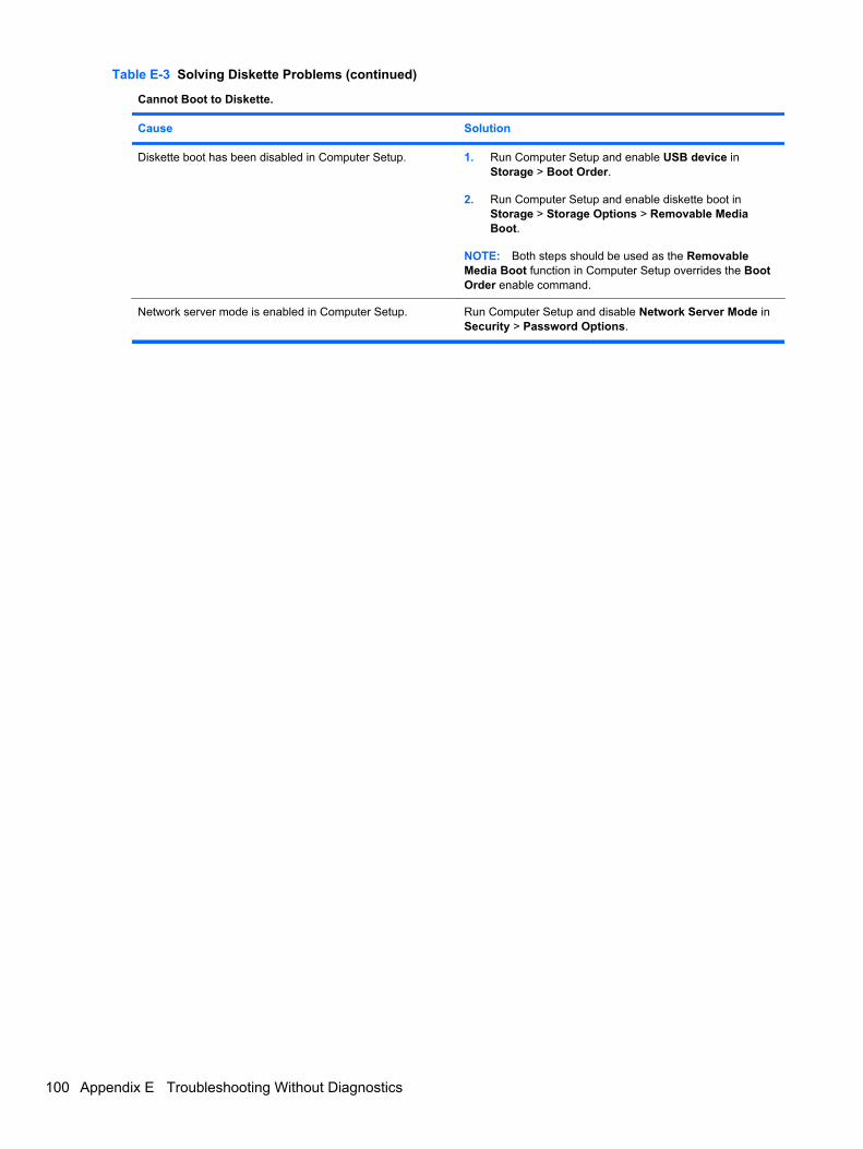
Cannot Boot to Diskette.
Cause Solution
Diskette boot has been disabled in Computer Setup. 1. Run Computer Setup and enable USB device inStorage > Boot Order.
2. Run Computer Setup and enable diskette boot inStorage > Storage Options > Removable MediaBoot.
NOTE: Both steps should be used as the RemovableMedia Boot function in Computer Setup overrides the BootOrder enable command.
Network server mode is enabled in Computer Setup. Run Computer Setup and disable Network Server Mode inSecurity > Password Options.
Table E-3 Solving Diskette Problems (continued)
100 Appendix E Troubleshooting Without Diagnostics
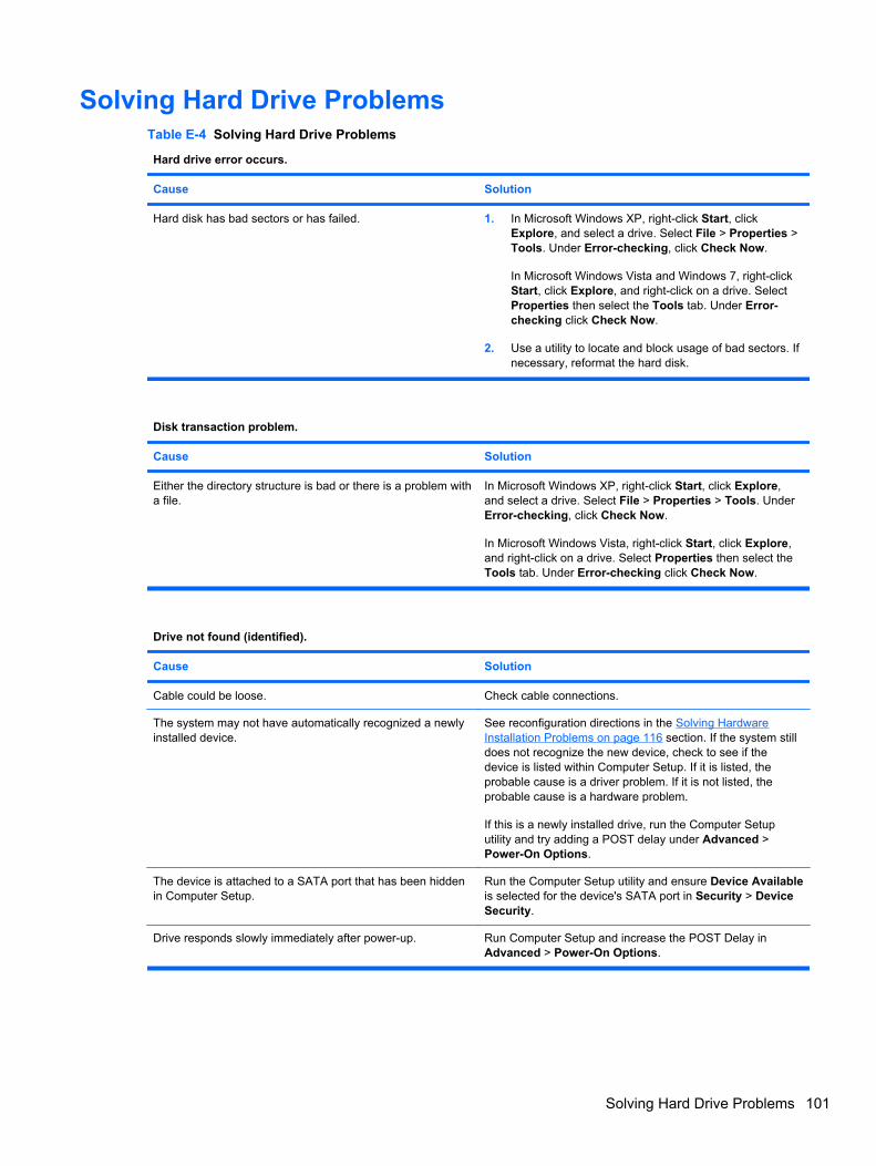
Solving Hard Drive ProblemsTable E-4 Solving Hard Drive Problems
Hard drive error occurs.
Cause Solution
Hard disk has bad sectors or has failed. 1. In Microsoft Windows XP, right-click Start, clickExplore, and select a drive. Select File > Properties >Tools. Under Error-checking, click Check Now.
In Microsoft Windows Vista and Windows 7, right-clickStart, click Explore, and right-click on a drive. SelectProperties then select the Tools tab. Under Error-checking click Check Now.
2. Use a utility to locate and block usage of bad sectors. Ifnecessary, reformat the hard disk.
Disk transaction problem.
Cause Solution
Either the directory structure is bad or there is a problem witha file.
In Microsoft Windows XP, right-click Start, click Explore,and select a drive. Select File > Properties > Tools. UnderError-checking, click Check Now.
In Microsoft Windows Vista, right-click Start, click Explore,and right-click on a drive. Select Properties then select theTools tab. Under Error-checking click Check Now.
Drive not found (identified).
Cause Solution
Cable could be loose. Check cable connections.
The system may not have automatically recognized a newlyinstalled device.
See reconfiguration directions in the Solving HardwareInstallation Problems on page 116 section. If the system stilldoes not recognize the new device, check to see if thedevice is listed within Computer Setup. If it is listed, theprobable cause is a driver problem. If it is not listed, theprobable cause is a hardware problem.
If this is a newly installed drive, run the Computer Setuputility and try adding a POST delay under Advanced >Power-On Options.
The device is attached to a SATA port that has been hiddenin Computer Setup.
Run the Computer Setup utility and ensure Device Availableis selected for the device's SATA port in Security > DeviceSecurity.
Drive responds slowly immediately after power-up. Run Computer Setup and increase the POST Delay inAdvanced > Power-On Options.
Solving Hard Drive Problems 101

Nonsystem disk/NTLDR missing message.
Cause Solution
The system is trying to start from a diskette that is notbootable.
Remove the diskette from the diskette drive.
The system is trying to start from the hard drive but the harddrive may have been damaged.
1. Insert a bootable diskette into the diskette drive andrestart the computer.
2. Check the hard drive format using fdisk: If NTFSformatting, use a third party reader to evaluate thedrive. If FAT32 formatting, the hard drive cannot beaccessed.
System files missing or not properly installed. 1. Insert a bootable diskette into the diskette drive andrestart the computer.
2. Check the hard drive format using Fdisk: If NFTFSformatting, use a third party reader to evaluate thedrive. If FAT32 formatting, the hard drive cannot beaccessed.
3. Install system files for the appropriate operating system.
Hard drive boot has been disabled in Computer Setup. Run the Computer Setup utility and enable the hard driveentry in the Storage > Boot Order list.
Bootable hard drive is not attached as first in a multi-harddrive configuration.
If attempting to boot from a hard drive, ensure it is attachedto dark blue SATA connector on the system board.
Bootable hard drive's controller is not listed first in the BootOrder.
Run the Computer Setup utility and select Storage > BootOrder and ensure the bootable hard drive's controller islisted immediately under the Hard Drive entry.
Computer will not boot from hard drive.
Cause Solution
The device is attached to a SATA port that has been hiddenin Computer Setup.
Run the Computer Setup utility and ensure Device Availableis selected for the device's SATA port in Security > DeviceSecurity.
Boot order is not correct. Run the Computer Setup utility and change boot sequence inStorage > Boot Order.
Hard Drive's “Emulation Type” is set to “None.” Run the Computer Setup utility and change the “EmulationType” to “Hard Disk” in the device's details under Storage >Device Configuration.
Hard drive is damaged. Observe if the front panel Power LED is blinking RED and ifany beeps are heard. See Appendix A, POST ErrorMessages on page 135 to determine possible causes for theblinking red and beep codes.
See the Worldwide Limited Warranty for terms andconditions.
Table E-4 Solving Hard Drive Problems (continued)
102 Appendix E Troubleshooting Without Diagnostics

Computer seems to be locked up.
Cause Solution
Program in use has stopped responding to commands. Attempt the normal Windows “Shut Down” procedure. If thisfails, press the power button for four or more seconds to turnoff the power. To restart the computer, press the powerbutton again.
The removable hard drive has no power to the hard drive enclosure.
Cause Solution
The lock on the enclosure is not turned to the “ON” position. Insert the key and turn the lock clockwise 90 degrees. Thegreen LED on the front of the enclosure should be on.
Power cable from the computer power supply to theenclosure frame is not properly connected.
Check the power supply to make sure it is properlyconnected to the rear of the enclosure frame.
The removable hard drive is not recognized by the computer.
Cause Solution
The removable hard drive carrier is not fully seated in theenclosure frame or the hard drive is not fully seated in thecarrier.
Push the carrier into the enclosure frame so that theconnector on the rear of the frame is properly seated. If thisdoes not solve the problem, turn off the computer, removethe carrier, and check to see if the connector on the harddrive is properly seated in the carrier.
The removable hard drive enclosure is beeping and the green LED is flashing.
Cause Solution
Fan failure alarm on the removable hard drive enclosure hasbeen activated.
Shut down the computer and contact HP for a replacementenclosure.
Table E-4 Solving Hard Drive Problems (continued)
Solving Hard Drive Problems 103

Solving Media Card Reader ProblemsTable E-5 Solving Media Card Reader Problems
Media card will not work in a digital camera after formatting it in Microsoft Windows XP or Microsoft Windows Vista.
Cause Solution
By default, Windows XP and Windows Vista will format anymedia card with a capacity greater than 32MB with theFAT32 format. Most digital cameras use the FAT (FAT16 &FAT12) format and can not operate with a FAT32 formattedcard.
Either format the media card in the digital camera or selectFAT file system to format the media card in a computer withWindows XP or Windows Vista.
A write-protected or locked error occurs when attempting to write to the media card.
Cause Solution
Media card is locked. Locking the media card is a safetyfeature that prevents writing to and deleting from an SD/Memory Stick/PRO card.
If using an SD card, make sure that the lock tab located onthe right of the SD card is not in the locked position. If usinga Memory Stick/PRO card, make sure that the lock tablocated on the bottom of the Memory Stick/PRO card is notin the locked position.
Can not write to the media card.
Cause Solution
The media card is a read-only memory (ROM) card. Check the manufacturer’s documentation included with yourcard to see if it writable. Refer to the previous section for alist of compatible cards.
Media card is locked. Locking the media card is a safetyfeature that prevents writing to and deleting from an SD/Memory Stick/PRO card.
If using an SD card, make sure that the lock tab located onthe right of the SD card is not in the locked position. If usinga Memory Stick/PRO card, make sure that the lock tablocated on the bottom of the Memory Stick/PRO card is notin the locked position.
Unable to access data on the media card after inserting it into a slot.
Cause Solution
The media card is not inserted properly, is inserted in thewrong slot, or is not supported.
Ensure that the card is inserted properly with the goldcontact on the correct side. The green LED will light ifinserted properly.
104 Appendix E Troubleshooting Without Diagnostics

Do not know how to remove a media card correctly.
Cause Solution
The computer’s software is used to safely eject the card. Open My Computer (Windows XP) or Computer (WindowsVista and Windows 7), right-click on the corresponding driveicon, and select Eject. Then pull the card out of the slot.
NOTE: Never remove the card when the green LED isflashing
After installing the media card reader and booting to Windows, the reader and the inserted cards are not recognizedby the computer.
Cause Solution
The operating system needs time to recognize the device ifthe reader was just installed into the computer and you areturning the PC on for the first time.
Wait a few seconds so that the operating system canrecognize the reader and the available ports, and thenrecognize whatever media is inserted in the reader.
After inserting a media card in the reader, the computer attempts to boot from the media card.
Cause Solution
The inserted media card has boot capability. If you do not want to boot from the media card, remove itduring boot or do not select the option to boot from theinserted media card during the boot process.
Table E-5 Solving Media Card Reader Problems (continued)
Solving Media Card Reader Problems 105
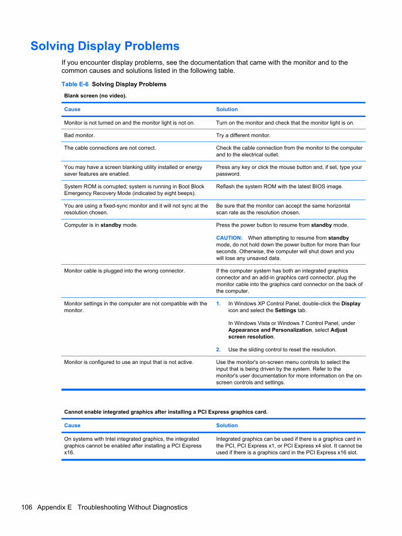
Solving Display ProblemsIf you encounter display problems, see the documentation that came with the monitor and to thecommon causes and solutions listed in the following table.
Table E-6 Solving Display Problems
Blank screen (no video).
Cause Solution
Monitor is not turned on and the monitor light is not on. Turn on the monitor and check that the monitor light is on.
Bad monitor. Try a different monitor.
The cable connections are not correct. Check the cable connection from the monitor to the computerand to the electrical outlet.
You may have a screen blanking utility installed or energysaver features are enabled.
Press any key or click the mouse button and, if set, type yourpassword.
System ROM is corrupted; system is running in Boot BlockEmergency Recovery Mode (indicated by eight beeps).
Reflash the system ROM with the latest BIOS image.
You are using a fixed-sync monitor and it will not sync at theresolution chosen.
Be sure that the monitor can accept the same horizontalscan rate as the resolution chosen.
Computer is in standby mode. Press the power button to resume from standby mode.
CAUTION: When attempting to resume from standbymode, do not hold down the power button for more than fourseconds. Otherwise, the computer will shut down and youwill lose any unsaved data.
Monitor cable is plugged into the wrong connector. If the computer system has both an integrated graphicsconnector and an add-in graphics card connector, plug themonitor cable into the graphics card connector on the back ofthe computer.
Monitor settings in the computer are not compatible with themonitor.
1. In Windows XP Control Panel, double-click the Displayicon and select the Settings tab.
In Windows Vista or Windows 7 Control Panel, underAppearance and Personalization, select Adjustscreen resolution.
2. Use the sliding control to reset the resolution.
Monitor is configured to use an input that is not active. Use the monitor's on-screen menu controls to select theinput that is being driven by the system. Refer to themonitor's user documentation for more information on the on-screen controls and settings.
Cannot enable integrated graphics after installing a PCI Express graphics card.
Cause Solution
On systems with Intel integrated graphics, the integratedgraphics cannot be enabled after installing a PCI Expressx16.
Integrated graphics can be used if there is a graphics card inthe PCI, PCI Express x1, or PCI Express x4 slot. It cannot beused if there is a graphics card in the PCI Express x16 slot.
106 Appendix E Troubleshooting Without Diagnostics
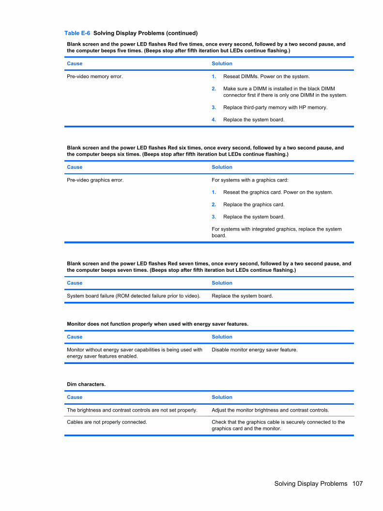
Blank screen and the power LED flashes Red five times, once every second, followed by a two second pause, andthe computer beeps five times. (Beeps stop after fifth iteration but LEDs continue flashing.)
Cause Solution
Pre-video memory error. 1. Reseat DIMMs. Power on the system.
2. Make sure a DIMM is installed in the black DIMMconnector first if there is only one DIMM in the system.
3. Replace third-party memory with HP memory.
4. Replace the system board.
Blank screen and the power LED flashes Red six times, once every second, followed by a two second pause, andthe computer beeps six times. (Beeps stop after fifth iteration but LEDs continue flashing.)
Cause Solution
Pre-video graphics error. For systems with a graphics card:
1. Reseat the graphics card. Power on the system.
2. Replace the graphics card.
3. Replace the system board.
For systems with integrated graphics, replace the systemboard.
Blank screen and the power LED flashes Red seven times, once every second, followed by a two second pause, andthe computer beeps seven times. (Beeps stop after fifth iteration but LEDs continue flashing.)
Cause Solution
System board failure (ROM detected failure prior to video). Replace the system board.
Monitor does not function properly when used with energy saver features.
Cause Solution
Monitor without energy saver capabilities is being used withenergy saver features enabled.
Disable monitor energy saver feature.
Dim characters.
Cause Solution
The brightness and contrast controls are not set properly. Adjust the monitor brightness and contrast controls.
Cables are not properly connected. Check that the graphics cable is securely connected to thegraphics card and the monitor.
Table E-6 Solving Display Problems (continued)
Solving Display Problems 107

Blurry video or requested resolution cannot be set.
Cause Solution
If the graphics controller was upgraded, the correct graphicsdrivers may not be loaded.
Install the video drivers included in the upgrade kit.
Monitor is not capable of displaying requested resolution. Change requested resolution.
Graphics card is bad. Replace the graphics card.
The picture is broken up, rolls, jitters, or flashes.
Cause Solution
The monitor connections may be incomplete or the monitormay be incorrectly adjusted.
1. Be sure the monitor cable is securely connected to thecomputer.
2. In a two-monitor system or if another monitor is in closeproximity, be sure the monitors are not interfering witheach other’s electromagnetic field by moving themapart.
3. Fluorescent lights or fans may be too close to themonitor.
Monitor needs to be degaussed. Degauss the monitor. Refer to the documentation that camewith the monitor for instructions.
Image is not centered.
Cause Solution
Position may need adjustment. Press the monitor's Menu button to access the OSD menu.Select ImageControl/ Horizontal Position or VerticalPosition to adjust the horizontal or vertical position of theimage.
“No Connection, Check Signal Cable” displays on screen.
Cause Solution
Monitor video cable is disconnected. Connect the video cable between the monitor and computer.
CAUTION: Ensure that the computer power is off whileconnecting the video cable.
“Out of Range” displays on screen.
Cause Solution
Video resolution and refresh rate are set higher than whatthe monitor supports.
Restart the computer and enter Safe Mode. Change thesettings to a supported setting then restart the computer sothat the new settings take effect.
Table E-6 Solving Display Problems (continued)
108 Appendix E Troubleshooting Without Diagnostics

Vibrating or rattling noise coming from inside a CRT monitor when powered on.
Cause Solution
Monitor degaussing coil has been activated. None. It is normal for the degaussing coil to be activatedwhen the monitor is powered on.
Clicking noise coming from inside a CRT monitor.
Cause Solution
Electronic relays have been activated inside the monitor. None. It is normal for some monitors to make a clicking noisewhen turned on and off, when going in and out of standbymode, and when changing resolutions.
High pitched noise coming from inside a flat panel monitor.
Cause Solution
Brightness and/or contrast settings are too high. Lower brightness and/or contrast settings.
Fuzzy focus; streaking, ghosting, or shadowing effects; horizontal scrolling lines; faint vertical bars; or unable tocenter the picture on the screen (flat panel monitors using an analog VGA input connection only).
Cause Solution
Flat panel monitor’s internal digital conversion circuits maybe unable to correctly interpret the output synchronization ofthe graphics card.
1. Select the monitor’s Auto-Adjustment option in themonitor’s on-screen display menu.
2. Manually synchronize the Clock and Clock Phase on-screen display functions. To download a SoftPaq thatwill assist you with the synchronization, go to thefollowing Web site, select the appropriate monitor, anddownload either SP32347 or SP32202:http://www.hp.com/support
Graphics card is not seated properly or is bad. 1. Reseat the graphics card.
2. Replace the graphics card.
Certain typed symbols do not appear correct.
Cause Solution
The font you are using does not support that particularsymbol.
Use the Character Map to locate and select the appropriatesymbol. Click Start > All Programs > Accessories >System Tools > Character Map. You can copy the symbolfrom the Character Map into a document.
Table E-6 Solving Display Problems (continued)
Solving Display Problems 109

Solving Audio ProblemsIf the computer has audio features and you encounter audio problems, see the common causes andsolutions listed in the following table.
Table E-7 Solving Audio Problems
Sound cuts in and out.
Cause Solution
Processor resources are being used by other openapplications.
Shut down all open processor-intensive applications.
Direct sound latency, common in many media playerapplications.
In Windows XP only:
1. From the Control Panel, select Sounds and AudioDevices.
2. On the Audio tab, select a device from the SoundPlayback list.
3. Click the Advanced button and select the Performancetab.
4. Set the Hardware acceleration slider to None and theSample rate conversion quality slider to Good andretest the audio.
5. Set the Hardware acceleration slider to Full and theSample rate conversion quality slider to Best andretest the audio.
Sound does not come out of the speaker or headphones.
Cause Solution
Software volume control is turned down or muted. Double-click the Speaker icon on the taskbar, then makesure that Mute is not selected and use the volume slider toadjust the volume.
Audio is hidden in Computer Setup. Enable the audio in Computer Setup: Security >Device Security > System Audio.
The external speakers are not turned on. Turn on the external speakers.
The audio device may be connected to the wrong jack. Ensure that the device is connected to the correct jack on thecomputer. The speakers should be plugged into the rear line-out jack and the headphones should be plugged into thefront headphone jack.
External speakers plugged into the wrong audio jack on arecently installed sound card.
See the sound card documentation for proper speakerconnection.
Digital CD audio is not enabled. Enable digital CD audio. In the Device Manager, right-clickon the CD/DVD device and select Properties. Make sureEnable digital CD audio for this CD-ROM device ischecked.
Headphones or devices connected to the line-out connectormute the internal speaker.
Turn on and use headphones or external speakers, ifconnected, or disconnect headphones or external speakers.
110 Appendix E Troubleshooting Without Diagnostics

Sound does not come out of the speaker or headphones.
Cause Solution
Computer is in standby mode. Press the power button to resume from standby mode.
CAUTION: When attempting to resume from standbymode, do not hold down the power button for more than fourseconds. Otherwise, the computer will shut down and youwill lose any unsaved data.
Internal speaker is disabled in Computer Setup. Enable the internal speaker in Computer Setup. SelectAdvanced > Device Options > Internal Speaker.
The application is set to use a different audio device thanspeakers.
Some graphics cards support audio over the DisplayPortconnection, so multiple audio devices may be listed inDevice Manager. Make sure the correct device is beingused.
Some applications can select which audio output device isused.
Make sure the application has selected the correct audiodevice.
The operating system controls may be set to use a differentaudio device as the default output device than what isexpected.
Set the operating system to use the correct audio device.
Sound from headphones is not clear or muffled.
Cause Solution
Headphones are plugged into the rear audio outputconnector. The rear audio output connector is for poweredaudio devices and is not designed for headphone use.
Plug the headphones into the headphone connector on thefront of the computer.
Computer appears to be locked up while recording audio.
Cause Solution
The hard disk may be full. Before recording, make sure there is enough free space onthe hard disk. You can also try recording the audio file in acompressed format.
Line-in jack is not functioning properly.
Cause Solution
Jack has been reconfigured in the audio driver or applicationsoftware.
In the audio driver or application software, reconfigure thejack or set the jack to its default value.
Table E-7 Solving Audio Problems (continued)
Solving Audio Problems 111

There is no sound or sound volume is too low.
Cause Solution
The application is set to use a different audio device thanspeakers.
Some graphics cards support audio over the DisplayPortconnection, so multiple audio devices may be listed inDevice Manager. Make sure the correct device is beingused.
Some applications can select which audio output device isused.
Make sure the application has selected the correct audiodevice.
The operating system controls may be set to use a differentaudio device as the default output device than what isexpected.
Set the operating system to use the correct audio device.
Table E-7 Solving Audio Problems (continued)
112 Appendix E Troubleshooting Without Diagnostics

Solving Printer ProblemsIf you encounter printer problems, see the documentation that came with the printer and to thecommon causes and solutions listed in the following table.
Table E-8 Solving Printer Problems
Printer will not print.
Cause Solution
Printer is not turned on and online. Turn the printer on and make sure it is online.
The correct printer drivers for the application are notinstalled.
1. Install the correct printer driver for the application.
2. Try printing using the MS-DOS command:
DIR C:\ > [printer port]
where [printer port] is the address of the printer beingused. If the printer works, reload the printer driver.
If you are on a network, you may not have made theconnection to the printer.
Make the proper network connections to the printer.
Printer may have failed. Run printer self-test.
Printer will not turn on.
Cause Solution
The cables may not be connected properly. Reconnect all cables and check the power cord andelectrical outlet.
Printer prints garbled information.
Cause Solution
The correct printer driver for the application is not installed. Install the correct printer driver for the application.
The cables may not be connected properly. Reconnect all cables.
Printer memory may be overloaded. Reset the printer by turning it off for one minute, then turn itback on.
Printer is offline.
Cause Solution
The printer may be out of paper. Check the paper tray and refill it if it is empty. Select online.
Solving Printer Problems 113

Solving Keyboard and Mouse ProblemsIf you encounter keyboard or mouse problems, see the documentation that came with the equipmentand to the common causes and solutions listed in the following table.
Table E-9 Solving Keyboard Problems
Keyboard commands and typing are not recognized by the computer.
Cause Solution
Keyboard connector is not properly connected. 1. On the Windows XP or Windows 7 Desktop, click Start> Shut Down.
On the Windows Vista Desktop, click Start, click thearrow on the lower right corner of the Start menu, thenselect Shut Down.
2. After the shutdown is complete, reconnect the keyboardto the back of the computer and restart the computer.
Program in use has stopped responding to commands. Shut down your computer using the mouse and then restartthe computer.
Keyboard needs repairs. See the Worldwide Limited Warranty for terms andconditions.
Computer is in standby mode. Press the power button to resume from standby mode.
CAUTION: When attempting to resume from standbymode, do not hold down the power button for more than fourseconds. Otherwise, the computer will shut down and youwill lose any unsaved data.
Cursor will not move using the arrow keys on the keypad.
Cause Solution
The Num Lock key may be on. Press the Num Lock key. The Num Lock light should not beon if you want to use the arrow keys. The Num Lock key canbe disabled (or enabled) in Computer Setup.
Table E-10 Solving Mouse Problems
Mouse does not respond to movement or is too slow.
Cause Solution
Mouse connector is not properly plugged into the back of thecomputer.
Shut down the computer using the keyboard.
1. Press the Ctrl and Esc keys at the same time (or pressthe Windows logo key) to display the Start menu.
2. Use the arrow keys to select Shut Down and thenpress the Enter key.
3. After the shutdown is complete, plug the mouseconnector into the back of the computer (or thekeyboard) and restart.
Program in use has stopped responding to commands. Shut down the computer using the keyboard then restart thecomputer.
114 Appendix E Troubleshooting Without Diagnostics

Mouse does not respond to movement or is too slow.
Cause Solution
Mouse may need cleaning. Remove the roller ball cover on the mouse and clean theinternal components.
Mouse may need repair. See the Worldwide Limited Warranty for terms andconditions.
Computer is in standby mode. Press the power button to resume from standby mode.
CAUTION: When attempting to resume from standbymode, do not hold down the power button for more than fourseconds. Otherwise, the computer will shut down and youwill lose any unsaved data.
Mouse will only move vertically, horizontally, or movement is jerky.
Cause Solution
Mouse roller ball or the rotating encoder shafts that makecontact with the ball are dirty.
Remove roller ball cover from the bottom of the mouse andclean the internal components with a mouse cleaning kitavailable from most computer stores.
Table E-10 Solving Mouse Problems (continued)
Solving Keyboard and Mouse Problems 115

Solving Hardware Installation ProblemsYou may need to reconfigure the computer when you add or remove hardware, such as an additionaldrive or expansion card. If you install a plug and play device, Windows automatically recognizes thedevice and configures the computer. If you install a non–plug and play device, you must reconfigurethe computer after completing installation of the new hardware. In Windows, use the Add HardwareWizard and follow the instructions that appear on the screen.
WARNING! When the computer is plugged into an AC power source, voltage is always applied tothe system board. To reduce the risk of personal injury from electrical shock and/or hot surfaces, besure to disconnect the power cord from the wall outlet and allow the internal system components tocool before touching.
Table E-11 Solving Hardware Installation Problems
A new device is not recognized as part of the system.
Cause Solution
Device is not seated or connected properly. Ensure that the device is properly and securely connectedand that pins in the connector are not bent down.
Cable(s) of new external device are loose or power cablesare unplugged.
Ensure that all cables are properly and securely connectedand that pins in the cable or connector are not bent down.
Power switch of new external device is not turned on. Turn off the computer, turn on the external device, then turnon the computer to integrate the device with the computersystem.
When the system advised you of changes to theconfiguration, you did not accept them.
Reboot the computer and follow the instructions foraccepting the changes.
A plug and play board may not automatically configure whenadded if the default configuration conflicts with other devices.
Use Windows Device Manager to deselect the automaticsettings for the board and choose a basic configuration thatdoes not cause a resource conflict. You can also useComputer Setup to reconfigure or disable devices to resolvethe resource conflict.
USB ports on the computer are disabled in Computer Setup. Run the Computer Setup utility and ensure that Enable isselected for the appropriate USB ports under Security >USB Security.
Computer will not start.
Cause Solution
Wrong memory modules were used in the upgrade ormemory modules were installed in the wrong location.
1. Review the documentation that came with the system todetermine if you are using the correct memory modulesand to verify the proper installation.
NOTE: SODIMM1 must always be installed.
2. Observe the beeps and LED lights on the front of thecomputer. Beeps and flashing LEDs are codes forspecific problems.
3. If you still cannot resolve the issue, contact CustomerSupport.
116 Appendix E Troubleshooting Without Diagnostics
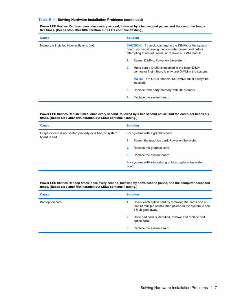
Power LED flashes Red five times, once every second, followed by a two second pause, and the computer beepsfive times. (Beeps stop after fifth iteration but LEDs continue flashing.)
Cause Solution
Memory is installed incorrectly or is bad. CAUTION: To avoid damage to the DIMMs or the systemboard, you must unplug the computer power cord beforeattempting to reseat, install, or remove a DIMM module.
1. Reseat DIMMs. Power on the system.
2. Make sure a DIMM is installed in the black DIMMconnector first if there is only one DIMM in the system.
NOTE: On USDT models, SODIMM1 must always beinstalled.
3. Replace third-party memory with HP memory.
4. Replace the system board.
Power LED flashes Red six times, once every second, followed by a two second pause, and the computer beeps sixtimes. (Beeps stop after fifth iteration but LEDs continue flashing.)
Cause Solution
Graphics card is not seated properly or is bad, or systemboard is bad.
For systems with a graphics card:
1. Reseat the graphics card. Power on the system.
2. Replace the graphics card.
3. Replace the system board.
For systems with integrated graphics, replace the systemboard.
Power LED flashes Red ten times, once every second, followed by a two second pause, and the computer beeps tentimes. (Beeps stop after fifth iteration but LEDs continue flashing.)
Cause Solution
Bad option card. 1. Check each option card by removing the cards one attime (if multiple cards), then power on the system to seeif fault goes away.
2. Once bad card is identified, remove and replace badoption card.
3. Replace the system board.
Table E-11 Solving Hardware Installation Problems (continued)
Solving Hardware Installation Problems 117
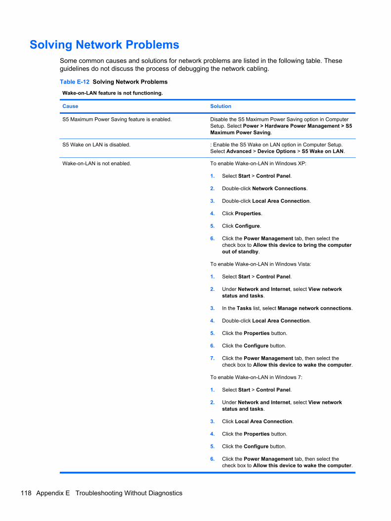
Solving Network ProblemsSome common causes and solutions for network problems are listed in the following table. Theseguidelines do not discuss the process of debugging the network cabling.
Table E-12 Solving Network Problems
Wake-on-LAN feature is not functioning.
Cause Solution
S5 Maximum Power Saving feature is enabled. Disable the S5 Maximum Power Saving option in ComputerSetup. Select Power > Hardware Power Management > S5Maximum Power Saving.
S5 Wake on LAN is disabled. : Enable the S5 Wake on LAN option in Computer Setup.Select Advanced > Device Options > S5 Wake on LAN.
Wake-on-LAN is not enabled. To enable Wake-on-LAN in Windows XP:
1. Select Start > Control Panel.
2. Double-click Network Connections.
3. Double-click Local Area Connection.
4. Click Properties.
5. Click Configure.
6. Click the Power Management tab, then select thecheck box to Allow this device to bring the computerout of standby.
To enable Wake-on-LAN in Windows Vista:
1. Select Start > Control Panel.
2. Under Network and Internet, select View networkstatus and tasks.
3. In the Tasks list, select Manage network connections.
4. Double-click Local Area Connection.
5. Click the Properties button.
6. Click the Configure button.
7. Click the Power Management tab, then select thecheck box to Allow this device to wake the computer.
To enable Wake-on-LAN in Windows 7:
1. Select Start > Control Panel.
2. Under Network and Internet, select View networkstatus and tasks.
3. Click Local Area Connection.
4. Click the Properties button.
5. Click the Configure button.
6. Click the Power Management tab, then select thecheck box to Allow this device to wake the computer.
118 Appendix E Troubleshooting Without Diagnostics

Network driver does not detect network controller.
Cause Solution
Network controller is disabled. 1. Run Computer Setup and enable network controller.
2. Enable the network controller in the operating systemvia Device Manager.
Incorrect network driver. Check the network controller documentation for the correctdriver or obtain the latest driver from the manufacturer’s Website.
Network status link light never flashes.
NOTE: The network status light is supposed to flash when there is network activity.
Cause Solution
No active network is detected. Check cabling and network equipment for proper connection.
Network controller is not set up properly. Check for the device status within Windows, such as DeviceManager for driver load and the Network Connections appletwithin Windows for link status.
Network controller is disabled. 1. Run Computer Setup and enable network controller.
2. Enable the network controller in the operating systemvia Device Manager.
Network driver is not properly loaded. Reinstall network drivers.
System cannot autosense the network. Disable auto-sensing capabilities and force the system intothe correct operating mode.
Diagnostics reports a failure.
Cause Solution
The cable is not securely connected. Ensure that the cable is securely attached to the networkconnector and that the other end of the cable is securelyattached to the correct device.
The cable is attached to the incorrect connector. Ensure that the cable is attached to the correct connector.
There is a problem with the cable or a device at the otherend of the cable.
Ensure that the cable and device at the other end areoperating correctly.
Network controller interrupt is shared with an expansionboard.
Under the Computer Setup Advanced menu, change theresource settings for the board.
The network controller is defective. Contact an authorized service provider.
Table E-12 Solving Network Problems (continued)
Solving Network Problems 119

Diagnostics passes, but the computer does not communicate with the network.
Cause Solution
Network drivers are not loaded, or driver parameters do notmatch current configuration.
Make sure the network drivers are loaded and that the driverparameters match the configuration of the network controller.
Make sure the correct network client and protocol is installed.
The network controller is not configured for this computer. Select the Network icon in the Control Panel and configurethe network controller.
Network controller stopped working when an expansion board was added to the computer.
Cause Solution
Network controller interrupt is shared with an expansionboard.
Under the Computer Setup Advanced menu, change theresource settings for the board.
The network controller requires drivers. Verify that the drivers were not accidentally deleted when thedrivers for a new expansion board were installed.
The expansion board installed is a network card (NIC) andconflicts with the embedded NIC.
Under the Computer Setup Advanced menu, change theresource settings for the board.
Network controller stops working without apparent cause.
Cause Solution
The files containing the network drivers are corrupted. Reinstall the network drivers, using the Recovery Disc Setcreated from the hard drive's Recovery Partition.
The cable is not securely connected. Ensure that the cable is securely attached to the networkconnector and that the other end of the cable is securelyattached to the correct device.
The network controller is defective. Contact an authorized service provider.
New network card will not boot.
Cause Solution
New network card may be defective or may not meetindustry-standard specifications.
Install a working, industry-standard NIC, or change the bootsequence to boot from another source.
Cannot connect to network server when attempting Remote System Installation.
Cause Solution
The network controller is not configured properly. Verify Network Connectivity, that a DHCP Server is present,and that the Remote System Installation Server contains theNIC drivers for your NIC.
Table E-12 Solving Network Problems (continued)
120 Appendix E Troubleshooting Without Diagnostics

System setup utility reports unprogrammed EEPROM.
Cause Solution
Unprogrammed EEPROM. Contact an authorized service provider.
Table E-12 Solving Network Problems (continued)
Solving Network Problems 121

Solving Memory ProblemsIf you encounter memory problems, some common causes and solutions are listed in the followingtable.
CAUTION: Power may still be supplied to the DIMMs when the computer is turned off (dependingon the Management Engine (ME) settings). To avoid damage to the DIMMs or the system board, youmust unplug the computer power cord before attempting to reseat, install, or remove a DIMM module.
For those systems that support ECC memory, HP does not support mixing ECC and non-ECCmemory. Otherwise, the computer will not boot the operating system.
NOTE: The memory count will be affected by configurations with the Management Engine (ME)enabled. The ME uses 8MB of system memory in single channel mode or 16MB of memory in dual-channel mode to download, decompress, and execute the ME firmware for Out-of-Band (OOB), third-party data storage, and other management functions.
Table E-13 Solving Memory Problems
System will not boot or does not function properly after installing additional memory modules.
Cause Solution
A memory module is not installed in the XMM1 socket. Ensure that a memory module is installed in the blackSODIMM1 socket on the system board.
Memory module is not the correct type or speed grade forthe system or the new memory module is not seatedproperly.
Replace module with the correct industry-standard device forthe computer. On some models, ECC and non-ECC memorymodules cannot be mixed.
Out of memory error.
Cause Solution
Memory configuration may not be set up correctly. Use the Device Manager to check memory configuration.
You have run out of memory to run the application. Check the application documentation to determine thememory requirements.
Memory count during POST is wrong.
Cause Solution
The memory modules may not be installed correctly. Check that the memory modules have been installedcorrectly and that proper modules are used.
Integrated graphics may use system memory. No action required.
122 Appendix E Troubleshooting Without Diagnostics

Insufficient memory error during operation.
Cause Solution
Too many Terminate and Stay Resident programs (TSRs)are installed.
Delete any TSRs that you do not need.
You have run out of memory for the application. Check the memory requirements for the application or addmore memory to the computer.
Power LED flashes Red five times, once every second, followed by a two second pause, and the computer beepsfive times. (Beeps stop after fifth iteration but LEDs continue flashing.)
Cause Solution
Memory is installed incorrectly or is bad. 1. Reseat DIMMs. Power on the system.
2. Make sure a DIMM is installed in the black DIMMconnector first if there is only one DIMM in the system.
3. Replace third-party memory with HP memory.
4. Replace the system board.
Table E-13 Solving Memory Problems (continued)
Solving Memory Problems 123

Solving Processor ProblemsIf you encounter processor problems, common causes and solutions are listed in the following table.
Table E-14 Solving Processor Problems
Poor performance is experienced.
Cause Solution
Processor is hot. 1. Make sure the airflow to the computer is not blocked.
2. Make sure the fans are connected and working properly(some fans only operate when needed).
3. Make sure the processor heatsink is installed properly.
Power LED flashes Red three times, once every second, followed by a two second pause.
Cause Solution
Processor is not seated properly or not installed. 1. Check to see that the processor is present.
2. Reseat the processor.
Power LED flashes Red eleven times, once every second, followed by a two second pause.
Cause Solution
The current processor does not support a feature previouslyenabled on this system.
1. Install a TXT capable processor.
2. Disable TXT in the Computer Setup (F10) utility.
3. Reinstall the original processor.
124 Appendix E Troubleshooting Without Diagnostics

Solving CD-ROM and DVD ProblemsIf you encounter CD-ROM or DVD problems, see the common causes and solutions listed in thefollowing table or to the documentation that came with the optional device.
Table E-15 Solving CD-ROM and DVD Problems
System will not boot from CD-ROM or DVD drive.
Cause Solution
The device is attached to a SATA port that has been hiddenin the Computer Setup utility.
Run the Computer Setup utility and ensure Device Availableis selected for the device's SATA port in Security > DeviceSecurity.
Removable Media Boot is disabled in the Computer Setuputility.
Run the Computer Setup utility and enable booting toremovable media in Storage > Storage Options. EnsureCD-ROM is enabled in Storage > Boot Order.
Network Server Mode is enabled in Computer Setup. Run the Computer Setup utility and disable Network ServerMode in Security > Password Options.
Non-bootable CD in drive. Try a bootable CD in the drive.
Boot order not correct. Run the Computer Setup utility and change boot sequence inStorage > Boot Order.
Drive not found (identified).
Cause Solution
Cable could be loose. Check cable connections.
The system may not have automatically recognized a newlyinstalled device.
See reconfiguration directions in the Solving HardwareInstallation Problems on page 116 section. If the system stilldoes not recognize the new device, check to see if thedevice is listed within Computer Setup. If it is listed, theprobable cause is a driver problem. If it is not listed, theprobable cause is a hardware problem.
If this is a newly installed drive, run the Computer Setuputility and try adding a POST delay under Advanced >Power-On Options.
The device is attached to a SATA port that has been hiddenin Computer Setup.
Run the Computer Setup utility and ensure Device Availableis selected for the device's SATA port in Security > DeviceSecurity.
Drive responds slowly immediately after power-up. Run Computer Setup and increase the POST Delay inAdvanced > Power-On Options.
CD-ROM or DVD devices are not detected or driver is not loaded.
Cause Solution
Drive is not connected properly or not properly configured. See the documentation that came with the optional device.
Solving CD-ROM and DVD Problems 125
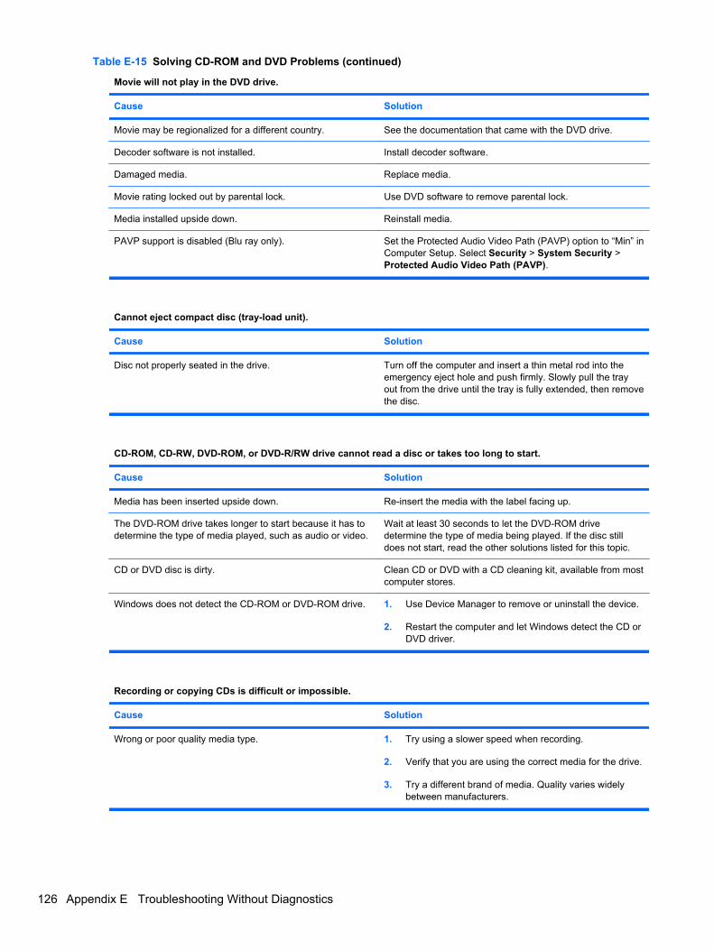
Movie will not play in the DVD drive.
Cause Solution
Movie may be regionalized for a different country. See the documentation that came with the DVD drive.
Decoder software is not installed. Install decoder software.
Damaged media. Replace media.
Movie rating locked out by parental lock. Use DVD software to remove parental lock.
Media installed upside down. Reinstall media.
PAVP support is disabled (Blu ray only). Set the Protected Audio Video Path (PAVP) option to “Min” inComputer Setup. Select Security > System Security >Protected Audio Video Path (PAVP).
Cannot eject compact disc (tray-load unit).
Cause Solution
Disc not properly seated in the drive. Turn off the computer and insert a thin metal rod into theemergency eject hole and push firmly. Slowly pull the trayout from the drive until the tray is fully extended, then removethe disc.
CD-ROM, CD-RW, DVD-ROM, or DVD-R/RW drive cannot read a disc or takes too long to start.
Cause Solution
Media has been inserted upside down. Re-insert the media with the label facing up.
The DVD-ROM drive takes longer to start because it has todetermine the type of media played, such as audio or video.
Wait at least 30 seconds to let the DVD-ROM drivedetermine the type of media being played. If the disc stilldoes not start, read the other solutions listed for this topic.
CD or DVD disc is dirty. Clean CD or DVD with a CD cleaning kit, available from mostcomputer stores.
Windows does not detect the CD-ROM or DVD-ROM drive. 1. Use Device Manager to remove or uninstall the device.
2. Restart the computer and let Windows detect the CD orDVD driver.
Recording or copying CDs is difficult or impossible.
Cause Solution
Wrong or poor quality media type. 1. Try using a slower speed when recording.
2. Verify that you are using the correct media for the drive.
3. Try a different brand of media. Quality varies widelybetween manufacturers.
Table E-15 Solving CD-ROM and DVD Problems (continued)
126 Appendix E Troubleshooting Without Diagnostics

USDT computer boots too slow after removing a CD-ROM or DVD drive.
Cause Solution
The system is searching for the drive during boot becausethe drive cable is still attached to the system board.
Disconnect the drive cable from the system board.
Solving CD-ROM and DVD Problems 127
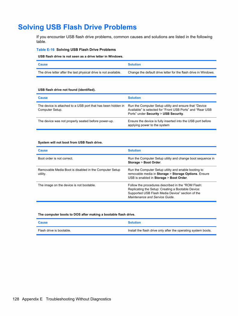
Solving USB Flash Drive ProblemsIf you encounter USB flash drive problems, common causes and solutions are listed in the followingtable.
Table E-16 Solving USB Flash Drive Problems
USB flash drive is not seen as a drive letter in Windows.
Cause Solution
The drive letter after the last physical drive is not available. Change the default drive letter for the flash drive in Windows.
USB flash drive not found (identified).
Cause Solution
The device is attached to a USB port that has been hidden inComputer Setup.
Run the Computer Setup utility and ensure that “DeviceAvailable” is selected for “Front USB Ports” and “Rear USBPorts” under Security > USB Security.
The device was not properly seated before power-up. Ensure the device is fully inserted into the USB port beforeapplying power to the system
System will not boot from USB flash drive.
Cause Solution
Boot order is not correct. Run the Computer Setup utility and change boot sequence inStorage > Boot Order.
Removable Media Boot is disabled in the Computer Setuputility.
Run the Computer Setup utility and enable booting toremovable media in Storage > Storage Options. EnsureUSB is enabled in Storage > Boot Order.
The image on the device is not bootable. Follow the procedures described in the “ROM Flash:Replicating the Setup: Creating a Bootable Device:Supported USB Flash Media Device” section of theMaintenance and Service Guide.
The computer boots to DOS after making a bootable flash drive.
Cause Solution
Flash drive is bootable. Install the flash drive only after the operating system boots.
128 Appendix E Troubleshooting Without Diagnostics

Solving Front Panel Component ProblemsIf you encounter problems with devices connected to the front panel, refer to the common causes andsolutions listed in the following table.
Table E-17 Solving Front Panel Component Problems
A USB device, headphone, or microphone is not recognized by the computer.
Cause Solution
Device is not properly connected. 1. Turn off the computer.
2. Reconnect the device to the front of the computer andrestart the computer.
The device does not have power. If the USB device requires AC power, be sure one end isconnected to the device and one end is connected to a liveoutlet.
The correct device driver is not installed. 1. Install the correct driver for the device.
2. You might need to reboot the computer.
The cable from the device to the computer does not work. 1. If possible, replace the cable.
2. Restart the computer.
The device is not working. 1. Replace the device.
2. Restart the computer.
USB ports on the computer are disabled in Computer Setup. Run the Computer Setup utility and ensure that DeviceAvailable is selected for appropriate USB ports underSecurity > USB Security.
Solving Front Panel Component Problems 129

Solving Internet Access ProblemsIf you encounter Internet access problems, consult your Internet Service Provider (ISP) or refer to thecommon causes and solutions listed in the following table.
Table E-18 Solving Internet Access Problems
Unable to connect to the Internet.
Cause Solution
Internet Service Provider (ISP) account is not set upproperly.
Verify Internet settings or contact your ISP for assistance.
Modem is not set up properly. Reconnect the modem. Verify the connections are correctusing the quick setup documentation.
Web browser is not set up properly. Verify that the Web browser is installed and set up to workwith your ISP.
Cable/DSL modem is not plugged in. Plug in cable/DSL modem. You should see a “power” LEDlight on the front of the cable/DSL modem.
Cable/DSL service is not available or has been interrupteddue to bad weather.
Try connecting to the Internet at a later time or contact yourISP. (If the cable/DSL service is connected, the “cable” LEDlight on the front of the cable/DSL modem will be on.)
The CAT5 UTP cable is disconnected. Connect the CAT5 UTP cable between the cable modemand the computers’s RJ-45 connector. (If the connection isgood, the “PC” LED light on the front of the cable/DSLmodem will be on.)
130 Appendix E Troubleshooting Without Diagnostics
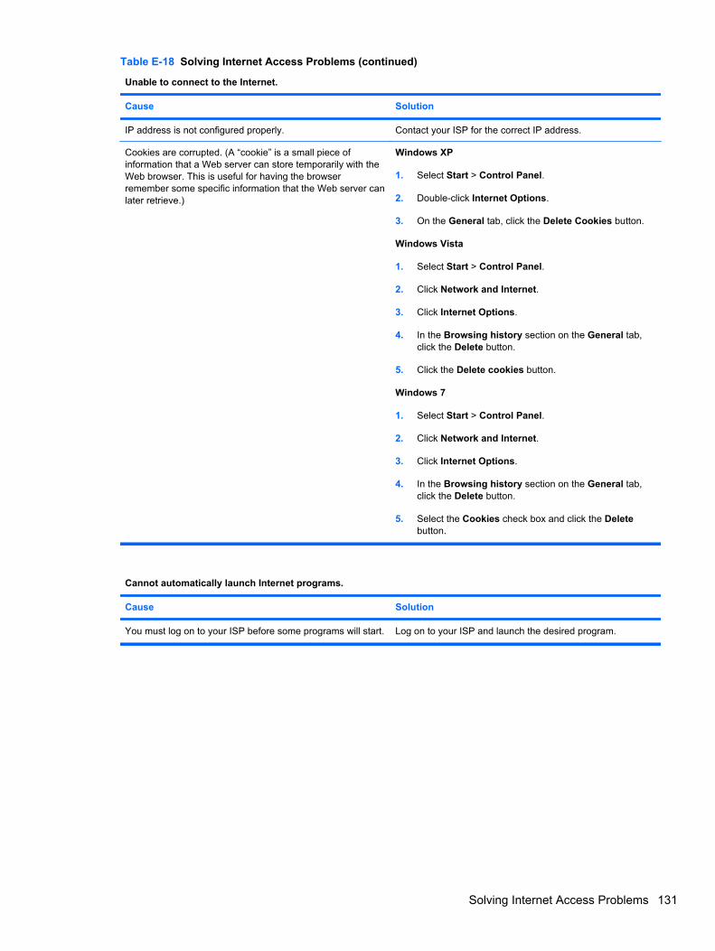
Unable to connect to the Internet.
Cause Solution
IP address is not configured properly. Contact your ISP for the correct IP address.
Cookies are corrupted. (A “cookie” is a small piece ofinformation that a Web server can store temporarily with theWeb browser. This is useful for having the browserremember some specific information that the Web server canlater retrieve.)
Windows XP
1. Select Start > Control Panel.
2. Double-click Internet Options.
3. On the General tab, click the Delete Cookies button.
Windows Vista
1. Select Start > Control Panel.
2. Click Network and Internet.
3. Click Internet Options.
4. In the Browsing history section on the General tab,click the Delete button.
5. Click the Delete cookies button.
Windows 7
1. Select Start > Control Panel.
2. Click Network and Internet.
3. Click Internet Options.
4. In the Browsing history section on the General tab,click the Delete button.
5. Select the Cookies check box and click the Deletebutton.
Cannot automatically launch Internet programs.
Cause Solution
You must log on to your ISP before some programs will start. Log on to your ISP and launch the desired program.
Table E-18 Solving Internet Access Problems (continued)
Solving Internet Access Problems 131

Internet takes too long to download Web sites.
Cause Solution
Modem is not set up properly. Verify that the modem is connected and communicatingproperly.
Windows XP
1. Select Start > Control Panel.
2. Double-click System.
3. Click the Hardware tab.
4. In the Device Manager area, click the Device Managerbutton.
5. Double-click Modems.
6. Double-click Agere Systems PCI-SV92PP SoftModem.
7. On the General tab, click Diagnostics.
8. Click Query Modem. A “Success” response indicatesthe modem is connected and working properly.
Windows Vista
1. Select Start > Control Panel.
2. Click on System and Maintenance.
3. Click on System.
4. In the Tasks list, select Device Manager.
5. Double-click Modems.
6. Double-click Agere Systems PCI-SV92PP SoftModem.
7. On the General tab, click Diagnostics.
8. Click Query Modem. A “Success” response indicatesthe modem is connected and working properly.
Windows 7
1. Select Start > Control Panel.
2. Click on Hardware and Sound.
3. Click on Device Manager.
4. Double-click Modems.
5. Double-click Agere Systems PCI-SV92PP SoftModem.
6. On the General tab, click Diagnostics.
7. Click Query Modem. A “Success” response indicatesthe modem is connected and working properly.
Table E-18 Solving Internet Access Problems (continued)
132 Appendix E Troubleshooting Without Diagnostics
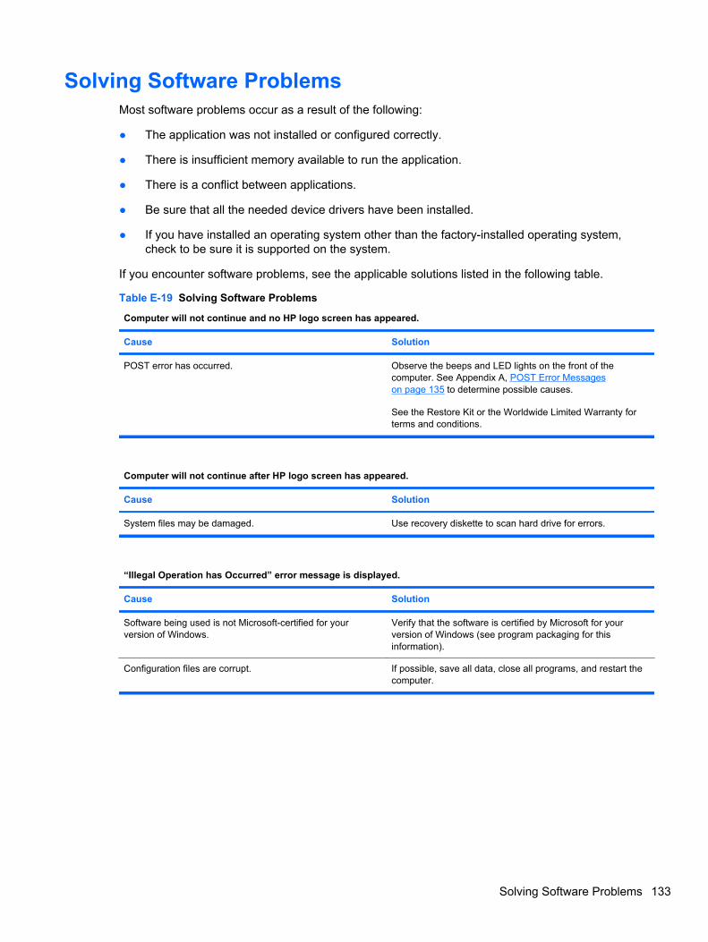
Solving Software ProblemsMost software problems occur as a result of the following:
● The application was not installed or configured correctly.
● There is insufficient memory available to run the application.
● There is a conflict between applications.
● Be sure that all the needed device drivers have been installed.
● If you have installed an operating system other than the factory-installed operating system,check to be sure it is supported on the system.
If you encounter software problems, see the applicable solutions listed in the following table.
Table E-19 Solving Software Problems
Computer will not continue and no HP logo screen has appeared.
Cause Solution
POST error has occurred. Observe the beeps and LED lights on the front of thecomputer. See Appendix A, POST Error Messageson page 135 to determine possible causes.
See the Restore Kit or the Worldwide Limited Warranty forterms and conditions.
Computer will not continue after HP logo screen has appeared.
Cause Solution
System files may be damaged. Use recovery diskette to scan hard drive for errors.
“Illegal Operation has Occurred” error message is displayed.
Cause Solution
Software being used is not Microsoft-certified for yourversion of Windows.
Verify that the software is certified by Microsoft for yourversion of Windows (see program packaging for thisinformation).
Configuration files are corrupt. If possible, save all data, close all programs, and restart thecomputer.
Solving Software Problems 133

Contacting Customer SupportFor help and service, contact an authorized reseller or dealer. To locate a reseller or dealer near you,visit http://www.hp.com.
NOTE: If you take the computer to an authorized reseller, dealer, or service provider for service,remember to provide the setup and power-on passwords if they are set.
Refer to the number listed in the warranty or in the Support Telephone Numbers guide for technicalassistance.
134 Appendix E Troubleshooting Without Diagnostics

F POST Error Messages
This appendix lists the error codes, error messages, and the various indicator light and audiblesequences that you may encounter during Power-On Self-Test (POST) or computer restart, theprobable source of the problem, and steps you can take to resolve the error condition.
POST Message Disabled suppresses most system messages during POST, such as memory countand non-error text messages. If a POST error occurs, the screen will display the error message. Tomanually switch to the POST Messages Enabled mode during POST, press any key (except F10,F11, or F12). The default mode is POST Message Disabled.
The speed at which the computer loads the operating system and the extent to which it is tested aredetermined by the POST mode selection.
Quick Boot is a fast startup process that does not run all of the system level tests, such as thememory test. Full Boot runs all of the ROM-based system tests and takes longer to complete.
Full Boot may also be enabled to run every 1 to 30 days on a regularly scheduled basis. To establishthe schedule, reconfigure the computer to the Full Boot Every x Days mode, using Computer Setup.
135
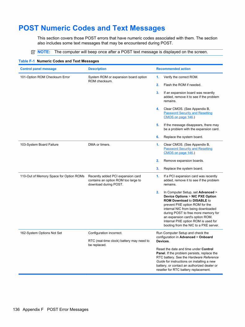
POST Numeric Codes and Text MessagesThis section covers those POST errors that have numeric codes associated with them. The sectionalso includes some text messages that may be encountered during POST.
NOTE: The computer will beep once after a POST text message is displayed on the screen.
Table F-1 Numeric Codes and Text Messages
Control panel message Description Recommended action
101-Option ROM Checksum Error System ROM or expansion board optionROM checksum.
1. Verify the correct ROM.
2. Flash the ROM if needed.
3. If an expansion board was recentlyadded, remove it to see if the problemremains.
4. Clear CMOS. (See Appendix B,Password Security and ResettingCMOS on page 146.)
5. If the message disappears, there maybe a problem with the expansion card.
6. Replace the system board.
103-System Board Failure DMA or timers. 1. Clear CMOS. (See Appendix B,Password Security and ResettingCMOS on page 146.)
2. Remove expansion boards.
3. Replace the system board.
110-Out of Memory Space for Option ROMs Recently added PCI expansion cardcontains an option ROM too large todownload during POST.
1. If a PCI expansion card was recentlyadded, remove it to see if the problemremains.
2. In Computer Setup, set Advanced >Device Options > NIC PXE OptionROM Download to DISABLE toprevent PXE option ROM for theinternal NIC from being downloadedduring POST to free more memory foran expansion card's option ROM.Internal PXE option ROM is used forbooting from the NIC to a PXE server.
162-System Options Not Set Configuration incorrect.
RTC (real-time clock) battery may need tobe replaced.
Run Computer Setup and check theconfiguration in Advanced > OnboardDevices.
Reset the date and time under ControlPanel. If the problem persists, replace theRTC battery. See the Hardware ReferenceGuide for instructions on installing a newbattery, or contact an authorized dealer orreseller for RTC battery replacement.
136 Appendix F POST Error Messages

Control panel message Description Recommended action
163-Time & Date Not Set Invalid time or date in configurationmemory.
RTC (real-time clock) battery may need tobe replaced.
Reset the date and time under ControlPanel (Computer Setup can also be used).If the problem persists, replace the RTCbattery. See the Hardware Reference Guidefor instructions on installing a new battery,or contact an authorized dealer or resellerfor RTC battery replacement.
163-Time & Date Not Set CMOS jumper may not be properlyinstalled.
Check for proper placement of the CMOSjumper if applicable.
164-MemorySize Error Memory amount has changed since the lastboot (memory added or removed).
Press the F1 key to save the memorychanges.
164-MemorySize Error Memory configuration incorrect. 1. Run Computer Setup or Windowsutilities.
2. Make sure the memory module(s) areinstalled properly.
3. If third-party memory has been added,test using HP-only memory.
4. Verify proper memory module type.
201-Memory Error RAM failure. 1. Ensure memory modules are correctlyinstalled.
2. Verify proper memory module type.
3. Remove and replace the identifiedfaulty memory module(s).
4. If the error persists after replacingmemory modules, replace the systemboard.
213-Incompatible Memory Module inMemory Socket(s) X, X, ...
A memory module in memory socketidentified in the error message is missingcritical SPD information, or is incompatiblewith the chipset.
1. Verify proper memory module type.
2. Try another memory socket.
3. Replace DIMM with a moduleconforming to the SPD standard.
214-DIMM Configuration Warning Populated DIMM Configuration is notoptimized.
Rearrange the DIMMs so that each channelhas the same amount of memory.
219-ECC Memory Module Detected ECCModules not supported on this Platform
Recently added memory module(s) supportECC memory error correction.
1. If additional memory was recentlyadded, remove it to see if the problemremains.
2. Check product documentation formemory support information.
301-Keyboard Error Keyboard failure. 1. Reconnect keyboard with computerturned off.
2. Check connector for bent or missingpins.
3. Ensure that none of the keys aredepressed.
4. Replace keyboard.
Table F-1 Numeric Codes and Text Messages (continued)
POST Numeric Codes and Text Messages 137

Control panel message Description Recommended action
303-Keyboard Controller Error I/O board keyboard controller. 1. Reconnect keyboard with computerturned off.
2. Replace the system board.
304-Keyboard or System Unit Error Keyboard failure. 1. Reconnect the keyboard with computerturned off.
2. Ensure that none of the keys aredepressed.
3. Replace the keyboard.
4. Replace the system board.
501-Display Adapter Failure Graphics display controller. 1. Reseat the graphics card(if applicable).
2. Clear CMOS. (See Appendix B,Password Security and ResettingCMOS on page 146.)
3. Verify monitor is attached and turnedon.
4. Replace the graphics card (if possible).
510-Flash Screen Image Corrupted Flash Screen image has errors. Reflash the system ROM with the latestBIOS image.
511-CPU, CPUA, or CPUB Fan notDetected
CPU fan is not connected or may havemalfunctioned.
1. Reseat CPU fan.
2. Reseat fan cable.
3. Replace CPU fan.
512-Chassis, Rear Chassis, or FrontChassis Fan not Detected
Chassis, rear chassis, or front chassis fan isnot connected or may have malfunctioned.
1. Reseat chassis, rear chassis, or frontchassis fan.
2. Reseat fan cable.
3. Replace chassis, rear chassis, or frontchassis fan.
513-Front Chassis fan not detected Front chassis fan is not connected or mayhave malfunctioned.
1. Reseat front chassis fan.
2. Reseat fan cable.
3. Replace front chassis fan.
515-Power Supply fan not detected Power supply fan is not connected or mayhave malfunctioned.
1. Reseat power supply fan.
2. Reseat fan cable.
3. Replace power supply fan.
601-Diskette Controller Error Diskette controller circuitry or floppy drivecircuitry incorrect.
1. Check and/or replace cables.
2. Clear CMOS. (See Appendix B,Password Security and ResettingCMOS on page 146.)
3. Replace diskette drive.
4. Replace the system board.
Table F-1 Numeric Codes and Text Messages (continued)
138 Appendix F POST Error Messages

Control panel message Description Recommended action
605-Diskette Drive Type Error Mismatch in drive type. 1. Disconnect any other diskettecontroller devices (tape drives).
2. Clear CMOS. (See Appendix B,Password Security and ResettingCMOS on page 146.)
660-Display cache is detected unreliable Integrated graphics controller display cacheis not working properly and will be disabled.
Replace system board if minimal graphicsdegrading is an issue.
912-Computer Cover Has Been RemovedSince Last System Startup
Computer cover was removed since lastsystem startup.
No action required.
917-Front Audio Not Connected Front audio harness has been detached orunseated from motherboard.
Reconnect or replace front audio harness.
918-Front USB Not Connected Front USB harness has been detached orunseated from motherboard.
Reconnect or replace front USB harness.
921-Device in PCI Express slot failed toinitialize
There is an incompatibility/problem with thisdevice and the system or PCI Express Linkcould not be retrained to an x1.
Try rebooting the system. If the errorreoccurs, the device may not work with thissystem
1151-Serial Port A Address ConflictDetected
Both external and internal serial ports areassigned to COM1.
1. Remove any serial port expansioncards.
2. Clear CMOS. (See Appendix B,Password Security and ResettingCMOS on page 146.)
3. Reconfigure card resources and/or runComputer Setup or Windows utilities.
1152-Serial Port B Address ConflictDetected
Both external and internal serial ports areassigned to COM2.
1. Remove any serial port expansioncards.
2. Clear CMOS. (See Appendix B,Password Security and ResettingCMOS on page 146.)
3. Reconfigure card resources and/or runComputer Setup or Windows utilities.
1155-Serial Port Address Conflict Detected Both external and internal serial ports areassigned to same IRQ.
1. Remove any serial port expansioncards.
2. Clear CMOS. (See Appendix B,Password Security and ResettingCMOS on page 146.)
3. Reconfigure card resources and/or runComputer Setup or Windows utilities.
1720-SMART Hard Drive Detects ImminentFailure
Hard drive is about to fail. (Some harddrives have a hard drive firmware patch thatwill fix an erroneous error message.)
1. Determine if hard drive is giving correcterror message. Enter Computer Setupand run the Drive Protection Systemtest under Storage > DPS Self-test.
2. Apply hard drive firmware patchif applicable. (Available athttp://www.hp.com/support.)
3. Back up contents and replace harddrive.
Table F-1 Numeric Codes and Text Messages (continued)
POST Numeric Codes and Text Messages 139

Control panel message Description Recommended action
1796-SATA Cabling Error One or more SATA devices are improperlyattached. For optimal performance, theSATA 0 and SATA 1 connectors must beused before SATA 2 and SATA 3.
Ensure SATA connectors are used inascending order. For one device, use SATA0. For two devices, use SATA 0 and SATA1. For three devices, use SATA 0, SATA 1,and SATA 2.
1801-Microcode Patch Error Processor is not supported by ROM BIOS. 1. Upgrade BIOS to proper version.
2. Change the processor.
2200-PMM Allocation Error during MEBxDownload
Memory error during POST execution of theManagement Engine (ME) BIOS Extensionsoption ROM.
1. Reboot the computer.
2. Unplug the power cord, re-seat thememory modules, and reboot thecomputer.
3. If the memory configuration wasrecently changed, unplug thecomputer, restore the original memoryconfiguration, and reboot thecomputer.
4. If the error persists, replace the systemboard.
2201-MEBx Module did not checksumcorrectly
Memory error during POST execution of theManagement Engine (ME) BIOS Extensionsoption ROM.
1. Reboot the computer.
2. Unplug the power cord, re-seat thememory modules, and reboot thecomputer.
3. If the memory configuration wasrecently changed, unplug the powercord, restore the original memoryconfiguration, and reboot thecomputer.
4. If the error persists, replace the systemboard.
2202-PMM Deallocation Error during MEBxcleanup
Memory error during POST execution of theManagement Engine (ME) BIOS Extensionsoption ROM.
1. Reboot the computer.
2. Unplug the power cord, re-seat thememory modules, and reboot thecomputer.
3. If the memory configuration wasrecently changed, unplug the powercord, restore the original memoryconfiguration, and reboot thecomputer.
4. If the error persists, replace the systemboard.
2211-Memory not configured correctly forproper MEBx execution
SODIMM1 is not installed. Make sure there is a memory module in theblack SODIMM1 socket and that it isproperly seated.
Table F-1 Numeric Codes and Text Messages (continued)
140 Appendix F POST Error Messages

Control panel message Description Recommended action
2212-USB Key Provisioning failure writing todevice
USB device used for USB key provisioningwill not allow BIOS to update provision fileproperly.
1. Try a different USB key device forprovisioning.
2. If the error persists, update to the latestBIOS version and ME firmwareversion.
3. If the error still persists, replace thesystem board.
2217-ME Firmware Version request failure ME firmware is not properly responding toBIOS query for version information.
1. Reboot the computer.
2. If the error persists, update to the latestBIOS version and ME firmwareversion.
3. If the error still persists, replace thesystem board.
2218-ME Firmware Version should beupdated
ME firmware must be updated to matchcurrent functionality contained in the systemBIOS.
1. Update to the latest ME firmwareversion.
2. If the error persists and system BIOShas been recently updated, restoreprevious system BIOS version.
3. If the error still persists, replace thesystem board.
2219-USB Key Provisioning file has invalidheader identifier
Provisioning file contained on the USB keyhas been corrupted or is not a valid versionfor the current ME firmware.
1. Recreate the provisioning file usingthird party management consolesoftware.
2. If the error persists and system BIOShas been recently updated, restoreprevious system BIOS version.Otherwise, update the ME firmwareversion.
3. If the error still persists, replace thesystem board.
2220-USB Key Provisioning file hasmismatch version
Provisioning file contained on the USB keyis not a valid version for the current MEfirmware.
1. Reboot the computer.
2. If the error persists and system BIOShas been recently updated, restoreprevious system BIOS version.Otherwise, update the ME firmwareversion.
3. If the error still persists, replace thesystem board.
2230-General error during MEBx execution Error occurred during MEBx executionwhich fails into the “General” grouping.Status information displayed along with theerror provides further clarity into the failure.MEBx handles transference of informationbetween the system BIOS and MEfirmware.
1. Reboot the computer.
2. If the error persists, update to the latestBIOS version and ME firmwareversion.
3. If the error still persists, replace thesystem board.
Table F-1 Numeric Codes and Text Messages (continued)
POST Numeric Codes and Text Messages 141

Control panel message Description Recommended action
2231-ME error during MEBx execution Error occurred during MEBx executionwhich fails into “ME” grouping.
1. Reboot the computer.
2. If the error persists, update to the latestBIOS version and ME firmwareversion.
3. If the error still persists, replace thesystem board.
2232-AMT error during MEBx execution Error occurred during MEBx executionwhich fails into “AMT” grouping.
1. Reboot the computer.
2. If the error persists, update to the latestBIOS version and ME firmwareversion.
3. If the error still persists, replace thesystem board.
2233-HECI error during MEBx execution Error occurred during MEBx executionwhich fails into “MEI or HECI” grouping.
1. Reboot the computer.
2. If the error persists, update to the latestBIOS version and ME firmwareversion.
3. If the error still persists, replace thesystem board.
2239-ME image lock failure Special system configurations with reducedME firmware image require BIOS control ofME firmware upgrading. A failure hasoccurred after the ME firmware updateprocess in which the BIOS could not relockthe ME firmware region.
1. Reboot the computer.
2. If the error persists, update to the latestBIOS version and ME firmwareversion.
3. If the error still persists, replace thesystem board.
2240-ME image unlock failure Special system configurations with reducedME firmware image require BIOS control ofME firmware upgrading. A failure hasoccurred prior to the ME firmware updateprocess in which the BIOS could not unlockthe ME firmware region.
1. Reboot the computer.
2. If the error persists, update to the latestBIOS version and ME firmwareversion.
3. If the error still persists, replace thesystem board.
Invalid Electronic Serial Number Electronic serial number is missing. Enter the correct serial number in ComputerSetup.
Network Server Mode Active and NoKeyboard Attached
Keyboard failure while Network ServerMode enabled.
1. Reconnect keyboard with computerturned off.
2. Check connector for bent or missingpins.
3. Ensure that none of the keys aredepressed.
4. Replace keyboard.
Parity Check 2 Parity RAM failure. Run Computer Setup and Diagnosticutilities.
Table F-1 Numeric Codes and Text Messages (continued)
142 Appendix F POST Error Messages
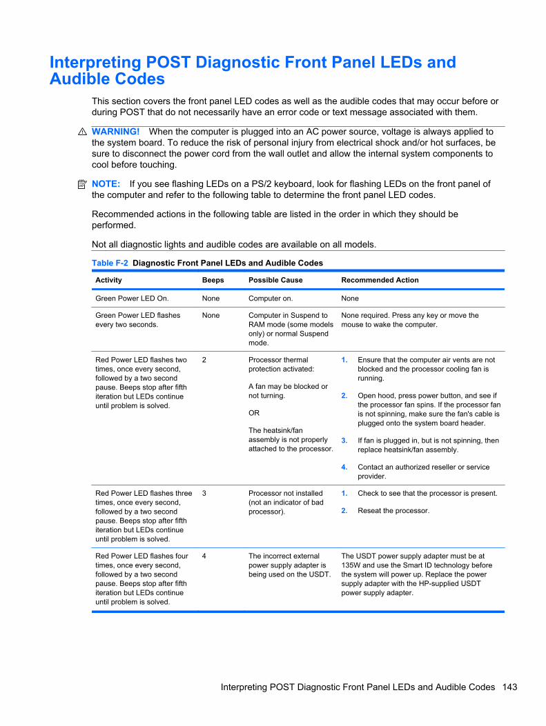
Interpreting POST Diagnostic Front Panel LEDs andAudible Codes
This section covers the front panel LED codes as well as the audible codes that may occur before orduring POST that do not necessarily have an error code or text message associated with them.
WARNING! When the computer is plugged into an AC power source, voltage is always applied tothe system board. To reduce the risk of personal injury from electrical shock and/or hot surfaces, besure to disconnect the power cord from the wall outlet and allow the internal system components tocool before touching.
NOTE: If you see flashing LEDs on a PS/2 keyboard, look for flashing LEDs on the front panel ofthe computer and refer to the following table to determine the front panel LED codes.
Recommended actions in the following table are listed in the order in which they should beperformed.
Not all diagnostic lights and audible codes are available on all models.
Table F-2 Diagnostic Front Panel LEDs and Audible Codes
Activity Beeps Possible Cause Recommended Action
Green Power LED On. None Computer on. None
Green Power LED flashesevery two seconds.
None Computer in Suspend toRAM mode (some modelsonly) or normal Suspendmode.
None required. Press any key or move themouse to wake the computer.
Red Power LED flashes twotimes, once every second,followed by a two secondpause. Beeps stop after fifthiteration but LEDs continueuntil problem is solved.
2 Processor thermalprotection activated:
A fan may be blocked ornot turning.
OR
The heatsink/fanassembly is not properlyattached to the processor.
1. Ensure that the computer air vents are notblocked and the processor cooling fan isrunning.
2. Open hood, press power button, and see ifthe processor fan spins. If the processor fanis not spinning, make sure the fan's cable isplugged onto the system board header.
3. If fan is plugged in, but is not spinning, thenreplace heatsink/fan assembly.
4. Contact an authorized reseller or serviceprovider.
Red Power LED flashes threetimes, once every second,followed by a two secondpause. Beeps stop after fifthiteration but LEDs continueuntil problem is solved.
3 Processor not installed(not an indicator of badprocessor).
1. Check to see that the processor is present.
2. Reseat the processor.
Red Power LED flashes fourtimes, once every second,followed by a two secondpause. Beeps stop after fifthiteration but LEDs continueuntil problem is solved.
4 The incorrect externalpower supply adapter isbeing used on the USDT.
The USDT power supply adapter must be at135W and use the Smart ID technology beforethe system will power up. Replace the powersupply adapter with the HP-supplied USDTpower supply adapter.
Interpreting POST Diagnostic Front Panel LEDs and Audible Codes 143

Activity Beeps Possible Cause Recommended Action
Red Power LED flashes fivetimes, once every second,followed by a two secondpause. Beeps stop after fifthiteration but LEDs continueuntil problem is solved.
5 Pre-video memory error. CAUTION: To avoid damage to the DIMMs orthe system board, you must unplug the computerpower cord before attempting to reseat, install, orremove a DIMM module.
1. Reseat DIMMs.
2. Make sure a DIMM is installed in the blackDIMM connector first if there is only oneDIMM in the system.
3. Replace third-party memory with HPmemory.
4. Replace the system board.
Red Power LED flashes sixtimes, once every second,followed by a two secondpause. Beeps stop after fifthiteration but LEDs continueuntil problem is solved.
6 Pre-video graphics error. For systems with a graphics card:
1. Reseat the graphics card.
2. Replace the graphics card.
3. Replace the system board.
For systems with integrated graphics, replacethe system board.
Red Power LED flashesseven times, once everysecond, followed by a twosecond pause. Beeps stopafter fifth iteration but LEDscontinue until problem issolved.
7 System board failure(ROM detected failureprior to video).
Replace the system board.
Red Power LED flashes eighttimes, once every second,followed by a two secondpause. Beeps stop after fifthiteration but LEDs continueuntil problem is solved.
8 Invalid ROM based onbad checksum.
1. Reflash the system ROM with the latestBIOS image.
2. Replace the system board.
Red Power LED flashes ninetimes, once every second,followed by a two secondpause. Beeps stop after fifthiteration but LEDs continueuntil problem is solved.
9 System powers on but isunable to boot.
1. Check that the voltage selector, located onthe rear of the power supply (somemodels), is set to the appropriate voltage.Proper voltage setting depends on yourregion.
2. Unplug the AC power cord from thecomputer, wait 30 seconds, then plug thepower cord back in to the computer.
3. Replace the system board.
4. Replace the processor.
Red Power LED flashes tentimes, once every second,followed by a two secondpause. Beeps stop after fifthiteration but LEDs continueuntil problem is solved.
10 Bad option card. 1. Check each option card by removing thecard (one at a time if multiple cards), thenpower on the system to see if fault goesaway.
2. Once a bad card is identified, remove andreplace the bad option card.
3. Replace the system board.
Table F-2 Diagnostic Front Panel LEDs and Audible Codes (continued)
144 Appendix F POST Error Messages

Activity Beeps Possible Cause Recommended Action
Red Power LED flasheseleven times, once everysecond, followed by a twosecond pause. Beeps stopafter fifth iteration but LEDscontinue until problem issolved.
11 The current processordoes not support afeature previouslyenabled on this system.
1. Install a TXT capable processor.
2. Disable TXT in the Computer Setup (F10)utility.
3. Reinstall the original processor.
System does not power onand LEDs are not flashing.
None System unable to poweron.
Press and hold the power button for less than 4seconds. If the hard drive LED turns green, thepower button is working correctly. Try thefollowing:
1. Check that the voltage selector (somemodels), located on the rear of the powersupply, is set to the appropriate voltage.Proper voltage setting depends on yourregion.
2. Replace the system board.
OR
Press and hold the power button for less than 4seconds. If the hard drive LED does not turn ongreen then:
1. Check that the unit is plugged into aworking AC outlet.
2. Open hood and check that the power buttonharness is properly connected to thesystem board.
3. Check that both power supply cables areproperly connected to the system board.
4. Check to see if the 5V_aux light on thesystem board is turned on. If it is turned on,then replace the power button harness. Ifthe problem persists, replace the systemboard.
5. If the 5V_aux light on the system board isnot turned on, remove the expansion cardsone at a time until the 5V_aux light on thesystem board turns on. It the problempersists, replace the power supply.
Table F-2 Diagnostic Front Panel LEDs and Audible Codes (continued)
Interpreting POST Diagnostic Front Panel LEDs and Audible Codes 145

G Password Security and ResettingCMOS
This computer supports security password features, which can be established through the ComputerSetup Utilities menu.
This computer supports two security password features that are established through the ComputerSetup Utilities menu: setup password and power-on password. When you establish only a setuppassword, any user can access all the information on the computer except Computer Setup. Whenyou establish only a power-on password, the power-on password is required to access ComputerSetup and any other information on the computer. When you establish both passwords, only thesetup password will give you access to Computer Setup.
When both passwords are set, the setup password can also be used in place of the power-onpassword as an override to log in to the computer. This is a useful feature for a network administrator.
If you forget the password for the computer, you can clear that password so you can gain access tothe information on the computer by resetting the password jumper.
CAUTION: Pushing the CMOS button will reset CMOS values to factory defaults. It is important toback up the computer CMOS settings before resetting them in case they are needed later. Back up iseasily done through Computer Setup.
146 Appendix G Password Security and Resetting CMOS

Resetting the Password JumperTo disable the power-on or setup password features, or to clear the power-on or setup passwords,complete the following steps:
1. Shut down the operating system properly, then turn off the computer and any external devices,and disconnect the power cord from the power outlet.
2. With the power cord disconnected, press the power button again to drain the system of anyresidual power.
WARNING! To reduce the risk of personal injury from electrical shock and/or hot surfaces, besure to disconnect the power cord from the wall outlet, and allow the internal systemcomponents to cool before touching.
CAUTION: When the computer is plugged in, the power supply always has voltage applied tothe system board even when the unit is turned off. Failure to disconnect the power cord canresult in damage to the system.
Static electricity can damage the electronic components of the computer or optional equipment.Before beginning these procedures, ensure that you are discharged of static electricity by brieflytouching a grounded metal object. See the Safety & Regulatory Information guide for moreinformation.
3. Remove the computer cover or access panel.
4. Locate the header and jumper.
NOTE: The password jumper is green so that it can be easily identified. For assistancelocating the password jumper and other system board components, see the Illustrated Parts &Service Map (IPSM) for that particular system. The IPSM can be downloaded fromhttp://www.hp.com/support.
5. Remove the jumper from pins 1 and 2. Place the jumper on either pin 1 or 2, but not both, sothat it does not get lost.
6. Replace the computer cover or access panel.
7. Reconnect the external equipment.
8. Plug in the computer and turn on power. Allow the operating system to start. This clears thecurrent passwords and disables the password features.
9. To establish new passwords, repeat steps 1 through 4, replace the password jumper on pins 1and 2, then repeat steps 6 through 8. Establish the new passwords in Computer Setup.
Resetting the Password Jumper 147

Clearing and Resetting the CMOSThe computer’s configuration memory (CMOS) stores information about the computer’s configuration.
The CMOS button resets CMOS but does not clear the power-on and setup passwords.
Clearing CMOS will clear the Active Management Technology (AMT) settings in the ManagementEngine BIOS Extension (MEBx), including the password. The password will default to “admin” and willneed to be reset. The AMT settings will also need to be reset. To access the MEBx, press Ctrl+Pduring POST.
1. Turn off the computer and any external devices, and disconnect the power cord from the poweroutlet.
2. Disconnect the keyboard, monitor, and any other external equipment connected to the computer.
WARNING! To reduce the risk of personal injury from electrical shock and/or hot surfaces, besure to disconnect the power cord from the wall outlet, and allow the internal systemcomponents to cool before touching.
CAUTION: When the computer is plugged in, the power supply always has voltage applied tothe system board even when the unit is turned off. Failure to disconnect the power cord canresult in damage to the system.
Static electricity can damage the electronic components of the computer or optional equipment.Before beginning these procedures, ensure that you are discharged of static electricity by brieflytouching a grounded metal object. See the Safety & Regulatory Information guide for moreinformation.
3. Remove the computer cover or access panel.
CAUTION: Pushing the CMOS button will reset CMOS values to factory defaults. It isimportant to back up the computer CMOS settings before resetting them in case they areneeded later. Back up is easily done through Computer Setup.
148 Appendix G Password Security and Resetting CMOS

4. Locate, press, and hold the CMOS button in for five seconds.
NOTE: Make sure you have disconnected the AC power cord from the wall outlet. The CMOSbutton will not clear CMOS if the power cord is connected.
Figure G-1 CMOS button
NOTE: For assistance locating the CMOS button and other system board components, see theIllustrated Parts & Service Map (IPSM) for that particular system.
5. Replace the computer cover or access panel.
6. Reconnect the external devices.
7. Plug in the computer and turn on power.
NOTE: You will receive POST error messages after clearing CMOS and rebooting advisingyou that configuration changes have occurred. Use Computer Setup to reset any special systemsetups along with the date and time.
Clearing and Resetting the CMOS 149

H Drive Protection System (DPS)
The Drive Protection System (DPS) is a diagnostic tool built into the hard drives installed in somecomputers. DPS is designed to help diagnose problems that might result in unwarranted hard drivereplacement.
When these systems are built, each installed hard drive is tested using DPS, and a permanent recordof key information is written onto the drive. Each time DPS is run, test results are written to the harddrive. Your service provider can use this information to help diagnose conditions that caused you torun the DPS software.
Running DPS will not affect any programs or data stored on the hard drive. The test resides in thehard drive firmware and can be executed even if the computer will not boot to an operating system.The time required to execute the test depends on the manufacturer and size of the hard drive; in mostcases, the test will take approximately two minutes per gigabyte.
Use DPS when you suspect a hard drive problem. If the computer reports a SMART Hard DriveDetect Imminent Failure message, there is no need to run DPS; instead, back up the information onthe hard drive and contact a service provider for a replacement hard drive.
150 Appendix H Drive Protection System (DPS)

Accessing DPS Through Computer SetupWhen the computer does not power on properly you should use Computer Setup to access the DPSprogram. To access DPS, perform the following steps:
1. Turn on or restart the computer.
2. When the F10 Setup message appears in the lower-right corner of the screen, press the F10key.
NOTE: If you do not press the F10 key while the message is displayed, you must turn thecomputer off, then on again, to access the utility.
A choice of five headings appears in the Computer Setup Utilities menu: File, Storage,Security, Power, and Advanced.
3. Select Storage > DPS Self-Test.
The screen will display the list of DPS-capable hard drives that are installed on the computer.
NOTE: If no DPS-capable hard drives are installed, the DPS Self-Test option will not appearon the screen.
4. Select the hard drive to be tested and follow the screen prompts to complete the testing process.
When the test has been completed, one of three messages will be displayed:
● Test Succeeded. Completion Code 0.
● Test Aborted. Completion Code 1 or 2.
● Test Failed. Drive Replacement Recommended. Completion Code 3 through 14.
If the test failed, the completion code should be recorded and reported to your service provider forhelp in diagnosing the computer problem.
Accessing DPS Through Computer Setup 151

I Specifications
Table I-1 Specifications
Desktop Dimensions (in the desktop position)
Height
Width
Depth
(depth will increase if the computer is equipped with a port security bracket)
2.60 in
9.90 in
10.00 in
6.6 cm
25.1 cm
25.4 cm
Approximate Weight 6.75 lb 3.07 kg
Weight Supported (maximum distributed load in desktop position) 77 lb 35 kg
Temperature Range (values subject to change with increasing altitude above sealevel)
Operating
Nonoperating
50° to 95° F
-22° to 140° F
10° to 35° C
-30° to 60° C
NOTE: Operating temperature is derated 1.0° C per 300 m (1,000 ft) to 3,000 m (10,000 ft) above sea level, no directsustained sunlight. Maximum rate of change is 10° C (50° F)/Hr. The upper limit may be limited by the type and number ofoptions installed.
Relative Humidity (noncondensing)
Operating (28° C (82.4° F) max wet bulb)
Nonoperating (38.7° C (101.66° F) max wet bulb)
10-90%
5-95%
10-90%
5-95%
Maximum Altitude (unpressurized)
Operating
Nonoperating
10,000 ft
30,000 ft
3,048 m
9,144 m
Heat Dissipation
Maximum
Typical (idle)
549 BTU/hr
133 BTU/hr
132 kg-cal/hr
33.5 kg-cal/hr
Power Supply
Operating Voltage Range
Rated Voltage Range1
Rated Line Frequency
90-264 VAC
100-240 VAC
50-60 Hz
Power Output 135 W
152 Appendix I Specifications

Rated Input Current (maximum)1 2.4A @ 100VAC 1.2A @ 200VAC
1 This system utilizes an active power factor corrected external power supply. This allows the system to pass the CE markrequirements for use in the countries of the European Union. The active power factor corrected power supply also has theadded benefit of not requiring an input voltage range select switch.
Table I-1 Specifications (continued)
153

Index
Symbols/Numerics4-pin power pin assignments 716-pin power pin assignments 71
Aaccess panel
locking and unlocking 32removing 38
access panel, locked 94audible codes 143audio
connectors 1audio problems 110
Bbacking up files 76, 80Backup and Restore 76, 77Backup and Restore
Center 80, 81battery
disposal 29removal and replacement 63
beep codes 143bezel, removing 39boot problems 127booting options
Full Boot 135Quick Boot 135
Ccable connections 45cable lock 32cable management 45cable pinouts, SATA data 20card reader, removal and
replacement 56cautions
AC power 22cables 28cooling fan 27
electrostatic discharge 23keyboard cleaning 27keyboard keys 27
CD-ROM or DVD problems 125chassis, illustrated 22cleaning
computer 26mouse 27safety precautions 26
CMOSbacking up 136clearing and resetting 148
componentsfront panel 1rear panel 2
computerchanging from desktop to
tower 65cleaning 26security locks 32specifications 152
connectoraudio line-in 2audio line-out 2DisplayPort monitor 2headphone 1power cord 2PS/2 keyboard 2PS/2 mouse 2RJ-45 2VGA monitor 2
connector pin assignments 67country power cord set
requirements 75creating a backup 76, 80Customer Support 90, 134
Ddiagnostics utility 84disassembly preparation 30
diskette problems 98DisplayPort monitor connector
identified 2pin assignments 70
driveinstalling optical drive 48removing optical drive 46
Drive Protection System(DPS) 150
Eelectrostatic discharge (ESD)
preventing damage 23error
codes 90, 143messages 136
ethernetBNC pin assignments 67RJ-45 pin assignments 68
FF11 recovery 78, 82fan, power supply 27flash drive problems 128flashing LEDs 143front bezel
removing and replacing 39removing blanks 40security 36
front fan, removal andreplacement 55
front panelcomponents 1
front panel problems 129
Ggeneral problems 93grounding methods 24
154 Index
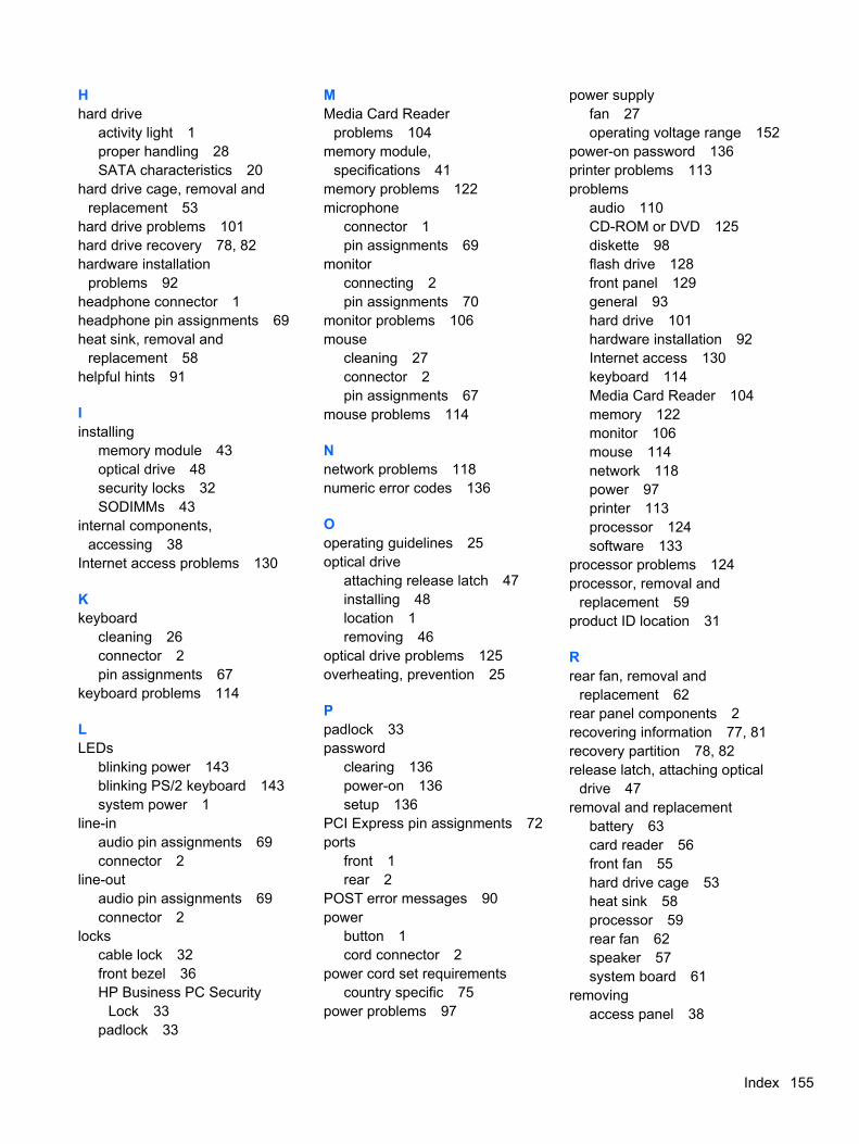
Hhard drive
activity light 1proper handling 28SATA characteristics 20
hard drive cage, removal andreplacement 53
hard drive problems 101hard drive recovery 78, 82hardware installation
problems 92headphone connector 1headphone pin assignments 69heat sink, removal and
replacement 58helpful hints 91
Iinstalling
memory module 43optical drive 48security locks 32SODIMMs 43
internal components,accessing 38
Internet access problems 130
Kkeyboard
cleaning 26connector 2pin assignments 67
keyboard problems 114
LLEDs
blinking power 143blinking PS/2 keyboard 143system power 1
line-inaudio pin assignments 69connector 2
line-outaudio pin assignments 69connector 2
lockscable lock 32front bezel 36HP Business PC Security
Lock 33padlock 33
MMedia Card Reader
problems 104memory module,
specifications 41memory problems 122microphone
connector 1pin assignments 69
monitorconnecting 2pin assignments 70
monitor problems 106mouse
cleaning 27connector 2pin assignments 67
mouse problems 114
Nnetwork problems 118numeric error codes 136
Ooperating guidelines 25optical drive
attaching release latch 47installing 48location 1removing 46
optical drive problems 125overheating, prevention 25
Ppadlock 33password
clearing 136power-on 136setup 136
PCI Express pin assignments 72ports
front 1rear 2
POST error messages 90power
button 1cord connector 2
power cord set requirementscountry specific 75
power problems 97
power supplyfan 27operating voltage range 152
power-on password 136printer problems 113problems
audio 110CD-ROM or DVD 125diskette 98flash drive 128front panel 129general 93hard drive 101hardware installation 92Internet access 130keyboard 114Media Card Reader 104memory 122monitor 106mouse 114network 118power 97printer 113processor 124software 133
processor problems 124processor, removal and
replacement 59product ID location 31
Rrear fan, removal and
replacement 62rear panel components 2recovering information 77, 81recovery partition 78, 82release latch, attaching optical
drive 47removal and replacement
battery 63card reader 56front fan 55hard drive cage 53heat sink 58processor 59rear fan 62speaker 57system board 61
removingaccess panel 38
Index 155
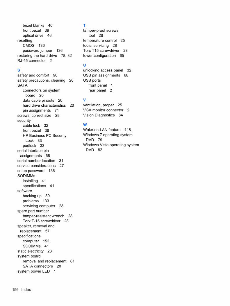
bezel blanks 40front bezel 39optical drive 46
resettingCMOS 136password jumper 136
restoring the hard drive 78, 82RJ-45 connector 2
Ssafety and comfort 90safety precautions, cleaning 26SATA
connectors on systemboard 20
data cable pinouts 20hard drive characteristics 20pin assignments 71
screws, correct size 28security
cable lock 32front bezel 36HP Business PC Security
Lock 33padlock 33
serial interface pinassignments 68
serial number location 31service considerations 27setup password 136SODIMMs
installing 41specifications 41
softwarebacking up 89problems 133servicing computer 28
spare part numbertamper-resistant wrench 28Torx T-15 screwdriver 28
speaker, removal andreplacement 57
specificationscomputer 152SODIMMs 41
static electricity 23system board
removal and replacement 61SATA connectors 20
system power LED 1
Ttamper-proof screws
tool 28temperature control 25tools, servicing 28Torx T15 screwdriver 28tower configuration 65
Uunlocking access panel 32USB pin assignments 68USB ports
front panel 1rear panel 2
Vventilation, proper 25VGA monitor connector 2Vision Diagnostics 84
WWake-on-LAN feature 118Windows 7 operating system
DVD 79Windows Vista operating system
DVD 82
156 Index