Presented to: Games for Health Conference 2006 Presented by: Randy Brown CTO, Virtual Heroes Inc.

Hozer Video Games! - Randy Crihfield
The main purpose of this document is to describe how to program games that are 8K, 16K, 32K, 64K, all the way up to 1MB. I explains multiple bank switching techniques, and. I also tried to explain the WHY so folks could go on from here to even bigger and better things. For my point of reference I use the standard 8K/16K board I use for just about everything, created by Chris Wilkson back in 1999. It turns out it can easily be done, and rather cheaply. The board now comes in a Sara and non-Sara variety, so yes games like Cave In can be done without a lot of fuss or muss (been there done that own one for myself). If you prefer using my �competitor� boards, there's a section at the end.
It was somewhat frustrating to test the GAL programming � after all as far as I know there are no 64K Sara game images out there to play around with for example. Finding some test bins was very beneficial, but I still needed them for the 1MB cart I have here on the table (Thanks Snail!). The original goal, the challenge one customer laid down for me, was to be able to further expand my ability to create carts for people and keep the price as ridiculously low as I could. In particular they wanted a 64K cartridge. I already make 8K/16K games for $16 which includes postage in the USA, so charging a little extra for the additional labor seemed reasonable.
My target for non-Sara games -
$11 for 2K/4K games (Same price since 1984!)$16 for 8K/16K games (Same price since 1999!)$16 for 32K games (Same price since 2001!)$20 for 64K games (Same price since, well, 2014!)
For the even larger games, hmmm.... Maybe I should simply say �market prices� like they do for lobsters. I mean until I see a run on 27c080 eprom based games buying them at quantity of 10 or less is pretty expensive. We'll see what I can do. I would greatly prefer that $25 be the most I would ever charge for any normal game.
My OTHER goal was to put this out into the public's hands so anyone and their brother could make their own games if they so chose. Back in 1984 when I first started making games I used to provide a schematic and dummy cookbook steps on how one might make their own game from scratch. Over the years scores and scores of people have emailed me in appreciation for sharing this info. I don't see why anyone should be denied the know how to make larger games. This is nothing new for me and I am hopeful many others will enjoy the hobby of actually making the games as much as I have.
Included here are good pics of some of the boards I use, as well as the actual programming! They are not the only possible way to make games but they work for most. If there is something I haven't quite explained well please drop me a line and I'll update this document as best I can. And if you invent a new bank switching scheme, or see an error in my code (or in this document!), please share the info with the TRUE community, folks like you and I, and ignore the knuckle heads who who want to hold on to a monopoly, and hold games hostage, just so they can charge high prices.
Happy gaming!
Randy CrihfieldHozer Video Games
Version 4.0, 7/2015
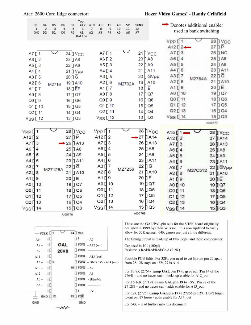
Atari 2600 Card Edge connector: Hozer Video Games! - Randy Crihfield
Denotes additional enabler used in bank switching
A6 � � A7
A8 � � A12 (out)
A9 �
A11 � � A13 (out)
A3 � � GND / 5V / A14 (out)
A10 � � A2
A12 � � A1
A0 � - (E)nable
A5 �
� A4
These are the GAL/PAL pin outs for the 8/16K board originally designed in 1999 by Chris Wilkson. It is now updated to easily allow for 32K games. 64K games are just a little different.
The timing circuit is made up of two loops, and these components:
Cap used is 101 (100pf)Resistor is Red/Red/Red/Gold (2.2K)
Possible PCB Edits: For 32K, you need to cut Eprom pin 27 apart from 28. 28 stays on +5V, 27 is A14.
For F8 8K (2764) jump GAL pin 19 to ground. (Pin 14 of the 2764) � and no traces cut � hooks up enable for A12_out
For F6 16K (27128) jump GAL pin 19 to +5V (Pin 28 of the 27128) � and no traces cut � adds enable for A13_out
For 32K (27256) jump GAL pin 19 to 27256 pin 27. Don't forget to cut pin 27 loose - adds enable for A14_out
For 64K � read further into this document

Hozer Video Games! - Randy Crihfield
1. Using Chris Wilkson's 8K/16K standard/original boards to make a 32K game...
As mentioned, to make any of these games you must attach a wire to GAL pin 19 on the surface (very top, right picture) and where it attaches makes all the difference. For an 8K game, you attach it to ground (right most arrow, right picture, Eprom pin 14) or for 16K at +5V (left most arrow, right picture, Eprom pin 28). For 32K you attach it to Eprom pin 27 (second from left, right picture) which you have cut loose from +5V for 32K and up (trace cut shown in left picture). What is actually happening is for 8K you want pin 19 as an input (solely because of the dual 8K/16K way the GAL is programmed) to be always disabled, for 16K you want it always enabled, and for 32K (different GAL programming) you want it to be the enabler (output) for A14, to pin 27 on a 27256 eprom.
2. Using Randy-made 8K/16K Sara boards to make a 32K Sara game....
Pic on the left - this is looking down on the 27256 Eprom side of the board� note pins 27 and 28 are traced together. If you cut them apart you have to add another jumper from 28 to the card edge, yuk. Better to simply bend up the pin 27 when soldering down the eprom. But BEFORE you put the eprom on the board, attach a wire at the Pin 19 thru-board spot, which is straight above Eprom pin 28 (on the OTHER side of the board we cut this trace, picture on right) This wire will attach to the bent up Eprom pin 27, voila! 32K Sara game! Yep, the same board can do 64K games with the alternate edits.

Hozer Video Games! - Randy Crihfield
To explain even further � The 1FF portion of the address is when all bits are enabled, so only the A3-A0 lines are needed to determine if bank switch should occur. Consider the below address lines from the Atari cartridge port when doing 8K bank switching:
A12 A11 A10 A9 A8 A7 A6 A5 A4 A3 A2 A1 A0 Address Enabled
1 1 1 1 1 1 1 1 1 1 0 0 0 1 F F 8
1 1 1 1 1 1 1 1 1 1 0 0 1 1 F F 9
.For example, an 8K eprom only allows for 2 4K banks, so just one switch enabler, A12_out, is needed that can be selected high or low. If the game calls 1FF8, for example address lines A12 through A3 are the only ones enabled, then we switch to bank 0. If A0 is also enabled, then we switch to bank 1. No other combinations can cause the bank switch to occur in this case.
For a 16K chip, we need an additional switch enabler, A13_out, which means we double the number of banks and double the number of possible addresses to switch to. And so on with a 32K and 64K eprom. We can't go past 64K with a GAL20v8 because we've run out of address lines that we can handle! To make 128K we'd need a GAL with more I/O lines, explained later in this document. Besides the 28 pin package size of the eprom won't allow for anything past 512 without some magic � note the 27512 data sheet shows all pins in use. To reach 128 or higher you'd have to jump to 32 pins, the next package size up.
8K bank switching � Two 4K banks, 0-1 � called �F8� because first bank starts at 1FF8A12_out of the GAL is the only bank selector available.
A3 A2 A1 A0 A12 Comment
1 0 0 0 0 8, Bank switch to 0
1 0 0 1 1 9, Bank switch to 1
Still, some 8K games just don't like this fishy timing. Don't believe me, try the Xonox 8K games. These DO work with the old style board I use that has no GAL but instead 5 transistors and is a pretty hefty board. The point is, this isn't a silver bullet solution for all F8 games, just a good, cheap one.
16K bank switching � Four 4K banks, 0-3 � called �F6� because first bank starts at 1FF6A12_out and A13_out select banks
A3 A2 A1 A0 A13 A12 Comment
0 1 1 0 0 0 6, Bank switch to 0
0 1 1 1 0 1 7, Bank switch to 1
1 0 0 0 1 0 8, Bank switch to 2
1 0 0 1 1 1 9, Bank switch to 3
Noticed that Berzerk VGE had trouble with the GAL boards but worked fine when I used a genuine PALCE20v8H. Very touchy, some of these hacks. That is rather uncommon though, most every 16K game with normal bank switching works fine.
Hozer Video Games! - Randy Crihfield
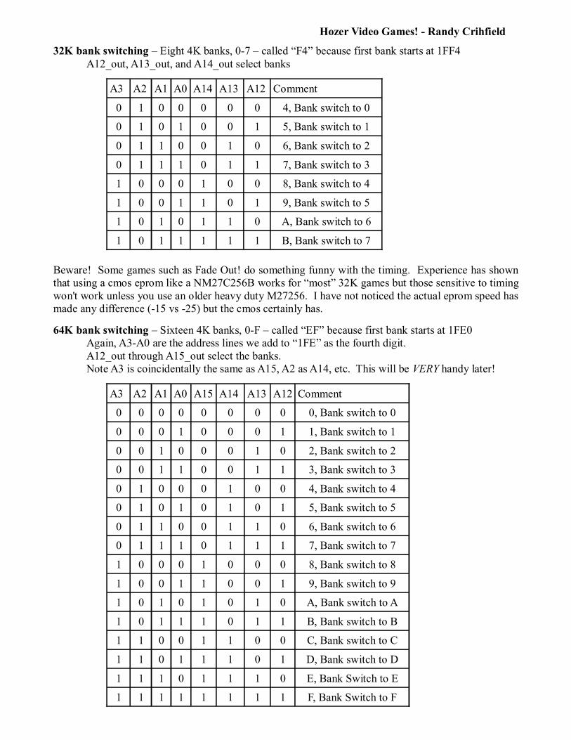
32K bank switching � Eight 4K banks, 0-7 � called �F4� because first bank starts at 1FF4A12_out, A13_out, and A14_out select banks
A3 A2 A1 A0 A14 A13 A12 Comment
0 1 0 0 0 0 0 4, Bank switch to 0
0 1 0 1 0 0 1 5, Bank switch to 1
0 1 1 0 0 1 0 6, Bank switch to 2
0 1 1 1 0 1 1 7, Bank switch to 3
1 0 0 0 1 0 0 8, Bank switch to 4
1 0 0 1 1 0 1 9, Bank switch to 5
1 0 1 0 1 1 0 A, Bank switch to 6
1 0 1 1 1 1 1 B, Bank switch to 7
Beware! Some games such as Fade Out! do something funny with the timing. Experience has shown that using a cmos eprom like a NM27C256B works for �most� 32K games but those sensitive to timing won't work unless you use an older heavy duty M27256. I have not noticed the actual eprom speed has made any difference (-15 vs -25) but the cmos certainly has.
64K bank switching � Sixteen 4K banks, 0-F � called �EF� because first bank starts at 1FE0Again, A3-A0 are the address lines we add to �1FE� as the fourth digit.A12_out through A15_out select the banks.Note A3 is coincidentally the same as A15, A2 as A14, etc. This will be VERY handy later!
A3 A2 A1 A0 A15 A14 A13 A12 Comment
0 0 0 0 0 0 0 0 0, Bank switch to 0
0 0 0 1 0 0 0 1 1, Bank switch to 1
0 0 1 0 0 0 1 0 2, Bank switch to 2
0 0 1 1 0 0 1 1 3, Bank switch to 3
0 1 0 0 0 1 0 0 4, Bank switch to 4
0 1 0 1 0 1 0 1 5, Bank switch to 5
0 1 1 0 0 1 1 0 6, Bank switch to 6
0 1 1 1 0 1 1 1 7, Bank switch to 7
1 0 0 0 1 0 0 0 8, Bank switch to 8
1 0 0 1 1 0 0 1 9, Bank switch to 9
1 0 1 0 1 0 1 0 A, Bank switch to A
1 0 1 1 1 0 1 1 B, Bank switch to B
1 1 0 0 1 1 0 0 C, Bank switch to C
1 1 0 1 1 1 0 1 D, Bank switch to D
1 1 1 0 1 1 1 0 E, Bank Switch to E
1 1 1 1 1 1 1 1 F, Bank Switch to F

Hozer Video Games! - Randy Crihfield
So you want to make a 64K game...
That is not a long jump from here but unlike the 32K �cut a trace and move the wire� simple approach it is a bit more difficult. The problem is you have a new address line on the 27512, pin 1, which means you need another output line on the GAL. No problem � except there are none left free!!! So we have to get a little creative. Instead of two loops for the clock we need to reduce it to just one. This ends up being good news in the end.
Here are the steps.
1. Cut eprom pin 27 free just as we did for the 32K board (lower right arrow)2. Cut eprom pin 1 free in the same way (upper right arrow)3. Tricky cut #1 � cut GAL pin 11 free from where it attaches to the cap (middle arrow)4. Tricky cut #2 � cut the trace between GAL pin 1 and GAL pin 21 (left arrow)5. The GAL programming makes all the difference, more on that later....
OK so obviously we're getting a little ugly with the board, but just a little. You are going to end up with two additional jumper wires on the board, three total:
1. GAL pin 19 jumps to eprom pin 27 (just as it did for the 32K board)2. GAL pin 1 now is tied directly to the cap where GAL pin 11 used to be3. GAL pin 21 jumps to eprom pin 1 (our new A15)
See, not so bad. On the board there is an extra solder hole beside the cap which is perfect for attaching the wire to GAL pin 1, which is handy. This leaves us with GAL pin 11 not being used. Unfortunately on a GAL 20v8 this is only an input, but if you swap a GAL 22v10 you could jump a couple lines around and the extra pin would now an input/output, which means if you want to make a 128K game you can do it. However it STILL requires a whole new board, because the 128K eprom is going to have 32 legs in its package not 28, never mind jumping the pin around would require 2 more jumpers. Ugly! But that's OK, at least we know now HOW to do it, what the wiring will take, etc. Good news there (and besides I have a MUCH better idea...)

Hozer Video Games! - Randy Crihfield
By the way shortening the clock to one loop works for me with 8K, 16K, 32K, etc as well. I am not sure why Chris went with the 2.2K resistor and two loops, but it is easy to work around. I suppose he never intended this board to ever be pushed to its limits in this way, back in 1999! As it is designed it works just fine with the lower than 64K sizes (all the way down to 2K, truthfully) so I am sure not complaining.
Finally, I said �The GAL programming makes all the difference� and here is what I mean by that. My goal was to make a 64K game � ANY 64K game. I do this for a hobby and the challenge was there. As it is, my updated work should allow for all types of 64K games that don't require any RAM (except Sara chips � I can make 8/16/32/64K games that use the Sara chip now). The �progressive� bank switching is the easiest � for those in the know you see the GAL programming would be as easy as �A12 = A0, A13=A1, A14=A2, and A15=A3� which is child's play to program. Unfortunately .. no one uses this style of bank switching as far as I know. Instead it is always some custom job.
The wiring I have works for any 64K but for example doing the Megaboy the GAL had to know to �figure out what bank you are on and increment by one� which is how the Megaboy does its bank switching. This wasn't hard but it won't work for say Turbo or Stella's Stocking, which required yet a different GAL programming to be done. Sigh. In other words, no standards between developers. Sometimes that is by design, because some people are interested in MONEY not community.
However, I also figured out along the way that I could w/o a lot of grief reprogram the GAL to make Tigervision games and Activsion games. I haven't tried Parker Brothers yet but pretty much anything that doesn't use RAM should be doable. Best of all, the game can be made with cheap parts and the end price of the cart can be kept low for everyone. Excellent!
Let's program a GAL!
Ok so what is going on behind the scenes? Let's use the F8 example to learn how to program a GAL. This will require you hunt down and download EQN2JED.exe which is in truth a set of three files, that one, JED2EQN.exe, and device.lib. These are old DOS programs but work great, however any filenames must be 8 chars or less, etc. Now using your favorite editor create Atari_F8.eqn and create this:
Remember, we are interested in 1FF8 and 1FF9. That would be 1111111111000 and 1111111111001. The difference is that final bit, which here is in the A0 location (remember, it goes A12 down to A0, 13 bits right? More later, bear with me...)
Well, then when we are in the first bank A0 equals 0 and in the second bank A0 is 1. So all we need to do is watch for the first 12 bits to match up, the 111111111100 part. That is what o15 is. When those 12 bits match, we simply bankswitch to the value of A0, either bank 0 or bank 1.
Remember the PAL mapping? A0 maps to pin 9, so note ro22 (which is the eprom enabler for A12out) is set to i9. That only happens when o15 is true.
; Atari F8 programming
chip Atari_F8 GAL20V8
CLK=1 i2=2 i3=3 i4=4 i5=5 i6=6 i7=7 i8=8 i9=9 i10=10 i11=11 GND=12 /OE=13 i14=14 o15=15 o16=16 f17=17 f18=18 f19=19 ro20=20 o21=21 ro22=22 i23=23 VCC=24
equations
ro22 := i9 ro22.oe = OE o21 = i11 o21.oe = vcc ro20 = gnd ro20.oe = gndf19 = gnd f19.oe = gnd f18 = gnd f18.oe = gnd f17 = gnd f17.oe = gnd o16 = /i8 o16.oe = vcc o15 = i8 * i5 * i7 * i4 * i3 * i23 * i2 * i10 * i14 * i6 * /f18 * /f17o15.oe = vcc

Hozer Video Games! - Randy Crihfield
Ok so reusing this table from above, let's add the GAL pins:
A12 A11 A10 A9 A8 A7 A6 A5 A0 A3 A2 A1 A0 Address Enabled
1 1 1 1 1 1 1 1 1 1 0 0 0 1 F F 8
1 1 1 1 1 1 1 1 1 1 0 0 1 1 F F 9
i8 i5 i7 i4 i3 i23 i2 i10 i14 i6 f18 f17 i9 GAL pins
.and suddenly o15 makes more sense! By the way when you WANT a value to be 0 you �not� it by using a / in front of it. The �*� means �and�. It is Boolean math = when they are all true you have a match.
So when this is all true you bank switch:
o15= i8 * i5 * i7 * i4 * i3 * i23 * i2 * i10 * i14 * i6 * /f18 * /f17
A12=1, A11=1, �, A3=1, NOT A2=0, NOT A1=0
(NOT FALSE means TRUE, right? That's �NOT 0� in a binary world)
Anyhow, when these are all true 015 becomes true and then ro22 is set to whatever A0 happens to be. If the call was 1111111111001 (1FF9) then A0, the last bit, was a 1 and you bank switch to the second bank. Easy. How easy? Consider this, suppose we change just these two lines:
ro22 := i2o15 = /i8 * /i5 * /i7 * i4 * /i3 * /i23 * /i2 * i10 * /i14 * /i6 * /f18 * /f17 * /i9 + /i8 * /i5 * /i7 * i4 * /i3 * /i23 * i2 * /i10 * /i14 * /i6 * /f18 * /f17 * /i9
What have we done? Well, o15 now only becomes true when these two possible address values were called: 0001000100000 = 0220 OR 000100100000 = 0240. Follow that? So if the address called matches the first one, 0220, OR it matches the second one, 0240, you use the value of i2 (A6) to select the bank. Congratulations, you now have a GAL that can be used to make Gingerbread Man (which uses the UA bank switching style!)
Probably too late to have explained this, but all the addresses use 13 lines, A12 down to A0. That means in HEX it is 4 sets (pretend 3 leading 0's). Four groups of 4.
If you don't know Hex, four bits resolve to a numerical value from 0 (0000) to F (1111). Why F? Because there is no �10�. You count 0, 1, 2, 3, 4, 5, 6, 7, 8, 9, A, B, C, D, E, F. It makes sense, look at some more examples. 1 is 0001. But 2 is 0010. That mean there is �one 2�. The spots are 8, 4, 2, and 1. So to show 10, or A, that is 8 and 2, so 1010. One 8 and one 2.
Here's the whole thing to make it VERY clear:
0 0000 4 0100 8 1000 C 11001 0001 5 0101 9 1001 D 11012 0010 6 0110 A 1010 E 11103 0011 7 0111 B 1011 F 1111
So 1FF8 resolves to 0001 1111 1111 1000 and we drop the leading 0's just as you wouldn't say there were 0005 apples, you'd say there were 5. Got it?
Oh � to create the jdec file to program your gal with execute this command: EQN2JED filename.eqn

Hozer Video Games! - Randy Crihfield
The Program dumps...
Atari F8/F6 - 8K/16K JDEC file, in EQN format.
Note for o15=i2 (and so forth) the SECOND line of the equation is only used when tied to +5 volts.
That is, the portion i2 through i14 handle 8K, while the second portion, + i2 through i14 only becomes viable when GAL pin 19 is tied to +5 volts which allows for the 16K bank switching.
If GAL pin 19 is tied to ground, you essentially multiply by 0 and it is eliminated. This means for an 8K cart, where pin 19 IS tied to ground, you only get bank switching in the range 1ff8 and 1ff9, but for a 16K one you get 1ff6, 1ff7, 1ff8, and 1ff9
Neat you can do 8K and 16K with one GAL!
0840 Econobanking � 8K JDEC file, in EQN format.
One of the most simple because the switching just watches for A12 to be 0 and A11 to be 1. If that's true then the bank switch occurs, which uses the value in A6 to decide if it is in bank 0 or 1.
No jumper are required on the board at all, just the Eprom and the GAL.
It might be worth noting that ALL of these bank switches, every one of them, can be implemented on a board using a Sara chip. No magic involved to get the extra memory to appear. If one programs using any of these bank switch styles and wants to leverage the Sara chip it should be easy. Not that anyone does...
CLK=1 i2=2 i3=3 i4=4 i5=5 i6=6 i7=7 i8=8 i9=9 i10=10 i11=11 GND=12 /OE=13 i14=14 o15=15 o16=16 f17=17 f18=18 f19=19 ro20=20 o21=21 ro22=22 i23=23 VCC=24
equations
ro22 := i9 ro22.oe = OE o21 = i11 o21.oe = vcc ro20 := /f17 ro20.oe = OE
f19 = gnd f19.oe = gnd f18 = gnd f18.oe = gnd f17 = gnd f17.oe = gnd o16 = /i8 o16.oe = vcc
o15 =i8 * i5 * i7 * i4 * i3 * i23 * i2 * i10 * i14 * i6 * /f18 * /f17 + i8 * i5 * i7 * i4 * i3 * i23 * i2 * i10 * i14 * /i6 * f18 * f17 * f19 o15.oe = vcc
CLK=1 i2=2 i3=3 i4=4 i5=5 i6=6 i7=7 i8=8 i9=9 i10=10 i11=11 GND=12 /OE=13 i14=14 o15=15 o16=16 f17=17 f18=18 f19=19 f20=20 o21=21 ro22=22 i23=23 VCC=24
@ues 0000000000000000 @ptd unused
equations
ro22 := i2 ro22.oe = OE o21 = i11 o21.oe = vcc f20 = gnd f20.oe = gnd f19 = gnd
f19.oe = gnd f18 = gnd f18.oe = gnd f17 = gnd f17.oe = gnd o16 = /i8 o16.oe = vcc o15 = /i8 * i5
o15.oe = vcc
Hozer Video Games! - Randy Crihfield
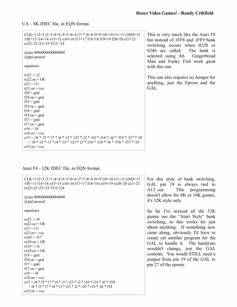
UA � 8K JDEC file, in EQN format.
This is very much like the Atari F8 but instead of 1FF8 and 1FF9 bank switching occurs when 0220 or 0240 are called. The bank is selected using A6. Gingerbread Man and Funky Fish work great with this one.
This one also requires no Jumper for anything, just the Eprom and the GAL.
Atari F4 - 32K JDEC file, in EQN format.
For this style of bank switching, GAL pin 19 is always tied to A13_out. This programming doesn't allow for 8K or 16K games, it's 32K style only.
So far I've noticed all the 32K games use the �Atari Style� bank switching, so this works for just about anything. If something new came along, obviously I'd have to create yet another program for the GAL to handle it. The hardware wouldn't change, just the GAL contents. You would STILL need a jumper from pin 19 of the GAL to pin 27 of the eprom.
CLK=1 i2=2 i3=3 i4=4 i5=5 i6=6 i7=7 i8=8 i9=9 i10=10 i11=11 GND=12 /OE=13 i14=14 o15=15 o16=16 f17=17 f18=18 ro19=19 ro20=20 o21=21 ro22=22 i23=23 VCC=24
@ues 0000000000000000 @ptd unused
equations
ro22 := i9 ro22.oe = OE o21 = i11
o21.oe = vcc ro20 := f17 ro20.oe = OE ro19 := i6 ro19.oe = OE f18 = gnd f18.oe = gnd f17 = gnd
f17.oe = gnd o16 = /i8 o16.oe = vcc o15 = i8 * i5 * i7 * i4 * i3 * i23 * i2 * i10 * i14 * i6 * /f18 + i8 * i5 * i7 * i4 * i3 * i23 * i2 * i10 * i14 * /i6 * f18 o15.oe = vcc
CLK=1 i2=2 i3=3 i4=4 i5=5 i6=6 i7=7 i8=8 i9=9 i10=10 i11=11 GND=12 /OE=13 i14=14 o15=15 o16=16 f17=17 f18=18 f19=19 f20=20 o21=21 ro22=22 i23=23 VCC=24
@ues 0000000000000000 @ptd unused
equations
ro22 := i2 ro22.oe = OE o21 = i11 o21.oe = vcc f20 = gnd f20.oe = gnd f19 = gnd
f19.oe = gnd f18 = gnd f18.oe = gnd f17 = gnd f17.oe = gnd o16 = /i8 o16.oe = vcc o15 = /i8 * /i5 * /i7 * i4 * /i3 * /i23 * /i2 * i10 * /i14 * /i6 * /f18 * /f17 * /i9
+ /i8 * /i5 * /i7 * i4 * /i3 * /i23 * i2 * /i10 * /i14 * /i6 * /f18 * /f17 * /i9 o15.oe = vcc
Hozer Video Games! - Randy Crihfield
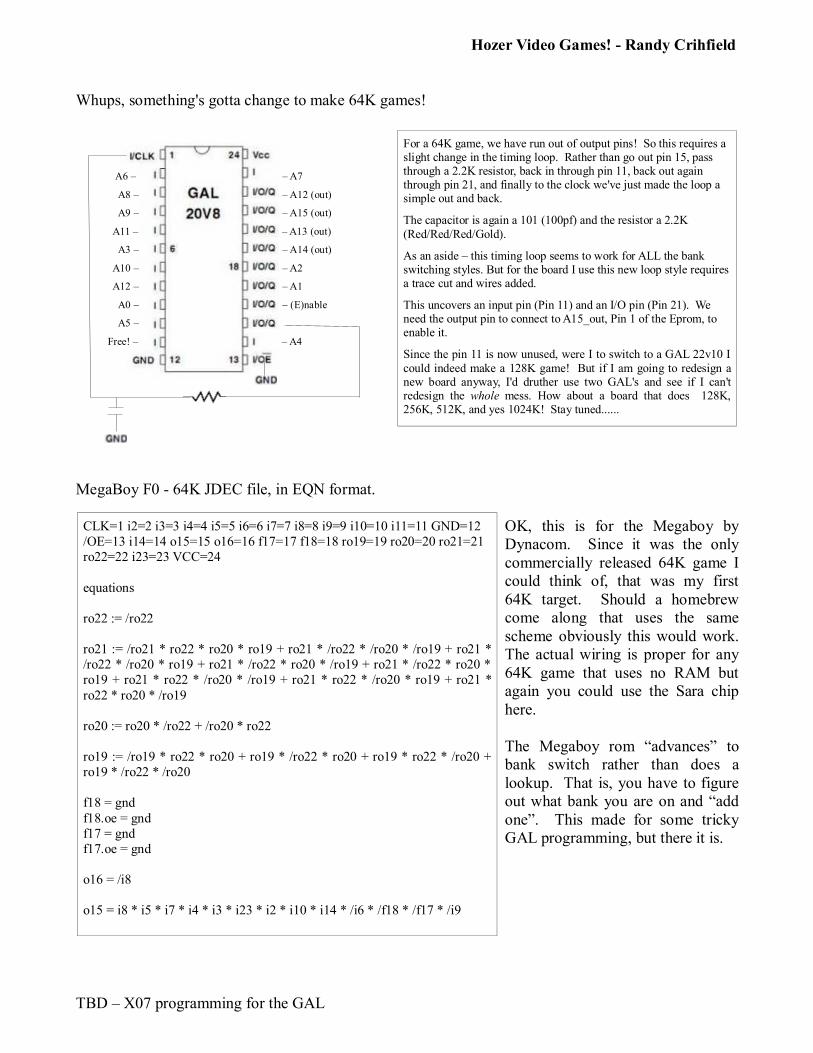
Whups, something's gotta change to make 64K games!
A6 � � A7
A8 � � A12 (out)
A9 � � A15 (out)
A11 � � A13 (out)
A3 � � A14 (out)
A10 � � A2
A12 � � A1
A0 � � (E)nable
A5 �
Free! � � A4
MegaBoy F0 - 64K JDEC file, in EQN format.
OK, this is for the Megaboy by Dynacom. Since it was the only commercially released 64K game I could think of, that was my first 64K target. Should a homebrew come along that uses the same scheme obviously this would work. The actual wiring is proper for any 64K game that uses no RAM but again you could use the Sara chip here.
The Megaboy rom �advances� to bank switch rather than does a lookup. That is, you have to figure out what bank you are on and �add one�. This made for some tricky GAL programming, but there it is.
TBD � X07 programming for the GAL
CLK=1 i2=2 i3=3 i4=4 i5=5 i6=6 i7=7 i8=8 i9=9 i10=10 i11=11 GND=12 /OE=13 i14=14 o15=15 o16=16 f17=17 f18=18 ro19=19 ro20=20 ro21=21 ro22=22 i23=23 VCC=24
equations
ro22 := /ro22
ro21 := /ro21 * ro22 * ro20 * ro19 + ro21 * /ro22 * /ro20 * /ro19 + ro21 * /ro22 * /ro20 * ro19 + ro21 * /ro22 * ro20 * /ro19 + ro21 * /ro22 * ro20 * ro19 + ro21 * ro22 * /ro20 * /ro19 + ro21 * ro22 * /ro20 * ro19 + ro21 *
ro22 * ro20 * /ro19
ro20 := ro20 * /ro22 + /ro20 * ro22
ro19 := /ro19 * ro22 * ro20 + ro19 * /ro22 * ro20 + ro19 * ro22 * /ro20 + ro19 * /ro22 * /ro20
f18 = gnd
f18.oe = gnd f17 = gnd f17.oe = gnd
o16 = /i8
o15 = i8 * i5 * i7 * i4 * i3 * i23 * i2 * i10 * i14 * /i6 * /f18 * /f17 * /i9
For a 64K game, we have run out of output pins! So this requires a slight change in the timing loop. Rather than go out pin 15, pass through a 2.2K resistor, back in through pin 11, back out again through pin 21, and finally to the clock we've just made the loop a simple out and back.
The capacitor is again a 101 (100pf) and the resistor a 2.2K (Red/Red/Red/Gold).
As an aside � this timing loop seems to work for ALL the bank switching styles. But for the board I use this new loop style requires a trace cut and wires added.
This uncovers an input pin (Pin 11) and an I/O pin (Pin 21). We need the output pin to connect to A15_out, Pin 1 of the Eprom, to enable it.
Since the pin 11 is now unused, were I to switch to a GAL 22v10 I could indeed make a 128K game! But if I am going to redesign a new board anyway, I'd druther use two GAL's and see if I can't redesign the whole mess. How about a board that does 128K, 256K, 512K, and yes 1024K! Stay tuned......
Hozer Video Games! - Randy Crihfield
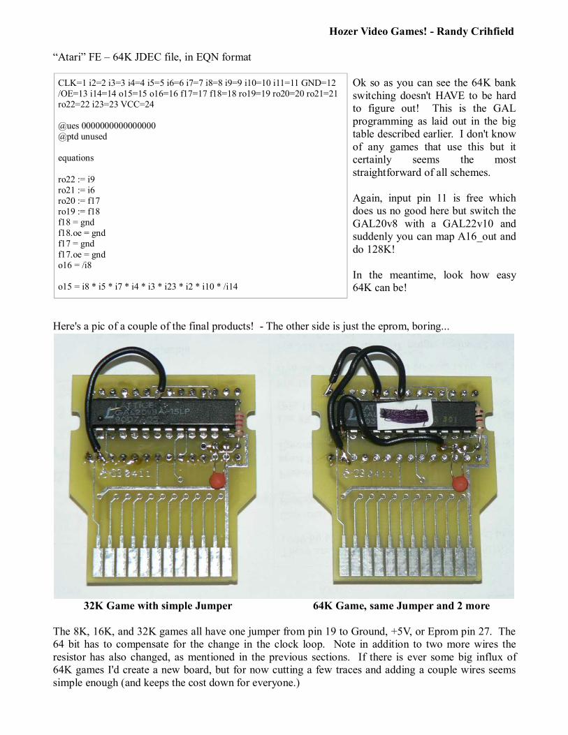
�Atari� FE � 64K JDEC file, in EQN format
Ok so as you can see the 64K bank switching doesn't HAVE to be hard to figure out! This is the GAL programming as laid out in the big table described earlier. I don't know of any games that use this but it certainly seems the most straightforward of all schemes.
Again, input pin 11 is free which does us no good here but switch the GAL20v8 with a GAL22v10 and suddenly you can map A16_out and do 128K!
In the meantime, look how easy 64K can be!
Here's a pic of a couple of the final products! - The other side is just the eprom, boring...
32K Game with simple Jumper 64K Game, same Jumper and 2 more
The 8K, 16K, and 32K games all have one jumper from pin 19 to Ground, +5V, or Eprom pin 27. The 64 bit has to compensate for the change in the clock loop. Note in addition to two more wires the resistor has also changed, as mentioned in the previous sections. If there is ever some big influx of 64K games I'd create a new board, but for now cutting a few traces and adding a couple wires seems simple enough (and keeps the cost down for everyone.)
CLK=1 i2=2 i3=3 i4=4 i5=5 i6=6 i7=7 i8=8 i9=9 i10=10 i11=11 GND=12 /OE=13 i14=14 o15=15 o16=16 f17=17 f18=18 ro19=19 ro20=20 ro21=21 ro22=22 i23=23 VCC=24
@ues 0000000000000000 @ptd unused
equations
ro22 := i9 ro21 := i6 ro20 := f17 ro19 := f18 f18 = gnd f18.oe = gnd f17 = gnd
f17.oe = gnd o16 = /i8
o15 = i8 * i5 * i7 * i4 * i3 * i23 * i2 * i10 * /i14
Hozer Video Games! - Randy Crihfield
So you are greedy and you want a 128K, 256K, 512K, and yes even a 1MB game! Well, yep, it is more than possible it's been done! Snailsoft made me up a demo using the inefficient Super Banking style bank switching and voila. Now let's see someone actually do something amazing with it, I hope!
There are two GAL's. One controls the ROM enable for A12, A13, A14 and A15. Yes, the 64K cart as described earlier. The SECOND GAL controls the ROM enable for A16, A17, A18, and A19. The GALs are also tied together at pin 23. It really isn't so wild if you think about it � If you want to make a 128K game you use a 22v10 and enable the pin 23 as if it were going to the ROM. The second GAL watches pin 23 and if its enabled passes it along to A16. Poof.
OR! You use two 20v8 GALs and both independently watch for bankswitching and when it does flip their respective output pins off and on. That's how the Super Banking works, just a simple extension of the 0840 pumped up. What this means is you can do all sorts of things. One could do incremental bank switching (where the 65th call tickles pin 23 and the second GAL increments, etc) Or you could use the EF �style� for both, but for the second use something like the DF range. You could mix and match � using EF style for one and F0 style for the other. Some of these solutions wouldn't even need anything more complicated than a pair of 20v8. Since the two GALS are programmed independently, you can do almost anything.
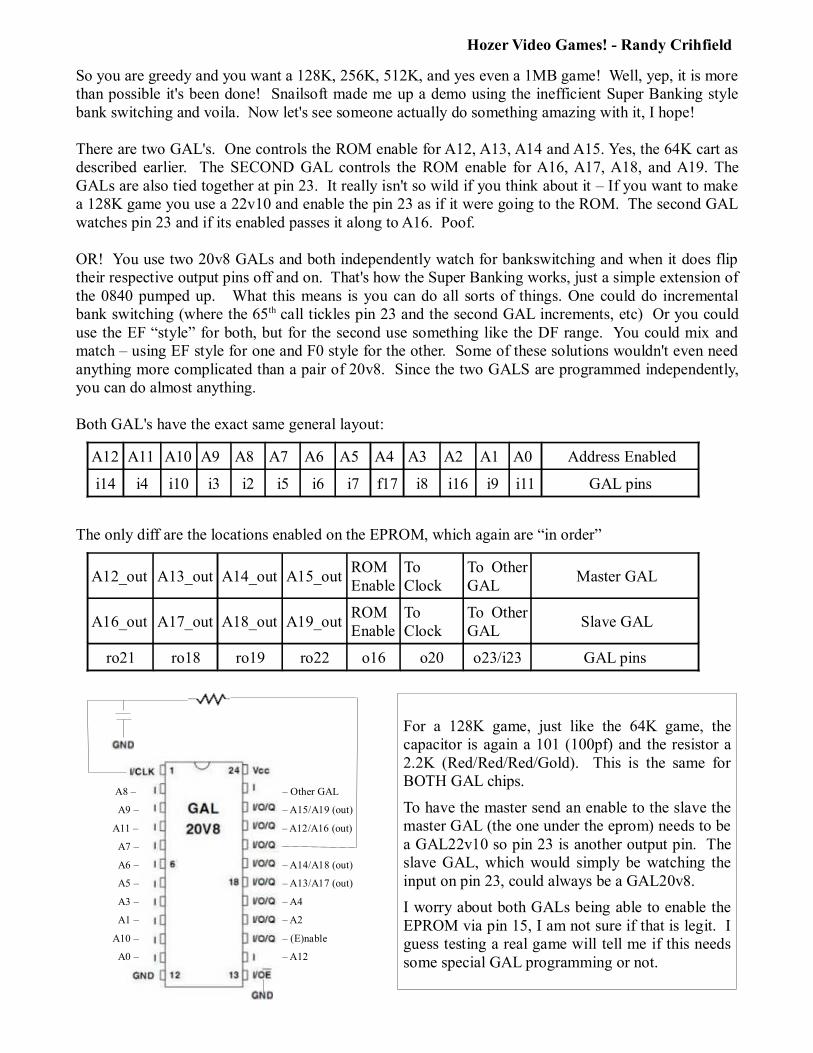
Both GAL's have the exact same general layout:
A12 A11 A10 A9 A8 A7 A6 A5 A4 A3 A2 A1 A0 Address Enabled
i14 i4 i10 i3 i2 i5 i6 i7 f17 i8 i16 i9 i11 GAL pins
The only diff are the locations enabled on the EPROM, which again are �in order�
A12_out A13_out A14_out A15_outROM Enable
To Clock
To Other GAL
Master GAL
A16_out A17_out A18_out A19_outROM Enable
To Clock
To Other GAL
Slave GAL
ro21 ro18 ro19 ro22 o16 o20 o23/i23 GAL pins
A8 � � Other GAL
A9 � � A15/A19 (out)
A11 � � A12/A16 (out)
A7 �
A6 � � A14/A18 (out)
A5 � � A13/A17 (out)
A3 � � A4
A1 � � A2
A10 � � (E)nable
A0 � � A12
For a 128K game, just like the 64K game, the capacitor is again a 101 (100pf) and the resistor a 2.2K (Red/Red/Red/Gold). This is the same for BOTH GAL chips.
To have the master send an enable to the slave the master GAL (the one under the eprom) needs to be a GAL22v10 so pin 23 is another output pin. The slave GAL, which would simply be watching the input on pin 23, could always be a GAL20v8.
I worry about both GALs being able to enable the EPROM via pin 15, I am not sure if that is legit. I guess testing a real game will tell me if this needs some special GAL programming or not.

Hozer Video Games! - Randy Crihfield
Bonus, if you made a 64K Super Banking image you could easily use the same board because the master GAL does exactly that � handles 64K. You could in truth program it with any style of 64K bank switching you wanted as long as you keep the output pins correctly lined up in your GAL programming. I'd be glad to help there if you need it.
Here's the eqn file for the 1MB image
This is exactly the same logic for the base image, except the comment about A16_out etc would read it is for A_12_out, etc. The actual jdec code is spot on the same.
For a 512mb game, the ro22 which is A19_out would not be used, so it and its output enable would be set to ground. That means instead of what you see here, it would change to
ro22 = gndro22.oe = gnd
and for 256 the ro19 would join it, and for 128 the ro18 would join them! It's as easy as that folks.
CLK=1 i2=2 i3=3 i4=4 i5=5 i6=6 i7=7 i8=8 i9=9 i10=10 i11=11 GND=12 /OE=13 i14=14 o15=15 o16=16 f17=17 ro18=18 ro19=19 o20=20 ro21=21 ro22=22 i23=23 VCC=24
@ues 0000000000000000 @ptd unused
equations
; these ALL matter, toggle A16_out, A17_out, A18_out, and A19_out ro21 := f17 ro21.oe = OE ro18 := i7 ro18.oe = OE ro19 := i6 ro19.oe = OE
ro22 := i5 ro22.oe = OE
; hande rest of output lines /f17 = gnd f17.oe = gnd /o16 = gnd o16.oe = gnd
o15 = /i14 o15.oe = vcc
; This triggers the bankswitch, when A12=0 and A11=1 o20 = /i14 * i4

Hozer Video Games! - Randy Crihfield
But wait there's more! Here's a snapshot of the original 32K boards I have, in a drawer unused.
And just suppose.....
you have some of these old Chris Wilkson 32K boards laying around? The ones he made up for Marble Craze, etc.
Well guess what chicken butt, not only is Chris a genius but he's a man ahead of his time.
The board, drawn up back in 2000, is ready to go for a 2K, 4K, 8K, 16K, 32K, AND 64K game just as it was originally made! Chris left GAL pin 15 free � and put a solder hole next to it for a wire. A few mm's away there is another solder hole � connected to pin 1 of the eprom! You add a jumper here, cut pin 1 loose from the 5V connection it normally has, and voila you have a tidy 64K board ready to rock.
The GAL programming map is below. All you have to do to try this for example is take the 64K FE programming from above, throw away the gnd statements, remap the pins to the right places and away you go! I did it, and it works.
Here are the pins:
Old 1 clk i2 i3 i4 i5 i6 i7 i8 i9 i10 i11 12 GND i13 i14 o15 o16 f17 f18 ro19 ro20 ro21 ro22 i23 24 5V
New 1 clk i23 i3 i4 i5 i18 i7 i11 i10 i19 i14 12 GND i13 i6 o16 o17 i9 i8 ro21 ro20 ro15 ro22 i2 24 5V
And here's the eqn for the 64K �Other� Chris Wilkson 32K board:
Funny isn't it, how back in 2000 we could have had 64K games and widespread 32K ones, but because �some people� wanted to hold a tight monopoly on the information so they could make money they never shared even these simple things?
That's why I give this info away for FREE so anyone can make any game they want, w/o having to cough up a boatload of money to line someone's pockets....
CLK=1 i2=2 i3=3 i4=4 i5=5 i6=6 i7=7 i8=8 i9=9 i10=10 i11=11 GND=12 /OE=13 i14=14 ro15=15 o16=16 o17=17 i18=18 i19=19 ro20=20 ro21=21 ro22=22 i23=23 VCC=24
@ues 0000000000000000 @ptd unused
equations
ro22 := i10 ro15 := i18 ro20 := i9 ro21 := i8
o17 = /i11
o16 = i11 * i5 * i7 * i4 * i3 * i2 * i23 * i19 * /i6

Hozer Video Games! - Randy Crihfield
Which is too bad. If they had talked nicely to Chris they would have known better what they were doing.
For instance, now suppose you have a couple of these blue jobbers. I see them often enough that I have a good sized drawer of them. Folks buy them, they don't work, and then they ship them to me to make work.
These guys cannot easily do 64K, and it's a crying shame. There are two pins not connected on the GAL, 11 and 14, which are both input only pins. So there's nowhere handy to hook up A15_out. I mean you COULD if you were to hack the board up but why did it come to that? You could also make
it work using a GAL 22v10, but you still have to work the thing over. The board was soooo close to being a pretty 64K board. Sigh. But maybe we can make it sit up and dance for us. Of course the folks who worked up this �competitor� board wouldn't give us the GAL's jdec file.
Yet I think we can figure it out! <Smile!> First here are the �comparative� pins to our old friend GAL20v8 using Chris' original workhorse 8/16K board, let's try for the simple 64K EF programming. That Chris is amazing, and he also shared his work with others...
.Here are the pins laying our old and their new side by side:
Old 1 clk i2 i3 i4 i5 i6 i7 i8 i9 i10 i11 12 GND i13 i14 o15 o16 f17 f18 ro19 ro20 ro21 ro22 i23 24 5V
New 1 clk i9 i17 i18 i19 i6 i2 i23 i3 i8 i11 12 GND i13 i7 o22 o21 i4 i5 ro15 ro16 ro14 ro20 i10 24 5V
What's fishy here? Well ro14 is! Because they never thought past the end of 32K they �wasted� the output pins by burying them. The easiest thing to do to fix this is to change GALs, so we could swap that �input only� pin 14 of the GAL20v8 with a i/o pin 14 which is what it is on a GAL22v10.
And here's the eqn that allows the 32K �competitor� board to do 64K, using a GAL22v10. Does it work you ask? You bet, I made someone a MegaBoy cart already:
So my suggestion � bend up pins 14 on the 22v10 and 1 on the eprom. Solder the chips in place otherwise. Then jumper a wire from the two bent up pins. Voila, your 32K board you bought from my �competitor� that they won't tell you diddly squat about how to program you have turned into a 64K game.
I mean, if you wanted the 8K, 16K, or 32K programming I could give you that too but I think after reading this you could probably make anything you want without too much trouble....
CLK=1 i2=2 i3=3 i4=4 i5=5 i6=6 i7=7 i8=8 i9=9 i10=10 i11=11 GND=12 /OE=13 ro14=14 ro15=15 ro16=16 i17=17 i18=18 i19=19 ro20=20 o21=21 o22=22 i23=23 VCC=24
@ues 0000000000000000 @ptd unused
equations
ro20 := i3 ro14 := i6
ro16 := i4 ro15 := i5
o21 = /i23
o22 = i23 * i19 * i2 * i18 * i17 * i10 * i9 * i8 * /i7