
How To Use A Transit Final2
16
HOW TO USE A TRANSIT TABLE OF CONTENTS Transit History and Description page 3 Transit Setup page 4 Leveling Screws page 4 Checking Transit Accuracy page 6 Adjusting the Level Tube page 7 Measuring a Horizontal Angle page 11 Measuring Vertical Angles page 11 Reading the Vernier (figures A and B) page 12 As Stated in the Berger Instruments PDF: Setting Points in Line page 12 Plumbing page 13 Slopes and Rates of Grades page 14 Grade Line for a Sewer page 14 Figure 1A - Positioning and Leveling the Instrument page 8 Figure 2A - Move Transit and Mark Rods page 8
-
Upload
americanmillwright -
Category
Documents
-
view
114 -
download
4
description
Transits
Transcript of How To Use A Transit Final2

HOW TO USE A TRANSIT
TABLE OF CONTENTS
Transit History and Description page 3
Transit Setup page 4
Leveling Screws page 4
Checking Transit Accuracy page 6
Adjusting the Level Tube page 7
Measuring a Horizontal Angle page 11
Measuring Vertical Angles page 11
Reading the Vernier (figures A and B) page 12
As Stated in the Berger Instruments PDF:
Setting Points in Line page 12
Plumbing page 13
Slopes and Rates of Grades page 14
Grade Line for a Sewer page 14
Figure 1A - Positioning and Leveling the Instrument page 8
Figure 2A - Move Transit and Mark Rods page 8

Figure 3 - Adjusting the Level Tube page 7
Figure 4 - Adjusting the Horizontal Cross-Hair page 8
Figure 5A - Level plane below both elevations page 9
Figure 5B - Level plane is between both elevations page 9
As Stated in the Berger Instruments PDF:
Figure 14 - Points on a property boundary page 11
Figure 15 - Plumbing a vertical column page 13
Figure 16 - Definitions of grades and slopes page 14
Figure 17 - Grade line for a sewer page 14
Figure 18 - Typical layout for sewer batter boards page 14
Figure 19 - Offset Grade Stakes for a 12 foot driveway page 15

Transit History and Description:
The notable Philadelphia manufacturer, William J. Young, was the self-proclaimed, and generally accepted, inventor of the first American transit in the year 1831. Young's new transit enabled the perpetuation of a straight line by means of turning, or "transiting" the telescope on its horizontal axis. The primary purpose of a transit is to measure horizontal and vertical angles. The theodolite serves the same purpose as the transit, and they have many similar features. The major difference between a transit and a theodolite is that a transit features measuring circles which are constructed only of glass and are observed through magnifying optics to increase the accuracy of angular readings. Circles, one vertical and one horizontal, are used for these measurements. The lower transit plate carries the graduated circle and the upper transit plate carries the verniers for reading the angles on this circle.The vertical circle, fixed to a horizontal axis that is part of, and at 90 degrees to a telescope, lets the telescope rotate in a vertical plane. The alidade, or the framework that supports the telescope axis, has a vertical axis (spindle) attached to its base, which allows the alidade to rotate with respect to the horizontal circle. Level vials, attached to the alidade, are used to make the spindle vertical (in line with gravity), so that measurement of horizontal angles can be measured. A level vial is also attached to the telescope and provides the gravity index to measure vertical angles.
For leveling the instrument, there are two spirit levels on the upper plate, one parallel and the other at right angles to the horizontal axis. The spirit level that is parallel to the axis is the most important because it controls the position of the horizontal axis of the telescope. In the transit, the leveling is done by means of four (sometimes three) leveling screws. The upper plate usually carries a compass-box with a magnetic needle and a circle graduated to half degrees, so that the transit may also
Transit Definition = A surveying
instrument used to measure horizontal and vertical angles.
Transit Setup
1. Setup tripod so head (TOP PLATE) is about level. This will make leveling the instrument easier. Drive tripod legs into the ground by stepping on each leg.
2. Release horizontal clamp screw and turn instrument until the telescope bubble is directly over a pair of leveling screws.
3. Turn both screws either toward or away from each other. One screw will then be loosened by the same amount that the other is tightened until bubble is level.
NOTE:
THE LEFT THUMB RULE STATES THAT MOVING YOUR LEFT THUMB TO THE LEFT…AS YOU MOVE YOUR RIGHT THUMB TO THE RIGHT…WILL CAUSE THE BUBBLE TO MOVE LEFT. MOVING YOUR LEFT THUMB TO THE RIGHT…WHILE YOUR RIGHT THUMB MOVES TO THE LEFT…WILL CAUSE THE BUBBLE TO MOVE TOWARD THE RIGHT
4. Turn the telescope 90 degrees until over the other set of leveling screws or when you have only three leveling screws then over the third screw and adjust.
5. Repeat the leveling procedure above alternating from one pair of leveling screws to the other until transit is level.
be used as a compass. The lower spindle fits into a socket in the leveling base. This base is provided with a ball-and-socket joint and four leveling screws. Both the upper and lower plates are provided with clamps to hold them in any desired position as well as tangent screws for setting the telescope, or the circles, in an exact position. Under the center of the ball-and-socket joint hangs a short chain to which the plumb-line is attached. The entire head of the instrument can be shifted a fraction of a centimeter
laterally with reference to the tripod and thus can be readily placed exactly over a point on the ground. The horizontal circle is usually graduated either to half-degrees or to 20-minute spaces. The graduations are usually numbered from 0° to 360° by two rows of figures running in opposite directions. In some older transits they are numbered from 0° to 360° in a right-hand direction and, by a second row of figures, from 0° each way to 180°. The transit is usually provided with opposite pairs of verniers. The normal or direct position of the transit is with the upper clamp and its tangent screw nearest the observer and the focusing screw of the telescope on top of the telescope. When the instrument is turned 180° in azimuth from the direct position, and the telescope is inverted (turned about its horizontal axis), it is said to be in the reversed position. This is often spoken of as “plunging” the telescope. If the telescope is provided with a long level tube and a vertical circle or arc, it is called an “Engineer's Transit”, or “Surveyor's Transit”. If it does not have these attachments, it is called a “Plain Transit”.
Transit Setup:
In setting up the transit, first give the tripod sufficient spread to insure steadiness, keeping the plate of the instrument approximately level, the plumb-bob being nearly over the point. Then, if the instrument is so far from the point that it cannot be brought into the correct position by pressing the legs into the ground, the instrument should be lifted bodily and moved so that the plumb-bob is practically over the point. Press the legs firmly into the ground, doing this in such a manner as to gradually bring the plumb-bob accurately over the point. The nuts on the tripod legs should be tight enough so that the legs are just about to fall of their own weight when raised from the ground. If they are loose, the instrument is not rigid. If they are too tight, it is not in a stable condition and may shift any moment.
If the point is on sloping ground, it is often convenient, and
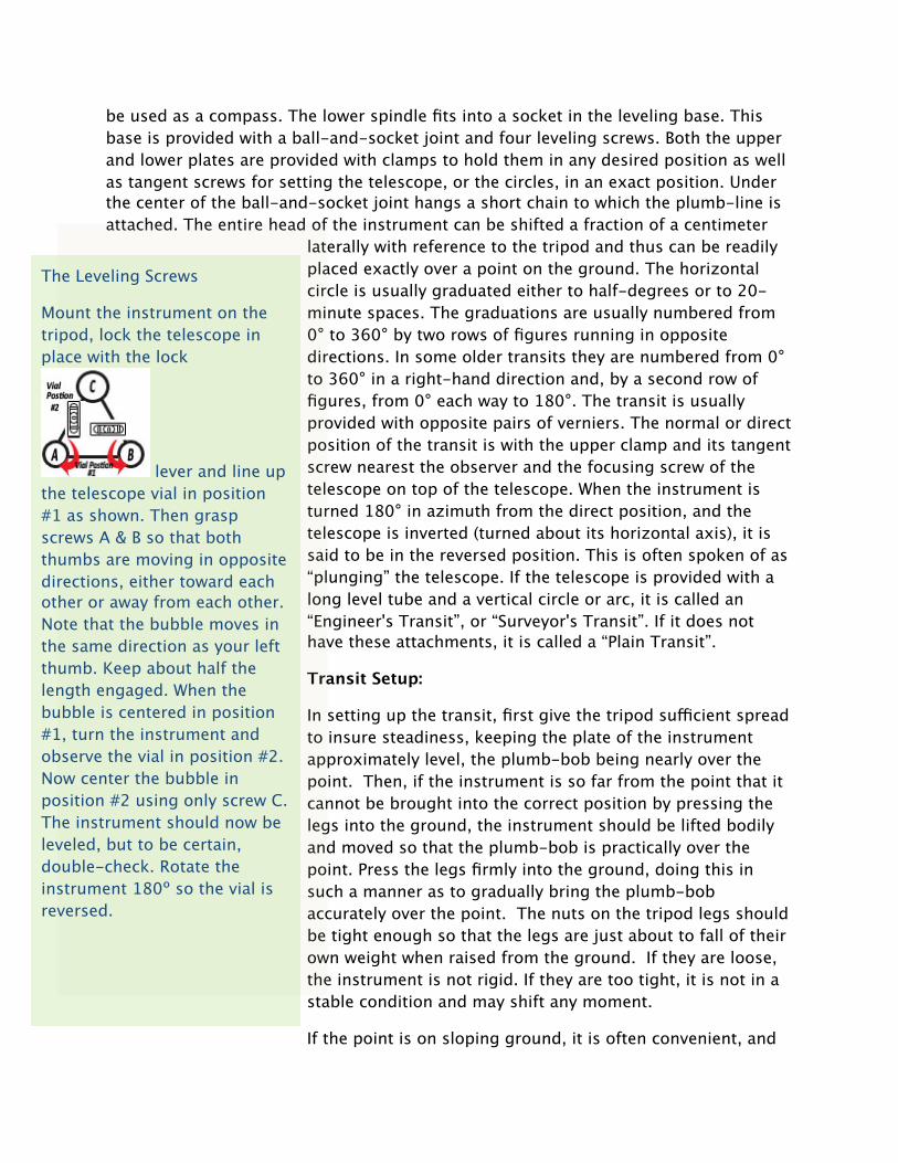
The Leveling Screws
Mount the instrument on the tripod, lock the telescope in place with the lock
lever and line up the telescope vial in position #1 as shown. Then grasp screws A & B so that both thumbs are moving in opposite directions, either toward each other or away from each other. Note that the bubble moves in the same direction as your left thumb. Keep about half the length engaged. When the bubble is centered in position #1, turn the instrument and observe the vial in position #2. Now center the bubble in position #2 using only screw C. The instrument should now be leveled, but to be certain, double-check. Rotate the instrument 180º so the vial is reversed.

insures greater stability, to set two legs downhill and one uphill. When the instrument is over the point, the tripod head can be leveled approximately without moving the instrument away from the point by moving one, sometimes two, of the tripod legs in an arc of a circle about the point. Nothing but practice will make one expert in setting up the transit.
It is desirable to bring the instrument very nearly level by means of the tripod. This is really a saving of time because under ordinary conditions it takes longer to level up by the leveling screws than by the tripod. It also saves time on the next setup to have the leveling screws nearly in their mid position. If the transit is set by means of the tripod, say, within 0.01 or 0.02 ft. of the point, the exact position can be readily reached by means of the shifting head, which may be moved freely after any two adjacent leveling screws are loosened. When the transit has been brought directly over the point, the leveling screws should be brought back to a bearing. In the first (rough) setting, the plumb-bob should hang approximately an inch above the point, but when the shifting head is used, it should be lowered to within about 1/8 inch or less of the point.
Level in two directions using the plate levels, each in line with opposite pairs of leveling screws. Rotate horizontal circle 180° to check if bubbles stay level. If necessary, try again from this position. If you cannot get the bubble to stay centered 180° apart, you'll need to adjust the plate level (see the instructions in the next paragraph). This is commonly needed, so make sure you have the tool that exactly fits the adjustment screws.
This is how to adjust the plate bubble level: After centering the bubble in one position,
Quick Method
No Need for Plumb Bob
1. Open the tripod and position roughly over the traverse point.
2. Remove the tribach from the instrument (note: not all tribach's are removable).
3. Attach the tribach to the tripod.
4. While looking through the optical plumb, grasp two of the tripod legs. Position the cross-hairs of the optical plumb directly in the center of the traverse point.
5. Stick the legs into the ground firmly and forcefully.
6. Using the clamps on the tripod legs, adjust the length of the legs to make the tribach level.
7. Check the optical plumb and make any adjustments necessary to ensure that the tribach is still over the traverse point.
8. Place the instrument on the tribach and lock down.
9. Using the thumb screws on the tribach and the fine-tuning bubble on the instrument, level the instrument.
10. Check the optical plumb and if necessary, loosen the instrument from the tripod and slide the instrument over the traverse point without spinning the instrument. Re-tighten, re-level and check again.
New method eliminates the need for the plumb bob by using the tribach and leg clamps to get a rough horizontal and vertical position that is much closer to the final position than the older method. You ask, "If the tripod is not level during initial view of the traverse point through the optical plumb, why doesn't the tripod move off the traverse point when adjusting the legs to level tribach?” Answer: The unique design of the tripod. When the legs are adjusted, the top plate does not just move horizontally to the ground, but moves about a sphere. If the top plate is pointed at the traverse point, then the traverse point is relatively close to the radius of the sphere. No matter how the legs are changed in order to level the tribach, the optical plumb will still be pointed relatively close to the traverse point. Because the tripod is closer to level and positioned almost directly over the point before the instrument is mounted, the final leveling done with the thumb-screws does not take very much time.
rotate the horizontal circle 180°. If this is off, you need to adjust that plate level. Use the leveling screws to correct the bubble half way to center, then use the smooth part of a 5/64" drill bit, or the tool, to adjust one or the other side of the plate level up or down to get the bubble centered. You'll be turning the top and bottom capstan screws the same direction to move that side of the bubble up (counter-clockwise) or down (clockwise). Note that you have to turn one to loosen it and the other in the same direction to tighten it in a new position.
In leveling the instrument, first turn the plates so that each plate level is parallel to a pair of opposite leveling screws. Each level is therefore controlled by the pair of leveling screws which is parallel to it. Great care should be used in leveling. The screws must not be loose as this will cause the plates to tip and perhaps to move horizontally which would change the position of the plumb-bob over the point. On the other hand, they must not be too tight as this will not only injure the instrument but will cause errors due to strains in the metal. To level the instrument, grasp one pair of opposite screws between the thumbs and forefingers and turn so that the thumbs move either toward each other or away from each other. In this way, one screw is tightened as much as the other is loosened. The motion of both screws must be uniform; if they bind, the one which is being loosened should be turned faster. If this does not appear to remedy matters, then the other pair of screws is binding and should be loosened slightly. Only experience will teach one to level an instrument quickly and correctly. It may be convenient for beginners to remember that in leveling the instrument the bubble will move in the same direction as the left thumb moves. After one bubble has been brought nearly to the center of its tube, the other bubble is centered in a similar manner by its pair of leveling screws. Instead of trying to center one bubble exactly before beginning on the second one, it is better to get both of them approximately level, after which first one bubble and then the other may be brought to the center. After the instrument is leveled, the plum-bob should be examined to see that it has not been moved from over the point during the process of leveling.
Checking Transit Accuracy:
A general test should be conducted upon receipt of the transit and every three months thereafter to determine whether the transit requires adjusting by a New England Laser technician (800-362-8734). The test should determine if there are any alignment problems, such as confusion of horizontal and vertical angle change.
· Set up transit in an area that is as level as possible and which is about 220 feet long. Place two matching level rods or two pieces of strapping in the ground about 200 feet apart with the faces toward each other. Position and level the instrument so that the distance from the instrument to each rod is the same measure. (Fig. 1A)

· Take a reading on each rod with the instrument (or mark each piece of strapping where the cross-hair is sighted).
· Move transit to another spot on the line and take readings and mark both rods again. (Fig. 2A)
· The difference between the marks on the rod will be the error of the instrument. The differences should be the same ( A -A' should equal B - B'). The difference between A - A' and B - B' is the instrument error at 200 feet. The error needs to be corrected.
ADJUSTING THE LEVEL TUBE— The vertical axis of rotation of the instrument is the basis for all adjustments to the engineer’s level. When the instrument is set up and leveled the vertical axis of rotation and the longitudinal axis of the level tube should be perpendicular to one another. If they are not perpendicular, then the vertical axis cannot be made truly vertical. Adjustment of the level tube makes the axis of the level tube perpendicular to the vertical axis.
FIG. 3
ADJUSTING THE HORIZONTAL CROSS-HAIR— For the horizontal cross-hair to lie in a truly horizontal plane when the instrument is leveled, the horizontal cross-hair must be perpendicular to the vertical axis. Fig. 4
1. Setup the instrument and approximately level the bubble over each pair of opposite leveling screws. Then carefully center the bubble over one pair of screws, as shown in view A, Fig. 3. 2. Rotate the instrument 180°. If the bubble remains centered, then the level tube is in proper adjustment. If the bubble does NOT remain centered note the movement of the bubble away from center (view B, Fig. 3). 3. Bring the bubble half the distance back to the center of the tube by turning the capstan nuts at one end of the tube (view C, Fig. 3). 4. Relevel with the leveling screws (view D, Fig. 3) and rotate the instrument again. Repeat Step 3 above if the bubble does not remain at the center of the tube. 5. Check the final adjustment by noting that the bubble remains in the center of the tube during the entire revolution about the vertical axis
1. With the instrument carefully leveled, sight one end of the horizontal cross hair on a well-defined point at least 250 feet away. Turn the telescope slowly about the vertical axis, using the slow motion screw. If the cross hairs are in adjustment, the horizontal cross hair will stay on the point through its entire length. 2. If it does not stay on the point, loosen two adjacent reticle capstan screws and rotate the reticle by lightly tapping two opposite screws. 3. Sight on the point again. If the horizontal cross hair does not stay on the point through its entire length, rotate the ring again.

Fig. 4
Out of adjustment In Adjustment
If the telescope bubble is level, the horizontal cross-hair will indicate a horizontal, or level, line of sight. Thus all objects in line with the horizontal cross-hair are at the same elevation as the telescope. With a transit-level, if the telescope clamp (alongside the telescope) is loosened and the leveling latch opened, pointing the telescope up and down will indicate a vertical line. This action is used in “plumbing” flagpoles, columns, etc.
Elevation Leveling: There are two things that can be a little confusing when you first use a transit. The first occurs when the instrument is placed in its most common position, which is at a higher elevation than the elevations being measured. Usually in this position, the higher the number you read, the lower the elevation. Unfortunately, this isn't always the case.
To find the difference of elevation between two points which can be observed from one position, set up and level your instrument about midway between these points. Be sure that a leveling rod held on both opposite points can be read when your telescope is level. Each point should not be greater than 150 to 200 feet away from the instrument or you may have difficulty reading the rods. The height of the line of sight (horizontal cross-hair) above or below each of the points is found by reading the rod. When the level plane is below both elevations, subtract the lower number (B) from the higher one (A) to find the difference in elevations. Fig. 5A When the level plane is between elevations, add the two differences together to get the total difference in elevation between A and B. Fig. 5B.

Fig. 5A Fig. 5B
When the points whose difference in elevation is desired are far apart or when their difference in elevation exceeds that obtainable from one set-up of the instrument due to the limits of the rod lengths, the above process must be repeated by using intermediate points.
The rod reading on a point whose elevation is known or assumed is called a backsight and the rod reading on a point whose elevation is sought is called a foresight. In general, there is only one backsight for any set-up of the instrument but there may be a number of foresights, depending upon the number of points which are within the sighting limits, whose elevations are desired.
Points whose elevations are determined and which are marked in a characteristic manner are called benchmarks. Benchmarks are usually described in order that they may be recovered and used at any subsequent period.
Your benchmark should be a firm and definite point such as a bolt on a water hydrant, a spike in the root of a tree, a corner of a stone monument, or a chisel square on a ledge, and should be located outside the construction area. For a large job, several benchmarks in convenient locations are helpful. The grades may then be carried directly to the job by using the “difference in elevation” method illustrated below.

Leveling is the process of determining the elevation of points on, above or below the surface of the earth. Many different types of surveys can be used depending on the desired results. Differential and profile leveling are two surveying methods that are very useful for agricultural and horticultural projects. They are both useful for planning and layout of projects. For planning purposes they are used to provide the information needed to develop the maps, charts, and drawings necessary to lay out buildings, roads, drains, etc. They can also be used for layout. Layout is used to establish the boundaries, lines, and elevation for the construction of those structures. Differential and profile leveling rank next to the measurement of distance in importance as a surveying technique.
Depending on the particular project, the reference line may be a single straight segment, as in the case of a short sewer line, a series of connected straight segments which change direction at angle points, as with transmission lines, or straight segments joined by curves, which occur with highways and railroads. The required
alignment for any proposed facility will normally have been selected as the result of a preliminary design, which is usually based on a study of existing maps and aerial photos. The reference alignment will most often be the proposed construction centerline, although frequently offset reference lines are used.
To stake the proposed reference line, key points such as the starting and ending points and angle points will be set first. Then intermediate stakes will be placed on line, usually at 100-ft intervals. Metric stakes are usually placed at 10-, 20-, 30-, or 40-m spacing, depending on conditions. Distances for staking can be taped or measured using the electronic distance measuring (EDM) component of a total station instrument operating in its tracking mode.
To measure or lay out angles, the instrument must be set over a point on the ground. A hook, centered below the instrument, is provided for suspending a plumb bob. The plumb bob is used to place the level directly over a particular point. To set up over a point, suspend the plumb bob from the instrument. Secure it with a slip knot. Move the tripod and instrument so that the plumb bob appears to be over the point. (p) Press the legs of the tripod into the ground. Lower the plumb bob by moving the slip knot until it is about 1/4 inch above the point on the ground. The final centering of the instrument can be made by loosening any two adjacent leveling screws and slowly shifting the instrument until the plumb bob is directly over the point. Retighten the same two leveling screws that were previously loosened and level the instrument. Shift the instrument on the base plate until the plumb bob is directly over the point. Check the levelness of the instrument. Adjust, if necessary.
Measuring a Horizontal Angle. After leveling the instrument over the point of an angle, called its vertex, loosen the horizontal clamp screw. Rotate the instrument until the vertical cross-hair is nearly in line with a distant point on one side of the angle. Tighten the clamp screw. Then turn the tangent screw until the vertical cross-hair is exactly in line with the point.
If the point is above or below the line of sight, release the locking lever and tilt the telescope to sight the point. By hand, turn the horizontal circle scale to zero. Loosen the clamp screw. Swing the telescope until the vertical cross-hair lines up with a point on the other side of the angle. Tighten the horizontal clamp screw. Then turn the tangent screw for a find adjustment, if necessary. Read the degrees on the circle scale and minutes on the vernier scale.
Measuring Vertical Angles. To measure a vertical angle, the instrument is carefully leveled and the telescope is directed to the object. When the object is observed in the telescope, the vertical motion is clamped and by means of the vertical tangent screw, the middle horizontal cross-hair is set exactly on the point. The reading on the vertical arc is the vertical angle. When the point is above the horizontal plane, the angle is called a positive angle or angle of elevation; when the point is below the horizontal
plane, the angle is called a negative angle or angle of depression. In the survey notes, they are designated by a + sign and a - sign, respectively. If the instrument's line of sight and the axis of the telescope bubble are not in adjustment, it is impossible to obtain a correct vertical angle with the vertical arc only. If the instrument has a full vertical circle, the error can be eliminated by reading the vertical angle first with the telescope direct and then reversed and the average of the two readings can be determined.
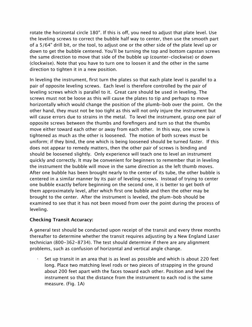
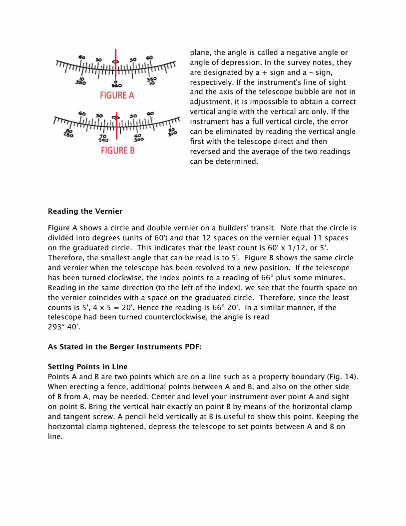
Reading the Vernier
Figure A shows a circle and double vernier on a builders' transit. Note that the circle is divided into degrees (units of 60') and that 12 spaces on the vernier equal 11 spaces on the graduated circle. This indicates that the least count is 60' x 1/12, or 5'. Therefore, the smallest angle that can be read is to 5'. Figure B shows the same circle and vernier when the telescope has been revolved to a new position. If the telescope has been turned clockwise, the index points to a reading of 66° plus some minutes. Reading in the same direction (to the left of the index), we see that the fourth space on the vernier coincides with a space on the graduated circle. Therefore, since the least counts is 5', 4 x 5 = 20'. Hence the reading is 66° 20'. In a similar manner, if the telescope had been turned counterclockwise, the angle is read 293° 40'.
As Stated in the Berger Instruments PDF:
Setting Points in LinePoints A and B are two points which are on a line such as a property boundary (Fig. 14). When erecting a fence, additional points between A and B, and also on the other side of B from A, may be needed. Center and level your instrument over point A and sight on point B. Bring the vertical hair exactly on point B by means of the horizontal clamp and tangent screw. A pencil held vertically at B is useful to show this point. Keeping the horizontal clamp tightened, depress the telescope to set points between A and B on line.

If the top of a stake cannot be seen, when you come to set point C, sight with the aid of a plumb bob, first, to find where to drive the stake, and second to note the point on the top of the stake. If it is necessary to continue this line beyond point C, center and level your instrument over point B, sight point C and continue this procedure.
9.2 PlumbingInstruments of the transit-level type can be used to advantage in plumbing such objects as building walls, columns, and flagpoles. Set and level your instrument at a point which is about as far away from the object as the object is tall. Select a point at the base of the object which is to be plumbed. Sight your telescope on this point and set the intersection of cross wires directly on it. By raising your telescope, you will find, through use of the line of sight and the cross-hairs, whether or not the object is plumb. If it is plumb, the object will appear not to move away from the cross-hair intersection. To completely check the plumb of the object, set the instrument at a position which is at an angle of 90° from the first position of the instrument and repeat the procedure. A corner post of a wood frame building is shown (Fig. 15) being plumbed.

Slopes and Rates of Grades
Several methods of defining slopes are shown above (Fig. 16).1. Horizontal distance to rise (or fall) in vertical; thus the grade is 4 to 1, or, more completely, 4 horizontal to 1 vertical.2. Rise or fall for each 100 feet horizontal. The slope, if extended for 100 feet horizontally would rise 25 feet. This is referred to as a 25% slope.3. Rise or fall for each one foot horizontal. Again, this would be designated as 0.25 foot per foot, or three inches per foot.4. Angle of slope is 14 degrees, 2 minutes (14° 2').
11.1. Grade Line for a SewerSteps to find the slope necessary for a household sewer connection are shown below (Fig. 17). Notice that the invert or flow-line of the pipe is used in each instance. The invert is the bottom of the pipe and this line is the reference from which grades are commonly given.
11.2. Batter Boards for a SewerSewers are normally placed at some depth below the surface of the ground, so batter boards are placed somewhat higher above the invert grade. A typical layout for sewer batter boards is shown below (Fig.18). The vertical strip nailed to the horizontal board is set with one edge along the line of the sewer. A nail is placed in this vertical strip at an even number of feet above the invert. By stretching a taut line between these nails, the sewer line is easily referenced. A board notched about 8 feet from its bottom is used to set the pipe.
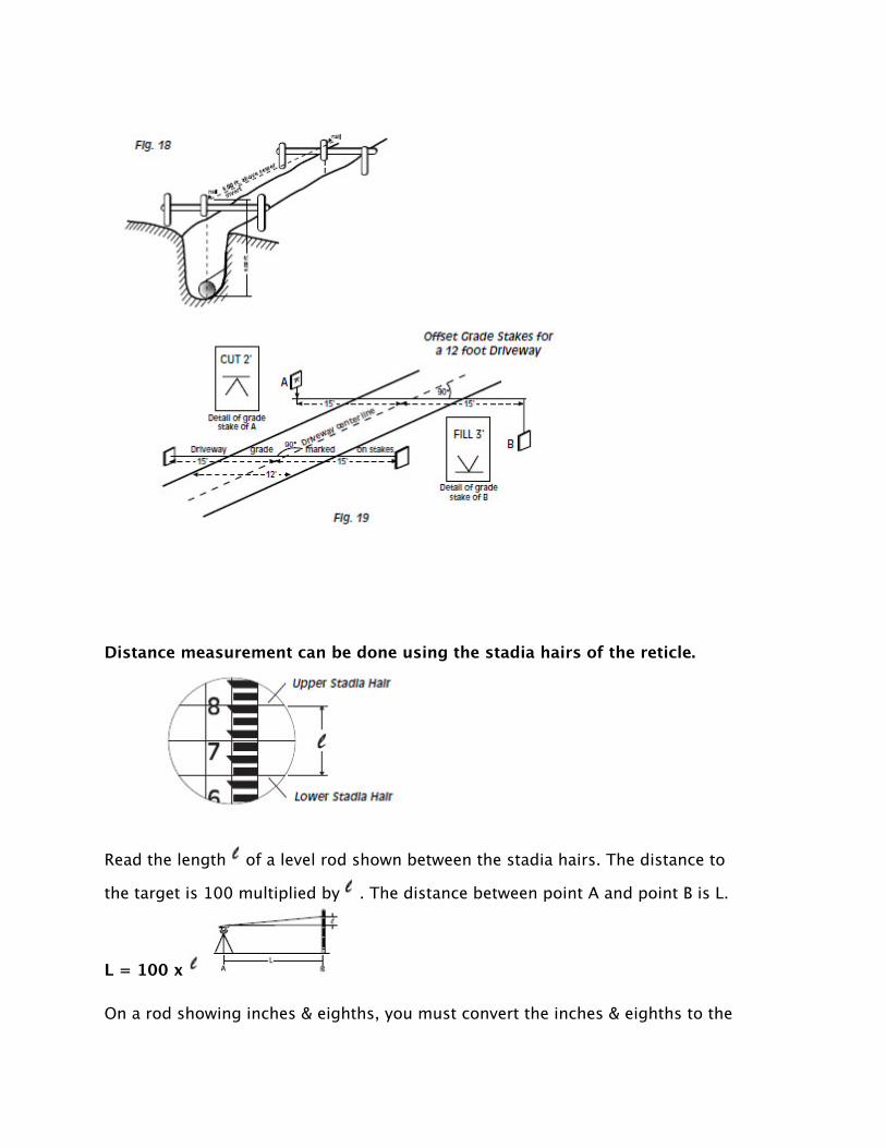
Distance measurement can be done using the stadia hairs of the reticle.
Read the length of a level rod shown between the stadia hairs. The distance to
the target is 100 multiplied by . The distance between point A and point B is L.
L = 100 x
On a rod showing inches & eighths, you must convert the inches & eighths to the

decimal form of a foot to get a correct reading. This is done by taking the partialfoot reading, say 7 1/8 inches, and converting by dividing by 12.
= 7.125"/12 = .59 FT.L = .59 x 100 = 59 FT.
If were 1' 7 1/8" then would equal 1.59 ft. & L = 159 ft.
New England Laser & Transit Company8 Reeds Mill Road, Newport, NH 03773
800-362-8734