How to Survive in Construction with Autodesk® Building Systems · Cad drafting in 2d over 2d cad...
22
Walt Disney World Swan and Dolphin Resort Orlando, Florida 11/29/2005 - 5:00 pm - 6:30 pm Room:N. Hemispheres (Salon E4) (Dolphin) How to Survive in Construction with Autodesk® Building Systems Keep your head above water, meet the deadlines, and provide well-coordinated 3D installation drawings from the mechanical contractor's point of view. Meet an end user as he shares his lessons learned in successfully implementing Autodesk Building Systems. Increase your productivity and learn shortcuts that work in the real world. You will learn how to effectively set up and share data across disciplines and subcontractors while still controlling the key parts of the design. Easily create custom parts and fill the gaps in your layouts to help you speed production in 3D drawing. Leverage and convert existing data while ensuring CAD standards are adhered to. ME22-2 About the Speaker: Bill Hashman - Total Mechanical, Inc. Bill is the CAD manager for Total Mechanical out of Portland, Oregon. Bill is licensed in HVAC piping and plumbing engineering/design and installation since 1981 and has used AutoCAD since 1988 to produce high-quality construction documents for HVAC systems. With the release of Autodesk Building Systems 2004, Bill has switched his focus to providing the same top-quality documents using this latest building engineering software. [email protected]
Transcript of How to Survive in Construction with Autodesk® Building Systems · Cad drafting in 2d over 2d cad...
Walt Disney World Swan and Dolphin ResortOrlando, Florida
11/29/2005 - 5:00 pm - 6:30 pm Room:N. Hemispheres (Salon E4) (Dolphin)
How to Survive in Construction with Autodesk® Building Systems
Keep your head above water, meet the deadlines, and provide well-coordinated 3D installation drawings from the mechanical contractor's point of view. Meet an end user as he shares his lessons learned in successfully implementing Autodesk Building Systems. Increase your productivity and learn shortcuts that work in the real world. You will learn how to effectively set up and share data across disciplines and subcontractors while still controlling the key parts of the design. Easily create custom parts and fill the gaps in your layouts to help you speed production in 3D drawing. Leverage and convert existing data while ensuring CAD standards are adhered to.
ME22-2
About the Speaker:
Bill Hashman - Total Mechanical, Inc.
Bill is the CAD manager for Total Mechanical out of Portland, Oregon. Bill is licensed in HVAC piping and plumbing engineering/design and installation since 1981 and has used AutoCAD since 1988 to produce high-quality construction documents for HVAC systems. With the release of Autodesk Building Systems 2004, Bill has switched his focus to providing the same top-quality documents using this latest building engineering [email protected]


How to Survive in Construction with Autodesk® Building Systems
2
Where we have been • In the medical profession there are advances in being able to see and diagnose to
greater levels of expertise with the help of technology.
Magnetic Resonance Imaging (MRI)
Before that - X-ray’s
And before that - Gray’s Anatomy
• We see a similar progression in construction drawings
Autodesk Building Systems over 2d, 2-1/2d, 3d cad backgrounds and Building Information Models (BIM)
Cad drafting in 2d over 2d cad backgrounds
Pen & Ink drafting over cad backgrounds
• A Lesson Learned - Looking back at 1987
One 1-1/4 pipe versus twelve 4” electrical conduits
And today – 18 years later – I was actually pleased when an electrician told me I wasn’t doing my job when I routed my pipe in his conduits.
I had to thank him for making a vision, started out of frustration 18 years ago, turn around and bite me back! Thanks to Dale & Mike at Cherry City Electric for putting me in my place (www.cherrycityelectric.com).
How to Survive in Construction with Autodesk® Building Systems
3
What we’re up against. • Lack of talent
“My experience has shown the main factor holding companies back from 3D adoption is the lack of personnel who can be immediately productive with 3D software. Companies are more than willing to reap the benefits of high-tech 3D design, but they don't want to pay the tab to do all the training, process changes and data management work required to take the leap into full-blown 3D design.”
Robert Green – Cadalyst Cad Managers newsletter Oct 26, 2005
We can overcome this by applying technologies that deal with the transition by providing a product that is the wise transition from 2d to 3d. We can do this by using 2-1/2d that is in Building Systems.
We don’t have hours to learn right now. So break down the tasks to fit the needs of the project. Building Systems is designed to provide the kind of interaction on your design team to accomplish this.
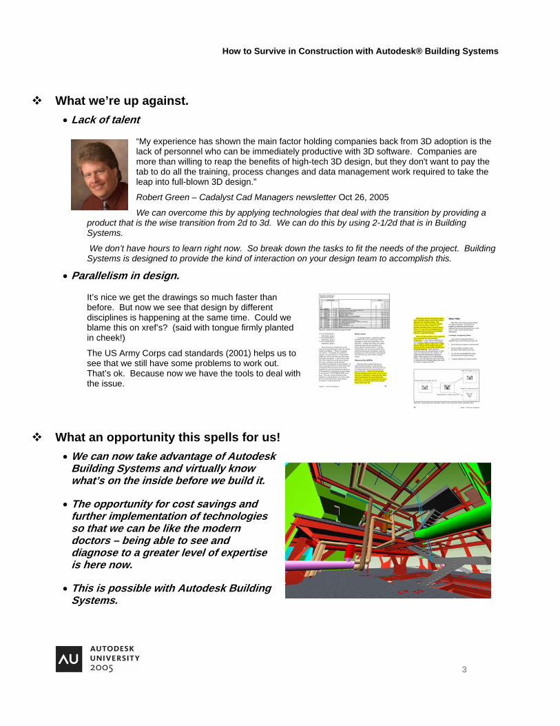
• Parallelism in design.
It’s nice we get the drawings so much faster than before. But now we see that design by different disciplines is happening at the same time. Could we blame this on xref’s? (said with tongue firmly planted in cheek!)
The US Army Corps cad standards (2001) helps us to see that we still have some problems to work out. That’s ok. Because now we have the tools to deal with the issue.
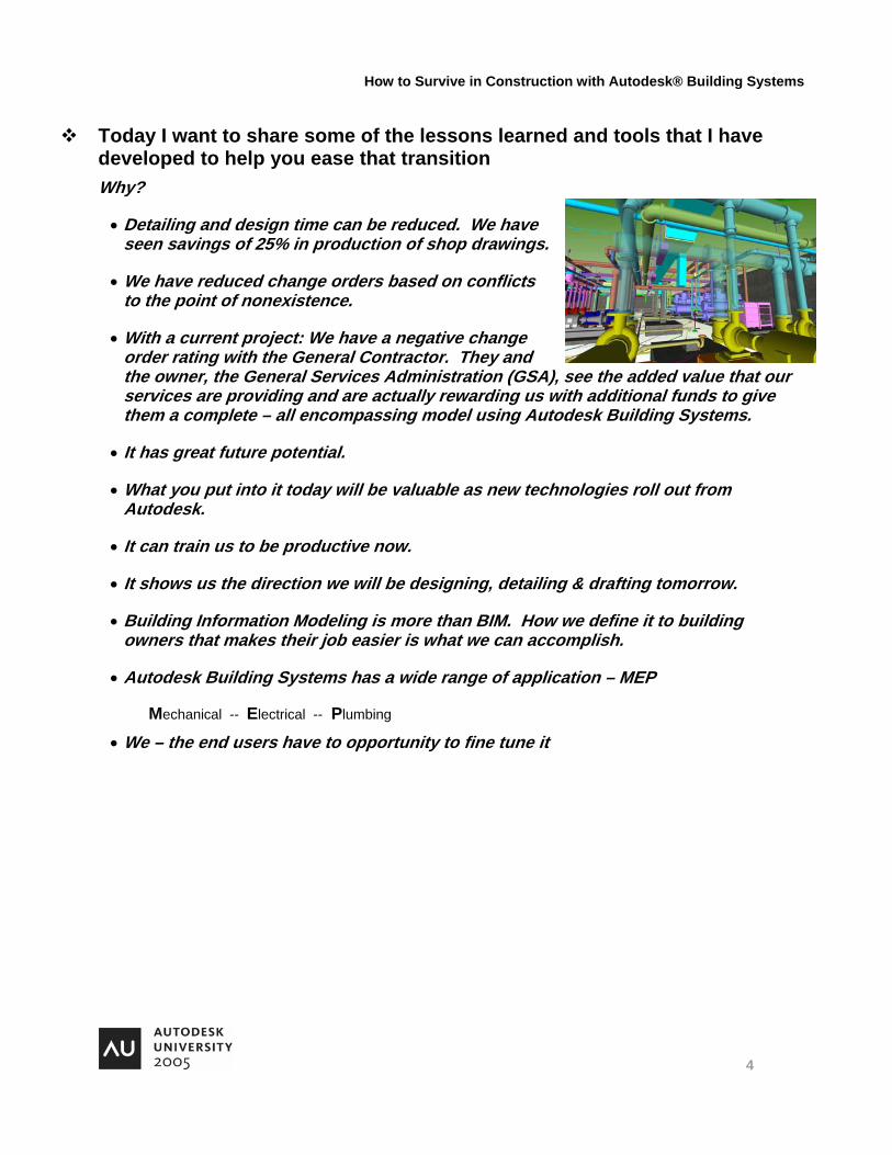
What an opportunity this spells for us! • We can now take advantage of Autodesk
Building Systems and virtually know what’s on the inside before we build it.
• The opportunity for cost savings and further implementation of technologies so that we can be like the modern doctors – being able to see and diagnose to a greater level of expertise is here now.
• This is possible with Autodesk Building Systems.
How to Survive in Construction with Autodesk® Building Systems
4
Today I want to share some of the lessons learned and tools that I have developed to help you ease that transition Why?
• Detailing and design time can be reduced. We have seen savings of 25% in production of shop drawings.
• We have reduced change orders based on conflicts to the point of nonexistence.
• With a current project: We have a negative change order rating with the General Contractor. They and the owner, the General Services Administration (GSA), see the added value that our services are providing and are actually rewarding us with additional funds to give them a complete – all encompassing model using Autodesk Building Systems.
• It has great future potential.
• What you put into it today will be valuable as new technologies roll out from Autodesk.
• It can train us to be productive now.
• It shows us the direction we will be designing, detailing & drafting tomorrow.
• Building Information Modeling is more than BIM. How we define it to building owners that makes their job easier is what we can accomplish.
• Autodesk Building Systems has a wide range of application – MEP
Mechanical -- Electrical -- Plumbing
• We – the end users have to opportunity to fine tune it

How to Survive in Construction with Autodesk® Building Systems
5
age. ng file
Set up Project Navigator successfully to share data across subcontractors and disciplines while still controlling the key parts. • File structure – why – where – how?
In many areas the mechanical contractor has the responsibility to provide the coordination lead.
This means we need to pull all the shop drawings together to provide coordinated “superplots.”
This job can be a lot easier if every one is on the same pThe primary source of headaches with xref’s is conflictistructures.
Yet it is possible to set up the structure and share it across several subcontractors.
What we did is set up the structure, then spent the time to go to each stakeholder in the process and help them improve their claim with Autodesk Building Systems and a common file structure.
We went in and studied their file/server organization and came up with a schema that was friendly to all stakeholders.
You can map a drive to match your J drive.
Or use a DOS batch file to build the path and keep it solid.
The DOS subst command:
• Path the project from the root directory.
Then all data is secure from our file structure. We use eTransmit to finalize the data and switch to reference path in the xref’s for the owner “as recorded” drawings.
Relative path structure is something we are experimenting with. But it can be dangerous to those not familiar with file organization structures. Let them design and not worry about the path by making them all look the same as any other document they file on a computer.

How to Survive in Construction with Autodesk® Building Systems
6
Get them on board. Show them the benefits.
y
ced
ing shown here is
• Using elements for parts and equipment.
What is an element? Help will tell you: “Elements represent pieces that are used multiple times within a building.”
Elements can also be other parts that can simplify your drawings into smaller group of objects to reduce complexity. Repeating lavatory risers. Access doors and zones. Or a repository of commonly used parts.
Elements can help you to split the work to fit the business model and ease the learning curve while handling growth.
Now we can take a complex drawing and break it into parts that are smaller and less intimidating to teach to others.
What kinds of things can be used as an element?
Air Valve boxes.
Condensate pumps and related piping.
Small plumbing riser piping to a single fixture or a part of the plumbing system that repeats.
• Set up a team to gain real-time efficiencies.
You will learn that they never thought that theycould. But now they can’t work without it.
Mike Barrett with Cherry City Electric neverthought that what they could be doing today would solidify their efforts to gain production efficiencies with the field crews. Also the benefits of a complete 3d riser location that allows you to fly through and check continuitand service has brought forward issues that would usually have not been discovered till much later in the building process. This redua potential change order cost.
The complete data conduit routan example of a successful use of Building Systems for a cost savings and an opportunity for added value in a current project.

How to Survive in Construction with Autodesk® Building Systems
7
• UsPr
split the tasks between your team. The best person for
ct xref paths.
We also organize and keep track of 8-1/2 x 11 sketches with the sheet tab and publish these quickly with WDF. Use the “import current layout as sheet” function. Number them per the PBS standards using the “user defined” field.
Create custom parametric parts to fill the gaps and build• Round to square w
rig
Does the out of the box one work? Sorry… But that’s OK.
The Eccentric Flag does not work yet! We can deal with that too.
If you switch your view around to the front of the model and work
xis.
e circle first when aking the Modifier Transition path? Or the rectangle? ou can get funny results. Try to pick the item with the
with a
e smart DWF technologies to Publish sheets from oject Navigator
You canviews and sheets is your network/techie. The one who understands files and directories the best is the one to teach views and sheets because they live and die with similar problems. Like corre
content hile flat on top, or bottom, or left, or
ht, or …….
towards you, then you are staying positive in the x aSE Isometric works well.
Build from 0,0 out to the right. Keeping most of your entities in a positive plane.
Build your connection data planes from xy positive working out from 0,0,0 as your control plane.
Which should you pick first? Pick thmYhigher z value first, working back into the object lower z value.
Be careful not to build fixed points.
How to Survive in Construction with Autodesk® Building Systems
8
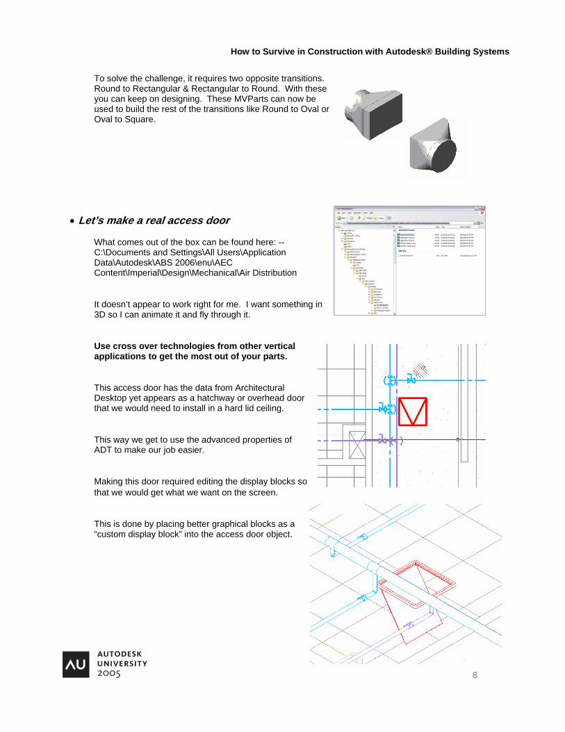
o solve the challenge, it requires two opposite transitions. ound to Rectangular & Rectangular to Round. With these ou can keep on designing. These MVParts can now be
used to build the rest of the transitions like Round to Oval or Oval to Square.
• Le
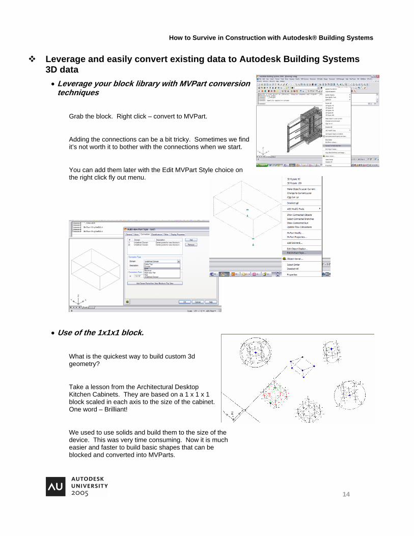
Content\Imperial\Design\Mechanical\Air Distribution
thing in 3D so I can animate it and fly through it.
way or overhead door that we would need to install in a hard lid ceiling.
of ADT to make our job easier.
so that we would get what we want on the screen.
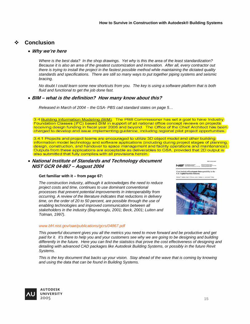
This is done by placing better graphical blocks as a “custom display block” into the access door object.
TRy
t’s make a real access door
What comes out of the box can be found here: -- C:\Documents and Settings\All Users\Application Data\Autodesk\ABS 2006\enu\AEC
It doesn’t appear to work right for me. I want some
Use cross over technologies from other vertical applications to get the most out of your parts.
This access door has the data from Architectural Desktop yet appears as a hatch
This way we get to use the advanced properties
Making this door required editing the display blocks

How to Survive in Construction with Autodesk® Building Systems
9
Learn shortcuts to speed production in 3D drawings • Section It
The fastest way to work productively is flat – orthographically. But how can we do that from a side view? There are several options.
The command to make a section is: AECVERTICALSECTION
After you move it around there is a little delay as it does something like caching the visible graphics inside the bounding box. Is there another way? Yes.
There is another way to cut the cake – lift out a piece – and look at it from the side. Section It.
This routine is based on the old favorite yet rarely used DVIEW command.
You can also use Section It and 3dOrbit to make some dramatic presentation views with the clipping planes and camera position quickly established.
• pipe slope routines
If you can’t get the pipe to slope correctly it can be frustrating. If Building Systems puts the pipe in flat, there is a way to build the slope into the system that is fast.
This series of commands looks at the nodes at each end of the pipe and moves the fittings up the appropriate amount based on the slope percentage. The menu buttons trigger the most common pipe slopes. But this simple lisp routine can be called directly with other slopes if needed.
Further development in slope and grading of piping systems is happening in Building Systems. But this tool can get you to your deadline quickly until that day arrives.
• Cross linking technologies to get what you need
The ADT access door – there are other items out there too.
Use HVAC ducts for electrical bus ducts. It’s fast and can be adjusted to accommodate any size and sweep.
We need to reserve the space for the pipe rack and not worry about the contents at this time. Use HVAC duct routines to show the intent. Fill in the details later or develop tags that show the contents and provide the rack details to close the gaps.

How to Survive in Construction with Autodesk® Building Systems
10
Get familiar with rarely used commands that make you fast • “REGEN ALL” versus
"REGENERATE MODEL" – Is there is a difference?
OBJRELUPDATE command.
It’s important for fields and connectivity.
• Pipes not displaying correctly?
REVERSESEGMENT command
Place it on the fly out menu with the Custom User Interface (CUI)
• How do you make a live section on the fly?
AECVERTICALSECTION command.
This one fits well in a fly out menu too. As long as the drawings are not too big – it performs well.

How to Survive in Construction with Autodesk® Building Systems
11
Learn how to implement the GSA - PBS CAD Standards into Project Navigator • How do you apply the General Services Administration-Public
Building Services file naming convention to Building Systems Project Navigator?
To Z or not to Z – that is the Z question…
It appears there is little governance at the shop drawing level. US Army Corps standard appears to give us the same instructions. Here is an excerpt from emails I have sent hoping to get some help. What happens with multiple discipline shop drawings? Example: This example is of the design drawings for the Eugene Federal Courthouse - Level 5 - the plan views which are designated with the letter "A" at the end of the secondary designator for the north half of the building: The architectural design drawing is known as: a_0105a.dwg The electrical design drawings are known as: EP_105A.dwg (for power) EL_105A.dwg (for lighting) The mechanical design drawings are known as: m_0105ac.dwg (for ceiling) m_0105af.dwg (for under floor) The plumbing design drawings are known as: p_0105a.dwg (for ceiling) p_0105a.dwg (for under floor) If I understand what PBS is telling me then the shop drawing for architectural, mechanical, electrical and plumbing would end up like this. z_0105a.dwg - for the architectural shop drawing z_105A.dwg - for the electrical power shop drawing z_105A.dwg - for the electrical lighting shop drawing z_0105ac.dwg - for the HVAC duct shop drawing z_0105af.dwg - for the HVAC duct under floor shop drawing z_0105a.dwg - for the plumbing shop drawing This does not make sense as drawing names for different disciplines are going to end up having the same name and they also lose what discipline they were associated with. Hypothesis: Place the Z for shop drawings in front of the drawing name primary discipline designator. Thus: zA_0105a.dwg - for the architectural shop drawing zEP_105A.dwg - for the electrical power shop drawing zEL_105A.dwg - for the electrical lighting shop drawing

How to Survive in Construction with Autodesk® Building Systems
12
hem
Now the HVAC and plumbing drawings are typically used by engineers in our locale to show two separate disciplines. These two separate disciplines end up making their own shop drawings and many times they are installed by two separate contractors. With the HVAC design drawings they get split to make the HVAC duct shop drawings and the HVAC piping drawings. With the Plumbing drawings they get split to make the Plumbing shop drawings and the Fire Sprinkler shop drawings. Obviously the PBS and U.S. Army Corps Cad Standards would make the shop drawings useless to the owner if the "Replace it with a Z" instruction was followed. Instead I propose the following based on the elements within the PBS standard that give us some guideline for a more specific primary and secondary designator. zMH_0105ac.dwg - for the HVAC duct shop drawing zMH_0105af.dwg - for the HVAC duct under floor shop drawing zMP_0105ac.dwg - for the HVAC piping shop drawing zMP_0105af.dwg - for the HVAC piping under floor shop drawing zP_0105a.dwg - for the plumbing shop drawing zPF_0105a.dwg - for the fire sprinkler shop drawing The problem with this solution is that it does not follow the 2-4-4 AIA naming convention that is prevalent in both GSA standards. Instead, because of shop drawings we may need to go to a 3-4-4 structure to truly designate the primary drawing discipline within the first few characters of the drawing name. The Z would be appended to the front of the primary two character designator. Possibly the Z would need to be separated with a hyphen for clarity.
• Layer naming convention
The same structure for shop drawing information that is critical to the owner in making sure data is not confused with other stakeholders’ data and layers is necessary. Placing the Z on the front does the trick to keep us unique.
• Where do you put the views?
GSA cad standards do not give a view file naming convention. Possibly it exists elsewhere but this is what we have found to be acceptable…
The PBS standard gives good information about two of the three levels in file organization with Building Systems.
But views need a home too. And placing tinto this structure is quite easy.
We also see from the cad standard what the name of our view file could be: ZP-PP01-VIEW

How to Survive in Construction with Autodesk® Building Systems
13
• What should our ctb files look like?
There are acceptable ctb files that are still in use since the BIM by 2006 initiative, listed in the 2004 PBS cad standards, has been delayed. What do the acceptable ctb files look like?
We have taken the time to analyze the structure and place them in charts that can quickly be referenced.
There are enough options in these tables that custom ctb files, away from the standard definition, are really a thing of the past. Holding on to them will only hinder your forward progress. Accept the simplest solution that leads to the highest productivity and greater conformance with others.
Right out of the box we get this from Building Systems with the American Institute of Architects layer standards ctb files. These are GSA-PBS compliant.
By the way – all the Building System objects conform to the American Institute of Architects layer standards for good quality prints in a hurry.
How to Survive in Construction with Autodesk® Building Systems
14
abinet.
Leverage and easily convert existing data to Autodesk Building Systems 3D data • Leverage your block library with MVPart conversion
techniques
Grab the block. Right click – convert to MVPart.
Adding the connections can be a bit tricky. Sometimes we find it’s not worth it to bother with the connections when we start.
You can add them later with the Edit MVPart Style choice on the right click fly out menu.
• Use of the 1x1x1 block.
What is the quickest way to build custom 3d geometry?
Take a lesson from the Architectural Desktop Kitchen Cabinets. They are based on a 1 x 1 x 1 block scaled in each axis to the size of the cOne word – Brilliant!
We used to use solids and build them to the size of the device. This was very time consuming. Now it is much easier and faster to build basic shapes that can be blocked and converted into MVParts.
How to Survive in Construction with Autodesk® Building Systems
15
Conclusion • Why we’re here
Where is the best data? In the shop drawings. Yet why is this the area of the least standardization? Because it is also an area of the greatest customization and innovation. After all, every contractor out there is trying to install the project in the fastest possible method while maintaining the dictated quality standards and specifications. There are still so many ways to put together piping systems and seismic bracing.
No doubt I could learn some new shortcuts from you. The key is using a software platform that is both fluid and functional to get the job done fast.
• BIM – what is the definition? How many know about this?
Released in March of 2004 – the GSA- PBS cad standard states on page 5…
• National Institute of Standards and Technology document NIST GCR 04-867 – August 2004
Get familiar with it – from page 67:
The construction industry, although it acknowledges the need to reduce project costs and time, continues to use dominant conventional processes that prevent potential improvements in interoperability from occurring. A review of the literature indicates that reductions in delivery time, on the order of 20 to 50 percent, are possible through the use of enabling technologies and improved communication between all stakeholders in the industry (Bayramoglu, 2001; Beck, 2001; Luiten and Tolman, 1997).
www.bfrl.nist.gov/oae/publications/gcrs/04867.pdf
This powerful document gives you all the metrics you need to move forward and be productive and get paid for it. It’s there to help you and your customers see why we are going to be designing and building differently in the future. Here you can find the statistics that prove the cost effectiveness of designing and detailing with advanced CAD packages like Autodesk Building Systems, or possibly in the future Revit Systems.
This is the key document that backs up your vision. Stay ahead of the wave that is coming by knowing and using the data that can be found in Building Systems.

How to Survive in Construction with Autodesk® Building Systems
16
he
t
t
• “IFC” Industry Foundation Classes
“For the IFC model to facilitate full interoperability between applications, it would have to be a superset of all their data models, which would be a near-impossible task. It is important to keep this in mind so that expectations from the IFC do not exceed what is realistically possible.”
“At the same time, it is important not to burden the IFC with over-expectations of being the be-all and end-all of interoperability in tbuilding industry.”
“…seamless integration of a suite of commercial applications based on the IFC format has not yet been demonstrated, except for carefully modeled test projects, indicating that the effort hasn't yet reached the point where it is ready for mass consumption. However, it is definitely something to watch out for because once it works fully as envisioned, its integration capabilities and collaborative benefits can go a long way towards eliminating the inefficiencies and waste in the building industry. “
Lachmi Khemlani, The IFC Building Model: A Look Under the Hood. AECbytes March 30, 2004
“… IFC only represents the basic building information that can be modeled by a BIM application during the design stage.”
Lachmi Khemlani, CORENET e-PlanCheck: Singapore's Automated Code Checking System. AECbytes "Building the Future" Article October 26, 2005
IFC is not mature enough to be a concern to us yet. We will need more Industry Foundation Classes before it can give us interoperability. Someday, hopefully soon, we will see this. In the mean time – the best way to give your clien Building Information Modeling (BIM) at the Mechanical, Electrical, and Plumbing (MEP) level is Autodesk Building Sys ems.
• Where we are headed
Coordinated drawings - Avoid color overlays and arcane methods – use technology to save time and valuable resources. Building Systems and Navisworks are real world, lean method, efficiency tools for reduced production costs.
Know what’s on the inside before you build it. It is possible today with rapid visualization of issues using Building Systems.
How to Survive in Construction with Autodesk® Building Systems
17
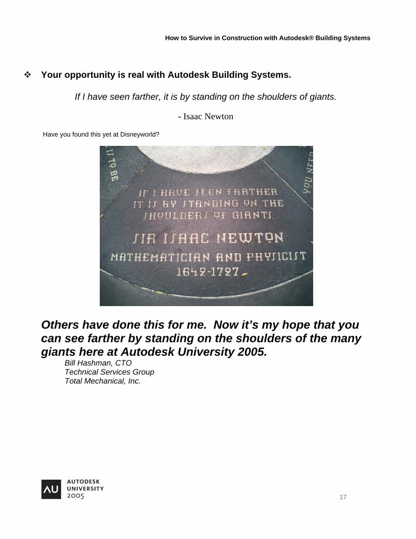
Your opportunity is real with Autodesk Building Systems.
If I have seen farther, it is by standing on the shoulders of giants.
- Isaac Newton
Have you found this yet at Disneyworld?
Others have done this for me. Now it’s my hope that you can see farther by standing on the shoulders of the many giants here at Autodesk University 2005.
Bill Hashman, CTO Technical Services Group Total Mechanical, Inc.

How to Survive in Construction with Autodesk® Building Systems
18

How to Survive in Construction with Autodesk® Building Systems
19
How to Survive in Construction with Autodesk® Building Systems
20
talmechanical.com
Recommended reading and websites Building Connections: The 1st Congress on Digital Collaboration in the Building Industry- Jonathan Cohen & Associates – www.jcarchitects.com/building_connections.html
Virtual Design-Build Organizations: Enabling Process Change in the Building Industry - Jonathan Cohen & Associates - www.jcarchitects.com/virtual_orgs.html
National Institute of Standards and Technology – Grant Contractor Reports - http://www.bfrl.nist.gov/oae/publications/gcrs.html
Is there a person missing from your building project team – the Interoperability Consultant? By Ian Howell and Todd Kozikowski – http://www.ifma.org/daily_articles/2005/may/05_01.cfm
Engineering News – Record – the McGraw Hill Companies – www.enr.com
AECbytes Newsletter - Lachmi Khemlani – www.aecbytes.com
Plant Engineering – Reed Busines Information - www.manufacturing.net/ple/
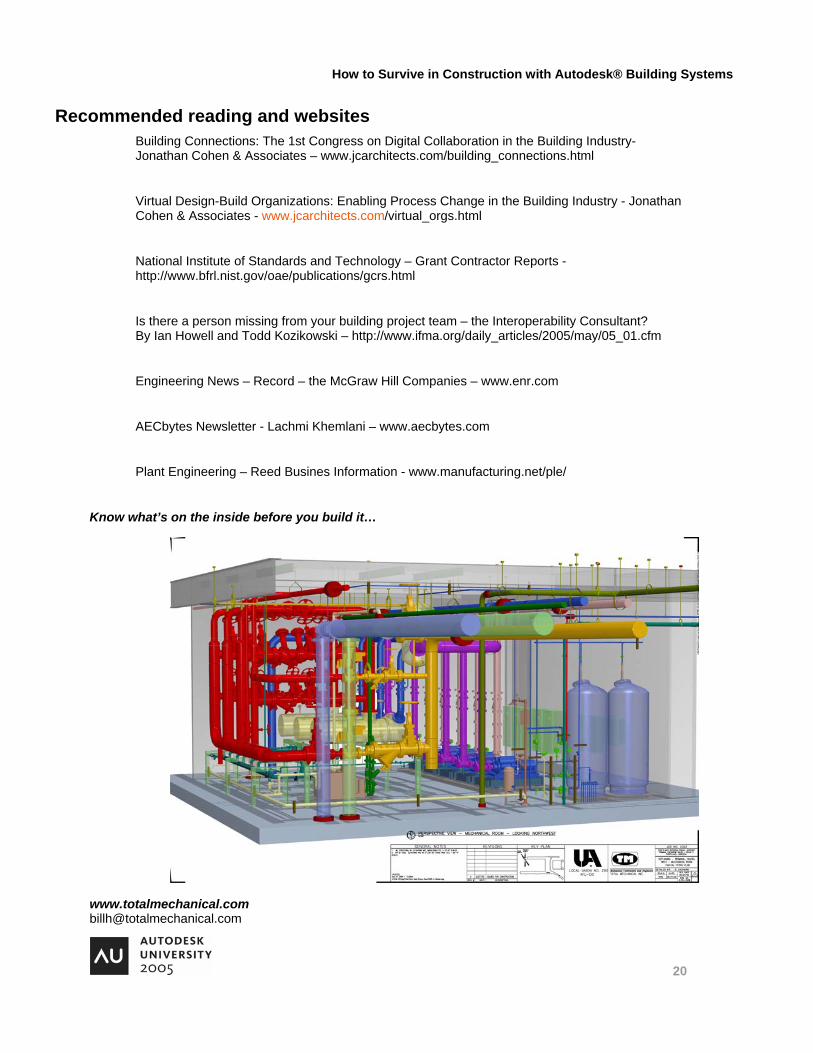
Know what’s on the inside before you build it…