
How to Solder Electronics - University of Virginia
78
15 Rules for Successful Soldering How to Solder Electronics
Transcript of How to Solder Electronics - University of Virginia

i
www.sra-solder.com
15 Rules for Successful Soldering
How to Solder Electronics

www.sra-solder.com
How to Solder Electronics15 Rules for Successful Soldering
Written and published by
SRA Soldering Products

iii
www.sra-solder.comwww.sra-solder.com
How to Solder Electronics: 15 Rules for Successful Soldering Written and Published by SRA Soldering Products 24 Walpole Park South, Suite #10, Walpole, MA 02081 www.sra-solder.com
© 2020 SRA Soldering Products
All rights reserved. No portion of this book may be reproduced in any form without permission from the publisher, except as permitted by U.S. copyright law. For permissions contact:
ISBN: 9798656683746

iv
www.sra-solder.com
Contents
Introduction .......................................................................................viii
Rule #1 – Know the Fundamentals ��������������������������������������������1What is Flux? ......................................................................................1
What is Solder? ...................................................................................1
What is Wetting? .................................................................................2
Methods of Heat Transfer ....................................................................3
The Difference Between Soldering, Brazing, and Welding .................4
When Do I Need to Solder? ................................................................6
Rule #2 – Identify the Construction Method �����������������������������8Breadboards and Learning Labs .........................................................8
Computer Simulations .........................................................................9
Protoboard, Perfboard, and Stripboard ...............................................9
Point-to-Point ....................................................................................10
Tag Board, Turret Board, Eyelet Board .............................................10
Through-Hole Technology (THT) ....................................................... 11
Surface-Mount Technology (SMT)..................................................... 11
Rule #3 – Choose the Right Solder and Flux ��������������������������12Forms of Solder .................................................................................12
Leaded Solder Alloys ........................................................................13
Lead-Free Solder Alloys ....................................................................14

v
www.sra-solder.com
Solder Wire Gauge ............................................................................15
Solder Spool Size ..............................................................................15
Choosing a Flux ................................................................................16
Rule #4 - Use the Right Tools ���������������������������������������������������20Soldering Iron ....................................................................................20
Soldering Stations .............................................................................21
Soldering Iron Stand .........................................................................22
Soldering Iron Tip Types....................................................................23
Soldering Iron Tip Shapes .................................................................24
Special Tips .......................................................................................25
Tools for Cleaning .............................................................................26
Tools for Desoldering ........................................................................27
Tools for Tinning ................................................................................27
Tools for Wire Stripping .....................................................................28
Other Helpful Tools ............................................................................29
Rule #5 – Practice Soldering Safety ����������������������������������������32Fume Extractors (Smoke Absorbers) ................................................32
Soldering Mats ..................................................................................32
What is ESD? ....................................................................................33
Leaded Solder Exposure ...................................................................34
Gloves ...............................................................................................34
Protective Eyeglasses .......................................................................34

vi
www.sra-solder.com
Rule #6 – Understand the Art of Heat Transfer �����������������������35Managing the Heat Cycle ..................................................................35
Rule #7 - Use the Right Temperature ���������������������������������������36Heat Sinks .........................................................................................36
Rule #8 - Keep Your Surfaces Clean ����������������������������������������37Keeping Your Iron Tips Clean ............................................................37
How to Clean Using a Wet Sponge ...................................................38
How to Clean Using Brass Coils .......................................................39
Maximzing Tip Life ............................................................................40
Rule #9 – Keep Your Tip Tinned �����������������������������������������������41How to Tin Your Tip ...........................................................................41
Rule #10 - Pay Attention to Surface Mass �������������������������������43Use the Contact Patch Advantage ...................................................43
Make Sure Your Iron is Powerful Enough .........................................44
Rule #11 - Place Your Components Securely �������������������������45Axial Versus Radial Leads ................................................................45
The Art of Lead Forming ...................................................................46
How to Form Component Legs .........................................................46
How to Prepare IC Chips ..................................................................48
Rule #12 – Add Solder and Heat Simultaneously �������������������49How to Solder Through-Hole Components .......................................49

vii
www.sra-solder.com
How to Solder Wires .........................................................................51
Rat-Tail or Twist Splice .....................................................................54
How to Make a J-Hook Connection ...................................................55
Lineman’s Knot or Western Union Splice .........................................57
Rule #13 – Inspect and Evaluate the Joint ������������������������������59The Ideal Solder Joint .......................................................................59
Common Soldering Errors .................................................................59
Not Enough Heat ...............................................................................60
Too Much Heat ..................................................................................61
Too Much Solder ...............................................................................62
Not Enough Solder ............................................................................63
Moved Component ............................................................................64
Rule #14 - Desolder If Necessary ���������������������������������������������65The Manual Desoldering Pump .........................................................65
How to Use a Desoldering Pump ......................................................66
More Desoldering Pump Tips ............................................................67
Rule #15 - Clean Up Your Mess ������������������������������������������������69Trim Your Leads ................................................................................69
Clean Flux Residues .........................................................................69
Final Thoughts ...................................................................................70

viii
www.sra-solder.com
Introduction
Here at SRA, we believe anyone can solder! After all, it’s not hard to learn how
to melt some solder and make an electrical connection. In our 60 years of providing
soldering and brazing solutions, we’ve found that most solder problems are due to a
lack of knowledge, experience, or the proper tools for the job. Our aim with this guide
is to explain the science behind how soldering works, why various reactions occur, and
how to produce a highly reliable connection with these factors in mind. Whether you
are a beginner, experienced technician, or manufacturer this information should prove
useful to your studies and skillset. If you’re someone who struggles with soldering, this
will help you understand the “why” so you can improve. In order to make this guide easy
to follow, we have broken it down into 15 rules that cover everything you need to know
including our best techniques for soldering success!

Rule #1 - Know the Fundamentals1
www.sra-solder.com
Rule #1 – Know the Fundamentals
First things first, let’s define what we’re talking about here. Some people say ‘sol-der’, others say ‘sodder’. It all depends on where you’re from but believe it or not, they mean the same thing! The term solder can be expressed as both a verb and a noun. The verb ‘to solder’ describes the action of joining together two or more pieces of metal using soldering techniques. While solder the noun, refers to the so-called “glue” used to keep the metals together.
What is Solder?
Solder can technically be described as a filler metal that is melted and flowed into a solder joint (the location where electronic components and workpiece meet) to form a mechanical and electrically conductive connection.
The primary metal used to make solder is Tin (Sn) but it usually includes other metals and additives that alter its physical properties. These special solder alloys (mixtures of metal) make it possible to go from a solid to a liquid and back very quickly, using a simple heat source such as a soldering iron. The most important thing to know about solder though is that it will not work without flux.
What is Flux?
Flux is a chemical agent that de-oxidizes the metals you’re soldering. This provides a clean surface for the solder to adhere to. Flux is commonly found inside solder wire but also in liquid and paste forms. Earlier we described solder as “glue” but without flux or enough flux, the solder will not be able to bond properly in a process called wetting.
Rule #1 - Know the Fundamentals2
www.sra-solder.com
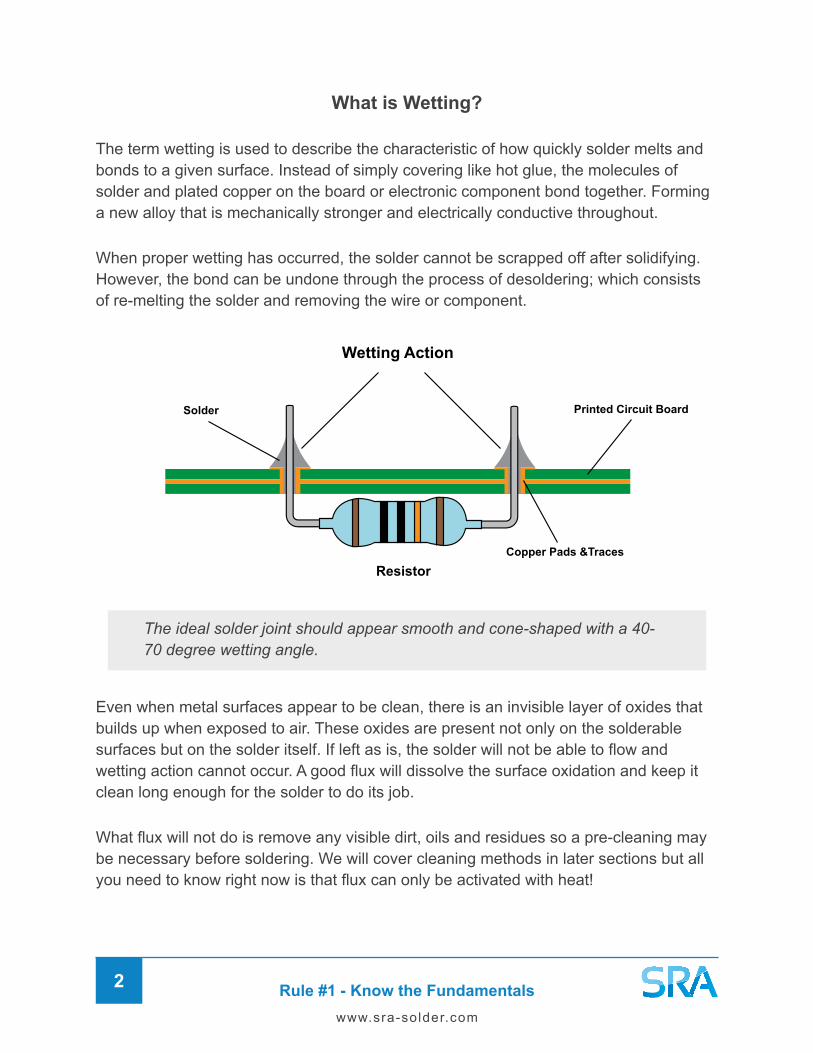
What is Wetting?
The term wetting is used to describe the characteristic of how quickly solder melts and bonds to a given surface. Instead of simply covering like hot glue, the molecules of solder and plated copper on the board or electronic component bond together. Forming a new alloy that is mechanically stronger and electrically conductive throughout.
When proper wetting has occurred, the solder cannot be scrapped off after solidifying. However, the bond can be undone through the process of desoldering; which consists of re-melting the solder and removing the wire or component.
Wetting Action
Printed Circuit Board
Copper Pads &Traces
Resistor
Solder
The ideal solder joint should appear smooth and cone-shaped with a 40-70 degree wetting angle.
Even when metal surfaces appear to be clean, there is an invisible layer of oxides that builds up when exposed to air. These oxides are present not only on the solderable surfaces but on the solder itself. If left as is, the solder will not be able to flow and wetting action cannot occur. A good flux will dissolve the surface oxidation and keep it clean long enough for the solder to do its job.
What flux will not do is remove any visible dirt, oils and residues so a pre-cleaning may be necessary before soldering. We will cover cleaning methods in later sections but all you need to know right now is that flux can only be activated with heat!

Rule #1 - Know the Fundamentals3
www.sra-solder.com
Methods of Heat Transfer
Solder, flux, and heat make up the three essentials of soldering. Without just one of them, the process is not possible. There are also three distinct methods of heat transfer when it comes to soldering, each of them using different tools to accomplish the task.
Conduction - Hand Soldering
This method typically uses a soldering iron as the heat source and will be the primary focus of this guide. A great deal of electronics soldering can be done through conduction hand soldering.
Convection - Reflow Soldering
This method typically uses a hot air gun, specialized oven, or furnace as the primary heat source. Reflow is necessary for electronic components that are too small to solder with an iron. This method is sometimes referred to as “sweat soldering”, especially in the plumbing and jewelry industries.
Combination - Wave Soldering
This final method uses a wave soldering oven that combines conduction and convection as the heat source. It is an automated process used in manufacturing to solder devices quickly and efficiently with a wave of molten solder.

Rule #1 - Know the Fundamentals4
www.sra-solder.com
The Difference Between Soldering, Brazing, and Welding
Soldering is not to be confused with the terms brazing or welding, which also describe the process of joining two or more metals. People will often use these words interchangeably, very commonly referring to brazing as soldering. However, these processes differ in three distinct ways.
Temperature Range
The main difference is the temperature range in which they occur. Solder alloys with melting temperatures below 840°F (450°C) are considered to be “soft” while any soldering above that point is referred to as “hard soldering” or brazing; also called silver soldering when an alloy containing silver is used. Brazing is used in industrial applications such as plumbing, jewelry, and dentistry. Whereas all electronics work is considered soft soldering.
As for welding, the process occurs much higher up on the scale at around 10,000°F (5500°C) and up! The chart below shows where these processes occur along with the melting points for popular solder alloys used.

Rule #1 - Know the Fundamentals5
www.sra-solder.com
Equipment Used
The second difference is the equipment required to reach each respective temperature range. Since soft soldering occurs at a relatively low temperature, it can be done with just a soldering iron, hot air gun, or preheater. Whereas the higher temperatures used for brazing require a butane torch, acetylene torch, hydrogen torch, or furnace. Finally, the extremely high temperatures used for welding require a MIG, TIG or ARC welder capable of producing a lot of current.
Joining Process
The final difference is the process by which the metals are joined. For soft and hard soldering the process is the same. The solder alloy used has a lower melting point than the metal it is being applied to. In these reactions, the solder alloy is melted and bonds to the work pieces through solution or wetting action.
Welding is fundamentally different than soldering or brazing because the work pieces themselves are being melted and fused together; meaning it is not reversible. A filler metal is still used in the process but the joint formed is actually stronger than the original base materials. Welding is common in metal fabrication, construction, and other industrial manufacturing applications where the utmost strength is needed.
BrazingSoldering Welding

Rule #1 - Know the Fundamentals6
www.sra-solder.com
When Do I Need to Solder?
At this point, you should be fairly confident in your knowledge of metal joining processes using solder and heat. But what about the increasing number of solderless solutions that are out there? We assume you’re reading to learn how to solder but we believe there are distinct advantages and disadvantages to both, as well as certain times to use them. We also think an explanation will help you understand the benefits of soldering, so let’s get into it!
Solderless Advantages
þ Minimal Investment in equipment and parts
þ Ease of use, very simple to make a connection
þ Convenient to disconnect if you need to change or repair something
Solderless Disadvantages
ý Purely a mechanical connection, reliant on tension only
ý Exposure to air and condensation will cause oxidation over time
ý Movement and vibration will loosen the connection over time. Every time a solderless cable is plugged or unplugged, the integrity weakens
ý Nuts & bolts or set screws can only be tightened so much before breaking the connecting wires

Rule #1 - Know the Fundamentals7
www.sra-solder.com
Soldered Advantages
þ Proper soldering creates a permanent connection that is air-tight. Since the solder joint becomes encapsulated in solder, the risk of oxidation is diminished.
þ Soldering creates a very strong mechanical connection and a electrically conductive path between the parts.
þ The resulting connection is highly reliable under most conditions including vibration. Soldered connections can take a lot more abuse than solderless.
Soldered Disadvantages
ý Greater investment in equipment needed to produce a proper solder joint.
ý Takes some time to learn the skill and solder proficiently.
In our opinion, solderless solutions are best used in instances where high reliability is not a requirement. Components that will exist only in low stress conditions or are expected to be changed in the near future are the best candidates. Also, in areas where a soldering iron is not as feasible such as electrical receptacles or in vehicles.
We do recommend solderless connections for prototyping and testing but when it comes time to construct a finished product, soldering is necessary. Likewise, anything that needs to withstand a lot of abuse and last a long time should be soldered. Especially wires and cables that will be plugged and unplugged frequently.

Rule #2 - Identify the Construction Method8
www.sra-solder.com
Rule #2 – Identify the Construction Method
There are many ways to build a circuit using both soldered and solderless methods. All circuits are comprised of a collection of electronic components that come together to form an electrical device. Getting to know each type of component and their purpose is important to designing and building a circuit. This guide won’t address circuit design, but it will consider the different types of construction you may come across.
Breadboards and Learning Labs
When first conceptualizing a circuit, you may want to produce a prototype for testing. This can be done quickly on a breadboard, which is a solderless prototyping device with little holes for component leads that are electrically connected by internal busses.
There are also electronic learning boards available that include a breadboard with other components such as potentiometers, connectors, and even a speaker built-in for completing a variety of projects. Some technicians prefer to build their own prototyping devices with their favorite and most used parts to aid in creating new circuits.

Rule #2 - Identify the Construction Method9
www.sra-solder.com
Computer Simulations
Alternatively, you could use computer simulation software like Multisim LIVE or TinkerCAD to design and layout your circuit. Multisim is better suited for creating schematics while TinkerCAD is more visual layout based. It’s also great if you don’t have parts on hand or want an idea of the outcome before building. TinkerCAD even has drag-and-drop components for Arduino builds!
Protoboard, Perfboard, and Stripboard
There comes a time where you’ll want to test your circuits under real-life conditions by creating a soldered prototype. Protoboard or perfboard is perfect for this because it has lots of holes with pads on which to solder. Stripboard is similar, except the holes are connected to each other by copper strips. The holes are very closely populated on both, allowing you to create solder paths by bridging them with solder for flexible layout options. Ease of use makes these great options for protyping and practicing your soldering skills!

Rule #2 - Identify the Construction Method10
www.sra-solder.com
Point-to-Point
Once upon a time before circuit boards, electronics devices were constructed with component leads soldered directly to each other. Connecting components in this way means there is less distance between them and therefore less resistance in the circuit. Since the signal does not have to travel as far, it results in the cleanest and strongest signal path possible. For this reason, some Hi-Fi audio equipment and amplifiers are still built using point-to-point style wiring. The major downside of this method though is the very limited layout options that make for a complex, “rat’s nest” looking circuit.
Tag Board, Turret Board, Eyelet Board
In response to this layout issue, engineers came up with terminal strip construction, which is just an intermediate form of point-to-point. Instead of direct connections, the components are laced through or around metal terminals that come on either strips or boards. Everything is then connected up with wires to where they need to go. This makes component layouts more uniform and decreases production time. Overall, terminal strip construction is very solid and allows more options than true point-to-point.

Rule #2 - Identify the Construction Method11
www.sra-solder.com
Surface-Mount Technology (SMT)
The culmination of all these electronic construction advancements brings us surface mount technology. SMT further improves on the space saving qualities of THD by allowing components to be directly soldered to the surface of the PCB instead of through it. This means engineers could now populate the top and bottom, effectively doubling the capacity of the board. Since SMD components are also significantly smaller than through-hole, devices could be built much smaller. The downside is that the smaller you go, the more difficult it becomes to service and repair. A lot can be done with a simple soldering iron, but some real small package sizes require more advanced tools to get the job done right.
Through-Hole Technology (THT)
The increased use of transistors and advent of integrated circuits (IC chips) created the need to fit more and more components into less and less space. The answer to this was the printed circuit board or PCB, invented in 1943. These custom boards allowed engineers to more creatively arrange their components and link them through copper pathways (traces) embedded in the insulated layers of the board. The boards have pre-drilled holes for component leads with plated pads or “lands” on the bottom to solder to. These components are called through-hole devices (THD). Sometimes the holes are plated all the way through, which is referred to as plated through-hole (PTH).

Rule #3 - Choose the Right Solder and Flux12
www.sra-solder.com
Rule #3 – Choose the Right Solder and Flux
When starting any soldering project, the right combination of solder and flux is critical. Solder comes in a variety of forms for use with many different types of heat sources. Below is a brief overview of some of the different forms you may come across. However, for electronics work with a soldering iron, you are always going to use flux-core wire.
Solder Wire
The most common form of solder. Comes on a spool or in a tube with or without a flux core.
Solder Paste
A mixture of solder and flux that usually comes in a syringe for precise application to small surface-mount components.
Solder Bars
Simply a bar of solid solder used for high production soldering. Can be melted into a solder pot for dipping or used in wave soldering.
Solder Preforms
Performs come in a variety of shapes and sizes such as washers, discs, and sheets. They are usually custom and the pre-measured amounts for repeatability.
Solder Spheres Also called solder balls, these tiny spheres of solder are used for soldering BGA type chips using a template.
Forms of Solder

Rule #3 - Choose the Right Solder and Flux13
www.sra-solder.com
Solidus LiquidusEutectic
TIN (Sn)
293°F (145°C)
52%
LEAD (Pb)32%
CADMIUM (Cd)18%
Solidus LiquidusPlastic Range
TIN (Sn)
361 - 374°F (183 - 190°C)
60%
LEAD (Pb)40%
Solidus LiquidusEutectic
TIN (Sn)
361°F (183°C)
63%
LEAD (Pb)37%
Solidus LiquidusPlastic Range
TIN (Sn)
361 - 421°F (183 - 216°C)
50%
LEAD (Pb)50%
63/37 50/50 LOWMELT60/40
POPULAR LEADED SOLDER ALLOYS
Leaded Solder Alloys
Traditionally, solder has always been made of tin (Sn) and lead (Pb) in varying amounts. The most common alloys being 60/40 (60% Tin / 40% lead) and 63/37 (63% Tin / 37% Lead). These particular metals were originally chosen for their low temperature melting point when combined and superior wetting abilities.
When melting solder, it must reach a completely liquid state for proper wetting to occur. The state between solid and liquid is known as the plastic state and if the solder doesn’t get hot enough to leave this partially melted state, it will result in a poor connection. There are special alloys like 63/37 that melt and solidify at the same temperature. These so called Eutectic alloys are much easier to work with because they do not have a plastic state. For this reason, we highly recommend 63/37 for electronics work. The 60/40 alloy will yield a shinier joint but you must pay closer attention to ensure wetting.
361°F (183°C)
TIN (Sn)63%
LEAD (Pb)37%
450°F (232°C)
TIN (Sn)
100%
621°F (327°C)
LEAD (Pb)
100%
63/37 Alloy Phase Diagram
Solidus State Solidus State
Plastic State Plastic State
Liquidus State
Eutectic

Rule #3 - Choose the Right Solder and Flux14
www.sra-solder.com
Lead-Free Solder Alloys
In recent years, the world has become more cognizant of the dangers of lead filling our landfills and out of this came lead-free initiatives to limit environmental exposure. Some regions have even gone so far as to ban the sale of leaded alloys to non-commercial consumers. The majority of consumer electronic devices are now constructed with lead-free solders but many hobbyists and repair shops continue to use leaded varieties for two very good reasons.
1. Leaded solder is easier to work with because of its low melting point and great wetting properties. While lead-free can’t quite match the performance; often requiring higher temperatures to make a proper connection.
2. It is a general rule of soldering to match the solder and flux chemistries to the project. For example, hobbyists and repair shops reworking older equipment like ham radios do not need to be using lead-free alloys because the devices were not built with it originally.
That being said, lead-free is the future and these solder alloys have come a long way since their inception. The most popular lead-free alloys in our experience are SAC305 (96.5% Tin / 3% Silver / 0.5% Copper) and 96/4 (96.5% tin / 3.5% Silver). For most electronic lead-free soldering, we recommend SAC305 because it outperforms the others in wetting ability. In the end, the lead versus lead-free decision is up to the user but remember to avoid mixing alloys and flux chemistries for the best results.
Solidus LiquidusPlastic Range
TIN (Sn)
423 - 428°F (217 - 220°C)
96.5%
SILVER (Ag)3%
COPPER (Cu)0.5% SILVER (Ag)0.05%
Solidus LiquidusPlastic Range
TIN (Sn)
419 - 428°F (215 - 220°C)
96.5%
COPPER (Cu)3.45%
Solidus LiquidusEutectic
TIN (Sn)
430°F (221°C)
96.5%
SILVER (Ag)3.5%
Solidus LiquidusEutectic
TIN (Sn)
441°F (227°C)
99.7%
COPPER (Cu)0.3%
96/497/3 Sn99SAC305
POPULAR LEAD-FREE SOLDER ALLOYS

Rule #3 - Choose the Right Solder and Flux15
www.sra-solder.com
Solder Wire Gauge
Once an alloy has been chosen, the next consideration to make is the gauge or diameter of the solder wire. For general soldering, a wire gauge of 0.31” is a good starting point. For very large connections with more surface area, something like 0.62” would be more suitable. Finally, for smaller surface-mount work, around 0.20” gauge would be more appropriate to avoid flooding the joint with too much solder.
Solder Spool Size
The final consideration to make when choosing solder is the spool size. Solder wire is most commonly found in 1- or 1/2-pound spools which will last many a very long time. Think about how much soldering you intend to do, and decide accordingly. There are also 1, 2 and 4-ounce spools available which are great for smaller projects and test-driving different solder and flux combination.
0�015”
0�020”
0�025”
0�031”
0�040”
0�047”
0�050”
0�062”
0�125”
26
24
22
20
18
17
16
14
8
inchesAWG mm
0�38mm
0�51 mm
0�64 mm
0�79 mm
1�02 mm
1�19 mm
1�27 mm
1�57 mm
3�18 mm
It’s important to note that as wires get smaller, the flux-core can become more inconsistent in manufacturing and additional flux may be needed. This can be achieved by using an externally applied flux paste or a liquid flux in a bottle or flux pen.
Many technicians prefer using additional flux every time to ensure the highest quality solder connection possible. A common use case would be using rosin flux paste to coat wires before soldering. By dipping the entire solderable area in flux, you can be certain the solder will be able to flow and wet exactly where you need it to. Solder will always follow the path of least resistance, even when uphill. The flux effectively provides that path as long as the joint is clean enough to begin with.

Rule #3 - Choose the Right Solder and Flux16
www.sra-solder.com
Choosing a Flux
When choosing a flux, the main consideration is the type of metal that you’re trying to solder. Not all metals are solderable or capable of wetting and certain metals like aluminum and stainless steel require specialized fluxes. In the electronics realm, this is not as much of a worry because the fluxes are specifically formulated for one purpose. What’s more important in this case is the aggressiveness of the flux and the form. The following are the common forms of flux you will come across.
Flux-Core Solder Wire
The easiest method of applying flux is through flux-cored solder wire. As the name implies, there is one or more cores of flux present throughout the length of the solder wire. It is formulated so that when you melt the solder, the perfect pre-measured amount of flux is also applied. The percentage of flux to wire is typically between 1-3% and will usually be printed on the label. The higher the flux content, the more active it will be in removing oxides.
Flux Paste
Flux paste can be used in addition to solder wire to enhance performance and make soldering easier. It can be very goopy for applying with a brush or firm like our #135 Rosin Flux Paste for dipping wires. Use a toothpick or similar tool to apply exactly where you want it and in the quantity that you need.
If flux-cored solder wire doesn’t seem to be doing the job. This is usually because the leads on the component or the pads on the board are too badly oxidized. The flux inside the wire is not up to the job and a separate flux should be added. If you’re using a flux-core, make sure to match the separate flux to it. For example, if using a solder wire with a No-Clean flux core, choose a No-Clean Flux as your separate flux. If you’re using a Rosin-core flux, then use a Rosin Flux. When using a separate flux, it generally best to use a solid solder wire together with the flux, to avoid combining two fluxes that may be at cross purposes.

Rule #3 - Choose the Right Solder and Flux17
www.sra-solder.com
Now that we’ve discussed some forms flux comes in, lets move on to the classifications that define their aggressiveness. There are two main categories of flux, which are organic and inorganic. Organic fluxes are used for electronics whereas inorganic fluxes are more corrosive and used for industrial applications.
Inorganic fluxes are usually acid-based and should NEVER be used on electronics. While it’s true that all flux is acidic to an extent, anything containing zinc-chloride like common plumbing flux found at hardware stores will eat away at electronics.
Liquid Flux
Liquid flux is great for applying precisely to your solder joints. It can be applied with a cotton swab, pipette, fine brush, syringe or a fluid dispenser.
Flux Pens
Flux pens are a simple and convenient way to apply liquid flux. The flux is saturated at the felt tip and it allows you to paint the flux exactly where you need it.
No-Clean Flux
The least active type of flux to use. In order to be considered No-Clean, the flux must be able to be left on the circuit board without cleaning and the residues will not cause any harm to the components or board. Choose this flux when the PCB and/or leads are relatively new and not very oxidized.
Tacky Flux
Tacky fluxes come in paste form and are usually applied by a syringe. You can easily apply more flux than you could with a liquid form.

Rule #3 - Choose the Right Solder and Flux18
www.sra-solder.com
Rosin and no-clean are both great choices that do not need to be cleaned off after soldering. Rosin fluxes will leave an amber residue but it is non-conductive and actually has some protective qualities for the surface of the parts and board.
R - Non-Activated Rosin
Non-activated rosin flux is for soldering copper and it is the least active of the three. The solderable surfaces must be considerably clean for it to work effectively but its residues are non-corrosive and non-conductive.
RMA - Rosin Mildy Activated
As the name suggests, type RMA does include additional activators that work harder to clean and deoxidize.
These fluxes contain a small amount of additional activator to enhance cleaning and deoxidation leaving only a minimum amount of inert residue behind. All RMA fluxes are characterized by their non-conductive residues and high degree of freedom from ionic contamination after cleaning.
RA - Rosin Activated
Type RA are most active of the rosin fluxes, and leave the most residue, however the residues can be removed with appropriate flux cleaners. These 3 fluxes (R, RMA, RA) are the only ones specified for Military Specification (Mil-Spec) applications.
Rosin Flux
The most common organic flux is Rosin which is extracted from pine tree resin. You may have seen solid Rosin for coating violin bows but with some additions, Rosin can become an electronics flux. There are three types of Rosin based on their activity level.
Rule #3 - Choose the Right Solder and Flux19
www.sra-solder.com
Water Soluble Flux
This type of flux is best reserved for when No-Clean and Rosin fluxes are not strong enough to do the job. The flux residues can be removed with water which is much friendlier than alcohol solvents. The downside is that it must be washed off which adds more steps to the soldering process.
RA Flux residues can be cleaned with Mineral Spirits or Isopropyl Alcohol. You might have to use a Q-Tip to remove all the residues, but they’ll come off.
Most people will see water soluble as an advantage and think it’s less harmful than other fluxes. The truth is that it is actually more aggressive and yes the flux residues wash off but you have to wash them off. It is an extra step over other no-clean fluxes. If you leave it on the board will start to turn green with oxidization. The only time you want to use water soluble flux is when you have very oxidized parts and nothing else is working. View it as a last resort because cleaning the board with water and having to dry it can be a hassle. The moisture can seep into every nook and cranny and potentially cause problems later. If you do use water soluble, a rinse with isopropyl alcohol will help take residual water away.
They are known to be reliable and usually more active than No-Cleans. The Rosin gives the flux the ability to withstand higher and prolonged heat than No-Clean Flux. Rosin Flux residue has a hard coating, which can “lock in” corrosive activators once soldering is done.
Some Rosin Fluxes (Type R and some Type RMA) are actually certified “No-Clean” fluxes, but many Rosin Fluxes are NOT No-Clean fluxes. Many users assume that all Rosin Fluxes are No-Cleans, which is not the case. Type RA fluxes would not pass the tests required to designate a flux as a “No-Clean.” Sometimes people treat all RMA fluxes as No-Cleans, but if a flux is not certified as a “No-Clean”, then you are taking a chance the flux residues, if left on the board, will cause corrosion. Sure, the Rosin does encase potentially corrosive elements in the flux residue, but if the flux is not designated as a “No-Clean,” then it is recommended that flux residues be removed after soldering.

Rule #4 - Use the Right Tools20
www.sra-solder.com
Rule #4 - Use the Right Tools
Now that we’ve discussed the correct solder and flux to use, let’s move onto the actual soldering tools you’ll need and their purposes. We recognize that soldering represents an expansive umbrella, covering a wide range of operations and applications but these will cover most electronics. You actually do not need much more than a soldering iron to get started but to get high quality results repeatedly and keep your equipment working properly, these are our recommendations.
Soldering Iron
The most important tool is of course the soldering iron. Irons come in a variety of shapes and sizes in the form of either a pen or gun.
Basic AC Voltage Iron
When it comes to soldering pens, there are an abundance of inexpensive models that simply plug into an electrical outlet and heat up with no temperature adjustment. These AC voltage irons work for very basic soldering of wires but for circuit boards, you really need to know how hot the iron is getting.
Soldering guns work well for larger wires and surfaces but for PCB work, they are often imprecise and too big to fit into highly populated areas.
Soldering pens on the other hand are lower wattage and made for soldering on printed circuit boards. They can fit into the smallest areas for precise work.

Rule #4 - Use the Right Tools21
www.sra-solder.com
Analog-Controlled Station
The next step above would be a controlled voltage iron, which does have a control knob for more precise temperature setting. These type work well for a wide variety of wire and through-hole soldering operations.
Digitally-Controlled Station
The best quality soldering irons will feature digitally controlled temperature that allows for the most precise control. This is important because certain materials and solder alloys will require specific temperature ranges to work and prevent damage. This flexibility will allow you to conquer more soldering tasks efficiently.
Soldering & Rework Station
Soldering stations are not limited to just soldering irons either! A rework station may include an iron with a combination of other soldering tools such as a hot air gun, desoldering gun, hot tweezers and more.
Soldering Stations
Irons with temperature control will usually come as part of a system called a soldering station. The features and included accessories can vary greatly between different units but most will include a soldering iron, control unit, and holder for the iron with a cleaning sponge. The following are the typical categories of soldering stations you’ll find.
Rule #4 - Use the Right Tools22
www.sra-solder.com
Soldering Iron Stand
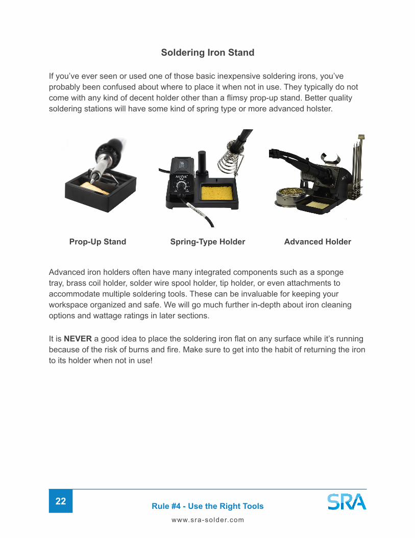
If you’ve ever seen or used one of those basic inexpensive soldering irons, you’ve probably been confused about where to place it when not in use. They typically do not come with any kind of decent holder other than a flimsy prop-up stand. Better quality soldering stations will have some kind of spring type or more advanced holster.
Advanced iron holders often have many integrated components such as a sponge tray, brass coil holder, solder wire spool holder, tip holder, or even attachments to accommodate multiple soldering tools. These can be invaluable for keeping your workspace organized and safe. We will go much further in-depth about iron cleaning options and wattage ratings in later sections.
It is NEVER a good idea to place the soldering iron flat on any surface while it’s running because of the risk of burns and fire. Make sure to get into the habit of returning the iron to its holder when not in use!
Prop-Up Stand Spring-Type Holder Advanced Holder

Rule #4 - Use the Right Tools23
www.sra-solder.com
Soldering Iron Tip Types
An important consideration in choosing a soldering iron is the actual tips it uses. After all, this is the part that will come in contact with your work. There are two main types that you will usually come across.
Regular Type
These standard tips are most commonly found on modern irons. They are partially hollow and slide onto the heating element of the iron. In order to replace them, the metal shield that protects the element must be removed first. These tips are great because they last a long time and are sometimes compatible across brands. Some models will use a set screw to keep the tip in place instead but they are often lower quality.
Cartridge Type
This second type is called a cartridge tip because it plugs directly into the handle of the soldering iron. The heating element is actually built into the body of the cartridge tip, making it considerably longer. The main advantages of this design are faster heating, better heat recovery, and the ability to hot swap tips while working. Soldering stations with cartridge tips will usually come with a heat-resistant rubber pad for swapping.
Rule #4 - Use the Right Tools24
www.sra-solder.com
Soldering Iron Tip Shapes
Both regular and cartridge type soldering iron tips are available in a variety of shapes and sizes. Some have as many as 50 different tip shapes for a wide range of soldering applications. These are the common groups you’ll see when purchasing tips but be aware, names and numbers can vary by manufacturer.
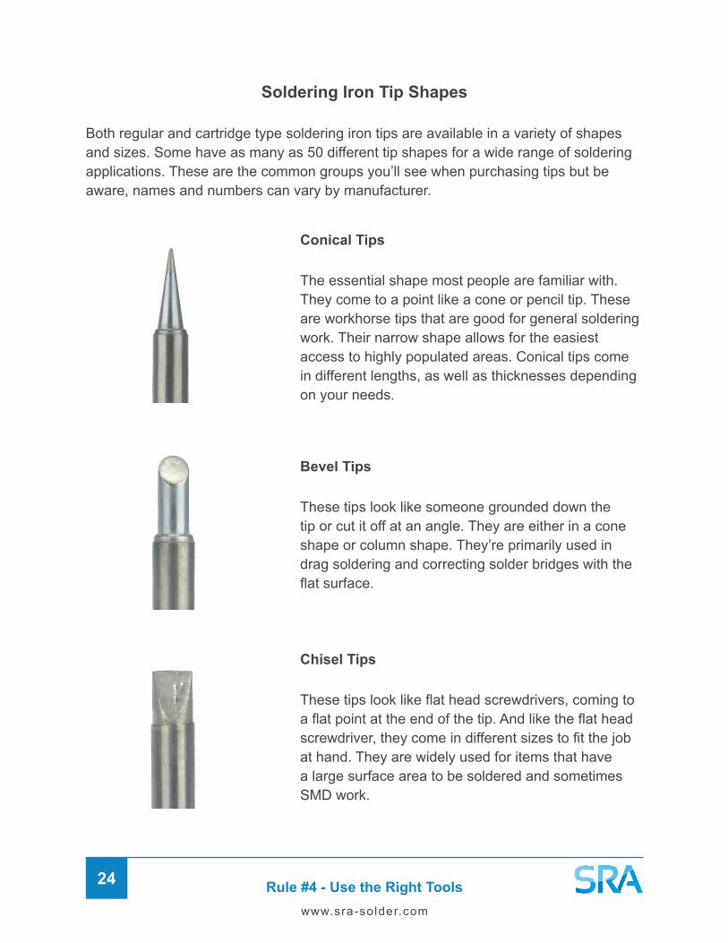
Conical Tips
The essential shape most people are familiar with. They come to a point like a cone or pencil tip. These are workhorse tips that are good for general soldering work. Their narrow shape allows for the easiest access to highly populated areas. Conical tips come in different lengths, as well as thicknesses depending on your needs.
Bevel Tips
These tips look like someone grounded down the tip or cut it off at an angle. They are either in a cone shape or column shape. They’re primarily used in drag soldering and correcting solder bridges with the flat surface.
Chisel Tips
These tips look like flat head screwdrivers, coming to a flat point at the end of the tip. And like the flat head screwdriver, they come in different sizes to fit the job at hand. They are widely used for items that have a large surface area to be soldered and sometimes SMD work.

Rule #4 - Use the Right Tools25
www.sra-solder.com
Special Tips
R/RT Tips - These tips have an opening in the middle to accommodate SMD components, like the 0805 size and smaller.
RB Tips - These tips have a small bend of about 30° very close to the end of the tip. It is used for drag soldering and the fixing of solder bridges.
H Tips - These tips have a smaller bend than the RB tips, about 25°, and are more of an oval shape. They are used in drag soldering and fixing soldering bridges.
J Tips – This tip style is much like a conical but with a curved bend at the tip. These are a secret weapon for SMD soldering work on small components.
K Tips - These look like the blade of a scalpel, or a hobby knife. It is used for narrow pitches, drag soldering, and fixing solder bridges.
1401/1403 - These tips are spatula/blade shaped meant for lead-free soldering. They are used for soldering multiple pins or leads at the same time, and reworking SMDs.
CM/BCM - These tips have a hollow bowl at the end of the tip to make drag soldering easier to solder the leads of surface-mount IC chips.

Rule #4 - Use the Right Tools26
www.sra-solder.com
Wet Cellulose Sponge
The wet sponge is the most common method of tip cleaning. It is standard issue on almost every soldering station out there.
þ Cost-effective
þ Highly-efficient at cleaning flux acids
þ Sponge can be cleaned for extended use
ý Momentarily drops tip temperature
ý Thermal-shock from water can shorten tip life
Tools for Cleaning
Abrasive Brass Coils
This waterless method of cleaning uses soft brass coils to remove solder from the tip quickly without dropping temperature.
þ Fairly inexpensive
þ No risk of thermal-shock to the iron
þ Indent on enclosure for resting iron (some models)
ý Doesn’t clean as well as water
ý Although soft, it can still shorten tip life

Rule #4 - Use the Right Tools27
www.sra-solder.com
Tools for Desoldering
Tools for Tinning
Desoldering Wick or Braid
A desoldering wick is simply a roll of copper mesh that is infused with flux. Usually it is either a rosin or no-clean type flux and when heated it draws the solder out of the joint. The solder wick is best used on SMD components and joints with little solder to remove.
Manual Desoldering Pump
If you’ve got a lot of solder to remove, the desoldering pump or “solder sucker” is a must. When the plunger is engaged, a vacuum is created. The heat resistant teflon tip can then be placed at the joint and when the button is pressed, it sucks the molten solder right out. The design is semi self-cleaning but they do get jammed and must be cleaned out before continuing.
Tip Tinner
Tip Tinner is a compressed tablet that contains a mixture of solder and oxide reducing compounds. Used for safe cleaning and re-tinning of oxidized soldering iron tips. It is preferred over solder wire because it does not contain any harmful flux acids that can reduce the life of your tip and is less wasteful. Tinning is discussed in-depth at rule #9.

Rule #4 - Use the Right Tools28
www.sra-solder.com
Tools for Wire Stripping
One of the most crucial skills to master before soldering wires is cleanly stripping the insulation. There are a few different methods you can use depending on preference.
Utility or Hobby Knife
A simple but effective tool for stripping wire. Used to carefully score around the wire insulation, making sure not to cut too deep. These also come in handy for removing heat shrink and working with coax cable.
Finger Wire Stripper
A step up from the hobby knife but similar idea. The jaw holds the wire in the appropriate groove and allows you to score around the insulation using your finger through the loop. These work great for larger shielded cables.
Manual Wire Stripper
The manual wire stripper is our favorite tool for several reasons. It’s cheap, it gives you a lot of control and flexibility, and it works great! There are basically two versions you will come across. Some have just open jaws with no markings and others have several indents for specific wire gauges. If you know the wire gauge, the marked ones are great because you know it won’t cut too deep. However, the basic type can handle most gauges as long as you’re careful. Just bite down on the insulation and twist around the wire. With the insulation still in the jaws, pull up to remove.
Pro Tip: Wire strippers work a bit better for you when they have dulled a bit. The sharpness of a new pair can cut through the insulation too easily, leaving you with broken conductors.

Rule #4 - Use the Right Tools29
www.sra-solder.com
Other Helpful Tools
Flush Cutters
Once your parts are soldered in place, the leads will usually have to be snipped. This ensures they will not touch other metal surfaces and short out connections. A quality pair of flush cutters will allow you to get right where you need them. A must for zip ties!
Needle-Nose Pliers
Needle-nose pliers come in handy for shaping component leads and placing parts where they need to go. Our favorite type are the ones with serrated jaws for better grip. We will talk about lead forming at Rule #12.
Automatic Wire Stripper
If you have to make a ton of wires and repeatability is a factor, these could be your best choice. The automatic strippers take the guess work out for you. It is also less fatigue on your hands and joints. There are also thermal wire strippers that use heat to cleanly remove the insulation.
Rule #4 - Use the Right Tools30
www.sra-solder.com
Parts Bins
No matter what kind of project you’re doing, you’ll want to keep track of all your parts and progress. We recommend having several plastic containers of varying sizes for organizing and storing parts during disassembly and new builds. There are ESD safe parts bins available as well for static sensitive components. Scrap pieces of cardboard can also come in handy for creating “templates” by sticking parts through it, especially keeping track of screws! In many cases, cardboard can make an excellent “solder buddy” to hold parts while soldering too.
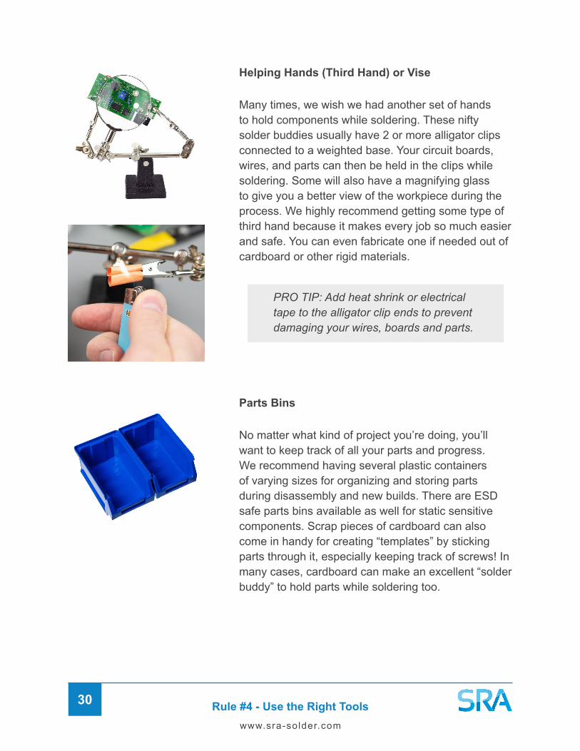
Helping Hands (Third Hand) or Vise
Many times, we wish we had another set of hands to hold components while soldering. These nifty solder buddies usually have 2 or more alligator clips connected to a weighted base. Your circuit boards, wires, and parts can then be held in the clips while soldering. Some will also have a magnifying glass to give you a better view of the workpiece during the process. We highly recommend getting some type of third hand because it makes every job so much easier and safe. You can even fabricate one if needed out of cardboard or other rigid materials.
PRO TIP: Add heat shrink or electrical tape to the alligator clip ends to prevent damaging your wires, boards and parts.

Rule #4 - Use the Right Tools31
www.sra-solder.com
Lighting
There’s no use in trying to solder something if you can’t see what you’re working on! Having a decent source of light on your workbench will be one of the best investments you ever made. The task lights that swivel are perfect for positioning exactly where you need light.
Inspection Visor or Microscope
Many techs will also use magnifying inspection visors with built-in lights or digital microscopes that allow them to get right over the target area.
Digital Camera
During tear-down and assembly, your best friend is definitely your smartphone or digital camera. We recommend taking lots of pictures throughout each step, you’ll be glad you did later! Trust us.

Rule #5 - Practice Soldering Safety32
www.sra-solder.com
Rule #5 – Practice Soldering Safety
When it comes to soldering there are few safety concerns that must be addressed. First, working with temperatures of up to 840°F (449°C) introduces risk for burns and fires. Second, electronic devices inherently present a risk of electrical shock. And finally, the soldering process itself produces fumes that are hazardous to breathe in. Don’t worry though, as long as you know the risks, you can mitigate them by working safely!
Fume Extractors (Smoke Absorbers)
The number one safety precaution to take when soldering is doing so in a well-ventilated space such as next to an open window where air can circulate. In any case, we recommend using a stand-alone fume extractor or one integrated into the iron to redirect fumes. Whether it be burning flux or plastic, the fan will pull the fumes through its carbon filter and get them away from your face.
Soldering Mats
As part of your setup, we also recommend using a heat-resistant rubber mat to protect your work area from any burns and scratches. Residue and debris from molten solder, component leads, sharp surfaces, and chemicals can wreak havoc on your workbench. A nice soldering mat will stop all this from ruining your table, so it’s a great thing to have. It will also help keep your components from rolling into the black abyss of the ground. There are also ESD safe mats to protect sensitive components from static charges that are naturally generated.

Rule #5 - Practice Soldering Safety33
www.sra-solder.com
WARNING: Risk of Electrical Shock
Finally, please be aware of the risk for lethal shock when working on electronic devices. Make sure power to the device is off and the power cable is physically unplugged from the outlet before opening anything. It is also important to drain any electrolytic capacitors before soldering because these can hold an electrical charge long after the device has been unplugged.
What is ESD?
Electrostatic Discharge or ESD is a surge of electricity from one object to another. This can occur when a higher charged object nears or makes contact with a lower charged object, thus creating a statically charged surge.
Friction can cause static electricity to build up in an object and transfer it to another object. Some electronics components are highly sensitive to ESD and are damaged easily by it, so using ESD safe tools and equipment will mitigate the risk.

Rule #5 - Practice Soldering Safety34
www.sra-solder.com
Leaded Solder Exposure
Please note that when using leaded solder alloys, the risk of lead exposure is only through touch. Lead does NOT vaporize (fume) at normal soldering temperatures and the fumes created by soldering are actually caused by the flux in the wire being burned off. Even though the smoke does NOT contain lead, it is still not good to breathe in and should be avoided.
Gloves
Using leaded solder is like handling raw meat. You should avoid contamination as much as possible and always wash your hands when done soldering. Especially if you’re actually going to handle food! We recommend wearing gloves when possible to minimize exposure of lead and other chemicals on your skin. It will also make clean up a bit quicker. The only downside is that it may be difficult to work with them in precise operations. Whether you use gloves or not, stay cognizant of what you’re touching throughout the process and wash your hands after.
Protective Eyeglasses
The threat of getting something in your eye is greater than you would think when soldering. The most obvious reason for protective eyewear would be to prevent fumes from getting in your eyes. However, other dangers like accidental splashes of hot solder, flying component leads, trimmed zip ties, and wire insulation can cause some serious damage too.

Rule #6 - Understand the Art of Heat Transfer35
www.sra-solder.com
Rule #6 – Understand the Art of Heat Transfer
Earlier we discussed methods for heat transfer but let’s now take a look at the many factors that affect it when hand soldering. Start by taking a look at your project and visualizing the outcome you want to accomplish. Analyze the components, specifically their size and makeup. Are they fragile or tough, plastic or metal, big or small? Do they have moving parts like a potentiometer or are they solid? These answers will help inform your approach because they all affect heat transfer in one way or another.
The goal of soldering is two-fold. First, to get in and out as quickly as possible to prevent damage to components you’re working with. Second, to make a proper mechanical and electrical connection at the joint.
Managing the Heat Cycle
To do this, you must be able to manage the “heat cycle”. Which is simply how quickly the joint heats up, how hot it gets, and how long it stays at that temperature. This is critical because heat along with pressure are the two main causes of damage to circuit boards. Both can easily cause the copper pads and traces on the board to lift, leading to a much more difficult and frustrating repair. However, one must also not be afraid of the heat because it is crucial to a successfully soldered joint. Taking it away too soon or “playing paintbrush” with the iron can lead to cold solder joints where the connection did not get hot enough for wetting to occur.
The soldering iron is not a paint brush, it must be held on the joint until a proper connection has been made.
The time you spend on a joint is referred to as the “dwell time” and it can vary based on a variety of factors. In the coming sections, we’re going to touch on everything that affects heat transfer from tip temperature to tip size. Understanding this will help you master the heat cycle and make the difference between a novice and professional solderer. I’ll be referring back to these concepts frequently because they help inform basically all decisions of what tools and techniques to use while soldering.

Rule #7 - Use the Right Temperature36
www.sra-solder.com
Rule #7 - Use the Right Temperature
You may be thinking that tip temperature is the most critical factor for heat transfer but this is actually not the case! While it is important, it’s only one piece of the heat management puzzle. The iron must be hot enough to melt the solder alloy you’re using but not too hot as to damage the components and board. Always check the specifications of your solder to make sure. The right temperature then becomes a balance between heating the joint quickly and allowing enough dwell time for the solder to wet into the joint.
For general electronics soldering, somewhere in the range of 572-662°F (300-350°C) is a good starting point. This can vary based on the size of the components and their makeup. For heating very large parts, you’ll likely want to be in the upper range or higher. Conversely, if the component is smaller or very heat-sensitive, you’ll want to stay in the lower range. Some soldering stations will have preset functions that allow you to jump between saved temperature settings depending on the work you’re doing.
Proper tip temperature is most critical for PCB work. As we said earlier, you really want to know how hot your iron is getting to properly manage the heat cycle and not damage the board. We highly recommend a soldering station with digitally controlled temperature for this type of work.
We don’t recommend cranking the temperature up to the highest it will go (Approx. 896°F / 480°C) because the tip will oxidize very quickly. If not careful, you can ruin the tip in a matter of minutes.
Heat Sinks
It may also be helpful to use a heat sink to stop some of the heat from getting to the component. Metal alligator clips or forceps (shown) make great heat absorbers that will hold the part as well. When a heat sink is added, the surface area that the iron must heat is increased; therefore giving you a longer dwell time.

Rule #8 - Keep Your Surfaces Clean37
www.sra-solder.com
Rule #8 - Keep Your Surfaces Clean
All surfaces involved in the soldering process must be free of contaminants and oxides before soldering. This means the surfaces of the work piece, components, and soldering iron tip. Remember that even the thinnest layer of oxides can prevent solder from sticking and wetting properly. Similarly, when you’ve got a dirty or highly oxidized tip, it’s just not going to transfer heat effectively.
The level of filth present will dictate how much cleaning you’ll need to do. For new builds with clean components, you can usually get by with just the flux-core in your solder wire and a well-maintained soldering iron. When reworking old or oxidized parts, you’ll want to clean them the best you can before soldering. To clean any foreign matter off of your component leads, wires, and solder pads, you can use a solvent like isopropyl alcohol, steel wool, fine sandpaper, or in some cases an ultrasonic cleaner if necessary.
Keeping Your Iron Tips Clean
There are two ways to clean your iron tip and they are wiping on a wet sponge or plunging into brass coils. There are pros and cons to both but we recommend using a hybrid approach for the best results and convenience. The semi-abrasive brass will get the bulk of the solder residue off without dropping tip temperature, while the sponge more effectively shocks away the acids from the flux.
If you’re still having trouble soldering after pre-cleaning the surface, you can try a more aggressive flux like RA or Water Soluble. Just remember to clean the flux residue off after because it is more corrosive.

Rule #8 - Keep Your Surfaces Clean38
www.sra-solder.com
How to Clean Using a Wet Sponge
Take a spray bottle filled with water and wet the entirely sponge but don’t drown it. An excess of water will drop the tip temperature too drastically, which will reduce the life of the tip because of the stress its under to recover from the heat loss.
1
2
3
To check for proper dampness, push down on the center of the sponge with your finger. If you get a pool of water, it is too damp and the excess should be dumped out before continuing.
You should usually hear a “Pssh” sound when cleaning. If you don’t, the iron may not be hot enough or the sponge not wet enough. A dry sponge will burn from the heat of the iron leaving black marks.
The best way to clean all sides of the tip is by making an “X” in two passes. First, drag the broad side of the iron across the sponge diagonally from the top of one side to the bottom of the other. Then make a half circle turn while keeping the same grip and drag across the sponge in the opposite direction to clean the other side of the iron tip.
Repeat if necessary until visibly clean and remember you don’t want to be poking the sponge with the tip of the iron, the whole surface should be making contact.
PRO TIP: Contamination of solder and flux residue built up on the sponge will start to affect your cleaning and tip. Periodically, you should dump out any solids and use both sides of the sponge until they are dirty. They should then be laundered or replaced.

Rule #8 - Keep Your Surfaces Clean39
www.sra-solder.com
How to Clean Using Brass Coils
PRO TIP: When there’s too much solder applied to your tip or you want to simply remove excess, you can flick it off into your sponge to remove quickly. Be careful of molten solder and wear safety protection.
1
2
3
Plunge the hot soldering iron into the brass coils but not too deep because you will hit the bottom of the container and risk damaging the tip.
When the solder and flux build-up start affecting cleaning, flip over the coils and use the clean side to extend its life.
To take it up a notch, you can twist the iron with your fingers while cleaning to help get all sides. Try not to keep jabbing the same spot, move around to disperse the solder and ensure effective cleaning.

Rule #8 - Keep Your Surfaces Clean40
www.sra-solder.com
Maximzing Tip Life
Please DO NOT use a file, scouring pad, or sandpaper to “clean” your tips. This practice dates back to when soldering tips were simply bare copper and needed to be occasionally reshaped.
When you file the plating off, you dramatically reduce tip life by compromising its ability to melt solder and for solder to stick to it. Once you get through the plating, you’ll have a hole in your tip and it will no longer work correctly.
Mechanical Force
Using the iron in an abrasive manner by applying force and pressure while soldering can ruin the tip. You shouldn’t have to apply any more pressure than the weight of the iron to the joint; let gravity do the work here.
Modern tips are plated for extended life and performance, making it unnecessary and actually very damaging. New soldering tips are constructed of a copper core that is then plated with iron, chromium, and nickel alloy for strength.

Rule #9 - Keep Your Tip Tinned41
www.sra-solder.com
Rule #9 – Keep Your Tip Tinned
The only way to keep your tips working perfectly and maximize their lifespan is to keep them properly cleaned and tinned. Tip tinning is the practice of adding solder or Tip Tinner (solder-like mixture) to the tip for protection and to achieve optimal heat transfer.
The expression “tinning” comes from the fact that solder was sometimes called tin in the early days of soldering. All solder is made of mostly tin with other metals and additives.
Pre-Tinning
Applying solder to the tip before soldering helps to jump start the heat transfer process, as the flux cleans the tip and gets the solder flowing before you even touch the joint. It also comes in handy in situations where you need one hand free. If the joint is small enough you can somethings solder it just by pre-tinning the iron. Other times you may add a little bit of solder to “tack” a component in place to make it easier to solder all the pins without it moving.
It is important to tin the tip before returning the iron to its holder as this will create a protective coating on the tip. The fresh Solder or Tinner forms a gas tight seal so oxidation caused by sitting in the open air is dramatically reduced.
Any solder residue that is left on the iron after coming off a joint should always be cleaned off because it includes other contaminants from the components and process. If the iron is smoking excessively in the holder that means there is a concentration of flux still on there that needs to be cleaned off. Again, flux acids will eat away at the plating on the tip, reducing its life.
How to Tin Your Tip
When using your iron for the first time, you will want to perform a renewing cycle of tinning and cleaning until the tip has a nice coating of fresh solder built up and accepts solder easily. Oxidation can form over night as well, so still do this at the start of each day before your soldering session for best results.

Rule #9 - Keep Your Tip Tinned42
www.sra-solder.com
Clean the iron on a wet sponge or brass coils several times to remove any surface oxidation.
Add a layer of solder or Tip Tinner all around the tip to coat it evenly.
Clean the tip off on the sponge or brass coils to remove excess solder, leaving behind a thin layer.
Now try to tin the tip with flux cored solder to see if it will accept it. If it does, you are done and can begin your work. If not, repeat these steps until it does.
2
3
4
5
Turn on the soldering iron and set it to around 608-662°F (320-350°C).1

Rule #10 - Pay Attention to Surface Mass43
www.sra-solder.com
Rule #10 - Pay Attention to Surface Mass
What we mean by this is the size and surface area of the parts being soldered but also of the iron tip itself. When choosing a soldering iron tip, you want to match the size to the work you’re doing. The shape is in part up to your preference but also what fits best into the joint and provides the greatest surface area for heating. In general, the shorter the tip is, the more efficient it will be because it is closer to the heating element and therefore more evenly distributed. The simple physics here is that larger components will take longer to heat when using small tips and vice versa.
Small Tip + Big Mass = Slow temperature rise Big Tip + Small Mass = Fast temperature rise
Most soldering irons will have interchangeable tips that can be quickly swapped out or replaced when worn out. There are two main types of tips which are the standard type that sit on the heating element and the cartridge type that plug into the iron handle. Cartridge type tips actually have the heating element built into their long body. The advantage is that they can be changed very easily while working. Both standard and cartridge tips come in many different shapes and sizes, each with their own purpose or application. The most common are the pointy shapes known as “conical tips” which are great all-around workhorses for general soldering use. When you’ve got bigger components or more surface area to heat “bevel tips” come in handy with their flat edge. Make the job easier and more efficient heat transfer.
Use the Contact Patch Advantage
The contact patch refers to the surface area between the iron tip and the joint while soldering. If you only use the very tip top of the soldering iron to solder, you will get poor heat transfer. By using the broad side, you increase the surface area or “contact patch” resulting in superior heat transfer. This means you can get in and out faster because you spend less time heating the joint.
In order to better understand this concept, try a dry run without heat so you can observe the surface areas that touch while soldering. Another masterful way to increase heat transfer is by using solder to expand the linkage. When you add solder wire between the iron tip and the joint you are adding mass to both. Not to mention the flux, that is cleaning the surfaces, aiding in the heat transfer and allowing the solder to stick.

Rule #10 - Pay Attention to Surface Mass44
www.sra-solder.com
Make Sure Your Iron is Powerful Enough
The job of every soldering iron is to generate and store heat. When you touch an iron to a mass such as a component or circuit board, it will start losing its heat. The larger the mass you’re trying to heat or the longer it sits there, the harder the iron must work to recover the heat loss. This is known as the rate of recovery and the heating capacity of the iron is measured by its wattage rating. In order to last longer and heat larger areas without dropping temperature, more wattage is needed.
Iron Wattage Explained
Having a higher wattage means that the iron has a larger heating element or “Thermal Bank” to draw from before the temperature starts dropping. In a worst-case scenario, the iron could actually get stuck to the work piece from being drained of its heat supply and allowing the solder to solidify.
Generally speaking, a basic AC voltage iron of around 40-60W is ideal for electronics. Anything higher wattage on a non-digitally controlled iron will get too hot to solder accurately. When the temperature is regulated by a microprocessor with a closed feedback loop, higher wattage ratings become an asset. This is because it will maintain your set temperature no matter how big the surface area is. Where higher wattage simply means more heating power in reserve to use if needed. This opens up the possibility of using anything from 40 to even 100 Watts for electronics no problem.
Basic 60 Watt Iron Digitally-Controllled 60W Iron

Rule #11 - Place Your Components Securely45
www.sra-solder.com
Rule #11 - Place Your Components Securely
Almost as important as soldering itself is how you install the components to be soldered. Everything should be installed neatly, securely, and in the proper orientation. Some parts are polarized with a defined positive and negative lead. If connected improperly they can get damaged or worse blow up your circuit.
General Component Installation Order
1� Sockets (Note Orientation)
6� LEDs (Note Orientation)
4� Electrolytic Capacitors
(Note Orientation)
9� Stranded Wire
5� Diodes (Note Orientation)
10� IC Chips (Note Orientation)
2� Resistors
7� Transistors
3� Capacitors < 1 Micro Farad
8� Solid Wire
Axial Versus Radial Leads
In terms of through-hole devices (THD), there are two types of lead configurations which are axial and radial. Axial leads run horizontally while radial leads run vertically.

Rule #11 - Place Your Components Securely46
www.sra-solder.com
How to Form Component Legs
The Art of Lead Forming
Sometimes out of the bin or box, your components can have bent or even mangled leads. When forming leads, it’s nice to start with the leads as straight as possible. Our favorite tool for this is long needle-nose pliers that have serrated jaws. An ESD Safe version doesn’t hurt either! To straighten a bent lead, grab the lead so the jaws of the pliers are right before the component body. Using your fingers, bend the lead back into shape. The edge of the plier will serve as your guide to straightening. If there are kinks in the middle of the lead, move the pliers to right before the bend and again use the edge to straighten the best you can. Alternatively, you can cut that part off as long as there will be enough of the lead left to solder on to.
Dry fit the component over the holes of the board or the desired points of contact. Ideally equi-distant between the two holes or terminals. Pick one lead and note the point where you want the bend to occur.
Mark the spot by grabbing the lead with your pliers. Try to get it right before the point you want the bend to occur because you must account for the bend and jaws of the pliers.
Using the hard edge of the pliers, bend the lead and flatten it against the edge to form a tight and professional bend.
1
2
3
Rule #11 - Place Your Components Securely47
www.sra-solder.com
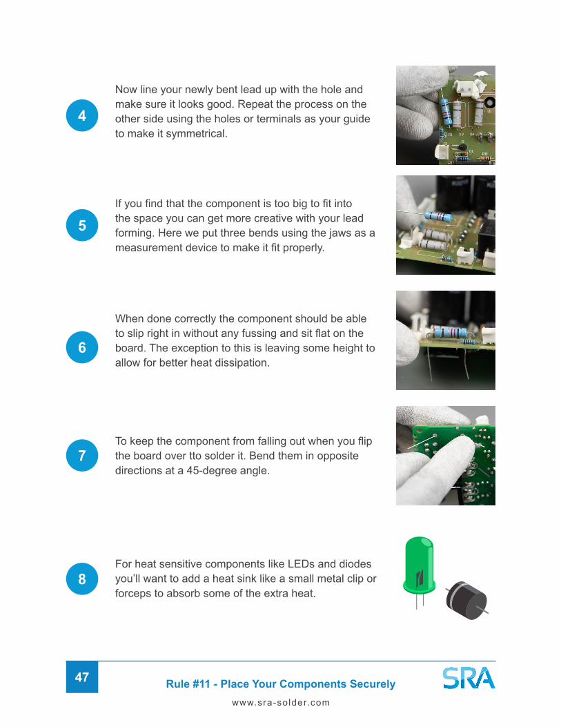
To keep the component from falling out when you flip the board over tto solder it. Bend them in opposite directions at a 45-degree angle.
For heat sensitive components like LEDs and diodes you’ll want to add a heat sink like a small metal clip or forceps to absorb some of the extra heat.
Now line your newly bent lead up with the hole and make sure it looks good. Repeat the process on the other side using the holes or terminals as your guide to make it symmetrical.
If you find that the component is too big to fit into the space you can get more creative with your lead forming. Here we put three bends using the jaws as a measurement device to make it fit properly.
When done correctly the component should be able to slip right in without any fussing and sit flat on the board. The exception to this is leaving some height to allow for better heat dissipation.
4
5
6
7
8

Rule #11 - Place Your Components Securely48
www.sra-solder.com
Tacking
To make it easier for rework (removing the part), you may want to leave the leads straight instead. A good way to do this is to hold the component in place with your pliers and use a pre-tinned iron tip to Tack the component. The idea is not to make a good solder connection, you’re just trying to keep it in place temporarily. With it held in place you can go solder the opposite side properly and then re-solder the tacked side.
Wrapping
Another way to keep leads in place on various through-hole terminals is by wrapping them around the terminal. This creates a much more robust mechanical connection but it will be much harder to desolder later if needed. You might have to cut it out if you can’t clear all the solder out without damaging the components. We recommend wrapping leads only if you know it’s staying there for a long time or there’s no other way to get it to stay in place while you solder.
How to Prepare IC Chips
When IC chips come fresh out of the package, the leads are at a specific pitch or angle and when you try to place it into the holes or socket, it will likely not fit.
To correct this, all you need is a flat hard surface to shape the pins. Hold the plastic body of the chip and place one side on your hard surface.
Now carefully roll the chip to straighten the pins between the body of the chip and hard surface. Do the same to the other side and then the chip should fit into the holes nicely.
When the pins on a chip or chip socket become bent it can be very difficult to straighten without breaking them. You can try using your fingers or pliers to do this as described before.

Rule #12 - Add Solder and Heat Simultaneously49
www.sra-solder.com
Rule #12 – Add Solder and Heat Simultaneously
Now comes the time to finally solder our first connection! Many guides teach soldering in such a way that is NOT conducive to the fastest heat transfer possible. They will often tell you to apply the iron at the joint and hold for 1-2 seconds. Then add solder from the opposite end, making sure to not touch the iron, and when the solder starts melting you know the joint has reached temperature. The problem with this approach is that it takes too long to heat the joint, so you run a greater risk of damage due to overheating. Instead, we recommend adding the solder and heat at the same time, which will kick start the heat transfer process.
Take up the solder spool about 2-3 inches from the end. This gives you enough wire to work with without getting burnt and allows for better control over it.
How to Solder Through-Hole Components
Turn on the soldering iron and set it between 572-662°F (300-350°C). Turn on your fume extractor if you have one. Assemble all your parts on the bench.
When your iron gets up to temperature clean and tin it. Remember to always tin your tip before and after soldering. If the tip remains dry without solder during storage, you will greatly reduce the life of the tip.
1
2
3
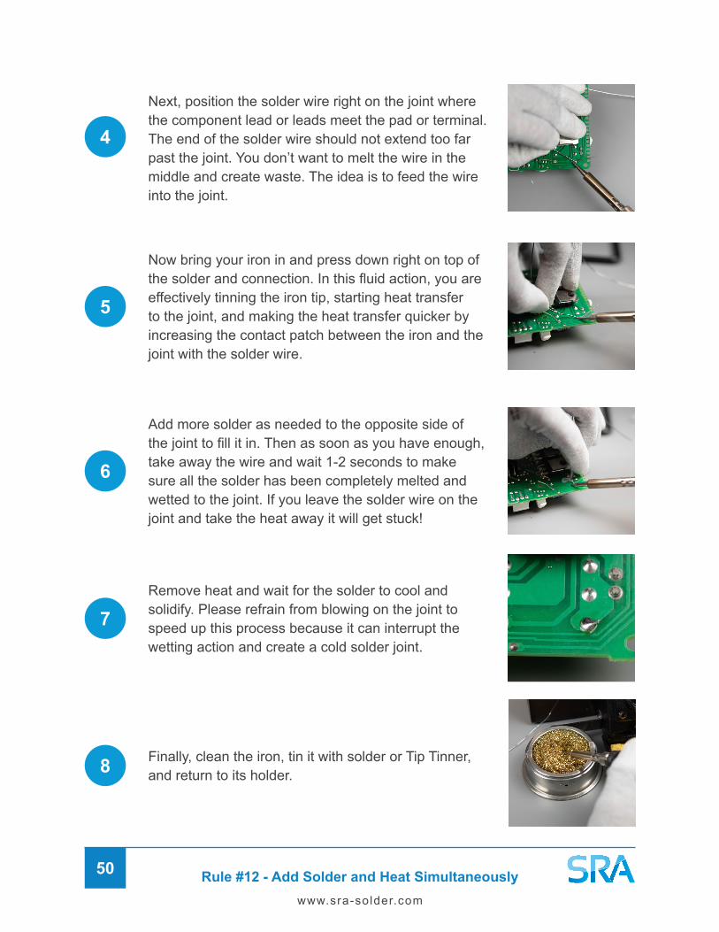
Rule #12 - Add Solder and Heat Simultaneously50
www.sra-solder.com
Next, position the solder wire right on the joint where the component lead or leads meet the pad or terminal. The end of the solder wire should not extend too far past the joint. You don’t want to melt the wire in the middle and create waste. The idea is to feed the wire into the joint.
Add more solder as needed to the opposite side of the joint to fill it in. Then as soon as you have enough, take away the wire and wait 1-2 seconds to make sure all the solder has been completely melted and wetted to the joint. If you leave the solder wire on the joint and take the heat away it will get stuck!
Now bring your iron in and press down right on top of the solder and connection. In this fluid action, you are effectively tinning the iron tip, starting heat transfer to the joint, and making the heat transfer quicker by increasing the contact patch between the iron and the joint with the solder wire.
4
5
6
7
8
Remove heat and wait for the solder to cool and solidify. Please refrain from blowing on the joint to speed up this process because it can interrupt the wetting action and create a cold solder joint.
Finally, clean the iron, tin it with solder or Tip Tinner, and return to its holder.

Rule #12 - Add Solder and Heat Simultaneously51
www.sra-solder.com
How to Solder Wires
Soldering wires is a great place to start with soldering because it is much more forgiving than circuit boards. You can spend a bit longer heating wires than PCBs but overheating is still a danger. The main concern is melting the insulation because it could potentially expose the bare wires in your circuit. This presents a shock hazard and possible cause of shorts in your device. Additionally, melted plastic doesn’t smell very good and is harmful to inhale!
The world of wires gets quite vast when you starting to look at different connector types and cables that can be created with them. There’s too many types of connectors to go over in a general soldering guide so we will focus on the skills that will be useful in all applications. Then we will show how to do some specific methods for soldering wires together. All of which use similar soldering techniques. What differs is the mechanical connection made by twisting or wrapping the wires together.
Solid and Stranded Wire
The two most common types of wires found in electronics are solid and stranded. Solid wire has a single conductor whereas stranded has many smaller conductors that make up a single wire. Stranded wire is more flexible than solid wire but the individual strands are easier to break. There is also braided wire, which is tightly laced strands used primarily for shielding in long runs of cable.
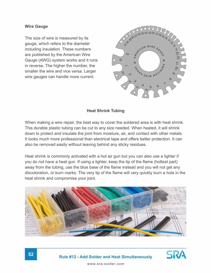
Rule #12 - Add Solder and Heat Simultaneously52
www.sra-solder.com
Wire Gauge
The size of wire is measured by its gauge, which refers to the diameter including insulation. These numbers are published by the American Wire Gauge (AWG) system works and it runs in reverse. The higher the number, the smaller the wire and vice versa. Larger wire gauges can handle more current.
Heat Shrink Tubing
When making a wire repair, the best way to cover the soldered area is with heat shrink. This durable plastic tubing can be cut to any size needed. When heated, it will shrink down to protect and insulate the joint from moisture, air, and contact with other metals. It looks much more professional than electrical tape and offers better protection. It can also be removed easily without leaving behind any sticky residues.
Heat shrink is commonly activated with a hot air gun but you can also use a lighter if you do not have a heat gun. If using a lighter, keep the tip of the flame (hottest part) away from the tubing, use the blue base of the flame instead and you will not get any discoloration, or burn marks. The very tip of the flame will very quickly burn a hole in the heat shrink and compromise your joint.
AM
ERICAN WIRE GAUG
E
AM
ER I C A N W I R E G AUG
E

Rule #12 - Add Solder and Heat Simultaneously53
www.sra-solder.com
Wire Stripping
Using your wire strippers of choice, bite down on the insulation lightly to grip the insulation. Close down on the wire just enough to slightly pierce the insulation. This will come with experience for you to get a feel for it.
It will likely pierce the bottom of the wire first and not the top but the idea is to cut through the insulation all the way around.
Score the wire by twisting the wire strippers around. With the jaws still locked on the insulation, squeeze a little bit and, pull up to remove the insulation cleanly.
If you are having trouble, you might be trying to remove too much at once so in this case strip a smaller piece first and then finish it.
Be careful not to break any of the conductors inside the wire. If you do, you should cut it off and try again.
Pre-Tinning Wires
Just as tinning your tip helps with heat transfer, pre-tinning wires before soldering can help speed up the soldering process by cutting down on dwell time. Pre-tinning can be done with a solder pot for higher production runs or with an iron and solder wire. In the case of stranded wires, it also keeps them together if you need to insert it into a terminal.

Rule #12 - Add Solder and Heat Simultaneously54
www.sra-solder.com
Rat-Tail or Twist Splice
The rat-tail splice, also called a twist splice or pig-tail splice is done by simply twisting two or more bare wires together. It is used frequently in home electrical but much less common in electronics because it is not very reliable. It is best used for short term connections that may have to be changed in the near future. Electricians will often twist the wires together and secure them with a wire nut in receptacles.
Strain Reliefs
Wires and cables are usually subject to a lot of abuse from being plugged and unplugged and pulled on. In order to reduce these weak points in wires, strain reliefs are used. There are many different kinds of strain reliefs you will come across. For example, equipment that has a hardwired power cord will always have a chassis strain relief to prevent anything from being disconnected and shorting out within the unit.

Rule #12 - Add Solder and Heat Simultaneously55
www.sra-solder.com
How to Make a J-Hook Connection
When working with solid core wire, one of the easiest ways to connect two wires together is interlocking J-hooks.
1
2
3
4 Bring the two wires together by hooking the ends on each other.
Strip the wire insulation equally on both wires. With cloth covered wire all you need to do is pull back on the insulation to reveal the conductor. Otherwise appropriate wire strippers are needed.
Using a pair of needle-nose pliers, come down a quarter of the way on the exposed wire and bend the wire around to form a “J” shape. Repeat step on second wire.
Cut a piece of heat shrink tubing that will cover the exposed wires and a bit of insulation on each side. Slide the tubing down one of the wires for later.

Rule #12 - Add Solder and Heat Simultaneously56
www.sra-solder.com
5
6
7
8
Press the ends of the wire down with your fingers to pliers to form a solid mechanical connection.
Solder the connection. Use the broad side of the iron to heat up the joint. Apply solder at the same time to speed up heat transfer and fill joint.
Slide the heat shrink over the newly soldered connection so it is completely covered.
Using a lighter or heat gun, shrink the tubing down on the connection.
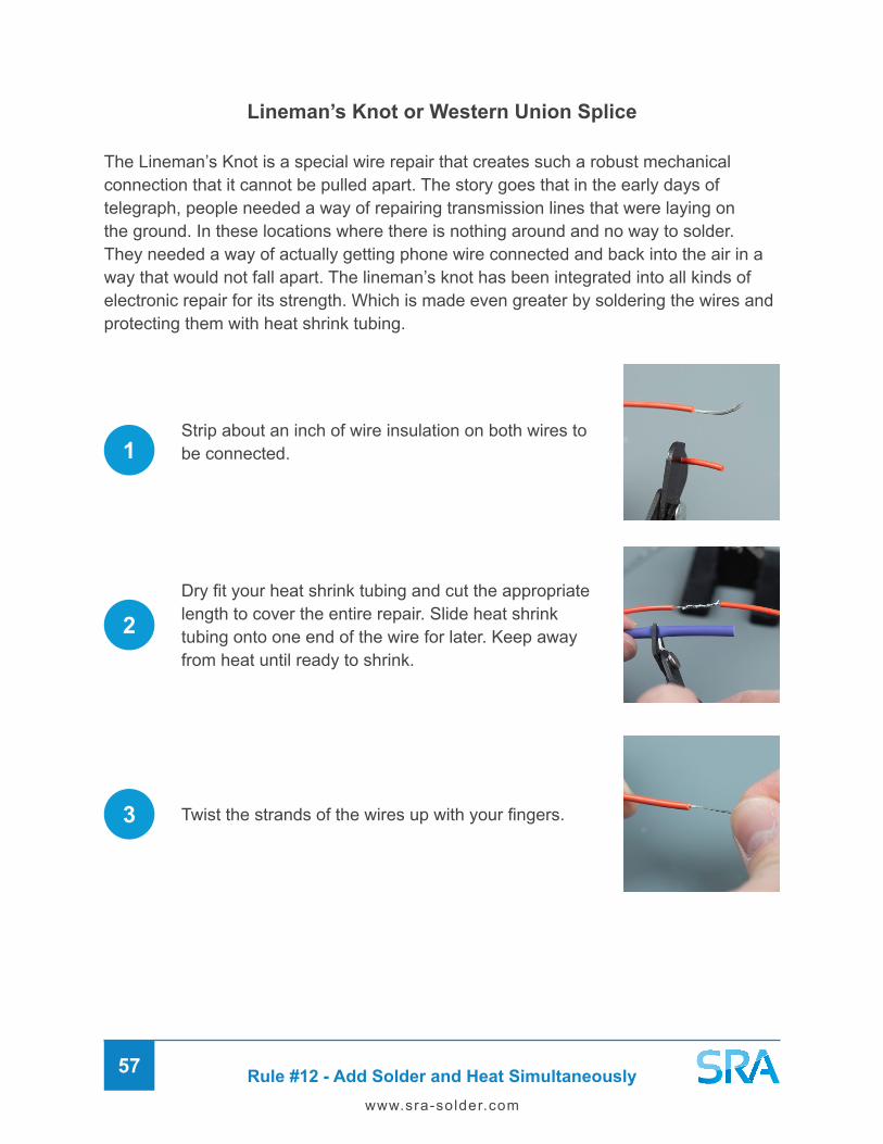
Rule #12 - Add Solder and Heat Simultaneously57
www.sra-solder.com
Lineman’s Knot or Western Union Splice
The Lineman’s Knot is a special wire repair that creates such a robust mechanical connection that it cannot be pulled apart. The story goes that in the early days of telegraph, people needed a way of repairing transmission lines that were laying on the ground. In these locations where there is nothing around and no way to solder. They needed a way of actually getting phone wire connected and back into the air in a way that would not fall apart. The lineman’s knot has been integrated into all kinds of electronic repair for its strength. Which is made even greater by soldering the wires and protecting them with heat shrink tubing.
Strip about an inch of wire insulation on both wires to be connected.1
2Dry fit your heat shrink tubing and cut the appropriate length to cover the entire repair. Slide heat shrink tubing onto one end of the wire for later. Keep away from heat until ready to shrink.
Twist the strands of the wires up with your fingers.3

Rule #12 - Add Solder and Heat Simultaneously58
www.sra-solder.com
Come up from insulation about a 1/3 of the way and put bend in both wires. Put the bent wires together and bend them back on themselves
You should get a couple of wraps by wrapping them both in opposite directions.
4
5
6
Now you’re ready to solder the wires. You can use a flux core solder only or coat the wires with a rosin flux paste to make it easy and solid.
Slide the heat shrink over the repaired area and make sure it covers completely. Use a heat gun or lighter to shrink the tubing down on the wires. Use the base of the flame to avoid damaging anything.

Rule #13 - Inspect and Evaluate the Joint59
www.sra-solder.com
Rule #13 – Inspect and Evaluate the Joint
The Ideal Solder Joint
You should now have a perfectly formed joint with the solder vacuumed (wetted) down into a cone shape on the component lead. The finished joint should be bright and shiny chrome in appearance if a leaded alloy was used. For lead-free, it will look more satin in appearance opposed to shiny.
Common Soldering Errors
If your joint did not come out as expected, don’t worry you can always try again! Sometimes a joint can look ugly but still be a fine connection, other times it is unreliable and should be fixed. Let’s go over some common soldering errors.

Rule #13 - Inspect and Evaluate the Joint60
www.sra-solder.com
Cold Solder Joint / Dry Solder Joint
- The solder did not get hot enough to melt completely and for proper wetting to occur. This can happen on the component pin or lead, on the pad or terminal, or both.
Appearance: Rough surface with possible holes
Insufficient Wetting on Pin or Lead
Insufficient Wetting on Pad or Terminal
Insufficient Wetting on Both
How to Fix: Heat the joint longer or turn up the temperature. Add more flux if needed and be sure to not move the component.
Not Enough Heat

Rule #13 - Inspect and Evaluate the Joint61
www.sra-solder.com
Overheated Solder Joint
The most common result of overheating is discoloration and burn marks on the circuit board. For wires, the insulation can recede backwards. You can tell if the jacket looks very shiny, this is a tell-tale sign the wire got too hot.
Crack due to vibration, liquid solder has no strength
Too Much Heat
Lifted Pad
The worst-case scenario when working with a circuit board is a lifted pad. This is where the trace got so hot that it lifted right off the board. This is very difficult to fix and you might end up having to run a wire to make the proper connection again. Which looks unprofessional and is not as reliable. Beyond the scope of this guide. Easiest fix would be a jumper wire.
Balance of time and temperature, can damage components and board.
How to Avoid Overheating
• Don’t apply pressure to the board or parts when soldering.
• Pay attention to the heat cycle, get in and out quickly.
• Add more flux to the joint or pre-tin the tip to speed up heat transfer

Rule #13 - Inspect and Evaluate the Joint62
www.sra-solder.com
Solder Blob
When an excess of solder is fed into the joint, you will get a build-up of solder on the joint that cannot wet down into a cone shape simply because there is too much material and so little space.
Solder blobs also make it difficult to confirm if the solder actually wetted down into the joint.
To fix this, use a wick or pump to remove excess solder. Alternatively, you may be able to heat it up and catch the excess on your iron tip which can then be wiped off on brass or wet sponge.
Solder Bridge
Another common soldering error due to too much solder is the solder bridge. This is when solder is accidently spread across multiple pins or terminals, connecting them electrically. A solder bridge can cause a dangerous short and ruin your components or project.
Shorts can also be caused by untrimmed component leads so make sure they are neatly cut before reassembling.
Too Much Solder
Sometimes when solder doesn’t want to stick to one side of a plated through-hole you can keep adding solder but it flows to the other side forming a solder blob. In this case you would need to clean the suspect side better and try adding more flux to get it flowing.

Rule #13 - Inspect and Evaluate the Joint63
www.sra-solder.com
Not Enough Solder
Solder Tunnel
Visible hole or gap in the solder joint.
Missed Joint
The connection was never soldered during the manufacturing process.
Tacked Joint
Component was tacked to keep it in place but operator forgot to solder a proper joint later.

Rule #13 - Inspect and Evaluate the Joint64
www.sra-solder.com
Moved Component
Disturbed Joint - If the component moves for any reason during the soldering process, it will compromise the reliability of the joint. Components should be stationary and secured (Rule #11) when heating and especially when cooling.
Solder Spike
The iron was withdrawn too slowly causing a projection from the solder joint.
Solder Ball
The iron was withdrawn too fast or the wrist was twisted.

Rule #14 - Desolder If Necessary65
www.sra-solder.com
Rule #14 - Desolder If Necessary
The Manual Desoldering Pump
The manual desoldering pump is an excellent and cost-effective solution for removing a lot of solder at once. Using your non-dominant hand, grip the pump with your middle, ring, and pinky fingers just below the trigger button.
Your index finger should sit right above resting over the button and your thumb free to depress the plunger) This way you can operate the pump with one hand and have the other free for your iron.
Before heating the joint, be sure that the desoldering pump is not clogged by firing it off a few times. Be aware that dry solder remnants may splatter everywhere so ideally do this over a trash can or similar. If you hold the plunger down you should see the rod coming out from the nylon tip. If the suction doesn’t seem right, open the barrel and clean out any solder remnants in there.
The desoldering pump can generate static charge and should not be used on very static-sensitive components like CMOS and MOSFET chips.
Put the pump aside but close for now and locate the component to be desoldered. For through-hole devices it sometimes helps to apply pressure with one finger to the component and feel for it on the other side to locate the pins. You could also use a continuity tester on your multi-meter to help find the part. Mark the solder pads with a sharpie so you are absolutely sure before desoldering.
The goal with desoldering is to get the solder in the joint molten as quickly as possible so you can suck it out without damaging anything.
If you’ve found that your solder joint is not quite up to par, you may need to remove some solder to try again. Also, if you accidently installed the wrong part or damaged one of your components, you will have to desolder. There are three ways you can go about removing solder which we will now cover.
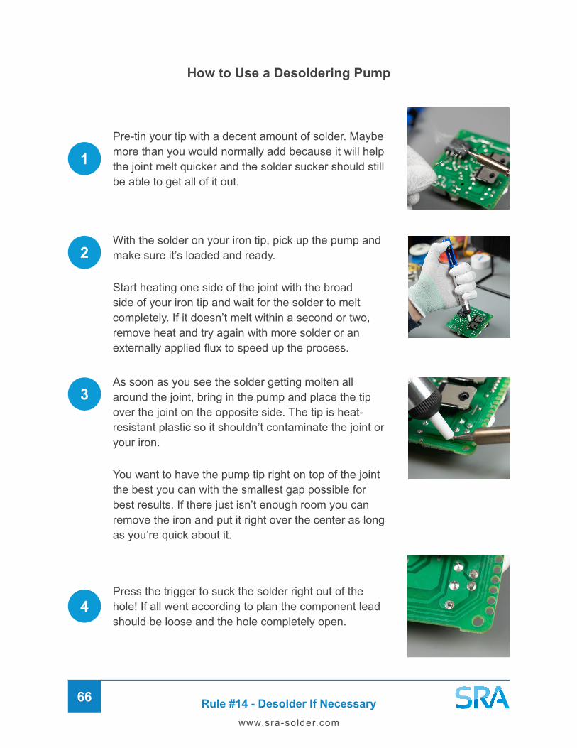
Rule #14 - Desolder If Necessary66
www.sra-solder.com
Pre-tin your tip with a decent amount of solder. Maybe more than you would normally add because it will help the joint melt quicker and the solder sucker should still be able to get all of it out.
How to Use a Desoldering Pump
Press the trigger to suck the solder right out of the hole! If all went according to plan the component lead should be loose and the hole completely open.
As soon as you see the solder getting molten all around the joint, bring in the pump and place the tip over the joint on the opposite side. The tip is heat-resistant plastic so it shouldn’t contaminate the joint or your iron.
You want to have the pump tip right on top of the joint the best you can with the smallest gap possible for best results. If there just isn’t enough room you can remove the iron and put it right over the center as long as you’re quick about it.
With the solder on your iron tip, pick up the pump and make sure it’s loaded and ready.
Start heating one side of the joint with the broad side of your iron tip and wait for the solder to melt completely. If it doesn’t melt within a second or two, remove heat and try again with more solder or an externally applied flux to speed up the process.
1
2
3
4
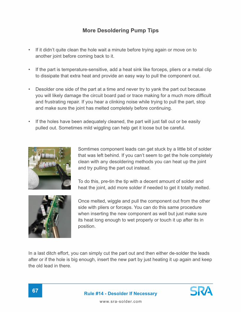
Rule #14 - Desolder If Necessary67
www.sra-solder.com
Somtimes component leads can get stuck by a little bit of solder that was left behind. If you can’t seem to get the hole completely clean with any desoldering methods you can heat up the joint and try pulling the part out instead.
To do this, pre-tin the tip with a decent amount of solder and heat the joint, add more solder if needed to get it totally melted.
Once melted, wiggle and pull the component out from the other side with pliers or forceps. You can do this same procedure when inserting the new component as well but just make sure its heat long enough to wet properly or touch it up after its in position.
More Desoldering Pump Tips
• If it didn’t quite clean the hole wait a minute before trying again or move on to another joint before coming back to it.
• If the part is temperature-sensitive, add a heat sink like forceps, pliers or a metal clip to dissipate that extra heat and provide an easy way to pull the component out.
• Desolder one side of the part at a time and never try to yank the part out because you will likely damage the circuit board pad or trace making for a much more difficult and frustrating repair. If you hear a clinking noise while trying to pull the part, stop and make sure the joint has melted completely before continuing.
• If the holes have been adequately cleaned, the part will just fall out or be easily pulled out. Sometimes mild wiggling can help get it loose but be careful.
In a last ditch effort, you can simply cut the part out and then either de-solder the leads after or if the hole is big enough, insert the new part by just heating it up again and keep the old lead in there.

Rule #14 - Desolder If Necessary68
www.sra-solder.com
How to Use a Desoldering Wick
When using a wick, do NOT pre-tin the iron tip because the wick will just suck it up and be wasted.
Place the wick right over the joint and press the broad side of the dry soldering iron tip against it.
When you see that the wick is full of solder remove both it and the heat at the same time to avoid the braid getting stuck to the joint.
If the hole is not sufficiently cleaned, clip off the used part of the wick and try again.
How to Use a Vacuum Desoldering Gun
Great for clearing through-holes and removing large components. Typically not good for SMD.
Solder removal gets trickier as component sizes get smaller. Surface-mount parts with leads that are hidden underneath or closely populated need special treatment. If you have space to get a soldering iron around all the leads without damaging anything than you could try Fast Chip removal alloy and its special flux. The low-temperature alloy keeps the solder in a molten state long enough to get around the hole chip and remove it with tweezers to suction.
If not, a hot air rework station and solder paste is your best bet. Hot air guns have nozzles tips that are designed for soldering the exact package size you’re working with.

Rule #15 - Clean Up Your Mess69
www.sra-solder.com
Rule #15 - Clean Up Your Mess
We’ve made it to the last step, clean up! You can clean as you go or wait until the end of your project. The first thing you should do after verifying your solder joint is successful is trim any long component leads sticking out.
Trim Your Leads
Trim any protruding leads with flush cutters so you have just a little bit visible above the solder cone. Make sure there aren’t any solder remnants left in your device because these could cause a short later. Hold the lead or cup your hand around it when cutting so it doesn’t fall in. You can also get pliers with a lead retainer that will catch the lead for you after cutting.
Clean Flux Residues
Depending on the type of flux used you may want to clean residue left over off the board. No-clean and Rosin-based fluxes generally do not need to be cleaned off after soldering. However, any inorganic fluxes with aggressive acids will require cleaning to prevent corrosion. We recommend using either isopropyl alcohol or lacquer thinner to make your board look squeaky clean. Alternatively, you could use an Ultrasonic Cleaner as long as all the parts on the board are sealed from moisture. There are special cleaning solutions for use with circuit boards called Saponifiers.

Final Thoughts70
www.sra-solder.com
Final Thoughts
Thank you for reading our electronics soldering guide. In these 15 steps, we first covered the fundamentals and reasons for soldering. As well as how to identify construction methods and choose the right tools for the job. These foundational skills will help you go into any soldering job with confidence that a favorable outcome is possible.
Next, we discussed the art of heat transfer and the importance of managing temperatures, keeping all surfaces clean, tinning your tip, and paying attention to surface mass. The balance between heat, surface mass, and cleanliness is the key to making successful solder joints every single time.
We then learned how to place components securely and maximize heat transfer by using the broad side of the iron. Applying the heat with solder simultaneously allows for quick and efficient heat transfer. Which reduces the risk of damage by overheating the parts.
Finally, we showed you how to spot an ideal soldering joint and prevent common soldering errors. Knowing what to look for is a crucial skill to ensure every joint is perfectly formed before moving on. Remember, if something goes wrong you can always desolder and try again! Once the soldering is completed, all that’s left is to clean up, test, and assemble the project.
Congratulations, you are now a certified SRA Solder Expert!
If you have further questions about soldering please feel free to reach out to us through email, phone, or social! Also, be sure to check out our Resource Center blog and YouTube channel for more great content. Happy Soldering!
SRA Soldering Products24 Walpole Park South, Suite #10, Walpole, MA 02081 United States
1-508-668-6044 | [email protected] SRA Solder Visit Our Blog
![CHARLOTTESVILLE, VIRGINIA ELECTRONICS DIVISION INTERNAL ... · CHARLOTTESVILLE, VIRGINIA ELECTRONICS DIVISION INTERNAL REPORT NO. 279 ... TWO-PORT [Y] II. Noise Parameters of FET](https://static.fdocuments.us/doc/165x107/5e6e04de7e4bac30cc18b221/charlottesville-virginia-electronics-division-internal-charlottesville-virginia.jpg)


![Jameco Electronics - LED Shadow Clock Kit Assembly Guide[Bulbdial˜Assembly˜Guide] 2. Angle flush cutters 3. Electrical power You’ll also need some solder. Thin rosin-core solder](https://static.fdocuments.us/doc/165x107/606acec10699ac50e36b75c7/jameco-electronics-led-shadow-clock-kit-assembly-guide-bulbdialoeassemblyoeguide.jpg)


