How to Maximize Pectoral Fin Efficiency by Control of ... · The biological observation method to...
9
Abstract— A brute-force testing technique was applied on a robotic controlled-curvature flapping fin propulsor to investigate output thrust and power consumption trends with respect to flapping frequency, amplitude, and gait. It has been discovered that maximum thrust and maximum propulsive efficiency can co- exist, that flapping frequency and amplitude are sometimes interdependent parameters, and that active curvature is more effective than passive curvature. Lastly, the Strouhal number is demonstrated to be ineffective as a tool for describing pectoral fin propulsion. Index Terms— pectoral fin, bio-mimetic, efficiency, CFD, kinematics, controlled curvature, Strouhal number, MPF, UUV I. INTRODUCTION ATURE has always been an inspiration to robotics engineers. Yet not until the last two decades has robotics technology reached a state that it can attempt to accurately imitate the complex behavioral and physiological aspects of living organisms. The study of nature as an inspiration for technological solutions and advancement is called bio- mimetics. Bio-mimetics researchers often argue that natural organisms, through eons of evolution, have fine-tuned their physiology for high energetic efficiency, and that imitating these organisms can grant high efficiencies to bio-mimetic robots. But overly simplistic bio-mimetic studies can fail to determine what specifically maximizes this biological efficiency. A robot with similar physiology, behaviors, and function to its biological counterpart does not by extension guarantee it will have similar efficiencies. As it is infeasible to imitate a biological organism exactly to the finest detail, a design simplification or deviation can affect efficiency. If an oversimplification is made, all potential efficiency gains from Draft manuscript received March 31, 2013; final received July 30, 2013. This work was supported in part by the Office of Naval Research. J. Palmisano, M. Pruessner, and B. Ratna are with the Center for Biomolecular Science and Engineering at the Naval Research Laboratory in Washington, DC 20375. (e-mail: [email protected] ). J. Geder and R. Ramamurti are with the Laboratory for Computational Physics and Fluid Dynamics at the Naval Research Laboratory in Washington, DC 20375 (e-mail: [email protected] ). W. C. Sandberg is with Science Applications International Corp., McLean, VA 22102. a bio-mimetic design could be lost. In our previous research [1], a working bio-mimetic pectoral fish fin was built in an attempt to add the agility of fish to unmanned underwater vehicles (UUV). The robotic fin used actively coordinated surface curvature and flapping motions, together called kinematics, to controllably vector average thrust in any generally desired direction [2]. The unknown however was how fin kinematics affected efficiency. What is the effect on propulsive efficiency as flapping frequency and bulk rotation amplitude are varied? Given an infinite number of possible fin kinematics, how can fin flapping frequency and bulk rotation amplitude be actively controlled to both maximize output thrust and minimize power consumption? Can a simple ‘rule of thumb’ be developed to guide pectoral fin control and design for maximum efficiency? There is extensive literature offering clues to help define these relationships. When either flapping fin frequency or bulk rotation amplitude is studied independently and increased, the literature shows output thrust increases [1][3]-[8]. However, neither value can increase to infinity, nor are they always independent in terms of output propulsion. Previous literature approached the pectoral fin flapping efficiency problem in two ways: mathematical analysis, and biological observation – each with limitations. The mathematical analysis method treats the pectoral fin as a rigid plate, using simplified sinusoidal control kinematics, or modeling the fin as an air-foil or propeller; later publications have discounted these interpretations as oversimplified and inaccurate [2][11]-[15]. Other mathematical models of flexible fins have relied on the Strouhal number [14][16][37], a dimensionless value that this paper will demonstrate as ineffective for describing pectoral fin propulsion. The biological observation method to determine fin efficiency also has several limitations: existing fish species available for study, the number of specimens collected, the variation between specimens collected, the inability to explicitly control biological fin kinematics, and the inability to directly and non-invasively measure both power consumption and output thrust of the biological pectoral fin [17][18][19]. With both computational fluid dynamics (CFD) and a thorough experimental analysis using a robotic fin, this work determines the specific requirements of bio-mimetic pectoral How to Maximize Pectoral Fin Efficiency by Control of Flapping Frequency and Amplitude John S. Palmisano, Ravi Ramamurti, Jason D. Geder, Marius Pruessner, William C. Sandberg, and Banahalli Ratna N
Transcript of How to Maximize Pectoral Fin Efficiency by Control of ... · The biological observation method to...

Abstract— A brute-force testing technique was applied on a
robotic controlled-curvature flapping fin propulsor to investigate
output thrust and power consumption trends with respect to
flapping frequency, amplitude, and gait. It has been discovered
that maximum thrust and maximum propulsive efficiency can co-
exist, that flapping frequency and amplitude are sometimes
interdependent parameters, and that active curvature is more
effective than passive curvature. Lastly, the Strouhal number is
demonstrated to be ineffective as a tool for describing pectoral fin
propulsion.
Index Terms— pectoral fin, bio-mimetic, efficiency, CFD,
kinematics, controlled curvature, Strouhal number, MPF, UUV
I. INTRODUCTION
ATURE has always been an inspiration to robotics
engineers. Yet not until the last two decades has robotics
technology reached a state that it can attempt to accurately
imitate the complex behavioral and physiological aspects of
living organisms. The study of nature as an inspiration for
technological solutions and advancement is called bio-
mimetics. Bio-mimetics researchers often argue that natural
organisms, through eons of evolution, have fine-tuned their
physiology for high energetic efficiency, and that imitating
these organisms can grant high efficiencies to bio-mimetic
robots.
But overly simplistic bio-mimetic studies can fail to
determine what specifically maximizes this biological
efficiency. A robot with similar physiology, behaviors, and
function to its biological counterpart does not by extension
guarantee it will have similar efficiencies. As it is infeasible to
imitate a biological organism exactly to the finest detail, a
design simplification or deviation can affect efficiency. If an
oversimplification is made, all potential efficiency gains from
Draft manuscript received March 31, 2013; final received July 30, 2013.
This work was supported in part by the Office of Naval Research.
J. Palmisano, M. Pruessner, and B. Ratna are with the Center for
Biomolecular Science and Engineering at the Naval Research Laboratory in
Washington, DC 20375. (e-mail: [email protected]).
J. Geder and R. Ramamurti are with the Laboratory for Computational
Physics and Fluid Dynamics at the Naval Research Laboratory in
Washington, DC 20375 (e-mail: [email protected]).
W. C. Sandberg is with Science Applications International Corp., McLean,
VA 22102.
a bio-mimetic design could be lost.
In our previous research [1], a working bio-mimetic pectoral
fish fin was built in an attempt to add the agility of fish to
unmanned underwater vehicles (UUV). The robotic fin used
actively coordinated surface curvature and flapping motions,
together called kinematics, to controllably vector average
thrust in any generally desired direction [2]. The unknown
however was how fin kinematics affected efficiency. What is
the effect on propulsive efficiency as flapping frequency and
bulk rotation amplitude are varied? Given an infinite number
of possible fin kinematics, how can fin flapping frequency and
bulk rotation amplitude be actively controlled to both
maximize output thrust and minimize power consumption?
Can a simple ‘rule of thumb’ be developed to guide pectoral
fin control and design for maximum efficiency?
There is extensive literature offering clues to help define
these relationships. When either flapping fin frequency or bulk
rotation amplitude is studied independently and increased, the
literature shows output thrust increases [1][3]-[8]. However,
neither value can increase to infinity, nor are they always
independent in terms of output propulsion.
Previous literature approached the pectoral fin flapping
efficiency problem in two ways: mathematical analysis, and
biological observation – each with limitations. The
mathematical analysis method treats the pectoral fin as a rigid
plate, using simplified sinusoidal control kinematics, or
modeling the fin as an air-foil or propeller; later publications
have discounted these interpretations as oversimplified and
inaccurate [2][11]-[15]. Other mathematical models of flexible
fins have relied on the Strouhal number [14][16][37], a
dimensionless value that this paper will demonstrate as
ineffective for describing pectoral fin propulsion.
The biological observation method to determine fin
efficiency also has several limitations: existing fish species
available for study, the number of specimens collected, the
variation between specimens collected, the inability to
explicitly control biological fin kinematics, and the inability to
directly and non-invasively measure both power consumption
and output thrust of the biological pectoral fin [17][18][19].
With both computational fluid dynamics (CFD) and a
thorough experimental analysis using a robotic fin, this work
determines the specific requirements of bio-mimetic pectoral
How to Maximize Pectoral Fin
Efficiency by Control of
Flapping Frequency and Amplitude
John S. Palmisano, Ravi Ramamurti, Jason D. Geder,
Marius Pruessner, William C. Sandberg, and Banahalli Ratna
N

fin rotational control that leads to maximum thrust and
propulsive efficiency.
This paper is divided into three main sections. First, a
background review on our extensive previous work will
summarize the robotic fin design, how the fin is controlled,
and how thrust and power is experimentally measured. Second,
we demonstrate how varying flapping frequency and bulk
rotation amplitude affect output thrust, power consumption,
and propulsive efficiency. Lastly, mathematical models are
built to define and explain energy expenditures, design rules
are offered to guide pectoral fin rotation control for
maximizing efficiency, and the implications for scaling fin size
are discussed.
II. PREVIOUS WORK AND EXPERIMENTAL SETUP
The experimental setup has been fully described in previous
publications, so only a summary will be presented. See
supplied references for in-depth details.
A. Mechanical Design
In previous research a bio-mimetic robotic pectoral fin
capable of generating thrust through flapping and active shape
deformation was constructed [1]. The design was originally
modeled after the well-studied pectoral fin kinematics [7] and
structure [20] of the Gomphosus varius (bird wrasse), known
for relying almost solely on its pectoral fins for both stability
and propulsion.
For production of kinematics, the robotic pectoral fin has
two important actuator types. As shown inFig. 1 and Fig. 9a,
individual micro-servomotors (Futaba S3114, 1.7 kg-cm, 0.09
sec/60°) control fin surface curvature by bending long flexible
beams (ribs) embedded within the fin. For rotating the fin
about the rotation axis, a single powerful servomotor (Hitec
HS-7940 TH coreless digital, 13 kg-cm, 0.07 sec/60°) controls
both flapping frequency and bulk rotation amplitude as shown
in Fig. 2. Mechanical design was guided by structural
optimization [21], computational fluid dynamics simulations
[3][22]-[25], and controls simulations based on a pectoral fin
propelled UUV [26][27][28]. Further fin design details can be
found in [1][2]. This paper focuses solely on improving
efficiency through fin bulk rotation control, and not by fin
curvature manipulation.
B. Control
Electronic control of the fin and all sensors are coordinated
by an Axon ATmega2560 microcontroller running at 16MHz.
Individual rib and flapping motions are called kinematics,
while a specific set of kinematics designed for a particular
task, for example maximum forward thrust, is called a gait.
Fig. 1 demonstrates fin shape deformation and bulk rotation
over time. Three separate gaits, developed in previous work,
were optimized for forward thrust, lift, or reverse thrust
generation [2]. These gaits will henceforth be referred to as the
forward gait, the lift gait, and the reverse gait. Further fin
control details can be found in [1][2][26][27][28].
Fig. 1. Example fin surface curvature for an entire flap cycle.
C. Test Setup
As shown in Fig. 2, the fin is mounted on a gantry with two
orthogonal torque sensors (model #5350-50, 50 oz-in, by
Interface) that measure both lift and thrust produced by the fin.
For signal amplification, each sensor uses one LT1102
operational amplifier IC wired as a differential amplifier. Fin
forces were determined by measuring torque and dividing by
the moment arm length. A waterproof potentiometer (Vishay
#P16SNP103MAB15) electrically measured fin angles. A
stable power supply set to 5.7V powered the microcontroller
and servos, with a separate 10V supply (shifted by +2.5V)
powering the torque sensors. Total current was measured by an
Allegro 30A ACS715 hall effect-based linear current sensor,
while total voltage was measured directly by an ADC on the
microcontroller. Current draw for each individual servo was
separately measured by a MAX471 current sense amplifier.
The water level within the test tank (as described in [2]) was
kept ~2.5cm above the fin. Two high-speed cameras mounted
at a 90 degree separation allow for 3D measurement and
verification of fin kinematics as described in [1][2][30].
Fig. 2. Experimental force measurement device with fin.
III. RESULTS
Given the difficulty in correctly modeling the
mathematically hyper complex physics of the pectoral fin
bulk rotation actuator
torque sensor ( lift )
gantry mount
fin rotation
path, θ
fin
5 6 7 8
1 2 3 4
potentiometer
torque sensor ( thrust )
system, we opted for brute-force experimentation to determine
how flapping frequency and bulk rotation amplitude affects
efficiency. Hundreds of automated experiments were
performed varying three parameters: gait, fin flapping
frequency, and bulk rotation amplitude. Corresponding thrust,
lift, and power consumption were recorded.
Flapping fins inherently have complex three-dimensional
velocity fields, complicating the identification of a single
velocity value necessary for determining a unit-less efficiency
percentage. As such, a fin thrust/power ratio is instead used to
compare efficiencies, where a higher ratio signifies a higher
efficiency. This efficiency comparison ratio, ŋfin, is defined as
in equation (1), where Tavg is the average output thrust and Pavg
is the average input power in a zero-flow environment.
avg
avg
finP
T≈η (1)
As with previous results in [2], propulsive output in all
tested cases reached steady state within a single stroke. As to
ensure only steady-state data was considered, measurements
were taken over a series of 15 strokes, but only averaged data
between the 3rd and 14
th stroke were used. Since only averaged
data is necessary for a stable pectoral fin propelled UUV
[2][26], each experimental run is presented as a single
averaged data point. The following plots in sections A-E,
consisting of 25 data points per graph, describe lift, thrust,
power consumption, and ŋfin for each gait with respect to fin
flapping frequency f and bulk rotation amplitude Ө. Note that
section IV will present an in-depth guide to understanding the
following results.
A. Forward Gait
Closely matching a sinusoidal motion, the forward gait is
designed to produce maximum forward thrust for a UUV. The
highest ŋfin was recorded at the same flapping frequency and
amplitude combination as that of maximum thrust. See Fig. 3
for detailed plots.
B. Lift Gait
Closely matching a cupping motion during the downstroke,
the lift gait is designed to produce maximum absolute lift
(positive or negative) for a UUV with minimal forward thrust.
Maximum lift and maximum ŋfin both occurred at the same
flapping frequency and bulk amplitude combination. See Fig. 4
for detailed plots. Results show that lift can be generated
without a thrust component.
C. Reverse Gait
Closely matching an inverted Forward gait, the reverse gait
is designed to produce maximum negative thrust for a UUV.
Maximum negative thrust and maximum ŋfin both occurred at
the same flapping frequency and bulk amplitude combination.
See Fig. 5 for detailed plots.
RESULTS: FORWARD GAIT
Fig. 3. Forward gait results across all frequency and bulk amplitudes.
max thrust is 0.42 N at Ө =111°, f =1.8 Hz, power =12.4 W
RESULTS: LIFT GAIT
Fig. 4. Lift gait results across all frequency and bulk amplitudes.
Max lift is -0.18 N at Ө =100°, f =1.8 Hz, power =8.1 W
RESULTS: REVERSE GAIT
Fig. 5. Reverse gait results across all frequency and bulk amplitudes.
max reverse thrust is -0.32 N at Ө =141°, f =1.3 Hz, power =11.2 W
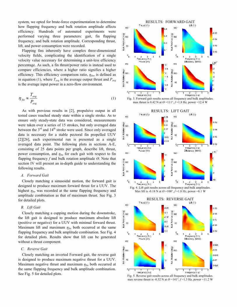
D. Passive Curvature Gait
Passive curvature utilizes fewer actuators so therefore has
reduced mechanical complexity and power consumption. But it
was previously unknown how passive curvature affects
propulsive efficiency. As shown in Fig. 6, the fin bulk rotation
motor was commanded to flap using forward gait kinematics
while the individual rib micro-servo actuators were left
unpowered. As with active curvature gaits, both maximum
forward thrust and maximum ŋfin occurred at the same flapping
frequency and bulk amplitude combination for the passively
flapping fin. Passively deforming thrust was nearly half that of
active curvature, yet ŋfin was almost double. These results
experimentally demonstrate that actively-controlled fin
curvature produces higher thrust than passive curvature, at the
cost of higher power consumption and propulsive efficiency.
However, this could be a function of how the specific fin
design passively flexes, and possibly not apply to other fins of
significant mechanical and kinematic deviation.
E. Rigid Fin Gait
Within the literature there is significant research on rigid fin
flapping. While a 1:1 comparison cannot be made as our fin
does not perform feathering motions, a rigid-fin test can
provide clues toward how the geometric shape of a
symmetrically flapping fin about a single axis affects thrust.
Our fin was commanded to remain rigid (zero curvature)
while the fin bulk rotation motor performed the forward gait.
Results are shown in Fig. 7. The rigid fin produced slightly
less thrust than the passive fin did, at a lower ŋfin, with slightly
higher power consumption. This power increase was due to the
energy the actuators needed to hold the ribs rigid.
IV. INTERPRETATION OF RESULTS
The fin test results all carry several important common
features. The colored surface plots of each tested gait are
bounded by three major regions (see Fig. 8). The left and
bottom sides compose the untested region, where early testing
[1] determined that very low flapping frequencies and small
bulk amplitudes result in ineffective output thrust. As such, no
further data in this region was obtained.
The two other regions, the tested and impossible regions as
labeled in Fig. 8, are bounded by a curved black line of high
significance which defines the limitations of the fin. Given the
governing physics of any pectoral fin, it is impossible for fin
motions to exceed beyond that curved boundary. This curve is
inherent to all flapping actuators, and can be defined as in
equation (2) where an increase in fin flapping frequency, f, or
bulk rotation amplitude, θ , will result in the decrease of the other.
max
1
θ∝f (2)
RESULTS: PASSIVE GAIT
Fig. 6. Passive gait results across all frequency and bulk amplitudes.
max thrust is 0.24 N at Ө =102°, f =2.2 Hz, power =5.8 W
RESULTS: RIGID GAIT
Fig. 7. Rigid gait results across all frequency and bulk amplitudes.
max thrust is 0.21 N at Ө =100°, f =2.2 Hz, power =7.2 W
Fig. 8. Guide to Pectoral Fin Brute-Force Testing Results:
Untested Region – poor fin performance
Impossible Region – fin is incapable of this bulk/freq. combo
Tested Region – region where results were obtained
between A and B – desired region for standard fin operation
IMPOSSIBLE
REGION
TESTED
REGION UNTESTED REGION
UNTESTED REGION
COP
(OPTIMAL)
A
B
GUIDE TO RESULTS

We define this curved boundary for pectoral fins as the
‘curve of optimal performance,’ and abbreviate it as COP, as
shown in Fig. 8. The COP is bounded by two factors. Any
amplitude-frequency combination to the left of dashed line A
results in poor output thrust. Any amplitude-frequency
combination to the right of dashed line B results in high
oscillatory force spikes with the potential to mechanically
damage the system.
For all three gaits, including passive curvature and rigid-fin
cases, we found the optimal point, Op, which quantitatively
defines the optimal fin flapping frequency and bulk rotation
amplitude for both maximum ŋfin and thrust, to always be
located on the COP. This holds great significance in that
finding the Op of any given pectoral fin does not require
intense testing. A few short experiments can be performed to
locate the COP, and a trend line can be fitted appropriately. By
analyzing the ŋfin trend on that curve, the Op can be quickly
approximated with relatively high accuracy. For all gaits
tested, commanding the fin to operate within the Impossible
Region will guarantee operation on the COP. While it may be
possible to intentionally design a gait where the COP does not
exist, there is no evidence to suggest such a gait would be
effective.
It should be noted that limited experiments by [29] have
come across similar results, where extrapolated data clearly
shows the inverse relationship between flapping frequency and
bulk rotation amplitude. However, their work did not realize
its significance with respect to efficiency.
V. ENERGY EXPENDITURES
To increase the efficiency of a flapping fin, it must first be
understood quantitatively where energy is used in the system.
The following sections consider the energy expenditures,
offering both experimental data and formulations for the
governing physics that define the COP. This analysis will only
cover that which defines the bulk rotation, and not the energy
spent to create fin surface curvature.
A. Rotational Inertia
Any rotating body with mass has rotational inertia. A
flapping actuator, which rotates about its root axis, has
rotational inertia partially defining its COP as it must reverse
its rotational direction twice during a full fin stroke. Both
velocity and energy is lost during each reversal. The flapping
fin can be analyzed as a kinetic energy KE problem [31],
where energy spent is that which is required to rotate the fin
mass about the rotational axis (Fig. 9).
KE is defined as in equation (3), where I is the moment of
inertia and ω is rotational velocity.
2
2
1ω⋅= IKE (3)
Fig. 9 a) Pectoral fin design, and its b) point mass representation.
To calculate I, the fin is simplified as a point mass mfin at
radius rfin from fin axis of rotation as in equation (4) and Fig.
9b. L is fin length, and rfin is approximated as in equation (5).
2
finfinrmI = (4)
Lrfin3
1= (5)
Fin rotational velocity ω can be defined as in equation (6).
f is fin flapping frequency, and θ is the maximum bulk rotation amplitude angle in radians.
fdt
d⋅== θ
θω (6)
Combining equations (3)-(6), we get equation (7)
representing the kinetic energy required to flap a pectoral fin.
Since the fin must be both accelerated and decelerated during
both the up and down strokes, KEfin has been multiplied by 4.
finfin mfLKE 222
9
2θ= (7)
Equation (7) only accounts for the rotational KE of the
deformable surface part of the fin, so KE for the rotation of the
base and actuators must also be accounted for. Using equations
(3), (4), (6), and Fig. 9b, we now get equation (8). ract is
defined as the distance from the fin axis of rotation to the
actuators center of mass, mact. As with equation (7), KEact has
been multiplied by 4.
2222 frmKE actactact θ= (8)
Total fin kinetic energy can be estimated by adding
equations (7) and (8). Plugging in typical representative values
for masses, lengths, and frequency, the pectoral fin system
requires a very insignificant total KE of only ~0.00085W.
mfin
mact
rfin
ract
L
Ө
a b
microservos
ribs
B. Fluidic Energy Losses
Fluidic loss is the kinetic energy lost to the fluid moving
about the pectoral fin. Fluidic losses are very difficult to
measure experimentally as all fins have inseparable
mechanical losses, too. As such, we took two approaches to
determining fluidic loss: computationally and experimentally.
The first approach was done using a 3D unsteady Navier
Stokes incompressible computational fluid dynamics solver
(CFD) [3][23][32]. The advantage of using CFD over robotic
experiments is that it can ignore all but fluidic losses – such as
mechanical inefficiencies. Fin kinematics, obtained directly
from experiments using our high speed camera system
[1][2][30], were modeled within CFD. Each gait was studied at
several representative fin flapping frequencies and bulk
rotation amplitudes. It was found in all cases, as shown in
Table I, that energy lost to the fluid represented less than 2%
of total experimentally measured energy consumption.
The second approach was to experimentally change the
medium in which the robotic fin flapped. The assumption was
that by drastically changing the fluid viscosity, a change in
power consumption can be identified representing fluidic
losses. The fin performed each gait at several representative
fin flapping frequencies and bulk rotation amplitudes in both
air and water, and measurements were taken. It was found that
not only were the in-air and in-water kinematics nearly
identical [1], but no measurable power consumption
differences could be identified.
As such, we conclude that fluidic losses are insignificant
compared to other energy losses of our pectoral fin system.
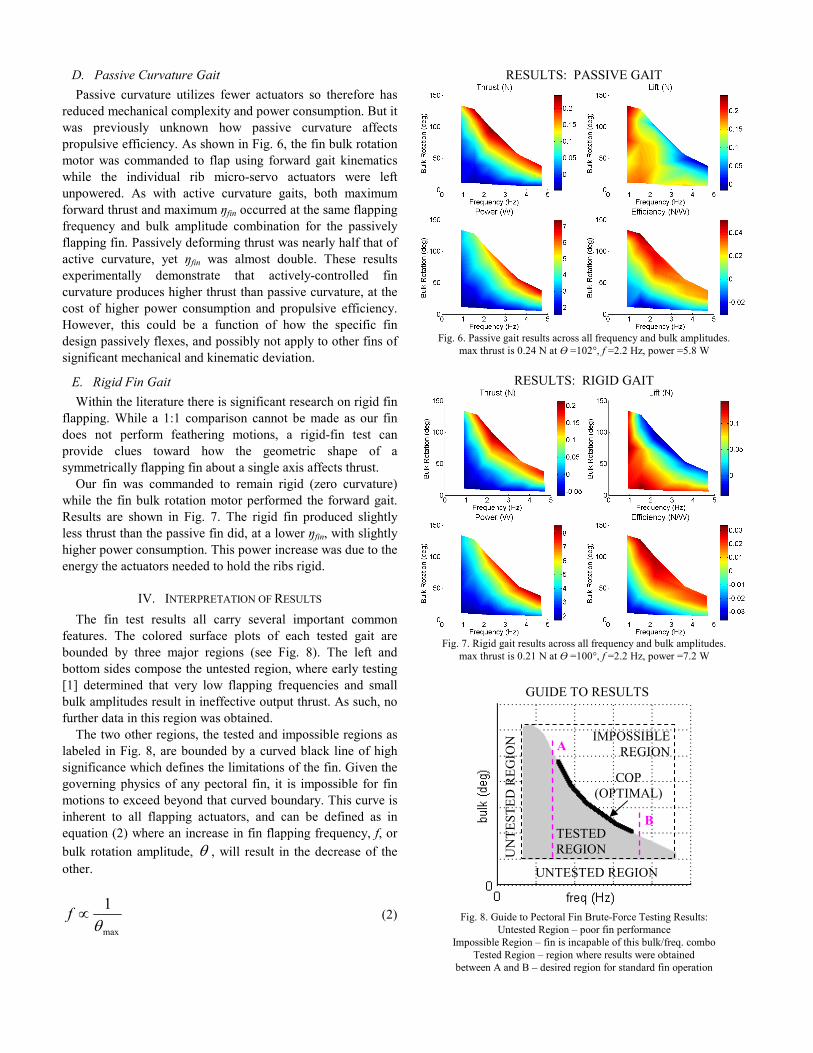
TABLE I
EXPERIMENTAL AND CFD COMPUTED POWER CONSUMPTION
Gait θ Freq. Exp. CFD
Forward 130.3 0.909 Hz 11.5 W 0.1322 W
Forward 64.6 2.208 Hz 14.9 W 0.1159 W
Lift 43.5 3.08 Hz 9.5 W 0.127 W
Reverse 48.3 3.0 Hz 9.5 W 0.168 W
Reverse 125.5 1.0 Hz 11.2 W 0.0987 W
A comparison of mean power consumption computed in CFD and
measured experimentally for multiple flapping fin gaits. CFD only measures
fluidic energy loses, while experimental measurements account for all losses
including inefficiencies. Fluidic energy loss can be considered negligible.
C. Actuator Loss and Inefficiency
Because combined kinetic and fluidic energy requirements
for fin flapping are an insignificant part of total energy
requirements, the only other major energy loss is within the
actuators themselves.
To test the energy lost within the actuators, each servo was
commanded to perform the required kinematic motions while
unconnected to any mechanical systems, i.e. the servos were
physically separated from the fin. As no real work was
performed, the measured energy drain would approximately
represent only the energy wasted within the servo. Much of
this energy is lost as heat by the driver circuitry, electro-
mechanics of the coils, and gear box efficiency losses. It was
experimentally determined that no less than ~89% of all
energy was lost in this manner. The remaining spent energy is
believed to be used for creating fin curvature, of which is out
of scope for this paper.
Therefore, in terms of mechanical design, the single most
effective means to improve pectoral fin efficiency is to select
actuators with higher efficiencies.
VI. DISCUSSION
The following discussion sections will cover limitations of
our experiments, propose implications of our results, discuss
further possible research, and declare our current research
direction.
A. On Fluidic Flow
Our experimental tests were of a fin being actuated without
an externally applied flow. CFD was therefore used to confirm
that thrust and lift forces remained valid under an external flow
scenario [2].
B. Does Thrust Increase With Frequency and Amplitude?
Fig. 10 shows frequency compared to output thrust over
multiple bulk rotation amplitudes for the forward gait. It shows
a general trend that for any given bulk rotation amplitude, as
frequency increases, so does output thrust. This is in
agreement with previous literature [1][3]-[8].
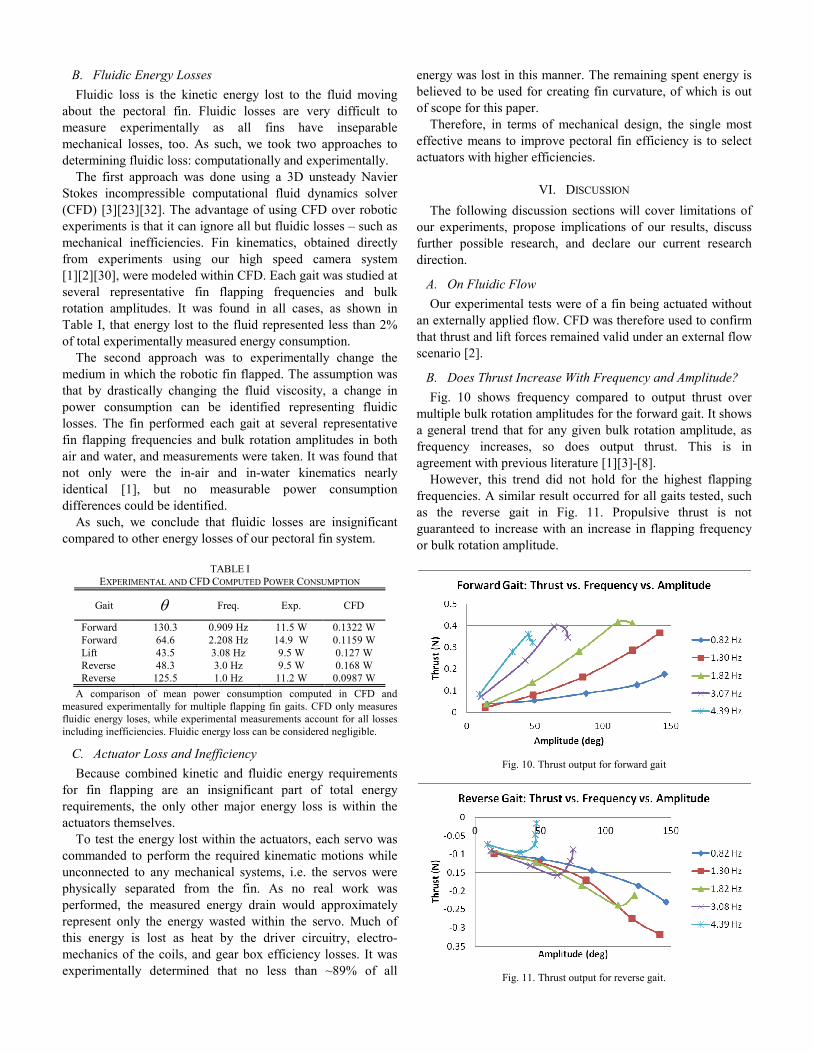
However, this trend did not hold for the highest flapping
frequencies. A similar result occurred for all gaits tested, such
as the reverse gait in Fig. 11. Propulsive thrust is not
guaranteed to increase with an increase in flapping frequency
or bulk rotation amplitude.
Fig. 10. Thrust output for forward gait
Fig. 11. Thrust output for reverse gait.

C. On Scaling
Although this study did not investigate scaling, the results
offer strong clues as to how scaling fin size affects fin
efficiency. Given that fluidic and kinematic energy losses were
shown to be insignificant, this leaves the scaling of fin
efficiency to be solely dominated by the scaling laws of its
actuator mechanisms – in this case, DC servos. No literature
could be identified which determines power and thrust scaling
properties for servomotors.
Nature also offers clues. For biological muscle-based
pectoral fins, it has been found that smaller fish have a higher
fin flapping frequency [6][33], equivalently smaller fish have a
higher ‘physiological limit’ for flapping frequency [6], and that
energy consumption likely scales linearly with biological
pectoral fin size [33].
Being a multi-variable problem, deeper research must be
done to determine which features dominate efficiency and by
how much during fin scaling.
D. The Strouhal Number
The Strouhal number is a dimensionless value often used for
describing and predicting the performance of flapping fin
designs under varying parameters, with the expectation that
difficult to model characteristics would be accounted for. It is
defined as in equation (9), where R is the characteristic fin
length, f is the fin flapping frequency, and V is defined as the
input fluid velocity.
V
fRSt
⋅= (9)
However, the Strouhal number is overly simplified on many
accounts. V is poorly defined, as the input fluid velocity across
a pectoral fin can be significantly smaller than the output fluid
velocity [1], and is neither constant nor evenly distributed
across the fin [22]. V is also wrongly assumed to be a single
uni-directional vector when in actuality it is a spinning vortex
[1][13][14][17][18]. Given these issues, such as for a hovering
fin where input flow is minimal and/or unknown, V is often
then redefined as the fin tip rotational velocity, Vtip.
The length R does not factor in fin shape or surface area,
and does not account for fin aspect ratio (AR) – a value well
known for influencing fin thrust [1][3][4][12][34]. And though
the Strouhal number scales linearly with fin length, there is
evidence that suggests fin thrust production scales
quadratically with fin length [35].
The fin flapping frequency, f, and the flapping amplitude,
θ , do not account for non-symmetric flapping, such as when the upstroke and downstroke have differing completion times.
Additionally, the Strouhal number entirely ignores fin surface
curvature modulation and its creation of unique kinematics-
dependent wake interactions.
Despite a fixed R, f, θ , and V, any thrust vector can be produced by modifying fin surface curvature alone [2]. The
Strouhal number also accounts for only positive thrust, yet the
lift gait results in Fig. 4 show that just varying θ or f alone can create both positive and negative thrust. This is consistent with
preliminary evidence found in [36] and [37], demonstrating
that surface curvature modulation alone can have a significant
impact on output thrust. Any fin comparisons made with the
Strouhal number must be made while holding fin kinematics
constant, therefore a separate Strouhal for each fin gait would
be required. Comparing similar fins using the Strouhal number
cannot be performed using dissimilar kinematics.
As such, the Strouhal number is an ineffective method of
predicting pectoral fin performance for all but the most
simplified scenarios.
E. On Experimental Automation
Automation of experiments played a key part in this
research. The test fin, when including all preliminary
experiments, tested 7000+ different gait-frequency-amplitude
combinations through 5000+ individual experiments and 90k+
fin flap cycles.
In software, embedded for-loops were used to step through
each designed kinematics combination, and then automatically
reset all hardware back into starting locations after each
experiment. MatLAB and Excel scripts would then process the
massive data-dumps into useful summary graphs and tables.
There is one important disadvantage to experimental
automation that must be mentioned. Automation is beneficial
in that it allows for a greater number of tests to be performed.
However, that increase in mechanical cycles resulted in more
frequent hardware failures. Materials fatigued and failed,
servos designed to work only a limited number of hours
burned out, screws slowly came loose, and sensor calibrations
shifted. Continual visual inspection of data and hardware was
required to identify failures. An automatic failure detection
system based on sensor data was not implemented, but is
technically feasible given a well understood system.
F. An Explanation for the Biological Refractory Period
In pectoral fin flapping of biological fish, within the flap
cycle, exists a yet unexplained ‘refractory period’ [6][38]-[41].
Between each flap, the pectoral fin pauses for a small period of
time. This study offers a possible explanation as to why fish
pectoral fins have a refractory period.
As per the results of this study, if a fish desired to travel at
maximum speed, it must flap its fins at the maximum
physiological rate. This would simultaneously allow for both
maximum thrust and maximum propulsive efficiency. But
suppose the fish desired to only travel at reduced speed –
should it reduce flapping frequency, reduce flapping
amplitude, or keep both frequency and amplitude at maximum
but add a pause between each flap?
In electro-magnetics, varying the input voltage to a DC
motor can vary its rotational speed; however, motors operate at
its highest efficiency at only a specific voltage. By controlling
the pulse-width of an input square wave at this set voltage, DC
motors can then continually operate at maximum efficiency yet
still vary speed. This speed control technique is referred to as
pulse width modulation, or PWM.
We propose that the refractory period is a biological version
of PWM, that it is the means to modulate speed while still
retaining maximum pectoral fin efficiency. As large bodies are
relatively insensitive to minute oscillating fin forces, a small
refractory period would not noticeably oscillate speed or
degrade stability [2][26].
As evidenced by the literature, fish velocity has been shown
to increase as the refractory period decreases [8]. However, the
work by [39] has shown a refractory period only at the highest
velocities – evidence that possibly other factors also influence
the refractory period. It was suggested by [39] that this
difference may contribute to the ability of the surf perch [8] to
use pectoral fin locomotion over a larger range of speeds than
can the bluegill.
G. Do Fish Pectoral Fins Have a COP?
The literature shows that the cost of transport (COT) of fish
pectoral fin propulsion decreases as fish velocity increases
[10][42][43], suggesting that pectoral fin propulsive efficiency
increases as propulsive thrust increases. This is in agreement
with the COP results in this paper.
A COP would also suggest a physical mechanical limitation
in pectoral fin propulsion, preventing yet higher thrust. While
a well known fact that fish swap from pectoral fin to caudal
tail propulsion at higher speeds [6][33][38][39][44][45][46], it
was not clear why. Pectoral fin propulsion has a lower cost of
transport (COT) and O2 consumption than caudal tail
propulsion for many fish species [10][42][44], so this swap is
likely not for energetic purposes. Previous literature [9][10]
suggested mechanical limitations of pectoral propulsion
prevents higher velocities, perhaps due to muscle contraction
speed, muscle size, strength of materials, etc. Perhaps only
caudal tail propulsion, despite being less efficient, is
physiologically capable of operating at these higher velocities.
VII. CONCLUSION
The effects of fin flapping frequency and bulk rotation
amplitude of a pectoral fin were studied both experimentally
and computationally. A simple relationship was discovered
that maximum thrust and maximum propulsive efficiency can
both simultaneously occur given a specific set of fin control
parameters. This happens when the actuators reach their
physical limitations, where fin flapping frequency and bulk
rotation amplitude become inversely related. Fin propulsive
efficiency was determined to be dominated significantly by
actuator selection. The active curvature fin produced nearly
double the thrust of the passive curvature fin, at the cost of
higher power consumption and half the propulsive efficiency.
The Strouhal number was shown to be ineffective for
describing pectoral fin propulsion.
ACKNOWLEDGMENTS
Thanks to the many forum members at societyofrobots.com
for their continuous technical support and advice.
REFERENCES
[1] J. S. Palmisano, R. Ramamurti, K.J. Lu, J. Cohen, W. C. Sandberg, and
B. Ratna, “Design of a Biomimetic Controlled-Curvature Robotic
Pectoral Fin,” IEEE International Conference on Robotics and
Automation (ICRA), Rome, Italy, 2007.
[2] J. S. Palmisano, J. Geder, R. Ramamurti, W. C. Sandberg, and B. Ratna,
“Robotic Pectoral Fin Thrust Vectoring Using Weighted Gait
Combinations,” Applied Bionics and Biomechanics, vol. 9, pp. 333-
345, 2012.
[3] R. Ramamurti and W. C. Sandberg, “Computational Fluid Dynamics
Study for Optimization of a Fin Design,” 24th AIAA Applied
Aerodynamics Conference, San Francisco, California, 2006, AIAA-
2006-3658.
[4] J. Walker and M. Westneat, “Performance limits of labriform propulsion
and correlates with fin shape and motion,” The Journal of Experimental
Biology, vol. 205, pp. 177-187, 2002.
[5] J. Walker, “Functional Morphology and Virtual Models: Physical
Constraints on the Design of Oscillating Wings, Fins, Legs, and Feet at
Intermediate Reynolds Numbers,” Integrative and Comparative
Biology, vol. 42, pp. 232-242, 2002.
[6] M. Mussi, A. Summers, and P. Domenici, “Gait Transition Speed,
Pectoral Fin-beat Frequency, and Amplitude in Cymatogaster
Aggregata, Embiotica Lateralis, and Damalichthys Vacca,” Journal of
Fish Biology, vol. 61, no. 5, pp. 1282-1293, 2002.
[7] J. Walker and M. A. Westneat, “Labriform propulsion in fishes:
kinematics of flapping aquatic flight in the bird wrasse, Gomphosus
varius,” Journal of Experimental Biology, vol. 200, pp. 1549-1569,
1997.
[8] P. Webb, “Kinematics of Pectoral Fin Propulsion in Cymatogaster
Aggregata,” Journal of Experimental Biology, vol. 59, pp. 697-710,
1973.
[9] M. E. Hale, R. D. Day, D. H. Thorsen, and M. W. Westneat, “Pectoral
fin coordination and gait transitions in steadily swimming juvenile reef
fishes,” The Journal of Experimental Biology, vol. 209, pp. 3708-3718.
[10] K. Korsmeyer, J. Steffensen, and J. Herskin, “Energetics of median and
paired fin swimming, body and caudal fin swimming, and gait transition
in parrotfish (Scarus schlegeli) and triggerfish (Rhinecanthus
aculeatus),” The Journal of Experimental Biology, vol. 205, pp. 1253-
1263, 2002.
[11] R. Ramamurti and W. C. Sandberg, “The influence of fin rigidity and
gusts on force production in fishes and insects: a computational study,”
42nd AIAA Aerospace Sciences Meeting, Reno, Nevada, 2004, AIAA
2004-404.
[12] S. Combes and T. Daniel, “Shape, Flapping and Flexion: Wing and Fin
Design for Forward Flight,” The Journal of Experimental Biology, vol.
204, pp. 2073-2085, 2001.
[13] G. Lauder and P. Madden, “Learning from Fish: Kinematics and
Experimental Hydrodynamics for Roboticists,” International Journal of
Automation and Computing, vol. 4, pp. 325-335, 2006.
[14] M. Bozkurttas, R. Mittal, H. Dong, G. Lauder, and P. Madden, “Low-
dimensional models and performance scaling of a highly deformable
fish pectoral fin,” Journal of Fluid Mechanics, vol. 631, pp. 311-342,
2009.
[15] J. Gottlieb, “The Development of a Multi-Functional Bio-Robotic
Pectoral Fin,” M.S. thesis, Dept. Mech. Eng., Drexel University,
Philadelphia, PA, 2009.
[16] J. Walker and M. Westneat, “Mechanical performance of aquatic rowing
and flying,” Proceedings: Biological Sciences, vol. 267, no. 1455, pp.
1875-1881, 2000.
[17] E. Drucker and G. Lauder, “Locomotor Forces on a Swimming Fish:
Three-Dimensional Vortex Wake Dynamics Quantified Using Digital
Particle Image Velocimetry,” Journal of Experimental Biology, vol.
202, pp. 2393-2412, 1999.
[18] G. Lauder and E. Drucker, “Forces, Fishes, and Fluids: Hydrodynamic
Mechanisms of Aquatic Locomotion,” Physiology, vol. 17, no. 6, pp.
235-240, 2002.
[19] J. S. Palmisano, J. Geder, M. Pruessner, and R. Ramamurti, “Power and
Thrust Comparison of Bio-mimetic Pectoral Fins with Traditional
Propeller-based Thrusters,” 18th International Symposium on
Unmanned Untethered Submersible Technology (UUST), Portsmouth,
NH, USA, 2013.

[20] D. Thorsen and M. Westneat, “Diversity of Pectoral Fin Structure and
Function in Fishes With Labriform Propulsion,” Journal of
Morphology, vol. 263, pp. 133-150, 2005.
[21] B.P. Trease, K.J. Lu, and S. Kota, “Biomimetic Compliant System for
Smart Actuator-Driven Aquatic Propulsion: Preliminary Results,”
ASME International Mechanical Engineering Congress & Exposition,
Washington, D.C., 2003, IMECE2003-41446.
[22] R. Ramamurti, W. C. Sandberg, R. Löhner, J. Walker, and M. Westneat,
“Fluid dynamics of flapping aquatic flight in the bird wrasse: three-
dimensional unsteady computations with fin deformation,” Journal of
Experimental Biology, vol. 205, pp. 2997-3008, 2002.
[23] R. Ramamurti, R. Löhner, and W. C. Sandberg, “Computation of the 3-
D Unsteady Flow Past Deforming Geometries,” International Journal of
Computational Fluid Dynamics, vol. 13, issue 1, pp. 83-99, 1999.
[24] R. Ramamurti, J. Geder, J. S. Palmisano, B. Ratna, and W. C. Sandberg,
“Computations of Flapping Fin Propulsion for UUV Design,” 47th AIAA
Aerospace Sciences Conference, Orlando, FL, 2009, AIAA-2009-0724.
[25] R. Ramamurti, J. Geder, J. S. Palmisano, B. Ratna, and W. C. Sandberg,
“Computations of Flapping Flow Propulsion for Unmanned Underwater
Vehicle Design,” AIAA Journal, vol. 48, no. 1, pp. 188-201, January
2010.
[26] J. Geder, J. S. Palmisano, R. Ramamurti, W. C. Sandberg, and B. Ratna,
“A New Hybrid Approach to Dynamic Modeling and Control Design for
a Pectoral Fin Propelled UUV,” 15th International Symposium on
Unmanned Untethered Submersible Technology (UUST), Durham, NH,
USA, 2007.
[27] J. Geder, J. S. Palmisano, R. Ramamurti, W. C. Sandberg, and B. Ratna,
“Fuzzy Logic PID Based Control Design and Performance for Pectoral
Fin Propelled Unmanned Underwater Vehicle,” International
Conference on Control, Automation, and Systems, Seoul, Korea, 2008.
[28] J. Geder, R. Ramamurti, J. S. Palmisano, M. Pruessner, B. Ratna, and
W. C. Sandberg, “Sensor Data Fusion and Submerged Test Results of a
Pectoral Fin Propelled UUV,” International Symposium on Unmanned
Untethered Submersible Technology (UUST), Durham, NH, USA,
2009.
[29] S. Licht, V. Polidoro, M. Flores, F. Hover, and M. Triantafyllou,
“Design and Projected Performance of a Flapping Foil AUV,” IEEE
Journal of Oceanic Engineering, vol. 29, no. 3, pp. 786-794, 2004.
[30] J. Geder, W. C. Sandberg, and R. Ramamurti, “Multi-Camera, High-
Speed Imaging System for Kinematics Data Collection,” Naval
Research Laboratory Memorandum Report NRL/MR 6401-07-9054,
September, 2007.
[31] R. Blake, “The Mechanics of Labriform Locomotion, I. Labriform
Locomotion in the Angelfish (Pterophyllum Eimekei): An Analysis of
the Power Stroke,” Journal of Experimental Biology, vol. 82, pp. 255-
271, 1978.
[32] W. C. Sandberg and R. Ramamurti, “Unsteady Flow Computational
Technology for Flapping Fins,” Proc. Unmanned Undersea
Submersibles Technology Symposium, Durham, NH, 1999, pp. 182-194.
[33] E. Drucker and J. Jensen, “Pectoral Fin Locomotion in the Striped
Surfperch II. Scaling Swimming Kinematics and Performance at a Gait
Transition,” Journal of Experimental Biology, vol. 199, pp. 2243-2252,
1996.
[34] P. Wainwright, D. Bellwood, and M. Westneat, “Ecomorphology of
Locomotion in Labrid Fishes,” Environmental Biology of Fishes, vol.
65, pp. 47-62, 2002.
[35] J. Geder, R. Ramamurti, J. S. Palmisano, M. Pruessner, B. Ratna, and
W. C. Sandberg, “Scaling Studies for an Actively Controlled Curvature
Robotic Pectoral Fin,” International Conference on Intelligent Robotics
and Applications (ICIRA), Montreal, Canada, 2012.
[36] J. Tangorra, S. N. Davidson, I. Hunter, P. Madden, G. Lauder, H. Dong,
M. Bozkurttas, and R. Mittal, “The Development of a Biologically
Inspired Propulsor for Unmanned Underwater Vehicles,” IEEE Journal
of Oceanic Engineering, vol. 32, no. 3, July, 2007.
[37] J. Tangorra, G. Lauder, P. Madden, R. Mittal, M. Bozkurttas, and I.
Hunter, “A Biorobotic Flapping Fin for Propulsion and Maneuvering,”
IEEE International Conference on Robotics and Automation (ICRA),
Pasadena, CA, 2008.
[38] E. Drucker and J. Jensen, “Pectoral fin locomotion in the striped
surfperch. I. Kinematic effects of swimming speed and body size,” The
Journal of Experimental Biology, vol. 199, no. 10, pp. 2235-2242,
1996.
[39] A. C. Gibb, B. C. Jayne, and G. V. Lauder, “Kinematics of pectoral fin
locomotion in the bluegill sunfish Lepomis macrochirus,” Journal of
Experimental Biology, vol. 189, pp. 133-161, 1994.
[40] S. D. Archer and I. A. Johnston, “Kinematics of labriform and
subcarangiform swimming in the Antarctic fish Notothenia neglecta,”
Journal of Experimental Biology, vol. 143, pp. 195-210, 1989.
[41] E. Drucker and J. Jensen, “Kinematic and electromyographic analysis of
steady pectoral fin swimming in the surfperches,” Journal of
Experimental Biology, vol. 200, no. 12, pp. 1709-1723, 1997.
[42] J. L. Kendall, K. S. Lucey, E. A. Jones, J. Wang, and D. J. Ellerby,
“Mechanical and energetic factors underlying gait transitions in bluegill
sunfish (Lepomis macrochirus),” Journal of Experimental Biology, vol.
210, pp. 4265-4271, 2007.
[43] M. S. Gordon, J. R. Hove, P. W. Webb, and D. Weihs, “Boxfishes as
unusually well controlled autonomous underwater vehicles,”
Physiological and Biochemical Zoology, vol. 73, no. 6, pp. 663-671,
2000.
[44] M. Cannas, J. Schaefer, P. Domenici, and J. F. Steffensen, “Gait
transition and oxygen consumption in swimming striped surfperch
Embiotoca lateralis Agassiz,” Journal of Fish Biology, vol. 69, no. 6,
pp. 1612-1625, 2006.
[45] I. C. Stobutzki and D. R. Bellwood, “An analysis of the sustained
swimming abilities of pre- and post-settlement coral reef fishes,”
Journal of Experimental Marine Biology and Ecology, vol. 175, pp.
275-286, 1994.
[46] F. G. Whoriskey and R. J. Wootton, “The swimming endurance of
threespine sticklebacks, Gasterosteus aculeatus L., from the Afon
Rheidol, Wales,” Journal of Fish Biology, vol. 30, no. 3, pp. 335-339,
1987.