B-Reliable: Asset Reliability as a Business Strategy to Increase Competitiveness

1
HOW TO INCREASE RELIABILITY AND PREVENT THREADED ASSEMBLY FAILURE

LOCTITE® is the registered trademark of Henkel IP & Holding GmbH. All other marks are the trademarks and service marks of their respective owners. No part of this book may be reproduced without prior permission of Henkel. ©2020 Henkel Corporation. All rights reserved.
HOW TO INCREASE RELIABILITY AND PREVENT THREADED ASSEMBLY FAILURE2

3
1 Foreword 4
2 Introduction 6
3 Definitionofanadhesive 10
4 Historyofadhesivesandthreadlockers 12
5 Thebasicsofadhesives 165.1 Thebasicsofbonding 175.2 Adhesion 175.3 Cohesion 175.4 Understandingthebondingprocess 185.4.1 Overview of the bonding process 185.4.2 Surface preparation 185.4.2.1 Cleaning 205.4.3 Application of product 235.4.4 The curing process 245.4.5 Performance and testing of cured adhesive 265.4.5.1 Cured adhesive strength 275.4.5.2 Effect of environment on cured bondline 27
6 Threadedassemblies 286.1 Threadedfastenermechanics 296.1.1 Inclined plane 316.2 Gettingtherightclampload 346.3 Controllingclampload 356.3.1 Determining the k-factor 386.3.2 Mathematics of bolt tightening 386.3.3 Influencingfactorsinachieving correct clamp load 436.4 Fastenerfailures 486.4.1 Common myths about threaded fasteners 486.4.2 Why threaded assemblies fail 486.4.3 Traditional mechanical methods
to prevent failure 566.4.3.1 Preventing relaxation 586.4.3.2 Preventing self-loosening 586.5 Threadlockers 636.5.1 The LOCTITE® Threadlocker solution 636.5.2 Anaerobic cure mechanism 676.5.3 Factorsinfluencinganaerobiccuring 686.5.3.1 Substrates 696.5.3.2 Temperature 726.5.3.3 Gap between substrates 726.5.4 Surface preparation for threadlockers 736.5.4.1 Chemical preparation - activators 75
6.6 Applyingtheproduct 766.6.1 Properties of threadlockers 786.6.1.1 Uncured threadlocker properties 786.6.1.2 Cured threadlocker properties 796.6.2 Assembly validation 846.7 Validationofassemblies 88
7 Dispensing 907.1 Whydispensingequipment? 917.2 Dispensingtechnology 927.2.1 Pressure/time dispensing 927.2.2 Volumetric dispensing 947.2.2.1 Peristaltic pump 947.2.2.2 Progressive cavity pump 957.3 Manualdispensing 977.3.1 Manual hand pumps 977.3.2 Benchtop digital peristaltic dispenser 977.3.3 Controller/reservoir with valve 987.4 Automateddispensing 997.4.1 Automated time/pressure system 1007.4.2 Automated volumetric system 1027.5 Equipmentselection 102
8 Troubleshooting 1048.1 Failuremodeanalysis 1058.2 Rootcauses 107
9 Shelflife 108
10 Certificationsandstandards 11010.1 Productcertifyingorganizations 11110.2 Teststandards 111
11 Appendix 11211.1 Contact 11311.2 Chemicalcompatibilitychart 11311.3 Unitconversiontable(imperial/metric) 12311.4 Volumecalculation 12411.5 Technicalinformation:Standard
testmethodsforthreadlockertesting 12411.5.1 ISO 10964 adhesives 12411.5.2 ISO 10123 adhesives 12511.5.3 ISO 16047 assembly 126
12 Bibliography 128
CONTENTS

FOREWORDSection 1
Combined expertise. Exponentialimpact.
4 HOW TO INCREASE RELIABILITY AND PREVENT THREADED ASSEMBLY FAILURE
I n 1876, Fritz Henkel’s love for science led him to recognize the need for a universal detergent based on silicate. From that day forward, Henkel’s focus on solving customer challenges has helped us build a vast body of
expertise as a global manufacturer of adhesives, laundry products and beauty care products. LOCTITE®,oneofHenkel’sflagshipbrands,reflectsanddrivesmuch of that expertise. As the global leader in adhesives and sealants, our footprint in over 120 countries and our passion for solutions that help unlock the limitless potential of man and machine allow us to provide you, our customer, the local support you need to solve your maintenance and design challenges. Our global leadership position in the adhesives market could not have been achieved without the expertise, dedication and knowledge of LOCTITE® and our technical teams across the globe.
It also could not have been achieved without you, our customers. By inviting us into your challenges and embracing our solutions, you have helped us help you. Through our work for you, we have developed market-, industry- and technology-specificexpertisethatweputbacktoworkforyou.Manycustomershave commented on the expertise of the LOCTITE® teams they interact with. The compliment is well-earned, as our people include many patent holders and membersofcertificationbodies.Theyaresomeofthefinestmindsinindustry.
Now, just as you have enabled us to build our expertise, we want to empower you. While the expertise of our technical teams is a source of great pride to us, our greater goal is to help you solve your technical challenges by providing insight into adhesive technologies. This module, and our larger collection on our adhesive technologies and applications, is part of that effort.
We are proud to share our expertise with you—the expertise you have helped us build—in this module and, of course, in our face-to-face interactions. We hope the learning we’ve assembled here will help you make your machines more powerful, durableandefficient,andwelookforwardtohelpingyousolveyourchallenges in the near future!
With pride and gratitude,
Dr.NigelFayHenkel Corporate Director Product Development, Engineering & Technical Service
Dr.KouroshBahramiHenkel Corporate Vice President
Forcountryorregion-specificlistingsoftechnicalcontactnumbers,
please see appendix on page 113.
5
Combined expertise. Exponential impact.

INTRODUCTIONSection 2
hank you for taking an interest in understanding threaded fasteners and threadlocking applications. Our goal with this book is to help you makeinformeddecisionsthatimprovetheefficacyofboltedjoints
within assemblies and keep plant operations running smoothly and efficiently.Bymakingourtechnicalandscientificknowledgeavailable, we hope to help you overcome design challenges, reduce scrap and increase the reliability of bolted joints. Ultimately, our hope is that you will use this expertise to overcome a wide range of engineering and maintenance challenges.
Thecontentyou’llfindhereexploresadhesivesandthedevelopmentof threadlockers, including how they work, then examines all kinds of industrial threaded assemblies, what makes them work and why they fail. Finally, it provides detailed information on threadlocker usage and application to help guarantee the best results.
This book is the culmination of our 65+ years as the original manufacturer of chemical threadlockers. As we have developed and manufactured chemical technology and built expert engineering and product development teams, we have learned how to help shape advancements in manufacturing and mainte-nance processes. Many of our team members were involved in the development of this book, and it would not have been possible without their contributions. A look at their backgrounds will make it clear why.
T
6 HOW TO INCREASE RELIABILITY AND PREVENT THREADED ASSEMBLY FAILURE

MichaelFeeney Senior Application Engineer 11 years at Henkel CurrentLocation:Toronto, CanadaProductTechnologyExpertise:Machinery adhesives, Structural adhesives As an application engineer, Michael has had a focus on threadlocking technology throughout his career, supporting manufacturing and maintenance operations in the US and Canada. His extensive engagement with customers and their applications has made him a leading expert in North America on threadlocking and machinery adhesive applications. Michael holds a degree in Mechanical Engineering from the University of Ottawa.
RudolfNeumayerSales Excellence and Training Technical Lead 32 years at Henkel CurrentLocation:Munich, GermanyProductTechnologyExpertise:Anaerobic machinery adhesives, Cyanoacrylates, Structural adhesives Over Rudolf’s 32 years with Henkel, he has become one of our leading technical experts in Europe, supporting both manufacturing and maintenance operations. He has helped troubleshoot and specify threadlocking applications across a broad range of industries, such as heavy duty equipment, powered drive systems, automotive powertrains and general industrial manufacturing. Rudolf holds an engineering degree in plastics technology. Dr.DavidCondron Product Development Technical Lead—Machinery Adhesives 16 years at Henkel CurrentLocation:Dublin, Ireland ProductTechnologyExpertise:Anaerobic adhesives, Cyanoacrylates David has a background in organometallic chemistry with a Ph.D. from University College Dublin. He has been involved in several product development roles in the chemical industry and has worked in the development of acrylate-based adhe-sives for the past 16 years. David currently leads a team involved in the develop-ment of new anaerobic products for various applications, such as threadlocking, thread-sealing,retainingandflangesealing.Akeyfocusofhisresearchefforts is the development of new sustainable high performance threadlockers designed to cure on many types of metal substrate.
7

ChulsooWoo TechnicalTrainingManager,AsiaPacific 34 years at Henkel
CurrentLocation:Shanghai, ChinaProductTechnologyExpertise:Anaerobic adhesives, Structural adhesives, Light cure adhesives Chulsoo started his career with LOCTITE®in1987asthefirsttechnicalserviceengineerinSouthKorea.HehasassistedwiththequalificationandspecificationofLOCTITE® Thread-lockers in numerous applications, including automotive drive trains, heavy duty machinery, railway, electric motors, loudspeakers and elevators, to name a few. Chulsoo continues to take pride in helping customers increase the reliability and performance of their assem-blies in manufacturing and maintenance while helping to reduce costs. ‘Anaerobics have been, and will continue to be in my DNA’.
Dr.ShabbirAttarwala ScientificFellow 33 years at Henkel
CurrentLocation:Rocky Hill, USAProductTechnologyExpertise:Anaerobic adhesives, Cyanoacrylate adhesives, Structural adhesives
Shabbir received a Ph.D. in Organic Chemistry from Polytechnic New York University, holds over 100 patents and has published dozens of technical papers and presentations.
Asaleadingexpertinhisfield,hehasmentoredandtrainedanumberofscientistsintheHenkel community and has played a key role in establishing research and development teamsinNorthAmerica,AsiaPacific,India,theMiddleEast,AfricaandTurkey.
8 HOW TO INCREASE RELIABILITY AND PREVENT THREADED ASSEMBLY FAILURE
Section2: Introduction

Anne Brown Technical Director
Rocky Hill, USA
BobOrme Senior Technology Specialist
Hemel Hempstead, UK
ChetanHire,Ph.D Senior Development Chemist
Rocky Hill, USA
DavidGettelsonEquipment Engineer, Technical Customer Services
Hemel Hempstead, UK
LauraLamard Global Marketing Customer Activation Manager
Bordeaux, France
OliverDroste Senior Application Engineer
Munich, Germany
SandraSabella Lab Operations Engineer
Rocky Hill, USA
SteveRayner Global Innovation Project Manager
Dublin, Ireland
Additional contributors
9

DEFINITION OF AN ADHESIVE
Section 3
From traditional to unexpected.
10 HOW TO INCREASE RELIABILITY AND PREVENT THREADED ASSEMBLY FAILURE
hesimplestdefinitionofanadhesiveisanymaterialusedtojoin components together. As technology has advanced, adhesives have been used in increasingly innovative ways that take on new challenges
and replace traditional methods. To ensure an adhesive will meet the require-ments of an application, it is important to understand those requirements fully.
ThedefinitionofanadhesiveaccordingtoEuropeanstandardsis:
EN923:2015‘non-metallic substance capable of joining materials by surface bonding (adhesion), and the bond possessing adequate internal strength (cohesion)’1
FromaHenkeltechnicalpointofview,anadhesiveisdefinedasacompoundapplied to a surface in a liquid, paste or deformable state to adapt the joint geometry on one or both surfaces, which hardens or cures to achieve adhesion and cohesion.
Many things we would not traditionally consider adhesives fall into this category. Threadlockersfulfilbothofthesedefinitions;theyconnectjoinedpartsthroughadhesion and exhibit cohesive strength. They are applied in a liquid state and cure between the joint geometry to achieve adhesion and cohesion.
Whenweunderstandthesedefinitions,itbecomesclearthatmanyaspectsofour lives are touched by adhesives.
T
11
From traditional to unexpected.
1. European Committee for Standardization, “Adhesives - Terms and Definitions.”

HISTORY OF ADHESIVES AND THREADLOCKERS
Section 4
A rich history and a bright future.
12 HOW TO INCREASE RELIABILITY AND PREVENT THREADED ASSEMBLY FAILURE

he science has changed but humans have been toolmakers and adhesive makers since the earliest days of human development. Stone tools from the Paleolithic era, 40,000–75,000 years ago, were bonded
to wood, antler and bone with organic resins such as pitch and bitumen. One of the best preserved examples we have of adhesive use in tools is the Ötzi Axe2 pictured in Figure 1.
ThroughouttheIndustrialRevolution,thefocusofmanufacturingwasvolume: how many assemblies could be manufactured in the shortest time. Today’s manufacturing and assembly industries also search for methods that allow for faster production while increasing the reliability of their products. Adhesives haveandwillcontinuetoplayaroleinincreasingefficiencyandreliability.
In 1945, two GE chemists, Birger Norlander and Robert Burnett, discovered a materialwhichtheycalled‘anaerobicpermafil’.Theyfoundthatwhentheysyn-thesized tetraethylene glycol dimethacrylate, heated it to between 65°C and 75°C (150°F–170°F), and bubbled air through it, an oxygenation reaction took place. When the liquid cooled, it would remain liquid for months, as long as aeration was continued as a bubbling air stream through the liquid at room temperature. When the air was turned off, the material would set up to a solid, highly crosslinked resin within minutes.2
In 1953, a stable formula and a practical application for Norlander and Burnett’s discovery was developed. American professor Vernon K. Krieble developed an anaerobic threadlocking adhesive in his basement laboratory at Trinity College in Hartford, Connecticut.
Krieble’s company, American Sealants, founded the LOCTITE® brand, a name chosen by Krieble’s daughter-in-law, Nancy Brayton Krieble, and registered as the officialtrademarkin1956.3
T
FIGURE 1A reconstruction of Ötzi’s axe, which used pitch as an adhesive, 3400–3100 BCE.
13
A rich history and a bright future.
2. Degano, Hafting of Middle Paleolithic Tools.
3. Grant, Drop By Drop, 17, 19, 21.

SealantmadeitsofficialpublicdebutatapressconferenceattheUniversityClubof New York on July 26 of that year, and a new era of mechanical reliability was ushered in with a solution that prevented vibrational loosening of mechanical fasteners, a frequent cause of machine failure. Since then, Anaerobic Technology has found applications in all market segments across manufacturing and mainte-nance. Key application areas include threadlocking and threadsealing, retaining, sealing,gasketing,flangesealingandstructuralbonding. In 1963, American Sealants changed its name to the LOCTITE® Corporation. After Vernon Krieble’s death in 1964, his son Robert H. Krieble, also a chemist, served as chief executive until 1985. In 1997, LOCTITE®wasacquiredasaflagshipbrand by the Henkel Corporation, a Fortune 500 company headquartered in Dusseldorf, Germany. Since then, LOCTITE® has remained a primary Henkel brand, providing solutions for many bonding, sealing and coating challenges. In recent years, the company has increased its focus on green and sustainable technologies.4
FIGURE 2 (LEFT)Vernon K. Kreible, developer of the the first anaerobic threadlocking adhesive.
FIGURE 3 (RIGHT)The original location of American Sealants Com-pany, which would even-tually become LOCTITE.®
14 HOW TO INCREASE RELIABILITY AND PREVENT THREADED ASSEMBLY FAILURE
Section4: History of adhesives and threadlockers
4. Henkel. History, 2020.

15
A rich history and a bright future.

THE BASICS OF ADHESIVES
Section 5
Building the foundation of adhesive principles.
16 HOW TO INCREASE RELIABILITY AND PREVENT THREADED ASSEMBLY FAILURE
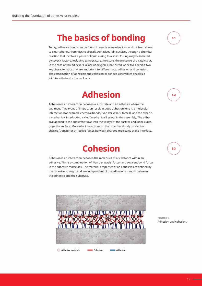
ThebasicsofbondingToday, adhesive bonds can be found in nearly every object around us, from shoes to smartphones, from toys to aircraft. Adhesives join surfaces through a chemical reaction that involves a paste or liquid curing to a solid. Curing may be initiated by several factors, including temperature, moisture, the presence of a catalyst or, in the case of threadlockers, a lack of oxygen. Once cured, adhesives exhibit two keycharacteristicsthatareimportanttodifferentiate:adhesionandcohesion. The combination of adhesion and cohesion in bonded assemblies enables a joint to withstand external loads.
AdhesionAdhesion is an interaction between a substrate and an adhesive where the twomeet.Twotypesofinteractionresultingoodadhesion:oneisamolecular interaction (for example chemical bonds, ‘Van der Waals’ forces), and the other is a mechanical interlocking called ‘mechanical keying’ in the assembly. The adhe-siveappliedtothesubstrateflowsintothevalleysofthesurfaceand,oncecured,grips the surface. Molecular interactions on the other hand, rely on electron sharing/transfer or attractive forces between charged molecules at the interface.
CohesionCohesion is an interaction between the molecules of a substance within an adhesive. This is a combination of ‘Van der Waals’ forces and covalent bond forces intheadhesivemolecules.Thematerialpropertiesofanadhesivearedefinedbythe cohesive strength and are independent of the adhesion strength between the adhesive and the substrate.
5.1
5.2
5.3
FIGURE 4Adhesion and cohesion.
17
Building the foundation of adhesive principles.
Adhesive molecule Cohesion Adhesion

Understandingthebondingprocess
Overview of the bonding process
Each aspect of the bonding process requires the examination and control ofanumberoffactors,butfirstwemustunderstandthefourmainstagesof the bonding process, as shown in Figure 5.
Surface preparationTheadhesionpropertiesofabondjointaresignificantlyinfluencedbythesurfacecharacteristics of the substrates. Proper cleaning and pre-treatment steps are necessary to achieve the strongest adhesive bonds (see Figure 7).
Adhesionisimprovedby:
·Removingunwantedsurfacefilmsbydegreasing or mechanical abrasion
· Activating the surface through the use of a primer
· Changing the surface activity by etching, corona treatment, low plasma treatment, etc.
In order to achieve the optimal mechanical, thermal and chemical performance of an adhesive, the bond surface must be free of contaminants that may affect adhesion to the substrate.
5.4
5.4.1
5.4.2
Surfacepreparation
Application of adhesive
Curing properties and process
Cured performance
FIGURE 5Overview of a typical bonding process.
18 HOW TO INCREASE RELIABILITY AND PREVENT THREADED ASSEMBLY FAILURE
Section5: The basics of adhesives

SOURCE OF CONTAMINATION CONTAMINATION
Manufacturingprocess Release agents, graphite content in cast iron, drawing lubricants
Handling Oils
Environment Moisture, dirt and dust
Machiningprocesses Cuttingfluids,swarf,corrosion inhibitors
Inactivelayers Oxide layers (metals), protective oil, e.g. black oxide steel bolts
Residuesfromgalvanicprocesses Metallic protective coatings like Zinc, Nickel, Phosphate or Chromate
Cleaningprocesses Residues from alkaline baths or industrial cleaners, corrosion inhibitors
TABLE 1Sources of contamination.
19
Depending on the type of contaminant, it can be removed effectively by using the appropriate aqueous-based or solvent-based cleaners.
FIGURE 6Contaminant on substrate surface affecting adhesion.
Adhesive molecule Cohesion Adhesion
Substrate 1
Substrate 2Contaminant
Building the foundation of adhesive principles.

5.4.2.1
20 HOW TO INCREASE RELIABILITY AND PREVENT THREADED ASSEMBLY FAILURE
Cleaning It’s important to clean parts shortly before the adhesive is applied to ensure a contaminant-free surface. Parts that are cleaned far in advance of adhesive application may become re-contaminated prior to bonding if, for example, they are handled with bare hands, gather dust or are exposed to corrosion caused by humidity.
When addressing contamination and selecting the correct cleaner, there are a numberoffactorstoconsider:typeofcontaminant(inorganic/organic),polarity of contaminant, substrate compatibility, part geometry, health and safety regulations and type of process to be used.
Aqueous-basedcleanersAqueous, or water-based cleaning is mainly used when large parts or large quantities of parts are cleaned in one bath process. For optimal performance, aqueous cleaning is usually done at temperatures of 60°C–80°C (140°F–176°F) withaspecifiedimmersioninterval.Thepartsshouldthenberinsedwith demineralized water to prevent mineral deposits, which may affect adhesion. Aqueous cleaners almost always contain corrosion inhibitors, so testing for compatibility with the adhesive is recommended.
Considerationsregardingtheuseofaqueouscleanersarethesignificantdryingtimerequired,theaddedenergyrequiredtospeedthedryingprocess,flashrustand maintaining the bath solution. Another possibility is to add solvents to the cleaner, which reduces the cleaner's evaporation time.
Solvent-basedcleanersSolvent-based cleaning processes usually involve dip baths, closed solvent steam chambers or manual wiping processes (which are most commonly used to clean low volumes of assemblies immediately prior to bonding). Metallic swarf and inorganic components cannot be removed by solvent-based cleaners. However, ifoilorgrease(suchascuttingfluid)iscausingtheinorganicsoilstoadhereto the surface, solvent-based cleaners are effective because they cause contami-nants to lose their adhesion to the surface.
Section5: The basics of adhesives

21
SOLVENT-BASED CLEANER AQUEOUS-BASED CLEANER
Ideal prior to bonding Dilution in water
No residues left on substrate Biodegradable
Impurity dilution (oil, etc.) Cleans organic and inorganic impurities
Immediate evaporation Compatible with most substrates
Good for manual cleaning processes No offensive smell
Can attack plastics (e.g. stress cracking)
Need to mix and monitor specificconcentration
Does not clean inorganic impurities (e.g. salt)
Leaves surface residue, which can affect bonding. Needs rinse stage
Mayhaveflammablelabeling Flash rust
Contain VOCs (regulatory considerations)
Need to monitor contamination of wash solution
TABLE 2Comparison of aqueous and solvent-based cleaners.
SOLVENT-BASED CLEANERS
CONTAMINANT HYDROCARBONS ALCOHOLS KETONES, ESTERS
Cuttingfluid
Corrosioninhibitor
Waxes
Lubricants
Liquidresins
Liquidadhesives
Fingerprints
Siliconeoil
Releaseagent
Recommended cleaning agent
Acceptable cleaning agent
Not recommended as cleaning agent
TABLE 3Efficiency of solvent-based cleaners on contaminants.
Building the foundation of adhesive principles.

22 HOW TO INCREASE RELIABILITY AND PREVENT THREADED ASSEMBLY FAILURE
A good cleaner should remove all contaminants with one cleaning stage and dry quickly at room temperature without leaving residues. It must comply with health and safety standards of the region. User safety and environmental concerns regarding volatile organic compounds (VOC), biodegradability and other consider-ations should be taken into account. Finally, care should be taken to use a cleaner that does not attack the substrate the way solvents, for example, can crack or soften plastics and some alkaline cleaners may aggressively attack aluminium.
AQUEOUS-BASED CLEANERS
CONTAMINANT ALKALINE pH 9-14 NEUTRAL pH 4-10 ACIDIC pH 0-4
Cuttingfluids
Greases
Emulsions
Deepdrawingoil
Deepdrawingsoap
Hardoils
Recommended cleaning agent
Acceptable cleaning agent
Not recommended as cleaning agent
APPLICATION DETAIL IMPORTANT CONSIDERATIONS
TypeofcontaminationThe cleaner should be selected based on the chemistryofthecontamination:polar/non-polar,inorganic/organic.
Process
To eliminate any residue being left behind on the surface, most cleaners need time to evaporate the carrier solution prior to bonding. It is also important toconsiderwhattypeofcleaningprocesswillfitbestin a process (dip tank, spray, wipe).
Partsbeingcleaned The cleaner must be compatible with the parts to ensure it will not negatively impact them.
Healthandsafetyofoperations
Cleaners should comply with health and safety standards to protect workers and the environment.
Section5: The basics of adhesives
TABLE 4Efficiency of aqueous-based cleaners.
TABLE 5Cleaning application details and considerations.

5.4.3
23
Application of adhesiveFor optimal adhesive performance, the correct application is very important. For example, surfaces must be completely wetted with adhesive, and the position of the part and the gap of the desired bond also need to be considered. Vertical or horizontal positioning of the parts will dictate the dispensing methods and the ideal rheology.
Rheology:Viscosity,shearthinning,thixotropyToselectthebestadhesiveforaspecificapplication,rheologicalproperties such as viscosity, shear thinning and thixotropy need to be considered.
Viscosity is the internal resistance of a substance against a deformation caused byanexternalforce.Someadhesivesflowveryeasily,whereasothertypesofadhesivesaresothick,theyhardlyflowatall.Highviscosityessentiallymeans alotofforceisneededtomakeitflow.
Thixotropy, or shear thinning,isthebehaviouroffluidswhoseviscositydecreasesas shear strain increases. Shear thinning is the most common type of non-Newto-nian behaviouroffluidsandisseeninmanyindustrialandeverydayapplications.It is generally observed in polymer solutions (such as adhesives) and molten polymers,aswellasincomplexfluidsandsuspensions,suchasketchup,whippedcream, blood, paint and nail polish. Once the shear load is stopped, the liquid returns to its original viscosity.
FIGURE 7Cutting fluid during drilling operations may affect cure of anaerobic adhesives (threadlockers).
Building the foundation of adhesive principles.

5.4.4
24 HOW TO INCREASE RELIABILITY AND PREVENT THREADED ASSEMBLY FAILURE
DispensingadhesivesThere are a variety of options available for dispensing adhesives, from fully manual to fully automatic and everything in between. Before selecting adispensingmethod,considerthesethreefactors:
• Chemistry type
• Process requirements
• Package size
Inmanycases,thesefactorsmaybedependentuponeachother;forexample,chemistry stability may dictate package size and vice versa. Together, these three factors determine which equipment can be used to dispense an adhesive, and equipment is only chosen after these factors are thoroughly evaluated. Dispensing is discussed in greater detail in section 7.
The curing processMost adhesives go through a curing reaction and transition from a liquid or paste to a solid polymer. There is a direct relationship between the curing action and the development of adhesive strength. Adhesive cure speeds vary greatly from hours to days and will typically be stated on a technical data sheet. Handling time, which is part of the overall cure time, is the time required for partial strength that allows a part to be moved to the next step in a process. Handling strength must be determined by the user based on the assembly process. Cure time is a longer period and is the time required for full or close to full strength. Cure speed can vary with many different factors, such as ambient conditions, catalysts, substrates, gap and the use of activators.
Maximumperformancefromthefinalcuredadhesiveisachievedbyunderstand-ingthefactorsthataffectcureandbymitigatinganypotentialnegativeinflu-ences,suchascureinhibitors,insufficientmixingorenvironmentalfactorsliketemperature and relative humidity.
BondingprocessrequirementsIn a bonding process, the cycle time and the number of pieces to be bonded are determiningfactors.Curespeed,fixturetime,handlingstrengthandclampingtime are also considerations. Manner of application, for example dispensing of beads,dotsandfilms,isdeterminedbytheviscosityandtheflowbehaviourofthe adhesive. The number of bonding positions or process lines is determined by how long the bonded parts must be clamped before they can be moved from one station to another station. In automated processes, in-line monitoring is used to check whether the adhesive has been dispensed, for example, by scanning for a flourescentsubstanceintheadhesive.
Section5:The basics of adhesives

25
Fixturetime Thereareseverallaboratoryteststomeasurefixturetime.Onesuchtestdefines it as the time needed for a standardized bond to reach a shear strength of 0.1 N/mm2 (14.5 psi). Fixture time should not be confused with handling time, whichisspecifiedforeachapplicationindividually.
ThecuredevelopmentprofileisalsocommonlydisplayedonHenkeltechnicaldata sheets, represented in a graph of strength build over time. It is important to consider that any standardized test and cure speed will likely be impacted by factors such as substrate and ambient conditions. OpentimeOpentimeisdefinedasthemaximumtimefromwhentheadhesivehasbeenmixed (two-component), activated or applied and when parts can be assembled.
FullcuretimeFull cure time is the time interval required for an adhesive to reach its full strength. A fully cured adhesive has achieved its intended mechanical and physical properties, like resistance to external forces and resistance to chemicals and ther-malaging.Thefinalstrengthisindicatedintechnicaldatasheetsthroughvarioustest methods and it will be dependent on gap size, environmental temperature and chemicals contacting the adhesive joint.
CuretemperatureTemperature is one of the most important variables when considering adhesive cure characteristics, as the cure speed will be inversely affected by a rise or fall in temperature.Ageneralruleis:forevery10°C(18°F)thatthetemperatureincreas-es, the stated time required for the adhesive to cure will be halved. Conversely, a reduction in temperature of 10°C (18°F) will double the stated cure time. Depend-ing on the chemistry, a point will be reached where curing has nearly stopped. Many adhesives cure fully at room temperature (23°C, 73°F). However, higher curing temperatures cause faster cross-linking of adhesive molecules and a higher grade of cross-linking. In general, lower curing temperatures lead to a slower cure speed and a lower cross-linking. HumiditySome adhesive chemistries are moisture curing and rely on atmospheric humidity. An increase in humidity levels or a substrate with high moisture content will increase the rate of cure for these adhesive types. One caveat for moisture-curing adhesives is that increasing the temperature with the intention of speeding the cure time may have the opposite effect if the humidity is reduced.
Building the foundation of adhesive principles.

5.4.5
TYPE OF LOAD
Mechcanical influences Tensile forcesShear forces
Pressure forcesPeel forces
Torsional forces
Time factor Duration of exposure
Long-term Short-term
Ambient influences Environmental loadTemperature load
Chemical loadCorrosive loadClimactic load
Interaction
Static Dynamic Temp. Media
26 HOW TO INCREASE RELIABILITY AND PREVENT THREADED ASSEMBLY FAILURE
ExothermSome adhesive curing results in an exothermic chemical reaction. Faster curing adhesives and larger adhesive masses will result in higher exotherm temperatures. The shape of the adhesive mass and the thermal conductivity ofthesubstratealsoplaysignificantroles:athinlayerofadhesiveoveralargemetal surface area will have a much lower exotherm than the same mass in a deep pour such as a potting application with less surface area and less thermally conductive surroundings. Care should be taken with fast-curing adhesives to ensure the exotherm remains within acceptable limits for the materials being bonded.
Performance and testing of cured adhesive
The typical cured performance of an adhesive is measured by its resistance to the load and environment of an application. Strength and environmental resistance testing ensures that the adhesive meets design requirements. Henkel recommends that testing be performed for all new adhesive applications under simulated or actual end-use conditions to ensure the adhesive meets or exceeds allrequiredproductspecifications.Sinceassemblyconditionsmaybecriticaltoadhesive performance, it is also recommended that testing be performed on specimens assembled under simulated or actual production conditions.
Section5: The basics of adhesives
FIGURE 8Types of loads acting separately or in combination on bonded joints.

5.4.5.1
5.4.5.2
27
Cured adhesive strengthThe strength of a bonded joint is determined by its resistance to shear, tension, compression, impact, peel and torsion loads. Many standardized test methods can be used to compare the strength of an adhesive and assist in product selection. It is important to consider the types of loads the joint will see in service to ensure that the appropriate test is used to qualify the adhesive.
Effect of environment on cured bondline
Temperature exposure can impact the strength of an adhesive bond joint. Heat aging and hot strength are two types of temperature tests performed to provide an indication of how an adhesive will perform at elevated temperatures.
The hot strength of an adhesive is determined by exposing the bonded joint to an elevated temperature and performing a strength test at the elevated temperature.
Heat aging is conditioning that exposes a bonded joint to an elevated tempera-ture for a given period of time without exposure to stress. It is then brought back to room temperature, 23°C (73°F), and tested to determine the strength at room temperature. Heat aging is best suited to help understand the strength retention in applications when the parts might be subjected to extended periods of elevated temperature but brought back to room temperature prior to being subjected to forces. Custom temperature programs can be designed to simulate and test for real-life heat patterns on assemblies.
Chemical conditioning is conducted in a similar manner to heat aging. A bonded joint is exposed to a chemical or solvent for a given period of time, then removed and tested to determine the effect of this chemical exposure on the bond strength. Chemical conditioning is usually tested at room temperature immediately after removal from the chemical, but the test can also be conducted at an elevated temperature.
While there are many factors that affect the performance of an adhesive over thelongterm,temperatureandchemicalexposurearethemostsignificant influences.Itisimportanttosimulatetheoperatingenvironmentascloselyaspossible in order to accurately predict performance. For example, a chemical at roomtemperaturemaynotaffecttheperformanceofanadhesiveassignificantlyas a chemical at an elevated temperature, as the combined conditions may be moreseverethanthesumoftheindividualinfluences.
Building the foundation of adhesive principles.

THREADED ASSEMBLIES
Section 6
How they work. Why they fail. And how to prevent it.
28 HOW TO INCREASE RELIABILITY AND PREVENT THREADED ASSEMBLY FAILURE
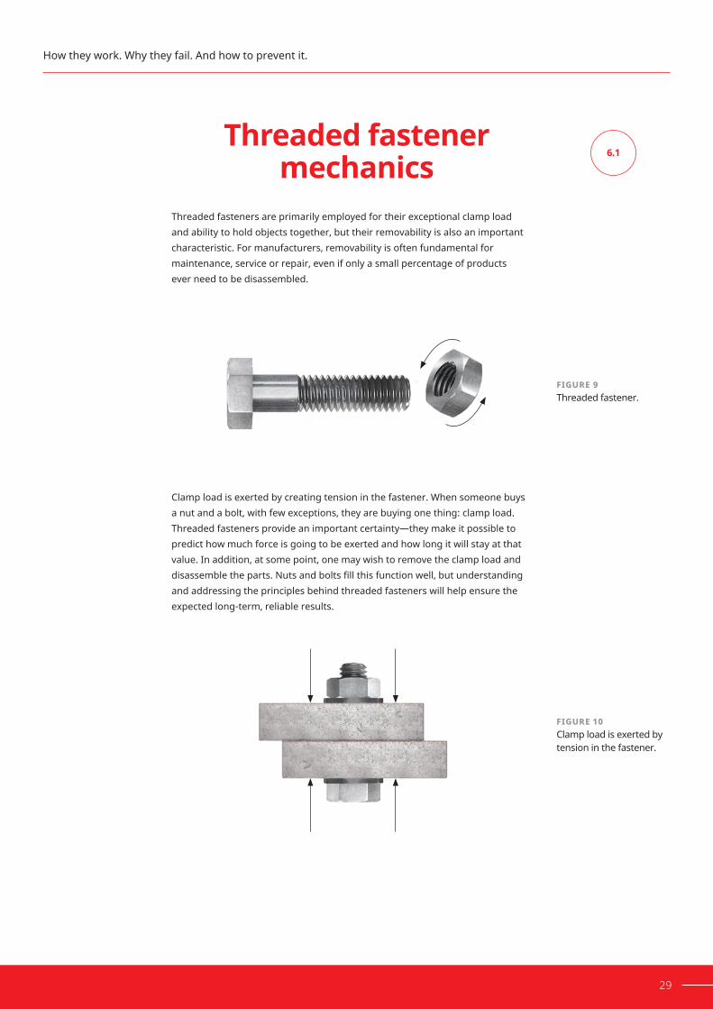
FIGURE 9Threaded fastener.
FIGURE 10Clamp load is exerted by tension in the fastener.
6.1
29
Threadedfastener mechanics
Threaded fasteners are primarily employed for their exceptional clamp load and ability to hold objects together, but their removability is also an important characteristic. For manufacturers, removability is often fundamental for maintenance, service or repair, even if only a small percentage of products ever need to be disassembled.
Clamp load is exerted by creating tension in the fastener. When someone buys anutandabolt,withfewexceptions,theyarebuyingonething:clampload.Threaded fasteners provide an important certainty—they make it possible to predict how much force is going to be exerted and how long it will stay at that value. In addition, at some point, one may wish to remove the clamp load and disassembletheparts.Nutsandboltsfillthisfunctionwell,butunderstandingand addressing the principles behind threaded fasteners will help ensure the expected long-term, reliable results.
How they work. Why they fail. And how to prevent it.

FIGURE 11Torque is the twisting or rotary force in a mechanism.
EQUATION 1Torque-tension - short form.
30 HOW TO INCREASE RELIABILITY AND PREVENT THREADED ASSEMBLY FAILURE
To generate tension in the fastener and consequently clamp load, rotational force, known as torque, is applied.Torqueisdefinedasaforceaboutanaxisofrotation.As a threaded assembly is tightened, torque causes it to twist or rotate. A clock-wise torque to a right-hand threaded part causes one thread to climb the other, andanybearingsurface(suchasaclampingflange)betweenthemaleandfe-male threaded fasteners provides resistance to the continued climbing of threads. Further torquing causes the fastener to elongate or stretch between the bearing surfaces until there is balance between the torque applied and the reaction force due to the sum of the fastener tension and friction.
The relationship between these two forces is called the torque-tension relationship. Broadly speaking, for a given torque load applied to a fastener, aspecifictensionorclamploadwillbegeneratedbythefastener,dependent on friction and the fastener’s diameter. The equilibrium relationship is often expressedmathematically:
T = K D F
T = Torque, N.m (in-lb)
D = Nominal diameter of bolt, m (in)
F = Induced force or clamp load, N (lbf)
K = k-factor (unitless)
The k-factorisanempiricalconstantthatisdependentuponmanyinfluences,including friction, fastener size and material and assembly parameters. It has manynames,including‘nutcoefficient’,‘torquecoefficient’,‘nutfactor‘and‘Kvalue‘. For consistency, this text will use the term ‘k-factor‘ throughout.
Section6: Threaded assemblies

FIGURE 12Correlation of thread pitch and inclined plane.
FIGURE 13Torque applied is stretching the fastener similar to a spring and resulting in clamp load.
6.1.1
31
Inclined planeThe inclined plane is the core concept of a threaded fastener that makes it so useful.Ifweweretorollathreadedfasteneracrossaflatsurfaceandatthesametime ‘unwrap’ the thread, we would be left with something similar to the diagram shown in Figure 12. What was once a helical thread has now become an inclined plane. The angle of this inclined plane is controlled by the thread pitch.
Typically, an M10 x 1.5 mm bolt would produce an inclined plane of approximate-ly 3.0 degrees, and the approximate US equivalent 3/8" x 16 would produce an inclined plane of approximately 3.4 degrees.
When threaded assemblies reach the bearing surfaces, torque is transferred along the long axis of the bolt, causing it to stretch much like a spring. The more torque that is applied, the more the bolt elongates and, in turn, the greater the applied clamp load. If the direction of rotation is reversed, the clamp load is reduced, and the bolt returns to its original length.
How they work. Why they fail. And how to prevent it.
Clamp load
Fastenerelongation
The angle of this inclined plane is controlled by the thread pitch
Coarse
Fine

FIGURE 14Clamp load holds separate objects together to prevent relative movement of the objects.
FIGURE 15Free-body diagram during tightening.
32 HOW TO INCREASE RELIABILITY AND PREVENT THREADED ASSEMBLY FAILURE
The clamp load is used to hold separate objects together and prevent them from moving independently of one another. The force that prevents this movement is friction.
When external forces exceed the surface friction between the two clamped faces, movement occurs. This causes the the fastener to fail because of the core design principle of threaded fasteners, the inclined plane.
In Figure 15, the triangle represents one 360-degree segment of a bolt that has beenfigurativelyunwrapped.Theblockrepresentsanelementofthenutbearingagainsttheinclinedplaneformedbytheunwrappedandflattenedthread(thethread engagement between a nut and bolt). When the torque (T/r) applied to thenutisgreaterthanthefrictionforce(μN),thenutwillclimbtheinclinedplane,tightening the fastener. The friction force is proportional to bolt tension (F). Friction is low until bolt stretching starts to occur and the bolt tension increases. As friction increases with tightening, eventually, equilibrium will be achieved, and the nut will stop.
Section6: Threaded assemblies
T/r
πdₚα
FμN
L
Insufficient clamp load Sufficient clamp load – eliminates movements
N
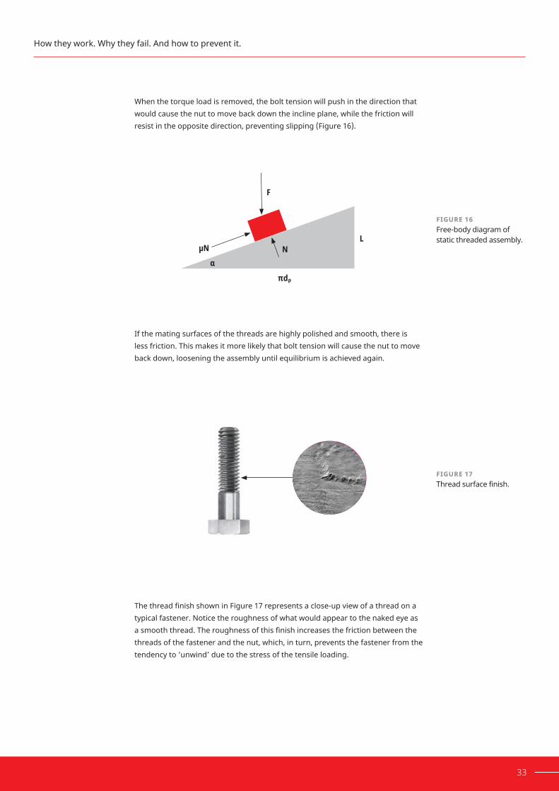
FIGURE 17Thread surface finish.
33
When the torque load is removed, the bolt tension will push in the direction that would cause the nut to move back down the incline plane, while the friction will resist in the opposite direction, preventing slipping (Figure 16).
If the mating surfaces of the threads are highly polished and smooth, there is less friction. This makes it more likely that bolt tension will cause the nut to move back down, loosening the assembly until equilibrium is achieved again.
ThethreadfinishshowninFigure17representsaclose-upviewofathreadonatypical fastener. Notice the roughness of what would appear to the naked eye as asmooththread.Theroughnessofthisfinishincreasesthefrictionbetweenthethreads of the fastener and the nut, which, in turn, prevents the fastener from the tendency to ‘unwind’ due to the stress of the tensile loading.
How they work. Why they fail. And how to prevent it.
FIGURE 16Free-body diagram of static threaded assembly.
πdₚα
F
NL
μN

EQUATION 2Stress in the bolt.
6.2
34 HOW TO INCREASE RELIABILITY AND PREVENT THREADED ASSEMBLY FAILURE
Gettingtheright clampload
One consideration when choosing the right bolt is the expected service loads andhowtheyfluctuate.Whentheclamploadisgreaterthantheexternalloads on the joint, the bolts do not experience cyclic loads and therefore bolt fatigue is minimized.
For a required clamp load ‘F‘, the engineer must choose the appropriate fastener. The relationship between clamp load and the stress in the bolt ‘S‘ is expressed bythefollowingequation:
S = F / A
Where ‘A‘ is the tensile cross-sectional area of the bolt or, more usually, the sum of the areas of several bolts used to provide the clamp load. The size and number of boltscanthenbedeterminedfromthetorquetensionequation:
T = K D F
The target clamp load and equivalent target tensile load for each fastener should be considered within the bolt manufacturer’s guidelines. This value is based on the tensile strength of the fastener classes (metric) and grades (imperi-al) and their tensile cross-sectional area. Manufacturers who wish their fasteners tobeclassifiedwillcertifythattheirmaterialsmeetthegradeorclass.
Hooke’s law allows us to determine how the elongation of a fastener results in clamp load. Under most applications, target loads are kept within the elastic range of the fastener. Torque charts published by bolt manufacturers most often indicate a 75% proof load as the targeted value. This target ensures that the bolt is not stretched past its yield point. Going past the yield point causes permanent bolt elongation (yielding, or plastic deformation) of the fastener. If the bolt material is a precondition, the optimum value of ‘S‘ is known and therefore ‘A‘ can be calculated.
Section6: Threaded assemblies

FIGURE 18Clamp force vs. elongation.
6.3
35
Permanent stretch
Acceptableload range
Target
Elastic stretch0
Yield strength
Ultimate tensile strength
100% Proof (90% yield)
75% Proof
50% Proof
Proof strengthCl
amp
forc
e
ControllingclamploadThere are several accepted methods for measuring clamp load. Threeofthemorecommonmethodsare:
1. Measuring the elongation or stretch of the fastener as it is tightened.
2. Measuring the clamp load directly.
3. Measuring the torque applied to the fastener.
Method 1Measure bolt elongation This method of measuring tension is extremely accurate, with accuracy generally within±5%.Allthreadedfastenersstretchundertheinfluenceoftensileloading.The extent of elongation per unit of increase in load is proportional for fasteners withintheirelasticlimitandisdeterminedby:
A. The tensile strength of the material from which the fastener is made.
B. The diameter of the fastener.
C. The working length of the fastener.
D. The fastener application.
How they work. Why they fail. And how to prevent it.

FIGURE 19Measuring fastener elongation.
FIGURE 20‘Turn of the nut‘.
36 HOW TO INCREASE RELIABILITY AND PREVENT THREADED ASSEMBLY FAILURE
For example, assume an M10 high-tensile steel fastener with a 25 mm (~1") working length elongates 0.05 mm (~0.002") for every 13350 N (~3,000 lbf) of tensile load. Achieving a clamp load of 26,700 N (~6,000 lbf) requires a fastener to be tightened to the point where its overall length is increased by exactly 0.10 mm (~0.004").Thismethodrequirespreciselyflatsurfacesontheendsofthebolt.Themostcommonindustrialfastenersarenotflatattheendofthethreadandwillhave markings on the bolt head to identify its strength. Accurate measurements wouldrequiremachiningthesesurfacesflat.Duetotheaddedtimeandcost,thismethod is therefore unsuitable for most assembly or maintenance operations but is used in some industries and applications where extremely tight tolerances must be maintained.
A variation of this method is the practice of measuring the ‘turn of the nut‘. Using a fastener with a 0.10 mm (0.04 in) pitch as a reference, we know that each 360-degree turn of the nut advances it 0.20 mm (0.08 in) along the axis of the bolt. Assume that each 0.10 mm (0.04 in) elongation of the fastener generates a stress of 146.8 kN (33,000 lbf).
Section6: Threaded assemblies
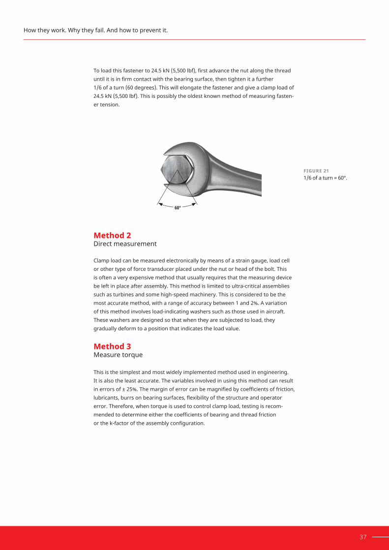
FIGURE 211/6 of a turn = 60°.
37
Toloadthisfastenerto24.5kN(5,500lbf),firstadvancethenutalongthethreaduntilitisinfirmcontactwiththebearingsurface,thentightenitafurther 1/6 of a turn (60 degrees). This will elongate the fastener and give a clamp load of 24.5 kN (5,500 lbf). This is possibly the oldest known method of measuring fasten-er tension.
Method 2Direct measurement Clamp load can be measured electronically by means of a strain gauge, load cell or other type of force transducer placed under the nut or head of the bolt. This is often a very expensive method that usually requires that the measuring device be left in place after assembly. This method is limited to ultra-critical assemblies such as turbines and some high-speed machinery. This is considered to be the most accurate method, with a range of accuracy between 1 and 2%. A variation of this method involves load-indicating washers such as those used in aircraft. These washers are designed so that when they are subjected to load, they gradually deform to a position that indicates the load value.
Method 3Measure torque This is the simplest and most widely implemented method used in engineering. It is also the least accurate. The variables involved in using this method can result inerrorsof±25%.Themarginoferrorcanbemagnifiedbycoefficientsoffriction,lubricants,burrsonbearingsurfaces,flexibilityofthestructureandoperator error. Therefore, when torque is used to control clamp load, testing is recom-mendedtodetermineeitherthecoefficientsofbearingandthreadfriction orthek-factoroftheassemblyconfiguration.
How they work. Why they fail. And how to prevent it.
60°
6.3.2
6.3.1
38 HOW TO INCREASE RELIABILITY AND PREVENT THREADED ASSEMBLY FAILURE
FIGURE 22Clamp load transducer.
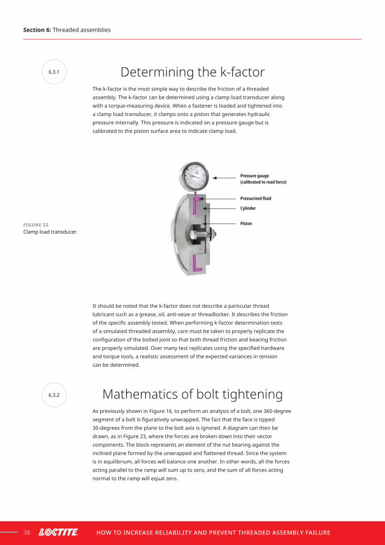
Determining the k-factorThe k-factor is the most simple way to describe the friction of a threaded assembly. The k-factor can be determined using a clamp load transducer along with a torque-measuring device. When a fastener is loaded and tightened into a clamp load transducer, it clamps onto a piston that generates hydraulic pressure internally. This pressure is indicated on a pressure gauge but is calibrated to the piston surface area to indicate clamp load.
Pressure gauge (calibrated to read force)
Pressurized fluid
Cylinder
Piston
It should be noted that the k-factor does not describe a particular thread lubricant such as a grease, oil, anti-seize or threadlocker. It describes the friction ofthespecificassemblytested.Whenperformingk-factordeterminationtests of a simulated threaded assembly, care must be taken to properly replicate the configurationoftheboltedjointsothatboththread friction and bearing friction areproperlysimulated.Overmanytestreplicatesusingthespecifiedhardwareand torque tools, a realistic assessment of the expected variances in tension can be determined.
Mathematics of bolt tighteningAs previously shown in Figure 16, to perform an analysis of a bolt, one 360-degree segmentofaboltisfigurativelyunwrapped.Thefactthatthefaceistipped30-degrees from the plane to the bolt axis is ignored. A diagram can then be drawn, as in Figure 23, where the forces are broken down into their vector components. The block represents an element of the nut bearing against the inclinedplaneformedbytheunwrappedandflattenedthread.Sincethesystemis in equilibrium, all forces will balance one another. In other words, all the forces acting parallel to the ramp will sum up to zero, and the sum of all forces acting normal to the ramp will equal zero.
Section6: Threaded assemblies

FIGURE 23
Free-body diagram of nut and screw thread.
πdₚ
F sin α
F cos α
T/r cos αT/r sin αT/r
F
NL
μN
39
F = Force applied by the bolt
T = Torque applied to bolt
N = Normal force on friction surface
μ=Coefficientoffriction=0.15
dp = Diametrical pitch
α=Helixanglewhosetangent=L/(πdp)
L = Lead of thread
How they work. Why they fail. And how to prevent it.
Σ F‖=0
Σ FN=0
T–r cos a –μN–Fsina=0
T–r sin a =0N – F cos a –
T–r sin a [asmallvaluethatcanbedropped]N = F cos a +
1
2
into T–r cos a – F cos a – F sin a=0
μFcosα+( )Fsinα
cosα cosα T = r
T = rF(μ + tan a)
12

40 HOW TO INCREASE RELIABILITY AND PREVENT THREADED ASSEMBLY FAILURE
Using this formula, let’s calculate the torque required to achieve the same 5000 lbf (22.2kN)clampforceona3/8"coarsethreadanda3/8"finethread(approximatemetric equivalent M10 x 1.5 mm and M10 x 1.25 mm).
3/8"UNC:
dp 0.33
24 24 T = F (μ + tan a) (5000)(0.15+tan(3.50))=14.5lb-ft
3/8"UNF:
dp 0.344
24 24 T = F (μ + tan a) (5000)(0.15+tan(2.20))=13.5lb-ft
Therefore,finethreadedfastenersrequirelesstorquetoachievethesame clamp load.
Byassumingthatthescrewthreadwas100%efficientandtherewasnofriction,you can calculate how much torque is needed to induce the clamp load.
Section6: Threaded assemblies
dp
24 T = F (μ + tan a)
3/8" X 16 UNC1 (COARSE) 3/8" X 24 UNF2 (FINE)
F = 5000 lbf. (given) F = 5000 lbf. (given)
α = 3.5° u = 0.15 α = 2.2° u = 0.15
dp = 0.330" dp = 0.344"
N = 750 lbf. N = 750 lbf.
1UNC-Unifiednationalcoarse 2UNF-Unifiednationalfine
TABLE 6
Fastener parameters.
inlb-ft:3

41
3/8"UNC:
dp 0.33
24 24 T = F (μ + tan a) (5000)(0+tan(3.50))=4.19lb-ft
3/8"UNF:
dp 0.344
24 24 T = F (μ + tan a) (5000)(0+tan(2.20))=2.7lb-ft
Let’s now consider the effects of friction under the head of the bolt.
Again, with a 5000 lbf clamp load and assuming an effective bearing diameter ofthenutof0.400in,thetorquerequiredtoovercomethebearingfrictionis:
T = moment arm × force
De = effective diameter of bearing surfaces (3/8" nut = 0.40")
(0.4)(0.15)(5000)deμF
2424 T = rμF = =12.5lb-ft =
T–r = μF
How they work. Why they fail. And how to prevent it.
TIGHTENING TORQUE 3/8" X 16 UNC1 (COARSE) 3/8" X 24 UNF2 (FINE)
Toovercomethread friction
10.3 lb-ft. (14.0 N.m) 38% 10.8 lb-ft.
(14.6 N.m) 42%
Toovercomeheadfriction
12.5 lb-ft. (16.9 N.m) 46% 12.5 lb-ft.
(16.9 N.m) 48%
Tocreatebolttension
4.2 lb-ft. (5.7 N.m) 16% 2.7 lb-ft.
(3.7 N.m) 10%
Total 27 lb-ft. (36.6 N.m) 100% 26 lb-ft.
(35.3 N.m) 100%
1UNC-Unifiednationalcoarse 2UNF-Unifiednationalfine
TABLE 7
Absorption of tightening torque.

42 HOW TO INCREASE RELIABILITY AND PREVENT THREADED ASSEMBLY FAILURE
Looseningtorque In a similar manner, loosening torque can be computed while accounting for the fact that the thread extension component assists the untightening process.
3/8"UNC:
dp 0.33
24 24 T = F (μ + tan a) (5000)(0.15–tan(3.50))=6.1lb-ft
3/8"UNF:
dp 0.344
24 24 T = F (μ + tan a) (5000)(0.15–tan(2.20))=8.0lb-ft
For total loosening torque, the bolt head friction component remains the same and must be added.
Therefore, for UNC threads, loosening torque is 70% of the tightening torque, and for UNF threads, loosening torque is 80% of the tightening torque.
Section6: Threaded assemblies
LOOSENING TORQUE 3/8" X 16 UNC1 (COARSE) 3/8" X 24 UNF2 (FINE)
Toovercome threadfriction 6.1 lb-ft. (8.3 N.m) 8.0 lb-ft. (10.8 N.m)
Toovercome headfriction 12.5 lb-ft. (16.9 N.m) 12.5 lb-ft. (16.9 N.m)
Totallooseningtorque 18.6 lb-ft. (25.2 N.m) 20.5 lb-ft. (27.8 N.m)
Looseningtorqueas%oftighteningtorque 69% 79%
1UNC-Unifiednationalcoarse 2UNF-Unifiednationalfine
TABLE 8
Loosening torque.

6.3.3
EQUATION 3Long form torque-tension relationship
TABLE 9
Torque absorption in tightening bolt.
43
Influencing factors in achieving correct clamp load
Since torque control is the simplest and most common method for achieving the correct clamp load, it is important to understand why errors of ± 25% are typical. As was calculated in section 6.3, approximately 85–90% of the effort used to tighten a threaded fastener is spent overcoming the friction generated at these points. Only about 10–15% of the effort is used to generate the clamp load producedbythefastenerasstoredenergy.Therefore,torquespecificationsarebased on a prediction of the friction conditions.
The short form of the torque-tension relationship (Equation 1) uses the k-factor tosummarizefrictionforagivenconfiguration.Theanalysisperformedin6.3.2madeanassumptionthatthecoefficientsofthreadfrictionandbearingfrictionwere equal at 0.15. Several long form torque-tension relationships have been derived that break down the geometry further and consider separate and unequal coefficientsoffrictionforthethreadsandthebearingsurfaces.Onesuch exampleisthelongformofEquation1fromISO16047,asshownbelow:
P+1,154×π×μth ×d2 DO + dh1
π − 1,154×μth × Pd2
42 T = F + μb ××
How they work. Why they fail. And how to prevent it.
TOTAL ABSORPTION IN A TIGHTENED BOLT (PERCENT OF TIGHTENING TORQUE)
UNC1 UNF2
Bolttension 16% 10%
Threadfriction 38% 42%
Headfriction 46% 48%
Totaltightening 100% 100%
Looseningtorque 70% 80%
1UNC-Unifiednationalcoarse 2UNF-Unifiednationalfine

44 HOW TO INCREASE RELIABILITY AND PREVENT THREADED ASSEMBLY FAILURE
T = Torque
F = Clamp Force
P = Pitch of the thread
μth=Coefficientoffrictionbetweenthethreads
μb=Coefficientoffrictionbetweenbearingsurfacesunder nut or bolt head
d2 = Basic pitch diameter of thread
DO = Outer diameter of bearing surface
dh = Clearance hole diameter of washer or bearing part
Even though this relationship provides greater detail, the relationship still requires anunderstandingofthecoefficientsofthreadfrictionandbearingfriction.Therearemanyvariablesthatmakethesevaluesdifficulttopredict,includingbutnotlimitedto:
• Substrate or types of materials
•Surfacefinish
• Thread tolerances
• Hole clearances
• Use of washers
• Cleanliness
• Lubrication
• How the threads were produced (cut or rolled)
• Speed of assembly
• Length of the engagement (tapped hole vs standard nut)
• Hardness of bearing materials
FastenervariabilityIt is important to consider variations between fasteners even when they have identicalspecifications.Therearelikelytobesignificantdifferencesbetween manufacturers, batches and even parts within a batch.
InanexperimentconductedbyHenkel,itwasfoundthatsurfacefinish,alongwiththe variances in under-head bolt design varied greatly between manufacturers. When torqued to the recommended level, fasteners from different manufacturers exhibitedsignificantlydifferentclamploads.5
Section6: Threaded assemblies
5. Feeney, Reliable Threaded Fastener Assemblies.

FIGURE 24
Visible variation in fasteners with the same specificationfrom different manufacturers.
FIGURE 25
Average clamp loads for various bolt manufacturers.
45
Hardwarespecifiedas5/8"x11UNCgrade5zinc-platedsteel(approximate metricequivalentisM18x2mm,class8.8)wassourcedfromfivedifferent manufacturers. This grade of fastener was chosen because it was recommended by bolt suppliers as the most commonly sold to general industry customers. Identical hardened washers from a single manufacturer were used throughout the experiment to control this variable. The bolts were torqued in ‘as-received‘ condition using a constant torque value, and the clamp load was measured. The result was a 21% deviation in clamp load between manufacturers, or 4100 lbf (18.2 kN) (see Figure 25).
How they work. Why they fail. And how to prevent it.
10000
12000
8000
6000
4000
2000
0A B C D
21% Range
E
Clam
p lo
ad (l
bs)
Bolt manufacturers
As received

TABLE 10
Thermal conductivity of metals.
46 HOW TO INCREASE RELIABILITY AND PREVENT THREADED ASSEMBLY FAILURE
GallingGalling is wear caused by friction and the buildup of heat between two sliding surfaces. When threaded fasteners are assembled or loosened, heat can be generated very quickly. This effect rapidly changes the friction conditions and may cause the sliding surfaces of the metals to soften and fuse together. A high coefficientoffriction between threads and low thermal conductivity in the metals increase the probability of galling during assembly or disassembly. Table 10 shows the thermal conductivity of common metals used for fasteners. Stainless steel is particularly susceptible to this phenomenon. The threads should either be lubricated or assembly speeds should be reduced to avoid galling.
LubricationLubrication of a threaded assembly will provide more predictable friction and therefore more predictable clamp load. Figure 26 shows a plot of the bolt tension achieved for a given tightening torque on a grade 5 black oxide steel bolt (Class 8.8isapproximateequivalent).Amolybdenumdisulfide-basedanti-seizeprovidedthe highest levels of lubrication, while a solvent-cleaned assembly had the highest level of friction. The use of a lubricant does not eliminate all other variables of friction, nor does it eliminate torque-tension scatter, but it does help to reduce scatter. Therefore, the presence of a lubricant and the underlying friction condi-tionsstillneedtobeknownandshouldbetestedforagivenconfiguration.
It should also be noted that lubrication of an assembly and the reduction of input torque also reduces the bearing friction and thread friction that hold a threaded assembly together, thus making self-loosening more probable. This topic is discussed in greater detail in section 6.4.2.
Section6: Threaded assemblies
THERMAL CONDUCTIVITY OF METALS
METAL BTU/HR•FT•°F (IMPERIAL) WATT/CM•°C (SI)
Copper 231 4
Aluminium 136 2.35
Brass 69 1.19
Zinc 67 1.16
Steel 32 0.55
Stainlesssteel* 8 0.14
* Stainless steel is most likely to gall

47
WashersWashers play an important part in maintaining torque-tension relationships. They are most useful as a means of providing a solid bearing surface for fasteners to work against. By using a hardened washer in conjunction with a threaded fastener, the accuracy of the torque-tension relationship is improvedforthefollowingreasons:
A. The washer generally provides a smooth surface for the bearing surface of the fastener to act against, resulting in lower frictional losses in this area.
B. The washer spreads the fastener load over a greater surface area.
This is particularly important when clamping soft materials such as alloys. The hard material of the fastener tends to ‘settle‘ into the softer alloy over a period, causing loss of clamp load. Softer materials are more likely to ‘yield‘or plastically deform. Spreading the load over a larger area helps reduce the probability of this occurring.
FIGURE 26Torque-tension plot 3/8" UNC grade 5 - black oxide.
500
600
700
800
400
300
200
100
010000 2000 3000 4000 5000 6000
Tigh
teni
ng to
rque
(lb-
in)
Bolt tension (lbf)
Moly based anti-seizeLithium greaseMotor oil Cleaned
How they work. Why they fail. And how to prevent it.
FIGURE 27Embedment of fastener in bolted substrates.
Without a washer, fasteners may settle into the substrate

6.4
6.4.1
6.4.2
48 HOW TO INCREASE RELIABILITY AND PREVENT THREADED ASSEMBLY FAILURE
FastenerfailuresCommon myths about
threaded fastenersAmong design engineers, technicians, reliability experts and mechanics, thesearesomeofthemanycommonmythsaboutthreadedfasteners:
‘A bolt that is properly torqued to standard tightening guidelines will never loosen under any circumstances‘. In fact, external forces may overcome the static friction of the assembly and cause transverse sliding, which may lead to a loss of clamp load in as few as 100 cycles. ‘Fasteners require more torque to loosen than to tighten‘. As was calculated in 6.3.2,looseningtakes70–80%ofthetighteningtorque;itiseasiertogo‘downhill‘than it is to go uphill.
‘IknowitistightenedproperlybecauseItorqueditmyself‘.Thespecifiedtorquemay be reached, but friction may prevent the target clamp load from being achieved.Torquespecificationsrelyonanassumptionoffriction,whichaccountsfor 85–90% of the input.
This section about fastener failures looks at the reasons threaded assemblies fail and helps further invalidate some of these myths.
Why threaded assemblies fail With the amount of friction generated between the mating threads of fasteners, it is hard to imagine that they would lose their clamp load. Unfortunately, they do, and often at a great cost. Fasteners fall out of machinery, causing expensive downtime and repair bills as well as possible injuries. The loss of clamp load in fasteners occurs for many reasons. Some of the most commonreasonsare:
1. Failure to correctly tension the fastener during assembly
2. Excessive tension in the fastener or over-tightening and stripping threads
3. Relative movement between clamped surfaces (the most common reason for loss of clamp load)
4. Relaxation
5. Fatigue effects
6. Corrosion of the assembly
Section6: Threaded assemblies
49
FailuretocorrectlytensionthefastenerduringassemblyFor optimum performance, fasteners must be installed at the correct tension. Atorquewrenchorothersuitabledevicemaybeusedtoachievethespecifiedtorque, but this is only part of ensuring accurate bolt tension is achieved. Thetorquespecificationmayhavebeencreatedusingdifferentassemblies, resulting in different thread friction from the nut and bolt and different bearing friction from the nut or underside of the bolt head against the part or washer. Thetorquespecificationitselfmayhavebeendevelopedwithasinglefastenersize and its K value used to extrapolate for other sizes. On critical assemblies, more accurate means (such as ‘turn of the nut‘ or the fastener elongation method)arespecified.However,evenwhenthesemeasuresaretaken,loss of clamp load and failure are still a possibility.
There is a limit to the tensile loading of any fastener. This is known as the elastic limit. As noted earlier, a fastener begins to stretch when subjected to tensile loading and contracts when the load is released. If a fastener is stretched beyond its elastic limit, it loses its elastic properties and is unable to return to its original length. Consequently, it can no longer provide the intended clamp load. The elastic limit of a fastener lies very close to the yield limit. Common causes for fastener breakage during assembly include incorrectly set clutches on power drivers, the use of torque multipliers on wrenches, uncalibrated torque wrenches or lack of operator training.
The maximum load a fastener can sustain without suffering permanent defor-mationisreferredtoasitsproofload.Forgeneralapplicationinthefield,wheredynamic loading is common and disassembly is often required, fasteners are generally not stressed above 75% of their proof load capabilities. Limiting the load on fasteners accommodates impact and sudden shocks that occur at frequent intervals and prevents failure under these conditions. RelativemovementbetweentheclampedsurfacesRelative movement between the clamped surfaces is the most common reason for loss of clamp load and fastener tension. There are many causes for such movement. Mechanical stress imposed on a structure, such as shock, impact load or bending, may overcome the friction generated between the clamped surfaces. Functional loads, such as internal pressure, side-loaded pivots or shock, are often observed as vibration.
Relativemovementisaproblemthathasplaguedtheindustrysincethefirstthreaded fastener was designed. The reason threaded fasteners are unable to resist the relative movements on their own is directly related to the design principleofallthreadedfasteners:theinclinedplane.
How they work. Why they fail. And how to prevent it.

50 HOW TO INCREASE RELIABILITY AND PREVENT THREADED ASSEMBLY FAILURE
As mentioned previously, bearing friction and thread friction retain the clamp load. In Figure 28, a cross section of a class II threaded assembly is shown (approximate metric equivalent is a 6g-6H tolerance). Class II and 6g-6H fasteners make up the vast majority of all industrial fasteners on the market. As you can see, there is very little metal-to-metal contact between the engaged threads. AclassIIassemblyonlyachieves15%metal-to-metalcontactonthethreadflanksatthislevelofmagnification.Thatmeansthat85%oftheareaisanon-contactsurface and therefore is not being utilized to hold that assembly together.
15% Metal-to-metal
85% Air
Thisclearanceisbydesign;itensuresthemaleandfemalethreadscanbeassembled relatively easily. However, this is also the reason threaded fasteners are able to self-loosen. For an M10 x 1.5, 6g-6H, there will be from 0.032–0.344 mm in lateral clearance (3/8" x 16, Class 2A/B fastener will have 0.0013–0.0114" clearance), which is the amount that the nut and bolt can move relative to each other. This relative movement is called transverse sliding.
An experiment was performed using a simulated object and inclined plane to see how an object moves when a transverse force is applied to the side of the object. When the object was pushed sideways, it slid down and then stopped. With another sideways push, it slid down and stopped again. Subsequently, when there was a continuous sideways push, the object continued to slide down. This experiment demonstrates that if sideways movement is produced in torqued screw threads, the threads can unwind all by themselves. The higher the clamping forces, the less likely there is to be sideways movement, but if sideways movement occurs, the force will unwind the threads regardless of its magnitude.6 In a threaded fastener assembly, this is known as self-loosening.
FIGURE 28Fastener metal- to-metal contact.
Section6: Threaded assemblies
6. Junker, “New Criteria for Self-Loosening.”

51
Causes for relative movementBendingSuppose that a bolted assembly consisting of two parallel members, clamped together, is subjected to a bending load. As the two members bend and create concentric arcs, a difference in length between the inner and outer member emerges. This puts the inner member in compression and the outer member in tension, which creates shear load between the members, resisted by friction. When that friction is overcome, transverse sliding starts and self-loosening can occur.
How they work. Why they fail. And how to prevent it.
FIGURE 29Transverse sliding simulation.
Force
0
TRANSVERSE SLIDING SIMULATION OF TRANSVERSE SLIDING
FIGURE 30Self loosening.
FIGURE 31Bending of clamped member leads to transverse forces.

52 HOW TO INCREASE RELIABILITY AND PREVENT THREADED ASSEMBLY FAILURE
VibrationallooseningVibrationallooseningisoneofthemostdifficultcausesofself-looseningtopredict because it cannot be determined mathematically. Therefore, the best approach to determine the response to an assembly is experimental testing Tests done at NASA/Goddard7 on structures under high vibrational loads of varying frequencyfoundthatvibrationalenergyhadasignificanteffectonthestructuresbeing bolted. If the structure’s response to the vibration caused bending or sideways sliding, possibly from inertial forces, the bolts loosened just as they did under slow sliding from single impacts. The frequency of the vibration determined how quickly the loosening occurred.
One structure tested was a simple composite cantilever beam composed of two steel blades bolted together. Slow movements of bending by hand caused loosen-ing of the ¼" (approximate metric equivalent is M6) bolt after about 100 cycles.
FIGURE 32Vibrational loosening test of standard bolt
FIGURE 33Simple composite cantilever beam composed of two steel blades bolted together.
100
80
60
40
20
01000 200
Clam
p lo
ad in
%
Number of load cycles
Vibration loosening test
Uncoated standard bolt
Section6: Threaded assemblies
7. Kerley, An Application of Retroduction.

53
Rates of thermal expansionAll materials expand and contract with changes in temperature. However, when two clamped members have different thermal expansion rates, a change in tem-perature will cause one member to expand more than the other. In the case of the heads of an inline six automobile engine, differing expansion can cause as much as 1.5 mm (~0.060") total change under extreme temperature cycling. When the change in expansion or contraction is restrained, it induces thermal stress. For a properly tightened assembly, friction provided by the clamp load alone resists the stress, but when the thermal stress exceeds friction, relative movement occurs and therefore transverse sliding and self-loosening begin. For every temperature cycle, the transverse sliding will reduce clamp load, possibly losing all clamp load.
Head Hot
Block
Expansion
Cold
RelaxationWhen a fastener is stretched to the target clamp load, it may only be stretching a few thousandths of an inch or a fraction of a millimeter. This means that any small reduction in stretch will result in a loss of clamp load. Materials under compression, particularly the light alloys which are commonly used in machinery manufacture, may deform under the clamp load from threaded fasteners. As the material under the head of the fastener is displaced, loss of clamp load occurs. If the assembly has been painted prior to assembly or includes a gasket, the problem is further compounded. The loss of clamp load allows leakage to occur, as well as independent movement between the clamped forces. This causes further damage to the gasket by abrasion. The movement also helps the fastener to self-loosen. Once the unwinding process has begun, rapid deterioration of the gasketed joint follows.
How they work. Why they fail. And how to prevent it.
FIGURE 34Differing thermal expansion (head of inline 6 cylinder engine).

54 HOW TO INCREASE RELIABILITY AND PREVENT THREADED ASSEMBLY FAILURE
FatigueeffectsThefatiguestrengthofaboltedjointisevaluatedintwoways:fatigueofthebolt, and fatigue of the bolted material. The properly tightened bolt will not fail by fatigue in a rigid joint. Initial bolt tension will stay relatively constant until the external tension load on the joint exceeds the bolt load.
In an experiment by Fastenal™,8 three identical ½"-13 x 6" grade 8 hex cap screw assembliesweretorquedto3differentclamploads:12,000lbf,9,000lbfand6,000lbf. The recommended clamp load for this fastener is 12,750 lbf. Each assembly was subjected to a 12,000 lbf external load. A load cell was placed under the head of the bolt and another on the frame of a tensile tester. Assembly ‘A’ represents the ideal condition and the joint has been properly tightened. Assembly ‘B’ and ‘C‘ simulate a joint that has either not been properly tightened or has experienced loosening over time. The results show that fasteners with higher clamp loads experience less change in fastener load. When these loads were modelled in axial fatigue tests, the results showed that the properly tightened assembly would never experience a fatigue failure.
FIGURE 35Relaxation of bolted assembly (before and after).
FIGURE 36Fatigue failure experiment.
Section6: Threaded assemblies
F=12,000 lbf F=12,000 lbf F=12,000 lbf
P=12,000 lbf P=9,000 lbf P=6,000 lbfA B C
8. Olson, Preload Influences, 6, 7.

55
If designers do not permit the calculated service load to be greater than the bolt pre-load, the bolt will experience no appreciable stress variation, and without stress variation, there can be no failure by fatigue, regardless of the number of load cycles on the joint.
Thisisnotthecasewhereconsiderableflexibilityispresent.Variablestress inscreworboltfasteningsincreaseswiththeflexibilityoftheconnectedparts. Ifflexibilityistoogreat,thevariablestresspresentmaybehighenoughtocauseeventual fatigue failure of the fastener regardless of the initial bolt pre-load.
CorrosionoftheassemblypreventingdisassemblyThreaded fasteners are employed primarily for their clamp load to hold objects together, but also for their removability. With 85% of the surface area open to air, the joint is open to exposure to salt water, humid air and other corrosive chemicals or environments. These environments will oxidize the metals and can lead to seizure of the assembly. This is an important consideration for maintenance and repairs. The corrosive chemicals and environments described above can act as an electrolyte. When two dissimilar metals are in contact in the presence of an electrolyte, galvanic corrosion occurs. In this situation, one metal becomes the anode and the other metal becomes the cathode. The anode metal will be dissolved into the electrolyte and deposited on the cathode metal. For larger diameter bolts, disassembly may be impossible with the tools available. Oncecorrosionhasoccurred,itisquitedifficulttodisassemblewithhandtools,and the fastener may have to be cut with a torch and replaced. As corrosion also reduces bolt strength, the risk of a catastophic failure increases.
How they work. Why they fail. And how to prevent it.
METAL A B C
Minimumload 12,000 9,000 6,000
Maximumload 12,806 12,322 12,279
Amplitude 806 3,322 6,279
Rratio(min/max) 0.94 0.73 0.49
Cyclestofailure ∞ 434,266 43,314
TABLE 11 Fatigue failure experiment results.
FIGURE 37Corrosion between threads.

6.4.3
56 HOW TO INCREASE RELIABILITY AND PREVENT THREADED ASSEMBLY FAILURE
Traditional mechanical ways to prevent failure
Various methods and devices have been used over the years to reduce or prevent loss of clamp load in threaded fasteners. These solutions mainly assume that the joint is properly tightened to the target clamp load. Any solution for clamp load loss must consider both relaxation and self-loosening.
BoltedjointbestpracticesThe reliability of a bolted joint is increased by implementing the followingbestpractices:
• The surfaces under the bolt head and nut should be smooth and clean. A spot facing operation can be performed if necessary.
• The bolt hole should be chamfered to eliminate burrs and provide clearanceforbolthead-to-bodyfillet.Thisalsoreducesthepotentialstress concentrations and post assembly relaxation.
•Astiffjointandaflexibleboltprovidethemaximumjoint-to-bolt stiffness ratio, minimizing the effects of external loads and temperature change on bolt stress.
• Hard washers should be used to provide a smooth and more predictable surface and distribute contact stresses.
• The bolt and nut should be of identical materials to minimize differential thermal expansion and galvanic corrosion.
• The bolt should extend two full threads past the outer end of the nut when fully tensioned to ensure all nut threads are resisting the tensile load.
• The bolt hole should also be large enough to avoid any interference during assembly but small enough to maximize the bearing surface area and to minimize slip distances.
•Thematingjointsurfacesshouldbeclean,flatandparalleltoeach other to reduce stress concentrations, especially bending stresses, and to minimize relaxation due to settling.
• The bolt hole axis should be perpendicular to join-member surfaces to reduce stress concentrations.
• The bolt head and nut should be readily accessible for accurate clamp load control during tightening. The most accurate tightening tools and appropriate procedures should be used.
• For the tightening process, lubricant should be used for the washer and the threads.
Section6: Threaded assemblies
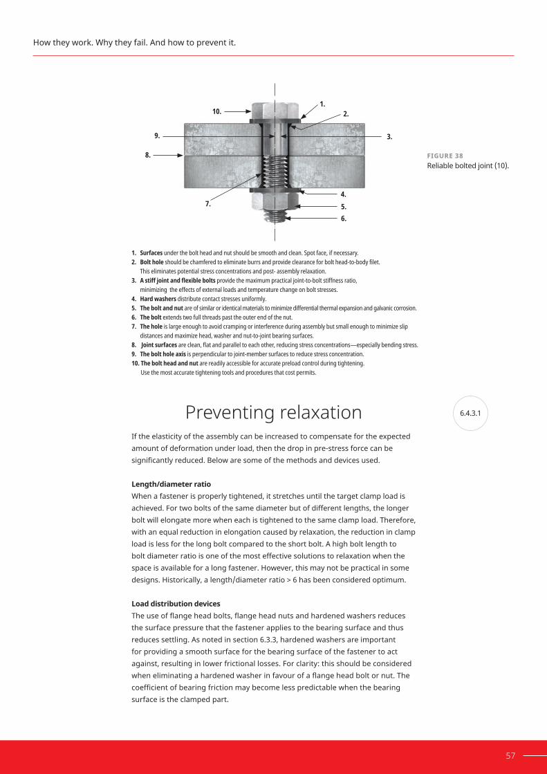
6.4.3.1
57
Preventing relaxationIf the elasticity of the assembly can be increased to compensate for the expected amount of deformation under load, then the drop in pre-stress force can be significantlyreduced.Belowaresomeofthemethodsanddevicesused.
Length/diameterratioWhen a fastener is properly tightened, it stretches until the target clamp load is achieved. For two bolts of the same diameter but of different lengths, the longer bolt will elongate more when each is tightened to the same clamp load. Therefore, with an equal reduction in elongation caused by relaxation, the reduction in clamp load is less for the long bolt compared to the short bolt. A high bolt length to bolt diameter ratio is one of the most effective solutions to relaxation when the space is available for a long fastener. However, this may not be practical in some designs. Historically, a length/diameter ratio > 6 has been considered optimum.
LoaddistributiondevicesTheuseofflangeheadbolts,flangeheadnutsandhardenedwashersreducesthe surface pressure that the fastener applies to the bearing surface and thus reduces settling. As noted in section 6.3.3, hardened washers are important for providing a smooth surface for the bearing surface of the fastener to act against,resultinginlowerfrictionallosses.Forclarity:thisshouldbeconsideredwheneliminatingahardenedwasherinfavourofaflangeheadboltornut.Thecoefficientofbearingfrictionmaybecomelesspredictablewhenthebearingsurface is the clamped part.
How they work. Why they fail. And how to prevent it.
FIGURE 38Reliable bolted joint (10).
1. Surfaces under the bolt head and nut should be smooth and clean. Spot face, if necessary.2. Bolt hole should be chamfered to eliminate burrs and provide clearance for bolt head-to-body filet.
This eliminates potential stress concentrations and post- assembly relaxation.3. A stiff joint and flexible bolts provide the maximum practical joint-to-bolt stiffness ratio,
minimizing the effects of external loads and temperature change on bolt stresses.4. Hard washers distribute contact stresses uniformly.5. The bolt and nut are of similar or identical materials to minimize differential thermal expansion and galvanic corrosion.6. The bolt extends two full threads past the outer end of the nut.7. The hole is large enough to avoid cramping or interference during assembly but small enough to minimize slip
distances and maximize head, washer and nut-to-joint bearing surfaces.8. Joint surfaces are clean, flat and parallel to each other, reducing stress concentrations—especially bending stress.9. The bolt hole axis is perpendicular to joint-member surfaces to reduce stress concentration.10. The bolt head and nut are readily accessible for accurate preload control during tightening.
Use the most accurate tightening tools and procedures that cost permits.
1. 2.
3.
4.5.6.
7.
8.
9.
10.

6.4.3.2
58 HOW TO INCREASE RELIABILITY AND PREVENT THREADED ASSEMBLY FAILURE
SpringwashersSplit ring washers, Belleville™ washers, toothed and fan-type washers, bolts and nuts with pressed-on spring head washers or concave bearing washers are all types of spring washers. However, the clamp load they create is only equal to the clamploadneededtocompressthem,whichissignificantlylessthanthetargetclamp load of a typical structural assembly. These washers are unsuitable for securing bolts of property class 8.8 (grade 5 is the US equivalent) or higher. Under constant compression, over time these devices may relax, losing their ability to create clamp load. Additionally, they cannot prevent self-loosening of the thread-ed assembly if relative movements exist between the stressed parts.
Preventing self-looseningExperts agree that a threaded fastener will not loosen unless the friction forces existing between male and female threads are either reduced or eliminated by some external mechanism acting on the bolt and joint.9 Several solutions to the self-loosening problem have been implemented with varied success.
UseofhightensilestrengthboltsThe friction in a threaded assembly that prevents slipping is directly proportional to the tensile stress of the fastener or the clamp load it is exerting. The use of high-tensile strength bolts may allow clamp loads that are high enough to prevent relative movement. However, higher clamp loads may also worsen relaxation.
FIGURE 39 Spring washer and serrated tooth washer.
Section6: Threaded assemblies
9. Brickford, Introduction to the Design.

59
LockingdevicesMany locking devices have been engineered to prevent self-loosening over theyears.Theycanbecategorizedinto4types:
• Positive locking
• Free-spinning
• Prevailing torque
• Adhesive threadlocking
PositivelockingThe earliest attempts involved using lock wires or split pins in conjunction with castellated nuts, along with bolts that had holes drilled for them to accept these lockingdevices.Theseareeffectivemeasuresforpreventinglossoffasteners;however, they do not prevent the loss of clamp load. In addition, there are other disadvantages that should be considered. Fasteners must be the correct length for the application. Often, lining up the hole in the bolt with a castellation of the nutrequireseitherbackingoffthenutorover-tighteningit.Considerthedifficultyand loss of time to an industry that assembles many components each day, perhaps using thousands of threaded fasteners.
Lock wires are commonly used in applications where a dislodged fastener, ifbroken, may become caught up in other parts of a machine. In instances such as a broken fastener lost in an aircraft engine, the failure could be catastrophic.
FIGURE 40Castellated nut with split pin.
FIGURE 41Locking wires.
How they work. Why they fail. And how to prevent it.

60 HOW TO INCREASE RELIABILITY AND PREVENT THREADED ASSEMBLY FAILURE
These types of locking devices cannot prevent the initial loosening of fasteners, which is the primary cause of most equipment failures. As fastener manufacturing skills and processes have improved, more complex methods of locking have been developed.
Free-spinningtypesThe free spinner device can be a nut, a bolt or a washer and can freely run down with minimal torque. This form of locking device creates interference with the bearingsurfacesduringfinaltighteningandmustbeloadedtoworkeffectively.
The captive-washer types (which can be internal or external) rely upon the sharp edges of the washer digging into the softer bearing surfaces of the fastener and the clamped object. The serrated-tooth variety, both nut and bolt, work in a similar fashion. However, as the serrations are part of the fastener, they need only dig into the bearing surface of the clamped object.
Thereareseveraldisadvantagestothesetypesofdevices:
A. When serrated teeth dig into the bearing surface, more torque is lost to friction. Higher assembly torque is needed to compensate for this loss.
B. If for any reason the locking element is disengaged from the bearing surface or fastener tensile load decreases, the locking action ceases to function.
C. Over a period, the serrations tend to settle into the bearing surfaces, and the clamp load decreases or is lost.
D. The aggressive serrations tend to gouge out the bearing surfaces, particularly on softer alloys, resulting in the need to repair or replace otherwise sound components.
Of the free-spinning types, the serrated-tooth variety, both nut and bolt, are considered more effective.
FIGURE 42 Serrated tooth bolt and nut.
Section6: Threaded assemblies

61
WedgelockingwashersWedge locking washers are a type of free-spinning device, but their function is more unique and their design is more complex. A pair of wedge-locking washers with radial teeth on opposite surfaces grip the surface under the bolt head. The inclined plane of the mated locking wedges is at a greater pitch than the screw thread. To loosen the fastener, the pair of washers must be rotated with their angledteethsliding‘uphill‘overeachother,brieflyincreasingthetensiononthebolt until the peaks pass each other and release this tension. Therefore, tension must increase before loosening can occur. As with other free-spinning devices, the device must be loaded to allow the radial teeth to grip the surface and prevent each washer from rotating relative to the bearing surface of the part and the nut/bolt head. The grip they provide is limited with hardened surfaces, and the radial teeth may damage the bearing surfaces. These devices do not seal the joint and require more torque to obtain the target clamp load. They are effective, but they’re also the most expensive locking mechanism on the market.
Prevailing-torquetypesNyloninsertnutsdonotprovidesufficientthreadfrictiontopreventvibrationalself-loosening, as was shown in Figure 32. While they do prevent the assembly from vibrating apart due to the prevailing torque provided after loss of clamp load, they are ineffective at maintaining clamp load in high vibration environ-ments and do not seal the threads from corrosion.
FIGURE 43Wedge locking washers.
FIGURE 44Damage done to nut surface from radial teeth.
How they work. Why they fail. And how to prevent it.

62 HOW TO INCREASE RELIABILITY AND PREVENT THREADED ASSEMBLY FAILURE
Another locking method involves distorting the thread during manufacture. This is accomplished by indenting certain areas of a nut, or, in the case of setscrewsandsomebolts,byproducingadistorted-threadprofile.
This, in turn, creates a binding effect between male and female threads. Due to the added friction, prevailing-torque type devices require additional torque during tightening to achieve the target clamp load. They also require torque to thread onto the fastener before they engage the bearing surface. This means they cannotbefingertightened.Theymayalsobepronetocorrosion,astheydonotseal the threads, and are limited to a single use.
FIGURE 46Deformed thread nut.
Section6: Threaded assemblies
FIGURE 45Nut with nylon insert.

6.5
6.5.1
63
ThreadlockersAdhesivethreadlockingBy applying adhesive that cures between the threads, the degree of freedom for lateral movements is eliminated as the gaps between the threads are completelyfilled,andatthesametimethreadfrictionisincreasedafterthe adhesive has cured. These adhesives are known as adhesive threadlockers and will be covered in detail in section 6.5
The LOCTITE® Threadlocker solution
The introduction of adhesive threadlocking products eliminated many of the design faults and shortcomings of threaded fasteners. Threadlockers are anaerobic adhesives, which cure to a tough solid state when deprived of atmospheric oxygen (air). The cured product is a thermoset plastic, which cannotbeliquefiedbyheatingandresistsmostsolvents.Theseproducts arespecificallydesignedtolockandsealthreadedcomponents.
Features, benefits and advantages of threadlockers
TorqueresistanceThreadlockers lock more reliably than traditional free-spinning, prevailing-torque or positive lock types because they generate both break-loose and prevailing torque. Break-loose torque is the initial effort required to start rotation of a threaded fastener that has been locked using mechanical or chemical means. Prevailing torque is the effort required to maintain rotation of a threaded fastener after any locking mechanism has been released.
ProtectionfromcorrosionandseizureTraditional locking devices can be used in combination with lubricants and anti-seizecompoundstoprotectagainstcorrosion;however,thereduction in friction caused by these materials may also compromise the function of the assembly. Adhesive threadlockers prevent threaded fastener seizure from corrosion by sealing threads against the entry of moisture.
Controlledstrength The strength of adhesive threadlockers can be controlled by product selection. LOCTITE® Threadlockers are graded by their various strengths into three distinct classifications:Lowstrength,mediumstrengthandhighstrength.Thisversatilityallows removability if desired, or a strong bond that is highly resistant to loads, chemicals and temperature extremes.
How they work. Why they fail. And how to prevent it.

64 HOW TO INCREASE RELIABILITY AND PREVENT THREADED ASSEMBLY FAILURE
ReducedinventoryAsliquids,adhesivethreadlockersfitanysizeassembly.Stocksofvarious sizes of mechanical threadlockers are not required, thereby reducing the cost of large inventories. ThixotropyMany threadlocker grades are thixotropic by design. This feature minimizes the tendency for liquid product to ‘migrate‘ into areas where it is not required or wanted.Thethixotropyalsoimprovesthegap-fillingabilityoftheproduct.
ReducedtorquetensionscatterSome threadlocker grades have a lubricant incorporated in their chemical composition. This is used to reduce the torque tension ‘scatter‘ associated with threaded fasteners. In the fastener variability study discussed in section 6.3.3, which found differences in average clamp load for ‘dry‘ assemblies using 5 bolts withidenticalspecificationsvariedbyupto21%,alubricatingmedium-strength threadlocker was also tested. The results showed that the average scatter was reduced to 12%.
Technical data for lubricants and other thread treating materials will often have the k-factor values listed such as those shown in Figure 48. These values were obtained on 3/8" x 16 (metric approximate M10) nuts and bolts, where the nut was torqued. Both the threads and the nut face were lubricated. Note that the data shownisspecifictotheconfiguration.Anunlubricatedbearingsurface,eithernut or bolt head, can almost double the K value. The variation in friction and therefore in values for K, is wide, since it is the result of extremely high pressure between surfaces that may be rough, smooth, oxidized, chemically treated and/orlubricated.Itshouldalsobenotedthattypicallythereissignificantscatterwithin a batch of fasteners from a single manufacturer. Some threadlocker grades provide equal levels of lubrication to oil and greases, and when they are used, the torque tension scatter is narrowed, which provides consistent bolt tension and
FIGURE 47 Effect of fastener variability with threadlocker.
Section6: Threaded assemblies
10000
12000
8000
6000
4000
2000
0A B C D
21% Range
12% Range
E
Clam
p lo
ad (l
bs)
Bolt manufacturers
As received LOCTITE® 243
AVERAGE CLAMP LOADS FOR VARIOUS BOLT MANUFACTURERS

65
improves reliability (see Figure 48). Materials like graphite and/or molybdenum disulfide-basedlubricantscanprovidelessscatter.Frictionabsorbs80–90%ofthetighteningtorque.Therefore,itisprudenttotestaparticularassemblyconfigu-ration in a torque testing device, as described in section 6.3, to determine proper torque values for assuring good control of bolt tension.
Lockingperformance One of the most well-known and aggressive tests for measuring resistance to self-loosening is the ‘Junker Test‘, also known as the transverse shock test. This test was described in 1969 by German engineer Gerard Junker, who performed extensive research into vibrational loosening.10 The test machine uses an eccentric cam that generates a controlled amount of transverse displacement to the
0.25
0.35
0.3
0.4
0.2
0.15
0.1
0.05
0No lubricant
(dry)Motor oil Lithium
greaseMoly basedanti-seize
Mediumstrength
threadlocker
K-fa
ctor
Thread lubricants
3/8" UNC GRADE 5 – BLACK OXIDE
50% Proof load
75% Proof load
90% Proof load
FIGURE 48 Comparison of k-factor in black oxide 3/8" UNC grade 5 bolts.
How they work. Why they fail. And how to prevent it.
FIGURE 49Torque-tensionscatter:shaded area is with threadlocker, unshaded is without.
Tension
Scatter with adhesive
Scatter with fastener only
Torq
ue
10. Junker, “New Criteria for Self-Loosening.”

66 HOW TO INCREASE RELIABILITY AND PREVENT THREADED ASSEMBLY FAILURE
tightened assembly being tested. A roller bearing between the clamped parts of the assembly allows for free transverse movement, unrestrained by friction. Load sensors in the equipment directly measure the clamp load and can generate a curve showing the loss or retention of various devices. The results provide relevant data for comparing the performance of locking devices in regards to self loosening, but is not used to simulate total design.
As can be seen in Figure 51, LOCTITE® Threadlocker has the best clamp load retention performance among those tested. Most traditional locking devices fail this test, resulting in loss of clamp load.
FIGURE 51Clamp load retention tests - transverse shock machine.
100
80
60
40
20
0400200 600 800 1000
Pre-
stre
ss fo
rce i
n %
Number of load cycles
Bolt with DIN 6797A tooth lock washer
Bolt with DIN 127A spring washer
Uncoated standard bolt
Nut with nylon insert
Standard bolt with LOCTITE® Threadlocker
Bolt with saw-toothed flange
Section6: Threaded assemblies
FIGURE 50 Junkers ‘transverse shock machine’.
Ball bearings (reduce friction)
Load cell (measures clamp load)
Rotating cam (generates vibration)
Sliding plate(transverse vibration)Axial load

6.5.2
67
ImprovedfatigueresistanceTest results indicate that rigid members bolted together by relatively elastic bolts offer the best method to prevent fatigue failure. However, LOCTITE® Threadlockingproductsfillallthevoidsinsidethethread,allowingnoroom for micro-movement of the threaded fastener.
Anaerobic cure mechanismCOMPARATIVE PERFORMANCE OF LOCKING DEVICES
LOCKING DEVICE LUBRICITY
TORQUE-TENSIONCONTROL
LOCKING PERFOR-MANCE
FREE- SPINNING ASSEMBLY
ADJUSTA-BILITY
SIMUL-TANEOUS THREAD SEALING
Lockingdevice Excellent Excellent Excellent Yes Poor Yes
Thread-locker Excellent Excellent Excellent Yes Poor Yes
Plasticnut insert
Fair Fair Poor No Poor No
De-formednut/bolt
Poor Poor Poor No Fair No
Plasticpatch Poor Good Good Yes Good No
Wedgelockingwashers
Poor Good Good Yes Good No
Serratedhead Poor Poor Good Yes Fair No
Anaerobic curing is a chemical reaction that turns a liquid anaerobic threadlocker intoasolidthermosetpolymer.Figure52showsthechemicalreactionsimplifiedinto four steps.
In step 1, the anaerobic adhesive is in a liquid state. The methacrylate monomers are represented by white spheres, the peroxide initiator by red spheres and the oxygen with blue diamonds. As long as oxygen can diffuse through the volume of adhesive, the adhesive will remain liquid.
How they work. Why they fail. And how to prevent it.
TABLE 12 Comparative performance of locking devices.

6.5.3
68 HOW TO INCREASE RELIABILITY AND PREVENT THREADED ASSEMBLY FAILURE
In step 2, when anaerobic adhesive is applied onto the metal surface (the bolt), the adhesive extracts metal ions. These extracted metal ions help decompose the peroxide initiators into highly reactive free radicals. In the presence of air, these free radicals react with oxygen and become unreactive.
Instep3,whenthematingpart(thenut)contactstheadhesiveonthefirstpart, oxygen is no longer available. Additionally, more reactive free radicals are generated, since both metal surfaces are in contact with adhesive. Under these conditions,thereactiveradicalsstartreactingwithmonomers;theyjoin;andthemonomer becomes the free radical, which in turn reacts with another monomer. In this fashion, monomers are being added to form a growing polymer chain.
In step 4, these growing polymer chains eventually react either with another growing polymer chain, forming a crosslinked polymer network, or with other components of the formulation. Both reactions terminate the polymer chain growth. Thus, a very tough and durable thermoset polymer is formed.
Step 1 Step 2
Step 3 Step 4
Peroxides
Oxygen
Free radicals
Metal ions
Monomers
Factors influencing anaerobic curing
When designing a new process, it is important to consider the factors that affect thecuringspeedofananaerobicthreadlocker:substrate,temperatureandgapbetween the substrates.
FIGURE 52Anaerobic cure mechanism.
Section6: Threaded assemblies

6.5.3.1
69
SubstratesMetal ions from the substrate are involved in promoting cure of the adhesive. Hence, metals are the most relevant substrates for anaerobic adhesives. The metal substrate should contain metal ions capable of existing in different oxidation states, for example, copper (Cu+, Cu2+) and iron (Fe2+, Fe3+). In prac-tice, many metal substrates provide the necessary levels of these ions to effective-ly initiate cure of the anaerobic adhesive. Substrates can be grouped into those considered active, which provide a plentiful supply of metal ions, and those that are passive, which provide limited quantities of these metal ions. Substrates used in the manufacture of fasteners can be broadly categorized according to their activity and ability to initiate cure of anaerobic adhesives (Table 13). However, this is only intended to be a guide, as within a category such as stainless steel, activity can vary considerably.
ACTIVE PASSIVE INACTIVE
Copper Brass BronzeIron steelNickel*ManganeseZinc phosphateBlack oxideAluminium alloys (contains Cu)
Low copper aluminiumStainless steelZinc platingZinc dichromateHot dip zinc galvanizing ZincflakecoatedsteelsMagnesiumCadmiumTitaniumChromeNickel*TinMetal oxideChromate layersCeramics*Silver*Gold*
Anodized aluminiumPlasticsPainted and lacquered finishesSilver* Gold*Ceramics*
Fast curing Slow curing Very slow/no curing
*Due to differences in grades, these materials may be included in two categories
SubstratetypesFor anaerobic adhesives, the most important aspect to consider is the composition and cleanliness of the substrate surface. This makes it important tounderstandhowplatingsorfinishesmayaffectanaerobiccuring.Afastenerclassifiedasasteelfastenercouldbetransformedfromanactivesubstratetoa passive one if certain types of coatings are applied, for example, painting the surface. In practical terms, it is relatively easy to check the activity by conducting tests with the adhesive. In general, though, the following overview can serve as a guidefordifferentplatingsandfinishes.
How they work. Why they fail. And how to prevent it.
TABLE 13Anaerobic adhesive cure speed and substrate activity.

70 HOW TO INCREASE RELIABILITY AND PREVENT THREADED ASSEMBLY FAILURE
ZincplatingThis is the most commonly used type of plating and involves deposition of a layer of zinc to the metal by electrochemical means for the purpose of corrosion protection.Thefinishiswhitetoblue-greyincolour.Thistypeoffinishisgenerallyconsidered passive with regard to anaerobic adhesives.
OtherplatingfinishesCadmiumandchrome(chromium)platingfinishesarelessusednowduetoenvironmentalimpact.Nickelplatingprovidesahighlyreflectivefinishwith good corrosion and wear resistance. Anaerobic products generally cure well on this substrate. ChromateChromateisageneraltermforavarietyofsecondaryfinishesappliedtoplatingto further improve corrosion protection. A popular example is zinc dichromate, which is generated by treating a zinc plate with dichromate to produce a yellow finish.Fastenerstreatedinthiswayarelessactivewithregardtoanaerobicadhesives. Nevertheless, many anaerobic adhesives are capable of full cure on these surfaces without the need to use an activator.
HotdipzincgalvanizingThis involves dipping parts in molten zinc. The grey coating provides excellent corrosion protection, but the coating is thick and irregular. For anaerobic products, this is a passive substrate.
PhosphateandoilThisfinishisazincphosphate-basedconversioncoatingcombinedwithanoildipfor improved corrosion protection. For anaerobic adhesives, the substrate itself is active, but the oil should be removed by degreasing for optimum performance.
BlackoxideBlack Oxide, or blackening, is a conversion coating that uses various processes to generate a layer of magnetite (Fe3O4). It is commonly used on ferrous metals for corrosion resistance. The oil present on this type of fastener should be removed by degreasing prior to use with an anaerobic adhesive. The substrate itself is active with regard to anaerobic adhesives. StainlesssteelStainless steel is a popular choice due to its excellent corrosion resistance properties. There are many grades of stainless steel. The 300 series is most often used to produce fasteners, with types such as 304 and 316 most often encountered. Stainless steel often undergoes a passivation process, which involves dipping in nitric acid to remove iron particles. Stainless steel can be considered a passive substrate with regard to anaerobic adhesives, although some adhesives have been developed that cure on many types of stainless steel.
Section6: Threaded assemblies
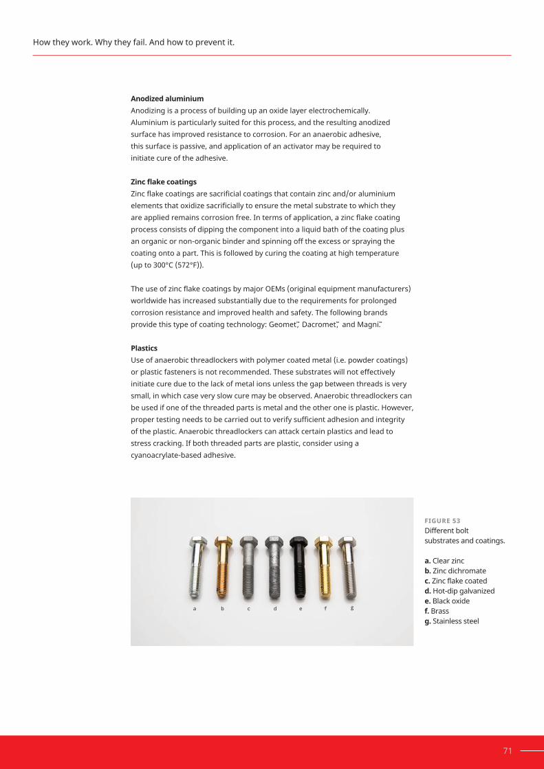
71
AnodizedaluminiumAnodizing is a process of building up an oxide layer electrochemically. Aluminium is particularly suited for this process, and the resulting anodized surface has improved resistance to corrosion. For an anaerobic adhesive, this surface is passive, and application of an activator may be required to initiate cure of the adhesive.
ZincflakecoatingsZincflakecoatingsaresacrificialcoatingsthatcontainzincand/oraluminiumelementsthatoxidizesacrificiallytoensurethemetalsubstratetowhichthey areappliedremainscorrosionfree.Intermsofapplication,azincflakecoatingprocess consists of dipping the component into a liquid bath of the coating plus an organic or non-organic binder and spinning off the excess or spraying the coating onto a part. This is followed by curing the coating at high temperature (up to 300°C (572°F)).
TheuseofzincflakecoatingsbymajorOEMs(originalequipmentmanufacturers)worldwide has increased substantially due to the requirements for prolonged corrosion resistance and improved health and safety. The following brands providethistypeofcoatingtechnology:Geomet™, Dacromet™, and Magni™.
PlasticsUse of anaerobic threadlockers with polymer coated metal (i.e. powder coatings) or plastic fasteners is not recommended. These substrates will not effectively initiate cure due to the lack of metal ions unless the gap between threads is very small, in which case very slow cure may be observed. Anaerobic threadlockers can be used if one of the threaded parts is metal and the other one is plastic. However, propertestingneedstobecarriedouttoverifysufficientadhesionandintegrity of the plastic. Anaerobic threadlockers can attack certain plastics and lead to stress cracking. If both threaded parts are plastic, consider using a cyanoacrylate-based adhesive.
How they work. Why they fail. And how to prevent it.
FIGURE 53 Different bolt substrates and coatings. a.Clear zincb.Zinc dichromatec. Zinc flake coatedd. Hot-dip galvanizede. Black oxidef.Brassg.Stainless steel

6.5.3.2
6.5.3.3
72 HOW TO INCREASE RELIABILITY AND PREVENT THREADED ASSEMBLY FAILURE
Temperature A threadlocker’s cure can be accelerated with increased temperature. Figure 54 showstypicalthreadlockercureprofilesforroomtemperature,elevatedandlowertemperatures. There are limitations to how high/how fast this accelerated cure can be achieved, as above about 150°C (302°F), some chemical components will evaporate and be lost. Heat may also be used to cure anaerobic threadlockers on passive substrates where an activator is not desired. It is important to check the temperature of parts rather than relying on air temperature, as metals may not be equilibrated to room temperature. Additionally, the effect of temperature on viscosity must be considered. At lower temperature, viscosity will be higher, and the threadlocker may not spread on parts as easily as at room temperature. If the productisinpasteform,itmaybedifficulttoapplyatalowertemperature.
Gap between the substrates The curing reaction of the adhesive is slower in larger gaps. Due to the complexity ofthreadedfasteners,thebondgapisdifficulttomeasure.Machinedpinandcol-larspecimenswithdefinedgapswerebondedusingathreadlocker,andtheshearstrength of the assemblies were tested to display the concept of cure speed vs bond gap. Threadlocker adhesive needs the metal ions from the substrate surface in order to cure effectively. Larger bond gaps lead to slower diffusion of the metal ions through the adhesive. For assemblies with large gaps, an activator can be used to reduce cure times.
FIGURE 54Typical temperature dependence of cure behaviour.
80
100
120
60
40
20
01 min 5 min 10 min 30 min 1 h 3 h 6 h 72 h24 h
% of
full s
treng
th on
stee
l
Cure time
40 ˚C
22 ˚C
5 ˚C
Section6: Threaded assemblies

6.5.4
73
Surface preparation for threadlockers
Correct surface pre-treatment is necessary for optimum bonding. Bond strength is determined to a great extent by the adhesion between the joint surfaces and the adhesive, so it’s important to clean surfaces thoroughly. The more thoroughly the surfaces are cleaned, the stronger the adhesive joint will be.
Complete removal of oil, grease, dust and other residual dirt from the bond surface is required for optimum bond strength. Solvents that evaporate without leaving residues are suitable for this. Alkaline or acid-based aqueous cleaning systems almost always contain corrosion inhibitors. If these remain on the cleaned bond surfaces, they may reduce the adhesion of the adhesive. If such cleaning systems are to be used, preliminary tests should always be carried out. In every case, substrates must be thoroughly rinsed or wiped off.
If special degreasing baths are used for larger production runs, it is advisable to preclean very dirty surfaces so the cleaning batch is not contaminated.
ManualcleaningFor manual cleaning, apply a fast evaporating cleaner from its container (pump spray or aerosol) and wet a white, lint-free cloth. Wipe the cloth in one direction only, not back and forth. For nuts and bolts, wrap the cloth around the threads and turn the fastener. Clean the part until it no longer discolours the cloth. For through holes or blind holes, apply cleaner and clear the hole with clean, dry compressed air. It is possible to assist the chemical degreasing process by separating dirt from the surface through mechanical action, for example, by rubbing with a stiff brush.
FIGURE 55 Effect of bond gap on cure speed.
100
75
50
25
01 min 5 min 10 min 30 min 1 h 3 h 6 h 72 h24 h
% of
Full s
treng
th on
stee
l
Cure time
0.05 mm
0.15 mm
0.25 mm
How they work. Why they fail. And how to prevent it.

74 HOW TO INCREASE RELIABILITY AND PREVENT THREADED ASSEMBLY FAILURE
ReuseofafastenerwiththreadlockerWhen a threadlocked bolt is disassembled and needs to be reused, cured threadlocker will need to be removed from the bolt threads. Cured product can be removed with a combination of soaking in a solvent and mechanical abrasion such as a wire brush.
FIGURE 57 Cleaning a bolt with a brush.
FIGURE 56 Cleaning a bolt with LOCTITE® cleaner and wipe.
Section6: Threaded assemblies

6.5.4.1
75
Chemical preparation: Activators
One approach commonly used to improve the performance of LOCTITE® Threadlocker on certain lower activity metals and/or to increase the depth of cure, is to treat the substrate with a solution of a transition metal compound and/or an activator in a volatile solvent.
For some adhesives, an activator is necessary to initiate curing, while for anaerobic threadlockers, the activator is an option to ensure full cure on passive substrates or speed up curing. Unlike primers, activators normally do not improve the adhesion but improve the cohesion of an adhesive by guaranteeing cure.
Activators can be solvent based or solvent free. The activator is applied on one surface, for example on the through hole or on the nut, and the adhesive is applied on the other surface, for example on the bolt thread. The curing process begins immediately after two parts have been joined. The time until the assembly reaches operating strength depends on the adhesive reactivity, the substrate, the gap and the environmental temperature.
Activatorsforthreadlockingadhesivesareusedfor:
• Passive substrates
• Cold temperatures of < 5°C (41°F)
• Curing through larger gaps
• Accelerating cure speed
Activators are particularly useful on passive substrates such as stainless steel, zinc-platedboltsorzincflakecoatings,etc.,astheyarealsousedtoinitiatethecuring process and provide a more robust cure.
In assembly processes, activators are also used to increase cure speed on active metal substrates and to achieve operating strength faster, for example to make it possible to move assembled parts from one assembly station to the next assembly station without affecting the bond line.
Atcoldenvironmentaltemperatures,forexampleinthefieldformaintenanceandrepair applications, the cure speed of anaerobic adhesives can become unaccept-ably long. This is a phenomenon that affects most polymers because the reactivity of polymer crosslinking processes drops at cold temperatures.
How they work. Why they fail. And how to prevent it.

6.6
76 HOW TO INCREASE RELIABILITY AND PREVENT THREADED ASSEMBLY FAILURE
ApplicationofproductThe application of threadlocker to threaded fasteners is an important consid-eration for performance. For maximum reliability, the clearance between the engagednutandboltshouldbefilledwiththeadhesive.Dependingonthe configurationoftheassembly,differenttechniquesareneeded.
Standardnuts/boltsandthroughholesApply a liquid threadlocker onto the bolt and proposed tightened nut engage-mentarea.Toapplyasemi-solidthreadlocker,completelyfilltherootoftheboltthreads at the engagement area. Any excess threadlocker is pushed along with the nut as it is tightened. The volume of threadlocker needed depends on the size of the fastener and engagement area. A few free-falling drops is a typical volume required for an M10 or 3/8" bolt. A minimal amount of threadlocker squeezing outfromthenutandbearingsurfaceinterfaceindicatesthatasufficientvolumeofproducthasbeenusedtofilltheclearance.Ifanassemblyisparticularly susceptible to galling, additional threadlocker may be used along the length of the bolt to lubricate the threads as the nut is threaded on.
PostassemblyWhen a threaded assembly has already been assembled and torqued to the target clamp load, a wicking grade threadlocker can be used. This is particularly suitable for locking adjustment and/or set screws or for preventative maintenance on existing equipment. Product should be applied at the nut and bolt junction, as shown in Figure 59. Avoid touching the bottle tip to the metal.
FIGURE 58Proper application of threadlocker on a through hole. Placement of threadlocker must be closer to the end of the bolt.
Section6: Threaded assemblies

77
BlindholeImproperly applied threadlocker in a blind hole application can cause incomplete coverage of the engaged threads. When product is only applied to the bolt, the liquid threadlocker creates a seal with the female threads and traps air. As the air resists compression, it escapes by pushing threadlocker out through the clearance when the bolt is further engaged, which prevents the threadlocker from enter-ing the blind hole and properly coating the threads. For blind hole applications, drops of liquid threadlocker should be applied down the female threads into the bottom third of the hole or the bottom of the hole. Once the bolt threads become engaged with coated blind hole threads, the air will push threadlocker towards the exit of the hole, creating proper coverage. To ensure complete coverage, it is suggested that threadlocker also be applied to the threads where the threads of the nut and bolt are engaged, as shown in Figure 60.
In rare circumstances, tightening of a fastener into a blind hole can cause hydrau-lic fracturing of the casting. The incompressible liquid threadlocker at the bottom oftheholewillneedtoflowupthethreadstoescape.Greases,anti-seizelubri-cantsandhighviscositythreadlockerswillresistflowingoutandforthisreasonare not recommended for blind hole applications unless assembly speeds are very low. High speed on-torquing devices such as impact guns are best avoided for tightening fasteners into a blind hole, as it will create shock loads.
FIGURE 59Proper post assembly application;wickingthreadlocker.
FIGURE 60 Correct application of threadlocker in a blind hole.
How they work. Why they fail. And how to prevent it.

6.6.1
6.6.1.1
78 HOW TO INCREASE RELIABILITY AND PREVENT THREADED ASSEMBLY FAILURE
Properties of threadlockers Threadlockerpropertiesinanuncuredstateinfluencehowtheproductperformswhen being applied to nuts and bolts, while the properties in a cured state relate to the performance of bonded assemblies in their service environments.
Uncured threadlocker properties
ViscosityViscosityisameasureofresistancetoflowatagivenshearrate.Itisoneof the most important properties to consider in choosing a product. Threadlockers have viscosities ranging from thin, like water, to semi-solid. Some threadlocker productsaredesignedasthixotropicliquids,whichdonotflowwithoutshearforce, preventing drips, but thin out when nuts and bolts are assembled.
OiltoleranceFor optimal adhesion, surfaces should be clean and free of contaminants. However, it is not always realistic to have completely clean surfaces. Many LOCTITE® Threadlockers can still cure and adhere on lightly oil-contaminated surfaces. Testing has demonstrated compatibility with engine oils, corrosion preventionoilsandcuttingfluids,whicharethemostcommoncontaminantsfound on nut and bolt surfaces.
Lubricity How lubrication reduces torque-tension scatter is described in section 6.3.3. Some LOCTITE® Threadlockers have additives that help lubricate the assembly as well as oil and grease. However, the effect of this property is dependent on the threaded fasteners used in the assembly.
FluorescenceThreadlockersmaycontainadditivesthatareflourescentunderUVlight.Thisactsas a quality control or troubleshooting tool to check whether the threadlocker product was used during the assembly.
Section6: Threaded assemblies

6.6.1.2
79
Cured threadlocker properties The performance of threadlocker products is tested using standardized nuts and bolts. The majority of those tests are listed below.
Break-awaytorqueThe torque required to break the bond between the nut and the bolt when rotating an unseated assembly is known as ‘break-away torque‘. For this test, standardized nuts and bolts are assembled using a threadlocker product. The nut is screwed on to expose 2–3 threads on the bolt tip (shown in Figure 62). Thisunseatedassemblyisthencuredforaspecifictimeperiodataspecifictemperature. The torque required to break the bond between the nut and the bolt is measured using semi-automated torque measuring equipment.
Break-loosetorqueSimilartobreak-awaytorque,break-loosetorquereflectsthetorquerequired to break the bond between a standardized nut and the bolt in a seated assembly, typically torqued to 5 N.m. While break-away torque is an indicator of threadlocker strength alone, break-loose torque is more relevant to the clamp load and friction involved in a real-life fastener application.
How they work. Why they fail. And how to prevent it.
FIGURE 61 Assembly for break-away torque measurement.
FIGURE 62 Assembly for break-loose torque measurement.

80 HOW TO INCREASE RELIABILITY AND PREVENT THREADED ASSEMBLY FAILURE
PrevailingtorqueAfter the initial breakage of the bond, the average torque measured during the 360-degree rotation of the nut is known as ‘prevailing torque‘. This torque is measured after the break-away or break-loose torque measurement. A typical output from the break torque measurement is shown in Figure 63. The Y-axis in the plot is the measured torque, and the X-axis is the revolution of the nut measured in degrees. As seen in Figure 63, even after the initial break, there is continued resistance to the nut rotation. The prevailing torque value is normally measured at 180 degrees of rotation.
ShearstrengthofthreadlockersShear strength in a threadlocker is the shear force required to break the threadlocker adhesive bond. High tolerance pin and collar test specimens are used to perform this testing. Detailed information regarding this testing is provided in section 12.6.2. While torque testing uses rotational force to evaluate the adhesive strength in a threaded assembly, this test uses compressive force to push an unthreaded pin that is adhesively bonded to the inner diameter of a collar. Due to the high dimensional tolerances of the specimens, this method provides the best estimate of the true shear strength of threadlockers.
TorqueaugmentationTorque augmentation compares the break-loose torque of an untreated assembly when tightened from 0–90% proof load to the break-loose torque of the same assembly with a locking device. This is an important characteristic that describes how much torque it will take to disassemble a standard bolt and nut assembly when they have been tightened. Threadlockers provide a controlled increase in torque depending on the selected threadlocker strength, whereas most locking devices do not provide torque augmentation.
FIGURE 63 Break-torque and prevail-torque.
80
100
11.5
60
40
20
0
0˚ 45˚ 90˚ 135˚ 180˚ 225˚ 270˚ 360˚315˚
Torq
ue st
reng
th (N
•m)
Revolution
Break torque
Prevailing torque
Section6: Threaded assemblies

81
The value is normally described as a percentage but can also be measured as an absolute torque value increase. In section 6.3.2, we saw that the normal break-loose torque of a coarse thread bolt is approximately 70% of the torque that has beenapplied(forafinethreadbolt,thevalueisapproximately80%).Oncecured,a threadlocker will provide torque augmentation in relation to the strength of the threadlocker. The break-loose torque of low strength threadlockers only increases by approximately 3% over untreated fasteners when tightened to 75% proof load. Medium strength threadlockers provide torque augmentation of approximately 25%, and high strength threadlockers provide approximately 40–75% augmenta-tion depending on other factors.
1. High strength, slow cure. 4. Medium strength. 2. High strength. 5. Low strength. 3. High strength, high lubricity. 6. Normal unlocked 70%.
400
500
600
10
20
30
40
50
60
300
200
100
0 00 100 300200
‘As received’ 3/8" phosphated and oiled grade 5 bolts with ‘as received’ plain steel nuts
75% proof load
400 500 600
Brea
kloo
se to
rque
(lb-
in)
New
ton-
met
re
Tightening torque (lb-in)
Augmentation area
TemperatureresistanceThe effect of high temperature on threadlocker strength is assessed based on hot strength, where a cured assembly is tested at a desired temperature, and heat aging, where a cured assembly is heat-aged at the desired temperature and for the desired time, then tested at room temperature.
HotstrengthThe break-away or break-loose torque measured at an elevated temperature are reported as their hot strength. Usually, assembled and cured nuts and bolts are left in the oven for 1–2 hours before they are measured. This is to ensure that the entire assembly is heated to the desired temperature. Figure 65 plots the results of multiple tests to show the effect of temperature on strength. This testing shows that the threadlocker has the strength to prevent bolt loosening at elevated temperatures.
FIGURE 64 Torque augmentation.
How they work. Why they fail. And how to prevent it.

82 HOW TO INCREASE RELIABILITY AND PREVENT THREADED ASSEMBLY FAILURE
HeatagingAssembled and cured nuts and bolts are aged for the time (as shown on the X-axis inFigure66)atadesiredtemperature.Agedassembliesareremovedatspecifictime points and allowed to cool down to room temperature before break torque measurement. A typical heat-aging plot reported on a technical data sheet is shown in Figure 66.
In some cases, hot strength and heat aging tests are combined. In this test, samples are aged at elevated temperatures and tested at the aging temperature atspecifiedtimeintervals,asshowninFigure67.
FIGURE 66A typical heat aging plot for a threadlocker product.
Section6: Threaded assemblies
100
125
150
75
50
25
00 1000
150 ˚C
180 ˚C
200 ˚C
120 ˚C
100 ˚C
2000 3000 4000 5000
% St
reng
th at
22˚C
Exposure time (hours)
FIGURE 65A typical hot strength plot for a threadlocker product.
80
100
120
60
40
20
00˚ 50˚ 100˚ 150˚ 200˚
% St
reng
th at
22 ˚C
Temperature (˚C)
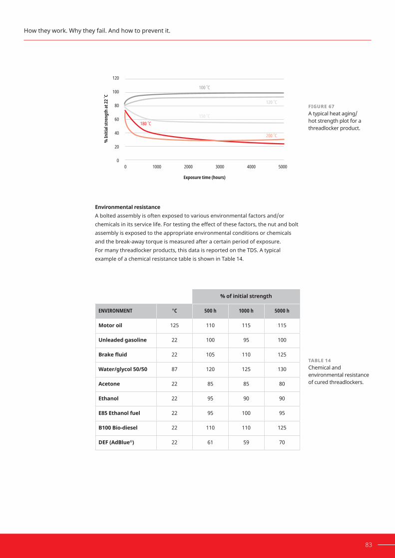
83
EnvironmentalresistanceA bolted assembly is often exposed to various environmental factors and/or chemicals in its service life. For testing the effect of these factors, the nut and bolt assembly is exposed to the appropriate environmental conditions or chemicals and the break-away torque is measured after a certain period of exposure. For many threadlocker products, this data is reported on the TDS. A typical example of a chemical resistance table is shown in Table 14.
FIGURE 67A typical heat aging/ hot strength plot for a threadlocker product.
80
100
120
60
40
20
00 1000
150 ˚C 180 ˚C
200 ˚C
120 ˚C
100 ˚C
2000 3000 4000 5000
% In
itial
stre
ngth
at 22
˚C
Exposure time (hours)
How they work. Why they fail. And how to prevent it.
%ofinitialstrength
ENVIRONMENT °C 500 h 1000 h 5000 h
Motoroil 125 110 115 115
Unleadedgasoline 22 100 95 100
Brakefluid 22 105 110 125
Water/glycol50/50 87 120 125 130
Acetone 22 85 85 80
Ethanol 22 95 90 90
E85Ethanolfuel 22 95 100 95
B100Bio-diesel 22 110 110 125
DEF(AdBlue®) 22 61 59 70
TABLE 14Chemical and environmental resistance of cured threadlockers.

6.6.2
84 HOW TO INCREASE RELIABILITY AND PREVENT THREADED ASSEMBLY FAILURE
ElectricalconductivitySince cured anaerobic threadlocker are thermoset plastic, they do not conduct electricity. However, perfect electrical isolation between nut and bolt cannot be expected. There is always some metal-to-metal contact that can allow the electrical current to pass through.
Product selection
It is critically important to understand the exact requirements of an application in order to provide the best solution. One must consider variables that affect the assembly process as well as variables that affect the performance of the threadlocker during the equipment’s service life.
Howstrongdoesitneedtobe?The strength of a threadlocked assembly is one of the most important consider-ations for selection. Strength is directly related to how much surface area is bonded by the threadlocker. There is a full portfolio of products to meet the strength requirements of various applications. Doestheassemblyneedtoberemovable?If threaded fasteners were designed never to be removed, then only one thread-lockingcompoundwouldbeneeded:thestrongestavailable.Mostassembliesthat are held together with threaded fasteners, however, will at some time be dismantled for repairs, maintenance or adjustments.
Screws are normally tightened using slots or recesses in the head of the screw. The physical size of the slot limits the amount of torque that can be applied to the fastener without causing damage. Furthermore, screws usually have long threaded sections, resulting in large engagement areas. Using a high strength threadlocker under these circumstances will result in the screw being permanent-ly locked into the job. Attempts at removal will usually result in broken screws or damaged screw-head recesses. The torque augmentation capability of low shear strength threadlockers is such that the resulting break-loose torque is only approximately 3% greater than that of an untreated assembly when tensioned to 75% proof load. Where only low assembly torque is used (screwdriver tight), the augmentation percentage will be higher without exceeding fastener torsion strength during disassembly.
FIGURE 68 Engaged length.
Section6: Threaded assemblies
Engaged length

85
Threadlockers used on nuts and bolts are usually higher strength grades than those used for screws. This is because of the relative size of these fasteners and the methods of assembly (i.e. wrenches and sockets), which allow for more torque to be applied without damage to the fastener. In addition, the amount of thread engagement area is reduced. The usual length of engagement for standard nuts and bolts is generally somewhere in the range of 0.8–1.0 times the nominal diameter of the bolt. This, in turn, means that the threadlocking medium must be of a higher strength in proportion to the surface area it acts on. Medium-strength threadlockers will provide torque augmentation approximately 25% greater than the break-loose torque of untreated fasteners when tensioned to 75% proof load. This latter value is generally equal to or slight-ly higher than the recommended tightening torque for the fastener. This is not applicable for bolts threaded into tapped holes, where the engagement length may be much higher.
Studs and highly stressed fasteners usually require threadlockers that offer a greater locking strength than those used for nuts or screws. Break-loose torque issignificantlyhigherthanforuntreatedfastenerswhentensionedto75%proofload. Torque augmentation is around +40 to +55%.
FIGURE 69 Engagement-to-diameter ratio.
FIGURE 70 Stud locking.
How they work. Why they fail. And how to prevent it.
0.8 - 1.0x Diameter
Medium strength
High strength

86 HOW TO INCREASE RELIABILITY AND PREVENT THREADED ASSEMBLY FAILURE
The highest strength threadlockers are recommended in applications where extra chemicalresistanceisrequired,suchasinrefrigerationfittingsandassemblieswhere aggressive solvents are encountered.
High strength
Another type of product that possesses outstanding chemical resistance properties is the slow curing, high viscosity, high-strength threadlocker. The higherviscosityimprovesitsgap-fillingabilities.Thesetendtohavethehighestshear strength of the threadlocking grades, and torque augmentation increases roughly 75% over the break-loose torque for similar untreated fasteners when tensioned to 75% proof load.
How fast does it need to cure?An assembly operation can take only seconds, or it can take hours. The cure speed of the threadlocker can be an important criterion. Additionally, since the surfaces, temperature, gap and cleanliness all have an impact on how fast a threadlocker will cure, each of these parameters must be considered.
Whatarethefastenermaterials?Active metals will cause the threadlocker to cure faster than passive metals. Adhesion to the fastener material may also vary the full cured strength of the assembly. Some products are more sensitive to the surface activity than others. Cure speed vs substrate curves on the technical data sheet provide guidance for this decision. The use of an activator may be required when passive and inactive metalshavebeenspecifiedorwhencurespeedneedstobeaccelerated.
Howlongdoestheassemblyoperationtake?If an assembly operation is very fast, it is important to consider whether the threadlockedassemblyneedstobecuredsufficientlybeforeproceedingtothenext step in the assembly. For a clamped assembly, the metal-to-metal friction often provides handling strength, but heat curing or use of an activator can reduce cure times.
Doestheassemblyrequireatorquesequence?Formanypreciselytensionedassemblies,atorquesequencemaybespecifiedin the tightening procedure. Some of these operations can take minutes or even hours for large equipment. If a threadlocker cures too quickly, it will add friction to the assembly process. Slow curing threadlockers are best suited for these applications.
FIGURE 71 Refrigerant fitting.
Section6: Threaded assemblies

87
What’s the right viscosity?For most applications, a low to medium viscosity threadlocker is well suited for directapplicationtoanutorbolt;however,insomecircumstances,viscositybecomes a primary consideration in product selection.
Isthejointpre-assembled?If the components are pre-assembled, the viscosity of the threadlocker will be a primary consideration. The threadlocker will need to wick into the threads by capillary action, and this requires a wicking grade viscosity.
Arethepartsoverhead?When parts are in an orientation where a liquid would drip off the part, a high viscosity or semi-solid material would be preferred.
Whatdiameterarethefasteners?Threaded fasteners are designed with some clearance between their mating surfaces. As standard bolts have larger clearances between their mating surfaces, theyrequiremoreproducttofillthem.Thethixotropic,highviscosityorsemi-solidvarietieswilleasilyfilltheclearancesinthreadedfastenerswithoutmigratingtoother areas of the assembly.
What are the health and safety requirements?As adhesive threadlocker is a chemical product, health and safety protocols must be considered. The SDS of any threadlocker should be reviewed before use, and exposure limits for workers should be assessed. Threadlockers are generally considered low-risk chemicals. However, some grades of threadlockers have few health and safety concerns. These formulas do not compromise on performance. Innovation in this area is continuous to keep up with changing standards and regulations. Howwillitbeapplied?There are several different ways to apply a threadlocker depending on the situation. A complete procedure should not only specify the product to be used but the method by which it is best applied. If threadlocker is applied to a through hole, blind hole or post-assembly, different methods of application are needed to ensure optimum performance (see 6.6). Automated, semi-automated or manual dispensing equipment can also be used for applying threadlocker and involve a separate list of criteria. An overview of dispensing is covered in the next section.
How they work. Why they fail. And how to prevent it.

6.7
88 HOW TO INCREASE RELIABILITY AND PREVENT THREADED ASSEMBLY FAILURE
Whataretheenvironmentalconditionsaftercure?When it comes to the cured performance of a threadlocker, the major consider-ations are the self-loosening resistance the threadlocker provides and whether the threadlocker will be able to function given the environmental factors, chemical resistance and temperature resistance. LOCTITE® anaerobic products will general-ly resist water, natural or synthetic lubricating oils, fuels, organic solvents and refrigerants. The cross-linked thermoset polymer is particularly stable in view of the geometry of the connection in which they are normally used. As applied tocloselyfittingmetalparts,usuallyonlyafeatheredgeofcuredmaterialafewtenthsofamillimeterinthicknessisexposedtoanyworkingfluid,eveninhigh-pressure sealing applications. Consequently, even the turbulent action of solvents will not erode the hard, cured resin during the life of the assembly.
LOCTITE® Threadlockers, like most organic materials, lose strength at elevated temperatures.Mostshowsignificantstrengthretentionattemperaturesupto150°–180°C (300°–360°F). High temperature formulations can offer working temperatures to 230°C (450°F).
ValidationofassembliesThroughout the design process, testing can be performed to help validate various performancecharacteristics,leadingtostrongerandmorereliablefinalassem-blies. To establish real-part data on developmental product prototypes, Henkel offers comprehensive engineering tests and evaluation capability on customer parts or simulated customer parts. Henkel also has long-term and dynamic test capabilities for simulated or real customer parts.
Performingk-factororcoefficientsoffrictiontestingtoaccuratelydeterminethetighteningtorquespecificationleadstoanassemblywiththedesiredclampload.Knowing that assemblies are exposed to different conditions, testing can also be performedtobetterpredictfinalperformance.
Due to the complexity of the response that vibrations create on a structure, experts believe that testing for vibration resistance on a simulated joint is notsufficient.Theunknowninteractionsandfactorsofasimulatedjointmay give misleading results. If possible, the test should be repeated with the actual joint.
Section6: Threaded assemblies

89
How they work. Why they fail. And how to prevent it.

DISPENSINGSection 7
A variety of dispensing options to accommodatearangeofapplications.
90 HOW TO INCREASE RELIABILITY AND PREVENT THREADED ASSEMBLY FAILURE

7.1
91
A variety of dispensing options to accommodate a range of applications.
Whydispensingequipment?
Dispensing equipment enables the controlled and accurate application of liquid adhesives such as threadlockers. Using dispensing equipment will provide the followingbenefits:
• Better quality
- Improved accuracy of volume dispensed
- Improved placement accuracy of dispensed adhesive
- Improved repeatability
• Reduced cost
- Correct volume applied means less wasted adhesive
- No excess means less clean up and scrap
-Betterapplicationprocessleadstoimprovedefficiency
• Improved health and safety
- Reduced operator contact with the adhesive
Henkel operates on a total solution approachthatprovidesthefollowingbenefits: • Unique individualized customer-centric solutions
• One source for all your needs
- One supplier for the adhesive
- One supplier for the dispensing equipment
- One supplier responsible for the overall application
• The component parts in our equipment that contact the adhesive have been selected for best compatibility with the adhesive technology
•Havingtherightmaterialsfortheadhesiveprovidesconfidencethat the equipment is the right choice for the adhesive and application
• Henkel becomes an extension of a customer’s engineering resource poolforalltheirneeds:
- Adhesive
- Equipment
- Testing
- Product design

7.2
7.2.1
92 HOW TO INCREASE RELIABILITY AND PREVENT THREADED ASSEMBLY FAILURE
DispensingtechnologyTherearetwomaintypesofliquiddispensingtechnology:
1. Pressure/time dispensing
2. Volumetric dispensing
Pressure/time dispensing
Pressure/time systems work by applying air pressure to transport the adhesive from container to dispenser tip. The adhesive is then dispensed for a set time. There are two main types of this system, and each one is suitable for different typesofpacksizes.Thetwomaintypesare:
1. Syringe dispenser – small pack sizes, typically 30 ml
- Air pressure is applied through the top of the syringe, which pushes the piston/plunger towards the bottom of the syringe, dispensing the adhesive out of the dispenser tip.
- No air pressure is applied when not dispensing.
- A vacuum suck-back valve can be applied to the syringe after dispensing so the adhesive is drawn back up the dispenser tip, which prevents drips (2–3 mm max).
- The amount of liquid that is dispensed can change as the syringe empties. This is because the space behind the plunger increases andtakeslongertofillwithair.
2. Two-litre reservoir – larger pack sizes, 250 ml up to 2 l
- Adhesive bottle is placed directly into the reservoir.
- Air pressure is applied to force the adhesive from the bottle up the product feedline to the dispenser valve.
- Low level indicators ensure the adhesive level in the reservoir is monitored to prevent operation when empty.
Section7: Dispensing

93
Needle tip
Adhesive
Piston
Air supply
Adhesive in original container
Pressure relief valve
Product feed line
Air pressure
Thedispensedvolumeisinfluencedbythefollowingfactors:
• Pressure
• Time
• Viscosity (batch or temperature variation)
• Valve stroke (valve dependent)
• Needle diameter
Thecorrelationbetweenadhesiveviscosityandtemperatureisquiteclear:as temperature rises, viscosity drops (Figure 73). Despite variable viscosity, pressure/time dispensing is suitable for most threadlocking applications. When extremely high accuracy is required, alternative volumetric dispensing equipment should be considered.
60
50
40
20
30
1015 20 25 30 35 40
Visc
osity
(Pas
)
Temperature (°C)
FIGURE 72Pressure/time dispensing system diagram.
FIGURE 73Temperature viscosity relationship.
A variety of dispensing options to accommodate a range of applications.
7.2.2
7.2.2.1
94 HOW TO INCREASE RELIABILITY AND PREVENT THREADED ASSEMBLY FAILURE
PRESSURE/TIME DISPENSE
ADVANTAGES DISADVANTAGES
• Easy setup and simple to operate• Reliable, low maintenance• Suits standard LOCTITE® bottles• Suits all viscosities to 100,000 mPa• Lower cost
• Not volumetric• Volume dispensed affected by
temperature• Volume dispensed affected by viscosity• Approximate rule—An increase of
+10°C in temperature reduces viscosity by 50%
Volumetric dispensingVolumetric dispensing systems are designed to positively displace a given volume of adhesive each cycle. This method of dispensing eliminates the variations in dispensed volume experienced due to viscosity changes that may be observed with pressure/time systems.
Therearetwotypesofvolumetricsystems:
1. Peristaltic pumps
2. Progressive cavity pumps
Peristaltic pumpsPeristalticpumpsarecommonlyusedforprecisedispensingoffluids.Thiscan beseenbytheiruseinhospitalsforadministeringfluidsandmedications.Theyare ideal for adhesives, as the adhesive is contained within a feed line with no direct contact with any moving parts.
Peristalticpumpsworkasfollows:
• The product tube is alternately compressed and relaxed.
• Rotating rollers pass along a length of the tube, compressing it completely. This creates a seal between the input (suction) and output (discharge) sides of the pump.
• The relaxing of the tube creates a strong vacuum, which draws the adhesive up to the pump.
• The adhesive does not come into contact with any moving parts.
• This pump is a volumetric pump and thus, dispenses accurate volumes.
TABLE 15Advantages and disadvantages of pressure/time threadlocking dispensing systems.
Section7: Dispensing

7.2.2.2
95
Progressive cavity pumpLOCTITE® uses a progressive cavity system known as an eccentric rotor pump. Thisworksonthefollowingprinciples:
• A rotor, also known as an auger or an Archimedes screw, has a definednumberofsmallcavitiesofafixedshapeandvolume.
• As the rotor rotates, it interfaces with a stator, which has a female Archimedesscrewthreadthatisoffsettothatoftherotor.Thedefinedamount of adhesive is moved from one cavity to the next until it is expelled from the dispenser‘s tip.
•Thismeansthevolumetricflowrateisproportionaltothe rotational speed of the rotor.
•Thismakesitvirtuallyindependentoffluctuationscaused by temperature and viscosity.
• Low pressure air feed can be used, as the pump is self priming.
•Theycanbeadjustedtoprovideacontrolledflowrateorprecise drop size. This is achieved by a separate control unit.
• There are different versions based on minimum volume dispensedandflowrate.
FIGURE 74Internal workings of peristaltic dispensers.
A variety of dispensing options to accommodate a range of applications.
FIGURE 75 Progressive cavity pump.

96 HOW TO INCREASE RELIABILITY AND PREVENT THREADED ASSEMBLY FAILURE
Thedispensedvolumeisinfluencedbythefollowingfactors:
• Rotation speed
• Duration of rotation
The graph below shows that the volumetric system is independent from temperature changes and has improved accuracy and repeatability compared to a pressure/time system.
FIGURE 76Dispense volume comparison between pressure/time and volumetric dispensing.
TABLE 16Advantages and disadvantages of volumetric dispensing system.
250
200
150
50
100
05 10 252015 30 35 40 45
Aver
age d
ispen
se vo
lum
e (m
g)
Temperature (˚C)
Pressure/time
Progressive cavity pump
PROGRESSIVE CAVITY PUMP
ADVANTAGES DISADVANTAGES
• Volumetric• Accuracy +/- 1%• Repeatability > 99%•Accurateandadjustableflowrate
control• Seal-sealing, suck-back to prevent
dripping• Easy to replace parts•Usedforfilledandunfilledproducts• Suitable for low to high viscosity
products
• Higher cost compared to pressure/time system
• Not suitable for highly abrasive products
• Stator is a wear part• Requires an external motor drive
Section7: Dispensing

7.3
7.3.1
7.3.2
97
ManualdispensingTherearethreemainoptionsfordispensingthreadlockerusingamanualprocess:
1. Peristaltic and progressive cavity version hand pumps
2. Digital benchtop peristaltic dispensers
3. A controller/reservoir with a valve
Manual hand pumps
As thread locking is primarily a small drop application, manual hand pumps are an excellent choice for quick and accurate manual application of threadlocker. They are ergonomically designed for ease of use and handling. The hand pump connects directly to standard anaerobic threadlocker bottles, enabling a quick changeover when the bottle requires replacement.
Benchtop digital peristaltic dispensers
This is essentially the same principle as a peristaltic hand pump except the pump is motorized to provide more control and features. It is designed for smallervolumeandpacksizes.Thebenefitsthisbringsoverahandpump orpressure/timesystemareasfollows:
• Air-free dispensing, meaning no air in the adhesive.
• Forward and reverse motor control. This means the bottle can be placed on either side of the motor, and it provides a no suck-back feature for drip prevention.
• Simple and convenient load mechanism for product tube replacement.
• Digital motor speed adjustment and display for better control.
• Digital timer display.
FIGURE 77Hand pumps for manual dispensing of threadlockers.
A variety of dispensing options to accommodate a range of applications.

7.3.3
98 HOW TO INCREASE RELIABILITY AND PREVENT THREADED ASSEMBLY FAILURE
• Programs for multiple different parts can be stored.
•Dispensingisinitiatedbyafingerswitchontheapplicator pen, by a button on the unit or by a foot switch.
• Accurate dispensing from an applicator pen.
• Ideal for small drop dispensing.
Controller/reservoir with valveThese are pressure/time systems and work as previously described in section 7.2.1. They enable dispensing of threadlockers direct from larger bottles (250 ml). They are simple to use, reliable and low cost. A complete system includes the followingitems:
• A controller
• A reservoir
• A handheld valve
•Afingerswitchorafootswitchfordispensingthethreadlocker
For ease of use and to save space, the controller and reservoir can be integrated into one unit.
The system is connected to external power and air supply. This provides control over the time and pressure used for dispensing.
FIGURE 78 Digital benchtop peristaltic dispenser.
Section7: Dispensing

7.4
99
The valve is connected to the controller and actuated via air pressure. There are different types of valves designed to accommodate different viscosities of threadlockeranddifferentflowratecapability.Handheldvalvesgenerallyhaveasingle actuator, which means they open with air pressure and close with spring force. Some valves have stroke control. This can vary the amount the valve opens, allowingeithermoreorlessthreadlockertoflowthroughthevalve.
AutomateddispensingAll controllers, reservoirs and valves can be integrated into either a semi-automat-ic or fully automatic process. A semi-automatic process requires some input from an operator, such as presenting a bolt to a sensor, which triggers the dispensing of threadlocker adhesive from a valve onto the bolt. A fully automatic process is one where there is no input required from the operator, such as when a dispens-ing valve is connected to a robot and is triggered by a higher ranking controller such as a programmable logic controller (PLC). The two main dispensing technologies used for automated dispensing equipment are pressure/time and volumetric.
A variety of dispensing options to accommodate a range of applications.
FIGURE 79 Dual channel controller.

7.4.1
100 HOW TO INCREASE RELIABILITY AND PREVENT THREADED ASSEMBLY FAILURE
Automated Pressure/time system
Apressure/timesystemrequires: • Acontroller—Integrating a semi-automated or automated process
requires a more advanced controller with many more functions, suchasflowsensingandaPLCsignalinterface.
• Areservoir
• Avalve—More robust and industrial types of valves are required for this type of system.
• Accessories(optional)—For example, an advancing slide to move the valve into dispensing position and retract it after dispensing has occurred.
Automatic dispensing valves are connected to the controller and actuated via air pressure.Therearedifferenttypesofvalvesdesignedfordifferentviscosities,flowrate capabilities and suck-back requirements. Automatic dispensing valves are available in single acting and double acting versions. The single acting valves open with air pressure and close by spring force. Double acting valves open and close with air pressure, with an additional spring closure to ensure they are failsafe and close in the event of a loss of air supply. Double acting valves have the added benefitofasuck-backfeature.Thesevalvesalsohavestrokecontroltoadjust theflowbyvaryingtheamountthevalveopens,eitherallowingmoreorlessthreadlockertoflowthroughthevalve.
Section7: Dispensing

101
Flow
Air pressure to open
Spring to close
Fluid inlet
Fluid outlet (open)
No flow
No air pressure
Spring to close
Fluid inlet
Fluid outlet (closed)
Flow
Air pressure to open Fluid inlet
Fluid outlet (open)
No flow
Air pressure to close
Fail safe spring to close
Fluid inlet
Fluid outlet (closed)
A variety of dispensing options to accommodate a range of applications.
FIGURE 81Dual acting valve.
FIGURE 80 Single acting valve.

7.4.2
7.5
102 HOW TO INCREASE RELIABILITY AND PREVENT THREADED ASSEMBLY FAILURE
Volumetric automated systemIfavolumetricsystemisrequiredforgreateraccuracy,itwillrequire:
• Arotorpumpcontroller—This controls pump speed, volume
dispensed, reservoir pressure and low-level warnings.
• Areservoir—As in previous sections.
• Arotorpump—As described in section 7.2.2.2.
Figure 82 shows a volumetric rotorpump and its controller. The reservoir used would be the same as that used for pressure/time systems. As described in section 7.2.1, the rotorpump is fed by adhesive at low pressure, meaning the same reservoir can be utilised.
EquipmentselectionWhen selecting the appropriate dispensing equipment, there are a few things that need to be considered. Automated systems generally use pressure/time, as described in section 7.2.1, or volumetric for higher accuracy, as described in section 7.2.2.2. Knowing how many valves or rotorpumps need to be controlled and the accessories that are required for the dispensing system can also help determine equipment needs. For example, two valves running at the same time for a quick cycle time will require a controller that can control two valves simulta-neously. Some other considerations are listed below.
• Volume of adhesive required per component
• Accuracy of volume dispensed
• Yearly volume of components
Section7: Dispensing
FIGURE 82Reservoir/controller and volumetric pump system utilized for the automation of threadlocking adhesives.

103
• Cycle time
• Number of valves/rotorpumps
• Accessories required
• Semi-automation or full automation required
• Part geometry
• Product viscosity
• Cost/budget
FIGURE 83Decision tree on best dispensing method.
Yes Yes
Application
Highdispensingaccuracy?
Manual handpumps
Progressivecavity
Pressure/time
systemProgressive
cavity
Controller/reservoir
Automaticvalve
Peristaltic
Volumetric progressive
pumpPeristaltic
Controller/reservoir
Rotor pump
Volumetricsystem
Benchtopperistaltic
Controller/reservoir
Foot switch Handheldvalve
Foot switch
Highdispensingaccuracy?
Pressure/timesystem
Manual handpumps
Automatedsystem
required?
Application
Threadlockerpack size
50 ml 250 ml
DropDropNo No
No Yes
A variety of dispensing options to accommodate a range of applications.

104 HOW TO INCREASE RELIABILITY AND PREVENT THREADED ASSEMBLY FAILURE
Itaqui apeliciat volupta tiorunt aute
TROUBLESHOOTINGSection 8
How to diagnose—andprevent— bondingchallenges.

W
8.1
105
hen a failure arises in a bonded joint, it is important to troubleshooting to understand the root cause of the issue so it can be avoided in the future. Three key areas should be investigated:parts,processandproduct(3Ps).
PartsWhat does the failure look like? Failure mode analysis is a key aspect of bonded joint troubleshooting, and the subject will be covered in section 8.1.
ProcessHow was the product applied? How were the parts assembled? How was the adhesive cured?
ProductWas the product within its shelf life?How was the product stored?Has the failure occurred in multiple batches or lots?Is this the correct product for the application?
Continued questioning is an important part of troubleshooting to fully understand the problem. Ask yourself ‘what do you actually know?’. Avoid making assump-tions in answering each question.
FailuremodeanalysisWhen assessing the performance of an adhesive by destructive testing or troubleshooting a failed assembly, the most valuable observations that can be madeareofthefailuremode.Therearethreemainadhesionfailuremodes: adhesive failure, cohesive failure and substrate failure.
AdhesivefailureAdhesive failure occurs when the bonded assembly is subjected to a load that exceeds the adhesion, causing failure at the interface of the adhesive and the bonded parts. This failure mode is visible by the adhesive residue remaining on one of the two parts. In the case of a threadlocker, the adhesive would be completely stuck to either the male or female thread, as shown in Figure 84.
How to diagnose—and prevent—bonding challenges.
FIGURE 84 Adhesive failure.

106 HOW TO INCREASE RELIABILITY AND PREVENT THREADED ASSEMBLY FAILURE
CohesivefailureCohesive failure is when the fracture has occurred within the adhesive itself.In this failure mode, the adhesion strength was not exceeded. As shown in Figure 85, adhesive residue is visible on both the nut and the bolt.
SubstratefailureSubstrate failure is when the load exceeds the strength of one or the other of the bonded parts. This does not suggest failure of the adhesive but is nonetheless undesirable. For a threaded assembly, this may present itself as stripped threads, damaged screw head recesses and sheared screw heads during disassembly.
Section8:Troubleshooting
FIGURE 85 Cohesive failure.
FIGURE 86 Substrate failure.

8.2
107
How to diagnose—and prevent—bonding challenges.
RootcausesTherearethreecommonrootcausesofunexpectedfailure:
IncompletecoverageofthebondareaIncompletecoverageofthebondareacanbeduetoinsufficientapplicationofadhesive, or due to adhesive being pushed out of the adhesive bond joint, either by air displacement or pressure applied to the joint. Many products contain fluorescentadditivesthatallowdetectionunderUVlight.Thiscanbeanimportantfeature to aid in detecting the presence or traces of an adhesive.
InsufficientadhesiontothesubstrateThe second root cause can be observed when adhesive failure is observed on the parts. When adhesive fails on a substrate at a strength lower than expected, therootcauseoftheinsufficientadhesiontothesubstratecanbeduetoincompatibility with the substrate or to contamination. If the contaminant and its source is unknown, analytical science techniques such as infrared spectroscopy or energy-dispersive X-ray spectroscopy (EDS) may be needed to identify it. This willhelpfindthesourcesofuturecontaminationcanbeprevented. IncompletecuringofadhesiveIn failure mode analysis, cohesive failure tells us that the adhesive has successfully bonded to both surfaces. However, it is also possible that the adhesive has not achieved its full cohesive strength. In other words, it has partially cured. In order to achieve the expected strength within an assembly, it is important to make sure that the adhesive is completely cured. There are a variety of reasons why an adhesive would not achieve full cure. Adhesives in contact with some materials can experience interactions that will limit the curing reaction and result ininsufficientcure.Forexample,whenananaerobicmaterialisincontactwithnitrites,acorrosioninhibitorfoundinlubricants,cleanersandprotectionfluids,thecuringreactioncanbeinhibited.Ambienttemperaturescanalsoinfluencethe curing rate of an adhesive. At cold temperatures, most curing reactions will typically slow down, which will result in a slower strength build up than observed at higher temperatures. Part-to-part variations in the dimensions of the bond gap between substrates can also impact the cure speed of the adhesive.
Whentroubleshootingfindstherootcauseofafailure,thesolutiontotheissueisoften easy or simple to implement.

108 HOW TO INCREASE RELIABILITY AND PREVENT THREADED ASSEMBLY FAILURE
Itaqui apeliciat volupta tiorunt aute
SHELF LIFESection 9
How we maintain productperformance.

109
uring the development of each product, a thorough stability study is performed to ensure consistent product performance throughout its shelf life. Appearance, viscosity, cure speed and strength on a controlled
testspecimenaresomeofthequalityspecificationsthataproductmustmeet.Most threadlocker products can be stored at room temperature for two years. The adhesive is stabilized in the package by various means.
PackagingAnaerobic adhesives remain liquid (stabilized) in the presence of oxygen. The anaerobicbottlesareintentionallyfilledhalf-waysotheoxygenintheemptyspace will prevent the threadlocker from curing. Additionally, the bottles are made fromairpermeablelow-densitypolyethylene,ensuringthepresenceofsufficientoxygen to prevent curing.
Air
Threadlocker
AdditionalstabilizersThe adhesive formulation also contains additives to stabilize prematurely generated free radicals and any metal ion contamination.
How we maintain product performance.
FIGURE 87 Illustration showing a half-filled bottle.
D

110 HOW TO INCREASE RELIABILITY AND PREVENT THREADED ASSEMBLY FAILURE
Itaqui apeliciat volupta tiorunt aute
CERTIFICATIONS AND STANDARDS
Section 10
Independent testing toensuresuitability.

10.1
10.2
111
Productcertifyingorganizations
In some markets it is desirable and sometimes mandatory that independent laboratory testing be done to establish the suitability of a material for its intended use. The Underwriter’s Laboratory (UL) and NSF International, originally the NationalSanitaryFoundation,aretwoorganizationsthatprovidecertificationsrelevant to machinery adhesives.
TheUnderwriter’sLaboratory(UL)The UL’s purpose is to evaluate materials, devices, products, equipment, construction methods and systems with respect to hazards that affect life and property. The UL’s approvals do not extend to the products assembled with these materials. Separate approvals must be sought for assembled products. For instance, a gas meter assembled with an approved machinery adhesive needs separate approval even though the sealant is approved for the application.
NSFInternational(NSF)The National Sanitation Foundation does not allow materials in potable water systems or food processors to have extractable chemicals or detectable taste or odor. Machinery adhesives are detectable after cure. However, individual mechanisms using machinery adhesives can be approved after appropriate cleaning and testing.
TeststandardsTestingstandardsandperformancespecificationsformachineryadhesiveshavebeen established by government agencies and industrial organizations in several countries. Henkel’s machinery adhesives are tested according to internationally recognized standards from the International Standards Organization (ISO), United States Military Standards and ASTM International (formerly American Society for Testing and Materials).
InternationalStandardsOrganizationThe ISO is an independent, non-governmental international organization with a membership of many national standards bodies. The organization has standardized many test methods relevant to machinery adhesives, including ISO 10964, ISO 10123 and ISO 16047.
USMilitaryStandardsMilitary standards MIL-S-22473 and MIL-S-46163 were written to establish the requirements and test standards for single-component machinery adhesives. They are intended to be a means of classifying the adhesives and do not address engineeringdesignpurposes.Thesemilitaryspecificationshavebeeninactivatedfor new designs, and ASTM D5363 is the intended replacement.
ASTMInternationalASTM International is a voluntary standards developing organization and has standardized test methods relevant to machinery adhesives, including ASTM D5649,ASTMD4562andASTMD5648-01.ASTMD5363isaspecificationthat also aims to be a means of classifying anaerobic adhesives.
Independent testing to ensure suitability.

112 HOW TO INCREASE RELIABILITY AND PREVENT THREADED ASSEMBLY FAILURE
APPENDIXSection 11

113
Contact Find out how you can put our expertise to work for you. Visit henkel-adhesives.com, andselectyourregiontofindglobaltechnicalsupportforyourfacility.
Chemical compatibilitychart
11.2
11.1
LIQUIDS
Abrasive lubricant + Alcohol + Aluminium potassium +
Abrasive slurry + Allyl alcohol + Aluminium sulphate +
Accumulator acid 10% Amyl alcohol + Amine +
Acetaldehyde + Butyl alcohol + Ammonia anhydride -
Acetamide + Ethyl alcohol + Ammonium bisulphite +
Acetate solvents + Hexyl alcohol + Ammonium borate +
Acetic acid 10% Isopropyl alcohol + Ammonium bromide +
Acetic ether + Methyl alcohol + Ammonium carbonate +
Acetone + Propyl alcohol + Ammonium chloride, sal ammoniac +
Acetyl chloride + Alkaline solution (alkaline salt water) + Ammonium chromate +
Acetyl salicylic acid + Alum + Ammonium copper formate +
Acetylene (liquid) + Chromic alum + Ammonium formate +
Acidic alum earth + Potash alum + Ammonium hyposulphite +
Acrylic acid + Sodium alum + Ammonium iodide +
Acrylonitrile + Alum earth + Ammonium molybdate +
Activated carbon + Aluminium acetate + Ammonium oxalate +
Activated silica + Aluminium bicarbonate + Ammonium persulphate +
Active aluminium oxide + Aluminiumbifluoride + Ammonium phosphate +
Aftershave + Aluminium chloride + Ammonium picrate +
Albumin + Aluminium hydroxide, alum earth + Ammoniumsilicofluoride +
+ = Experience has shown that LOCTITE® products are resistant ° = Preliminary tests or resistance tests are recommended % = LOCTITE® products are only resistant up to the given concentration — = LOCTITE® products are not recommended, or may be used only after evaluation

114 HOW TO INCREASE RELIABILITY AND PREVENT THREADED ASSEMBLY FAILURE
Section11: Appendix
LIQUIDS (CONTINUED)
Ammonium sulphate + Barium hydroxide 10% Bromine cyanide +
Ammonium sulphide + Barium sulphate + Cadmium cyanide +
Ammonium thiocyanate + Battery acid 10% Bromine solution °
Ammoniumflouride + Bauxite (see aluminium) + Bronze cyanide +
Amyl acetate + Beef extract + Butadiene +
Amyl chloride + Beef stock + Buttermilk +
Amylamine + Beer + Butyl acetate +
Aniline + Beet juice or pulp + Butyl alcohol +
Aniline dyes + Bentonite (emulsifying agent) + Butyl amine +
Animal blood + Benzaldehyde, bitter almond oil + Butyl cellosolve +
Animal fat + Benzene acid + Butyl chloride +
Antibiotics + Benzene hexachloride + Butyl ether - dry +
Antichlorine solution + Benzene hydrochloride + Butyl lactate +
Antimony salt + Benzine + Butyraldehyde +
Antimony trioxide + Benzol, benzene + Butyric acid +
Antioxidant agents + Benzotriacide + Butyrile acid 10%
Apple juice, apple wine + Beryllium hydrogen sulphate + Cadmium sulphate +
Argon + Bicarbonate (liquid) + Cadmium
Armeen + Bilge medium + Plating solution +
Arochlorine + Bitter almond oil + Calcium acetate +
Aromatic gasoline + Bleached lime + Calcium bisulphate +
Aromatic solvents + Bleaching bath ° Calcium carbonate +
Arsenic acid + Blood - animal + Calcium chlorate +
Asbestos mass + Blood - human + Calcium chloride +
Ash slurry + Blood substitute + Calcium chloride
Asphalt emulsion + Borax - liquid + Salt solution +
Aureomycine + Bordeaux mixture + Calcium citrate +
Aurous cyanide + Boric acid + Calcium ferrocyanide +
Aviation fuel + Brakefluid + Calcium formate +
Bacitracine + Brandy + Calcium hydroxide +
Bacterial media + Brine Calcium hypochlorite +
Barium + Alkaline + Calcium lactate +
Barium acetate + Electrolytical + Calcium nitrate +
Barium carbonate + for pickling + Calcium phosphate +
Barium chloride + Bromine - Calcium silicate +
+ = Experience has shown that LOCTITE® products are resistant ° = Preliminary tests or resistance tests are recommended % = LOCTITE® products are only resistant up to the given concentration — = LOCTITE® products are not recommended, or may be used only after evaluation

115
LIQUIDS (CONTINUED)
Calcium sulphamate + Chlorinated solvents + Cola syrup +
Calcium sulphate + Chlorinated water + Cold brine +
Calcium sulphite + Chlorinated wax + Common resin in alcohol +
Camphor + Chlorine - dry - Concentrated nitric acid -
Cane sugar (liquid) + Chlorine - liquid - Copper chloride +
Canesugar(refined) + Chlorine bleach - Copper chloride gasoline +
Carbitol + Chlorine dioxide ° Copper cyanide +
Carbon disulphite + Chlorocarbon + Copper naphthenate +
Carbon sugar + Chloroform + Copper pickle +
Carbowax + Chloroform - dry + Copper plating (acidic) +
Carboxyl methyl cellulose + Chlorophyll + Copper plating (alkaline) +
Carnauba wax + Chlorosulphonic acid - Copper sulphate +
Casein + Chocolate syrup + Coppering process (acid) +
Casein water paint + Chrome bath 10% Coppering process (caustic solution) +
Cashew oil + Chromic acid 10% Cottonseed oil +
Castor oil + Chromic acid (50% cold) ° Creosote +
Caustic ammonia, ammonium hydroxide ° Chromic acid (50% hot 40°–80°C) - Creosote oil +
Celane + Chromic acid cleanser 10% Creosotic acid +
Cellosolve + Chromic sulphate + Cuprammonium format +
Cellulose acetate + Chromium - liquid 10% Cyanide solution +
Cellulose pulp + Chromium acetate + Cyanuric chloride +
Cellulose xanthate + Chromium chloride + Cyclohexane +
Cement slurry + Citric acid solution (cold) ° Cylinder oil +
Cement, dry + Citric acid solution (hot) ° DDT +
Cement, liquid + Citrus juice + Detergent +
Cereal oil + Citrus (concentrated) + Developer liquid +
Cereal pulp + Clay + Dextran +
Chalk + Coaltar + Dextrine, starch gum +
Chemical pulp + Coating paint + Diacetone alcohol +
Chestnut mordant + Cobalt, acidic + Diamyl amine +
Chloramine + Cobaltous chloride + Diatom deposits, diatom earth +
Chloric alcohol + Coconut oil + Diazo acetate +
Chlorinated brine + Cod liver oil + Dibromic ethyl +
Chlorinated kerosine + Coffee (concentrated) + Dibutyl phthalate +
Chlorinated paper pulp + Coke dust + Dichlorethyl ether +

116 HOW TO INCREASE RELIABILITY AND PREVENT THREADED ASSEMBLY FAILURE
Section11: Appendix
LIQUIDS (CONTINUED)
Dichlorophenol + Ethylene dichloride + Fuming sulphuric acid -
Dicyandiamide + Ethylene glycol + Furfural +
Dielectric liquid + Excrement, excreta + Gallic acid 5%
Diethyl amine + Face cream + Gallium sulphate +
Diethyl ether + Fatty acid amine + Gamma globuline +
Diethyl glycol + Fatty acids + Gelatine (edible gelatine) +
Diethyl sulphate + Fatty alcohol + Gelatine emulsion +
Diglycol acid + Ferment + Glucol acid +
Dimethyl formamide + Ferric chloride + Glucone acid +
Dimethyl sulphine + Ferricfloc + Glucose, starch sugar +
Dioxan (dry) + Ferric sulphate (10%) + Glue emulsion +
Dioxidene + Ferric sulphate Glutamic acid +
Dipentene pinene + Ferric sulphate (saturated) + Gluten, tirtizine +
Diphenyl + Ferrous nitrate + Glycerine C.P.
Dister lubricant + Fertilizer solution + - USP alkaline solution +
Distilled water + Fibre bagasse + Glycine hypochloride +
Distillery mash + Fine dust (dry) + Glycol acid +
Distillery waste water + Flotation concentrates + Glycol amine +
Drinking water + Fluorides + Glyoxal +
Dyeing liquid + Fluorine gases and liquids + Glyococoll, glycine +
Elaxal bath + Fluorolube + Gold monochloride +
Emulsifiedoils + Flux + Grain pulp +
Enamel + Foam generator + Grain sugar +
Enamel frit + Foam latex + Granodine +
Enzyme solution + Foamite + Grape juice +
Epichloric hydrine + Formaldehyde (cold) + Grape pulp +
Ergosterol solution + Formaldehyde (hot) ° Grapefruit juice +
Ethyl acetate, acetic ether + Formic acid (cold) + Grease lubrication +
Ethyl alcohol, spirit of wine + Formic acid (hot) ° Green potassium soap +
Ethyl amine + Formic acid aldehyde (cold) + Grinding coolant +
Ethyl cellosolve + Formic acid aldehyde (hot) ° Ground siliceous earth +
Ethyl format + Freon (see gases) GRS latex +
Ethyl gasoline + Fruit juices + Hair tonic +
Ethyl silicate + Fuel oil + Halo wax +
Ethylene diamine + Fuming nitric acid - Halogen tin plating +
+ = Experience has shown that LOCTITE® products are resistant ° = Preliminary tests or resistance tests are recommended % = LOCTITE® products are only resistant up to the given concentration — = LOCTITE® products are not recommended, or may be used only after evaluation
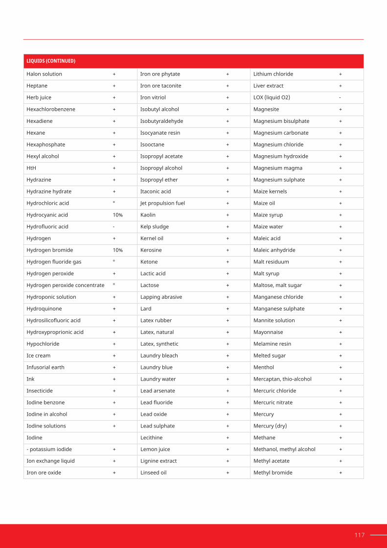
117
LIQUIDS (CONTINUED)
Halon solution + Iron ore phytate + Lithium chloride +
Heptane + Iron ore taconite + Liver extract +
Herb juice + Iron vitriol + LOX (liquid O2) -
Hexachlorobenzene + Isobutyl alcohol + Magnesite +
Hexadiene + Isobutyraldehyde + Magnesium bisulphate +
Hexane + Isocyanate resin + Magnesium carbonate +
Hexaphosphate + Isooctane + Magnesium chloride +
Hexyl alcohol + Isopropyl acetate + Magnesium hydroxide +
HtH + Isopropyl alcohol + Magnesium magma +
Hydrazine + Isopropyl ether + Magnesium sulphate +
Hydrazine hydrate + Itaconic acid + Maize kernels +
Hydrochloric acid ° Jet propulsion fuel + Maize oil +
Hydrocyanic acid 10% Kaolin + Maize syrup +
Hydrofluoricacid - Kelp sludge + Maize water +
Hydrogen + Kernel oil + Maleic acid +
Hydrogen bromide 10% Kerosine + Maleic anhydride +
Hydrogenfluoridegas ° Ketone + Malt residuum +
Hydrogen peroxide + Lactic acid + Malt syrup +
Hydrogen peroxide concentrate ° Lactose + Maltose, malt sugar +
Hydroponic solution + Lapping abrasive + Manganese chloride +
Hydroquinone + Lard + Manganese sulphate +
Hydrosilicofluoricacid + Latex rubber + Mannite solution +
Hydroxyproprionic acid + Latex, natural + Mayonnaise +
Hypochloride + Latex, synthetic + Melamine resin +
Ice cream + Laundry bleach + Melted sugar +
Infusorial earth + Laundry blue + Menthol +
Ink + Laundry water + Mercaptan, thio-alcohol +
Insecticide + Lead arsenate + Mercuric chloride +
Iodine benzone + Leadfluoride + Mercuric nitrate +
Iodine in alcohol + Lead oxide + Mercury +
Iodine solutions + Lead sulphate + Mercury (dry) +
Iodine Lecithine + Methane +
- potassium iodide + Lemon juice + Methanol, methyl alcohol +
Ion exchange liquid + Lignine extract + Methyl acetate +
Iron ore oxide + Linseed oil + Methyl bromide +

118 HOW TO INCREASE RELIABILITY AND PREVENT THREADED ASSEMBLY FAILURE
Section11: Appendix
LIQUIDS (CONTINUED)
Methyl carbitol + Nitrane solution + Tall oil +
Methyl cellosolve + Nitrating acid - Vegetable oils +
Methyl chloride (not adhesive) ° Nitric acid 10% Oleic acid cold +
Methyl ethyl ketone + Nitric acid 20% ° Oleic acid hot +
Methyl isobutyl ketone, isopropyl acetone + Nitric anhydride - Orange juice +
Methyl lactate + Nitroacrylic sulphonic acid + Ore pulp +
Methyl orange + Nitrobenzene, dry + organic dyes +
Methylamine + Nitrocellulose + Oxalic acid +
Methylene dichloride (not adhesive) + Nitrofurane + Ozone, liquid -
Milk + Nitroguanidine + Paint (for vehicles) +
Milk chocolate + Nitrohydrochloric acid - Paint (linseed based) +
Milk of magnesium + Nitroparaffin,dry + Paint (water-soluble) +
Mineral oil, white + Nitrosyl chloride + Palm oil +
Molasses, edible + Norite carbon + Palmitic acid +
Molasses, raw + Nuchar + Paper mill waste +
Molten asphalt + Nutrient fat + Paperpulp
Molten ceramic + Oakite - Bleached +
Moltenparaffin + Oils Chlorinated +
Molten phosphor + Animal oils + Washed and bleached +
Monochloroacetic acid + Castor oil + With amum +
Monochlorobenzene + Coconut oil + With dye +
Monochrome solution (alk.) + Cod liver oil + Paper rags +
Morphalin + Creosotic oil + Paradichlorobenzene +
Mustard + Emulsifiedoils + Paraffinoilkerosine +
Naphtha,paraffin,rockoil + Fish oil + Paraformaldehyde +
Naphthalene + Fuel oil + Peanut oil +
Neoprene emulsion + Grain oil + Pectine +
Neoprene latex + Linseed oil + Penicillin +
Niacin 10% Lubricating oil + Penta-erythrite solution +
Nickel + Mineral oil + Pentachloroethane +
Nickel acetate + Olive oil + Perchloric acid 10%
Nickel ammonium sulphate + Palm oil + Perchloromethyl mercaptan +
Nickelfluoborate + Peanut oil + Perfume +
Nickel plating + Soluble oils + Permanganic acid -
Nickel sulphate + Soybean oil (raw) + Peroxide bleach +
+ = Experience has shown that LOCTITE® products are resistant ° = Preliminary tests or resistance tests are recommended % = LOCTITE® products are only resistant up to the given concentration — = LOCTITE® products are not recommended, or may be used only after evaluation

119
LIQUIDS (CONTINUED)
Persulphuric acid 10% Bronze cyanide + Potassium sulphate, sulphuric potassium +
Petroleum ether + Cobalt (acidic) + Potassium xanthate +
Petroleum spirit alkaline solution + Copper (acidic, caustic) + Pressboard waste +
Petroleum spirit cuprous chloride + Gold cyanide + Propionic acid +
Petroleum spirit acid bath + Iron (acidic) + Propyl alcohol +
Petroleum spirit, acidic + Leadfluoride + Propyl bromide +
Petroleum spirit, white + Nickel + Proteins +
Pharmaceutical substances + Platinum + Pyranol +
Phenol + Silver cyanide + Pyridine +
Phenolic cement + Tin (acidic) + Pyrogallic acid +
Phenolic resins + Zinc (acidic) + Pyrole +
Phenolsulphonic acid + Zinc (caustic) + Pyromellitic acid +
Phenylbetanaphthyl ° Polio vaccine + Quebracho tannin +
Phenylic acid 10% Polyacrylnitrile sludge + Quinone +
Phloroglucinol + Polyphosphoric acid 10% Rayon viscose +
Phosphate ester + Polysulphide liqueur + Riboflavin +
Phosphor sand + Polyvinyl chloride slurry + River water +
Phosphoricacid Porcelain frit + Roccal +
85% hot - Potash, potassium carbonate + Rubber paste +
85% cold ° Potassium acetate + Safrol +
50% hot ° Potassium alum + Sal ammoniac +
50% cold ° Potassium bichromate + Salad dressing +
10% hot ° Potassium bromide + Salad oil +
10% cold + Potassium carbonate + Salicylic acid +
Phosphotungstic acid + Potassium chloride solution + Saliferous soil physiological +
Phthalic acid + Potassium chromate + Salt water +
Picric acid solution + Potassium cyanide solution + Sebum, tallow +
Pine oil + Potassium hydroxide - Selenium chloride +
Pineapple juice + Potassium iodide + Sewage, excreta +
Pit water + Potassium nitrate + Shellac +
Plasma thinners + Potassium permanganate + Shower water +
Platingsubstances: Potassium perchlorate + Silica gel +
Brass cyanide + Potassium persulphate + Silicon liquids +
Bromine + Potassium phosphate + Silicon tetrachloride +
Cadmium cyanide + Potassium silicate + Silver cyanide +

120 HOW TO INCREASE RELIABILITY AND PREVENT THREADED ASSEMBLY FAILURE
Section11: Appendix
LIQUIDS (CONTINUED)
Silver iodide + 70% hot - Sulphonic acids 10%
Silver nitrate + Sodium hypochloride + Sulphonyl chloride +
Slaked lime + Sodium lignosulphonate + Sulphur slurry solution in carbon bisulphide +
Slate (up to 400 mesh) + Sodium metasilicate + Sulphuricacid °
Sloe gin + Sodium monophosphate + 0 - 7% °
Soapsuds (stearates) + Sodium nitrate + 7 - 40% °
Soda pulp + Sodium nitrite (nitrate) + 40 - 75% °
Sodium aluminate + Sodium perborate + 75 - 95% -
Sodium acetate + Sodium peroxide - 95 - 100% -
Sodium benzene sulphonate + Sodium persulphate + Sulphuric iron oxide (10%) +
Sodium bicarbonate + Sodium potassium chloride + Sulphurized oils +
Sodium bichromate + Sodium sulphide + Synthetic latex +
Sodium bisulphite + Sodium stannate Syrup +
Sodium bisulphite + Sodium (preparing salt) + Taconite +
Sodium bromide + Sodium triphosphate + Tall oil +
Sodium carbonate + Sodium xanthate + Tamine +
Sodium chlorite + Solvent naphtha + Tannin, tannic acid (cold) °
Sodium chlorate + Sorbic acid + Tartaric acid, dioxide succinic acid +
Sodium chloride + Sorbit + Tergitole +
Sodium cyanide + Soybean oil + Tetrachloroethylene (dry) +
Sodium dithionite + Spirit of wine + Tetraethyl lead +
Sodium ferrocyanide + Starch + Tetrahydrofurane +
Sodiumfluoride + Starch basis + Tetranitromethane +
Sodium format + Stearic acid + Textile dye +
Sodiumfluate + Sterilizing steam + Textilefinishingoils +
Sodium glutamate + Streptomycine pulp + Textile printing oil +
Sodium hydrosulphide + Styrene + Thiocarbamide +
Sodium hydrosulphite + Styrene-butadienne latex + Thioglycolic acid +
Sodium hydrochloride + Sulpha-sulpho- anhydride + Thionyl chloride +
SodiumHydroxide Sulphamic acid + Thiophosphoryl chloride +
20% cold + Sulphate + Thorium nitrate +
20% hot ° Sulphate hiazole + Thymol, thyme camphor +
50% cold ° Sulphite liquor + Tin (alk.) +
50% hot - Sulphocyanic acid + Tin solder +
70% cold ° Sulphones + Titanium oxide mass +
+ = Experience has shown that LOCTITE® products are resistant ° = Preliminary tests or resistance tests are recommended % = LOCTITE® products are only resistant up to the given concentration — = LOCTITE® products are not recommended, or may be used only after evaluation

121
LIQUIDS (CONTINUED)
Titanium oxide sulphate + Vacuum oil + Sandy +
Titanium tetrachloride + Vanadium pentoxide + Soft +
Tobacco wash solution + Vanilla extract + Sterilized +
Toluene + Varnish + Wax +
Toluol sulphonic acid ° Varnish thinners + Weisberg sulphate plating +
Toluol, methylbenzene + Varsole + Wheat adhesive +
Tomato juice + Vaseline + Whisky +
Tomato ketchup + Versen + Whisky residuum +
Toothpaste + Vinegar + White spirit +
Transile oil + Vinyl acetate + Wine +
Trichloroacetic acid + Vinyl chloride latex emulsion + Wort, malt extract +
Trichloroethane + Vinylha + Xylene, dimethyl-benzene +
Trichloroethylene + Vitamins in oil + Zeolite water +
Triethanolamin + Washing soda + Zinc alk. (cyanide) +
Triglycol + Water Zinc bromide +
Triorthocresylphosphate + Under pH7* + Zinc chloride +
Trioxane + pH7 to pH8 + Zinc cyanide (alk.) +
Tungstic acid anhydride + (Alk.) over pH8* + Zinc galvanizing +
Turpentine + Boiling ° Zinc oxide +
Turpentine oil + Carbonated + Zinc oxide in water +
Ucon lubricating oil + Chlorinated Zinc solder +
Udylithe solution + Up to 100 ppm + Zinc sulphate +
Undecylene acid + Demineralized + Zincolate +
Uranium salts + Desalinated + Zircon nitrate +
Uranyl nitrate + Distilled + Zircon sulphate +
Uranyl sulphate + Filtered +
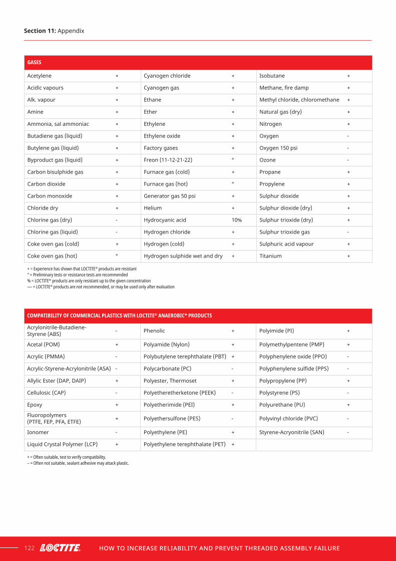
122 HOW TO INCREASE RELIABILITY AND PREVENT THREADED ASSEMBLY FAILURE
Section11: Appendix
GASES
Acetylene + Cyanogen chloride + Isobutane +
Acidic vapours + Cyanogen gas + Methane,firedamp +
Alk. vapour + Ethane + Methyl chloride, chloromethane +
Amine + Ether + Natural gas (dry) +
Ammonia, sal ammoniac + Ethylene + Nitrogen +
Butadiene gas (liquid) + Ethylene oxide + Oxygen -
Butylene gas (liquid) + Factory gases + Oxygen 150 psi -
Byproduct gas (liquid) + Freon (11-12-21-22) ° Ozone -
Carbon bisulphide gas + Furnace gas (cold) + Propane +
Carbon dioxide + Furnace gas (hot) ° Propylene +
Carbon monoxide + Generator gas 50 psi + Sulphur dioxide +
Chloride dry + Helium + Sulphur dioxide (dry) +
Chlorine gas (dry) - Hydrocyanic acid 10% Sulphur trioxide (dry) +
Chlorine gas (liquid) - Hydrogen chloride + Sulphur trioxide gas -
Coke oven gas (cold) + Hydrogen (cold) + Sulphuric acid vapour +
Coke oven gas (hot) ° Hydrogen sulphide wet and dry + Titanium +
+ = Experience has shown that LOCTITE® products are resistant ° = Preliminary tests or resistance tests are recommended % = LOCTITE® products are only resistant up to the given concentration — = LOCTITE® products are not recommended, or may be used only after evaluation
COMPATIBILITY OF COMMERCIAL PLASTICS WITH LOCTITE® ANAEROBIC* PRODUCTS
Acrylonitrile-Butadiene- Styrene (ABS) - Phenolic + Polyimide (PI) +
Acetal (POM) + Polyamide (Nylon) + Polymethylpentene (PMP) +
Acrylic (PMMA) - Polybutylene terephthalate (PBT) + Polyphenylene oxide (PPO) -
Acrylic-Styrene-Acrylonitrile (ASA) - Polycarbonate (PC) - Polyphenylenesulfide(PPS) -
Allylic Ester (DAP, DAIP) + Polyester, Thermoset + Polypropylene (PP) +
Cellulosic (CAP) - Polyetheretherketone (PEEK) - Polystyrene (PS) -
Epoxy + Polyetherimide (PEI) + Polyurethane (PU) +
Fluoropolymers (PTFE, FEP, PFA, ETFE) + Polyethersulfone (PES) - Polyvinyl chloride (PVC) -
Ionomer - Polyethylene (PE) + Styrene-Acryonitrile (SAN) -
Liquid Crystal Polymer (LCP) + Polyethylene terephthalate (PET) +
+ = Often suitable, test to verify compatibility. – = Often not suitable, sealant adhesive may attack plastic.

123
Unitconversiontable(imperial/metric)
DIMENSIONS LENGTH SI SYMBOL MULTIPLICITY ENGLISH OR C.G.S MULTIPLICITY TO GET SI OR C.G.S
Length metre m x 3.28 = feet x 0.305 = metre
millimetre mm x 0.039 = inch x 25.4 = millimetre
Force newton (kg•m/s2) n x 0.225 = pound x 4.448 = newton
kilogram kgf x 2.204 = pound (lbf avior) x 0.454 = kilogram
newton N x 3.597 = pound (lbf avior) x 0.287 = newton
Mass kilogram kg x 2.204 = pound (avior) x 0.454 = kilogram
Pressurestress megapascal Mpa (MN/m2) x 145 = lb-in2 x 0.00689 = megapascal
kgf/cm2 x 14.23 = lb-in2 x 0.0702 = kgf/cm2
daNcm2 x 14.5 = lb-in2 x 0.00689 = decanewton/cm2
Area sq.metre m2 x 10.8 = ft2 x 0.93 = megapascal
sq.centimetre2 cm2 x 0.155 = in2 x 6.45 = cm2
Torque newton metre N.m x 0.738 = lb-ft x 1.356 = newton metre
newton metre N.m x 8.85 = lb-in x 0.113 = newton metre
kgf.cm x 7.23 = lb-ft x 0.138 = kgf/m
kgf.cm x 0.87 = in-lb x 1.15 = kgf.cm
Volume cubic metre m3 x 0.001 = litre x 1000 = m3
litre (dm3) or m x 10-3 L x 1.057 = quart (liquid) x 0.946 = litre
litre (dm3) L x 33.81= ounce (us) x 0.02957 = litre
litre (dm3) L x 61.02 = in3 x 0.01639 = litre
cc (cm3) cc x 0.06102 = in3 x 16.39 = cc
Angle Radian rad x 57.30 = degree x 0.01745 = radian
Viscosity dynamic kinematic
pascal.sec sq.Metre/sec
Pa.s m2/s
x 1000 = x 10000 =
Centipoise Stokes
x 0.001 = x 0.0001=
= Pa.s = m2/s
11.3

11.5.1
124 HOW TO INCREASE RELIABILITY AND PREVENT THREADED ASSEMBLY FAILURE
Volumecalculation
Technicalinformation:Standardtestmethodsforthreadlockertesting
ISO 10964 adhesives Determinationthetorquestrengthofanaerobicadhesivesonthreadedfasteners:This ISO method is the most referenced method on a threadlocker technical data sheet. This method is used to determine the following cured properties ofthreadlockers:
• Break-away torque
• Break-loose torque
• Prevailing torque
• Heat aging
• Hot strength
• Chemical resistance
• Environmental resistance
11.4
11.5
Section11: Appendix
METRIC THREAD IMPERIAL THREAD VOLUME OF PRODDUCT PER COMPONENT* NUMBER OF COMPONENTS PER BOTTLE
(ML) 10 ml 50 ml 250 ml
M4 #8 0.006 1,600 8,000 40,000
M6 1/4" 0.018 500 2,500 12,500
M10 3/8" 0.060 160 800 4,000
M20 3/4" 0.454 20 100 500
M30 1-1/8" 0.995 10 50 250
* Assumes 0.1 mm clearance (M3–M10) and 0.2 mm clearance (M20 and M30), with 20% over application.

11.5.2
125
ISO 10123 adhesivesDetermining the shear strength of anaerobic adhesives using pin-and-collar specimens:Nutsandboltscanhavedimensionalvariationsintheirthreads. Those threads can also be damaged easily, leading to variations in the break-away and/or break-loose torque results. Hence, compressive shear strength is also evaluated to gain a more accurate characterization of a threadlocker product. Additionally, the pin-and-collar substrates used in this test have high tolerances and provide more reproducible results. This method is used to measure the followingcuredpropertiesofthreadlockers:
• Compressive shear strength
• Cure speed vs bond gap
SummaryofISO10123The standard specimen is comprised of a 12.65–12.675 mm (0.498–0.499") diameter pin and a slip collar with a 12.7–12.725 mm (0.500–0.501") inside diameterby11.05–11.15mm(0.435–0.439")wide.Bothcomponentsarefinishedto0.8–1.6μmRa(32–64μinRa)with0.025–0.075mm(0.001–0.003")diametralclearance between the pin and collar. The specimens are degreased before testing.
Theshearstrengthiscalculatedasfollows:
FIGURE 88 Pin and collar specimen.
wherebond area = π x pin diameter x collar width
shear strength = load at failure
bond area

11.5.3
126 HOW TO INCREASE RELIABILITY AND PREVENT THREADED ASSEMBLY FAILURE
ISO 16047 assemblyThe conditions for carrying out torque/clamp force tests on threaded fasteners andrelatedpartsarespecifiedinISO16047.Itisapplicable,basically,tobolts,screws, studs and nuts made of carbon steel and alloy steel, whose mechanical propertiesarespecifiedinISO898-1,ISO898-2orISO898-6andhaveISOmetricthreads with thread sizes M3 to M39. This method is used to measure the follow-ing uncured properties of a threaded assembly with and without threadlocker or other thread lubricants in order to provide a more accurate relationship between torqueandtension:
•Torquecoefficient(k-factor),K
•Coefficientofthreadfriction,μth
•Coefficientofbearingfriction,μb
•Coefficientoftotalfriction,μtot
Section11: Appendix
Henkel recommends that you test all new adhesive applications under simulated or actual end use conditions to ensure the adhesive meets or exceeds all required productspecifications.Sinceassemblyconditionsmaybecriticaltoadhesiveperformance, it is also recommended that testing be performed on specimens assembled under simulated or actual production conditions.

127

128 HOW TO INCREASE RELIABILITY AND PREVENT THREADED ASSEMBLY FAILURE
BIBLIOGRAPHYSection 12
“Adhesive.” Wikipedia. Wikimedia Foundation, August 30, 2020. https://en.wikipedia.org/wiki/Adhesive.
Bickford, John H. Introduction to the Design and Behavior of Bolted Joints: Non-Gasketed Joints.BocaRaton,FL,FL:CRCPress,2008.
Birkett, David, and David Condron. “Anaerobic Adhesives.” Henkel Adhesive Technologies, 2017. Birkett, David and David Condron. Anaerobic Adhesives.Whitestown,Dublin24,Ireland:HenkelAdhesiveTechnologies,Technology Centre Europe, 2017.
Degano, Ilaria, et al. Hafting of Middle Paleolithic tools in Latium (central Italy): New data from Fossellone and Sant’Agostino caves.Milano,Italy: PlosOne,2019.https://doi.org/10.1371/journal.pone.0213473.
European Committee for Standardization. “Adhesives - Terms and Definitions.” Adhesives: European Committee for Standardization, 2015.
Feeney, Michael. Reliable Threaded Fastener Assemblies: Torque-Tension Relationship- K Factor. Henkel Corporation, 2015.
Grant, Ellsworth S. Drop by Drop: the LOCTITE® Story. The LOCTITE® Corporation, 1983.

129
Haviland, Girard S. Machinery Adhesives for Locking, Retaining, and Sealing. NewYorkCity,NY:Dekker,1986.
Henkel. History, 2020, www.henkel.com/company/milestones-and-achievements/history.
Kerley, James J. An Application of Retroduction to Analyzing and Testing the Backing off of Nuts and Bolts during Dynamic Loading.Greenbelt,MD:GoddardSpace Flight Center, 1987.
Junker, Gerhard H. “New Criteria for Self-Loosening of Fasteners Under Vibration.” SAE Technical Paper Series,1969.https://doi.org/10.4271/690055.
“LOCTITE®.” Wikipedia. Wikimedia Foundation, January 2, 2020. https://en.wikipedia.org/wiki/Loctite.
Manufacturing Reliability Advanced Training Manual. 5th ed.RockyHill,CT: Henkel Corporation, 2005.
Olson, Tyler. Preload Influences on Fastener Fatigue Life.Winona,MN:FastenerTechnology International, 2015.
Pizzi, A., and K. L. Mittal. Handbook of Adhesive Technology.NewYorkCity,NY: M. Dekker, 2003.
“ShearThinning.”Wikipedia.WikimediaFoundation,July7,2020.https://en.wikipedia.org/wiki/Shear_thinning.
Speck, James A. Mechanical Fastening, Joining, and Assembly.BocaRaton,FL: Taylor & Francis, 2014.
“Thread-Locking Fluid.” Wikipedia. Wikimedia Foundation, January 1, 2020. https://en.wikipedia.org/wiki/Thread-locking_fluid.
Woo, Chulsoo. “Functional Adhesive Trend for Assembly Industry.” Henkel Corporation, 2018.
Woo, Chulsoo. “Liquid Thread Locking Solution for Assembly Industry.” Henkel Corporation, 2019.
Woo, Chulsoo. “Liquid Thread Locking Solution for Machinery Assembly Industry.” Adhesives and Adhesive Joints in Industry Applications, 2019. https://doi.org/10.5772/intechopen.85090.