How to extend Roberts' Law for eccentrically driven ... · Grashofs border cases for the inverted...
13
How to extend Roberts' Law for eccentrically driven, inverted slider-cranks Citation for published version (APA): Dijksman, E. A., & Smals, A. T. J. M. (1996). How to extend Roberts' Law for eccentrically driven, inverted slider- cranks. In J. Lenarcic, & V. Parenti-Castelli (Eds.), Recent advances in robot kinematics (pp. 325-336). Dordrecht: Kluwer Academic Publishers. Document status and date: Published: 01/01/1996 Document Version: Publisher’s PDF, also known as Version of Record (includes final page, issue and volume numbers) Please check the document version of this publication: • A submitted manuscript is the version of the article upon submission and before peer-review. There can be important differences between the submitted version and the official published version of record. People interested in the research are advised to contact the author for the final version of the publication, or visit the DOI to the publisher's website. • The final author version and the galley proof are versions of the publication after peer review. • The final published version features the final layout of the paper including the volume, issue and page numbers. Link to publication General rights Copyright and moral rights for the publications made accessible in the public portal are retained by the authors and/or other copyright owners and it is a condition of accessing publications that users recognise and abide by the legal requirements associated with these rights. • Users may download and print one copy of any publication from the public portal for the purpose of private study or research. • You may not further distribute the material or use it for any profit-making activity or commercial gain • You may freely distribute the URL identifying the publication in the public portal. If the publication is distributed under the terms of Article 25fa of the Dutch Copyright Act, indicated by the “Taverne” license above, please follow below link for the End User Agreement: www.tue.nl/taverne Take down policy If you believe that this document breaches copyright please contact us at: [email protected] providing details and we will investigate your claim. Download date: 15. Aug. 2019
Transcript of How to extend Roberts' Law for eccentrically driven ... · Grashofs border cases for the inverted...

How to extend Roberts' Law for eccentrically driven,inverted slider-cranksCitation for published version (APA):Dijksman, E. A., & Smals, A. T. J. M. (1996). How to extend Roberts' Law for eccentrically driven, inverted slider-cranks. In J. Lenarcic, & V. Parenti-Castelli (Eds.), Recent advances in robot kinematics (pp. 325-336).Dordrecht: Kluwer Academic Publishers.
Document status and date:Published: 01/01/1996
Document Version:Publisher’s PDF, also known as Version of Record (includes final page, issue and volume numbers)
Please check the document version of this publication:
• A submitted manuscript is the version of the article upon submission and before peer-review. There can beimportant differences between the submitted version and the official published version of record. Peopleinterested in the research are advised to contact the author for the final version of the publication, or visit theDOI to the publisher's website.• The final author version and the galley proof are versions of the publication after peer review.• The final published version features the final layout of the paper including the volume, issue and pagenumbers.Link to publication
General rightsCopyright and moral rights for the publications made accessible in the public portal are retained by the authors and/or other copyright ownersand it is a condition of accessing publications that users recognise and abide by the legal requirements associated with these rights.
• Users may download and print one copy of any publication from the public portal for the purpose of private study or research. • You may not further distribute the material or use it for any profit-making activity or commercial gain • You may freely distribute the URL identifying the publication in the public portal.
If the publication is distributed under the terms of Article 25fa of the Dutch Copyright Act, indicated by the “Taverne” license above, pleasefollow below link for the End User Agreement:
www.tue.nl/taverne
Take down policyIf you believe that this document breaches copyright please contact us at:
providing details and we will investigate your claim.
Download date: 15. Aug. 2019

HOW TO EXTEND ROBERTS' LAW FOR ECCENTRICALLYDRIVEN, INVERTED SLIDER-CRANKS
E.A.DIJKSMAN (author) & A.TJ.M.SMALS (software)Faculty o/Mechanical EngineeringEindhoven University o/Technology
The Netherlands
Abstract The extension of Roberts' Law concerns inverted slider-cranks with aneccentricity and a general tracing-point attached to the moving plane of the slider. Asboth curve-cognates degenerate in this case, the infinite turning-joint has first beenrep laced by a finite far-away joint, but such that the coupler-plane also meets twoaccuracy-positions of the erstwhile slider.One of the curve-cognates may then be adapted or modified until up to six accuracypositions are met. They seem to be sufficient to attain an extraordinary good approximation of the entire branch of the original curve. Besides, even the transmission-angle attainsa value about twice as large as the one obtained with the auxiliary four-bar representingthe first approximation.Cases, where the inverted slider-crank turns into a crank-and-rocker, into a double crankor even into a stretchable four-bar, are shown. The latter corresponds with one ofGrashofs border cases for the inverted slider-crank. Roberts' Law then ensures that eachinverted slider-crank, having a fully revolving crank, possesses three four-bar branchcognates this way.
l. Introduction
Though Roberts' Law (ref. [1]) describes the general existence of three four-bar curvecognates, all able to produce the same four-bar coupler curve, its application seems tocollapse when applied on a degenerated four-bar such as the inverted slider--crank.However, a previous paper [4] showed a practical circumvention in the special casewhere the inverted slider-cranks produced symmetrical curves. Then, a very goodapproximation was obtained based on stretch-rotation and symmetrization. However, forthe more general type of the (eccentric) inverted slider-crank, symmetrization isn'tapplicable and has to be replaced by another procedure, apparently leading to a similarconcurrence between the curves as in the symmetrical case.In the eccentric case, we are going to start from in this paper, also non-Grashof typesoccur. Then, there is no crank making a complete revolution, whereas the curve producedwill be singular branched as then only one branch occurs as the gradual merging result oftwo different branches originally produced by Grashoftypes.In the symmetrical case the replacement four-bar reproduced only one branch generatedby the then centrically driven inverted slider-crank. Naturally, something alike is to beexpected for the eccentric case. Thus, when an eccentrically driven inverted slider-crankis of the Grasfof-type, two branches appear, each possibly replaceable by one couplerbranch of a Grashof four-bar. For the Non-Grashof type only part of the curve may bereproduced. This part then corresponds with either a forward - or, otherwise, a backwardstroke of the "input-rocker" between its extreme positions (Fig. 9).
325
J. Lenari"h' and V. Parenti-Castelli (eds.), Recent Advances in Robot Kinematics. 325-336.© 1996 Kluwer Academic Publishers. Printed in the Netherlmuls.

d .. 8a"'e 1-----:----,e(.s 0< oI-l1(
/,"'//88 -0
326
-......"-
"-
",~ "
" / I \\( I I
-rtrl--L._-- I\ Ao / ,A", I J\ I / \
'-....~_/ \ /Ai \ /
" ./" ./'- ,/.............. .,/----
Fig. 1: Initial coupler branch produced by point K attached to the slider of an inverted slider
crank (4 accuracy positions chosen to design a 4-bar branch-cognate with)
\8/\\h\\\
\-'1,\..4,,,,
Fig. 2: Design of 4-bar branch cognate (nearly) producing the same coupler branch as the one
produced by the eccentric inverted slider-crank (4 position synthesis with position reduction)

327
2. Investigated Types
It is possible to distinguish between four types of eccentric inverted slider cranks. Two ofthem are of the Grashoftype, whereas two others are Non-Grashof. For the Grashof-type
either 11."1 < d (Fig. I), or d • "1 < II (Figrs.3, 10).
For the Non-Grashoftype, the crank-circle about A 0 has to intersect the eccentricity-circle
(about Bo) at real points Rand R , leading to the very existence of ~ AoRBo meeting
the three Non-Grashof conditions:
d < "1 • II
Of these, the last one has to be met anyway, otherwise no real mechanism is to be drawn
with real tangents to the eccentricity-circle. Thus, as "/ < II + d represents an almost
trivial condition, true also for Grashof linkages, only two cases are left for the NonGrashof type. They are:
case Icase II
d - "/ < II < d' (Fig. 9)d < II < d. "1
Note that for the centric case, for which e l = 0, the Non-Grashof types disappear.Further, border-cases appear when either II • "1 • d (Fig. 6) or d·"l· II .
Of course, in order to be complete, all occurring cases are of interest when looking forthe possible existence of four-bar branch cognates when Grashof linkages are at hand, or"haJf curve cognates" when Non-Grashof inverted slider cranks are presented (Fig. 9).
3. Design of the 4-bar braoch-cognate
The actual design of the four-bar cognate replacing the inverted slider-crank occurs intwo stages: (Figrs. 2, 4, 7, (9) and 10)In the 151 stage a first approximation is adopted leading to an auxiliary four-bar, based ontwo specifically chosen accuracy positions of the coupler-point and on a simultaneousreplacement of the slider.In the 2nd stage, part of Roberts' Configuration is used to find another crank-circle,simultaneously giving the designer the opportwlity to improve his first approximation ofthe branch through two other pairs of specifically chosen accuracy positions.As a result, only one branch of the 4-bar coupler curve approximates the chosen branch,initially produced by the inverted slider-crank. For the other branch one finds anotherbranch-cognate somewhat different from the first.Accuracy positions, as will be proved, occur in pairs. That is to say, for each accuracyposition another exists leading to the same result. So, basically, the design uses only threeaccuracy positions, in reality being six.The first pair is to be allocated for the auxiliary four-bar, whereas the remaining pairs areto be used for the final mechanism found in the 2 nd stage.

328
Fig. 3: Original coupler-branch produced by a coupler point K of an inverted slider-crank with
eccentricity e, (4 accuracy positions are used to obtain the 4-bar branch cognate)
+-Ja,. 4<--' ":'!fR'at • .$,"11"
a' - G,&4U'- iI(~OIJ/{J• A.,n°
6'· 1/,S61J¥c'• ..cP, !lOS
'." J~
Fig. 4: The ecc. inverted slider-crank as well as the double crank. (being
the branch cognate) producing the same coupler branch

329
3.1 THE AUXILIARY FOUR-BAR
In order to simplify matters and to attain a unified method for all cases, the first pair ofaccuracy-positions are taken to correspond with the perpendicular positions of the inputcrank with respect to the frame. (Figrs. 1, 3, 6, 10). Then, P 12 ' the virtual rotation centerof the positions, A 1K I and A2K2, coincides at the center B°of the eccentricity-circle. (Themid-normal ofB tB2- always joins Bo.)One further replaces the slider A IR1, touching the eccentricity-circle at R I , by a basicallyrequired large "circle" with center B I' Then, the last point, becoming a finite turningjoint, has to comply with the first two accuracy-positions, whence B I joins the nonnal ofA1K I , simultaneously meeting point P 12 = Bo.
In order to have a large length for c· Bll• • h + 81 (1)
one chooses the angle II = <{ BIAIR1= 80°. (In case 11= 90° , one reattains the invertedslider-crank.)The dimensions of the auxiliary mechanism (A o-AIK1BI-Bo) having the same crank, thesame coupler-point, and also the same center - Bo- as the inverted slider-crank we started
from, is then to be established from the initiaJ dimensions: AIJ• • d; ArA.· II ;
BeRl • 8 1 ; AICI· P and 8 J ,the latter being the shortest distance from K I to AIRI·
We so find that:
- ..; J J JA,RI· d • II - til
AlBI • b • A~I COS,I U
(2)
(3)
(4)
(5)
(6)<l: KllrAl • P • arcstn{!!. stn(u - arcstn2 )]q p
Clearly, the design of the auxiliary mechanism is the same for all Grashof-types having afuJly revolving crank. Thus,
for II ~ d - til with d> til (Figrs. 1, 6)
for II ::t d • Ifl with d> til (Fig. 3)
and for II ::t d • 81 with d < til (Fig. ]0)
Of course, as II < 90° , the curve produced by the auxiliary mechanism will deviate a bitfrom the initial curve as produced by the eccentric inverted slider-crank. However, thedeviation is to be corrected by application of the 2 od stage leading to the final replacementmechanism.

330
/,' -IIG,IJINJ
,. -.!M,ISI
ai' - .s~g,..
, _ GG,S'J!
I,' -115;804.C'_ I.I/, .t1lS"
.(A-__
Ctk/~/
/'
/'I
fI
( ~4t------~---?_-=:::::::::::::::::::::::::.--.II\\\\\'\
'\'\'\'\
""",.......... k ",/
....... _--..+!_---""
Fig. 5: The double crank as a four-bar branch cognate ofan eccentrically driven inverted slider
crank: (the 2 mechanisms produce about the same branch with nearly the same input velocity)
B~~ .&rrJ,rC_
Two IJrancAH A1It(Yn.J gl"~
Fig. 6: Eccentrically driven, inverted slider crank: (4 accuracy positions
to be used for the design of a 4-bar branch cognate)
331
3.2 FINAL FOUR-BAR BRANCH COGNATE
Naturally, further enlargement of the angle II leads to lower values for the transmissionangle III = <{ BoBIAI' (For instance, if II = 90°, then III = 0°)As this is undesired with regard to force-transmission, other ways have to be found.Whence, we abide by II = 80° , but look at Roberts' Law and ditto Configuration instead.Though Roberts' Law may then be applied caused by the now finite location of point B I'
the transformation does not change the curve itse'lf.However, if we consider a particular curve-cognate of Roberts', namely the one having acran k rotating with the same speed as the angular velocity of the initial crank, it becomesfeasible to change three of its cognate-dimensions, in order to meet three different accuracy positions. To carry this out in detail, the following procedure is adopted:I. First, change the auxiliary four-bar into its Roberts'curve-cognate having
a crank Ao"A" rotating with the same speed as the initial crank A oA,
2. Secondly, replace turning-joint (B;j..... or (B;j..... until B" meets the
three (or six) accuracy-positions being chosen.
In more detai I, this would lead to the stretch-rotation of b. A1AoBo about Bo with the
complex multiplication-factor !J...IP, yieldingb
b. A 'A'B • !l t1lp(b. A A R'1 0 0 b ,"O""'lV
For the 2 nd accuracy-position, a similar equation holds:
Hence, we so obtain the simple formulas:
A--;B: . d' • !ldb
A',.' , qInO • a • -ab
Further, <{ BaA;A;'· 900• - <( BaA;A;'
Whereas, similarly according to Roberts' Configuration, also
(7)
(8)
(9)
(10)
(II)
(I 2)
Naturally, the perpendicular bisectors of A;'A; and of K/C2 intersect at Bo. Thus,
yielding B01 • Bo • B02
(I3)
(I 4)
Then, with two other chosen accuracy positions from the initially given mechanism, sayA)K) and A4K4, it becomes quite possible to determine accurate corresponding positions,
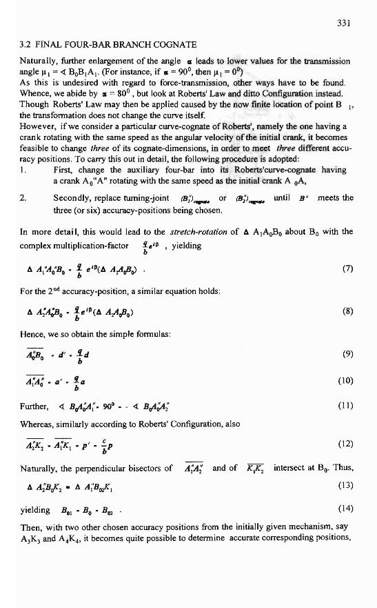
f'g. 7, l)eS'" a[ [a"'-"'" """,'b-Ca..'" a[ ",ve<1£d'Ii""'"""'"
("""hOr, Ba'''''' _ a • " • d ",,,l,,,g \0 o· • b' > d' H' )

333
Al' and A~' , at the cognated crank-circle about A~'. This may be realized by
intersection of circles having radius p' respectively about K 3 and K 4, with the
cognated crank-circle about A"()
When, for instance, A 3 as well as A4 join the initial fixed link A oBo , we find that both,
A; as well as A~' , slightly deviates from the line containing the cognated fixed link,
that is to say from A/:Jl() . Anyway, having determined their exact locations at the
cognated crank-circle, we may establish the locations of the points, B(IJ and BH . The
way to find these points, will be based on the so-called attachment-method, hence, on the
equations:
(15)
(16)
The circle joining the three points BOI = B02 ' B03 and B04 then has the required tuming
joint B; for its center.
As a result, one obtains the new dimensions:
(17)
In the particular case for which the initial branch is symmetrical, which occurs when the
two eccentricities are zero, B;' coincides at the center of a circle joining K 1 , Bo and
A;' . In that case b'. c' • q' , meaning that the four-bar is of the ~-type (ref.[4]).
The accuracy-positions chosen, corresponded with the initial crank-positions dividing36Qo into equal parts of90 o.
A measure for the accuracy of the cognate curve may be found by comparing theGrashof-distances of the two mechanisms. Then, the best approximation will be the onehaving its Grashof-distance-ratio much nearer the value I than with other approximations. For the mechanisms of Fig. 2, for instance, the auxiliary four-bar yields the
Grashof-distance-ratio a • c - d - b • 1.57 , whereas the final branch-cognate resultsa - d • SJ
into the ratio d(a' • b' - c' - d') • 0.914. Thus, the latter represents the better mechad'(a - d • s,)
nism. (Note that the Grashof-distance-ratio equals 1 when two Roberts' 4-bar curvecognates are compared.)
For the auxiliary mechanism of Fig. 4, we obtain the Grashof-distance-ratio

334
At1(4·n·-d!./r,)-Ia-dHJ• .e,N-:!-/~-:d.40; il • .wJ; III-S0;~ • .ss-;' A,b -V","/,o"" 1r ~ I /
~1KW~_d-tY ;""4I1d ..c.A . /..;,"'''~K·\ .... ')1 AD
\ "-
"
' ....................,
' ....----_.Fig. 9: Non-GrashofCurve-Cognate
--- --...... c....~.... .(
.... ...."
"-\
\\\\\\\I
~K.t
-$ I .-11I1, If}-.r, .~-
,.V~~-",.;~ •.eAI,f,
A.~t...",; ~-A;f.l'M"k
t: -A'II,; ,-V.4"¥/I-W• ~si4f1Rr«).IO·
tI'·fd.S fll··III.'"/ • .t~. ~JW
• .J".~~C·-..eI,M
l_M,~
Fig. 10: Iverted slider crank and its 4-bar branch-cognate producing the same branch(4 position-synthesis using a point position reduction method: B01 = B01)

d • c - a - b • 2.34a - d - el
335
whereas the branch-cognate gives rise to the ratio
d(d' • b' - a' - c') • 0.81.
d'(a - d - el)
Even for Non-Grashof linkages, namely for those without revolving bars, the methodremains applicable. Fig. 9, for instance, yields for the auxiliary mechanism the Grashof-
distance-ratio a· b - c - d • 1.65 ,whereas the final curve-cognate gives the ratioa - d. el
d(a' • c' - d' - b').=....!..=----=.--=--~• 1.35.
d'(a - d • el)
It is quite possible that an other distribution of our accuracy-positions, gives a betterGrashof-ratio. Remarkable better results though, are not to be expected. For instance, ifwe choose point A 4 of Fig. 9 at the other intersection of the crank - and the eccentricity-
circle, we obtain the ratio d(a'. c' - d' - h') • 0.73. Now, its distance to 1 is onlyd'(a- d. "1)
slightly less than with the 1.35-vaJue belonging to the mechanism demonstrated in Fig. 9.In Grashofs border case, such as the particular one demonstrated in the Figrs. 6 and 7, werather observe the differeru:e between these Grashof-distances.Then, for the auxiliary mechanism we precisely observe the value
(a • c - h- d) - (a • lJ1 - d) • Jd2 • a 2 - 6 12 (sinll - 1)C()6-1« •
• - 40..[3 tan~[(n/2) - II] • - 40..[3 tan sD • - 6.0614
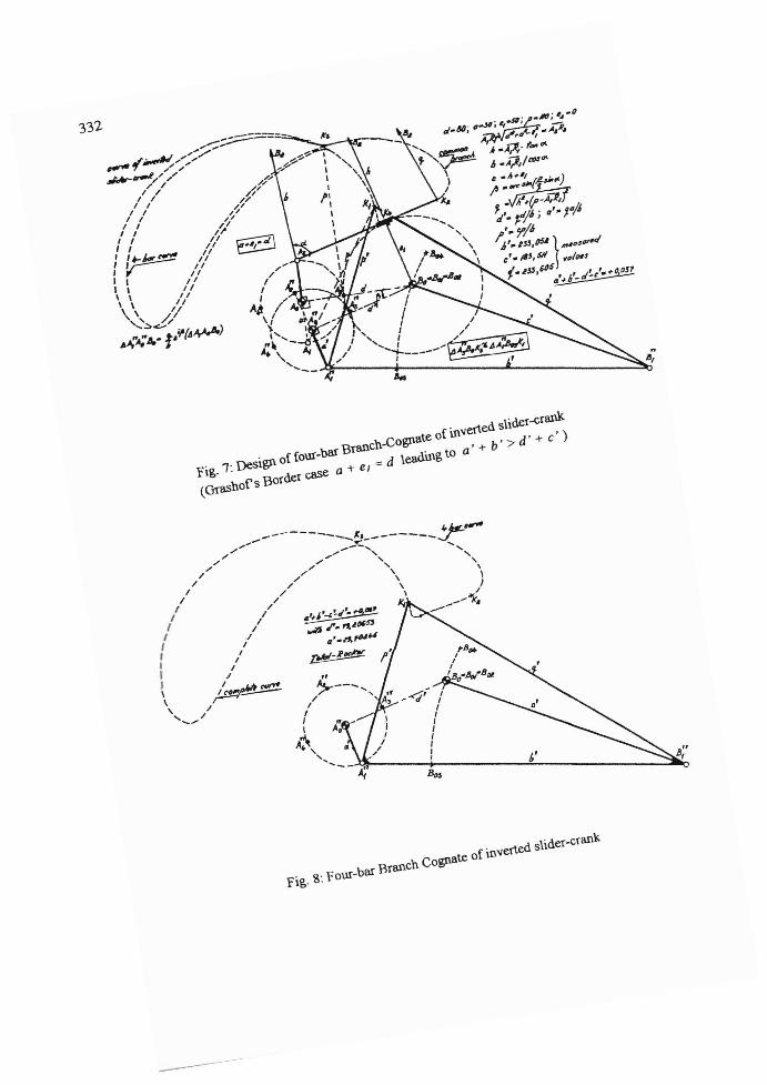
As in this case each Grashof-distance should tend to zero, a considerable improvement isobtained with the final branch-cognate as demonstrated in Fig. 8. Then, namely
.!!.. . (a' • h' - C I - d') - (a • _, - d) •• 0.037 .d'
A random circle about Bo intersecting the cognated crank-circle at possible accuracy
positions A~ and A~' ,yields a virtual rotation-centre P om = Bo , giving BOrn = BOn.Indeed, accuracy-positions only occur in pairs. Thus, each accuracy-position has to becounted twice, unless of course the cognated crank-positions already are at a circle about
Bo, as will be the case for the accuracy-positions, A;' and A;' .
Generally, the transmission angle ~ I = « A;'BiE, appears to be about twice as large as
the one obtained with the auxiliary four-bar or with its Roberts' curve-cognate. Complete
application of Roberts' Law would have lead to a point (B;') as the fourth vertex of,..,...a linkage parallelogram BIJ~I(Bi'),..,... . However, such a point (B;'J,..,... would have
been much farther away, giving about half the transmission-angle. All examples demonstrated show this same phenomenon. We conclude, that the 2 nd stage leads to a better
approxima tion of the generated branch, simultaneously giving about twice the transmission angle in comparision to the one obtained in the 1 sl stage.

336
Theoretically, the circular curve described by point B 0 of the Stephenson-2 six-bar
(.40 - A - B- - Bo - A; - At - K1) with respect to the link AtK\ will be a
Stephenson-2 six-bar curve of order 16, (ref.[5J). Clearly, this curve approximates a
circle very neatly, although in reality not more than 16 intersections exist. (yoIe count 2times 16, minus the (8 times 2) intersections of the circle at the two circular or isotropic
points of the curve.)
4. Conclusions
Branches of CUIVes produced by inverted slider-cranks having an eccentricity and/or aneccentrically located coupler point, are to be reproduced by even three different four-barbranch-cogn ates. In the two cases the curves are singular branched, the three four-barCUIVe- cognates reproduce only part of the CUIVe, namely the part corresponding to eithera forward - or, otherwise a backward stroke of the input-rocker. Better transmissionangles may be attained at the cost of the accuracy of the reproduction. In most casesthough a high accuracy is obtained with acceptable transmission angles. (The accuracy ofthe replacement-method has been measured with a newly introduced Grashof-distanceratio.)
References
I. Roberts, S. (1875) Three-bar motion in plane space, Proc.London Math.Soc. 7,pp.14-23
2. Stoimenov, M., Panteli eo T. (1979) Possibility of the development of a curved translationand for a member of an extended kinematic chain of a curved sliding mechanism,Proc. ofthe 5 rlr World Congress on the Theory ofMachines and Mechanisms,pp 1436-1439. published by the ASME.
3. Dijksman, E.A. (1976) Motion Geometry of Mechanisms, (Chapter 5: Cognate Linkages),ambridge niversiry Pr s.
1981) CinemAtica De Mecanismos. (Cap.5: Mecanismos Cognados)Editorial L1MUSA, SA., Mexico
4. Dijksman, E.A. (1996) How to exchange centric inverted slider cranks with ).,-fonned fourbar linkages, Mechanism and Machine Theory (in press)
5. Primrose, E.J.F., Freudenstein, F., Roth, B. (1967) Six-Bar Motion II The Stephenson-land Stephenson-2 Mechanisms, Archive for Rational Mechanics and Analysis.Volume 24,Nr.l, pp.55-72.