How Mockups, a Key Engineering Tool, Help to Promote ... · Science, Technology, Engineering, and...
20
NASA USRP – Internship Final Report How Mockups, a Key Engineering Tool, Help to Promote Science, Technology, Engineering, and Mathematics Education Harry E. McDonald IV 1 NASA Undergraduate Student Research Program Intern, Houston, Texas 77058 The United States ranking among the world in science, technology, engineering, and mathematics (STEM) education is decreasing. To counteract this problem NASA has made it part of its mission to promote STEM education among the nation’s youth. Mockups can serve as a great tool when promoting STEM education in America. The Orion Cockpit Working Group has created a new program called Students Shaping America’s Next Space Craft (SSANS) to outfit the Medium Fidelity Orion Mockup. SSANS will challenge the students to come up with unique designs to represent the flight design hardware. There are two main types of project packages created by SSANS, those for high school students and those for university students. The high school projects will challenge wood shop, metal shop and pre-engineering classes. The university projects are created mainly for senior design projects and will require the students to perform finite element analysis. These projects will also challenge the undergraduate students in material selection and safety requirements. The SSANS program will help NASA in its mission to promote STEM education, and will help to shape our nations youth into the next generation of STEM leaders. Nomenclature STEM = Science, Technology, Engineering, and Mathematics PE = Participatory Exploration CEV = Crew Exploration Vehicle LFM = Low Fidelity Mockup MFM = Medium Fidelity Mockup CAD = Computer Aided Design SAA = Space Act Agreement PDR = Preliminary Design Review CDR = Critical Design Review CAR = Customer Acceptance Review HUNCH = High Schools United with NASA to Create Hardware SSANS = Students Shaping America’s Next Spacecraft IGES = Initial Graphics Exchange Specification T-STEM = Texas Science, Technology, Engineering and Mathematics I. Introduction n recent years the United States of America, historically known to be a leader in innovation and science, has been falling behind. In a study of 15 year-old students around the world the U.S. ranked 28th in math literacy and 24th in science literacy as well as 20 th in college graduates in natural science and engineering. 12 To counter act these falling numbers the U.S. government and grass roots originations have made a large push in science, technology, engineering and mathematics (STEM) education for the nation’s youth. President Obama is taking a progressive approach towards STEM education by making a goal for American students to go from the middle of the pack to the top in science and math achievements over the next decade. 1 ____________________________ 1 Fall USRP Intern, EA3 Systems Architecture and Integration, NASA JSC, Kansas State University I https://ntrs.nasa.gov/search.jsp?R=20100042409 2018-07-16T12:40:54+00:00Z
Transcript of How Mockups, a Key Engineering Tool, Help to Promote ... · Science, Technology, Engineering, and...
NASA USRP – Internship Final Report
How Mockups, a Key Engineering Tool, Help to Promote
Science, Technology, Engineering, and Mathematics
Education
Harry E. McDonald IV1
NASA Undergraduate Student Research Program Intern, Houston, Texas 77058
The United States ranking among the world in science, technology, engineering, and
mathematics (STEM) education is decreasing. To counteract this problem NASA has made
it part of its mission to promote STEM education among the nation’s youth. Mockups can
serve as a great tool when promoting STEM education in America. The Orion Cockpit
Working Group has created a new program called Students Shaping America’s Next Space
Craft (SSANS) to outfit the Medium Fidelity Orion Mockup. SSANS will challenge the
students to come up with unique designs to represent the flight design hardware. There are
two main types of project packages created by SSANS, those for high school students and
those for university students. The high school projects will challenge wood shop, metal shop
and pre-engineering classes. The university projects are created mainly for senior design
projects and will require the students to perform finite element analysis. These projects will
also challenge the undergraduate students in material selection and safety requirements.
The SSANS program will help NASA in its mission to promote STEM education, and will
help to shape our nations youth into the next generation of STEM leaders.
Nomenclature
STEM = Science, Technology, Engineering, and Mathematics
PE = Participatory Exploration
CEV = Crew Exploration Vehicle
LFM = Low Fidelity Mockup
MFM = Medium Fidelity Mockup
CAD = Computer Aided Design
SAA = Space Act Agreement
PDR = Preliminary Design Review
CDR = Critical Design Review
CAR = Customer Acceptance Review
HUNCH = High Schools United with NASA to Create Hardware
SSANS = Students Shaping America’s Next Spacecraft
IGES = Initial Graphics Exchange Specification
T-STEM = Texas Science, Technology, Engineering and Mathematics
I. Introduction
n recent years the United States of America, historically known to be a leader in innovation and science, has
been falling behind. In a study of 15 year-old students around the world the U.S. ranked 28th in math literacy
and 24th in science literacy as well as 20th
in college graduates in natural science and engineering.12
To counter
act these falling numbers the U.S. government and grass roots originations have made a large push in science,
technology, engineering and mathematics (STEM) education for the nation’s youth. President Obama is taking a
progressive approach towards STEM education by making a goal for American students to go from the middle of
the pack to the top in science and math achievements over the next decade.1
____________________________ 1Fall USRP Intern, EA3 Systems Architecture and Integration, NASA JSC, Kansas State University
I
https://ntrs.nasa.gov/search.jsp?R=20100042409 2018-07-16T12:40:54+00:00Z

NASA USRP – Internship Final Report
Johnson Space Center 12/06/2010 2
“Reaffirming and strengthening America’s role as the world’s engine of scientific discovery and technological
innovation is essential to meeting the challenges of this century,” said President Obama. “That’s why I am
committed to making the improvement of STEM education over the next decade a national priority.”1
NASA is at the center of technological and scientific achievements in America and the world. NASA needs
sharp young minds to continue to be a leader in innovation. Because of the falling numbers in America’s
educational system NASA has started to increase its efforts in educational outreach and STEM education.
NASA is composed primarily of scientists and engineers. With the baby boomer generation on the verge of
mass retirement, NASA needs to continue to bring in STEM majors to sustain its workforce and attained knowledge.
To make sure NASA can still recruit from the best and brightest NASA has developed three main educational
goals:2
Strengthening NASA and the Nation’s future workforce
Attracting and retaining students in science, technology, engineering and mathematics, or STEM
disciplines
Engaging Americans in NASA’s mission
Along with these goals, NASA has created the office of Participatory Exploration (PE). PE is described as an active
involvement of individuals in NASA’s research and exploration.3 This office has been created to allow for a more
interactive approach between the public and NASA. PE allows the public to go beyond participating in outreach
programs, and creates a mechanism for the public to be a contributing member to a project without being a
government employee. PE can assist NASA in its educational goals by encouraging youth as well as adults to
pursue STEM activities in efforts to help NASA in innovation and exploration.
II. Human in the loop evaluations Mock-ups have been used at NASA in the design of spacecraft and hardware since the Gemini program. Four
main objectives mockups help to accomplish are design development, human in the loop testing for flight design
verification, astronaut training, and education of the public about the various NASA programs. Currently, the main
focuses of the Orion mockups are human in the loop verification tests. Human in the loop tests are used to evaluate
human interfaces in the Crew Exploration Vehicle (CEV). Tests include all astronaut activities that need to occur
inside the spacecraft such as ingress into the CEV, egress out of the CEV, and interaction with the vehicle displays,
controls and various equipment. Tests are done by NASA focusing on human interfaces both in a gravity
environment and on orbit in weightlessness. Two mockups that will aid NASA in this objective are called the Low
Fidelity Mockup (LFM) and the Medium Fidelity Mockup (MFM).
The fidelity of the hardware is based on Table 1 and following definitions from Ref. 4.
Table 1. Fidelity Classification Matrix4
Functional Class
A.
Functionally
Active
B.
Operable
C.
Static
Flight assembly tolerance
Similar materials
Exact configuration
IA
IB
IC
Relaxed assembly tolerance
(+0.25”)
Mixed materials
Approximate configuration
IIA
IIB
IIC
Approximate dimensions (+0.50”)
Optional materials
Appropriate configuration
IIIA
IIIB
IIIC
A. DEFINITIONS
Functionally Active - The capability of functionally replicating the stimuli, processes and/or responses of the
original article. The mockup article shall respond in a manner simulating the original (e.g., a light fixture shall light
when the switch is toggled, or hand controller or keypad input invokes a physical response to the evaluator).
Operable - The capability of functionally replicating the general movement of the original article without a response
to the evaluator (e.g., a light fixture does not light when the switch is toggled but the light and switch are present , or
hand controller / keypad is physically present and moveable, but does not invoke a simulated response).

NASA USRP – Internship Final Report
Johnson Space Center 12/06/2010 3
Static - No active stimuli, processes or responses to the evaluator (e.g., photographic or volumetric representations
of light, switches, hand controllers etc.).
Class I: Flight Assembly Tolerance – Conforms to flight (or ground) article dimensions.
Similar Materials – Materials are of the same family and characteristics as the flight article, but are
not necessarily the same grade.
Exact Configuration – Appearance is like flight article in all aspects.
Class II: Relaxed Assembly Tolerance – Not held to flight specifications; margins defined by requirements
document.
Mixed Materials – Materials meet general characteristics of flight article and optimally support the
intended function, but need not be of the same family, grade or specification.
Approximate Configuration – Appearance is similar to flight article (size, shape, color, orientation,
location, etc.).
Class III: Approximate Dimensions - Not held to flight dimensions; greater tolerance given to dimensions as
specified in requirements document.
Optional Materials – No restrictions on material selection provided the end item meets the
requirements.
Appropriate Configuration – Appearance to depict the design or anticipated concept.
The LFM is mainly composed of volumetric hardware mockups in the IIC to IIIC category, with a few articles
in the IIB category. A low fidelity hardware mockup is usually constructed out of foam board, or other inexpensive
and easy to use construction materials. The LFM is useful for initial design assessments as well as human factors in
layout of the hardware inside the crew cabin. As flight models of the hardware inside the cabin change, the LFM
allows for rapid prototyping, installation and assessment.
The MFM currently is comprised only of a IIB fidelity shell of the CEV. Currently the budget for outfitting the
MFM is minimal, and most work by NASA employees and contractors is on hold. This mockup will consist of
much higher fidelity hardware ranging from IB to IIC fidelity. The MFM will be used for the final stages of design
development similar to efforts that have been done in LFM, but will have more dimensionally correct human
interfaces and hardware locations. In addition, the MFM will provide the fidelity needed to conduct final spacecraft
verification of a number of human focused vehicle requirements that must be formally verified before the spacecraft
will be approved for flight.
III. Mockups relating to STEM
Mockups can be great tools for increasing STEM education and interest in the students today. They can be
directly accessed by students, allowing for the mockups to be a hands on learning tool. Mockups can be seen
everywhere from miniature buildings to full scale International Space Station layouts. They have been a great tool
when informing the public about complex hardware designs. Because mockups are not space flight hardware,
students can help to design and construct the hardware inside the mockup with little engineering background.
Requirements for the mockup hardware can be created that help to further the student’s education in STEM and
hopefully increase their interest in the subject as well. The Orion Cockpit Working Group currently uses interns to
update the LFM to the latest flight design, and is kicking off an effort to have university and high school students
outfit the MFM.
NASA USRP – Internship Final Report
Johnson Space Center 12/06/2010 4
A. Construction of Low Fidelity Hardware
The main objective of an intern working on the LFM and MFM is to update the hardware installed on forward
bulkhead and the barrel walls according to the latest flight computer aided design (CAD) model. This is done
through the following steps:
1. Obtain the latest flight CAD model
2. Obtain the latest excel database of flight hardware assemblies and parts
3. Reference old flight models to verify what parts are to me installed in the crew cabin
4. Search the database for the part number or part name that is to be updated
5. Pull up the part model in ProEngineer (ProE) for dimensioning
6. Update or Create a forward bulkhead view in the flight model to accurately depict where the hardware is
located
7. Construct the hardware to volumetric representation of the flight design
8. Install hardware within 0.5 inches of the flight hardware location
Volumetric representation gives interns room for creativity when constructing the mockup hardware. Decals
are heavily used in the LFM to give the user an understanding of the complicated structures as well as approximate
location of switches, knobs and connectors. The fidelity of most of the hardware is currently in the process of being
updated from IIC to IIB. Because of the budget, the crew systems flight hardware design development is mostly on
hold, which provides a unique opportunity for the fidelity of the hardware to increase due to a stable design.
The main obstacle when installing hardware is what to reference measurements from. If the intern measures
from previously installed hardware major error can occur due to an error in the placement of the referenced
hardware. To overcome this problem lines have been drawn on the mockup that represent the Y and Z planes in the
flight model. Distance and angle measurements can be taken from these planes to accurately place the mockup
hardware.
B. Outfitting the Medium Fidelity Mockup
Budget pressures have limited the ability to outfit the MFM by NASA employees. Due to these pressures, the
Cockpit Working Group has created an educational outreach program called Students Shaping America’s Next
Spacecraft (SSANS). SSANS will incorporate high schools, community colleges, vocational schools and universities
to outfit the MFM. The wide range of project requirements is the driving force behind involving so many levels of
education. The project packages are developed to challenge the students in the design and fabrication of the
hardware, and to guide them in the engineering design process. SSANS is taking the course of action to team up
with existing programs as well as developing new partnerships. The main legal agreement that needs to be in place
for NASA to interface with a school is a Space Act Agreement (SAA).
The SAA is designed to clearly define the roles and limitations of NASA and the schools so that ultimately the
final product can be used by NASA. A draft SAA for SSANS is attached in Appendix A. The SAA highlights the
requirements from NASA such as providing a mentor, providing agreed upon materials necessary for the project,
and outlining how the project packages are constructed. The SAA also outlines such things as intellectual property
rights, the ability of NASA to have multiple partners in outfitting the mockup, and liability issues. It is
recommended that the NASA legal department co-author the SAA with the program members. New Space Act
Agreements are only needed when there is no preexisting agreement between NASA and the associated partner.
C. Partnering with Existing Programs
There are a few programs already formed that have allowed the SSANS program to rapidly move forward with
project package delivery. The three main programs that SSANS is looking to partnering with are High School
Students United with NASA to Create Hardware (HUNCH), Texas STEM (T-STEM) centers and the Texas Design
Challenge (TDC).
1. High School Students United with NASA to Create Hardware
HUNCH was started in 2003 by a JSC engineer.6 HUNCH has the ability to manufacture as high as IB fidelity
mock-up hardware for drastically lower prices than NASA would pay for contract work. NASA supplies the
material, mentoring and JSC tours, whereas the high school provides the student design and construction labor along
with the tools necessary for construction. An example of what HUNCH schools can accomplish is highlighted on
NASA.gov when students at Clear Creek High School manufactured space station training lockers that would have
cost NASA as much as $10,000 to manufacture.5 HUNCH schools around the Houston area are able to work with
metal, wood, plastics, and fabrics. For the initial projects SSANS program members will meet with each potential
school to assess the schools capabilities for SSANS projects. For future projects an application will be used and the

NASA USRP – Internship Final Report
Johnson Space Center 12/06/2010 5
schools will apply for the SSANS projects. HUNCH can be a great tool to stream line mock-up hardware
fabrication. HUNCH has SAAs established with many local schools in the Houston, Texas area, which will allow
for projects to be started as early as December 2010.
2. Texas Science Technology Engineering Mathematics Centers
T-STEM centers, like HUNCH, have a direct relationship with high schools and vocational schools that meet
SSANS requirements for MFM outfitting projects. SSANS is looking to partner with the following T-STEM
centers: University of Texas Medical Branch T-STEM, Texas Tech University T-STEM and the University of Texas
Tyler T-STEM. The mission of the T-STEM centers is highlighted on the official T-STEM website. “The Texas Science, Technology, Engineering and Mathematics Centers address the challenges of tomorrow’s
technology-driven economy by researching, developing, and supporting best practices in science, technology,
engineering, and mathematics education for K-12 schools.”7
T-STEM centers are focusing their efforts to counteract the decreasing technical competency in America’s
students. They promote and develop projects such as SSANS as well as develop curriculum that encourages and
pushes students to become more technically minded. SAA agreements have not previously been drafted for T-
STEM schools SSANS is looking to partner with. An example draft of the SAA for one of the centers is attached in
Appendix A.
3. University Partnering
Projects that require finite element analysis and experience in various engineering disciplines will be given to
universities. Universities will either be hand selected for new partnerships or be a part of an existing program like
the Texas Design Challenge. When partnering with a university SSANS mentors will hold regular meetings with
the design team to mentor them on the design challenges of the SSANS project. The projects developed for this
package will be created as if the work was given to a contractor, and the mentors will hold the student team
responsible for meeting all the safety and design requirements.
4. Texas Space Grant Consortium Texas Design Challenge
The Texas Design Challenge is sponsored by the Texas Space Grant Consortium (TSGC). This program allows
university students around the state of Texas to participate in mission relevant engineering design problems.8 NASA
mentors submit a design problem to TSGC and TSGC helps NASA to interface with the universities and develop
project requirements. TSGC has an extensive amount of project guidelines listed on its website
www.tsgc.utexas.edu/challenge. The SSANS program will potentially submit multiple university projects to TSGC.
Using the design challenge as the mechanism for the university projects benefits SSANS because the guidelines and
instructions for mentors and students have already been developed, SAAs already exist, and the professors are
familiar with NASA design projects. Funding for the projects comes from TSGC, which benefits SSANS due to a
small budget.
D. Creating Student Projects
There is a wide variety of student projects for outfitting the MFM. The SSANS program is looking for IIB to
IIC level of fidelity in the hardware depending on the project type and educational level of students. There are two
main project categories, high school related projects and university related projects. High school projects include
the smaller or less-complex pieces of non-load-bearing hardware. The requirements for these projects focus on the
hardware visual appearance and do not require significant materials or engineering knowledge. University projects
require much more understanding in the areas of material selection, stress analysis, and the engineering design
process. When creating packages, attention is given to the student’s educational level so that the students can have
design challenges suited for that level. For all the projects a project outline will be given to the school detailing the
project guidelines and requirements. An example of a project outline is given in Appendix B. Included with the
project outline will be either drawings or CAD models that the students will base their hardware designs from.
1. High School Projects
High school projects are aimed at students enrolled in machine shop, wood shop, pre-engineering or home
economics classes. They will consist of hardware to be mounted on the forward bulk head and interior walls of the
CEV. The project package will outline all the requirements that SSANS sets for the project. For SSANS projects
there will be a requirement of three design reviews, which include the preliminary design review (PDR), critical
design review (CDR) and a customer acceptance review (CAR). The package will outline what is needed for each
design review. The following is an example of what the project outline would include about the PDR from the

NASA USRP – Internship Final Report
Johnson Space Center 12/06/2010 6
Auxiliary Bus Control Unit project.9
PRELIMINARY DESIGN REVIEW (PDR)
A PDR shall be conducted to ensure that the proposed design concepts comply with the
requirements. The PDR shall, at a minimum, consist of a review of the following:
a. Engineering design
b. Structural analysis plan
c. Design concepts for functional / semi-functional components
d. Fabrication plan and drawing tree / list
e. Mockup Installation Concept
f. Hazard List – Hazards to personnel using the ABCU mockup once installed in the Orion
mockup
Electronic copies of all material to be presented at the PDR shall be submitted to NASA five
working days prior to the scheduled PDR. PDR drawings shall depict approximately 80 percent of
all materials and parts to a 30 percent level of detail. The preliminary structural analysis shall
include; structural geometry, member sizes, load conditions, support conditions and trainer
weights, and shall be ready for review 5 days prior to the PDR.
Students must use the engineering design process to understand the requirements and develop the hardware
design as well as a plan for implementing the hardware in the MFM. Safety is a large part of the requirements that
will challenge the students to come up with unique designs. SSANS mentors will work with the high schools
extensively to make sure they are on the right track when constructing the project hardware. If the dimensional
fidelity is lowered, schools should give reasons in their PDR. Students have the freedom to be creative in their
redesigning of the flight model. For hardware that is to be installed on the forward bulkhead students must provide
high level information regarding structural analysis. The students must also provide information about how the
hardware will be supported and able to interface with humans without causing a safety hazard such as falling off.
2. University Projects
The packages of this type either directly support the weight of the human user, or are heavy enough that
constructing and mounting them is a major design challenge. These projects are proposed for upper level design
courses in universities. Stress Analysis will need to be done using the finite element method to show that material
selection, mounting hardware, and modified flight design are strong enough to hold the specified load in the
package. The project outline document will be set up in the same manner as the high school projects but with more
advanced requirements to challenge the undergraduate engineering design team. CAD models will be given to show
the dimensions that the group must adhere to. Most hardware will still be required to meet fidelity IIB and IIC
standards; however, because of the advanced knowledge of the design teams some additional hardware will be
required to include fidelity of IIA, providing flight-like hardware.
3. Creating Computer Aided Design Models
CAD models will be used whenever possible. The more practice students have with CAD the better experience
they have in the engineering design process. Students can use the CAD model to pull the desired design dimensions
as well as get a better understanding of what the flight hardware looks like. Based on the CAD model students will
either create their own CAD models or drawings of their hardware design. They will then use these models to
present at design reviews as well as reference the drawings when constructing the mockup hardware.
When creating CAD models, pictures, and drawings for the project packages, protection of sensitive
information must be addressed. The CAD models and drawings must give the minimal amount of detail about the
hardware and the overall design of the CEV due to ownership of the model by Lockheed Martin, and because space
flight is a national security issue. Therefore, only the most needed dimensions can go out in the packages.
All the hardware in the ProE flight model references other parts. To overcome the problems of referencing and
sensitive data the flight hardware models are shrinkwrapped. Shrinkwrapping in ProE saves the models surfaces,
but does not save how the model was constructed. This eliminates much of the sensitive material about the
hardware, and makes it possible to send out in project packages. The shrinkwrapped part is then saved as an Initial
Graphics Exchange Specification (IGES) file. An IGES file is a common readable file among all CAD software.

NASA USRP – Internship Final Report
Johnson Space Center 12/06/2010 7
6"
6"
6½"
3"
3½"
3"
2" 1½"
1½"
Figure 1. Contingency Gas Analyzer Dimensions
9
Figure2. Positive
Pressure Relief Valve
Figure3. Lighting
Power Module
Figure4. Lighting Power
Module
IV. Results for SSANS
SSANS is still in its infancy. Preliminary project packages are planned to go out to select schools in early
December 2010. Initial project packages have been developed for the HUNCH program. These will help the
mentors evaluate their developed requirements for high school students as well as educate themselves on what is
needed for the high school students to be successful.
There have been a total of 17 project packages created, all relating to high school projects. Figure 1, below, is
an example of what the high school students will use as a reference when constructing their hardware.
A power point outline has also been created for the students to document their work. The groups will use this
document in the design reviews and other project presentations. It will also serve as a standard form that will be
easy to understand for the engineers of SSANS. The following list is an outline of all the main topics covered in the
power point.
Project Schedule
Requirements outline
Initial Design
How the team plans to meet requirements
Proof showing that the requirements were met
with approved design
Final Design and Fabrication Outline
Fabrication
Acceptance Testing
During discussions among the various possible
partners of the SSANS program a project description
outline was created. This document served as the
initial introduction to the various programs about the
possible projects. It outlines all the major projects
explaining high-level project requirements, and shows
overview pictures of what the students will be doing.
This document will be used further when entering into partnerships with new schools and programs.
V. Results in the Construction of Low Fidelity Hardware
The following is an example of an intern’s accomplishments during a 15 week tour in the fall of 2010.
A. Internship Example from Fall 2010 I have updated the LFM’s forward bulkhead to the latest flight model. For this objective I used a wide range of
fidelity when constructing
the hardware. Figure 2, 3,
and 4, to the right, help to
explain the different levels of
fidelity incorporated in the
LFM. The speaker unit is a
mixture of IB and IIB
fidelity and the positive
pressure relief valve is an
example of IIC fidelity. The
speaker unit will be installed
in the MFM and will be an
example for the SSANS
student projects. Table 2,
shown on the next page, lists the hardware I have updated as well as the level of fidelity it is currently in.

NASA USRP – Internship Final Report
Johnson Space Center 12/06/2010 8
Table 2. Completed Hardware
Hardware Fidelity Level
Speaker Unit IB, IIB
Power Equipment Panel IIC
Audio control Speaker Unit IIC
Snorkel Fan IIC
Zone ½ Lighting Power Module IIB
Positive Pressure Relief Valve IIC
Cabin Return Diffuser IIC
Docking Light IIB, IIC
VI. Conclusion
Construction of mockup hardware can be a very useful tool for NASA to promote STEM education. The
projects that students work on help them to advance in technical subjects, and would promote NASA to the next
generation. The projects stimulate the student’s minds technically because of the design problems of material
selection, accurate volumetric representation, and safety requirements. The SSNAS mockup projects will become a
vital part of NASA’s path to a successful new Orion spacecraft, allowing students to take pride in their work and
pride in NASA itself.
During the process of construction students will have access to NASA engineers. This can be a great
resource for the students to ask questions about engineering, the project they are working on, and about NASA in
general. The engineers can help to guide the students toward STEM degrees by helping them get excited about
engineering and science. NASA’s mission towards education is of high importance, and involving engineers in this
mission is key towards raising interest in STEM related majors.
Internships can be a great way to get students interested in NASA and its wide range of projects. By
including students in NASA programs, they can go back to their various communities and promote STEM by
presenting about the projects they worked on. NASA’s outreach in states that do not have a NASA center is limited.
Interns can help to expand this outreach when they go back to communities where there is no center. Internships
also help to shape students into successful engineers. By including students in engineering projects early, NASA is
speeding up the learning curve of young engineers allowing them to be ready to take on greater challenges when
stepping into the work force. John F. Kennedy once said, “Our progress as a nation can be no swifter than our
progress in education. The human mind is our fundamental resource.”10,11
This statement helps to sum up why
NASA’s number one priority should be to promote STEM education. Without achievement in America’s student
population then NASA, a leader in innovation, will cease to exist.
NASA USRP – Internship Final Report
Johnson Space Center 12/06/2010 9
Appendix A.
NONREIMBURSABLE SPACE ACT AGREEMENT
BETWEEN
NASA
AND
THE UNIVERSITY TEXAS MEDICAL BRANCH AT GALVESTON
FOR AND ON BEHALF OF
THE SOUTHEAST REGIONAL T-STEM CENTER14
ARTICLE 1. AUTHORITY AND PARTIES
In accordance with The National Aeronautics and Space Act of 1958, as amended (42 U.S.C. 2473(c)), this
Agreement is entered into by and between the NASA Lyndon B. Johnson Space Center located at 2101 NASA
Parkway, Houston, TX 77058 (hereinafter referred to as “NASA JSC”, “JSC”, or “NASA”) and The University of
Texas Medical Branch at Galveston, located at 301 University Boulevard, Galveston, TX 77555 (hereinafter
referred to as “UTMB” or “Partner”), for and on behalf of its Southeast Regional T-STEM Center (hereinafter
referred to as “SRT-STEM Center”). NASA and Partner may be individually referred to as a “Party” and
collectively referred to as the “Parties.”
ARTICLE 2. PURPOSE
NASA JSC will enter into a Space Act Agreement with Partner and the SRT-STEM Center in order to pursue the
“Students Shaping America's Next Spacecraft” Program currently being managed at UTMB. The SRT-STEM
Center facilitates collaboration between colleges, high schools and other institutions (“SRT-STEM Participants”) to
bring real-world engineering projects into the classroom to foster interest and skill development in the areas of
science, technology, engineering, and mathematics (“STEM”). In the first phase of this project, NASA will partner
with the SRT-STEM Center to allow students to design and fabricate Orion Medium Fidelity Mock-up (MFM)
components and participate in other relevant educational projects with guidance and mentoring from experienced
NASA engineers. Through this partnership, the SRT-STEM Center will fulfill its mandate to provide an interesting,
challenging real-world education experience to its affiliated schools. This partnership will allow Johnson Space
Center to further advance its outreach objectives and STEM education ideals. It will also allow for further
dissemination of information about the unique nature of NASA development hardware and space craft design
evaluations into academia.
ARTICLE 3. RESPONSIBILITIES
A. UTMB and the SRT-STEM Center will use reasonable efforts to:
1. Serve as an intermediary between NASA JSC and SRT-STEM Participants;
2. Manage the preliminary selection and matching of all schools/classes/students with projects;
3. Coordinate necessary telecommunications tools and/or travel for selected SRT-STEM
Participants;
4. Provide NASA with CAD models, electronic presentation materials and relevant analysis as
applicable for each project;
5. Participate in formal design reviews for each project;
6. Participate in hardware acceptance review (if applicable) for each project;
7. Participate in project meetings as necessary; and
8. Help coordinate shipping of finished projects to NASA by the SRT-STEM Participants.
B. NASA will use reasonable efforts to:
1. Provide detailed flight vehicle component drawings, mock-up component requirements, and other
information to define the use and design trade space for each project;
2. Provide informal mentoring as required to clarify requirements and project parameters;

NASA USRP – Internship Final Report
Johnson Space Center 12/06/2010 10
3. Support formal design reviews with the SRT-STEM Participants;
4. Conduct an early conceptual design review to ensure students meet intents of project requirements,
and provide results of this review to UTMB;
5. Conduct a final design review to ensure students meet requirements before fabrication, and
provide results of this review to UTMB;
6. Provide agreed upon materials to UTMB or SRT-STEM Participants (as appropriate) for
fabrication of mock-up hardware as necessary;
7. Conduct an acceptance review of all design and analysis data as well as any fabricated hardware;
8. Provide documentation of acceptance criteria of student-developed hardware;
9. Conduct other project reviews as necessary; and
10. Arrange for shipping of all agreed upon materials necessary for project performance to UTMB or
SRT-STEM Participants (as appropriate).
ARTICLE 4. SCHEDULE AND MILESTONES
The approximate planned major milestones for the activities defined in Article 3 above are as follows:
1. NASA and SRT-STEM Center will have a preliminary Q&A to refine
project requirements.
Approximately one week after team
selections
2. NASA and SRT-STEM Center will agree upon project materials and
shipment requirements.
Approximately four weeks after
team selections
3. NASA will acknowledge acceptance of SRT-STEM Center material
requests related to the projects.
Approximately five weeks after
team selections
4. SRT-STEM Center will provide NASA with all relevant CAD models,
presentation material, pertinent analysis, and fabricated mock-up
hardware as applicable for each project.
Approximately two weeks prior to
project completion
5. SRT-STEM Center will coordinate shipment of all completed projects
to NASA.
Approximately two weeks prior to
project completion
6. SRT-STEM Center will coordinate with NASA JSC to hold bi-monthly
project meetings, when deemed necessary by both parties.
Approximately bi-monthly
7. NASA and SRT-STEM Center will coordinate a final design review. Approximately three weeks prior to
project completion
ARTICLE 5. FINANCIAL OBLIGATIONS
There will be no transfer of funds or other financial obligations between the Parties under this Agreement and each
Party will fund its own participation and be responsible for its own costs incident to this Agreement. All activities
under or pursuant to this Agreement are subject to the availability of funds, and no provision of this Agreement shall
be interpreted to require obligation or payment of funds in violation of the Anti-Deficiency Act, Title 31 U.S.C. §
1341.
ARTICLE 6. PRIORITY OF USE
Any schedule or milestone in this Agreement is estimated based upon the Parties’ current understanding of the
projected availability of NASA personnel, facilities and equipment. In the event that NASA’s projected availability
changes, Partner shall be given reasonable notice of that change, so that the schedule and milestones may be
adjusted accordingly. The Parties agree that NASA usage of its facilities, equipment, and personnel shall have
priority over the usage planned in this Agreement. Should a conflict arise, NASA in its sole discretion shall
determine whether to exercise that priority. Likewise, should a conflict arise as between two commercial users,
NASA, in its sole discretion, shall determine the priority as between the two users. This Agreement does not

NASA USRP – Internship Final Report
Johnson Space Center 12/06/2010 11
obligate NASA to seek alternative government property or services under the jurisdiction of NASA at other
locations.
ARTICLE 7. NONEXCLUSIVITY
This Agreement is not exclusive; accordingly, NASA may enter into similar Agreements for the same or similar
purpose with other U.S. private or public entities.
ARTICLE 8. LIABILITY AND RISK OF LOSS
1. To the extent permitted by law, each Party hereby waives any claim against the other Party, employees of
the other Party, the other Party’s contractors and subcontractors at any tier, grantees, investigators,
customers, users, and their contractors or subcontractors at any tier (collectively referred to herein as
“Related Entities”), or employees of the other Party’s Related Entities for any injury to, or death of, the
waiving Party’s employees or the employees of its Related Entities, or for damage to, or loss of, the
waiving Party’s property or the property of its Related Entities arising from or related to activities
conducted under this Agreement, whether such injury, death, damage, or loss arises through negligence or
otherwise, except in the case of willful misconduct.
2. To the extent permitted by law, each Party further agrees to extend this cross-waiver to its Related Entities
by requiring them, by contract or otherwise, to waive all claims against the other Party, Related Entities of
the other Party, and employees of the other Party or of its Related Entities for injury, death, damage, or loss
arising from or related to activities conducted under this Agreement. Additionally, each Party shall require
that their Related Entities extend this cross-waiver to their Related Entities by requiring them, by contract
or otherwise, to waive all claims against the other Party, Related Entities of the other Party, and employees
of the other Party or of its Related Entities for injury, death, damage, or loss arising from or related to
activities conducted under this Agreement.
ARTICLE 9. INTELLECTUAL PROPERTY RIGHTS - DATA RIGHTS
1. General
(a) “Related Entity” as used in this Article 9, means a contractor, subcontractor, grantee, or other
entity having a legal relationship with NASA or Partner that is assigned, tasked, or contracted with
to perform specified NASA or Partner activities under this Agreement.
(b) “Data” as used in this Article 9, means recorded information, regardless of form, the media on
which it may be recorded, or the method of recording. The term includes, but is not limited to,
data of a scientific or technical nature, computer software and documentation thereof, and data
comprising commercial and financial information.
(c) “Proprietary Data” as used in this Article 9, means Data embodying trade secrets developed at
private expense or comprising commercial or financial information that is privileged or
confidential, and is marked with a suitable restrictive notice, provided that such Data is not known
or available from other sources without obligations concerning its confidentiality; has not been
made available by the owners to others without obligation concerning its confidentiality; is not
already available to the Government without obligation concerning its confidentiality; has not
been developed independently by persons who have had no access to the information; and, is not
required to be disclosed pursuant to Federal statute, law, regulation, or valid court order.
(d) The Data rights set forth herein are applicable to employees of Partner and employees of any
Related Entity of Partner. Partner shall ensure that its employees and employees of any Related
Entity that perform Partner activities under this Agreement are aware of the obligations under this
clause and that all such employees are bound to such obligations.
NASA USRP – Internship Final Report
Johnson Space Center 12/06/2010 12
(e) Data exchanged between NASA and Partner under this Agreement will be exchanged without
restriction as to its disclosure, use, or duplication except as otherwise provided in this Agreement.
(f) No preexisting Proprietary Data will be exchanged between the Parties under this Agreement
unless specifically authorized in this Agreement or in writing by the owner of the Proprietary
Data.
(g) In the event that Data exchanged between NASA and Partner includes a restrictive notice that
NASA or Partner deems to be ambiguous or unauthorized, NASA or Partner may notify the other
Party of such condition. Notwithstanding such a notification, as long as the restrictive notice
provides an indication that a restriction on use or disclosure was intended, the Party receiving such
Data will treat the Data pursuant to the requirements of this Article 9 unless otherwise directed in
writing by the Party providing such Data.
2. Data First Produced by Partner Under this Agreement
In the event Data first produced by Partner (or any Related Entity of Partner) in carrying out Partner
responsibilities under this Agreement is furnished to NASA, and Partner considers such Data to be
Proprietary Data, and such Data is identified with a suitable restrictive notice, NASA will use reasonable
efforts to maintain the Data in confidence and such Data will be disclosed and used by or on behalf of the
U.S. Government (under suitable protective conditions) for U.S. Government purposes only.
3. Data First Produced by NASA Under this Agreement
Except for data disclosing an invention owned by NASA for which patent protection is being considered, in
the event Partner requests that Data first produced by NASA (or any Related Entity of NASA) in carrying
out NASA’s responsibilities under this Agreement be maintained in confidence, and to the extent NASA
determines that such Data would be Proprietary Data if it had been obtained from Partner, NASA will mark
such Data with a restrictive notice and will use reasonable efforts to maintain such marked Data in
confidence for a period of [insert a period of up to 5 years, typically 1 or 2 years] after development of the
Data, with the express understanding that during the aforesaid restricted period such marked Data may be
disclosed and used (under suitable protective conditions) by or on behalf of the U.S. Government for U.S.
Government purposes only, and thereafter for any purpose whatsoever without restriction on disclosure and
use to the extent permitted by law. Partner agrees not to disclose such marked Data to any third party
without NASA’s written approval until the aforesaid restricted period expires.
4. Publication of Results
Recognizing that Section 203 of the National Aeronautics and Space Act of 1958 (42 U.S.C. § 2473), as
amended, requires NASA to provide for the widest practicable and appropriate dissemination of
information concerning its activities and the results thereof, and that the dissemination of the results of
NASA activities is one of the considerations for this Agreement, the Parties agree to coordinate proposed
publication of results with each other in a manner that allows each Party a reasonable amount of time to
review and comment on proposed publications.
5. Data Disclosing an Invention
In the event Data exchanged between NASA and Partner discloses an invention for which patent protection
is being considered, the furnishing Party specifically identifies such Data, and the disclosure and use of
such Data is not otherwise limited or restricted herein, the receiving Party agrees to withhold such Data
from public disclosure for a reasonable time (presumed to be 1 year unless mutually agreed otherwise or
unless such information is restricted for a longer period herein) in order for patent protection to be
obtained.
6. Copyright
NASA USRP – Internship Final Report
Johnson Space Center 12/06/2010 13
In the event Data is exchanged with a notice indicating that the Data is copyrighted and there is no
indication that such Data is subject to restriction under paragraphs 2 or 3 of this Article 9 (i.e., Data is not
marked with a restrictive notice as required by paragraphs 2 or 3 of this Article 9), such Data will be
presumed to be published and the following royalty-free licenses will apply:
(a) If it is indicated on the Data that the Data existed prior to, or was produced outside of, this
Agreement, the receiving Party and others acting on its behalf, may reproduce, distribute, and
prepare derivative works only for carrying out the receiving Party’s responsibilities under this
Agreement.
(b) If the Data does not contain the indication of subparagraph (a) above, the Data will be presumed to
have been first produced under this Agreement and, except as otherwise provided in paragraph 5
of this Article 9 and in Article 10 of this Agreement for protection of reported inventions, the
receiving Party and others acting on its behalf may reproduce, distribute, and prepare derivative
works for any purpose.
7. Data Subject to Export Control
Technical data, whether or not specifically identified or marked, that is subject to the export laws and
regulations of the United States and that is provided to Partner under this Agreement will be treated as
such, and will not be further provided to any foreign persons or transmitted outside the United States
without proper U.S. Government authorization, where required.
ARTICLE 10. INTELLECTUAL PROPERTY RIGHTS - INVENTION AND PATENT RIGHTS
1. The invention and patent rights set forth herein are applicable to any employees, contractors,
subcontractors, or other entities having a legal relationship with Partner that are assigned, tasked, or
contracted with to perform specified Partner activities under this Agreement. Partner agrees to inform such
employees, contractors, subcontractors, or other entities of the obligations under this Agreement and to
bind them to such obligations.
2. Based on the purpose and scope of this Agreement, and the responsibilities of the Parties, NASA has made
an administrative determination that the provisions of Section 305(a) of the National Aeronautics and
Space Act of 1958, as amended (42 U.S.C. § 2457(a)), do not apply to this Agreement. Therefore, title to
inventions made (conceived or first actually reduced to practice) as a result of activities performed under
this Agreement will remain with the respective SRT-STEM Participants, students or inventing party(ies), as
appropriate. No invention or patent rights are exchanged between or granted by such parties under this
Agreement except that NASA and Partner agree to use reasonable efforts to identify and report to each
other any invention that is believed to have been made jointly by employees of Partner and employees of
NASA (including employees of such NASA contractors, subcontractors, or other entities), and to consult
and agree as to the responsibilities and course of action to be taken to establish and maintain patent
protection on such invention and on the terms and conditions of any license or other rights to be exchanged
or granted by or between NASA and Partner.
ARTICLE 11. USE OF NASA NAME AND NASA EMBLEMS AND RELEASE OF GENERAL INFORMATION
TO THE PUBLIC
1. NASA Name and Initials
Partner agrees the words “National Aeronautics and Space Administration” and the letters “NASA” will
not be used in connection with a product or service in a manner reasonably calculated to convey any
impression that such product or service has the authorization, support, sponsorship, or endorsement of
NASA, which does not, in fact, exist. In addition, with the exception of release of general information in
accordance with paragraph 3 below, Partner agrees that any proposed public use of the NASA name or
initials (including press releases resulting from activities conducted under this Agreement and all
promotional and advertising use) shall be submitted by Partner in advance to the NASA Assistant

NASA USRP – Internship Final Report
Johnson Space Center 12/06/2010 14
Administrator for Public Affairs or designee (“NASA Public Affairs”) for review and approval. Approval
by NASA Public Affairs shall be based on applicable law and policy governing the use of the NASA name
and initials.
2. NASA Emblems
Use of NASA emblems/devices (i.e., NASA Seal, NASA Insignia, NASA logotype, NASA Program
Identifiers, and the NASA Flag) are governed by 14 CFR Part 1221. Partner agrees that any proposed use
of such emblems/devices shall be submitted to NASA Public Affairs for review and approval in accordance
with such regulations.
3. Release of General Information to the Public
NASA or Partner may, consistent with state or Federal law and this Agreement, release general information
regarding its own participation in this Agreement as appropriate.
ARTICLE 12. DISCLAIMER OF WARRANTY
Equipment, facilities, technical information, and services provided by NASA under this Agreement are provided “as
is.” NASA makes no express or implied warranty as to the condition of such equipment, facilities, technical
information, or services, or as to the condition of any research or information generated under this Agreement, or as
to any products made or developed under or as a result of this Agreement, including as a result of the use of
information generated hereunder, or as to the merchantability or fitness for a particular purpose of such research,
information, or resulting product, or that the equipment, facilities, technical information, or services provided will
accomplish the intended results or are safe for any purpose, including the intended purpose, or that any of the above
will not interfere with privately owned rights of others. Neither the Government nor its contractors shall be liable
for special, consequential or incidental damages attributed to such equipment, facilities, technical information, or
services provided under this Agreement or such research, information, or resulting products made or developed
under or as a result of this Agreement.
ARTICLE 13. DISCLAIMER OF ENDORSEMENT
NASA does not endorse or sponsor any commercial product, service, or activity. NASA’s participation in this
Agreement or supply of equipment, facilities, technical information, or services under this Agreement does not
constitute endorsement by NASA. Partner agrees that nothing in this Agreement will be construed to imply that
NASA authorizes, supports, endorses, or sponsors any product or service of Partner resulting from activities
conducted under this Agreement, regardless of the fact that such product or service may employ NASA-developed
technology.
ARTICLE 14. COMPLIANCE WITH LAWS AND REGULATIONS
The Parties shall comply with all applicable laws and regulations including, but not limited to, safety, security,
export control, and environmental laws and regulations. Access by Partner to NASA facilities or property, or to a
NASA Information Technology (IT) system or application, is contingent upon compliance with NASA security and
safety policies and guidelines including, but not limited to, standards on badging, credentials, and facility and IT
system/application access.
With respect to any export control requirements:
(a) The Parties will comply with all U.S. export control laws and regulations, including the
International Traffic in Arms Regulations (ITAR), 22 CFR Parts 120 through 130, and the Export
Administration Regulations (EAR), 15 CFR Parts 730 through 799, in performing work under this
Agreement. In the absence of available license exemptions/exceptions, Partner shall be
responsible for obtaining the appropriate licenses or other approvals, if required, for exports of
hardware, technical data and software, or for the provision of technical assistance.

NASA USRP – Internship Final Report
Johnson Space Center 12/06/2010 15
(b) Partner shall be responsible for obtaining export licenses, if required, before utilizing foreign
persons in the performance of work under this Agreement, including instances where the work is
to be performed on-site at NASA and where the foreign person will have access to export-
controlled technical data or software.
(c) Partner will be responsible for all regulatory record keeping requirements associated with the use
of licenses and license exemptions or exceptions.
(d) Partner will be responsible for ensuring that the provisions of this Article 14 apply to its Related
Entities.
ARTICLE 15. TERM OF AGREEMENT
This Agreement becomes effective upon the date of the last signature below and shall remain in effect until the
completion of all obligations of both Parties hereto, or three (3) years from the date of the last signature, whichever
comes first.
ARTICLE 16. RIGHT TO TERMINATE
Either Party may unilaterally terminate this Agreement by providing thirty (30) calendar days written notice to the
other Party.
ARTICLE 17. CONTINUING OBLIGATIONS
The rights and obligations of the Parties that, by their nature, would continue beyond the expiration or termination of
this Agreement, e.g., “Liability and Risk of Loss” and “Intellectual Property Rights” shall survive such expiration or
termination of this Agreement.
ARTICLE 18. MANAGEMENT POINTS OF CONTACTS
The following personnel are designated as the principal points of contact between the Parties in the performance of
this Agreement.
Technical Points of Contact:
NASA Lyndon B. Johnson Space Center
Paul Marshall
Orion Project Office
Mail Stop: ZV
2101 NASA Parkway
Houston, TX 77058
Phone: 281-483-0682
SRT-STEM Center
UTMB
Clifford W. Houston, Ph.D.
301 University Boulevard
Mail Route 0981
Galveston, TX 77555
ARTICLE 19. DISPUTE RESOLUTION
Except as otherwise provided in Article 6 entitled “Priority of Use,” Article 10 entitled “Intellectual Property Rights
– Invention and Patent Rights” (for those activities governed by 37 CFR Part 404), and those situations where a pre-
existing statutory or regulatory system exists (e.g., under the Freedom of Information Act, 5 U.S.C. § 552), all
disputes concerning questions of fact or law arising under this Agreement shall be referred by the claimant in
writing to the appropriate person identified in this Agreement as the “Management Points of Contact.” The persons
identified as the “Management Points of Contact” for NASA and the Partner will consult and attempt to resolve all
issues arising from the implementation of this Agreement. If they are unable to come to agreement on any issue, the
dispute will be referred to the signatories to this Agreement, or their designees, for joint resolution. If the Parties
remain unable to resolve the dispute, then the NASA signatory or that person’s designee, as applicable will issue a
written decision that will be the final agency decision for the purpose of judicial review. Nothing in this section

NASA USRP – Internship Final Report
Johnson Space Center 12/06/2010 16
limits or prevents either Party from pursuing any other right or remedy available by law upon the issuance of the
final agency decision.
ARTICLE 20. MODIFICATIONS
Any modification to this Agreement shall be executed, in writing, and signed by an authorized representative of
NASA and Partner. Any modification that creates an additional commitment of NASA or Partner resources must be
signed by the original NASA or Partner signatory authority, or successor, or a higher level NASA or Partner official
possessing original or delegated authority to make such a commitment.
ARTICLE 21. ASSIGNMENT
Neither this Agreement nor any interest arising under it will be assigned by Partner or NASA without the express
written consent of the officials executing this Agreement.
ARTICLE 22. APPLICABLE LAW
U.S. Federal law and the laws of the State of Texas govern this Agreement for all purposes, including, but not
limited to, determining the validity of the Agreement, the meaning of its provisions, and the rights, obligations and
remedies of the Parties.
ARTICLE 23. INDEPENDENT RELATIONSHIP
This Agreement is not intended to constitute, create, give effect or otherwise recognize a joint venture, partnership,
or formal business organization, or agency agreement of any kind, and the rights and obligations of the Parties shall
be only those expressly set forth herein.
ARTICLE 24. SIGNATORY AUTHORITY
The signatories to this Agreement covenant and warrant that they have authority to execute this Agreement. By
signing below, the undersigned agree to the above terms and conditions.
NATIONAL AERONAUTICS AND SPACE
ADMINISTRATION
LYNDON B. JOHNSON SPACE CENTER
THE UNIVERSITY OF TEXAS MEDICAL
BRANCH AT GALVESTON, for and on behalf of the
SOUTHEAST REGIONAL
T-STEM CENTER
BY:___________________________
Doug Cooke
Associate Administrator
BY:___________________________
William R. Elger, CPA
Executive Vice President and Chief
Business and Finance Officer
DATE:_________________________
DATE:_________________________
__________
Content Reviewed

NASA USRP – Internship Final Report
Johnson Space Center 12/06/2010 17
Appendix B.
Auxiliary Bus Control Unit (ABCU) Project Package13
High Level Project Task: Design, build, and deliver hardware simulating the Orion Auxiliary Bus Control Unit (ABCU). Details and
requirements for this task are contained in this document.
ABCU Background Concepts of Operations
The Auxiliary Bus Control Unit (ABCU) is a switch panel mounted on the forward bulkhead (overhead) that
controls power distribution to displays and controls on the main console. It also provides power and control to
various equipment used for post-landing operations or emergency situations, when main electrical power to the
vehicle is shut down.
ABCU front panel layout
The ABCU is normally only reconfigured just after the spacecraft reaches orbit and transitions from ascent
to orbit mode and again at the end of the mission prior to deorbit to transition from orbit to entry mode. The crew
must get out of the seats to reconfigure the panel, because it is out of reach when they are strapped in for ascent and
entry.
The ABCU panel utilizes switches and LEDs to provide control and feedback on the power status of the
applicable equipment. Each switch controls a remote power controller (RPC), a solid state power control and circuit
protection device. Each RPC is instrumented with On/Off status and a Trip status that indicates if an electrical short
has occurred which has automatically interrupted the circuit. Each switch and LED is labeled according to
standardized nomenclature, font, color, and size rules to ensure both readability and minimization of errors in
operation.
NASA USRP – Internship Final Report
Johnson Space Center 12/06/2010 18
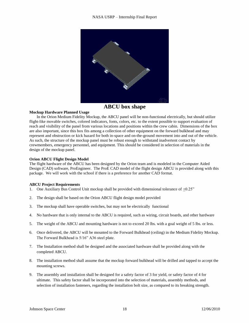
ABCU box shape
Mockup Hardware Planned Usage
In the Orion Medium Fidelity Mockup, the ABCU panel will be non-functional electrically, but should utilize
flight-like movable switches, colored indicators, fonts, colors, etc. to the extent possible to support evaluation of
reach and visibility of the panel from various locations and positions within the crew cabin. Dimensions of the box
are also important, since this box fits among a collection of other equipment on the forward bulkhead and may
represent and obstruction or kick hazard for both in-space and on-the-ground movement into and out of the vehicle.
As such, the structure of the mockup panel must be robust enough to withstand inadvertent contact by
crewmembers, emergency personnel, and equipment. This should be considered in selection of materials in the
design of the mockup panel.
Orion ABCU Flight Design Model
The flight hardware of the ABCU has been designed by the Orion team and is modeled in the Computer Aided
Design (CAD) software, ProEngineer. The ProE CAD model of the flight design ABCU is provided along with this
package. We will work with the school if there is a preference for another CAD format.
ABCU Project Requirements
1. One Auxiliary Bus Control Unit mockup shall be provided with dimensional tolerance of +0.25”
2. The design shall be based on the Orion ABCU flight design model provided
3. The mockup shall have operable switches, but may not be electrically functional
4. No hardware that is only internal to the ABCU is required, such as wiring, circuit boards, and other hardware
5. The weight of the ABCU and mounting hardware is not to exceed 20 lbs. with a goal weight of 5 lbs. or less.
6. Once delivered, the ABCU will be mounted to the Forward Bulkhead (ceiling) in the Medium Fidelity Mockup.
The Forward Bulkhead is 5/16” A36 steel plate.
7. The Installation method shall be designed and the associated hardware shall be provided along with the
completed ABCU.
8. The installation method shall assume that the mockup forward bulkhead will be drilled and tapped to accept the
mounting screws.
9. The assembly and installation shall be designed for a safety factor of 3 for yield, or safety factor of 4 for
ultimate. This safety factor shall be incorporated into the selection of materials, assembly methods, and
selection of installation fasteners, regarding the installation bolt size, as compared to its breaking strength.

NASA USRP – Internship Final Report
Johnson Space Center 12/06/2010 19
10. The hardware may be made of any combination of metal, wood, or plastic (including Fuse Deposition Modeler
(FDM) type construction). Metal is preferred.
11. The exterior surface of any wood hardware shall be painted with fire retardant paint
12. Any carbon steel shall be primed and painted to avoid rust
13. Metal surfaces may be painted or anodized.
14. Connectors and switches will be provided by NASA.
15. All exposed edges shall be void of sharp edges to protect the people and hardware, such as spacesuits, that will
be around the mockups. Edges and corners shall incorporate a 0.25” minimum radius. Edges inside the box
and in hard to get to locations, when installed, do not have to meet this edge radius, but shall at a minimum be
broken.
16. All exposed surfaces shall be free of burrs, splinters, or other unintended protrusions or hazards that may result
in injury or damage to spacesuits or other equipment that comes in contact with these surfaces
17. Appropriate flight design colors, fonts, font sizes, line weights, etc. shall be used for all labels, indicators,
backgrounds, and other components. The front panel image in this document shall be used to define these
attributes, unless indicated otherwise.
18. No later than the delivery of the ABCU, the final design model, drawings, structural assessment, and any other
helpful documentation shall be provided to NASA.

NASA USRP – Internship Final Report
Johnson Space Center 12/06/2010 20
References
1Office of the Press Secretary., “President Obama Launches “Educate to Innovate” Campaign for Excellence in Science,
Technology, Engineering & Math (Stem) Education,” Statements & Releases, URL: http://www.whitehouse.gov/the-press-
office/president-obama-launches-educate-innovate-campaign-excellence-science-technology-en [cited 23 November 2009]
2Canright, Shelley., “About NASA’s Education Program,” About NASA Education, URL:
http://www.nasa.gov/offices/education/about/index.html [cited 1 December 2010].
3Townsend, Jason., “Participatory Exploration Office,” Open Government Initiative, URL:
http://www.nasa.gov/open/plan/peo.html [cited 26 April 2010].
4Sauers, Christie., “Crew Exploration Vehicle Medium Fidelity Mockup,” NASA MDRD-203, Oct. 2009.
5Petty, John Ira., “High School Students Build Hardware for NASA,” Shuttle & Station News Feature, URL:
http://www.nasa.gov/vision/space/preparingtravel/hunch.html [cited 30 November 2007].
6Hale, Stacy., “HUNCH,” HUNCH, URL: http://www.nasahunch.com/ [Cited 20 November 2010].
7Texas High School Project T-STEM Centers., “The Coalition of T-STEM Centers,” Texas High School Project, URL:
http://tstem.thsp.org/cms/One8851.html?portalId=292873&pageId=9901379 [cited 21 November 2010]
8Mullins, Debbie., “About the Design Challenge,” Texas Space Grant Consortium, URL:
http://www.tsgc.utexas.edu/challenge/program.html [cited 21 November 2010]
9Friant, Melvin., “Contingency Gas Analyzer,” Students Shaping America’s Next Spacecraft, NASA Lyndon B. Johnson
Space Center, Houston, Texas, 2010.
10Moncur, Michael., “Quotation #5082 from Cole’s Quotables,” Quotation Details, The Quotations Page, URL: http://www.quotationspage.com/quote/5082.html [cited 5 December 2010].
11Kennedy, John F., (1917-1963) Thirty-fifth President of the USA
12Kuenzi, Jeffrey J., “Science, Technology, Engineering, and Mathematics (STEM) Education: Background, Federal Policy,
and Legislative Action,” Congressional Research Service, RL33434, March 2008.
13Friant, Melvin., “Auxiliary Bus Control Unit (ABCU) Project Package” Students Shaping America’s Next Spacecraft,
NASA Lyndon B. Johnson Space Center, Houston, Texas, 2010.
14Copeland, Barry., “Nonreimbursable Space Act Agreement Between NASA and the University Texas Medical Branch at
Galveston for and on Behalf of Southeast Regional T-STEM Center,” Students Shaping America’s Next Spacecraft, NASA
Lyndon B. Johnson Space Center, Houston, Texas, 2010.


![Mockups & Requirements [ITdeya @ IF_IT_S]](https://static.fdocuments.us/doc/165x107/53ffd9ea8d7f724c088b4949/mockups-requirements-itdeya-ifits.jpg)