How e-cloud effect affects the ILC DR Vacuum System Dr. Oleg B. Malyshev ASTeC Daresbury Laboratory.
24
How e-cloud effect affects the ILC DR Vacuum System Dr. Oleg B. Malyshev ASTeC Daresbury Laboratory
-
Upload
june-atkinson -
Category
Documents
-
view
220 -
download
0
Transcript of How e-cloud effect affects the ILC DR Vacuum System Dr. Oleg B. Malyshev ASTeC Daresbury Laboratory.
How e-cloud effect affects the ILC DR Vacuum System
Dr. Oleg B. Malyshev
ASTeC
Daresbury Laboratory
1-2 March, 2007 ECL-2, CERN O.B. Malyshev
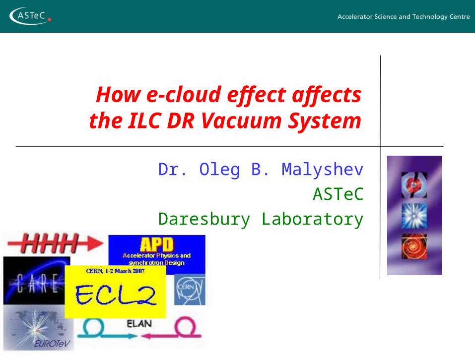
Vacuum studies vs e-cloud modelling
Vacuum science: Photon distribution, diffused
and forward scattered reflection
Photon induced electron production
Secondary electron production
Conditioning effects
Photon, electron and ion stimulated desorption
Gas density calculations
E-cloud modelling q(e-/m3) … …
Electron flux to the vacuum chamber walls
1-2 March, 2007 ECL-2, CERN O.B. Malyshev
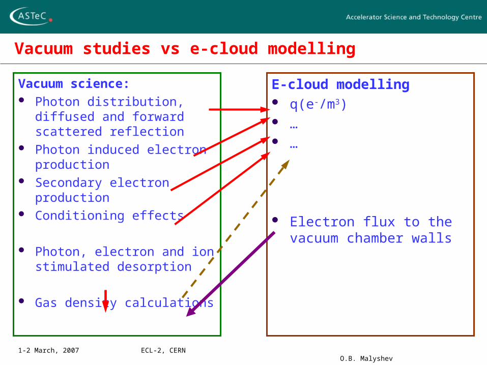
Photon reflectivity and azimuthal distribution
Exp. 1 Exp. 2
1-2 March, 2007 ECL-2, CERN O.B. Malyshev
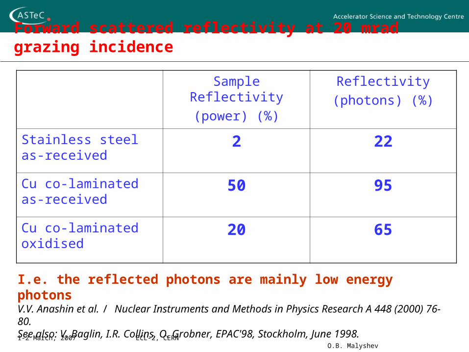
Forward scattered reflectivity at 20 mrad grazing incidence
Sample Reflectivity
(power) (%)
Reflectivity
(photons) (%)
Stainless steel as-received
2 22
Cu co-laminated as-received
50 95
Cu co-laminated oxidised
20 65
I.e. the reflected photons are mainly low energy photonsV.V. Anashin et al. / Nuclear Instruments and Methods in Physics Research A 448 (2000) 76-80.See also: V. Baglin, I.R. Collins, O. Grobner, EPAC'98, Stockholm, June 1998.
1-2 March, 2007 ECL-2, CERN O.B. Malyshev
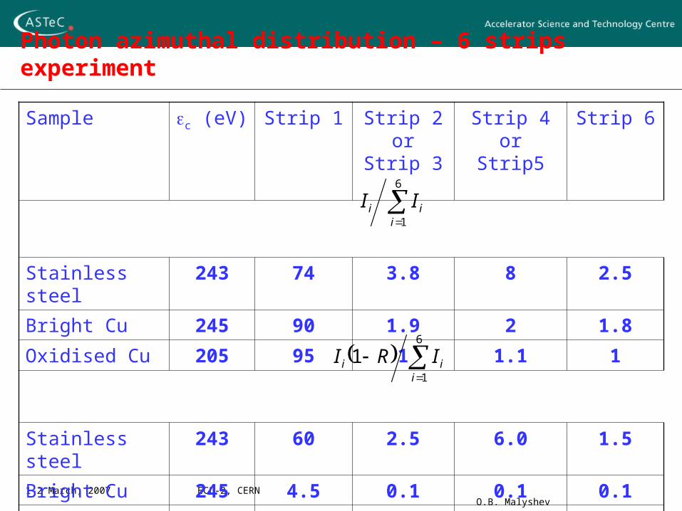
Photon azimuthal distribution – 6 strips experiment
Sample c (eV) Strip 1 Strip 2 or Strip 3
Strip 4 orStrip5
Strip 6
Stainless steel 243 74 3.8 8 2.5
Bright Cu 245 90 1.9 2 1.8
Oxidised Cu 205 95 1 1.1 1
Stainless steel 243 60 2.5 6.0 1.5
Bright Cu 245 4.5 0.1 0.1 0.1
Oxidised Cu 205 30 0.3 0.4 0.3
6
1iii II
6
1
1i
ii IRI
1-2 March, 2007 ECL-2, CERN O.B. Malyshev
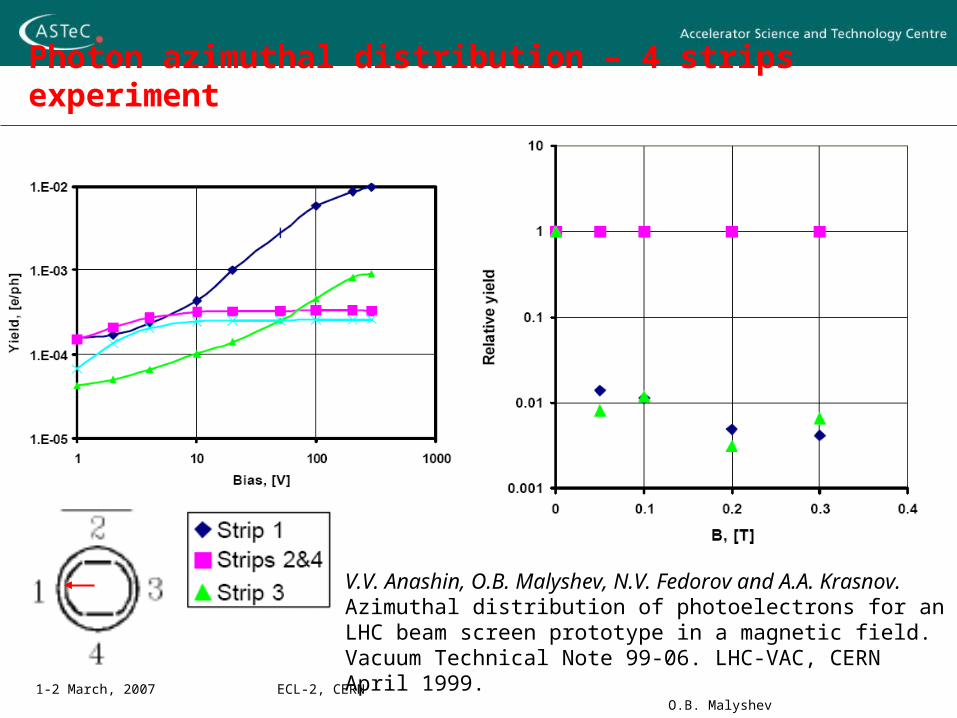
Photon azimuthal distribution – 4 strips experiment
V.V. Anashin, O.B. Malyshev, N.V. Fedorov and A.A. Krasnov. Azimuthal distribution of photoelectrons for an LHC beam screen prototype in a magnetic field. Vacuum Technical Note 99-06. LHC-VAC, CERN April 1999.
1-2 March, 2007 ECL-2, CERN O.B. Malyshev
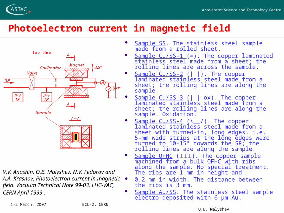
Photoelectron current in magnetic field Sample SS. The stainless steel sample made
from a rolled sheet. Sample Cu/SS-1 (=). The copper laminated
stainless steel made from a sheet; the rolling lines are across the sample.
Sample Cu/SS-2 (|||). The copper laminated stainless steel made from a sheet; the rolling lines are along the sample.
Sample Cu/SS-3 (||| ox). The copper laminated stainless steel made from a sheet; the rolling lines are along the sample. Oxidation.
Sample Cu/SS-4 (\__/). The copper laminated stainless steel made from a sheet with turned-in, long edges, i.e. 5-mm wide strips at the long edges were turned to 10–15° towards the SR; the rolling lines are along the sample.
Sample OFHC (). The copper sample machined from a bulk OFHC with ribs along the sample. No special treatment. The ribs are 1 mm in height and
0.2 mm in width. The distance between the ribs is 3 mm.
Sample Au/SS. The stainless steel sample electro-deposited with 6-μm Au.
V.V. Anashin, O.B. Malyshev, N.V. Fedorov and A.A. Krasnov. Photoelectron current in magnetic field. Vacuum Technical Note 99-03. LHC-VAC, CERN April 1999.
1-2 March, 2007 ECL-2, CERN O.B. Malyshev
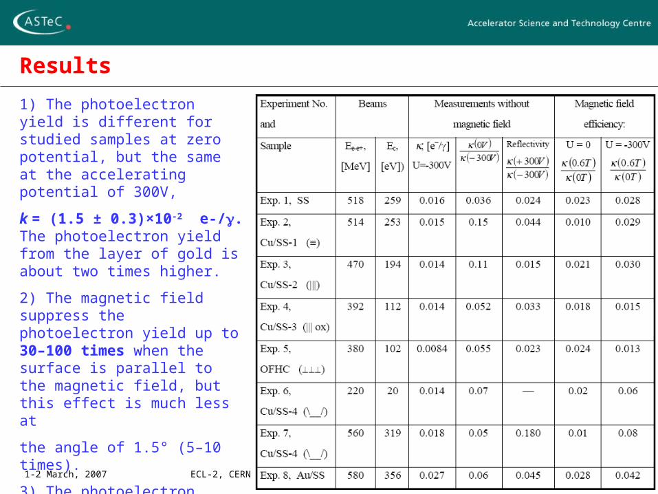
Results
1) The photoelectron yield is different for studied samples at zero potential, but the same at the accelerating potential of 300V,
k = (1.5 ± 0.3)×10-2 e-/. The photoelectron yield from the layer of gold is about two times higher.
2) The magnetic field suppress the photoelectron yield up to 30–100 times when the surface is parallel to the magnetic field, but this effect is much less at
the angle of 1.5° (5–10 times).
3) The photoelectron yield decreases with the accumulated photon dose: the photoelectron yield reduced 2–3 times at the accumulated photon dose of about
1022 photons/cm2.
1-2 March, 2007 ECL-2, CERN O.B. Malyshev
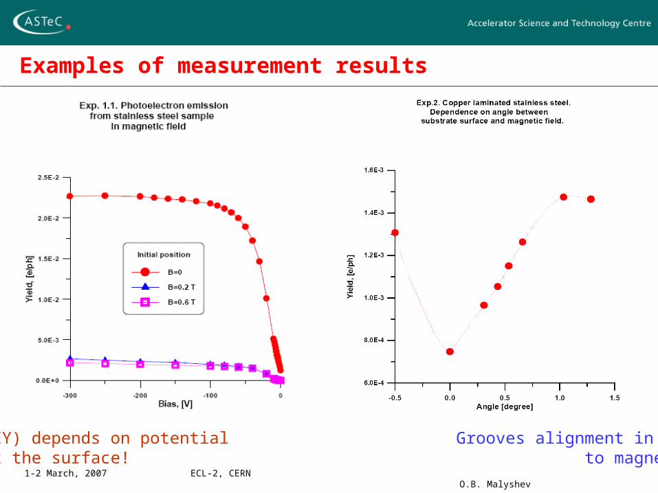
Examples of measurement results
PEY (and SEY) depends on potential Grooves alignment in respect gradient at the surface! to magnetic field
1-2 March, 2007 ECL-2, CERN O.B. Malyshev
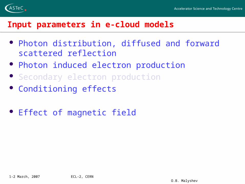
Input parameters in e-cloud models
Photon distribution, diffused and forward scattered reflection Photon induced electron production Secondary electron production Conditioning effects
Effect of magnetic field
1-2 March, 2007 ECL-2, CERN O.B. Malyshev
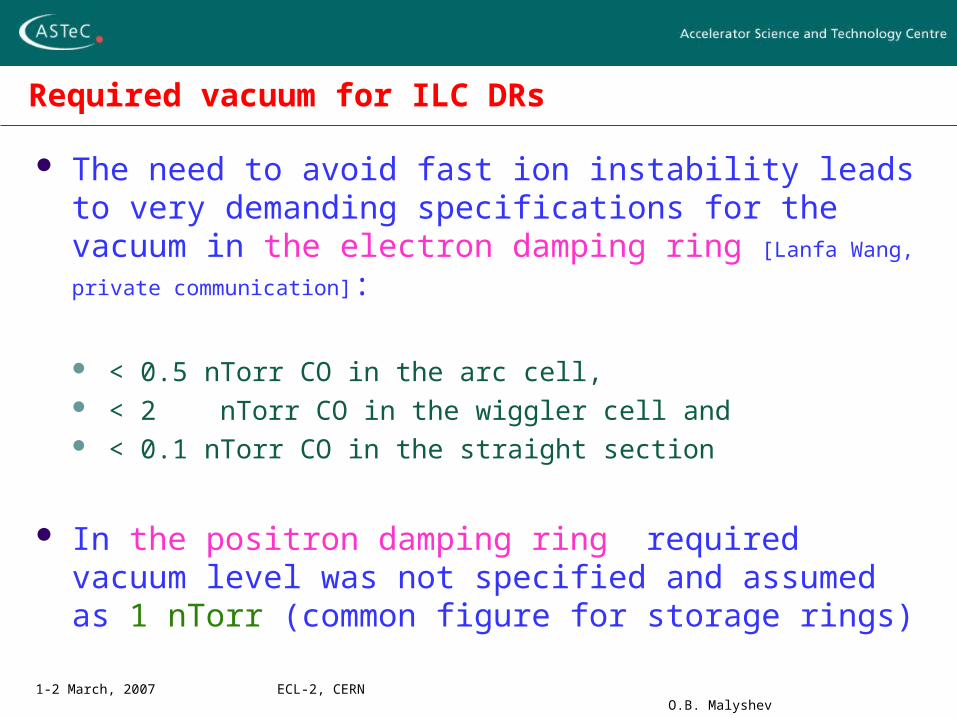
Required vacuum for ILC DRs
The need to avoid fast ion instability leads to very demanding specifications for the vacuum in the electron damping ring [Lanfa Wang, private communication]:
< 0.5 nTorr CO in the arc cell, < 2 nTorr CO in the wiggler cell and < 0.1 nTorr CO in the straight section
In the positron damping ring required vacuum level was not specified and assumed as 1 nTorr (common figure for storage rings)
1-2 March, 2007 ECL-2, CERN O.B. Malyshev
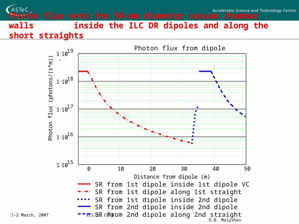
Photon flux onto the 50-mm diameter vacuum chamber walls inside the ILC DR dipoles and along the short straights
0 10 20 30 40 501 10
15
1 1016
1 1017
1 1018
1 1019
SR from 1st dipole inside 1st dipole VCSR from 1st dipole along 1st straightSR from 1st dipole inside 2nd dipole SR from 2nd dipole inside 2nd dipole SR from 2nd dipole along 2nd straight
Photon flux from dipole
Distance from dipole (m)
Pho
ton
flux
(ph
oton
s/(s
*m))
.
1-2 March, 2007 ECL-2, CERN O.B. Malyshev
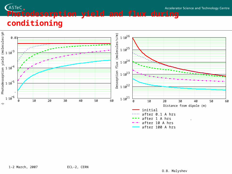
Photodesorption yield and flux during conditioning
0 50 100 150 200 250 300 350 4001 10
6
1 105
1 104
1 103
0.01
Pho
tode
sorp
tion
yie
ld (
mol
ecul
es/p
hoto
n)
0 10 20 30 40 50 601 10
6
1 105
1 104
1 103
0.01
Pho
tode
sorp
tion
yie
ld (
mol
ecul
es/p
hoto
n)
.
0 50 100 150 200 250 300 350 4001 10
11
1 1012
1 1013
1 1014
1 1015
1 1016
initialafter 0.1 A hrsafter 1 A hrsafter 10 A hrsafter 100 A hrs
Distance from dipole (m)
Des
orpt
ion
flux
(m
olec
ules
/s/m
)
0 10 20 30 40 50 601 10
11
1 1012
1 1013
1 1014
1 1015
1 1016
initialafter 0.1 A hrsafter 1 A hrsafter 10 A hrsafter 100 A hrs
Distance from dipole (m)
Des
orpt
ion
flux
(m
olec
ules
/s/m
)
0 50 100 150 200 250 300 350 4001 10
6
1 105
1 104
1 103
0.01
Pho
tode
sorp
tion
yie
ld (
mol
ecul
es/p
hoto
n)
0 10 20 30 40 50 601 10
6
1 105
1 104
1 103
0.01
Pho
tode
sorp
tion
yie
ld (
mol
ecul
es/p
hoto
n)
0 50 100 150 200 250 300 350 4001 10
11
1 1012
1 1013
1 1014
1 1015
1 1016
initialafter 0.1 A hrsafter 1 A hrsafter 10 A hrsafter 100 A hrs
Distance from dipole (m)
Des
orpt
ion
flux
(m
olec
ules
/s/m
)
0 10 20 30 40 50 601 10
11
1 1012
1 1013
1 1014
1 1015
1 1016
initialafter 0.1 A hrsafter 1 A hrsafter 10 A hrsafter 100 A hrs
Distance from dipole (m)
Des
orpt
ion
flux
(m
olec
ules
/s/m
).
1-2 March, 2007 ECL-2, CERN O.B. Malyshev
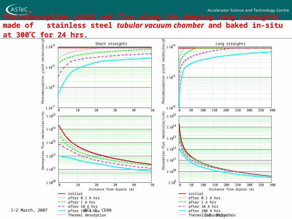
Photodesorption yield and flux along the damping ring straights made of stainless steel tubular vacuum chamber and baked in-situ at 300C for 24 hrs.
0 10 20 30 40 501 10
7
1 106
1 105
1 104 Short straights
Phot
odes
orpt
ion
yiel
d (m
olec
ules
/pho
ton)
0 50 100 150 200 250 300 350 4001 10
6
1 105
1 104 Long straights
Phot
odes
orpt
ion
yiel
d (m
olec
ules
/pho
ton)
0 10 20 30 40 501 10
10
1 1011
1 1012
1 1013
1 1014
1 1015
initialafter 0.1 A hrsafter 1 A hrsafter 10 A hrsafter 100 A hrsThermal desorption
Distance from dipole (m)
Des
orpt
ion
flux
(mol
ecul
es/s
/m)
0 50 100 150 200 250 300 350 4001 10
9
1 1010
1 1011
1 1012
1 1013
1 1014
1 1015
initialafter 0.1 A hrsafter 1 A hrsafter 10 A hrsafter 100 A hrsThermal desorption
Distance from dipole (m)
Des
orpt
ion
flux
(mol
ecul
es/s
/m)
1-2 March, 2007 ECL-2, CERN O.B. Malyshev
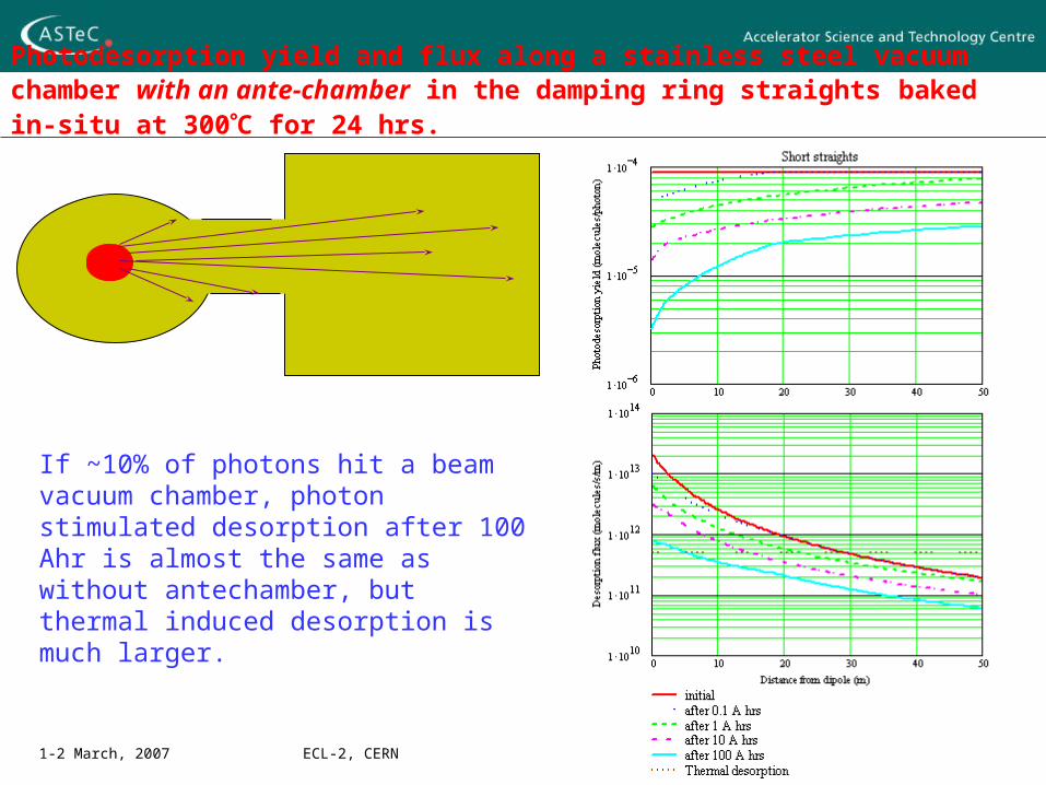
Photodesorption yield and flux along a stainless steel vacuum chamber with an ante-chamber in the damping ring straights baked in-situ at 300C for 24 hrs.
If ~10% of photons hit a beam vacuum chamber, photon stimulated desorption after 100 Ahr is almost the same as without antechamber, but thermal induced desorption is much larger.
1-2 March, 2007 ECL-2, CERN O.B. Malyshev
Tubular chamber vs a vacuum chamber with antechamber
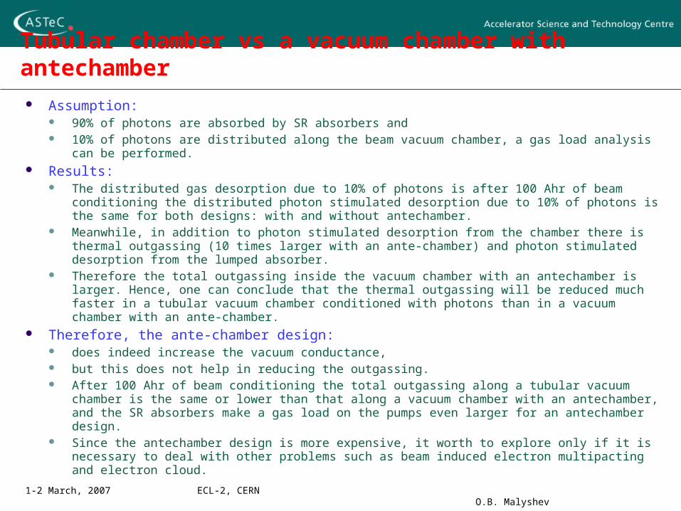
Assumption: 90% of photons are absorbed by SR absorbers and 10% of photons are distributed along the beam vacuum chamber, a gas load analysis can be
performed. Results:
The distributed gas desorption due to 10% of photons is after 100 Ahr of beam conditioning the distributed photon stimulated desorption due to 10% of photons is the same for both designs: with and without antechamber.
Meanwhile, in addition to photon stimulated desorption from the chamber there is thermal outgassing (10 times larger with an ante-chamber) and photon stimulated desorption from the lumped absorber.
Therefore the total outgassing inside the vacuum chamber with an antechamber is larger. Hence, one can conclude that the thermal outgassing will be reduced much faster in a tubular vacuum chamber conditioned with photons than in a vacuum chamber with an ante-chamber.
Therefore, the ante-chamber design: does indeed increase the vacuum conductance, but this does not help in reducing the outgassing. After 100 Ahr of beam conditioning the total outgassing along a tubular vacuum chamber is the
same or lower than that along a vacuum chamber with an antechamber, and the SR absorbers make a gas load on the pumps even larger for an antechamber design.
Since the antechamber design is more expensive, it worth to explore only if it is necessary to deal with other problems such as beam induced electron multipacting and electron cloud.
1-2 March, 2007 ECL-2, CERN O.B. Malyshev
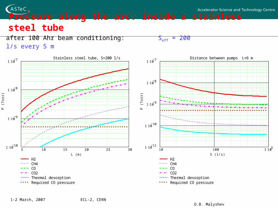
Pressure along the arc: inside a stainless steel tube
5 10 15 20 25 301 10
10
1 109
1 108
1 107
H2CH4COCO2Thermal desorptionRequired CO pressure
Stainless steel tube, S=200 l/s
L (m)
P (
To
rr)
10 100 1 1031 10
11
1 1010
1 109
1 108
1 107
H2CH4COCO2Thermal desorptionRequired CO pressure
Distance between pumps L=6 m
S (l/s)
P (
To
rr)
after 100 Ahr beam conditioning: Seff = 200 l/s every 5 m
1-2 March, 2007 ECL-2, CERN O.B. Malyshev
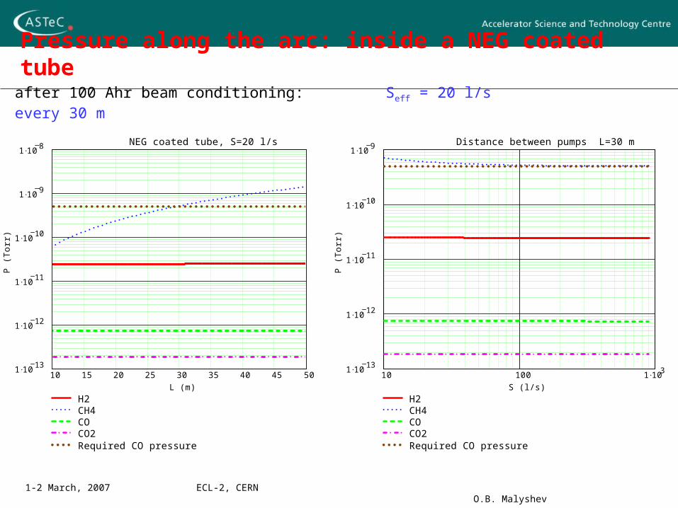
Pressure along the arc: inside a NEG coated tube
10 15 20 25 30 35 40 45 501 10
13
1 1012
1 1011
1 1010
1 109
1 108
H2CH4COCO2Required CO pressure
NEG coated tube, S=20 l/s
L (m)
P (T
orr)
10 100 1 1031 10
13
1 1012
1 1011
1 1010
1 109
H2CH4COCO2Required CO pressure
Distance between pumps L=30 m
S (l/s)
P (T
orr)
after 100 Ahr beam conditioning: Seff = 20 l/s every 30 m
1-2 March, 2007 ECL-2, CERN O.B. Malyshev
Main result of the modelling
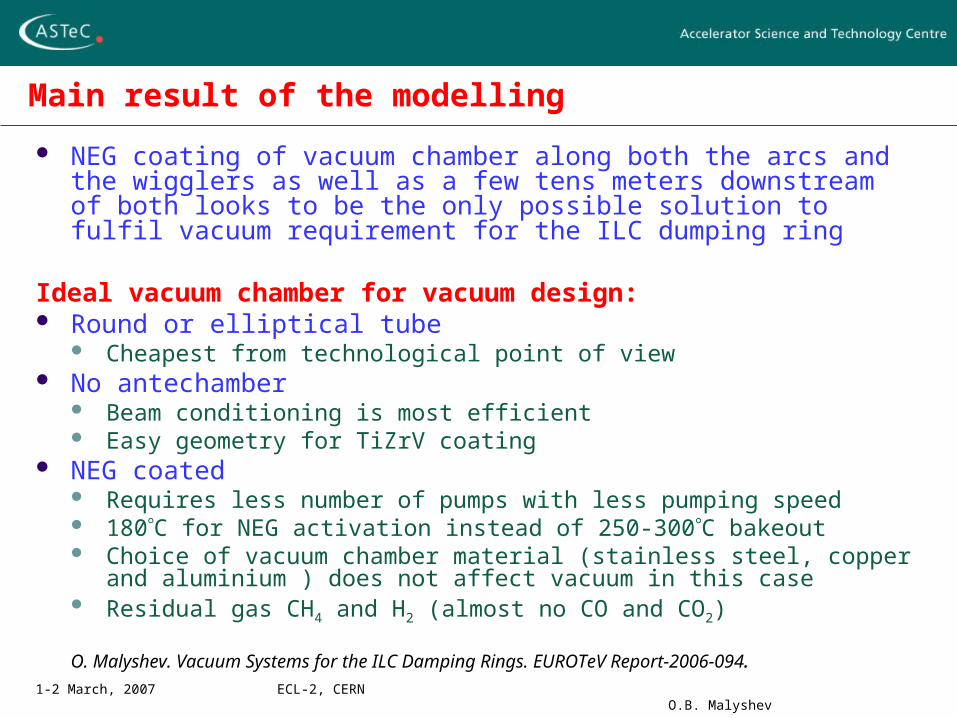
NEG coating of vacuum chamber along both the arcs and the wigglers as well as a few tens meters downstream of both looks to be the only possible solution to fulfil vacuum requirement for the ILC dumping ring
Ideal vacuum chamber for vacuum design: Round or elliptical tube
Cheapest from technological point of view No antechamber
Beam conditioning is most efficient Easy geometry for TiZrV coating
NEG coated Requires less number of pumps with less pumping speed 180C for NEG activation instead of 250-300C bakeout Choice of vacuum chamber material (stainless steel, copper and aluminium )
does not affect vacuum in this case Residual gas CH4 and H2 (almost no CO and CO2)
O. Malyshev. Vacuum Systems for the ILC Damping Rings. EUROTeV Report-2006-094.
1-2 March, 2007 ECL-2, CERN O.B. Malyshev
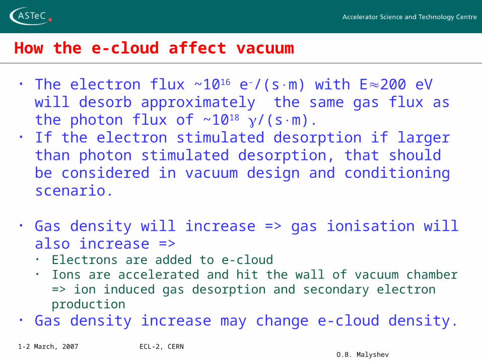
How the e-cloud affect vacuum
• The electron flux ~1016 e-/(sm) with E200 eV will desorb approximately the same gas flux as the photon flux of ~1018 /(sm).
• If the electron stimulated desorption if larger than photon stimulated desorption, that should be considered in vacuum design and conditioning scenario.
• Gas density will increase => gas ionisation will also increase =>• Electrons are added to e-cloud• Ions are accelerated and hit the wall of vacuum chamber => ion
induced gas desorption and secondary electron production• Gas density increase may change e-cloud density.
1-2 March, 2007 ECL-2, CERN O.B. Malyshev
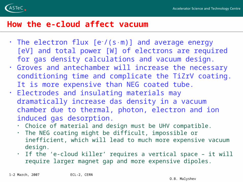
How the e-cloud affect vacuum
• The electron flux [e-/(sm)] and average energy [eV] and total power [W] of electrons are required for gas density calculations and vacuum design.
• Groves and antechamber will increase the necessary conditioning time and complicate the TiZrV coating. It is more expensive than NEG coated tube.
• Electrodes and insulating materials may dramatically increase das density in a vacuum chamber due to thermal, photon, electron and ion induced gas desorption. • Choice of material and design must be UHV compatible.• The NEG coating might be difficult, impossible or inefficient, which
will lead to much more expensive vacuum design.• If the ‘e-cloud killer’ requires a vertical space – it will require larger
magnet gap and more expensive dipoles.
1-2 March, 2007 ECL-2, CERN O.B. Malyshev
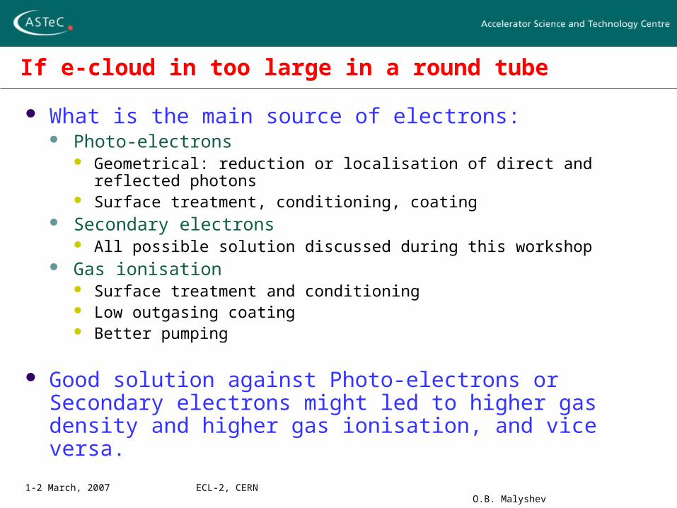
If e-cloud in too large in a round tube
What is the main source of electrons: Photo-electrons
Geometrical: reduction or localisation of direct and reflected photons Surface treatment, conditioning, coating
Secondary electrons All possible solution discussed during this workshop
Gas ionisation Surface treatment and conditioning Low outgasing coating Better pumping
Good solution against Photo-electrons or Secondary electrons might led to higher gas density and higher gas ionisation, and vice versa.
1-2 March, 2007 ECL-2, CERN O.B. Malyshev
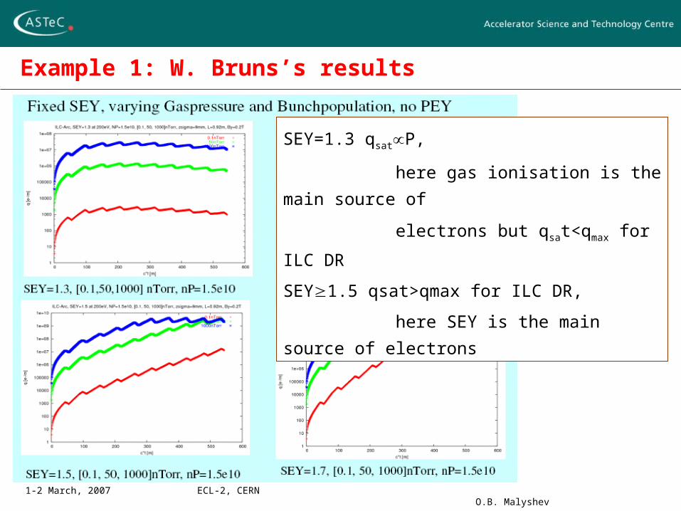
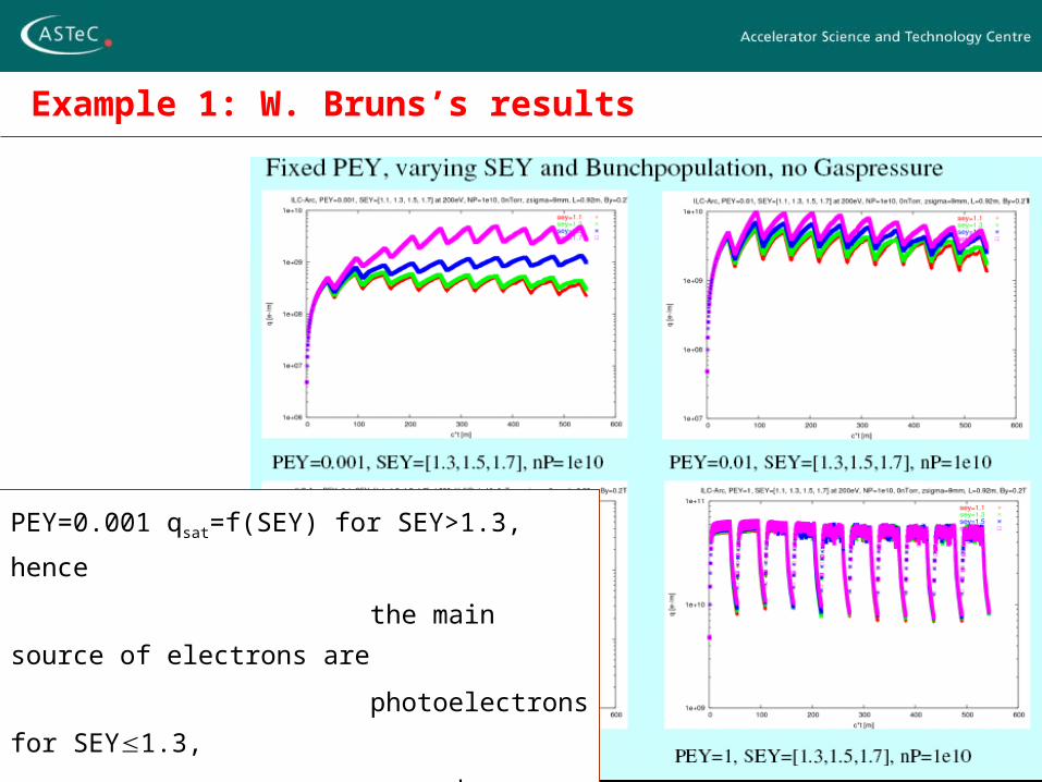
Example 1: W. Bruns’s results
SEY=1.3 qsatP,
here gas ionisation is the main source of
electrons but qsat<qmax for ILC DR
SEY1.5 qsat>qmax for ILC DR,
here SEY is the main source of electrons
1-2 March, 2007 ECL-2, CERN O.B. Malyshev
Example 1: W. Bruns’s results
PEY=0.001 qsat=f(SEY) for SEY>1.3, hence
the main source of electrons are
photoelectrons for SEY1.3,
secondary electrons for SEY >1.3.
PEY0.01 is the main source of electrons are photoelectrons