Hover Test of a Full-Scale Hingeless Rotor - NASA · Hover Test of a Full-Scale Hingeless Rotor ......
26
NASA Technical Memorandum 85990 i Hover Test of a Full-Scale Hingeless Rotor William Warmbrodt and Randall L. Peterson August 1984 8 National Aeronautics and Space Ad ministration https://ntrs.nasa.gov/search.jsp?R=19840025330 2018-07-06T03:05:12+00:00Z
Transcript of Hover Test of a Full-Scale Hingeless Rotor - NASA · Hover Test of a Full-Scale Hingeless Rotor ......

NASA Technical Memorandum 85990
i
Hover Test of a Full-Scale Hingeless Rotor William Warmbrodt and Randall L. Peterson
August 1984
8
National Aeronautics and Space Ad ministration
https://ntrs.nasa.gov/search.jsp?R=19840025330 2018-07-06T03:05:12+00:00Z
NASA Technical Memorandum 85990
Hover Test of a Full-Scale Hingeless Rotor William Warm brodt Randall L. Peterson, Ames Research Center, Moffett Field, California
National Aeronautics and Space Ad mi n 1st ration
Ames Research Center Moffett Field, California 94035

HOVER TEST OF A FULL-SCALE HINGELESS ROTOR
W i l l i a m Warmbrodt and Randal l L . Pe t e r son NASA Ames Research Center , Moffet t F i e l d , C a l i f o r n i a 94035, U.S.A.
ABSTRACT
The performance and a e r o e l a s t i c s t a b i l i t y i n hover of a 9.8-m-diam, h i n g e l e s s h e l i c o p t e r r o t o r system w a s eva lua ted . Rotor performance and inp lane damping da ta w e r e ob ta ined f o r r o t o r o p e r a t i o n between 350 and 425 rpm f o r t h r u s t c o e f f i c i e n t s (CT/CT) between 0.0 and 0 . 1 2 . A t cons t an t r o t o r t h r u s t , a minimum i n r o t o r inp lane damping w a s measured a t 400 rpm; t h e e f f e c t of exper imenta l d a t a s c a t t e r on t h i s damping t r e n d w a s determined t o be i n s i g n i f i c a n t . Good agreement i s shown between experimental performance d a t a and performance p r e d i c t e d by a comprehensive computer code. The in f luence of d i f f e r e n t aerody- namic in f low models on p r e d i c t i n g damping levels i s a l s o shown. The b e s t c o r r e l a t i o n wi th experimental s t a b i l i t y d a t a w a s ob ta ined when a dynamic inf low model w a s used ins tead of s t a t i c o r q u a s i - s t a t i c in f low models. D i r e c t comparisons were a l s o made between t h e h i n g e l e s s r o t o r d a t a and d a t a from a f u l l - s c a l e , b e a r i n g l e s s main r o t o r t e s t performed on t h e same general-purpose t es t appara tus . The aerodynamic e f f i c i e n c y of t h e b e a r i n g l e s s r o t o r w a s less a t low t h r u s t cond i t ions , bu t w a s t h e same a t des ign t h r u s t . A t low-thrust l e v e l s t h e b e a r i n g l e s s main r o t o r w a s less damped than t h e h inge le s s r o t o r .
NOMENCLATURE
b lade chord, m
r o t o r power c o e f f i c i e n t , r o t o r power/pS (RR)
r o t o r t h r u s t c o e f f i c i e n t , s h a f t axes , t h rus t /pS (RR)
v i scous damping of wind-tunnel ba lance modes, (N-sec)/m
r ig id -b lade p i t c h i n e r t i a about f e a t h e r i n g a x i s , kg*m
r o t o r c y c l i c c o n t r o l system s t i f f n e s s , N-mlrad
r o t o r r a d i u s , m
r o t o r r e fe rence area, 4cR, m
a i r d e n s i t y , kg/m3
damping decay c o e f f i c i e n t , sec-l ; r o t o r s o l i d i t y
ro tor -b lade fundamental inplane bending frequency, r ad / sec
2
2
68-1

nonrota t ing c y c l i c c o n t r o l system frequency, p e r rev a t d e s i g n t i p speed
n r o t o r r o t a t i o n frequency, r a d l s e c
1. INTRODUCTION
Future advances i n rotor-hub d e s i g n hold t h e promise of major improvements i n r o t o r c r a f t performance. Reducing t h e complexity of and t h e number of p a r t s i n t h e rotor-hub system w i l l improve hub aerody- namics, increase r e l i a b i l i t y , and reduce maintenance requirements . The c u r r e n t use of e l a s t o m e r i c b e a r i n g s h a s a l r e a d y reduced t h e complexity and s i z e of t h e hubs used i n many h e l i c o p t e r s . With h i n g e l e s s and b e a r i n g l e s s hubs, t h e c o n t r o l power w i l l a l s o be i n c r e a s e d over t h a t of h e l i c o p t e r s i n which t h e convent ional a r t i c u l a t e d r o t o r system i s used. Consequently, i t is l i k e l y t h a t t h e r e w i l l be s i g n i f i c a n t use of h i n g e l e s s and b e a r i n g l e s s r o t o r systems i n f u t u r e r o t o r c r a f t .
8
The des ign of t h e s e advanced rotor-hub systems w i l l r e q u i r e v a l i d a t e d a n a l y t i c a l codes t h a t can r e l i a b l y p r e d i c t r o t o r performance and s t a b i l i t y . Many exper imenta l s t u d i e s have been made i n which t h e emphasis was on e v a l u a t i n g t h e aeromechanical s t a b i l i t y of advanced rotor-hub systems. I n most of t h a t work, however, model-scale r o t o r systems were used. A s a r e s u l t , t h e r e are s t i l l q u e s t i o n s about geo- me t r i c , dynamic, and aerodynamic s c a l i n g and f a b r i c a t i o n d e t a i l s , and a need e x i s t s f o r a c c u r a t e l y d e f i n i n g t h e o p e r a t i o n a l c h a r a c t e r i s t i c s of f u l l - s c a l e h e l i c o p t e r r o t o r systems. Once t h e necessary d a t a a r e o b t a i n e d , they can be used t o v a l i d a t e t h e o r e t i c a l p r e d i c t i o n codes and t o i d e n t i f y areas where c u r r e n t a n a l y t i c a l t echniques must be f u r t h e r developed.
This paper p r e s e n t s r e s u l t s from a hover t es t of a BO-105 h e l i - c o p t e r r o t o r system i n t h e 40- by 8O-Foot Wind Tunnel tes t s e c t i o n a t A m e s Research Center ( f i g . 1 ) . Rotor aerodynamic performance and aero- e l a s t i c inplane damping d a t a were obta ined f o r r o t o r o p e r a t i o n between 350 and 425 rpm (des ign speed) , and f o r r o t o r t h r u s t c o e f f i c i e n t s (C,/U) between 0.0 and 0.12. r e l a t i v e l y few well-documented a e r o e l a s t i c s t a b i l i t y d a t a sets t h a t e x i s t f o r f u l l - s c a l e h i n g e l e s s - r o t o r systems; see r e f . 1 f o r d e t a i l s . ) A comprehensive r o t o r c r a f t computer code ( r e f . 2) was then used t o pre- d i c t t h e r o t o r hover performance f o r t h e s a m e c o n d i t i o n s , and t h e pre- d i c t i o n s and exper imenta l d a t a w e r e compared. The s e n s i t i v i t y of pre- d i c t e d performance t o d i f f e r e n t rotor-wake models w a s a l s o i n v e s t i g a t e d , as w e l l as t h e e f f e c t s on p r e d i c t e d s t a b i l i t y levels of vary ing t h e number of genera l ized blade-and-body degrees of freedom, of b lade s t r u c - t u r a l damping, and of control-system s t i f f n e s s .
(These t e s t r e s u l t s c o n s t i t u t e one of t h e
A s repor ted by v a r i o u s o t h e r r e s e a r c h e r s , t h e u s e of a n unsteady aerodynamic model (dynamic inf low) can s i g n i f i c a n t l y improve t h e cor re- l a t i o n between p r e d i c t e d and experimental r e s u l t s . The r e s u l t s from a n a n a l y t i c a l model without dynamic inf low, wi th a q u a s i - s t a t i c in f low model, and wi th a dynamic inf low model are compared w i t h t h e exper i - mental da t a . publ i shed damping d a t a f o r t h e same r o t o r system.
The d a t a presented h e r e are a l s o compared wi th p r e v i o u s l y Those p r e v i o u s l y
68-2

Figure 1. BO-105 r o t o r system on Ames Rotor T e s t Apparatus i n 40- by 8O-Foot Wind Tunnel test sec t ion .
r epor t ed d a t a ( r e f . 3) w e r e obtained on a whirl-tower, whereas a wind- t u n n e l support system was used i n t h e p re sen t study. The new d a t a set is a l s o used h e r e t o make d i r e c t comparisons with f u l l - s c a l e , bearing- less main r o t o r d a t a obtained on t h e same wind-tunnel support system ( r e f . 4 ) .
2. TEST HARDWARE
The BO-105 h e l i c o p t e r rotor system is a four-bladed, s o f t inplane (us c Q) r o t o r with constant chord (0.27 m), -8" l i n e a r t w i s t , and a NACA 23012 a i r f o i l . The r o t o r r ad ius is 4.91 m; r o t o r s o l i d i t y ((5) is 0.070. sweep of t h e blade outboard of the p i t c h bea r ing ( f i g . 2 ) . The BO-105 r o t o r used i n t h i s test was a production r o t o r set p rev ious ly used i n a f l i g h t - t e s t program. Additional d e t a i l s about t h e r o t o r system are p resen ted i n r e fe rence 5. Calculated r o t a t i n g coupled-bending and uncoupled-torsion frequencies at t h e design t i p speed of 218 m/sec (425 rpm) are presented i n t a b l e 1.
The r o t o r hub h a s 2.5" of b u i l t - i n coning and zero droop o r
The r o t o r was i n s t a l l e d on t h e Rotor T e s t Apparatus a t Ames ( f i g . 1). f o r ope ra t ing h e l i c o p t e r r o t o r s i n t h e 40- by 8O-Foot Wind Tunnel.
Th i s apparatus is a special-purpose d r i v e and support system It
68-3

Figure 2 . BO-105 h inge less - ro tor hub.
Table 1.- Calculated r o t a t i n g blade frequencies (per rev) a t 425 rpm
F i r s t Second Third mode mode mode
Flapwise 1.10 2.75 4.89 Edgewise 0.73 4.46 11.54 Torsion 3.56 6.48 10.73
houses two e l e c t r i c d r i v e motors, t h e hydrau l i c s e rvoac tua to r s of t h e primary c o n t r o l system, and a dynamic c o n t r o l system capable of in t roducing dynamic pe r tu rba t ions t o t h e nonro ta t ing swashplate (co l - lect ive and t i l t ) a t f requencies up t o 30 Hz. This system w a s used dur ing t e s t i n g t o e x c i t e t h e r o t o r a t i ts fundamental inp lane bending frequency f o r s t a b i l i t y measurements.
A shake test w a s performed be fo re t h e p r i n c i p a l test t o de t e r -
A blades-off hub mine t h e dynamic c h a r a c t e r i s t i c s of t h e test appara tus and of t h e ba l - ance system wi th the e i g h t balance dampers engaged. conf igura t ion w a s used. Th i s test w a s conducted, i n p a r t , t o determine any changes i n the wind-tunnel balance dynamics owing t o r ecen t modifi- c a t i o n s i n its ope ra t iona l conf igu ra t ion . The r e s u l t s a r e presented i n t a b l e 2 f o r both long i tud ina l and l a t e r a l e x c i t a t i o n a t t h e hub. quency and damping levels f o r t h e lowest balance and s t r u t modes a r e shown. A l s o shown i n t a b l e 2 are t h e r e s u l t s from t h e most r ecen t pre- v ious shake test ( 1 9 7 8 ) , performed i n a similar manner, before the balance system modif icat ion; t h e support-system f requencies are essen- t i a l l y unchanged, although damping l e v e l s are d i f f e r e n t .
Fre-
68-4

J
Table 2.- Support-system dynamic c h a r a c t e r i s t i c s f o r BO-105 h over t e s t
1978 r e s u l t s D i r e c t i o n of e x c i t a t i o n Mode w, Hz C c , N * s e c / m
o, Hz C c y N * s e c / m
Longi tudina l Balance 2.24 119,600 2.14 88,400
2.63 43,800
4.22 43,900
4.56 30,600
S t r u t 4.17 49 , 160
Lateral Balance 2.71 51 , 900 S t r u t 4.64 35 , 940
3. PERFORMANCE TESTING
Hover t e s t i n g of t h e BO-105 r o t o r system was performed wi th t h e wind-tunnel access doors open and wi th t h e r o t o r s h a f t t i l t e d forward 10" t o reduce a i r f l o w r e c i r c u l a t i o n ( f i g . 1). T e s t c o n d i t i o n s were e s t a b l i s h e d by s e t t i n g t h e r o t o r r o t a t i o n speed and r o t o r t h r u s t coef- f i c i e n t (CT/O). per - revolu t ion f l a p p i n g , as measured us ing a r e s o l v e d , f l a p w i s e bending- moment s i g n a l from t h e b lade r o o t a t s t a t i o n 0.10R. Both l o n g i t u d i n a l and la teral c y c l i c p i t c h i n p u t s of t h e o r d e r of 50.2" were r e q u i r e d t o n u l l t h i s once-per-revolution f lapping .
Cycl ic p i t c h w a s t h e n used t o nominally n u l l any once-
4 . STABILITY TESTING
A t r a n s i e n t decay t ime-his tory from a n edgewise bending-moment s i g n a l ( s t a t i o n 0.10R) was used to determine system s t a b i l i t y . The damping leve l w a s determined f o r only t h e fundamental edgewise bending mode. A f t e r o b t a i n i n g t h e d e s i r e d o p e r a t i n g c o n d i t i o n s , t h e dynamic c o n t r o l system w a s used t o o s c i l l a t e t h e c y c l i c p i t c h of t h e r o t o r a t t h e r o t o r - r e g r e s s i n g inp lane bending frequency (nuta t ion- type e x c i t a - t i o n ) . A chordwise bending-moment s i g n a l w a s monitored, and t h e ampli- t u d e of t h e o s c i l l a t i o n of t h e swashplate w a s increased u n t i l e i t h e r a n adequate s i g n a l a t t h e f o r c i n g frequency w a s ob ta ined i n t h e b lade chordwise bending moment, o r u n t i l a load l i m i t was reached a t any of t h e instrumented b lade s t a t i o n s . Abrupt t e r m i n a t i o n of t h e e x c i t a t i o n y i e l d e d t h e t r a n s i e n t decay of t he b l a d e edgewise bending-moment s i g n a l . T h i s s i g n a l w a s recorded and analyzed u s i n g t h e moving-block technique. Several s t a b i l i t y records were obtained a t each o p e r a t i n g c o n d i t i o n . An 8-sec p o r t i o n of t h e decaying analog s i g n a l w a s d i g i t i z e d and a s p e c t r a l a n a l y s i s w a s made. Using a n a p p r o p r i a t e l y s e l e c t e d 5-sec por- t i o n of t h e t ime-his tory , t h e t r a n s i e n t s i g n a l w a s analyzed u s i n g a one-quarter ( o r 1.25 sec ) b lock s i z e a t t h e fundamental edgewise bend- i n g frequency .
A s mentioned above, e x c i t a t i o n of b lade chordwise bending motion
Because of t h i s c o n t r o l i n p u t , t h e r o t o r responded t o w a s accomplished by o s c i l l a t i n g the swashplate a t the r e g r e s s i n g inp lane modal frequency. b lade-p i tch motion a t t h e r e g r e s s i n g i n p l a n e modal f requency i n t h e
r o t a t i n g system. The r e s u l t i n g t r a n s i e n t decay record ob ta ined from t h e chordwise bending-moment s i g n a l consequent ly y i e l d e d t h e damping informat ion f o r t h e r eg res s ing inp lane mode. i np lane mode w a s no t e x c i t e d , i t should not contaminate t h e t r a n s i e n t decay t ime-his tory d a t a o r t h e damping de te rmina t ion . technique i s considered s u p e r i o r t o e i t h e r s t e p o r impulse i n p u t s t o t h e r o t o r c o n t r o l system o r body modes s i n c e i t does n o t r e q u i r e t i m e - h i s t o r i e s f rom each b lade (and a subsequent mul t ib l ade coord ina te t r a n s - formation) t o determine t h e r o t o r i np lane modal c h a r a c t e r i s t i c s . It should be noted t h a t t h i s means of rotor-mode e x c i t a t i o n could a l s o be used t o e x c i t e t h e progress ing inp lane mode s e p a r a t e l y , a l though t h i s w a s no t done i n t h i s t es t . However, a n a l y t i c a l r e s u l t s are d i scussed i n t h i s paper t o demonstrate t h a t t h e exper imenta l d a t a are f o r t h e r e g r e s s i n g inp lane mode, which i s t y p i c a l l y t h e most important r o t o r mode f o r aeromechanical c o n s i d e r a t i o n s such as ground o r a i r resonance.
S ince t h e p rogres s ing
This e x c i t a t i o n
A .9
.8
5 . RESULTS
rpm 0 350 0 375
- 0 400
- -
Rotor Performance Data
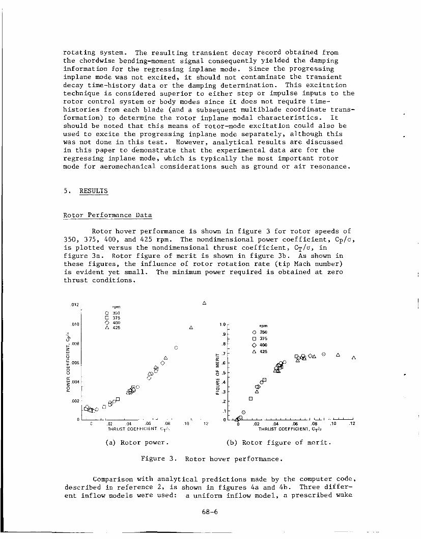
Rotor hover performance i s shown i n f i g u r e 3 f o r r o t o r speeds of 350, 375, 400, and 425 rpm. The nondimensional power c o e f f i c i e n t , Cp/a, is p l o t t e d versus t h e nondimensional t h r u s t c o e f f i c i e n t , C T / U , i n f i g u r e 3 a . Rotor f i g u r e of m e r i t i s shown i n f i g u r e 3b. A s shown i n t h e s e f i g u r e s , t h e in f luence of r o t o r r o t a t i o n r a t e ( t i p Mach number) is ev iden t ye t s m a l l . The minimum power r equ i r ed is obta ined a t zero t h r u s t cond i t ions .
012
010
P U +. 008
5
s
- u 006
w
(z. $ 004 0
002
0
0 400 A 425
0
n
0 I) 1 , -L--- -~- i 1 ,
0 02 04 06 08 10 12 0 .02 04 06 .08 . lo . I2 THRUST COEFFICIENT CT/ THRUST COEFFICIENT, CT/U
(a) Rotor power. (b) Rotor f i g u r e of m e r i t .
F igure 3 . Rotor hover performance.
Comparison with a n a l y t i c a l p r e d i c t i o n s made by t h e computer code, descr ibed i n r e f e rence 2, is shown i n f i g u r e s 4a and 4b. Three d i f f e r - e n t in f low models were used: a uniform in f low model, a p r e s c r i b e d wake
68-6

.010
D a. . - u - +- ,008 - z - Y - 0 - ,006 - U
8 -
0 n
. O 0 i
A EXPERIMENT - UNIFORM INFLOW -- PRESCRIBED WAKE (REF 6 )
PRESCRIBED WAKE (REF 7)
c - - K -
.6 -
U 0 - Y -
5 .4 -
U
K 0 .2 + - -
B -
( a ) Rotor power. (b) Rotor f i g u r e of m e r i t .
F igu re 4. P r e d i c t e d r o t o r performance, 425 rpm.
model based on t h a t of Landgrebe ( r e f . 6 ) , and a p r e s c r i b e d wake model based on t h a t of Kocurek and Tangler ( r e f . 7 ) . Each a n a l y s i s u s e s two e l a s t i c - b l a d e bending modes p l u s a r ig id -b lade and one e l a s t i c - b l a d e t o r s i o n mode. F igu re 4a shows the p r e d i c t e d power v e r s u s t h r u s t cu rves f o r a r o t o r speed of 425 rpm. A t t h r u s t levels below CT/G = 0.06, the u i i f o r m in f low model c o r r e l a t e s we l l . However, a t h igh t h r u s t l e v e l s , t h e power r e q u i r e d is p r e d i c t e d w e l l w i t h t h e Landgrebe wake model. The s a m e d a t a are p resen ted i n f i g u r e 4b i n terms of r o t o r f i g u r e of m e r i t (FM). For CT/U 0.08, the uniform in f low model g ives t h e b e s t c o r r e l a t i o n . Y e t , on ly t h e Landgrebe wake model p r e d i c t s a r e d u c t i o n i n FM a t h i g h t h r u s t (0.10 < CT/U < 0 .12) . two p r e s c r i b e d wake models f o r t h i s r o t o r system is shown i n f i g u r e 5. I n f i g u r e 5a , t h e nondimensional r a d i a l l o c a t i o n of t h e t i p v o r t e x benea th t h e r o t o r b l ade a t t h e f i r s t following-blade encounter shows l i t t l e d i f f e r e n c e between t h e two models. However, t h e nondimensional v e r t i c a l s e p a r a t i o n d i s t a n c e between t h e t i p v o r t e x and t h e f i r s t f o l - lowing b l ade ( f i g . 5b) shows d i f f e r e n c e s of about 15% between t h e two models.
The d i f f e r e n c e between t h e s e
The importance of t h e e f f e c t of t h e v e r t i c a l l o c a t i o n of t h e wake t i p v o r t i c e s on performance i s f u r t h e r i l l u s t r a t e d i n f i g u r e 6. I n f i g u r e 6a, t h e v e r t i c a l convection rate (k2) i n t h e f a r wake ( a f t e r t h e f i r s t following-blade passage) as a f u n c t i o n of r o t o r t h r u s t is shown f o r t h r e e d i f f e r e n t p re sc r ibed wake models: (1) t h e Landgrebe model ( r e f . 6 ) ; ( 2 ) t h e Tangler-Kocurek model ( r e f . 7 ) ; and ( 3 ) a modi- f i e d p r e s c r i b e d wake model where k, w a s ob ta ined by matching t h e p re - d i c t e d r o t o r performance wi th the exper imenta l d a t a . For C T / G = 0.12, t h e modified v a l u e i s t h e same as would be ob ta ined us ing t h e model of r e f e r e n c e 6. However, f o r 0.08 < CT/U < 0.11, t h e modified v a l u e is j u s t s l i g h t l y g r e a t e r than t h e v e r t i c a l convec t ion ra te of r e f e r e n c e 7 . For CT/a < 0.08, a n in t e rmed ia t e v a l u e f o r k2 w a s s e l e c t e d t o b e s t p r e d i c t t h e exper imenta l r e s u l t s . The c a l c u l a t e d performance u s i n g t h i s modified wake model i s shown i n f i g u r e s 6b and 6c f o r r o t o r power
68-7

- _ REF. 6 (LANDGREBE) REF. 7 (KOCUREK AND TANGLER)
N
.10 r K - n g .08 - - - I- % : J .06
- 1 -
5 a
- ’ 0 . K .04 -
0 .02 .04 .06 .08 .10 .12 THRUST COEFFICIENT, CT/O
(a) Rad ia l l o c a t i o n inboard from blade t i p (I R ) .
0 .02 .04 .06 .08 .10 .12
THRUST COEFFICIENT, CT/o
(b) V e r t i c a l l o c a t i o n below b l a d e ( f R) .
Figure 5 . T r a j e c t o r y of p r e s c r i b e d wake t i p v o r t e x a t f i r s t fo l lowing b l ade passage .
A 425 rpm - MODIFIED PRESCRIBED WAKE MODEL
,013 r
_ _ REF. 6 ILANDGREBE)
- MODIFIED PRESCRIBED WAKE MODEL REF. 7 (KOCUREK AND TANGLER)
N y .lor K- w - W I - -
5 .08 - E - a n
$ .06 -
2 : u W
K I- 2 .04 -
:: ; .02 - 0 > r
.02 .04 .06 .08 .10 .12 CT/o
0 0 .02 .04 .06 .08 .10 .12
CTlO
(a) Axial s lope of t i p v o r t e x t r a j e c - (b) Rotor power. t o r y a f t e r f i r s t b l a d e passage .
F igu re 6. P r e d i c t e d aerodynamic performance wi th modified p r e s c r i b e d wake model: 425 rpm.
68-8

and r o t o r f i g u r e of merit, respec- t i v e l y . These r e s u l t s were ob ta ined us ing t h e o t h e r r o t o r - -
wake parameters as c a l c u l a t e d by r e f e r e n c e 6 . Desp i t e on ly a
l o c a t i o n of t h e t i p v o r t i c e s i n t h e f a r wake, good c o r r e l a t i o n i s ob ta ined .
s l i g h t change t o t h e v e r t i c a l .6
u K - 3 - 0 c.2
Rotor S t a b i l i t y Data .
h
-
1
- - -
0 1 2 ' ' I " " " " ' ' I ' I ' " " J
A 425 rprn - MODIFIED PRESCRIBED WAKE MODEL
Using t h e polynomial curve f i t s from f i g u r e 7 , damping t r e n d s wi th cons t an t r o t o r t h r u s t and changing r o t o r speed are summarized i n
CURVE FIT 0
H -2.01 .
t
p -1.5 d
THRUST COEFFICIENT, cT/fJ
0 0 .02 .04 .06 .08 .10
THRUST COEFFICIENT, CT/U
( a ) 350 rpm. (b) 375 rpm.
F i g u r e 7. Rotor r e g r e s s i n g inp lane modal damping d a t a wi th polynomial curve f i t .
68-9

-“I -2.0
r I
-1.5-
I--
w - 2 -
; -1.0-
8 - 9 - 5 -
u - w .
> -
w - n
0
-
-‘g
Constant r o t o r t h r u s t con- -
W 0
0
owing t o exper imenta l d a t a
d i t i o n s , 0.0 5 C T / U < 0.04,
0.02
- s c a t t e r . For low- thrus t con-
0 0 .02 .04 .06 .08 .10
THRUST COEFFICIENT, C ~ l n
0 0 .02 .04 .06 .08 .10
THRUST COEFFICIENT, CT/O
(c) 400 rpm. (d) 4 2 5 rpm.
F igure 7 . Concluded.
68-10

.
-2.0 c ,
p l o t t e d . The exper imenta l ly mea- sured inp lane frequency w c w a s used t o c a l c u l a t e t h e r e g r e s s i n g inp lane modal frequency (52 - w C ) . Consequently, t h e reduced r e g r e s s i n g i n p l a n e modal damp- ing a t h i g h e r t h r u s t levels , C T ~ O 1 0.04 ( f i g . 7) , and a t 400 rpm could be due t o a resonant o p e r a t i n g c o n d i t i o n . T h i s i s , however, n o t supported by a n a l y t i c a l r e s u l t s (d i scussed l a t e r ) . A s mentioned previous ly , t h e i n c r e a s e i n damping a t C T / O = 0.0 r e l a t i v e t o CT/O = 0.02 f o r each r o t a t i o n a l speed.
i s c l e a r l y seen
PARTICULAR OPERATING CONDITION
I DATA SCATTER it CURVE FIT ~ I
I
A s p a r t of t h i s s tudy , an a t tempt w a s made t o e v a l u a t e the s i g n i f i c a n c e of u s i n g polynomial curve f i t s t o t h e experimental
0 0 .02 .04 .06 .08 .10
THRUST COEFFICIENT, CT/o
(a ) 350 rpm.
F i g u r e 10 . Polynomial curve f i t of
0 REGRESSING INPLANE MODE
2
U x it U
LATERAL BALANCE MODE -_ - - - - - - - - - - Q - - - - - - - -0- - --
LONGITUDINAL BALANCE MODE
8 8
I I 1
375 400 425 ROTOR ROTATIONAL SPEED, rpm
F i g u r e 9 . Inp lane r e g r e s s i n g modal f requency as a f u n c t i o n of r o t o r r o t a t i o n a l speed (C,/O = 0.07).
d a t a ( f i g . 7) t o i n v e s t i g a t e damping t r e n d s w i t h r o t o r t h r u s t and r o t a - t i o n ra te ( f i g . 8 ) . I n doing so , an estimate of t h e e f f e c t s of d a t a scat ter on measured damping levels and r e s u l t a n t t r e n d s can be more c l o s e l y reviewed. T h i s i s important i n unders tanding t h e e f f e c t of exper imenta l d a t a sca t te r on observed damping t r e n d s and h a s n o t been thoroughly addressed i n prev ious s t u d i e s . I n f i g u r e s lOa-lOd, t h e p l o t t e d d a t a p o i n t s are t h e midpoints of t h e d a t a range a t t h a t par- t i c u l a r thrust c o n d i t i o n f o r r o t o r speeds of 350, 375, 400, and 425 rpm. The v e r t i c a l b a r s show t h e range of d a t a s c a t t e r a t t h e s e t h r u s t
-1.5 d L - t
0 .02 .04 .06 .08 .10 THRUST COEFFICIENT, C T / ~
(b) 375 rpm.
(max-min)/ 2 r e g r e s s i n g i n p l a n e modal damping d a t a a t each o p e r a t i n g c o n d i t i o n .
68-11

[ - l . o / U W
8
-2 5
-20 r
0 2 d
Y 0
5 - 1 5
U L w 8 - 1 0 -
a u >
w 0
- 5
0
w n
-
-2 0 - -
r
u 2-15- d I-- z w
-
p - l o -
8 9 - 5 -
U w
t
W -
0
o - ' " " " ' ' ~ ' ' ~ " ' ' ' " " " 0 02 04 06 08 10
1 ' I " " " ' I ' I I " ' I I ' I I ' I
0 02 04 06 08 10
-2.0 - r
0 2 3: 5 -1.5 Y 2
-
L U w 8 -1.0 - t
u w 0
a
-.5 -
0 0 .02 .04 .06 .08 .10
THRUST COEFFICIENT, CT/o
0 0 .02 .04 .06 .08 .10
THRUST COEFFICIENT, CT/o
( c ) 400 rpm. (d) 425 rpm.
F igure 10. Concluded.
c o n d i t i o n s . The s o l i d curves are a g a i n second-order, l e a s t - s q u a r e s polynomial r e g r e s s i o n curves f o r t h e s e mid-range d a t a and t h e dashed curves are f o r t h e maximum and minimum extrema. A somewhat d i f f e r e n t set of va lues is shown i n f i g u r e s l l a - l l d where t h e p l o t t e d d a t a p o i n t
( a ) 350 rpm. (b) 375 rpm.
F i g u r e 11. Polynomial curve f i t of average r e g r e s s i n g inp lane modal damping d a t a a t each o p e r a t i n g c o n d i t i o n .
68-12

' -1.5 d -2'oi
i c
0 .02 .G4 .06 .08 .10 THRUST COEFFICIENT, CT/Q
0 0 .02 .04 .06 .08 .10
THRUST COEFFICIENT, CT/Q
(c) 400 rpm. (d) 4 2 5 rpm.
F igu re 11.. Concluded.
a t each o p e r a t i n g c o n d i t i o n is the average v a l u e c a l c u l a t e d from a l l of t h e d a t a a t t h a t p a r t i c u l a r t h r u s t . The shaded a r e a shows the range of expe r imen ta l ly determined decay c o e f f i c i e n t s . The v e r t i c a l b a r s i n f i g u r e 11 are p l u s o r minus one s t anda rd d e v i a t i o n determined from t h e s e d a t a . Again t h e curves a r e second-order r e g r e s s i o n cu rves of t h e s e average d a t a .
Using t h e curve f i t s of f i g u r e s 10 and 11, damping t r e n d s wi th c o n s t a n t r o t o r t h r u s t and changing r o t o r speed are determined. I n f i g u r e 12a, t h e r e s u l t i n g curves from t h e mid-range d a t a ( f i g . 10) are used , and i n f i g u r e 12b, t h e r e s u l t i n g curves from t h e averaged d a t a ( f i g . 12) are used. The v e r t i c a l b a r s i n f i g u r e 12a are t h e polynomial curve f i t s t o t h e extrema of t h e d a t a scatter a t CT/O = 0.04, 0.06, and 0.08. The ver t ical b a r s i n f i g u r e 12b are polynomial c u r v e - f i t s f o r one s t anda rd d e v i a t i o n a t CT/U = 0.04, 0.06, and 0.08 ( f i g . 11). F i g u r e s 12a and 12b can be d i r e c t l y compared wi th f i g u r e 8 t o determine t h e i n f l u e n c e of exper imenta l da ta s c a t t e r on t h e damping t r e n d s a t c o n s t a n t t h r u s t w i t h i n c r e a s i n g r o t o r r o t a t i o n r a t e . Recall t h a t f i g - u r e 8 w a s ob ta ined us ing curves ( f i g . 7) ob ta ined by u s i n g a r e g r e s s i o n a n a l y s i s w i th each damping de termina t ion cons idered s e p a r a t e l y . o b s e r v a t i o n s can be made. A t 350 rpm, t h e midpoint d a t a curve ( f i g . 12a) shows h i g h e r damping a t CT/O = 0.08 and lower damping a t CT/U = 0.02 t h a n t h e o t h e r f i g u r e s . However, a l l t h r e e curves (and consequent ly a l l t h r e e ways of account ing f o r da t a s c a t t e r ) show t h e s a m e two major t r e n d s w i t h c o n s t a n t t h r u s t : (1) a t high t h r u s t c o e f f i c i e n t s (CT/O > 0.04) r e d u c t i o n i n damping wi th inc reas ing r o t o r speed t o a minimum a t 400 rpm; and (2) minimum damping f o r a l l r o t o r speeds between 0.0 < CT/U < 0.02. These r e s u l t s are cons idered f u r t h e r i n t h e d i s c u s s i o n of t h e c o r r e l a t i o n of exper imenta l d a t a and a n a l y t i c a l p r e d i c t i o n s .
S e v e r a l
The conc lus ions t h a t may b e drawn from t h e s e f i g u r e s are impor- t an t . The l e v e l of damping-data s c a t t e r from t h i s experiment is
68-13

-2.0 r
-2.0
F I 0
z
+- . -1.5 0
5
8 J -.5
- u LL W
-1.0
> W D
CURVE FIT VALUES TO I MAXIMUM AND MINIMUM
-
-
-
-
-
T
( a ) (Max-min)/2 d a t a ( f i g . l o ) .
I i ONE STANDARD DEVIATION
T
0.02
0 t (b) Averaged d a t a a t each o p e r a t i n g
condi t ion ( f i g . 1 1 ) .
F igure 12. Summary of curve f i t r e g r e s s i n g inp lane modal damping d a t a .
damping value of 0.03 i s used i n a l l t h e
r e p r e s e n t a t i v e of good q u a l i t y s t a b i l i t y d a t a obta ined i n a number o f o t h e r experiments . When t h e system i s l i g h t l y damped, good q u a l i t y t r a n s i e n t decay r e c o r d s can be o b t a i n e d , and t h e r e s u l t i n g measured damping v a l u e s are very r e p e a t a b l e . For a number of reasons , g r e a t e r scatter i s obta ined a t h i g h l y damped c o n d i t i o n s ; f o r example, because of d i f f i c u l t y i n e x c i t i n g t h e mode, a s h o r t - d u r a t i o n t r a n s i e n t , and a poor single-degree-of-freedom decay curve f i t . However, g iven t h e i n h e r e n t l i m i t a t i o n s of t h e tes t procedures and t h e r e s u l t i n g d a t a - s c a t t e r bands, i t i s concluded t h a t t h e impor- t a n t t r e n d s are e v i d e n t d e s p i t e what may appear t o be s i g n i f i - c a n t d a t a sca t te r f o r some high- t h r u s t o p e r a t i n g c o n d i t i o n s .
C o r r e l a t i o n of s t a b i l - i t y d a t a w i t h a n a l y t i c a l pre- d i c t i o n ( r e f . 2) is shown i n f i g u r e s 13-17. The d e f i n i t i o n of r o t o r p r o p e r t i e s w a s t a k e n from r e f e r e n c e 5. The shaded area i d e n t i f i e s t h e range of exper imenta l damping v a l u e s shown i n f i g u r e 7. Because a four-bladed r o t o r w a s used i n t h e hover o p e r a t i n g c o n d i t i o n , o n l y c y c l i c r o t o r modes f o r e l a s t i c - b l a d e bending and r i g i d and e l a s t i c t o r s i o n d e f l e c t i o n s w e r e modeled i n t h e a n a l y s i s . The c o l l e c t i v e and r e a c t i o n l e s s r o t o r modes w e r e n o t modeled, a r e s u l t of t h e l a c k of coupl ing w i t h o t h e r r o t o r and suppor t system modes. A s d i s c u s s e d i n d e t a i l i n r e f e r e n c e 8, a s t r u c t u r a l
r e s u l t s h e r e . Likewise, two support-system degrees of freedom, t h e f i r s t - b a l a n c e l o n g i t u d i n a l mode and f i r s t - b a l a n c e l a t e r a l mode ( t a b l e 2 ) , w e r e modeled i n t h e a n a l y s i s . Using from zero t o s i x support degrees of freedom i n t h e a n a l y s i s d i d n o t s i g n i f i c a n t l y i n f l u e n c e t h e p r e d i c t e d decay c o e f f i c i e n t s of t h e inp lane modes. Consequently, a s d i scussed i n t h e p r e v i o u s s e c t i o n , resonant opera t ing c o n d i t i o n s between t h e r e g r e s s i n g i n p l a n e modal
68-14
.
-2.0-
c
.. p -1.5-
c' Y 2
0 -1.0-
8 2 -.5
U U W
t
W n
0
4 ---- --.- 1 / - - 2 --..- 2
-
/-/
- -.-.-- -
1 ) 1 ' 1 ' 8 8 ' 8 1 ' ' 0 ' 1 I * I f 1 )
(a) S t a t i c in f low model.
0 I I ' ' ' " I ' I I I I # t I ' ' I ' l I
(b) Dynamic in f low model.
-20-
c
p -1.5- 0-
I--
G I 0 - 1 0 - U
9 -.5
U - W 0 - 0 - > -
w - n
0
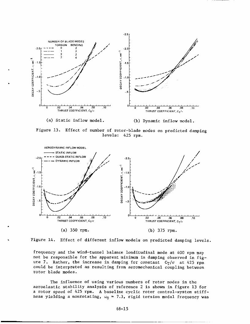
Figure 13. E f f e c t of number of
-2.0 r ---- QUASI-STATIC INFLOW
- -- - DYNAMIC INFLOW
d -1.5 - - -
-
~ " " ' ~ ' I ~ I I " ' ' " ' I ' I I I 0 " " " " " " " " " ' ~ ~ ~ ~ 1
rotor-blade modes on p r e d i c t e d damping levels: 425 rpm.
F igu re 14 . E f f e c t of d i f f e r e n t inf low models on p r e d i c t e d damping levels.
f requency and t h e wind-tunnel balance l o n d i t u d i n a l mode a t 400 rpm may not b e r e s p o n s i b l e f o r t h e apparent minimum i n damping observed i n f i g - u r e 7. Rather , t h e i n c r e a s e i n damping f o r cons t an t CT/O a t 425 rpm could be i n t e r p r e t e d as r e s u l t i n g from aeromechanical coupl ing between r o t o r b l ade modes.
The in f luence of u s i n g var ious numbers of r o t o r modes i n t h e a e r o e l a s t i c s t a b i l i t y a n a l y s i s of r e fe rence 2 i s shown i n f i g u r e 13 f o r a r o t o r speed of 425 rpm. A base l ine c y c l i c r o t o r control-system s t i f f - n e s s y i e l d i n g a nonro ta t ing , we = 7.3, r i g i d t o r s i o n modal f requency w a s
68-15

-2.5-
-2.0 - c
P I I-. -1.5 - z w - 2 - u - u - w 8 -1.0 - t 9 : Y
n - -.5 -
I 0
0 .02 .04 ,013 .08 .10 THRUST COEFFICIENT, CT/U
(c) 400 rpm. (d) 425 rpm.
, Figure 1 4 . Concluded.
-2 0 c
0 z
2 - 1 5 -
0
..
W - U LL
w 8 - 1 0
x n
t a
- 5
0 0 .02 .04 .06 .08 .10
THRUST COEFFICIENT, CT/o
-
~
: \ -
-2.0
r
P * -1.5 6 - I-. z - w ; -1.0
8 - 9 -.5
U w -
t -
w - 0 -
0 -
-
-
-
-
-
/
DYNAMIC INFLOW MODE STATIC INFLOW ( i 2 - u$ --- ($2 + us) -- --
/
0 .02 .04 ,063 .08 .10 THRUST COEFFICIENT, CT/U
Figure 1 5 . P r e d i c t e d damping as a F igu re 16. Regress ing and p rogres s - func t ion of r o t o r r o t a t i o n rate i n g i n p l a n e modal damping wi th and t h r u s t : dynamic in f low d i f f e r e n t aerodynamic in f low model. models: 425 rpm.
used. I n f i g u r e 13a, a s t a t i c i n f low aerodynamic model w a s used , and i n f i g u r e 13b a dynamic in f low aerodynamic model w a s used. R e s u l t s f o r d i f f e r e n t numbers of bending and t o r s i o n r o t o r modes are shown, For the s t a t i c inflow aerodynamic model ( f i g . 13a) and when on ly r o t o r bending is modeled (fundamental f l a p and lead- lag modes), t h e p r e d i c t e d damping exceeds t h e expe r imen ta l ly measured damping d a t a . I n t r o d u c i n g a r i g i d
68-16

c y c l i c t o r s i o n mode reduces damp- ing f o r C ~ l a 5 0.06 and causes a minimum decay c o e f f i c i e n t t o be ob ta ined a t CT/O = 0.012. Inc lud ing t h e f i r s t e l a s t i c t o r - s i o n mode f u r t h e r reduces t h e r e g r e s s i n g i n p l a n e modal damping s i g n i f i c a n t l y . Add i t iona l ly , modeling the second f l a p and lead- lag c y c l i c bending modes is shown t o have l i t t l e i n f l u - ence on t h e p r e d i c t e d r e s u l t s . S i m i l a r r e s u l t s are shown i n f i g u r e 13b f o r t h e a n a l y s i s w i th a dynamic in f low aerodynamic model. I n t h i s case, exc luding a l l t o r s i o n modes shows less damping s e n s i t i v i t y t o increas- i ng t h r u s t f o r t h e p r e d i c t e d decay c o e f f i c i e n t s t han when u s i n g t h e s t a t i c in f low model. When comparing s t a t i c in f low and dynamic in f low r e s u l t s , t h e i n f l u e n c e of dynamic inf low on
- 2 5
- 2 0 r
0 I
5 - 1 5 w u U U
w E - 1 0 -
5 t
w a - 5
0
'"0 -
- 6 3 73 83
- 9 3
-- - --
-
-
-
~ ~ ' ~ ' ~ ~ " " ' ~ ' ' ' ' ' ~ ' ' ' ~ ~ 0 02 04 06 08 10
Figure 1 7 . E f f e c t of r o t o r c y c l i c c o n t r o l system frequency w e on p r e d i c t e d damping levels: 425 rpm, dynamic in f low model.
t h e f l ap- lag b i ade model i s t o reduce t h e p r e d i c t e d decay c o e f f i c i e n t f o r a l l t h r u s t levels. For t h e f u l l f l ap - l ag - to r s ion model, dynamic i n f l o w i n c r e a s e s r o t o r damping f o r CT/O < 0 . 0 5 , but dec reases r o t o r damping f o r h ighe r t h r u s t l e v e l s . I n t h e remaining a n a l y t i c a l r e s u l t s p re sen ted i n t h i s paper , a r o t o r model w i th two e l a s t i c - b l a d e bending modes and two t o r s i o n modes (one r i g i d , one e l a s t i c ) is used .
The in f luence of d i f f e r e n t aerodynamic models i s i l l u s t r a t e d i n f i g u r e 1 4 . R e s u l t s are shown f o r r o t o r speeds of 350, 375, 400, and 425 rpm, wi th a s t a t i c aerodynamic in f low model, a q u a s i - s t a t i c aero- dynamic model, and a dynamic inflow model. Again, a b a s e l i n e c y c l i c r o t o r cont ro l - sys tem nonro ta t ing frequency of we = 7.3 was modeled. The s t a t i c inf low model unde rp red ic t s damping f o r f o r a l l r o t o r r o t a t i o n speeds and o v e r p r e d i c t s damping f o r r o t o r r o t a t i o n speeds except 350 rpm. The q u a s i - s t a t i c i n f low model i s l e s s s e n s i t i v e t o t h r u s t v a r i a t i o n s and g i v e s b e t t e r agreement wi th expe r imen ta l d a t a than t h e s t a t i c in f low model. However, t h i s model s i g n i f i c a n t l y o v e r p r e d i c t s damping f o r CT/G < 0.05. The c o r r e l a t i o n ob ta ined wi th t h e dynamic in f low model is very good, a l though a t h ighe r r o t o r r o t a t i o n a l speeds and t h r u s t c o e f f i c i e n t s , p r e d i c t e d damping l e v e l s exceed measured v a l u e s . With t h e dynamic inf low model, t h e mini- mum damping level f o r 0.01 S C T / O 5 0.02 i s p r e d i c t e d . Although a l l t h r e e a n a l y s e s p r e d i c t s i g n i f i c a n t i n c r e a s e s i n damping a t nega t ive t h r u s t c o n d i t i o n s , i n s u f f i c i e n t experimental d a t a e x i s t t o v e r i f y t h i s t r e n d .
C T / U < 0.05 CT/U > 0.05 f o r a l l
From f i g u r e 1 4 , it is seen t h a t a l l t h r e e aerodynamic models f a i l t o p r e d i c t t h e r educ t ion i n damping a t c o n s t a n t moderate-to-high t h r u s t l e v e l s , CT/O F 0.04 , f o r 350 t o 400 rpm. where t h e p r e d i c t e d r e s u l t s (wi th a dynamic inf low model on ly) as a f u n c t i o n of r o t o r speed and t h r u s t a r e p re sen ted . From t h e s e r e s u l t s ,
Th i s is shown i n f i g u r e 15,
68-1 7

i n c r e a s i n g r o t a t i o n speed a t c o n s t a n t t h r u s t always i n c r e a s e s t h e decay c o e f f i c i e n t . f i g u r e s 7, 12a, and 12b, i t is apparent t h a t minimum damping measured a t 400 rpm i s no t p r e d i c t e d by t h e a n a l y s i s . F u r t h e r s tudy is r e q u i r e d t o determine t h e reason f o r t h i s d i screpancy between p r e d i c t e d and m e a - sured damping t r e n d s .
Comparing wi th t h e c u r v e - f i t exper imenta l r e s u l t s of
A s discussed i n t h e p r e v i o u s s e c t i o n , t h e t es t technique used i n t h i s experiment a l lows f o r d e t e r m i n a t i o n of t h e r e g r e s s i n g i n p l a n e modal c h a r a c t e r i s t i c s . To v a l i d a t e t h i s procedure, c a l c u l a t i o n s were per- formed comparing t h e decay c o e f f i c i e n t s w i t h t h e s t a t i c aerodynamic i n f l o w model and t h e dynamic inf low model f o r bo th t h e r e g r e s s i n g and p r o g r e s s i n g inp lane modes a t 425 rpm ( f i g . 1 6 ) . For t h e s t a t i c inf low model, each mode h a s v i r t u a l l y t h e same decay c o e f f i c i e n t s , because t h e r e i s l i t t l e coupl ing wi th t h e body degrees of freedom, and t h e r e is no unsteady wake model t o couple w i t h i n d i v i d u a l r o t o r modes. Using a dynamic inflow model s i g n i f i c a n t l y reduces t h e i n p l a n e r e g r e s s i n g mode damping, and t h e inp lane p r o g r e s s i n g mode damping is almost i d e n t i c a l t o t h e decay c o e f f i c i e n t s ob ta ined f o r t h e s t a t i c inf low model. Dynamic i n f l o w h a s l i t t l e o r no e f f e c t on t h e p r o g r e s s i n g i n p l a n e mode, a r e s u l t of t h i s inflow model be ing a low-frequency, unsteady aerodynamics r e p r e - s e n t a t i o n . Because of t h e h igh degree of c o r r e l a t i o n between t h e pre- d i c t e d damping f o r t h e r e g r e s s i n g inp lane mode us ing a dynamic i n f l o w model and the exper imenta l d a t a , and because of t h e poor c o r r e l a t i o n between experiment and t h e p r e d i c t e d p r o g r e s s i n g i n p l a n e modal damping, i t i s apparent t h a t t h e test technique d i d s u c c e s s f u l l y a l low f o r d i r e c t measurement of t h e inp lane r e g r e s s i n g mode c h a r a c t e r i s t i c s when o n l y recording d a t a from one b lade . T h i s tes t technique , involv ing i n d i v i d u a l e x c i t a t i o n of i n p l a n e r o t o r modes, w i l l be i n v e s t i g a t e d f u r - t h e r i n f u t u r e f u l l - s c a l e r o t o r dynamic tests.
The inf luence of t h e c y c l i c r o t o r control-system mode on p r e d i c t e d damping levels a t 425 rpm is shown i n f i g u r e 1 7 . A dynamic inf low model i s used f o r t h e a n a l y s i s . Nonrotat ing f r e q u e n c i e s between 6 .3 5 we 5 9 .3 a r e shown. system s t i f f n e s s i s given i n t a b l e 3. The b a s e l i n e v a l u e used i n obta in- i n g t h e resul ts shown i n f i g u r e s 13-16 i s Although t h e c y c l i c control-system s t i f f n e s s h a s only moderate i n f l u e n c e i n reducing damping a t h igh t h r u s t levels , i n c r e a s i n g t h e s t i f f n e s s can i n c r e a s e t h e damping a t low t h r u s t l e v e l s (over 80% f o r t h e minimum damping v a l u e a t
The corresponding r o t o r c y c l i c c o n t r o l -
w e = 7.3.
C,/a = 0.02) . The s a m e t r e n d i s
Table 3 .- Control-system s t i f f n e s s v a r i a t i o n s used i n f i g u r e 17: 425 rpm, Ie = 0.106 kg-m 2
we *e 3 K e 3 l / r e v rad /sec N*m/rad
6 .3 280.4 8 , 300 7.3 324.9 11 , 140 8.3 369.4 14 , 410 9 -3 413.9 18,090
l..
obta ined when us ing a s t a t i c i n f l o w model ( r e f . 8 ) . Because of t h e l a c k of exper imenta l d a t a f o r t h e wind-tunnel test c o n f i g u r a t i o n , a v a l u e of w e = 7.3 w a s s e l e c t e d as t h e b a s e l i n e v a l u e f o r t h e r e s u l t s p r e s e n t e d i n t h i s paper . T h i s r e s u l t s i n a r o t o r test a p p a r a t u s control-system s t i f f n e s s t h a t is approximately t h e s a m e as t h a t of t h e r o t o r when i t i s i n s t a l l e d on a BO-105 f l i g h t a i r c r a f t ; t h e s t i f f - n e s s i s a l s o e q u a l t o t h a t of o t h e r

s i m i l a r r o t o r c o n t r o l systems previous ly t e s t e d on t h e Ames Rotor T e s t Apparatus.
6. FULL-SCALE DATA CORRELATION
The wind-tunnel hover performance d a t a f o r 425-rpm o p e r a t i o n is compared wi th a l i m i t e d amount of a c t u a l f l i g h t - t e s t d a t a (acqui red i n hover ing f l i g h t ) i n f i g u r e 18. Also shown is t h e p r e d i c t e d hover p e r -
0 . ,008
0" I-.
0 5
8 z ,004
2
,006 W
B
,002
formance from t h e modified pre- s c r i b e d wake model ( f i g . 6 ) . The f l i g h t - t e s t d a t a , ob ta ined from an MBB tes t program, is l i m i t e d t o t h e des ign hover t h r u s t con- d i t i o n of approximately CT/O = 0.07. S ince t h e f l i g h t - test d a t a have h ighe r power requi rements t han t h e wind- t u n n e l d a t a , it can be-assumed t h a t t h e a d d i t i o n a l 10% i n r o t o r t h r u s t is, i n p a r t , overcoming t h e aerodynamic download on t h e h e l i c o p t e r f u s e l a g e and o t h e r adve r se aerodynamic i n t e r a c t i o n s .
-
-
-
- -
Although few good-quality s t a b i l i t y d a t a have been pub- l i s h e d f o r f u l l - s c a l e h i n g e l e s s r o t o r systems, d a t a do e x i s t f o r t h e BO-105 r o t o r system t e s t e d on a w h i r l tower ( r e f . 3 ) . These d a t a are compared wi th t h e pres- e n t r e s u l t s i n f i g u r e 19. The damping d a t a have been presented i n terms of pe rcen t c r i t i ca l damping i n t h e r o t a t i n g system. Only 425-rpm whirl-tower d a t a a r e a v a i l a b l e f o r comparison. The whirl-tower d a t a obta ined f o r t he lead- lag motion compare w e l l f o r low r o t o r t h r u s t (CT/O < 0.03). A t moderate r o t o r t h r u s t l e v e l s (0.05 < CT/O < 0.08) , t h e whi r l - tower d a t a i n d i c a t e somewhat h i g h e r damping levels. No d a t a f o r h i g h r o t o r t h r u s t (CT/O > 0.08) are a v a i l a b l e f o r comparison. The p r e d i c t e d damping levels us ing a dynamic inf low model ( f i g . 14d) are a l s o shown.
9 -
z 8 - u -
A 425 rpm 4 FLIGHT TEST - MODIFIED PRESCRIBED WAKE DATA (FIG. 6)
.012 r P
/ DATA (REF. 3)
ANALYSIS WITH DYNAMIC INFLOW
,/' ---
1 ,010 d
A
0 .02 .04 .06 .08 .10 .12 THRUST COEFFICIENT, CT/U
0 ' ' ' ' ' ' ' ' ' 1 1 ' ' ' 1 ' 1 ' ' ' ' 1 ' 1 ' 1
Figure 18. Comparison of wind-tunnel and f l i g h t - t e s t hover performance d a t a .
F igu re 19. Comparison of BO-105 damping d a t a with whirl-tower r e s u l t s .
68-19
8 . COMPARISON WITH BENiINGLESS MAIN ROTOR DATA
. 0
006 V
+- z w 0 :: 004
0 V K
2
w
$ O0*
0
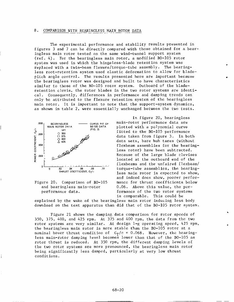
The experimental performance and s t a b i l i t y r e s u l t s presented i n f i g u r e s 3 and 7 can be d i r e c t l y compared wi th those obta ined f o r a bear- i n g l e s s main r o t o r t e s t e d on t h e same wind-tunnel support system ( r e f . 4 ) . For t h e b e a r i n g l e s s main r o t o r , a modified BO-105 r o t o r system w a s used i n which t h e h inge less -b lade r e t e n t i o n system w a s r e p l a c e d with a twin-beam f lexure / torque- tube assembly. l e s s r o o t - r e t e n t i o n system used e l a s t i c deformation t o a l l o w f o r blade- p i t c h a n g l e c o n t r o l . The r e s u l t s presented h e r e are important because t h e b e a r i n g l e s s r o t o r w a s designed and b u i l t t o have c h a r a c t e r i s t i c s s i m i l a r t o those of t h e BO-105 r o t o r system. Outboard of t h e blade- r e t e n t i o n c l e v i s , t h e r o t o r b l a d e s i n t h e two r o t o r systems a r e i d e n t i - c a l . Consequently, d i f f e r e n c e s i n performance and damping t r e n d s can only be a t t r i b u t e d t o t h e f l e x u r e r e t e n t i o n system of t h e b e a r i n g l e s s main r o t o r . I t i s important t o n o t e t h a t t h e support-system dynamics, as shown i n t a b l e 2, w e r e e s s e n t i a l l y unchanged between t h e two tests.
The bear ing-
MAIN ROTOR DATA BO105 DATA p l o t t e d wi th a polynomial curve (FIG 31
f i t t e d t o t h e BO-105 performance d a t a taken from f i g u r e 3 . I n both d a t a se ts , b a r e hub ta res (without flexbeam assembl ies f o r t h e bear ing- less r o t o r ) have been s u b t r a c t e d . Because of t h e l a r g e b l a d e c l e v i s e s l o c a t e d a t t h e outboard end of t h e flexbeams and t h e u n f a i r e d flexbeam/
rpm - 0 350
I
' 1 1 1 / 1 1 1 1 1 / ' 1 ' 1 1 1 1 1 ' 1 1 1 1
L
Figure 21 shows t h e damping d a t a comparison f o r r o t o r speeds of 350, 375, 400, and 425 rpm. A t 375 and 400 rpm, t h e d a t a from t h e two r o t o r systems are very s imi l a r . A t d e s i g n 1-g o p e r a t i n g speed, 425 rpm, t h e b e a r i n g l e s s main r o t o r i s more s t a b l e than t h e BO-105 r o t o r a t a nominal hover t h r u s t c o n d i t i o n of less main-rotor damping level becomes lower than t h a t of t h e BO-105 as r o t o r t h r u s t is reduced. A t 350 rpm, t h e d i f f e r e n t damping levels of t h e two r o t o r systems are more pronounced, t h e b e a r i n g l e s s main r o t o r be ing s i g n i f i c a n t l y less damped, p a r t i c u l a r l y a t v e r y low t h r u s t c o n d i t i o n s .
CT/a = 0.068. However, t h e bear ing-
68-20

0 BEARINGLESS MAIN ROTOR
Y d
-1.5- i!
8 -1.0
0 U U W
DATA (REF. 4)
-2.0 F
-
r
< -1.5 c
I-*
'i 0 -1.0-
8 s -.5
U U W
t
W - n
0 0
-
-
-
O' ' 6 ' ' '.02 ' ' '.& ' ' '.& ' ' '.Os' ' ' . ; o ' ' THRUST COEFFICIENT, CT/o
(a) 350 rpm.
-"ol p -1.5
0
a
O' ' i ' ' . d 2 ' ' ' .oz ' ' . f f i ' ' ' .d*' ' ' , i o ' ' THRUST COEFFICIENT, C ~ l a
( c ) 400 rpm.
0
0 .02 .04 .06 .08 .10 THRUST COEFFICIENT, CT/u
(b) 375 rpm. -2.5r
c -2.01
0
0
0
0
0
0 0 .02 .04 .06 .08 .10
THRUST COEFFICIENT, C ~ l u
(d) 425 rpm.
F igu re 21. Comparison of BO-105 and b e a r i n g l e s s main-rotor damping d a t a .
9. CONCLUSIONS
A f u l l - s c a l e , BO-105 h e l i c o p t e r h inge le s s - ro to r system w a s t e s t e d i n hover . Performance and damping of t h e r e g r e s s i n g inp lane r o t o r mode w a s determined f o r t r e n d s wi th changing r o t o r t h r u s t and t i p speed. These exper imenta l d a t a have been compared wi th a n a l y t i c a l p r e d i c t i o n s and o t h e r hover d a t a , Direct comparison between r e s u l t s f o r a bear ing- less main-rotor system and t h e BO-105 r o t o r are presented . f i n d i n g s of t h i s s tudy are as fol lows:
The major
68-21

1. BO-105 rotor-system damping v a r i e s wi th r o t o r t h r u s t a t con- s t a n t r o t a t i o n a l speed. CT/U of about 0.02. i s least s t a b l e a t 400 rpm.
A minimum damping level i s obta ined a t a A t c o n s t a n t t h r u s t (CT/U 2 0.02) , t h e r o t o r system
2 . Experimental damping d a t a s c a t t e r , a l though s i g n i f i c a n t f o r h i g h l y damped r o t o r o p e r a t i n g c o n d i t i o n s , d i d no t l i m i t t h e determina- t i o n of damping t r e n d s wi th vary ing r o t o r r o t a t i o n speed a t c o n s t a n t t h r u s t .
3. Predic ted aerodynamic performance u s i n g a modif ied p r e s c r i b e d wake model f o r t h e l o c a t i o n of t h e t i p v o r t i c e s i n t h e f a r wake ade- q u a t e l y p r e d i c t e d r o t o r power and f i g u r e of m e r i t as f u n c t i o n s of t h r u s t .
4 . Damping t r e n d s a t cons tan t r o t o r speed are w e l l p r e d i c t e d wi th a comprehensive r o t o r c r a f t a n a l y s i s . r e s u l t s were n o t s e n s i t i v e t o t h e number of support-system modes mod- e l e d , t h e f i r s t two e l a s t i c - b l a d e bending modes and t h e f i r s t r i g i d - b l a d e and e l a s t i c - b l a d e t o r s i o n modes of t h e b l a d e s were r e q u i r e d f o r adequate c o r r e l a t i o n .
Although t h e p r e d i c t e d
5 . Nei ther minimum damping l e v e l s nor damping t r e n d s w i t h vary- i n g t h r u s t a t cons tan t r o t a t i o n speed f o r t h e r e g r e s s i n g i n p l a n e mode are a c c u r a t e l y p r e d i c t e d u s i n g a s t a t i c o r a q u a s i - s t a t i c in f low model. A dynamic inf low model s i g n i f i c a n t l y improves t h e c o r r e l a t i o n between p r e d i c t e d and experimental performance a t a l l t h r u s t c o n d i t i o n s . How- ever, r e d u c t i o n i n damping a t moderate c o n s t a n t - t h r u s t c o n d i t i o n s when i n c r e a s i n g r o t o r r o t a t i o n speed from 350 t o 400 rpm i s n o t p r e d i c t e d wi th any aerodynamic model.
6 . S t a b i l i t y d a t a obta ined a t 425 rpm compare w e l l w i t h whi r l - tower d a t a f o r low t h r u s t levels . However, t h e r e are no whirl-tower d a t a wi th which t o compare d a t a obta ined a t h igh t h r u s t levels .
7. I n comparing BO-105 damping d a t a d i r e c t l y wi th d a t a from a b e a r i n g l e s s main r o t o r system, t r e n d s a t cons tan t r o t a t i o n a l speed w i t h vary ing t h r u s t a r e s imi l a r . However, d e s p i t e be ing more s t a b l e a t d e s i g n hovering c o n d i t i o n s (425 rpm, C T / U = 0.068), t h e b e a r i n g l e s s main r o t o r inplane o p e r a t i o n i s s i g n i f i c a n t l y less damped t h a n i s t h e BO-105 r o t o r system.
REFERENCES
1. Peterson , R . L . ; and Warmbrodt, W . : Hover T e s t of a Ful l -Scale Hingeless H e l i c o p t e r Rotor: A e r o e l a s t i c S t a b i l i t y , Performance and Loads Data. NASA TM-85892, 1984.
2 . Johnson, W . : A Comprehensive A n a l y t i c a l Model of R o t o r c r a f t Aero- dynamics and Dynamics. NASA TM-81182, 1980.
3. Kloppel, V . ; Kampa, K . ; and I s s e l h o r s t , B . : Aeromechanical Aspects i n the Design of Hingeless /Bear ingless Rotor Systems. No. 57, Ninth European R o t o r c r a f t Forum, Stresa, I t a l y , Sept . 1983.
Paper
68-22
4 . Warmbrodt, W . ; and McCloud, J . L. : A Fu l l - sca l e Wind Tunnel I n v e s t i g a t i o n of a Hel icopter Bea r ing le s s Main Rotor . NASA TM-81321, 1981.
5. S t a l e y , J. A . : Val ida t ion of Ro to rc ra f t F l i g h t S imula t ion Program through C o r r e l a t i o n with F l igh t Data f o r S o f t In-Plane Hingeless Rotors . USAAMRDL TR-75-50, J an . 1976.
6 . Landgrebe, Anton J . : The Wake Geometry of a Hovering He l i cop te r Rotor and Its In f luence on Rotor Performance. J . h e r . He l i cop te r SOC., v o l . 1 7 , no. 4, Oct . 1972.
7. Kocurek, J. David; and Tangler , James L.: A Presc r ibed Wake L i f t i n g Surface Hover Performance Analysis . J . h e r . He l i cop te r SOC., v o l . 22, no. 1, Jan. 1977.
8 . Pe te r son , R . L . ; Warmbrodt, W . ; and Hoover, J.: Aeromechanical S t a b i l i t y of a Fu l l - sca l e Hingeless Rotor i n Hover. Paper No. A-84-40-62-3000, 40th Annual Na t iona l Forum a t t h e American He l i cop te r Soc ie ty , Arl ington, V a . , May 1984.

1. Report No. I 2. Government Accession No. I 3. Recipient's catalog NO.
7. Author(sJ
William Warmbrodt and Randall L. Peterson
9. Performing Organization Name and Address
NASA TM-85990 4. Title and Subtitle I 5. Report Date
I I
8. Performing Organization Report No.
A-9827 10. Work Unit No T-3504
HOVER TEST OF A FULL-SCALE HINGELESS ROTOR
I2 Sponsoring Agency Name and Address
13. Type of Report and Per~od Covered
Technical Memorandum
Ames Research Center Moffett Field, CA 94035
National Aeronautics and Space Administration Washington, DC 20546
1 1 . Contract or Grant No.
14. Sponsoring Agency Code 532-06-11
16 Abstract
The performance and aeroelastic stability in hover of a 9.8-m diameter, hingeless helicopter rotor system was evaluated. inplane damping data were obtained for rotor operation between 350 and 425 rpm for thrust coefficients (C,/o) between 0.0 and 0.12. thrust, a minimum in rotor inplane damping was measured at 400 rpm; the effect of experimental data scatter on this damping trend was determined to be insig- nificant. Good agreement is shown between experimental performance data and performance predicted by a comprehensive computer code. The influence of different aerodynamic inflow models on predicting damping levels is also shown. The best correlation with experimental stability data was obtained when a dynamic inflow model was used instead of static or quasi-static inflow models. Comparison with other full-scale, hingeless rotor data in hover is presented. Direct comparisons were also made between the hingeless rotor data and data from a full-scale, bearingless main rotor test performed on the same general-purpose test apparatus. The aerodynamic efficiency of the bearingless rotor was less at low thrust conditions, but was the same at design thrust. Although the bearingless rotor was more highly damped at design tip speed and 1-g thrust operation, greater sensitivity to operating conditions was shown. At low thrust levels the bearingless main rotor was less damped than the hingeless rotor.
Rotor performance and
At constant rotor
17. Key Words (Suggested by Author(sJ) I 18. Distribution Statement
Helicopters Rotary wing Rotor aerodynamics Ground resonance
Unlimited
Subject Category - 05
21. No. of Pages 22. Rice' I A02 I 23 19. Security Classif. (of this report) 20. Security Classif. (of this page1
Unclassified Unclassified
'For sale by the National Technical Information Service, Springfield, Virginia 22161