Hot Air Recirculation by Air Coolersfiles.chartindustries.com/hudson/Hot-Air-Recirculation.pdf ·...
24
Hot Air Recirculation by Air Coolers A.Y. Gunter and K.V. Shipes Hudson Products Corporation, Houston, Texas Written discussion on this paper will be accepted at the AIChE Heat Transfer and Energy Conversion Division, 345 East 47 Street, New York, New York 10017, until October 1, 1971. Presented at the Twelfth National Heat Transfer Conference AIChE – ASME Tulsa, Oklahoma August 15-18, 1971 Preprinted for the conference by American Institute of Chemical Engineers 345 East 47 Street, New York, New York 10017 Preprinting this paper does not release it for publication. All rights are reserved by the sponsoring society.
Transcript of Hot Air Recirculation by Air Coolersfiles.chartindustries.com/hudson/Hot-Air-Recirculation.pdf ·...

Hot Air Recirculation by Air Coolers
A.Y. Gunter and K.V. ShipesHudson Products Corporation, Houston, Texas
Written discussion on this paper will be accepted at the AIChE Heat Transfer and EnergyConversion Division, 345 East 47 Street, New York, New York 10017, until October 1, 1971.
Presented at the
Twelfth National Heat Transfer ConferenceAIChE – ASME
Tulsa, OklahomaAugust 15-18, 1971
Preprinted for the conference by
American Institute of Chemical Engineers345 East 47 Street, New York, New York 10017
Preprinting this paper does not release it for publication.All rights are reserved by the sponsoring society.

Hudson Products Corporation Page 2 of 24Houston, Texas Hot Air Recirculation by Air Coolers
HOT AIR RECIRCULATION BY AIR COOLERS
A.Y. Gunter, Consulting Engineer K.V. Shipes, Senior Research & Development EngineerHudson Products Corporation Hudson Products CorporationHouston, Texas Houston, TexasMember of ASME Member of ASME
Presented at the Twelfth National Heat Transfer Conference, AIChE-ASMETulsa, Oklahoma, August 15-18, 1971
ABSTRACT
This paper covers model, plant and field smoke testing on dry air coolers. A techniqueand equipment for smoke testing is described. From this qualitative and quantitativedata, preliminary equations are outlined for determining if an air cooler design willrecirculate hot air. Numerous examples of correct and incorrect air cooler layouts areshown for the engineer's consideration.
HOT AIR RECIRCULATION BY AIR COOLERS
I. HISTORY
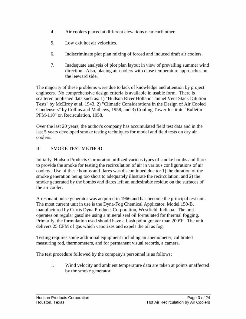
Commercial dry air cooling dates back to 1930. The first designs were single facevertical tubes, with fan in the vertical plane forcing air through the bundle (Figure 1a).Later, square or rectangular units with vertical tube bundles were made (Figure 1b).These designs were soon in disfavor due to wind direction effects. About 1935, unitswith horizontal fin tubes of induced draft (Figure 1c) and forced draft (Figure 1d) typeswere in operation. Before 1940, to save plot plan area, "V" type units were designed.These are shown in Figure 1e (forced draft) and Figure 1f (induced draft). They have theinherent problem of wind direction, requiring wind screens and close attention to hot airrecirculation. By 1950, 90 to 100 percent commercial dry air-cooled process plants werebuilt. All during this period the problem of hot exit air recirculation to inlets was notedand various solutions used.
There is a large amount of published information available covering wind effects onbuildings of various shapes, and dilution of vent air from vehicular tunnels. Only a smallamount of published material is available on air coolers. The bibliography attachedcontains only a small proportion of the literature extant. Briefly, the most prevalent hotair recirculation problems encountered in the last 35 years were:
1. High air approach velocities to air coolers.
2. Air coolers placed too close to each other in the downwind direction.
3. Air coolers placed in front of downwind obstructions.
Hudson Products Corporation Page 3 of 24Houston, Texas Hot Air Recirculation by Air Coolers
4. Air coolers placed at different elevations near each other.
5. Low exit hot air velocities.
6. Indiscriminate plot plan mixing of forced and induced draft air coolers.
7. Inadequate analysis of plot plan layout in view of prevailing summer winddirection. Also, placing air coolers with close temperature approaches onthe leeward side.
The majority of these problems were due to lack of knowledge and attention by projectengineers. No comprehensive design criteria is available in usable form. There isscattered published data such as: 1) "Hudson River Holland Tunnel Vent Stack DilutionTests" by McElroy et al, 1943, 2) "Climatic Considerations in the Design of Air CooledCondensers" by Collins and Mathews, 1958, and 3) Cooling Tower Institute "BulletinPFM-110" on Recirculation, 1958.
Over the last 20 years, the author's company has accumulated field test data and in thelast 5 years developed smoke testing techniques for model and field tests on dry aircoolers.
II. SMOKE TEST METHOD
Initially, Hudson Products Corporation utilized various types of smoke bombs and flaresto provide the smoke for testing the recirculation of air in various configurations of aircoolers. Use of these bombs and flares was discontinued due to: 1) the duration of thesmoke generation being too short to adequately illustrate the recirculation, and 2) thesmoke generated by the bombs and flares left an undesirable residue on the surfaces ofthe air cooler.
A resonant pulse generator was acquired in 1966 and has become the principal test unit.The most current unit in use is the Dyna-Fog Chemical Applicator, Model 150-B,manufactured by Curtis Dyna Products Corporation, Westfield, Indiana. The unitoperates on regular gasoline using a mineral seal oil formulated for thermal fogging.Primarily, the formulation used should have a flash point greater than 200°F. The unitdelivers 25 CFM of gas which vaporizes and expels the oil as fog.
Testing requires some additional equipment including an anemometer, calibratedmeasuring rod, thermometers, and for permanent visual records, a camera.
The test procedure followed by the company's personnel is as follows:
1. Wind velocity and ambient temperature data are taken at points unaffectedby the smoke generator.

Hudson Products Corporation Page 4 of 24Houston, Texas Hot Air Recirculation by Air Coolers
2. Positioning the generator so that the full quantity of smoke generated isdrawn into the air inlet, exit air temperatures are taken and an exit airtraverse is made.
3. Inlet air temperatures around the perimeter of the air cooler are taken withthe generator in operation.
4. Inlet area, for approach velocity, measurements are made with thecalibrated rod.
5. Photographs are taken for visual record of plume heights and testconditions.
III. THEORY
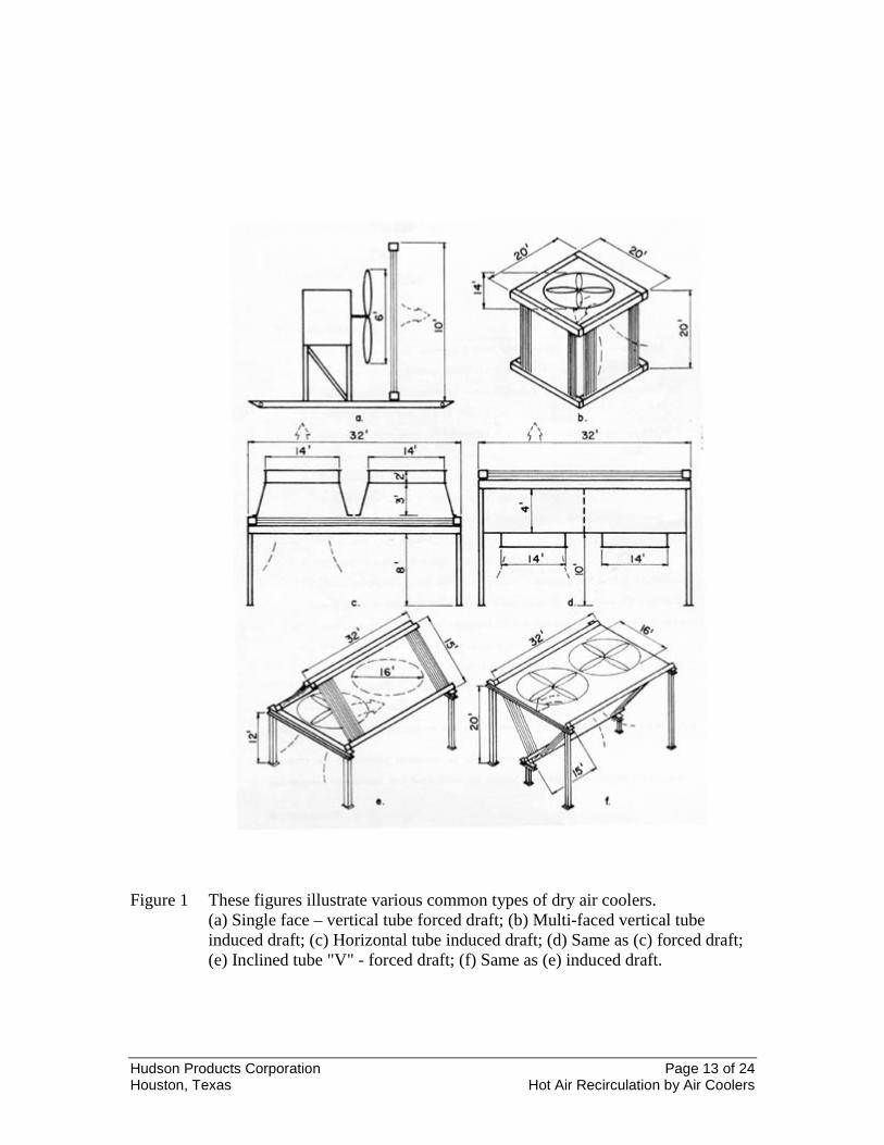
Figure 2 shows scale model tests at 5 and 15 miles per hour wind velocity for forced andinduced draft units. These test data agree very closely with McElroy et al (1) their Figure16, based on Ve/Vw ratios. Figures 3A and 3B show field tests on both induced andforced draft air coolers in a southwestern plant at 5 miles per hour wind velocity. TheVe/Vw velocity ratios were 3.1 and 1.1, respectively. The approach velocities were 8.3and 13.3 feet per second. Thus, it is seen that Ve/Vw and Ve/Va ratios are primaryfactors in air flow around air coolers.
The type of wind is important. With a steady wind, stable conditions usually prevailaround the air coolers. Gusty, rolling turbulent winds cause unstable conditions and arenot amenable to accurate prediction.
For a single air cooler, such as shown in Figure 4 Unit A, under no wind (Vw = 0), hot airrecirculation is determined by:
(1)
With steady wind the equation becomes:
(2)
Note: ∅ = C
gwVw
2
2ρ Negative pressure on downwind side of air cooler.
C = 0.2 to 0.6
For an air cooler as shown in Figure 4, Unit B, downwind from Unit A, under steadywind, hot air recirculation is determined by three factors; namely,
ionrecirculatNegativeionrecirculatnoPositive
g
aVa
g
eVe−
−=
−
22
22 ρρ
ionrecirculatNegativeionrecirculatnoPositive
g
aVa
g
eVe−
−=
+
−
22
22φ
ρρ

Hudson Products Corporation Page 5 of 24Houston, Texas Hot Air Recirculation by Air Coolers
1. Forces around Unit A2. Forces around Unit B3. Dilution of hot exit gases from Unit A
For the forces around Units A and B, Figure 4, the equations are:
ionrecirculatNegativeionrecirculatnoPositive
g
dVd
g
aVa
g
eVe
)A()A(−
−=
+
+
−
222
222φ
ρρρ(3)
ionrecirculatNegativeionrecirculatnoPositive
gdVd
gaVa
geVe
)B()B(−
−=
+
+
−
222
222φρρρ (4)
Note: If either equation 3 or 4 is negative there will be hot air recirculation.
For diluation effects on Unit B from Unit A, Figures 5 [from McElroy et al (1)] givesapproximate intensity. Since, in this case, the units are equal heights the plot cannot beread. Assume Unit B is 10 feet higher, Ve = 20, Va = 10, Vw = 22, diameter of fans =12, L = 60. Then Ve/Vw = 0.91, L/fan diameter = 5.0, vertical distance/fan diameter =0.83. From Figure 5 dilution is between 10 to 15 percent. If ambient air is 90°F, and airrise is 40°F, then mixed air to Unit B would be 94 to 95°F. Figure 6 from the CoolingTower Institute "Bulletin PFM-110", 1958, plots percent recirculation versus towerlength in feet. This varies from 1 to 11 percent and is not comparable to dry air coolersexcept where in banks and free area under banks is 50 percent or more obstructed. Thedata reported is on thirty different cooling towers and was also plotted against frameheight, exit velocity, stack height, wind direction and velocity. No correlation was betterthan that shown in Figure 6.
One final point should be made. Theoretically, the hot exit gases should have a thermaldraft effect. Field and model tests do not show any appreciable difference in tests up to70°F air temperature rise. This is probably due to the fact that the exit air velocity isalways much greater than the velocity which would occur due to thermal draft alone. Theauthors, therefore, have ignored this effect.
IV. DISCUSSION OF RESULTS
This paper presents various qualitative plus some quantitative field test data from whichpreliminary equations have been proposed. Additional field data, under rigorous testconditions, is required for complete quantitative analysis. Discussion of results coverstesting the present data by the proposed equations.
This test, Figure 3A, was run in a recycling plant in the southwest. Several forced draftunits, 13 x 24, each having two 10-ft diameter fans, were being used to cool jacket water.The test conditions were:

Hudson Products Corporation Page 6 of 24Houston, Texas Hot Air Recirculation by Air Coolers
.067e 27 == ρ.Ve
.071a 8 == ρVa
.071w 8 == ρVw
+
−
gwVw.
gaVa
geVe
220
22
222 ρρρ
( ) ( ) ( )64
0718 2064
071864
06727 222 ..... −−=
0310014071054 .... −=−−=
The test equation indicates self-recirculation, and this is borne out by Figure 3A.Reduction of cooling capacity up to 11 percent was observed.
This test, Figure 3B, was run in the same recycling plant as the previous case; however, itwas run on an induced draft unit, 14 x 24, with two 10-ft diameter fans.
The test conditions were:
.067e 28 == ρVe
.071a 7 == ρVa
.071w 8 == ρVw
+
−
gwVw.
gaVa
geVe
220
22
222 ρρρ
( ) ( ) ( )64
0718 2064
071764
06728 222 .... −−=
7530014054821 .... =−−=
The test equation indicates no possibility of self-recirculation, which is borne out byFigure 3B.
This test, Figure 7, was run in Hudson's plant on a forced draft unit (20-32), having two14-ft diameter fans. By suspending the unit (while running) at four different heights, andsmoke testing at each height, it was possible to gauge the effect of varying only theapproach velocity. The test conditions were: Ve = 8.1, Vw = 7.0, and Va = 6.1, 6.4, 7.5and 8.8, respectively in figures A, B, C and D. There was no heat load and the ambienttemperature was 71°. Therefore, ρe = ρa = ρw = .075.

Hudson Products Corporation Page 7 of 24Houston, Texas Hot Air Recirculation by Air Coolers
Referring to figure A:
[ ] ( ) ( ) ( )[ ] 0220720161864075
202
222222 .....
Vw.VaVeg
=−−=−−ρ
figure B:
( ) ( ) ( )[ ] 0170720461864075 222 ....
.=−−
figure C:
( ) ( ) ( )[ ] 0002720571864075 222 ..... −=−−
figure D:
( ) ( ) ( )[ ] 0250720881864075 222 ..... −=−−−
These results indicate that figures A and B are not self-recirculating; that figure C is righton the line; and that figure D is self-recirculating. These results agree with thecorresponding pictures in all four cases.
This test, Figure 8, was run in a Gulf Coast refinery. Two long banks of forced draftunits were involved. These banks were about 80 feet apart, as shown in Figure 10. Thetest conditions were:
.066e 57 == ρ.Ve
.070a 06 == ρ.Va
.070d 03 == ρ.Vd
.072w 512 == ρ.Vw
++−
g
wVw.
g
dVd
g
aVa
g
eVe
2
20
222
2222 ρρρρ
( ) ( ) ( ) ( )64
072512 2064
070364
070664
06657 2222 ....... −−−=
02640351010003940580 ..... −=−−−=

Hudson Products Corporation Page 8 of 24Houston, Texas Hot Air Recirculation by Air Coolers
The test equation indicates that the downwind bank will receive hot air from the exit ofthe upwind bank. The test data indicated that this did happen, and that the percentage ofair so recirculating was more than 25 percent of the air to the downwind bank. Thisreduced the capacity of the downwind unit 26 percent and the overall capacity 13 percent.
Figure 9 covers field tests at a southwestern recycling plant. It illustrates plot plan layoutwhere effects of prevailing hot winds were not considered. The plot plan could havebeen revolved 180° at no extra cost and all hot air recirculation problems eliminated.
Data on a test with southwest winds gave 13.6 percent hot exit air recirculation fromsouthwest air coolers to central induced draft inlet air. This raised air inlet temperature 5to 7°F and reduced capacity approximately 10 percent. Essential test data: Ambient air =95°F; elevation = 2600 feet; Vw - SW = 16. Southwest forced draft unit - Va = 7.8; Ve =12.2; ρa = 0.064; ρe = 0.0595. Central induced draft unit - Va = 10.4; Ve = 29.4; ρa =0.064; ρe = 0.0595, Vd = 5.0.
Now, testing southwest air cooler by equation (3):
( ) 22222
lbs/ft 001464
064162
6406405
6406487
640595212
..
....... +=
×+×+×−×
This indicates the southwest bank of air coolers is near hot air recirculation on itself ondownwind side. During the test, occasional puffs of hot air were noted at ground level bythe author. Note that if a C value of 0.3 had been used, equation (3) would have given anegative answer.
Now, equation (4) for central induced draft unit gives:
22222
lbs/ft 61964
0641620
6406405
64064410
640595429
..
....... +=
×+×+×−×
This is well above the recirculation point and C could be the maximum (0.6) withoutcausing recirculation. Here, it is appropriate to point out that induced draft units, with Ve= 20 - 28 fps versus forced draft Ve = 9 - 12 fps, will always have less hot airrecirculation than forced draft.
In this test, hot air recirculation was from the southwest coolers exit into the inlet of thecentral induced draft units, which were one foot higher elevation than exit of thesouthwest units. Refer to Figure 5, which is correlation of stack dilution taken fromMcElroy et al (1). From layout and test data Vw/Ve = 1.3; X/W = 1.5; Y/W = 0.11 thendilution is between 10 and 15 percent. Now, there are 880,000 scfm of 45°F aboveambient air temperature from the southwest unit. 1,280,000 scfm of air is drawn throughthe west inlet of the central induced draft unit which is raised 5°F. This calculates 13.6percent recirculation, based on Figure 5.

Hudson Products Corporation Page 9 of 24Houston, Texas Hot Air Recirculation by Air Coolers
Some ten other tests were run with wind from the south and southeast, all confirmingrecirculation on the induced draft unit. They are not reported here due to effects ofobstructions.
Figure 10 is an end elevation of a bank of air coolers in a natural gasoline plant in thesouthwest. This illustrates the problem of adding a unit to an existing bank of coolers.The new induced draft unit was installed as shown.
Field test data in 3 foot space between old and new units gave: ambient air = 83.5°F;mixed air = 100°F; elevation = 100 ft; Ve old unit = 9.5 (ρair = .065); Vd between units =13.5; Ve new unit = 23.4 (ρair = .065); Va - old = 8.4; Va - new = 8.4. This gives 24percent hot air recirculation and approximately 35 percent reduction in cooling capacityof new unit. If new unit had been placed joining old units, and air inlets at the samelevel, this problem would have been avoided.
Figure 11 is the end elevation of an overhead air-cooled condenser and a bottoms coolerinstalled at different elevations in a Canadian refinery. Prevailing hot winds recirculatednearly all of the bottoms cooler exit gases (Ve) to the overhead condenser.
Figure 12 refers to two banks of forced draft units in an Alaskan plant. These units were18 x 30, each having two 12-ft diameter fans. These units have a relatively high airapproach velocity due to the air access area being limited to approximately 50 percent ofthe bundle face area. Test conditions were:
.070e 39 == ρ.Ve
.076a 517 == ρ.Va
.076w 012 == ρ.Vw
( ) ( ) ( )3050034364094
640761220
64076517
6407039 222
.......... −=−−=−−
The test equation indicates considerable self-recirculation, which was borne out by testdata.
Figure 13 illustrates some installations of jacket water coolers on gas pipeline stations.When wind direction is across coolers to compressor building the hot air recirculatesback from the building to the air coolers. Assume following data: Induced draft - 12-ftdiameter fans; Ve = 25; Vd = 4.2; Va = 8; Vw = 14.7; ρe -.066; ρd and ρa = .071.
Thus, equation (3);
( ) ( ) ( ) ( )506
640717142
6407124
640718
6406625 2222
........
+=×
−×
−×
−×

Hudson Products Corporation Page 10 of 24Houston, Texas Hot Air Recirculation by Air Coolers
There is no recirculation.
Now referring to Figure 5, X/W = 3; Y/W = 3.7; Vw/Ve = 0.59. This shows 50 percentof hot exit air is trapped by compressor building and a substantial percent is returned tothe air cooler. This has been checked in the field and substantiated. Obviously, a forceddraft unit would have a lower hot exit gas trajectory and a larger percent recirculation.
There is another problem with this type of layout. When wind is from over the building,a low pressure turbulent zone is built up between the air cooler and the building whichwill cause hot air recirculation, especially on forced draft units.
V. CONCLUSIONS
1. The four equations presented here are reasonable tests for design engineersto determine possibility of hot air recirculation.
2. Additional field test data under rigorous conditions are needed for refiningequations (1) to (4).
3. The smoke test described here is a useful visual tool for analysis of hot airrecirculation problems.
4. Forced draft air coolers are more susceptible to recirculation than induceddraft due to low exist velocities (Ve).
5. Detailed study of the effects of obstructions and turbulent wind conditionsare needed.
6. Figure 14 presents known correct layout criteria.
7. Using reasonable care and the equations herein, air-cooled installationsmay be economically designed to substantially eliminate air recirculation,as is true of the majority of the installations operating today.
8. Data showing effect on ∅ when wind velocity, Vw, approaches andexeeds Ve is needed to establish proper value of the constant C at variousVe/Vw ratios.

Hudson Products Corporation Page 11 of 24Houston, Texas Hot Air Recirculation by Air Coolers
NOMENCLATURE
C = Constant in equation for ∅ (Value variesfrom 0.2 to 0.6)
Cd = Concentration of Contaminant along axis ofDischarge Stream – See Figure 5
Cs = Concentration Ratio – See Figure 5
Vw = Wind Velocity ft/sec
Ve = Exit Velocity Based on fan throat free area for induced
draft and total fin tube bundle face areafor forced draft air coolers – See Figure 4
ft/sec
Va = Approach VelocityBased on periphery of air cooler andunobstructed height above ground level –See Figure 4
ft/sec
Vd = Downward Velocity Between Two AirCoolers
Based on horizontal plane area betweentwo air coolers and amount of air to theaffected peripheries of the two air cooler– See Figure
ft/sec
X = Horizontal Distance for Air Cooler ft
Y = Vertical Distance Between Air Cooler Exitand Next Inlet
ft
∅=
2g
wVw 2ρLow pressure area downwind
lbs/ft2
ρw, ρe, ρa = Air density, lbs/ft3 referred to wind, exit air,and approaching air
ACKNOWLEDGMENT
The authors appreciate the permission of Hudson Products Corporation to publish thedate and techniques presented in this paper.
Further acknowledgment is due to al the personnel of Hudson Products Corporation whoworked on this project.

Hudson Products Corporation Page 12 of 24Houston, Texas Hot Air Recirculation by Air Coolers
BIBLIOGRAPHY
1. McElroy, G.E.; Brown, C.E.; Gerger, L.E.; and Schrink, H.H.: "Dilution of StackEffluents"; U.S. Department of Interior, Bureau of Mines, Technical Paper 657,1944.
2. Collins, G.F. and Mathews, R.T.: "Climatic Considerations in Design of Air-Cooled Heat Exchangers". Paper 59-A-255, December 4, 1959, annual meetingASME.
3. Cooling Tower Institute Technical Subcommittee No. 2: "Recirculation", CTIbulletin PFM-110, 1958. Also PFM-110A, Appendix to PFM-110.
4. Schmidt, W.: "Calculation of Distribution of Smoke and Waste Gases in theAtmosphere". Gesundheits - Ing. Vol. 49, 1926, pp. 425-426.
5. Sutton, O.G.: "A Theory of Eddy Diffusion in the Atmosphere". Proc. Roy.Society (London) Ser. A Vol. 135, 1932, pp. 143-165.
6. Bailey, A. and Vincent, N.D.G.: "Wind Pressure on Building Including Effectson Adjacent Building". Journal Institute Civil Engineer, March, 1943, pp. 243-275.
7. Dryden, H.L.; Hill, G.C.: "Wind Pressures on Structures". Scientific Papers ofBureau of Standards, Vol. 20, 1926, p. 697.
8. Holdridge, E.S.; Reed, B.H.: "Pressure Distribution on Buildings", Department ofArmy, Contract No. DA-18-064 CML77. August, 1956. Texas EngineeringExperiment Station. Texas A&M.
9. Same as above - Report No. 2.
Hudson Products Corporation Page 13 of 24Houston, Texas Hot Air Recirculation by Air Coolers
Figure 1 These figures illustrate various common types of dry air coolers.(a) Single face – vertical tube forced draft; (b) Multi-faced vertical tubeinduced draft; (c) Horizontal tube induced draft; (d) Same as (c) forced draft;(e) Inclined tube "V" - forced draft; (f) Same as (e) induced draft.
Hudson Products Corporation Page 14 of 24Houston, Texas Hot Air Recirculation by Air Coolers
Figure 2 Comparison of forced and induced draft exit air conditions at 5-15 mph windvelocity; unit conditions: 600 fpm face velocity - 85° air in - 115° air out,45% fan coverage, 52% bundle net free area - scale: 0.82" = 1' - 0"; Modelrepresents half of 14' x 36' unit.

Hudson Products Corporation Page 15 of 24Houston, Texas Hot Air Recirculation by Air Coolers
HUDSON PRODUCTS CORPORATION
Figure 3A Field test smoke pictures of forced draft air cooler at a southwesternrecycling plant

Hudson Products Corporation Page 16 of 24Houston, Texas Hot Air Recirculation by Air Coolers
HUDSON PRODUCTS CORPORATION
Figure 3B Field test smoke pictures at same plant as 3A on induced draft air coolers.

Hudson Products Corporation Page 17 of 24Houston, Texas Hot Air Recirculation by Air Coolers
Figure 4 Force diagram and nomenclature for induced or forced draft air coolers.
Figure 5 Maximum relative gas concentrations in undisturbed streams in the vicinityof a stack.

Hudson Products Corporation Page 18 of 24Houston, Texas Hot Air Recirculation by Air Coolers
Figure 6 Maximum percent recirculation versus cooling tower length. Induced draftcooling towers only.
Figure 7A Smoke test on suspended air cooler at Va = 6.1 and Ve = 8.1, norecirculation.
Figure 7B Smoke test on suspended air cooler at Va = 6.4 and Ve = 8.1, norecirculation.

Hudson Products Corporation Page 19 of 24Houston, Texas Hot Air Recirculation by Air Coolers
Figure 7C Smoke test on suspended air cooler at Va = 7.5 and Ve = 8.1, note somerecirculation.
Figure 7D Smoke test on suspended air cooler at Va = 8.8 and Ve = 8.1, note therecirculation.

Hudson Products Corporation Page 20 of 24Houston, Texas Hot Air Recirculation by Air Coolers
Figure 8 End elevation of two banks of overhead force draft air cooled condensers atrefinery in southwest. Severe hot air recirculation on downwind unit.
Figure 9 Plot plan layout of air coolers in a southwestern recycling plant. Hot airrecirculation on center unit with prevailing hot winds from southwest.Revolving layout 180 degrees would have corrected problem.

Hudson Products Corporation Page 21 of 24Houston, Texas Hot Air Recirculation by Air Coolers
Figure 10 End elevation of air cooler layout in a southwestern natural gasoline plant.Hot air recirculation occurred where new induced draft air cooler was addedto existing forced draft air cooler bank as shown.
Figure 11 End elevation of air coolers installed in Canadian refinery. Hot airrecirculated from air cooler at lower elevation.

Hudson Products Corporation Page 22 of 24Houston, Texas Hot Air Recirculation by Air Coolers
Figure 12 End elevation of two banks of forced draft air coolers installed in Alaskanplant. Hot air recirculated on both banks.
Figure 13 Jacket water coolers installed on gas pipelines near compressor building. Hotair recirculation due to building obstruction.

Hudson Products Corporation Page 23 of 24Houston, Texas Hot Air Recirculation by Air Coolers
Figure 14(a)(b)(c) Incorrect and correct air cooler layouts.

Hudson Products Corporation Page 24 of 24Houston, Texas Hot Air Recirculation by Air Coolers
Figure 14(d)(e) Incorrect and correct air cooler layouts.