HOSE, TUBE, AND PIPE CLAMPS - Airline Hydraulics hydac/hose_tube.pdfHOSE, TUBE, AND PIPE CLAMPS...
20
HOSE, TUBE, AND PIPE CLAMPS HOSE, TUBE, AND PIPE CLAMPS
-
Upload
vuongkhanh -
Category
Documents
-
view
226 -
download
1
Transcript of HOSE, TUBE, AND PIPE CLAMPS - Airline Hydraulics hydac/hose_tube.pdfHOSE, TUBE, AND PIPE CLAMPS...

HOSE, TUBE, ANDPIPE CLAMPSHOSE, TUBE, ANDPIPE CLAMPS

2
HOSE, TUBE, ANDPIPE CLAMPS
TABLE OF CONTENTSIntroduction 3Construction 3Application 3Mounting 3Standard Duty Clamps (HRL)
• Arrangements 4• Dimensions 5
Heavy Duty Clamps (HRS)• Arrangements 6• Dimensions 7
Twin Clamps (HRZ)• Arrangements 8• Dimensions 9
Standard Duty Clamps with Rubber Inserts (HREL)• Arrangements 10• Dimensions 11
Heavy Duty Clamps with Rubber Inserts (HRES)• Arrangements 12• Dimensions 13
Parts• Standard Duty Clamps (HRL) 14• Heavy Duty Clamps (HRS) 15• Twin Clamps (HRZ) 16• Standard Duty Clamps with Rubber Inserts (HREL) 17• Heavy Duty Clamps with Rubber Inserts (HRES) 18• Technical Specifications 19• Recommended Distance Between Clamps 19• Properties of Material (Clamp Pairs) 19

3
INTRODUCTIONOur clamps and mounting systems are designed and manufacturedby our ISO 9001 Certified HY-ROS division.
HYDAC clamps assure a simple, reliable dampening support fortubes, pipes, hoses, and conduits in industrial hydraulic systems,mobile hydraulic systems, process industries, and electricalconstruction. HYDAC clamps absorb shock, dampen vibration, andreduce noise in hydraulic systems.
HYDAC design Engineers have extensive experience in workingclosely with customers, in evaluating their requirements, anddeveloping custom clamp arrangements to satisfy the mostdemanding applications.
Whether standard or custom HYDAC products, we are ready toaddress your requirements.
CONSTRUCTIONHYDAC clamps are available in a wide range of sizes and materials.Polypropylene (PP) is used for standard clamps and Polyamide (PA) orAluminum (AL) for special applications. The HYDAC type HRE clampshave rubber inserts for soft gripping of hose, pipe, and tubing. HREclamps are designed as hose and tube supports for high cyclicpressure applications.
Weld plates are phosphate coated. All standard duty top plates andheavy twin duty sizes 1 to 4 top plates are zinc plated. Heavy dutysizes 5 to 8 top plates are phosphate coated. All heavy duty doubletop plates (DDP) are phosphate coated. Stainless steel hardware isalso available.
APPLICATIONStandard Duty Clamps (HRL)
• Available to 2” tube outside diameter.• Recommended for systems with less than 1500 PSI operating
pressure and no dynamic loads.
Heavy Duty Series (HRS)
• Available to 16” nominal pipe size• Recommended for systems with greater than 1500 PSI
operating pressure, operations with pressure surges andapplications with wide temperature fluctuations. Note: Combinations of pressure surges and temperaturefluctuations require double clamps, see page 6.
Twin Clamps (HRZ)
• Available to 1-1/4” nominal pipe size.• Recommended for systems with less than 1500 PSI operating
pressure and no dynamic loads.
Rubber Insert Clamps (HRE)
• Standard duty available to 1-1/4” bore diameter.• Heavy duty available to 5-1/4” bore diameter.• Recommended for soft gripping of hose.
MOUNTINGProper clamp location is necessary for reliable mounting of pipingsystems. Clamps should be mounted as follows:
• The first clamp should be located directly after a threaded connection or coupling to protect against vibration.
• Bends in a pipe should be clamped on each side.• A clamp should be located on each side of an inline valve.• Refer to table on page 19 for recommended
distance between clamps.

ASingle Clamp withWeld Plate
A1Single Clamp Stacking Kit
DSingle Clamp Stacking Module(not available for size 0)
Note: 3 max. stacking modules recommended
A1TMSingle Clamp for C-Rail Mounting(order C-Rail separately)
BSingle Clamp withoutTop Plate
4
Standard Duty Clamps: Arrangements
Model Code: HRL 2 A 12.7 PP UNC
Series Thread Type
Size Metal Component Material0 to 6 (refer to table A) omit - Carbon Steel
A4 - Stainless Steel 316
Arrangement Clamp MaterialA - Single clamp with top plate and weld plate PP - PolypropyleneB - Single clamp without top plate PA - PolyamideD - Single clamp stacking module (not available for size 0) AL - Aluminum A1 - Single clamp stacking kit (not available for size 0)A1TM - C-Rail mounted clamp
Bore Size (in mm)(refer to table A)
Parts Legend1 Hex Head Bolt 5 Clamp Pair2 Top Plate 6 Stacking Bolt3 Weld Plate 7 Insert4 Safety Plate 8 C-Rail Nut
Note: To order parts, refer to page 14
Weld Plateorder separately

5
Standard Duty Clamps: Dimensions
Ød Recommended a1 a2 a3 h1 h2 h3 Bolt Size WeightSize Bore Size Nominal Size in. in. in. in. in. in. Arrangement A/B lbs. (kg)
in mm Tube O.D. Pipe (mm) (mm) (mm) (mm) (mm) (mm) in. A B
0.25 6.4 1/4” - 1/4-20 x 1-1/40.31 8.0 5/16” -
0 0.37 9.5 3/8” - N/A 1.18 1.10 0.63 1.26 1.14 0.14 0.12
0.39 10.0 - 1/8” (30) (28) (16) (32) (29) (0.06) (0.05)
0.47 12.0 - - 1/4-20 x 1
0.25 6.4 1/4” - 1/4-20 x 1-1/40.31 8.0 5/16” -
1 0.37 9.5 3/8” - 0.79 1.42 1.34 0.63 1.26 1.14 0.18 0.13
0.39 10.0 - 1/8” (20) (36) (34) (16) (32) (29) (0.08) (0.06)
0.47 12.0 - - 1/4-20 x 1
0.50 12.7 1/2” - 1/4-20 x 1-1/2
2 0.55 14.0 - - 1.02 1.65 1.57 0.77 1.53 1.42 0.27 0.160.63 16.0 5/8” - (26) (42) (40) (19.5) (39) (36) (0.12) (0.07)0.67 17.1 - 3/8” 1/4-20 x 1
0.75 19.0 3/4” -
3 0.84 21.3 - 1/2” 1.30 1.97 1.89 0.85 1.69 1.57 1/4-20 x 1-1/2 0.31 0.220.87 22.0 - - (33) (50) (48) (21.5) (43) (40) (0.14) (0.10)1.00 25.4 1” -
4 1.05 26.6 - 3/4” 1.57 2.32 2.24 0.94 1.89 1.77 0.33 0.27(40) (59) (57) (24) (48) (45) 1/4-20 x 1-3/4 (0.15) (0.12)
1.26 32.0 1-1/4” -
5 1.33 33.7 - 1” 2.05 2.83 2.75 1.26 2.52 2.40 1/4-20 x 2-1/2 0.42 0.311.50 38.0 1-1/2” - (52) (72) (70) (32) (64) (61) (0.19) (0.14)1.65 42.0 - 1-1/4”
1.75 44.5 1-3/4” - 1/4-20 x 2-3/4
6 1.90 48.3 - 1-1/2” 2.60 3.46 3.38 1.42 2.83 2.72 0.53 0.40
2.00 50.8 2” - (66) (88) (86) (36) (72) (69)1/4-20 x 2-1/2
(0.24) (0.18)
A B
A B
A
A & B
A & B
A & B
B
A B
a3
ø d
ø d
ø d
ø d
a3
a3
a3
h 1h 1
.39(10) .37
(9.5)
a2.1
2(3
).1
2(3
)
h 21.18(30)
a1
h 1
1.18(30)
a2
.12
(3)
.12
(3)
h 2
1.18(30)
a1
h 1
a2.12
(3)
h 3
1.18(30)
a2.12
(3)
h 3
size 0A-arrangement
size 1-6A-arrangement
B-arrangement B-arrangement
1.10(28)
.43(11)
.43
(11)
.08
(2)
ø .39(ø 10)
.20
(5)
.59
(15)
Plastic Cap
.96(24.5)
39 (10)
1/4" -20 UNC
C-Rail and C-Rail Nut DimensionsC-Rail C-Rail Nut
Table ANote: Dimensions are shown in inches (millimeters).

6
SSingle Clamp withWeld Plate
S1Single Clamp Stacking Kit (sizes 1-5 only)
ASingle Clamp Stacking Module(sizes 1-5 only)
Note: 3 max. stacking modules recommended
S1TMSingle Clamp forC-Rail Mounting
(sizes 1-4 only, order C-Rail separately)
DDouble Clamp
Heavy Duty Clamps: Arrangements
Model Code: HRS 1 S 12.7 PP UNC
Series Thread Type
Size Clamp Material0 to 10 (refer to table B) PP - Polypropylene
PA - PolyamideAL - Aluminum
Arrangement Bore Size (in mm)S - Single clamp with top plate & weld plate (refer to table B)D - Double clamp with weld plateS1 - Single clamp stacking kit (sizes 1-5 only)S1TM - C-Rail mounted clamp (sizes 1-4 only)A - Single clamp stacking module (sizes 1-5 only)
Parts Legend1 Hex Head Bolt 6 Stacking Bolt w/ Washer2 Top Plate 7 C-Rail Nut3 Weld Plate 8 Double Top Plate4 Safety Plate 9 Double Weld Plate5 Clamp Pair
Note: To order parts, refer to page 15
Weld Plateorder separately

7
Ød Recommended a1 a2 a3 b1 b2 b3 h1 h2 s WeightSize Bore Size Nominal Size in in in in in in in in in Bolt Size lbs (kg)
in mm Tube O.D. Pipe (mm) (mm) (mm) (mm) (mm) (mm) (mm) (mm) (mm) in A B
0.25 6.4 1/4” -0.37 9.5 3/8” -0.41 10.3 - 1/8” 1.30 2.87 2.17 1.18 2.36 1.22 0.94 1.89 0.31 0.81 0.661 0.50 12.7 1/2” - (33) (73) (55) (30) (60) (31) (24) (48) (8) 3/8-16x1-3/4 (0.37) (0.30)0.54 13.7 - 1/4”0.63 16 5/8” -0.67 17.1 - 3/8”
0.75 19 3/4” -0.84 21.3 - 1/2”
2 0.87 22 7/8” - 1.77 3.35 2.76 1.18 2.36 1.22 1.26 2.52 0.313/8-16x2-1/4
1.05 0.97
1.00 25.4 1” - (45) (85) (70) (30) (60) (31) (32) (64) (8) (0.48) (0.44)
1.05 26.7 - 3/4”
1.26 32 1-1/4” -
3 1.33 33.7 - 1” 2.36 3.94 3.35 1.18 2.36 1.22 1.50 2.99 0.313/8-16x2-3/4
1.28 1.261.50 38 1-1/2” - (60) (100) (85) (30) (60) (31) (38) (76) (8) (0.58) (0.57)1.65 42 - 1-1/4”
1.75 44.5 1-3/4” -1.90 48.3 - 1-1/2”2.00 50.8 2” -
4 2.24 57 2-1/4” - 3.56 5.51 4.52 1.77 3.54 1.81 2.17 4.33 0.397/16-14 x 4
3.1 3.3
2.37 60.3 - 2” (90.5) (140) (115) (45) (90) (46) (55) (110) (10) (1.41) (1.50)
2.56 65 2-1/2” -2.75 70 2-3/4” -
2.87 73 - 2-1/2”5 3.00 76.1 3” - 4.80 7.09 5.98 2.36 4.72 2.40 2.76 5.51 0.39
5/8-11x5-1/25.7 6.3
3.50 88.9 - 3” (122) (180) (152) (60) (120) (61) (70) (140) (10) (2.59) (2.86)
6 4.00 101.6 4” 3-1/2” 6.61 8.86 8.07 3.15 6.30 3.19 3.94 7.87 0.593/4-10x7-1/2
15.9 14.94.50 114.3 4-1/2” 4” (168) (225) (205) (80) (160) (81) (100) (200) (15) (7.23) (6.77)
7 5.50 139.7 - 5” 8.07 10.63 9.92 3.54 7.09 3.98 4.53 9.06 0.597/8-9x8-1/2
20 146.61 168 - 6” (205) (270) (252) (90) (180) (91) (115) (230) (15) (9.09) (6.36)
8 7.63 193.7 7-5/8” 7” 10.43 13.39 12.60 4.72 9.45 4.76 6.30 12.60 0.98M30 x 300
51 548.62 219.1 - 8” (265) (340) (320) (120) (240) (121) (160) (320) (25) (23.18) (24.50)
9 10.75 273 - 10” 15.55 20.47 18.35 6.30 12.60 6.35 9.25 18.50 1.18M30 x 450
132 -12.75 323.9 12” (395) (520) (466) (160) (320) (161) (235) (470) (30) (60)
10 14.00 355.6 - 14” 21.06 26.77 24.80 7.09 14.17 7.12 11.61 23.23 1.18M30 x 560
298 -16.00 406.4 16” (535) (680) (630) (180) (360) (182) (295) (590) (30) (135)
a3
a1a2
ss
h 2
b1
h 1
b3b2
ø d
single double
.50(12.5)
.20
(5)
3/8" -16 UNC
.87
(22)
1.57(40) ø .98
(ø 25)
ø .71(ø 18)
.24
(6)
.28
(7)
.79
(20)
.45(11.5)
7/16" -14 UNC
ø .98(ø 25)
ø .79(ø 20)
.24
(6)
.33
(8.5
)
.91
(23)
.45
(11.5)
C-Rail
sizes 1-4
C-Rail Nut C-Rail Nut
sizes 1-3 size 4
Heavy Duty Clamps: Dimensions
Note: Dimensions are shown in inches (millimeters).
C-Rail and C-Rail Nut Dimensions
Table B
8
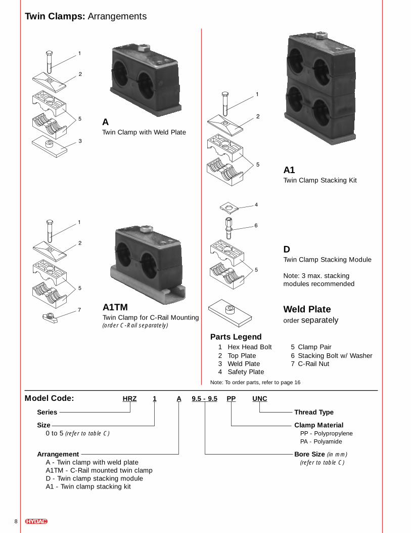
ATwin Clamp with Weld Plate
A1Twin Clamp Stacking Kit
DTwin Clamp Stacking Module
Note: 3 max. stacking modules recommended
A1TMTwin Clamp for C-Rail Mounting(order C-Rail separately)
Twin Clamps: Arrangements
Model Code: HRZ 1 A 9.5 - 9.5 PP UNC
Series Thread Type
Size Clamp Material0 to 5 (refer to table C) PP - Polypropylene
PA - Polyamide
Arrangement Bore Size (in mm)A - Twin clamp with weld plate (refer to table C)A1TM - C-Rail mounted twin clampD - Twin clamp stacking moduleA1 - Twin clamp stacking kit
Parts Legend1 Hex Head Bolt 5 Clamp Pair2 Top Plate 6 Stacking Bolt w/ Washer3 Weld Plate 7 C-Rail Nut4 Safety Plate
Note: To order parts, refer to page 16
Weld Plateorder separately

9
a3
a1
a2
h 2h 3
h 1
.20
(5) 1.18
(30)
ø dø dø dø d
ø .43(ø 11)
.20
(5) .5
1(1
3).4
3(1
0.8)
.94(24)
ø .55(ø 14)
5/16"-18 UNC
.96(24.5)
39 (10)
1/4" -20 UNC
ø .39(ø 10)
.20
(5)
.59
(15)
Plastic Cap
1.10(28)
.43(11)
.43
(11)
.08
(2)
C-Rail C-Rail Nut C-Rail Nut
size 1 sizes 2-5sizes 1-5
Twin Clamps: Dimensions
C-Rail and C-Rail Nut Dimensions
Ød Recommended a1 a2 a3 h1 h2 h3Size Bore Size Nominal Size in in in in in in Bolt Size Weight
in mm Tube O.D. Pipe (mm) (mm) (mm) (mm) (mm) (mm) in lbs (kg)
0.25 6.4 1/4” - .79 1.46 1.42 0.73 1.06 1.69 0.201 0.37 9.5 3/8” - (20) (37) (36) (18.5) (27) (43) 1/4-20 x 1-1/2 (0.09)0.41 10.3 - 1/8”
0.50 12.7 1/2” -2 0.54 13.7 - 1/4” 1.14 2.17 2.09 0.71 1.02 1.71 1/4-20 x 1-1/2 0.30
0.63 16 5/8” - (29) (55) (53) (18) (26) (43.5) (0.14)0.67 17.1 - 3/8”
0.75 19 3/4” -
3 0.84 21.3 - 1/2” 1.42 2.76 2.64 0.93 1.46 2.15 5/16-18 x 1-3/4 0.400.87 22 7/8” - (36) (70) (67) (23.5) (37) (54.5) (0.18)1.00 25.4 1” -
4 1.05 26.7 - 3/4” 1.77 3.35 3.23 1.02 1.65 2.34 5/16-18 x 2 0.44(45) (85) (82) (26) (42) (59.5) (0.20)
1.26 32 1-1/4” -5 1.33 33.7 - 1” 2.20 4.33 4.17 1.26 2.13 2.81 5/16-18 x 2-1/2 0.60
1.50 38 1-1/2” - (56) (110) (106) (32) (54) (71.5) (0.27)1.65 42 - 1-1/4”
Note: Dimensions are shown in inches (millimeters).Table C

10
ASingle Clamp with Weld Plate
A1Single Clamp Stacking Kit
DSingle Clamp Stacking Module
Note: 3 max. stacking modules recommended
A1TMSingle Clamp for C-Rail Mounting(order C-Rail separately)
Standard Duty Clamps With Rubber Inserts: Arrangements
Model Code: HREL 4 A 12-7 PP UNC
Series Thread Type
Size Metal Components Materials4, 6 (refer to table D) omit - Carbon Steel
A4 - Stainless Steel 316
Arrangement Clamp MaterialA - Single clamp with weld plate PP - PolypropyleneA1TM - C-Rail mounted clamp PA - PolyamideD - Single clamp stacking moduleA1 - Single clamp stacking kit Bore Size (in mm)
(refer to table D)
Parts Legend1 Hex Head Bolt 5 Clamp Pair2 Top Plate 6 Rubber Insert3 Weld Plate 7 Stacking Bolt4 Safety Plate 7 C-Rail Nut
Note: To order parts, refer to page 17
Weld Plateorder separately

11
a1
ø d1
s
1.18(30)
ø d
a2
h 1
a3
h 2
s
ød 2
1.10(28)
.43(11)
.43
(11)
ø .39(ø 10)
.20
(5)
.59
(15)
Plastic Cap
.96(24.5)
39 (10)
1/4" -20 UNC
.08
(2)
C-Rail and C-Rail Nut Dimensions
C-Rail C-Rail Nut
Standard Duty Clamps with Rubber Inserts: Dimensions
Note: Dimensions are shown in inches (millimeters).
EE-Rubber Insert RecommendedClamp Bore Size Nominal Size D1 D2 H1 H2 A1 A2 A3 S Bolt Size WeightSize Size ø D Tube
PipeHose O.D. in in in in in in in in (in) lbs (kg)
in mm O.D. Min (in) Max (in) (mm) (mm) (mm) (mm) (mm) (mm) (mm) (mm)
0.24 6 - - 0.22 0.240.32 8 1/16” - 0.30 0.320.39 10 - 1/8” 0.37 0.390.47 12 - - 0.45 0.47
4 2/4 L0.50 12.7 1/2” - 0.48 0.50 1.00 1.22 0.925 1.85 1.57 2.32 2.24 0.118 1/4-20x1 3/4 330.55 14 - - 0.53 0.55 (25.5) (31) (23.5) (47) (40) (59) (57) (3) (0.15)0.59 15 - - 0.57 0.590.63 16 5/8” - 0.61 0.630.68 17.2 - 3/8” 0.66 0.680.75 19 3/4” - 0.73 0.75
0.79 20 - 1/2” 0.77 0.790.87 22 7/8” - 0.85 0.870.98 25 1” - 0.96 0.98
6 3/6 L 1.06 26.9 - 3/4” 1.04 1.06 1.54 1.81 1.40 2.80 2.60 3.46 3.39 0.118 1/4-20x2 3/4 0.681.10 28 - - 1.08 1.10 (39) (46) (35.5) (71) (66) (88) (86) (3) (0.31)1.18 30 - - 1.16 1.181.26 32 1 1/4” - 1.24 1.26
Table D

12
SSingle Clamp with Weld Plate
S1Single Clamp Stacking Kit
ASingle Clamp Stacking Module
Note: 3 max. stacking modules recommended
S1TMSingle Clamp for C-Rail Mounting(order C-Rail separately)
Heavy Duty Clamps With Rubber Inserts: Arrangements
Model Code: HRES 4 S 35 PP UNC
Series Thread Type
Size Clamp Material2 to 7 (refer to table E) PP - Polypropylene
PA - Polyamide
Arrangement Bore Size (in mm)S - Single clamp with weld plate (refer to table E)S1TM - C-Rail mounted clampA - Single clamp stacking moduleS1 - Single clamp stacking kit
Parts Legend1 Hex Head Bolt 5 Clamp Pair2 Top Plate 6 Rubber Insert3 Weld Plate 7 Stacking Bolt4 Safety Plate 7 C-Rail Nut
Note: To order parts, refer to page 18
Weld Plateorder separately

13
.50(12.5)
.20
(5)
3/8" -16 UNC
.87
(22)
1.57(40) ø .98
(ø 25)
ø .71(ø 18)
.24
(6)
.28
(7)
.79
(20)
.45(11.5)
7/16" -14 UNC
ø .98(ø 25)
ø .79(ø 20)
.24
(6)
.33
(8.5
)
.91
(23)
.45
(11.5)
C-Rail
sizes 1-4
C-Rail Nut C-Rail Nut
sizes 1-3 size 4
a1
ø d1
s
b
ø d
a2
h 1
a3
h 2
s
ød 2
C-Rail and C-Rail Nut Dimensions
Standard Duty Clamps with Rubber Inserts: Dimensions
Note: Dimensions are shown in inches (millimeters).
EE-Rubber Insert RecommendedClamp Bore Size Nominal Size D1 D2 B H1 H2 A1 A2 A3 S Bolt Size WeightSize Size ø D Tube
PipeHose O.D. in in in in in in in in in (in) lbs (kg)
in mm O.D. Min (in) Max (in) (mm) (mm) (mm) (mm) (mm) (mm) (mm) (mm) (mm)
0.24 6 - - 0.22 0.240.32 8 1/16” - 0.30 0.320.39 10 - 1/8” 0.37 0.390.47 12 - - 0.45 0.47
2 2/4 L0.50 12.7 1/2” - 0.48 0.50 1.00 1.22 1.18 0.925 1.85 1.57 2.32 2.24 0.118 1/4-20x1 3/4 330.55 14 - - 0.53 0.55 (25.5) (31) (30) (23.5) (47) (40) (59) (57) (3) (0.15)0.59 15 - - 0.57 0.590.63 16 5/8” - 0.61 0.630.68 17.2 - 3/8” 0.66 0.680.75 19 3/4” - 0.73 0.75
0.79 20 - 1/2” 0.77 0.790.87 22 7/8” - 0.85 0.870.98 25 1” - 0.96 0.98
3 3/6 L 1.06 26.9 - 3/4” 1.04 1.06 1.54 1.81 1.18 1.40 2.80 2.60 3.46 3.39 0.118 1/4-20x2 3/4 0.681.10 28 - - 1.08 1.10 (39) (46) (30) (35.5) (71) (66) (88) (86) (3) (0.31)1.18 30 - - 1.16 1.181.26 32 1 1/4” - 1.24 1.26
1.33 33.7 - 1” 1.31 1.331.38 35 - - 1.36 1.381.50 38 1 1/2” - 1.48 1.501.58 40 - - 1.56 1.58
4 41.65 42 - - 1.63 1.65 2.56 2.91 1.77 2.11 4.21 3.56 5.51 4.53 0.39 1/2-13x4 3.171.79 45.5 - - 1.77 1.79 (65) (74) (45) (53.5) (107) (90.5) (140) (115) (10) (1.44)1.89 48 - 1 1/2” 1.87 1.892.01 51 2” - 1.99 2.012.10 53.4 - - 2.08 2.102.22 56.4 - - 2.20 2.22
2.36 60 - 2” 2.34 2.362.56 65 - - 2.54 2.56
3.50 3.86 2.36 2.70 5.39 4.80 7.09 5.98 0.39 5/8-11x5 1/2 5.915 5 2.76 70 - - 2.74 2.76(89) (98) (60) (68.5) (137) (122) (180) (152) (10) (6.73)2.87 73 - 2 1/2” 2.85 2.87
2.99 76 3” - 2.97 2.99
3.27 83 - - 3.19 3.27
6 63.50 89 3 1/2” 3” 3.43 3.50 4.57 5.20 3.15 3.88 7.76 6.61 8.86 8.07 0.59 3/4-10x7 1/2 14.843.70 94 - - 3.62 3.70 (116) (132) (80) (98.5) (197) (168) (225) (205) (15) (6.73)3.98 101 4” 3 1/2” 3.90 3.98
4.26 108 - - 4.17 4.266.06 6.61 3.54 4.47 8.94 8.07 10.63 9.92 0.59 7/8-9x8 1/2 22.937 7 4.49 114 - 4” 4.41 4.49(154) (168) (90) (113.5) (227) (205) (270) (252) (15) (10.4)5.24 133 - - 5.16 5.24
Table E

Hex Head Boltsize model code
0 SCREW H 1/4 - 20 x 1.25 GR20 (B arrange) SCREW H 1/4 - 20 x 1.00 GR2
1 SCREW H 1/4 - 20 x 1.25 GR21(B arrange) SCREW H 1/4 - 20 x 1.00 GR2
2 SCREW H 1/4 - 20 x 1.50 GR22 (B arrange) SCREW H 1/4 - 20 x 1.25 GR2
3 SCREW H 1/4 - 20 x 1.50 GR24 SCREW H 1/4 - 20 x 1.75 GR25 SCREW H 1/4 - 20 x 2.50 GR26 SCREW H 1/4 - 20 x 2.75 GR2
6 (B arrange) SCREW H 1/4 - 20 x 2.50 GR2
DP = Top Platesize model code
0 HRL 0 DP ST ZN1 HRL 1 DP ST ZN2 HRL 2 DP ST ZN3 HRL 3 DP ST ZN4 HRL 4 DP ST ZN5 HRL 5 DP ST ZN6 HRL 6 DP ST ZN7 HRL 7 DP ST ZN
14
Standard Duty Clamps: Parts
AP = Weld Platesize model code
0 HRL 0 AP ST UNC BL1 HRL 1 AP ST UNC BL2 HRL 2 AP ST UNC BL3 HRL 3 AP ST UNC BL4 HRL 4 AP ST UNC BL5 HRL 5 AP ST UNC BL6 HRL 6 AP ST UNC BL7 HRL 7 AP A4 UNC BL
TM = C-Rail Nutsize model code
0 HRL 0-6 TM1/4 ST UNC BL1 HRL 0-6 TM1/4 ST UNC BL2 HRL 0-6 TM1/4 ST UNC BL3 HRL 0-6 TM1/4 ST UNC BL4 HRL 0-6 TM1/4 ST UNC BL5 HRL 0-6 TM1/4 ST UNC BL6 HRL 0-6 TM1/4 ST UNC BL
AF = Stacking Boltsize model code
1 HRL 1 AF ST UNC2 HRL 2 AF ST UNC3 HRL 3 AF ST UNC4 HRL 4 AF ST UNC5 HRL 5 AF ST UNC6 HRL 6 AF ST UNC
EF = Insertsize model code
1 HRL EH PP2 HRL EH PP3 HRL EH PP4 HRL EH PP5 HRL EH PP6 HRL EH PP
HRL = Sefety Platesize model code
1 HRL 0-6 SIP ST ZN2 HRL 0-6 SIP ST ZN3 HRL 0-6 SIP ST ZN4 HRL 0-6 SIP ST ZN5 HRL 0-6 SIP ST ZN6 HRL 0-6 SIP ST ZN
TS = C-Railsize model code39” HRL TS 28x11 ST BL 1M78” HRL TS 28x11 ST BL 2M
1
2
3
6
7
5
8
4
Model Code: HRL 1 KP 10 PPSeriesSize
0 to 6 (refer to table A, page 5)
Clamp PairBore Size (in mm)
(refer to table A, page 5)
Clamp MaterialPP - PolypropylenePA - PolyamideAL - Aluminum
KP = Clamp Pair
Contact Factory for Stainless Steel Component Model Codes

Hex Head Boltsize model code
1 SCREW H 3/8 - 16 x 1.75 GR52 SCREW H 3/8 - 16 x 2.25 GR53 SCREW H 3/8 - 16 x 2.75 GR54 SCREW H 7/16 - 14 x 4.00 GR55 SCREW H 5/8 - 11 x 5.50 GR56 SCREW H 3/4 - 10 x 7.50 GR57 SCREW H 7/8 - 9 x 8.50 GR58 HRS 8 ASKT M30
15
5
Model Code: HRS 1 KP 12.7 PPSeriesSize
1 to 8 (refer to table B, page 6)
Clamp PairBore Size (in mm)
(refer to table B, page 6)
Clamp MaterialPP - PolypropylenePA - PolyamideAL - Aluminum
KP = Clamp Pair
Heavy Duty Clamps: Parts
DP = Top Platesize model code
1 HRS 1 DP ST ZN2 HRS 2 DP ST ZN3 HRS 3 DP ST ZN4 HRS 4 DP ST ZN5 HRS 5 DP ST BL6 HRS 6 DP ST BL7 HRS 7 DP ST BL8 HRS 8 DP ST BL
AP = Weld Platesize model code
1 HRS 1 AP ST UNC BL2 HRS 2 AP ST UNC BL3 HRS 3 AP ST UNC BL4 HRS 4 AP ST UNC BL5 HRS 5 AP ST UNC BL6 HRS 6 AP ST UNC BL7 HRS 7 AP ST UNC BL8 HRS 8 AP ST UNC BL
TM = C-Rail Nutsize model code
2 HRS 1-3 TM3/8 ST UNC BL3 HRS 1-3 TM3/8 ST UNC BL4 HRS 4 TM7/16 ST UNC BL
DAP = Double Weld Platesize model code
1 HRS 1 DAP ST UNC BL2 HRS 2 DAP ST UNC BL3 HRS 3 DAP ST UNC BL4 HRS 4 DAP ST UNC BL5 HRS 5 DAP ST UNC BL6 HRS 6 DAP ST UNC BL7 HRS 7 DAP ST UNC BL
DDP = Double Top Platesize model code
1 HRS 1 DDP ST UNC BL2 HRS 2 DDP ST UNC BL3 HRS 3 DDP ST UNC BL4 HRS 4 DDP ST UNC BL5 HRS 5 DDP ST UNC BL6 HRS 6 DDP ST UNC BL7 HRS 7 DDP ST UNC BL
AF = Stacking Bolt w/ Washersize model code
1 HRS 1 AF ST UNC2 HRS 2 AF ST UNC3 HRS 3 AF ST UNC4 HRS 4 AF ST UNC5 HRS 5 AF ST UNC
SIP = Safety Platesize model code
1 HRS 1 SIP ST ZN2 HRS 2 SIP ST ZN3 HRS 3 SIP ST ZN4 HRS 4 SIP ST ZN5 HRS 5 SIP ST ZN
TS = C-Railsize model code39” HRS TS 40x22 ST BL 1M78” HRS TS 40x22 ST BL 2M
1
2
3
6
7
9
8
4
Contact Factory for Stainless Steel Component Model Codes

16
Twin Clamps: Parts
Hex Head Boltsize model code
1 SCREW H 1/4 - 20 x 1.5 GR22 SCREW H 5/16 - 18 x 1.25 GR23 SCREW H 5/16 - 18 x 1.75 GR24 SCREW H 5/16 - 18 x 2.00 GR25 SCREW H 5/16 - 18 x 2.50 GR2
DP = Top Platesize model code
1 HRZ 1 DP ST ZN2 HRZ 2 DP ST ZN3 HRZ 3 DP ST ZN4 HRZ 4 DP ST ZN5 HRZ 5 DP ST BL
AP = Weld Platesize model code
1 HRZ 1 AP ST UNC BL2 HRZ 2 AP ST UNC BL3 HRZ 3 AP ST UNC BL4 HRZ 4 AP ST UNC BL5 HRZ 5 AP ST UNC BL
TM = C-Rail Nutsize model code
1 HRZ 2/5 TM5/16 ST UNC UNC KAP2 HRZ 2/5 TM5/16 ST UNC UNC O-Ring3 HRZ 2/5 TM5/16 ST UNC UNC O-Ring4 HRZ 2/5 TM5/16 ST UNC UNC O-Ring5 HRZ 2/5 TM5/16 ST UNC UNC O-Ring
AF = Stacking Bolt w/ Washersize model code
1 HRZ 1 AF ST UNC2 HRZ 2 AF ST UNC3 HRZ 3 AF ST UNC4 HRZ 2 AF ST UNC5 HRZ 2 AF ST UNC
SIP = Safety Platesize model code
1 HRZ 1 SIP ST ZN2 HRZ 2/5 SIP ST ZN3 HRZ 2/5 SIP ST ZN4 HRZ 2/5 SIP ST ZN5 HRZ 2/5 SIP ST ZN
TS = C-Railsize model code39” HRS TS 28x11 ST BL 1M78” HRS TS 28x11 ST BL 2M
1
2
3
6
7
4
5
Model Code: HRS 1 KP 9.5-9.5 PPSeriesSize
0 to 5 (refer to table C, page 9)
Clamp PairBore Size (in mm)
(refer to table C, page 9)
Clamp MaterialPP - PolypropylenePA - Polyamide
KP = Clamp Pair
Contact Factory for Stainless Steel Component Model Codes

17
5 6
Model Code: HRL 4 KP PPSeriesSize
4, 6 (refer to table D, page 11)
Clamp PairClamp Material
PP - PolypropylenePA - Polyamide
Model Code: HRES 2/4 L EE 12SeriesSize
2/4 L, 3/6 L (refer to table D, page 11)
Rubber InsertBore Size (in mm)
(refer to table D, page 11)
KP = Clamp Pair EE = Rubber Insert
Hex Head Boltsize model code
4 SCREW H 1/4 - 20 x 1.75 GR26 SCREW H 1/4 - 20 x 2.75 GR2
DP = Top Platesize model code
4 HRL 4 DP ST ZN6 HRL 6 DP ST ZN
Standard Duty Clamps with Rubber Inserts: Parts
AP = Weld Platesize model code
4 HRL 4 AP ST UNC BL6 HRL 6 AP ST UNC BL
TM = C-Rail Nutsize model code
4 HRL 0-6 TM1/4 ST UNC BL6 HRL 0-6 TM1/4 ST UNC BL
AF = Stacking Boltsize model code
4 HRL 4 AF ST UNC6 HRL 6 AF ST UNC
HRL = Safety Platesize model code
1 HRL 0-6 SIP ST ZN2 HRL 0-6 SIP ST ZN3 HRL 0-6 SIP ST ZN4 HRL 0-6 SIP ST ZN5 HRL 0-6 SIP ST ZN6 HRL 0-6 SIP ST ZN
TS = C-Railsize model code39” HRL TS 28x11 ST BL 1M78” HRL TS 28x11 ST BL 2M
1
2
3
7
8
4
Contact Factory for Stainless Steel Component Model Codes

18
Heavy Duty Clamps with Rubber Inserts: Parts
Hex Head Boltsize model code
1 SCREW H 3/8 - 16 x 1.7 GR52 SCREW H 3/8 - 16 x 2.25 GR53 SCREW H 3/8 - 16 x 2.75 GR54 SCREW H 7/16 - 14 x 4.00 GR55 SCREW H 5/8 - 11 x 5.50 GR56 SCREW H 3/4 - 10 x 7.50 GR57 SCREW H 7/8 - 9 x 8.50 GR5
DP = Top Platesize model code
2 HRS 2 DP ST ZN3 HRS 3 DP ST ZN4 HRS 4 DP ST ZN5 HRS 5 DP ST BL6 HRS 6 DP ST BL7 HRS 7 DP ST BL
AP = Weld Platesize model code
2 HRS 2 AP ST UNC BL3 HRS 3 AP ST UNC BL4 HRS 4 AP ST UNC BL5 HRS 5 AP ST UNC BL6 HRS 6 AP ST UNC BL7 HRS 7 AP ST UNC BL
TM = C-Rail Nutsize model code
2 HRS 1-3 TM3/8 ST UNC BL3 HRS 1-3 TM3/8 ST UNC BL4 HRS 4 TM7/16 ST UNC BL
AF = Stacking Bolt w/ Washersize model code
2 HRS 2 AF ST UNC3 HRS 3 AF ST UNC
SIP = Safety Platesize model code
2 HRS 2 SIP ST ZN3 HRS 3 SIP ST ZN
TS = C-Railsize model code39” HRS TS 40x22 ST ML 1M78” HRS TS 40x22 ST ML 2M
1
2
3
7
5 6
8
4
Model Code: HRES 4 KP PPSeriesSize
2 to 7 (refer to table E, page 13)
Clamp PairClamp Material
PP - PolypropylenePA - Polyamide
Model Code: HRES 4 EE 33.7SeriesSize
2/4 L to 7 (refer to table E, page 13)
Rubber InsertBore Size (in mm)
KP = Clamp Pair EE = Rubber Insert
Contact Factory for Stainless Steel Component Model Codes

19
Technical Specifications:
Properties of Materials (clamp pairs)
Recommended Distance Between Clamps
Pipe Size Distance Tube Size Distance1/4” 4’ 1/16” 3’
1/2” 4’ 1/8” 3’
3/4” 5’ 1/4” 3’
1” 5’ 3/8” 3’
1 1/4” 7’ 1/2” 3’
1 1/2” 8’ 5/8” 4’
2” 10’ 3/4” 4’
2 1/2” 10’ 7/8” 4’
3” 12’ 1” 5’
4” 13’ 1 1/4” 7’
5” 13’ 1 3/4” 7’
6” 14’ 1 3/4” 7’
2’ 7’
Resistant to mostaqueous solutionsof inorganic salts,minerals, andorganic acids,even at hightemperatures.
Resistant to organicsolvents, diluteacids, and bases.Resistant toradiation.
Resistant toneutral and seawater, organicacids, esters, oils,and inorganic salt solutions.
Polypropylene PP Polyamide PA Aluminum AL
Mechanical PropertiesTensile Strength 4200 psi 7800-11500 psi –
Flexural Yield Strength 7600 psi 20500 psi –
Impact Strength No Failure No Failure –(Izod Method)
Tensile Test – – 2800 psi
Brinell Hardness Number – – 60 BHN
Modules of Elasticity – – 9.7 x 10811.1 x 106 psi
Thermal PropertiesContinuous Service -22° to 194°F -40° to 284°F -67° to 500°FTemperature Range -30° to 90°C -40° to 140°C -55° to 260°C
Electrical PropertiesVolume Resistivity 1018 Ohm-cm 1015 Ohm-cm –
Chemical PropertiesChemical Resistance

©C
opyr
ight
200
0 H
YD
AC
TE
CH
NO
LO
GY
CO
RP
OR
AT
ION
- B
roch
ure
- H
ose,
Tub
e, a
nd P
ipe
Cla
mps
#0
2068
188
/ 05
.00
HYDAC TECHNOLOGY CORPORATION2260 City Line Road • Bethlehem, PA 18017Phone (610) 266-0100 • Fax (610) 264-3540www.hydacusa.com • [email protected]
High Pressure Ball ValvesHYDAC offers a complete line of high pressure ball valves. These valvesfeature full unrestricted flow, positive shut-off, and have pressure ratings of upto 7,250 psi. Available sizes range from 1/4” thru 2” with NPT, SAE, or SAEsplit flange connections. Options include locking devices, pneumatic orelectrical actuators, limit switches, and offset or straight handles. For completeinformation on HYDAC High Pressure Ball Valves, contact HYDAC at610-266-0100 and request a catalog.
Other Products from HYDAC’s Clamps, Valves, and Accessories Line
TestPoints Series 1620HYDAC offers a complete line of TestPoints Series 1620. TestPoints arecompact, self sealing couplings that provide access to hydraulic and pneumaticsystems for pressure measurements to 9000 psi. Mating adaptors or hoseconnections can be connected without loss of fluid while the system is operating.They are available in 1620 (M16x2.0) connection threads with variety of screw-inport configurations. For complete information on HYDAC TestPoints Series 1620,contact HYDAC at 610-266-0100 and request a catalog.
Flow, Needle, and Check ValvesWhen it comes to flow control valves, HYDAC once again provides a completeline of high quality solutions. Flow, Needle, and check valves are designed tobe safe, precise, and easy to use. The valves are constructed of high qualitymaterials to be compatible with the type of fluid being used. These valvescome with pressure ratings of up to 5,000 psi. Both inline and manifold designsare available. HYDAC would be glad to help you determine which flow controlvalve(s) would be appropriate for your application. For more information on theseproducts, or help selecting the right valve, contact HYDAC at 610-266-0100.
Multi Station Gauge IsolatorsHYDAC Multi-Station Gauge Isolators allow for multiple pressure readings tobe taken by a single gauge. They are offered with or without a built-in gauge.Available in 6 to 9 stations, these gauge isolators have operating pressureranges of 4500 psi at measuring points. For help in selecting the proper gaugeisolator for your application call HYDAC at 610-266-0100.
Request catalog # 02068169
Request catalog #02070729
Request catalog # 02068165
Request catalog # 02068186
![CHAPTER 71 - Robinson R44 · shown. To replace, order C727-2 tube, A729-31 tube, LW-18575** Nipple and [2] MS21919WDG12 clamps.) 16](https://static.fdocuments.us/doc/165x107/5f160c76b06b0b732b03d68d/chapter-71-robinson-r44-shown-to-replace-order-c727-2-tube-a729-31-tube-lw-18575.jpg)