HORIZONTAL TIMBER DIAPHRAGMS FOR WIND AND EARTHQUAKE ...2)0135.pdf · HORIZONTAL TIMBER DIAPHRAGMS...
8
135 HORIZONTAL TIMBER DIAPHRAGMS FOR WIND AND EARTHQUAKE RESISTANCE P. C. Smith, 1 D. J. Dowrick2 and J. A. Dean3 ABSTRACT This paper discusses the principles of horizontal timber diaphragm behaviour under in-plane loading, gives guidance on analysis, design and details, and reviews relevant research. Plywood, particle board and solid timber boarding are all relevant sheathing materials for wind and earthquake resistance, provided that appropriate stiffness is provided and the design provisions ensure that brittle failure modes are suppressed. 1. INTRODUCTION This paper is one of a series of papers on the design of timber structures for wind and earthquake resistance, resulting from the work of a joint committee of the New Zealand Timber Society and the New Zealand National Society for Earthquake Engineering (Williams, 1986). This paper discusses the behaviour and design of horizontal timber diaphragms which will perform well in both wind and earthquake loading. There are two alternative contrasting design approaches that may be adopted for diaphragms, both of which relate to the high degree of non-linearity which readily occurs in diaphragms under earthquake loads as discussed below. (1) Suppression of Non-linearity The distribution of loading through the diaphragm to the vertical structure and the control of deflections can be much more easily and reliably predicted if significant non-linearity in the nail deformations is suppressed. In the majority of buildings this will be the preferable and economical procedure. The seismic force factors for parts and portions of buildings in the New Zealand loadings code {NZS 4203) should be used, and the design of diaphragm nailing for the lateral loads derived using the appropriate seismic force factors will generally ensure that the response of the diaphragm is predictable. Potential brittle failure of the chords of diaphragms and around openings in the diaphragm must still be prevented. "Spencer, Holmes-Miller Partners Ltd, ( Welling ton 'Physics and Engineering Laboratory, .DSIR, Lower Hutt University of Canterbury (2) Ductile Inelastic Diaphragms In this approach the inelastic (non-linear) behaviour of the diaphragm at design loads is allowed for explicitly in calculating the loads, load distribution and deflections. The energy absorption and ductility of the diaphragm implied by the elasticity may be utilised to reduce the loadings generated within the diaphragm (by the use of appropriate code SM factors), thus resulting in reduced design forces that are transferred to the supporting vertical structure. As with timber sheathed walls {Dowrick and Smith, 1986), the achievement of a ductile failure mode is essential. This is achieved by providing adequate extra strength for all other failure modes to ensure that failure occurs through nail deformation. Premature failure of the chords, in framing around openings, in shear panels, or in the diaphragm connections to vertical structure must be prevented by capacity design procedures= Control of deformations that will occur in the inelastic structure must ensure that inter-storey drifts at any location along the diaphragm are not excessive. 2. RESEARCH INTO DIAPHRAGM BEHAVIOUR A great deal of research has been done into various aspects of timber diaphragms involving a variety of materials and sheathing patterns. Brief descriptions of a selection of research reports have conveniently been published in two publications by the Applied Technology Council (1980, 1981). In this present paper we will restrict our attention to a few papers particularly pertinent to the subject of this paper. The first tests on timber diaphragms were carried out by Green BULLETIN OF THE NEW ZEALAND NATIONAL SOCIETY FOR EARTHQUAKE ENGINEERING, Vol. 19, No. 2, June 1986
-
Upload
truongthuy -
Category
Documents
-
view
229 -
download
4
Transcript of HORIZONTAL TIMBER DIAPHRAGMS FOR WIND AND EARTHQUAKE ...2)0135.pdf · HORIZONTAL TIMBER DIAPHRAGMS...

135
HORIZONTAL TIMBER DIAPHRAGMS FOR WIND AND EARTHQUAKE RESISTANCE
P. C. Smith, 1 D. J . Dowrick2 and J. A. Dean3
ABSTRACT
This paper discusses the principles of horizontal timber diaphragm behaviour under in-plane loading, gives guidance on analysis, design and details, and reviews relevant research. Plywood, particle board and solid timber boarding are all relevant sheathing materials for wind and earthquake resistance, provided that appropriate stiffness is provided and the design provisions ensure that brittle failure modes are suppressed.
1. INTRODUCTION This paper is one of a series of
papers on the design of timber structures for wind and earthquake resistance, resulting from the work of a joint committee of the New Zealand Timber Society and the New Zealand National Society for Earthquake Engineering (Williams, 1986). This paper discusses the behaviour and design of horizontal timber diaphragms which will perform well in both wind and earthquake loading. There are two alternative contrasting design approaches that may be adopted for diaphragms, both of which relate to the high degree of non-linearity which readily occurs in diaphragms under earthquake loads as discussed below.
(1) Suppression of Non-linearity
The distribution of loading through the diaphragm to the vertical structure and the control of deflections can be much more easily and reliably predicted if significant non-linearity in the nail deformations is suppressed. In the majority of buildings this will be the preferable and economical procedure.
The seismic force factors for parts and portions of buildings in the New Zealand loadings code {NZS 4203) should be used, and the design of diaphragm nailing for the lateral loads derived using the appropriate seismic force factors will generally ensure that the response of the diaphragm is predictable. Potential brittle failure of the chords of diaphragms and around openings in the diaphragm must still be prevented.
"Spencer, Holmes-Miller Partners Ltd, (Welling ton 'Physics and Engineering Laboratory, .DSIR, Lower Hutt University of Canterbury
(2) Ductile Inelastic Diaphragms
In this approach the inelastic (non-linear) behaviour of the diaphragm at design loads is allowed for explicitly in calculating the loads, load distribution and deflections. The energy absorption and ductility of the diaphragm implied by the elasticity may be utilised to reduce the loadings generated within the diaphragm (by the use of appropriate code SM factors), thus resulting in reduced design forces that are transferred to the supporting vertical structure.
As with timber sheathed walls {Dowrick and Smith, 1986), the achievement of a ductile failure mode is essential. This is achieved by providing adequate extra strength for all other failure modes to ensure that failure occurs through nail deformation.
Premature failure of the chords, in framing around openings, in shear panels, or in the diaphragm connections to vertical structure must be prevented by capacity design procedures= Control of deformations that will occur in the inelastic structure must ensure that inter-storey drifts at any location along the diaphragm are not excessive.
2. RESEARCH INTO DIAPHRAGM BEHAVIOUR
A great deal of research has been done into various aspects of timber diaphragms involving a variety of materials and sheathing patterns. Brief descriptions of a selection of research reports have conveniently been published in two publications by the Applied Technology Council (1980, 1981). In this present paper we will restrict our attention to a few papers particularly pertinent to the subject of this paper.
The first tests on timber diaphragms were carried out by Green
BULLETIN OF THE NEW ZEALAND NATIONAL SOCIETY FOR EARTHQUAKE ENGINEERING, Vol. 19, No. 2, June 1986
136
et al. (1934), on 24 x 40 ft diaphragms with three different solid boarding patterns, subjected to monotonic loading. The problem of flexibility was recognised and deflection criteria were proposed for limiting masonry wall deflection. Attention was first paid to plywood sheathed diaphragms in the 1950's, starting with monotonic load tests by Countryman (1952) and specimens with L/B ratios of 2,0 and 3.33, from which deflection formulae were developed (the form of which is still used). Waiford (1978) found an error in Countryman's derivation of nail slip deflection, and James and Bryant (1984) have shown that the New Zealand code formulae (in NZS 3603 and NZS 3615) underestimate the strength and overestimate the deflections of plywood diaphragms and shear walls. They also noted that the nail-slip component of deflection is a significant part of the total deflection, and is affected by construction factors such as panel layout.
Openings in diaphragms obviously impose complications in behaviour predictions. Tissel (1966) carried out a series of tests on a number of plywood sheathed 16 x 48 ft diaphragms, two of which contained openings 8 ft square and 4 ft square respectively. Higher stresses were measured in the sheathing and framing around the openings, and the need for extra framing members was noted. Dean et al. (1984) have outlined techniques by which panel shears and framing forces may be determined in the presence of openings, introducing a simple procedure called the "Shear Transfer Method", which was verified by more rigorous finite element analyses.
Most tests have been on simply supported diaphragms, so Tarpy et al. (1984) examined continuous plywood clad diaphragms 8 x 16 ft in size with varying panel layouts and load positions. Their results tended to confirm current practice, but the test specimens were perhaps too small in relation to panel size to give a complete picture.
Computer programs for the analysis of buildings usually assume that floor diaphragms are rigid. While this assumption is reasonably true for concrete construction, it is far from the case for timber diaphragms. Recently two dynamic analysis programs incorporating flexible floor diaphragms have been developed by Button et al. (1984) and Jain and Jennings (1984) . both these papers confirm that diaphragm flexibility modifies the response characteristics of structures, in some cases increasing the forces compared with those obtained assuming rigid diaphragms.
3. DESIGN OF DIAPHRAGMS
3.1 Analysis
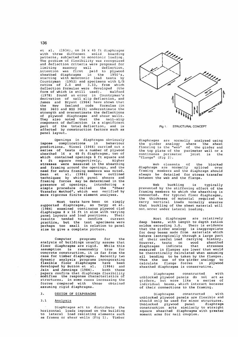
Diaphragms act to distribute the horizontal loads imposed on the building to lateral load resisting elements such as frames or shear walls (Fig 1). Timber
Fig 1. STRUCTURAL CONCEPT
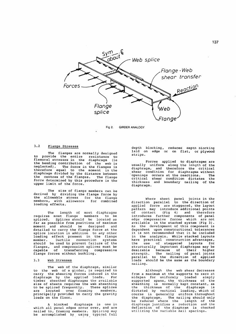
diaphragms are normally analysed using the girder analogy where the sheet flooring is the "web" of the girder and the top plate of the perimeter wall or a continuous perimeter joist is the "flange" (Fig 2).
Web elements of the blocked diaphragm are normally spliced over framing members and the diaphragm should always be detailed for stress transfer between the web and the flange.
Web buckling is typically prevented by the stiffening effect of the framing members to which the sheathing is connected. For typical floor diaphragms, the thickness of material required to carry vertical loads normally ensures that buckling of the sheet material will notvoccur under lateral loading.
Most diaphragms are relatively deep beams, with length to depth ratios seldom exceeding 3.0. There is evidence that the girder analogy is inappropriate for deep beams made from materials which behave isotropically through a large part of their useful load carrying history. However, tests on wood sheathed diaphragms indicate that stresses measured in flanges are lower than would be theoretically calculated when assuming all bending to be taken by the flanges. Thus the use of the girder analogy to calculate flange forces in plywood sheathed diaphragms is conservative.
Diaphragms constructed with unblocked plywood panels do not act as gi rders, but more like a series of individual beams, which interact because of their connections to the framing.
Diaphragms constructed with unblocked plywood panels are flexible and should only be used for minor structures. Unblocked plywood panel diaphragm construction acts similarly to straight square sheathed diaphragms with greater moment arms for nail couples.
137
Fig 2. GIRDER ANALOGY
3.2 Flange Stresses The flanges are normally designed
to provide the entire resistance to flexural stresses in the diaphragm (ie the bending contribution of the web is neglected). The force in the flanges is therefore equal to the moment in the diaphragm divided by the distance between the centres of the flanges. The flange force determined by this procedure is the upper limit of the force.
The size of flange members can be derived by dividing the flange force by the allowable stress for the flange members, with allowance for combined loading effects.
The length of most diaphragms requires most flange members to be spliced. Splices should be located as far as possible from positions of maximum moment and should be designed and detailed to carry the flange force at the splice location in addition to any other loading effect present in the flange member. Ductile connection systems should be used to prevent failure of the flanges, and compression splices must be capable of transferring compressive flange forces without buckling.
3.3 Web Stresses
The web of the diaphragm, similar to the web of a girder, is required to carry the shearing forces induced in the diaphragm by the applied loads. For timber sheathed diaphragms the available size of sheets requires the web sheathing to be spliced frequently. These splices are located over framing members, principally provided to carry the gravity loads on the floor.
A blocked diaphragm is one in which all panel edges occur over, and are nailed to, framing members. Splicing may be accomplished by using typical full
depth blocking, reduced depth blocking laid on edge or on flat, or plywood strips.
Forces applied to diaphragms are usually uniform along the length of the diaphragm, and therefore the critical shear condition for diaphragms without openings occurs at the reactions. The critical shear condition dictates the thickness and boundary nailing of the diaphragm.
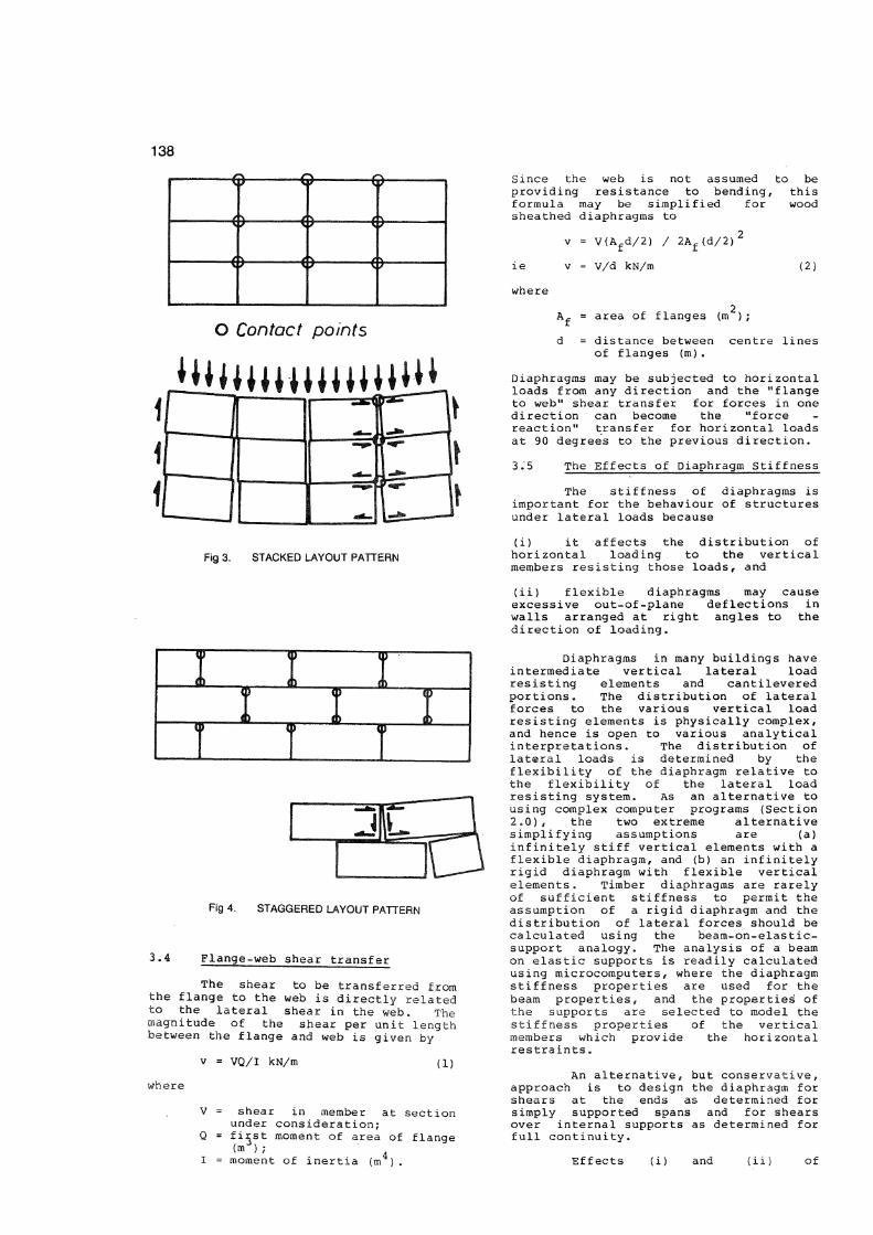
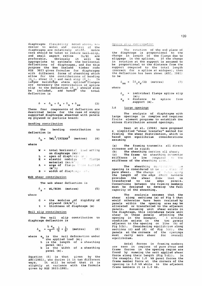
Where sheet panel joints in the direction parallel to the direction of applied force are staggered, the layout pattern may introduce additional points of contact (Fig 4) and therefore introduces further components of panel edge compressive forces which are not available in the stacked system (Fig 3). As the development of this component is dependent upon constructional tolerances it is not recommended that it be included in the analysis. While stacked layouts have practical construction advantages, the use of staggered layouts for structurally important diaphragms may be desirable because of their higher strength. The nailing of panel joints parallel to the direction of applied loads should be the same as the boundary nailing.
Although the web shear decreases from a maximum at the supports to zero at midspan for uniformly loaded simply supported spans, the thickness of the sheathing is normally kept constant, as the thickness of the diaphragm is dictated by vertical loading, which of course is generally uniform throughout the diaphragm. The nai1ing should only be reduced where the length of the diaphragm justifies a reduction and the deflection of the diaphram is checked utilizing the variable nail spacings.
138
O Contact points
i i i tmnit i tutt t t I LI
Fig 3. STACKED LAYOUT PATTERN
Since the web is not assumed to be providing resistance to bending, this formula may be simplified for wood sheathed diaphragms to
v = V(A fd/2) / 2A f(d/2)'
v = V/d kN/m (2)
where
area of flanges (m );
d = distance between centre lines of flanges (m).
Diaphragms may be subjected to horizontal loads from any direction and the "flange to web" shear transfer for forces in one direction can become the "force reaction" transfer for horizontal loads at 90 degrees to the previous direction.
3.5 The Effects of Diaphragm Stiffness
The stiffness of diaphragms is important for the behaviour of structures under lateral loads because
(i) it affects the distribution of hori zontal loading to the vertical members resisting those loads, and
t > <
> c > t
) •
o < ) 0 > o
> < > ( s
5S Fig 4. STAGGERED LAYOUT PATTERN
3.4 Flange-web shear transfer
The shear to be transferred from the flange to the web is directly related to the lateral shear in the web. The magnitude of the shear per unit length between the flange and web is given by
v = VQ/I kN/m (l) where
V = shear in member at section under consideration;
Q = first moment of area of flange (m ) ;
I = moment of inertia (m ).
(ii) flexible diaphragms may cause excessive out-of-plane deflections in walls arranged at right angles to the direction of loading .
Diaphragms in many buildings have intermediate vertical lateral load resisting elements and cantilevered portions. The distribution of lateral forces to the various vertical load resisting elements is physically complex, and hence is open to various analytical interpretations. The distribution of lateral loads is determined by the flexibility of the diaphragm relative to the flexibility of the lateral load resisting system. As an alternative to using complex computer programs (Section 2.0), the two extreme alternative simplifying assumptions are (a) infinitely stiff vertical elements with a flexible diaphragm, and (b) an infinitely rigid diaphragm with flexible vertical elements. Timber diaphragms are rarely of sufficient stiffness to permit the assumption of a rigid diaphragm and the distribution of lateral forces should be calculated using the beam-on-elastic-support analogy. The analysis of a beam on elastic supports is readily calculated using microcomputers, where the diaphragm stiffness properties are used for the beam properties, and the properties' of the supports are selected to model the stiffness properties of the vertical members which provide the horizontal restraints.
An alternative , but conservative, approach is to design the diaphragm for shears at the ends as determined for simply supported spans and for shears over internal supports as determined for full continuity.
Effects (i) and (ii) of
139
diaphragms flexibility noted above, are easier to model and control if the diaphragms are relatively stiff. Hence care should be taken to reduce nail-slip, and small aspect ratios (L/B) are preferable. Obviously it will be appropriate to estimate the horizontal deflections of diaphragms, and for this purpose the New Zealand timber code N2S 3603 gives formulae for diaphragms with different forms of sheathing which allow for the contributions of bending (A b) , shear (A ) and nail slip (A ). in larger buildings where spliced nflanges are necessary the contributicn of splice slip to the deflection (A ) should also be included, and henci s the total deflection is
A = A, + A + A + A b s n ss
(3)
These four components of deflection are described below for the case of simply supported diaphragms sheathed with panels eg plywood or particle board:
Bending contribution
The bending contribution to deflection is
A f a = 5WL 3/192EAB 2 (metres) (4)
where
W = total horizontal load acting on diaphragm (kN)?
L = span of diaphr * ; E = elastic modal ;; ~ 5
material (kn/m' : A = area of f lar v- - \ on
(m ); B = width of dia^r.^
Web shear contribution
The web shear deflection is A g = WL/8GBt (metres) (5)
where G = the modulus rigidity of
plywood (kN/m ) ; t = thickness of diaphragm (m)
Nail slip contribution
The nail slip contribution to diaphragm deflection is
L e A n = *"T~^ (rT + F> Metres) (6)
where e is the nail deformation under the applied load (m);
h is the length of a sheathing panel (m);
b is the width of a sheathing panel (m).
Equation (6) is that given by the ATC (1981), who derive it in two different ways. It will be noted that it is slightly at variance with the formula given by NZS 3603:1981.
Splice slip contribution
The rotation of the end plane of the diaphragm is proportional to the change in length of the flange due to slippage in the splices. If the change in rotation at the support is assumed to be proportional to the distance from the support compared to the total length (correct for a splice at midspan), then the deflection has been shown (ATC, 1981) to be
IA x /2B c s (metres) (7)
where
3.6
= individual flange splice slip : (m); , = distance to splice from
.support (m) . Large openings
The analysis of diaphragms with large openings is complex and requires finite element programs to establish the stress distribution around openings.
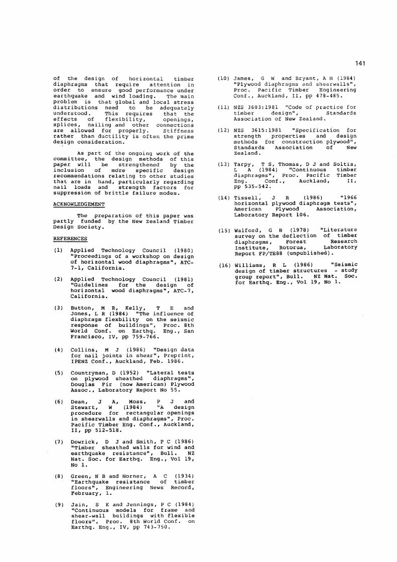
Dean et al. (1984) have proposed a simplified "shear transfer" method for finding the shear distribution, which is based upon equilibrium considerations assuming
(a) The framing transmits all direct stresses and is rigid; (b) The sheathing carries all shear; (c) The frame to sheathing connector stiffness is low compared the stiffness of the sheathing
The sheathing su . -: ...-e opening is considered to _ t •.a ; t pure shear . The change :c "> :.c*q the length of the edge chorri r^mbers provides the shear flow that is transferred to the edge panels. Connections between the framing members must be designed to develop the full capacity of the sheathing.
The analysis assumes that the shear along sections (a) of Fig 5 that would otherwise have been resisted by panels within the opening area may be allocated or transferred to the adjacent panels. Assuming unit shear exists in the diaphragm, this introduces twice unit shear in these panels adjoining the opening in the example. A similar condition exists in the two panels adjacent to the opening on line (b) of Fig 5(b). Considering equilibrium along sections (c) and (d) of Fig 5(c), the panels at the corners of the openings must carry zero shear for overall equilibrium.
Axial fore are zero in reg frame forces in found by summing force along their the example, for 1 frame member force opening is 2.0 kN frame members it i
es in framing members ions of pure shear and the opening region are the nett applied shear
length (Fig 5(d)). In 0 kN panel forces the at the corners of the
while in the adjacent s 1.0 kN.

140
/ ; / ; ; ; ; ; ; / ; ; / 1 ; l
(a) UNIFORM SHEAR AWAY FROM OPENING
/ T ;
nr 1 /
; 2 2
i,,B 2- X T 2 2
X
•2 /— / 2 2 7
- 7 7 1 / /
(b) SATISFACTION OF EQUILIBRIUM: SECTIONS A AND B
(c) SATISFACTION OF EQUILIBRIUM: SECTIONS C AND D
1 I
] ]
7 / / / ;
]
/ 0 2 2 0 7
]
_y_ /
2_ 2
2 / ]
_y_ /
2_ 2 2 7 ]
/ 0 2 2 0 7 ]
; / 1 / / 7
]
(d) FRAME FORCES INDUCED BY PANEL SHEARS
Fig 5. ALLOCATION OF PANEL SHEARS AND FRAME FORCES SURROUNDING AN OPENING.
Connections must be provided between discontinuous blocking to transmit frame forces in the direction of the discontinuous blocking.
Higher nail densities must be provided in panels carrying greater shear loads. The increased nail densities should result in the shear stiffness being similar to a uniform less densely nailed diaphragm. Providing the opening size is small relative to the overall diaphragm dimensions the increase in overall diaphragm deflection should be small.
The largest frame forces are generated in the direction parallel to the longer sides of the opening and it is preferable to arrange the continuous framing in this direction.
3.7 Nailing
Permissible nail loads in diaphragms should be restricted to ensure that effectively elastic behaviour at design earthquake load levels is ensured f
as discussed in Section 1. Nail loads will thus be reviewed in the light of the findings of Collins (1986).
3.8 Detailing
Some typical construction details for diaphragms are given in Appendix A, and further guidance on detailing may be obtained from Ref 2.
4. CONCLUSIONS
has In the foregoing text an attempt
been made to highlight those aspects
141
of the design of horizontal timber diaphragms that require attention in order to ensure good performance under earthquake and wind loading. The main problem is that global and local stress distributions need to be adequately understood. This requires that the effects of flexibility, openings, splices, nailing and other connections are allowed for properly. Stiffness rather than ductility is often the prime design consideration.
As part of the ongoing work of the committee, the design methods of this paper will be strengthened by the inclusion of more specific design recommendations relating to other studies that are in hand, particularly regarding nail loads and strength factors for suppression of brittle failure modes.
ACKNOWLEDGEMENT
The preparation of this paper was partly funded by the New Zealand Timber Design Society.
REFERENCES
(1) Applied Technology Council (1980) "Proceedings of a workshop on design of horizontal wood diaphragms", ATC-7-1, California.
(2) Applied Technology Council (1981) "Guidelines for the design of horizontal wood diaphragms", ATC-7, California.
(10) James, G W and Bryant, A H (1984) "Plywood diaphragms and shearwalls", Proc. Pacific Timber Engineering Conf., Auckland, II, pp 478-485.
(11) NZS 3603:1981 "Code of practice for timber design", Standards Association of New Zealand.
(12) NZS 3615:1981 "Specification for streng th properties and design methods for construction plywood", Standards Association of New Zealand.
(13) Tarpy, T S, Thomas, D J and Soltis, L A (1984) "Continuous timber diaphragms", Proc. Pacific Timber Eng. Conf., Auckland, II, pp 535-542.
(14) Tissell, J R (1986) "1966 horizontal plywood diaphragm tests", American Plywood Association, Laboratory Report 106.
(15) Walford, G B (1978) "Literature survey on the deflection of timber diaphragms. Forest Research Institute, Rotorua, Laboratory Report FP/TE88 (unpublished).
(16) Williams, R L (1986) "Seismic design of timber structures - study group report". Bull. NZ Nat. Soc. for Earthq. Eng 8, Vol 19, No 1,
(3) Button, M R, Kelly, T E and Jones, L R (1984) "The influence of diaphragm flexbility on the seismic response of buildings", Proc. 8th World Conf. on Earthq. Eng., San Francisco, IV, pp 759-766.
(4) Collins, M J (1986) "Design data for nail joints in shear", Preprint, IPENZ Conf., Auckland, Feb. 1986.
(5) Countryman, D (1952) "Lateral tests on plywood sheathed diaphragms", Douglas Fir (now American) Plywood Assoc., Laboratory Report No 55.
(6) Dean, J A, Moss, P J and Stewart, W (1984) "A design procedure for rectangular openings in shearwalls and diaphragms", Proc. Pacific Timber Eng. Conf., Auckland, II, pp 512-518.
(7) Dowrick, D J and Smith, P C (1986) "Timber sheathed walls for wind and earthquake resistance". Bull. NZ Nat. Soc. for Earthq. Eng., Vol 19, No 1.
(8) Green, N B and Horner, A C (1934) "Earthquake resistance of timber floors". Engineering News Record, February, 1.
(9) Jain, S K and Jennings, P C (1984) "Continuous models for frame and shear-wall buildings with flexible floors", Proc. 8th World Conf. on Earthq. Eng., IV, pp 743-750.
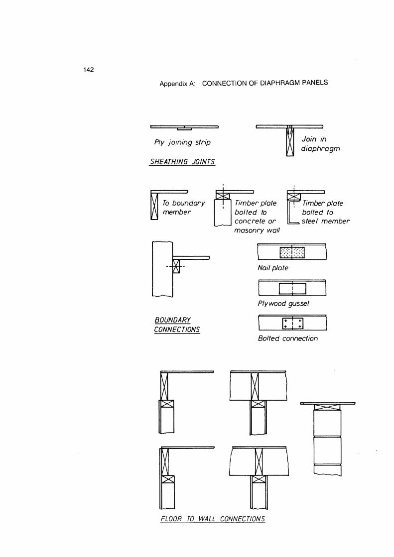
142
Ply joining strip
SHEATHING JOINTS
Join in diaphragm
To boundary member
BOUNDARY CONNECT IONS
Timber plate bolted to concrete or masonry wall
Timber plate bolted to steel member
Nail plate
Plywood gusset
Bolted connection
FLOOR TO WALL CONNECTIONS
Appendix A: CONNECTION OF DIAPHRAGM PANELS