Honeywell Switch Catalog
213
Product Catalog SENSING AND CONTROL Switches and Custom Controls
-
Upload
hammondelec -
Category
Documents
-
view
8.305 -
download
24
Transcript of Honeywell Switch Catalog

Product Catalog
SENSING AND CONTROL
Switches and Custom Controls

! WARNINGMISUSE OF DOCUMENTATION• The information presented in this catalogue is for
reference only. DO NOT USE this document as productinstallation information.
• Complete installation, operation and maintenanceinformation is provided in the instructions supplied witheach product.
Failure to comply with these instructions could result indeath or serious injury.
! WARNINGPERSONAL INJURY• DO NOT USE these products as safety or emergency stop
devices or in any other application where failure of theproduct could result in personal injury.
Failure to comply with these instructions could result indeath or serious injury.
! WARNINGIMPROPER INSTALLAION• Consult with local safety agencies and their requirements
when designing a machine-control link, interface and allcontrol elements that affect safety.
• Strictly adhere to all installation instructions.Failure to comply with these instructions could result indeath or serious injury.

1www.honeywell.com/sensing
Introduction - How to use this catalogue .....................................................Page 2
Industrial Electromechanical Limit Switches ................................................ Page 5Selection Guide .............................................................. Page 6Limit Switch Application Information .................................... Page 8Global Limit Switches .................................................... Page 10Compact Limit Switches ................................................. Page 21Precision Limit Switches ................................................. Page 34Heavy Duty Limit Switches ............................................... Page 46Hazardous Location Switches ........................................... Page 57Levers for Limit Switches ................................................ Page 71
Power Relays .................................................................................... Page 74
Electromechanical Safety Switches.......................................................... Page 79Selection Guide ............................................................ Page 80
Basic Switches ................................................................................. Page 103
Pressure Switches ............................................................................. Page 113
Environment Sealed, Hermetically Sealed and Manual Switches .................... Page 119Sealed Switches .......................................................... Page 119Manual Switches ......................................................... Page 139
Manual Switches and Pushbuttons ........................................................ Page 165Selection Guide ........................................................... Page 166AML Series Advanced Manual Line Switches ........................ Page 168MML Series Miniature Manual LIne Switches ....................... Page 171
Custom Switches and Assemblies .......................................................... Page 173
Vehicle Controls ............................................................................... Page 175Custom Controls ........................................................... Page 175Hour Meters ................................................................ Page 176Key Switches .............................................................. Page 184Push/Pull Switches ....................................................... Page 185Shifters ..................................................................... Page 186Proportional Retarders ................................................... Page 187Turn Signals ............................................................... Page 188Lighting Products ......................................................... Page 189Other Vehicle Controls ................................................... Page 194
Precision Aerospace .......................................................................... Page 195
Sensing and Control Product Overview .................................................... Page 196
New Technologies and Emerging Capabilities ........................................... Page 198
Index ............................................................................................ Page 199
Sales and Service ............................................................................. Page 210
CONTENTS

2www.honeywell.com/sensing
INTRODUCTION
HONEYWELL SWITCHES AND CONTROLS
Honeywell switches and controls provide a wide selection of solutions.This catalogue contains our most popular offerings. To view ourcomplete range of products, visit our web site athttp://www.honeywell.com/sensing.
Honeywell is a worldwide leader in advanced switching and sensingtechnology. Our reputation for technology, quality and reliability issecond to none. We have more than 60 years of experience; andextensive knowledge of a wide range of industries and an extensivecustomer service and support network.
Honeywell manufactures the original MICRO SWITCH brand switches:micro switches, toggle and rocker switches, hermetically andenvironmentally sealed switches, and relays and limit switches. Honeywellswitches are aimed at providing an enhanced level of performance andquality.
Honeywell HOBBS brand is well known worldwide for the development ofquality electromechanical products. The HOBBS brand includes hourmeters and battery discharge indicators, key switches, off-highway
vehicular lighting, shifters, pressure and vacuum switches, and customproduct development and rapid prototyping technology.
Honeywell’s aerospace switches and controls are designed for the moststringent industry requirements. The portfolio consists of position, force,torque and pressure sensors, indicators and actuators. In addition toour standard product offering, Honeywell offers repair and overallservices for highly engineered aerospace controls.
Honeywell continues to strive to solve customers’ needs. Whether youneed custom solutions or standard off-the-shelf products, our extensivein-house design, manufacturing and environmental testing capabilitiesoffer solutions and alternatives to meet your needs.
3www.honeywell.com/sensing
INTRODUCTION
How to use this catalogueFor each referenced listing, key specification parameters, descriptionsand mounting drawing information are presented. These illustrate ourcapabilities while the specifications allow easy differentiation betweensimilar products.
There are, of course, many more product options available. Full productspecification may be accessed on our website (www.honeywell.com/sensing). At the Home page enter the catalog listing in the SEARCH boxand click GO! This will take you directly to the interactive catalogue/specification search tables for this listing. Alternatively select and click theinteractive catalogue icon on the Home page and then choose a productcategory against which to do a specification search.
Also on the website you can access installation instructions, applicationnotes, Frequently Asked Questions (FAQs), selection guides andadditional technical information.
Mounting dimensionsMounting dimensions shown in each product section are for referenceonly. For exact information, request an engineering drawing from yournearest Honeywell sales office or visit our website and access it throughthe interactive catalogue. Where dual dimensions are shown onmounting drawings, the first or upper one is millimetres (mm) and thesecond or lower is inches (in). Where single dimensions are shown,they are millimetres (mm), unless otherwise stated.
To order these productsSimply contact your local Honeywell Sales Representative, yourHoneywell Distributor or your local Honeywell office.
If you need a product not listed in this catalogueOne of Honeywell’s strengths is in packaging of sensing technology tomeet customer needs. Honeywell provides many variations of our basicswitches and sensors. For more information, either browse the fullinteractive catalogue available on our website, or telephone the followingnumbers:
USA 1-800-537-6945/1-815-537-6945UK +44 (0)1698 481 481 Germany +49 69 8064 444France +33 1 60 19 80 40 Italy +39 02 92146 450/456
More information on Honeywell Sensing & Control products and how tocontact us can be found on our website.
Select the right product – select the right supplierDelivering excellence in system critical sensingsolutionsA system is critical if the quality, reliability, delivery and customer serviceassociated with a component part is essential to the performance of theoperation or end product. If a sensor or a switch is critical to theperformance, cost effectiveness, delivery or safety of a product oroperation then it’s system critical. It is therefore a defining element in theperformance of the system under whatever conditions apply. Failure ofthe component - or failure of delivery of the component - results in lostproductivity, increased costs or a catastrophic event such as ashutdown. Therefore selecting the right product is essential. It canmake the difference between success and failure.
Honeywell Sensing and Control – delivering excellenceTo select the right product, first select the right supplier. To deliver the rightproducts for our customers’ needs we listen to them to understand theirneeds. Using techniques such as “Voice of the Customer and “ConceptEngineering” we make sure that the products and solutions we deliver are theright ones. As part of Honeywell we can use local knowledge andunderstanding combined with global expertise and resources to achieve this.We can deploy many key technologies to bring innovative solutions tocustomers’ problems.
Our products are manufactured to work well and to last. We use Six SigmaPlus productivity to ensure this is the case. We have award winningmanufacturing facilities around the world and recognised world classbusiness excellence in manufacturing and supply chain management todeliver on time, anywhere in the world.
Our e-business approach offers instant access to product information,technical support and application knowledge through out Internet site.Check out our powerful interactive catalogue that can search and find theright products for customers’ needs and deliver a drawing ready forincorporation in a CAD system direct to your desk.
And of course, we manage our whole business for the benefit of ourcustomers, using an acknowledged world-class business excellenceapproach that incorporates Six Sigma principles.
Expanded Product LinesAs well as many new and innovative switches, this catalogue includes anexpanded range of Pressure and Position Sensors, previously knownunder the Clarostat, NEI and Electrocorporation brand names.

4www.honeywell.com/sensing

5www.honeywell.com/sensing
Industrial ElectromechanicalLimit SwitchesHoneywell offers an advanced line of heavy duty limit switches and a wideselection of application-proven enclosed switches (precision snap-actingswitches sealed in rugged metal housing). Sealed versions keep outmoisture and other contaminants. Our products meet or exceed criticalstandards allowing for global use. Our rugged switches are suitable for usein harsh-duty, wash-down environments. We offer a variety of circuitry,terminations and actuators to ensure that you can match your choice ofswitch to your application.
Limit and enclosed switches are the cost effective switches of choice fordetecting objects which can be touched. When an object comes in contactwith an actuator, the switch operates. Rugged and dependable, theseswitches are offered in a variety of sizes, with different seals, enclosures,actuation, circuitries and electrical ratings. Enclosed switches are knownfor enhanced precision and low cost. Limit Switches are especiallyrugged and well sealed. Explosion proof switches are designed for usein hazardous locations.
The Honeywell switches featured here are all proven in a broad range ofpotential Industrial applications - machine tools, packaging machinery,lifting gear, presses and construction machinery.
More information about our complete product range - and the depth ofproduct available within each product line - can be found on our interactivecatalogue at www.honeywell.com/sensing.
MICRO SWITCH Brand productsHoneywell has been at the forefront of switching technology since we werethe first to develop the precision snap-action switch more than 60 years ago.Ever since we introduced the Micro Switch Brand Products in 1937, we havebeen recognized as the performance standard that all other switches aremeasured against. We continue in that tradition by constantly improving thetechnology, cost-effectiveness, and delivery of these hardworking, versatileelectromechanical switches.
LIMIT SWITCHES
! WARNING
IF USED IN APPLICATIONS CONCERNING HUMAN SAFETY• Only use NC direct opening (“positive opening”/ “positive
break”) contacts, identified by the symbol .• Do NOT use flexible / adjustable actuators. Only use
actuators designed for safety applications.• Do NOT defeat, tamper, remove, or bypass this switch.• Hazardous voltage, disconnect power before servicing.• Strictly adhere to all installation and maintenance
instructions.• Consult with local safety agencies and their requirements
when designing a machine-control link, interface and allcontrol elements that affect safety.
Failure to comply with these instructions could result indeath or serious injury.

6www.honeywell.com/sensing
Selection Guidefor Limit Switches
EVN2000
EX
GXE
CX
BF
14CE100
LSX/BX
SZL-VL
GLA
GLA GLE
GLC GLD
LIMIT SWITCHES
GLOBAL
PRECISION
HAZARDOUS LOCATION
Dimensions
EV
N20
00
DC13, Q300
SZ
L-V
L
6496,0 x 28,0 x 39,0 [3.8 x 1.10 x 1.51]
5 A Resistive - 125, 250 Vac
0.4 A Resistive 125 Vdc
EN
5004
1 (G
LA)
1, 4, 12, 13102,9 x 42,0 x 42,0[4.05 x 1.65 x 1.65]
AC15 A600 (A300 DPDT)
DC13
EN
5004
7 (G
LC/D
/E)
66
GLC/E1, 4, 12, 13
GLD1, 2, 12
77,0 x 30,0 x 30,5[3.03 x 1.18 x 1.20]
AC15 A600 Plastic,
A300 Metal Housing
DC13S
L1 6728.4 x 44.2 x 18,0
[1.12 x 1.74 x 0.71]
14C
E91
4CE
24C
E92
4CE
LS (-L)
67(20 mm conduit)
1, 3, 4, 6, 13(½ in conduit)
94,0 x 40,6 x 58,42[3.7 x 1.6 x 2.3]
BF 67
44,5 x 73,5 x 30,2 [1.75 x 2.9 x 1.19]
BZ
E/D
TE
1 (E6)1, 3 (V6)
44,4 x 77,2 x 25,4[1.75 x 3.04 x 1.0]
E7 50 (standard),
65 (boot seal)45,2 x 76,4 x 25,4[1.67 x 3.0 x 1.0]
BA
F/D
TF
1, 3, 4, 13;1 (-2RQ9)
54,8 x 101,6 x 33,0[2.16 x 4.0 x 1.3]
HD
LS 1, 3, 4, 4X, 6, 6P,
12, 13
HD
LS
Ful
ly p
otte
d 1, 4, 6, 6P, 12, 13(connector)
1, 4, 6, 6P, 12(cable)
HD
LS
S
tain
less
st
eel Stainless
Steel1, 3, 3R, 4, 4X, 6,
6P, 12, 13123,0 x 47,7 x 61,9
[4.9 x 1.9 x 2.4]
14C
E10
0
65 (standard), 67 (boot seal)
1, 3 (standard),1, 3, 4, 12, 13
(boot seal)
49,0 x 40,0 x 16.0[1.93 x 1.57 x 0.63]
GX
E
66/6760,0 x 52,0 x 25,0[2,36 x 2.05 x 1.0]
EX 1, 7, 9
65,0 x 93,0 x 52,0[2.56 x 3.66 x 2.0]
CX 1, 3, 4, 4X, 6, 6P,
7, 9, 13102,0 x 102,0 x 145,0
[4.0 x 4.0 x 5.71]
LSX
1, 3, 4, 6, 7, 9, 13
BX 67
Pre
cisi
on
1, 2, 3, 3R, 4, 6, 6P, 12 (boot
seal), 13
10 A - 125 Vac,20 A - 125 Vac
IECIP
AC
CE
C-U
L
UL
CS
A
Thermoplastic/Metal
Series
Glo
bal
Plastic
Co
mp
act
Hea
vy D
uty
Haz
ard
ou
s L
oca
tio
n
Approvals
66, 67, 68
Sealing
NEMA(USA)
GL
Housing Material
Die cast base/Plastic cover
66 (standard), 67 (boot seal)
Electrical Rating
5 A - 125, 250 Vac
5 A - 125, 250 Vac
10 A - 250 Vac
Height x Width x Depthmm[in]
Up to 20 A @ 125, 250 or 480 Vac
121,0 x 76,0 x 73,0 [[4.8 x 3.0 x 3.0]
SDPT:106,7 x 41,1 x 62,0
[4.2 x 1.6 x 2.4]DPDT:
119,1 x 47,8 x 62,0[4.7 x 1.9 x 2.4]
44,0 x 40,0 x 16,0 [1.73 x 1.57 x 0.63]
49,0 x 40,0 x 16,0[1.93 x 1.57 x 0.63]
SPDT (NEMA A600),DPDT (NEMA B600)
10 A Thermal: SPDT (NEMA A600),DPDT (NEMA B600)
10 A - 120, 240, 480 Vac
11 A - 125 Vac,5 A - 125 Vac
1 A - 125 Vac,15 A - 125 Vac
1 A - 125 Vac,15 A - 125 Vac
AC14 D300,DC13 R300
AC15,DC13
Up to 20 A @ 125, 250 or 480 Vac
Metal
1, 12, 1366, 67
DC
AC15, A300
67
3, 4, 13
(-L)
1, 3, 4, 13
1, 3, 4, 6, 7, 9, 13
CC
C
GLL 65 1, 12, 13
10 A Thermal,300 Vac
10 A Thermal,250 Vdc
62,0 x 30,5 x 31,0[2.44 x 1.20 x 1.22]
95,3 x 28,7 x 22,0[3.75 x 1.13 x 0.87]
–
–
–
–
–
–
–
–
–
–
–
–
BZE/DTEE7
BAF/DTF

7www.honeywell.com/sensing
HDLS
LS
SL1
24/924CE
14/914CE
LIMIT SWITCHES
HEAVY DUTY
COMPACT
StainlessSteelHDLS
Termination
Make Before Break
1NC/1NO
2NC/2NO
1NC/1NO
2NC/2NO
1NC1NC/ 1NO
1NC/1NO
2NC/1NO
2NC/2NO
3NC/1NO
4NC
-25[-13]
85 [185]
Cable gland/cord grip
Insulation Displacement Termination
10
-20[-4]
60[140]
Flexible cable gland/cord grip
Gold plated silver contacts standard
11
-25[-13]
85[185]
14
-40 85[185]
16
-10[-14]
70[160]
Cord grip
70[221]
105[221]
-29[-20]
71[160]
Conduit
-32[-25]
71[160]
Conduit
-32[-25]
71[160]
ConduitPrecise operation.Low temperature versions available
36
-30[-22]
70[158]
Conduit
-32[-25]
71[160]
ConduitRugged housed precise
operation42
-12 [-10];-40 [-40]
121[250]**
Conduit
Low temperature and Fluorocarbon Seal versions available.
Wide variety of actuator styles.
Cable and connector available.
46
-12[-10]
Connector121 [250];
Cable version
105 [221]
Cable or Connector
Switch cavity is epoxy filled
53
-12 [-10]-40 [-40]
121 [250]**
Conduit, CableCorrosion resistant
stainless steel housing55
0[32]
70 [158]
Preleaded cable
Miniature size
-20 [-4]
75[167]
Preleaded cable
59
-40 [-40]
71[160]
ConduitHigh temperature option
(400 °F for 100 Hr)60
See Catalog for details
85[185]
ConduitOptional 4-20 mA
analog output64
See Catalog for details
See Catalog for details
ConduitWide variety of
actuators, circuitry and termination options
66
-40[-40]
See Catalog for details
ConduitATEX approvals for
European use66
*HDLS, LSX and BX Series are available with the following Switching Options: NC/NO snap-action, Maintained; additional data 2NC/2NO snap-action, Maintained; 2NC/2NO snap-action, Center Neutral; 2NC/2NO snap-action, Sequential
CX, LSX, BX also available with 1NC Direct Acting
Cable,Quick Connect
0[32];
low temp option to
-30°
70[221]
0[32]
Pag
e N
umbe
rGold Contacts
(Low Energy
Options)
Low and high temperature options
available.Direct acting contacts
Low and high temperature options
available.Superior Sealing (IP 68)
Wide variety of actuator styles and circuitry
options
°C[°F]
From
Switching Options*
Cable,Quick Connect
Break Before Make
Slow Action
Snap Action
Operating Temperature
23
26
Conduit
**Refer to catalog for
21
29
34
41
58
[-40]
To
Special Features
Cost effective solution
Precise operation
Miniature size
-10[14]
80 [176]
2NC
ConduitLowest costswitch option 20

8www.honeywell.com/sensing
LIMIT SWITCHES
Proper application of limit switchesThe following are guidelines for the correct application of Limit Switches.Never use the Limit Switch as a physical end stop. Mechanical damage orincorrect operation may occur if this is done. Always ensure that themechanical actuator is protected from excessive mechanical shock. Neverrelease the actuator suddenly - gradual actuation and release will ensure thatstress on the mechanics of the switch is kept to a minimum. This has theadded benefit that the switch life will be improved. The diagrams illustratehow to actuate your limit switch for optimum performance.
Standards and Electrical ratingIEC/EN 60947-1 explains the general rules relating to Low Voltageswitchgear and controlgear. The purpose of this standard is toharmonize as much as possible the product performance and testrequirements for equipment where the rated voltage does not exceed1,000 Vac or 1,500 Vdc.
IEC 60947-5-1 is part 5 of the general rules which relates to Control-circuit devices and switching elements, where rated voltage does notexceed 1,000 Vac or 600 Vdc. There are special requirements for controlswitches with direct opening operation. These switches are marked onthe outside with this symbol:
The Contact Element form defines the configuration and number ofcontacts within the switch.
Form Za – both contact elements have the same polarity
Form Zb – the two contact elements are electrically separated.
The Utilization Category defines the type of current carried – ac or dc –and the typical application where the switch is used.
The contact rating Designation relates to the Utilization Categories anddefines the conventional thermal current Ith (a) rated operational current Ie(A) at rated operational voltages Ue and the VA rating.
ActuatorsA range of actuators is available for limit switches. Illustrations of actuatortypes available from this catalogue are shown at the beginning of eachproduct family. Other actuators may be available - for more informationplease contact your local Honeywell office.
For limit switches with pushrod actuators, the actuating force should be applied asnearly as possible in line with the pushrod axis.
Cam or dog arrangements should be such that the actuator is not suddently releasedto snap back freely.
Operating mechanisms for limit switches shoud be so designed that, under anyoperating or emergency conditions, the limit switch is not operated beyond itsovertravel limit position. A limit switch should not be used as a mechanical stop.
For limit switches with lever actuators, the actuating force should be applied asnearly perpendicular to the lever as practical and perpendicular to the shaft axisabout which the lever rotates.
WRONG WRONG
RIGHT FIXED STOP
RIGHT
WRONG WRONG
RIGHT RIGHT
over-riding
cam
over-riding
cam
WRONG WRONG
RIGHT RIGHT
free position
free position
interference
end ofovertravel
operatedposition
end ofovertravel
WRONG
RIGHT
over-riding
non-over-riding
Roller lever Top rollerlever
Adjustableroller lever
Top pinplunger
Top pinplunger,boot seal
Top rollerplunger
Top rollerplunger,boot seal
Top rollerplunger,
perpendicular
Top rollerplunger,
perpendicular,boot seal
Ball bearingplunger
Sideroller plunger
Sidepin plunger
Roller lever Yoke lever Rod lever Wobble head

9www.honeywell.com/sensing
LIMIT SWITCHES
A Note on Degrees of ProtectionIP ClassificationThe IEC 529 standard describes a system for classifying the degree ofprotection provided by the enclosures of electrical equipment. The level ofprotection given by the enclosure is indicated by the IP code. This codesystem uses the letters ‘‘IP’’ (International Protection) followed by up to fourdigits. Normally only the first two digits are used.
IP 1st Digit 2nd Digit 3rd Digit 4th Digit
The first digit is numerical and indicates the level of protection within theenclosure against the ingress of solid foreign objects and access tohazardous parts by persons.
The second digit is also numerical and indicates the level of protectionagainst the ingress of WATER into the enclosure.
The third digit is a letter and indicates a higher level of protection forpersons against access to hazardous parts.
The fourth digit is also a letter and is used in exceptional cases forsupplementary information.
If the first or second digit is not required to be specified, then it is replacedby the letter ‘‘X’’ (‘‘XX’’ if both digits are not required). While the tablesbelow serve as a guide to the level of protection, Honeywell recommendsthat customers refer to the full official IEC specification for the exactdefinitions. If in doubt about the degree of protection required for a particularapplication, please consult your local Honeywell office.
Note:
The IEC 529 standard does not relate to protection against rust, corrosion,icing or corrosive solvents (e.g. cutting fluids) and that product coded IP 67may not necessarily meet IP 66 requirements.
First Digit Protection against ingress of solid objects
IP TEST
0 no protection
1 protected against solid objects with a diameter greater than 50 mm
2 protected against solid objects with a diameter greater than 12 mm
3 protected against solid objects with a diameter greater than 2.5 mm
4 protected against solid objects with a diameter greater than 1 mm
5 protected against dust-limited ingress (no harmful deposit)
6 totally protected against dust
Second Digit Protection against ingress of water
IP TEST
0 no protection
1 protected against vertically falling drops of water
2 protected against vertically falling drops of water when the enclosure istilted at an angle up to 15 degrees
3 protected against water sprayed at an angle of 60 degrees from the vertical
4 protected against splashing water from all directions – limited ingress (noharmful effects)
5 protected against low pressure jets of water from all directions – limitedingress permitted
6 protected against powerful jets of water from all directions – limitedingress permitted
7 protected against the effects of temporary immersion in water
8 protected against the effects of continuous immersion in water
NEMA Classification (USA)NEMA (National Electrical Manufacturer’s Association) prepares standardswhich define a product, process or procedure with reference to one or moreof the following: nomenclature, composition, construction, dimensions,tolerances, safety, operating characteristics, performance, quality, electricalrating, testing and the service for which designed. This standard providesdegrees of protection for Enclosures for Electrical Equipment (1000 VoltsMaximum) similar to that of the IEC 529 standard. The reference standardherein reflects the latest data in the NEMA Standards Publication when thisinformation went to print. Please check the most current NEMAStandards Publication for the latest information.
Non-hazardous locations
Type 1 enclosures are intended for indoor use primarily to provide adegree of protection against contact with the enclosed equipment.
Type 3 enclosures are intended for outdoor use primarily to provide adegree of protection against windblown dust, rain, sleet, and external iceformation.
Type 4 enclosures are intended for indoor or outdoor use primarily toprovide a degree of protection against windblown dust and rain, splashingwater, and hose-directed water.
Type 4X enclosures are intended for indoor or outdoor use primarily toprovide a degree of protection against corrosion, windblown dust and rain,splashing water, and hose-directed water.
Type 6 enclosures are intended for indoor or outdoor use primarily toprovide a degree of protection against the entry of water during occasionaltemporary submersion at a limited depth.
Type 6P enclosures are intended for indoor or outdoor use primarily toprovide a degree of protection against the entry of water during prolongedsubmersion at a limited depth.
Type 12 enclosures are intended for indoor use primarily to provide a degreeof protection against dust, falling dirt, and dripping noncorrosive liquids.
Type 13 enclosures are intended for indoor use primarily to provide a degreeof protection against dust, spraying water, oil and noncorrosive coolant.
Note:
Enclosures are based, in general, on the broad definitions outlined in NEMAStandards. Therefore, it will be necessary to ascertain that a particularenclosure will be adequate when exposed to the specific conditions thatmight exist in intended applications.
Except as might otherwise be noted, all references to products relative toNEMA enclosure type are based on Honeywell evaluation and Underwriter’sLaboratory (UL) tested. This NEMA Standards Publication does test forenvironmental conditions such as corrosion, rust, icing, oil, and coolants.The IEC 529 does not, and does not specify degree of protection againstmechanical damage of equipment. For this reason, and because the tests andevaluations for other characteristics are not identical, the IEC EnclosureClassification Designations cannot be exactly equated with NEMA EnclosureType Numbers.

1 0www.honeywell.com/sensing
GLOBAL LIMIT SWITCHES
EVN2000 SeriesEN 50047Global LimitSwitches
The EVN2000 series limit switch is an innovative product which has been developed to address aneed highlighted by Original Equipment Manufacturers (OEM), where “Ease of Wiring” is required.With the new design there is no need for access to the inside of the housing and therefore thehousing cover, cover screws and gasket become obsolete. Furthermore, the integrated cablegland eliminates the need for additional conduit or cable gland hardware. All Normally Closed (NC)contacts are Direct Opening.
Mechanical life: 10 millionSealing: IP 66/67, NEMA 1, 12, 13Operating temperature: -25 °C to 85 °C [-13 °F to 185 °F]Approvals: IEC/EN 60947-5-1
EN 60529EN81-1
AC15 A300 DC13 Q300
UL, CEHousing material: PlasticTermination: Insulation Displacement Terminals (IDT)Switching options: SPDT Single Pole, Double Throw,
Snap action contacts (1NC/1NO)
OPTIONS
Side rotary plastic roller
CAT. LISTINGEVN2000A
Top pin plunger
CAT. LISTINGEVN2000B
Top roller plunger, perpendicular
CAT. LISTINGEVN2000D
Operating characteristicsActuator Operating Free Pretravel Travel to Overtravel Differential Operatingtype torque/force position positive opening travel point
(OF) (FP) (PT) (PO) (OT) (DT) (OP)Siderotary 0,120 N m 0° 25° 45° 45° 12° 25°EVN2000A [1.10 lb in]Top pinplunger 16,0 N 20,0 mm 2,0 mm 3,5 mm 4,0 mm 1,0 mm 18,0 mmEVN2000B [3.60 lb] [0.79 in] [0.08 in] [0.14 in] [0.16 in] [0.04 in] [0.71 in]Top rollerplunger, 16,0 N 30,0 mm 2,0 mm 3,5 mm 4,0 mm 1,0 mm 28,0 mmparallel [3.60 lb] [1.18 in] [0.08 in] [0.14 in] [0.16 in] [0.04 in] [1.10 in]EVN2000CTop rollerplunger, 16,0 N 30,0 mm 2,0 mm 3,5 mm 4,0 mm 1,0 mm 28,0 mmperpendicular [3.60 lb] [1.18 in] [0.08 in] [0.14 in] [0.16 in] [0.04 in] [1.10 in]EVN2000D
Actuators
Top roller plunger, parallel
CAT. LISTINGEVN2000C

1 1www.honeywell.com/sensing
VL SeriesGeneral Purpose CompactLimit Switches
The new economical SZL-VL Series miniature type limit switches arespecially designed for potential applications of small mounting space.These miniature switches are ideal for OEM machinery which requires arugged and reliable limit switch that is capable of being mounted in spacerestricted applications. A wide range of actuators and optional neon lampindicators add additional flexibility. A special pre-molded flexible cablegland allows for fast and simple wiring termination.
Mechanical life: up to 10 million operationsSealing: IP 64Operating temperature: -20 °C to 60 °C [-4 °F to 140 °F]Approvals: UL, C-UL, CETermination: Cable glandContacts: Gold plated silverElectrical ratings: 250 Vac 125 Vdc max.Ampere rating: 5 A @ 250 Vac max./0.4 A @ 125 Vdc max.Switching options:SPDT Single Pole, Double Throw, Double break
(1NC/1NO)
VL3 4
21NO
NC
NO
NC
Side rotary actuated switchesPretravel max. (PT): 20°Overtravel min. (OT): 75°Differential travel max. (DT): 10°
OPTIONS
Roller lever
(Roller can be
in any position
(with hexagonal
7 .276 in depthmounting holes
41.2±.08
36.2±0.8nylon roller
R30 M4 arm
56±0.3
21±0.2
28
M3x6cover screw
M4 arm fixing nut
12.5
.402
18.5
64
2-M5 (P=0.8)tapped
14
7.5±0.2
15.1
38.1
25
2-M3x23
20.4±0.3
PT 20 ̊max
cover screw
(Standard type)
18 dia.x7
through 360˚)
.827±.008
1.102
2.205±.012
.492
holes)
rotated and locked
1.622±.031
1.425±.031
10.2
.728
.803±.012
2.520
.551
1.5
.984.594
.295±.008
mounting holes
2-M5 (P=0.8)tapped
mounting holes
2-4.1 dia.+0.2
-0
fixing screw
mounting holes
.161 dia.+0.008
-0
Operating torque max.: 5,88 N [1.32 lb]
CAT. LISTINGSZL-VL-A
Roller lever, adjustable
hexagonal holes
Arm fastening plate
Mounting metal
M4 arm fasteningplate screw with
Adjustable length of arm(30-70)
.402
2.0
(Roller can be rotatedand locked in anyposition through 360˚)
2-M3x23cover screw
M3x6cover screw
12.5
56±0.3
21±0.2
28
7 .276 in depthmounting holes
2-M5 (P=0.8) tapped
18.5
64
14
7.5±0.215.1
20.4±0.325
(46.4)
PT 20˚max
(Standard type)1.102
.827±.008
.492
2.205±.012
18 dia.x7 nylon rooler
hexagonal holesplate screw withM6 arm fastening
10.2
.728
2.520
.551
.295±.008
(1.827)
.984
.594.803±.012
2-M5 (P=0.8) tappedmounting holes.079
mounting holes2-4.1 dia.
+0.2 0
1.122±.031
1.319±.03133.5±0.8
1.878±.03147.7±0.8
42.7±0.81.681±.031
28.5±0.8
mounting holes
.161 dia.+0.008 -0
Operating torque max.: 3,35 N to 7,84 N [0.75 lb to 1.76 lb]
CAT. LISTINGSZL-VL-B
GLOBAL LIMIT SWITCHES
Actuators

1 2www.honeywell.com/sensing
VL SeriesSide rotary actuated switches (continued)
Adjustable rod
7 .276 in depthmounting holes
hexagonal holes
.217
36.3±0.8
44.9
(Roller can be rotatedand locked in any
position through 360˚)
M4 rod fastening platescrew with hexagonal holes
Rod fastening plate
12.5
56±0.3
21±0.2
28
Adjustable lenght of rod(30-118)
.402
18.5
64
14
2-M5 (P=0.8) tapped
7.5±0.215.1
20.4±0.325
Rod mounting metal
M6 mounting rodfastening screw with
2-M3x23cover screw
M3x6cover screw
(44.9)
PT 20 ̊max
(Standard type)
5.5
2.6 .102 dia. rod
.492
2.205±.012
1.102
.827±.008
1.768
1.429±.031
10.2
.728
2.520
.551
.295±.008
(1.768).984
.594.803±.012
2-M5 (P=0.8) tappedmounting holes
mounting holes2-4.1 dia.
+0.2 0
mounting holes.161 dia.
+0.008 -0
Operating torque max.: 2 N to 7,84 N[0.45 lb to 1.76 lb]
CAT. LISTINGSZL-VL-C
Plunger actuated switchesPretravel max. (PT): 1,5 mm [0.060 in]Overtravel min. (OT): 4,0 mm [0.158 in]Differential travel max. (DT): 0,7 mm [0.028 in]Operating force max. (OF): 8,83 N [2 lb]
Top pin plunger
mounting holes
.402
2-M3x23cover screw
2-4.1+0.2
mounting holes
2-M5 (P=0.8) tapped7 .276 in depth
M3x6cover screw
64
14
7.5±0.215.1
25
20.4±0.3
.118
26.5
56±0.3
21±0.2
28
stainless steel plunger
mounting holes2-M5 (P=0.8) tapped
(Standard type)
7. 276 dia.
dia.
3
1.043
2.205±.012
1.102
.827±.008
10.2
.803±.012
4
2.520
.984
.594.295±.008
.157
.551
0
PT 1.5 max
.161+0.008
mounting holes dia. -0
CAT. LISTINGSZL-VL-D
Top roller plunger
56±0.3
38
14.8
12.5 dia.x3.8stainless steel roller
21±0.2
28
2-M3x23cover screw
M3x6cover screw
.402
20.4±0.3
.157
64
14
7 .276 in depthmounting holes
2-M5 (P=0.8) tapped
mounting holes2-M5 (P=0.8) tapped
15.1
25
7.5±0.2
(Standard type)
.583
1.496
2.205±.012
1.102
.827±.008
10.2
.803±.012
4
2.520
.551
.295±.008.594
.984
mounting holes2-4.1 dia.
+0.2 0
PT 1.5 max
mounting holes.161 dia.
+0.008 -0
CAT. LISTINGSZL-VL-H
GLOBAL LIMIT SWITCHES

1 3www.honeywell.com/sensing
Plunger actuated switches (continued)
Cross roller plunger
.402
M3x6cover screw
12.5 dia.x3.8stainless steel roller
2-M3x23cover screw
21±0.2
28
56±0.3
38
14.8
7.5±0.215.1
25
20.4±0.3
.157
64
14
mounting holes
2-M5 (P=0.8) tapped7 .276 in depth
mounting holes2-M5 (P=0.8) tapped
(Standard type)
.583
1.496
2.205±.012
.827±.008
1.102
10.2
4
.803±.012
2.520
.551
.295±.008
.984
.594
mounting holes2-4.1 dia.
+0.2 0
PT 1.5 max
mounting holes.161 -0 dia.
+0.008
CAT. LISTINGSZL-VL-E
Wobble actuated switchesPretravel max. (PT): 30 mm [1.18 in]Overtravel min. (OT): 20 mm [0.788 in]Operating force max. (OF): 0,88 N [0.2 lb]
Plastic rod, coil spring
.402
21±0.2
56±0.3
14
64
7.5±0.2
.157
28
20.4±0.3
25
15.1
5.8 dia.
3 dia.
Nylon rod
41.5
100±1.5
2-M3x23
M3x6cover screw
7 .276 in depthmounting holes
2-M5 (P=0.8) tapped
PT 50 max
(Standard type)
cover screw
1.634
3.937±.059
2.205±.012
1.102
.827±.008
10.2
.118
.228
.803±.012
4
2.520
.551
.295±.008
.984
.594
2-M5 (P=0.8) tappedmounting holes
mounting holes
2-4.1 dia.+0.2 0
mounting holes.161 dia.
+0.008 -0
CAT. LISTINGSZL-VL-F
Coil spring
.402
21±0.2
56±0.3
14
64
7.5±0.2
.157
28
20.4±0.3
25
15.1
.047 stainless
51.5
100±1.5
2-M3x23cover screw
M3x6cover screw
7 .276 in depthmounting holes
2-M5 (P=0
1.2 dia.
PT 30 max
(Standard type)
.8) tapped
2.028
3.937±.059
2.205±.012
.827±.008
1.102
10.2
steel wire
.803±.012
4
2.520
.551
.295±.008
.984
.594
2-M5 (P=0.8) mounting holes
mounting holes2-4.1
tapped
dia.+0.2 0
SZL-VL-G
mounting holes-0.161 dia.
+0.008
CAT. LISTINGSZL-VL-G
GLOBAL LIMIT SWITCHES

1 4www.honeywell.com/sensing
GLS SeriesGlobal LimitSwitches
GLOBAL LIMIT SWITCHES
SPDT DPDT SPDT DPDT SPDT DPDT SPDT DPDT SPDT DPDT SPDT DPDT SPDT DPDT
EN50041(GLA)
EN50047(GLC, GLD,
GLE)
0,120 N m[1.10 lb in]
0,165 N m[1.50 lb in]GLE only
11.5° 8°
EN50041(GLA)
EN50047(GLC, GLD,
GLE)
16,0 N[3.60 lb]
13,0 N[2.90 lb]GLE only
0,9 mm[0.035 in]
0,6 mm[0.024 in]
EN50041(GLA)
EN50047(GLC, GLD,
GLE)
16,0 N[3.60 lb]
13,0 N[2.90 lb]GLE only
0,9 mm[0.035 in]
0,6 mm[0.024 in]
EN50041(GLA)
EN50047(GLC, GLD,
GLE)
11,0 N[2.4 lb]
9,0 N[1.9 lb]
GLE only
EN50041(GLA)
EN50047(GLC, GLD,
GLE)
1,3 N[0.29 lb]
1,1 N[0.25 lb]GLE only
10° 7°
Actuatortype
Bodysize
26°
35,8 mm[1.41 in]
61,0 mm[2.40 in]
28,0 mm[1.10 in]
48,0 mm[1.89 in]
18,0 mm[0.71 in]
35,0 mm[1.38 in]
4,5 mm[0.18 in]
__
__
59°
49°
0,9 mm[0.035 in]
12°
0,9 mm[0.035 in]
1,7 mm[0.067 in]
1,3 mm[0.19 in]
8°
16°
18°
3,0 mm[0.12 in]
3,0 mm[0.12 in]
__
4,5 mm[0.18 in]
9,0 mm[0.35 in]
__
5,2 mm[0.205 in]
2,5 mm[0.10 in]
3,0 mm[0.12 in]
4,2 mm[0.165 in]
3,45 mm[0.14 in]
Overtravel(OT)
Differential travel(DT)
Operating point(OP)
Top roller lever
D
Lever typesA,
A*A, A*B,A4J
Top pin plunger
B
Top roller plunger
C
Operating torque/force(OF)
Pretravel(PT)
0,330 N m[2.90 lb in]
Wobble headE7B, E7D, K8B, K8C
16,0 N[3.60 lb]
16,0 N[3.60 lb]
9,5 N[2.10 lb]
0,1 N[0.90 in lb]
Free position(FP)
Travel topositive opening
(PO)
0° 55°26°
37,5 mm[1.48 in]
21,0 mm[0.83 in]
4,5 mm[0.18 in]
5,0 mm[0.20 in]
2,5 mm[0.10 in]
3,0 mm[0.12 in]
50,5 mm[2.00 in]
31,0 mm[1.22 in]
0°
65,2 mm[2.57 in]
39,25 mm[1.55 in]
__
__
4,5 mm[0.18 in]
5,0 mm[0.20 in]
8,3 mm[0.33 in]
6,9 mm[0.27 in]
Operating characteristics
IEC947-5-1/EN60947-5-1
Designation & Rated operational current Ie (A) VA
Utilization Category at rated operational voltage Ue rating
120V 240V 380V 480V 500V 600V Make Break
AC15 A600 6 3 1.9 1.5 1.4 1.2 7200 720
AC15 A300 6 3 - - - - 7200 720
AC15 B300 3 1.5 - - - - 3600 360
AC14 D300 0.6 0.3 - - - - 432 72
125V 250V
DC13 Q300 0.55 0.27 69 69
DC13 R300 0.22 0.1 28 28
Electrical ratings
GLS Series switches offer a complete range of CENELEC approvedproducts, and are suitable for most potential industrial applications.The standard product EN 50041 norm defines the switch mountingcentres as 30 mm x 60 mm and also defines the switchingcharacteristics of the side rotary head with fixed lever, top pin plungerand top roller plunger. This means that the switch can be interchangedin the application with other EN 50041 switches with mounting andswitching characteristics maintained. Honeywell offers many more headstyles and switching options.The miniature EN 50047 product range offers the user a choice ofplastic, metal and three conduit versions which are all mounting (20 mmx 22 mm) compatible with each other. The EN 50047 standard defineshow the switches are mounted and the switching characteristics for fixedside rotary lever, top pin plunger and top roller plunger.
Switching options:SPDT Single Pole, Double Throw, Snap action contacts (1NC/1NO)
13 14
2122
DPDT Double Pole, Double Throw Snap action contacts (2NC/2NO)
13 141211
23
21
2422
ActuatorsVibration (Actuator not fitted): 10 g conforming to IEC 68-2-6Shock (Actuator not fitted): 50 g conforming to IEC 68-2-27
Terminal marking to EN 50013
1 5www.honeywell.com/sensing
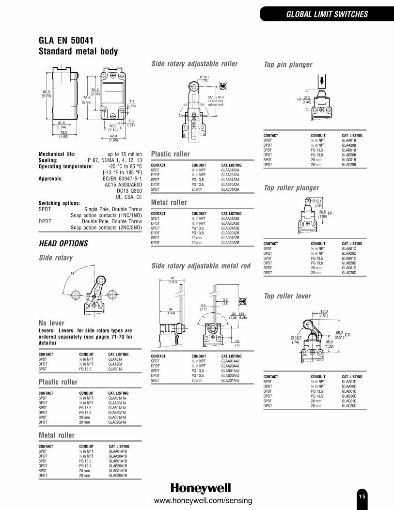
GLA EN 50041Standard metal body
Mechanical life: up to 15 millionSealing: IP 67, NEMA 1, 4, 12, 13Operating temperature: -25 °C to 85 °C
[-13 °F to 185 °F]Approvals: IEC/EN 60947-5-1
AC15 A300/A600 DC13 Q300 UL, CSA, CE
Switching options:SPDT Single Pole, Double Throw
Snap action contacts (1NC/1NO)DPDT Double Pole, Double Throw
Snap action contacts (2NC/2NO)
HEAD OPTIONS
Side rotary
No leverLevers: Levers for side rotary types areordered separately (see pages 71-73 fordetails)
CONTACT CONDUIT CAT. LISTINGSPDT ½ in NPT GLAA01ADPDT ½ in NPT GLAA20ASPDT PG 13,5 GLAB01A
Plastic rollerCONTACT CONDUIT CAT. LISTINGSPDT ½ in NPT GLAA01A1ADPDT ½ in NPT GLAA20A1ASPDT PG 13,5 GLAB01A1ADPDT PG 13,5 GLAB20A1ASPDT 20 mm GLAC01A1ADPDT 20 mm GLAC20A1A
Metal rollerCONTACT CONDUIT CAT. LISTINGSPDT ½ in NPT GLAA01A1BDPDT ½ in NPT GLAA20A1BSPDT PG 13,5 GLAB01A1BDPDT PG 13,5 GLAB20A1BSPDT 20 mm GLAC01A1BDPDT 20 mm GLAC20A1B
Side rotary adjustable roller
Plastic rollerCONTACT CONDUIT CAT. LISTINGSPDT ½ in NPT GLAA01A2ADPDT ½ in NPT GLAA20A2ASPDT PG 13,5 GLAB01A2ADPDT PG 13,5 GLAB20A2ASPDT 20 mm GLAC01A2A
Metal rollerCONTACT CONDUIT CAT. LISTINGSPDT ½ in NPT GLAA01A2BDPDT ½ in NPT GLAA20A2BSPDT PG 13,5 GLAB01A2BDPDT PG 13,5 GLAB20A2BSPDT 20 mm GLAC01A2BDPDT 20 mm GLAC20A2B
Side rotary adjustable metal rod
34(1.34)
41(1.61)
¯ 3,2(.13)
75˚75˚
15(.6)
32 - 134(1.26 - 5,28)
4,5(.17)
CONTACT CONDUIT CAT. LISTINGSPDT ½ in NPT GLAA01A4JDPDT ½ in NPT GLAA20A4JSPDT PG 13,5 GLAB01A4JDPDT PG 13,5 GLAB20A4JSPDT 20 mm GLAC01A4J
GLOBAL LIMIT SWITCHES
Top pin plunger
37,5(1.48)
FP
CONTACT CONDUIT CAT. LISTINGSPDT ½ in NPT GLAA01BDPDT ½ in NPT GLAA20BSPDT PG 13,5 GLAB01BDPDT PG 13,5 GLAB20BSPDT 20 mm GLAC01BDPDT 20 mm GLAC20B
Top roller plunger
FP
CONTACT CONDUIT CAT. LISTINGSPDT ½ in NPT GLAA01CDPDT ½ in NPT GLAA20CSPDT PG 13,5 GLAB01CDPDT PG 13,5 GLAB20CSPDT 20 mm GLAC01CDPDT 20 mm GLAC20C
Top roller lever
35,0(1.38)
65,2(2.51)Ø 18,7
(.74)
13,0(.51)
FP
CONTACT CONDUIT CAT. LISTINGSPDT ½ in NPT GLAA01DDPDT ½ in NPT GLAA20DSPDT PG 13,5 GLAB01DDPDT PG 13,5 GLAB20DSPDT 20 mm GLAC01DDPDT 20 mm GLAC20D

1 6www.honeywell.com/sensing
GLA EN 50041Standard metal body(continued)
Wobble, coil actuator
CONTACT CONDUIT CAT. LISTINGSPDT ½ in NPT GLAA01E7BSPDT PG 13,5 GLAB01E7BDPDT PG 13,5 GLAB20E7BSPDT 20 mm GLAC01E7BDPDT 20 mm GLAC20E7B
Coil wobble head, stainless steelspring actuator
CONTACT CONDUIT CAT. LISTINGSPDT ½ in NPT GLAA01E7D
Wobble, cat whisker
CONTACT CONDUIT CAT. LISTINGSPDT ½ in NPT GLAA01K8BSPDT PG 13,5 GLAB01K8B
Wobble, cat whisker, coilactuator
CONTACT CONDUIT CAT. LISTINGSPDT ½ in NPT GLAA01K8CDPDT ½ in NPT GLAA20K8CSPDT PG 13,5 GLAB01K8C
GLC EN 50047Standard metal body
24,75(0.97)
14,5(.57)
30(1.18)
conduit threadPG 13,5
22(.87)
20(.78)
3(.12)
2,15(.08)
R55
(2.16)
30,5(1.20)
3,5(0.138)
15,25(.600)
Mechanical life: up to 10 millionSealing: IP 66, NEMA 1, 4, 12, 13Operating temperature*: -40 °C to 85 °C
[-40 °F to 185 °F]Approvals: IEC/EN 60947-5-1
AC15 A300 DC13 Q300 UL, CSA, CE
Switching options:SPDT Single Pole, Double Throw
Snap action contacts (1NC/1NO)*Wobble actuator rated to -25 °C [-13 °F]
HEAD OPTIONS
Side rotary
°
Plastic rollerCONTACT CONDUIT CAT. LISTINGSPDT ½ in NPT GLCA01A1ASPDT PG 13,5 GLCB01A1A
Metal rollerCONTACT CONDUIT CAT. LISTINGSPDT ½ in NPT GLCA01A1BSPDT PG 13,5 GLCB01A1BSPDT 20 mm GLCC01A1B
GLOBAL LIMIT SWITCHES

1 7www.honeywell.com/sensing
GLC EN 50047Standard metal body(continued)
Side rotary adjustable
Plastic rollerCONTACT CONDUIT CAT. LISTINGSPDT ½ in NPT GLCA01A2ASPDT PG 13,5 GLCB01A2A
Metal rollerCONTACT CONDUIT CAT. LISTINGSPDT ½ in NPT GLCA01A2BSPDT PG 13,5 GLCB01A2BSPDT 20 mm GLCC01A2B
Side rotary adjustable, metal rod
34(1.34)
41(1.61)
¯ 3,2(.13)
75˚75˚
15(.6)
32 - 134(1.26 - 5,28)
4,5(.17)
CONTACT CONDUIT CAT. LISTINGSPDT ½ in NPT GLCA01A4JSPDT PG 13,5 GLCB01A4J
Top pin plunger
OP
DT
18±0,5
(.709)
Ø 9.9(.390)
CONTACT CONDUIT CAT. LISTINGSPDT ½ in NPT GLCA01BSPDT PG 13,5 GLCB01BSPDT 20 mm GLCC01B
Top roller plunger
31,01.22
FP
CONTACT CONDUIT CAT. LISTINGSPDT ½ in NPT GLCA01CSPDT PG 13,5 GLCB01CSPDT 20 mm GLCC01C
Top roller lever
Ø
39,2(1.54)
FP
CONTACT CONDUIT CAT. LISTINGSPDT ½ in NPT GLCA01DSPDT PG 13,5 GLCB01DSPDT 20 mm GLCC01D
Wobble, coil actuator
Mechanical life: up to 5 million
CONTACT CONDUIT CAT. LISTINGSPDT ½ in NPT GLCA01E7BSPDT PG 13.5 GLCB01E7BSPDT 20 mm GLCC01E7B
Wobble, cat whisker
Mechanical life: 5 million
CONTACT CONDUIT CAT. LISTINGSPDT ½ in NPT GLCA01K8ASPDT PG 13,5 GLCB01K8A
GLOBAL LIMIT SWITCHES

1 8www.honeywell.com/sensing
GLD EN 50047Double insulated plasticstandard body
24,75(0.97)
14,5(.57)
30(1.18)
conduit threadPG 13,5
22(.87)
20(.78)
3(.12)
2,15(.08)
R55
(2.16)
30,5(1.20)
3,5(0.138)
15,25(.600)
Mechanical life: See GLC sectionSealing: IP 66, NEMA 1, 2, 13Operating temperature*: -40 °C to 85 °C
[-40 °F to 185 °F]Approvals: IEC/EN 60947-5-1
AC15 A600 DC13 Q300 UL, CSA, CE
Switching options:SPDT Single Pole, Double Throw
Snap action contacts (1NC/1NO)*Wobble actuator rated to -25 °C [-13 °F]
HEAD OPTIONS
See GLC section for dimensionillustrationsSide rotaryPlastic roller/leverCONTACT CONDUIT CAT. LISTINGSPDT ½ in NPT GLDA01A1ASPDT PG 13,5 GLDB01A1A
Metal roller/leverCONTACT CONDUIT CAT. LISTINGSPDT ½ in NPT GLDA01A1BSPDT PG 13,5 GLDB01A1BSPDT 20 mm GLDC01A1B
Side rotary adjustablePlastic roller/metal leverCONTACT CONDUIT CAT. LISTINGSPDT ½ in NPT GLDA01A2ASPDT PG 13.5 GLDB01A2A
Metal roller/metal leverCONTACT CONDUIT CAT. LISTINGSPDT ½ in NPT GLDA01A2BSPDT PG 13,5 GLDB01A2BSPDT 20 mm GLDC01A2B
Side rotary adjustable metal rodCONTACT CONDUIT CAT. LISTINGSPDT ½ in NPT GLDA01A4JSPDT PG 13,5 GLDB01A4J
Top pin plungerCONTACT CONDUIT CAT. LISTINGSPDT ½ in NPT GLDA01BSPDT PG 13,5 GLDB01BSPDT 20 mm GLDC01B
Top roller plungerCONTACT CONDUIT CAT. LISTINGSPDT ½ in NPT GLDA01CSPDT PG 13,5 GLDB01CSPDT 20 mm GLDC01C
Top roller leverCONTACT CONDUIT CAT. LISTINGSPDT ½ in NPT GLDA01DSPDT PG 13,5 GLDB01DSPDT 20 mm GLDC01D
Wobble, coil actuatorCONTACT CONDUIT CAT. LISTINGSPDT ½ in NPT GLDA01E7BSPDT PG 13,5 GLDB01E7BSPDT 20 mm GLDC01E7B
GLE EN 50047 Compatible3 conduitmetal standard body
Mechanical life: up to 10 millionSealing: IP 66, NEMA 1, 4, 12, 13Operating temperature*: -40 °C to 85 °C
[-40 °F to 185 °F]Approvals: IEC/EN 60947-5-1
AC15 A300 DC13 Q300 UL, CSA, CE
Switching options:SPDT Single Pole, Double Throw
Snap action contacts (1NC/1NO)DPDT Double Pole, Double Throw
Snap action contacts (2NC/2NO)*Wobble actuator rated to -25 °C [-13 °F]
HEAD OPTIONS
Side rotary
Plastic rollerCONTACT CONDUIT CAT. LISTINGSPDT ½ in NPT GLEA01A1ASPDT PG 13,5 GLEB01A1ADPDT PG 13,5 GLEB24A1A
Metal rollerCONTACT CONDUIT CAT. LISTINGSPDT ½ in NPT GLEA01A1BDPDT ½ in NPT GLEA24A1BSPDT PG 13,5 GLEB01A1BDPDT PG 13,5 GLEB24A1BSPDT 20 mm GLEC01A1B
GLOBAL LIMIT SWITCHES

1 9www.honeywell.com/sensing
GLE EN 50047 Compatible3 conduitmetal standard body(continued)
Offset side rotary roller
Plastic rollerCONTACT CONDUIT CAT. LISTINGSPDT ½ in NPT GLEA01A5ASPDT PG 13,5 GLEB01A5A
Side rotary adjustable
Plastic rollerCONTACT CONDUIT CAT. LISTINGSPDT ½ in NPT GLEA01A2ADPDT ½ in NPT GLEA24A2ASPDT PG 13,5 GLEB01A2A
Metal rollerCONTACT CONDUIT CAT. LISTINGSPDT ½ in NPT GLEA01A2BSPDT PG 13,5 GLEB01A2BDPDT PG 13,5 GLEB24A2B
GLOBAL LIMIT SWITCHES
Side rotary adjustable metal rod
34(1.34)
41(1.61)
¯ 3,2(.13)
75˚75˚
15(.6)
32 - 134(1.26 - 5,28)
4,5(.17)
CONTACT CONDUIT CAT. LISTINGSPDT PG 13,5 GLEB01A4JDPDT PG 13,5 GLEB24A4J
Top pin plunger
18(0.709)
CONTACT CONDUIT CAT. LISTINGSPDT ½ in NPT GLEA01BDPDT ½ in NPT GLEA24BSPDT PG 13,5 GLEB01BDPDT PG 13,5 GLEB24B
Top roller plunger
31,01.23
Ø 12,4(0.49)
FP
CONTACT CONDUIT CAT. LISTINGSPDT ½ in NPT GLEA01CDPDT ½ in NPT GLEA24CSPDT PG 13,5 GLEB01CDPDT PG 13,5 GLEB24CDPDT 20 mm GLEC24C
Top roller lever
39,2(1.54)
FP
CONTACT CONDUIT CAT. LISTINGSPDT ½ in NPT GLEA01DDPDT ½ in NPT GLEA24DSPDT PG 13,5 GLEB01DDPDT 13,5 GLEB24DSPDT 20 mm GLEC01DDPDT 20 mm GLEC24D
Wobble, coil actuator
OT35˚ (max)
DT10˚
16˚ ±5˚(2.37)
OP
100(3.92)
Mechanical life: up to 5 million
CONTACT CONDUIT CAT. LISTINGSPDT ½ in NPT GLEA01E7BDPDT ½ in NPT GLEA24E7BSPDT PG 13,5 GLEB01E7BDPDT PG 13,5 GLEB24E7B
2 0www.honeywell.com/sensing
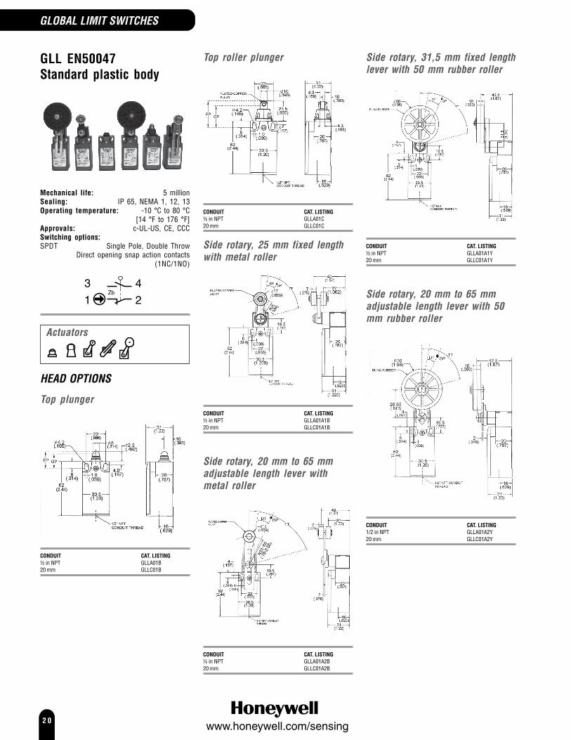
GLL EN50047Standard plastic body
Mechanical life: 5 millionSealing: IP 65, NEMA 1, 12, 13Operating temperature: -10 °C to 80 °C
[14 °F to 176 °F]Approvals: c-UL-US, CE, CCCSwitching options:SPDT Single Pole, Double Throw
Direct opening snap action contacts(1NC/1NO)
HEAD OPTIONS
Top plunger
CONDUIT CAT. LISTING½ in NPT GLLA01B20 mm GLLC01B
Top roller plunger
CONDUIT CAT. LISTING½ in NPT GLLA01C20 mm GLLC01C
Side rotary, 25 mm fixed lengthwith metal roller
CONDUIT CAT. LISTING½ in NPT GLLA01A1B20 mm GLLC01A1B
Side rotary, 20 mm to 65 mmadjustable length lever withmetal roller
CONDUIT CAT. LISTING½ in NPT GLLA01A2B20 mm GLLC01A2B
Side rotary, 31,5 mm fixed lengthlever with 50 mm rubber roller
CONDUIT CAT. LISTING½ in NPT GLLA01A1Y20 mm GLLC01A1Y
Side rotary, 20 mm to 65 mmadjustable length lever with 50mm rubber roller
CONDUIT CAT. LISTING1/2 in NPT GLLA01A2Y20 mm GLLC01A2Y
GLOBAL LIMIT SWITCHES
Actuators

2 1www.honeywell.com/sensing
OPTIONS
Top pin plunger
25,4(OP)
CONTACT CAT. LISTINGSilver SL1-HGold clad cross point SL1-HK
Top roller plunger, parallel
31,4(OP)
CONTACT CAT. LISTINGSilver SL1-AGold clad cross point SL1-AK
SL1 SeriesCompact LimitSwitches
The SL1 Series compact limit switches are sealed, sensitive and have a long life. The compact size makes themsuitable for the total miniaturization of machinery or equipment.
Mechanical life: 10 millionSealing: IP 67, NEMA 3, 4, 13Operating temperature: -10 °C to 70 °C [14 °F to 160 °F]Approvals: UL, CSA, CETermination: Cable glandOperating force max. (OF): 11,76 N [2.64 lb]Pretravel max. (PT): 1,5 mm [0.060 in]Overtravel min. (OT): 3,0 mm [0.118 in]Differential travel max. (DT): 0,10 mm [0.004 in]Electrical rating/contact: SL1-* 5A - 125, 250 Vac Silver
SL1-* K 0.1 A - 125 Vac; 0.1 A - 30 Vdc Gold clad cross pointSwitching options:SPDT Single Pole, Double Throw,
Snap action contacts (1NC/1NO)
Top roller plunger, parallel, boot seal
11 D X 4W ROLLER
PT
CONTACT CAT. LISTINGSilver SL1-BGold clad cross point SL1-BK
Top roller plunger, long, parallel
41,4(OP)
CONTACT CAT. LISTINGSilver SL1-EGold clad cross point SL1-EK
COMPACT LIMIT SWITCHES
Actuators

2 2www.honeywell.com/sensing
COMPACT LIMIT SWITCHES
Top roller plunger, perpendicular
31,4(OP)
CONTACT CAT. LISTINGSilver SL1-DGold clad cross point SL1-DK
Top roller plunger, long, perpendicular
41,4(OP)
CONTACT CAT. LISTINGSilver SL1-KGold clad cross point SL1-KK
Top roller lever
Operating force max. (OF): 3,92 N [0.88 lb]Pretravel max. (PT): 2,0 mm [0.079 in]Overtravel min. (OT): 4,0 mm [0.158 in]Differential travel max. (DT): 0,3 mm [0.012 in]
CONTACT CAT. LISTINGSilver SL1-PGold clad cross point SL1-PK

2 3www.honeywell.com/sensing
14CE/914CE SeriesMiniature EnclosedSwitches
The 14CE/914CE Series offers a miniature, rugged, compact, pre-wired switch which has gainedwide market acceptance and performed successfully in a wide range of potential applications. Theentire range of 14CE and 914CE switches has been approved to meet the requirements of the LowVoltage directive and is therefore CE marked.CE switches have different degrees of protection from IP66 to IP68 for the fully booted head styles.The cable entry is fully potted using a special compound to ensure that ingress is virtuallyimpossible.Mechanical life: 10 millionSealing: IP66, IP67, IP68
NEMA 1, 2, 3, 3R, 4, 6, 6P, 12 (boot seal), 13Operating temperature: 14CE 0 °C to 70 °C [32 °F to 158 °F]
914CE 0 °C to 105 °C [32 °F to 221 °F]Approvals: 14CE CE
914CE CSA, UL, CE AC14 D300 DC13 R300
Operating force (OF): 11,8 N [2,65 lb] max.Pretravel (PT): 1,8 mm [0.71 in] max.Overtravel (OT): 3,0 mm [0.118 in] min.Differential travel (DT): 0,1mm [0.004 in] max.Contact/Rating: (9)14CE* -* Silver A
(9)14CE* -*G Gold B(9)14CE* -Q, -AQ, -AQ1 Silver C
Connection: Harmonised CENELEC 4 x 0,75 mm2 cable (14CE)SJTO 4 x 0,75 mm2 (18 AWG) cable (914CE)Connector (dc), 4 pin male, M12 thread (-Q)
Connector (ac), 4 pin male, ½ in x 20 thread (-Q1)Switching options: SPDT Single Pole, Double Throw
Snap action contacts (1NC/1NO)
914CE 14CE
GREEN/YELLOW
BLUE1
BROWN2
3BLACK
S.P.D.T
Electrical ratings: AmpsMake Break
A 240 Vac, ind. 1.2 0.2240 Vac, res. 5 528 Vdc, res. 3 328 Vdc, ind. 3 3
UL/CSA: 5 A, 1/10 Hp, 125 or 250 Vac
B 1 A res., 0.5 A ind., 30 VdcUL: 1 A, 125 Vac
C UL/CSA: 3 A, 125 or 250 Vac
,,
,
Operatingpoint (OP)
Free position(FP)
1,8 max PT3 min OT
Side exit cable(Option 'A')
14CE 7,4 (0.29)914CE 8,65 (0.34)
Ø
Actuators
COMPACT LIMIT SWITCHES

2 4www.honeywell.com/sensing
COMPACT LIMIT SWITCHES
Plunger actuated switches
OPTIONS
Top pin plungerØ 10,0(0.39) OP
15,7(0.62)
NORTH AMERICA/GLOBAL CAT. LISTING3 ft cable, bottom exit 914CE1-33 ft cable, side exit 914CE1-3A3 ft cable, bottom exit, gold contacts 914CE1-3G6 ft cable, bottom exit 914CE1-66 ft cable, bottom exit, gold contacts 914CE1-6G9 ft cable, bottom exit 914CE1-9Connector (dc), bottom exit 914CE1-QConnector (ac), bottom exit 914CE1-Q1
EUROPE CAT. LISTING1 metre cable, bottom exit 14CE1-11 metre cable, side exit 14CE1-1A1 metre cable, bottom exit, gold contacts 14CE1-1G2 metre cable, bottom exit 14CE1-23 metre cable, bottom exit 14CE1-33 metre cable, side exit 14CE1-3A3 metre cable, bottom exit, gold contacts 14CE1-3GConnector (dc), side exit 14CE1-AQConnector (dc), bottom exit 14CE1-Q
Top pin plunger, boot seal
Ø 7,0(0.28)
OP24,6
(0.98)
Operating force (OF): 22,5 N [5.06 lb]
NORTH AMERICA/GLOBAL CAT. LISTING3 ft cable, bottom exit 914CE18-33 ft cable, side exit 914CE18-3A6 ft cable, bottom exit 914CE18-69 ft cable, bottom exit 914CE18-99 ft cable, side exit 914CE18-9AConnector (ac), side exit 914CE18-AQ1Connector (dc), bottom exit 914CE18-QConnector (ac), bottom exit 914CE18-Q1
EUROPE CAT. LISTING1 metre cable, bottom exit 14CE18-13 metre cable, bottom exit 14CE18-3Connector (dc), bottom exit 14CE18-Q
Top pin plunger, panel mounted
M10x1 ThreadOP29,2
(1.15)
NORTH AMERICA/GLOBAL CAT. LISTINGConnector (dc), bottom exit 914CE27-Q
Ball bearing plunger
OP24,4
(0.96)
NORTH AMERICA/GLOBAL CAT. LISTING3 ft cable, bottom exit 914CE66-36 ft cable, bottom exit 914CE66-6
EUROPE/ CAT. LISTING1 metre cable, bottom exit 14CE66-12 metre cable, bottom exit 14CE66-2
Adjustable plunger
OP
NORTH AMERICA/GLOBAL CAT. LISTING3 ft cable, bottom exit 914CE19-39 ft cable, bottom exit 914CE19-9
Manually operated
OP27,4
(1.08)
Operating force (OF): 9,0 N [2.02 lb]
NORTH AMERICA/GLOBAL CAT. LISTING6 ft cable, bottom exit 914CE22-6
Top roller plunger, parallel
Ø 12,4(0.49) OP
28,4(1.12)
NORTH AMERICA/GLOBAL CAT. LISTING3 ft cable, bottom exit 914CE2-33 ft cable, side exit 914CE2-3A3 ft cable, bottom exit, gold contacts 914CE2-3G6 ft cable, bottom exit 914CE2-66 ft cable, side exit 914CE2-6A9 ft cable, bottom exit 914CE2-9Connector (dc), side exit 914CE2-AQConnector (dc), bottom exit 914CE2-QConnector (ac), bottom exit 914CE2-Q1
EUROPE CAT. LISTING1 metre cable, bottom exit 14CE2-11 metre cable, side exit 14CE2-1A1 metre cable, bottom exit, gold contacts 14CE2-1G2 metre cable, bottom exit 14CE2-22 metre cable, side exit 14CE2-2A3 metre cable, bottom exit 14CE2-33 metre cable, side exit 14CE2-3A3 metre cable, bottom exit, gold contacts 14CE2-3GConnector (dc), side exit 14CE2-AQConnector (dc), bottom exit 14CE2-Q
Top roller plunger, parallel, bootseal
Ø 12,4(0.49)
OP34,4
(1.35)
Operating force (OF): 17,5 N [3.82 lb]
NORTH AMERICA/GLOBAL CAT. LISTING3 ft cable, bottom exit 914CE31-36 ft cable, bottom exit 914CE31-6
EUROPE CAT. LISTING1 metre cable, bottom exit 14CE31-13 metre cable, bottom exit 14CE31-3
Top roller plunger, parallel,panel mounted
OP42,5
(1.67)
NORTH AMERICA/GLOBAL CAT. LISTING3 ft cable, bottom exit 914CE28-36 ft cable, bottom exit 914CE28-6Connector (dc), bottom exit 914CE28-Q

2 5www.honeywell.com/sensing
14CE/914CE SeriesPlunger actuated switches(continued)
Top roller plunger, perpendicular
Ø 12,4(0.49)
OP28,5
(1.12)
5,1(0.20)
NORTH AMERICA/GLOBAL CAT. LISTING3 ft cable, bottom exit 914CE3-36 ft cable, bottom exit 914CE3-66 ft cable, side exit 914CE3-6A9 ft cable, bottom exit 914CE3-9Connector (dc), bottom exit 914CE3-QConnector (ac), bottom exit 914CE3-Q1
EUROPE CAT. LISTING1 metre cable, bottom exit 14CE3-12 metre cable, bottom exit 14CE3-23 metre cable, bottom exit 14CE3-3
Top roller plunger,perpendicular, boot seal
OP34,4
(1.35)
Operating force (OF): 17,5 N [3.82 lb]
NORTH AMERICA/GLOBAL CAT. LISTING3 ft cable, bottom exit 914CE55-33 ft cable, side exit 914CE55-3A
Top roller plunger,perpendicular, panel mounted
OP42,5
(1.67)
NORTH AMERICA/GLOBAL CAT. LISTING3 ft cable, bottom exit 914CE29-36 ft cable, bottom exit 914CE29-6
Side rotary and wobbleactuated switches
OPTIONS
Rotary motion(actuating lever not included - use anyLSZ51*, LSZ52*, LSZ54*, LSZ55* or LSZ61*Series shown on pages 71-73)
Operating torque: 0,3 Nm [2.66 in lb]Pretravel (PT): 30° max.Overtravel (OT) mm: 40° min.Differential travel: 3°
NORTH AMERICA/GLOBAL CAT. LISTING3 ft cable, bottom exit 914CE16-33 ft cable, side exit 914CE16-3A6 ft cable, bottom exit 914CE16-69 ft cable, bottom exit 914CE16-9Connector (dc), bottom exit 914CE16-Q
EUROPE CAT. LISTING1 metre cable, bottom exit 14CE16-12 metre cable, bottom exit 14CE16-23 metre cable, bottom exit 14CE16-3
Wobble Spring wire
Operating Force (OF): 0,55 N [0.12 lb]
NORTH AMERICA/GLOBAL CAT. LISTING3 ft cable, bottom exit 914CE20-36 ft cable, bottom exit 914CE20-69 ft cable, bottom exit 914CE20-9Connector (dc), bottom exit 914CE20-Q
EUROPE CAT. LISTING1 metre cable, bottom exit 14CE20-13 metre cable, bottom exit 14CE20-3
COMPACT LIMIT SWITCHES

2 6www.honeywell.com/sensing
COMPACT LIMIT SWITCHES
24CE/924CE SeriesMiniature SafetyElectromechanicalSwitches
Free position
Note: connector versions also available
2 Holes 5,1 diaCounter Bored 10,2 dia x 6 deep(both sides - option 'A' only)
Side exit cable(Option 'A')
max.40 / 1.58
max.16 / 0.63
25 / 0.98
max.49 / 1.93
8 / 0.32
1NC: 8,4 /.33
1NC/1NO: 9,5 /.374
For position sensing and switching applications requiring direct acting, positive opening contactsthe 24CE and 924CE ranges are ideal. They have been tested and approved to meet the requirementsof the Low Voltage directive and positive opening safety contacts per IEC/EN 60947-5-1-3. Thedevices are CE marked. The red colour clearly differentiates this safety component in the application.The 924CE range also has UL and CSA approval.It is possible for the end user to enhance the safety level of these switches from Category 1 on theirown to Categories 2, 3 or 4 when the switches are used in conjunction with our wide range of FF-SRsafety relays to form a safety system.Potential applications for these switches could use the roller plunger 24CE2- or 24CE3- style inconjunction with cams on doors with hinges; or our fixed side rotary 24CE16- style for detection ofsliding doors. Also available are a range of panel mounting or top mounting versions to ensure thatsmall space or difficult mounting can be simply achieved.Several contact arrangements are available.Mechanical life: 10 millionSealing: standard type: IP66; with boot seal type: IP67Operating temperature: 24CE 0 °C to 70 °C [32 °F to 158 °F]
Low temperature: -40 °C [-40 °F]924CE 0 °C to 105 °C [32 °F to 221 °F]
Approvals: 24CE CEAC15 B300DC13 R300
924CE CSA, CEper UL file #E41859, 10 A 250 Vac; 1/3 Hp 125-250 Vac
AC15 B300 DC13 R300
Connection: Harmonised CENELEC 3 or 5 x 0,75 mm2 cable (24CE)SJTO 3 or 5 x 18 AWG cable (924CE)
Contacts: SilverSwitching options:
924CE 24CESlow action contacts (1NC)
black redgreen
brownbluegreen/yellow
Slow action contacts (1NC/1NO), Break Before Make (BBM)
Zbwhite
redblack
white
greenZb
black
brownblue
black
green/yellow
Slow action contacts (1NC/1NO), Make Before Break (MBB)
white
greenred
white
black
Zb
brown
black
green/yellow
black
blue
Zb
Electrical ratings: IEC 60947-5-1/EN 60947-5-1
Designation & UtilizationRated operational current le (A) VA
. . . . . Category
at rated operational voltage Ue rating120 V 240 V 380 V 480 V 500 V 600 V Make Break
AC15 B300 3 1.5 - - - - 3600 360125 V 250 V
DC13 R300 0,22 0,1 28 28
Actuators

2 7www.honeywell.com/sensing
24CE/924CE Series
OPTIONS
Side rotary
PTPT
OTOT DTDT
North America/GlobalCABLE LENGTH CONTACT CAT. LISTING3 ft 1NC, BBM 924CE16-S39 ft 1NC, BBM 924CE16-S93 ft 1NC, MBB 924CE16-T33 ft 1NC 924CE16-Y39 ft 1NC 924CE16-Y9
EuropeCABLE LENGTH CONTACT CAT. LISTING1 m 1NC/1NO, BBM 24CE16-S11 m 1NC 24CE16-Y16 m 1NC 24CE16-Y6
Top pin plunger
17,5 max.
ø10
North America/GlobalCABLE LENGTH CONTACT OPTION CAT. LISTING3 ft 1NC, BBM 924CE1-S36 ft 1NC, BBM 924CE1-S69 ft 1NC, BBM 924CE1-S925 ft 1NC, MBB side exit 924CE1-T25A3 ft 1NC, MBB 924CE1-T33 ft 1NC, MBB side exit 924CE1-T3A6 ft 1NC, MBB side exit 924CE1-T6A9 ft 1NC, MBB 924CE1-T99 ft 1NC, MBB side exit 924CE1-T9A3 ft 1NC 924CE1-Y39 ft 1NC 924CE1-Y9
EuropeCABLE LENGTH CONTACT OPTION CAT. LISTING12 m 1NC/1NO, BBM low temperature 24CE1-S12B2 m 1NC/1NO, BBM 24CE1-S22 m 1NC/1NO, BBM side exit 24CE1-S2A2 m 1NC/1NO, BBM low temperature 24CE1-S2B3 m 1NC/1NO, BBM 24CE1-S36 m 1NC/1NO, BBM 24CE1-S61 m 1NC side exit 24CE1-Y1A2 m 1NC 24CE1-Y23 m 1NC 24CE1-Y3
Top pin plunger, boot sealed
24,3 max.
ø7,1
North America/GlobalCABLE LENGTH CONTACT CAT. LISTING6 ft 1NC/1NO, BBM 924CE18-S6
Adjustable plunger
OP
North America/GlobalCABLE LENGTH CONTACT OPTION CAT. LISTING3 ft 1NC/1NO, BBM low temperature 924CE19-S3L1
Top roller plunger, parallel
30,3 max.
ø12,4
North America/GlobalCABLE LENGTH CONTACT OPTION CAT. LISTING15 ft 1NC, BBM 924CE2-S1521 ft 1NC, BBM 924CE2-S213 ft 1NC, BBM 924CE2-S36 ft 1NC, BBM 924CE2-S66 ft 1NC, BBM side exit 924CE2-S6A9 ft 1NC, BBM 924CE2-S925 ft 1NC, MBB 924CE2-T2525 ft 1NC, MBB side exit 924CE2-T25A3 ft 1NC, MBB 924CE2-T36 ft 1NC, MBB 924CE2-T69 ft 1NC, MBB 924CE2-T93 ft 1NC 924CE2-Y39 ft 1NC 924CE2-Y9
EuropeCABLE LENGTH CONTACT OPTION CAT. LISTING1 m 1NC/1NO, BBM 24CE2-S12 m 1NC/1NO, BBM 24CE2-S22 m 1NC/1NO, BBM side exit 24CE2-S2A2 m 1NC/1NO, BBM low temperature 24CE2-S2B3 m 1NC/1NO, BBM 24CE2-S36 m 1NC/1NO, BBM 24CE2-S62 m 1NC/1NO, MBB 24CE2-T21 m 1NC 24CE2-Y12 m 1NC 24CE2-Y22 m 1NC side exit 24CE2-Y2A4 m 1NC 24CE2-Y46 m 1NC side exit 24CE2-Y6A
COMPACT LIMIT SWITCHES

2 8www.honeywell.com/sensing
Top roller plunger, parallel,boot sealed
36,1 max.
ø12,4
North America/GlobalCABLE LENGTH CONTACT OPTION CAT. LISTING6 ft 1NC, BBM 924CE31-S620 ft 1NC 924CE31-Y203 ft 1NC low temperature 924CE31-Y3L1
EuropeCABLE LENGTH CONTACT OPTION CAT. LISTING1 m 1NC/1NO, BBM 24CE31-S12 m 1NC/1NO, BBM 24CE31-S22 m 1NC/1NO, BBM low temperature 24CE31-S2B5 m 1NC/1NO, BBM 24CE31-S51 m 1NC 24CE31-Y12 m 1NC 24CE31-Y23 m 1NC 24CE31-Y3
Top roller plunger, parallel,panel mounted
27,7(1.75)
North America/GlobalCABLE LENGTH CONTACT CAT. LISTING15 ft 1NC, BBM 924CE28-S15
EuropeCABLE LENGTH CONTACT CAT. LISTING2 m 1NC/1NO, BBM 24CE28-S2
COMPACT LIMIT SWITCHES
Top roller plunger, perpendicular
30,3 max.
ø12,4
North America/GlobalCABLE LENGTH CONTACT CAT. LISTING3 ft 1NC, BBM 924CE3-S36 ft 1NC, BBM 924CE3-S69 ft 1NC, BBM 924CE3-S99 ft 1NC, MBB 924CE3-T9
EuropeCABLE LENGTH CONTACT CAT. LISTING2 m 1NC/1NO, BBM 24CE3-S21 m 1NC 24CE3-Y12 m 1NC 24CE3-Y2
Top roller plunger,perpendicular, boot sealed
36,1 max.
ø12,4
EuropeCABLE LENGTH CONTACT CAT. LISTING1 m 1NC/1NO, BBM 24CE55-S12 m 1NC/1NO, BBM 24CE55-S21 m 1NC 24CE55-Y1

2 9www.honeywell.com/sensing
LS SeriesCompact LimitSwitches
LS Series compact limit switches are carefully designed for enhanced repeatability under the most stringentconditions. Compact size and field adjustable features greatly extend the flexibility of these switches. Heads maybe positioned at 90° increments. Side rotary models can be adjusted for clockwise and/or counter-clockwiseoperation. Actuators can be set and locked in any position through 360°.The rugged housings and actuator heads are constructed from cast aluminium, capable of withstandingphysical abuse. Protection against oil, water and dust is achieved by O-ring seals on the actuator shaft; a ringseal between head and body; and a seated compression seal between cover and case.The LS fits in many places too small for any other fully adjustable limit switch.Conduit: ½ in - 14 NPT
20 mmSealing: ½ in - 14 NPT conduit NEMA 1, 3, 4, 6, 13
20 mm conduit IP67Operating temperature: Standard -29 °C to 71 °C [-20 °F to 160 °F]
High -29 °C to 121 °C [-20 °F to 250 °F]Approvals: LS-L UL, CSAContacts: Electrical ratings A, B, C, D, E Silver Cadmium Oxide (1)
Electrical ratings F, G Fine SilverSwitching options: SPDT Single Pole, Double Throw
Snap action contacts (1NC/1NO)
4
1
3
2
Electrical ratings: A 10 A, 120, 240 or 480 Vac; 1/3 hp, 120 Vac; ¾ hp, 240 Vac;0.8 A, 115 Vdc**; 0.4 A, 230 Vdc;** 0.1 A, 550 Vdc;**
Pilot Duty, 600 Vac max.
B 10 A, 120, 240 or 480 Vac; ¼ hp, 120 Vac; ½ hp, 240 Vac.Pilot Duty, 600 Vac max.
C 10 A, 120 Vac; 1/3 hp, 120 Vac.
D 10 A, 120, 240, 480 Vac; ¼ hp, 120 Vac; ½ hp, 240 Vac;0.8 A, 115 Vdc**; 0.4 A, 230 Vdc**; 0.1 A, 550 Vdc**;
Pilot Duty, 600 Vac max.
E 10 A, 120, 240 or 480 Vac; 1/3 hp, 120 Vac; ¾ hp, 240 Vac.Pilot Duty, 600 Vac max.
F UL Rating:10 A, 125, 250, or 480 Vac; 1/3 hp, 125 Vac; ¾ hp, 250 Vac;
0.8 A, 125 Vdc**; 0.4 A, 250 Vdc**
G UL Rating:10 A, 125, 250 or 480 Vac; ¼ hp, 125 Vac; ½ hp, 250 Vac;
0.8 A, 125 Vdc**; 0.4 A, 250 Vdc**
** Resistive rating(1) Designed for use with inductive loads such as relays, contactors, motors and solenoids. Honeywell does not
recommend the use of silver cadmium oxide switch contacts in non-arcing loads. Non-arcing loads aregenerally loads less than 12 volts and/or 0.5 amp.
COMPACT LIMIT SWITCHES
Actuators

3 0www.honeywell.com/sensing
COMPACT LIMIT SWITCHES
LS SeriesSide rotary actuated switches
OPTIONS
Fixed length lever
Operating force max. (OF): Standard 13,3 N [3.0 lb]Low 5,0 N [18 oz]
Pretravel max. (PT): Standard 20°Low 5°
Overtravel min. (OT) 30°Differential travel max. (DT): Standard 12°
Low 4°Switching options: SPDTLever: Aluminium, steel roller
CONDUIT ELECTRICAL RATING CAT. LISTINGA 1LS1F 1LS1-L
20 mm A 1LS1-4CLow PT/OF B 1LS131Low PT B 1LS19Low PT 20 mm B 1LS19-4CHigh temperature A 1LS243High temperature 20 mm A 1LS243-4CIndicator light C 1LS501Low OF A 1LS6
Adjustable roller lever
Operating force max. (OF): Standard 13,3 N [3.0 lb]Low 5,0 N [18 oz]
Pretravel max. (PT): Standard 20°Low 5°
Overtravel min. (OT) 30°Differential travel max. (DT): Standard 12°
Low 4°Switching options: SPDTLever: Aluminium, nylon roller
CONDUIT ELECTRICAL RATING CAT. LISTINGA 1LS3F 1LS3-L
20 mm A 1LS3-4CLow PT B 1LS58Low OF/PT/DT B 1LS59
3 1www.honeywell.com/sensing
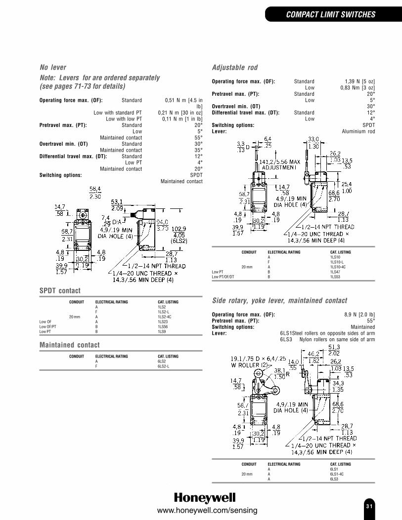
No leverNote: Levers for are ordered separately(see pages 71-73 for details)
Operating force max. (OF): Standard 0,51 N m [4.5 inlb]
Low with standard PT 0,21 N m [30 in oz]Low with low PT 0,11 N m [1 in lb]
Pretravel max. (PT): Standard 20°Low 5°
Maintained contact 55°Overtravel min. (OT) Standard 30°
Maintained contact 35°Differential travel max. (DT): Standard 12°
Low PT 4°Maintained contact 20°
Switching options: SPDTMaintained contact
SPDT contactCONDUIT ELECTRICAL RATING CAT. LISTING
A 1LS2F 1LS2-L
20 mm A 1LS2-4CLow OF A 1LS23Low OF/PT B 1LS56Low PT B 1LS9
Maintained contactCONDUIT ELECTRICAL RATING CAT. LISTING
A 6LS2F 6LS2-L
Adjustable rod
Operating force max. (OF): Standard 1,39 N [5 oz]Low 0,83 Nm [3 oz]
Pretravel max. (PT): Standard 20°Low 5°
Overtravel min. (OT) 30°Differential travel max. (DT): Standard 12°
Low 4°Switching options: SPDTLever: Aluminium rod
CONDUIT ELECTRICAL RATING CAT. LISTINGA 1LS10F 1LS10-L
20 mm A 1LS10-4CLow PT B 1LS47Low PT/OF/DT B 1LS53
Side rotary, yoke lever, maintained contact
Operating force max. (OF): 8,9 N [2.0 lb]Pretravel max. (PT): 55°Switching options: MaintainedLever: 6LS1Steel rollers on opposite sides of arm
6LS3 Nylon rollers on same side of arm
CONDUIT ELECTRICAL RATING CAT. LISTINGA 6LS1
20 mm A 6LS1-4CA 6LS3
COMPACT LIMIT SWITCHES

3 2www.honeywell.com/sensing
COMPACT LIMIT SWITCHES
LS SeriesPlunger actuated switches
OPTIONS
Top pin plunger
Operating force max. (OF): Standard 31,14 N [7 lb]Low 10 N [36 oz]
Pretravel max. (PT): 1,65 mm [0.065 in]Overtravel min. (OT) Standard 6,35 mm [0.25 in]
Low 5,56 mm [0.219 in]Differential travel max. (DT): Standard 0,51 mm [0.020 in]
Low 0,23 mm [0.009 in]Switching options: SPDT
CONDUIT ELECTRICAL RATING CAT. LISTINGA 2LS1F 2LS1-L
20 mm A 2LS1-4CLow OF/OT/DT E 2LS111
Top roller plunger
Operating force max. (OF): 31,14 N [7 lb]Pretravel max. (PT): 1,65 mm [0.065 in]Overtravel min. (OT) 5,56 mm [0.219 in]Differential travel max. (DT): 0,51 mm [0.020 in]Switching options: SPDT
CONDUIT ELECTRICAL RATING CAT. LISTINGA 5LS1F 5LS1-L
20 mm A 5LS1-4C
Side pin plunger
Operating force max. (OF): 40,03 N [9 lb]Pretravel max. (PT): 2,8 mm [0.110 in]Overtravel min. (OT) 6,35 mm [0.25 in]Differential travel max. (DT): 1,02 mm [0.040 in]Switching options: SPDT
CONDUIT ELECTRICAL RATING CAT. LISTINGA 4LS1
20 mm A 4LS1-4C
Side roller plunger
Operating force max. (OF): 40,03 N [9 lb]Pretravel max. (PT): 2,8 mm [0.110 in]Overtravel min. (OT) 5,56 mm [0.219
in]Differential travel max. (DT): 1,02 mm [0.040
in]Switching options: SPDT
CONDUIT ELECTRICAL RATING CAT. LISTINGA 3LS1
20 mm A 3LS1-4C

3 3www.honeywell.com/sensing
Wobble actuated switches
These switches will operate by moving actuator inany direction except direct pull.
Operating force max. (OF): 1,39 N [5 oz]Pretravel max. (PT): 28,6 mm [1,125
in]Switching options: SPDT
OPTIONS
Flexible cable
141,0 ±2,54(5,550 ±0.10)
Ø 4,80 ±0.08(0.189 ±0.003)
CONDUIT ELECTRICAL RATING CAT. LISTINGD 8LS1G 8LS1-L
20 mm D 8LS1-4C
Spring rod
CONDUIT ELECTRICAL RATING CAT. LISTINGD 8LS3
20 mm D 8LS3-4C
Coil spring
Ø 6,17 ±0.08(0.264 ±0.003)
141,0 ±2,54(5,550 ±0.10)
CONDUIT ELECTRICAL RATING CAT. LISTINGD 8LS152
20 mm D 8LS152-4C
Steel wireOperating force max. (OF): 0,28 N [1 oz]Pretravel max. (PT): 63,5 mm [2.5 in]
191,3(7.53)
CONDUIT ELECTRICAL RATING CAT. LISTINGD 8LS125
20 mm D 8LS125-4C
COMPACT LIMIT SWITCHES
3 4www.honeywell.com/sensing
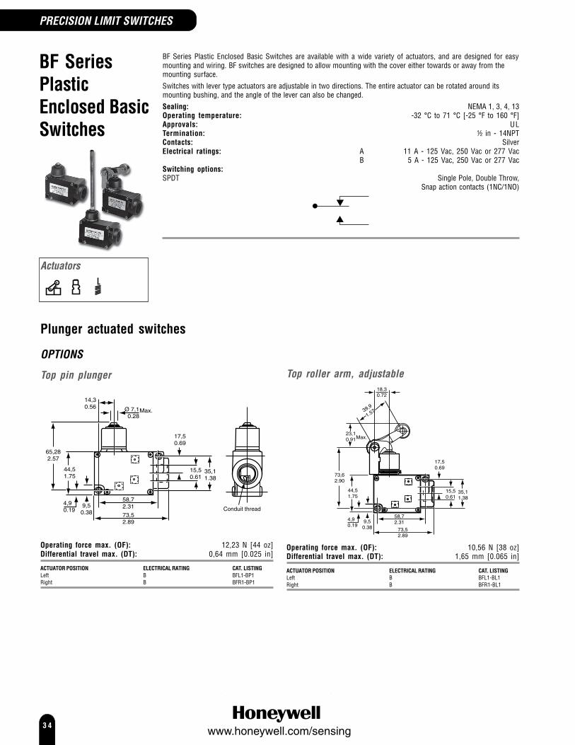
BF SeriesPlasticEnclosed BasicSwitches
PRECISION LIMIT SWITCHES
BF Series Plastic Enclosed Basic Switches are available with a wide variety of actuators, and are designed for easymounting and wiring. BF switches are designed to allow mounting with the cover either towards or away from themounting surface.Switches with lever type actuators are adjustable in two directions. The entire actuator can be rotated around itsmounting bushing, and the angle of the lever can also be changed.Sealing: NEMA 1, 3, 4, 13Operating temperature: -32 °C to 71 °C [-25 °F to 160 °F]Approvals: ULTermination: ½ in - 14NPTContacts: SilverElectrical ratings: A 11 A - 125 Vac, 250 Vac or 277 Vac
B 5 A - 125 Vac, 250 Vac or 277 VacSwitching options:SPDT Single Pole, Double Throw,
Snap action contacts (1NC/1NO)
Plunger actuated switches
OPTIONS
Top pin plunger
58,72.31
73,52.89
35,11.38
15,50.61
17,50.69
4,90.19
44,51.75
65,282.57
Ø 7,10.28
Max.
14,30.56
9,50.38
Conduit thread
Operating force max. (OF): 12,23 N [44 oz]Differential travel max. (DT): 0,64 mm [0.025 in]
ACTUATOR POSITION ELECTRICAL RATING CAT. LISTINGLeft B BFL1-BP1Right B BFR1-BP1
Top roller arm, adjustable
58,72.31
73,52.89
35,11.38
15,50.61
17,50.69
4,90.19
44,51.75
73,62.90
9,50.38
39,9
1.57
23,10.91Max.
18,30.72
Operating force max. (OF): 10,56 N [38 oz]Differential travel max. (DT): 1,65 mm [0.065 in]
ACTUATOR POSITION ELECTRICAL RATING CAT. LISTINGLeft B BFL1-BL1Right B BFR1-BL1
Actuators

3 5www.honeywell.com/sensing
PRECISION LIMIT SWITCHES
Plunger actuated switches(continued)
Top roller arm, adjustable, oneway
14,730.58
32,261.27
19,050.75
180˚
58,72.31
73,52.89
35,11.38
Ø 15,50.61
44,51.75
73,62.90
9,50.38
4,90.19
17,50.69
39,61.56
18,30.72
Operating force max. (OF):Left 3,61 N [13 oz]Right 10,56 N [38 oz]
ACTUATOR ELECTRICAL CAT. LISTINGPOSITION RATINGLeft B BFL1-BL3Right B BFR1-BL3
Low force rod
58,72.31
73,52.89
44,51.75
73,62.90
9,50.38
4,90.19
14,730.58
35,11.38
Ø 15,50.61
17,50.69
18,30.72
250˚
Operating force max. (OF):Left 10,56 N [38 oz]Right 3,61 N [13 oz]
ACTUATOR ELECTRICAL CAT. LISTINGPOSITION RATINGLeft B BFL1-BL2Right B BFR1-BL2
Wobble actuated switchesOperating force max. (OF): 1,95 N [7 oz]
OPTIONS
Coil spring
58,72.31
73,52.89
35,11.38
15,50.61
17,50.69
4,90.19
44,51.75
169,96.69
Ø 7,10.28
Max.
14,30.56
9,50.38
ACTUATOR ELECTRICAL CAT. LISTINGPOSITION RATINGLeft A BFL1-AW1Left B BFL1-BW1Right B BFR1-BW1
Plastic
58,72.31
73,52.89
35,11.38
15,50.61
17,50.69
4,90.19
44,51.75
249,259.81
Ø 7,10.28
14,30.56
9,50.38
C
Type -BW3
ACTUATOR ELECTRICAL CAT. LISTINGPOSITION RATINGLeft, A BFL1-AW2179,3 mm [7.06 in] length rodLeft, B BFL1-BW3249,25 mm [9.8 in] length rod
Spring wire
14,70.58
35,11.38
15,50.61
17,50.69
44,51.75
4,90.19
9,50.38
168,86.65
14,30.56
Ø 1,020.05
73,52.89
58,72.31
ACTUATOR ELECTRICAL CAT. LISTINGPOSITION RATINGLeft B BFL1-BW4Right B BFR1-BW4
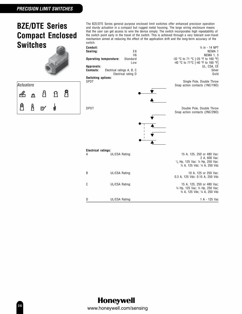
3 6www.honeywell.com/sensing
BZE/DTE SeriesCompact EnclosedSwitches
The BZE/DTE Series general purpose enclosed limit switches offer enhanced precision operationand sturdy actuation in a compact but rugged metal housing. The large wiring enclosure meansthat the user can get access to wire the device simply. The switch incorporates high repeatability ofthe switch point early in the travel of the switch. This is achieved through a very tolerant over-travelmechanism aimed at reducing the effect of the application drift and the long-term accuracy of theswitch.Conduit: ½ in - 14 NPTSealing: E6 NEMA 1
V6 NEMA 1, 3Operating temperature: Standard -32 °C to 71 °C [-25 °F to 160 °F]
Low -40 °C to 71°C [-40 °F to 160 °F]Approvals: UL, CSA, CEContacts: Electrical ratings A, B, C Silver
Electrical rating D GoldSwitching options:SPDT Single Pole, Double Throw
Snap action contacts (1NC/1NO)
DPDT Double Pole, Double ThrowSnap action contacts (2NC/2NO)
Electrical ratings:A UL/CSA Rating: 15 A, 125, 250 or 480 Vac:
2 A, 600 Vac:1/8 Hp, 125 Vac: ¼ Hp, 250 Vac:
½ A, 125 Vdc: ¼ A, 250 Vdc
B UL/CSA Rating: 10 A, 125 or 250 Vac:0.3 A, 125 Vdc: 0.15 A, 250 Vdc
C UL/CSA Rating: 15 A, 125, 250 or 480 Vac;¼ Hp, 125 Vac; ½ Hp, 250 Vac;
½ A, 125 Vdc; ¼ A, 250 Vdc
D UL/CSA Rating: 1 A - 125 Vac
PRECISION LIMIT SWITCHES
Actuators
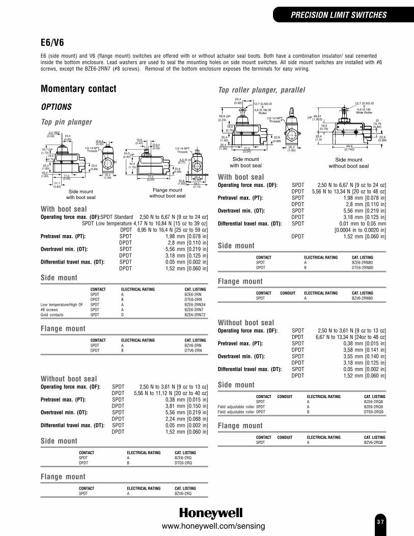
3 7www.honeywell.com/sensing
E6/V6E6 (side mount) and V6 (flange mount) switches are offered with or without actuator seal boots. Both have a combination insulator/ seal cementedinside the bottom enclosure. Lead washers are used to seal the mounting holes on side mount switches. All side mount switches are installed with #6screws, except the BZE6-2RN7 (#8 screws). Removal of the bottom enclosure exposes the terminals for easy wiring.
PRECISION LIMIT SWITCHES
Top roller plunger, parallel23,4
(0.92)
56,6(2,23)
OP
19,0(0.75)
25,4(1.00)
25,4(1.00) 25,4
(1.00)77,2
(3.04)
22,6(0.89)
1/2-14 NPTThreads
12,7 (0.50) ØX
4,6 (0.18) WRoller
Side mountwith boot seal
25,4(1.0)
19,0(0.75)
69,6(2.740)
22,6(0.89)
12,7 (0.50) ØX
4,6 (0.18) Wide Roller
49,61(1.953)OP
Ø15,75(0.62)
Side mountwithout boot seal
With boot sealOperating force max. (OF): SPDT 2,50 N to 6,67 N [9 oz to 24 oz]
DPDT 5,56 N to 13,34 N [20 oz to 48 oz]Pretravel max. (PT): SPDT 1,98 mm [0.078 in]
DPDT 2,8 mm [0.110 in]Overtravel min. (OT): SPDT 5,56 mm [0.219 in]
DPDT 3,18 mm [0.125 in]Differential travel max. (DT): SPDT 0,01 mm to 0,05 mm
[0.0004 in to 0.0020 in]DPDT 1,52 mm [0.060 in]
Side mountCONTACT ELECTRICAL RATING CAT. LISTINGSPDT A BZE6-2RN80DPDT B DTE6-2RN80
Flange mountCONTACT CONDUIT ELECTRICAL RATING CAT. LISTINGSPDT A BZV6-2RN80
Without boot sealOperating force max. (OF): SPDT 2,50 N to 3,61 N [9 oz to 13 oz]
DPDT 6,67 N to 13,34 N [24oz to 48 oz]Pretravel max. (PT): SPDT 0,38 mm [0.015 in]
DPDT 3,58 mm [0.141 in]Overtravel min. (OT): SPDT 3,55 mm [0.140 in]
DPDT 3,18 mm [0.125 in]Differential travel max. (DT): SPDT 0,05 mm [0.002 in]
DPDT 1,52 mm [0.060 in]
Side mountCONTACT CONDUIT ELECTRICAL RATING CAT. LISTINGSPDT A BZE6-2RQ8
Field adjustable roller SPDT A BZE6-2RQ9Field adjustable roller DPDT B DTE6-2RQ9
Flange mountCONTACT CONDUIT ELECTRICAL RATING CAT. LISTINGSPDT A BZV6-2RQ8
Momentary contact
OPTIONS
Top pin plunger2,0
(0.08)REF
23,4(0.92)
43,7(1.72)
OP
19,0(0.75)
25,4(1.00)
25,4(1.00) 25,4
(1.00)
21,1(0.83)
77,2(3.04)
77,2(3.04)
22,6(0.89)
Ø 8,4(0.33)
1/2-14 NPTThreads
1/2-14 NPTThreads
10,6(0.42) Ø 8,4
(0.33)
63,5(2.50)
OP
44,4(1.75)
22,6(0.89)
4,3(0.17)
Ø (2)
41,4(1.63)
25,4(1.00)54,1
(2.13)
Side mountwith boot seal
Flange mountwithout boot seal
With boot sealOperating force max. (OF):SPDT Standard 2,50 N to 6,67 N [9 oz to 24 oz]
SPDT Low temperature 4,17 N to 10,84 N [15 oz to 39 oz]DPDT 6,95 N to 16,4 N [25 oz to 59 oz]
Pretravel max. (PT): SPDT 1,98 mm [0.078 in]DPDT 2,8 mm [0.110 in]
Overtravel min. (OT): SPDT 5,56 mm [0.219 in]DPDT 3,18 mm [0.125 in]
Differential travel max. (DT): SPDT 0.05 mm [0.002 in]DPDT 1,52 mm [0.060 in]
Side mountCONTACT ELECTRICAL RATING CAT. LISTINGSPDT A BZE6-2RNDPDT B DTE6-2RN
Low temperature/High OF SPDT A BZE6-2RN34#8 screws SPDT A BZE6-2RN7Gold contacts SPDT D BZE6-2RN72
Flange mountCONTACT ELECTRICAL RATING CAT. LISTINGSPDT A BZV6-2RNDPDT B DTV6-2RN
Without boot sealOperating force max. (OF): SPDT 2,50 N to 3,61 N [9 oz to 13 oz]
DPDT 5,56 N to 11,12 N [20 oz to 40 oz]Pretravel max. (PT): SPDT 0,38 mm [0.015 in]
DPDT 3,81 mm [0.150 in]Overtravel min. (OT): SPDT 5,56 mm [0.219 in]
DPDT 2,24 mm [0.088 in]Differential travel max. (DT): SPDT 0,05 mm [0.002 in]
DPDT 1,52 mm [0.060 in]
Side mountCONTACT ELECTRICAL RATING CAT. LISTINGSPDT A BZE6-2RQDPDT B DTE6-2RQ
Flange mountCONTACT ELECTRICAL RATING CAT. LISTINGSPDT A BZV6-2RQ

3 8www.honeywell.com/sensing
BZE/DTE SeriesE6/V6 Momentary contact (continued)
Top roller plunger, perpendicular
Flange mountwithout boot seal
56,6(2,23)
OP
19,0(0.75)
25,4(1.00)
25,4(1.00) 77,2
(3.04)
22,6(0.89)
12,7 (0.50) ØX
4,6 (0.18) WRoller
Side mountwith boot seal
With boot sealOperating Force max. (OF): 2,60 N to 6,67 N [9 oz to 24 oz]Pretravel max. (PT): 1,98 mm [0.078 in]Overtravel min. (OT): 5,56 mm [0.219 in]Differential travel max. (DT): 0,01 mm to 0,05 mm
[0.0004 in to 0.0020 in]
Side mountCONTACT ELECTRICAL RATING CAT. LISTINGSPDT A BZE6-2RN81
Without boot sealOperating Force max. (OF): SPDT 2,50 N to 3,61 N [9 oz to 13 oz]
DPDT 6,67 N to 13,34 N [24 oz to 48 oz]Pretravel max. (PT): SPDT 0,38 mm [0.015 in]
DPDT 3,58 mm [0.141 in]Overtravel min. (OT): SPDT 3,55 mm [0.140 in]
DPDT 3,18 mm [0.125 in]Differential travel max. (DT): SPDT 0,05 mm [0.002 in]
DPDT 1,52 mm [0.060 in]
Side mountCONTACT ELECTRICAL RATING CAT. LISTINGSPDT A BZE6-2RQ81DPDT B DTE6-2RQ81
Flange mountCONTACT ELECTRICAL RATING CAT. LISTINGSPDT A BZV6-2RQ81
Roller arm, adjustable
Side mountwithout boot seal
Flange mountwith boot seal
Operating temperature: Standard -32 °C to 71 °C [-25 °F to 160 °F]Low -40 °C to 71 °C [-40 °F to 160 °F]
Roller: Steel
With boot sealOperating Force max. (OF): 2,78 N to 5,56 N [10 oz to 20 oz]Pretravel max. (PT): 4,78 mm [0.188 in]Overtravel min. (OT): 5,56 mm [0.219 in]Differential travel max. (DT): SPDT 0,15 mm [0.006 in]
DPDT 4,19 mm [0.165 in]
Side mountOperating Force max. (OF): DPDT 13,34 N [48 oz]Pretravel max. (PT): DPDT 7,92 mm [0.312 in]
CONTACT ELECTRICAL RATING CAT. LISTINGSPDT A BZE6-2RN2DPDT B DTE6-2RN2
Low temperature SPDT A BZE6-2RN234
Flange mountOperating Force max. (OF): DPDT 2,78 N to 8,34 N [10 oz to 30 oz]Pretravel max. (PT): DPDT 6,76 mm [0.266 in]
CONTACT ELECTRICAL RATING CAT. LISTINGSPDT A BZV6-2RN2DPDT B DTV6-2RN2
Without boot sealOperating Force max. (OF): 2,78 N to 5,00 N [10 oz to 20 oz]Pretravel max. (PT): 4,78 mm [0.188 in]Overtravel min. (OT): 5,56 mm [0.219 in]Differential travel max. (DT): 0,15 mm [0.006 in]
CONTACT ELECTRICAL RATING CAT. LISTINGSide mount SPDT A BZE6-2RQ2Flange mount SPDT A BZV6-2RQ2
PRECISION LIMIT SWITCHES

3 9www.honeywell.com/sensing
One way roller lever
Side mountwith boot seal
With boot sealOperating Force max. (OF): 2,22 N to 5,56 N [8 oz to 20 oz]Pretravel max. (PT): 5,94 mm [0.234 in]Overtravel min. (OT): 5,56 mm [0.219 in]Differential travel max. (DT): 0,15 mm [0.006 in]
CONTACT ELECTRICAL RATING CAT. LISTINGSide mount SPDT A BZE6-2RN28
Rod leverPretravel max. (PT): 18,24 mm [0.718 in]Overtravel min. (OT): 21,29 mm [0.838 in]Differential travel max. (DT): 5,82 mm [0.229 in]
Flange mountwithout boot seal
Side mountwith boot seal
Ø 15,75(0.62)
25,4(1.00)
77,2(3.04)
69,60(2,74)
22,6(0.89)
19,05(0.75)
250˚
152,4(6.0)
18,29(0.72)
53,19(2.09)
With boot sealOperating force max. (OF): 0,83 N to 1,95 N [3 oz to 7 oz]
CONTACT ELECTRICAL RATING CAT. LISTINGSide mount SPDT A BZE6-2RN62Flange mount SPDT A BZV6-2RN62
Without boot sealOperating force max. (OF): 0,56 N to 1,39 N [2 oz to 5 oz]
CONTACT ELECTRICAL RATING CAT. LISTINGSide mount SPDT A BZE6-2RQ62Flange mount SPDT A BZV6-2RQ62
Manual palm button
Side mountwith boot seal
36,61.44
18,30.72
31,81.25
1/2 - 14 NPSM5 THREADS MIN
78,53.09
44,41.75
77,23.04
22,60.89
4,30.17
Ø (2)
41,41.63
38,11.50
25,41.0054,12.13
With boot sealOperating force max. (OF): 2,78 N to 5,56 N [10 oz to 20 oz]Pretravel max. (PT): 4,78 mm [0.188 in]Overtravel min. (OT): 5,56 mm [0.219 in]Differential travel max. (DT): 0,15 mm [0.006 in]
CONTACT ELECTRICAL RATING CAT. LISTINGFlange mount SPDT A BZV6-2RN4
Wobble, coil springThese switches will operate by moving actuator in any direction except directpull.
Flange mountwith boot seal
With boot sealOperating force max. (OF): 1,95 N [7 oz]Pretravel max. (PT): 15°
CONTACT ELECTRICAL RATING CAT. LISTINGSide mount SPDT A BZE6-2RN18Flange mount SPDT A BZV6-2RN18
PRECISION LIMIT SWITCHES

4 0www.honeywell.com/sensing
BZE/DTE SeriesE6/V6 Maintained contact (reset) switchesThe switches shown below provide maintained contact after theoperating force on either top or bottom plunger is released.Note: The top plungers on these switches provide enhanced accuracyand uniform operation than the “reset” plungers and should be usedwhen closely held operating characteristics are required.Switching:SPDT Single Pole, Double Throw
(1NC/1NO) Maintained
OPTIONS
Top pin plunger
Side mountwith boot seal
Flange mountwithout boot seal
Side mountOperating force max. (OF): With boot seal 1,67 N to 5,56 N [6 oz to 20 oz]
Without boot seal 1,67 N to 2,64 N [6 oz to 9.5 oz]Pretravel max. (PT): With boot seal 1,98 mm [0.078 in]
Without boot seal 0.30 mm [0.012 in]Overtravel min. (OT): 4,75 mm [0.187 in]
CONTACT ELECTRICAL RATING CAT. LISTINGWith boot seal SPDT Maintained C BZE6-RNX1Without boot seal SPDT Maintained C BZE6-RQX2
Top roller plunger
Side mountwithout boot seal
56,69(2.232)
53,19(2.094)Reset
FP
19,0(0.75)
25,4(1.00)
22,6(0.89)
Ø 15,75(0.62)
Ø 25,4(1.0)
40,08(1.58)
14,22(0.56)
23,19(0.913)
69,59(2.74)
Ø 12,7 (0.50) x 4,6 (0.18) Wide roller
Side mountwith boot seal
Side mountOperating force max. (OF): With boot seal 3,34 N to 15,57 N [12 oz to 56 oz]
Without boot seal 1,67 N to 2,64 N [6 oz to 9.5 oz]Pretravel max. (PT): With boot seal 1,98 mm [0.078 in]
Without boot seal 0,30 mm [0.012 in]Overtravel min. (OT): With boot seal 4,75 mm [0.187 in]
Without boot seal 3,55 mm [0.140 in]
CONTACT CONDUIT ELECTRICAL RATING CAT. LISTINGWith boot seal SPDT C BZE6-RN80X2Without boot seal SPDT C BZE6-RQ8X2
Roller arm, adjustable
Flange mountwith boot seal
Side mountwithout boot seal
Side mountOperating Force max. (OF): With boot seal 4,45 N [16 oz]
Without boot seal 3,34 N [12 oz]Pretravel max. (PT): 4,78 mm [0.188 in]Overtravel min. (OT): 5,56 mm [0.219 in]
CONTACT CONDUIT ELECTRICAL RATING CAT. LISTINGWith boot seal Maintained C BZE6-RN2X1Without boot seal Maintained C BZE6-RQ2X2
PRECISION LIMIT SWITCHES

4 1www.honeywell.com/sensing
E7 Metal standard enclosed switchMechanical life: 10 millionSealing: Without boot seal IP50 Standard
With boot seal IP65 SealedOperating temperature: -30 °C to 70 °C [-22 °F to 158 °F]Approvals: IEC 60947-5-1
EN 60947-5-1Switching options:SPDT Single Pole, Double Throw
Snap action contacts (1NC/1NO)
DPDT Double Pole, Double ThrowSnap action contacts (2NC/2NO)
OPTIONS
Top pin plungerWith boot seal
38,58(1.519)
1,93(0.076)
Pretravel
13,97(0.55)
25,4(1.00)
5,84(0.23)
4,06(0.16)
12,7(0.50)
Ø 14,73(0.58)
OP
Ø 8,38(0.33)
76,40(3,01)
CONTACT CONDUIT ELECTRICAL RATING CAT. LISTINGSPDT PG 13.5 BZE7-2RN-PGSPDT 20 mm BZE7-2RN-CDPDT PG 13.5 DTE7-2RN-PG
Without boot sealCONTACT CONDUIT ELECTRICAL RATING CAT. LISTINGSPDT PG 13.5 BZE7-2RQ-PG
Top roller plunger, parallel, without boot seal
44,5(1.75)
3,8(0.15)
Pretravel
13,97(0.55)
25,4(1.00)
5,84(0.23)
4,06(0.16)
12,7(0.50)
Ø 14,73(0.58)
OP
Ø 12,7 x 4,5 wide roller(Ø 0.50 x 0.18)
76,40(3,01)
CONTACT CONDUIT ELECTRICAL RATING CAT. LISTINGSPDT PG 13.5 BZE7-2RQ8-PG
Top roller plunger, perpendicular, without boot seal
44,53(1.75)
0,38(0.015)
Pretravel
13,97(0.55)
25,4(1.00)
5,84(0.23)
4,06(0.16)
12,7(0.50)
Ø 14,73(0.58)
OP
Ø 12,7 x 4,57 (0.50 x 0.18)
76,40(3,01)
Wide roller
CONTACT CONDUIT ELECTRICAL RATING CAT. LISTINGSPDT PG 13.5 BZE7-2RQ81-PG
Top roller lever, boot seal
48,11(1.894)
13,97(0.55)
25,4(1.00)
5,84(0.23)
4,06(0.16)
12,7(0.50)
Ø 14,73(0.58)
Ø 19,05 x 7,92 wide roller(Ø 0.75 x 0.312)
76,40(3,01)
225˚
18,29(0.72)
39,88(1.57)
24,38(0.91)
CONTACT CONDUIT ELECTRICAL RATING CAT. LISTINGSPDT PG 13.5 BZE7-2RN2-PGSPDT 20 mm BZE7-2RN2-C
Wobble, coil spring, boot seal
151,13(5.95)
13,97(0.55)
25,4(1.00)
5,84(0.23)
4,06(0.16)
76,40(3,01)
12,7(0.50)
Ø 14,73(0.58)
CONTACT CONDUIT ELECTRICAL RATING CAT. LISTINGSPDT PG 13.5 BZE7-2RN18-PG
PRECISION LIMIT SWITCHES
Actuators
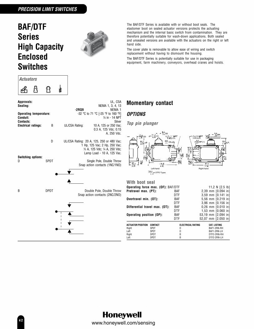
4 2www.honeywell.com/sensing
PRECISION LIMIT SWITCHES
BAF/DTFSeriesHigh CapacityEnclosedSwitches
The BAF/DTF Series is available with or without boot seals. Theelastomer boot on sealed actuator versions protects the actuatingmechanism and the internal basic switch from contamination. They aretherefore potentially suitable for wash-down applications. Both sealedand unsealed versions are available with the actuators on the right or lefthand side.The cover plate is removable to allow ease of wiring and switchreplacement without having to dismount the housing.The BAF/DTF Series is potentially suitable for use in packagingequipment, farm machinery, conveyors, overhead cranes and hoists.
Approvals: UL, CSASealing: NEMA 1, 3, 4, 13
-2RQ9 NEMA 1Operating temperature: -32 °C to 71 °C [-25 °F to 160 °F]Conduit: ½ in - 14 NPTContacts: SilverElectrical ratings: B UL/CSA Rating: 10 A, 125 or 250 Vac;
0.3 A, 125 Vdc; 0.15A, 250 Vdc.
D UL/CSA Rating: 20 A, 125, 250 or 480 Vac;1 Hp, 125 Vac; 2 Hp, 250 Vac;
½ A, 125 Vdc; ¼ A, 250 Vdc;Lamp Load - 10 A, 125 Vac.
Switching options:D SPDT Single Pole, Double Throw
Snap action contacts (1NC/1NO)
B DPDT Double Pole, Double ThrowSnap action contacts (2NC/2NO)
Momentary contact
OPTIONS
Top pin plunger
Left-hand Right-hand
*28,2 on DTF2 Types1.11
With boot sealOperating force max. (OF): BAF/DTF 11,2 N [2.5 lb]Pretravel max. (PT): BAF 2,39 mm [0.094 in]
DTF 3,59 mm [0.141 in]Overtravel min. (OT): BAF 5,56 mm [0.219 in]
DTF 3,96 mm [0.156 in]Differential travel max. (DT): BAF 0,26 mm [0.010 in]
DTF 1,53 mm [0.060 in]Operating position (OP): BAF 53,19 mm [2.094 in]
DTF 52,07 mm [2.050 in]
ACTUATOR POSITION CONTACT ELECTRICAL RATING CAT. LISTINGRight SPDT D BAF1-2RN-RHLeft SPDT D BAF1-2RN-LHRight DPDT B DTF2-2RN-RHLeft DPDT B DTF2-2RN-LH
Actuators
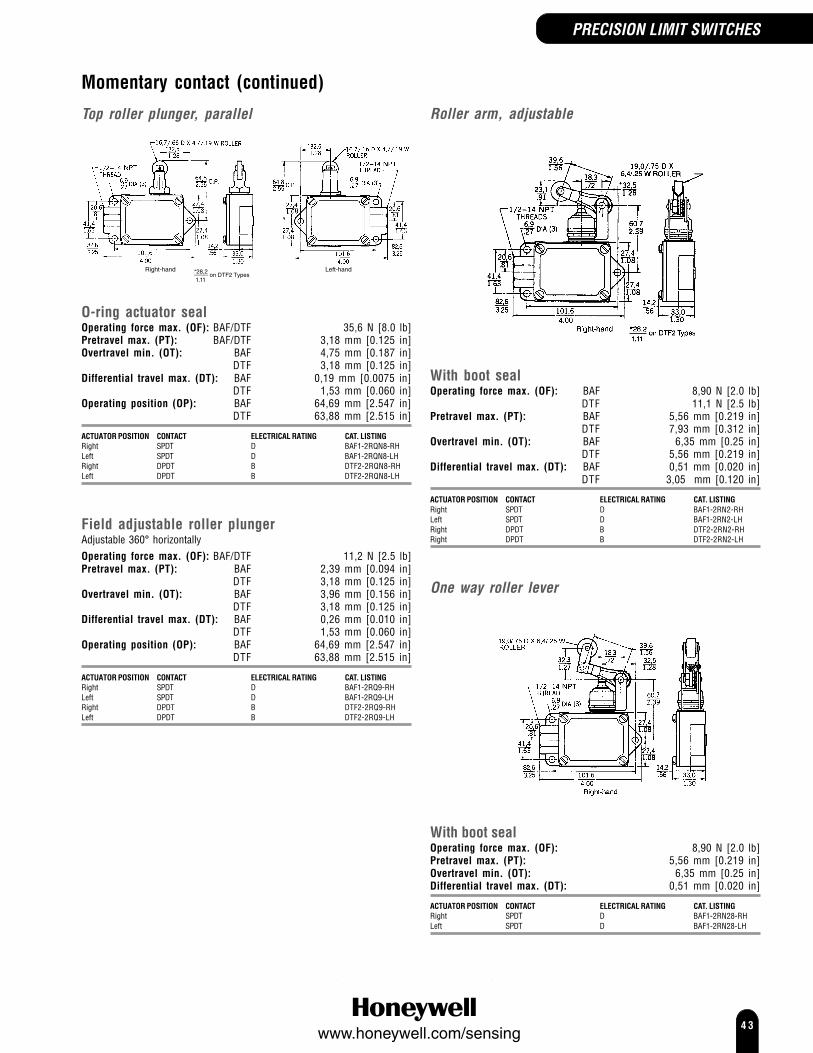
4 3www.honeywell.com/sensing
PRECISION LIMIT SWITCHES
Momentary contact (continued)
Top roller plunger, parallel
Right-hand Left-hand*28,2 on DTF2 Types1.11
O-ring actuator sealOperating force max. (OF): BAF/DTF 35,6 N [8.0 lb]Pretravel max. (PT): BAF/DTF 3,18 mm [0.125 in]Overtravel min. (OT): BAF 4,75 mm [0.187 in]
DTF 3,18 mm [0.125 in]Differential travel max. (DT): BAF 0,19 mm [0.0075 in]
DTF 1,53 mm [0.060 in]Operating position (OP): BAF 64,69 mm [2.547 in]
DTF 63,88 mm [2.515 in]
ACTUATOR POSITION CONTACT ELECTRICAL RATING CAT. LISTINGRight SPDT D BAF1-2RQN8-RHLeft SPDT D BAF1-2RQN8-LHRight DPDT B DTF2-2RQN8-RHLeft DPDT B DTF2-2RQN8-LH
Field adjustable roller plungerAdjustable 360° horizontallyOperating force max. (OF): BAF/DTF 11,2 N [2.5 lb]Pretravel max. (PT): BAF 2,39 mm [0.094 in]
DTF 3,18 mm [0.125 in]Overtravel min. (OT): BAF 3,96 mm [0.156 in]
DTF 3,18 mm [0.125 in]Differential travel max. (DT): BAF 0,26 mm [0.010 in]
DTF 1,53 mm [0.060 in]Operating position (OP): BAF 64,69 mm [2.547 in]
DTF 63,88 mm [2.515 in]
ACTUATOR POSITION CONTACT ELECTRICAL RATING CAT. LISTINGRight SPDT D BAF1-2RQ9-RHLeft SPDT D BAF1-2RQ9-LHRight DPDT B DTF2-2RQ9-RHLeft DPDT B DTF2-2RQ9-LH
Roller arm, adjustable
With boot sealOperating force max. (OF): BAF 8,90 N [2.0 lb]
DTF 11,1 N [2.5 lb]Pretravel max. (PT): BAF 5,56 mm [0.219 in]
DTF 7,93 mm [0.312 in]Overtravel min. (OT): BAF 6,35 mm [0.25 in]
DTF 5,56 mm [0.219 in]Differential travel max. (DT): BAF 0,51 mm [0.020 in]
DTF 3,05 mm [0.120 in]
ACTUATOR POSITION CONTACT ELECTRICAL RATING CAT. LISTINGRight SPDT D BAF1-2RN2-RHLeft SPDT D BAF1-2RN2-LHRight DPDT B DTF2-2RN2-RHRight DPDT B DTF2-2RN2-LH
One way roller lever
With boot sealOperating force max. (OF): 8,90 N [2.0 lb]Pretravel max. (PT): 5,56 mm [0.219 in]Overtravel min. (OT): 6,35 mm [0.25 in]Differential travel max. (DT): 0,51 mm [0.020 in]
ACTUATOR POSITION CONTACT ELECTRICAL RATING CAT. LISTINGRight SPDT D BAF1-2RN28-RHLeft SPDT D BAF1-2RN28-LH
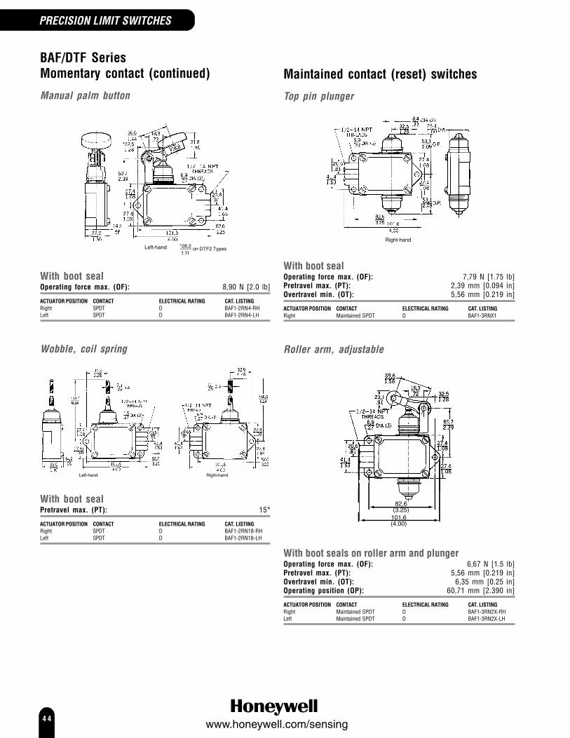
4 4www.honeywell.com/sensing
BAF/DTF SeriesMomentary contact (continued)
Manual palm button
Left-hand *28,2 on DTF2 Types1.11
With boot sealOperating force max. (OF): 8,90 N [2.0 lb]
ACTUATOR POSITION CONTACT ELECTRICAL RATING CAT. LISTINGRight SPDT D BAF1-2RN4-RHLeft SPDT D BAF1-2RN4-LH
Wobble, coil spring
Left-hand Right-hand
With boot sealPretravel max. (PT): 15°
ACTUATOR POSITION CONTACT ELECTRICAL RATING CAT. LISTINGRight SPDT D BAF1-2RN18-RHLeft SPDT D BAF1-2RN18-LH
Maintained contact (reset) switches
Top pin plunger
Right-hand
With boot sealOperating force max. (OF): 7,79 N [1.75 lb]Pretravel max. (PT): 2,39 mm [0.094 in]Overtravel min. (OT): 5,56 mm [0.219 in]
ACTUATOR POSITION CONTACT ELECTRICAL RATING CAT. LISTINGRight Maintained SPDT D BAF1-3RNX1
Roller arm, adjustable
82,6(3.25)
101,6(4.00)
With boot seals on roller arm and plungerOperating force max. (OF): 6,67 N [1.5 lb]Pretravel max. (PT): 5,56 mm [0.219 in]Overtravel min. (OT): 6,35 mm [0.25 in]Operating position (OP): 60,71 mm [2.390 in]
ACTUATOR POSITION CONTACT ELECTRICAL RATING CAT. LISTINGRight Maintained SPDT D BAF1-3RN2X-RHLeft Maintained SPDT D BAF1-3RN2X-LH
PRECISION LIMIT SWITCHES

4 5www.honeywell.com/sensing
Wobble, coil spring
82,6(3.25)
41,4(1.63) 27,4
(1.08)
27,4(1.08)
158,5(6.24)
32,5(1.28)
20,6(0.81)
101,6(4.00)
Ø 7,1(0.28)
Ø 6,9(0.27)
(3)
1/2-14 NPTThreads
With boot seals on wobble stick and plungerPretravel max. (PT): 15°
ACTUATOR POSITION CONTACT ELECTRICAL RATING CAT. LISTINGRight Maintained SPDT D BAF1-3CN18X1
PRECISION LIMIT SWITCHES
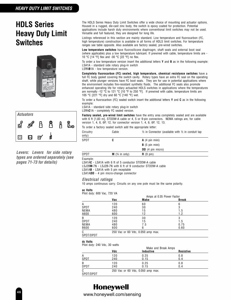
4 6www.honeywell.com/sensing
HEAVY DUTY LIMIT SWITCHES
HDLS SeriesHeavy Duty LimitSwitches
The HDLS Series Heavy Duty Limit Switches offer a wide choice of mounting and actuator options.Housed in a rugged, die-cast zinc body, the switch is epoxy coated for protection. Potentialapplications include harsh duty environments where conventional limit switches may not be used.Versatile and full featured, they are designed for long life.Listings referenced in this section are mainly standard. Low temperature and fluorocarbon (FC,high temperature) construction is available in all forms of HDLS limit switches. For temperatureranges see table opposite. Also available are factory sealed, pre-wired switches.Low temperature switches have fluorosilicone diaphragm, shaft seals and external boot seal(where applicable) plus a low temperature lubricant. If prewired with cable, temperature limits are -10 °C [14 °F] flex and -30 °C [22 °F] no flex.To order a low temperature version insert the additional letters Y and B as in the following example:LSA1A - standard side rotary plug-in switchLSYAB1A - low temperature version.Completely fluorocarbon (FC) sealed, high temperature, chemical resistance switches have afull FC body gasket covering the switch cavity. Rotary types have an extra FC seal on the operatingshaft, while plunger versions have FC boot seals. They are for use in potential applications wherethe environment includes fire-resistant synthetic fluids. The additional FC seals also promoteenhanced operating life for rotary actuacted HDLS switches in applications where the temperaturesare normally -12 °C to 121 °C [10 °F to 250 °F]. If prewired with cable, temperature limits are105 °C [221 °F] dry and 60 °C [140 °F] wet.To order a fluorocarbon (FC) sealed switch insert the additional letters Y and C as in the followingexample:LSA1A - standard side rotary plug-in switchLSYAC1A - completely FC sealed version.Factory sealed, pre-wired limit switches have the entry area completely sealed and are availablewith 6 ft [1,83 m], STOOW-A cable or 4, 5 or 9-pin connectors. NEMA ratings are, for cableversion 1, 4, 6, 6P, 12, for connector version 1, 4, 6, 6P, 12, 13.To order a factory sealed switch add the appropriate letter:Circuitry Cable ½ in Connector (available with ½ in conduit taponly)SPDT C A (4 pin mini)
B (5 pin mini)DD (4 pin micro)
DPDT M (¾ in only) R (9 pin)Example:LSA1AC - LSA1A with 6 ft of 5 conductor STOOW-A cableLSJ2BM-7N - LSJ2B-7N with 6 ft of 9 conductor STOOW-A cableLSA1AB - LSA1A with 5 pin receptableLSA1ADD - 4 pin micro-change connector
Electrical ratings10 amps continuous carry. Circuits on any one pole must be the same polarity.
ac VoltsPilot duty: 600 Vac, 720 VA
Amps at 0.35 Power FactorVac Make Break
A 120 60 6SPDT 240 30 3NEMA 480 15 1.5A600 600 12 1.2B 120 30 3DPDT 240 15 1.5NEMA 480 7.5 0.75B600 600 6 0.60C 250 Vac or 60 Vdc, 0.050 amp max.SPDT/DPDT
dc VoltsPilot duty: 240 Vdc, 30 watts
Make and Break AmpsVdc Inductive Resistive
A 120 0.25 0.8SPDT 240 0.15 0.4B 120 0.25 0.8DPDT 240 0.15 0.4C 250 Vac or 60 Vdc, 0.050 amp max.SPDT/DPDT
Levers: Levers for side rotarytypes are ordered separately (seepages 71-73 for details)
Actuators

4 7www.honeywell.com/sensing
HEAVY DUTY LIMIT SWITCHES
Operating temperatures
Environmentalsealperformance

4 8www.honeywell.com/sensing
Side rotary, momentary actionThe momentary action listings shown are factoryassembled with the head adjusted for bothclockwise (CW) and counterclockwise (CCW)operation. The shaft of side rotary heads face thefront (label side of switch).Actuation directionA simple field adjustment converts switch toaccept actuation from one or both directions. Forready reference, adjustment instructions are castinto the internal lid of side rotary heads.
Head orientationThe head may be orientated and locked in anyof four 90° positions.
Momentary action switches can be factoryassembled for operation in one direction onlyand/or with the shaft facing the rear or eitherside. Contact Honeywell for more information.
HDLS Series Side rotary actuated switches
Levers: Levers for side rotary types are ordered separately (seepages 69-71 for details)
Sealing IP67, 68 (except preleaded versions)NEMA 1, 3, 4, 4X, 6, 6P, 12, 13
UL, CSA, CE, CCCOperating force (Newton meters, N m/in lb):
LSA, LSL, LSM, LSM, LSP, LSU 0,45 N mmax.
4 in lb max.LSH, LSR 0,19 N m max.
1.7 in lb maxConduit: ½ in - 14 NPTContacts: Electrical ratings A, B Silver
Electrical rating C GoldSwitching options: Snap action contacts
SPDT DPDT
SPDT Double BreakDPDT Double Break
HEAVY DUTY LIMIT SWITCHES

4 9www.honeywell.com/sensing
OPTIONS
StandardPretravel: 15° max.Differential travel: SPDT 5° max.
DPDT 7° max.Overtravel: 60° min.
Plug in
CONTACT CONDUIT ELECTRICAL RATING CAT. LISTINGSPDT A LSA1ASPDT C LSA1EDPDT ¾ in B LSA2BDPDT B LSA6BDPDT C LSA6SSPDT 20 mm A LS4A1ADPDT 20 mm B LS4A2B
Non plug in
CONTACT CONDUIT ELECTRICAL RATING CAT. LISTINGSPDT A LSA3KDPDT ¾ in B LSA4LSPDT 20 mm A LS4A3K
Low differential travelPretravel: 9° max.Differential travel: SPDT 3° max.
DPDT 4° max.Overtravel: 66° min.
Plug in
CONTACT ELECTRICAL RATING CAT. LISTINGSPDT A LSP1ASPDT C LSP1EDPDT B LSP2BDPDT B LSP6BDPDT C LSP6S
Non plug in
CONTACT CONDUIT ELECTRICAL RATING CAT. LISTINGSPDT A LSP3KDPDT ¾ in B LSP4L
Low torquePretravel: 15° max.Differential travel: SPDT 5° max.
DPDT 7° max.Overtravel: 60° min.
Plug in
CONTACT CONDUIT ELECTRICAL RATING CAT. LISTINGSPDT A LSR1ASPDT C LSR1EDPDT ¾ in B LSR2BDPDT B LSR6BDPDT C LSR6S
Non plug in
CONTACT CONDUIT ELECTRICAL RATING CAT. LISTINGSPDT A LSR3KDPDT ¾ in B LSR4L
HEAVY DUTY LIMIT SWITCHES
Low differential, low torquePretravel: 9° max.Differential travel: SPDT 3° max.
DPDT 4° max.Overtravel: 66° min.
Plug in
CONTACT CONDUIT ELECTRICAL RATING CAT. LISTINGSPDT A LSH1ASPDT C LSH1EDPDT ¾ in B LSH2BDPDT B LSH6BDPDT C LSH6S
Non plug in
CONTACT CONDUIT ELECTRICAL RATING CAT. LISTINGSPDT A LSH3KDPDT ¾ in B LSH4L
5° PretravelPretravel: 5° max.Differential travel: SPDT 3° max.
DPDT 4° max.Overtravel: 70° min.
Plug in
CONTACT CONDUIT ELECTRICAL RATING CAT. LISTINGSPDT A LSU1ASPDT C LSU1EDPDT ¾ in B LSU2BDPDT B LSU6BDPDT C LSU6S
Non plug in
CONTACT CONDUIT ELECTRICAL RATING CAT. LISTINGSPDT A LSU3KDPDT ¾ in B LSU4L
Side rotary, additional circuitry/actionThe following listings, sequential, centre neutraland maintained switches, are assembled withthe operating shaft facing front. The user canposition and lock the head with the shaft to rearor either side. They can also be factoryassembled with the shaft to rear or either side.Contact Honeywell for more information.
OPTIONS
SequentialOne pole operates before the other in eachdirection, with 10° lever travel betweenoperations.Pretravel: 1st pole 15° max.
2nd pole additional 10° max.Differential travel: Each pole 5° max.Overtravel: 48° min.Switching options:
(2) SPDT Double Breadwith 10˚ between operation
Plug in
CONTACT CONDUIT ELECTRICAL RATING CAT. LISTINGDPDT ¾ in B LSL2CDPDT B LSL6C
Non plug in
CONTACT CONDUIT ELECTRICAL RATING CAT. LISTINGDPDT ¾ in B LSL4MDPDT B LSL7M
Centre neutralOne pole operates on clockwise rotation, theother on counterclockwise rotation.Pretravel: 18° max.Differential travel: 10° max.Overtravel: 57° min.Switching options:
SPDT Double Break each direction
Plug in
CONTACT CONDUIT ELECTRICAL RATING CAT. LISTINGDPDT ¾ in B LSM2DSPDT 20 mm B LS4M2DDPDT B LSM6D
Non plug in
CONTACT CONDUIT ELECTRICAL RATING CAT. LISTINGDPDT ¾ in B LSM4NDPDT B LSM7N

5 0www.honeywell.com/sensing
Top roller plunger
Operating point: 55,9 mm ± 1,022,20 in ± 0.040
Plug in
CONTACT ELECTRICAL RATING CAT. LISTINGSPDT A LSD1ASPDT C LSD1EDPDT B LSD6BDPDT C LSD6S
Non plug in
CONTACT ELECTRICAL RATING CAT. LISTINGSPDT A LSD3KDPDT B LSD7L
Adjustable plunger
Operating point: 53,0 mm to 59,3 mm2.085 in to 2.335 in
Plug in
CONTACT ELECTRICAL RATING CAT. LISTINGSPDT A LSV1ASPDT C LSV1EDPDT B LSV6BDPDT C LSV6S
Non plug in
CONTACT ELECTRICAL RATING CAT. LISTINGSPDT A LSV3KDPDT B LSV7L
HDLS SeriesSide rotary actuatedswitches (continued)
Maintained contact, 2 positionOperation is maintained on counterclockwiserotation, reset on clockwise rotation and viceversa.Pretravel: 65° max.Differential travel: 40° max.Overtravel: 20° min.Switching options:
SPDT DPDT
SPDT Double BreakMaintained
DPDT Double BreakMaintained
Plug in
CONTACT ELECTRICAL RATING CAT. LISTINGSPDT A LSN1ADPDT B LSN6B
Non plug in
CONTACT ELECTRICAL RATING CAT. LISTINGSPDT A LSN3KDPDT B LSN7L
Plunger actuated switchesHDLS plunger actuated switches are availablewith either top or side facing plungers forapplication flexibility. Switches with adjustableplungers simplify installation. They have a hexsetscrew and locknut on the plunger, providing anadjustment range of 0.25 in [6,35 mm].Assembled conditionsThe listing shown are factory assembled with sideplungers facing front (label side of switch); rollerson side plungers are in horizontal position.Rollers on top plunger switches are parallel tomounting surface. Other options are available.Contact Honeywell for more information.
Approvals: NEMA 1, 3, 4, 4X, 6, 6P, 12, 13 UL, CSA, CE
Conduit: ½ in - 14 NPTContacts:Electrical ratings A, B SilverElectrical rating C GoldSwitching options: Snap action contacts
SPDT DPDT
SPDT Double Break DPDT Double Break
Top plungers, momentary action
Pretravel: 1,78 mm [0.07 in] max.Differential travel:SPDT 0,38 mm [0.015 in] max.DPDT 0,51 mm [0.02 in] max.Overtravel: 4,83 mm [0.19 in] min.Operating force: 17,8 N m [4 lb] max.
OPTIONS
Top pin plunger
Operating point: 45,8 mm ± 0,761.805 in ± 0.030
Plug in
CONTACT ELECTRICAL RATING CAT. LISTINGSPDT A LSC1ASPDT C LSC1EDPDT B LSC6BDPDT C LSC6S
Non plug in
CONTACT ELECTRICAL RATING CAT. LISTINGSPDT A LSC3KDPDT B LSC7L
HEAVY DUTY LIMIT SWITCHES

5 1www.honeywell.com/sensing
Side plungers, momentary action
Pretravel: 2,54 mm [0.100 in] max.Differential travel:SPDT 0,64 mm [0.025 in] max.DPDT 0,89 mm [0.035 in] max.Overtravel: 4,83 mm [0.19 in] min.Operating force: 26,7 N m [6 lb] max.
OPTIONS
Side pin plunger
39,61.56
14,7.58
20,3.8031,37
1.24
Operating point: 33 mm ± 0,761.300 in ± 0.030
Plug in
CONTACT ELECTRICAL RATING CAT. LISTINGSPDT A LSE1ASPDT C LSE1EDPDT B LSE6BDPDT C LSE6S
Non plug in
CONTACT ELECTRICAL RATING CAT. LISTINGSPDT A LSE3KDPDT B LSE7L
Adjustable side pin plunger
Operating point: 41,0 mm to 47,4 mm1.615 in to 1.865 in
Plug in
CONTACT ELECTRICAL RATING CAT. LISTINGSPDT A LSW1ASPDT C LSW1EDPDT B LSW6BDPDT C LSW6S
Non plug in
CONTACT ELECTRICAL RATING CAT. LISTINGSPDT A LSW3KDPDT B LSW7L
HEAVY DUTY LIMIT SWITCHES
Side roller plunger
Operating point: 44,1 mm ± 1,021.735 in ± 0.040
Plug in
CONTACT ELECTRICAL RATING CAT. LISTINGSPDT A LSF1ASPDT C LSF1EDPDT B LSF6BDPDT C LSF6S
Non plug in
CONTACT ELECTRICAL RATING CAT. LISTINGSPDT A LSF3KDPDT B LSF7L
Side plunger, maintainedcircuitry
LSG contact transfer is maintained after eitherplunger is operated. Operation of other plungerresets switch.Pretravel: 4,32 mm [0.170 in] max.Differential travel:SPDT 2,29 mm [0.090 in] max.DPDT 2,29 mm [0.090 in] max.Overtravel: 2,00 mm [0.0.80 in] max.Operating force: 44,5 N m [10 lb] min.Operating point: 37,6 ± 0,76 mm
1.48 ± 0.030 inSwitching options:
SPDT DPDT
Plug in
CONTACT ELECTRICAL RATING CAT. LISTINGSPDT A LSG1ASPDT C LSG1EDPDT B LSG6BDPDT C LSG6S
Non plug in
CONTACT ELECTRICAL RATING CAT. LISTINGSPDT A LSG3KDPDT B LSG7L

5 2www.honeywell.com/sensing
HDLS SeriesWobble actuated switchesMomentary action wobble actuated switcheshave flexible levers which may be operated withany movement, except direct pull.Approvals: NEMA 1, 3, 4, 4X, 6, 6P, 12, 13
UL, CSA, CEConduit: ½ in - 14 NPTContacts:Electrical ratings A, B SilverSwitching options: Snap action contacts
SPDT DPDT
SPDT Double Break DPDT Double Break
OPTIONS
Plastic rod
Pretravel (approx) (Radius):25,4 mm [1.0 in]Operating force: 2,78 g [10 oz] max.
Plug in
CONTACT ELECTRICAL RATING CAT. LISTINGSPDT A LSJ1A-7ADPDT B LSJ6B-7A
Non plug in
CONTACT ELECTRICAL RATING CAT. LISTINGSPDT A LSJ3K-7ADPDT B LSJ7L-7A
Spring wire
Pretravel (approx) (Radius): 102,0 mm [4.0 in]Operating force: 1,39 g [5 oz] max.
Plug in
CONTACT ELECTRICAL RATING CAT. LISTINGSPDT A LSJ1A-7MDPDT B LSJ6B-7M
Non plug in
CONTACT ELECTRICAL RATING CAT. LISTINGSPDT A LSJ3K-7MDPDT B LSJ7L-7M
Cable
Pretravel (approx) (Radius): 38,0 mm [1.5 in]Operating force: 1,95 N [7.0 oz] max.
Plug in
CONTACT ELECTRICAL RATING CAT. LISTINGSPDT A LSJ1A-7NDPDT B LSJ6B-7N
Non plug in
CONTACT ELECTRICAL RATING CAT. LISTINGSPDT A LSJ3K-7NDPDT B LSJ7L-7N
Cat whisker
Pretravel (approx) (Radius): 51,0 mm [2.0 in]Operating force: 1,39 N [5.0 oz] max.
Plug in
CONTACT ELECTRICAL RATING CAT. LISTINGSPDT A LSK1A-8ADPDT B LSK6B-8A
Non plug in
CONTACT ELECTRICAL RATING CAT. LISTINGSPDT A LSK3K-8ADPDT B LSK7L-8A
Coil spring
Pretravel (approx) (Radius): 51,0 mm [2.0 in]Operating force: 1,95 N [7.0 oz] max.
Plug in
CONTACT ELECTRICAL RATING CAT. LISTINGSPDT A LSK1A-8CDPDT B LSK6B-8C
Non plug in
CONTACT ELECTRICAL RATING CAT. LISTINGSPDT A LSK3K-8CDPDT B LSK7L-8C
HEAVY DUTY LIMIT SWITCHES

5 3www.honeywell.com/sensing
Fully potted HDLSFully potted HDLS are designed to meet thedemanding requirements of NEMA 1, 3, 4, 6, 6Pand 13 for wet applications where the integrity ofthe conduit seal must be assured. Theseswitches are the same as the standard HDLS nonplug in limit switch except that the conduitentrance is factory sealed to simplify installationand ensure integrity of the conduit seal. They areepoxy filled and supplied with six feet of 5 or 9conductor 16 gauge STO cable. Fully pottedHDLS are built with all Fluorocarbon seals.Sealing exceeds Nema 6P. Low temperatureversions are available, see page 46 fortemperature range and how to order.
106,74.20
59,42.34
19,00.75
29,41.16
70,42.77
36,61.44
25,41.00
5,20.20 Ø Mtg holes
(2)10-32 UNF tappedfrom rear only (2)
41,11.62 39,6
1.5614,70.58
62,02.44
Mtg pads
74,92.95
1/2-14 NPT20,30.80
39,01.54
44,41.75
7,320.29
Approvals:Connector NEMA 1, 4, 6, 6P, 12, 13Cable NEMA 1, 4, 6, 6P, 12
UL, CSA, CE, CCCOperating temperature:Cable versions -12 °C to 105 °C
10 °F to 221 °FConnector versions -12 °C to 121 °C
10 °F to 250 °FCable length: 3,658 m [12 ft]Contacts: Electrical ratings A, B SilverSwitching options: Snap action contacts
SPDT DPDT
Wiring diagrams: Numbers = ConnectorsColours = Cables
Single-Pole Double-Pole
Side rotary actuatedswitches
Levers: Levers for side rotarytypes are ordered separately (seepages 71-73 for details)
OPTIONS
StandardPretravel: 15° max.Differential travel: SPDT 5° max.
DPDT 7° max.Overtravel: 60° min.Operating force: 0,45 N m [4 in lb] max.
CONTACT TERMINATION ELECTRICAL RATING CAT. LISTINGSPDT Cable A LSYAC3KP-FPDPDT Cable B LSYAC4LX-FPSPDT 5-pin Connector A LSYAC3KQ-FPDPDT 9-pin Connector B LSYAC7LR-FP
Low differential travelPretravel: 9° max.Differential travel: SPDT 3° max.
DPDT 4° max.Overtravel: 66° min.Operating force: 0,45 N m [4 in lb] max.
CONTACT TERMINATION ELECTRICAL RATING CAT. LISTINGSPDT Cable A LSYPC3KP-FPDPDT Cable B LSYPC4LX-FPSPDT 5-pin Connector A LSYPC3KQ-FPDPDT 9-pin Connector B LSYPC7LR-FP
5° PretravelPretravel: 5° max.Differential travel: SPDT 3° max.Overtravel: 70° min.Operating force: 0,45 N m [4 in lb] max.
CONTACT TERMINATION ELECTRICAL RATING CAT. LISTINGSPDT Cable A LSYUC3KP-FPSPDT 5-pin Connector A LSYUC3KQ-FP
For low temperature versionssubstitute “Y_B” for “Y_C”
HEAVY DUTY LIMIT SWITCHES
Actuators

5 4www.honeywell.com/sensing
Fully potted HDLS(continued)
Side rotary actuatedswitches
SequentialPretravel: 1st pole 15° max.
2nd pole additional 10° max.Differential travel: Each pole 5° max.Overtravel: 48° max.Operating force: 0,45 N m [4 in lb] max.Switching options: DPDT
(2) SPDT Double Breakwith 10˚ between operation
CONTACT TERMINATION ELECTRICAL RATING CAT. LISTINGDPDT Cable B LSYLC4MX-FPDPDT 9-pin Connector B LSYLC7MR-FP
Centre neutralPretravel: 18° max.Differential travel: 10° max.Overtravel: 57° min.Operating force: 0,45 N m [4 in lb] max.Switching options: DPDT
SPDT Double Break each direction
CONTACT TERMINATION ELECTRICAL RATING CAT. LISTINGDPDT Cable B LSYMC4NX-FPDPDT 9-pin Connector B LSYMC7NR-FP
For low temperature versionssubstitute “Y_B” for “Y_C”
Plunger actuated switches
OPTIONS
Top plungersPretravel: 1,78 mm [0.07 in] max.Differential travel:SPDT 0,38 mm [0.015 in] max.DPDT 0,51 mm [0.02 in] max.Overtravel: 4,83 mm [0.19 in] min.Operating force: 17,8 N m [4 lb] max.
Top pin plungerCONTACT TERMINATION ELECTRICAL RATING CAT. LISTINGSPDT Cable A LSYCC3KP-FPDPDT Cable B LSYCC4LX-FPSPDT 5-pin Connector A LSYCC3KQ-FPDPDT 9-pin Connector B LSYCC7LR-FP
Top roller plungerCONTACT TERMINATION ELECTRICAL RATING CAT. LISTINGSPDT Cable A LSYDC3KP-FPDPDT Cable B LSYDC4LX-FPSPDT 5-pin Connector A LSYDC3KQ-FPDPDT 9-pin Connector B LSYDC7LR-FP
Side plungersPretravel: 2,54 mm [0.100 in] max.Differential travel:SPDT 0,38 mm [0.015 in] max.DPDT 0,51 mm [0.02 in] max.Overtravel: 4,83 mm [0.19 in] min.Operating force: 26,7 N m [6 lb] max.
Side pin plungerCONTACT TERMINATION ELECTRICAL RATING CAT. LISTINGSPDT Cable A LSYEC3KP-FPDPDT Cable B LSYEC4LX-FPSPDT 5-pin Connector A LSYEC3KQ-FPDPDT 9-pin Connector B LSYEC7LR-FP
Wobble actuated switchesActuator codes **: Head style*7A Delrin rod J7 M Spring wire J8A Cat whisker K7N Cable J8C Coil spring K
CONTACT TERMINATION ELECTRICAL CAT. LISTINGRATING
SPDT Cable A LSY*C3KP-**FPDPDT Cable B LSY*C4LX-**FPSPDT 5-pin Connector A LSY*C3KQ-**FPDPDT 9-pin Connector B LSY*C7LR-**FP
HEAVY DUTY LIMIT SWITCHES

5 5www.honeywell.com/sensing
Stainless steelHDLS
HDLS stainless steel switches are designed foruse in highly corrosive environments such aspetro-chemical plants, food processing plants,shipboard and dockside locations. The type316 cast stainless steel body is designed tominimise crevices where food particles couldbecome trapped. The actuator, operatinghead and screws are also stainless steel. Allseals are Fluorocarbon to provide excellentchemical resistance and to withstand operatingtemperatures up to 121 °C [250 °F] andpressurised steam cleaning.Approvals: NEMA 1, 3, 3R, 4, 4X, 6, 6P, 12,
13UL, CSA, CE, CCC
Operating temperature: -12 °C to 121 °C10 °F to 250 °F
Contacts: Electrical ratings A, B Silver
Levers: Levers for side rotarytypes are ordered separately(see pages 71-73 for details)
Side rotary actuatedswitches
OPTIONS
StandardPretravel: 15° max.Differential travel: SPDT 5° max.
DPDT 7° max.Overtravel: 60° min
CONTACT ELECTRICAL RATING CAT. LISTINGSPDT A LS2A4KDPDT B LS2A4L
Low TorquePretravel: 9° max.Differential travel: SPDT 3° max.
DPDT 4° max.Overtravel: 60° min.
CONTACT ELECTRICAL RATING CAT. LISTINGSPDT A LS2H4KDPDT B LS2H4L
Centre neutralPretravel: 18° maxDifferential travel: DPDT 10° max.Overtravel: 57° min.
CONTACT ELECTRICAL RATING CAT. LISTINGDPDT B LS2M4N
Plunger actuated switches
OPTIONS
Top roller plunger
Pretravel: 1,78 mm [0.07 in] max.Differential travel: 0,38 mm [0.015 in] max.Overtravel: 4,83 mm [019 in] min.Operating point: 55,9 mm ± 1,02
2.20 in ± 0.04
CONTACT ELECTRICAL RATING CAT. LISTINGSPDT A LS2D4KDPDT B LS2D4L
Side pin plunger
33,01.30
Operatingpoint
21,60.85
9,40.37
19,00.75
39,61.56
14,7.58
20,3.8031,37
1.24
Pretravel: 2,54 mm [1.00 in] max.Differential travel: 0,64 mm [0.025 in] max.Overtravel: 4,83 mm [0.19 in] min.Operating point: 33 mm ± 0,76
1.3 in ± 0.03
CONTACT ELECTRICAL RATING CAT. LISTINGSPDT A LS2E4KDPDT B LS2E4L
Side roller plunger47,71.88
39,61.56
14,70.58
19,10.75
31,51.24
4,80.19
44,21.74
Operatingpoint
21,60.85
20,30.80
Pretravel: 2,54 mm [1.00 in] max.Differential travel: 0,64 mm [0.025 in] max.Overtravel: 4,83 mm [0.19 in] min.Operating point: 44,1 mm ± 1,02
1.73 in ± 0.04
CONTACT ELECTRICAL RATING CAT. LISTINGSPDT A LS2F4KDPDT B LS2F4L
HEAVY DUTY LIMIT SWITCHES
Actuators

5 6www.honeywell.com/sensing

5 7www.honeywell.com/sensing
Hazardous location switchesHoneywell explosion proof switches are designed specifically for use inhazardous locations. To comply with explosion-proof requirements, theflame path within the housing is designed to contain and cool theescaping hot gases that otherwise could cause an explosion outside theswitch.Switches are available with UL/CSA for North America. See informationbelow and product pages for details. In Europe, the usage is governed underthe European Directive on Equipment and Protective Systems Intended forUse in Potentially Explosive Atmospheres (94/9/EC) commonly referred to asthe ATEX Directive.The BX, CX and GXE product families comply to the following ATEX Directive:EExd IIC T6 Category II 2 GDThe 14CE100 product family complies to the following ATEX Directive:EExd IIC T6 Category II 2 G
NEMA TYPE 7, CLASS I FLAMMABLE GASES OR VAPORSType 7 enclosures are for use indoors in locations classified as Class I,Groups B, C, or D by the National Electrical Code.Group B — (only switches so noted in the order guides include this listing).Atmospheres containing hydrogen or manufactured gas.Group C — atmospheres containing diethyl ether, ethylene, or cyclopropane.Group D — Atmospheres containing gasoline, hexane, butane, naptha,propane, acetone, toluene or isoprene.Division 1Locations in which hazardous agents are present under normal operatingconditions.Division 2Locations in which hazardous agents may be present only in case ofaccidental rupture or breakdown.All Honeywell listings covered in Division 1 are also covered in the samegroups in Division 2.
NEMA TYPE 9, CLASS II COMBUSTIBLE DUSTSType 9 enclosures are for use in indoor locations classified as Class II,Groups E, F or G, as defined in the National Electrical Code.Group E — Atmospheres containing metal dust.Group F — Atmospheres containing carbon black, coal dust or coke dust.Group G — Atmospheres containing flour, starch or grain dust.
ATEX EExd
Places with potentiallyexplosiveatmospheres, otherthan mines susceptibleto fire damp
Gascould bepresent
Flameproofenclosure
Atmosphere maycontain gasesfrom groups A, Bor C from table inEN50014, Annex A
Maximumsurfacetemperature of85 °C [185 °F]
Areas in which anexplosion proofatmosphere is likely tooccur
Dustcould bepresent
EExd II c T6 Category II 2 G D
HAZARDOUS LOCATION SWITCHES

5 8www.honeywell.com/sensing
Top pin plunger
M4 ground screw
40,0 Max.1,57
16,0 Max.0.63
25,01.00
59,02.32
31,41.24
15,7 OP0.62
1,8 PT0.07
49,0 Max.1.93
7,60.30
(2) Ø 5,1 (0.20)Mounting holes
Ø 10,0 (0.39)Stainless steel
plunger
"L"
CABLE LENGTH CAT. LISTING1 m [3.3 ft] 14CE101-12 m [6.6 ft] 14CE101-23 m [9.9 ft] 14CE101-34 m [13.2 ft] 14CE101-45 m [16.5 ft] 14CE101-56 m [19.8 ft] 14CE101-610 m [33.0 ft] 14CE101-10
Boot sealed1,80(0.07)
Ø 7,1 (0.28)Stainless steelplunger
Neoprene boot seal
Max.PT
24,9(0.98)OP
CABLE LENGTH CAT. LISTING1 m [3.3 ft] 14CE118-16 m [19.8 ft] 14CE118-610 m [33.0 ft] 14CE118-10
14CE100 SeriesMiniature Enclosed,Explosion ProofSwitches
The 14CE100 Series has been designed for use in explosive environments. It is approved to meetthe requirements of the Low Voltage directive and is CE marked. The prewired construction allowsfor ease of installation where space is at a premium and external operating conditions can bedifficult.Mechanical life: 10 millionSealing: Standard IP65, NEMA 1, 3
Boot sealed IP67 , NEMA 1, 3, 4 12, 13Operating temperature: 0 °C to 70 °C [32 °F to 158 °F]Approvals: CE, PTB 98 ATEX 1064 X EExd IIC T6 Category II 2 G
AC14 D300 DC13 R300
Operating force (OF): 11,8 N max.Pretravel (PT): 1,8 mm [0.71 in] max.Overtravel (OT): 3,0 mm [0.118 in] min.Differential travel (DT): 0,1mm [0.004 in] max.Contacts: Standard Silver
-*G GoldConnection: Harmonised CENELEC 4 x 0,75 mm2 cableSwitching options:SPDT Single Pole, Double Throw
Snap action contacts (1NC/1NO)GREEN/YELLOW
BLUE1
BROWN2
3BLACK
S.P.D.T
Top roller plunger, parallel
M4 ground screw
40,0 Max.1,57
16,0 Max.0.63
25,01.00
72,02,83
31,41.24
28,5 OP1.11
1,8 PT0.07
49,0 Max.1.93
7,60.30
(2) Ø 5,1 (0.20)Mounting holes
Ø 12,0 (0.47) x 5,0 (0.20)Hardened steel roller
"L"
CABLE LENGTH CAT. LISTING1 m [3.3 ft] 14CE102-13 m [9.9 ft] 14CE102-33 m [9.9 ft] Gold contacts 14CE102-3G5 m [16.5 ft] 14CE102-56 m [19.8 ft] 14CE102-66 m [19.8 ft] Gold contacts 14CE102-6G8 m [26.4 ft] 14CE102-812 m [39.6 ft] 14CE102-1215 m [49.5 ft] 14CE102-15
Top roller plunger, perpendicular
M4 ground screw
40,0 Max.1,57
16,0 Max.0.63
25,01.00
72,02,83
31,41.24
28,5 OP1.11
1,8 PT0.07
49,0 Max.1.93
14,00.55
7,60.30
(2) Ø 5,1 (0.20)Mounting holes
"L"
CABLE LENGTH CAT. LISTING1 m [3.3 ft] 14CE103-13 m [9.9 ft] 14CE103-3
Actuators
ATEX
approved
HAZARDOUS LOCATION SWITCHES

5 9www.honeywell.com/sensing
ATEX
approved
GXE SeriesExplosion ProofLimit Switches
The GXE Series explosion proof limit switches are designed specifically for use in hazardousapplications. The GXE enclosure is fully potted and has sealing protection of IP66/67 as per IEC/EN 60529. The entire GXE Series complies with the European Directive on Equipment andProtective Systems Intended for Use in Potentially Explosive Atmospheres (94/9/EC) commonlyreferred to as the ATEX Directive.Mechanical life: 2 millionSealing: IP66/67, EN 60529Operating temperature: -20 °C to 75 °C [-4 °F to 167 °F]Approvals: CE, EN 50014, EN 50018, EN 50281-1-1
KEMA 00 ATEX 2103 X EExd IIC T6 T85 Category II 2 GD AC15 DC13
Contacts: SilverConnection: 5 metre, HO5VV-F, 3 x 0,75 mm2 cableSwitching options:SPDT Single Pole, Double Throw
Snap action contacts (1NC/1NO)
BLACK
BROWN
BLUE
OPTIONS
Side rotary roller lever
Overtravel min. (OT): 49°Differential travel max. (DT): 8°Operating position max. (OP): 26°
CAT. LISTINGGXE51A1B
Top pin plunger
Overtravel min. (OT): 6,0 mm [0.0.236 in]Differential travel max. (DT): 0,5mm [0.020
in]Operating position max. (OP):2,0 mm [0.079
in]
CAT. LISTINGGXE51B
GXE Series
Operating force max. (OF): 16 N [3.6 lb]
Top roller plunger, parallel
Overtravel min. (OT): 6,0 mm [0.0.236 in]Differential travel max. (DT): 0,5mm
[0.020 in]Operating position max. (OP): 2,0 mm
[0.079 in]
CAT. LISTINGGXE51C
Actuators
HAZARDOUS LOCATION SWITCHES

6 0www.honeywell.com/sensing
ATEX
approved
EX SeriesStandardExplosionProofSwitches
The EX Series features the smallest UL listed housings available for use inhazardous locations. Flame paths within the housing are designed tocool exploding gases below the kindling temperature before they reachthe explosive gases surrounding the housing.Options available include single or double conduit connection.These switches are not sealed against liquids and should not be usedwhere there will be liquid splash. If a weather sealed explosion proofswitch is required please select from the CX or LSX/BX series.
Sealing: NEMA 1, 7 (Class I, Division I, Groups C, D)9, (Class II, Division I, Groups E, F, G)
Operating temperature: Standard-40 °C to 71 °C [-40 °F to 160 °F]
High 100 hr @ 400 °FApprovals: UL, CSA, KEMA 04ATEX2312XConduit: ½ in - 14NPTContacts: SilverElectrical ratings:A UL/CSA Rating: 15 A, 125, 250 or 480 Vac;
1/8 Hp, 125 Vac; ¼ Hp, 250 Vac;½ A, 125 Vdc; ¼ A, 250 Vdc.
B UL/CSA Rating: 20 A, 125, 250 or 480 Vac;10 A, 125 Vac “L”;
1 Hp, 125 Vac; 2 Hp, 250 Vac;½ A, 125 Vdc; ¼ A, 250 Vdc.
C UL/CSA Rating: 10 A, 125 or 250 Vac;0.3 A, 125 Vdc; 0.15 A, 250 Vdc
.D UL/CSA Rating: 10 A, 125, 250 or 480 Vac;
½ A, 125 Vdc; ¼ A, 250 Vdc.
E UL Rating: 1 A, 125 Vac.
Switching options:SPDT DPDT
Single Pole, Double Throw Double Pole, Double ThrowSnap action contacts (1NC/1NO) Snap action contacts (2NC/2NO)
Side rotary actuated switches
OPTIONS
No leverNote: Levers are ordered separately
(see pages 71-73 for details)
Operating force max. (OF):Electrical rating A 0,22 N m [31.25 in oz]Electrical rating B 3,34 N to 8,90 N [0.75 lb to 2.0 lb]Pretravel max. (PT): 5,56 mm [0.219 in] 8°Overtravel max. (OT):Electrical rating A 90°Electrical rating B 25°Differential travel max. (DT):Electrical rating A 0,18 mm [0.007 in] 0.25°Electrical rating B 0,3 mm [0.012 in] 4°
ACTUATION CONTACT ELECTRICAL RATING CAT. LISTINGCW SPDT A EX-AR20CCW SPDT A EX-AR230CW SPDT B EXA-AR20
Actuators
HAZARDOUS LOCATION SWITCHES

6 1www.honeywell.com/sensing
Roller lever
Roller material: BronzeOperating force max. (OF):Electrical rating A Clockwise (CW) 2,22 N to 5,56 N [0.5 lb to 1.25 lb] Counter clockwise (CCW) 11,1 N [2.5 lb]Electrical rating B 3,34 N to 8,90 N [0.75 lb to 2.0 lb]Pretravel max. (PT):Electrical rating A, B Clockwise (CW) 5,56 mm [0.219 in] 8° Counter clockwise (CCW) 1,65 mm [0.065 in] 3.5°Overtravel max. (OT):Electrical rating A Clockwise (CW) 90° Counter clockwise (CCW) 25°Electrical rating B 25°Differential travel max. (DT):Electrical rating A 0,18 mm [0.007 in] 0.25°Electrical rating B 0,3 mm [0.012 in] 4°
ACTUATION CONTACT ELECTRICAL RATING CAT. LISTINGCW SPDT A EX-ARCCW SPDT A EX-AR30CW/Class 1 Group B SPDT A EX-AR800CCW/Class 1 Group B SPDT A EX-AR830CW/High temperature SPDT A EX-AR400*CW SPDT B EXA-ARCW/No mounting bracket SPDT B EXA-AR62CW/Nylon roller SPDT A EX-AR182CW/No mounting bracket SPDT A EX-AR141*No ATEX approval
CW or CCW actuation, no return spring, lowoperating forceOperating force max. (OF): 0,56 N [2 oz]
ACTUATION CONTACT ELECTRICAL RATING CAT. LISTINGCW/CCW/No mounting bracket SPDT A EX-AR16
Maintained contactOperating force max. (OF): 3,34 N [0.75 lb]Pretravel max. (PT): 5,56 mm [0.219 in] 8°Overtravel max. (OT): 90°
ACTUATION CONTACT ELECTRICAL RATING CAT. LISTINGCW SPDT A EX-XR3
DPDT, Preleaded with 0,91 m [3 ft] leadwireOperating force max. (OF):Clockwise (CW) 2,22 N to 6,67 N [0.5 lb to 1.5 lb]Counter clockwise (CCW) 12,2 N [2.75 lb]Pretravel max. (PT): 6,35 mm [0.250 in]Overtravel max. (OT): 25°Differential travel max. (DT): 2,77 mm [0.109 in] 4°Sealing: NEMA Class 1 Group B
ACTUATION CONTACT ELECTRICAL RATING CAT. LISTINGCW DPDT C EXD-AR-3CCW DPDT C EXD-AR30-3
Hermetically sealedOperating force max. (OF):Clockwise (CW) 2,22 N to 6,67 N [0.5 lb to 1.5 lb]Counter clockwise (CCW) 11,1 N [2.5 lb]Pretravel max. (PT):Clockwise (CW) 5,56 mm [0.219 in] 8°Counter clockwise (CCW) 1,65 N [0.065 in] 3.5°Overtravel max. (OT): 25°Differential travel max. (DT): 0,64 mm [0.025 in]Sealing: NEMA Class 1 Group B
ACTUATION CONTACT ELECTRICAL RATING CAT. LISTINGCW/3,2 m [10.5 ft] leadwire SPDT E EXH-AR3CCW/0,91 m [3 ft] leadwire SPDT E EXH-AR33CW/0,91 m [3 ft] leadwire SPDT E EXH-AR7
2 Conduit openings
Operating force max. (OF):Electrical rating A 2,22 N to 5,56 N [0.5 lb to 1.25 lb]Electrical rating B 3,61 N to 8,90 N [0.8 lb to 2 lb]Electrical rating C 2,22 N to 6,67 N [0.5 lb to 1.5 lb]Pretravel max. (PT):Electrical rating A, B 5,56 mm [0.219 in] 8°Electrical rating C 6,35 mm [0.250 in]Overtravel max. (OT):Electrical rating A 90°Electrical rating B, C 25°Differential travel max. (DT):Electrical rating A 0,18 mm [0.007 in] 0.25°Electrical rating B 0,3 mm [0.012 in] 0.5°Electrical rating C 2,77 mm [0.109 in] 4°
CONTACT ELECTRICAL RATING CAT. LISTINGDPDT C 4EX1-3SPDT B 2EX1SPDT A 1EX1
HAZARDOUS LOCATION SWITCHES
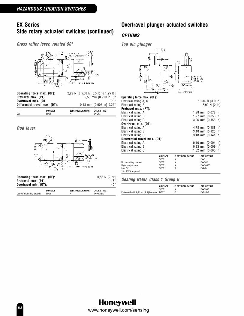
6 2www.honeywell.com/sensing
EX SeriesSide rotary actuated switches (continued)
Cross roller lever, rotated 90°
Operating force max. (OF): 2,22 N to 5,56 N [0.5 lb to 1.25 lb]Pretravel max. (PT): 5,56 mm [0.219 in] 8°Overtravel max. (OT 90°Differential travel max. (DT): 0,18 mm [0.007 in] 0.25°
CONTACT ELECTRICAL RATING CAT. LISTINGCW SPDT A EX-CR
Rod lever
Operating force max. (OF): 0,56 N [2 oz]Pretravel max. (PT): 18°Overtravel min. (OT): 40°
CONTACT ELECTRICAL RATING CAT. LISTINGCW/No mounting bracket SPDT A EX-AR1613
Overtravel plunger actuated switches
OPTIONS
Top pin plunger
Operating force max. (OF):Electrical rating A, C 13,34 N [3.0 lb]Electrical rating B 8,90 N [2 lb]Pretravel max. (PT):Electrical rating A 1,98 mm [0.078 in]Electrical rating B 1,27 mm [0.050 in]Electrical rating C 3,96 mm [0.156 in]Overtravel min. (OT):Electrical rating A 4,78 mm [0.188 in]Electrical rating B 3,18 mm [0.125 in]Electrical rating C 3,48 mm [0.141 in]Differential travel max. (DT):Electrical rating A 0,10 mm [0.004 in]Electrical rating B 0,23 mm [0.009 in]Electrical rating C 1,52 mm [0.060 in]
CONTACT ELECTRICAL RATING CAT. LISTINGSPDT A EX-Q
No mounting bracket SPDT A EX-Q62High temperature SPDT A EX-Q400*Low OF SPDT B EXA-Q*No ATEX approval
Sealing NEMA Class 1 Group BCONTACT ELECTRICAL RATING CAT. LISTINGSPDT A EX-Q800
Preleaded with 0,91 m [3 ft] leadwire DPDT C EXD-Q-3
HAZARDOUS LOCATION SWITCHES

6 3www.honeywell.com/sensing
Boot sealed
Operating force max. (OF):Electrical rating D 13,34 N [3.0 lb]Electrical rating B 15,57 N [3.5 lb]Pretravel max. (PT):Electrical rating D 1,98 mm [0.078 in]Electrical rating B 2,77 mm [0.109 in]Overtravel min. (OT):Electrical rating D 4,78 mm [0.188 in]Electrical rating B 3,18 mm [0.125 in]Differential travel max. (DT):Electrical rating D 0,10 mm [0.004 in]Electrical rating B 0,23 mm [0.009 in]
CONTACT ELECTRICAL RATING CAT. LISTINGSPDT D EX-N15
Class 1 Group B SPDT B EXA-N
Manually actuated
Operating force max. (OF): 11,1 N [2.5 lb]
CONTACT ELECTRICAL RATING CAT. LISTINGSPDT A EX-AR50
HAZARDOUS LOCATION SWITCHES
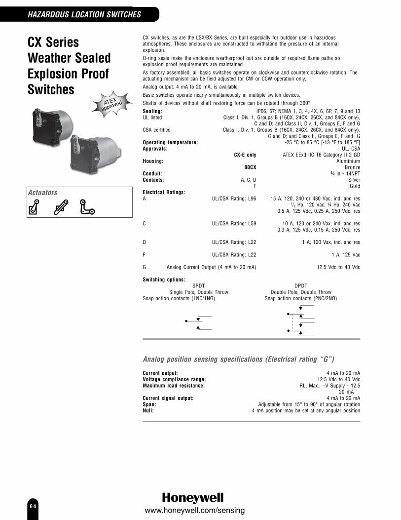
6 4www.honeywell.com/sensing
CX SeriesWeather SealedExplosion ProofSwitches
CX switches, as are the LSX/BX Series, are built especially for outdoor use in hazardousatmospheres. These enclosures are constructed to withstand the pressure of an internalexplosion.O-ring seals make the enclosure weatherproof but are outside of required flame paths soexplosion proof requirements are maintained.As factory assembled, all basic switches operate on clockwise and counterclockwise rotation. Theactuating mechanism can be field adjusted for CW or CCW operation only.Analog output, 4 mA to 20 mA, is available.Basic switches operate nearly simultaneously in multiple switch devices.Shafts of devices without shaft restoring force can be rotated through 360°.Sealing: IP66, 67; NEMA 1, 3, 4, 4X, 6, 6P, 7, 9 and 13UL listed Class I, Div. 1, Groups B (16CX, 24CX, 26CX, and 84CX only),
C and D; and Class II, Div. 1, Groups E, F and GCSA certified Class I, Div. 1, Groups B (16CX, 24CX, 26CX, and 84CX only),
C and D; and Class II, Groups E, F and GOperating temperature: -25 °C to 85 °C [-13 °F to 185 °F]Approvals: UL, CSA
CX-E only ATEX EExd IIC T6 Category II 2 GDHousing: Aluminium
80CX BronzeConduit: ¾ in - 14NPTContacts: A, C, D Silver
F GoldElectrical Ratings:A UL/CSA Rating: L96 15 A, 120, 240 or 480 Vac, ind. and res
1/8 Hp, 120 Vac; ¼ Hp, 240 Vac0.5 A, 125 Vdc, 0.25 A, 250 Vdc, res
C UL/CSA Rating: L59 10 A, 120 or 240 Vax, ind. and res0.3 A, 125 Vdc, 0.15 A, 250 Vdc, res
D UL/CSA Rating: L22 1 A, 120 Vax, ind. and res
F UL/CSA Rating: L22 1 A, 125 Vac
G Analog Current Output (4 mA to 20 mA) 12.5 Vdc to 40 Vdc
Switching options:SPDT DPDT
Single Pole, Double Throw Double Pole, Double ThrowSnap action contacts (1NC/1NO) Snap action contacts (2NC/2NO)
Analog position sensing specifications (Electrical rating “G”)
Current output: 4 mA to 20 mAVoltage compliance range: 12.5 Vdc to 40 VdcMaximum load resistance: RL, Max., –V Supply - 12.5
20 mACurrent signal output: 4 mA to 20 mASpan: Adjustable from 15° to 90° of angular rotationNull: 4 mA position may be set at any angular position
Actuators
ATEX
approved
HAZARDOUS LOCATION SWITCHES

6 5www.honeywell.com/sensing
Short housing
Standard housing
OPTIONS
HOUSING BASIC CONTACT ELECTRICAL SHAFT RESTORING CAT. LISTINGSIZE SWITCHES RATING FORCE TO CENTREShort BZ (2) SPDT A With 11CX2Short BZ (2) SPDT A Without 11CX12Short BZ (2) SPDT A With 11CX2EShort BZ (2) SPDT A Without 11CX12EShort BZ (2) SPDT F With 1172CX2Short BZ (2) SPDT F Without 1172CX12
Standard BZ (4) SPDT A With 21CX4Standard BZ (4) SPDT A Without 21CX14
UL listed for Class I, Group B (hydrogen atmospheres)HOUSING BASIC CONTACT ELECTRICAL SHAFT RESTORING CAT. LISTINGSIZE SWITCHES RATING FORCE TO CENTREStandard DT (2) DPDT C With 24CX2Standard DT (2) DPDT C Without 24CX12Short HS (2) SPDT D With 16CX2Short HS (2) SPDT D Without 16CX12Standard HS (4) SPDT D With 26CX4
Analog output, 4 mA to 20 mAHOUSING BASIC CONTACT ELECTRICAL SHAFT RESTORING CAT. LISTINGSIZE SWITCHES RATING FORCE TO CENTREShort None N/A G With 18CX0Short None N/A G Without 18CX10Short None N/A G Without 18CX10EStandard BZ (2) SPDT A, G With 281CX2Standard BZ (2) SPDT A, G Without 281CX12
Bronze housing for use in corrosiveenvironments80CX switches have rugged bronze housings which are resistant to salt waterand other corrosive environments. They comply with the NEMA 4Xrequirement for protection against corrosion, in addition to NEMAenclosure standards met by other CX switches. O-ring seals make theenclosure weather-proof, but are outside of required flame paths,maintaining explosion-proof requirements.
HOUSING BASIC CONTACT ELECTRICAL SHAFT RESTORING CAT. LISTINGSIZE SWITCHES RATING FORCE TO CENTREStandard BZ (2) SPDT A With 81CX2Standard BZ (4) SPDT A With 81CX4Standard BZ (4) SPDT A Without 81CX14Standard DT (2) DPDT C With 84CX2
Basic Switch Type BZ BA DT HSPretravel (max.)* 15° 15° 30° 30°Differential Travel (max.) 10° 10° 25° 20°Overtravel (min.)* 90° 90° 75° 75°Operating Torque (max.) 11.1 in lb/1,25 N m* May be modified in field to suit application requirements.
Note: Levers are ordered separately(see pages 71-73 for details)
Operating characteristicsNotes:Add the letter “A” to listings with side mounting holes tapped 5/16 (8).Example: 11CX2AAdd the letter “B” to listings with thru mounting holes tapped 3/8-24 (4).Example: 11CX2BAdd the letter “C” to listings for low temperature (-40 °C/°F) applications.Example: 11CX2CAdd “D01” to specify a “direct-couple” listing with 3/8 in. dia by 3/4 in. longflatted shaft.Example: 11CX2-D01Add the letter “E” to listings for European Atex approvals.Example: 11CX2EFor Replacement Basic Switch Assemblies, change the first number in thelisting to “9”.Example: 11CX2 becomes 91CX2
HAZARDOUS LOCATION SWITCHES
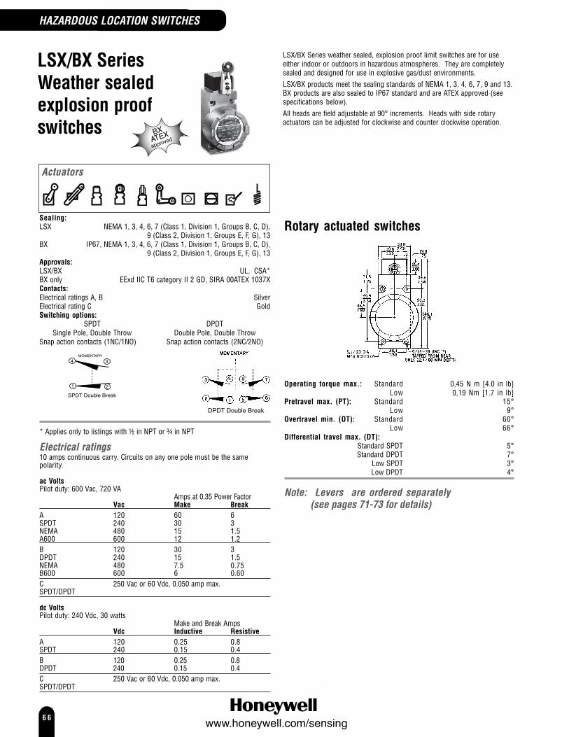
6 6www.honeywell.com/sensing
LSX/BX SeriesWeather sealedexplosion proofswitches
LSX/BX Series weather sealed, explosion proof limit switches are for useeither indoor or outdoors in hazardous atmospheres. They are completelysealed and designed for use in explosive gas/dust environments.LSX/BX products meet the sealing standards of NEMA 1, 3, 4, 6, 7, 9 and 13.BX products are also sealed to IP67 standard and are ATEX approved (seespecifications below).All heads are field adjustable at 90° increments. Heads with side rotaryactuators can be adjusted for clockwise and counter clockwise operation.
Sealing:LSX NEMA 1, 3, 4, 6, 7 (Class 1, Division 1, Groups B, C, D),
9 (Class 2, Division 1, Groups E, F, G), 13BX IP67, NEMA 1, 3, 4, 6, 7 (Class 1, Division 1, Groups B, C, D),
9 (Class 2, Division 1, Groups E, F, G), 13Approvals:LSX/BX UL, CSA*BX only EExd IIC T6 category II 2 GD, SIRA 00ATEX 1037XContacts:Electrical ratings A, B SilverElectrical rating C GoldSwitching options:
SPDT DPDTSingle Pole, Double Throw Double Pole, Double Throw
Snap action contacts (1NC/1NO) Snap action contacts (2NC/2NO)
SPDT Double Break
DPDT Double Break
* Applies only to listings with ½ in NPT or ¾ in NPT
Electrical ratings10 amps continuous carry. Circuits on any one pole must be the samepolarity.
ac VoltsPilot duty: 600 Vac, 720 VA
Amps at 0.35 Power FactorVac Make Break
A 120 60 6SPDT 240 30 3NEMA 480 15 1.5A600 600 12 1.2B 120 30 3DPDT 240 15 1.5NEMA 480 7.5 0.75B600 600 6 0.60C 250 Vac or 60 Vdc, 0.050 amp max.SPDT/DPDT
dc VoltsPilot duty: 240 Vdc, 30 watts
Make and Break AmpsVdc Inductive Resistive
A 120 0.25 0.8SPDT 240 0.15 0.4B 120 0.25 0.8DPDT 240 0.15 0.4C 250 Vac or 60 Vdc, 0.050 amp max.SPDT/DPDT
Rotary actuated switches
Operating torque max.: Standard 0,45 N m [4.0 in lb]Low 0,19 Nm [1.7 in lb]
Pretravel max. (PT): Standard 15°Low 9°
Overtravel min. (OT): Standard 60°Low 66°
Differential travel max. (DT):Standard SPDT 5°Standard DPDT 7°
Low SPDT 3°Low DPDT 4°
Note: Levers are ordered separately(see pages 71-73 for details)
Actuators
BXATEXapproved
HAZARDOUS LOCATION SWITCHES

6 7www.honeywell.com/sensing
OPTIONS
Side rotary
50,82.0039,6
1.5619,00.75
31,91.25
49,31.94
25,41.00
LSXOperating temperature: -12 °C to 121 °C [10 °F to 250 °F]
CONTACT CONDUIT ELECTRICAL RATING CAT. LISTINGSPDT ½ in - 14NPT A LSXA3KSPDT 20 mm A LSX4A3KSPDT ¾ in - 14NPT A LSXA4KSPDT ½ in - 14NPT C LSXA3EDPDT ¾ in - 14NPT B LSXA4LDPDT 20 mm B LSX4A4LDPDT ½ in - 14NPT B LSXA7L
Low DT SPDT ½ in - 14NPT A LSXP3K
BX (ATEX approved)Operating temperature: -40 °C to 70 °C [ -40 °F to 158 °F]
CONTACT CONDUIT ELECTRICAL RATING CAT. LISTINGSPDT ½ in - 14NPT A BXA3KSPDT 20 mm A BX4A3KDPDT ¾ in - 14NPT B BXA4L
LSXOperating temperature: -1 °C to 121 °C [30 °F to 250 °F]
CONTACT CONDUIT ELECTRICAL RATING CAT. LISTINGLow DT/Low torque SPDT ½ in - 14NPT A LSXH3KLow DT/Low torque DPDT ¾ in - 14NPT B LSXH4LLow torque SPDT ½ in - 14NPT A LSXR3KLow torque DPDT ¾ in - 14NPT B LSXR4L
BX (ATEX approved)Operating temperature: -40 °C to 70 °C [ -40 °F to 158 °F]
CONTACT CONDUIT ELECTRICAL RATING CAT. LISTINGLow torque SPDT ½ in - 14NPT A BXR3KLow torque SPDT ½ in - 14NPT C BXR3ELow torque DPDT ¾ in - 14NPT C BXR4S
Centre neutralOperating torque max. : 0,45 N m [4.0 in lb]Pretravel max. (PT): 18°Overtravel min. (OT): 57°Differential travel max. (DT): 10°
LSXOperating temperature: -1 °C to 121 °C [30 °F to 250 °F]
CONTACT CONDUIT ELECTRICAL RATING CAT. LISTINGDPDT ¾ in - 14NPT B LSXM4NDPDT 20 mm B LSX4M4N
Maintained contactOperating torque max.: 0,45 N m [4.0 in lb]Pretravel max. (PT): 65°Overtravel min. (OT): 20°Differential travel max. (DT): SPDT 30°
DPDT 35°
LSXOperating temperature: -1 °C to 121 °C [30 °F to 250 °F]
CONTACT CONDUIT ELECTRICAL RATING CAT. LISTINGMaintained SPDT ½ in - 14NPT A LSXN3KMaintained DPDT ¾ in - 14NPT B LSXN4LMaintained DPDT ½ in - 14NPT B LSXN7L
BX (ATEX approved)Operating temperature: -40 °C to 70 °C [ -40 °F to 158 °F]
CONTACT CONDUIT ELECTRICAL RATING CAT. LISTINGMaintained SPDT ½ in - 14NPT A BXN3KMaintained DPDT ¾ in - 14NPT B BXN4L
Top rotary
Operating torque max.: 0,28 N m [2.5 in lb]Pretravel max. (PT): 25°Overtravel min. (OT): 100°Differential travel max. (DT): SPDT 10°
DPDT 12°
LSXOperating temperature: -1 °C to 121 °C [30 °F to 250 °F]
CONTACT CONDUIT ELECTRICAL RATING CAT. LISTINGSPDT ½ in - 14NPT A LSXB3KDPDT ¾ in - 14NPT B LSXB4L
HAZARDOUS LOCATION SWITCHES

6 8www.honeywell.com/sensing
LSX/BX Series (continued)Plunger actuated switches
Top plungers
Operating force max. (OF): 17,79 N [4 lb]Pretravel max. (PT): 1,78 mm [0.07 in]Overtravel min. (OT): 4,83 mm [0.19 in]Differential travel max. (DT):SPDT 0,38 mm [0.015 in]DPDT 0,51 mm [0.02 in]
OPTIONS
Top pin plunger
Operating point: 58,5 mm ± 0,76 mm[2.305 in ± 0.03 in]
LSXOperating temperature: -12 °C to 93 °C [10 °F to 200 °F]
CONTACT CONDUIT ELECTRICAL RATING CAT. LISTINGSPDT ½ in - 14NPT A LSXC3KSPDT 20 mm A LSX4C3KDPDT ¾ in - 14NPT B LSXC4L
BX (ATEX approved)Operating temperature: -40 °C to 70 °C [ -40 °F to 158 °F]
CONTACT CONDUIT ELECTRICAL RATING CAT. LISTINGSPDT 20 mm A BX4C3KDPDT ¾ in - 14NPT B BXC4LDPDT 20 mm B BX4C4L
Top pin plunger, adjustable
21,6(0.85)
7,9(0.31)
Max.operating point
72,0(2,83)
Min.operating point
65,7(2,59)
Operating point: 65,66 mm to 72,01 mm[2.585 in to 2.835 in]
LSXOperating temperature: -12 °C to 93 °C [10 °F to 200 °F]
CONTACT CONDUIT ELECTRICAL RATING CAT. LISTINGSPDT ½ in - 14NPT A LSXV3K
Top roller plungerHead can be set at 90° increments for cam or slide actuation
Operating point: 68,6 mm ± 1.00 mm [2.700 in ± 0.04 in]
LSXOperating temperature: -12 °C to 93 °C [10 °F to 200 °F]
CONTACT CONDUIT ELECTRICAL RATING CAT. LISTINGSPDT ½ in - 14NPT A LSXD3KSPDT 20 mm A LSX4D3KDPDT ¾ in - 14NPT B LSXD4L
BX (ATEX approved)Operating temperature: -40 °C to 70 °C [ -40 °F to 158 °F]
CONTACT CONDUIT ELECTRICAL RATING CAT. LISTINGSPDT 20 mm A BX4D3K
BXATEXapproved
HAZARDOUS LOCATION SWITCHES

6 9www.honeywell.com/sensing
Side plungers
Operating force max. (OF): 26,69 N [6 lb]Pretravel max. (PT): 2,54 mm [0.10 in]Overtravel min. (OT): 4,83 mm [0.19 in]Differential travel max. (DT): 1,14 mm [0.045]
OPTIONS
Side pin plunger
50,82.0039,6
1.5619,00.75
49,31.94
25,41.00
Operating point: 33,0 mm [1.30 in]
LSXOperating temperature: -12 °C to 93 °C [10 °F to 200 °F]
CONTACT CONDUIT ELECTRICAL RATING CAT. LISTINGSPDT ½ in - 14NPT A LSXE3KDPDT ¾ in - 14NPT B LSXE4L
Side roller plungerRoller may be set in vertical or horizontal position for cam or slideactuation
Operating point: 44,1 mm [1.735 in]
LSXOperating temperature: -12 °C to 93 °C [10 °F to 200 °F]
CONTACT CONDUIT ELECTRICAL RATING CAT. LISTINGSPDT ½ in - 14NPT A LSXF3K
BX (ATEX approved)Operating temperature: -40 °C to 70 °C [ -40 °F to 158 °F]
CONTACT CONDUIT ELECTRICAL RATING CAT. LISTINGSPDT ½ in - 14NPT A BXF3K
Wobble actuated switches
OPTIONS
Plastic rod
Operating force max. (OF): 2,78 N [10 oz]Pretravel max. (PT): 25,4 mm [1.0 in]
LSXOperating temperature: -12 °C to 93 °C [10 °F to 200 °F]
CONTACT CONDUIT ELECTRICAL RATING CAT. LISTINGSPDT ½ in - 14NPT A LSXJ3K-7ADPDT ¾ in - 14NPT B LSXJ4L-7A
Cat whisker
Operating force max. (OF): 1,39 N [5 oz]Pretravel max. (PT): 50,8 mm [2.0 in]
LSXOperating temperature: -12 °C to 93 °C [10 °F to 200 °F][10 °F to 200
°F]
CONTACT CONDUIT ELECTRICAL RATING CAT. LISTINGSPDT ½ in - 14NPT A LSXK3K-8A
HAZARDOUS LOCATION SWITCHES

7 0www.honeywell.com/sensing

7 1www.honeywell.com/sensing
LeversSeparate levers must be ordered with siderotary types. The table provides a crossreference between product families and thelever order/reference numbers. The followingpages describe the levers. Illustrations are forreference only. Exact mounting drawings anddimensions are available from your local salesoffice or from the website below.Levers lock in any position, 360° around theshaft. Rollers may be mounted on the front orback of the lever.All levers are supplied with cap screws.Explosion proof switchesBecause of explosion proof requirements, onlynylon rollers or other non sparking materialshould be selected. BX/LSX, CX and EXplunger and cat whisker types are of nonsparking material. Do not mix or substitute.
Specification (unless statedotherwise)Lever radius/length: 1.5 in [38,1 mm]Roller Diameter: 0.75 in [19,1 mm]Roller Width: 0.25 in [6,35 mm]-EX 0.312 in [7,92 mm]
Note:Not all levers are compatiblewith all switches
LEVERS
CAT. ROLLER LIMIT SWITCH SERIES EXPLOSION PROOF SERIESLISTING MATERIAL GLA HDLS LS2 LS BX/LSX CX EX6PA57 Aluminium6PA63 Stainless steel 6PA69 Spring rod6PA80 Steel6PA82 Steel6PA102 Nylon6PA144 Ball bearingGLZ51A NylonGLZ51B SteelGLZ52A NylonGLZ52B SteelGLZ54J AluminiumGLZ55B SteelLSZ51 N/ALSZ51A NylonLSZ51B SteelLSZ51C NylonLSZ51D SteelLSZ51W RubberLSZ51Y RubberLSZ52 N/ALSZ52A NylonLSZ52B SteelLSZ52C NylonLSZ52D SteelLSZ52J NylonLSZ52K NylonLSZ52M NylonLSZ52N NylonLSZ52W RubberLSZ52Y RubberLSZ53A NylonLSZ53B SteelLSZ53D SteelLSZ53E NylonLSZ53P SteelLSZ53S NylonLSZ53U SteelLSZ54 N/ALSZ54M AluminiumLSZ54N Stainless steelLSZ54R Spring wireLSZ54V CableLSZ55 N/ALSZ55A NylonLSZ55B SteelLSZ55C NylonLSZ55D SteelLSZ55W RubberLSZ55Y RubberLSZ61 NylatronLSZ67AA RubberLSZ68 Delrin6PA5-EX Bronze6PA127-EX Nylon6PA130-EX Bronze6PA131-EX Bronze6PA136-EX Aluminium6PA138-EX Nylon6PA142-EX Bronze6PA204-EX NylonStainless steelleversLS2Z51A NylonLS2Z51B SteelLS2Z52A NylonLS2Z52B SteelLS2Z54N Steel

7 2www.honeywell.com/sensing
OPTIONS
Standard fixed lever
MOUNTED ON CAT. LISTINGWithout roller LSZ51*Nylon roller Front LSZ51A*Metal roller Front LSZ51BNylon roller Back LSZ51C*Metal roller Back LSZ51DNylon roller Front GLZ51AMetal roller Front GLZ51BBronze roller Front 6PA5-EX*Nylon roller Front 6PA127-EX*Ball bearing roller Front 6PA144
Offset fixed lever
MOUNTED ON CAT. LISTINGWithout roller LSZ55*Nylon roller Back LSZ55A*Metal roller Back LSZ55BNylon roller Front LSZ55C*Metal roller Front LSZ55DMetal roller Front GLZ55B
Adjustable lever
Operating radius/length: 1.5 in to 3.5 in[38,1 mm to 88,9 mm]
-EX 1.69 in to 3.0 in[42,9 mm to 76,2 mm]
MOUNTED ON CAT. LISTINGAdjustable lever, without roller LSZ52Nylon roller Back LSZ52A*Metal roller Back LSZ52BNylon roller Front LSZ52C*Metal roller Front LSZ52DNylon roller,Ø 1.0 in [25,4] x 0.5 in [12,7 mm] Front LSZ52J*Nylon roller, Ø 1.5 in [38,1] Front LSZ52K*Nylon roller, Ø 2.0 in [50,8] Front LSZ52M*Nylon roller, 0.5 in wide [12,7 mm] Front LSZ52N*Nylon roller Back GLZ52AMetal roller Back GLZ52BNylon roller,Ø 1.0 in [25,4] x 0.5 in [12,7 mm] Front 6PA138-EX*
One way roller lever
RADIUS/LENGTH CAT. LISTINGBronze roller, clockwise 1.56 in [39,6 mm] 6PA130-EX*
Bronze roller, counter clockwise1.56 in [39,6 mm] 6PA142-EX*
Perpendicular (cross) roller lever
RADIUS/LENGTH CAT. LISTINGBronze roller 1.81 in [46,0mm] 6PA131-EX*
Yoke lever
MOUNTED ON CAT. LISTINGNylon roller Front/Back LSZ53AMetal roller Front/Back LSZ53BMetal roller Front/Front LSZ53DNylon roller Back/Front LSZ53E*Metal roller Back/Back LSZ53PNylon roller Back/Back LSZ53S*Metal roller Back/Front LSZ53UMetal roller Front/Back 6PA80Metal roller Front/Front 6PA82Nylon roller Front/Front 6PA102
Adjustable rod
RADIUS/LENGTH CAT. LISTINGHub only LSZ54*Aluminium rod 5.5 in [139,7 mm] LSZ54M*Stainless steel rod 13.0 in [330,2 mm] LSZ54NAluminium, spring only 12.0 in [305 mm] LSZ54RAluminium, flexible cable 4.8 in [122 mm] LSZ54VAluminium rod 7.9 in [200 mm] GLZ54JStainless steel rod 13.0 in [330,2 mm] 6PA63Aluminium rod 5.3 in [134,1 mm] 6PA136-EX*
Adjustable rod, nylon roller
RADIUS/LENGTH CAT. LISTINGAluminium rod, nylon roler 12.5 in [317,5 mm] 6PA204-EX*
Spring rod
RADIUS/LENGTH CAT. LISTINGØ 0.25 in [6,35 mm] 12.0 in [305 mm] LSZ68Ø 0.17 in [4,32 mm] 7.4 in [188 mm] 6PA69
LEVERS
Note: Not all levers are compatible with all switches
* denotes lever suitable for Explosion Proof Series switches

7 3www.honeywell.com/sensing
NOTICE **Large rubber rollers and conveyor roller armBecause of the lever’s mass, the limit switch should bemounted with the lever facing down. This will enablegravity to help restore the switch to the free position.
Flexible loop
RADIUS/LENGTH CAT. LISTINGFlexible loop 6.0 in [152 mm] LSZ61
Hand operated button
CAT. LISTINGØ 1.5 in [38,1 mm] 6PA57
**Large rubber roller, fixedlever
CAT. LISTINGØ 1.6 in X 0.50 in wide roller LSZ51W[40,6 mm X 12,7 mm] Ø 2 in X 0.50 in wide roller LSZ51Y[50,8 mm X 12,7 mm]
**Large rubber roller, fixed offsetlever
CAT. LISTINGØ 1.6 in X 0.50 in wide roller LSZ55W[40,6 mm X 12,7 mm]Ø 2 in X 0.50 in wide roller LSZ55Y[50,8 mm X 12,7 mm]
**Large rubber roller, adjustablelever
CAT. LISTINGØ 1.6 in X 0.50 in wide roller LSZ52W[40,6 mm X 12,7 mm]Ø 2 in X 0.50 in wide roller LSZ52Y[50,8 mm X 12,7 mm]
**Conveyor roller arm
Operating radius/length: 6.78 in [172,2 mm]
CAT. LISTINGPlastic roller, 1.5 in Ø X 3.8 in long LSZ67AA[38,1 mm X 96,5 mm]
LEVERS
Stainless steel leversRoller Diameter: 0.75 in [19,1 mm]Roller Width: 0.25 in [6,35 mm]
OPTIONS
Standard fixed lever
Operating radius/length: 1.5 in [38,1 mm]
MOUNTED ON CAT. LISTINGNylon roller Front LS2Z51A*Stainless steel roller Front LS2Z51B
Adjustable lever
Operating radius/length: 1.5 in to 3.5 in[38,1 mm to 88,9 mm]
MOUNTED ON CAT. LISTINGNylon roller Back LS2Z52A*Stainless steel roller Back LS2Z52B
Adjustable rod
Operating radius/length: 13 in [330,2 mm]
CAT. LISTINGLS2Z54N
Note: Not all levers are compatible with all switches
* denotes lever suitable for Explosion Proof Series switches

7 4www.honeywell.com/sensing
MY2 Series
OPTIONS
Standard, PCB Terminal, DPDT
3,5[0.14]
1,0
[0.0
4]3,
3[0
.13]
0,5
[0.0
2]
0,5[0.02]
Max. 36,0 [1.42] 6,0[0.24]
Max. 21,5[0.85]
6,3
[0.2
5]
Max
. 28,
0[1
.10]
COIL INPUT VOLTAGE MAX. CONTACT RATING CAT. LISTING110/120 Vac 250 Vac/5 amp SZR-MY2-1P-AC110-120V220/240 Vac 250 Vac/5 amp SZR-MY2-1P-AC220V-240V24 Vdc 125 Vdc/1 amp SZR-MY2-1P-DC24V
POWER RELAYS
SZR-MYSeries PowerRelay
Solder/Plug-In Terminal, DPDT
8 - O 1,2 [0.05] x 3 Holes
2,6
[0.1
0]0,
5[0
.02]
0,5[0.02]
6,0[0.24]
Max. 36,0 [1.42]
Max. 21,5[0.85]
Max
. 28,
0 [1
.10]
6,3
[0.2
5]
StandardCOIL INPUT VOLTAGE MAX. CONTACT RATING CAT. LISTING110/120 Vac 250 Vac/5 amp SZR-MY2-1-AC110-120V220 Vac 250 Vac/5 amp SZR-MY2-1-AC220V12 Vdc 125 Vdc/1 amp SZR-MY2-1-DC12V24 Vdc 125 Vdc/1 amp SZR-MY2-1-DC24V
LED IndicatorCOIL INPUT VOLTAGE MAX. CONTACT RATING CAT. LISTING110/120 Vac 250 Vac/5 amp SZR-MY2-N1-AC110-120V220 Vac 250 Vac/5 amp SZR-MY2-N1-AC220V12 Vdc 125 Vdc/1 amp SZR-MY2-N1-DC12V24 Vdc 125 Vdc/1 amp SZR-MY2-N1-DC24V
Diode ProtectionCOIL INPUT VOLTAGE MAX. CONTACT RATING CAT. LISTING24 Vdc 125 Vdc/1 amp SZR-MY2-D1-DC24V
LED Indicator/Diode ProtectionCOIL INPUT VOLTAGE MAX. CONTACT RATING CAT. LISTING24 Vdc 125 Vdc/1 amp SZR-MY2-X1-DC24V
SZR-MY Series general-purpose power relays are designed for a widerange of potential applications including power, as well as logic control,for factory machines and control panels.SZR-MY Series relays have a small package design for multipleapplication needs. Relays are available in two configurations: DPDT witha 5 A load and 4PDT with a 3 A load. One standard and three optionsare available: LED indicator, internal surge protection diode, and LEDindicator/diode protection.
Current rating (SZR-MY2): 5 ACurrent rating (SZR-MY4): 3 AContact resistance: 50 mOhm max.Contact material: Fine silverAgency approvals: UL, CE, CSAOperate time: 20 ms max.Release time: 20 ms max.Ambient temperature: -25 °C to 75 °C [-13 °F to 167 °F]Ambient humidity: 45% RH to 85% RHSwitching options: DPDT, 4PDT

7 5www.honeywell.com/sensing
POWER RELAYS
Solder/Plug-In Terminal, 4PDT
14 - O 1.2 [0.05] x 3 Holes
0,5[0.02]
Max. 36,0 [1.42] 6,0[0.24]
Max. 21,5[0.85]
Max
. 28,
0[1
.10]
6,3
[0.2
5]
0,5
[0.0
2]2,
6[0
.10]
StandardCOIL INPUT VOLTAGE MAX. CONTACT RATING CAT. LISTING110/120 Vac 250 Vac/3 amp SZR-MY4-1-AC110-120V220 Vac 250 Vac/3 amp SZR-MY4-1-AC220V12 Vdc 125 Vdc/0.6 amp SZR-MY4-1-DC12V24 Vdc 125 Vdc/0.6 amp SZR-MY4-1-DC24V
LED IndicatorCOIL INPUT VOLTAGE MAX. CONTACT RATING CAT. LISTING110/120 Vac 250 Vac/3 amp SZR-MY4-N1-AC110-120V220 Vac 250 Vac/3 amp SZR-MY4-N1-AC220V12 Vdc 125 Vdc/0.6 amp SZR-MY4-N1-DC12V24 Vdc 125 Vdc/0.6 amp SZR-MY4-N1-DC24V
Diode ProtectionCOIL INPUT VOLTAGE MAX. CONTACT RATING CAT. LISTING24 Vdc 125 Vdc/0.6 amp SZR-MY4-D1-DC24V
LED Indicator/Diode ProtectionCOIL INPUT VOLTAGE MAX. CONTACT RATING CAT. LISTING24 Vdc 125 Vdc/0.6 amp SZR-MY4-X1-DC24V
MY4 Series
OPTIONS
Standard, PCB Terminal, 4PDT
3,5[0.14]
3,3
[0.1
3]1,0
[0.0
4]0,
5[0
.02]
0,5[0.02]
5,0[0.20]
Max. 36,0 [1.42]
Max. 21,5[0.85]
6,3
[0.2
5]M
ax. 2
8,0
[1.1
0]
COIL INPUT VOLTAGE MAX. CONTACT RATING CAT. LISTING110/120 Vac 250 Vac/3 amp SZR-MY4-1P-AC110-120V220/240 Vac 250 Vac/3 amp SZR-MY4-1P-AC220V-240V24 Vdc 125 Vdc/0.6 amp SZR-MY4-1P-DC24V

7 6www.honeywell.com/sensing
POWER RELAYS
SZR-LY Series Power Relay
SZR-LY Series general-purpose power relays are designed for a widerange of potential applications including power, as well as logic control,for factory machines and control panels.SZR-LY Series relays break 10 A loads are often ideal for control panelsthat require stable and reliable relays.One standard and three options are available: LED indicator, internalsurge protection diode, and LED indicator/diode protection.
Current rating: 10 AContact resistance: 50 mOhm max.Contact material: Silver cadium oxideAgency approvals: UL, CE, CSAOperating frequency: 18,000 operations/hour (mechanical)
1,800 operations/hour (electrical)Operate time: 25 ms max.Release time: 25 ms max.Ambient temperature: -25 °C to 70 °C [-13 °F to 158 °F]Ambient humidity: 45% RH to 85% RHSwitching options: DPDT, 4PDT
LY2 Series
OPTIONS
Standard, PCB Terminal, DPDT
0,5
[0.0
2]2,
0[0
.08]
1,0[0.04]
4,5[0.18]
Max. 36,0 [1.42]Max. 21,5 [0.85]
Max
. 28,
0 [1
.10]
5,75
[0.2
3]
COIL INPUT VOLTAGE MAX. CONTACT RATING CAT. LISTING110/120 Vac 250 Vac/10 amp SZR-LY2-1P-AC110-120V24 Vdc 125 Vdc/2 amp SZR-LY2-1P-DC24V
Solder/Plug-In Terminal, DPDT
Max. 36,0 [1.42]0,
5[0
.02]
5,0
[0.2
0]
3,0 [0.12]
6,4 [0.26] Max. 21,5[0.85]
5,75
[0.2
3]M
ax. 2
8,0
[1.1
0]
14 - O 3,0 [0.12]
StandardCOIL INPUT VOLTAGE MAX. CONTACT RATING CAT. LISTING110/120 Vac 250 Vac/10 amp SZR-LY2-1-AC110-120V220 Vac 250 Vac/10 amp SZR-LY2-1-AC220V12 Vdc 125 Vdc/2 amp SZR-LY2-1-DC12V24 Vdc 125 Vdc/2 amp SZR-LY2-1-DC24V
LED IndicatorCOIL INPUT VOLTAGE MAX. CONTACT RATING CAT. LISTING110/120 Vac 250 Vac/10 amp SZR-LY2-N1-AC110-120V220 Vac 250 Vac/10 amp SZR-LY2-N1-AC220V12 Vdc 125 Vdc/2 amp SZR-LY2-N1-DC12V24 Vdc 125 Vdc/2 amp SZR-LY2-N1-DC24V
Diode ProtectionCOIL INPUT VOLTAGE MAX. CONTACT RATING CAT. LISTING24 Vdc 125 Vdc/2 amp SZR-LY2-D1-DC24V
LED Indicator/Diode ProtectionCOIL INPUT VOLTAGE MAX. CONTACT RATING CAT. LISTING24 Vdc 125 Vdc/ 2 amp SZR-LY2-X1-DC24V

7 7www.honeywell.com/sensing
POWER RELAYS
Solder/Plug-In Terminal, 4PDT
14 - O 3.0 Holes
Max. 36,0 [1.42]6,4 [0.25]
3,0[0.12]
5,0
[0.2
0]
0,5
[0.0
2]
Max. 41,5 [1.63]
Max
. 28,
0 [1
.10]
StandardCOIL INPUT VOLTAGE MAX. CONTACT RATING CAT. LISTING110/120 Vac 250 Vac/10 amp SZR-LY4-1-AC110-120V220 Vac 250 Vac/10 amp SZR-LY4-1-AC220V12 Vdc 125 Vdc/2 amp SZR-LY4-1-DC12V24 Vdc 125 Vdc/2 amp SZR-LY4-1-DC24V
LED IndicatorCOIL INPUT VOLTAGE MAX. CONTACT RATING CAT. LISTING110/120 Vac 250 Vac/10 amp SZR-LY4-N1-AC110-120V220 Vac 250 Vac/10 amp SZR-LY4-N1-AC220V12 Vdc 125 Vdc/2 amp SZR-LY4-N1-DC12V24 Vdc 125 Vdc/2 amp SZR-LY4-N1-DC24V
Diode ProtectionCOIL INPUT VOLTAGE MAX. CONTACT RATING CAT. LISTING24 Vdc 125 Vdc/2 amp SZR-LY4-D1-DC24V
LED Indicator/Diode ProtectionCOIL INPUT VOLTAGE MAX. CONTACT RATING CAT. LISTING24 Vdc 125 Vdc/2 amp SZR-LY4-X1-DC24V
LY4 Series
OPTIONS
Standard, PCB Terminal, 4PDT
Max. 36,0 [1.42]
1,0[0.04]
4,5[0.18]
2,0
[0.0
8]
0,5
[0.0
2]
Max. 41,5 [1.63]
Max
. 28,
0 [1
.10]
COIL INPUT VOLTAGE MAX. CONTACT RATING CAT. LISTING110/120 Vac 250 Vac/10 amp SZR-LY4-1P-AC110-120V220/240 Vac 250 Vac/10 amp SZR-LY4-1P-AC220V-240V24 Vdc 125 Vdc/2 amp SZR-LY4-1P-DC24V

7 8www.honeywell.com/sensing
25,0 [0.99]
18,0[0.70]
15,6
[0.6
1]
45,0
[1.7
7]
35,2
[1.3
9]
3,9[0.15]
6,0[0.24]
4,2
[0.1
7]
62,0
[2.4
4]
30,0 [1.18]
26,0 [1.02]3,0
[0.1
2]
62,0
± 0
,1[2
.44
± .0
04]
2 - O 4,5 [0.18] Holes
2-M3 or 2-M4
Max
. 61,
0 [2
.40]
26,0[1.02]
MY2 Series Socket
TYPE POLES CAT. LISTINGRail socket 2 SZX-SMF-08N
MY4 Series Socket
TYPE POLES CAT. LISTINGRail socket 4 SZX-SMF-14N
30,0 [1.18]
26,0 [1.02]
3,0
[0.1
2]62
,0 [2
.44]
4,2
[0.1
7]
45,0
[1.7
7]
15,6
[0.6
1]
35,2
[1.3
9]
62,0
± 0
,1 [2
.44
± .0
04]
2 - O 4,5 [0.18] Holes
2-M3 or 2-M4
25,0 [0.99]
18,0[0.70]
Max
. 61,
0 [2
.40]
6,0[0.24] 3,9
[0.15] 26,0[1.02]
LY2 Series Socket
TYPE POLES CAT. LISTINGRail socket 2 SZX-SLF-08N
LY4 Series Socket
TYPE POLES CAT. LISTINGRail socket 4 SZX-SLF-14
2 - O 4,5 [0.18] Holes2 - M4
25,0 ± 0,2[0.99 ± .008]
19,0[0.75]
2,5
[0.1
0]
14,5[0.57]
25,0 [0.99]
4,2
[0.1
7]
30,0 [1.18]
26,0[1.02]
47,0
[1.8
5]
67,0
[2.6
4]
22,0 [0.87]
8,0[0.31]
Max
. 61,
0 [2
.40]
Max. 30,0 [1.18]
8,0[0.31]
35,5
[1.4
0]
69,0
± 0
,3[2
.72
± 0.
01]
36,0 ± 0,2[1.42 ± 0.008]
2-M43,4 [0.13]14-M3.5x8
7,0[0.28]
2 - O 6,0 [0.24]4,5
[0.18]
68,0
[2.6
8]
Max
. 78,
5 [3
.09]
Max. 45,5[1.79]
Max
. 66,
0 [2
.60]
POWER RELAYS

7 9www.honeywell.com/sensing
SAFETY SWITCHES
Electromechanical SafetySwitchesHoneywell is a worldwide leader in advanced switching and sensingtechnology - especially in the area of industrial safety. We offer bothelectromechanical safety switches and electronic safety sensors as well assafety control modules for safety applications in all categories of risk.Our diverse product line can help customers meet all of their machinesafety needs.
Honeywell products meet or exceed European machine safety standardsand have been approved (CE, INRS) for use in Europe for more than 25years. As North America moves toward harmonizing with globalstandards, machine builders and users can confidently turn to Honeywellfor compliant machine safety solutions. Our products are designed tomeet all applicable OSHA and ANSI standards.
Refer to pages 6 and 7 for more information about degrees ofprotection and electrical ratings.
Protective GuardingProtective guarding around a dangerous machine can be achieved withtamper-resistant safety switches. Safety switches incorporate positiveopening operation such that even a welded contact will be mechanicallybroken and a stop signaled. These switches monitor the position ofmoveable guards and doors, which are used to safeguard access toequipment and provide protection from ejected pieces, chips, projectiles oroil. These safeguards require a relatively low investment and can providereliable protection if they are regularly checked and maintained.
Cable Pull SwitchesCable-pull limit switches serve as a readily accessible means ofemergency stop for applications. These cable-pull devices are visible,accessible and easy to use and are designed to immediately open theemergency stop circuit when activated.
! WARNINGIMPROPER INSTALLATION
• Consult with local safety agencies and their requirementswhen designing a machine-control link, interface and allcontrol elements that affect safety.
• Strictly adhere to all installation instructions.
Failure to comply with these instructions could result indeath or serious injury.
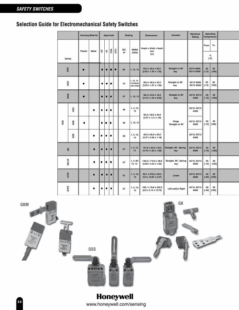
8 0www.honeywell.com/sensing
Selection Guide for Electromechanical Safety Switches
GSS
GKM GK
SAFETY SWITCHES
DimensionsElectrical
Rating
6769,4 x 34,0 x 16,0
[2.73 x 1.34 x 0.63]Straight or 90°
Straight or 90°
AC15, DC13A300
-25[-13]
85 [185]
GS
C
66AC15, DC13
A300
GS
D
66AC15, DC13
A600
GS
E
6683,0 x 65,0 x 30,0
[3.27 x 2.56 x 1.18]AC15, DC13
A300
67121,6 x 42,0 x 42,6[4.79 x 1.65 x 1.68]
Straight, 90°, Spring AC15, DC13 A600
-25[-13]
85 [185]
67149,0 x 110,0 x 48,8[5.85 x 4.33 x 1.92]
Straight, 90°, Spring AC15, DC13 A600
-25[-13]
85 [185]
671, 4, 12,
13
1, 4, 12, 13
99,1 x 276,2 x 65,2[3.9 x 10.87 x 2.57]
LinearAC15, DC13
A600 -40[-40]
85[185]
67165,1 x 79,8 x 325,9 [6.5 x 3.14 x 12.75]
Left and/or RightAC15, DC13
A600 -40[-40]
85[185]
GK
L/R
1CP
SG
KM
Hinge
83,0 x 30,5 x 30,0[3.27 x 1.2 x 1.18]
-25[-13]
85[185]
°C[°F]
From
CS
A IECIP
Operating Temperature
Housing Material
Series
Plastic MetalHeight x Width x Depth
mm[in]
Approvals
2CP
S
GS
S
NEMA(USA)C
E
UL
key
key
key
1, 4, 12, 13
1, 4, 12, 13
1, 4, 12,
1, 12, 13
13
1, 4, 6P, 12, 13
Sealing
1, 12, 13
Actuator
To
GK
CC
C
GK
NG
KE
66
67
1, 12, 13
1, 12, 134 (indooruse only)
Straight or 90°key
Straight or 90°key
AC15 A600,DC13 Q300
AC15 A600,DC13 Q300
-25[-13]
85 [185]
-25[-13]
85 [185]
90,0 x 40,0 x 33,0[3.55 x 1.57 x 1.30]
92,2 x 30,5 x 30,5[3.63 x 1.20 x 1.20]

8 1www.honeywell.com/sensing
GKL/GKR
2CPS
1CPS
SAFETY SWITCHES
Termination
Make Before Break
1NC/1NO
2NC/2NO
1NC/1NO
2NC/2NO
1NC1NC/ 1NO
1NC/1NO
2NC/1NO
2NC/2NO
3NC/1NO
4NC
M12 or Cable
85
85
86
Conduit
Conduit
Conduit
StandardHigh intensity
multi-cluster LED95
Conduit
Switching Options
Break Before Make
Slow Action
Snap Action
Pag
e N
um
berGold
Contacts (Low
Energy Options)
82Daisy chain capability
87
89
93Integral LED option
Special Features
Conduit
2NC 1NC/ 2NO
Conduit
Conduit
93
96

8 2www.honeywell.com/sensing
SAFETY SWITCHES
GKM SeriesGlobal MiniatureSafety KeyOperated Switch
Used alone as Category 1 safety components or, in conjunction with other safety switches and ourcomplete range of safety relays, it is possible to construct comprehensive protection schemes withCategory 2, 3 or 4 compliance.The preleaded versions are designed to allow rapid fit, easy cable routing and function testingwhich cut costs dramatically in OEM applications. Simple upgrade guarding solution for End Userapplications.Low energy basic switches are rated as follows:Operating Voltage Ue 1 Vdc to 60 Vdc or 1 Vac to 125 VacOperating Current Ie 1 mA to 50 mAExample of catalog listing using a low energy basic switch - GKMA19Mechanical life: > 1 millionSealing: IP66/67, EN 60529, NEMA 1, 12, 13Operating temperature: -25 °C to 85 °C [-13 °F to 185 °F]Approvals: CE, UL, CSA
AC15 B300DC13 Q300
Contacts: SilverLow energy Gold plated
Switching options: Slow action contacts1 Normally Closed/1 Normally Open, Break Before Make
1NC/1NO, BBM - GKMF 1NC/1NO, BBM, low energy - GKMA, B, C, D
3
3
4
4
2
2 1
1
1 Brown
4 Black
Blue 3
White 2
2 Normally Closed2NC - GKMF 2NC, low energy - GKMA, B, C, D
3
3
4
4
2
2 1
11 Brown
4 Black
Blue 3
White 2
Electrical ratings: IEC 60947-5-1/EN 60947-5-1
Designation & UtilizationRated operational current le (A) VA
Categoryat rated operational voltage Ue rating
120 V 240 V 380 V 480 V 500 V 600 V Make BreakAC15 A600 6 3 1,9 1,5 1,4 1,2 7200 720AC15 A300 6 3 - - - - 7200 720AC15 B300 3 1.5 - - - - 3600 360AC14 D300 0,6 0,3 - - - - 432 72
125 V 250 VDC13 Q300 0,55 0,27 69 69DC13 R300 0,22 0,1 28 28
12,8 / 0.504
1,6 / 0.058
17,2 / 0.67
37,4 / 1.47
2,3 / 0.69
22,0 / 0.866
34 max. / 0.34
32 max. / 1.26
16 max. / 0.63
Keyslot
Of key slot
10 max. /0.30
90˚ - Key shown in optionalactuating positions
Body style 'B'
0.366 0.177
2 X mounting holesfor M4 or #8 screws.Counter bored both sides08,3 X 4,5 deep.

8 3www.honeywell.com/sensing
SAFETY SWITCHES
OPTIONS
Side exit cable
CABLE LENGTH CONTACT CAT. LISTING1 m 2NC, low energy GKMA171 m 1NC/1NO, BBM, low energy GKMA192 m 1NC/1NO, BBM GKMA232 m 2NC GKMA262 m 2NC, low energy GKMA272 m 1NC/1NO, BBM, low energy GKMA293 m 1NC/1NO, BBM GKMA333 m 2NC GKMA363 m 2NC, low energy GKMA373 m 1NC/1NO, BBM, low energy GKMA39
Bottom exit cable
CABLE LENGTH CONTACT CAT. LISTING1 m 1NC/1NO, BBM GKMB131 m 2NC GKMB161 m 2NC, low energy GKMB171 m 1NC/1NO, BBM, low energy GKMB192 m 1NC/1NO, BBM GKMB232 m 2NC GKMB262 m 2NC, low energy GKMB272 m 1NC/1NO, BBM, low energy GKMB293 m 1NC/1NO, BBM GKMB333 m 2NC GKMB363 m 2NC, low energy GKMB373 m 1NC/1NO, BBM, low energy GKMB39
Side exit M12 dc micro-changeconnector
CONTACT CAT. LISTING1NC/1NO, BBM GKMC032NC GKMC062NC, low energy GKMC071NC/1NO, BBM, low energy GKMC09
Bottom exit M12 dc micro-changeconnector
CONTACT CAT. LISTING1NC/1NO, BBM GKMD032NC, low energy GKMD071NC/1NO, BBM, low energy GKMD09
Dual exit M12 dc micro-changeconnector
CONTACT CAT. LISTING1NC/1NO, BBM GKMF032NC GKMF062NC, low energy GKMF071NC/1NO, BBM, low energy GKMF09
KEY STYLE
Straight key
3,5 /0.138
2 + max. /0.945
6,4 min. / 0.252
12,8 / 0.504
Face 'A'
2,5 / 0.093
2 holes for M4or #8 screws
21,3 /0.638
22 /0.866
45 /1.77
15 /0.59
CAT. LISTINGStainless steel GKZ51M
90° key
6,4 min. /0.252
24 max. / 0.945
32 max. / 1.25
12,8 /0.504
14 max. /0.55
22 /0.866
Face 'A'
0.083
2 holes for M4or #8 screws with45˚ C' SK X 2,1 deep
CAT. LISTINGStainless steel GKZ52M

8 4www.honeywell.com/sensing
GSS SeriesHinge Mount SafetyLimit Switch
The Hinge Mount Safety Limit Switch is designed for use on machine access doors as an alternativesolution to key operated interlocks and safety limit switches. When the access door is opened, afollower pin (not supplied) slides down the slot in the actuator lever, forcing the actuator lever torotate and positively open the NC safety circuit to shut off the machine. Closing the access doorrotates the actuator lever to the reset position, closing the NC safety contacts.The Hinge Mount Safety Limit Switch minimizes alignment problems because it may be offset-mounted from the hinge point of the door. The tamper-resistant design and the positive openingcontacts provide an enhanced level of safety over the conventional spring-driven limit switches oftenused to monitor door position.Low Energy SwitchingIn today’s demanding age of low energy controls, electromechanical switches are frequently used tointerface directly with safety relays, PLCs and other low energy devices. To accommodate thisrequirement GSS offers a new gold plated contact version of the standard basic switch. Thisimproves reliability of switching at low currents and voltages by protecting the contact surfaces fromcontamination during operation or storage prior to use.Standard silver contacts have a disadvantage in that the contact surface may tarnish under certainenvironmental conditions, e.g. in the presence of moisture.Low energy basic switches are rated as follows:Operating Voltage Ue 1 Vdc to 60 Vdc or 1 Vac to 125 VacOperating Current Ie 1 mA to 50 mAExample of catalog listing using a low energy basic switch - GSCB33S2.
Switching options:GSC/D GSE
Snap action contacts (1NC/1NO) Slow action contacts (4NC)
Zb2221
1413
11 12
21 22
31 32 4Y
41 42
Slow action contacts (1NC/1NO) BBM Slow action contacts (2NC/2NO) BBM
Zb
21
13
22
14
11 12
21 22
33 34
2Y, 2X
43 44
Slow action contacts (2NC) Slow action contacts (3NC/1NO) BBM
11
21
12
22
2Y
2221
11 12
3231
44433Y, 1X
IEC 60947-5-1/EN 60947-5-1
Designation & UtilizationRated operational current le (A) VA
Categoryat rated operational voltage Ue rating
120 V 240 V 380 V 480 V 500 V 600 V Make BreakAC15 A600 6 3 1,9 1,5 1,4 1,2 7200 720AC15 A300 6 3 - - - - 7200 720AC15 B300 3 1.5 - - - - 3600 360AC14 D300 0,6 0,3 - - - - 432 72
125 V 250 VDC13 Q300 0,55 0,27 69 69DC13 R300 0,22 0,1 28 28
Electrical ratings:
SAFETY SWITCHES

8 5www.honeywell.com/sensing
GSC Metal bodyGSD Plastic bodyEN 50047Safety Standard
24,75 /0.97
14,5 /0.57
30 /1.18
conduitthread
ø 23 /ø 0.9
19,8 /0.78
22 /0.8720 /
0.78
3 /0.12
2,15 /0.08
R
55 /2.16
30,5 /1.20
3,5 /0.138
Mechanical life: up to 1 millionSealing: IP 66
(GSC)NEMA 1, 4, 12, 13
(GSD)NEMA 1, 12, 13
Operating temperature: -25 °C to 85 °C[-13 °F to 185 °F]
Approvals: IEC/EN 60947-5-1 AC15 A300 DC13 Q300
UL, CSA
ACTUATED SWITCHES
Rotated 90° to the leftfrom center
70 /2.7645 /1.77
104 /4.09
GSC - Metal bodyCONTACT CONDUIT CAT. LISTING1NC/1NO ½ in NPT GSCA01S11NC/1NO, BBM ½ in NPT GSCA03S12NC ½ in NPT GSCA06S12NC, low energy 20 mm GSCC36S1
GSD - Plastic bodyCONTACT CONDUIT CAT. LISTING1NC/1NO, BBM ½ in NPT GSDA03S12NC ½ in NPT GSDA06S11NC/1NO, BBM PG 13,5 GSDB03S12NC PG 13,5 GSDB06S11NC/1NO 20 mm GSDC01S1
Rotated 90° either direction fromcenter
12,5 /0.49
24,8 /0.97
2 /0.08
11,5 /0.45
5,1 /0.20
45 /1.77
70 /2.76
28 /
90 min. 90 min.
GSC - Metal bodyCONTACT CONDUIT CAT. LISTING1NC/1NO ½ in NPT GSCA01S21NC/1NO, BBM ½ in NPT GSCA03S22NC ½ in NPT GSCA06S22NC, low energy PG 13,5 GSCB36S2
GSD - Plastic bodyCONTACT CONDUIT CAT. LISTING1NC/1NO, BBM ½ in NPT GSDA03S22NC ½ in NPT GSDA06S21NC/1NO, BBM PG 13,5 GSDB03S22NC PG 13,5 GSDB06S21NC/1NO 20 mm GSDC01S2
Rotated 90° to the rightfrom center
180 MIN
GSC - Metal bodyCONTACT CONDUIT CAT. LISTING1NC/1NO ½ in NPT GSCA01S31NC/1NO, BBM ½ in NPT GSCA03S32NC ½ in NPT GSCA06S32NC, low energy PG 13,5 GSCB36S3
GSD - Plastic bodyCONTACT CONDUIT CAT. LISTING1NC/1NO, BBM ½ in NPT GSDA03S32NC ½ in NPT GSDA06S31NC/1NO, BBM PG 13,5 GSDB03S32NC PG 13,5 GSDB06S31NC/1NO 20 mm GSDC01S3
SAFETY SWITCHES

8 6www.honeywell.com/sensing
GSE EN 50047CompatibleSafety 3 Conduit MetalStandard
conduitthread
60 /2.37
4 /0.16
52 / 2.05
57 / 2.24
65 / 2.56
13,75 /0.54
2,5 / 0.1
R 2,15 /0.08
3 /0.12
20 / 0.79
22 / 0.87
40 / 1.57
42 / 1.65
23,8 / 0.94
ø 23 / ø 0.9
30 /1.18
12 /0.47
12,5 /0.49
24,75 /0.97
Mechanical life: up to 1 millionSealing: IP 66, NEMA/UL 1, 4, 12, 13Operating temperature: -25 °C to 85 °C
[-13 °F to 185 °F]Approvals: IEC/EN 60947-5-1
AC15 A300 DC13 Q300
UL, CSA
ACTUATED SWITCHES
Rotated 90° to the leftfrom center
70 /2.7645 /1.77
104 /4.09
CONTACT CONDUIT CAT. LISTING2NC/2NO, BBM ½ in NPT GSEA44S13NC/1NO, BBM ½ in NPT GSEA46S14NC, low energy 20 mm GSEC41S1
Rotated 90° either direction fromcenter
12,5 /0.49
24,8 /0.97
2 /0.08
11,5 /0.45
5,1 /0.20
45 /1.77
70 /2.76
28 /
90 min. 90 min.
CONTACT CONDUIT CAT. LISTING2NC/2NO, BBM ½ in NPT GSEA44S2
Rotated 90° to the rightfrom center
180 MIN
CONTACT CONDUIT CAT. LISTING2NC/2NO, BBM ½ in NPT GSEA44S3
SAFETY SWITCHES

8 7www.honeywell.com/sensing
SAFETY SWITCHES
GK SeriesDual Entry KeyOperated SafetyInterlock Switch
The GK Series is designed specifically for use on machines where key removal brings the machine toan immediate safe condition. It provides enhanced operator safety when added to hinged or slidingguard doors, screens and protective covers on enclosures. The GK Series is especially well suited forlarge door applications, typically in the automotive plant floor environment. Its heavy duty constructionwithstands harsh industrial environments where rugged, long-term durability is required.Nearly 1000 options are available in a simple to understand part number tree.A safety lockout device is also available for use with the GK Series. The lockout device (GKZL2) isspecifically designed to prevent a key from being inserted either manually, or by the access doorbeing closed while maintenance personnel are working on the machine. When inserted, the lockoutdevice can accommodate up to four padlocks to prevent unauthorised removal of the device.Mechanical life: up to 15 millionSealing: IP 67, NEMA/UL type 1, 4, 12,13Operating temperature: -25 °C to 85 °C [-13 °F to 185 °F]Approvals: CE, CSA, UL
AC15 A300/A600DC13 Q300
Contacts: SilverLow energy
GoldSwitching options:Snap action contacts (1NC/1NO) Snap action contacts (2NC/2NO)
13
21
14
22
Zb
13 14
21 22
11
23
12
2 4
Slow action contacts (1NC/1NO), BBM Slow action contacts (2NC)
Zb
21
13
22
14
21
11
22
12
2Y
Slow action contacts (2NC/2NO), BBM Slow action contacts (3NC/1NO)
21 22
13 14
23 24
11 12
2y,2x
21 22
31 32
43 44
11 12
3y,1x
Slow action contacts (4NC)
21 22
31 32
41 42
11 12
4y
IEC 60947-5-1/EN 60947-5-1
Designation & UtilizationRated operational current le (A) VA
Categoryat rated operational voltage Ue rating
120 V 240 V 380 V 480 V 500 V 600 V Make BreakAC15 A600 6 3 1,9 1,5 1,4 1,2 7200 720AC15 A300 6 3 - - - - 7200 720AC15 B300 3 1.5 - - - - 3600 360AC14 D300 0,6 0,3 - - - - 432 72
125 V 250 VDC13 Q300 0,55 0,27 69 69DC13 R300 0,22 0,1 28 28

8 8www.honeywell.com/sensing
Electrical ratings:
Head orientation
OPTIONS
Opening to front and top
9 /0.35
StandardCONDUIT CONTACT KEY CAT. LISTING1/2 NPT 1NC/1NO 90° GKBA1L71/2 NPT 1NC/1NO Up-down GKBA1L8-F11*1/2 NPT 1NC/1NO None GKBA1LX1/2 NPT 4NC 90° GKBA10L71/2 NPT 2NC/2NO, BBM Straight GKBA14L61/2 NPT 2NC/2NO, BBM 90° GKBA14L71/2 NPT 3NC/1NO, BBM Straight GKBA16L61/2 NPT 3NC/1NO, BBM 90° GKBA16L71/2 NPT 2NC/NO Straight GKBA2L61/2 NPT 4NC, low energy None GKBA30LX1/2 NPT 3NC/1NO, BBM, low energy None GKBA36LX1/2 NPT 1NC/1NO, BBM Straight GKBA3L61/2 NPT 1NC/1NO, BBM 90° GKBA3L71/2 NPT 2NC None GKBA6LXPG 13,5 2NC/2NO, BBM Straight GKBB14L6PG 13,5 1NC/1NO, BBM 90° GKBB3L7PG 13,5 2NC 90° GKBB6L720 mm 2NC/2NO, BBM 90° GKBC14L720 mm 1NC/1NO Straight GKBC1L620 mm 1NC/1NO 90° GKBC1L720 mm 1NC/1NO None GKBC1LX20 mm 2NC/NO None GKBC2LX20 mm 4NC, low energy None GKBC30LX20 mm 3NC/1NO, BBM, low energy None GKBC36LX20 mm 2NC None GKBC6LX
* fluorocarbon seal
Single LED indicatorCONDUIT CONTACT KEY CAT. LISTING1/2 NPT 1NC/1NO Straight GKCA1L61/2 NPT 1NC/1NO 90° GKCA1L71/2 NPT 1NC/1NO None GKCA1LX1/2 NPT 2NC None GKCA6LX1/2 NPT 4NC Straight GKCA10L61/2 NPT 2NC/2NO, BBM Straight GKCA14L61/2 NPT 2NC/2NO, BBM 90° GKCA14L71/2 NPT 2NC/2NO, BBM Side-side GKCA14L91/2 NPT 4NC, low energy None GKCA30LX1/2 NPT 3NC/1NO, BBM, low energy None GKCA36LX20 mm 1NC/1NO None GKCC1LX20 mm 2NC None GKCC6LX20 mm 4NC, low energy None GKCC30LX20 mm 3NC/1NO, BBM, low energy None GKCC36LX
Double LED indicatorCONDUIT CONTACT KEY CAT. LISTING1/2 NPT 2NC/2NO, BBM 90° GKDA14L7
32 /1.26
42,6 / 1.68
82 /3.23
121,6 / 4.79
30 /1.18
5,3 / 0.21
7,3 / 0.29
35 /1.38
45,71.80
42 /1.65
75,9 / 2.99
60 /2.36
31 /1.22
ø 5,3 /0.21
Opening to right and top
8 /0.32
Single LED indicatorCONDUIT CONTACT KEY CAT. LISTING1/2 NPT 2NC/2NO, BBM straight GKCA14M6
Opening to left and top
22 /0.87
Single LED indicatorCONDUIT CONTACT KEY CAT. LISTING1/2 NPT 2NC/2NO, BBM Straight GKCA14P61/2 NPT 1NC/1NO 90° GKCA1P7
Double LED indicatorCONDUIT CONTACT KEY CAT. LISTING1/2 NPT 2NC/2NO, BBM 90° GKDA14P7
SAFETY SWITCHES
GK Series (continued)

8 9www.honeywell.com/sensing
SAFETY SWITCHES
GKL/GKR SeriesDual Entry SolenoidKey OperatedSafety InterlockSwitch
The GKR (head to the right) and GKL (head to the left) products offer the user an unrivalled rangeof standard options.The GKR/GKL product is a key actuated device incorporating a key trapping mechanism. Theswitch is used on machinery where instant stop and access to the machinery is either impossible(due to the momentum of the machine) or impractical (due to tool or machine damage orscrapped product if the current machine cycle is interrupted).The switch incorporates an optional manual override feature which allows removal of the key foremergency access.Over 1000 options are available in a simple to understand part number tree.A safety lockout device is also available for use with the GKR/GKL Series. The lockout device (GKZL2) isspecifically designed to prevent a key from being inserted either manually, or by the access door beingclosed while maintenance personnel are working on the machine. When inserted, the lockout devicecan accommodate up to four padlocks to prevent unauthorised removal of the device.Mechanical life: up to 1 millionSealing: IP 68, NEMA/UL type 1, 4, 6P, 12,13Operating temperature: -25 °C to 40 °C [-13 °F to 104 °F]Approvals: CE, CSA, UL
AC15 A300/A600DC13 Q300
Contacts: SilverLow energy Gold-plated
Switching options:
Snap ActionType 11NC/1NO Direct Opening
Zb2221
1413
Slow ActingType 3 Type 14/151NC/1NO, Break before make (BBM) 2NC/2NO, Break before make (BBM)
Zb
2221
1413
11 12
21 22
33 34
2Y, 2X
43 44
2 Slow ActingType 36 Type 403NC/1NO, Break before make (BBM),low energy 4NC
2221
11 12
3231
44433Y, 1X
11 12
21 22
31 32 4Y
41 42
Type 44 Type 462NC/2NO, Break before make (BBM) 3NC/1NO, Break before make (BBM)
2Y,2X
43 44
2221
11 12
3433
43 44
31 32
2221
11 12
3Y,1X

9 0www.honeywell.com/sensing
GKL/GKR Series (continued)Key: Type 6 Straight
Type 9 Side - side, spring loadedType X No key
Latching mechanism: Type A Mechanical (solenoid unlockwith screwdriver)
Type B Mechanical (without override)Type S Electrical (solenoid unlock with
screwdriver)Solenoid voltage:
Type 2 24 VdcType 4 120 Vac
Electrical ratings:
OPTIONS
Opening to front and top
9 /0.35
Left1/2 in - NPT buna-n sealsCONTACT KEY LATCHING SOLENOID CAT. LISTINGTYPE TYPE VOLTAGE3 (1NC/1NO, BBM) None A 24 Vdc GKLE3LXA240 (4NC) None A 24 Vdc GKLE40LXA246 (3NC, BBM) None A 24 Vdc GKLE46LXA2
Right1/2 in - NPT buna-n sealsCONTACT KEY LATCHING SOLENOID CAT. LISTINGTYPE TYPE VOLTAGE40 (4NC) None A 24 Vdc GKRE40LXA246 (3NC, BBM) None A 24 Vdc GKRE46LXA2
IEC 60947-5-1/EN 60947-5-1
Designation & UtilizationRated operational current le (A) VA
Categoryat rated operational voltage Ue rating
120 V 240 V 380 V 480 V 500 V 600 V Make BreakAC15 A600 6 3 1,9 1,5 1,4 1,2 7200 720AC15 A300 6 3 - - - - 7200 720AC15 B300 3 1.5 - - - - 3600 360AC14 D300 0,6 0,3 - - - - 432 72
125 V 250 VDC13 Q300 0,55 0,27 69 69DC13 R300 0,22 0,1 28 28
32,5 / 1.28
33 / 1.30
20 /0.79 43 /
1.6948,8 / 1.92
110 /4.33
100 /3.94
19 /0.75
65 /2.56
75 /2.95
110 / 4.33
100 /3.94
31 / 1.22
43,7 /1.72
105,3 / 4.13
2 x 5,3 / 0.21
2 x 7,3 / 0.29 2 x ø 5,3 /
0.21
SAFETY SWITCHES

9 1www.honeywell.com/sensing
SAFETY SWITCHES
Opening to right and top
12 /0.47
Right1/2 in - NPT buna-n sealsCONTACT KEY LATCHING SOLENOID CAT. LISTINGTYPE TYPE VOLTAGE3 (1NC/1NO, BBM) None A 24 Vdc GKRE3MXA23 (1NC/1NO, BBM) None A 120 Vac GKRE3MXA43 (1NC/1NO, BBM) None S 24 Vdc GKRE3MXS23 (1NC/1NO, BBM) None S 120 Vac GKRE3MXS436 (3NC/1NO, BBM, low energy) None A 24 Vdc GKRE36MXA236 (3NC/1NO, BBM, low energy) None A 120 Vac GKRE36MXA436 (3NC/1NO, BBM, low energy) None S 24 Vdc GKRE36MXS2
20 mm - buna-n sealsCONTACT KEY LATCHING SOLENOID CAT. LISTINGTYPE TYPE VOLTAGE1 (1NC/1NO) None A 24 Vdc GKRG1MXA21 (1NC/1NO) None A 120 Vac GKRG1MXA41 (1NC/1NO) None S 24 Vdc GKRG1MXS21 (1NC/1NO) None S 120 Vac GKRG1MXS43 (1NC/1NO, BBM) None A 24 Vdc GKRG3MXA236 (3NC/1NO, BBM, low energy) None A 24 Vdc GKRG36MXA236 (3NC/1NO, BBM, low energy) None A 120 Vac GKRG36MXA436 (3NC/1NO, BBM, low energy) None S 24 Vdc GKRG36MXS236 (3NC/1NO, BBM, low energy) None S 120 Vac GKRG36MXS4
Opening to left and top
26 /1.02
Left1/2 in - NPT buna-n sealsCONTACT KEY LATCHING SOLENOID CAT. LISTINGTYPE TYPE VOLTAGE3 (1NC/1NO, BBM) None A 24 Vdc GKLE3PXA23 (1NC/1NO, BBM) None A 120 Vac GKLE3PXA43 (1NC/1NO, BBM) None S 24 Vdc GKLE3PXS23 (1NC/1NO, BBM) None S 120 Vac GKLE3PXS436 (3NC/1NO, BBM, low energy) None A 24 Vdc GKLE36PXA236 (3NC/1NO, BBM, low energy) None A 120 Vac GKLE36PXA436 (3NC/1NO, BBM, low energy) None S 24 Vdc GKLE36PXS236 (3NC/1NO, BBM, low energy) None S 120 Vac GKLE36PXS4
20 mm - buna-n sealsCONTACT KEY LATCHING SOLENOID CAT. LISTINGTYPE TYPE VOLTAGE1 (1NC/1NO) Non A 24 Vdc GKLG1PXA21 (1NC/1NO) None A 120 Vac GKLG1PXA41 (1NC/1NO) None S 24 Vdc GKLG1PXS21 (1NC/1NO) None S 120 Vac GKLG1PXS43 (1NC/1NO, BBM) None S 24 Vdc GKLG3PXS236 (3NC/1NO, BBM, low energy) None A 24 Vdc GKLG36PXA236 (3NC/1NO, BBM, low energy) None A 120 Vac GKLG36PXA436 (3NC/1NO, BBM, low energy) None S 24 Vdc GKLG36PXS236 (3NC/1NO, BBM, low energy) None S 120 Vac GKLG36PXS444 (2NC/2NO, BBM) None B 24 Vdc GKLG44PXB2

9 2www.honeywell.com/sensing
Keys for GK andGKL/GKR switches
Straight key
15 /0.59
8,5 /0.33
20 /0.79
49,8 / 1.96
77 /3.03
14 /0.55
3 /0.12
0.212x ø 5,3 /
CAT. LISTINGGKZ56
90° key
8,5 /0.33
49,8 / 1.96
14 /0.55
40 /1.5752 /2.05
0.212 x ø 5,3 /
CAT. LISTINGGKZ57
Spring-loaded key: up/down
40 /1.5730 /
1.18
18,5 /0.73
13,5 /0.53
14 /0.55
84,9 / 3.34
8,5 /0.33
17,8 /0.70
0.212 X ø 5,3 /
CAT. LISTINGGKZ58
Spring-loaded key: left/right
8,5 /0.33
14 /0.55
84,9 / 3.34
20,5 /0.81
13,5 /0.5318,5 /
0.7330 /1.1840 /1.57
0.212 X ø 5,3 /
CAT. LISTINGGKZ59
Locking slider boltwith actuating key
3x HOLE PROVIDEDFOR LOCKOUT
19,0 /.75
41,81 ±,76 /1.646 ±.030
14,0 /.55
7,0 ±,7 /.28 ±.03
37,10 ±1,52 /1.460 ±.060 26,77 ±1,52 /
1.054 ±.060
115,87 /4.562
140,0 ±,7 / 5.51 ±.03
4x ø 5,1 /.20
4,93 /.194
12,04 / .474
36,8 /1.45
26,97 /1.062
CAT. LISTING0°key rotation GKZ71
CAT. LISTING90° key rotation GKZ72
CAT. LISTING180° key rotation GKZ73
CAT. LISTING270° key rotation GKZ74
SAFETY SWITCHES

9 3www.honeywell.com/sensing
GKE Series DualEntry SafetyInterlock Switch
The GKE Series safety key-operated switch provides enhanced reliability for safety hard-guardingapplications in a compact, cost-effective package.
Mechanical life: 1 millionSealing: IP 66, NEMA 1, 12,13Operating temperature: -25 °C to 85 °C [-13 °F to 185 °F]Approvals: cULus, CE
AC15 A500/A600DC13 Q300
Switching options:
Switch Code 01: 1NC/1NO
Switch Code 03: 1NC/1NO (BBM)
Switch Code 06: 2NC
SAFETY SWITCHES
IEC 60947-5-1/EN 60947-5-1
Designation & UtilizationRated operational current le (A)
Categoryat rated operational voltage Ue
24V 120 V 240 V 380 V 480 V 500 V 600 VAC15 A500 – 6 3 1,9 1,5 1,4 –AC15 A600 – 6 3 1,9 1,5 1,4 1,2DC13 Q300 2,8 0,55 0,27 – – – –
11
21
12
22
2Y
Zb
13
21
14
22
Zb
13
21
14
22

9 4www.honeywell.com/sensing
OPTIONS
Dual Entry, Key Operated
1/2 in NPT conduitCONTACT TYPE SWITCH CODE CAT. LISTING1NC/1NO 01 GKEA1LX1NC/1NO BBM 01 GKEC1LX2NC 03 GKEA3LX
M20 x 1,5 conduitCONTACT TYPE SWITCH CODE CAT. LISTING1NC/1NO 03 GKEC3LX1NC/1NO BBM 06 GKEA6LX2NC 06 GKEC6LX
SAFETY SWITCHES
Head Code L
Head Code M
Head Code N
Head Code P

9 5www.honeywell.com/sensing
GKZ51M Key and Mounting
CAT. LISTINGStraight key GKZ51M
GKZ52M Key and Mounting
CAT. LISTING90 degree key GKZ52M
SAFETY SWITCHES

9 6www.honeywell.com/sensing
SAFETY SWITCHES
GKN Safety KeyOperated Switch
The GKN Series safety interlock switches provide enhanced reliability in a compact, cost-effectivepackage size. A black plastic snap fit cover is provided to plug the unused key entry window.Straight and 90 degree actuator keys are available seperately. The GKN Series conforms to IEC60947-5-1 and carries cULus and CE approvals.
Mechanical life: 1 millionSealing: IP 67, NEMA 1, 12,13, 4 (indoor use only)Operating temperature: -25 °C to 85 °C [-13 °F to 185 °F]Approvals: cULus, CE
Switching options:
1NC/1NO MBB
1NC/1NO BBM
2NC
2NC/1NO MBB
1NC/2NO MBB
IEC 60947-5-1/EN 60947-5-1
Designation & UtilizationRated operational current le (A)
Categoryat rated operational voltage Ue
120 V 125V 240 V 600 VAC15 A600 6 – 3 1,2DC13 Q300 – 0,55 0,27 –
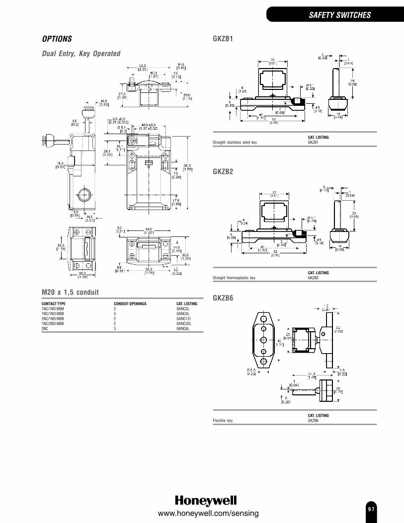
9 7www.honeywell.com/sensing
SAFETY SWITCHES
OPTIONS
Dual Entry, Key Operated
M20 x 1,5 conduitCONTACT TYPE CONDUIT OPENINGS CAT. LISTING1NC/1NO BBM 3 GKNC3L1NC/1NO MBB 3 GKNC4L2NC/1NO MBB 2 GKNC12l1NC/2NO MBB 2 GKNC33L2NC 3 GKNC6L
GKZB1
CAT. LISTINGStraight stainless steel key GKZB1
GKZB2
CAT. LISTINGStraight thermoplastic key GKZB2
GKZB6
CAT. LISTINGFlexible key GKZB6

9 8www.honeywell.com/sensing

9 9www.honeywell.com/sensing
SAFETY SWITCHES
CPS SeriesCable Pull SafetySwitch
CPS Series Cable Pull Safety Switches provide a readily accessible emergency stop signal. This is acost-effective means compared to using multiple emergency stop push-buttons. (Cable Pull SafetySwitches are not, however, to be used as a means of personnel safeguarding. They may be used toprevent further injury or damage to equipment when used for emergency stop signaling.)The CPS Series Cable Pull Safety switch is designed to provide emergency stop protection forexposed conveyor and assembly lines. The internal mechanism latches on both slackened cable(push) and pulled cable. This capability also enhances productivity by eliminating nuisance stops dueto variations in temperature, stretch of cable over time, and other application variables.The 1CPS is intended for use in applications where the cable span is 76 m [250 ft] or shorter. It is apotential economical solution for shorter runs or zone protection typical to automated systems. The2CPS series is intended for use in very long cable runs of 152 m [500 ft] or shorter, such as longconveyor lines found in warehouses.The CPS complies with: Low Voltage Directive 73/23/EEC, as amended by directive 93/68/EEC;Machinery Directive 98/37/EEC only as the directives relate to the components being used in a safetyfunction; IEC/EN 60947-1; IEC/EN 60947-5-1; IEC/EN 60947-5-5.Mechanical life: 1 000 000Sealing: IP67, NEMA 1, 4, 12,13Operating temperature: 1CPS -40 °C to 80 °C [-40 °F to 176 °F]
2CPS -40 °C to 80 °C [-40 °F to 176 °F]Approvals: AC15 A300
DC13 Q3001CPS UL, CSA2CPS UL, CSA
Contacts: 1CPS Silver1CPS, Low energy Gold plated2CPS Gold plate over silver
Switching options:1CPS 2CPS
1NC/1NO
2221
1413
N/A
2NC/2NO
2221
1413
2221
1413
2221
1413
2221
1413
3NC/1NO
2221
14132221
11 12 2221
14132221
11 12
4NC
12
2221
11 12
2221
11 12
2221
11 12
2221
11
2CPS contact block mounting: 1 To housing2 Removable with heavy duty
terminals
1
I
2
I
1CPS indicator Light Code: No letter No indicator providedA 24 Vdc red LEDB 120 Vac red LED
2CPS indicator Light Code: No letter No indicator providedA 24 Vdc red multi-cluster LEDB 120 Vac red multi-cluster LED

100www.honeywell.com/sensing
CPS Series (continued)
OPTIONS
Cable maintained1/2 in NPTCONTACT INDICATOR CAT. LISTING1NC/1NO None 1CPSA11NC/1NO 24 V 1CPSA1A1NC/1NO 120 V 1CPSA1B2NC/2NO None 1CPSA22NC/2NO 24 V 1CPSA2A2NC/2NO 120 V 1CPSA2B3NC/1NO None 1CPSA33NC/1NO 24 V 1CPSA3A3NC/1NO 120 V 1CPSA3B4NC None 1CPSA41NC/1NO, low energy None 1CPSA52NC/2NO, low energy None 1CPSA62NC/2NO, low energy 24 V 1CPSA6A2NC/2NO, low energy 120 V 1CPSA6B3NC/1NO, low energy None 1CPSA74NC, low energy None 1CPSA8
12,7[0.5]
117,42[4.623]
50,8[2.1]
172,72[6.8]
152,4[6.0]
81,28[3.2]
6,35[0.25]
99,06[3.9] 1C
PS
Cable P
ullS
witch
TE
NS
ION
ED
SLA
CK
RU
N
RE
SE
T
OF
F
4X Ø 7,11 Ø 0.28
88,9[3.5]
76,2[3.0]
33,02[1.3]
65,20[2.567]
56,79[2.236] 50,83
[2.001]
2X 26,67 [1.050]
3X 25,4 [1.0]
25,4 [1.00]
25,4 [1.00]
B
C D
A
A Fully extendedB Optional indicatorC Conduit thread (3 total) D Mounting pad (4 total)
1CPS
SAFETY SWITCHES
20 mmCONTACT INDICATOR CAT. LISTING1NC/1NO None 1CPSC11NC/1NO 24 V 1CPSC1A2NC/2NO None 1CPSC22NC/2NO 24 V 1CPSC2A2NC/2NO 120 V 1CPSC2B3NC/1NO None 1CPSC33NC/1NO 24 V 1CPSC3A4NC None 1CPSC41NC/1NO, low energy None 1CPSC52NC/2NO, low energy None 1CPSC62NC/2NO, low energy 24 V 1CPSC6A3NC/1NO, low energy None 1CPSC74NC, low energy None 1CPSC8

101www.honeywell.com/sensing
SAFETY SWITCHES
Cable maintained both sides1/2 in NPTCONTACT CONTACT BLOCK INDICATOR CAT. LISTING
MOUNTING2NC/2NO 1 None 2CPSA1A12NC/2NO 1 24 Vdc 2CPSA1A1A2NC/2NO 1 120 Vac 2CPSA1A1B3NC/1NO 1 None 2CPSA1B13NC/1NO 1 24 Vdc 2CPSA1B1A3NC/1NO 1 120 Vac 2CPSA1B1B2NC/2NO 2 None 2CPSA2A12NC/2NO 2 24 Vdc 2CPSA2A1A2NC/2NO 2 120 Vac 2CPSA2A1B3NC/1NO 2 None 2CPSA2B13NC/1NO 2 24 Vdc 2CPSA2B1A3NC/1NO 2 120 Vac 2CPSA2B1B
20 mmCONTACT CONTACT BLOCK INDICATOR CAT. LISTING
MOUNTING2NC/2NO 1 None 2CPSC1A12NC/2NO 1 24 Vdc 2CPSC1A1A4NC 1 24 Vdc 2CPSC1D1A
OFF
RUN
40,4(1.60)
67,8(2.63)
325,9(12.75)
152,4(6.00)
152,4(6.00)
12,7(0.50)
TE
NS
ION
ED
SLA
CK
TE
NS
ION
ED
SLA
CK
57,2(2.25)
139,7(5.50)
79,8(3.14)
92,9(3.66)
12,7(0.50)
21,1(0.75)
34,9(1.38)
104,8(4.13)
52,1(2.05)
81,3(3.20)
18,3(0.72)
2X
2X
2X 6,9(0.27)
2X 8,9(0.35)
2X 31,75 (1.25)
2X 6,9 (0.27)
3X 21,5 (0.85)
2X
OFF
RUN
244,6(9.63)
TE
NS
ION
ED
SLA
CK
TE
NS
ION
ED
SLA
CK
A
A
B
C
C
D
D
6,4(0.25)
40,5(1.60)
A Fully extended B Optional indicator
C Conduit thread (3 total)
D Mounting pad (4 total)
2CPS
No actuation right side, cable maintained left side1/2 in NPTCONTACT CONTACT BLOCK INDICATOR CAT. LISTING
MOUNTING2NC/2NO 1 None 2CPSA1A22NC/2NO 1 24 Vdc 2CPSA1A2A2NC/2NO 1 120 Vac 2CPSA1A2B3NC/1NO 1 None 2CPSA1B23NC/1NO 1 24 Vdc 2CPSA1B2A3NC/1NO 1 120 Vac 2CPSA1B2B2NC/2NO 2 None 2CPSA2A22NC/2NO 2 24 Vdc 2CPSA2A2A2NC/2NO 2 120 Vac 2CPSA2A2B
20 mmCONTACT CONTACT BLOCK INDICATOR CAT. LISTING
MOUNTING2NC/2NO 1 None 2CPSC1A22NC/2NO 1 24 Vdc 2CPSC1A2A
No actuation left side, cable maintained right side1/2 in NPTCONTACT CONTACT BLOCK INDICATOR CAT. LISTING
MOUNTING2NC/2NO 1 None 2CPSA1A32NC/2NO 1 24 Vdc 2CPSA1A3A2NC/2NO 1 120 Vac 2CPSA1A3B3NC/1NO 1 None 2CPSA1B33NC/1NO 1 24 Vdc 2CPSA1B3A3NC/1NO 1 120 Vac 2CPSA1B3B2NC/2NO 2 None 2CPSA2A32NC/2NO 2 24 Vdc 2CPSA2A3A2NC/2NO 2 120 Vac 2CPSA2A3B
20 mmCONTACT CONTACT BLOCK INDICATOR CAT. LISTING
MOUNTING2NC/2NO 1 None 2CPSC1A32NC/2NO 1 24 Vdc 2CPSC1A3A

102www.honeywell.com/sensing
CPS Series (continued)
Hardware packets (order separately)
CPS LED
31,75[1.25]
A
B
C
D
71,88 ±2,54[2.83 ±0.10]
207,01 ±1,27[8.15 ±0.05]
227,33 ±12,7[8.95 ±0.50]
11,43[0.45]
CPS Bracket
SAFETY SWITCHES
ACCESSORY CAT. LISTINGCable - 7,6 m [25 ft] length CLSZC1Cable - 15,2 m [50 ft] length CLSZC2Cable - 30,5 m [100 ft] length CLSZC3Cable - 45,7 m [150 ft] length CLSZC4Cable - 61 m [200 ft] length CLSZC5Cable - 76,2 m [250 ft] length CLSZC7(2) Thimbles CLSZTC(2) Low-profile Duplex Cable Clamps
ACCESSORY CAT. LISTING(1) Draw-bar Endspring CPSZ1S(1) J-hook Turnbuckle with Lock Nuts CPSZK1(2) Thimbles(2) Low-profile Duplex Cable Clamps(16) Sets of Cable Supports ((16) 1/4-20 Eye Bolts,(32) 1/4-20 Nuts, (32) Flat Washers, (16) Lock Washers)Multicluster LED Accessory - 24 Vdc (conduit mount) CPSLED24Multicluster LED Accessory - 120 Vdc (conduit mount) CPSLED120Mounting bracket (to be used with 1CPS or 2CPS) CPS-BRACKETJ-hook turnbuckle with lock nuts (included with 2CPS) CPSZTB

103www.honeywell.com/sensing
These listings include standard size basics, miniature and subminiatureswitches. The precision snap-action mechanisms are offered with a widevariety of actuators and operating characteristics. Basic switches are oftenideal for applications requiring compactness, light weight, accuraterepeatability and long life.They are best used for presence/absence detection where physical contactwith object is permissible. Very economical.
Basic Switches
BASIC SWITCHES
Overtravel plunger (standard)ELECTRICAL RATING TERMINATION CAT. LISTING15 A Screw BZ-2RD-A220 A Screw BA-2RB-A2
Panel mount overtravel plungerELECTRICAL RATING TERMINATION CAT. LISTING15 A Screw BZ-2RQ1-A220 A Screw BA-2RQ1-A2
BZ/BA/BM/BE Series Basic SwitchesBZ/BA/BM/BE Series standard basic switches may be used for simple orprecision on/off application needs.As well as the catalogue listings presented here, we offer other versions withhigher temperature ratings, different termination options, different electricalratings and Single Pole, Single Throw (SPST) circuitry. Refer to our Web sitefor details.Voltage: 250 VacElectrical rating: up to 25 AOperating temperature: -55 °C to 85 °C [-67 ° F to 185 °F]Termination: ScrewContact type: SilverApprovals: CE, CSA, UL, ENECSwitching options: Single pole, double throw (SPDT)
OPTIONSNote: BA/BE plunger position distance from mounting hole = 19 mm[0.75 in]
Top pin plungerApprovals: BE-2R-A4 CSA, UL
ELECTRICAL RATING TERMINATION CAT. LISTING15 A Solder BZ-R15 A Screw BZ-R-A215 A Solder BZ-R16915 A Screw BZ-2R-A225 A Screw BE-2R-A4

104www.honeywell.com/sensing
BASIC SWITCHES BASIC SWITCHES
Overtravel plunger (splash resistant)ELECTRICAL RATING TERMINATION CAT. LISTING15 A Screw BZ-2RDS-A215 A (Stainless steel spring) Screw BZ-2RDS-A2S
Overtravel roller plungerELECTRICAL RATING TERMINATION CAT. LISTING15 A Screw BZ-2RQ18-A2
Overtravel roller plunger, perpendicularELECTRICAL RATING APPROVALS CAT. LISTING15 A Screw BZ-2RQ181-A2
Straight leverELECTRICAL RATING TERMINATION LEVER RADIUS CAT. LISTING20 A Screw 63,5 mm [2.5 in] BA-2RV-A215 A Screw 63,5 mm [2.5 in] BZ-2RW80-A215 A Screw 152,4 mm [6.0 in] BZ-2RW863-A2
Roller leverELECTRICAL RATING TERMINATION LEVER RADIUS CAT. LISTING15 A Screw 26,67 mm [1.05 in] BZ-2RW822-A215 A Solder 26,67 mm [1.05 in] BZ-2RW82215 A (Splash resistant) Screw 26,67 mm [1.05 in] BZ-2RW8225551-A215 A Screw One way, 32,0 mm [1.26 in] BZ-2RW826-A215 A Screw 48,3 mm [1.9 in] BZ-2RW82-A2
BZ/BA/BM/BE Series (continued)

105www.honeywell.com/sensing
BASIC SWITCHES
DT Series Basic SwitchesDT Series standard basic switches consist of two independent single-poledouble throw circuits in one housing actuated by one actuator. The terminalsare separated by a non-conductive shield to reduce shorting.Voltage: 250 VacElectrical rating: 10 AOperating temperature: -55 °C to 85 °C [-67 ° F to 185 °F]Termination: ScrewContact type: SilverApprovals: CSA, ULSwitching options: Double pole, double throw (DPDT)
Top pin plungerELECTRICAL RATING TERMINATION CAT. LISTING10 A Screw DT-2R-A7
Basic Switch AccessoriesA range of accessories is available for BZ, BA, BM, BE and DT switches, suchas the 5PA2 terminal enclosure. For more information please contact yourlocal sales office.
TB Series Miniature Double-breakBasic SwitchesTB Series miniature double-break basic switches are basic double-breakunits that offer a means of controlling isolated circuits. Each circuit may bedriven by an independent voltage source.Voltage: 250 VacElectrical rating: 10 AOperating temperature: -55 °C to 125 °C [-67 ° F to 257 °F]Termination: SolderContact type: SilverApprovals: CSA, ULSwitching options: Single pole, double throw, double break (SPDT DB)
1 2
34
0.53
0.50 0.20
0.15
0.24
0.13
0.87 DIA HOLE IN TERMINALS (4)
PLASTIC PLUNGER
1.57
1.825 REF
0.06 MAX PRETRAVEL
0.16 R
0.46OPERATINGPOSITION 0.312 ± .003
0.365
1.25
0.101 DIA HOLE+.002- .001
0.101 +.002- .001
0.532 ± .003
0.03 0.09
0.25 0.50
0.260
0.22
0.113 ± .002 DIA
Dimensions in inches
NOTE-1 - TERMINALS 1 & 2 NORMALLY CLOSED CIRCUIT2 - TERMINALS 3 & 4 NORMALLY OPEN CIRCUIT3 - TERMINALS ARE PLATED FOR SOLDERING
Top pin plungerELECTRICAL RATING TERMINATION CAT. LISTING10 A Solder 1TB1-2

106www.honeywell.com/sensing
BASIC SWITCHES
SM and SX Series Subminiature BasicSwitches
SM and SX Series subminiature basic switches may be used for simpleor precision on/off application needs. These switches combine small sizeand light weight with ample electrical capacity, precision operation andlong life. The SX Series are small, precision, snap-action switches that areoften ideal where savings in space and weight are important.Voltage: 250 VacOperating temperature: -55 °C to 125 °C [-67 ° F to 257 °F]Termination: SolderContact type: SilverSwitching options: Single pole, double throw (SPDT)
SM SeriesApprovals: CE, CSA, ULElectrical rating: 5 A
OPTIONS
Top pin plungerApprovals: 11SM601-H4 UL, CSA
TERMINATION ELECTRICAL RATING CONTACT TYPE CAT. LISTING5 A silver 11SM1
Solder/quick connect 5 A silver 11SM601-H4
Straight leverLEVER LENGTH ELECTRICAL RATING CONTACT TYPE CAT. LISTING4,83 mm 5 A silver 111SM1
Roller leverTERMINATION ELECTRICAL RATING CONTACT TYPE CAT. LISTINGSolder/quick connect 5 A silver 111SM2-T
SX SeriesApprovals: CE, CSA, ULElectrical rating: 5 A
OPTIONS
Top pin plungerApprovals: 6SX7-T UL, CSA
CONTACTS ELECTRICAL RATING CAT. LISTINGSilver 7 A 1SX1-TSilver 3 A 11SX1-TGold 1 A 6SX7-T
Straight leverCONTACT TYPE ELECTRICAL RATING LEVER LENGTH CAT. LISTINGSilver 5 A ‘A’ 12,8 mm 311SX2-TSilver 5 A ‘A’ 24,5 mm 311SX3-T
Simulated rollerCONTACT TYPE ELECTRICAL RATING LEVER CAT. LISTINGSilver 5 A Roller 311SX5-T

107www.honeywell.com/sensing
BASIC SWITCHES
ZM, ZX, ZV and ZW Series SubminiatureBasic Switches
ZM, ZX, ZV and ZW Series subminiature basic switches are cost-effectivedevices used for simple on/off applications. These switches combine smallsize and light weight with ample electrical capability and long life. Plasticlever capability is available on the ZV Series.Electrical rating: 0.1 A, 3 A, 5 A or 10.1 AVoltage: 125/250 VacOperating temperature: 25 °C to 85 °C [-13 °F to 185 °F]Termination: Quick connect, solder, PCBContact type: Gold or silverSwitching options: SPDT
ZM SeriesApprovals: UL/CSAElectrical rating: 0.1 A, 5 A or 10.1 A
OPTIONS
TERMINATION ELECTRICAL RATING CONTACT TYPE CAT. LISTINGQuick connect 5 A silver ZM50E70A01Solder 5 A silver ZM50E10A01PCB 10.1 A silver ZM90G20A01Solder 0.1 A gold ZM10B10A01
ZX SeriesApprovals: UL/CSAElectrical rating: 0.1 A or 3 A
OPTIONS
TERMINATION ELECTRICAL RATING CONTACT TYPE CAT. LISTINGPCB 3 A silver ZX40E30A01Solder 0.1 A gold ZX10C10A01
TERMINATION ELECTRICAL RATING CONTACT TYPE CAT. LISTINGPCB 3 A silver ZX40E30C01Solder 3 A silver ZX40E10C01
2.05
é2.2
1.5
13.0
5.2
1.12
3.4
12.7
é2.05
PT
OP F
P
6.5
5.7
2.9
0.5
0.512
0.044
0.134 0.205
é0.081
0.05
9 0.08
1
é0.087
0.224
0.114
0.25
6
0.1243.15
0.2 0.2
0.504
12.8
0.2560.9
0.0355.08 5.08
6.5
0.228
0.0495.8
1.240.0160.4
0.13
83.
6
0.04
3
1.1
1.6
0.04
3
1.1
0.06
3
3.15
2.05
0.9
é2.2
1.5
12.8
6.5
5.08 5.08
1.12
12.7
5.2
0.4
5.8
3.6
é2.05
1.24
1.1
1.6
1.1
6.5OP FP
PT
2.9
5.7
0.044
0.205
0.5
0.114
0.224
0.25
60.
138 0.
043
0.04
3
0.06
3
0.016
0.049
0.228
é0.081
0.504
0.1240.2560.035
0.20.2
é0.087
0.05
9 0.08
1Top pin plunger
Straight lever
Top pin plunger

108www.honeywell.com/sensing
Simulated roller leverTERMINATION ELECTRICAL RATING CONTACT TYPE CAT. LISTINGPCB 3 A silver ZX40E30E01Solder 3 A silver ZX40E10E01
ZV SeriesApprovals: UL/ENECElectrical rating: 0.1 A, 5 A or 10.1 A
OPTIONS
TERMINATION ELECTRICAL RATING CONTACT TYPE CAT. LISTINGPCB 5 A silver ZV50E20A01Solder 5 A silver ZV50E10A01Quick connect 0.1 A gold ZV10B70A01
3.4 5.2
1.12
12.7
é2.05
2.05
é2.2
1.5
FP
OP
PT
11.8
0.465
0.5
0.044
0.2050.134
0.05
9 0.08
1
é0.087é0.081
0.114
0.224
2.9
5.7
0.25
66.
5
0.228
0.0495.8
1.240.0160.4
0.13
83.
6
0.04
3
1.1
1.6
0.04
3
1.1
0.06
3
0.1243.15
0.2 0.2
0.504
12.8
0.2560.9
0.0355.08 5.08
6.5
TERMINATION ELECTRICAL RATING CONTACT TYPE CAT. LISTINGQuick connect 5 A silver ZM50E70D01Solder 5 A silver ZM50E10D01
Straight lever
Simulated roller leverTERMINATION ELECTRICAL RATING CONTACT TYPE CAT. LISTINGQuick connect 5 A silver ZM50E70E01Solder 5 A silver ZM50E10E01
BASIC SWITCHES BASIC SWITCHES
Top pin plunger

109www.honeywell.com/sensing
Straight leverTERMINATION ELECTRICAL RATING CONTACT TYPE CAT. LISTINGSolder 5 A silver ZV50E10B01Quick connect 5 A silver ZV50E70C01
Roller leverTERMINATION ELECTRICAL RATING CONTACT TYPE CAT. LISTINGPCB 5 A silver ZV50E20F01Quick connect 5 A silver ZV50E70F01
BASIC SWITCHESBASIC SWITCHES
ZW Sealed SeriesApprovals: UL/ENECElectrical rating: 0.1 A or 5 ASealing: IP50 and IP67
OPTIONS
Top pin plungerTERMINATION ELECTRICAL RATING CONTACT TYPE CAT. LISTINGSolder 5 A silver ZW50F15AD1
Straight leverTERMINATION ELECTRICAL RATING CONTACT TYPE CAT. LISTINGSolder 0.1 A gold ZW10E15CD1
Roller leverTERMINATION ELECTRICAL RATING CONTACT TYPE CAT. LISTINGWire leads 0.1 A gold ZW10E90FW1

110www.honeywell.com/sensing
Printed circuit board (PO2)
These terminals interface with snap-on receptacles and other componentsfrom AMPMODU interconnection system.
PCB terminals are European approved when used with electrical ratings A, B,D, E, S.
V7 Series Miniature Basic SwitchesV7 Series basic switches may be used for simple or precision on/off, endof limit, presence/absence, pressure, temperature and manual operatorinterface application needs.Operating temperature:
-40 °C to 82 °C [-40 °F to 180 °F] (standard)-40 °C to 200 °C [-40 °F to 350 °F] (high temperature)
Termination: Printed circuit board (PCB)and two types of quick connect (QC)
D8, E8: 4,8 mm x 0.5 mm [0.187 in x 0.02 in]E9: 6,35 mm x 0,80 mm [0.25 in x 0.032 in]
Electrical rating Contact TypeV7-*A 5 A SilverV7-*B 11 A SilverV7-*C/W 15 A SilverV7-*D 1 A Gold alloyV7-*E 10 A SilverV7-*S 100 mA Gold alloyV7-*V 21 A Silver alloyV7-*Z 25 A Silver cadmium oxide
Approvals: CSA, UL, ENECV7-*C/W (Electrical ratings) CSA, UL
Switching options: Single pole double throw (NO and NC) (SPDT)
AVAILABLE TERMINALS
Quick Connect (QC)
0.187 in wide x 0.020 in thick. D8 terminals are European approved whenused with electrical ratings A, B, D, E or S. International approval agenciesrequire that switches with these terminals have insulated receptacles orconnector.
0.187 in wide x 0.020 in thick. E8 terminals are European approved whenused with electrical ratings A, B, D, E or S.
0.250 in wide x 0.032 in thick. E9 terminals are European approved whenused with electrical ratings A, B, D, E, S, V or Z.
ACTUATION OPTIONS
10,2.40
6,4.25
COMNC
NO
2,8.11
1,50.06
8,9.35
0,8.03
2,4.10
14,4.57
22,2.8828,81.14
3,20.1263,46.134OPT
18,2.72
(3)DIA
3,10.122OPT
2,90.114
10,3.41
DIA
20,2.80
2,8.11
2,8.11
1,0.04
2,90.114
Ø hole (3,10/.122 option)
MAX
Note: The optional mounting hole dimensions shown above are standard onV5/V7 International Series switches.
Top pin plungerCURRENT TERMINATION CAT. LISTING5 A QC (D8) V7-1A17D85 A PCB V7-1A17P0211 A QC (D8) V7-1B17D811 A QC (E9) V7-1B19E915 A QC (D8) V7-1C17D815 A QC (E9) V7-1C17E91 A QC (D8) V7-1D10D80.1 A QC (D8) V7-1S17D821 A QC (E9) V7-1V19E925 A QC (E9) V7-1Z19E9
BASIC SWITCHES BASIC SWITCHES

111www.honeywell.com/sensing
BASIC SWITCHES
V7 Series Miniature Basic Switches(continued)
Straight leverType -002ELECTRICAL RATING TERMINATION CAT. LISTING15 A QC (D8) V7-1C17D8-00215 A QC (E9) V7-1C17E9-00211 A QC (E9) V7-2B17E9-002
Straight leverType -022ELECTRICAL RATING TERMINATION CAT. LISTING5 A QC (D8) V7-1A17D8-02211 A QC (D8) V7-1B19D8-02215 A QC (D8) V7-1C17D8-0220.1 A QC (D8) V7-1S17D8-022
Type -048ELECTRICAL RATING TERMINATION CAT. LISTING11 A QC(D8) V7-1B17D8-04815 A QC(D8) V7-1C17D8-04821 A QC(E9) V7-1V19E9-04811 A QC(E9) V7-2B19E9-0480.1 A QC(D8) V7-3S17D8-04815 A (High temperature) QC(E9) V7-9W1AE9-048
Roller leverType -201ELECTRICAL RATING TERMINATION CAT. LISTING15 A QC (D8) V7-1C17D8-20115 A QC (E9) V7-1C17E9-2010.1 A QC (D8) V7-1S17D8-20111 A QC (D8) V7-2B17D8-201
Type -207ELECTRICAL RATING TERMINATION CAT. LISTING11 A QC (E9) V7-1B10E9-20715 A QC (D8) V7-1C17D8-20715 A QC (E9) V7-1C17E9-2070.1 A QC (D8) V7-1S17D8-20721 A QC (E9) V7-1V1939-2075 A QC (D8) V7-2A17D8-2071 A QC (D8) V7-7D17D8-207
Simulated roller leverType -263ELECTRICAL RATING TERMINATION CAT. LISTING11 A QC (D8) V7-1B17D8-26315 A QC (D8) V7-1C17D8-2630.1 A QC (D8) V7-1S17D8-2630.1 A QC (E9) V7-3S17E9-263

112www.honeywell.com/sensing
BASIC SWITCHES

113www.honeywell.com/sensing
Pressure SwitchesHoneywell has over 60 years of experience in the pressure switchindustry. A wide variety of pressure ranges, along with a wide choice ofmounting, package, and port configurations allows customers tochoose from standard off-the-shelf designs.
All Honeywell pressure switches feature excellent repeatability, enhancedaccuracy and reliability under varying environmental conditions. Inaddition, they feature highly consistent operating characteristics fromone sensor to the next and interchangeability without recalibration.
PRESSURE SWITCHES

114www.honeywell.com/sensing
Pressure Switches
5000 Series Extended Duty SwitchSet point range -0.5 psi to 150 psi [0.035 bar to 10.35 bar]This pressure switch was designed to stand up to extended dutyapplications. It is factory set but is capable of being field adjusted. TheKapton diaphragm is compatible with a wide variety of media with theexception of water. An optional Teflon diaphragm is available when wateris the operating media.Other options are available - SPDT, NO/NO or NC/NC circuitry and bladeor integral Packard MetriPack terminals - contact Honeywell sales officefor details.
Operating pressure:Set point range 0.5 psi to 24 psi = 150 psi
[0.0345 bar to 1.656 bar] = [10.350 bar]25 psi to 150 psi = 250 psi
[1.725 bar to 10.350 bar] = [17.237 bar]
Proof pressure: 500 psi (34.474 bar]
Burst pressure:Set point range 0.5 psi to 24 psi = 750 psi
[0.0345 bar to 1.656 bar] = [51.711 bar]25 psi to 150 psi = 1250 psi
[1.725 bar to 10.350 bar] = [86.185 bar]
Honeywell’s pressure and vacuum switches are designed for use inheavy duty equipment. They are suitable for potential applications thatare constantly subjected to harsh environments, such as chemicalsplashes, salt water or pressure spikes.The products listed are standard switches, but other circuitry andterminal options are available. Switches can be customised to customerrequirements, contact your local Honeywell sales office for moreinformation.Operating temperature: -40 °C to 122 °C [-40 °F to 250 °F]Termination: #8-32 screwsConnector: 1/8-27 NPT male threadContacts: Silver alloy, gold platedElectrical rating: Resistive 15 A, 6 Vdc
8 A, 12 Vdc4 A, 24 Vdc
Inductive 1 A, 120 Vac0.5 A, 240 Vac
Circuitry: SPST-NO (Normally open)SPST-NC (Normally closed)
Direct action blade contacts, 2 terminals
58,42(2.30)
37,34(1.47)
SPST-NOCONTACT SETTING PSI [BAR] FACTORY SET AT PSI [BAR] CAT. LISTING0.5 to 1.0 [0.0345 to 0.069] 1.0 [0.069] 786281.1 to 3.0 [0.0759 to 0.207] 2.0 [0.138] 760513.1 to 7.0 [0.2139 to 0.483] 4.0 [0.276] 765758.0 to 13.0 [0.552 to 0.897] 10.0 [0.690] 7657614.0 to 24.0 [0.996 to 1.656] 15.0 [1.035] 7605225.0 to 50.0 [1.725 to 3.450] 35.0 [2.415] 7605351.0 to 90.0 [3.519 to 6.210] 60.0 [4.140] 7605491.0 to 150.0 [6.279 to 10.350] 100.0 [6.90] 76055
SPST-NCCONTACT SETTING PSI [BAR] FACTORY SET AT PSI [BAR] CAT. LISTING0.5 to 1.0 [0.0345 to 0.069] 1.0 [0.069] 786321.1 to 3.0 [0.0759 to 0.207] 2.0 [0.138] 760613.1 to 7.0 [0.2139 to 0.483] 4.0 [0.276] 765778.0 to 13.0 [0.552 to 0.897] 10.0 [0.690] 7657814.0 to 24.0 [0.996 to 1.656] 15.0 [1.035] 7606225.0 to 50.0 [1.725 to 3.450] 35.0 [2.415] 7606351.0 to 90.0 [3.519 to 6.210] 60.0 [4.140] 7606491.0 to 150.0 [6.279 to 10.350] 100.0 [6.90] 76065
NOTEOperating Media (Pressure Switch)The pressure switch is designed to operate with air, motor oils,transmission oils, jet fuels and other similar hydrocarbon media.
PRESSURE SWITCHES

115www.honeywell.com/sensing
5000 Series Extended Duty Vacuum SwitchSet point range -1.1 in to 22.0 in Hg[27,94 mm Hg to 558,80 mm Hg]The 5000 Series Extended Duty Vacuum switch is designed for vacuumapplications. The factory setting cannot be changed or adjusted in thefield. It features a fluorosilicone rubber diaphragm that is compatible witha wide range of media.Blade terminal option is also available.
Connector 1/8-27 NPT MaleOperating vacuum: 30 in Hg [762 mm Hg]Burst pressure: 150 psi [10.35 bar]
Direct action blade contacts
58,42(2.30)
37,34(1.47)
SPST-NOCAT. LISTING
Internally grounded, 1 Terminal 788132 Terminals 77342
SPST-NCCAT. LISTING
Internally grounded, 1 Terminal 788152 Terminals 77343
5000 Series Extended Duty Piston SwitchSet point range -70 psi to 1000 psi [13.80 bar to 68.95 bar]This switch is a variation of the “standard” 5000 Series Extended dutyswitch for applications requiring a compact package size, enhanced setpoint and operating characteristics.Other options are available - SPDT, NO/NO or NC/NC circuitry and bladeterminals - contact Honeywell sales office for details.
Termination: #8-32 screws or 280 Series MetriPackConnector: 1/2-20 UNF [O-ring fitted]Operating pressure: 1000 psi [68.95 bar]Proof pressure: 2000 psi [138.00 bar]Burst pressure: 3000 psi [206.84 bar]
OPTIONS
Standard screw terminal, direct action bladecontacts
62,23(2.45)
37,34(1.47)
SPST-NOCONTACT SETTING PSI [BAR] APPROX. DIFFERENTIAL PSI [BAR] CAT. LISTING70 to 400 [13.80 to 27.60] 30 to 100 [2.07 to 6.90] 79700401 to 800 [27.67 to 55.20] 40 to 125 [2.76 to 8.625] 79704801 to 1000 [55.27 to 69.00] 50 to 180 [3.45 to 12.42] 79708
SPST-NCCONTACT SETTING PSI [BAR] APPROX. DIFFERENTIAL PSI [BAR] CAT. LISTING70 to 400 [13.80 to 27.60] 30 to 100 [2.07 to 6.90] 79702401 to 800 [27.67 to 55.20] 40 to 125 [2.76 to 8.625] 79706801 to 1000 [55.27 to 69.00] 50 to 180 [3.45 to 12.42] 79710
Metri-Pack terminal, direct action blade contacts
77,47(3.05)
37,34(1.47)SPST-NO
CONTACT SETTING PSI [BAR] APPROX. DIFFERENTIAL PSI [BAR] CAT. LISTING200 to 350 [13.80 to 24.15] 30 to 100 [2.07 to 6.90] 79718351 to 500 [24.22 to 34.50] 40 to 125 [2.76 to 8.625] 79720501 to 750 [34.57 to 51.75] 50 to 150 [3.45 to 12.42] 79722
SPST-NCCONTACT SETTING PSI [BAR] APPROX. DIFFERENTIAL PSI [BAR] CAT. LISTING200 to 350 [13.80 to 24.15] 30 to 100 [2.07 to 6.90] 79719351 to 500 [24.22 to 34.50] 40 to 125 [2.76 to 8.625] 79721501 to 750 [34.57 to 51.75] 50 to 150 [3.45 to 12.42] 79723
Mating connector - Packard Part Number 15300027
PRESSURE SWITCHES

116www.honeywell.com/sensing
PRESSURE SWITCHES
Pressure Switches -CustomisedThe pressure and vacuum switches on the following pages are custombuilt to customer specification, therefore minimum order quantities arerequired. Catalog listings are for reference only. Standard specification isshown below, but other contact, termination and connector options areavailable. Contact Honeywell for more information.Operating temperature: -40 °C to 122 °C
[-40 °F to 250 °F]Termination: 8 in (203,2 mm) wire leads - 18 gaConnector: 1/8-27 PTF SAE short male threadContacts: Gold over silverElectrical rating: Resistive 15 A, 6 Vdc
8 A, 12 Vdc4 A, 24 Vdc
Inductive 1 A, 120 Vac0.5 A, 240 Vac
Circuitry: SPST-NO (Normally open)SPST-NC (Normally closed)
SPDT (Dual circuit)
Series IIIFactory Set Variable DifferentialPressure and Vacuum SwitchesThe Series III features a snap action switch with gold contacts thatprovides hysteresis, low contact resistance, enhanced transfer time andan adjustable differential.Operating pressure: 200 psi [13.80 bar]Proof pressure: 350 psi [24.13 bar]Burst pressure: 500 psi [34.49 bar]
63,50(2.5)
42,93(1.69)
OPTIONS
Pressure switch, snap action contactsSet point range - 2 psi to 70 psi [0.138 bar to 4.83 bar]SET POINT RANGE PSI [BAR] DIFFERENTIAL PSI [BAR] REF. LISTING2 to 4 [0.138 to 0.276] 1 to 1.5 [0.069 to 0.103] 1200004 to 12 [0.276 to 0.828] 2 to 6 [0.138 to 0.414] 12000112 to 24 [0.828 to 1.656] 8 to 12 [0.552 to 0.828] 12000224 to 40 [1.656 to 2.760] 10 to 18 [0.690 to 1.242] 12000340 to 70 [2.760 to 4.830] 15 to 20 [1.035 to 1.380] 120004
Vacuum switch, snap action contactsSet point range -1.1 in Hg to 22 in Hg [27,94 mm Hg to 558,8 mm Hg]SET POINT RANGE IN HG [MM HG] DIFFERENTIAL IN HG [MM HG] REF. LISTING15 in H2O to 36 in H2O [28,025 to 67,259] 4 in H2O to 12 in H2O [7,473 to 22,420] 1200052 to 6 [50,8 to 152,4] 0.4 to 1 [10,16 to 25,40] 1200066 to 12 [152,4 to 304,8] 0.4 to 1 [10,16 to 25,4] 12000712 to 22 [304,8 to 558,8] 0.6 to 1.5 [15,24 to 38,1] 120008
5000 Series Ultra Duty SwitchSet point range -10 psi to 400 psi [0.69 bar to 27.60 bar]The 5000 Series Ultra Duty pressure switch is designed for highpressure/low set point applications that can experience sudden pressurespikes and high system pressures. Screw machined and heat treatedcomponents along with a reduced effective area in the pressure cavityallow improved performance over the standard extended duty 5000Series.Other options are available - Dual Circuit (SPDT) configuration and bladeor integral Packard MetriPack terminals - contact Honeywell sales officefor details.
Connector 1/8-27 NPT MaleOperating pressure: 500 psi [34.50 bar]Proof pressure: 2000 psi [138.00 bar]Burst pressure: 4000 psi [276.00 bar]
Direct action blade contacts, 2 terminals
58,42(2.30)
37,34(1.47)
SPST-NOCONTACT SETTING PSI (BAR] FACTORY SET AT PSI [BAR] CAT. LISTING10 to 35 [0.69 to 2.41] 20 [1.38] 8329835 to 75 [2.41 to 5.17] 60 [4.14] 8330175 to 150 [5.17 to 10.35] 100 [6.90] 83304150 to 250 [10.35 to 17.25] 200 [13.89] 83307250 to 400 [17.25 to 27.6] 300 [20.70] 83310
SPST-NCCONTACT SETTING PSI [BAR] FACTORY SET AT PSI [BAR] CAT. LISTING10 to 35 [0.69 to 2.41] 20 [1.38] 8329935 to 75 [2.41 to 5.17] 60 [4.14] 8330275 to 150 [5.17 to 10.35] 100 [6.90] 83305150 to 250 [10.35 to 17.25] 200 [13.89] 83308250 to 400 [17.25 to 27.6] 300 [20.70] 83311

117www.honeywell.com/sensing
PRESSURE SWITCHES
Pressure Switches - Customised(continued)
Series VHigh Pressure, Environmentally Sealed,Extreme Duty SwitchesSet point range -35 psi to 3000 psi [2.415 bar to 206.84 bar]The Series V features a snap action switch with gold-plated contacts thatprovides hysteresis, low contact resistance, enhanced transfer time andan adjustable differential.
OPTIONS
Diaphragm switch, snap action contactsSet point range -35 psi to 300 psi [2.415 bar to 20.70 bar]The diaphragm material is fluorosilicone and is compatible with air,motor and transmission oil and other hydrocarbon media.
Connector: 1/8-27 PTFOperating pressure: 300 psi [20.70 bar]Proof pressure: 500 psi [34.47 bar]Burst pressure: 2000 psi [138.00 bar]
81,03(3.19)
30.15(1.187)
SET POINT RANGE PSI [BAR] DIFFERENTIAL PSI [BAR] REF. LISTING35 to 50 [2.415 to 3.45] 10 to 15 [0.690 to 1.035] 2690050 to 100 [3.45 to 6.90] 10 to 15 [0.690 to 1.035] 26901100 to 200 [6.90 to 13.80] 10 to 15 [0.690 to 1.035] 26902200 to 300 [13.80 to 20.70] 10 to 20 [0.690 to 1.380] 26903
Piston seal switch, snap action contactsSet point range -100 psi to 3000 psi [6.90 bar to 206.84 bar]The piston seal is nitrile and is compatible with motor and transmissionoil and other hydrocarbon media. An optional seal is available for usewith brake fluid.
Connector: 3/4-16 UNF (O-ring fitting)Operating pressure: 3000 psi [206.84 bar]Proof pressure: 5000 psi [345.00 bar]Burst pressure: 10000 psi [690.00 bar]
84,84(3.34)
30.15(1.187)
SET POINT RANGE PSI [BAR] DIFFERENTIAL PSI [BAR] REF. LISTING100 to 150 [6.90 to 10.35] 35 to 50 [2.415 to 3.450] 26904150 to 250 [10.35 to 17.25] 50 to 75 [3.450 to 5.175] 26905250 to 500 [17.25 to 34.50] 75 to 100 [5.175 to 6.90] 26906500 to 750 [34.50 to 48.30] 100 to 150 [6.90 to 10.35] 26907750 to 1000 [48.30 to 69.00] 150 to 300 [10.35 to 20.70] 269081000 to 1250 [69.00 to 86.25] 175 to 350 [12.075 to 24.15] 269091250 to 1500 [86.25 to 103.50] 175 to 360 [12.075 to 24.84] 269101500 to 1750 [103.50 to 120.75] 220 to 370 [15.18 to 25.53] 269111750 to 2000 [120.75 to 138.00] 230 to 380 [15.87 to 26.22] 269122000 to 2250 [138.00 to 155.25] 250 to 390 [17.25 to 26.91] 269132250 to 2500 [155.25 to 172.50] 355 to 400 [24.495 to 27.60] 269142500 to 2750 [172.50 to 189.75] 370 to 420 [25.53 to 28.98] 269152750 to 3000 [189.75 to 206.84] 385 to 450 [26.565 to 31.05] 26916

118www.honeywell.com/sensing

119www.honeywell.com/sensing
Environment Sealed,Hermetically Sealedand Manual switches
ENVIRONMENT SEALED SWITCHES
Most of the products in this section have onething in common - they are sealed to withstandharsh environments.
You will find them in such diverse places aslanding gears, flaps, cargo doors and cockpitpanels. Environmentally sealed products alsosatisfy needs in many other potentialapplications. Some examples are agriculture,transportation, construction, marine, ordnanceand command and control equipment.
Our commitment to quality products beginswith the design of the products. Marketing,design and manufacturing engineeringpersonnel review the customer specificationsand translate them into design andmanufacturing instructions. Every productHoneywell manufactures, be it an aerospace,industrial or commercial design, follows asingle, uniform system of quality assurance.This helps ensure the same high level ofreliability in all our products. Our aim is to buildin quality.
We have evaluation test labs that can subjectour designs to most every test andenvironmental condition known to exist in ourworld or in outer space. Test equipmentincludes - electrical and mechanical life cyclingdevices, high-low temperature chambers,hydrostatic pressure chambers, impact shockmachines, vibration equipment, centrifugalacceleration equipment, humidity and saltspray chambers, and dielectric strength testingequipment.
To ensure you have the latest information onour product offering, contact Honeywell.
Switch load/lifeSwitch life depends on such criteria as electricalload, environment, switch mechanism and otherfactors peculiar to the application. As electrical loadincreases, switch life decreases. For militaryqualification testing 25,000 operations electrical lifeat rated load (maximum recommended load) is theminimum operations required. In most casesswitch life exceeds 25,000 operations whenoperated at electrical loads less than rated load.Below one amp, the electrical life approaches themechanical life of the switch. If your applicationrequires more than 25,000 cycles and yourelectrical load is less than rated load, please contactHoneywell for application assistance.
Sealed basic switches and switchassembliesBasic switches are either environment sealed or hermetically sealed. The environment sealedbasics have a watertight seal and most meet military specifications. Limit switches are environmentsealed or hermetically sealed and some are suitable for high temperature applications. Mostswitches meet appropriate military requirements. Environment sealed limit switches come in achoice of sizes and are offered for military aerospace and commercial aircraft applications.Hermetically sealed switches withstand temperatures up to 125 °C [257 °F], and high temperaturehermetically sealed switches will operate in temperatures up to 334 °F [615 °F].
Manual control switchesStandard size and some miniature toggle switches have bushing seals and are military qualified. Rockerswitches also have a bushing seal. Rockers are easy to remove and are available in a variety of colours.Magnetically held toggle switches contain a holding coil to maintain the toggle in the operated position.They have environment sealing, and most are military qualified.

120www.honeywell.com/sensing
Military specificationsprocurement information
How to increase your effectivenessin using specification MIL-PRF-8805The following information is intended to increaseyour effectiveness in using the SpecificationMIL-PRF-8805, minimize your costs andreduce delivery time for switches procured tothe Specification.
Standard items(shown on QPL 8805)HONEYWELL suggests the following statement beused when ordering items appearing on QPL8805:“Honeywell” catalog listing No. listed on QPL8805 as No. .”Should additional requirements be needed forapplication of the switch in its end use, theyshould be specifically stated as part of theordering information.
Non-standard items(not shown on QPL 8805)Honeywell suggests the following statement beused when ordering items which do not appear onQPL 8805:“Switch drawing No. shall meet the followingperformance requirements of MIL-PRF-8805.”The above statement to be supplemented bythe performance requirements which youconsider applicable.
Why the suggested statements willminimize cost and delivery of non-standard itemsMilitary Specification MIL-PRF-8805 requires acomplete qualification test of non-standard items(unless you specifically call out the performancerequirements which you consider applicable toyour switch application). Complete qualificationis costly and will delay shipment of switches. Byspecifying all those requirements which youconsider applicable you can minimize both yourcost and delivery flow time. General statements,such as “switch must meet requirements ofMIL-PRF-8805”, require complete MIL-PRF-8805 qualification tests.Honeywell believes that you, the user, knowbest the specific requirements of yourapplication. These requirements may be moreor less severe than those reflected by the testparameters of MIL-PRF-8805. In the interest ofsupplying switches which will meet yourrequirements with a minimum of expense anddelay, we suggest use of the applicablestatement provided for Standard (QPL) itemsand Non-Standard items (not on QPL).Honeywell solicits submittal of your proposalprints for review and comment. This reviewmay result in savings of time and cost for you.
Basic switchesoperating characteristics
Electromechanical switchesDefinitions below explain the meaning of operating characteristics. Characteristics shown in tablesthroughout this catalog were chosen as most significant. They are taken at normal room temperatureand humidity. These characteristics may vary as temperature and humidity conditions differ.Sketches show how characteristics are measured for in-line plunger actuation.Linear dimensions for in-line actuation are from top of plunger to a reference line, usually thecenter of the mounting holes.Differential Travel (D.T.)—Plunger or actuator travel from point where contacts “snap-over” topoint where they “snapback.”Free Position (F.P.)—Position of switch plunger or actuator when no external force is applied(other than gravity).Full Overtravel Force—Force required to attain full overtravel of actuator.Operating Position (O.P.)—Position of switch plunger or actuator at which point contacts snapfrom normal to operated position. Note that in the case of flexible or adjustable actuators, theoperating position is measured from the end of the lever or its maximum length. Location ofoperating position measurement shown on mounting dimension drawings.Operating Force (O.F.)—Amount of force applied to switch plunger or actuator to cause contact“snap-over.” Note in the case of adjustable actuators, the force is measured from the maximumlength position of the lever.Overtravel (O.T.)—Plunger or actuator travel safely available beyond operating position.Pretravel (P.T.)—Distance or angle traveled in moving plunger or actuator from free position tooperating position.Release Force (R.F.)—Amount of force still applied to switch plunger or actuator at moment contactssnap from operated position to unoperated position.Total Travel (T.T.)—Distance from actuator free position to overtravel limit position.
In-line plunger actuation
Toggle switch locking configurationsToggle switches are available with the following locking configurations -
A B D E F G H
Locked In Locked Out OfCenter and Locked Out Locked In Locked In Center And
Locked In Extreme Position Of Center Locked In Extreme Position Extreme Position Extreme PositionThree Positions (Keyway Side) Position Center Position (Opposite Keyway) (Keyway Side) (Keyway Side)
J K L M N P
Locked Out Of Locked In Locked Out Of Locked Out OfCenter And Center And Locked Out Of And Into Locked Out Of And Into
Extreme Position Extreme Position Extreme Position Extreme Position Extreme Position Extreme Position(Opposite Keyway) (Opposite Keyway) (Keyway Side) (Opposite Keyway) (Opposite Keyway) (Keyway Side)
SEALED SWITCHES

121www.honeywell.com/sensing
SEALED SWITCHES
SE and XE SeriesEnvironmentally SealedBasic Switches
SE and XE Series switches are the smallest, environment sealed switchesoffered by Honeywell. They enclose basic switches within a corrosion-resistant aluminum housing to seal precision switch contacts fromcontamination. SE switches include a SM basic switch; XE switches includethe smaller SX basic switch.Housing material: AluminiumSealing: Watertight seal per MIL-PRF-8805, symbol 3Termination: 305,0 mm [1 ft] leadwire or Solder (turret)Contacts: Silver
Switching options:SPDT Single Pole, Double Throw
SPNC Single Pole, Normally Closed
SPNO Single Pole, Normally Open
Electrical ratings: A 5 A res., 3 A ind., (sea level),5 A res., 2.5 A ind., [50000 ft], 28 Vdc
5 A res., 5 A ind., 125 or 250 Vac, 60 Hz
B UL/CSA rating - 5A, 250 Vac, 60 Hz
C 7 A res., 4 A ind., (sea level)7 A res., 2.5 A ind., [50000 ft], 28 Vdc
7 A res., 4 A ind., (sea level)115 Vac, 400 Hz
D UL Rating - 7 A, 250 Vac, 60 Hz
E 7 A res., 4 A ind., (sea level)7 A res., 2.5 A ind., [50000 ft], 28 Vdc
F 1 A res., 0.5 A ind., 28 Vdc

122www.honeywell.com/sensing
SEALED SWITCHES
SE Series
Package size: 19,05 mm H x 8,64 mm W x 22,35 mm L[0.75 in H x 0.34 in W x 0.88 in L]
Operating temperature:Standard -53 °C to 105 °C [-65 °F to 221 °F]
Low -26 °C to 80 °C [-15 °F to 185 °F]Approvals: UL, CSA (4SE1 only)Operating force max. (OF):
Standard 1,39 N to 4,73 N [5.0 oz to 17.0 oz]Low 1,11 N to 2,22 N [4.0 oz to 8.0 oz]High 1,39 N to 5,28 N [5.0 oz to 19.0 oz]
Pretravel max. (PT): 1,27 mm [0.050 in]Overtravel min. (OT): 0,08 mm [0.003 in]Differential travel max. (DT): 0,10 mm [0.004 in]
Top pin plunger
OPTIONS
SPDT Single Pole, Double ThrowLeadwire termination
FEATURES ELECTRICAL RATING CAT. LISTINGA 1SE1
Gold contacts F 1SE7Gold bifurcated contacts F 1SE401UL/CSA listing/leadwires B 4SE1Fluorosilicone seal/Low temperature A 5SE1Low OF A 7SE1
Solder (Turret) termination
FEATURES ELECTRICAL RATING CAT. LISTINGA 1SE1-T
Gold contacts F 1SE61-THigh OF A 12SE4-T
SPNC Single Pole, Normally ClosedLeadwire termination
ELECTRICAL RATING CAT. LISTINGA 1SE2
SPNO Single Pole, Normally OpenLeadwire termination
ELECTRICAL RATING CAT. LISTINGA 1SE3
Solder (Turret)
Leadwire

123www.honeywell.com/sensing
SEALED SWITCHES
SE Series Auxiliary actuators(Switches must be ordered separately)
Operating force max. (OF): 3,34 N [12 oz]Pretravel max. (PT): 3,81 mm [0.150 in]Overtravel min. (OT): 0,38 mm [0.015 in]Differential travel max. (DT): 0,64 mm [0.025 in]
Straight leaf
CAT. LISTINGJE-1
Roller leaf , perpendicular
CAT. LISTINGJE-4
Roller leaf
CAT. LISTINGJE-5

124www.honeywell.com/sensing
SEALED SWITCHES
XE Series
Package size: 19,05 mm H x 8,13 mm W x 15,75 mm L[0.75 in H x 0.32 in W x 0.62 in L]
Operating temperature:Standard -55 °C to 85 °C [-67 °F to 185 °F]
High -53 °C to 149 °C [-65 °F to 300 °F]Low -26 °C to 85 °C [-15 °F to 185 °F]
Approvals: UL, CSA (4XE1 only)Operating force max. (OF):
Standard 1,39 N to 4,73 N [5.0 oz to 17.0 oz]Low 2,50 N [9 oz]
Pretravel max. (PT):Standard 1,27 mm [0.05 in]
Low 0,76 mm [0.03 in]Overtravel min. (OT): 0,10 mm [0.004 in]Differential travel max. (DT): 0,13 mm [0.005 in]
Top pin plunger
OPTIONS
SPDT Single Pole, Double ThrowLeadwire termination
FEATURES ELECTRICAL MILITARY PART CAT. LISTINGRATING NUMBERC MS27994-1 1XE1C MS27994-4 1XE201
Gold contacts F MS27994-5 1XE301Gold bifurcated contacts/high temperature/1524 mm [6 ft]leadwire length F 1XE401-6Low OF/Low PT/high temperature E 14XE1UL/CSA listing/leadwires D 4XE1Fluorosilicone seal/low temperature C 5XE1
Solder (Turret) termination
FEATURES ELECTRICAL MILITARY PART CAT. LISTINGRATING NUMBERA MS27994-3 1XE1-T
Gold bifurcated contacts/high temperature F 1XE401-TGold contacts F 1XE99-TLow OF/Low PT/high temperature E 14XE1-T
SPNO Single Pole, Normally OpenLeadwire termination
ELECTRICAL MILITARY PART CAT. LISTINGRATING NUMBERC 1XE3
Solder (Turret)
Leadwire
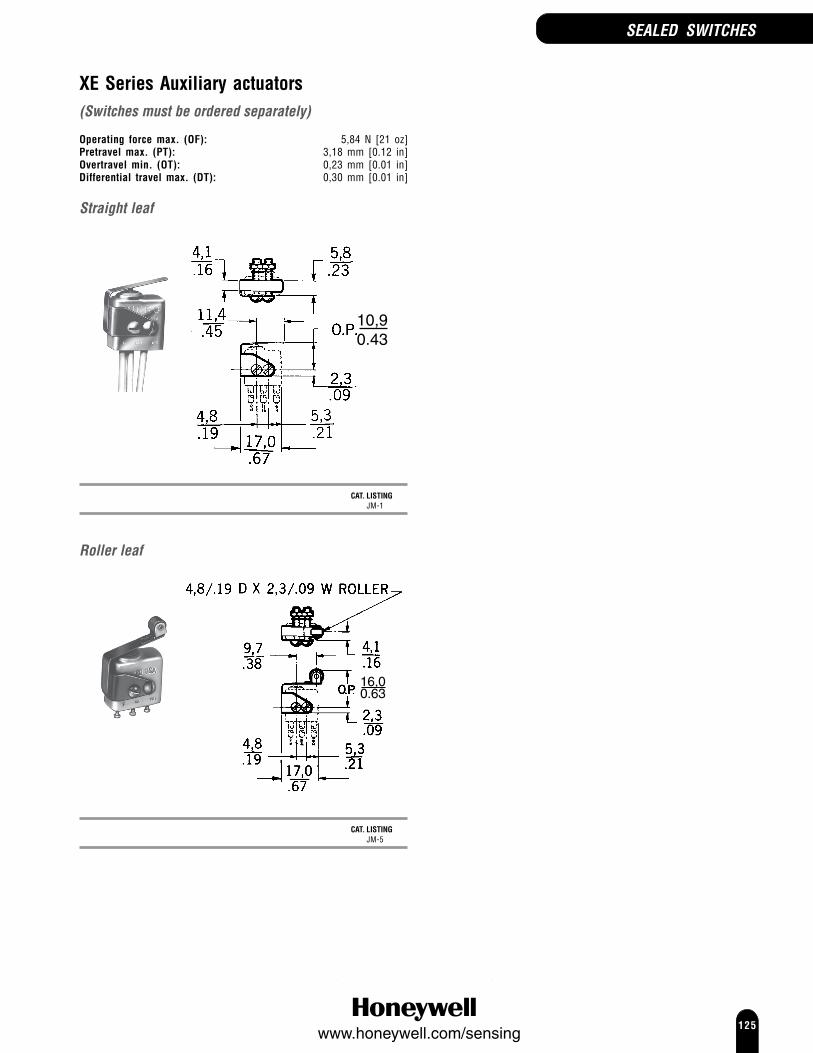
125www.honeywell.com/sensing
SEALED SWITCHES
XE Series Auxiliary actuators(Switches must be ordered separately)
Operating force max. (OF): 5,84 N [21 oz]Pretravel max. (PT): 3,18 mm [0.12 in]Overtravel min. (OT): 0,23 mm [0.01 in]Differential travel max. (DT): 0,30 mm [0.01 in]
Straight leaf
10,90.43
CAT. LISTINGJM-1
Roller leaf
16,00.63
CAT. LISTINGJM-5

126www.honeywell.com/sensing
HM SeriesMiniature, HermeticallySealed, Basic SwitchesHM Series hermetically sealed basic switches contain contacts in a sealedchamber. A gas-tight seal is maintained while transmitting force and motionto the switch mechanism through a metal diaphragm.This series is not generally recommended for 115 Vac, 60 Hz. If you have a60 Hz application in the mA range, or applications that require the switch tofunction electrically during exposure to sub-freezing temperatures, contactHoneywell for special design variations that are available.Package size: 18,29 mm H x 6,35 mm W x 22,35 L
(0.72 in H x 0.25 in W x 0.88 in L]Housing material: Stainless SteelSealing: Hermetic MIL-PRF-8805, design symbol 5Termination: Solder or leadwireOperating force max. (OF): 1,95 N [7.00 oz]Pretravel max. (PT): 0,76 mm [0.03 in]Overtravel min. (OT): 0,08 mm [0.003 in]Differential travel max. (DT): 0,15 mm [0. 006 in]Switching options:SPDT Single Pole, Double Throw
Electrical ratings:A 1 A res., 0.25 A ind., (sea level or 70000 ft), 28 Vdc
B 4 A res., 2 A ind., (sea level), 28 Vdc
C 0.5 A res., 0.25 A ind., (sea level or 70000 ft), 28 Vdc
D 3 A res., 1 A ind. (sea level or 70000 ft), 28 Vdc1 A res., or ind. (sea level), 115 Vac, 400 Hz
E 0.1 A res., 0.1 A ind., 28 Vdc
Temperature range:1 -65 °C to 121 °C [-85 °F to 257 °F]
2 -65 °C to 176 °C [-85 °F to 350 °F]
3 -65 °C to 260 °C [-85 °F to 500 °F]
4 -184 °C to 121°C [-300 °F to 250 °F]
5 -184 °C to 260 °C [-300 °F to 500 °F]
Integral lever
OPTIONS
Leadwire termination
CABLE CONTACT TEMPERATURE ELECTRICAL MILITARY PART CAT. LISTINGLENGTH MATERIAL RANGE RATING NUMBER152,4 mm [6 in] Gold 2 E 114HM1-2 [1]
304,8 mm [1 ft] Gold Bifurcated 3 C 20HM1-1304,8 mm [1 ft] Silver 1 B MS27216-2 2HM19-11524,0 mm [5 ft] Silver 1 B MS27216-4 2HM19-5
[1] Mechanical life 100 000 operations
Leadwire, potted
CABLE CONTACT TEMPERATURE ELECTRICAL MILITARY PART CAT. LISTINGLENGTH MATERIAL RANGE RATING NUMBER304,8 mm [1 ft] Silver cadmium 3 B 6HM1-1
oxide
SEALED SWITCHES
Application notes1 Honeywell does not recommend the use of silver cadmium oxide switch
contacts in non-arcing loads. Non-arcing loads are generally loads lessthan 12 V and/or 0.5 A. Catalog listings in the 5, 6, 15, and16HM Seriesuse silver cadmium oxide contacts. If you have specific questions,contact Honeywell.
2 For applications involving non-arcing loads, catalog listings in the 9, 10,19 and 20HM Series are recommended.

127www.honeywell.com/sensing
HM Series, Integral lever (continued)
Solder termination
CONTACT TEMPERATURE ELECTRICAL MILITARY PART CAT. LISTINGMATERIAL RANGE RATING NUMBERSilver 4 D MS27216-5 11HM1Gold 4 A 13HM1Gold Bifurcated 5 C 19HM1Gold Bifurcated 5 C 19HM4 [2]
Gold Bifurcated 4 C MS27216-6 9HM1Gold Bifurcated 4 C 109HM1 [3]
[2] Only metal and glass material exposed external to switch (i.e. vacuum application consideration)
[3] Mechanical life 100 000 operations
Electrical life 25 000 operations at full rated load
Solder, weld
8,4.33
CONTACT TEMPERATURE ELECTRICAL MILITARY PART CAT. LISTINGMATERIAL RANGE RATING NUMBERSilver cadmium oxide 3 D 15HM2Silver cadmium oxide 5 D 15HM5 [2]
HM Series Auxiliary actuators
(Switches must be ordered separately)
Operating force max. (OF): 2,50 N [9.0 oz]Overtravel min. (OT): 0,76 mm [0.030 in]Differential travel max. (DT): 0,76 mm [0. 030 in]
Straight leaf
CAT. LISTINGJS-254
Roller leaf
CAT. LISTINGJS-151
Mounting plateA force spreading plate is recommended to reduce the risk of productdamage due to excessive mounting force.
12,19(0.48)
15,75(0.062)
9,525(0.375)
0,79(0.031)
Ø 2 x 2,39(0.094)
CAT. LISTING19PA137-HM
NoticeTorque on #2 mounting screws must be restricted to0,16 N m [1.5 in lb] max. to prevent switch damage. Theforce spreading mounting plate 19PA137-HM will allow upto 0,28 N m [2.5 in lb] of mounting torque.
SEALED SWITCHES

128www.honeywell.com/sensing
HS SeriesHermetically Sealed BasicSwitches
HS Series Hermetically Sealed Switches are designed for potentialapplications where maximum electrical rating and maximum sealing areessential, and where size and weight requirements are less critical. Theseswitches are side-mounted through mounting holes located outside thesealed switching chamber.
SEALED SWITCHES
Package size: Standard 25,4 mm H x 17,8 mm W x 50,8 mm L[1.0 in H x 0.7 in W x 2.0 in L]
Housing material: Stainless Steel, phenolicSealing: Hermetic MIL-S-8805, design symbol 5Operating temperature: Standard -55 °C to 125 °C
[-67 °F to 250 °F]High -55 °C to 149 °C
[-67 °F to 300 °F]Approvals: UL, CSA (screw terminals)Termination: Screw or leadwireOperating force max. (OF): 2,78 N to 6,12 N [10 oz to 22 oz]Pretravel max. (PT): 1,65 mm [0.065 in]Overtravel min. (OT): 0,25 mm [0.010 in]Differential travel max. (DT): 0,51 mm [0.020 in]Contacts: SilverSwitching options:SPDT Single Pole, Double Throw
Electrical ratings: A 25 A res., 8 A ind., 28 Vdc1 A res., 1 A ind, 115 Vac
UL-CSA rating - 1 A, 125 Vac
B 15 A res., 8 A ind., 28 Vdc0.5 A res., 1A ind., 125 Vac
C 15 A res., 8 A ind., 28 Vdc0.5 A res., 1A ind., 125 Vac
UL-CSA rating - 1 A, 125 Vac
D 25 A res., 8 A ind., 28 Vdc0.5 A res., 1 A ind., 125 VacUL-CSA rating - 1A, 125 Vac
OPTIONS
Top roller lever
Screw termination
ELECTRICAL MILITARY PART CAT. LISTINGRATING NUMBERA 1HS3

129www.honeywell.com/sensing
SEALED SWITCHES
Integral lever
Screw termination
StandardELECTRICAL MILITARY PART CAT. LISTINGRATING NUMBERA MS25011-1 1HS1D 101HS1
High TemperatureOperating force (OF): 2,78 N to 8,34 N [10 oz to 30 oz]
ELECTRICAL MILITARY PART CAT. LISTINGRATING NUMBERC 102HS1
Increased operating forceOperating force (OF): 6,12 N to 7,78 N [22 oz to 28 oz]Pretravel max. (PT): 2,16 mm [0.85 in]
ELECTRICAL MILITARY PART CAT. LISTINGRATING NUMBERA MS25011-4 1HS6
Leaf - added overtravel
Operating force (OF): 1,11 N to 5,56 N [4 oz to 20 oz]Pretravel max. (PT): N/AOvertravel max. (OT): 1,57 mm [0.062 in]Differential travel max. (DT): 2,54 mm [0.100 in]
ELECTRICAL MILITARY PART CAT. LISTINGRATING NUMBERA 1HS41
Leadwire termination
ELECTRICAL MILITARY PART CAT. LISTINGRATING NUMBERB 4HS4-118

130www.honeywell.com/sensing
SEALED SWITCHES
HT SeriesHigh Temperature BasicSwitches
HT Series High Temperature Switches are designed to withstandtemperatures up to +538 °C [+1000 °F]. The switching element ismounted on a ceramic base with a stainless steel enclosure.Note: HT Series switches are not classified as sealed switches.
Package size: Standard 31,75 mm H x 17,78 mm W x 49,78 mm L[1.25 in H x 0.70 in W x 1.96 in L]
Housing material: Ceramic/Stainless SteelSealing: NoOperating temperature: 538 °C [1000 °F]Approvals: UL, CSATermination: ScrewElectrical rating: 3 A, 1/10 HP, 125 Vac
2 A, 1/6 HP, 250 VacSwitching options:SPDT Single Pole, Double Throw
OPTIONS
Top pin plunger, panel mount
Operating force max. (OF): 2,78 N to 5,6 N [10 oz to 20 oz]Pretravel max. (PT): 1,65 mm [0.06 in]Overtravel min. (OT): 4,78 mm [0.19 in]Differential travel max. (DT): 0,25 mm [0.01 in]
CAT. LISTING1HT1
Top pin plunger, side mount
Operating force max. (OF): 2,78 N to 5,6 N [10 oz to 20 oz]Pretravel max. (PT): 1,27 mm [0.05 in]Overtravel min. (OT): 0,25 mm [0.01 in]Differential travel max. (DT): 0,25 mm [0.01 in]
CAT. LISTING2HT1
Top roller plunger, panel mount
Operating force max. (OF): 8.34 N [30 oz]Pretravel max. (PT): 1,65 mm [0.06 in]Overtravel min. (OT): 4,78 mm [0.19 in]Differential travel max. (DT): 0,254 mm [0.01 in]
CAT. LISTING3HT1

131www.honeywell.com/sensing
EN SeriesEnvironment SealedLimit Switches
The EN Series Environment-sealed Limit Switch has resilient sealing as defined in MIL-S-8805,Symbol 4. In addition to the standard versions, miniature housing constructions may be availablewith similar actuator styles. The miniature versions may meet the demand for smaller size andlighter weight without sacrificing performance or electrical capacity. The miniature version housingis 7,92 mm [0.312 in] smaller in diameter and weighs 14,2 g [0.5 oz] less than the standardversion.Housing material: Stainless SteelSealing: Hermetic MIL-PRF-8805, design symbol 4Operating temperature: -54 °C to 85 °C [-65 °F to 185 °F]Termination: 1,829 m [6 ft] Leadwire (#18 and #20)
Receptacle (bottom or side)Contacts: SilverSwitching options:DPDT Double Pole, Double Throw
1
4
2
35
6
4PDT 4 Pole, Double Throw
1
4
2
35
6
7
10
8
911
12
1 CKT, DB Single Pole, Double Throw, Double Break
3
2
4
1
2 CKT, DB Double Pole, Double Throw, Double Break
1
4
2
35
8
6
7
SEALED SWITCHES
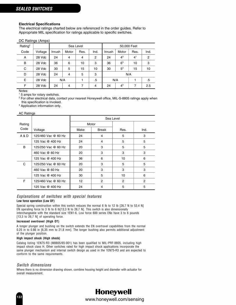
132www.honeywell.com/sensing
SEALED SWITCHES
Explanations of switches with special featuresLow force operation (Low OF)Special spring construction within this switch reduces the normal 6 lb to 12 lb [26,7 N to 53,4 N]EN operating force to 3 lb to 6 lb[13,3 N to 26,7 N]. This switch is also dimensionallyinterchangeable with the standard size 1EN1-6. Low force 600 series ENs have 3 to 6 pounds[13,3 to 26,7 N] of operating force.Increased overtravel (High OT)A longer plunger and bushing on the switch extends the EN overtravel capabilities from the normal0.25 in to 0.86 in [6,35 mm to 21,8 mm]. The longer bushing also permits additional adjustmentof the plunger position.High impact shock (High shock)Catalog listing 1EN75-R3 (M8805/65-001) has been qualified to MIL-PRF-8805, including highimpact shock class H. Other switches rated for high impact shock applications incorporate thesame plunger mechanism and internal switch design as used in the 1EN75-R3 and are expected toconform to the same requirements.
Switch dimensionsWhere there is no dimension drawing shown, combine housing height and diameter with actuator foroverall measurement.
Electrical Specifications The electrical ratings charted below are referenced in the order guides. Refer to Appropriate MIL specification for ratings applicable to specific switches. DC Ratings (Amps)
Rating2 Sea Level 50,000 Feet
Code Voltage Inrush Motor Res. Ind. Inrush Motor Res. Ind.
A 28 Vdc 24 4 4 2 24 43 41 2
B 28 Vdc 36 6 10 3 36 63 10 3
C 28 Vdc 30 5 15 10 30 53 15 10
D 28 Vdc 24 4 5 3 N/A
E 28 Vdc N/A 1 .5 N/A 1 .5
F 28 Vdc 24 4 7 4 24 43 7 2.5
Notes: 1 5 amps for rotary switches. 2 For other electrical data, contact your nearest Honeywell office, MIL-S-8805 ratings apply when this specification is invoked. 3 Application information only. AC Ratings
Sea Level
Motor Rating Code Voltage Make Break Res. Ind.
125/460 Vac @ 60 Hz 24 4 5 3 A & D
125 Vac @ 400 Hz 24 4 5 5
125/250 Vac @ 60 Hz 20 3 5 5
460 Vac @ 60 Hz 20 3 3 3
B
125 Vac @ 400 Hz 36 6 10 6
125/250 Vac @ 60 Hz 20 3 5 5
460 Vac @ 60 Hz 20 3 3 3
C
125 Vac @ 400 Hz 30 5 10 6
125/460 Vac @ 60 Hz 12 2 2 2 F
125 Vac @ 400 Hz 24 4 5 5

133www.honeywell.com/sensing
EN SeriesStandard switchesOperating characteristics (except where specified otherwise )Operating force max. (OF): 26,69 N to 53,38 N [6 lb to 12 lb]
Low 13,3 N to 26,7 N [3 lb to 6 lb]Pretravel max. (PT): 1,02 mm [0.04 in]Overtravel min. (OT): 6,35 mm [0.25 in]
High 12,7 mm [0.50 in]Differential travel max. (DT): 0,51 mm [0.020 in]
OPTIONS
Top pin plungers
Leadwire #20 wire gage
1EN1-6/1EN231-6/1EN51-6
72,42.85
or
or
57,42.26
45,71.8
1EN61-6/1EN412-3
CIRCUITRY ELECTRICAL MILITARY PART CAT. LISTINGRATING NUMBER
DPDT A MS24331-1 1EN1-6High shock DPDT A 1EN231-6Low OF DPDT A 1EN51-6High OT DPDT A 1EN61-6Gold contacts DPDT E 1EN412-3
Leadwire #18 wire gage
Housingheight
HousingØ
2EN/3EN/4EN Series
Pretravel Differential travel Housingmax. (PT) max. (DT) Height Diameter
2EN 1,27 mm 0,89 mm 38,1 mm 38,1 mm[0.05 in] [0.035 in] [1.50 in] [1.5 in]
3EN 1,52 mm 0,89 mm 33,3 mm 38,1 mm[0.06 in] [0.035 in] [1.31 in] [1.5 in]
4EN 1,78 mm 1,14 mm 43,2 mm 38,1 mm[0.07 in] [0.045 in] [1.70 in] [1.5 in]
CIRCUITRY ELECTRICAL MILITARY PART CAT. LISTINGRATING NUMBER
DPDT B MS24331-2 2EN1-61 CKT, DB C MS24331-3 3EN1-62 CKT, DB C MS24331-4 4EN1-6
Leadwire termination Bottom receptacletermination
Side receptacletermination
SEALED SWITCHES

134www.honeywell.com/sensing
SEALED SWITCHES
EN SeriesStandard switches (continued)
Top pin plungers (continued)Bottom receptacle
MATES WITHMIL-C-81703,MS3137E7-50SOR EQUIVALENT
1EN75-R
MATES WITH MS3106E-16S-1S
1EN75-R3
CIRCUITRY ELECTRICAL MILITARY PART CAT. LISTINGRATING NUMBER
High shock DPDT D 1EN75-RHigh shock DPDT D M8805/65-001 1EN75-R3
Side receptacle1EN76-R
MATES WITHMIL-C-81703,MS3137E7-50SOR EQUIVALENT
CIRCUITRY ELECTRICAL MILITARY PART CAT. LISTINGRATING NUMBER
High shock DPDT D 1EN76-R
Ball bearing plunger
39,11.54
25,41.00
UNEF
7,90.31
Leadwire #20 wire gageHousing height: 24,9 mm [0.98 in]Diameter: 25,4 mm [1.00 in]
CIRCUITRY ELECTRICAL MILITARY PART CAT. LISTINGRATING NUMBER
DPDT A 2001EN1-6
Top roller plunger
Leadwire Bottomreceptacle
Leadwire #20 wire gageHousing height: 24,9 mm [0.98 in]Diameter: 25,4 mm [1.00 in]
CIRCUITRY ELECTRICAL MILITARY PART CAT. LISTINGRATING NUMBER
DPDT A 21EN9-6Gold contacts DPDT E 21EN108-6
Bottom receptacle
CIRCUITRY ELECTRICAL MILITARY PART CAT. LISTINGRATING NUMBER
High shock DPDT D 21EN75-R1

135www.honeywell.com/sensing
Leadwire terminationLeadwire termination
SEALED SWITCHES
Rotary roller lever
Leadwire #20 wire gageOperating force max. (OF): 1,4 N m to 2,8 N m [12 in lb to 25 in lb]Pretravel max. (PT): 13° ± 3°Differential travel max. (DT): 4°Housing height: 53,6 mm [2.11 in]Diameter: 25,4 mm [1.00 in]
CIRCUITRY ELECTRICAL MILITARY PART CAT. LISTINGRATING NUMBER
DPDT D MS21320-1 (CW) 31EN11-6DPDT D MS21320-2 (CCW) 31EN1-6
Leadwire #18 wire gageOperating force max. (OF): 1,4 N m to 2,8 N m [12 in lb to 25 in lb]
Pretravel Differential travel Housing (PT) max. (DT) Height Diameter
32EN 20° ± 4° 6° 68,6 mm [2.70 in] 38,1 mm [1.5 in]33EN 15° ± 4° 5° 62,0 mm [2.44 in] 38,1 mm [1.5 in]34EN 15° ± 5° 10° 71,6 mm [2.82 in] 38,1 mm [1.5 in]
CIRCUITRY ELECTRICAL MILITARY PART CAT. LISTINGRATING NUMBER
DPDT B MS21320-3 (CW) 32EN11-6DPDT B MS21320-4 (CCW) 32EN1-61CKT DB C MS21320-5 (CW) 33EN11-61CKT DB C MS21320-6 (CCW) 33EN1-62CKT DB C MS21320-7 (CW) 34EN11-62CKT DB C MS21320-8 (CCW) 34EN1-6
Rotary linkage lever, adjustable rod
Leadwire #20 wire gageOperating force max. (OF): 0,34 N m [3 in lb]Differential travel max. (DT): 12°Housing height: 25,4 mm [1.00 in]Diameter: 25,4 mm [1.00 in]
CIRCUITRY ELECTRICAL MILITARY PART CAT. LISTINGRATING NUMBER
DPDT A MS24420-1 41EN1-6
Leadwire #18 wire gageOperating force max. (OF): 42EN 0,57 N m [5 in lb]
44EN 1,13 N m [10 in lb]
Differential travel Housingmax. (DT) Height Diameter
42EN 12° 42,2 mm [1.66 in] 38,1 mm [1.5 in]44EN 20° 45,7 mm [1.80 in] 38,1 mm [1.5 in]
CIRCUITRY ELECTRICAL MILITARY PART CAT. LISTINGRATING NUMBER
DPDT B MS24420-2 42EN1-62 CKT DB C MS24420-4 44EN1-6

136www.honeywell.com/sensing
EN SeriesMiniature switches
Top roller plunger600EN
Housingheight
Housing Ø
Leadwire #20 wire gageHousing Height Diameter
622EN 25,4 mm [1.0 in] 17,5 mm [0.69 in]624EN 30,5 mm [1.20 in] 25,4 mm [1.0 in]
CIRCUITRY ELECTRICAL MILITARY PART CAT. LISTINGRATING NUMBER
DPDT F MS27240-3 622EN1-6Gold contacts DPDT E MS27240-7 622EN222-6
4PDT F MS27240-4 624EN1-64PDT E MS27240-8 624EN222-6
SEALED SWITCHES
Miniature type EN switches may meet the demand for smaller size andlighter weight without sacrificing performance or electrical capacity.These types are of the same construction, seal, and materials as thestandard size EN switches.Type 400EN switches are directly interchangeable with their standard sizeEN counterpart, yet are smaller in diameter and lighter in weight. Theminiature listing housing is 0.312 in [7,92 mm] smaller in diameter, andthe switch weight 1.2 oz [14,2g] less.Operating temperature: -55 °C to 85 °C
[-67 °F to 185 °F]
Top pin plunger
Housingheight
HousingØ
400EN
HousingØ
Housingheight
600EN
400EN 600EN
Leadwire #20 wire gageHousing Height Diameter
402EN 24,9 mm [0.98 in] 17,5 mm [0.69in]404EN 30,5 mm [1.20 in] 25,4 mm [1.0 in]602EN 25,4 mm [1.0 in] 17,5 mm [0.69 in]604EN 30,5 mm [1.200 in] 25,4 mm [1.0 in]
CIRCUITRY ELECTRICAL MILITARY PART CAT. LISTINGRATING NUMBER
DPDT F MS21321-1 402EN1-64PDT F MS21321-2 404EN1-6DPDT F MS27240-1 602EN1-6
Gold contacts DPDT E MS27240-5 602EN222-64PDT F MS27240-2 604EN1-6
Gold contacts 4PDT E MS27240-6 604EN222-6

137www.honeywell.com/sensing
SEALED SWITCHES
OPTIONS
Top pin plunger
1HE1-6
602HE1-6
604HE1-6 dimensions as 602HE1-6 except: Ø 25,4 mm [1.00 in]Height 30,5 mm [1.20 in]
FEATURES ELECTRICAL CONTACT MILITARY PART CAT. LISTINGRATING NUMBER
3 x leadwires,gold contacts C SPDT 1HE222-6
B DPDT MS8805/80-01 1HE1-6Gold contacts C DPDT 602HE106-6
A DPDT 602HE1-612 x leadwires A 4PDT 604HE1-6
Top roller plunger
622HE1-6
624HE1-6 dimensions as 622HE1-6 except: Ø 25,4 mm [1.00 in]Height 30,5 mm [1.20 in]
FEATURES ELECTRICAL CONTACT MILITARY PART CAT. LISTINGRATING NUMBERA DPDT 622HE1-6
12 x leadwires A 4PDT 624HE1-6
HE SeriesHermetically Sealed, LimitSwitches
The HE Series Hermetically-sealed Limit Switch meets hermetic sealing asdefined in MIL-S-8805, Symbol 5. The HE Series features true hermeticsealing (metal-to-metal, glass-to metal construction), aimed at providingmaximum sealing effectiveness for exceptionally long periods of timeregardless of constant changes in atmospheric pressures andtemperatures.Housing material: Stainless SteelSealing: Hermetic MIL-S-8805, design symbol
5Operating temperature: -55 °C to 125 °C [-67 °F to 257 °F]Termination: Leadwire (x 6)Operating force max. (OF):
1HE Series 26,69 N to 53,38 N [6 lb to 12 lb]600HE Series 22,2 N to 53,38 N [5 lb to 12 lb]
Pretravel max. (PT): 1,02 mm [0.04 in]Overtravel min. (OT): 1HE Series 6,35 mm [0.25 in]
600HE Series 3,18 mm [0.12 in]Differential travel max. (DT): 0,51 mm [0.02 in]Contacts: Electrical ratings A/B Silver
Electrical rating C Gold
Electrical ratings: A 7 A res., 5 A ind., 28 Vdc
B 5 A res., 3 A ind., 28 Vdc
C 1 A res., 0.50 A ind., 28 Vdc
Switching options:SPDT Single Pole, Double Throw
DPDT Double Pole, Double Throw
1
4
2
35
64PDT 4 Pole, Double Throw
1
4
2
35
6
7
10
8
911
12

138www.honeywell.com/sensing
SEALED SWITCHES
HR SeriesHermetically Sealed, HighTemperature, Limit Switches
The HR Series high temperature, hermetically sealed switch is sealed asdefined in MIL-S-8805, Symbol 5. The HR Series combines maximumsealing, high temperature (315 °C [600 °F]) capabilities and rugged,heavy duty, corrosion-resistant construction aimed at providing reliableswitching in the most demanding applications.Housing material: Stainless SteelSealing: Hermetic MIL-S-8805, design symbol 5Operating temperature: -65 °C to 315 °C
[-85 °F to 600 °F]Termination: Screw or leadwire [1,83 m, 6 ft]Operating force max. (OF): 26,69 N to 53,38 N [6 lb to 12 lb]Pretravel max. (PT): 1,27 mm [0.05 in]Overtravel min. (OT): 6,35 mm [0.25 in]Differential travel max. (DT): 0,38 mm [0. 01 in]Contacts: SilverElectrical rating: 5 A, 28 VdcSwitching options:SPDT Single Pole, Double Throw
DPDT Double Pole, Double Throw
1
4
2
35
6
OPTIONS
Top pin plungerScrew termination
CONTACT MILITARY PART CAT. LISTINGNUMBER
DPDT MS24594-1 12HR1-S
Leadwire termination
CONTACT MILITARY PART CAT. LISTINGNUMBER
SPDT 12HR8-6
Top roller plunger, parallelScrew termination
CONTACT MILITARY PART CAT. LISTINGNUMBER
DPDT 22HR1-S

139www.honeywell.com/sensing
TL SeriesEnvironment SealedToggle Switches
The TL Series are military-grade design and environment-proof sealedtoggle switches, qualified to MIL-S-3950. A large selection of circuitries,lever designs, and electrical terminations are available, with silver or goldplated contacts to meet a variety of electrical load requirements. Theyhave high strength, temperature resistant, non-tracking case material.For options other than those shown below, contact Honeywell for moreinformation.IWTS (Integrated Wire Termination System) optionIWTS provides you with a reliable, completely serviceable unit which meetsMIL-S-3950 requirements. IWTS improves maintainability since wiringbundles need not be disturbed. Leads are quickly and easily assembled orremoved with an insert-extract tool.A unique three-rib (grommet style) elastomer seal protects the leadconnections without potting. There are no exposed metal terminals.Versions are available that will accept No.16 wire with M39029/1-102contact pins or No. 20 wire with M39029/1-101 contact pins. Connectionsare resistant to shock, vibration, and high pulling force.
Approvals: UL, CSA, CESealing: MIL-S-3950Operating temperature: -65 °C to 71 °C
[-85 °F to 160 °F]Mounting: Bushing 15/32 inTermination: Solder, Screw,
IWTS (14-16 Gage and 16-20 Gage)Contacts: Silver cadmium oxide or gold (gold where indicated)
Electrical ratings (Resistive load):Values below are based on previous Honeywell testing and opinion. SeeMIL-S-3950 for Military specified values.
A 0.5 A to 15 A at 0.5 Vac to 277 Vac|0.75 A at 115 Vdc|0.5 A to 20 A at 0.5 Vdc to 28 Vdc|0.5 A at 250 Vdc
B 0.5 A to 15 A at 0.5 Vdc to 28 Vdc|0.75 A at 115 Vdc|0.5 A to 10 A at 0.5 Vac to 277 Vac|0.5 A at 250 Vdc
C 0.75 A at 115 Vdc|0.5 A to 20 A at 0.5 Vdc to 28 Vdc|0.5 A to 15 A at 0.5 Vac to 277 Vac|0.5 A at 250 Vdc
D 0.5 A to 18 A at 0.5 Vdc to 28 Vdc|0.5 A to 10 A at 0.5 Vac to 277 Vac|0.5 A at 250 Vdc|0.75 A at 115 Vdc
E 0.5 A to 20 A at 0.5 Vdc to 28 Vdc|0.5 A to 15 A at 0.5 Vac to 277 Vac|0.5 A at 250 Vdc|0.75 A at 115 Vdc
F 0.75 A at 115 Vdc|0.5 A at 250 Vdc|0.5 A to 10 A at 0.5 Vac to 277 Vac|0.5 A to 18 A at 0.5 Vdc to 28 Vdc
UL/CSA Rating Code:
L191: 15 A-125, 250, 277 Vac; 1/2 Hp-125 Vac;1 Hp-250, 277 Vac; 5 A-120 Vac “L”
L192: 10 A-125, 250, 277 Vac; 1/4 Hp-125 Vac;1/2 Hp-250, 277 Vac; 3 A-125 Vac “L”
Application Note:Honeywell does not recommend the use of silver cadmium oxide switchcontacts in non-arcing loads. Non-arcing loads are generally loads less than12 V and/or 0.5 A. TL switches use silver cadmium oxide contact.If you have specific questions, contact Honeywell.
MANUAL SWITCHES
IWTS type -1 and 2 pole
Locking lever
Standard lever - 1, 2 and 4 pole

140www.honeywell.com/sensing
MANUAL SWITCHES
Standard lever
IWTS (Integrated Wire Termination System)
Locking lever
Terminal circuit identificationOne pole
Two pole
Four pole
Panel cutout
With locking ring Without locking ring
Note:1,4 mm/.06in MIN DEEP TO ACCOMMODATE LOCKINGRING. 15PA87 PANEL SEAL REQUIRES BLIND HOLETO ENSURE SEAL INTEGRITY
Lever locking configurationsRelates to bold digit in Cat. Listing (part number)
A D E
F G K
Locked In3 Positions
Locked InExtreme Position
(Opposite Keyway)
Locked InExtreme Position
(Keyway Side)
Locked InCenter and
Extreme Position(Opposite Keyway)
Locked InCenter Position
Locked Out ofCenter Position

141www.honeywell.com/sensing
2 Position Switching options/Operating action:
SPST Single Pole, SingleThrow
1
KeywayPosition
OppositeKeywayPosition
2 32 3ONOFF
2
KeywayMomentaryPosition
OppositeKeywayPosition
1 2 1 2ON OFF
SPDT Single Pole, Double Throw
3
KeywayPosition
OppositeKeywayPosition
1 2 3 1 32ON ON
4
KeywayMomentary
Position
OppositeKeywayPosition
1 2 3 1 32ON ON
DPST Double Pole, Single Throw
5
KeywayPosition
OppositeKeywayPosition
2 3 32
6 5 6 5OFF ON
6
KeywayMomentaryPosition
OppositeKeywayPosition
1 2 1 2
5 4 45ON OFF
DPDT Double Pole, Double Throw
7
KeywayPosition
OppositeKeywayPosition
1 2 3 1 32
6 5 4 6 45ON ON
4PST 4 Pole, Single Throw
8
KeywayPosition
OppositeKeywayPosition
3 2 3 2
6 5 6 5
9 8 9 8
12 11 OFF
12 11 ON
4PDT 4 Pole, Double Throw
9
KeywayPosition
OppositeKeywayPosition
3 2 1 3 2 1
6 5 4 6 5 4
9 8 7 9 8 7
12 11 10 ON
12 11 10 ON
10
KeywayMomentary
Position
OppositeKeywayPosition
3 2 1 3 2 1
6 5 4 6 5 4
9 8 7 9 8 7
12 11 10 ON
12 11 10 ON
TL Series2 position switches
Standard lever1 pole, screw terminalsCIRCUITRY OPERATING ELECTRICAL UL/CSA MILITARY PART CAT. LISTING
ACTION RATING RATING NUMBERSPST 1 A L191 MS24523-22 1TL1-2SPST 2 B L192 MS24523-30 1TL1-6SPDT 3 A L191 MS24523-23 1TL1-3SPDT 4 B L192 MS24523-26 1TL1-8
2 pole, screw terminalsCIRCUITRY OPERATING ELECTRICAL UL/CSA MILITARY PART CAT. LISTING
ACTION RATING RATING NUMBERDPST 5 C L191 MS24524-22 2TL1-2DPST 6 D L192 MS24524-30 2TL1-6
2 pole, solder terminalsCIRCUITRY OPERATING ELECTRICAL UL/CSA MILITARY PART CAT. LISTING
ACTION RATING RATING NUMBERDPST 5 C L191 MS27735-22 12TL1-2DPDT 7 C L191 MS27735-23 12TL1-3
2 pole, ITWS (16-20 Gage)CIRCUITRY OPERATING ELECTRICAL UL/CSA MILITARY PART CAT. LISTING
ACTION RATING RATING NUMBERDPST 5 C L191 MS27785-22 102TL2-2DPDT 7 C L191 MS27785-23 102TL2-3
4 pole, screw terminalsCIRCUITRY OPERATING ELECTRICAL UL/CSA MILITARY PART CAT. LISTING
ACTION RATING RATING NUMBER4PST 8 E L191 MS24525-22 4TL1-24PDT 9 E L191 MS24525-23 4TL1-34PDT 10 F L192 MS24525-26 4TL1-8
Locking lever1 pole, screw terminalsCIRCUITRY OPERATING ELECTRICAL UL/CSA MILITARY PART CAT. LISTING
ACTION RATING RATING NUMBERSPST 1 A L191 MS24658-22D 1TL1-2DSPST 1 A L191 MS24658-22G 1TL1-2GSPDT 3 A L191 MS24658-23D 1TL1-3DSPDT 3 A L191 1TL150-3D[1]
SPDT 4 B L192 MS24658-26F 1TL1-8F
2 pole, screw terminalsCIRCUITRY OPERATING ELECTRICAL UL/CSA MILITARY PART CAT. LISTING
ACTION RATING RATING NUMBERDPST 5 C L191 MS24659-22D 2TL1-2D
4 pole, screw terminalsCIRCUITRY OPERATING ELECTRICAL UL/CSA MILITARY PART CAT. LISTING
ACTION RATING RATING NUMBER4PDT 9 E L191 MS24660-23D 4TL1-3D
[1] FAA-PMA approved, white resilient cap on lever
MANUAL SWITCHES

142www.honeywell.com/sensing
MANUAL SWITCHES
3 Position Switching options/Operating action:
SPST Single Pole, SingleThrow
11
KeywayPosition
OppositeKeywayPosition
2 32 3ONOFF
12
KeywayMomentaryPosition
OppositeKeywayPosition
1 2 1 2ON OFF
SPDT Single Pole, Double Throw
13
KeywayPosition
CenterPosition
OppositeKeywayPosition
1 2 3 1 32 1 32ON OFF ON
14
KeywayMomentaryPosition
CenterPosition
OppositeKeywayPosition
1 2 3 1 32 1 32ON OFF ON
15
KeywayMomentaryPosition
CenterPosition
OppositeKeywayMomentaryPosition
1 2 3 1 32 1 32ON OFF ON
DPST Double Pole, Single Throw
16
CenterMaintained
Position
OppositeMaintained
KeywayPosition
3 2 3 2
6 5 6 5
DPDT Double Pole, Double Throw
17
KeywayPosition
OppositeKeywayPosition
1 2 3 1 32
6 5 4 6 45ON ON
18
KeywayMomentaryPosition
OppositeKeywayPosition
1 2 3 1 32
6 5 4 6 45ON ON
19
CenterMaintained
Position
OppositeMaintained
KeywayPosition
3 2 1 3 2 1
6 5 4 6 5 4
20
KeywayMaintained
Position
CenterMaintained
Position
OppositeKeyway
MaintainedPosition
3 2 1 3 2 1 3 2 1
6 5 4 6 5 4 6 5 4 ON ON ON
21
KeywayMomentary
Position
CenterMaintained
Position
OppositeKeyway
MomentaryPosition
3 2 1 3 2 1 3 2 1
6 5 4 6 5 4 6 5 4 ON ON ON
22
KeywayMomentary
Position
CenterMaintained
Position
OppositeKeyway
MaintainedPosition
3 2 1 3 2 1 3 2 1
6 5 4 6 5 4 6 5 4 ON ON ON
23
KeywayMomentary
Position
CenterMaintained
Position
OppositeKeyway
MaintainedPosition
3 2 1 3 2 1 3 2 1
6 5 4 6 5 4 6 5 4 ON ON ON
24
KeywayMaintained
Position
CenterMaintained
Position
OppositeKeyway
MaintainedPosition
3 2 1 3 2 1 3 2 1
6 5 4 6 5 4 6 5 4 ON ON ON
25
KeywayMomentaryPosition
CenterPosition
OppositeKeywayMomentaryPosition
1 2 3 1 32 1 32
6 5 4 6 45 6 45ON OFF ON
26
KeywayMomentaryPosition
CenterPosition
OppositeKeywayPosition
1 2 3 1 32 1 32
6 5 4 6 45 6 45ON OFF ON
TL Series3 position switches
Standard lever1 pole, screw terminalsCIRCUITRY OPERATING ELECTRICAL UL/CSA MILITARY PART CAT. LISTING
ACTION RATING RATING NUMBERSPST 11 A L191 MS24523-24 1TL1-21SPST 12 B L192 MS24523-28 1TL1-61SPDT 13 A L191 MS24523-21 1TL1-1SPDT 14 B L192 MS24523-31 1TL1-5SPDT 15 B L192 MS24523-27 1TL1-7
1 pole, ITWS (14-16 Gage)CIRCUITRY OPERATING ELECTRICAL UL/CSA MILITARY PART CAT. LISTING
ACTION RATING RATING NUMBERSPST 11 A L191 MS27722-24 101TL1-21
2 pole, screw terminalsCIRCUITRY OPERATING ELECTRICAL UL/CSA MILITARY PART CAT. LISTING
ACTION RATING RATING NUMBERDPST 16 C L191 MS24524-24 2TL1-21DPDT 17 C L191 MS24524-21 2TL1-1DPDT 20 C L191 MS27407-4 2TL1-10DPDT 24 C L191 MS27407-1 2TL1-12DPDT 17 C L191 MS24524-23 2TL1-3DPDT 26 D L192 MS24524-31 2TL1-5DPDT 22 D L192 MS27407-5 2TL1-50DPDT 23 D L192 MS27407-2 2TL1-56DPDT 25 D L192 MS24524-27 2TL1-7DPDT 21 D L192 MS27407-6 2TL1-70DPDT 18 D L192 MS24524-26 2TL1-8
4 pole, screw terminalsCIRCUITRY OPERATING ELECTRICAL UL/CSA MILITARY PART CAT. LISTING
ACTION RATING RATING NUMBER4PDT 27 F L192 MS24525-27 4TL1-7
Locking lever1 pole, screw terminalsCIRCUITRY OPERATING ELECTRICAL UL/CSA MILITARY PART CAT. LISTING
ACTION RATING RATING NUMBERSPDT 13 A L191 MS24658-21A 1TL1-1ASPDT 15 B L192 MS24658-27E 1TL1-7E
2 pole, screw terminalsCIRCUITRY OPERATING ELECTRICAL UL/CSA MILITARY PART CAT. LISTING
ACTION RATING RATING NUMBERDPDT 17 C L191 MS24659-21A 2TL1-1ADPDT 20 C L191 MS27408-4A 2TL1-10ADPDT 17 C L191 MS24659-23D 2TL1-3DDPDT 17 C L191 MS24659-23G 2TL1-3GDPDT 19 C L191 MS24659-33K 2TL1-31KDPDT 21 D L192 MS27408-6E 2TL1-70EDPDT 18 D L192 MS24659-26F 2TL1-8F
3 Position Switching options/Operating action (continued)4PDT 4 Pole, Double Throw
27
KeywayMomentaryPosition
CenterPosition
OppositeKeywayMomentaryPosition
1 2 3 1 32 1 32
6 5 4 6 45 6 45
ON OFF ON
9 8 7 9 78 9 78
12 11 10 12 11 10 12 11 10

143www.honeywell.com/sensing
TW Series toggle switches are miniature, military grade design andenvironment-proof sealed. With silver or gold contacts to meet a variety ofelectrical load requirements, options available include IWTS (integrated wiretermination system) versions, a large selection of circuitries, electricalterminations, lever, and bushing designs. Contact Honeywell for moreinformation.Sealing: MIL-S-83731(1TW1-3 not sealed)Operating temperature: -65 °C to 71 °C
[-85 °F to 160 °F]Mounting: Bushing 15/32 in or 1/4 inTermination: SolderContacts: Fine silver or gold (gold where indicated)
Electrical ratings* (Resistive load): 0.1 A to 5.0 A at 0.5 Vac to 115 Vac|0.1 A to 5.0 A at 0.5 Vdc to 28 Vdc
* Values are based on previous Honeywell testing and opinion. SeeMIL-S-83731 for Military specified values.
Standard lever, 15/32 in bushing
Locking lever, 15/32 in bushing
Panel cutout, 15/32 in bushing
With locking ring
Note:1,1 mm/.05 in min. deep to accommodate locking ring.For switches using panel seal, do not allow thru holemounting.
Without locking ring
Standard lever, 1/4 in bushing
Panel cutout, 1/4 in bushing
Without locking ring With locking ring
Special design - black button
2,5(0.10)
Ø 1,78(0.07)
15,60(0.575)Max.
13,59(0.535)Max.
18,80(0.740)Max.
11,94(0.470)
12,70(0.50)
2,54(0.100)
Min.
Keyway
12,95 (0.51)Shoulderon bushing
Ø
18,03(0.71) Max.
13,335(0.525)Max.
Button
Terminal circuit identification
Standard,1/4 in bushing
Standard
15/32 inbushing
Locking
TW SeriesEnvironment Sealed,Miniature Toggle Switches
MANUAL SWITCHES

144www.honeywell.com/sensing
MANUAL SWITCHES
TW Series2 position switches
Standard leverCIRCUITRY OPERATING MILITARY PART CAT. LISTING
ACTION NUMBERSPST 1 MS27718-22-1 11TW1-2
Gold plated contacts SPST 1 11TW8-2SPDT 2 MS27718-23-1 11TW1-3
Gold plated contacts SPDT 2 11TW8-3DPDT 3 MS27719-23-1 12TW1-3
Gold plated contacts DPDT 2 12TW8-3Solder T2 type DPDT 3 12TW75-3
Standard lever, unsealedCIRCUITRY OPERATING MILITARY PART CAT. LISTING
ACTION NUMBERBushing 1/4 in SPDT 2 MS27716-23-1 1TW1-3
Locking leverCIRCUITRY OPERATING MILITARY PART CAT. LISTING
ACTION NUMBERSPDT 2 MS27720-23-1D 11TW1-3DDPDT 3 MS27721-23-1D 12TW1-3D
2 Position Switching options/Operating action:
SPST Single Pole, Single Throw
1
KeywayPosition
OppositeKeywayPosition
2 32 3ONOFF
SPDT Single Pole, Double Throw
2
KeywayPosition
OppositeKeywayPosition
1 2 3 1 32ON ON
DPDT Double Pole, Double Throw
3
KeywayPosition
OppositeKeywayPosition
1 2 3 1 32
6 5 4 6 45ON ON
TW Series3 position switches
Standard leverCIRCUITRY OPERATING MILITARY PART CAT. LISTING
ACTION NUMBERSPDT 6 MS27718-27-1 11TW1-7
Gold plated contactsSPDT 5 11TW8-5Gold plated contactsSPDT 6 11TW8-7
DPDT 7 MS27719-21-1 12TW1-1DPDT 10 MS27753-39 12TW1-50DPDT 8 MS27719-27-1 12TW1-7DPDT 9 MS27753-40 12TW1-70
Gold plated contactsDPDT 8 12TW8-7Solder T2 type DPDT 8 12TW75-7
Locking leverCIRCUITRY OPERATING MILITARY PART CAT. LISTING
ACTION NUMBERSPDT 4 MS27720-21-1L 11TW1-1L
DPDT 10 MS27754-39M 12TW1-50M
Special design lever - black buttonCIRCUITRY OPERATING MILITARY PART CAT. LISTING
ACTION NUMBERDPDT 7 12TW29-1DPDT 8 12TW29-7
3 Position Switching options/Operating action:
SPDT Single Pole, Double Throw
4
KeywayPosition
CenterPosition
OppositeKeywayPosition
1 2 3 1 32 1 32ON OFF ON
5
KeywayMomentaryPosition
CenterPosition
OppositeKeywayPosition
1 2 3 1 32 1 32ON OFF ON
6
KeywayMomentaryPosition
CenterPosition
OppositeKeywayMomentaryPosition
1 2 3 1 32 1 32ON OFF ON
DPDT Double Pole, Double Throw
7
KeywayPosition
CenterPosition
OppositeKeywayPosition
1 2 3 1 32 1 32
6 5 4 6 45 6 45ON OFF ON
8
KeywayMomentaryPosition
CenterPosition
OppositeKeywayMomentaryPosition
1 2 3 1 32 1 32
6 5 4 6 45 6 45ON OFF ON
9
KeywayMomentary
Position
CenterMaintained
Position
OppositeKeyway
MomentaryPosition
3 2 1 3 2 1 3 2 1
6 5 4 6 5 4 6 5 4 ON ON ON
10
KeywayMomentary
Position
CenterMaintained
Position
OppositeKeyway
MaintainedPosition
3 2 1 3 2 1 3 2 1
6 5 4 6 5 4 6 5 4 ON ON ON
Lever locking configurationsRelates to bold digit in Cat. Listing (part number)
D L M
Locked Out ofCenter Position
Locked InExtreme Position
(Keyway Side)
Locked Out of and Into
Extreme Position(Opposite Keyway)

145www.honeywell.com/sensing
AT SeriesToggle Switch Assemblies
The AT Series provides multi-pole (2, 4, 6, 8 &10) toggle switches thatcontain precision basic switches which conserve space and weight. The ATSeries offers a standard lever design along with lever-locking mechanismsthat are sometimes required to prevent inadvertently actuating the togglelever when it is not desired to do so. The lever-locking mechanisms requirethat the toggle lever must be pulled approximately 2,3 mm [0.09 inches]to change the position. Other variations include different toggle leverdesigns/styles, circuitry variation, toggle lever to bushing seals, etc. The60AT Series offers qualified versions that meet MIL-S-8805/98requirements. To find out more about the AT Series variations that areavailable, contact Honeywell or visit www.honeywell.com/sensing.
Sealing: MIL-S-8805/98
Switching options/Operating action:SPDT Single Pole, Double Throw
Maintained Maintained
NC COM NO ON
NC COM NO ON
4PDT, 2 Position 4 Pole, Double Throw
KeywayMaintained
OppositeKeyway
Maintained
NC COM NO NC COM NO
NC COM NO
NC COM NO
NC COM NO ON
NC COM NO OFF
NC COM NO
NC COM NO
4PDT, 3 Position 4 Pole, Double Throw
KeywayMomentary
OppositeKeyway
Momentary
NC COM NO NC COM NO
NC COM NO
NC COM NO
NC COM NO ON
NC COM NO ON
NC COM NO
NC COM NO
CenterMaintained
NC COM NO
NC COM NO ON
NC COM NO
NC COM NO
Electrical ratings (Resistive load):Values below are based on previous Honeywell testing and opinion. SeeMIL-S-8805/98 for Military specified values.
A 0.1 A to1.0 A @ 0.5 Vdc to 28 Vdc0.1 A to 1.0 A @0.5 Vac to 115 Vac
B 0.1 A to 7.0 A @ 0.5 Vdc to 28 Vdc
Pull-to-unlock
Standard
MANUAL SWITCHES

146www.honeywell.com/sensing
MANUAL SWITCHES
AT Series2 toggle positions
Standard leverSPDT
40˚ Approx. Total Travel
19,80(0.78) 9,525
(0.375)
Ø 3,96 (0.156)
1/4-40 UNS Thread
Hex nut9,40
(0.37)
16,0(0.63)
21,08(0.83)
16,66(0.656)
Electrical rating: AMounting: Bushing ¼ in
TERMINATION CAT. LISTINGGold contacts Solder T type 6AT124-T
4PDT
17,00.67
6,0960.024 Ø
17,270.68
Electrical rating: BMounting: Bushing 15/32 in
TERMINATION CAT. LISTINGSilver contacts/FAA-PMA approved Quick Connect 64AT22-3
AT Series3 toggle positions
Locking lever4PDT
17,00.67
Electrical rating: AMounting: Bushing 15/32 in
TERMINATION CAT. LISTINGGold contacts/FAA-PMA approved H58 64AT34-7E
Panel Cutout1/4 in Bushing
15/32 in Bushing
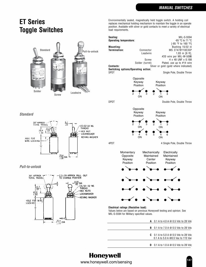
147www.honeywell.com/sensing
ET SeriesToggle Switches
Environmentally sealed, magnetically held toggle switch. A holding coilreplaces mechanical holding mechanism to maintain the toggle in an operateposition. Available with silver or gold contacts to meet a variety of electricalload requirements.
Sealing: MIL-S-5594Operating temperature: -65 °C to 71 °C
[-85 °F to 160 °F]Mounting: Bushing 15/32 inTermination: Connector MS 27478Y10E35P
Leadwire 1,83 m [6 ft],#20 wire per MIL-W-5086
Screw 4 x 48 UNF x 0.188Solder (turret) Plated, use up to #14 wire
Contacts: Silver or gold (gold where indicated)Switching options/Operating action:SPDT Single Pole, Double Throw
OppositeKeywayPosition
KeywayPosition
ON2 1 3
ON2 1 3
DPDT Double Pole, Double Throw
OppositeKeywayPosition
KeywayPosition
ON2 1 3
ON2 1 3
ON5 4 6
ON5 4 6
4PDT 4 Single Pole, Double Throw
MomentaryOppositeKeywayPosition
MechanicallyMaintained
CenterPosition
ElectricallyMaintained
KeywayPosition
Electrical ratings (Resistive load):Values below are based on previous Honeywell testing and opinion. SeeMIL-S-5594 for Military specified values.
A 0.1 A to 4.0 A @ 0.5 Vdc to 28 Vdc
B 0.1 A to 7.0 A @ 0.5 Vdc to 28 Vdc
C 0.1 A to 5.0 A @ 0.5 Vdc to 28 Vdc0.1 A to 5.0 A @0.5 Vac to 115 Vac
D 0.1 A to 1.0 A @ 0.5 Vdc to 28 Vdc
Solder LeadwireScrew
Standard Pull-to-unlock
Standard
Pull-to-unlock
MANUAL SWITCHES
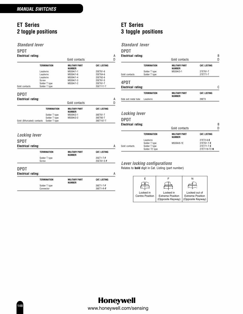
148www.honeywell.com/sensing
MANUAL SWITCHES
ET Series2 toggle positions
Standard leverSPDTElectrical rating: A
Gold contacts D
TERMINATION MILITARY PART CAT. LISTINGNUMBER
Leadwire M5594/1-1 25ET61-6Leadwire M5594/1-6 25ET64-6Leadwire M5594/1-4 25ET62-6Screw M5594/1-3 25ET61-SSolder T type M5594/1-2 25ET61-T
Gold contacts Solder T type 25ET117-T
DPDTElectrical rating: A
Gold contacts D
TERMINATION MILITARY PART CAT. LISTINGNUMBER
Solder T type M5594/2-1 26ET61-TSolder T type M5594/2-2 26ET65-T
Gold (Bifurcated) contacts Solder T type 26ET107-T
Locking leverSPDTElectrical rating: A
TERMINATION MILITARY PART CAT. LISTINGNUMBER
Solder T type 25ET1-T-FScrew 25ET61-S-F
DPDTElectrical rating: A
TERMINATION MILITARY PART CAT. LISTINGNUMBER
Solder T type 26ET1-T-FConnector 26ET1-R-F
ET Series3 toggle positions
Standard leverDPDTElectrical rating: B
Gold contacts D
TERMINATION MILITARY PART CAT. LISTINGNUMBER
Solder T type M5594/3-1 27ET61-TGold contacts Solder T type 27ET71-T
4PDTElectrical rating: C
TERMINATION MILITARY PART CAT. LISTINGNUMBER
Side exit metal tube Leadwire 29ET3
Locking leverDPDTElectrical rating: B
Gold contacts D
TERMINATION MILITARY PART CAT. LISTINGNUMBER
Leadwire 27ET2-6-ESolder T type M5594/6-1E 27ET61-T-E
Gold contacts Solder T type 27ET71-T-ESolder T2 type 27ET118-T2-N
Lever locking configurationsRelates to bold digit in Cat. Listing (part number)

149www.honeywell.com/sensing
NT Series toggle switches can meet the need for a rugged, cost-effectivetoggle switch. Quality construction features include a seal between thetoggle lever and bushing, and between the cover and case. Theseswitches can be used where panels are subject to splashes, hosedowns,or outdoor environments. The “Easy-Start” threaded bushing enablesquick alignment of mounting nut to decrease the chance of crossthreading. The panel stand-off with O-ring feature available on somelistings, eliminates the need for behind-the-panel hardware, providesuniform panel height, and provides a panel to cover seal.Locking toggle levers prevent accidental toggle movement. Theknobbed, toggle lever must be pulled out to change position.
Approvals: UL, CSASealing: IP 67/68, NEMA 3, 3R, 4, 13Operating temperature: -40 °C to 71 °C
[-40 °F to 160 °F]Mounting: Bushing 15/32 inTermination: Solder, Screw, Quick ConnectContacts: Silver cadmium oxide (Gold option available)
Electrical ratings (Resistive load):Values below are based on previous Honeywell testing and opinion.
A 0.5 A to 15 A at 0.5 Vac to 277 Vac|0.75 A at 115 Vdc|0.5 A to 20 A at 0.5 Vdc to 28 Vdc|0.5 A at 250 Vdc
B 0.5 A to 10 A at 0.5 Vac to 277 Vac|0.5 A to 15 A at 0.5 Vdc to 28Vdc|
0.5 A at 250 Vdc|0.75 A at 115 Vdc
C 0.75 A at 115 Vdc|0.5 A to 20 A at 0.5 Vdc to 28 Vdc|0.5 A to 15 A at 0.5 Vac to 277 Vac|0.5 A at 250 Vdc
D 0.5 A to 18 A at 0.5 Vdc to 28 Vdc|0.5 A to 10 A at 0.5 Vac to 277Vac|
0.5 A at 250 Vdc|0.75 A at 115 Vdc
E 0.5 A to 20 A at 0.5 Vdc to 28 Vdc|0.5 A to 15 A at 0.5 Vac to 277Vac|
0.5 A at 250 Vdc|0.75 A at 115 Vdc
UL/CSA Rating Code:
L191: 15 A-125, 250, 277 Vac; 1/2 Hp-125 Vac;1 Hp-250, 277 Vac; 5 A-120 Vac “L”
L192: 10 A-125, 250, 277 Vac; 1/4 Hp-125 Vac;1/2 Hp-250, 277 Vac; 3 A-125 Vac “L”
Application Note:Honeywell does not recommend the use of silver cadmium oxide switchcontacts in non-arcing loads. Non-arcing loads are generally loads lessthan 12 V and/or 0.5 A. NT switches use silver cadmium oxide contacts,but gold contact options are available.If you have specific questions, contact Honeywell.
NT SeriesSealed Toggle Switches
Flat base,Panel stand-off
Step base,Panel stand-off
Step base,no hardware
Note:No hardware indicates no mounting nuts, keying washer, lockwasher ortermination screws (if applicable).
MANUAL SWITCHES

150www.honeywell.com/sensing
MANUAL SWITCHES
Terminal circuit identification
One pole
Two pole
Four pole
Panel cutout
With locking ring Without locking ring
Note:1,4 mm/.06in MIN DEEP TO ACCOMMODATE LOCKINGRING. 15PA87 PANEL SEAL REQUIRES BLIND HOLETO ENSURE SEAL INTEGRITY
Lever locking configurationsRelates to bold digit in Cat. Listing (part number)
A D E L
Locked In3 Positions
Locked Out ofExtreme Position
(Keyway Side)Locked In
Center PositionLocked Out of
Center Position
G
Locked InExtreme Position
(Keyway Side)
NT Series, Step base switches
Standard lever
DIM "A"1 pole 29,5 mm (1.16 in)2 & 4 pole 34,4 mm (1.35 in)
NOTES:1. Locking levers have 10,7 mm (0.42 in) Ø2. Locking ring, lockwasher, 2 hexnuts and terminal screws are provided unassembled
Panel stand off toggleTo order an NT Series toggle switch with panel stand-off feature, insert “6”in front of any standard listing.Example: to order panel stand-off version of standard bushing 1NT1-7, alternumber to 61NT1-7.
AB
1,52 (0.06)
Ø 6,10(0.24)
17,02(0.67)
12,45(0.49)
7,37 (0.29)
DIM "A" DIM "B"1 pole 29,5 mm (1.16 in) 23,11 mm (0.91 in)2 pole 34,4 mm (1.35 in) 27,94 mm (1.10 in)
Solder terminals Quick Connect terminals
7,60.3
5,30.21
3,20.12

151www.honeywell.com/sensing
NT Series, Step base,2 position switches
Standard lever1 pole, screw terminals
CIRCUITRY OPERATING ELECTRICAL UL/CSA CAT.LISTINGACTION* RATING RATINGSPST 1 A L191 1NT1-2SPST 2 B L192 1NT1-6SPDT 3 A L191 1NT1-3
No hardware SPDT 3 A L191 1NT1-3-NHSPDT 4 B L192 1NT1-8
No hardware SPDT 4 B L192 1NT1-8-NH
1 pole, Quick Connect terminalsCIRCUITRY OPERATING ELECTRICAL UL/CSA CAT.LISTING
ACTION* RATING RATINGSPST 2 A L191 1NT91-2
1 pole, solder terminalsCIRCUITRY OPERATING ELECTRICAL UL/CSA CAT.LISTING
ACTION* RATING RATINGSPST 1 A L191 11NT1-2SPDT 3 A L191 11NT1-3
2 pole, screw terminalsCIRCUITRY OPERATING ELECTRICAL UL/CSA CAT.LISTING
ACTION* RATING RATINGDPST 5 C L191 2NT1-2DPDT 6 C L191 2NT1-3
No hardware DPDT 6 C L191 2NT1-3-NHDPDT 7 D L192 2NT1-8
No hardware DPDT 7 D L192 2NT1-8-NH
2 pole, solder terminalsCIRCUITRY OPERATING ELECTRICAL UL/CSA CAT.LISTING
ACTION* RATING RATINGDPDT 6 C L191 12NT1-3
4 pole, screw terminalsCIRCUITRY OPERATING ELECTRICAL UL/CSA CAT.LISTING
ACTION* RATING RATING4PDT 8* E L191 4NT1-3
4 pole, solder terminalsCIRCUITRY OPERATING ELECTRICAL UL/CSA CAT.LISTING
ACTION RATING RATING4PDT 8* E L191 14NT1-3
Locking lever1 pole, screw terminals
CIRCUITRY OPERATING ELECTRICAL UL/CSA CAT.LISTINGACTION* RATING RATING
SPST 1 A L191 1NT1-2GSPDT 3 A L191 1NT1-3D
* Operating action 1 to 8
2 Position Switching options/Operating action* (1 to 8):
SPST Single Pole, SingleThrow
1
KeywayPosition
OppositeKeywayPosition
2 32 3ONOFF
2
KeywayMomentaryPosition
OppositeKeywayPosition
1 2 1 2ON OFF
SPDT Single Pole, Double Throw
3
KeywayPosition
OppositeKeywayPosition
1 2 3 1 32ON ON
4
KeywayMomentary
Position
OppositeKeywayPosition
1 2 3 1 32ON ON
DPST Double Pole, Single Throw
5
KeywayPosition
OppositeKeywayPosition
2 3 32
6 5 6 5OFF ON
DPDT Double Pole, Double Throw
6
KeywayPosition
OppositeKeywayPosition
1 2 3 1 32
6 5 4 6 45ON ON
7
KeywayMomentary
Position
OppositeKeywayPosition
1 2 3 1 32
6 5 4 6 45ON ON
4PDT 4 Pole, Double Throw
8
KeywayPosition
OppositeKeywayPosition
3 2 1 3 2 1
6 5 4 6 5 4
9 8 7 9 8 7
12 11 10 ON
12 11 10 ON
MANUAL SWITCHES

152www.honeywell.com/sensing
MANUAL SWITCHES
NT Series, Step base,3 position switches
Standard lever1 pole, screw terminals
CIRCUITRY OPERATING ELECTRICAL UL/CSA CAT. LISTINGACTION** RATING RATING
SPDT 9 A L191 1NT1-1SPDT 10 B L192 1NT1-5SPDT 11 B L192 1NT1-7
No hardware SPDT 11 B L192 1NT1-7-NHSPDT 11 B L191 1NT231-7
Panel stand off SPDT 11 D L192 61NT1-7
1 pole, Quick Connect terminalsCIRCUITRY OPERATING ELECTRICAL UL/CSA CAT. LISTING
ACTION** RATING RATINGSPDT 11 B L192 1NT91-7
1 pole, solder terminalsCIRCUITRY OPERATING ELECTRICAL UL/CSA CAT. LISTING
ACTION** RATING RATINGSPDT 11 B L192 11NT1-7
No hardware SPDT 11 B L192 11NT1-7-NH
2 pole, screw terminalsCIRCUITRY OPERATING ELECTRICAL UL/CSA CAT. LISTING
ACTION** RATING RATINGDPDT 12 C L191 2NT1-1
No hardware DPDT 12 C L191 2NT1-1-NHDPDT 13 C L191 2NT1-10DPDT 17 D L192 2NT1-5DPDT 15 D L192 2NT1-50DPDT 16 D L192 2NT1-7
No hardware DPDT 16 D L192 2NT1-7-NHDPDT 14 D L192 2NT1-70DPDT 16 D L192 2NT231-7
Gold contacts/ DPDT 14 D L192 2NT889-70long lever
2 pole, Quick Connect terminalsCIRCUITRY OPERATING ELECTRICAL UL/CSA CAT. LISTING
ACTION** RATING RATINGDPDT 16 D L192 2NT91-7
4 pole, screw terminalsCIRCUITRY OPERATING ELECTRICAL UL/CSA CAT. LISTING
ACTION** RATING RATING4PDT 18 E L191 4NT1-1
Locking lever1 pole, screw terminals
CIRCUITRY OPERATING ELECTRICAL UL/CSA CAT. LISTINGACTION** RATING RATING
SPDT 11 B L192 1NT1-7ESPDT 11 B L191 1NT20-7E
4 pole, screw terminalsCIRCUITRY OPERATING ELECTRICAL UL/CSA CAT. LISTING
ACTION** RATING RATING4PDT 18 E L191 4NT1-1A
**Operating action 9 to 18
3 Position Switching options/Operating action** (9 to 18):
SPDT Single Pole, Double Throw
9
KeywayPosition
CenterPosition
OppositeKeywayPosition
1 2 3 1 32 1 32ON OFF ON
10
KeywayMomentaryPosition
CenterPosition
OppositeKeywayPosition
1 2 3 1 32 1 32ON OFF ON
11
KeywayMomentaryPosition
CenterPosition
OppositeKeywayMomentaryPosition
1 2 3 1 32 1 32ON OFF ON
DPDT Double Pole, Double Throw
12
KeywayPosition
OppositeKeywayPosition
1 2 3 1 32
6 5 4 6 45ON ON
13
KeywayMaintained
Position
CenterMaintained
Position
OppositeKeyway
MaintainedPosition
3 2 1 3 2 1 3 2 1
6 5 4 6 5 4 6 5 4 ON ON ON
14
KeywayMomentary
Position
CenterMaintained
Position
OppositeKeyway
MomentaryPosition
3 2 1 3 2 1 3 2 1
6 5 4 6 5 4 6 5 4 ON ON ON
15
KeywayMomentary
Position
CenterMaintained
Position
OppositeKeyway
MaintainedPosition
3 2 1 3 2 1 3 2 1
6 5 4 6 5 4 6 5 4 ON ON ON
16
KeywayMomentaryPosition
CenterPosition
OppositeKeywayMomentaryPosition
1 2 3 1 32 1 32
6 5 4 6 45 6 45ON OFF ON
17
KeywayMomentaryPosition
CenterPosition
OppositeKeywayPosition
1 2 3 1 32 1 32
6 5 4 6 45 6 45ON OFF ON
4PDT 4 Pole, Double Throw
18
KeywayPosition
CenterPosition
OppositeKeywayPosition
1 2 3 1 32 1 32
6 5 4 6 45 6 45
ON OFF ON
9 8 7 9 78 9 78
12 11 10 12 11 10 12 11 10
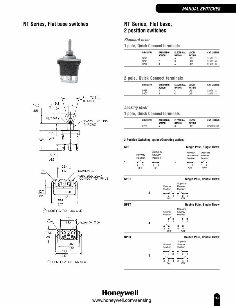
153www.honeywell.com/sensing
NT Series, Flat base switches NT Series, Flat base,2 position switches
Standard lever1 pole, Quick Connect terminals
CIRCUITRY OPERATING ELECTRICAL UL/CSA CAT. LISTINGACTION RATING RATING
SPST 1 A L191 31NT91-2SPST 2 B L192 31NT91-6SPDT 3 A L191 31NT91-3
2 pole, Quick Connect terminalsCIRCUITRY OPERATING ELECTRICAL UL/CSA CAT. LISTING
ACTION RATING RATINGDPST 4 C L191 32NT91-2DPDT 5 C L191 32NT91-3
Locking lever1 pole, Quick Connect terminals
CIRCUITRY OPERATING ELECTRICAL UL/CSA CAT. LISTINGACTION RATING RATING
DPDT 5 C L191 32NT291-3G
2 Position Switching options/Operating action:
SPST Single Pole, Single Throw
1
KeywayPosition
OppositeKeywayPosition
2 32 3ONOFF
2
KeywayMomentaryPosition
OppositeKeywayPosition
1 2 1 2ON OFF
SPDT Single Pole, Double Throw
3
KeywayPosition
OppositeKeywayPosition
1 2 3 1 32ON ON
DPST Double Pole, Single Throw
4
KeywayPosition
OppositeKeywayPosition
2 3 32
6 5 6 5OFF ON
DPDT Double Pole, Double Throw
5
KeywayPosition
OppositeKeywayPosition
1 2 3 1 32
6 5 4 6 45ON ON
MANUAL SWITCHES

154www.honeywell.com/sensing
MANUAL SWITCHES
NT Series, Flat base,3 position switches
Standard lever1 pole, Quick Connect terminals
CIRCUITRY OPERATING ELECTRICAL UL/CSA CAT. LISTINGACTION RATING RATING
SPDT 6 A L191 31NT91-1SPDT 7 B L192 31NT91-7
2 pole, Quick Connect terminalsCIRCUITRY OPERATING ELECTRICAL UL/CSA CAT. LISTING
ACTION RATING RATINGDPDT 8 C L191 32NT91-1DPDT 10 D L192 32NT91-7
No hardware DPDT 10 D L192 32NT91-7-NH
Locking lever2 pole, Quick Connect terminals
CIRCUITRY OPERATING ELECTRICAL UL/CSA CAT. LISTINGACTION RATING RATING
DPDT 11 D L192 32NT291-5EDPDT 9 D L192 32NT94-70L
3 Position Switching options/Operating action:
SPDT Single Pole, Double Throw
6
KeywayPosition
CenterPosition
OppositeKeywayPosition
1 2 3 1 32 1 32ON OFF ON
7
KeywayMomentaryPosition
CenterPosition
OppositeKeywayMomentaryPosition
1 2 3 1 32 1 32ON OFF ON
DPDT Double Pole, Double Throw
8
KeywayPosition
CenterPosition
OppositeKeywayPosition
1 2 3 1 32 1 32
6 5 4 6 45 6 45ON OFF ON
9
KeywayMomentary
Position
CenterMaintained
Position
OppositeKeyway
MomentaryPosition
3 2 1 3 2 1 3 2 1
6 5 4 6 5 4 6 5 4 ON ON ON
10
KeywayMomentaryPosition
CenterPosition
OppositeKeywayMomentaryPosition
1 2 3 1 32 1 32
6 5 4 6 45 6 45ON OFF ON
11
KeywayMomentaryPosition
CenterPosition
OppositeKeywayPosition
1 2 3 1 32 1 32
6 5 4 6 45 6 45ON OFF ON

155www.honeywell.com/sensing
TS SeriesToggle Switches
TS Series switches may be used in applications where manual operationis desired. Special on-on-on circuitry can also be furnished. They have2- or 3-position, momentary and maintained action switches with 1- and2-pole circuitry. Switches have solder, screw or quick-connectterminations.Approvals: UL, CSAOperating temperature: -54 °C to 71 °C
[-65 °F to 160 °F]Mounting: Bushing 15/32 inLever/bushing material: Bright nickelTermination: Solder, Screw, Quick ConnectContacts: Silver tin oxide and indium oxide
Electrical ratings* (Resistive load): 0.4 A to 10 A at 126 Vac to 277 Vac|0.4 A to 20 A at 0.5 Vac to 125 Vac
* Values are based on previous Honeywell testing and opinion.UL/CSA Rating Code:
L311: 10 A 277 Vac, 20 A 125 Vac; 3/4 Hp-125, 250 Vac
L312: 10 A 277 Vac, 20 A 125 Vac; 11/2 Hp-125, 250 Vac
11TSOne pole
12TSTwo pole
Panel cutout
With locking ringWithout locking ring
MANUAL SWITCHES

156www.honeywell.com/sensing
MANUAL SWITCHES
TS Series2 position switches
Standard leverScrew terminals
CIRCUITRY OPERATING UL/CSA CAT. LISTINGACTION RATING
SPST 1 L311 11TS15-2SPST 2 L311 11TS15-6DPST 4 L312 12TS15-2DPDT 5 L312 12TS15-3
Quick Connect terminalsCIRCUITRY OPERATING UL/CSA CAT. LISTING
ACTION RATINGSPST 1 L311 11TS95-2DPDT 5 L312 12TS95-3
Solder terminalsCIRCUITRY OPERATING UL/CSA CAT. LISTING
ACTION RATINGSPDT 3 L311 11TS115-3
Furnished unassembled DPDT 5 L312 12TS115-3
2 Position Switching options/Operating action:
SPST Single Pole, Single Throw
1
KeywayPosition
OppositeKeywayPosition
2 32 3ONOFF
2
KeywayMomentaryPosition
OppositeKeywayPosition
1 2 1 2ON OFF
SPDT Single Pole, Double Throw
3
KeywayPosition
OppositeKeywayPosition
1 2 3 1 32ON ON
DPST Double Pole, Single Throw
4
KeywayPosition
OppositeKeywayPosition
2 3 32
6 5 6 5OFF ON
DPDT Double Pole, Double Throw
5
KeywayPosition
OppositeKeywayPosition
1 2 3 1 32
6 5 4 6 45ON ON
TS Series3 position switches
Standard leverScrew terminals
CIRCUITRY OPERATING UL/CSA CAT.LISTING ACTION RATING
SPDT 6 L311 11TS15-1SPDT 7 L311 11TS15-7DPDT 8 L312 12TS15-7
Quick Connect terminalsCIRCUITRY OPERATING UL/CSA CAT.
LISTING ACTION RATINGSPDT 7 L311 11TS95-7
Furnished unassembled DPDT 9 L312 12TS95-10
3 Position Switching options/Operating action:
SPDT Single Pole, Double Throw
6
KeywayPosition
CenterPosition
OppositeKeywayPosition
1 2 3 1 32 1 32ON OFF ON
7
KeywayMomentaryPosition
CenterPosition
OppositeKeywayMomentaryPosition
1 2 3 1 32 1 32ON OFF ON
DPDT Double Pole, Double Throw
8
KeywayMomentaryPosition
CenterPosition
OppositeKeywayMomentaryPosition
1 2 3 1 32 1 32
6 5 4 6 45 6 45ON OFF ON
9
KeywayMaintained
Position
CenterMaintained
Position
OppositeKeyway
MaintainedPosition
3 2 1 3 2 1 3 2 1
6 5 4 6 5 4 6 5 4 ON ON ON

157www.honeywell.com/sensing
TP SeriesRocker Switches
Honeywell’s 2 and 3 position, pushbutton action rocker switches aredust and splash-proof sealed. They can be provided with or withoutbuttons. The switches are available as flush or panel mount, a largeselection of rocker colors, circuitries and electrical terminations. Versionsare available with silver or gold contacts to meet a variety of electricalload requirements. For options other than those shown below, contactHoneywell for more information.
Switching options/Operating action:
2 Position SwitchesSPST Single Pole, Single Throw
1
IdentificationLug
Position
OppositeIdentification
LugPosition
2 32 3ONOFF
2
IdentificationLug
MomentaryPosition
OppositeIdentification
LugPosition
1 2 1 2ON OFF
SPDT Single Pole, Double Throw
3
IdentificationLug
Position
OppositeIdentification
LugPosition
1 2 3 1 32ON ON
DPDT Double Pole, Double Throw
4
IdentificationLug
Position
OppositeIdentification
LugPosition
1 2 3 1 32
6 5 4 6 45ON ON
5
IdentificationLug
MomentaryPosition
OppositeIdentification
LugPosition
1 2 3 1 32
6 5 4 6 45ON ON
3 Position SwitchesSPDT Single Pole, Double Throw
6
IdentificationLug
MomentaryPosition
CenterPosition
OppositeIdentification
LugMomentary
Position
1 2 3 1 32 1 32ON OFF ON
DPDT Double Pole, Double Throw
7
IdentificationLug
MomentaryPosition
CenterPosition
OppositeIdentification
LugMomentary
Position
1 2 3 1 32 1 32
6 5 4 6 45 6 45ON OFF ON
Approvals: UL, CSA, CEOperating temperature: -54 °C to 71 °C
[-65 °F to 160 °F]Mounting: Above Panel and Flush PanelTermination: ScrewContacts: Silver cadmium oxide
Electrical ratings (Resistive load):Values below are based on previous Honeywell testing and opinion.
A 0.5 A to 18 A at 0.5 Vdc to 28 Vdc|0.5 A to 10 A at 0.5 Vac to 277 Vac|0.75 A at 115 Vdc|0.5 A at 250 Vdc
B 0.5 A to 20 A at 0.5 Vdc to 28 Vdc|0.75 A at 115 Vdc|0.5 A at 250 Vdc|0.5 A to 15 A at 0.5 Vac to 277 Vac
C 0.5 A to 10 A at 0.5 Vac to 277 Vac|0.75 A at 115 Vdc|0.5 A at 250 Vdc|0.5 A to 15 A at 0.5 Vdc to 28 Vdc
UL/CSA Rating Code:
L191: 15 A-125, 250, 277 Vac; 1/2 Hp-125 Vac;1 Hp-250, 277 Vac; 5 A-120 Vac “L”
L192: 10 A-125, 250, 277 Vac; 1/4 Hp-125 Vac;1/2 Hp-250, 277 Vac; 3 A-125 Vac “L”
Application Note:Honeywell does not recommend the use of silver cadmium oxide switchcontacts in non-arcing loads. Non-arcing loads are generally loads less than12 V and/or 0.5 A. TP switches use silver cadmium oxide contacts, but goldcontact options are available.If you have specific questions, contact Honeywell.
MANUAL SWITCHES

158www.honeywell.com/sensing
MANUAL SWITCHES
Above panel mounting
Panel cutout
Flush panel mounting
Terminals
Single pole
Double pole
2 Position
Flush Panel MountBUTTON CIRCUITRY OPERATING ELECTRICAL UL/CSA CAT. LISTING
ACTION RATING RATINGTranslucent SPST 2 C L192 1TP1-6No SPST 1 B L191 1TP8-2No SPDT 3 B L191 1TP8-3
Above Panel MountBUTTON CIRCUITRY OPERATING ELECTRICAL UL/CSA CAT. LISTING
ACTION RATING RATINGTranslucent DPDT 5 A L192 2TP216-8No DPDT 4 B L191 2TP7-3
Button OptionsButtons are removable and interchangeable.They measure 22,1 mm x 37,1 mm [0.87 in x 1.46 in].
COLOUR CAT. LISTINGTranslucent 12PA6Transparent 12PA4White* 12PA5-WYellow* 12PA5-YBlack* 12PA5-BKGreen* 12PA5-GRed* 12PA5-RBlue* 12PA5-BL
* Opaque
3 Position
Flush Panel MountBUTTON CIRCUITRY OPERATING ELECTRICAL UL/CSA CAT. LISTING
ACTION RATING RATINGTransparent SPDT 6 C L192 1TP12-7Translucent SPDT 6 C L192 1TP201-7No SPDT 6 C L192 1TP8-7Transparent DPDT 7 A L192 2TP12-7Translucent DPDT 7 A L192 2TP1-7
Above Panel MountBUTTON CIRCUITRY OPERATING ELECTRICAL UL/CSA CAT. LISTING
ACTION RATING RATINGTranslucent DPDT 7 A L192 2TP216-7

159www.honeywell.com/sensing
MANUAL SWITCHES
The FR Series illuminated and non-illluminated full-size sealed rockerswitches offer enhanced design flexibility and set new standards for bothperformance and reliability. The switches are designed to fit industrystandard mounting holes of 44,0 mm x 22,0 mm [1.734 in x 0.867 in]and offer a variety of switch and lamp circuit combinations.
Approvals: UL, CSAMechanical life: 250,000 cycles minimumElectrical life: 50,000 cycles (mom.); 100,000 cycles (maint.)Sealing: IP 67Operating temperature: -40 °C to 85 °C [-40 °F to 185 °F]Termination style: 6,35 mm x 0,81 mm [0.25 in x 0.032 in]
quick connect tabs
FR SeriesSealed Rocker Switches
OPTIONS
FRN SERIES
One poleCIRCUITRY (POS. 3, 2, 1) BEZEL/ACTUATOR COLOR CAT. LISTINGOff, None, On Black/Black FRN91-12BBOff, None, On (Mom.) Black/Black FRN91-16BBOff (Mom.), None, On Black/Black FRN91-14BBOn, None, On Black/Black FRN91-13BBOn (Mom.), None, On Black/Black FRN91-18BBOn, Off, On Black/Black FRN91-11BBOn (Mom.), Off, On Black/Black FRN91-15BBOn (Mom.), Off, On (Mom.) Black/Black FRN91-17BB
Two polesCIRCUITRY (POS. 3, 2, 1) BEZEL/ACTUATOR COLOR CAT. LISTINGOff, None, On Black/Black FRN91-22BBOff, None, On (Mom.) Black/Black FRN91-26BBOff (Mom.), None, On Black/Black FRN91-24BBOn, None, On Black/Black FRN91-23BBOn (Mom.), None, On Black/Black FRN91-28BBOn, Off, On Black/Black FRN91-21BBOn (Mom.), Off, On Black/Black FRN91-25BBOn (Mom.), Off, On (Mom.) Black/Black FRN91-27BB

160www.honeywell.com/sensing
OPTIONS
FRL SERIES
Two poles, Illumination Style C, 12 VCIRCUITRY (POS. 3, 2, 1) LAMP/LAMP LENS/LENS CAT. LISTINGOff, None, On Green/Amber Large white trans./White bar FRL91-22CGA3-BB79On, None, On Green/Green Large white trans./White bar FRL91-23CGG3-BB79On, Off, On Green/Green Large white trans./Large white trans. FRL91-21CGG3-BB77On (Mom.), Off, On (Mom.) Green/Green Large white trans./Large white trans. FRL91-27CGG3-BB77
MANUAL SWITCHES
AccessoriesDESCRIPTION CAT. LISTINGRocker Boot FR-01

161www.honeywell.com/sensing
SR SeriesSealed Rocker Switches
OPTIONS
SRN SERIES
One poleCIRCUITRY (POS. 3, 2, 1) BEZEL/ACTUATOR COLOR CAT. LISTINGOff, None, On Black/Black SRN91-12BBOff, None, On (Mom.) Black/Black SRN91-16BBOff (Mom.), None, On Black/Black SRN91-14BBOn, None, On Black/Black SRN91-13BBOn (Mom.), None, On Black/Black SRN91-18BBOn, Off, On Black/Black SRN91-11BBOn (Mom.), Off, On Black/Black SRN91-15BBOn (Mom.), Off, On (Mom.) Black/Black SRN91-17BB
Two polesCIRCUITRY (POS. 3, 2, 1) BEZEL/ACTUATOR COLOR CAT. LISTINGOff, None, On Black/Black SRN91-22BBOff, None, On (Mom.) Black/Black SRN91-26BBOff (Mom.), None, On Black/Black SRN91-24BBOn, None, On Black/Black SRN91-23BBOn (Mom.), None, On Black/Black SRN91-28BBOn, Off, On Black/Black SRN91-21BBOn (Mom.), Off, On Black/Black SRN91-25BBOn (Mom.), Off, On (Mom.) Black/Black SRN91-27BB
MANUAL SWITCHES
The SR Series illuminated and non-illluminated full-size sealed rockerswitches offer enhanced performance in a flexible package. The switchesare available in single or souble pole configurations, have an optionalpanel seal, and the SRL Series can be illuminated with square or bar-shaped lenses.
Approvals: UL, CSAMechanical life: 150,000 cycles minimumElectrical life: 50,000 cycles (mom.); 100,000 cycles (maint.)Sealing: Dual switch seal certified to IP66/IP68Operating temperature: -40 °C to 85 °C [-40 °F to 185 °F]Termination style: Offered in both 8 and 10 terminal base options.
AMP and Packard compatible connectors available.

162www.honeywell.com/sensing
AccessoriesDESCRIPTION CAT. LISTINGConnector Housing HRSR-01
DESCRIPTION CAT. LISTINGConnector Housing SR-01
OPTIONS
SRL SERIES
Two poles, Illumination Style A, 12 VCIRCUITRY (POS. 3, 2, 1) LAMP/LAMP CAT. LISTINGOff, None, On Red/None SRL91-22ARN3-BB9N
Two poles, Illumination Style U, 12 VCIRCUITRY (POS. 3, 2, 1) LAMP/LAMP LED VOLTAGE CAT. LISTINGOn, None, On Red/Red 12 V SRL91-23URR3-BB99On, Off, On Red/Red 12 V SRL91-21URR3-BB99On (Mom.), Off, On (Mom.) Red/Red 12 V SRL91-27URR3-BB99Off, None, On Green/Amber 12 V SRL91-22UGA3-BB99On, None, On Green/Green 12 V SRL91-23UGG3-BB99On, Off, On Green/Green 12 V SRL91-21UGG3-BB99Off, None, On Green/Green 12 V SRL91-22UGG3-BB99
MANUAL SWITCHES

163www.honeywell.com/sensing
MANUAL SWITCHES
MR SeriesMiniature Rocker Switches
OPTIONS
MR SERIES
Non-IlluminatedPOLES CIRCUITRY CAT. LISTING1 N MR93-12BBN2 N MR93-22BBN
Illuminated, Single PoleLAMP CIRCUITRY* ACTUATOR COLOR CAT. LISTING12 V LED 3 Clear Red MR93-122B312 V LED 3 Clear Green MR93-124B3125 V Neon J Clear Red MR93-122BJ250 V Neon K Clear Amber MR93-121BK
Illuminated, Double PoleLAMP CIRCUITRY* ACTUATOR COLOR CAT. LISTING12 V LED 3 Clear Red MR93-222B312 V LED 3 Clear Green MR93-224B324 V Neon 4 Clear Amber MR93-221B4
These miniature rocker switches offer a variety of aesthetic andfunctional options ranging from circuit configurations to ac and dcratings. They feature industry standard dimensions, an easy snap-inmounting method, and offer one-or-two pole switches in numeroussingle-throw and double-throw maintained and momentary circuits. Theilluminated and non-illuminated miniature switches are intended to meetthe needs of a wide variety of industries and potential applications. Thesilver-alloy contacts will handle a range of electrical loads. Theilluminated products offer LED or neon-style lamps.
Approvals: UL, CSAMechanical life: 100,000 cycles minimumElectrical life: 50,000 cyclesDielectric strength UL/CSA: 1000 VOperating temperature: 0 °C to 85 °C [32 °F to 185 °F]Termination style: 4,75 mm x 0,81 mm tab QC
[0.187 in x 0.032 in] tab QC
* Electrical Ratings (UL/CSA)N 8 A, 125 Vac; 12 A, 125 Vac, ½ HP, 125 Vac - 250 Vac; UL, CSA1 N/A2 12 A, 6 V3 12 A, 12 V4 12 A, 24 VA 12 A, 6 VC 12 A, 12 VE 12 A, 18 VH 12 A, 24 VJ 12 A, 125 Vac; UL, CSAK 8 A, 250 Vac; UL, CSA

164www.honeywell.com/sensing
MRS SeriesMiniature Rocker Switches
OPTIONS
MRS SERIES
One poleCIRCUITRY (POS. 3, 2, 1) BEZEL/ACTUATOR COLOR ELEC. RATING* CAT. LISTINGOff, None, On Black/Black 1 MRS93-12BBOff, None, On (Mom.) Black/Black 3 MRS93-16BBOff (Mom.), None, On Black/Black 3 MRS93-14BBOn, None, On Black/Black 1 MRS93-13BBOn (Mom.), None, On Black/Black 3 MRS93-18BBOn, Off, On Black/Black 2 MRS93-11BBOn (Mom.), Off, On Black/Black 2 MRS93-15BBOn (Mom.), Off, On (Mom.) Black/Black 2 MRS93-17BB
These subminiature rocker switches offer a variety of aesthetic andfunctional options ranging from circuit configurations to ac and dcratings. They feature industry standard dimensions, an easy snap-inmounting method, and offer one-or-two pole switches in numeroussingle-throw and double-throw maintained and momentary circuits.These non-illuminated switches are often ideal for applications wherethere is restricted space behind the panel. It fits in a standardrectangular cutout and is designed to fit easily and securely. The snap-action contacts provide the user with a crisp, positive response. Avariety of circuitry choices will appeal to many industry segments.
Approvals: UL, CSAMechanical life: 100,000 cycles minimumElectrical life: 50,000 cycles (mom.); 100,000 cycles (maint.)Dielectric strength UL/CSA: 1000 VOperating temperature: 0 °C to 85 °C [32 °F to 185 °F]Termination style: 4,75 mm x 0,81 mm tab QC
[0.187 in x 0.032 in] tab QC
MANUAL SWITCHES
* Electrical Ratings (UL/CSA)1 10 A, 125 Vac; 10 A, 250 Vac; ¼ HP, 125 Vac - 250 Vac2 8 A, 125 Vac - 250 Vac; ¼ HP, 125 Vac - 250 Vac3 12 A, 125 Vac; 6 A, 250 Vac; ¼ HP, 125 Vac - 250 Vac

165www.honeywell.com/sensing
Manual Switches andPushbuttonsManual Switches. Designed by industrial designers to achieve balancebetween harmonious appearance and ergonomics, AML AdvancedManual Line has pushbuttons, paddles, and rockers; with LED,incandescent, and neon illumination. Plus, matching indicators and LEDannunciators. A smaller cousin, MML Minature Manual Line, offers manyAML features in a space-saving size.
Pushbuttons. A wide array of different pushbutton families, many withlighted display and matching indicators. Includes Series 2, an easilyassembled modular design with many color display/control options; andcompact PB unlighted pushbuttons.
MANUAL SWITCHES AND PUSHBUTTONS

166www.honeywell.com/sensing
Electrical Data Solid State:5, 6 - 16, or4.5 - 24 Vdc
AML MML
Panel Area 20,5 mm [0.80 in] squareand 20,5 mm x 30 mm[0.80 in x 1.20 in]
Display 15,0 mm [0.59 in] square and15,0 mm x 25,0 mm [0.59 in x0.99 in] buttons
Pushbutton or lens cap (indica-tor only) buttons with up to 3-section display. Various button heights. Transmitted, projected, and dead front hidden legend/color
Illumination Incandescent T-1-3/4 lamps – 6 V, 14 V, and 28 VLEDs - 2 V, 4 V, 5 V, 10 V, 15 VNeon lamps – 125 V, 250 V
Behind PanelDepth (max.)
43,1 mm [1.7 in]
Mounting Snap-in individual, strip, matrix, sub-panel, P.C. board mounting
Termination Solder, quick-connect,P.C. board, push-on
Sealing Optional panel seal
SpecialFeatures
Along with companion rockers andpaddles, provides the mostadvanced and complete line ofmanual controls available
Electroniccontrol: Up
to 3 A, 125 Vac
Power Duty:up to 10 A,
125/250Vac
Circuitry Currentsinking
1, 2, and 4Form C
2 pole,Form X
Agency Listings
UL, CSA, CDE and CE (selectedproducts)*
PWB mount: 10,2 mm [0.40 in] square and 15,2 mm x 10,2 mm [0.60 in x 0.40 in], except 2-pole power duty paddles and rockers
Pushbuttons: 6,6 mm [0.26 in] squareand 11,7 mm x 6,6 mm [0.46 in x0.26 in]. Transmitted color
Rockers: Optional lenses for transmitted color
LEDs - 1.7 V, 2.1 V, 2.2 V, 2.3 VIncandescent T-1 lamps – 5 V (other voltages available)
17,0 mm [0.67 in]
Printed wiring board, snap-in strip,matrix
Printed wiring board, solder,quick-connect
–
–
Solid State:5 Vdc to 24 Vdc
ElectronicControl: Up
to 1 A, 125 Vac res.
Power Duty Pushbuttons:
up to 6 A,250 Vac
res.
Currentsinking
1 or 2Form C
1 or 2Form X
UL and CSA
Series 4
21,3 x mm x 26,2 mm[0.84 in x 1.03 in]
13,5 mm x 18.0 mm [0.53 in x0.71 in] buttons
Single section displayTransmitted, projected, anddead front hidden color
Incandescent T-3-1/4 lamps14 V, 28 V
6,1 mm [2.4 in]
Snap-in individual or stripmounting; top panel orsub-panel mounting
Solder, quick-connect,P.C. board
–
Can be furnished with lockedbutton feature for use in publicareas where tampering is aproblem
up to 10 A
1 or 2 Form C
UL, CSA
* For complete international compliance information, contact the 800 number.
MANUAL SWITCHES AND PUSHBUTTONS

167www.honeywell.com/sensing
Series 2 PB
25,4 mm x 35,8 mm [1.0 in x 1.41 in]21,8 mm x 34,3 mm [0.86 in x 1.35 in]
21,6 mm x 27,4 mm [0.85 in x1.08 in] buttons.
1-4 section displayTransmitted and projected color
Incandescent T-1-3/4 lamps, 28 V
83,3 mm [3.28 in]
Snap-in flange mount and units withmounting barriers for individualor strip mount
Solder, quick-connect,and screw terminals
–
–
UL, CSA
Depends on type and number ofbasic switches
8,1 mm [0.32 in] dia., and otherbutton sizes
Colored buttons
Threaded bushing
Solder terminals
Panel seal version. Hermetically sealed units
Compact size
Solid state:5, 6 -16, or
4.5 - 24 Vdc
ElectronicControl: Up
to 3 A, 125 Vac
Power Duty Pushbuttons:up to 15 A,
125/250 Vac
Current sinking2 or 3 positions,mom. or maint.
1, 2, & 4 Form C, 2 or 3 positions,mom. or maint.
1 or 2 Form A2 pos.maint.
UL, CSA. Some meet MIL-S-8805 andMIL-STD-1080D
AML
20,5 x mm x 30,5 mm[0.80 in x 1.20 in]
Paddle:Full and splitcolor covers
–
–
Snap-in individual, strip,matrix, sub-panel, P.C.board mounting
Solder, quick-connect,P.C. board, push on
–
Matches display/control optionsof AML pushbuttons
UL, CSA, VDC, and CE (selectedproducts)*
1 A to 20 A, 125 Vac, 250 Vac,480 Vac, depending on switchmodule specified
1 - 4 Form C
–
–
2 A to 5 A, 125/250 Vac
1 - 4 Form C
Rocker:Full and splitcolor rockers
MANUAL SWITCHES AND PUSHBUTTONS

168www.honeywell.com/sensing
AML SeriesAdvanced Manual LineSwitches
In Front of the PanelCoordinated, attractive appearance. AML features innovationsdesigned by industrial designers aimed at achieving the best balance ofhuman factors and aesthetic appearance. Operator height, bezel size,and the compatability of square and rectangular shapes blend withother components to harmonize your panel. There’s no visual clutter todistract from man/machine communication.This comprehensive line of lighted and unlighted manual controlsfeatures:
• Pushbuttons for high and intermediate frequency functions.• Rocker and paddle switches, with two or three positions, for less
frequent control functions.• Plus lighted indicators and annunciators which complement AML’s
universal appeal.Various controls can be matched with their functions to accommodatethe most natural and efficient habit pattern relfex. Keylock-operatedswitches can be used to assure “authorized personnel only” access.Display flexibility. AML offers a choice of five legend sizes, four buttonheights, full or split second display, and illunimation by incandescentlamps, LEDs or neons. Colors are bright and uniform, providing astrong definition and good visibility. (Non-illuminated devices have thesame attractive colors.)Color display options include:
• Transmitted color – color can be distinguished whether the lamp isOn or Off.
• Dead front – display appears black, until illumination causes legendand color to appear.
• Projected color – white display is diffused with color whenilluminated.
Behind the PanelAMLs simple, cost-effective design provides many behind-panel benefitsfor the designer and installer/user.Simple to install. They snap in from the panel front individually or invertical or horizontal strips; or in subpanel mounted strips and matricesthat can be pre-assembled and pre-wired.Electrical flexibility. Solid state switches with Hall-effect integratedcircuits interface directly with microprocessors and other logic-leveldevices. These ICs were first applied in MICRO SWITCH solid statekeyboards. Today, many MICRO SWITCH products incorporate the Hall-effect technology to meet a wide range of position sensing and manualcontrol needs.Electronic control switches with gold or silver contacts, and 1, 2, or 4poles, will handle up to three amps. Including an encoded version whichgenerates different binary coded outputs merely by changing cam-keyedbuttons.
Power-duty switches meet line disconnect application needs with 10-amppushbuttons and 15-amp paddle and rocker switches.Easy to Wire. All AML devices present single-level termination. Thismeans faster, easier, neater, and more economical wiring. And there is achoice of solder, quick-connect, push-on, and printed circuittermination.
Mating TerminalsThe .110 x .020 quick-connect/solder terminals (types 2 and 8) aredesigned for use with receptacles that comply with the UL standard forinsertion and withdrawal forces. Maximum insertion force is 12 lbs.max., withdrawal force is 14 lbs. These receptacles are supplied by AMPInc., Berg, Augat, Hollingsworth, MALCO, Zierick, and others. Refer toThomas Register or the Yellow Pages for the location of your supplier.
Features• Complete selection of pushbutton, rocker, and paddle (toggle type)
switches accommodates different functions and helps promoteoperator efficiency.
• Solid state, electronic, and power duty control.• Full or split-screen incandescent display switches and indicators
provide vivid transmitted color, projected color (for neutral displaywhen unlit), and dead front (hidden color).
• Wide-angle visibility LED and line voltage neon display switches andindicators.
• Annunciators back lighted by LEDs enable high density messagedisplay.
• Keylock switches available for controlled access applications.• All AML terminations at the same shallow depth (43,1 mm [1.7 in])
for convenient wiring or PC board termination.• Snap-in surface mount or sub-panel (hidden bezel) mount with
mounting hardware.• Pad-printed legends with a clear polyurethane overcoat available in a
choice of five standard sizes.• Metric design for worldwide acceptance.• UL recognized, CSA certification.• Selected listings are certifed by VDE and CE. (For compliance status,
contact the 800 number).Honeywell’s AML Advanced Manual Line combines functional flexibilitywith electrical versatility to provide a broad range of options to choosefrom.Easy to Relamp. Relamping of T-1-3/4 incandescent AML91 lamps isaccomplished from the front of the panel without tools. (AML92 T-1-3/4LEDs can be added in the same manner.Full Guard Bezel Option. As an alternative to standard height bezels(1,5 mm [0.6 in]), pushbutton switches can be furnished with full-guardbezels extending 5,0 mm [0.19 in] from the mounting surface. In thefree position, standard buttons are flush will full-guard bezels.The raised bezel guards against accidental operation by someone leaningagainst or dropping something on a control console.
High Intensity LEDs for Full-face AML Lighted DisplayAML 92 Series
• Full-face illumination for high visitiblity lighted colors.• Advanced illumination technology combines high-intensity LED in
standard T-1-3/4 wedge base lamp package.• Easy plug-in installation in AML lighted switches and indicators.• Low operating temperature permits high density, continuous
operation with minimal heat build up.AML92 Series LEDs have a quad chip assembled in a T-1-3/4 wedgebase lamp package. They provide full-face illumination when used withlighted pushbutton, rocker and paddle switches, or indicators equippedwith incandescent lamp sockets.
MANUAL SWITCHES AND PUSHBUTTONS

169www.honeywell.com/sensing
AML Series, continued
Approvals: UL (E53576), CSA (LR4442)Electromechanical Life*
Pushbuttons - Momentary 1,000,000Pushbuttons - Alternate 25,000Rockers 25,000Paddles 25,000
*95% survival
AML10 Series
AML10 Series Electrical Data
Electrical Characteristics Absolute Maximum Rating4
Output Switching TimeLeakage Max. Voltage
Integrated Supply Output Current Rise Fall Supply Externally LoadsCircuit Current Voltage max. 10% to 90% to Voltage Applied to to Storage
Function (max.) (Operated) (Released) 90% 10% (Vs) Output Output Temperature
5 Vdc 3.5 mA +0.4 V 2.0 µA 1.0 µs 1.0 µs -0.5 Vdc to -0.5 V min. 20 mA -40 °C toSinking1 (released) (sinking (sinking (sinking 7.0 Vdc 15 V max. (sinking) 65 °C
6.5 mA 8 mA) 8 mA) 8 mA) 0 °C to 65 °C (off condition) [-40 °F to(operated - [32 °F to 149 °F] 149 °F]
no load)
6 Vdc to 16 Vdc 6.5 mA @ +0.4 V 2.0 µA 1.5 µs 0.5 µs -1.2 Vdc to 20 Vdc max. in 40 mA -40 °C toSinking2 6 Vdc, (sinking (sinking (sinking +20 Vdc off condition only 65 °C
10.0 mA @ 20 mA 20 mA) 20 mA) -0.5 Vdc min. in [-40 °F to16 Vdc max.) off or on 149 °F]
(plus load conditioncurrent)3
4.5 Vdc to 24 Vdc 5 V +0.4 V 10 µA 1.5 µs 0.5 µs -30 Vdc to -0.5 V min. 20 mA -40 °C toSinking 7.0 mA (sinking (sinking (sinking +30 Vdc +24 V max. (sinking) 65 °C
(released) 10 mA) 10 mA) 10 mA) (off condition) [-40 °F to24 V 149 °F]
9.0 mA(released)14.0 mA
(operated -no load)
1 Over temperature range of 0 °C to 55 °C [32 °F to 131 °F] and supply voltage of 4.5 Vdc to 5.5 Vdc.2 Over temperature range of 0 °C to 55 °C [32 °F to 131 °F] and supply voltage of 16 Vdc.3 At 24 °C [75 °F]4 As with all solid state components, performance can be expected to deteriorate as rating limits are approached; however, they will not be damagedunless the limits are exceeded.
Order GuideSERIES NAME CAT. LISTINGAML10 Custom
MANUAL SWITCHES AND PUSHBUTTONS

170www.honeywell.com/sensing
Approvals: UL (E12252), CSA (LR4442)VDE (0630/10.78*), CE (Rating 1710 No. 4275.5788)
Electromechanical LifePushbuttons - Momentary 25,000 (silver); 100,000 (gold)Pushbuttons - Alternate 25,000Rockers 25,000Paddles 25,000
* Exception: Four-pole AMLs are not included in VDE approval.
AML20 Series
AML Series, continued
AML 20 Series Electrical Data
Contacts Voltage Current Load Type
Silver 250 Vac 2 A 75% Power Factoror 125 Vac 3 A 75% Power Factor
gold-plated silver 24 Vdc 2 A Resistive
Gold 125 Vac/Vdc 100 mA Resistive
Approvals: UL (E12252), CSA (LR4442)VDE (0630/10.78*), CE (Rating 1710 No. 4275.5788)
Electromechanical LifePushbuttons - Momentary 25,000Pushbuttons - Alternate 25,000Rockers 25,000Paddles 25,000
* Exception: Only the two-pole AML33 and AML34 are certified by VDE.
AML30 Series
AML 30 Series Electrical Data
Current CurrentVoltage Pushbuttons Rockers or Load Type
Paddles
125 Vac 10 A 15 A 60% Power Factor
250 Vac 10 A 15 A 60% Power Factor
Order GuideSERIES NAME CAT. LISTINGAML20 Custom
Order GuideSERIES NAME CAT. LISTINGAML30 Custom
Approvals: UL (E58932), CSA (LR4442)Electromechanical Life* N/A
AML40 Series
Order GuideSERIES NAME CAT. LISTINGAML40 Custom
MANUAL SWITCHES AND PUSHBUTTONS

171www.honeywell.com/sensing
MML SeriesMiniature Manual LineSwitches
Features• Breadth of line offers complete selection of pushbuttons, rockers,
and indicators to accommodate different functions and promoteoperator efficiency.
• Printed wiring board (PWB) or panel-mounted switches, plus multi-unit strip mounting, and single-level termination for cost-effectiveinstallation.
• Tactile feedback imparts a definite feel of switching action.• Coordinated appearance enhances panel harmony.• Illumination by long-life LEDs and incandescent lamps – for lighted
display versatility.• Solid state, electronic control and power-duty switching – for
electrical versatility.• Temperature range 18 °C to 65 °C [0 °F to 149 °F].
Design FreedomRocker switches are available in the MML Miniature Manual Line. Theycomplement AML pushbuttons and indicators, providing you flexibilityand design freedom to meet all your miniature manual controlrequirements. You can choose the actuator option that matches theswitch function and natural-habit pattern reflex of the operator. You nolonger need to compromise quality, appearance, or human factorsconsiderations because of size constraints.The MML pushbutton and indicator offering has been expanded toinclude new square forms which are small enough to fit in the tightestplaces.
Mounting FlexibilityPrinted wiring board (PWB) mounted switches can be arranged inindividual panel openings or multi-unit strips, in a common panel cutout.Optional support brackets provide added rigidity for stand-alone PWB-mounted devices. Units with bezels and mounting clips can be snap-inmounted from the front panel.Single-level PWB or solder/quick-connect termination throughout makeswiring faster, easier, and more economical. Housing are designed toaccommodate washing, before and after wave soldering, to help preventcontamination during printed wiring board installation.
Lighted Display OptionsPushbuttons and indicators can be full-face illuminated by LEDs orincandescent lamps for high visibility of colors and legends. Inherentlyrugged, long-life LEDs can help reduce service and maintenance costs.Also, their low drive and in-rush current (30 mA or less) redueces costsof drive circuitry.Rockers can be furnished with colored lenses for illumination by LEDs orincandescent lamps.
Control VersatilitySolid state pushbutton switches with Hall-effect integrated circuitsinterface directly with microprocessors and other logic-level devices.Time-proven for billions of cycles, Hall-effect ICs provide the ultimate inreliability.Electronic control push button or rocker switches, with gold or silvercontacts, handle up to 1 A; power-duty switches, up to 6 A.
MML Enhances Panel HarmonyThe attractive, clean line design of the total MML offering is coordinatedto work in harmony and enhance the visual qualities of your product.MML will help make a good first impression with your customers byblending with other panel components, and also works hard over thelong run to maintain operator satisfaction.
How to OrderTo specify MML catalog listings, refer to the order guides. They arebased on a modular cataloging system which gives you the flexibility tochoose the combination of feature options that best answers therequirements of your application.
MANUAL SWITCHES AND PUSHBUTTONS

172www.honeywell.com/sensing
MML10 SeriesApprovals: UL (E53576), CSA (LR4442)Mechanical Lifetime*
Pushbuttons – Momentary 1,000,000Pushbuttons – Alternate 100,000Rockers 100,000
Electrical Lifetime**Pushbuttons – Momentary 1,000,000Pushbuttons – Alternate 100,000Rockers 100,000
* 95% survival** Lifetime at full-rated load
MML10 Series Electrical Data
Electrical Characteristics
Integrated circuit function 5 Vdc to 24 Vdc sinking
Supply current (max) 7 mA (released)8 mA (operated no load)
Output voltage (operated) 0.3 V (sinking 10 mA)
Output leakage current max. 5.0 µA(released)
Switching time (max).Rise 10% to 90% 15 µs (sinking 10 mA)Fall 90% to 10% 0.5 µs (sinking 10 mA)
Rated output current 10 mA sinking
Absolute Maximum Ratings
Supply Voltage (Vs) -28 Vdc to 28 Vdc
Voltage externally applied -0.5 V min.; 28 V max.to output (off condition)
Loads to output 20 mA (sinking)
Storage temperature -40 °C to 85 °C[-40 °F to 185 °F]
Operating temperature -18 °C to 65 °C[0 °F to 149 °F] and supplyvoltage of 4.5 Vdc to 5.5 Vdc
As with solid state components, performance can be expected todeteriorate as rating limits are approached; however, they will not bedamaged unless the limits are exceeded.
Approvals: UL (E12252), CSA (LR4442)Mechanical Lifetime*
Pushbuttons - Momentary 250,000Pushbuttons - Alternate 100,000Rockers 250,000
Electrical Lifetime**Pushbuttons - Momentary 25,000Pushbuttons - Alternate 25,000Rockers 25,000
* 95% survival** Lifetime at full-rated load
MML20 Series
MML30 SeriesApprovals: UL (E12252), CSA (LR4442)Mechanical Lifetime*
Pushbuttons - Momentary 100,000Pushbuttons - Alternate 100,000Rockers 100,000
Electrical Lifetime**Pushbuttons - Momentary 25,000Pushbuttons - Alternate 25,000Rockers 25,000
* 95% survival** Lifetime at full-rated load
MML30 Series Electrical DataMML31
Electrical rating 6 A @ 125 Vac, 250 Vac,2 A @ 30 Vdc
Silver contacts 1 A @ 125 Vdc “L”,1/10 hp @ 125 Vac
Contact arrangement 1 or 2 poles Form X
Order GuideSERIES NAME CAT. LISTINGMML30 Custom
MML20 Series Electrical DataElectrical Rating (silver contacts)
Standard buttons Up to 1 A, 125 Vac
1-piece plunger/ black – up to 1 A, 125 Vaclens cap buttons All others – up to 0.5 A, 125 Vac
Electrical Rating (gold contacts)
All button styles Up to 0.25 A, 30 VdcUL rating - 0.1 A, 30 Vdc
Contact arrangement One pole Form C
Order GuideSERIES NAME CAT. LISTINGMML20 Custom
MML40 SeriesApprovals: UL (E58932), CSA (LR4442)
Order GuideSERIES NAME CAT. LISTINGMML40 Custom
MANUAL SWITCHES AND PUSHBUTTONS

173www.honeywell.com/sensing
Switch assemblies• Honeywell has many years of experience designing
custom solutions for customers.• Our environment and hermetically sealed products
may, for instance, be incorporated into housings thatprovide minimum space envelope or specificmounting arrangement.
• They may incorporate precision actuating mechanisms andelectronic circuitry to interface with customer systems.
Rotary switches• Based on Honeywell basic or miniature hermetic switches,
rotary switches can be designed to incorporate multiple poles,specific switch on/off sequences and high or low energyswitching.
• Potential applications include weapons selectors, Re-fuellingprobe indicators and flap position indicators.
• Customer-specific space envelope and mountingarrangements can be accommodated.
Harness assemblies• Cable harness assemblies can be added to many of our
products, designed to specific customer requirements.• These may incorporate latest specification leadwire systems,
screens, connectors and backshells and aimed at providingcustomers with a fully integrated solutions.
Custom Switchesand AssembliesHoneywell Sensing and Control’s broad productand technology portfolio combined with ourindustry experience and know-how offerscustomers a wealth of choice:• Custom engineered solutions for customer-
specific designs and product packaging• Technology selection• Integration and component miniaturisationFor more information contact your localHoneywell sales representative.Shown here are some examples of what we cando.
CUSTOM SWITCHES AND ASSEMBLIES
Operator interface products• Honeywell has many examples of custom designed
operator interfaced products for both hand and footoperation.
• These products may incorporate pushbuttons,indicators and electronic interfacing circuitry.
• All products are capable of operating in thesemost severe environments.

174www.honeywell.com/sensing
Gear selectors• Based on rotary switches, this family of rugged and reliable gear selectors is used in
armoured vehicle applications.• These products can be modified to meet new
potential applications such as illuminated orfluorescent gear position indications, number ofgear positions, interlocking, high or low energyswitching and mounting arrangements.
Flap selectors• A range of commercial aircraft flap selectors based on RVDT (Rotary
Variable Differential Transducers) or Honeywell basic switches.• These products can be modified to meet new potential
application requirements such as flap positions, mountingarrangements, connectors or electrical harnesses.
• The example illustrated incorporates four-position flap selection,environmentally sealed fluorescent flap decal and illuminated positionindicators and is based on RVDTs.
CUSTOM SWITCHES AND ASSEMBLIES
Cargo loading systems• The door sill roller is part of the cargo loading system that serves as a guiding and protecting
element during load and unload operations. Incoming cargo isguided into the cargo loading bay to protect the cargo doorsill.
• The Y-guide is part of the cargo loading system thatcontrols the lateral guidance of cargo during load andunload operations at the cargo entrance area. The unit isdesigned as a powered, retractable and overrideable guide.
• The angle measurement device is part of door actuatorsymmetry monitoring. This device prevents damage to the maincargo door and the structure of the aircraft by monitoring theasymmetric movement of the two main cargo door actuators.
• The example shown is a Y-guide cargo loading system incorporating robust mechanicalcomponents and environmentally sealed position sensors. It is used in commercial aircraftapplications.
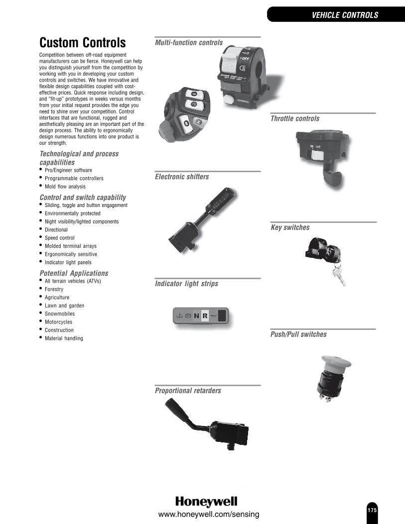
175www.honeywell.com/sensing
Custom ControlsCompetition between off-road equipmentmanufacturers can be fierce. Honeywell can helpyou distinguish yourself from the competition byworking with you in developing your customcontrols and switches. We have innovative andflexible design capabilities coupled with cost-effective prices. Quick response including design,and “fit-up” prototypes in weeks versus monthsfrom your initial request provides the edge youneed to shine over your competition. Controlinterfaces that are functional, rugged andaesthetically pleasing are an important part of thedesign process. The ability to ergonomicallydesign numerous functions into one product isour strength.
Technological and processcapabilities• Pro/Engineer software• Programmable controllers• Mold flow analysis
Control and switch capability• Sliding, toggle and button engagement• Environmentally protected• Night visibility/lighted components• Directional• Speed control• Molded terminal arrays• Ergonomically sensitive• Indicator light panels
Potential Applications• All terrain vehicles (ATVs)• Forestry• Agriculture• Lawn and garden• Snowmobiles• Motorcycles• Construction• Material handling
Multi-function controls
Electronic shifters
Throttle controls
Indicator light strips
Push/Pull switches
Key switches
CUSTOM CONTROLS
Proportional retarders
VEHICLE CONTROLS

176www.honeywell.com/sensing
HOUR METERS
Hour metersHoneywell has a wide range of hour meters that are used for recording and trackingthe total elapsed time that equipment is in use.
Long recognised as the industry leader, the Hobbs brand hour meters are designedfor use in a wide variety of potential applications and environments. In order toprotect investment in expensive equipment, our customers demand a meter that isaccurate and dependable. Down time is not an option - customers need to knowwhen it is time to service their equipment.
No matter whether the equipment is for production or recreation, manufacturers,operators and service professionals rely on Honeywell for their hour meters needs.

177www.honeywell.com/sensing
98000 SeriesLCD hour metersThe 98000 Series LCD hour meter combines reliability with a solid statepackage, built for rugged, heavy-duty applications. The meter utilizes alarge LCD display with 6 mm [0.24 in] high digits.Other benefits include shorter overall meter depth, totally silentoperation, non-volatile memory and solid-state circuitry. A wide varietyof mounting styles are offered that are direct replacements for mosttraditional hour meters. Optional offerings include, reset capability,customised logos, 4.5 Vdc to 16 Vdc, and pulse counters. The series isUL recognised and comes in a variety of mounting and case options.
Termination: 6,35 mm [¼ in] bladeSealing: IP66 (Cased hour meters only)Approvals: ULOperating temperature: -40 °C to 85 °C [-40 °F to 185 °F]Voltage range: 9 Vdc to 64 Vdc
OPTIONS
2 Screw, deluxe bezel
34,30(1.35)
22,60(0.89)
2,00(0.08) 54,10 (2.13)
35,80 (1.41)
19,10(0.75)
31,80(1.25)
3,60(0.14)
2 Screw Deluxe:Panel cutout 36,83 x 24,13 (1.45 x 0.95) rectangular opening2 x 3,81 (0.15) holes spaced 44,45 (1.750)
NUMBER OF TERMINALS CAT. LISTING2 983133 983234 with reset 98303
Rectangular, retainer mount
2,50
(0.10)
27,40(1.08)
40,60 (1.60)
34,30(1.35)
19,10(0.75)
Retainer Mount:Panel cutout 36,83 x 24,13 (1.45 x 0.95) rectangular opening
NUMBER OF TERMINALS CAT. LISTING2 983113 983214 98301
Round, 2¼ in [57,15 mm], chrome, flush cupmount
Ø57,7
(2.27)
Ø50,8
(2.00)
3,00(0.12)18,5
(0.73)
15,2(0.60)
7,60(0.30)Ø 61,2 (2.41)
Ø 50,4 (1.985)
Flush Mount (Retainer) 57,77 (2.27):Panel cutout 50,8 (2.00) Ø opening
NUMBER OF TERMINALS CAT. LISTING2 983143 983244 98304
Round, 2¼ in [57,15 mm], black, flush cup mount
Ø57,7
(2.27)
Ø50,8
(2.00)
3,00(0.12)18,5
(0.73)
15,2(0.60)
7,60(0.30)Ø 61,2 (2.41)
Ø 50,4 (1.985)
Flush Mount (Retainer) 57,77 (2.27):Panel cutout 50,8 (2.00) Ø opening
NUMBER OF TERMINALS CAT. LISTING2 983123 983224 98302
HOUR METERS

178www.honeywell.com/sensing
HOUR METERS
98000 SeriesLCD hour meter modulesThe LCD hour meter module is a custom engineered elapsed time meterdesigned to be mounted directly onto a printed circuit board (PCB). Itcan be used in a variety of dc applications that require an hour meter forpreventative maintenance, warranty verification, renting and leasing. LCDcounter also available.
Approvals: UL, CSAVoltage range: A 9 Vdc to 64 Vdc
B 4.5 Vdc to 16 Vdc
14,00(0.55)
5,90(0.23)
33,78 (1.33)
27,94 (1.10)
0,135(3.43)
20,57(0.81)
Ø 0,76 ±0,05(0.03 ±0.002)
5,84 (0.23)
Mounting surface
5,08 (0.20)
7,62(0.30)
26,03 (1.025)
15,24 (0.60)
NUMBER OF TERMINALS VOLTAGE RANGE CAT. LISTING4 A 987064 B 98707
Metal bezel 4 A 98750
CAUTIONAll meter modules have crucial components exposed. The module must besufficiently protected if used in an environment other than specified.Contact Honeywell when suitability of application is questioned.
98000 SeriesLCD volt/hour metersHoneywell Sensing and Control has introduced the LCD volt/hour meter thatcombines two important instruments in one rugged, sealed package.Honeywell volt hour meters monitor the condition of battery electricalsystems and simultaneously measure the total elapsed run time ofequipment in which they are installed. During operation, the micro-controllerbased movement will cycle the LCD display between voltage and hoursindication at a rate of fifteen seconds on for voltage and one second on fortotal hours. The high-impact polycarbonate case is sealed against dust andmoisture. Available in various bezel and mounting configurations,Honeywell’s volt/hour meters are the perfect choice for a variety ofapplications.
Termination: 6,35 mm [¼ in] bladeSealing: IP66Operating temperature: -40 °C to 85 °C [-40 °F to 185 °F]Voltage range: 7 Vdc to 19 Vdc
OPTIONS
Combination volt/hour meters2 Screw, deluxe bezel
34,30(1.35)
22,60(0.89)
2,00(0.08) 54,10 (2.13)
35,80 (1.41)
19,10(0.75)
31,80(1.25)
3,60(0.14)
2 Screw Deluxe:Panel cutout 36,83 x 24,13 (1.45 x 0.95) rectangular opening2 x 3,81 (0.15) holes spaced 44,45 (1.750)
CAT. LISTING98103
Rectangular, retainer mount
2,50
(0.10)
27,40(1.08)
40,60 (1.60)
34,30(1.35)
19,10(0.75)
Retainer Mount:Panel cutout 36,83 x 24,13 (1.45 x 0.95) rectangular opening
CAT. LISTING98101

179www.honeywell.com/sensing
98000 SeriesLCD volt/hour meters (continued)
Combination volt/hour metersRound, 2¼ in [57,15 mm], chrome, flush cupmount
Ø57,7
(2.27)
Ø50,8
(2.00)
3,00(0.12)18,5
(0.73)
15,2(0.60)
7,60(0.30)Ø 61,2 (2.41)
Ø 50,4 (1.985)
Flush Mount (Retainer) 57,77 (2.27):Panel cutout 50,8 (2.00) Ø opening
CAT. LISTING98111
Round, 2¼ in [57,15 mm], black, flush cup mount
Ø57,7
(2.27)
Ø50,8
(2.00)
3,00(0.12)18,5
(0.73)
15,2(0.60)
7,60(0.30)Ø 61,2 (2.41)
Ø 50,4 (1.985)
Flush Mount (Retainer) 57,77 (2.27):Panel cutout 50,8 (2.00) Ø opening
CAT. LISTING98102
Maintenance Meter
CAT. LISTING98202
Volt meters
The volt meter incorporates the features and benefits of the LCD volthour meter but is used for volts only. The large easy to read LCD displayprovides a digital readout of the vehicle voltage. Available in standardRound, 2-Screw and Rectangular case configurations, volt metersrequire only battery positive and ground leads for installation andoperation.
Termination: 6,35 mm [¼ in] bladeSealing: IP66Operating temperature: -40 °C to 85 °C [-40 °F to 185 °F]Voltage range: 7 Vdc to 19 Vdc
2 Screw, deluxe bezelCAT. LISTING98108
Rectangular, retainer mountCAT. LISTING98106
Round, 2¼ in [57,15 mm], chrome, flush cupmount
CAT. LISTING98110
Round, 2¼ in [57,15 mm], black, flush cup mountCAT. LISTING98109
HOUR METERS

180www.honeywell.com/sensing
HOUR METERS
85000 SeriesQuartz plus dc hour metersThe Quartz Plus Series of hour meters are aimed at providingperformance and reliability. Features include a highly reliable drivemechanism and odometer gear train combined with the accuracy ofquartz crystal timing. The totally sealed meters are UL/CSA recognizedand come in a variety of mounting styles.
Termination: 6,35 mm [¼ in] bladeSealing: IP67Approvals: UL, CSAOperating temperature: -40 °C to 85 °C [-40 °F to 185 °F]Voltage range: A 10 Vdc to 80 Vdc
B 6.5 Vdc to 16 VdcC 10 Vdc to 32 Vdc
OPTIONS
2 Screw, bezel
54,10 (2.13)
32,00(1.26)
23,88(0.94)
6,10(0.24)36,58 (1.44)
2,03(0.08)
47,50(1.87)
8,38(0.33)
2 Screw Mount:Panel cutout 36,83 x 24,13 (1.45 x 0.95) rectangular opening2 x 3,81 (0.15) holes spaced 44,45 (1.750)
VOLTAGE RANGE CAT. LISTINGA 85094B 85331
3 Screw, round
47,50(1.87)
8,38(0.33)
3 Screw Mount:Panel cutout 50,80 (2.00) Ø opening3 x 3,81 (0.15) holes equally spaced on a 64,26 (2.53) bolt circle Ø
Ø72,64(2.86)
Ø55,63(2.19)
7,11(0.28)
3,30(0.13)
Ø 50,42 (1.985)
VOLTAGE RANGE CAT. LISTINGA 85097
Rectangular, stirrup mount
6,10(0.24)
31,75(1.25)
44,70 (1.76)
2,03(0.08)
47,50(1.87)
8,38(0.33)
Rectangular Stirrup:Panel cutout 36,83 x 24,13 (1.45 x 0.95) rectangular opening
73,15(2.88)
VOLTAGE RANGE CAT. LISTINGC 85010
Rectangular, retainer mount
48,01(1.89)
55,63(2.19)
2,54(0.10)
26,16(1.03)
39,37 (1.55)
Rectangular Retainer:Panel cutout 36,83 x 24,13 (1.45 x 0.95) rectangular opening
Sealing: IP66
VOLTAGE RANGE CAT. LISTINGA 82320

181www.honeywell.com/sensing
85000 SeriesQuartz plus dc hour meters (continued)
Round, 2¼ in [57,15 mm], chrome, flush cupmount
Ø57,66(2.27)
Ø50,80(2.00)
Ø 50,42 (1.985)
8,38(0.33)
47,75(1.88)
3,05(0.12)
7,62(0.30)Ø 61,21 (2.41)
Flush Mount (Cup):Panel cutout 57,66 (2,27)50,80 (2.00) Ø opening
VOLTAGE RANGE CAT. LISTINGA 85342
Round, 2¼ in [57,15 mm], black, flush cup mount
Ø57,66(2.27)
Ø50,80(2.00)
Ø 50,42 (1.985)
8,38(0.33)
47,75(1.88)
3,05(0.12)
7,62(0.30)Ø 61,21 (2.41)
Flush Mount (Cup):Panel cutout 57,66 (2,27)50,80 (2.00) Ø opening
VOLTAGE RANGE CAT. LISTINGA 85093
82400 SeriesQuartz dc hour meters, polarity insensitive
Termination: 6,35 mm [¼ in] bladeSealing: IP66Approvals: ULOperating temperature: -40 °C to 85 °C [-40 °F to 185 °F]Voltage range: 10 Vdc to 80 Vdc
OPTIONS
2 Screw, bezel
22,6(0.89)
2,00(0.08)
54,10 (2.13)
35,8 (1.41)
31,80(1.25)
3,60(0.14)
55,60(2.19)
48,00(1.89)
CAT. LISTING82416
Rectangular, retainer mount
48,01(1.89)
55,63(2.19)
2,54(0.10)
26,16(1.03)
39,37 (1.55)
Rectangular Retainer:Panel cutout 36,83 x 24,13 (1.45 x 0.95) rectangular opening
CAT. LISTING82401
HOUR METERS

182www.honeywell.com/sensing
HOUR METERS
20000 SeriesDeluxe ac hour metersHoneywell’s 20000 Series Deluxe ac meter is a completely sealed hour meterthat utilizes a synchronous motor to drive the odometer gear train. Metersare available in a combination of mounting styles, voltages and frequenciesand are UL Listed, CSA and CE Certified.Termination: ScrewSealing: IP65Approvals: UL, CSA, CEOperating temperature: -54 °C to 68 °C [-65 °F to 154 °F]Voltage range: A 120 Vac, 60 Hz
B 240 Vac, 60 HzC 120 Vac, 50 HzD 240 Vac, 50 Hz
OPTIONS
2 Screw, bezel
64,80(2.55)
50,80(2.00)
4,20(0.165)
52,60 (2.07)
36,6 (1.44)2,70
(0.11)
25,90(1.02)
22,70(0.89)
35,5 (1.40)
2 Screw Mount:Panel cutout 36,83 x 24,13 (1.45 x 0.95) rectangular opening2 x 3,81 (0.15) holes spaced 44,45 (1.750)
VOLTAGE RANGE CAT. LISTINGA 20001B 20007C 20028D 20029
3 Screw, round
60,50(2.38)
46,50(1.83)
7,40(0.29)
Ø 50,40 (1.985)
Ø 55,60(2.19)
Ø 68,60(2.70)
3,30(0.13)
3 Screw Mount:Panel cutout 50,8 (2.00) Ø opening3 x 3,175 (0.125) holes equally spaced on 61,47 (2.42.) circle Ø
VOLTAGE RANGE CAT. LISTINGA 20017B 20019C 20016D 20018
Round, 2¼ in [57,15 mm], black, retainer mount
Ø50,42 (1.985)
7,62(0.30)
47,50(1.87)
5,33(0.21)
2,79(0.11)
Ø49,78(1.96)
Ø56,90(2.24)
CAT. LISTING82404
82400 SeriesQuartz dc hour meters, polarity insensitive(continued)

183www.honeywell.com/sensing
28000 SeriesStandard ac hour metersThe Honeywell 28000 Series ac hour meters use a synchronous motorto drive the odometer gear train. These meters can be used in a widevariety of potential applications including control panels and medicalapplications. All styles are UL, CSA and CE certified.
Termination: 6,35 mm [¼ in] bladeSealing: IP64Approvals: UL, CSA, CEOperating temperature: -54 °C to 68 °C [-65 °F to 154 °F]Voltage range: A 120 Vac, 60 Hz
B 240 Vac, 60 HzC 120 Vac, 50 HzD 240 Vac, 50 Hz
OPTIONS
Rectangular, retainer mount
48,01(1.89)
55,63(2.19)
2,54(0.10)
26,16(1.03)
39,37 (1.55)
Rectangular Retainer:Panel cutout 36,83 x 24,13 (1.45 x 0.95) rectangular opening
VOLTAGE RANGE CAT. LISTINGA 28000B 28004C 28002D 28006
Round, 2¼ in [57,15 mm], retainer mount
VOLTAGE RANGE CAT. LISTINGA 28030
HOUR METERS

184www.honeywell.com/sensing
Key Switches
KEY SWITCHES
OPTIONSScrew terminals
72,392.8539,88
1.57
Ø41,151.62
SWITCH POSITIONS CAT. LISTING2 (Off/On) 848283 (Off/On/Start) 848293 (On/Off/On) 84830
Honeywell Key switches are custom engineered, environmentally sealed,sliding contact switches. They can be designed to match existing keys or touse a six tumbler mechanism with up to 300 unique key combinations. Thestainless steel keyhole shroud and keyhole dust shutter contribute to thedurability of the assembly while O-rings protect the contact and rotorassembly from moisture and contamination.Key switches can be used in off-highway, material handling or otherpotential applications where environmental specifications must be met.They have been tested for temperature, vibration, dust, cycling,humidity, pressure wash and salt fog and mount into a 22,10 mm [0.87in] hole in panels 3,81 mm to 6,35 mm [0.15 in to 0.25 in] thick.Standard configurations are shown below, others are available. Contactyour Honeywell sales representative for more information.Mechanical life: 25000 cyclesOperating temperature: -40 °C to 85 °C
[-40 °F to 185 °F]Connector: Screw or Packard MetriPack 280 SeriesElectrical rating: Screw - 20 A, 12 Vdc
10 A, 24 Vdc4 A, 48 Vdc
Packard MetriPack - 20 A, 12 Vac8 A, 24 Vac
OFF
ON
45˚
OFF - ON
OFF START
ON45˚45˚
OFF - ON - START(Key removable in OFF position)
OFF
ON ON
45˚45˚
ON - OFF - ON(Key removable in OFF position)
2 Position 3 Position 3 Position
OFF
ON
START
PREHEAT22.5˚
22.5˚45˚
OFF - ON - PREHEAT - START(Key removable in OFF position)
4 Position
Integral connector
Ø41,151.62
74,932.9543,43
1.71
SWITCH POSITIONS CAT. LISTING2 (Off/On) 848253 (Off/On/Start) 848263 (Off/On/Start, Magneto Ground) 891654 (Off/On/Preheat/Start) 89477

185www.honeywell.com/sensing
PUSH/PULL SWITCHES
Push/Pull Switches
Honeywell’s Push/Pull switches are robust, environmentally sealed,positive action, sliding contact switches incorporating two circuits withmultiple combinations. The switch can be designed with a single contactclosure in either the push or pull position, two contact closures in eitherthe push or pull positions or a single contact closure in both the pushand pull position. For more details on these options, contact a Honeywellsales office. The dual O-ring design protects the contact chamber byisolating it from moisture or any other contaminant.These switches may be suitable for the demands of harsh environmentsfound in off-highway, material handling or other applications whererapid, positive action is required.Mechanical life: 25000 cyclesOperating temperature: -40 °C to 100 °C
[-40 °F to 212 °F]Connector: Screw TerminalsElectrical rating: 20 A, 12 to 14 Vdc
10 A, 24 VdcSealing: IP67
72,01(2.835)
28,32(1.115)
Mounting panelthickness1,27 - 4,83(0.05 - 0.19)
CIRCUITRY CAT. LISTING2NO Circuits in Push 879411NO/1NC Circuits in Push 87943

186www.honeywell.com/sensing
Shifters
SHIFTERS
Honeywell electromechanical shifters are often ideal for meeting thedirection and speed control requirements of most off-highwayapplications. They are completely sealed and are built to withstand theharsh environments of the off-highway industry.Mounting clamps for shifters and turn signals are available to orderseparately, with or without locating pin, for column sizes shown in orderguides.Standard configurations are shown below, others are available. Contact yourHoneywell sales representative for more information.
Shifter - FNRForward, Neutral, Reverse
OPTIONS
Column size 38 mm or 45 mm [1.50 in or 1.77 in]Integral Packard connectorFEATURES MOUNTING CAT. LISTINGNeutral lock left or right 80438No neutral lock left or right 81521Neutral lock/Wash/wipe right 86835
Wire harness connectorFEATURES MOUNTING CAT. LISTINGNeutral lock left 80909
Column size 55 mm [2.17 in]Integral Deutsch connectorFEATURES MOUNTING CAT. LISTINGNeutral lock/Horn left 80910
Shifter - FNRForward, Neutral, Reverse with speed selector
OPTIONS
Column size 38 mm or 45 mm [1.50 in or 1.77 in]Integral Deutsch connectorFEATURES MOUNTING SPEEDS CAT. LISTINGNeutral lock left 4 81248Neutral lock/button left 3 81426No neutral lock left 3 81758Neutral lock left bump 84105Neutral lock right 6 85874
Wire harness connectorFEATURES MOUNTING SPEEDS CAT. LISTINGNeutral lock left 4 84467
Mechanical life:Rotary 1 million cycles (2 A, 12 V load)
Shifter handle 500,000 cyclesLever with drop down neutral lock 3 million cycles
without drop down neutral lock 5 million cylesSealing: IP67Operating temperature: -40 °C to 85 °C
[-40 °F to 185 °F]Supply voltage: 3V to 32 V operation [12 V or 24 V typ.]Mounts to column size: 38 mm, 45 mm or 55 mm
[1.50 in, 1.77 in or 2.17 in]Neutral lock: Drop downConnector: Integral Packard, Integral Deutsch or Wire harness
12.5˚
12.5˚
N
F
78,79(3.102)75,46
(2.971)
6,10(0.24)
65,02(2.56)
Ø38,18
(1.503)
Ø44,45
(1.750)
Button switch handleTwist grip handle with button switch
59,18(2.33)
27,94(1.10)
220,47(8.68)
198,50(7.50)
Optional mounting clamps
COLUMN SIZE CAT. LISTING38 mm [1.50 in] 8026045 mm [1.77 in] 80262

187www.honeywell.com/sensing
PROPORTIONAL RETARDERS
Proportional Retarders
Honeywell’s Proportional Retarder is a shift-lever handle that attaches tothe steering column of a vehicle and gives an electronic pulse-width-modulated output signal that is proportional to the position of the lever.In standard mounting position, output signal has 10 % duty cycle whenlever is pulled towards operator to maximum extent. When moved awayfrom operator to its maximum travel, the lever snaps into a detentindicating the output signal now has 90 % duty cycle. The duty cyclebetween these two positions is a continuously variable function ofposition.Housed in a sealed unit with a rugged, positive locking connector, theproportional retarder has reverse voltage, short circuit and over voltageprotection.Travel: 25° maximum angle travelSupply Voltage: 9 Vdc to 32 Vdc
(12 Vdc to 24 Vdc operating system)Base Frequency: 500 Hz, ± 10 % over temperature and input voltageDuty Cycle: 10 % to 90 %, ± 5 % at limits of travelOutput Voltage: Pulse-width-modulated, 0 V to 7 V amplitudeWiring and Connection: Receptacle compatible with
positive-locking Deutsch DT06-6S connectorwith 18 AWG (minimum wiring to conform to 1E815)

188www.honeywell.com/sensing
Turn Signals
Honeywell Turn signal switches are built to complement the Honeywellshifters or can be mounted independently. A variety of potentialoperations are available such as wiper speeds, head lamp control, buttonand auto cancel options.These switches can be tailored to meet your design requirements;contact Honeywell for more information.
Mechanical life: Turn signal 50,000 cycles (8 A, 12 V load)Wiper 50,000 cycles (2 A, 12 V load)
Washer 20,000 cycles (2 A, 12 V load)Head lamp dimmer 20,000 cycles (15 A, 12 V load)
Sealing: IP67Operating temperature: -40 °C to 85 °C
[-40 °F to 185 °F]Supply voltage: 3V to 32 V operation (12 V or 24 V typ.)Mounts to column size: 38 mm, 45 mm, 55 mm
[1.50 in, 1.77 in, 2.17 in]Connector: Integral Packard, Integral Deutsch or Wire harness
78,99(3.11) 82,80
(3.26)
65,02(2.56)
Ø38,18
(1.503)
Ø55,12(2.17)
Button switch handlePlain handle
61,98(2.44)
Ø36,07(1.42)
1 2 3 4 5 6
12 11 10 9 8 7
50,8(2.00)
232,16(9.14) 230,63
(9.08)
84,07(3.31)
12.5˚
12.5˚
Turn signal
Integral Deutsch connectorFEATURES COLUMN SIZE CAT. LISTING
MM [IN]55 [2.17] 80877
Turn signal with wiper control
Integral Deutsch connectorFEATURES COLUMN SIZE WIPER CAT. LISTING
MM [IN] SPEEDSWash 38/45 [1.50/1.77] Hi/Lo 80350Wash 55 [2.17] 1 80876
Turn signal with head lamp control
OPTIONS
Integral Packard connectorFEATURES COLUMN SIZE LIGHTS CAT. LISTING
MM [IN]45 [1.77] Hazard warning 84884
Integral Deutsch connectorFEATURES COLUMN SIZE LIGHTS CAT. LISTING
MM [IN]Horn/side marker 45 [1.77] Head lamp switch/Dimmer 81705
Wire harness connectorFEATURES COLUMN SIZE LIGHTS CAT. LISTING
MM [IN]45 [1.77] Head lamp switch 79809
Turn signal with wiper and head lampcontrol
OPTIONS
Integral Deutsch connectorFEATURES COLUMN SIZE WIPER SPEEDS LIGHTS CAT. LISTING
MM [IN]Wash 45 [1.77] 1 Head lamp 81601
dimmer/Flash
Wire harness connectorFEATURES COLUMN SIZE WIPER SPEEDS LIGHTS CAT. LISTING
MM [IN]Wash 45 [1.77] 1 Dimmer/Flash 80279Wash 45 [1.77] Hi/Lo/Intermittent Dimmer 82570Wash/Horn/Auto cancel 38/45 [1.50/1.77] Hi/Lo/Intermittent Dimmer/Flash 86320Wash/Horn 45 [1.77] Hi/Lo Dimmer/Flash 86508
TURN SIGNALS
Optional mounting clamps
COLUMN SIZE CAT. LISTING38 mm [1.50 in] 8026045 mm [1.77 in] 80262
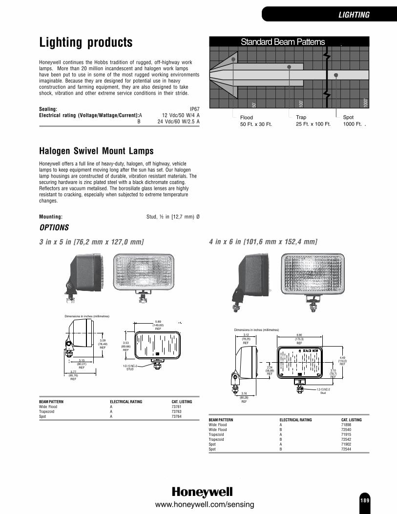
189www.honeywell.com/sensing
Lighting productsHoneywell continues the Hobbs tradition of rugged, off-highway worklamps. More than 20 million incandescent and halogen work lampshave been put to use in some of the most rugged working environmentsimaginable. Because they are designed for potential use in heavyconstruction and farming equipment, they are also designed to takeshock, vibration and other extreme service conditions in their stride.
Sealing: IP67Electrical rating (Voltage/Wattage/Current]:A 12 Vdc/50 W/4 A
B 24 Vdc/60 W/2.5 A
LIGHTING
Halogen Swivel Mount LampsHoneywell offers a full line of heavy-duty, halogen, off highway, vehiclelamps to keep equipment moving long after the sun has set. Our halogenlamp housings are constructed of durable, vibration resistant materials. Thesecuring hardware is zinc plated steel with a black dichromate coating.Reflectors are vacuum metalised. The borosiliate glass lenses are highlyresistant to cracking, especially when subjected to extreme temperaturechanges.
Mounting: Stud, ½ in [12,7 mm) Ø
OPTIONS
3 in x 5 in [76,2 mm x 127,0 mm]
3.77 REF
1/2-13 NC-2STUD
5.89(149,60)
REF
3.53(89,66)
REF
3.09(78,49)
REF
3.15(80,01)
REF3.77
(95,76)REF
Dimensions in inches (millimetres)
BEAM PATTERN ELECTRICAL RATING CAT. LISTINGWide Flood A 73761Trapezoid A 73763Spot A 73764
4 in x 6 in [101,6 mm x 152,4 mm]
1.2-13 NC-2Stud
4.49(114,0)
REF
3.10(78,7)REF
6.90(175,3)
REF
3.12(78,25)REF
3.16(80,26)
REF
2.24(56,89)
REF
Dimensions in inches (millimetres)
BEAM PATTERN ELECTRICAL RATING CAT. LISTINGWide Flood A 71898Wide Flood B 72540Trapezoid A 71915Trapezoid B 72542Spot A 71902Spot B 72544
100'
1000
'
50'
Flood50 Ft. x 30 Ft.
Trap 25 Ft. x 100 Ft.
Spot1000 Ft.
Standard Beam Patterns

190www.honeywell.com/sensing
LIGHTING
Replacement Sealed Beams
Replacement sealed beams are offered in both 3 in x 5 in [76,2 mm x127,0 mm] and 4 in x 6 in [101,6 mm x 152,4 mm] rectangular sizelenses. These are designed with the same rugged construction as theoriginals and are designed to meet the same demanding standards.These lamps are also designed to withstand tough environmentalconditions, such as sudden temperature change, shock and intensevibration.
OPTIONS
3 in x 5 in [76,2 mm x 127,0 mm]
5.89(149,61)
REF
3.53(89,66)
REF
Dimensions in inches (millimetres)
BEAM PATTERN ELECTRICAL RATING CAT. LISTINGWide Flood A 72408Trapezoid A 72801Spot A 73804
4 in x 6 in [101,6 mm x 152,4 mm]
6.90(175,26)
REF
4.49(114.05)
REF
Dimensions in inches (millimetres)
BEAM PATTERN ELECTRICAL RATING CAT. LISTINGWide Flood A 71017Wide Flood B 72541Trapezoid A 71792Trapezoid B 72543Spot A 71794Spot B 72545
Round Halogen Lamps, PAR 36
The PAR 36 Halogen work lamp may be well suited to more traditionalagricultural equipment applications. They are virtually the same 4.5 in[114,3 mm] diameter lamps that have been factory-installed on popularmakes of combines and tractors over the years.
4.5 in [114,3 mm] Ø lamp
Dimensions in inches [millimetres]5.25
(133,35)4.5
(114,30)
5.25(133,35)
BEAM PATTERN ELECTRICAL RATING CAT. LISTINGWide flood A 73468Trapezoid A 73469

191www.honeywell.com/sensing
SEALED SWITCHESLIGHTING
Portable Work Lamp
The Portable work lamp is often ideal for situations when temporarylighting is required. It can be used to replace failed equipment lighting,light dark areas, or service equipment. It is also useful for recreationalactivities.It operates by plugging the connector into a 12 Vdc cigarette lighter. Thework lamp is supplied with a 15 foot [4,92 metre] electrical cable and an80 lb [36,4 kg] magnet in the base.
3 in x 5 in [76,2 mm x 127,0 mm]with handle and switch
Dimensions in inches [millimetres]
6.00(152,40)
4.75(120,65)
3.50(88,90)
BEAM PATTERN ELECTRICAL RATING CAT. LISTINGWide flood A 80413Spot A 80510
HID XenonHigh Intensity Discharge Lamps
Honeywell Xenon high intensity discharge lamps are designed to hold upto the extreme demands of the off-highway construction and agriculturalmarkets. HID technology is significantly more efficient than halogen andproduces more light with less amperage draw.HID lamps can provide up to three times the light output compared tothe average halogen lamp. The technology allows equipment to operatemore safely with less load on the electrical system resulting in optimumalternator and battery life.Honeywell’s HID features an electronic bulb/igniter/ballast system forenhanced performance throughout a broad temperature and vibrationrange. This reduces normal failure modes including filament breakageproducing a life expectancy up to six times greater than a typical halogenlamp.
Electrical rating: 12 V [42 W] 24 V [42 W]Operating voltage range: 9 V to 16 V 10 V to 32 VStartup amperage: 15 A @ 9 V, 8 A @ 14 V,
9 A @ 16 V 5 A @ 32 VStabilised amperage: 15 A @ 9 V, 3.3 A @ 14 V,
2.7 A @ 16 V 1.4 A @ 32 VStartup time: 0.1 to 5 seconds 0.1 to 5 seconds
138,94(5.47)
138,94(5.47)
189,23(7.45)
57,15(2.25)
22,35(0.88)
146,05(5.75)
152,50 ± 19,05(6.00 ± 0.75)
to back of housing
5,08 (0.20)strip
76,96(3.03)
1/2-13 NC-2Stud
#16 GA. black wire (-)
#16 GA. red wire (+)
12 Volt (System requirement of 42 Watts]35 W D1S source
CAT. LISTINGWide flood 84760-50Spot 88217-50
24 Volt (System requirement of 42 Watts]35 W D1S source
CAT. LISTINGWide flood 88735-50Trapezoid 88913-50

192www.honeywell.com/sensing
LIGHTING
Marine Lamps
Replacement Sealed Beam
Honeywell’s marine lamps are completely weatherproof. They are totallysealed against moisture ingress, and the mounting hardware is stainlesssteel to prevent rust and corrosion. The housing is shock resistant and canwithstand up to 6 G vibration. The flood pattern illuminates an area 80° wideby 30° long.Suitable applications for Honeywell marine lamps include:• Engine compartment lighting • Shrimp and fishing boats• Deck lighting • Off-shore oil rigs• Emergency lighting • Ocean vessels• Launching and docking • Barges• Spreader lights • Dry dock lighting
• Freighters, tankers, etc.• Pleasure craft• Anywhere a corrosion resistant
lamp is needed
OPTIONS
3 in x 5 in [76,2 mm x 127,0 mm]
3.77 REF
1/2-13 NC-2STUD
5.89(149,60)
REF
3.53(89,66)
REF
3.09(78,49)
REF
3.15(80,01)
REF3.77
(95,76)REF
Dimensions in inches (millimetres)
5.89(149,61)
REF
3.53(89,66)
REF
Dimensions in inches (millimetres)
BEAM PATTERN MOUNTING ELECTRICAL LAMP REPLACEMENT SEALEDRATING CAT. LISTING BEAM CAT. LISTING
Wide Flood Stud A 73620 74041
4 in x 6 in [101,6 mm x 152,4 mm]
1.2-13 NC-2Stud
4.49(114,0)
REF
3.10(78,7)REF
6.90(175,3)
REF
3.12(78,25)REF
3.16(80,26)
REF
2.24(56,89)
REF
Dimensions in inches (millimetres)
6.90(175,26)
REF
4.49(114.05)
REF
Dimensions in inches (millimetres)
BEAM PATTERN MOUNTING ELECTRICAL LAMP REPLACEMENT SEALEDRATING CAT. LISTING BEAM CAT. LISTING
Wide flood Flush A 72656 72108Wide flood Stud A 71723 72108Wide flood Flush B 72666 72728Wide flood Stud B 72530 72728Spot Flush A 72715 72719Spot Stud A 72716 72719Spot Flush B 72717 72720Spot Stud B 72718 72720
Stud mount lamp
Replacement Sealed Beam
Stud mount lamp
3 in x 5 in lamp withspreader bracket
Flush mount lamp

193www.honeywell.com/sensing
LIGHTING
Marine HID Lamps
Honeywell’s HID marine lamps are completely weatherproof. They aretotally sealed against moisture ingress, and the mounting hardware isstainless steel to prevent rust and corrosion.
138,94(5.47)
138,94(5.47)
189,23(7.45)
57,15(2.25)
22,35(0.88)
146,05(5.75)
152,50 ± 19,05(6.00 ± 0.75)
to back of housing
5,08 (0.20)strip
76,96(3.03)
1/2-13 NC-2Stud
#16 GA. black wire (-)
#16 GA. red wire (+)
12 Volt (System requirement of 42 Watts]35 W D1S sourceBEAM PATTERN CAT. LISTINGWide flood 88432Trapezoid 89444Spot 89445
24 Volt (System requirement of 42 Watts]35 W D1S sourceBEAM PATTERN CAT. LISTINGWide flood 89446Trapezoid 89447Spot 89448
Custom Vehicle Lighting
Lighting products designed to the form, fit and functional requirementsof OEM vehicles is the fastest growing segment in lighting. Continualinvestment in the latest equipment and software allows optical designs to becreated in unique shapes and sizes to meet this need.Honeywell Product Management and Engineering personnel can offer acomplete custom design based upon the goals provided. Our manufacturingfacilities are equipped to produce such lights in a matter of weeks. Thisquick turn around for prototype and production components is aimed atmeeting even the most aggressive project timetables.

194www.honeywell.com/sensing
Pressure switches• Extensive portfolio of existing designs• Designed for transportation-related applications
(12 Vdc)• Custom designs possible• Potential applications include engine oil pressure,
compressor air pressure, heavy truck air brakepressure, transmission fluid pressure
• Modular designs
Circuit breakers• Extensive portfolio of existing designs• Designed for 12 Vdc applications• Type 1 automatic reset• Type 2 remote reset• Type 3 manual reset• Multiple designs, terminal styles, and mounting
brackets• 5 A to 50 A
Mechanical switches• Extensive portfolio of existing designs• Designed for 12 Vdc applications• Multiple designs and terminal styles• Potential applications include neutral start,
reverse lamp, and 4WD transfer case modeindication
Other VehicleControlsHoneywell Sensing and Control’s broad productand technology portfolio combined withindustry experience and application know-howoffers customers a wealth of choice:• Custom engineered solutions for application-
specific designs and product packaging• Proven technology• Low cost• Automotive grade• Extensive portfolio of designs• Extensive high-volume experience
OTHER VEHICLE CONTROLS

195www.honeywell.com/sensing
Flight control actuation• Linear and rotary flight control actuators with
integral position feedback, clutches, brakes,dual motors and other options.
• These linear actuators are typically used forhelicopter blade control. Many small aircraftuse our rotary actuators in their autopilotsystems.
Flight control position sensing• Our linear and rotary position transmitters solve
challenging measurement problems in harshenvironments.
• Added value through features such as integralgear-train and discreet switches, non-linearresponse, viewing window, auto-rig-lock feature.
Cockpit controls• Force and torque sensors integrated into flight control
linkage measure pilot input forces.• Speedbrake, flap selector, and other pilot input devices
incorporating built-in detents, servo backdrive, and upto quad-channel redundant output.
Cockpit indicators• Analog cockpit indicators serve potential applications
such as angle of attack, fuel quantity, fuel flow.• Dial, pointer and range markings can be designed to
meet almost any customer requirement.• Instruments can be either wedge lighted, backlit,
unlighted, or night vision compliant.
Pressure switches and transmitters• Pressure switches for a variety of potential
applications including engine, hydraulics, and bleed-air. Available in a wide operating range with presetdead-band.
• Our extremely rugged electromechanical pressuretransmitters operate at 250 °C [482 °F] and pressuresas high as 11,000 psi and feature ac output.
PrecisionAerospaceIf you have ever traveled by air, chances areyou’ve flown with equipment by HoneywellSensing and Control. We have been meetingdemanding aerospace applications since 1952under these brand names:• Courter• Bendix• Eclipse-Pioneer• Sperry• MICRO SWITCH• Valetin
PRECISION AEROSPACE

196www.honeywell.com/sensing
PRODUCT OVERVIEW
HONEYWELL SENSING AND CONTROL PRODUCTSSelecting the right sensor or switch for your application has never been easier. Honeywell Sensing and Control has one of the broadest product rangesof any supplier in the world, and the depth of our technology and product lines ensure you are able to find the right product for most applications.
We also have the outstanding technical support staff and responsive service to back this up, so you can always find what you need, when you need it.We aim to supply on time, every time, anywhere in the world.
Honeywell - Taking the risk and high costs out of system critical sensing and control.
You can find out more about Honeywell’s extensive product range by visiting our website at
www.honeywell.com/sensing
There you can browse our interactive catalogue and discover our full range of products for use in Industrial, Automotive, Aviation, Transportation,Motion Control, Medical applications and more. Some of our more popular product families include:
AccelerometersUtilizing Quartz Flexure and Resonating Beam technologies for inertial,control, and industrial applications.
Automotive SensorsSpeed and position sensors for engine management, wheel speed sensors,and position sensors for comfort, convenience, and motor controlapplications.
Basic SwitchesStandard size, miniature, subminiature, hermetically sealed, and hightemperature snap-action switches for applications requiring compactness,light weight, accurate repeatability and long life.
Current SensorsAdjustable linear, null balance, digital, and linear output current sensors formonitoring ac or dc current.
Electronic and Electromechanical Safety products forMachine SafeguardingSafety light curtains, laser scanners, mats, door interrupt devices and singleand multi-beam optoelectronic devices for industrial machine safety. Safetyinterlock switches, limit switches and cable-pull limit switches for industrialmachine safety. Safety control modules for industrial machine safety.
Environment Sealed Switches and SensorsDesigned for use in the harsh environments encountered in aerospace,transportation, ordnance and marine applications.
Fibre Optic SensorsActive optoelectronic components and sub-assemblies (LEDs/transmitters,fiber-DIPs, receivers and modules) for the datacom market.
Force SensorsEnhanced reliability and performance in compact commercial gradepackaging.
Hour MetersHoneywell’s Hobbs brand products are designed for elapsed timemeasurement for testing, leasing, maintenance and warranty programs.
The meter family includes LCD, Counter, Battery Controller, AC Electro-Mechanical and DC Electro-Mechanical.
Humidity SensorsRelative humidity/temperature and relative humidity sensors in chemicallyresistant packages to accommodate harsh environments.
Infrared SensorsOptoelectronic standard infrared emitting diodes (IREDs), sensors andassemblies for object presence, limit, and motion sensing, positionencoding, and movement counting.
Limit and Enclosed SwitchesHeavy duty limit switches, enclosed switches (precision snap-acting switchessealed in rugged metal housing) and sealed and explosion-proof switches.
Liquid Level SensorsBasic and industrial (designed for harsh industrial environments) liquid levelsensors used to indicate the presence or absence of liquid.
Mass Airflow SensorsAmplified and unamplified microbridge mass airflow sensors provide asensitive and fast response to the flow of air or other gas over the chip.
Off-Highway Vehicular LightingHoneywell’s Hobbs brand halogen sealed beams, composites, customdesigner lights, specialty lighting and indicator modules for vehicular andnon-vehicular applications.
Position SensorsHall-effect, magnetoresistive, and potentiometric devices for detecting thepresence of a magnetic field or linear and rotary position.

197www.honeywell.com/sensing
Pressure SensorsA wide offering of media-isolated pressure sensors with multiplepressure ports and electrical signals for a variety of potential applicationsincluding the monitoring and control of corrosive media in aggressiveenvironments.
Proximity SensorsSevere environment proximity sensors designed for use in applicationswith particularly demanding requirements on temperature, vibration,shock, and EMI/lightning resistance.
Pushbuttons, Keyswitches and IndicatorsMICRO SWITCH brand pushbuttons, keyswitches, and indicators for useanywhere manual operation is desired.
Railway Sensors and Control SystemsRailwheel proximity sensors, interface modules, train departure controlsystems, solid state sensors, pressure sensors and electromechanicalswitches for potential on-board and off-board rail industry applications.
RelaysGeneral-purpose power relays and relay sockets designed for a wide range ofapplications that require stability and reliability.
ResolversAbsolute position sensors which provides high angular accuracy, highresolution and repeatability under severe environmental conditions.
Temperature SensorsPlatinum- and silicon-based thin film resistance temperature devices (RTDs)for applications that require small package size, accuracy, and linear outputs.
Thermal ProductsBimetal thermostats, Discrete and Packaged Thermistors, Precision Hi-RelNegative Temperature Coefficient (NTC) Thermistors, Thermal cut offs andFlexible Heaters
Thermocouples, Non-contact probes and RTDsMegopak thermocouples, thermocouples with protecting tubes,Radiamatic/Rayotube Sensors, and the platinum RTD 100 Ohm.
Toggle and Rocker SwitchesMICRO SWITCH brand toggles, rockers and paddle switches for useanywhere manual operation is desired. Military grade and environmentsealed options are available.
Turbidity SensorsWash process turbidity sensors to improve product quality, minimizeingredient consumption, and reduce wastewater discharge in commercialand industrial bath applications.
Ultrasonic SensorsUltrasonic position sensors for presence/absence sensing, precision distancesensing or tracking for areas where other sensing technologies havedifficulty, such as clear or shiny objects, foggy or particle laden air, orsplashing liquids.
VRS Speed and Timing SensorsCompletely self-powered, VRS (magnetic) sensors are simple, ruggeddevices that do not require an external voltage source for operation. They aregenerally used to provide speed, timing or synchronization data to a display(or control circuitry) in the form of a pulse train.
This list of our products is not exhaustive,so check out our full range atwww.honeywell.com/sensing
PRODUCT OVERVIEW

198www.honeywell.com/sensing
New Technologiesand EmergingCapabilities
Honeywell Sensing and Control is constantly developing new technologies to keep customerscompetitive and at the forefront of their businesses. We excel at delivering innovative sensing andswitching solutions with best use of technology. We are able to combine our different sensingtechnologies to offer differentiating solutions with enhanced precision and accuracy for theincreasingly complex needs of our customers. Our range of technologies, combined with ourapplication expertise and our customization capability, is what makes our sensors and switchesleaders in their fields.
Wireless Pressure and Torque SensorsNew sensing capabilities using Surface Acoustic Wave (SAW) technology
Potential Applications• Electronic power steering
• Electro-hydraulic power steering
• Active suspension control
• Limited slip drive train controls
• Transmissions
Emissions sensorsNew sensing technologies to measure Exhaust gas recirculation (EGR) mass flow, In- cylinderpressure, oxygen, particulate matter, ammonia, nitrogen oxide.
NEW TECHNOLOGIES

199www.honeywell.com/sensing
Index101HS1 . . . . . . . . . . . . . . . . . . . . . . 129101TL1-21 . . . . . . . . . . . . . . . . . . . . 142102HS1 . . . . . . . . . . . . . . . . . . . . . . 129102TL2-2 . . . . . . . . . . . . . . . . . . . . . 141102TL2-3 . . . . . . . . . . . . . . . . . . . . . 141109HM1 . . . . . . . . . . . . . . . . . . . . . . 127111SM1 . . . . . . . . . . . . . . . . . . . . . . 106111SM2-T . . . . . . . . . . . . . . . . . . . . 106114HM1-2 . . . . . . . . . . . . . . . . . . . . 1261172CX12 . . . . . . . . . . . . . . . . . . . . . 651172CX2 . . . . . . . . . . . . . . . . . . . . . . 6511CX12 . . . . . . . . . . . . . . . . . . . . . . . 6511CX12E . . . . . . . . . . . . . . . . . . . . . . 6511CX2 . . . . . . . . . . . . . . . . . . . . . . . . 6511CX2E . . . . . . . . . . . . . . . . . . . . . . . 6511HM1 . . . . . . . . . . . . . . . . . . . . . . . 12711NT1-2 . . . . . . . . . . . . . . . . . . . . . 15111NT1-3 . . . . . . . . . . . . . . . . . . . . . 15111NT1-7 . . . . . . . . . . . . . . . . . . . . . 15211NT1-7-NH . . . . . . . . . . . . . . . . . . 15211SM1 . . . . . . . . . . . . . . . . . . . . . . . 10611SM601-H4 . . . . . . . . . . . . . . . . . . 10611SX1-T . . . . . . . . . . . . . . . . . . . . . 10611TS115-3 . . . . . . . . . . . . . . . . . . . 15611TS15-1 . . . . . . . . . . . . . . . . . . . . 15611TS15-2 . . . . . . . . . . . . . . . . . . . . 15611TS15-6 . . . . . . . . . . . . . . . . . . . . 15611TS15-7 . . . . . . . . . . . . . . . . . . . . 15611TS95-2 . . . . . . . . . . . . . . . . . . . . 15611TS95-7 . . . . . . . . . . . . . . . . . . . . 15611TW1-1L . . . . . . . . . . . . . . . . . . . . 14411TW1-2 . . . . . . . . . . . . . . . . . . . . . 14411TW1-3 . . . . . . . . . . . . . . . . . . . . . 14411TW1-3D . . . . . . . . . . . . . . . . . . . . 14411TW1-7 . . . . . . . . . . . . . . . . . . . . . 14411TW8-2 . . . . . . . . . . . . . . . . . . . . . 14411TW8-3 . . . . . . . . . . . . . . . . . . . . . 14411TW8-5 . . . . . . . . . . . . . . . . . . . . . 14411TW8-7 . . . . . . . . . . . . . . . . . . . . . 144120000 . . . . . . . . . . . . . . . . . . . . . . 116120001 . . . . . . . . . . . . . . . . . . . . . . 116120002 . . . . . . . . . . . . . . . . . . . . . . 116120003 . . . . . . . . . . . . . . . . . . . . . . 116120004 . . . . . . . . . . . . . . . . . . . . . . 116120005 . . . . . . . . . . . . . . . . . . . . . . 116120006 . . . . . . . . . . . . . . . . . . . . . . 116120007 . . . . . . . . . . . . . . . . . . . . . . 116120008 . . . . . . . . . . . . . . . . . . . . . . 11612HR1-S . . . . . . . . . . . . . . . . . . . . . 13812HR8-6 . . . . . . . . . . . . . . . . . . . . . 13812NT1-3 . . . . . . . . . . . . . . . . . . . . . 15112PA4 . . . . . . . . . . . . . . . . . . . . . . . 158
12PA5-BK . . . . . . . . . . . . . . . . . . . . 15812PA5-BL . . . . . . . . . . . . . . . . . . . . 15812PA5-G . . . . . . . . . . . . . . . . . . . . . 15812PA5-R . . . . . . . . . . . . . . . . . . . . . 15812PA5-W . . . . . . . . . . . . . . . . . . . . . 15812PA5-Y . . . . . . . . . . . . . . . . . . . . . 15812PA6 . . . . . . . . . . . . . . . . . . . . . . . 15812SE4-T . . . . . . . . . . . . . . . . . . . . . 12212TL1-2 . . . . . . . . . . . . . . . . . . . . . . 14112TL1-3 . . . . . . . . . . . . . . . . . . . . . . 14112TS115-3 . . . . . . . . . . . . . . . . . . . 15612TS15-2 . . . . . . . . . . . . . . . . . . . . 15612TS15-3 . . . . . . . . . . . . . . . . . . . . 15612TS15-7 . . . . . . . . . . . . . . . . . . . . 15612TS95-10 . . . . . . . . . . . . . . . . . . . 15612TS95-3 . . . . . . . . . . . . . . . . . . . . 15612TW1-1 . . . . . . . . . . . . . . . . . . . . . 14412TW1-3 . . . . . . . . . . . . . . . . . . . . . 14412TW1-3D . . . . . . . . . . . . . . . . . . . . 14412TW1-50 . . . . . . . . . . . . . . . . . . . . 14412TW1-50M . . . . . . . . . . . . . . . . . . 14412TW1-7 . . . . . . . . . . . . . . . . . . . . . 14412TW1-70 . . . . . . . . . . . . . . . . . . . . 14412TW29-1 . . . . . . . . . . . . . . . . . . . . 14412TW29-7 . . . . . . . . . . . . . . . . . . . . 14412TW75-3 . . . . . . . . . . . . . . . . . . . . 14412TW75-7 . . . . . . . . . . . . . . . . . . . . 14412TW8-3 . . . . . . . . . . . . . . . . . . . . . 14412TW8-7 . . . . . . . . . . . . . . . . . . . . . 14413HM1 . . . . . . . . . . . . . . . . . . . . . . . 12714CE1-1 . . . . . . . . . . . . . . . . . . . . . . 2414CE1-1A . . . . . . . . . . . . . . . . . . . . . 2414CE1-1G . . . . . . . . . . . . . . . . . . . . . 2414CE1-2 . . . . . . . . . . . . . . . . . . . . . . 2414CE1-3 . . . . . . . . . . . . . . . . . . . . . . 2414CE1-3A . . . . . . . . . . . . . . . . . . . . . 2414CE1-3G . . . . . . . . . . . . . . . . . . . . . 2414CE1-AQ . . . . . . . . . . . . . . . . . . . . . 2414CE1-Q . . . . . . . . . . . . . . . . . . . . . . 2414CE101-1 . . . . . . . . . . . . . . . . . . . . 5814CE101-10 . . . . . . . . . . . . . . . . . . . 5814CE101-2 . . . . . . . . . . . . . . . . . . . . 5814CE101-3 . . . . . . . . . . . . . . . . . . . . 5814CE101-4 . . . . . . . . . . . . . . . . . . . . 5814CE101-5 . . . . . . . . . . . . . . . . . . . . 5814CE101-6 . . . . . . . . . . . . . . . . . . . . 5814CE102-1 . . . . . . . . . . . . . . . . . . . . 5814CE102-12 . . . . . . . . . . . . . . . . . . . 5814CE102-15 . . . . . . . . . . . . . . . . . . . 5814CE102-3 . . . . . . . . . . . . . . . . . . . . 5814CE102-3G . . . . . . . . . . . . . . . . . . . 5814CE102-5 . . . . . . . . . . . . . . . . . . . . 5814CE102-6 . . . . . . . . . . . . . . . . . . . . 5814CE102-6G . . . . . . . . . . . . . . . . . . . 5814CE102-8 . . . . . . . . . . . . . . . . . . . . 5814CE103-1 . . . . . . . . . . . . . . . . . . . . 58
14CE103-3 . . . . . . . . . . . . . . . . . . . . 5814CE118-1 . . . . . . . . . . . . . . . . . . . . 5814CE118-10 . . . . . . . . . . . . . . . . . . . 5814CE118-6 . . . . . . . . . . . . . . . . . . . . 5814CE16-1 . . . . . . . . . . . . . . . . . . . . . 2514CE16-2 . . . . . . . . . . . . . . . . . . . . . 2514CE16-3 . . . . . . . . . . . . . . . . . . . . . 2514CE18-1 . . . . . . . . . . . . . . . . . . . . . 2414CE18-3 . . . . . . . . . . . . . . . . . . . . . 2414CE18-Q . . . . . . . . . . . . . . . . . . . . . 2414CE2-1 . . . . . . . . . . . . . . . . . . . . . . 2414CE2-1A . . . . . . . . . . . . . . . . . . . . . 2414CE2-1G . . . . . . . . . . . . . . . . . . . . . 2414CE2-2 . . . . . . . . . . . . . . . . . . . . . . 2414CE2-2A . . . . . . . . . . . . . . . . . . . . . 2414CE2-3 . . . . . . . . . . . . . . . . . . . . . . 2414CE2-3A . . . . . . . . . . . . . . . . . . . . . 2414CE2-3G . . . . . . . . . . . . . . . . . . . . . 2414CE2-AQ . . . . . . . . . . . . . . . . . . . . . 2414CE2-Q . . . . . . . . . . . . . . . . . . . . . . 2414CE20-1 . . . . . . . . . . . . . . . . . . . . . 2514CE20-3 . . . . . . . . . . . . . . . . . . . . . 2514CE3-1 . . . . . . . . . . . . . . . . . . . . . . 2514CE3-2 . . . . . . . . . . . . . . . . . . . . . . 2514CE3-3 . . . . . . . . . . . . . . . . . . . . . . 2514CE31-1 . . . . . . . . . . . . . . . . . . . . . 2414CE31-3 . . . . . . . . . . . . . . . . . . . . . 2414CE66-1 . . . . . . . . . . . . . . . . . . . . . 2414CE66-2 . . . . . . . . . . . . . . . . . . . . . 2414NT1-3 . . . . . . . . . . . . . . . . . . . . . 15114XE1 . . . . . . . . . . . . . . . . . . . . . . . 12414XE1-T . . . . . . . . . . . . . . . . . . . . . 12415HM2 . . . . . . . . . . . . . . . . . . . . . . . 12715HM5 . . . . . . . . . . . . . . . . . . . . . . . 12716CX12 . . . . . . . . . . . . . . . . . . . . . . . 6516CX2 . . . . . . . . . . . . . . . . . . . . . . . . 6518CX0 . . . . . . . . . . . . . . . . . . . . . . . . 6518CX10 . . . . . . . . . . . . . . . . . . . . . . . 6518CX10E . . . . . . . . . . . . . . . . . . . . . . 6519HM1 . . . . . . . . . . . . . . . . . . . . . . . 12719HM4 . . . . . . . . . . . . . . . . . . . . . . . 12719PA137-HM . . . . . . . . . . . . . . . . . . 1271CPSA1 . . . . . . . . . . . . . . . . . . . . . . 1001CPSA1A . . . . . . . . . . . . . . . . . . . . 1001CPSA1B . . . . . . . . . . . . . . . . . . . . 1001CPSA2 . . . . . . . . . . . . . . . . . . . . . . 1001CPSA2A . . . . . . . . . . . . . . . . . . . . 1001CPSA2B . . . . . . . . . . . . . . . . . . . . 1001CPSA3 . . . . . . . . . . . . . . . . . . . . . . 1001CPSA3A . . . . . . . . . . . . . . . . . . . . 1001CPSA3B . . . . . . . . . . . . . . . . . . . . 1001CPSA4 . . . . . . . . . . . . . . . . . . . . . . 1001CPSA5 . . . . . . . . . . . . . . . . . . . . . . 1001CPSA6 . . . . . . . . . . . . . . . . . . . . . . 1001CPSA6A . . . . . . . . . . . . . . . . . . . . 1001CPSA6B . . . . . . . . . . . . . . . . . . . . 100
INDEX

200www.honeywell.com/sensing
1CPSA7 . . . . . . . . . . . . . . . . . . . . . . 1001CPSA8 . . . . . . . . . . . . . . . . . . . . . . 1001CPSC1 . . . . . . . . . . . . . . . . . . . . . . 1001CPSC1A . . . . . . . . . . . . . . . . . . . . 1001CPSC2 . . . . . . . . . . . . . . . . . . . . . . 1001CPSC2A . . . . . . . . . . . . . . . . . . . . 1001CPSC2B . . . . . . . . . . . . . . . . . . . . 1001CPSC3 . . . . . . . . . . . . . . . . . . . . . . 1001CPSC3A . . . . . . . . . . . . . . . . . . . . 1001CPSC4 . . . . . . . . . . . . . . . . . . . . . . 1001CPSC5 . . . . . . . . . . . . . . . . . . . . . . 1001CPSC6 . . . . . . . . . . . . . . . . . . . . . . 1001CPSC6A . . . . . . . . . . . . . . . . . . . . 1001CPSC7 . . . . . . . . . . . . . . . . . . . . . . 1001CPSC8 . . . . . . . . . . . . . . . . . . . . . . 1001EN1-6 . . . . . . . . . . . . . . . . . . . . . . 1331EN231-6 . . . . . . . . . . . . . . . . . . . . 1331EN51-6 . . . . . . . . . . . . . . . . . . . . . 1331EN61-6 . . . . . . . . . . . . . . . . . . . . . 1331EN75-R . . . . . . . . . . . . . . . . . . . . . 1341EN75-R3 . . . . . . . . . . . . . . . . . . . . 1341EN76-R . . . . . . . . . . . . . . . . . . . . . 1341EX1 . . . . . . . . . . . . . . . . . . . . . . . . . 611HE1-6 . . . . . . . . . . . . . . . . . . . . . . 1371HE222-6 . . . . . . . . . . . . . . . . . . . . 1371HS1 . . . . . . . . . . . . . . . . . . . . . . . . 1291HS3 . . . . . . . . . . . . . . . . . . . . . . . . 1281HS41 . . . . . . . . . . . . . . . . . . . . . . . 1291HS6 . . . . . . . . . . . . . . . . . . . . . . . . 1291HT1 . . . . . . . . . . . . . . . . . . . . . . . . 1301LS1 . . . . . . . . . . . . . . . . . . . . . . . . . 301LS1-4C . . . . . . . . . . . . . . . . . . . . . . 301LS1-L . . . . . . . . . . . . . . . . . . . . . . . 301LS10 . . . . . . . . . . . . . . . . . . . . . . . . 311LS10-4C . . . . . . . . . . . . . . . . . . . . . 311LS10-L . . . . . . . . . . . . . . . . . . . . . . 311LS131 . . . . . . . . . . . . . . . . . . . . . . . 301LS19 . . . . . . . . . . . . . . . . . . . . . . . . 301LS19-4C . . . . . . . . . . . . . . . . . . . . . 301LS2 . . . . . . . . . . . . . . . . . . . . . . . . . 311LS2-4C . . . . . . . . . . . . . . . . . . . . . . 311LS2-L . . . . . . . . . . . . . . . . . . . . . . . 311LS23 . . . . . . . . . . . . . . . . . . . . . . . . 311LS243 . . . . . . . . . . . . . . . . . . . . . . . 301LS243-4C . . . . . . . . . . . . . . . . . . . . 301LS3 . . . . . . . . . . . . . . . . . . . . . . . . . 301LS3-4C . . . . . . . . . . . . . . . . . . . . . . 301LS3-L . . . . . . . . . . . . . . . . . . . . . . . 301LS47 . . . . . . . . . . . . . . . . . . . . . . . . 311LS501 . . . . . . . . . . . . . . . . . . . . . . . 301LS53 . . . . . . . . . . . . . . . . . . . . . . . . 311LS56 . . . . . . . . . . . . . . . . . . . . . . . . 311LS58 . . . . . . . . . . . . . . . . . . . . . . . . 301LS59 . . . . . . . . . . . . . . . . . . . . . . . . 301LS6 . . . . . . . . . . . . . . . . . . . . . . . . . 301LS9 . . . . . . . . . . . . . . . . . . . . . . . . . 31
1NT1-1 . . . . . . . . . . . . . . . . . . . . . . 1521NT1-2 . . . . . . . . . . . . . . . . . . . . . . 1511NT1-2G . . . . . . . . . . . . . . . . . . . . . 1511NT1-3 . . . . . . . . . . . . . . . . . . . . . . 1511NT1-3-NH . . . . . . . . . . . . . . . . . . . 1511NT1-3D . . . . . . . . . . . . . . . . . . . . . 1511NT1-5 . . . . . . . . . . . . . . . . . . . . . . 1521NT1-6 . . . . . . . . . . . . . . . . . . . . . . 1511NT1-7 . . . . . . . . . . . . . . . . . . . . . . 1521NT1-7-NH . . . . . . . . . . . . . . . . . . . 1521NT1-7E . . . . . . . . . . . . . . . . . . . . . 1521NT1-8 . . . . . . . . . . . . . . . . . . . . . . 1511NT1-8-NH . . . . . . . . . . . . . . . . . . . 1511NT20-7E . . . . . . . . . . . . . . . . . . . . 1521NT231-7 . . . . . . . . . . . . . . . . . . . . 1521NT91-2 . . . . . . . . . . . . . . . . . . . . . 1511NT91-7 . . . . . . . . . . . . . . . . . . . . . 1521SE1 . . . . . . . . . . . . . . . . . . . . . . . . 1221SE1-T . . . . . . . . . . . . . . . . . . . . . . 1221SE2 . . . . . . . . . . . . . . . . . . . . . . . . 1221SE3 . . . . . . . . . . . . . . . . . . . . . . . . 1221SE61-T . . . . . . . . . . . . . . . . . . . . . 1221SE7 . . . . . . . . . . . . . . . . . . . . . . . . 1221SX1-T . . . . . . . . . . . . . . . . . . . . . . 1061TB1-2 . . . . . . . . . . . . . . . . . . . . . . 1051TL1-1 . . . . . . . . . . . . . . . . . . . . . . . 1421TL1-1A . . . . . . . . . . . . . . . . . . . . . 1421TL1-2 . . . . . . . . . . . . . . . . . . . . . . . 1411TL1-21 . . . . . . . . . . . . . . . . . . . . . . 1421TL1-2D . . . . . . . . . . . . . . . . . . . . . 1411TL1-2G . . . . . . . . . . . . . . . . . . . . . 1411TL1-3 . . . . . . . . . . . . . . . . . . . . . . . 1411TL1-3D . . . . . . . . . . . . . . . . . . . . . 1411TL1-5 . . . . . . . . . . . . . . . . . . . . . . . 1421TL1-6 . . . . . . . . . . . . . . . . . . . . . . . 1411TL1-61 . . . . . . . . . . . . . . . . . . . . . . 1421TL1-7 . . . . . . . . . . . . . . . . . . . . . . . 1421TL1-7E . . . . . . . . . . . . . . . . . . . . . . 1421TL1-8 . . . . . . . . . . . . . . . . . . . . . . . 1411TL1-8F . . . . . . . . . . . . . . . . . . . . . . 1411TL150-3D . . . . . . . . . . . . . . . . . . . 1411TP1-6 . . . . . . . . . . . . . . . . . . . . . . 1581TP12-7 . . . . . . . . . . . . . . . . . . . . . 1581TP201-7 . . . . . . . . . . . . . . . . . . . . 1581TP8-2 . . . . . . . . . . . . . . . . . . . . . . 1581TP8-3 . . . . . . . . . . . . . . . . . . . . . . 1581TP8-7 . . . . . . . . . . . . . . . . . . . . . . 1581TW1-3 . . . . . . . . . . . . . . . . . . . . . . 1441XE1 . . . . . . . . . . . . . . . . . . . . . . . . 1241XE1-T . . . . . . . . . . . . . . . . . . . . . . 1241XE201 . . . . . . . . . . . . . . . . . . . . . . 1241XE3 . . . . . . . . . . . . . . . . . . . . . . . . 1241XE301 . . . . . . . . . . . . . . . . . . . . . . 1241XE401-6 . . . . . . . . . . . . . . . . . . . . 1241XE401-T . . . . . . . . . . . . . . . . . . . . 1241XE99-T . . . . . . . . . . . . . . . . . . . . . 124
20001 . . . . . . . . . . . . . . . . . . . . . . . 18220007 . . . . . . . . . . . . . . . . . . . . . . . 18220016 . . . . . . . . . . . . . . . . . . . . . . . 18220017 . . . . . . . . . . . . . . . . . . . . . . . 18220018 . . . . . . . . . . . . . . . . . . . . . . . 18220019 . . . . . . . . . . . . . . . . . . . . . . . 1822001EN1-6 . . . . . . . . . . . . . . . . . . . 13420028 . . . . . . . . . . . . . . . . . . . . . . . 18220029 . . . . . . . . . . . . . . . . . . . . . . . 18220HM1-1 . . . . . . . . . . . . . . . . . . . . . 12621CX14 . . . . . . . . . . . . . . . . . . . . . . . 6521CX4 . . . . . . . . . . . . . . . . . . . . . . . . 6521EN75-R1 . . . . . . . . . . . . . . . . . . . 13421EN9-6 . . . . . . . . . . . . . . . . . . . . . 13422HR1-S . . . . . . . . . . . . . . . . . . . . . 13824CE1-S12B . . . . . . . . . . . . . . . . . . . 2724CE1-S2 . . . . . . . . . . . . . . . . . . . . . 2724CE1-S2A . . . . . . . . . . . . . . . . . . . . 2724CE1-S2B . . . . . . . . . . . . . . . . . . . . 2724CE1-S3 . . . . . . . . . . . . . . . . . . . . . 2724CE1-S6 . . . . . . . . . . . . . . . . . . . . . 2724CE1-Y1A . . . . . . . . . . . . . . . . . . . . 2724CE1-Y2 . . . . . . . . . . . . . . . . . . . . . 2724CE1-Y3 . . . . . . . . . . . . . . . . . . . . . 2724CE16-S1 . . . . . . . . . . . . . . . . . . . . 2724CE16-Y1 . . . . . . . . . . . . . . . . . . . . 2724CE16-Y6 . . . . . . . . . . . . . . . . . . . . 2724CE2-S1 . . . . . . . . . . . . . . . . . . . . . 2724CE2-S2 . . . . . . . . . . . . . . . . . . . . . 2724CE2-S2A . . . . . . . . . . . . . . . . . . . . 2724CE2-S2B . . . . . . . . . . . . . . . . . . . . 2724CE2-S3 . . . . . . . . . . . . . . . . . . . . . 2724CE2-S6 . . . . . . . . . . . . . . . . . . . . . 2724CE2-T2 . . . . . . . . . . . . . . . . . . . . . 2724CE2-Y1 . . . . . . . . . . . . . . . . . . . . . 2724CE2-Y2 . . . . . . . . . . . . . . . . . . . . . 2724CE2-Y2A . . . . . . . . . . . . . . . . . . . . 2724CE2-Y4 . . . . . . . . . . . . . . . . . . . . . 2724CE2-Y6A . . . . . . . . . . . . . . . . . . . . 2724CE28-S2 . . . . . . . . . . . . . . . . . . . . 2824CE3-S2 . . . . . . . . . . . . . . . . . . . . . 2824CE3-Y1 . . . . . . . . . . . . . . . . . . . . . 2824CE3-Y2 . . . . . . . . . . . . . . . . . . . . . 2824CE31-S1 . . . . . . . . . . . . . . . . . . . . 2824CE31-S2 . . . . . . . . . . . . . . . . . . . . 2824CE31-S2B . . . . . . . . . . . . . . . . . . . 2824CE31-S5 . . . . . . . . . . . . . . . . . . . . 2824CE31-Y1 . . . . . . . . . . . . . . . . . . . . 2824CE31-Y2 . . . . . . . . . . . . . . . . . . . . 2824CE31-Y3 . . . . . . . . . . . . . . . . . . . . 2824CE55-S1 . . . . . . . . . . . . . . . . . . . . 2824CE55-S2 . . . . . . . . . . . . . . . . . . . . 2824CE55-Y1 . . . . . . . . . . . . . . . . . . . . 2824CX12 . . . . . . . . . . . . . . . . . . . . . . . 6524CX2 . . . . . . . . . . . . . . . . . . . . . . . . 6525ET1-T-F . . . . . . . . . . . . . . . . . . . . 148
INDEX

201www.honeywell.com/sensing
25ET117-T . . . . . . . . . . . . . . . . . . . . 14825ET61-6 . . . . . . . . . . . . . . . . . . . . . 14825ET61-S . . . . . . . . . . . . . . . . . . . . 14825ET61-S-F . . . . . . . . . . . . . . . . . . . 14825ET61-T . . . . . . . . . . . . . . . . . . . . . 14825ET62-6 . . . . . . . . . . . . . . . . . . . . . 14825ET64-6 . . . . . . . . . . . . . . . . . . . . . 14826900 . . . . . . . . . . . . . . . . . . . . . . . 11726901 . . . . . . . . . . . . . . . . . . . . . . . 11726902 . . . . . . . . . . . . . . . . . . . . . . . 11726903 . . . . . . . . . . . . . . . . . . . . . . . 11726904 . . . . . . . . . . . . . . . . . . . . . . . 11726905 . . . . . . . . . . . . . . . . . . . . . . . 11726906 . . . . . . . . . . . . . . . . . . . . . . . 11726907 . . . . . . . . . . . . . . . . . . . . . . . 11726908 . . . . . . . . . . . . . . . . . . . . . . . 11726909 . . . . . . . . . . . . . . . . . . . . . . . 11726911 . . . . . . . . . . . . . . . . . . . . . . . 11726912 . . . . . . . . . . . . . . . . . . . . . . . 11726913 . . . . . . . . . . . . . . . . . . . . . . . 11726914 . . . . . . . . . . . . . . . . . . . . . . . 11726CX4 . . . . . . . . . . . . . . . . . . . . . . . . 6526ET1-R-F . . . . . . . . . . . . . . . . . . . . 14826ET1-T-F . . . . . . . . . . . . . . . . . . . . 14826ET107-T . . . . . . . . . . . . . . . . . . . . 14826ET61-T . . . . . . . . . . . . . . . . . . . . . 14826ET65-T . . . . . . . . . . . . . . . . . . . . . 14827ET118-T2-N . . . . . . . . . . . . . . . . . 14827ET2-6-E . . . . . . . . . . . . . . . . . . . . 14827ET61-T . . . . . . . . . . . . . . . . . . . . . 14827ET61-T-E . . . . . . . . . . . . . . . . . . . 14827ET71-T . . . . . . . . . . . . . . . . . . . . . 14827ET71-T-E . . . . . . . . . . . . . . . . . . . 14828000 . . . . . . . . . . . . . . . . . . . . . . . 18328002 . . . . . . . . . . . . . . . . . . . . . . . 18328004 . . . . . . . . . . . . . . . . . . . . . . . 18328006 . . . . . . . . . . . . . . . . . . . . . . . 18328030 . . . . . . . . . . . . . . . . . . . . . . . 183281CX12 . . . . . . . . . . . . . . . . . . . . . . 65281CX2 . . . . . . . . . . . . . . . . . . . . . . . 6529ET3 . . . . . . . . . . . . . . . . . . . . . . . 1482CPSA1A1 . . . . . . . . . . . . . . . . . . . 1012CPSA1A1A . . . . . . . . . . . . . . . . . . 1012CPSA1A1B . . . . . . . . . . . . . . . . . . 1012CPSA1A2 . . . . . . . . . . . . . . . . . . . 1012CPSA1A2A . . . . . . . . . . . . . . . . . . 1012CPSA1A2B . . . . . . . . . . . . . . . . . . 1012CPSA1A3 . . . . . . . . . . . . . . . . . . . 1012CPSA1A3A . . . . . . . . . . . . . . . . . . 1012CPSA1A3B . . . . . . . . . . . . . . . . . . 1012CPSA1B1 . . . . . . . . . . . . . . . . . . . 1012CPSA1B1A . . . . . . . . . . . . . . . . . . 1012CPSA1B1B . . . . . . . . . . . . . . . . . . 1012CPSA1B2 . . . . . . . . . . . . . . . . . . . 1012CPSA1B2A . . . . . . . . . . . . . . . . . . 1012CPSA1B2B . . . . . . . . . . . . . . . . . . 101
2CPSA1B3 . . . . . . . . . . . . . . . . . . . 1012CPSA1B3A . . . . . . . . . . . . . . . . . . 1012CPSA1B3B . . . . . . . . . . . . . . . . . . 1012CPSA2A1 . . . . . . . . . . . . . . . . . . . 1012CPSA2A1A . . . . . . . . . . . . . . . . . . 1012CPSA2A1B . . . . . . . . . . . . . . . . . . 1012CPSA2A2 . . . . . . . . . . . . . . . . . . . 1012CPSA2A2A . . . . . . . . . . . . . . . . . . 1012CPSA2A2B . . . . . . . . . . . . . . . . . . 1012CPSA2A3 . . . . . . . . . . . . . . . . . . . 1012CPSA2A3A . . . . . . . . . . . . . . . . . . 1012CPSA2A3B . . . . . . . . . . . . . . . . . . 1012CPSA2B1 . . . . . . . . . . . . . . . . . . . 1012CPSA2B1A . . . . . . . . . . . . . . . . . . 1012CPSA2B1B . . . . . . . . . . . . . . . . . . 1012CPSC1A1 . . . . . . . . . . . . . . . . . . . 1012CPSC1A1A . . . . . . . . . . . . . . . . . . 1012CPSC1A2 . . . . . . . . . . . . . . . . . . . 1012CPSC1A2A . . . . . . . . . . . . . . . . . . 1012CPSC1A3 . . . . . . . . . . . . . . . . . . . 1012CPSC1A3A . . . . . . . . . . . . . . . . . . 1012CPSC1D1A . . . . . . . . . . . . . . . . . . 1012EN1-6 . . . . . . . . . . . . . . . . . . . . . . 1332EX1 . . . . . . . . . . . . . . . . . . . . . . . . . 612HM19-1 . . . . . . . . . . . . . . . . . . . . . 1262HM19-5 . . . . . . . . . . . . . . . . . . . . . 1262HT1 . . . . . . . . . . . . . . . . . . . . . . . . 1302LS1 . . . . . . . . . . . . . . . . . . . . . . . . . 322LS1-4C . . . . . . . . . . . . . . . . . . . . . . 322LS1-L . . . . . . . . . . . . . . . . . . . . . . . 322LS111 . . . . . . . . . . . . . . . . . . . . . . . 322NT1-1 . . . . . . . . . . . . . . . . . . . . . . 1522NT1-1-NH . . . . . . . . . . . . . . . . . . . 1522NT1-10 . . . . . . . . . . . . . . . . . . . . . 1522NT1-2 . . . . . . . . . . . . . . . . . . . . . . 1512NT1-3 . . . . . . . . . . . . . . . . . . . . . . 1512NT1-3-NH . . . . . . . . . . . . . . . . . . . 1512NT1-5 . . . . . . . . . . . . . . . . . . . . . . 1522NT1-50 . . . . . . . . . . . . . . . . . . . . . 1522NT1-7 . . . . . . . . . . . . . . . . . . . . . . 1522NT1-7-NH . . . . . . . . . . . . . . . . . . . 1522NT1-70 . . . . . . . . . . . . . . . . . . . . . 1522NT1-8 . . . . . . . . . . . . . . . . . . . . . . 1512NT1-8-NH . . . . . . . . . . . . . . . . . . . 1512NT231-7 . . . . . . . . . . . . . . . . . . . . 1522NT889-70 . . . . . . . . . . . . . . . . . . . 1522NT91-7 . . . . . . . . . . . . . . . . . . . . . 1522TL1-1 . . . . . . . . . . . . . . . . . . . . . . . 1422TL1-10 . . . . . . . . . . . . . . . . . . . . . . 1422TL1-10A . . . . . . . . . . . . . . . . . . . . 1422TL1-12 . . . . . . . . . . . . . . . . . . . . . . 1422TL1-1A . . . . . . . . . . . . . . . . . . . . . 1422TL1-2 . . . . . . . . . . . . . . . . . . . . . . . 1412TL1-21 . . . . . . . . . . . . . . . . . . . . . . 1422TL1-2D . . . . . . . . . . . . . . . . . . . . . 1412TL1-3 . . . . . . . . . . . . . . . . . . . . . . . 142
2TL1-31K . . . . . . . . . . . . . . . . . . . . 1422TL1-3D . . . . . . . . . . . . . . . . . . . . . 1422TL1-3G . . . . . . . . . . . . . . . . . . . . . 1422TL1-5 . . . . . . . . . . . . . . . . . . . . . . . 1422TL1-50 . . . . . . . . . . . . . . . . . . . . . . 1422TL1-56 . . . . . . . . . . . . . . . . . . . . . . 1422TL1-6 . . . . . . . . . . . . . . . . . . . . . . . 1412TL1-7 . . . . . . . . . . . . . . . . . . . . . . . 1422TL1-70 . . . . . . . . . . . . . . . . . . . . . . 1422TL1-70E . . . . . . . . . . . . . . . . . . . . . 1422TL1-8 . . . . . . . . . . . . . . . . . . . . . . . 1422TL1-8F . . . . . . . . . . . . . . . . . . . . . . 1422TP1-7 . . . . . . . . . . . . . . . . . . . . . . 1582TP12-7 . . . . . . . . . . . . . . . . . . . . . 1582TP216-7 . . . . . . . . . . . . . . . . . . . . 1582TP216-8 . . . . . . . . . . . . . . . . . . . . 1582TP7-3 . . . . . . . . . . . . . . . . . . . . . . 158311SX5-T . . . . . . . . . . . . . . . . . . . . 10631EN1-6 . . . . . . . . . . . . . . . . . . . . . 13531EN11-6 . . . . . . . . . . . . . . . . . . . . 13531NT91-1 . . . . . . . . . . . . . . . . . . . . 15431NT91-2 . . . . . . . . . . . . . . . . . . . . 15331NT91-3 . . . . . . . . . . . . . . . . . . . . 15331NT91-6 . . . . . . . . . . . . . . . . . . . . 15331NT91-7 . . . . . . . . . . . . . . . . . . . . 15432EN1-6 . . . . . . . . . . . . . . . . . . . . . 13532EN11-6 . . . . . . . . . . . . . . . . . . . . 13532NT291-3G . . . . . . . . . . . . . . . . . . 15332NT291-5E . . . . . . . . . . . . . . . . . . 15432NT91-1 . . . . . . . . . . . . . . . . . . . . 15432NT91-2 . . . . . . . . . . . . . . . . . . . . 15332NT91-3 . . . . . . . . . . . . . . . . . . . . 15332NT91-7 . . . . . . . . . . . . . . . . . . . . 15432NT91-7-NH . . . . . . . . . . . . . . . . . 15432NT94-70L . . . . . . . . . . . . . . . . . . 15433EN1-6 . . . . . . . . . . . . . . . . . . . . . 13533EN11-6 . . . . . . . . . . . . . . . . . . . . 13534EN1-6 . . . . . . . . . . . . . . . . . . . . . 13534EN11-6 . . . . . . . . . . . . . . . . . . . . 1353EN1-6 . . . . . . . . . . . . . . . . . . . . . . 1333HT1 . . . . . . . . . . . . . . . . . . . . . . . . 1303LS1 . . . . . . . . . . . . . . . . . . . . . . . . . 323LS1-4C . . . . . . . . . . . . . . . . . . . . . . 32402EN1-6 . . . . . . . . . . . . . . . . . . . . 136404EN1-6 . . . . . . . . . . . . . . . . . . . . 13641EN1-6 . . . . . . . . . . . . . . . . . . . . . 13542EN1-6 . . . . . . . . . . . . . . . . . . . . . 13544EN1-6 . . . . . . . . . . . . . . . . . . . . . 1354EN1-6 . . . . . . . . . . . . . . . . . . . . . . 1334EX1-3 . . . . . . . . . . . . . . . . . . . . . . . 614HS4-118 . . . . . . . . . . . . . . . . . . . . 1294LS1 . . . . . . . . . . . . . . . . . . . . . . . . . 324LS1-4C . . . . . . . . . . . . . . . . . . . . . . 324NT1-1 . . . . . . . . . . . . . . . . . . . . . . 1524NT1-1A . . . . . . . . . . . . . . . . . . . . . 1524NT1-3 . . . . . . . . . . . . . . . . . . . . . . 151
INDEX

202www.honeywell.com/sensing
4SE1 . . . . . . . . . . . . . . . . . . . . . . . . 1224TL1-2 . . . . . . . . . . . . . . . . . . . . . . . 1414TL1-3 . . . . . . . . . . . . . . . . . . . . . . . 1414TL1-3D . . . . . . . . . . . . . . . . . . . . . 1414TL1-7 . . . . . . . . . . . . . . . . . . . . . . . 1424TL1-8 . . . . . . . . . . . . . . . . . . . . . . . 1414XE1 . . . . . . . . . . . . . . . . . . . . . . . . 1245LS1 . . . . . . . . . . . . . . . . . . . . . . . . . 325LS1-4C . . . . . . . . . . . . . . . . . . . . . . 325LS1-L . . . . . . . . . . . . . . . . . . . . . . . 325SE1 . . . . . . . . . . . . . . . . . . . . . . . . 1225XE1 . . . . . . . . . . . . . . . . . . . . . . . . 124602EN1-6 . . . . . . . . . . . . . . . . . . . . 136602EN222-6 . . . . . . . . . . . . . . . . . . 136602HE1-6 . . . . . . . . . . . . . . . . . . . . 137602HE106-6 . . . . . . . . . . . . . . . . . . 137604EN1-6 . . . . . . . . . . . . . . . . . . . . 136604EN222-6 . . . . . . . . . . . . . . . . . . 136604HE1-6 . . . . . . . . . . . . . . . . . . . . 13761NT1-7 . . . . . . . . . . . . . . . . . . . . . 152622EN1-6 . . . . . . . . . . . . . . . . . . . . 136622EN222-6 . . . . . . . . . . . . . . . . . . 136622HE1-6 . . . . . . . . . . . . . . . . . . . . 137624EN1-6 . . . . . . . . . . . . . . . . . . . . 136624EN222-6 . . . . . . . . . . . . . . . . . . 136624HE1-6 . . . . . . . . . . . . . . . . . . . . 13764AT22-3 . . . . . . . . . . . . . . . . . . . . . 14664AT34-7E . . . . . . . . . . . . . . . . . . . . 1466AT124-T . . . . . . . . . . . . . . . . . . . . . 1466HM1-1 . . . . . . . . . . . . . . . . . . . . . . 1266LS1 . . . . . . . . . . . . . . . . . . . . . . . . . 316LS1-4C . . . . . . . . . . . . . . . . . . . . . . 316LS2 . . . . . . . . . . . . . . . . . . . . . . . . . 316LS2-L . . . . . . . . . . . . . . . . . . . . . . . 316LS3 . . . . . . . . . . . . . . . . . . . . . . . . . 316PA102 . . . . . . . . . . . . . . . . . . . . . . . 726PA127-EX . . . . . . . . . . . . . . . . . . . . 726PA130-EX . . . . . . . . . . . . . . . . . . . . 726PA131-EX . . . . . . . . . . . . . . . . . . . . 726PA136-EX . . . . . . . . . . . . . . . . . . . . 726PA138-EX . . . . . . . . . . . . . . . . . . . . 726PA142-EX . . . . . . . . . . . . . . . . . . . . 726PA144 . . . . . . . . . . . . . . . . . . . . . . . 726PA204-EX . . . . . . . . . . . . . . . . . . . . 726PA5-EX . . . . . . . . . . . . . . . . . . . . . . 726PA57 . . . . . . . . . . . . . . . . . . . . . . . . 736PA63 . . . . . . . . . . . . . . . . . . . . . . . . 726PA69 . . . . . . . . . . . . . . . . . . . . . . . . 726PA80 . . . . . . . . . . . . . . . . . . . . . . . . 726PA82 . . . . . . . . . . . . . . . . . . . . . . . . 726SX7-T . . . . . . . . . . . . . . . . . . . . . . 10671017 . . . . . . . . . . . . . . . . . . . . . . . 19071723 . . . . . . . . . . . . . . . . . . . . . . . 19271792 . . . . . . . . . . . . . . . . . . . . . . . 19071794 . . . . . . . . . . . . . . . . . . . . . . . 19071898 . . . . . . . . . . . . . . . . . . . . . . . 189
71902 . . . . . . . . . . . . . . . . . . . . . . . 18971915 . . . . . . . . . . . . . . . . . . . . . . . 18972108 . . . . . . . . . . . . . . . . . . . . . . . 19272408 . . . . . . . . . . . . . . . . . . . . . . . 19072530 . . . . . . . . . . . . . . . . . . . . . . . 19272540 . . . . . . . . . . . . . . . . . . . . . . . 18972541 . . . . . . . . . . . . . . . . . . . . . . . 19072542 . . . . . . . . . . . . . . . . . . . . . . . 18972543 . . . . . . . . . . . . . . . . . . . . . . . 19072544 . . . . . . . . . . . . . . . . . . . . . . . 18972545 . . . . . . . . . . . . . . . . . . . . . . . 19072656 . . . . . . . . . . . . . . . . . . . . . . . 19272666 . . . . . . . . . . . . . . . . . . . . . . . 19272715 . . . . . . . . . . . . . . . . . . . . . . . 19272716 . . . . . . . . . . . . . . . . . . . . . . . 19272717 . . . . . . . . . . . . . . . . . . . . . . . 19272718 . . . . . . . . . . . . . . . . . . . . . . . 19272719 . . . . . . . . . . . . . . . . . . . . . . . 19272720 . . . . . . . . . . . . . . . . . . . . . . . 19272728 . . . . . . . . . . . . . . . . . . . . . . . 19272801 . . . . . . . . . . . . . . . . . . . . . . . 19073468 . . . . . . . . . . . . . . . . . . . . . . . 19073469 . . . . . . . . . . . . . . . . . . . . . . . 19073761 . . . . . . . . . . . . . . . . . . . . . . . 18973763 . . . . . . . . . . . . . . . . . . . . . . . 18973764 . . . . . . . . . . . . . . . . . . . . . . . 18973804 . . . . . . . . . . . . . . . . . . . . . . . 19074041 . . . . . . . . . . . . . . . . . . . . . . . 19276051 . . . . . . . . . . . . . . . . . . . . . . . 11476052 . . . . . . . . . . . . . . . . . . . . . . . 11476053 . . . . . . . . . . . . . . . . . . . . . . . 11476054 . . . . . . . . . . . . . . . . . . . . . . . 11476055 . . . . . . . . . . . . . . . . . . . . . . . 11476061 . . . . . . . . . . . . . . . . . . . . . . . 11476062 . . . . . . . . . . . . . . . . . . . . . . . 11476063 . . . . . . . . . . . . . . . . . . . . . . . 11476064 . . . . . . . . . . . . . . . . . . . . . . . 11476065 . . . . . . . . . . . . . . . . . . . . . . . 11476575 . . . . . . . . . . . . . . . . . . . . . . . 11476576 . . . . . . . . . . . . . . . . . . . . . . . 11476577 . . . . . . . . . . . . . . . . . . . . . . . 11476578 . . . . . . . . . . . . . . . . . . . . . . . 11477342 . . . . . . . . . . . . . . . . . . . . . . . 11577343 . . . . . . . . . . . . . . . . . . . . . . . 11578628 . . . . . . . . . . . . . . . . . . . . . . . 11478632 . . . . . . . . . . . . . . . . . . . . . . . 11478813 . . . . . . . . . . . . . . . . . . . . . . . 11578815 . . . . . . . . . . . . . . . . . . . . . . . 11579700 . . . . . . . . . . . . . . . . . . . . . . . 11579702 . . . . . . . . . . . . . . . . . . . . . . . 11579704 . . . . . . . . . . . . . . . . . . . . . . . 11579708 . . . . . . . . . . . . . . . . . . . . . . . 11579710 . . . . . . . . . . . . . . . . . . . . . . . 11579718 . . . . . . . . . . . . . . . . . . . . . . . 11579719 . . . . . . . . . . . . . . . . . . . . . . . 11579720 . . . . . . . . . . . . . . . . . . . . . . . 115
79721 . . . . . . . . . . . . . . . . . . . . . . . 11579722 . . . . . . . . . . . . . . . . . . . . . . . 11579723 . . . . . . . . . . . . . . . . . . . . . . . 11579809 . . . . . . . . . . . . . . . . . . . . . . . 1887SE1 . . . . . . . . . . . . . . . . . . . . . . . . 12280260 . . . . . . . . . . . . . . . . . . . . . . . 18680262 . . . . . . . . . . . . . . . . . . . . . . . 18680279 . . . . . . . . . . . . . . . . . . . . . . . 18880350 . . . . . . . . . . . . . . . . . . . . . . . 18880413 . . . . . . . . . . . . . . . . . . . . . . . 19180438 . . . . . . . . . . . . . . . . . . . . . . . 18680510 . . . . . . . . . . . . . . . . . . . . . . . 19180876 . . . . . . . . . . . . . . . . . . . . . . . 18680877 . . . . . . . . . . . . . . . . . . . . . . . 18880909 . . . . . . . . . . . . . . . . . . . . . . . 18680910 . . . . . . . . . . . . . . . . . . . . . . . 18681248 . . . . . . . . . . . . . . . . . . . . . . . 18681426 . . . . . . . . . . . . . . . . . . . . . . . 18681521 . . . . . . . . . . . . . . . . . . . . . . . 18681601 . . . . . . . . . . . . . . . . . . . . . . . 18881705 . . . . . . . . . . . . . . . . . . . . . . . 18881758 . . . . . . . . . . . . . . . . . . . . . . . 18681CX14 . . . . . . . . . . . . . . . . . . . . . . . 6581CX2 . . . . . . . . . . . . . . . . . . . . . . . . 6581CX4 . . . . . . . . . . . . . . . . . . . . . . . . 6582320 . . . . . . . . . . . . . . . . . . . . . . . 18082400 . . . . . . . . . . . . . . . . . . . . . . . 18182401 . . . . . . . . . . . . . . . . . . . . . . . 18182404 . . . . . . . . . . . . . . . . . . . . . . . 18282416 . . . . . . . . . . . . . . . . . . . . . . . 18182570 . . . . . . . . . . . . . . . . . . . . . . . 18883298 . . . . . . . . . . . . . . . . . . . . . . . 11683299 . . . . . . . . . . . . . . . . . . . . . . . 11683301 . . . . . . . . . . . . . . . . . . . . . . . 11683302 . . . . . . . . . . . . . . . . . . . . . . . 11683304 . . . . . . . . . . . . . . . . . . . . . . . 11683305 . . . . . . . . . . . . . . . . . . . . . . . 11683307 . . . . . . . . . . . . . . . . . . . . . . . 11683308 . . . . . . . . . . . . . . . . . . . . . . . 11683310 . . . . . . . . . . . . . . . . . . . . . . . 11683311 . . . . . . . . . . . . . . . . . . . . . . . 11684105 . . . . . . . . . . . . . . . . . . . . . . . 18684467 . . . . . . . . . . . . . . . . . . . . . . . 18684760-50 . . . . . . . . . . . . . . . . . . . . . 19184825 . . . . . . . . . . . . . . . . . . . . . . . 18484826 . . . . . . . . . . . . . . . . . . . . . . . 18484828 . . . . . . . . . . . . . . . . . . . . . . . 18484829 . . . . . . . . . . . . . . . . . . . . . . . 18484830 . . . . . . . . . . . . . . . . . . . . . . . 18484884 . . . . . . . . . . . . . . . . . . . . . . . 18884CX2 . . . . . . . . . . . . . . . . . . . . . . . . 6585010 . . . . . . . . . . . . . . . . . . . . . . . 18085093 . . . . . . . . . . . . . . . . . . . . . . . 18185094 . . . . . . . . . . . . . . . . . . . . . . . 18085097 . . . . . . . . . . . . . . . . . . . . . . . 18085331 . . . . . . . . . . . . . . . . . . . . . . . 180
INDEX

203www.honeywell.com/sensing
85342 . . . . . . . . . . . . . . . . . . . . . . . 18185874 . . . . . . . . . . . . . . . . . . . . . . . 18686320 . . . . . . . . . . . . . . . . . . . . . . . 18886508 . . . . . . . . . . . . . . . . . . . . . . . 18886835 . . . . . . . . . . . . . . . . . . . . . . . 18687941 . . . . . . . . . . . . . . . . . . . . . . . 18587943 . . . . . . . . . . . . . . . . . . . . . . . 18588217-50 . . . . . . . . . . . . . . . . . . . . . 19188432 . . . . . . . . . . . . . . . . . . . . . . . 19388735-50 . . . . . . . . . . . . . . . . . . . . . 19188913-50 . . . . . . . . . . . . . . . . . . . . . 19189165 . . . . . . . . . . . . . . . . . . . . . . . 18489444 . . . . . . . . . . . . . . . . . . . . . . . 19389445 . . . . . . . . . . . . . . . . . . . . . . . 19389446 . . . . . . . . . . . . . . . . . . . . . . . 19389447 . . . . . . . . . . . . . . . . . . . . . . . 19389448 . . . . . . . . . . . . . . . . . . . . . . . 19389477 . . . . . . . . . . . . . . . . . . . . . . . 1848LS1 . . . . . . . . . . . . . . . . . . . . . . . . . 338LS1-4C . . . . . . . . . . . . . . . . . . . . . . 338LS1-L . . . . . . . . . . . . . . . . . . . . . . . 338LS125 . . . . . . . . . . . . . . . . . . . . . . . 338LS125-4C . . . . . . . . . . . . . . . . . . . . 338LS152 . . . . . . . . . . . . . . . . . . . . . . . 338LS152-4C . . . . . . . . . . . . . . . . . . . . 338LS3 . . . . . . . . . . . . . . . . . . . . . . . . . 338LS3-4C . . . . . . . . . . . . . . . . . . . . . . 33914CE1-3 . . . . . . . . . . . . . . . . . . . . . 24914CE1-3A . . . . . . . . . . . . . . . . . . . . 24914CE1-3G . . . . . . . . . . . . . . . . . . . . 24914CE1-6 . . . . . . . . . . . . . . . . . . . . . 24914CE1-6G . . . . . . . . . . . . . . . . . . . . 24914CE1-9 . . . . . . . . . . . . . . . . . . . . . 24914CE1-Q . . . . . . . . . . . . . . . . . . . . . 24914CE1-Q1 . . . . . . . . . . . . . . . . . . . . 24914CE16-3 . . . . . . . . . . . . . . . . . . . . 25914CE16-3A . . . . . . . . . . . . . . . . . . . 25914CE16-6 . . . . . . . . . . . . . . . . . . . . 25914CE16-9 . . . . . . . . . . . . . . . . . . . . 25914CE16-Q . . . . . . . . . . . . . . . . . . . . 25914CE18-3 . . . . . . . . . . . . . . . . . . . . 24914CE18-3A . . . . . . . . . . . . . . . . . . . 24914CE18-6 . . . . . . . . . . . . . . . . . . . . 24914CE18-9 . . . . . . . . . . . . . . . . . . . . 24914CE18-9A . . . . . . . . . . . . . . . . . . . 24914CE18-AQ1 . . . . . . . . . . . . . . . . . . 24914CE18-Q . . . . . . . . . . . . . . . . . . . . 24914CE18-Q1 . . . . . . . . . . . . . . . . . . . 24914CE19-3 . . . . . . . . . . . . . . . . . . . . 24914CE19-9 . . . . . . . . . . . . . . . . . . . . 24914CE2-3 . . . . . . . . . . . . . . . . . . . . . 24914CE2-3A . . . . . . . . . . . . . . . . . . . . 24914CE2-3G . . . . . . . . . . . . . . . . . . . . 24914CE2-6 . . . . . . . . . . . . . . . . . . . . . 24914CE2-6A . . . . . . . . . . . . . . . . . . . . 24914CE2-9 . . . . . . . . . . . . . . . . . . . . . 24
914CE2-AQ . . . . . . . . . . . . . . . . . . . . 24914CE2-Q . . . . . . . . . . . . . . . . . . . . . 24914CE2-Q1 . . . . . . . . . . . . . . . . . . . . 24914CE20-3 . . . . . . . . . . . . . . . . . . . . 25914CE20-6 . . . . . . . . . . . . . . . . . . . . 25914CE20-9 . . . . . . . . . . . . . . . . . . . . 25914CE20-Q . . . . . . . . . . . . . . . . . . . . 25914CE22-6 . . . . . . . . . . . . . . . . . . . . 24914CE27-Q . . . . . . . . . . . . . . . . . . . . 24914CE28-3 . . . . . . . . . . . . . . . . . . . . 24914CE28-6 . . . . . . . . . . . . . . . . . . . . 24914CE28-Q . . . . . . . . . . . . . . . . . . . . 24914CE29-3 . . . . . . . . . . . . . . . . . . . . 25914CE29-6 . . . . . . . . . . . . . . . . . . . . 25914CE3-3 . . . . . . . . . . . . . . . . . . . . . 25914CE3-6 . . . . . . . . . . . . . . . . . . . . . 25914CE3-6A . . . . . . . . . . . . . . . . . . . . 25914CE3-9 . . . . . . . . . . . . . . . . . . . . . 25914CE3-Q . . . . . . . . . . . . . . . . . . . . . 25914CE3-Q1 . . . . . . . . . . . . . . . . . . . . 25914CE31-3 . . . . . . . . . . . . . . . . . . . . 24914CE31-6 . . . . . . . . . . . . . . . . . . . . 24914CE55-3 . . . . . . . . . . . . . . . . . . . . 25914CE55-3A . . . . . . . . . . . . . . . . . . . 25914CE66-3 . . . . . . . . . . . . . . . . . . . . 24914CE66-6 . . . . . . . . . . . . . . . . . . . . 24924CE1-S3 . . . . . . . . . . . . . . . . . . . . 27924CE1-S6 . . . . . . . . . . . . . . . . . . . . 27924CE1-S9 . . . . . . . . . . . . . . . . . . . . 27924CE1-T25A . . . . . . . . . . . . . . . . . . 27924CE1-T3 . . . . . . . . . . . . . . . . . . . . 27924CE1-T3A . . . . . . . . . . . . . . . . . . . 27924CE1-T6A . . . . . . . . . . . . . . . . . . . 27924CE1-T9 . . . . . . . . . . . . . . . . . . . . 27924CE1-T9A . . . . . . . . . . . . . . . . . . . 27924CE1-Y3 . . . . . . . . . . . . . . . . . . . . 27924CE1-Y9 . . . . . . . . . . . . . . . . . . . . 27924CE16-S3 . . . . . . . . . . . . . . . . . . . 27924CE16-S9 . . . . . . . . . . . . . . . . . . . 27924CE16-T3 . . . . . . . . . . . . . . . . . . . 27924CE16-Y3 . . . . . . . . . . . . . . . . . . . 27924CE16-Y9 . . . . . . . . . . . . . . . . . . . 27924CE18-S6 . . . . . . . . . . . . . . . . . . . 27924CE19-S3L1 . . . . . . . . . . . . . . . . . 27924CE2-S15 . . . . . . . . . . . . . . . . . . . 27924CE2-S21 . . . . . . . . . . . . . . . . . . . 27924CE2-S3 . . . . . . . . . . . . . . . . . . . . 27924CE2-S6 . . . . . . . . . . . . . . . . . . . . 27924CE2-S6A . . . . . . . . . . . . . . . . . . . 27924CE2-S9 . . . . . . . . . . . . . . . . . . . . 27924CE2-T25 . . . . . . . . . . . . . . . . . . . 27924CE2-T25A . . . . . . . . . . . . . . . . . . 27924CE2-T3 . . . . . . . . . . . . . . . . . . . . 27924CE2-T6 . . . . . . . . . . . . . . . . . . . . 27924CE2-T9 . . . . . . . . . . . . . . . . . . . . 27924CE2-Y3 . . . . . . . . . . . . . . . . . . . . 27
924CE2-Y9 . . . . . . . . . . . . . . . . . . . . 27924CE28-S15 . . . . . . . . . . . . . . . . . . 28924CE3-S3 . . . . . . . . . . . . . . . . . . . . 28924CE3-S6 . . . . . . . . . . . . . . . . . . . . 28924CE3-S9 . . . . . . . . . . . . . . . . . . . . 28924CE3-T9 . . . . . . . . . . . . . . . . . . . . 28924CE31-S6 . . . . . . . . . . . . . . . . . . . 28924CE31-Y20 . . . . . . . . . . . . . . . . . . 28924CE31-Y3L1 . . . . . . . . . . . . . . . . . 2898101 . . . . . . . . . . . . . . . . . . . . . . . 17898102 . . . . . . . . . . . . . . . . . . . . . . . 17798103 . . . . . . . . . . . . . . . . . . . . . . . 17898106 . . . . . . . . . . . . . . . . . . . . . . . 17998108 . . . . . . . . . . . . . . . . . . . . . . . 17998109 . . . . . . . . . . . . . . . . . . . . . . . 17998110 . . . . . . . . . . . . . . . . . . . . . . . 17998111 . . . . . . . . . . . . . . . . . . . . . . . 17798202 . . . . . . . . . . . . . . . . . . . . . . . . 17998301 . . . . . . . . . . . . . . . . . . . . . . . 17798302 . . . . . . . . . . . . . . . . . . . . . . . 17798303 . . . . . . . . . . . . . . . . . . . . . . . 17998304 . . . . . . . . . . . . . . . . . . . . . . . 17998311 . . . . . . . . . . . . . . . . . . . . . . . 17798312 . . . . . . . . . . . . . . . . . . . . . . . 17798313 . . . . . . . . . . . . . . . . . . . . . . . 17998314 . . . . . . . . . . . . . . . . . . . . . . . 17998321 . . . . . . . . . . . . . . . . . . . . . . . 17798322 . . . . . . . . . . . . . . . . . . . . . . . 17798323 . . . . . . . . . . . . . . . . . . . . . . . 17998324 . . . . . . . . . . . . . . . . . . . . . . . 17998706 . . . . . . . . . . . . . . . . . . . . . . . 17898707 . . . . . . . . . . . . . . . . . . . . . . . 17898750 . . . . . . . . . . . . . . . . . . . . . . . . 1779HM1 . . . . . . . . . . . . . . . . . . . . . . . . 127
BBA-2RB-A2 . . . . . . . . . . . . . . . . . . . 103BA-2RQ1-A2 . . . . . . . . . . . . . . . . . . 103BA-2RV-A2 . . . . . . . . . . . . . . . . . . . 104BAF1-2RN-LH . . . . . . . . . . . . . . . . . . 42BAF1-2RN-RH . . . . . . . . . . . . . . . . . . 42BAF1-2RN18-LH . . . . . . . . . . . . . . . . 44BAF1-2RN18-RH . . . . . . . . . . . . . . . . 44BAF1-2RN2-LH . . . . . . . . . . . . . . . . . 43BAF1-2RN2-RH . . . . . . . . . . . . . . . . . 43BAF1-2RN28-LH . . . . . . . . . . . . . . . . 43BAF1-2RN28-RH . . . . . . . . . . . . . . . . 43BAF1-2RN4-LH . . . . . . . . . . . . . . . . . 44BAF1-2RN4-RH . . . . . . . . . . . . . . . . . 44BAF1-2RQ9-LH . . . . . . . . . . . . . . . . . 43BAF1-2RQ9-RH . . . . . . . . . . . . . . . . . 43BAF1-2RQN8-LH . . . . . . . . . . . . . . . . 43BAF1-2RQN8-RH . . . . . . . . . . . . . . . . 43BAF1-3CN18X1 . . . . . . . . . . . . . . . . . 45BAF1-3RN2X-LH . . . . . . . . . . . . . . . . 44BAF1-3RN2X-RH . . . . . . . . . . . . . . . . 44
INDEX

204www.honeywell.com/sensing
BAF1-3RNX1 . . . . . . . . . . . . . . . . . . . 44BE-2R-A4 . . . . . . . . . . . . . . . . . . . . 103BF Series . . . . . . . . . . . . . . . . . . . . . . 34BFL1-AW1 . . . . . . . . . . . . . . . . . . . . . 35BFL1-AW2 . . . . . . . . . . . . . . . . . . . . . 35BFL1-BL1 . . . . . . . . . . . . . . . . . . . . . 34BFL1-BL2 . . . . . . . . . . . . . . . . . . . . . 35BFL1-BL3 . . . . . . . . . . . . . . . . . . . . . 35BFL1-BP1 . . . . . . . . . . . . . . . . . . . . . 34BFL1-BW1 . . . . . . . . . . . . . . . . . . . . . 35BFL1-BW3 . . . . . . . . . . . . . . . . . . . . . 35BFL1-BW4 . . . . . . . . . . . . . . . . . . . . . 35BFR1-BL1 . . . . . . . . . . . . . . . . . . . . . 34BFR1-BL2 . . . . . . . . . . . . . . . . . . . . . 35BFR1-BL3 . . . . . . . . . . . . . . . . . . . . . 35BFR1-BP1 . . . . . . . . . . . . . . . . . . . . . 34BFR1-BW1 . . . . . . . . . . . . . . . . . . . . . 35BFR1-BW4 . . . . . . . . . . . . . . . . . . . . . 35BX4A3K . . . . . . . . . . . . . . . . . . . . . . . 67BX4C3K . . . . . . . . . . . . . . . . . . . . . . . 68BX4C4L . . . . . . . . . . . . . . . . . . . . . . . 68BX4D3K . . . . . . . . . . . . . . . . . . . . . . . 68BXA3K . . . . . . . . . . . . . . . . . . . . . . . . 67BXA4L . . . . . . . . . . . . . . . . . . . . . . . . 67BXC4L . . . . . . . . . . . . . . . . . . . . . . . . 68BXF3K . . . . . . . . . . . . . . . . . . . . . . . . 69BXN3K . . . . . . . . . . . . . . . . . . . . . . . . 67BXN4L . . . . . . . . . . . . . . . . . . . . . . . . 67BXR3E . . . . . . . . . . . . . . . . . . . . . . . . 67BXR3K . . . . . . . . . . . . . . . . . . . . . . . . 67BXR4S . . . . . . . . . . . . . . . . . . . . . . . . 67BZ-2R-A2 . . . . . . . . . . . . . . . . . . . . 103BZ-2RD-A2 . . . . . . . . . . . . . . . . . . . 103BZ-2RDS-A2 . . . . . . . . . . . . . . . . . . 104BZ-2RDS-A2S . . . . . . . . . . . . . . . . . 104BZ-2RQ1-A2 . . . . . . . . . . . . . . . . . . 103BZ-2RQ18-A2 . . . . . . . . . . . . . . . . . 104BZ-2RQ181-A2 . . . . . . . . . . . . . . . . 104BZ-2RW80-A2 . . . . . . . . . . . . . . . . . 104BZ-2RW82-A2 . . . . . . . . . . . . . . . . . 104BZ-2RW822 . . . . . . . . . . . . . . . . . . . 104BZ-2RW822-A2 . . . . . . . . . . . . . . . . 104BZ-2RW8225551-A2 . . . . . . . . . . . . 104BZ-2RW826-A2 . . . . . . . . . . . . . . . . 104BZ-2RW863-A2 . . . . . . . . . . . . . . . . 104BZ-R . . . . . . . . . . . . . . . . . . . . . . . . 103BZ-R-A2 . . . . . . . . . . . . . . . . . . . . . 103BZ-R169 . . . . . . . . . . . . . . . . . . . . . 103BZE6-2RN . . . . . . . . . . . . . . . . . . . . . 37BZE6-2RN18 . . . . . . . . . . . . . . . . . . . 39BZE6-2RN2 . . . . . . . . . . . . . . . . . . . . 38BZE6-2RN234 . . . . . . . . . . . . . . . . . . 38BZE6-2RN28 . . . . . . . . . . . . . . . . . . . 39BZE6-2RN34 . . . . . . . . . . . . . . . . . . . 37BZE6-2RN62 . . . . . . . . . . . . . . . . . . . 39BZE6-2RN7 . . . . . . . . . . . . . . . . . . . . 37
BZE6-2RN72 . . . . . . . . . . . . . . . . . . . 37BZE6-2RN80 . . . . . . . . . . . . . . . . . . . 37BZE6-2RN81 . . . . . . . . . . . . . . . . . . . 38BZE6-2RQ . . . . . . . . . . . . . . . . . . . . . 37BZE6-2RQ2 . . . . . . . . . . . . . . . . . . . . 38BZE6-2RQ62 . . . . . . . . . . . . . . . . . . . 39BZE6-2RQ8 . . . . . . . . . . . . . . . . . . . . 37BZE6-2RQ81 . . . . . . . . . . . . . . . . . . . 38BZE6-2RQ9 . . . . . . . . . . . . . . . . . . . . 37BZE6-RN2X1 . . . . . . . . . . . . . . . . . . . 40BZE6-RN80X2 . . . . . . . . . . . . . . . . . . 40BZE6-RNX1 . . . . . . . . . . . . . . . . . . . . 40BZE6-RQ2X2 . . . . . . . . . . . . . . . . . . . 40BZE6-RQ8X2 . . . . . . . . . . . . . . . . . . . 40BZE6-RQX2 . . . . . . . . . . . . . . . . . . . . 40BZE7-2RN-C . . . . . . . . . . . . . . . . . . . 41BZE7-2RN-PG . . . . . . . . . . . . . . . . . . 41BZE7-2RN18-PG . . . . . . . . . . . . . . . . 41BZE7-2RN2-C . . . . . . . . . . . . . . . . . . 41BZE7-2RN2-PG . . . . . . . . . . . . . . . . . 41BZE7-2RQ-PG . . . . . . . . . . . . . . . . . . 41BZE7-2RQ8-PG . . . . . . . . . . . . . . . . . 41BZE7-2RQ81-PG . . . . . . . . . . . . . . . . 41BZV6-2RN . . . . . . . . . . . . . . . . . . . . . 37BZV6-2RN18 . . . . . . . . . . . . . . . . . . . 39BZV6-2RN2 . . . . . . . . . . . . . . . . . . . . 38BZV6-2RN4 . . . . . . . . . . . . . . . . . . . . 39BZV6-2RN62 . . . . . . . . . . . . . . . . . . . 39BZV6-2RN80 . . . . . . . . . . . . . . . . . . . 37BZV6-2RQ . . . . . . . . . . . . . . . . . . . . . 37BZV6-2RQ2 . . . . . . . . . . . . . . . . . . . . 38BZV6-2RQ62 . . . . . . . . . . . . . . . . . . . 39BZV6-2RQ8 . . . . . . . . . . . . . . . . . . . . 37BZV6-2RQ81 . . . . . . . . . . . . . . . . . . . 38
CCLSZC1 . . . . . . . . . . . . . . . . . . . . . . 102CLSZC2 . . . . . . . . . . . . . . . . . . . . . . 102CLSZC3 . . . . . . . . . . . . . . . . . . . . . . 102CLSZC4 . . . . . . . . . . . . . . . . . . . . . . 102CLSZC5 . . . . . . . . . . . . . . . . . . . . . . 102CLSZC7 . . . . . . . . . . . . . . . . . . . . . . 102CLSZTC . . . . . . . . . . . . . . . . . . . . . . 102CPS-BRACKET . . . . . . . . . . . . . . . . 102CPSLED120 . . . . . . . . . . . . . . . . . . . 102CPSLED24 . . . . . . . . . . . . . . . . . . . . 102CPSZ1S . . . . . . . . . . . . . . . . . . . . . . 102CPSZK1 . . . . . . . . . . . . . . . . . . . . . . 102CPSZTB . . . . . . . . . . . . . . . . . . . . . . 102Custom Switches & Assemblies . . . . 173
Cargo Loading Systems . . . . . . . . 174Flap Selectors . . . . . . . . . . . . . . . 174Gear Selectors . . . . . . . . . . . . . . . 174Harness Assemblies . . . . . . . . . . . 173Operator Interface Products . . . . . 173Rotary Switches . . . . . . . . . . . . . . 173
Switch Assemblies . . . . . . . . . . . . 173
DDT-2R-A7 . . . . . . . . . . . . . . . . . . . . . 105DTE6-2RN . . . . . . . . . . . . . . . . . . . . . 37DTE6-2RN2 . . . . . . . . . . . . . . . . . . . . 38DTE6-2RN80 . . . . . . . . . . . . . . . . . . . 37DTE6-2RQ . . . . . . . . . . . . . . . . . . . . . 37DTE6-2RQ81 . . . . . . . . . . . . . . . . . . . 38DTE6-2RQ9 . . . . . . . . . . . . . . . . . . . . 37DTE7-2RN-PG . . . . . . . . . . . . . . . . . . 41DTF2-2RN-LH . . . . . . . . . . . . . . . . . . 42DTF2-2RN-RH . . . . . . . . . . . . . . . . . . 42DTF2-2RN2-LH . . . . . . . . . . . . . . . . . 43DTF2-2RN2-RH . . . . . . . . . . . . . . . . . 43DTF2-2RQ9-LH . . . . . . . . . . . . . . . . . 43DTF2-2RQ9-RH . . . . . . . . . . . . . . . . . 43DTF2-2RQN8-LH . . . . . . . . . . . . . . . . 43DTF2-2RQN8-RH . . . . . . . . . . . . . . . . 43DTV6-2RN . . . . . . . . . . . . . . . . . . . . . 37DTV6-2RN2 . . . . . . . . . . . . . . . . . . . . 38
EEVN2000A . . . . . . . . . . . . . . . . . . . . . 10EVN2000B . . . . . . . . . . . . . . . . . . . . . 10EVN2000C . . . . . . . . . . . . . . . . . . . . . 10EVN2000D . . . . . . . . . . . . . . . . . . . . . 10EX-AR . . . . . . . . . . . . . . . . . . . . . . . . 61EX-AR141 . . . . . . . . . . . . . . . . . . . . . 61EX-AR16 . . . . . . . . . . . . . . . . . . . . . . 61EX-AR1613 . . . . . . . . . . . . . . . . . . . . 62EX-AR182 . . . . . . . . . . . . . . . . . . . . . 61EX-AR20 . . . . . . . . . . . . . . . . . . . . . . 60EX-AR230 . . . . . . . . . . . . . . . . . . . . . 60EX-AR30 . . . . . . . . . . . . . . . . . . . . . . 61EX-AR400 . . . . . . . . . . . . . . . . . . . . . 61EX-AR50 . . . . . . . . . . . . . . . . . . . . . . 63EX-AR800 . . . . . . . . . . . . . . . . . . . . . 61EX-AR830 . . . . . . . . . . . . . . . . . . . . . 61EX-CR . . . . . . . . . . . . . . . . . . . . . . . . 62EX-N15 . . . . . . . . . . . . . . . . . . . . . . . 63EX-Q . . . . . . . . . . . . . . . . . . . . . . . . . 62EX-Q400 . . . . . . . . . . . . . . . . . . . . . . 62EX-Q62 . . . . . . . . . . . . . . . . . . . . . . . 62EX-Q800 . . . . . . . . . . . . . . . . . . . . . . 62EX-XR3 . . . . . . . . . . . . . . . . . . . . . . . 61EXA-AR . . . . . . . . . . . . . . . . . . . . . . . 61EXA-AR20 . . . . . . . . . . . . . . . . . . . . . 60EXA-AR62 . . . . . . . . . . . . . . . . . . . . . 61EXA-N . . . . . . . . . . . . . . . . . . . . . . . . 63EXA-Q . . . . . . . . . . . . . . . . . . . . . . . . 62EXD-AR-3 . . . . . . . . . . . . . . . . . . . . . 61EXD-AR30-3 . . . . . . . . . . . . . . . . . . . 61EXD-Q-3 . . . . . . . . . . . . . . . . . . . . . . 62EXH-AR3 . . . . . . . . . . . . . . . . . . . . . . 61EXH-AR33 . . . . . . . . . . . . . . . . . . . . . 61
INDEX

205www.honeywell.com/sensing
EXH-AR7 . . . . . . . . . . . . . . . . . . . . . . 61
FFR-01 . . . . . . . . . . . . . . . . . . . . . . . . . 160FRL91-22CGA3-BB79 . . . . . . . . . . . . 160FRL91-23CGG3-BB79 . . . . . . . . . . . . 160FRL91-21CGG3-BB77 . . . . . . . . . . . . 160FRL91-27CGG3-BB77 . . . . . . . . . . . . 160FRN91-11BB . . . . . . . . . . . . . . . . . . . 159FRN91-12BB . . . . . . . . . . . . . . . . . . . 159FRN91-13BB . . . . . . . . . . . . . . . . . . . 159FRN91-14BB . . . . . . . . . . . . . . . . . . . 159FRN91-15BB . . . . . . . . . . . . . . . . . . . 159FRN91-16BB . . . . . . . . . . . . . . . . . . . 159FRN91-17BB . . . . . . . . . . . . . . . . . . . 159FRN91-18BB . . . . . . . . . . . . . . . . . . . 159FRN91-21BB . . . . . . . . . . . . . . . . . . . 159FRN91-22BB . . . . . . . . . . . . . . . . . . . 159FRN91-23BB . . . . . . . . . . . . . . . . . . . 159FRN91-24BB . . . . . . . . . . . . . . . . . . . 159FRN91-25BB . . . . . . . . . . . . . . . . . . . 159FRN91-26BB . . . . . . . . . . . . . . . . . . . 159FRN91-27BB . . . . . . . . . . . . . . . . . . . 159FRN91-28BB . . . . . . . . . . . . . . . . . . . 159
GGKBA10L7 . . . . . . . . . . . . . . . . . . . . . 88GKBA14L6 . . . . . . . . . . . . . . . . . . . . . 88GKBA14L7 . . . . . . . . . . . . . . . . . . . . . 88GKBA16L6 . . . . . . . . . . . . . . . . . . . . . 88GKBA16L7 . . . . . . . . . . . . . . . . . . . . . 88GKBA1L7 . . . . . . . . . . . . . . . . . . . . . . 88GKBA1L8-F11 . . . . . . . . . . . . . . . . . . 88GKBA1LX . . . . . . . . . . . . . . . . . . . . . 88GKBA2L6 . . . . . . . . . . . . . . . . . . . . . . 88GKBA30LX . . . . . . . . . . . . . . . . . . . . 88GKBA36LX . . . . . . . . . . . . . . . . . . . . 88GKBA3L6 . . . . . . . . . . . . . . . . . . . . . . 88GKBA3L7 . . . . . . . . . . . . . . . . . . . . . . 88GKBA6LX . . . . . . . . . . . . . . . . . . . . . 88GKBB14L6 . . . . . . . . . . . . . . . . . . . . . 88GKBB3L7 . . . . . . . . . . . . . . . . . . . . . . 88GKBB6L7 . . . . . . . . . . . . . . . . . . . . . . 88GKBC14L7 . . . . . . . . . . . . . . . . . . . . . 88GKBC1L6 . . . . . . . . . . . . . . . . . . . . . . 88GKBC1L7 . . . . . . . . . . . . . . . . . . . . . . 88GKBC1LX . . . . . . . . . . . . . . . . . . . . . 88GKBC2LX . . . . . . . . . . . . . . . . . . . . . 88GKBC30LX . . . . . . . . . . . . . . . . . . . . 88GKBC36LX . . . . . . . . . . . . . . . . . . . . 88GKBC6LX . . . . . . . . . . . . . . . . . . . . . 88GKCA10L6 . . . . . . . . . . . . . . . . . . . . . 88GKCA14L6 . . . . . . . . . . . . . . . . . . . . . 88GKCA14L7 . . . . . . . . . . . . . . . . . . . . . 88GKCA14L9 . . . . . . . . . . . . . . . . . . . . . 88GKCA14M6 . . . . . . . . . . . . . . . . . . . . 88
GKCA14P6 . . . . . . . . . . . . . . . . . . . . 88GKCA1L6 . . . . . . . . . . . . . . . . . . . . . . 88GKCA1L7 . . . . . . . . . . . . . . . . . . . . . . 88GKCA1LX . . . . . . . . . . . . . . . . . . . . . 88GKCA1P7 . . . . . . . . . . . . . . . . . . . . . 88GKCA30LX . . . . . . . . . . . . . . . . . . . . 88GKCA36LX . . . . . . . . . . . . . . . . . . . . 88GKCA6LX . . . . . . . . . . . . . . . . . . . . . 88GKCC1LX . . . . . . . . . . . . . . . . . . . . . 88GKCC30LX . . . . . . . . . . . . . . . . . . . . 88GKCC36LX . . . . . . . . . . . . . . . . . . . . 88GKCC6LX . . . . . . . . . . . . . . . . . . . . . 88GKDA14L7 . . . . . . . . . . . . . . . . . . . . . 88GKDA14P7 . . . . . . . . . . . . . . . . . . . . 88GKEA1LX . . . . . . . . . . . . . . . . . . . . . . 94GKEA3LX . . . . . . . . . . . . . . . . . . . . . . 94GKEA6LX . . . . . . . . . . . . . . . . . . . . . . 94GKEC1LX . . . . . . . . . . . . . . . . . . . . . . 94GKEC3LX . . . . . . . . . . . . . . . . . . . . . . 94GKEC6LX . . . . . . . . . . . . . . . . . . . . . . 94GKLE36PXA2 . . . . . . . . . . . . . . . . . . 91GKLE36PXA4 . . . . . . . . . . . . . . . . . . 91GKLE36PXS2 . . . . . . . . . . . . . . . . . . 91GKLE36PXS4 . . . . . . . . . . . . . . . . . . 91GKLE3LXA2 . . . . . . . . . . . . . . . . . . . . 90GKLE3PXA2 . . . . . . . . . . . . . . . . . . . 91GKLE3PXA4 . . . . . . . . . . . . . . . . . . . 91GKLE3PXS2 . . . . . . . . . . . . . . . . . . . 91GKLE3PXS4 . . . . . . . . . . . . . . . . . . . 91GKLE40LXA2 . . . . . . . . . . . . . . . . . . . 90GKLE46LXA2 . . . . . . . . . . . . . . . . . . . 90GKLG1PXA2 . . . . . . . . . . . . . . . . . . . 91GKLG1PXA4 . . . . . . . . . . . . . . . . . . . 91GKLG1PXS2 . . . . . . . . . . . . . . . . . . . 91GKLG1PXS4 . . . . . . . . . . . . . . . . . . . 91GKLG36PXA2 . . . . . . . . . . . . . . . . . . 91GKLG36PXA4 . . . . . . . . . . . . . . . . . . 91GKLG36PXS2 . . . . . . . . . . . . . . . . . . 91GKLG36PXS4 . . . . . . . . . . . . . . . . . . 91GKLG3PXS2 . . . . . . . . . . . . . . . . . . . 91GKLG44PXB2 . . . . . . . . . . . . . . . . . . 91GKM Series . . . . . . . . . . . . . . . . . . . . 82GKMA17 . . . . . . . . . . . . . . . . . . . . . . 83GKMA19 . . . . . . . . . . . . . . . . . . . . . . 83GKMA23 . . . . . . . . . . . . . . . . . . . . . . 83GKMA26 . . . . . . . . . . . . . . . . . . . . . . 83GKMA27 . . . . . . . . . . . . . . . . . . . . . . 83GKMA29 . . . . . . . . . . . . . . . . . . . . . . 83GKMA33 . . . . . . . . . . . . . . . . . . . . . . 83GKMA36 . . . . . . . . . . . . . . . . . . . . . . 83GKMA37 . . . . . . . . . . . . . . . . . . . . . . 83GKMA39 . . . . . . . . . . . . . . . . . . . . . . 83GKMB13 . . . . . . . . . . . . . . . . . . . . . . 83GKMB16 . . . . . . . . . . . . . . . . . . . . . . 83GKMB17 . . . . . . . . . . . . . . . . . . . . . . 83GKMB19 . . . . . . . . . . . . . . . . . . . . . . 83
GKMB23 . . . . . . . . . . . . . . . . . . . . . . 83GKMB26 . . . . . . . . . . . . . . . . . . . . . . 83GKMB27 . . . . . . . . . . . . . . . . . . . . . . 83GKMB29 . . . . . . . . . . . . . . . . . . . . . . 83GKMB33 . . . . . . . . . . . . . . . . . . . . . . 83GKMB36 . . . . . . . . . . . . . . . . . . . . . . 83GKMB37 . . . . . . . . . . . . . . . . . . . . . . 83GKMB39 . . . . . . . . . . . . . . . . . . . . . . 83GKMC03 . . . . . . . . . . . . . . . . . . . . . . 83GKMC06 . . . . . . . . . . . . . . . . . . . . . . 83GKMC07 . . . . . . . . . . . . . . . . . . . . . . 83GKMC09 . . . . . . . . . . . . . . . . . . . . . . 83GKMD03 . . . . . . . . . . . . . . . . . . . . . . 83GKMD07 . . . . . . . . . . . . . . . . . . . . . . 83GKMD09 . . . . . . . . . . . . . . . . . . . . . . 83GKMF03 . . . . . . . . . . . . . . . . . . . . . . . 83GKMF06 . . . . . . . . . . . . . . . . . . . . . . . 83GKMF07 . . . . . . . . . . . . . . . . . . . . . . . 83GKMF09 . . . . . . . . . . . . . . . . . . . . . . . 83GKNC12l . . . . . . . . . . . . . . . . . . . . . . 97GKNC33L . . . . . . . . . . . . . . . . . . . . . . 97GKNC4L . . . . . . . . . . . . . . . . . . . . . . . 97GKNC6L . . . . . . . . . . . . . . . . . . . . . . . 97GKRE36MXA2 . . . . . . . . . . . . . . . . . . 91GKRE36MXA4 . . . . . . . . . . . . . . . . . . 91GKRE36MXS2 . . . . . . . . . . . . . . . . . . 91GKRE3MXA2 . . . . . . . . . . . . . . . . . . . 91GKRE3MXA4 . . . . . . . . . . . . . . . . . . . 91GKRE3MXS2 . . . . . . . . . . . . . . . . . . . 91GKRE3MXS4 . . . . . . . . . . . . . . . . . . . 91GKRE40LXA2 . . . . . . . . . . . . . . . . . . 90GKRE46LXA2 . . . . . . . . . . . . . . . . . . 90GKRG1MXA2 . . . . . . . . . . . . . . . . . . . 91GKRG1MXA4 . . . . . . . . . . . . . . . . . . . 91GKRG1MXS2 . . . . . . . . . . . . . . . . . . . 91GKRG1MXS4 . . . . . . . . . . . . . . . . . . . 91GKRG36MXA2 . . . . . . . . . . . . . . . . . . 91GKRG36MXA4 . . . . . . . . . . . . . . . . . . 91GKRG36MXS2 . . . . . . . . . . . . . . . . . . 91GKRG36MXS4 . . . . . . . . . . . . . . . . . . 91GKRG3MXA2 . . . . . . . . . . . . . . . . . . . 91GKZ51M . . . . . . . . . . . . . . . . . . . . . . 83GKZ52M . . . . . . . . . . . . . . . . . . . . . . 83GKZ56 . . . . . . . . . . . . . . . . . . . . . . . . 92GKZ57 . . . . . . . . . . . . . . . . . . . . . . . . 92GKZ58 . . . . . . . . . . . . . . . . . . . . . . . . 92GKZ59 . . . . . . . . . . . . . . . . . . . . . . . . 92GKZ71 . . . . . . . . . . . . . . . . . . . . . . . . 92GKZ72 . . . . . . . . . . . . . . . . . . . . . . . . 92GKZ73 . . . . . . . . . . . . . . . . . . . . . . . . 92GKZ74 . . . . . . . . . . . . . . . . . . . . . . . . 92GLAA01A . . . . . . . . . . . . . . . . . . . . . . 15GLAA01A1A . . . . . . . . . . . . . . . . . . . 15GLAA01A1B . . . . . . . . . . . . . . . . . . . 15GLAA01A2A . . . . . . . . . . . . . . . . . . . 15GLAA01A2B . . . . . . . . . . . . . . . . . . . 15
INDEX

206www.honeywell.com/sensing
GLAA01A4J . . . . . . . . . . . . . . . . . . . . 15GLAA01B . . . . . . . . . . . . . . . . . . . . . . 15GLAA01C . . . . . . . . . . . . . . . . . . . . . . 15GLAA01D . . . . . . . . . . . . . . . . . . . . . . 15GLAA01E7B . . . . . . . . . . . . . . . . . . . . 16GLAA01E7D . . . . . . . . . . . . . . . . . . . . 16GLAA01K8B . . . . . . . . . . . . . . . . . . . 16GLAA01K8C . . . . . . . . . . . . . . . . . . . 16GLAA20A . . . . . . . . . . . . . . . . . . . . . . 15GLAA20A1A . . . . . . . . . . . . . . . . . . . 15GLAA20A1B . . . . . . . . . . . . . . . . . . . 15GLAA20A2A . . . . . . . . . . . . . . . . . . . 15GLAA20A2B . . . . . . . . . . . . . . . . . . . 15GLAA20A4J . . . . . . . . . . . . . . . . . . . . 15GLAA20B . . . . . . . . . . . . . . . . . . . . . . 15GLAA20C . . . . . . . . . . . . . . . . . . . . . . 15GLAA20D . . . . . . . . . . . . . . . . . . . . . . 15GLAA20K8C . . . . . . . . . . . . . . . . . . . 16GLAB01A . . . . . . . . . . . . . . . . . . . . . . 15GLAB01A1A . . . . . . . . . . . . . . . . . . . 15GLAB01A1B . . . . . . . . . . . . . . . . . . . 15GLAB01A2A . . . . . . . . . . . . . . . . . . . 15GLAB01A2B . . . . . . . . . . . . . . . . . . . 15GLAB01A4J . . . . . . . . . . . . . . . . . . . . 15GLAB01B . . . . . . . . . . . . . . . . . . . . . . 15GLAB01C . . . . . . . . . . . . . . . . . . . . . . 15GLAB01D . . . . . . . . . . . . . . . . . . . . . . 15GLAB01E7B . . . . . . . . . . . . . . . . . . . . 16GLAB01K8B . . . . . . . . . . . . . . . . . . . 16GLAB01K8C . . . . . . . . . . . . . . . . . . . 16GLAB20A1A . . . . . . . . . . . . . . . . . . . 15GLAB20A1B . . . . . . . . . . . . . . . . . . . 15GLAB20A2A . . . . . . . . . . . . . . . . . . . 15GLAB20A2B . . . . . . . . . . . . . . . . . . . 15GLAB20A4J . . . . . . . . . . . . . . . . . . . . 15GLAB20B . . . . . . . . . . . . . . . . . . . . . . 15GLAB20C . . . . . . . . . . . . . . . . . . . . . . 15GLAB20D . . . . . . . . . . . . . . . . . . . . . . 15GLAB20E7B . . . . . . . . . . . . . . . . . . . . 16GLAC01A1A . . . . . . . . . . . . . . . . . . . 15GLAC01A1B . . . . . . . . . . . . . . . . . . . 15GLAC01A2A . . . . . . . . . . . . . . . . . . . 15GLAC01A2B . . . . . . . . . . . . . . . . . . . 15GLAC01A4J . . . . . . . . . . . . . . . . . . . . 15GLAC01B . . . . . . . . . . . . . . . . . . . . . . 15GLAC01C . . . . . . . . . . . . . . . . . . . . . . 15GLAC01D . . . . . . . . . . . . . . . . . . . . . . 15GLAC01E7B . . . . . . . . . . . . . . . . . . . . 16GLAC20A1A . . . . . . . . . . . . . . . . . . . 15GLAC20A1B . . . . . . . . . . . . . . . . . . . 15GLAC20A2B . . . . . . . . . . . . . . . . . . . 15GLAC20B . . . . . . . . . . . . . . . . . . . . . . 15GLAC20C . . . . . . . . . . . . . . . . . . . . . . 15GLAC20D . . . . . . . . . . . . . . . . . . . . . . 15GLAC20E7B . . . . . . . . . . . . . . . . . . . . 16GLCA01A1A . . . . . . . . . . . . . . . . . . . 16
GLCA01A1B . . . . . . . . . . . . . . . . . . . 16GLCA01A2A . . . . . . . . . . . . . . . . . . . 17GLCA01A2B . . . . . . . . . . . . . . . . . . . 17GLCA01A4J . . . . . . . . . . . . . . . . . . . . 17GLCA01B . . . . . . . . . . . . . . . . . . . . . . 17GLCA01C . . . . . . . . . . . . . . . . . . . . . . 17GLCA01D . . . . . . . . . . . . . . . . . . . . . . 17GLCA01E7B . . . . . . . . . . . . . . . . . . . . 17GLCA01K8A . . . . . . . . . . . . . . . . . . . 17GLCB01A1A . . . . . . . . . . . . . . . . . . . 16GLCB01A1B . . . . . . . . . . . . . . . . . . . 16GLCB01A2A . . . . . . . . . . . . . . . . . . . 17GLCB01A2B . . . . . . . . . . . . . . . . . . . 17GLCB01A4J . . . . . . . . . . . . . . . . . . . . 17GLCB01B . . . . . . . . . . . . . . . . . . . . . . 17GLCB01C . . . . . . . . . . . . . . . . . . . . . . 17GLCB01D . . . . . . . . . . . . . . . . . . . . . . 17GLCB01E7B . . . . . . . . . . . . . . . . . . . . 17GLCB01K8A . . . . . . . . . . . . . . . . . . . 17GLCC01A1B . . . . . . . . . . . . . . . . . . . 16GLCC01A2B . . . . . . . . . . . . . . . . . . . 17GLCC01B . . . . . . . . . . . . . . . . . . . . . . 17GLCC01C . . . . . . . . . . . . . . . . . . . . . . 17GLCC01D . . . . . . . . . . . . . . . . . . . . . . 17GLCC01E7B . . . . . . . . . . . . . . . . . . . . 17GLDA01A1A . . . . . . . . . . . . . . . . . . . 18GLDA01A1B . . . . . . . . . . . . . . . . . . . 18GLDA01A2A . . . . . . . . . . . . . . . . . . . 18GLDA01A2B . . . . . . . . . . . . . . . . . . . 18GLDA01A4J . . . . . . . . . . . . . . . . . . . . 18GLDA01B . . . . . . . . . . . . . . . . . . . . . . 18GLDA01C . . . . . . . . . . . . . . . . . . . . . . 18GLDA01D . . . . . . . . . . . . . . . . . . . . . . 18GLDA01E7B . . . . . . . . . . . . . . . . . . . . 18GLDB01A1A . . . . . . . . . . . . . . . . . . . 18GLDB01A1B . . . . . . . . . . . . . . . . . . . 18GLDB01A2A . . . . . . . . . . . . . . . . . . . 18GLDB01A2B . . . . . . . . . . . . . . . . . . . 18GLDB01A4J . . . . . . . . . . . . . . . . . . . . 18GLDB01B . . . . . . . . . . . . . . . . . . . . . . 18GLDB01C . . . . . . . . . . . . . . . . . . . . . . 18GLDB01D . . . . . . . . . . . . . . . . . . . . . . 18GLDB01E7B . . . . . . . . . . . . . . . . . . . . 18GLDC01A1B . . . . . . . . . . . . . . . . . . . 18GLDC01A2B . . . . . . . . . . . . . . . . . . . 18GLDC01B . . . . . . . . . . . . . . . . . . . . . . 18GLDC01C . . . . . . . . . . . . . . . . . . . . . . 18GLDC01D . . . . . . . . . . . . . . . . . . . . . . 18GLDC01E7B . . . . . . . . . . . . . . . . . . . . 18GLEA01A1A . . . . . . . . . . . . . . . . . . . . 18GLEA01A1B . . . . . . . . . . . . . . . . . . . . 18GLEA01A2A . . . . . . . . . . . . . . . . . . . . 19GLEA01A2B . . . . . . . . . . . . . . . . . . . . 19GLEA01A5A . . . . . . . . . . . . . . . . . . . . 19GLEA01B . . . . . . . . . . . . . . . . . . . . . . 19GLEA01C . . . . . . . . . . . . . . . . . . . . . . 19
GLEA01D . . . . . . . . . . . . . . . . . . . . . . 19GLEA01E7B . . . . . . . . . . . . . . . . . . . . 19GLEA24A1B . . . . . . . . . . . . . . . . . . . . 18GLEA24A2A . . . . . . . . . . . . . . . . . . . . 19GLEA24B . . . . . . . . . . . . . . . . . . . . . . 19GLEA24C . . . . . . . . . . . . . . . . . . . . . . 19GLEA24D . . . . . . . . . . . . . . . . . . . . . . 19GLEA24E7B . . . . . . . . . . . . . . . . . . . . 19GLEB01A1A . . . . . . . . . . . . . . . . . . . . 18GLEB01A1B . . . . . . . . . . . . . . . . . . . . 18GLEB01A2A . . . . . . . . . . . . . . . . . . . . 19GLEB01A2B . . . . . . . . . . . . . . . . . . . . 19GLEB01A4J . . . . . . . . . . . . . . . . . . . . 19GLEB01A5A . . . . . . . . . . . . . . . . . . . . 19GLEB01B . . . . . . . . . . . . . . . . . . . . . . 19GLEB01C . . . . . . . . . . . . . . . . . . . . . . 19GLEB01D . . . . . . . . . . . . . . . . . . . . . . 19GLEB01E7B . . . . . . . . . . . . . . . . . . . . 19GLEB24A1A . . . . . . . . . . . . . . . . . . . . 18GLEB24A1B . . . . . . . . . . . . . . . . . . . . 18GLEB24A2B . . . . . . . . . . . . . . . . . . . . 19GLEB24A4J . . . . . . . . . . . . . . . . . . . . 19GLEB24B . . . . . . . . . . . . . . . . . . . . . . 19GLEB24C . . . . . . . . . . . . . . . . . . . . . . 19GLEB24D . . . . . . . . . . . . . . . . . . . . . . 19GLEB24E7B . . . . . . . . . . . . . . . . . . . . 19GLEC01A1B . . . . . . . . . . . . . . . . . . . . 18GLEC01D . . . . . . . . . . . . . . . . . . . . . . 19GLEC24C . . . . . . . . . . . . . . . . . . . . . . 19GLEC24D . . . . . . . . . . . . . . . . . . . . . . 19GLL EN 50047 . . . . . . . . . . . . . . . . . . 20GLZ51A . . . . . . . . . . . . . . . . . . . . . . . 72GLZ51B . . . . . . . . . . . . . . . . . . . . . . . 72GLZ52A . . . . . . . . . . . . . . . . . . . . . . . 72GLZ52B . . . . . . . . . . . . . . . . . . . . . . . 72GLZ54J . . . . . . . . . . . . . . . . . . . . . . . 72GLZ55B . . . . . . . . . . . . . . . . . . . . . . . 72GSCA01S1 . . . . . . . . . . . . . . . . . . . . 85GSCA01S2 . . . . . . . . . . . . . . . . . . . . 85GSCA01S3 . . . . . . . . . . . . . . . . . . . . 85GSCA03S1 . . . . . . . . . . . . . . . . . . . . 85GSCA03S2 . . . . . . . . . . . . . . . . . . . . 85GSCA03S3 . . . . . . . . . . . . . . . . . . . . 85GSCA06S1 . . . . . . . . . . . . . . . . . . . . 85GSCA06S2 . . . . . . . . . . . . . . . . . . . . 85GSCA06S3 . . . . . . . . . . . . . . . . . . . . 85GSCB36S2 . . . . . . . . . . . . . . . . . . . . 85GSCB36S3 . . . . . . . . . . . . . . . . . . . . 85GSCC36S1 . . . . . . . . . . . . . . . . . . . . 85GSDA03S1 . . . . . . . . . . . . . . . . . . . . 85GSDA03S2 . . . . . . . . . . . . . . . . . . . . 85GSDA03S3 . . . . . . . . . . . . . . . . . . . . 85GSDA06S1 . . . . . . . . . . . . . . . . . . . . 85GSDA06S2 . . . . . . . . . . . . . . . . . . . . 85GSDA06S3 . . . . . . . . . . . . . . . . . . . . 85GSDB03S1 . . . . . . . . . . . . . . . . . . . . 85
INDEX

207www.honeywell.com/sensing
GSDB03S2 . . . . . . . . . . . . . . . . . . . . 85GSDB03S3 . . . . . . . . . . . . . . . . . . . . 85GSDB06S1 . . . . . . . . . . . . . . . . . . . . 85GSDB06S2 . . . . . . . . . . . . . . . . . . . . 85GSDB06S3 . . . . . . . . . . . . . . . . . . . . 85GSDC01S1 . . . . . . . . . . . . . . . . . . . . 85GSDC01S2 . . . . . . . . . . . . . . . . . . . . 85GSDC01S3 . . . . . . . . . . . . . . . . . . . . 85GSEA44S1 . . . . . . . . . . . . . . . . . . . . . 86GSEA44S2 . . . . . . . . . . . . . . . . . . . . . 86GSEA44S3 . . . . . . . . . . . . . . . . . . . . . 86GSEA46S1 . . . . . . . . . . . . . . . . . . . . . 86GSEC41S1 . . . . . . . . . . . . . . . . . . . . . 86GSS Series . . . . . . . . . . . . . . . . . . . . 84GXE Series . . . . . . . . . . . . . . . . . . . . . 59GXE51A1B . . . . . . . . . . . . . . . . . . . . . 59GXE51B . . . . . . . . . . . . . . . . . . . . . . . 59GXE51C . . . . . . . . . . . . . . . . . . . . . . . 59
HHRSR-01 . . . . . . . . . . . . . . . . . . . . . 162
JJE-1 . . . . . . . . . . . . . . . . . . . . . . . . . 123JE-4 . . . . . . . . . . . . . . . . . . . . . . . . . 123JE-5 . . . . . . . . . . . . . . . . . . . . . . . . . 123JM-1 . . . . . . . . . . . . . . . . . . . . . . . . 125JM-5 . . . . . . . . . . . . . . . . . . . . . . . . 125JS-151 . . . . . . . . . . . . . . . . . . . . . . . 127JS-254 . . . . . . . . . . . . . . . . . . . . . . . 127
LLevers . . . . . . . . . . . . . . . . . . . . . . . . 71LS2A4K . . . . . . . . . . . . . . . . . . . . . . . 55LS2A4L . . . . . . . . . . . . . . . . . . . . . . . 55LS2D4K . . . . . . . . . . . . . . . . . . . . . . . 55LS2D4L . . . . . . . . . . . . . . . . . . . . . . . 55LS2E4K . . . . . . . . . . . . . . . . . . . . . . . 55LS2E4L . . . . . . . . . . . . . . . . . . . . . . . 55LS2F4K . . . . . . . . . . . . . . . . . . . . . . . 55LS2F4L . . . . . . . . . . . . . . . . . . . . . . . 55LS2H4K . . . . . . . . . . . . . . . . . . . . . . . 55LS2H4L . . . . . . . . . . . . . . . . . . . . . . . 55LS2M4N . . . . . . . . . . . . . . . . . . . . . . 55LS2Z51A . . . . . . . . . . . . . . . . . . . . . . 73LS2Z51B . . . . . . . . . . . . . . . . . . . . . . 73LS2Z52A . . . . . . . . . . . . . . . . . . . . . . 73LS2Z52B . . . . . . . . . . . . . . . . . . . . . . 73LS2Z54N . . . . . . . . . . . . . . . . . . . . . . 73LS4A1A . . . . . . . . . . . . . . . . . . . . . . . 49LS4A2B . . . . . . . . . . . . . . . . . . . . . . . 49LS4A3K . . . . . . . . . . . . . . . . . . . . . . . 49LS4M2D . . . . . . . . . . . . . . . . . . . . . . 49LSA1A . . . . . . . . . . . . . . . . . . . . . . . . 49LSA1E . . . . . . . . . . . . . . . . . . . . . . . . 49LSA2B . . . . . . . . . . . . . . . . . . . . . . . . 49
LSA3K . . . . . . . . . . . . . . . . . . . . . . . . 49LSA4L . . . . . . . . . . . . . . . . . . . . . . . . 49LSA6B . . . . . . . . . . . . . . . . . . . . . . . . 49LSA6S . . . . . . . . . . . . . . . . . . . . . . . . 49LSC1A . . . . . . . . . . . . . . . . . . . . . . . . 50LSC1E . . . . . . . . . . . . . . . . . . . . . . . . 50LSC3K . . . . . . . . . . . . . . . . . . . . . . . . 50LSC6B . . . . . . . . . . . . . . . . . . . . . . . . 50LSC6S . . . . . . . . . . . . . . . . . . . . . . . . 50LSC7L . . . . . . . . . . . . . . . . . . . . . . . . 50LSD1A . . . . . . . . . . . . . . . . . . . . . . . . 50LSD1E . . . . . . . . . . . . . . . . . . . . . . . . 50LSD3K . . . . . . . . . . . . . . . . . . . . . . . . 50LSD6B . . . . . . . . . . . . . . . . . . . . . . . . 50LSD6S . . . . . . . . . . . . . . . . . . . . . . . . 50LSD7L . . . . . . . . . . . . . . . . . . . . . . . . 50LSE1A . . . . . . . . . . . . . . . . . . . . . . . . 51LSE1E . . . . . . . . . . . . . . . . . . . . . . . . 51LSE3K . . . . . . . . . . . . . . . . . . . . . . . . 51LSE6B . . . . . . . . . . . . . . . . . . . . . . . . 51LSE6S . . . . . . . . . . . . . . . . . . . . . . . . 51LSE7L . . . . . . . . . . . . . . . . . . . . . . . . 51LSF1A . . . . . . . . . . . . . . . . . . . . . . . . 51LSF1E . . . . . . . . . . . . . . . . . . . . . . . . 51LSF3K . . . . . . . . . . . . . . . . . . . . . . . . 51LSF6B . . . . . . . . . . . . . . . . . . . . . . . . 51LSF6S . . . . . . . . . . . . . . . . . . . . . . . . 51LSF7L . . . . . . . . . . . . . . . . . . . . . . . . 51LSG1A . . . . . . . . . . . . . . . . . . . . . . . . 51LSG1E . . . . . . . . . . . . . . . . . . . . . . . . 51LSG3K . . . . . . . . . . . . . . . . . . . . . . . . 51LSG6B . . . . . . . . . . . . . . . . . . . . . . . . 51LSG6S . . . . . . . . . . . . . . . . . . . . . . . . 51LSG7L . . . . . . . . . . . . . . . . . . . . . . . . 51LSH1A . . . . . . . . . . . . . . . . . . . . . . . . 49LSH1E . . . . . . . . . . . . . . . . . . . . . . . . 49LSH2B . . . . . . . . . . . . . . . . . . . . . . . . 49LSH3K . . . . . . . . . . . . . . . . . . . . . . . . 49LSH4L . . . . . . . . . . . . . . . . . . . . . . . . 49LSH6B . . . . . . . . . . . . . . . . . . . . . . . . 49LSH6S . . . . . . . . . . . . . . . . . . . . . . . . 49LSJ1A-7A . . . . . . . . . . . . . . . . . . . . . 52LSJ1A-7M . . . . . . . . . . . . . . . . . . . . . 52LSJ1A-7N . . . . . . . . . . . . . . . . . . . . . 52LSJ3K-7A . . . . . . . . . . . . . . . . . . . . . 52LSJ3K-7M . . . . . . . . . . . . . . . . . . . . . 52LSJ3K-7N . . . . . . . . . . . . . . . . . . . . . 52LSJ6B-7A . . . . . . . . . . . . . . . . . . . . . 52LSJ6B-7M . . . . . . . . . . . . . . . . . . . . . 52LSJ6B-7N . . . . . . . . . . . . . . . . . . . . . 52LSJ7L-7A . . . . . . . . . . . . . . . . . . . . . 52LSJ7L-7M . . . . . . . . . . . . . . . . . . . . . 52LSJ7L-7N . . . . . . . . . . . . . . . . . . . . . 52LSK1A-8A . . . . . . . . . . . . . . . . . . . . . 52LSK1A-8C . . . . . . . . . . . . . . . . . . . . . 52LSK3K-8A . . . . . . . . . . . . . . . . . . . . . 52
LSK3K-8C . . . . . . . . . . . . . . . . . . . . . 52LSK6B-8A . . . . . . . . . . . . . . . . . . . . . 52LSK6B-8C . . . . . . . . . . . . . . . . . . . . . 52LSK7L-8A . . . . . . . . . . . . . . . . . . . . . 52LSK7L-8C . . . . . . . . . . . . . . . . . . . . . 52LSL2C . . . . . . . . . . . . . . . . . . . . . . . . 49LSL4M . . . . . . . . . . . . . . . . . . . . . . . . 49LSL6C . . . . . . . . . . . . . . . . . . . . . . . . 49LSL7M . . . . . . . . . . . . . . . . . . . . . . . . 49LSM2D . . . . . . . . . . . . . . . . . . . . . . . 49LSM4N . . . . . . . . . . . . . . . . . . . . . . . 49LSM6D . . . . . . . . . . . . . . . . . . . . . . . 49LSM7N . . . . . . . . . . . . . . . . . . . . . . . 49LSN1A . . . . . . . . . . . . . . . . . . . . . . . . 50LSN3K . . . . . . . . . . . . . . . . . . . . . . . . 50LSN6B . . . . . . . . . . . . . . . . . . . . . . . . 50LSN7L . . . . . . . . . . . . . . . . . . . . . . . . 50LSP1A . . . . . . . . . . . . . . . . . . . . . . . . 49LSP1E . . . . . . . . . . . . . . . . . . . . . . . . 49LSP2B . . . . . . . . . . . . . . . . . . . . . . . . 49LSP3K . . . . . . . . . . . . . . . . . . . . . . . . 49LSP4L . . . . . . . . . . . . . . . . . . . . . . . . 49LSP6B . . . . . . . . . . . . . . . . . . . . . . . . 49LSP6S . . . . . . . . . . . . . . . . . . . . . . . . 49LSR1A . . . . . . . . . . . . . . . . . . . . . . . . 49LSR1E . . . . . . . . . . . . . . . . . . . . . . . . 49LSR2B . . . . . . . . . . . . . . . . . . . . . . . . 49LSR3K . . . . . . . . . . . . . . . . . . . . . . . . 49LSR4L . . . . . . . . . . . . . . . . . . . . . . . . 49LSR6B . . . . . . . . . . . . . . . . . . . . . . . . 49LSR6S . . . . . . . . . . . . . . . . . . . . . . . . 49LSU1A . . . . . . . . . . . . . . . . . . . . . . . . 49LSU1E . . . . . . . . . . . . . . . . . . . . . . . . 49LSU2B . . . . . . . . . . . . . . . . . . . . . . . . 49LSU3K . . . . . . . . . . . . . . . . . . . . . . . . 49LSU4L . . . . . . . . . . . . . . . . . . . . . . . . 49LSU6B . . . . . . . . . . . . . . . . . . . . . . . . 49LSU6S . . . . . . . . . . . . . . . . . . . . . . . . 49LSV1A . . . . . . . . . . . . . . . . . . . . . . . . 50LSV1E . . . . . . . . . . . . . . . . . . . . . . . . 50LSV3K . . . . . . . . . . . . . . . . . . . . . . . . 50LSV6B . . . . . . . . . . . . . . . . . . . . . . . . 50LSV6S . . . . . . . . . . . . . . . . . . . . . . . . 50LSV7L . . . . . . . . . . . . . . . . . . . . . . . . 50LSW1A . . . . . . . . . . . . . . . . . . . . . . . 51LSW1E . . . . . . . . . . . . . . . . . . . . . . . 51LSW3K . . . . . . . . . . . . . . . . . . . . . . . 51LSW6B . . . . . . . . . . . . . . . . . . . . . . . 51LSW6S . . . . . . . . . . . . . . . . . . . . . . . 51LSW7L . . . . . . . . . . . . . . . . . . . . . . . 51LSX4A3K . . . . . . . . . . . . . . . . . . . . . . 67LSX4A4L . . . . . . . . . . . . . . . . . . . . . . 67LSX4C3K . . . . . . . . . . . . . . . . . . . . . . 68LSX4D3K . . . . . . . . . . . . . . . . . . . . . . 68LSX4M4N . . . . . . . . . . . . . . . . . . . . . 67LSXA3E . . . . . . . . . . . . . . . . . . . . . . . 67
INDEX

208www.honeywell.com/sensing
LSXA3K . . . . . . . . . . . . . . . . . . . . . . . 67LSXA4K . . . . . . . . . . . . . . . . . . . . . . . 67LSXA4L . . . . . . . . . . . . . . . . . . . . . . . 67LSXA7L . . . . . . . . . . . . . . . . . . . . . . . 67LSXB3K . . . . . . . . . . . . . . . . . . . . . . . 67LSXB4L . . . . . . . . . . . . . . . . . . . . . . . 67LSXC3K . . . . . . . . . . . . . . . . . . . . . . . 68LSXC4L . . . . . . . . . . . . . . . . . . . . . . . 68LSXD3K . . . . . . . . . . . . . . . . . . . . . . . 68LSXD4L . . . . . . . . . . . . . . . . . . . . . . . 68LSXE3K . . . . . . . . . . . . . . . . . . . . . . . 69LSXE4L . . . . . . . . . . . . . . . . . . . . . . . 69LSXF3K . . . . . . . . . . . . . . . . . . . . . . . 69LSXH3K . . . . . . . . . . . . . . . . . . . . . . . 67LSXH4L . . . . . . . . . . . . . . . . . . . . . . . 67LSXJ3K-7A . . . . . . . . . . . . . . . . . . . . 69LSXJ4L-7A . . . . . . . . . . . . . . . . . . . . 69LSXK3K-8A . . . . . . . . . . . . . . . . . . . . 69LSXM4N . . . . . . . . . . . . . . . . . . . . . . 67LSXN3K . . . . . . . . . . . . . . . . . . . . . . . 67LSXN4L . . . . . . . . . . . . . . . . . . . . . . . 67LSXN7L . . . . . . . . . . . . . . . . . . . . . . . 67LSXP3K . . . . . . . . . . . . . . . . . . . . . . . 67LSXR3K . . . . . . . . . . . . . . . . . . . . . . . 67LSXR4L . . . . . . . . . . . . . . . . . . . . . . . 67LSXV3K . . . . . . . . . . . . . . . . . . . . . . . 68LSY*C3KP-**FP . . . . . . . . . . . . . . . . 54LSY*C3KQ-**FP . . . . . . . . . . . . . . . . 54LSY*C4LX-**FP . . . . . . . . . . . . . . . . 54LSY*C7LR-**FP . . . . . . . . . . . . . . . . 54LSYAC3KP-FP . . . . . . . . . . . . . . . . . . 53LSYAC3KQ-FP . . . . . . . . . . . . . . . . . . 53LSYAC4LX-FP . . . . . . . . . . . . . . . . . . 53LSYAC7LR-FP . . . . . . . . . . . . . . . . . . 53LSYCC3KP-FP . . . . . . . . . . . . . . . . . . 54LSYCC3KQ-FP . . . . . . . . . . . . . . . . . . 54LSYCC4LX-FP . . . . . . . . . . . . . . . . . . 54LSYCC7LR-FP . . . . . . . . . . . . . . . . . . 54LSYDC3KP-FP . . . . . . . . . . . . . . . . . . 54LSYDC3KQ-FP . . . . . . . . . . . . . . . . . . 54LSYDC4LX-FP . . . . . . . . . . . . . . . . . . 54LSYDC7LR-FP . . . . . . . . . . . . . . . . . . 54LSYEC3KP-FP . . . . . . . . . . . . . . . . . . 54LSYEC3KQ-FP . . . . . . . . . . . . . . . . . . 54LSYEC4LX-FP . . . . . . . . . . . . . . . . . . 54LSYEC7LR-FP . . . . . . . . . . . . . . . . . . 54LSYLC4MX-FP . . . . . . . . . . . . . . . . . 54LSYLC7MR-FP . . . . . . . . . . . . . . . . . 54LSYMC4NX-FP . . . . . . . . . . . . . . . . . 54LSYMC7NR-FP . . . . . . . . . . . . . . . . . 54LSYPC3KP-FP . . . . . . . . . . . . . . . . . . 53LSYPC3KQ-FP . . . . . . . . . . . . . . . . . . 53LSYPC4LX-FP . . . . . . . . . . . . . . . . . . 53LSYPC7LR-FP . . . . . . . . . . . . . . . . . . 53LSYUC3KP-FP . . . . . . . . . . . . . . . . . . 53LSYUC3KQ-FP . . . . . . . . . . . . . . . . . . 53
LSZ51 . . . . . . . . . . . . . . . . . . . . . . . . 72LSZ51A . . . . . . . . . . . . . . . . . . . . . . . 72LSZ51B . . . . . . . . . . . . . . . . . . . . . . . 72LSZ51C . . . . . . . . . . . . . . . . . . . . . . . 72LSZ51D . . . . . . . . . . . . . . . . . . . . . . . 72LSZ51W . . . . . . . . . . . . . . . . . . . . . . 73LSZ51Y . . . . . . . . . . . . . . . . . . . . . . . 73LSZ52 . . . . . . . . . . . . . . . . . . . . . . . . 72LSZ52A . . . . . . . . . . . . . . . . . . . . . . . 72LSZ52B . . . . . . . . . . . . . . . . . . . . . . . 72LSZ52C . . . . . . . . . . . . . . . . . . . . . . . 72LSZ52D . . . . . . . . . . . . . . . . . . . . . . . 72LSZ52J . . . . . . . . . . . . . . . . . . . . . . . 72LSZ52K . . . . . . . . . . . . . . . . . . . . . . . 72LSZ52M . . . . . . . . . . . . . . . . . . . . . . . 72LSZ52N . . . . . . . . . . . . . . . . . . . . . . . 72LSZ52W . . . . . . . . . . . . . . . . . . . . . . 73LSZ52Y . . . . . . . . . . . . . . . . . . . . . . . 73LSZ53A . . . . . . . . . . . . . . . . . . . . . . . 72LSZ53B . . . . . . . . . . . . . . . . . . . . . . . 72LSZ53D . . . . . . . . . . . . . . . . . . . . . . . 72LSZ53E . . . . . . . . . . . . . . . . . . . . . . . 72LSZ53P . . . . . . . . . . . . . . . . . . . . . . . 72LSZ53S . . . . . . . . . . . . . . . . . . . . . . . 72LSZ53U . . . . . . . . . . . . . . . . . . . . . . . 72LSZ54 . . . . . . . . . . . . . . . . . . . . . . . . 72LSZ54M . . . . . . . . . . . . . . . . . . . . . . . 72LSZ54N . . . . . . . . . . . . . . . . . . . . . . . 72LSZ54R . . . . . . . . . . . . . . . . . . . . . . . 72LSZ54V . . . . . . . . . . . . . . . . . . . . . . . 72LSZ55 . . . . . . . . . . . . . . . . . . . . . . . . 72LSZ55A . . . . . . . . . . . . . . . . . . . . . . . 72LSZ55B . . . . . . . . . . . . . . . . . . . . . . . 72LSZ55C . . . . . . . . . . . . . . . . . . . . . . . 72LSZ55D . . . . . . . . . . . . . . . . . . . . . . . 72LSZ55W . . . . . . . . . . . . . . . . . . . . . . 73LSZ55Y . . . . . . . . . . . . . . . . . . . . . . . 73LSZ61 . . . . . . . . . . . . . . . . . . . . . . . . 73LSZ67AA . . . . . . . . . . . . . . . . . . . . . . 73LSZ68 . . . . . . . . . . . . . . . . . . . . . . . . 72
MMR93-12BBN . . . . . . . . . . . . . . . . . . 163MR93-121BK . . . . . . . . . . . . . . . . . . . 163MR93-122B3 . . . . . . . . . . . . . . . . . . . 163MR93-122BJ . . . . . . . . . . . . . . . . . . . 163MR93-124B3 . . . . . . . . . . . . . . . . . . . 163MR93-22BBN . . . . . . . . . . . . . . . . . . 163MR93-221B4 . . . . . . . . . . . . . . . . . . . 163MR93-222B3 . . . . . . . . . . . . . . . . . . . 163MR93-224B3 . . . . . . . . . . . . . . . . . . . 163MRS93-11BB . . . . . . . . . . . . . . . . . . 164MRS93-12BB . . . . . . . . . . . . . . . . . . 164MRS93-13BB . . . . . . . . . . . . . . . . . . 164MRS93-14BB . . . . . . . . . . . . . . . . . . 164MRS93-15BB . . . . . . . . . . . . . . . . . . 164
MRS93-16BB . . . . . . . . . . . . . . . . . . 164MRS93-17BB . . . . . . . . . . . . . . . . . . 164MRS93-18BB . . . . . . . . . . . . . . . . . . 164
PPrecision Aerospace . . . . . . . . . . . . . 195
SSL1-A . . . . . . . . . . . . . . . . . . . . . . . . 21SL1-AK . . . . . . . . . . . . . . . . . . . . . . . 21SL1-B . . . . . . . . . . . . . . . . . . . . . . . . 21SL1-BK . . . . . . . . . . . . . . . . . . . . . . . 21SL1-D . . . . . . . . . . . . . . . . . . . . . . . . 22SL1-DK . . . . . . . . . . . . . . . . . . . . . . . 22SL1-E . . . . . . . . . . . . . . . . . . . . . . . . 21SL1-EK . . . . . . . . . . . . . . . . . . . . . . . 21SL1-H . . . . . . . . . . . . . . . . . . . . . . . . 21SL1-HK . . . . . . . . . . . . . . . . . . . . . . . 21SL1-K . . . . . . . . . . . . . . . . . . . . . . . . 22SL1-KK . . . . . . . . . . . . . . . . . . . . . . . 22SL1-P . . . . . . . . . . . . . . . . . . . . . . . . 22SL1-PK . . . . . . . . . . . . . . . . . . . . . . . 22SR-01 . . . . . . . . . . . . . . . . . . . . . . . . 162SRL91-22ARN3-BB9N . . . . . . . . . . . . 162SRL91-21URR3-BB99 . . . . . . . . . . . . 162SRL91-21UGG3-BB99 . . . . . . . . . . . . 162SRL91-22UGA3-BB99 . . . . . . . . . . . . 162SRL91-22UGG3-BB99 . . . . . . . . . . . . 162SRL91-23UGG3-BB99 . . . . . . . . . . . . 162SRL91-23URR3-BB99 . . . . . . . . . . . . 162SRL91-27URR3-BB99 . . . . . . . . . . . . 162SRN91-11BB . . . . . . . . . . . . . . . . . . . 161SRN91-12BB . . . . . . . . . . . . . . . . . . . 161SRN91-13BB . . . . . . . . . . . . . . . . . . . 161SRN91-14BB . . . . . . . . . . . . . . . . . . . 161SRN91-15BB . . . . . . . . . . . . . . . . . . . 161SRN91-16BB . . . . . . . . . . . . . . . . . . . 161SRN91-17BB . . . . . . . . . . . . . . . . . . . 161SRN91-18BB . . . . . . . . . . . . . . . . . . . 161SRN91-21BB . . . . . . . . . . . . . . . . . . . 161SRN91-22BB . . . . . . . . . . . . . . . . . . . 161SRN91-23BB . . . . . . . . . . . . . . . . . . . 161SRN91-24BB . . . . . . . . . . . . . . . . . . . 161SRN91-25BB . . . . . . . . . . . . . . . . . . . 161SRN91-26BB . . . . . . . . . . . . . . . . . . . 161SRN91-27BB . . . . . . . . . . . . . . . . . . . 161SRN91-28BB . . . . . . . . . . . . . . . . . . . 161SZL-VL-A . . . . . . . . . . . . . . . . . . . . . 11SZL-VL-B . . . . . . . . . . . . . . . . . . . . . 11SZL-VL-C . . . . . . . . . . . . . . . . . . . . . 12SZL-VL-D . . . . . . . . . . . . . . . . . . . . . 12SZL-VL-E . . . . . . . . . . . . . . . . . . . . . . 13SZL-VL-F . . . . . . . . . . . . . . . . . . . . . . 13SZL-VL-G . . . . . . . . . . . . . . . . . . . . . 13SZL-VL-H . . . . . . . . . . . . . . . . . . . . . 12SZR-LY2-1-AC110-120V . . . . . . . . . . 76
INDEX
209www.honeywell.com/sensing
SZR-LY2-1-AC220V . . . . . . . . . . . . . 76SZR-LY2-1-DC12V . . . . . . . . . . . . . . 76SZR-LY2-1-DC24V . . . . . . . . . . . . . . 76SZR-LY2-1P-AC110-120V . . . . . . . . . 76SZR-LY2-1P-DC24V . . . . . . . . . . . . . 76SZR-LY2-D1-DC24V . . . . . . . . . . . . . 76SZR-LY2-N1-AC110-120V . . . . . . . . . 76SZR-LY2-N1-AC220V . . . . . . . . . . . . 76SZR-LY2-N1-DC12V . . . . . . . . . . . . . 76SZR-LY2-N1-DC24V . . . . . . . . . . . . . 76SZR-LY2-X1-DC24V . . . . . . . . . . . . . 76SZR-LY4-1-AC110-120V . . . . . . . . . . 77SZR-LY4-1-AC220V . . . . . . . . . . . . . 77SZR-LY4-1-DC12V . . . . . . . . . . . . . . 77SZR-LY4-1-DC24V . . . . . . . . . . . . . . 77SZR-LY4-1P-AC110-120V . . . . . . . . . 77SZR-LY4-1P-AC220V-240V . . . . . . . 77SZR-LY4-1P-DC24V . . . . . . . . . . . . . 77SZR-LY4-D1-DC24V . . . . . . . . . . . . . 77SZR-LY4-N1-AC110-120V . . . . . . . . . 77SZR-LY4-N1-AC220V . . . . . . . . . . . . 77SZR-LY4-N1-DC12V . . . . . . . . . . . . . 77SZR-LY4-N1-DC24V . . . . . . . . . . . . . 77SZR-LY4-X1-DC24V . . . . . . . . . . . . . 77SZR-MY2-1-AC110-120V . . . . . . . . . 74SZR-MY2-1-AC220V . . . . . . . . . . . . . 74SZR-MY2-1-DC12V . . . . . . . . . . . . . . 74SZR-MY2-1-DC24V . . . . . . . . . . . . . . 74SZR-MY2-1P-AC110-120V . . . . . . . . 74SZR-MY2-1P-AC220V-240V . . . . . . . 74SZR-MY2-1P-DC24V . . . . . . . . . . . . . 74SZR-MY2-D1-DC24V . . . . . . . . . . . . . 74SZR-MY2-N1-AC110-120V . . . . . . . . 74SZR-MY2-N1-AC220V . . . . . . . . . . . . 74SZR-MY2-N1-DC12V . . . . . . . . . . . . . 74SZR-MY2-N1-DC24V . . . . . . . . . . . . . 74SZR-MY2-X1-DC24V . . . . . . . . . . . . . 74SZR-MY4-1-AC110-120V . . . . . . . . . 75SZR-MY4-1-AC220V . . . . . . . . . . . . . 75SZR-MY4-1-DC12V . . . . . . . . . . . . . . 75SZR-MY4-1-DC24V . . . . . . . . . . . . . . 75SZR-MY4-1P-AC110-120V . . . . . . . . 75SZR-MY4-1P-AC220V-240V . . . . . . . 75SZR-MY4-1P-DC24V . . . . . . . . . . . . . 75SZR-MY4-D1-DC24V . . . . . . . . . . . . . 75SZR-MY4-N1-AC110-120V . . . . . . . . 75SZR-MY4-N1-AC220V . . . . . . . . . . . . 75SZR-MY4-N1-DC12V . . . . . . . . . . . . . 75SZR-MY4-N1-DC24V . . . . . . . . . . . . . 75SZR-MY4-X1-DC24V . . . . . . . . . . . . . 75SZX-SLF-08N . . . . . . . . . . . . . . . . . . 78SZX-SLF-14 . . . . . . . . . . . . . . . . . . . . 78SZX-SMF-08N . . . . . . . . . . . . . . . . . . 78SZX-SMF-14N . . . . . . . . . . . . . . . . . . 78
VV7-1A17D8 . . . . . . . . . . . . . . . . . . . 110V7-1A17D8-022 . . . . . . . . . . . . . . . 111V7-1A17P02 . . . . . . . . . . . . . . . . . . 110V7-1B10E9-207 . . . . . . . . . . . . . . . . 111V7-1B17D8 . . . . . . . . . . . . . . . . . . . 110V7-1B17D8-048 . . . . . . . . . . . . . . . 111V7-1B17D8-263 . . . . . . . . . . . . . . . 111V7-1B19D8-022 . . . . . . . . . . . . . . . 111V7-1B19E9 . . . . . . . . . . . . . . . . . . . 110V7-1C17D8 . . . . . . . . . . . . . . . . . . . 110V7-1C17D8-002 . . . . . . . . . . . . . . . 111V7-1C17D8-022 . . . . . . . . . . . . . . . 111V7-1C17D8-048 . . . . . . . . . . . . . . . 111V7-1C17D8-201 . . . . . . . . . . . . . . . 111V7-1C17D8-207 . . . . . . . . . . . . . . . 111V7-1C17D8-263 . . . . . . . . . . . . . . . 111V7-1C17E9 . . . . . . . . . . . . . . . . . . . 110V7-1C17E9-002 . . . . . . . . . . . . . . . . 111V7-1C17E9-201 . . . . . . . . . . . . . . . . 111V7-1C17E9-207 . . . . . . . . . . . . . . . . 111V7-1D10D8 . . . . . . . . . . . . . . . . . . . 110V7-1S17D8 . . . . . . . . . . . . . . . . . . . 110V7-1S17D8-022 . . . . . . . . . . . . . . . 111V7-1S17D8-201 . . . . . . . . . . . . . . . 111V7-1S17D8-207 . . . . . . . . . . . . . . . 111V7-1S17D8-263 . . . . . . . . . . . . . . . 111V7-1V19E9 . . . . . . . . . . . . . . . . . . . 110V7-1V19E9-048 . . . . . . . . . . . . . . . . 111V7-1V19E9-207 . . . . . . . . . . . . . . . . 111V7-1Z19E9 . . . . . . . . . . . . . . . . . . . 110V7-2B17D8-201 . . . . . . . . . . . . . . . 111V7-2B17E9-002 . . . . . . . . . . . . . . . . 111V7-2B19E9-048 . . . . . . . . . . . . . . . . 111V7-3S17D8-048 . . . . . . . . . . . . . . . 111V7-3S17E9-263 . . . . . . . . . . . . . . . . 111V7-7D17D8-207 . . . . . . . . . . . . . . . 111V7-9W1AE9-048 . . . . . . . . . . . . . . . 111Vehicle Controls . . . . . . . . . . . . . . . 175
Hour Meters . . . . . . . . . . . . . . . . . . 176Indicator Light Strips . . . . . . . . . . 175Key Switches . . . . . . . . . . . . . . . . 184Lighting Products . . . . . . . . . . . . . 189Multi-function Controls . . . . . . . . 175Other Vehicle Controls . . . . . . . . . . 194Proportional Retarders . . . . . . . . . 187Push/Pull Switches . . . . . . . . . . . 185Shifters . . . . . . . . . . . . . . . . . . . . 186Throttle Controls . . . . . . . . . . . . . 175Turn Signals . . . . . . . . . . . . . . . . . 188
ZZM10B10A01 . . . . . . . . . . . . . . . . . 107ZM50E10A01 . . . . . . . . . . . . . . . . . . 107ZM50E10D01 . . . . . . . . . . . . . . . . . . 108
INDEX
ZM50E10E01 . . . . . . . . . . . . . . . . . . 108ZM50E70A01 . . . . . . . . . . . . . . . . . . 107ZM50E70D01 . . . . . . . . . . . . . . . . . . 108ZM50E70E01 . . . . . . . . . . . . . . . . . . 108ZM90G20A01 . . . . . . . . . . . . . . . . . 107ZV10B70A01 . . . . . . . . . . . . . . . . . . 108ZV50E10A01 . . . . . . . . . . . . . . . . . . 108ZV50E10B01 . . . . . . . . . . . . . . . . . . 109ZV50E20A01 . . . . . . . . . . . . . . . . . . 108ZV50E20F01 . . . . . . . . . . . . . . . . . . 109ZV50E70C01 . . . . . . . . . . . . . . . . . . 109ZV50E70F01 . . . . . . . . . . . . . . . . . . 109ZW10E15CD1 . . . . . . . . . . . . . . . . . 109ZW10E90FW1 . . . . . . . . . . . . . . . . . 109ZW50F15AD1 . . . . . . . . . . . . . . . . . 109ZX10C10A01 . . . . . . . . . . . . . . . . . . 107ZX40E10C01 . . . . . . . . . . . . . . . . . . 107ZX40E10E01 . . . . . . . . . . . . . . . . . . 108ZX40E30A01 . . . . . . . . . . . . . . . . . . 107ZX40E30C01 . . . . . . . . . . . . . . . . . . 107ZX40E30E01 . . . . . . . . . . . . . . . . . . 108

210www.honeywell.com/sensing
Sales and ServiceHoneywell serves its customers through a worldwide network of sales offices,representatives and distributors. For application assistance, currentspecifications, pricing or name of the nearest Authorised Distributor or SalesRepresentative, contact your local sales office or:INTERNET: www.honeywell.com/sensingE-mail: [email protected]
ASIA PACIFIC
Control ProductsAsia Pacific HeadquartersPhone: +(65) 6355-2828FAX: +(65) 6445-3033
AustraliaHoneywell LimitedPhone: +(61) 2-9370-4500FAX: +(61) 2-9370-4525Toll Free 1300-36-39-36Toll Free Fax: 1300-36-04-70
China – PRC - BeijingHoneywell China Inc.Phone: +(86-10) 8458-3280FAX: +(86-10) 8458-3102
China – PRC - ShanghaiHoneywell China Inc.Phone: (86-21) 6237-0237FAX: (86-21) 6237-1237
China - Hong Kong S.A.R.Honeywell Ltd.Phone: +(852) 2953-6412FAX: +(852) 2953-6767
IndonesiaHoneywell Indonesia Pte Ltd.Phone: +(62) 21-535-8833FAX: +(62) 21-5367 1008
IndiaTATA Honeywell Ltd.Phone: +(91) 20 6870 445/446FAX: +(91) 20 681 2243/ 6875992
JapanHoneywell IncPhone: +(81) 3 5440 1425FAX: +(81) 3 5440 1368
South KoreaHoneywell Korea Co LtdPhone: +(822) 799-6167FAX: +(822) 792-9013
MalaysiaHoneywell Engineering SdnBhdPhone: +(60-3) 7958-4988FAX: +(60-3) 7958-8922
New ZealandHoneywell LimitedPhone: +(64-9) 623-5050FAX: +(64-9) 623-5060Toll Free (0800) 202-088
PhilippinesHoneywell Systems(Philippines) Inc.Phone: +(63-2) 636-1661 /1662FAX: +(63-2) 638-4013
SingaporeHoneywell South East AsiaPhone: +(65) 6355-2828FAX: +(65) 6445-3033
ThailandHoneywell Systems(Thailand) Ltd.Phone: +(662) 693-3099FAX: +(662) 693-3085
Taiwan R.O.C.Honeywell Taiwan Ltd.Phone: +(886-2) 2245-1000FAX: +(886-2) 2245-3241
EUROPE
AustriaHoneywell Austria GmbHPhone: +(43) 1 727 80 366/246FAX: +(43) 1 727 80 337
BelgiumHoneywell SA/NVPhone: +(32) 2 728 2522FAX: +(32) 2 728 2502
BulgariaHoneywell EOODPhone: +(359) 2 979 00 23FAX: +(359) 2 979 00 24
Czech RepublicHoneywell spol. s.r.o.Phone: +(420) 242 442 111FAX: +(420) 242 442 182
DenmarkHoneywell A/SPhone: +(45) 39 55 55 55FAX: +(45) 39 55 55 58
FinlandHoneywell OYPhone: +(358) 9 3480101FAX: +(358) 9 34801375
FranceHoneywell SAPhone: +(33) 1 60 19 80 40FAX: +(33) 1 60 19 81 73
GermanyHoneywell AGPhone: +(49) 69 8064 444FAX: +(49) 69 8064 442
HungaryHoneywell Kft.Phone: +(361) 451 43 00FAX: +(361) 451 43 43
ItalyHoneywell S.p.A.Phone: +(39) 02 92146 450/456FAX: +(39) 02 92146 490
The NetherlandsHoneywell B.V.Phone: +(31) 20 565 69 11FAX: +(31) 20 565 66 00
NorwayHoneywell A/SPhone: +(47) 66 76 20 00FAX: +(47) 66 76 20 90
PolandHoneywell Sp. zo.oPhone: +(48) 606 09 64FAX: +(48) 606 09 01
PortugalHoneywell Portugal LdaPhone: +(351 21) 424 50 00FAX: +(351 21) 424 50 99
RomaniaHoneywell BucharestPhone: +(40) 21 231 64 37/38FAX: +(40) 21 231 6439
Commonwealth ofIndependent States (CIS)Z.A.O. HoneywellPhone: +(7 095) 796 98 36FAX: +(7 095) 797 99 06
Slovak RepublicHoneywell s.r.o.Phone: +(421 2) 58 247 403FAX: +(421 2) 58 247 415
South Africa (Republic of)Honeywell Southern AfricaHoneywell S.A. Pty. LtdPhone: +(27) 11 695 8000FAX +(27) 11 805 1504
SpainHoneywell S.A.Phone: +(34) 91 313 6100FAX: +(34) 91 313 6129
SwedenHoneywell ABPhone: +(46) 8 775 55 00FAX: +(46) 8 775 56 00
SwitzerlandHoneywell AGPhone: +(41) 1 855 24 40FAX: +(41) 1 855 24 45
TurkeyHoneywell Turkey A.S.Phone: +(90) 216 5756620FAX: +(90) 216 5756637
UkraineHoneywellPhone: +(380) 44 201 44 74FAX: +(380) 44 201 44 75
United KingdomHoneywell Control SystemsLtdPhone: +(44) 1698 481481FAX: +(44) 1698 481676
Mediterranean & AfricanDistributorsHoneywell SpAPhone: +(39) 2 921 46 232FAX: +(39) 2 921 46 233
Middle East HeadquartersHoneywell Middle East Ltd.Phone: +(9712) 443 2119FAX +(9712) 443 2536
NORTH AMERICA
USA/CanadaHoneywellSensing and ControlPhone: 1-800-537-69451-815-235-6847FAX: 1-815-235-6545E-mail:[email protected]
LATIN AMERICA
Honeywell Latin AmericaHeadquartersPhone: 1-305-805-8188FAX: 1-305-883-8257
ArgentinaHoneywell S.A.I.C.Phone: +(54-11) 4383-3627FAX: +(54-11) 4325-6470
BrazilHoneywell Do Brasil & CiaPhone: +(55-11) 4166-1900FAX: +(55-11) 4166-1901
ChileHoneywell Chile, S.A.Phone: +(56-2) 425-8400FAX: +(56-2) 425-8410
MexicoHoneywell S.A. de C.V.Phone: +(52) 55 5081-0200FAX: +(52) 55 5081-0202
Puerto Rico, CaribbeanHoneywell Inc.Phone: +(787) 792-7075FAX: +(787) 792-0053
VenezuelaHoneywell C.A.Phone: +(58-212) 273-0511FAX: +(58-212) 273-0599
SALES AND SERVICE

Automation and Control Solutions
Sensing and Control
Honeywell
1985 Douglas Drive North
Minneapolis, MN 55422
www.honeywell.com
000640-1-EN IL50 GLOJuly 2006Copyright © 2006 Honeywell International Inc. All rights reserved.
Warranty/RemedyHoneywell warrants goods of its manufacture as being free of
defective materials and faulty workmanship. Honeywell's
standard product warranty applies unless agreed to otherwise
by Honeywell in writing; please refer to your order
acknowledgement or consult your local sales office for
specific warranty details. If warranted goods are returned to
Honeywell during the period of coverage, Honeywell will
repair or replace, at its option, without charge those items it
finds defective. The forThe forThe forThe forThe foregoing is buyer's sole regoing is buyer's sole regoing is buyer's sole regoing is buyer's sole regoing is buyer's sole remedy andemedy andemedy andemedy andemedy and
is in lieu of all other waris in lieu of all other waris in lieu of all other waris in lieu of all other waris in lieu of all other warranties, exprranties, exprranties, exprranties, exprranties, expressed or implied,essed or implied,essed or implied,essed or implied,essed or implied,
including those of merincluding those of merincluding those of merincluding those of merincluding those of merchantability and fitness for achantability and fitness for achantability and fitness for achantability and fitness for achantability and fitness for a
parparparparparticular purpose. In no event shall Honeywell be liableticular purpose. In no event shall Honeywell be liableticular purpose. In no event shall Honeywell be liableticular purpose. In no event shall Honeywell be liableticular purpose. In no event shall Honeywell be liable
for consequential, special, or indirfor consequential, special, or indirfor consequential, special, or indirfor consequential, special, or indirfor consequential, special, or indirect damages.ect damages.ect damages.ect damages.ect damages.
While we provide application assistance personally, through
our literature and the Honeywell web site, it is up to the
customer to determine the suitability of the product in the
application.
Specifications may change without notice. The information we
supply is believed to be accurate and reliable as of this
printing. However, we assume no responsibility for its use.